
Calibration and adjustment device
DAS 3000 S20
de Originalbetriebsanleitung Kalibrier - und Justagevorrichtung
en Original instructions Calibration and adjustment device
bg Оригинална инструкция за експлоатация Устройство за калибриране и настройване
cs Původní návod k používání Kalibrační a seřizovací zařízení
da Original brugsanvisning Kallibrerings- og justeringsanordning
el Πρωτότυπο εγχειρίδιο χρήσης Διάταξη βαθμονόμησης και ρύθμισης
es Manual original Dispositivo de ajuste
et Originaalkasutusjuhend Kalibreerimis- ja joondusseadis
Alkuperäiset ohjeet Kalibrointi- ja säätölaite
fr Notice originale Dispositif de calibrage et dispositif d’ajustage
hr Originalne upute za rad Naprava za kalibraciju i namještanje
hu Eredeti használati utasítás Kalibráló és beállító berendezés
it Istruzioni originali Dispositivo di calibrazione e di messa a punto
ja 取扱説明書原本の翻訳 キャリブレーションデバイスと調整ユニット
lt Originali eksploatacijos instrukcija Kalibravimo ir justavimo įtaisas
lv Oriģinālās ekspluatācijas instrukcijas tulkojums Kalibrēšanas un iestatīšanas ierīce
nl Oorspronkelijke gebruiksaanwijzing Kalibratie- en afstelinrichting
no Original driftsinstruks Kalibrerings- og justeringsmekanisme
pl Oryginalna instrukcja eksploatacji Urządzenie kalibracyjne i regulacyjne
pt Manual original Dispositivo de calibração e de ajuste
ro Instrucțiuni originale Dispozitiv de calibrare și ajustare
ru Руководство по эксплуатации Приспособление для калибровки и юстировки
sk Originálny návod na obsluhu Kalibračný a nastavovací prípravok
sl Prevod originalnih navodil za obratovanje Naprava za kalibriranje in naravnavanje
sv Översättning av originalbruksanvisningen Kalibrering- och justeringsdon
tr Orijinal işletme talimatı Kalibrasyon ve ayarlama düzeneği
uk Оригінальна інструкція з експлуатації Стенд для калібрування та пристрій для регулювання
zh 原版操作说明书的译文 校准设备

1 689 989 485 | 2020-08-01 Robert Bosch GmbH
1 Notes on the documentation... .................... 19
1.1 Using the documentation... ........................... 19
1.2 Symbols used in the documentation... ......... 19
1.3 Warnings in the documentation... ................. 19
1.3.1 Meaning of the the signal words... ................ 19
1.3.2 Structure of warnings specic to sections... . 19
1.3.3 Structure of embedded warnings... .............. 19
2 Safety... ........................................................ 19
2.1 Safety instructions... ..................................... 19
2.2 Warnings and mandatory-action signs on the
product... ...................................................... 20
2.3 Target group... ............................................... 20
2.4 Other applicable documents... ...................... 20
2.5 Intended use... .............................................. 20
2.6 Foreseeable misuse... ................................... 20
2.7 Warranty and liability... ................................. 20
3 Product description... .................................. 20
3.1 Prerequisites... .............................................. 20
3.2 Scope of delivery... ....................................... 20
3.3 DAS 3000 S20 overview... ............................. 21
3.4 Accessory overview... .................................... 21
3.5 Functional description... ............................... 21
4 Initial commissioning... ................................ 22
4.1 Remove the DAS 3000 S20 from the pallet... 22
4.2 Mount the camera beam (DAS 3000 S20 S20
only)... ........................................................... 23
4.3 Compensating for the DAS 3000 S20's offset...
...................................................................... 23
4.4 Attaching the edge protection for the contact
plate (CTA 104-x)... ....................................... 24
4.5 Installing the holder for the laptop/tablet... .. 24
4.6 Screwing in the retaining hooks for the contact
plate (CTA 104-x)... ....................................... 25
4.7 Installing the KTS mount... ............................ 25
4.8 Install the USB connecting cables in the cam‐
era beam (DAS 3000 S20 S20 only)... .......... 25
4.9 Attaching the "Multi-Target Shop" box to the
DAS 3000 S20... ............................................ 26
4.10 Attaching the corner guards to the calibration
board (CTA 300-x)... ...................................... 26
4.11 Installing the reference board (CTA 400-x)... 26
4.12 Installing the Bosch ADAS Positioning soft‐
ware... ........................................................... 27
4.13 Installing ADAS Positioning using DDM... ...... 27
4.14 Initializing cameras using the QR code... ...... 27
5 Operation... .................................................. 27
5.1 Compensating for vertical offset... ................ 27
5.2 Attaching the calibration board in vertical posi‐
tions A, B or C... ............................................ 28
5.3 Attaching the calibration board in vertical posi‐
tion D... ......................................................... 29
5.4 Attaching the indicator bar to the frame... .... 29
5.5 Attaching the calibration board to the indicator
bar... .............................................................. 30
5.6 Attaching the contact plate (CTA 104-x) to the
DAS 3000 S20... ............................................ 30
5.7 Attaching the wheel holder (CTA 100-x) with
the reference board (CTA 400-x) in the parked
position... ...................................................... 31
5.8 Attaching calibration board 1 681 098 011
(CTA 300-1) in the parked position... ............ 31
5.9 Fastening the indicator bar in the parked posi‐
tion... ............................................................. 31
5.10 Storing the mounting adapter on the handle... ..
....................................................................... 32
5.11 Using the 2-degree adjustment... .................. 32
5.12 Securing the DAS 3000 S20 with the brake... ....
....................................................................... 32
5.13 Attaching the wheel holder (CTA 100-x) with
the reference board (CTA 400-x) to a wheel... ...
....................................................................... 32
6 Maintenance... .............................................. 33
6.1 Cleaning... ..................................................... 33
6.2 Spare parts... ................................................ 33
6.3 Replacing the positioning bar... .................... 33
6.4 Replacing the magnets on the indicator bar... ...
....................................................................... 34
6.5 Replacing slides and end caps of the slide
guide on the indicator bar... ......................... 34
6.6 Replacing the arrestor cable on the slides... . 34
6.7 Replacing the rubber buffer on the brake... .. 35
7 Decommissioning... ...................................... 35
7.1 Changing location... ...................................... 35
7.2 Disposal... ..................................................... 35
8 Technical data... ........................................... 35
8.1 DAS 3000 S20 specications... ..................... 35
en | 18 | DAS 3000 S20
1 689 989 485 | 2020-08-01Robert Bosch GmbH
1. Notes on the documenta‐
tion
---Separator---
1.1 Using the documentation
Before commissioning, connecting and using Bosch
products, it is essential to go through the operating in‐
structions – and the safety instructions, in particular –
with great care. By doing so, you can eliminate any un‐
certainties in handling Bosch products and associated
safety risks upfront, which is in the interest of your own
safety and will help avoid damage to the products.
Should a Bosch product be passed on to another per‐
son, the operating instructions with information on its
intended use must be handed over as well.
---
1.2
Symbols used in the documentation
Warning of possible physical damage to the
component or product or of environmental
pollution.
---Separator---
Practical hints, recommendation or reference
to other information.
---Separator---
Warning of danger for the operator during
subsequent procedures.
---Separator---
Single-step procedure.
---Separator---
Optional step.
---Separator---
Result of a procedure.
---Separator---
Reference to a gure. Example:
12(2)
means gure 12, item 2.
---Separator---
Reference to a page.
---Separator---
1.3 Warnings in the documentation
---Separator---
1.3.1
Meaning of the the signal words
Warnings warn of dangers to the user or people in the
vicinity. The signal word in the warning indicates the
likelihood of occurrence and the severity of the danger
if it is disregarded.
Signal word Likelihood of occur‐
rence
Severity of danger if
disregarded
DANGER Immediate, imminent
danger
Death or severe injury
WARNING Possible impending
danger
Death or severe injury
CAUTION Possible dangerous sit‐
uation
Minor injury
---
1.3.2
Structure of warnings specic to sections
Warnings specic to sections refer to several steps
within a dangerous sequence of actions. Warnings spe‐
cic
to sections are placed before a dangerous se‐
quence of actions.
Signal word
Warning
sign
Type, source and consequences of the
danger.
Measures and instructions to prevent the
danger.
---
1.3.3 Structure of embedded warnings
Embedded warnings refer to an individual dangerous
step. Embedded warnings are placed before a danger‐
ous step. The remedies are embedded in the sequence
of actions.
SIGNAL WORD – type and source of danger. Possi‐
ble consequence if disregarded.
---
2.
Safety
---Separator---
2.1
Safety instructions
The indicator bar as a safety hazard
Magnetic eld – The powerful magnets on the indica‐
tor bar may impair the health of people with a pace‐
maker or implanted debrillator.
People with a pacemaker or implanted debrillator
must maintain a sucient distance from the
DAS 3000 S20, especially from the indicator bar.
---
Risk of head impact – The protruding indicator bar at
head height may lead to injury to the head and face.
When working with the DAS 3000 S20, be aware of
the height set for the indicator bar.
Secure the indicator bar in the parked position when
calibrating a front radar sensor.
Secure the indicator bar in the parked position when
the DAS 3000 S20 is not being used.
---
The camera beam and power supply cables as safety
hazards
Tripping hazard – The camera beam protruding at knee
height on the DAS 3000 S20 may lead to tripping re‐
sulting in falls and injury.
Pay attention to the camera beam at knee height.
---
Tripping hazard – Power supply cables at knee height
may lead to tripping resulting in falls and injury.
Use the laptop/tablet on the DAS 3000 S20 in storage
battery mode only.
The laptop/tablet must not be connected to the power
supply cable while work is being carried out with the
DAS 3000 S20.
---
Calibration boards as safety hazards
Falling objects – Incorrectly attached or unsecured cal‐
ibration boards may fall off the DAS 3000 S20, resulting
in minor injury.
Use retaining cables to secure calibration boards with
magnetic attachment.
Remove the calibration board with magnetic attach‐
ment from the indicator bar, and store it in the "Multi-
Target Shop" box when the DAS 3000 S20 is not being
used.
Secure the indicator bar in the parked position when
the DAS 3000 S20 is not being used.
DAS 3000 S20 | 19 | en
1 689 989 485 | 2020-08-01 Robert Bosch GmbH
Used two mounting adapters and calibration board re‐
tainer Z or calibration board retainer Y to secure cali‐
bration boards without magnetic attachment.
Use the star handles to hand-tighten the mounting
adapters on the positioning unit.
Place the calibration board without magnetic attach‐
ment in the parked position and secure it when the
DAS 3000 S20 is not being used.
Do not use the DAS 3000 S20 as a means of transport
for other parts.
---
2.2
Warnings and mandatory-action signs
on the product
All warning signs must be in legible condition.
Read and understand the operating instruc‐
tions before working with the DAS 3000 S20.
---Separator---
Individuals with a pacemaker or implanted
debrillator must maintain sucient distance
from the DAS 3000 S20.
---Separator---
Beware of the indicator bar at head height to
avoid injury.
---Separator---
2.3 Target group
The initial commissioning of the DAS 3000 S20 may on‐
ly be performed by service technicians.
The product may only be used by trained and instruc‐
ted personnel. Apprentices or personnel undergoing
training or instruction may use the product only under
the continual supervision of an experienced person.
Children must be supervised to ensure that they do not
play with the product.
---Separator---
2.4 Other applicable documents
Current information on the DAS 3000 S20 is
available from the Help Center:
http://
cdn.esitronic.de/helpcenter/DAS3000/start.htm
---
2.5 Intended use
The DAS 3000 S20 is an adjustment device for calibrat‐
ing advanced driver assistance systems.
The product variant DAS 3000 S20 can be used to align
calibration boards for calibrating front camera systems
and front radar sensors specic to vehicles.
The DAS 3000 S20 is positioned in front of the vehicle
with the aid of the Bosch ADAS Positioning software.
Diagnostic software such as ESI[tronic] 2.0 is needed
for calibrating advanced driver assistance systems.
---
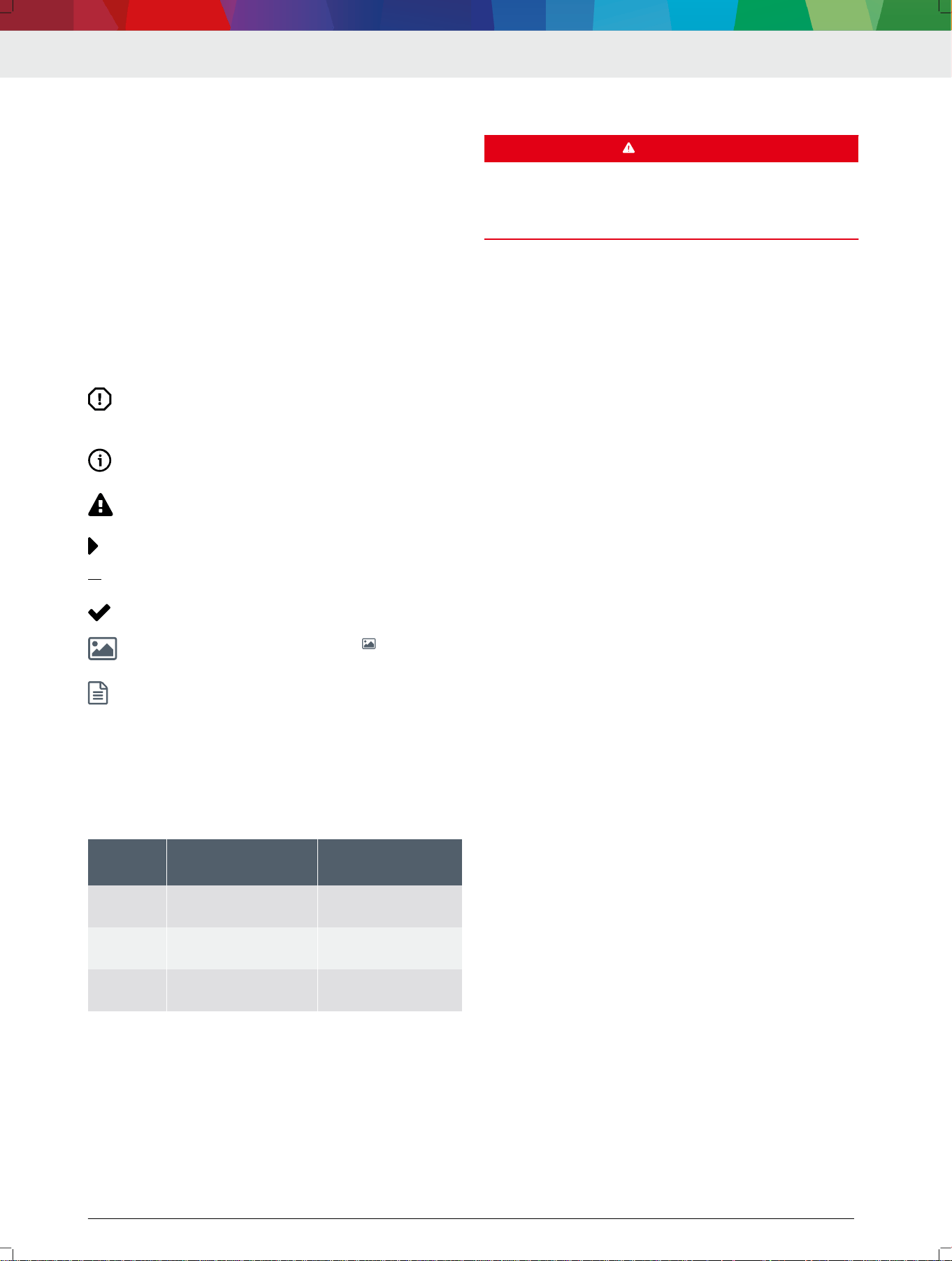
2.6 Foreseeable misuse
Misuse ( ) with corresponding intended use ( ):
The DAS 3000 S20 is pulled or pushed by the edge
protection frame to change the position.
Only use the handles to pull or push the
DAS 3000 S20 in order to change the position.
The edge protection frame can be damaged if the
DAS 3000 S20 is pulled or pushed by the edge
protection frame.
---Separator---
The DAS 3000 S20 is used as a means of transport
for heavy objects.
The DAS 3000 S20 may only be used for alignment of
calibration boards for front camera systems and
front radar systems.
---Separator---
2.7
Warranty and liability
No modications may be carried out on our products.
Our products may only be used with genuine accesso‐
ries and genuine spare parts. Otherwise, all warranty
claims will be rendered null and void.
---Separator---
3.
Product description
---Separator---
3.1
Prerequisites
Measurement bay
• Maximum inclination (x) in measurement bay: 1%
• Maximum unevenness of the resting surface of the
vehicle and DAS 3000: 10 mm
• Measurement bay must comply with the particular
values for the make
• No direct sunlight at the measurement bay
•
Adequate lighting
---Separator---
Bosch ADAS Positioning software
We recommend and support the DCU 220 as a
laptop or the KTS 350 tablet for use with Bosch
ADAS Positioning.
•
Operating system: Windows 10
•
Minimum resolution: 1024 x 600 pixels
•
WLAN
•
DAS 3000 S10: At least one free USB port
•
DAS 3000 S20: At least two free USB ports
---Separator---
Diagnostic softwareESI[tronic] 2.0 software with the
control unit diagnosis ESI[tronic] info type for calibrat‐
ing front camera systems and front radar sensors
---Separator---
3.2
Scope of delivery
Denomination Order number
Trolley with frame (including positioning unit) –
Holder for laptop/tablet 1 681 321 374
en | 20 | DAS 3000 S20
1 689 989 485 | 2020-08-01Robert Bosch GmbH
Denomination Order number
Indicator bar 1 682 329 109
Camera beam 1 683 050 053
Mounting adapter 1 (2x) 1 685 720 380
Calibration board retainer R 1 685 720 384
USB stick with Bosch ADAS Positioning soft‐
ware
1 687 370 328
Calibration board (CTA 300-1) 1 681 098 011
Contact plate (CTA 104-1) with edge protec‐
tion and retaining hooks
1 681 320 090
Wheel holder (CTA 100-1) (2x) 1 688 120 190
Reference board (CTA 400-1) (2x) 1 681 098 013
Reference board fastening parts set
(CTA 400-1) (2x)
1 687 010 635
---
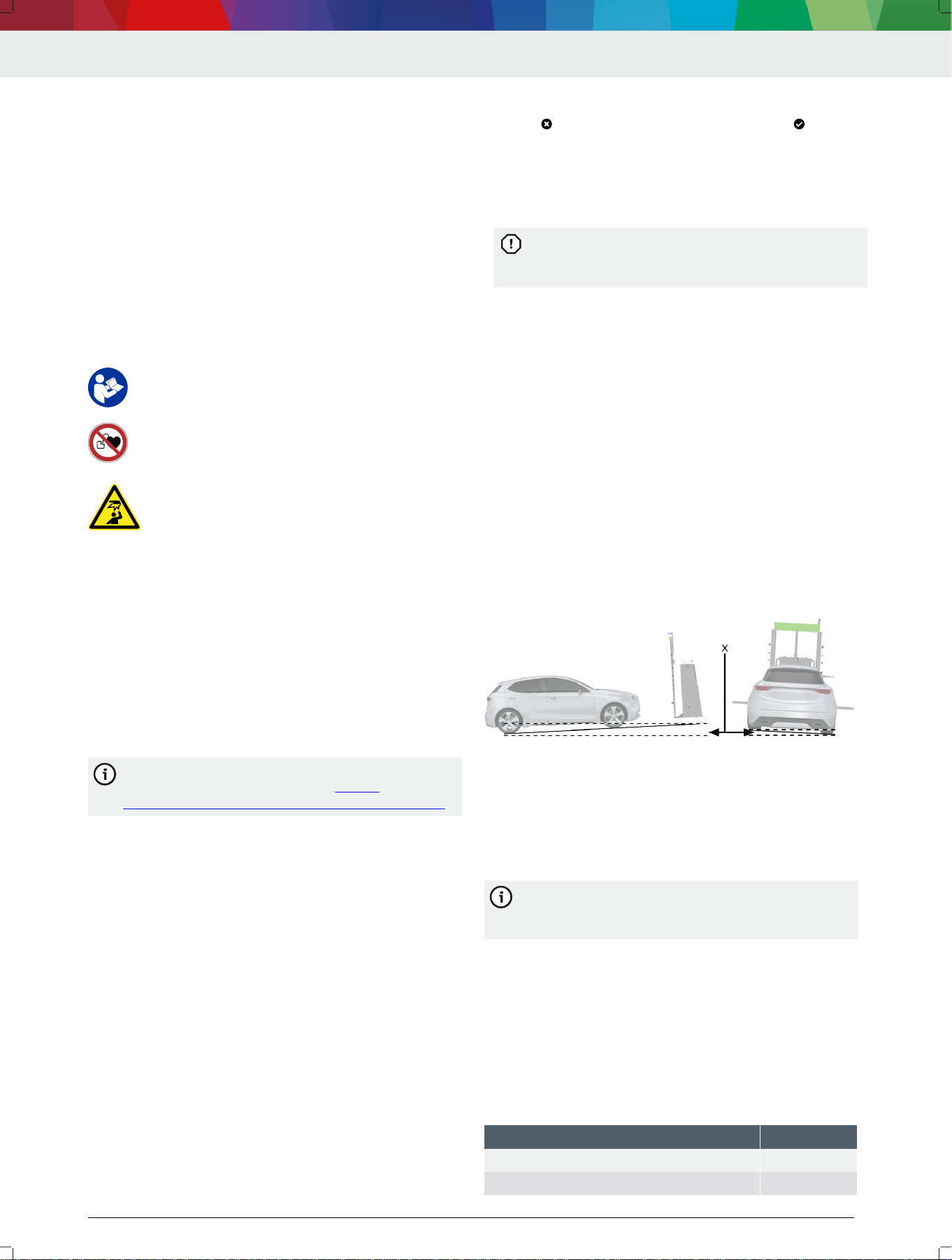
3.3
DAS 3000 S20 overview
4712009-01_shd
5
7
8
89
12
4
33
1
6
2
11
99
10
13
(1) Trolley
(2) 2-degree adjustment mechanism
(3) Positioning unit consisting of two positioning bars
(4) Calibration board retainer Y
(5) Calibration board retainer Z
(6) R position
(7) Indicator bar with slide
(8) Camera beam
(9) Cameras (2x) in camera beam
(10) Parked position for wheel holder (CTA 100-1)
(11) Brake for trolley
(12) Holder for laptop/tablet
(13) Handles for controlling the trolley
---
3.4 Accessory overview
4712009-02_shd
3
1
2
1
2
4
5
66
(1) Wheel holder (CTA 100-1)
(2) Reference board (CTA 400-1)
(3) Contact plate (CTA 104-1)
(4) Calibration board 1 681 098 011 (CTA 300-1)
(5) Safety adapter R
(6) Mounting adapter 1
---
3.5 Functional description
The following steps must be carried out to calibrate a
windshield camera or front radar sensor using the
DAS 3000 S20:
• Attach the calibration board specic to the manufac‐
turer to the DAS 3000 S20.
• Position the DAS 3000 S20 in front of the vehicle.
•
Use ESI[tronic] 2.0 to calibrate the windshield cam‐
era or front radar sensor.
---
In the following, the basic steps for positioning
the DAS 3000 S20 in front of the vehicle will be
set out. The Bosch ADAS Positioning software
will guide the user through the alignment process
for the DAS 3000 S20 step by step.
---
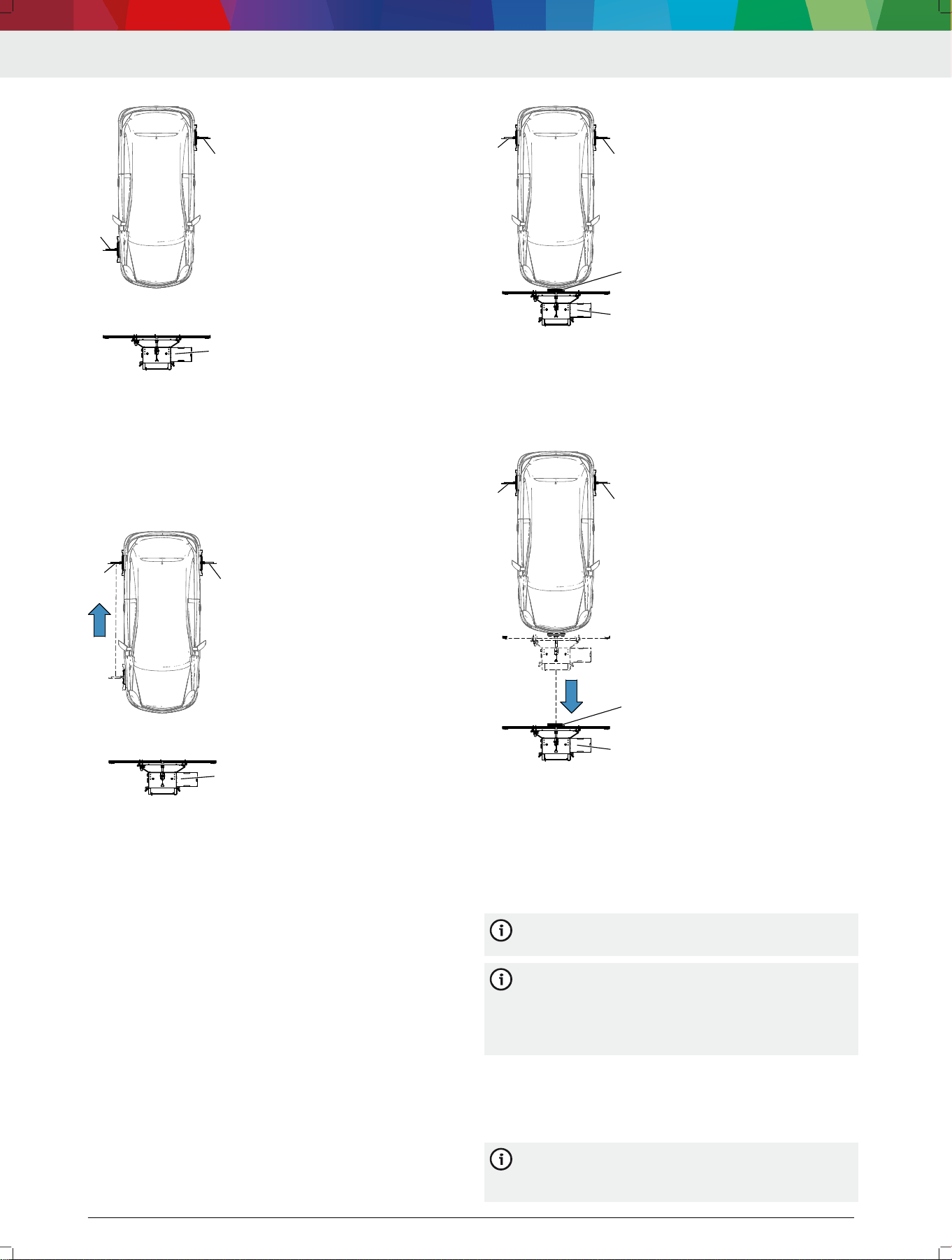
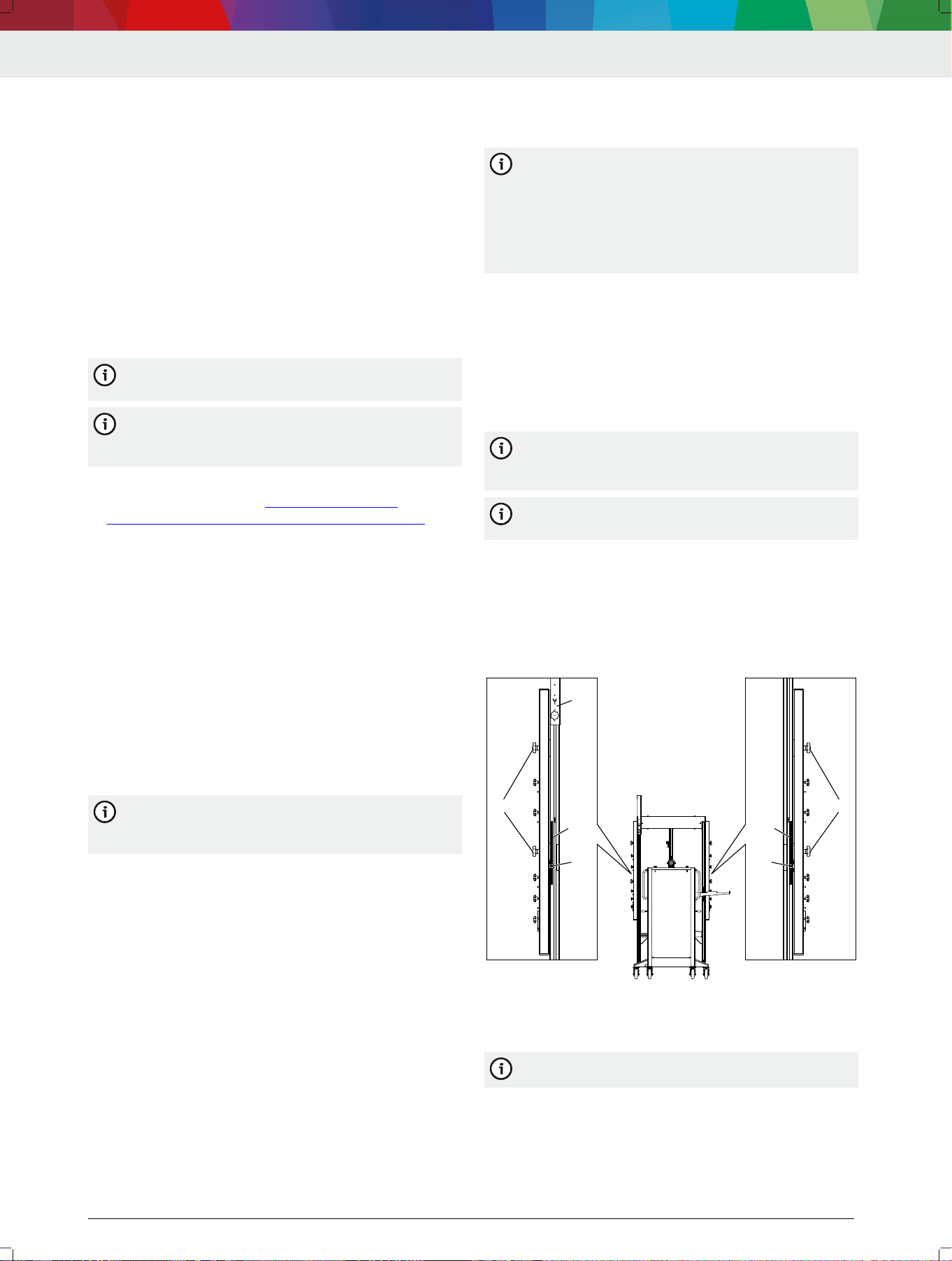
Positioning in front of the vehicle using the wheel hub
as a reference point
Step 1 – Position the DAS 3000 S20 at the required dis‐
tance: to do this, attach the wheel holders (CTA 100-x)
to the right front wheel and left rear wheel. Use
Bosch ADAS Positioning to place the DAS 3000 S20 at
the vehicle-specic distance from the wheel hub.
DAS 3000 S20 | 21 | en
1 689 989 485 | 2020-08-01 Robert Bosch GmbH
1
2
3
4712009-07_shd
(1) Wheel holder (CTA 100-x) on right front wheel
(2) Wheel holder (CTA 100-x) on left rear wheel
(3) DAS 3000 S20
Step 2 – Place the DAS 3000 S20 in the required posi‐
tion: to do this, attach the wheel holder attached to the
right front wheel to the right rear wheel. Use
Bosch ADAS Positioning to place the DAS 3000 S20 in
the required position.
3
4712009-08_shd
2
1
(1) Wheel holder (CTA 100-x) on right rear wheel
(2) Wheel holder (CTA 100-x) on left rear wheel
(3) DAS 3000 S20
---
Positioning in front of the vehicle using the bumper
as a reference point
Step 1 – Position the DAS 3000 S20 at the required dis‐
tance: to do this, attach the wheel holders (CTA 100-x)
to the left and right rear wheels. Attach the contact
plate (CTA 104-x) to the DAS 3000 S20. The
DAS 3000 S20 must be moved all the way to the bump‐
er so the contact plate (CTA 104-x) touches the bump‐
er.
4712009-09_shd
2
1
3
4
(1) Wheel holder (CTA 100-x) on right rear wheel
(2) Wheel holder (CTA 100-x) on left rear wheel
(3) Contact plate (CTA 104-x) on DAS 3000 S20
(4) DAS 3000 S20
Step 2 – Use Bosch ADAS Positioning to place the
DAS 3000 S20 in the required position.
4712009-10_shd
2
1
3
4
(1) Wheel holder (CTA 100-x) on right rear wheel
(2) Wheel holder (CTA 100-x) on left rear wheel
(3) Contact plate (CTA 104-x) on DAS 3000 S20
(4) DAS 3000 S20
---
4. Initial commissioning
---Separator---
4.1 Remove the DAS 3000 S20 from the
pallet
We recommend that two people remove the
DAS 3000 S20 from the pallet.
We recommend attaching the required compo‐
nents at the installation site of the
DAS 3000 S20. Maneuvering the pallet to the in‐
stallation site of the DAS 3000 S20 is safer and
easier without the components attached.
1.
Remove all loose components from the pallet.
2.
Remove all loose components in the trolley from the
DAS 3000 S20.
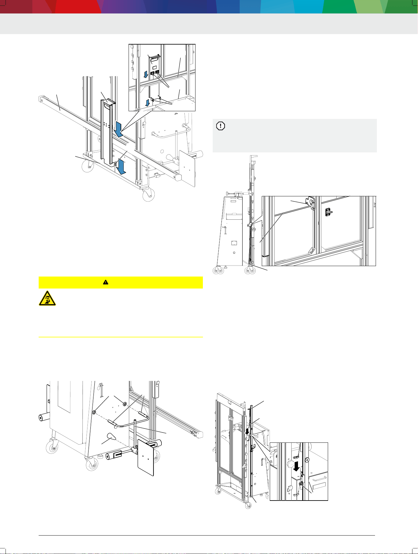
3.
Unscrew the camera beam from the frame.
The DAS 3000 S20 is secured on the back by a
mounting bracket (3). The DAS 3000 S20 is se‐
cured on the front by a screw (5).
en | 22 | DAS 3000 S20
1 689 989 485 | 2020-08-01Robert Bosch GmbH
4. Remove the mounting bracket (3) from the back of
the DAS 3000 S20.
5. Remove the screw (5) from the front of the
DAS 3000 S20.
Using the two wedges (1) supplied, pull the
DAS 3000 S20 off the pallet.
6. Place the wedges (1) supplied on the pallet in such
a way that the DAS 3000 S20 can be moved off the
pallet backwards.
7. Place the rollers (6) of the DAS 3000 S20 in the di‐
rection of travel.
If the rollers are not placed in the direction of
travel, the DAS 3000 S20 may be damaged when
being moved off the pallet.
8.
Hold the DAS 3000 S20 by the handles (4), and
carefully roll it off the pallet backwards using the
roll-off aid.
The DAS 3000 S20 must not be pulled or pushed
by its frame. Pushing or pulling the frame may
damage it.
1
2
3
4
4712005-33_shd
5
66
(1) Wedges
(2) Roll-off aid
(3) Mounting bracket with two screws on back
(4) Handles
(5) Screw on front
(6) Rollers placed in direction of travel
---Separator---
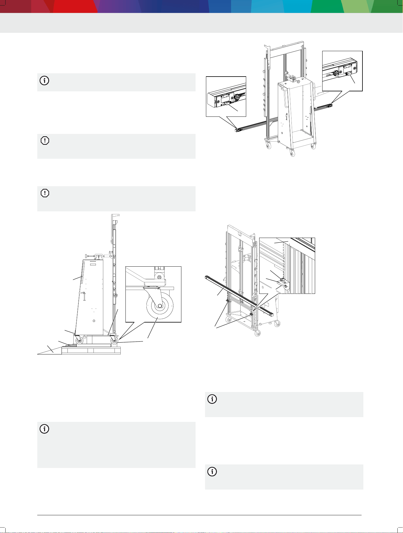
4.2
Mount the camera beam
(DAS 3000 S20 S20 only)
The camera beam must be positioned in the cor‐
rect orientation and fastened to the
DAS 3000 S20. The camera beam is positioned in
the correct orientation when the mini-USB ports
of the cameras in the camera beam point down‐
wards.
1.
Position the camera beam (2) so that the mini-USB
ports (1) of the cameras in the camera beam point
downwards.
4712005-59_shd
1
1
(1) Mini-USB ports
2.
Position the camera beam (2) with the holes in the
T-slot above the mountings (1).
3.
Place the camera beam on the mountings in such a
way that the T-slot nuts (3) are held in the T-slot of
the camera beam.
4.
Fasten the camera beam with screws from the un‐
derside of the mountings (4).
11
2
1
3
2
4517005-34_shd
4
(1) Mountings
(2) Camera beam
(3) T-slot nuts
(4) Screw on underside of mounting
---Separator---
4.3
Compensating for the DAS 3000 S20's
offset
It may be necessary to slightly shorten the cover
of the USB cable and to reposition the cable
clamp securing the USB cables.
---
1.
Use the brake to secure the DAS 3000 S20.
2.
Attach mounting adapter 1 (1) in vertical position A.
3.
Determine the vertical distance (2) between the
resting surface (3) and the front recess (4) of the
mounting adapter.
We recommend placing the meter stick against
the mounting adapter and camera beam for de‐
termining vertical distance.
DAS 3000 S20 | 23 | en
1 689 989 485 | 2020-08-01 Robert Bosch GmbH
The vertical distance between the resting surface
and the front recess of the mounting adapter
must be 820 mm.
4. If the vertical distance determined is not 820 mm:
use the knurled screws (5) to adjust the positioning
unit in such a way that the vertical distance (2) be‐
tween the resting surface (3) and the front recess
(4) of the mounting adapter is 820 mm.
11
22
33
4
4
4712009-19_shd
5555
(1) Mounting adapter 1
(2) Vertical distance between resting surface and front recess of
mounting adapter
(3) Resting surface
(4) Front recess of mounting adapter
(5) Knurled screws for vertical adjustment of positioning unit
5.
Loosen the screws (2) on the offset ruler (1).
1
22
4712009-16_shd
(1) Offset ruler
(2) Offset ruler screws
6.
Place the 0 point of the offset ruler precisely in the
height indicator (2) of the positioning unit.
1
1
4712009-18_shd
0
0
1
2
1
2
(1)
Offset ruler
(2) 0 point of offset ruler precisely in height indicator of positioning
unit
7.
Use the screws to secure the offset ruler.
---
4.4
Attaching the edge protection for the
contact plate (CTA 104-x)
Attach the edge protection to the trolley.
4712009-11_shd
---
4.5
Installing the holder for the laptop/
tablet
1.
Push the setscrews for the laptop/tablet shelf
through the upper or lower 4 holes.
— Use the upper or lower 4 holes depending on the
height needed.
2. Attach the laptop/tablet shelf (3) with washers (2)
and hex nuts (1).
en | 24 | DAS 3000 S20

1 689 989 485 | 2020-08-01Robert Bosch GmbH
1
2
3
1
2
3
4712005-36_shd
(1) Hex nut
(2) Washer
(3) Holder for laptop/tablet
---Separator---
4.6
Screwing in the retaining hooks for
the contact plate (CTA 104-x)
Screw the retaining hooks into the holes in such a way
that they point up.
4712009-12_shd
11
(1) Retaining hooks
---
4.7 Installing the KTS mount
The mount for the KTS 560/590 can be installed
on the DAS 3000 S20. The mount is part of the
scope of delivery of the KTS 560/590.
---
1. If the "Multi-Target-Shop" box is already installed, re‐
move it from the trolley.
2.
Use pan head screw ISO 7045-M4 x 6 and hex nut
ISO 4032-M4 to attach the mount for the
KTS 560/590 to the trolley.
Do not use longer screws for fastening. Longer
screws will damage the Multi-Target-Shop box
while it is attached to the trolley.
1
222
4712009-03_shd
(1) KTS 560/590 mount
(2) Pan head screws ISO 7045-M4 x 6
---
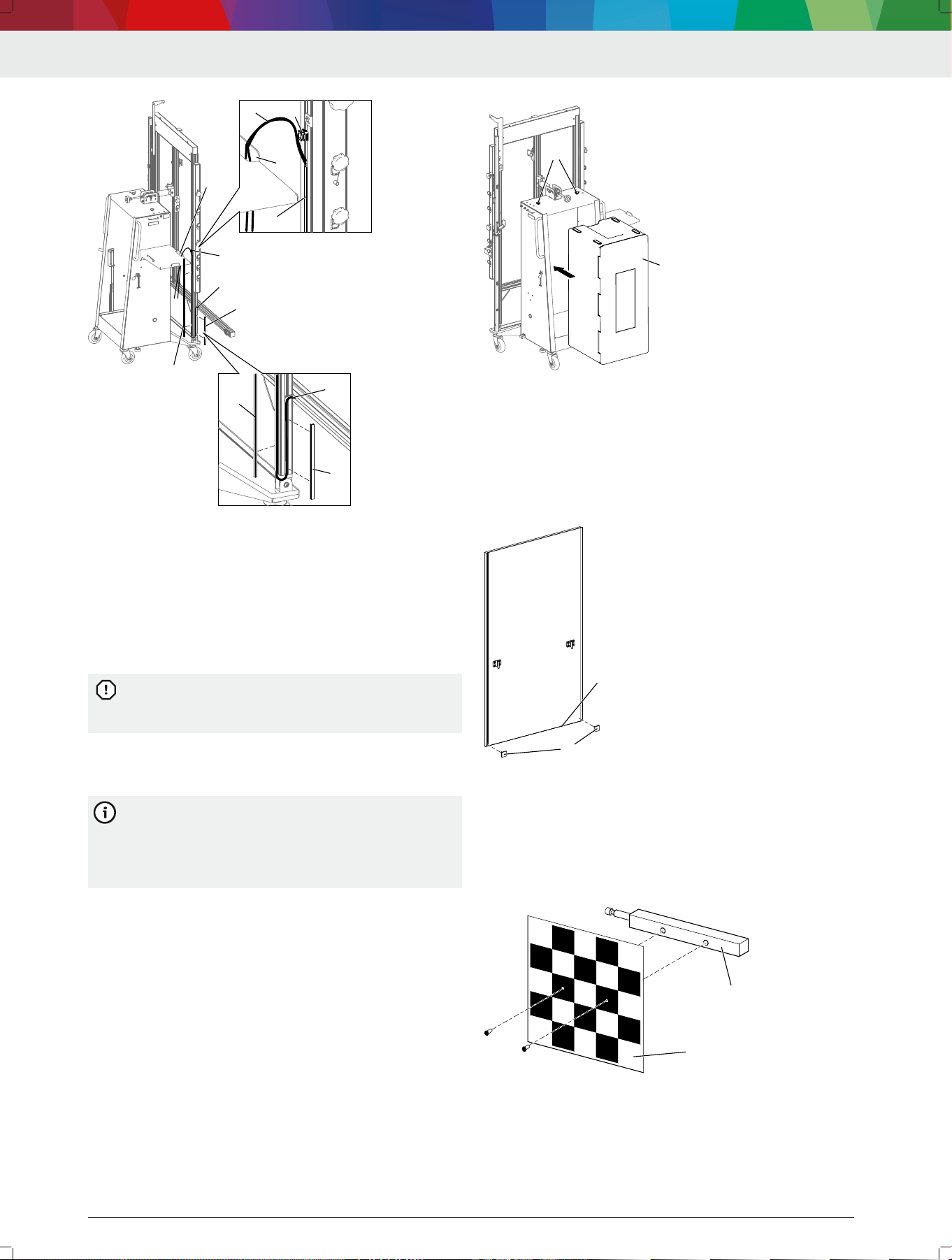
4.8
Install the USB connecting cables in
the camera beam (DAS 3000 S20 S20
only)
1.
Remove the long cover (1) and short cover (2) from
the proled slot.
2. Place the USB connecting cables (3) for the CCD
cameras in the camera beam in the outer slot of the
right, vertical prole (rear view).
3. Fasten the short cover (2) in the slot in such a way
that the installed USB connecting cables are cov‐
ered.
4.
Place the USB connecting cables in the rear slot of
the right, vertical prole up to the cable clamp (4).
5. Fasten the long cover (1) in the slot in such a way
that the installed USB connecting cables are cov‐
ered.
6. Attach the USB connecting cables (3) to the cable
clamp (4) by means of cable ties.
—
Make sure that the USB connecting cables have
enough slack to allow connection to the laptop/
tablet.
DAS 3000 S20 | 25 | en
1 689 989 485 | 2020-08-01 Robert Bosch GmbH
2
3
1
4
4712005-49_shd
5
1
2
3
3
4
1
5
(1) Long cover in the rear slot
(2) Short cover in the right slot
(3) USB connecting cables for CCD cameras in the camera beam
(4) Cable clamp
(5) Opening in the laptop/table shelf
7. Guide the USB connecting cables through the open‐
ing (5) in the laptop/tablet shelf in such a way that
USB connecting cables do not hang down along the
right prole to the rollers.
If the USB connecting cables are not run through
the opening (5), they may be damaged because
of their length when the DAS 3000 S20 is moved.
---Separator---
4.9 Attaching the "Multi-Target Shop" box
to the DAS 3000 S20
The "Multi-Target Shop" box for safe storage of
calibration boards with magnetic attachment is
not included in the scope of delivery for the
DAS 3000 S20. The box can be placed in and fas‐
tened to the trolley of the DAS 3000 S20.
1.
Place the "Multi-Target Shop" box (1) in the trolley.
2.
Secure the box with two knurled screws (2).
4712005-40_shd
1
22
(1) "Multi-Target Shop" box
(2) Knurled screws
---Separator---
4.10
Attaching the corner guards to the
calibration board (CTA 300-x)
Attach the corner guards (1) to the bottom edge (2)
of calibration board CTA 300-x.
4712005-62_shd
1
1
2
(1) Corner guards
(2) Bottom edge of calibration board CTA 300-x
---Separator---
4.11 Installing the reference board (CTA
400-x)
Use two screws to fasten reference board CTA 400-x
(1) to the socket pin (2).
4712005-35_shd
1
2
(1) Reference board (CTA 400-x)
(2) Socket pin
---
en | 26 | DAS 3000 S20
1 689 989 485 | 2020-08-01Robert Bosch GmbH
4.12 Installing the Bosch ADAS Positioning
software
1. Connect the USB stick to the laptop/tablet.
— Should the USB stick not be started automatically,
open the USB stick directory.
2. Open "Bosch ADAS Positioning Setup.exe."
3. Select the language for the installation wizard.
The installation wizard will start.
4.
Follow the installation steps.
Once the installation is complete,
Bosch ADAS Positioning can be used.
---Separator---
4.13
Installing ADAS Positioning using
DDM
Bosch ADAS Positioning is available through Diag‐
nostics Download Manager (DDM).
The customer number and password are included
on the delivery slip of the Bosch diagnostic pro‐
gram.
1.
Should DDM not be installed yet, download DDM
from the following link: https://www.down‐
loads.bosch-automotive.com/de/ddm/esi20-eu/ .
2.
Use the customer number and password to log into
DDM.
3. Perform the one-time conguration of DDM.
4. Select Bosch ADAS Positioning for installation.
Bosch ADAS Positioning will be installed on the
laptop/tablet.
Updates of Bosch ADAS Positioning will be auto‐
matically installed by DDM.
---Separator---
4.14 Initializing cameras using the QR
code
Bosch ADAS Positioning must be installed on the
laptop/tablet.
The camera QR code must be available.
---
Bosch ADAS Positioning guides the user through
the camera initialization process by QR code step
by step.
1. Start Bosch ADAS Positioning.
2.
Remove the protective cap from the camera lens if it
is still attached.
3.
Use the USB cable to connect the camera to the lap‐
top/tablet.
The camera will be initialized.
The camera image will be displayed.
4.
Check the serial number on the QR code document
to make sure the QR code matches the camera to be
initialized.
5.
Place the included QR code inside the green box in
the camera image.
The camera will be adapted.
6.
Specify the camera position in
Bosch ADAS Positioning.
The camera is now ready for operation.
The serial number of the camera will be saved to
the settings.
---
5. Operation
---Separator---
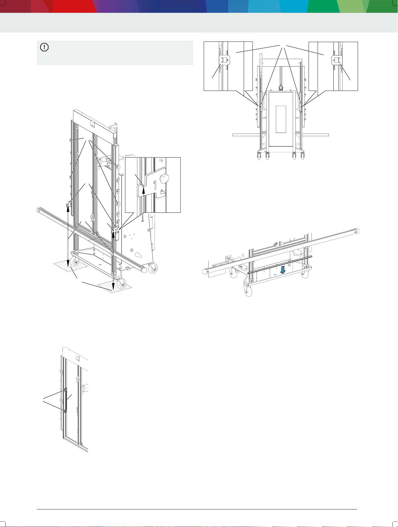
5.1 Compensating for vertical offset
Vertical offset refers to a difference between the
height at which the DAS 3000 S20 is set up and
the vehicle. The difference can result from lifts or
leveling surfaces on which the vehicle is posi‐
tioned during the calibration. The DAS 3000 S20
can compensate for a vertical offset of up to
30 cm.
---
A vertical offset exists due to a lift or leveling sur‐
face.
The vertical offset does not exceed 30 cm.
---
1.
Measure the vertical offset.
2.
Loosen the knurled screw on calibration board re‐
tainer Y (4), and push calibration board retainer Y to
the highest position.
The positioning bar will be blocked by calibration
board retainer Y if calibration board retainer Y is
not pushed up.
Set the measured vertical offset on both posi‐
tioning bars one after the other.
3.
Loosen the knurled screws (1) on the positioning
bar slightly.
4. Slide the positioning bar up by the measured value,
and use the height indicator (2) to position it pre‐
cisely.
5. Tighten the knurled screws (1) on the positioning
bar.
11
2
3
4
11
2
3
4712005-30_shd
(1) Knurled screws
(2) Height indicator
(3) Scale on back of frame
(4) Calibration board retainer Y
The vertical offset can be adjusted at any time.
DAS 3000 S20 | 27 | en
1 689 989 485 | 2020-08-01 Robert Bosch GmbH
6. Attach the indicator bar to the positioning bars at
1.50 m.
7. Use the spirit level in the indicator bar to check
whether the left and right positioning bars are
aligned properly.
— If the spirit level shows an inclination, adjust the
left and right positioning bars precisely.
---
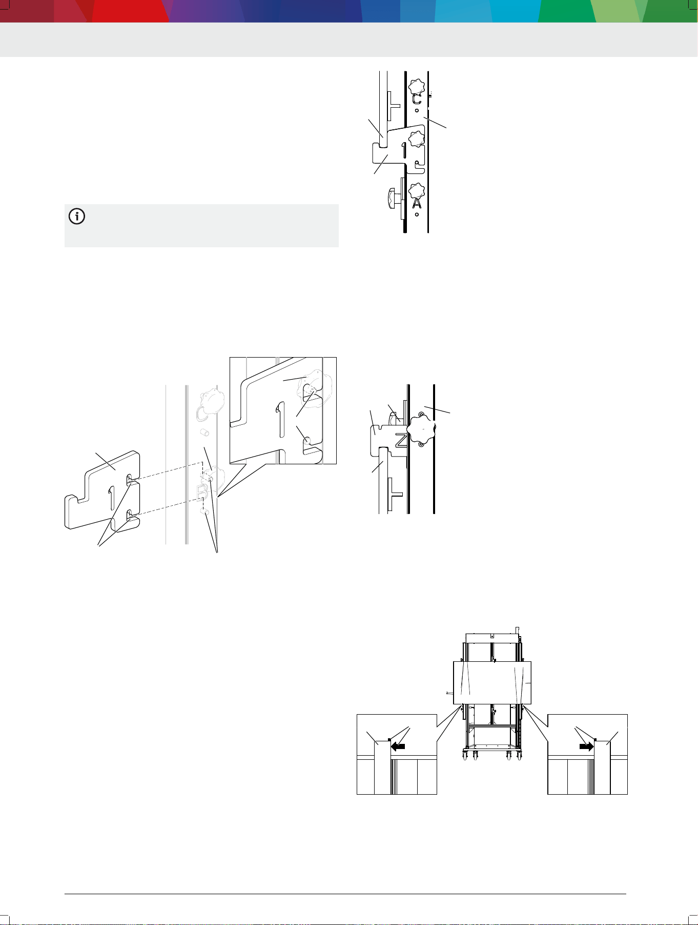
5.2 Attaching the calibration board in
vertical positions A, B or C
The mounting adapters are used for attaching all
calibration boards CTA 3xx-x to the
DAS 3000 S20.
---
1.
Mount the mounting adapter (1) at vertical position
A, B or C.
2.
Make sure the mounting adapter correctly engages
with the mounting pins (3) by the mounting guides
(2).
3.
Use the knurled screw (4) to hand-tighten the
mounting adapter.
1
22
33
4
33
4
4712005-23_shd
(1) Mounting adapter
(2) Mounting guides
(3) Mounting pin
(4) Knurled screw
CAUTION – Pinch point hazard when positioning the
calibration board.
4. Do not place ngers or hands between the mounting
adapter (1) and the bottom edge (2) of the calibra‐
tion board.
5.
Place the bottom edge of the calibration board (2) in
the mounting adapter (1) on the positioning unit (3).
1
2
3
4712005-24_shd
(1) Mounting adapter
(2) Bottom edge of calibration board
(3) Positioning unit
6.
Push calibration board retainer Z (1) onto the top
edge (3) of the calibration board in such a way that
the recess in calibration board retainer Z secures the
calibration board.
7.
Use the knurled screw (2) to hand-tighten calibra‐
tion board retainer Z.
The calibration board is now secured and xed in
place.
4712005-25_shd
1
2
3
4
(1) Calibration board retainer Z
(2) Top edge of calibration board
(3) Positioning unit
8.
Make sure that the arrow and marking (2) on the
bottom edge of the calibration board align with the
mounting adapters (1).
The calibration board is centered relative to the
DAS 3000 S20.
1
22
1
22
4712005-26_shd
(1) Mounting adapter
(2) Arrow and mark on calibration board for centering
---
en | 28 | DAS 3000 S20
1 689 989 485 | 2020-08-01Robert Bosch GmbH
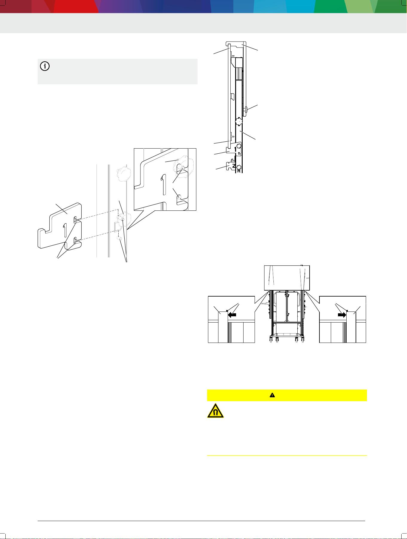
5.3 Attaching the calibration board in
vertical position D
The mounting adapters are used for attaching all
calibration boards CTA 3xx-x to the
DAS 3000 S20.
---
1. Mount the mounting adapter (1) at vertical position
D.
2.
Make sure the mounting adapter correctly engages
with the mounting pins (3) by the mounting guides
(2).
3.
Use the knurled screw (4) to hand-tighten the
mounting adapter.
1
22
33
4
33
4
4712009-04_shd
(1) Mounting adapter
(2) Mounting guides
(3) Mounting pin
(4) Knurled screw
4. Position calibration board retainer Z (1) on the cen‐
ter vertical bar below vertical position D.
CAUTION – Pinch point hazard when positioning the
calibration board.
5.
Do not place ngers or hands between the mounting
adapter (2) and the bottom edge (3) of the calibra‐
tion board.
6. Place the bottom edge of the calibration board (3) in
the mounting adapter (2) on the positioning unit (7).
7. Push calibration board retainer Y (5) onto the top
edge (4) of the calibration board in such a way that
the recess in calibration board retainer Y secures the
calibration board.
8.
Use the knurled screw (6) to hand-tighten calibra‐
tion board retainer Y.
The calibration board is now secured and xed in
place.
4712005-27_shd
1
2
3
4
5
6
7
(1) Calibration board retainer Z
(2) Mounting adapter
(3) Bottom edge of calibration board
(4) Top edge of calibration board
(5) Calibration board retainer Y
(6) Knurled screw on calibration board retainer Y
(7) Positioning unit
9. Make sure that the arrow and marking (2) on the
bottom edge of the calibration board align with the
mounting adapters (1).
The calibration board is centered relative to the
DAS 3000 S20.
1
22
1
22
4715002-28_shd
(1) Mounting adapter
(2) Arrow and mark on calibration board for centering
---
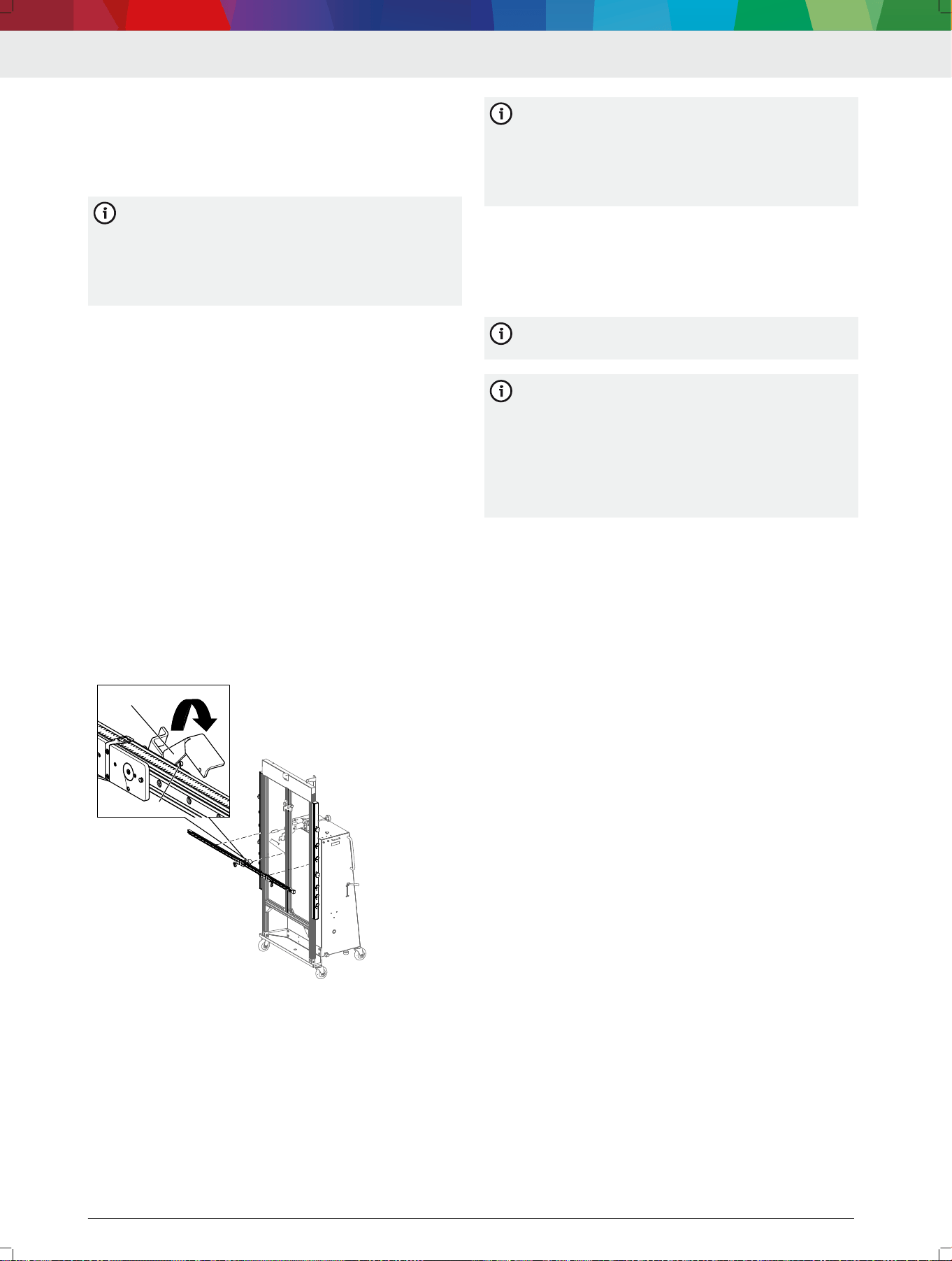
5.4
Attaching the indicator bar to the
frame
CAUTION
Magnetic elds from strong magnets on the in‐
dicator bar. Minor injury to people with a pace‐
maker or implanted debrillator.
People with a pacemaker or implanted debril‐
lator must maintain a sucient distance from
the DAS 3000 S20, especially from the indicator
bar.
---
No calibration board is attached at vertical positions
A, B, C or D.
Calibration board CTA 300-1 is in the parked posi‐
tion.
DAS 3000 S20 | 29 | en
1 689 989 485 | 2020-08-01 Robert Bosch GmbH
The mounting adapters are suspended from the han‐
dle and not attached at vertical positions A, B, C or
D.
The height at which the indicator bar is to be posi‐
tioned is known.
---
The required height can be read off the top edge
of the indicator bar. The offset (approx. 15 mm)
from the center of the indicator bar, where the
calibration boards CTA 2xx-x are attached, is al‐
ready taken into consideration in terms of height
adjustment.
1.
Press down and hold the locking lever on the indica‐
tor bar.
The safety mechanism will be open so that the in‐
dicator bar can be attached.
CAUTION – Pinch point hazard due to magnetic
force.
2.
Do not place ngers or hands between the indicator
bar and the positioning bars.
3.
Position the indicator bar at the required height:
—
Position the guide pin (2) exactly in front of the T-
slot in the center prole.
—
Place the magnets on the indicator bar in front of
the positioning bars on the left and right.
The indicator bar is pulled against the positioning
bars by magnetic force.
The guide pin on the indicator bar is located in
the T-slot of the center prole.
4. Release the locking lever.
The safety mechanism is engaged on the center
prole.
1
2
4712005-29_shd
(1) Locking lever
(2) Guide pin
5.
Use the scale on the positioning bars on the left and
right to precisely align the indicator bar at the exact
height.
6.
Use the spirit level on the indicator bar to check
whether the DAS 3000 S20 is standing on a level
surface.
—
If the spirit level indicates an inclination, use the
spirit level to level the indicator bar.
If one of the positioning bars is moved up or
down more than 1 cm while the indicator bar is
being leveled, the inclination of the measurement
bay does not allow for the calibration of ad‐
vanced driver assistance systems. The measure‐
ment bay is not suitable for calibration.
---
5.5
Attaching the calibration board to the
indicator bar
The indicator bar is positioned on the frame at the
required height.
---
The indicator bar is used for attaching all calibra‐
tion boards CTA 2xx-x to the DAS 3000 S20.
---
If only one Multi-Target-Shop calibration board is
needed for front camera calibration, the board
must be attached to the left slide. If the calibra‐
tion board is attached to the right slide, the pat‐
tern on the calibration board will be rotated by
180° and front camera calibration will fail. The
right slide is used only if two Multi-Target-Shop
calibration boards are needed.
1.
Pay attention to the mounting pin on the calibration
board and the mounting pin on the slide.
CAUTION – Pinch point hazard due to magnetic
force.
2.
Do not place ngers or hands between the indicator
bar and calibration board.
3. Position the calibration board in front of the magnet‐
ic mount on the left slide.
The calibration board will be pulled against the
left slide by magnetic force.
The mounting pin on the calibration board and
the mounting pin on the left slide will engage cor‐
rectly.
4.
Attach the retaining cable to a lock ring on the back
of the calibration board.
The calibration board is now secured against fall‐
ing.
---Separator---
5.6
Attaching the contact plate (CTA 104-
x) to the DAS 3000 S20
1.
Position the contact plate (CTA 104-x) on the cam‐
era beam with the mounting bracket.
2.
Make sure the recesses of the contact plate engage
with the edge of the trolley.
en | 30 | DAS 3000 S20
1 689 989 485 | 2020-08-01Robert Bosch GmbH
4512009-13_shd
1
2
3
44
55
5
2
1
3
(1) Camera beam
(2) Edge of trolley
(3) Contact plate (CTA 104-x)
(4) Mounting bracket
(5) Recesses
---
5.7
Attaching the wheel holder (CTA 100-
x) with the reference board (CTA 400-
x) in the parked position
CAUTION
Risk of striking one's head on the mount for
the laptop/tablet. Minor injury.
One parked position is located below the
mount for the laptop/tablet. Pay attention to
the mounting for the laptop/tablet when remov‐
ing or attaching wheel holder CTA 100-x.
---
Engage wheel holder CTA 100-x (1) by placing the
prongs (2) into the holes intended for this purpose
(3).
Wheel holder CTA 100-x is now resting against the
rubber buffer (4).
1
2
33
4
4712009-05_shd
2
(1) Wheel holder CTA 100-x
(2) Prongs
(3) Holes
(4) Rubber buffer
---
5.8 Attaching calibration board 1 681 098
011 (CTA 300-1) in the parked posi‐
tion
1. Set down calibration board CTA 300-1 (3) between
the frame and trolley on the edge protection (1).
2. Make sure calibration board CTA 300-1 does not trap
the USB cable at the bottom of the frame.
3. Use safety adapter R (2) to secure calibration board
CTA 300-1 (3) at the top edge.
If calibration board CTA 300-1 is not secured in
the parked position by safety adapter R (2), it
may be damaged when the DAS 3000 S20 is posi‐
tioned or moved.
2
1
4712005-38_shd
33
(1) Edge protection
(2) Safety adapter R
(3) Calibration board CTA 300-1
---Separator---
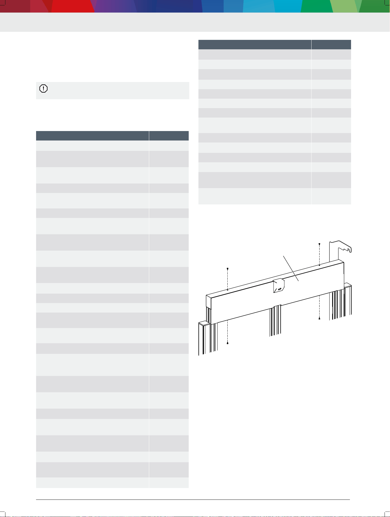
5.9 Fastening the indicator bar in the
parked position
1. Push both slides (4) on the indicator bar up.
2. Position the indicator bar (1) in the mount (2) near
the bottom of the trolley.
3.
Clamp one slide (4) in the retaining bolts (3) near
the top of the trolley.
The indicator bar is now in the parked position.
The clamped slide (4) secures the indicator bar in
the retaining bolts (3).
1
2
4
4
33
4712005-37_shd
(1) Indicator bar
(2) Mount
DAS 3000 S20 | 31 | en
1 689 989 485 | 2020-08-01 Robert Bosch GmbH
(3) Retaining bolts
(4) Slide
---Separator---
5.10 Storing the mounting adapter on the
handle
Place the mounting adapter (1) on the handle (2).
1
2
4712005-39_shd
(1) Mounting adapter
(2) Handle
---Separator---
5.11
Using the 2-degree adjustment
The 2-degree adjustment is only needed for front
radar calibration.
CAUTION – Pinch point hazard from guided 2-degree
adjustment.
1. Do not place ngers and hands between the handle
and guide of the 2-degree adjustment.
2. Operate the 2-degree adjustment only by the handle
(1).
3. Lift the handle (1) slightly and pull towards the back
to set the edge protection frame (2) at position 3.
4.
Lift the handle (1) slightly and push towards the
front to set the edge protection frame (2) at position
1.
1
4712005-31_shd
2
(1) Handle on the 2-degree adjustment
(2) Edge protection frame
---Separator---
5.12
Securing the DAS 3000 S20 with the
brake
CAUTION – Pinch point hazard from guided brake
mechanism.
1.
Do not place ngers and hands between the brake
lever (1) and brake guide (2).
2.
Operate the brake lever only by means of the handle.
3.
Pull the handle up slightly and lower the brake along
the guide.
The rubber buffer (3) on the brake contacts the
oor and stops the DAS 3000 S20.
3
1
2
4712005-32_shd
(1) Brake lever
(2) Brake guide
(3) Rubber buffer on brake
---Separator---
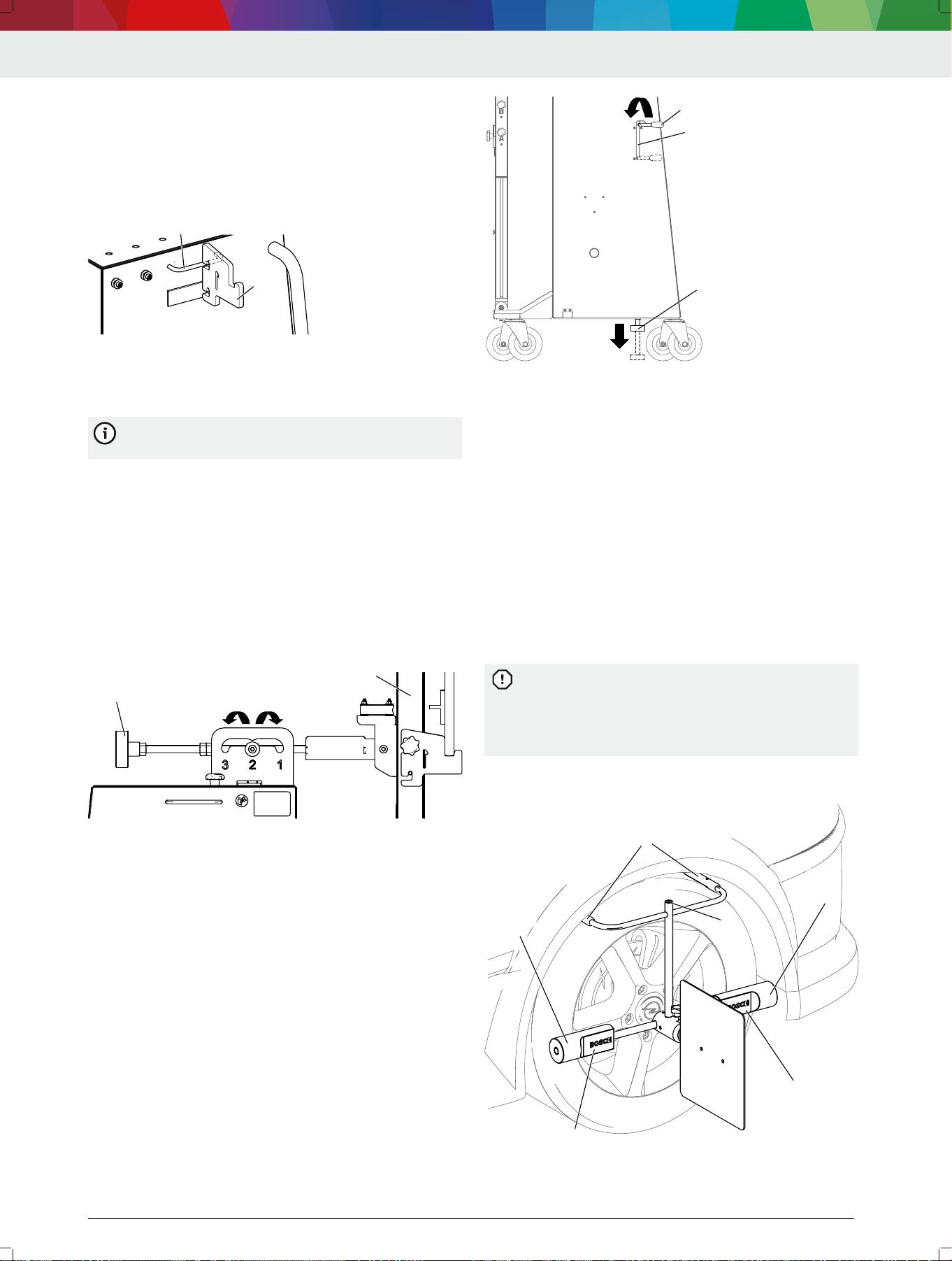
5.13
Attaching the wheel holder (CTA 100-
x) with the reference board (CTA 400-
x) to a wheel
Reference board CTA 400-x is attached to wheel
holder CTA 100-x.
---
1.
With its prongs (1), set down wheel holder
CTA 100-x on the tread of the tire.
2. Make sure the spacers (2) touch the sidewall of the
tire.
— In case of a protruding rim: turn the spacer until
the recess (3) in the spacer faces the rim.
The spacer must touch the sidewall of the tire. If
the spacer touches the rim, reference board
CTA 400-x will not be positioned accurately. It will
not be possible to align the DAS 3000 S20 accu‐
rately.
3. Use the spirit level (4) to level wheel holder
CTA 100-x.
1
1
2
2
3
3
4712009-06_shd
4
(1) Prongs
(2) Spacers
en | 32 | DAS 3000 S20
1 689 989 485 | 2020-08-01Robert Bosch GmbH
(3) Recess in spacer
(4) Spirit level
---
6. Maintenance
---Separator---
6.1 Cleaning
Coarse workshop rags and abrasive cleaning
agents may damage the DAS 3000 S20 .
Use only neutral cleaning agents and soft cloths to
clean the DAS 3000 S20.
---Separator---
6.2
Spare parts
Denomination Order number
Rubber buffer (2x) on brake
<)
1 688 990 086
Star knob screws (2x) for attaching the "Multi-
Target-Shop" box
<)
1 686 621 080
Hammer nuts (2x) for the top camera's
mount
<)
3 842 530 283
Camera beam (without cameras) 1 682 391 559
Yellow protective caps (2x) for the camera
beam
1 683 212 042
Indicator bar with slide 1 682 329 109
Left slide (as viewed from the front) on the
indicator bar
<)
1 688 030 217
Right slide (as viewed from the front) on the
indicator bar
<)
1 688 030 215
Yellow protective caps (2x) for the indicator
bar
<)
1 683 212 041
End caps (2x) for the slide guide on the indi‐
cator bar
<)
1 683 212 040
Retaining cable
<)
1 684 712 028
Rubber magnets on the indicator bar 1 688 120 188
Spirit level on the indicator bar 1 687 233 114
Left positioning bar (as viewed from the
front)
1 688 040 326
Right positioning bar (as viewed from the
front)
1 688 040 323
Slider (2x) for the positioning bar
<)
3 842 552 424
Star handles (5x) suitable for vertical posi‐
tions A, B, C, D, radar position R, R position,
Z position
<)
1 686 621 078
Star handles (2x) suitable for securing the po‐
sitioning bar
<)
1 686 621 077
Star handle (1x) suitable for securing at the R
position and Z position
<)
1 686 621 081
T slot nut (2x) for the slider
<)
3 842 528 735
Left tape measure for the height of the indica‐
tor bar (as viewed from the front)
<)
1 687 233 119
Right tape measure for the height of the indi‐
cator bar (as viewed from the front)
<)
1 687 233 117
Cable carrier
<)
3 842 555 180
Calibration board CTA 300-1 for front camera
systems and front radar systems
1 681 098 011
Mounting adapter 1 (2x)
<)
1 685 720 380
Denomination Order number
Mounting adapter R (1x)
<)
1 685 720 384
Wheel holder CTA 100-1 1 688 120 190
Reference board CTA 400-1
<)
1 681 098 013
Wheel holder CTA 100-1 star handle 1 686 621 083
Wheel holder CTA 100-1 spacers (2x) 1 687 016 229
Wheel holder CTA 100-1 prongs (2x) 1 687 016 230
Wheel holder CTA 100-1 top bracket parts set 1 687 016 228
Reference board CTA 400-1 fastening parts
set
1 687 010 635
Contact plate CTA 104-1 1 681 320 090
Contact plate CTA 104-1 edge protection
<)
1 687 010 742
Left offset ruler (as viewed from the front) 1 688 132 049
Right offset ruler (as viewed from the front) 1 688 132 050
Rubber grommets (4x) for the parked position
of wheel holder CTA 400-x
<)
1 680 212 064
Rubber buffers (2x) for the parked position of
wheel holder CTA 400-x
<)
1 688 990 087
---
<)
Wearing parts
---
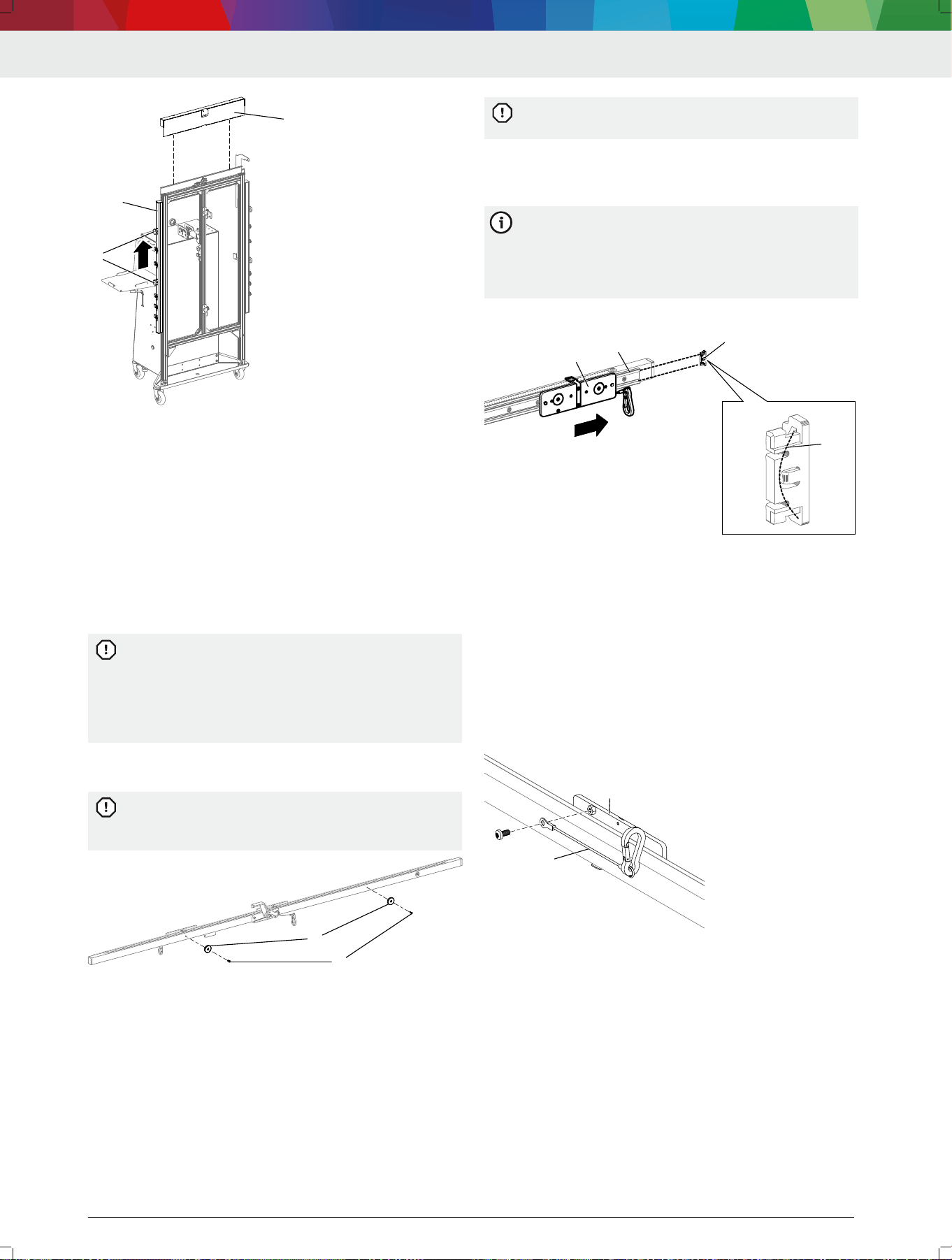
6.3 Replacing the positioning bar
1. Remove the front cover (1) on the frame.
4712005-44_shd
1
(1) Front cover
2.
Loosen the knurled screws (3) for adjusting the
height of the positioning unit (2).
3.
Push the positioning unit (2) up and out of the edge
protection frame.
DAS 3000 S20 | 33 | en
1 689 989 485 | 2020-08-01 Robert Bosch GmbH
1
2
33
4712005-45_shd
(1) Front cover
(2) Positioning unit
(3) Knurled screws for height adjustment
4.
Insert the new positioning unit into the edge protec‐
tion frame and secure it at the required height by
means of the knurled screws.
5. Attach the cover to the edge protection frame.
---Separator---
6.4 Replacing the magnets on the indica‐
tor bar
1.
Loosen the screws (1) on the indicator bar and re‐
place both magnets (2).
If only one of the magnets is replaced, the indica‐
tor bar will be held to the DAS 3000 S20 by mag‐
nets with different forces. To ensure a suciently
strong magnetic force and prevent damage from
parts dropping, it is always necessary to replace
both magnets.
2. Attach magnets with a maximum tightening torque of
0.5 Nm.
If the magnets are attached with a tightening tor‐
que greater than 0.5 Nm, the magnets and the in‐
dicator bar can be damaged.
1
1
22
4712005-54_shd
(1) Screws
(2) Magnets
---Separator---
6.5
Replacing slides and end caps of the
slide guide on the indicator bar
1.
Remove the end cap from the slide guide with the
aid of a pliers.
—
Make sure that the spring in the end cap does not
drop out when the end cap is being removed.
If the spring drops out and is lost, the end cap
can no longer be attached to the slide guide.
2. Remove the slide with stop from the slide guide.
3. Push the new slide with stop into the slide guide in
such a way that the mounting pin points inwards.
If the slides are pushed into the slide guide with
the mounting pin pointing outwards, the calibra‐
tion board will be rotated by 180° when fastened
to the indicator bar. The front camera calibration
will fail.
4.
Attach the end cap to the slide guide.
1
2
3
4
4712005-42_shd
(1) Slide with stop
(2) Slide guide
(3) End cap
(4) Spring in the end cap
---Separator---
6.6 Replacing the arrestor cable on the
slides
1. Remove the screw from the slide with stop (1).
2. Remove the arrestor cable (2) and attach new ar‐
restor cable.
3.
Secure the cable with the screw.
1
2
4712005-43_shd
(1) Slide with stop
(2) Arrestor cable
---Separator---
en | 34 | DAS 3000 S20

1 689 989 485 | 2020-08-01Robert Bosch GmbH
6.7 Replacing the rubber buffer on the
brake
Unscrew the rubber buffer (1) and replace it with a
new one.
1
4712005-41_shd
(1) Rubber buffer
---Separator---
7. Decommissioning
---Separator---
7.1
Changing location
If the DAS 3000 S20 is passed on, all the documenta‐
tion included in the scope of delivery must be handed
over together with the unit.
The DAS 3000 S20 is only ever to be transported in
the original or equivalent packaging.
Heed the notes on initial commissioning.
---Separator---
7.2 Disposal
Dismantle the DAS 3000 S20 and sort out and dis‐
pose of the different materials in accordance with the
applicable regulations.
---Separator---
8.
Technical data
---Separator---
8.1
DAS 3000 S20 specications
Property Specication
DAS 3000 S20 weight 127.75 kg
DAS 3000 S20 height x width x depth di‐
mensions
2080 mm x
2308 mm x 791 mm
---
DAS 3000 S20 | 35 | en

1 689 989 485 | 2020-08-01Robert Bosch GmbH
DAS 3000 S20 | 501 | zh
Robert Bosch GmbH
Franz-Oechsle-Str. 4
73207 Plochingen
Deutschland
www.bosch.com
1 689 989 485 | 2020-08-01
