
1
2
3
4
5
13
14
15
16
18
19
20
21
22
23
9
10
11
12
28 27
6
8
26
25
25
24
24
29
1
30
31
32
33
34
35
36
37
38
39
40
41
42
39 40
41
43
31
32
44
24 25
26
17
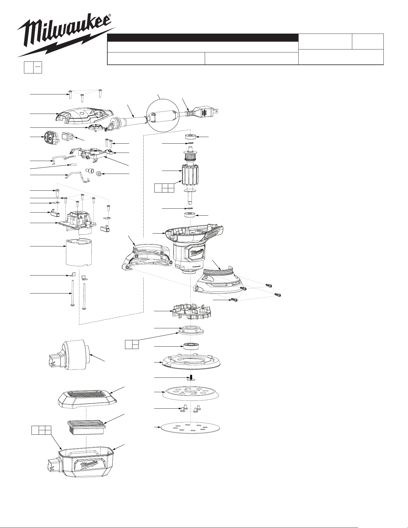
FIG. PART NO. DESCRIPTION OF PART NO. REQ.
1 06-81-0145 8-18 x 5/8" Pan Hd. T-15 Screw 7
2 31-12-0045 Top Cap 1
3 22-75-0090 Dial 1
4 42-38-0165 Cap 1
5 23-66-0245 Switch 1
6 44-76-0315 Strain Relief 1
8 22-64-1210 Cord 1
9 06-81-0150 6-19 x 5/8" Pan Hd. T-15 Screw 2
10 31-17-0530 Cord Clamp 1
11 14-20-0185 PCBA Assembly 1
12 22-56-5317 Wire Connector (see wiring) 2
13 23-94-2665 Receptacle w/ Wire 1
14 --------------- Tube 1
15 23-94-0555 Wire 1
16 05-74-0995 8-16 x 1/2" Pan Hd. T-20 Screw 2
17 06-81-0135 6-19 x 7/16" Pan Hd. T-15 Screw 4
18 22-38-0180 Clamp Brush 2
19 22-18-1170 Carbon Brush Assembly 2
20 31-12-0405 Bracket 1
21 18-10-0142 Motor Field 1
22 42-70-1005 Retaining Clip 2
23 06-81-0130 8-10 x 2-1/8" Pan Hd. T-20 Screw 2
24 --------------- Bearing 2
25 --------------- C-Ring 2
26 --------------- Armature 1
27 31-50-0295 Motor Housing 1
28 31-15-0630 Lower Housing Support 1
29 31-15-0635 Lower Housing Cover 1
30 22-84-0980 Fan 1
31 --------------- Bearing Cap 1
32 --------------- Bearing 1
33 44-52-0970 Brake 1
34 06-81-0165 8-32 x 3/8" Pan Washer Hd. T-20 Screw 1
35 51-36-7100 Disc Assembly (Hook and Loop) 1
36 06-81-0160 10-32 x 1/4" Pan Hd. T-25 Screw 4
37 --------------- 80 Grit Sand Paper 2
38 31-03-0075 VAC Adapter 1
39 --------------- Dust Box Cover w/ Rubber Lining 1
40 --------------- Dust Box Filter 1
41 --------------- Dust Box Body 1
42 31-15-0640 Dust Box Assembly 1
43 02-04-0043 Bearing Assembly 1
44 16-07-0160 Armature Assembly 1
42-55-6148 Contractor Bag (not shown) 1
12-20-6033 Service Nameplate (not shown) 1
FIG. NOTES
19 As an aide to installation, brushes may have to be put in at a
slight angle.
36 Place all screws in before tightening. Do not overtighten.
A clean, dry surface is essential for proper performance for
any adhesive system. The area intended for application of
any adhesive label or nameplate must be prepared by
cleaning with isopropyl alcohol. The solvent is to be applied
with a clean, lint free applicator and the surface allowed to
dry before applying the label or nameplate.
BULLETIN NO.
54-38-0520
SERVICE PARTS LIST
CATALOG NO. 6034-21
REVISED BULLETIN
SPECIFY CATALOG NO. AND SERIAL NO. WHEN ORDERING PARTS
RANDOM ORBIT SANDER
STARTING
SERIAL NO.
DATE
June 2023
WIRING INSTRUCTION
G66A
EXAMPLE:
Component Parts (Small #)
Are Included When Ordering
The Assembly (Large #).
0
00
See Reverse Side
NOTE: This assembly contains
the sensormatic label. It is not a
serviceable part.
MILWAUKEE TOOL
l
www.milwaukeetool.com
13135 W. LISBON RD., BROOKFIELD, WI 53005
Drwg. 2
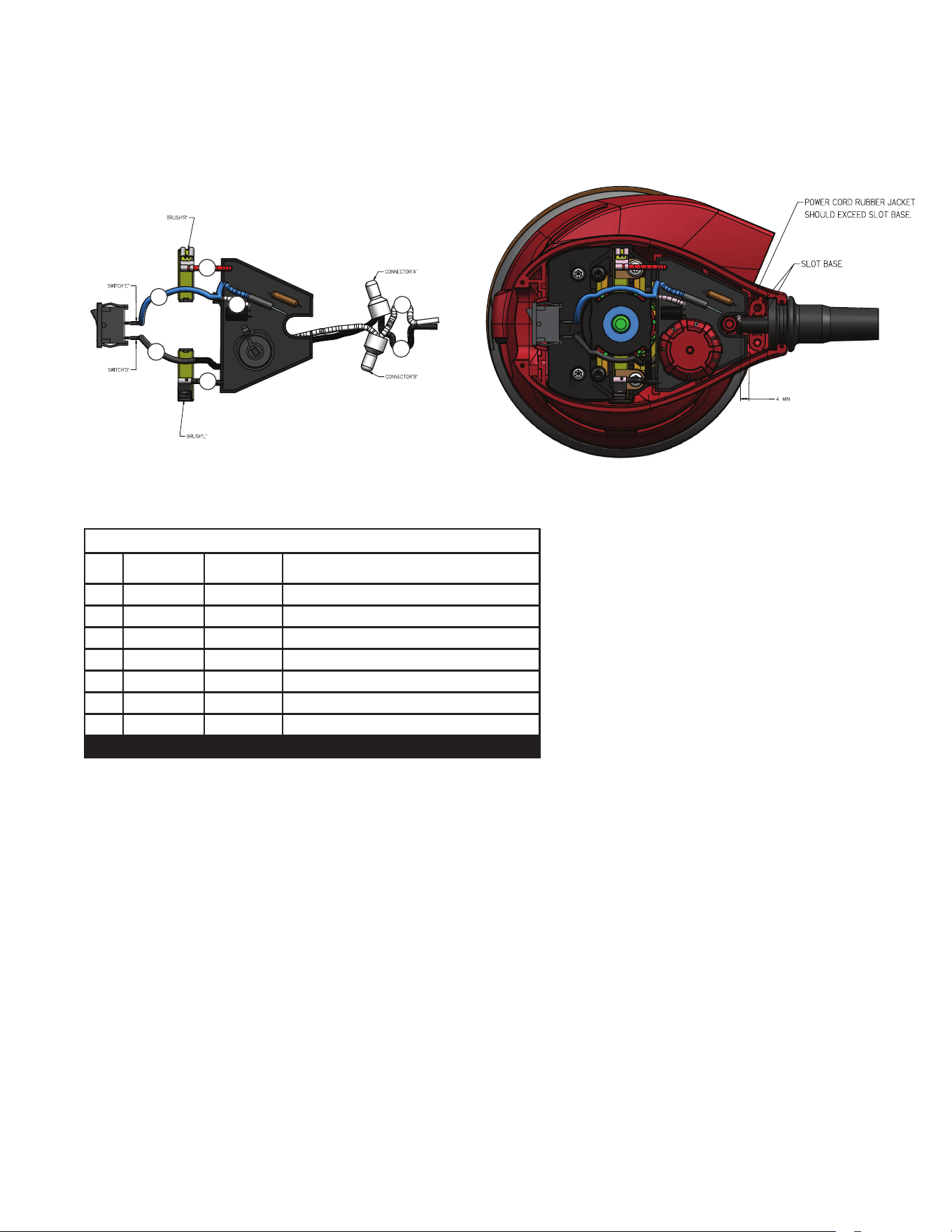
WIRING SPECIFICATIONS
Wire
No.
Wire
Color
Origin or
Gauge
Terminals, Connectors and 1 or 2 End Wire Preparation
1 White 22-64-1210 Power Cord
2 Black 22-64-1210 Power Cord
3 Blue 14-20-0185 PCBA Assembly
4 White 14-20-0185 PCBA Assembly
5 Red 14-20-0185 PCBA Assembly
6 Black 14-20-0185 PCBA Assembly
7 Black 23-66-0245 Switch
BULK LEAD WIRE - BULLETIN 58-01-0003
NOTE:
As an aid to reassembly, take note of the wire routings and position of the wires in the wire guides and wire guides traps prior to dismantling the tool.
Watch for pinched wires when placing the handle cover back over the housing assembly.
WIRING INSTRUCTIONS
1
2
3
4
5
6
7