
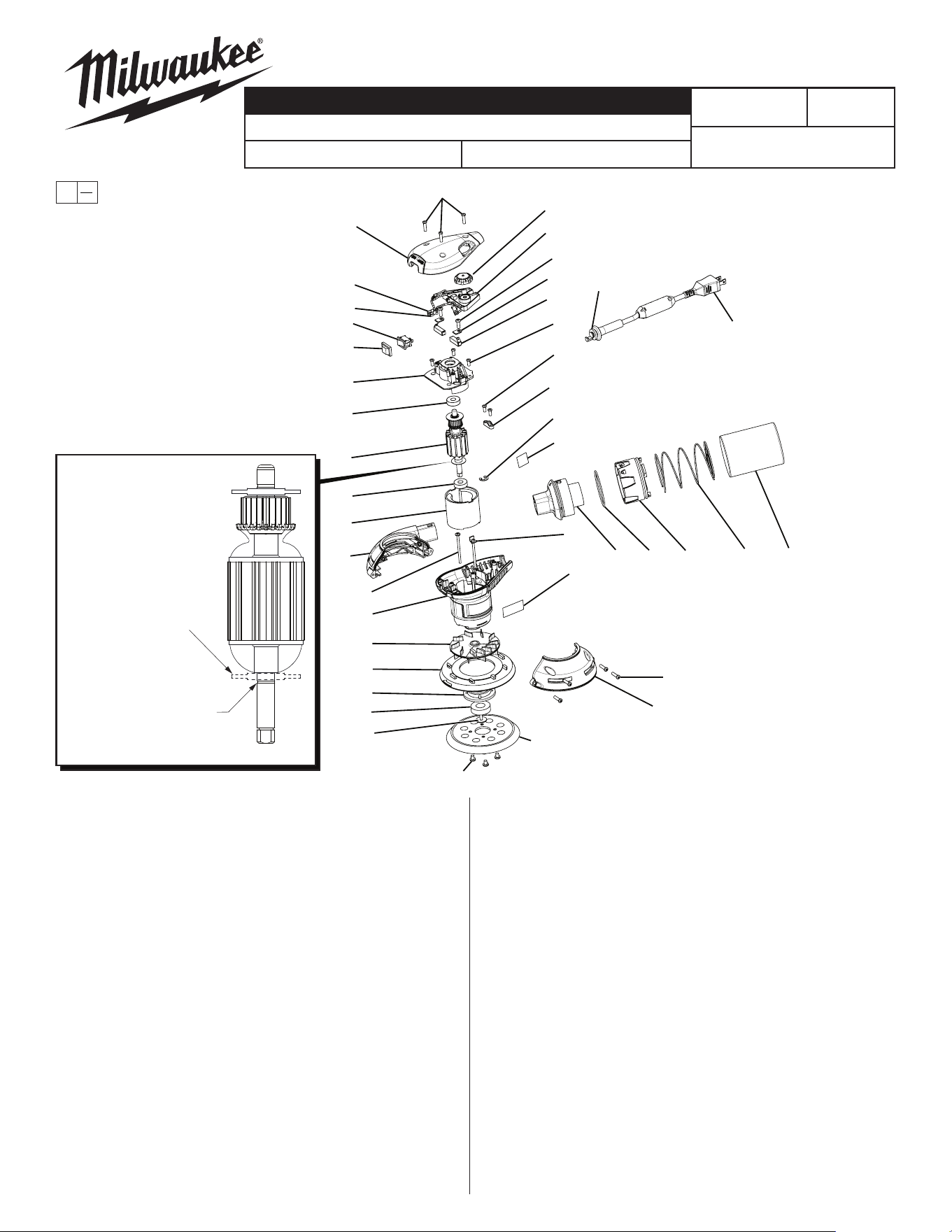
SPECIFY CATALOG NO. AND SERIAL NO. WHEN ORDERING PARTS
5" Random Orbit Sander
CATALOG NO. 6021-21
54-38-0390
SERVICE PARTS LIST
BULLETIN NO.
B19A
REVISED BULLETIN
DATE
June 2023
WIRING INSTRUCTION
SEE REVERSE
STARTING
SERIAL NUMBER
FIG. PART NO. DESCRIPTION OF PART NO. REQ.
1 02-04-5160 Bearing 1
2 02-04-5165 Bearing 2
3 06-81-0120 Screw w/Washer, Torx, T25, 1
10-32 UNF-2A x 1/2"
4 06-81-0130 Screw, Torx, T20 2
5 06-81-0135 Screw, Torx, T20 4
6 06-81-0140 Screw, Torx, T20 2
7 06-81-0145 Screw, Torx, T15 7
8 06-81-0150 Screw, Torx, T15 2
9 06-81-0155 Screw, Torx, T25 4
10 10-98-6045 Multilingual Warning Label 1
11 12-20-6045 Name Plate 1
12 14-20-0185 PCB Board 1
13 16-10-0631 Armature 1
14 18-10-0141 Field 1
15 22-18-1170 Carbon Brush Assembly w/Shunt Wire 2
16 22-38-0180 Brush Clamp 2
17 22-64-1210 Cord 1
18 22-75-0090 Speed Control Knob 1
19 22-84-0980 Fan 1
20 23-66-1661 Switch 1
21 23-94-1265 Black Switch Wire Harness 1
22 23-94-1270 Brown Switch Wire Harness 1
23 28-12-0365 Bearing Cap 1
24 31-12-0405 Plastic Bearing Cap 1
25 31-12-0410 Cap with Overmold 1
FIG. PART NO. DESCRIPTION OF PART NO. REQ.
26 31-15-1525 Dust Chute (See Note) 1
27 31-15-1530 Lower Housing Dust Chute Cover
(See Note) 1
28 31-15-1535 Lower Housing Cover 1
29 31-17-0530 Cord Clamp 1
30 31-50-2120 Motor Housing 1
31 31-58-0690 Dust Bag Locking Ring 1
32 34-40-1870 Dust Chute O-Ring 1
33 42-16-0570 Dust Bag 1
34 42-38-0405 Switch Boot 1
35 42-70-1005 Field Retaining Clip 2
36 44-52-0965 Brake Pad 1
37 44-76-0315 Strain Relief 1
38 44-86-1380 Retaining Ring 1
39 40-50-1110 Compression Spring 1
40 51-36-7100 Hook-and-Loop Sanding Disc Assembly 1
41 22-56-0150 Wire Connector 2
42-55-6022 Carrying Case (Not Shown) 1
NOTE: Items 26 and 27 t together with a one-time snap. When replacing
one piece, you must replace the other.
00
0
EXAMPLE:
Component Parts (Small #)
Are Included When Ordering
The Assembly (Large #).
9
40
3
1
23
36
19
30
4
27
14
2
13
2
24
34
20
21
22
25
7
18
12
6
16
15
5
8
29
38
10
35
11
28
7
26
32
31
39
33
17
37
NOTE: The service replace-
ment armature may or may
not have a disc washer in
this area. It has been
determined that a disc here
is not required.
When installing a new
service armature, remove
the existing ‘C’ ring (#38)
from the old armature and
place it on the shaft groove
of the new armature prior to
seating the ball bearing on
the shaft.
MILWAUKEE TOOL
l
www.milwaukeetool.com
13135 W. LISBON RD., BROOKFIELD, WI 53005
Drwg. 6
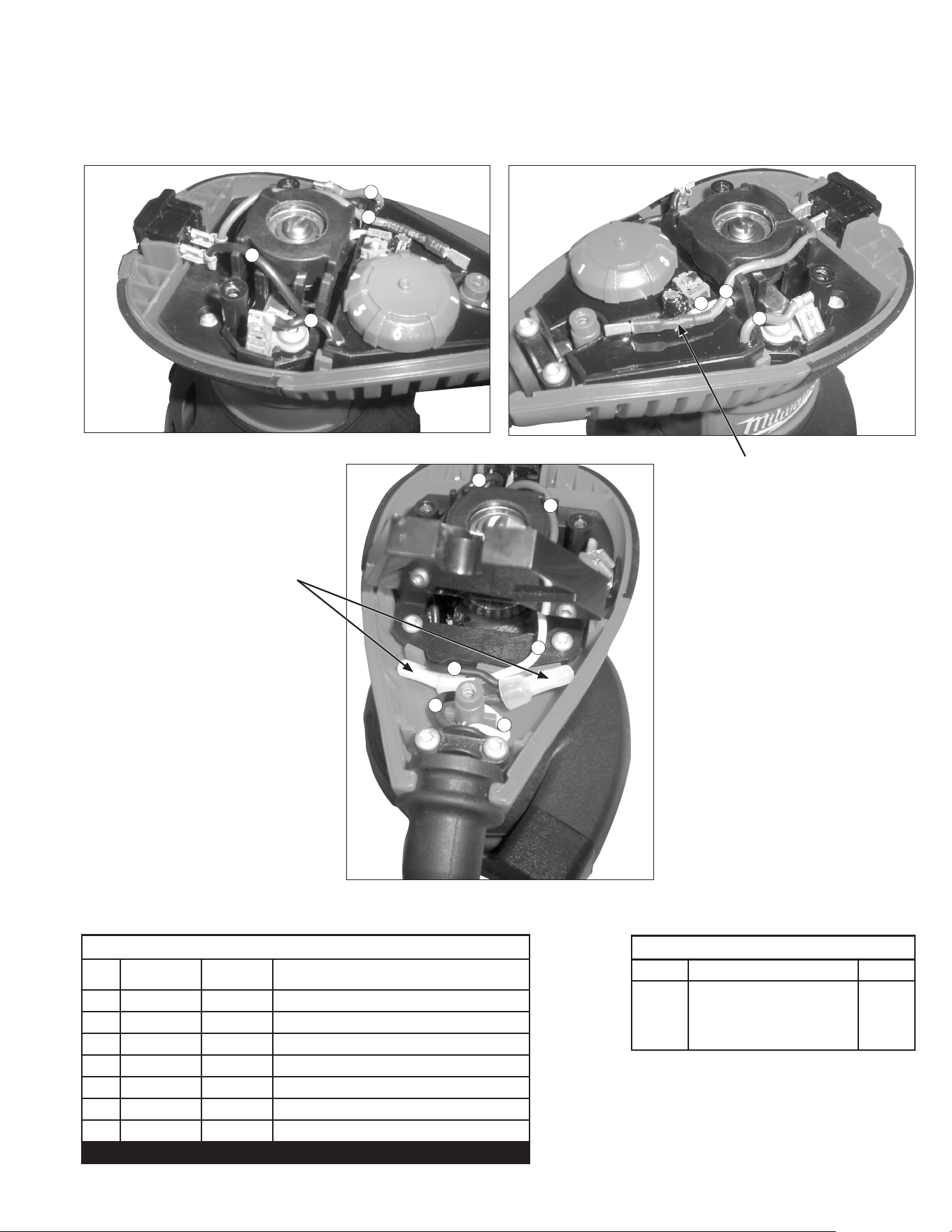
NOTE:
As an aid to reassembly, take note of the wire routings and position of the wires in the wire guides and wire guides traps prior to dismantling the tool.
Watch for pinched wires when placing the handle cover back over the housing assembly.
WIRING SPECIFICATIONS
Wire
No.
Wire
Color
Length Terminals, Connectors and 1 or 2 End Wire Preparation
1 Red -------- Component of PCB
2 Black -------- Component of Cord
3 Black -------- Component of PCB
4 Brown -------- Switch Wire Harness
5 Black -------- Switch Wire Harness
6 White -------- Component of PCB
7 White -------- Component of Cord
BULK LEAD WIRE - BULLETIN 58-01-0003
TERMINAL DESCRIPTION
Code Part No. Qnty.
NOTE:
All leads must be held to ± 1/16".
All lead lengths are before stripping.
Add .8" of Shrink Tube (ø 5 mm).
WIRING INSTRUCTIONS
1
3
2
5
4
4
1
4
5
5
6
6
7
Use Wire Connectors 22-56-0150 to connect
wire 2 to wire 5 and connect wire 6 to wire 7.