
© 2024 GeoVision, Inc. All rights reserved.
Under the copyright laws, this manual may not be copied, in whole or in part,
without the written consent of GeoVision.
Every effort has been made to ensure that the information in this manual is
accurate. GeoVision, Inc. makes no expressed or implied warranty of any kind
and assumes no responsibility for errors or omissions. No liability is assumed
for incidental or consequential damages arising from the use of the information
or products contained herein. Features and s
pecifications are subject to
change without notice.
GeoVision, Inc.
9F, No. 246, Sec. 1, Neihu Rd.,
Neihu District, Taipei, Taiwan
Tel: +886-2-8797-8377
Fax: +886-2-8797-8335
http://www.geovision.com.tw
Trademarks used in this manual: GeoVision, the GeoVision logo and GV
series products are trademarks of GeoVision, Inc. Windows is the registered
trademark of Microsoft Corporation.
November2024
Scan the following QR codes for product warranty and technical support
policy:
[Warranty] [Technical Support Policy]

i
Contents
Regulatory Notices ...................................................... 1
Preface .......................................................................... 2
Recognition and Authentication Considerations ..... 3
Important Notices for V1 ............................................. 5
Note for Wiegand Connection .................................... 5
Chapter 1 Introduction ............................................... 6
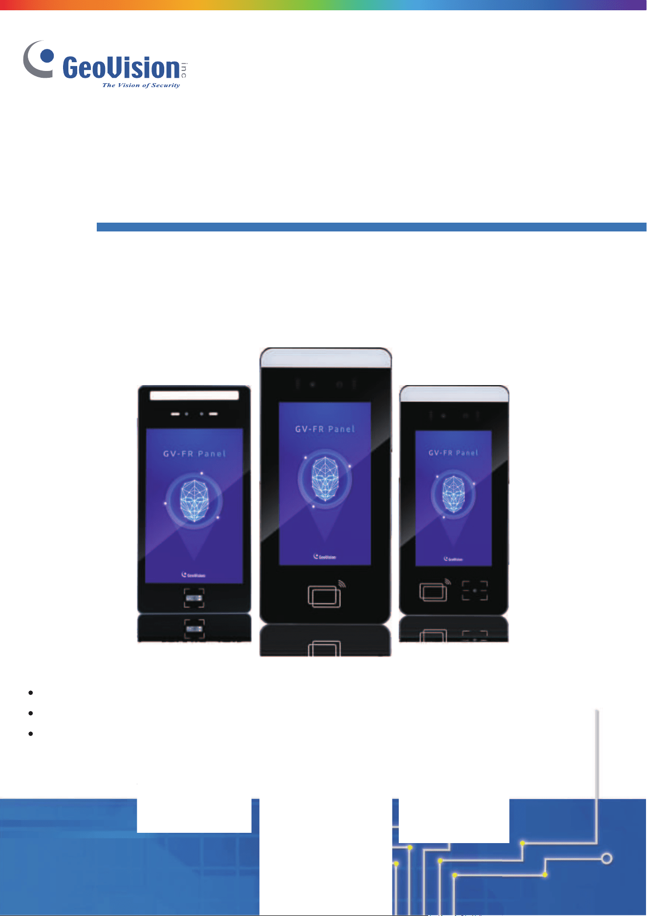
GV-FR Panel V1 ..................................................................................................... 6
GV-FR Panel V2 ..................................................................................................... 7
1.1 Packing List ............................................................................................................. 8
1.1.1 GV-FR Panel V1 ........................................................................................... 8
1.1.2 GV-FR Panel V2 ........................................................................................... 9
1.2 Firmware and Software Compatibility .....................................................................10
1.2.1 GV-FR Panel V1 ......................................................................................... 10
1.2.2 GV-FR Panel V2 ......................................................................................... 11
1.3 Overview ................................................................................................................12
1.3.1 GV-FR Panel V1 ......................................................................................... 12
1.3.2 GV-FR Panel V2 ......................................................................................... 14
1.4 Connecting GV-FR Panel .......................................................................................16
1.4.1 GV-FR Panel V1 ......................................................................................... 16
1.4.2 GV-FR Panel V2 ......................................................................................... 17
1.5 Standard Installation ...............................................................................................18
1.5.1 GV-FR Panel V1 ......................................................................................... 18
1.5.2 GV-FR Panel V2 ......................................................................................... 20
Chapter 2 Getting Started ........................................ 26
2.1 Accessing GV-FR Panel .........................................................................................26
2.2 Looking up the IP Address......................................................................................28
2.3 Local Settings .........................................................................................................30
Chapter 3 Access Control Integration .................... 36

ii
3.1 Setting up GV-ASManager .....................................................................................37
3.1.1 Adding GV-Controller .................................................................................. 37
3.1.2 Setting GV-FR Panel to be a Door .............................................................. 39
Chapter 4 User Management on GV-ASManager and
GV-FR Panel ............................................................... 42
4.1 Adding User Faces & Cards on GV-ASManager ....................................................43
4.2 Uploading to GV-FR Panel .....................................................................................46
4.3 Using GV-FR Panel ................................................................................................48
4.3.1 Face Only Mode .......................................................................................... 48
4.3.2 Card or Face Mode ..................................................................................... 49
4.3.3 Card + Face Mode ...................................................................................... 49
Chapter 5 Administrator Mode ................................ 50
5.1 General Settings .....................................................................................................51
5.1.1 System Settings .......................................................................................... 51
5.1.2 Account & Authority ..................................................................................... 53
5.1.3 Recognition Settings ................................................................................... 54
5.1.4 Relay Settings ............................................................................................. 56
5.2 Face Management .................................................................................................57
5.2.1 Face Profiles ............................................................................................... 57
5.3 Notify Settings ........................................................................................................60
5.3.1 GV-FWC/Controller ..................................................................................... 60
5.3.2 Event Trigger .............................................................................................. 61
5.4 Event Query ...........................................................................................................63
5.4.1 Detail Log .................................................................................................... 63
5.4.2 Exported Files ............................................................................................. 64
Chapter 6 Advanced Applications .......................... 65
6.1 Upgrading System Firmware ..................................................................................65
6.2 Restoring to Factory Default Settings .....................................................................67
6.3 GV-Face Manager for Face Database Management ..............................................68
Chapter 7 Third-Party Controller Integration ......... 70
7.1 Via the Wiegand Interface ......................................................................................71

iii
7.2 Via the GV-FWC Converter ....................................................................................73
Chapter 8 Live Streaming on GV-Software ............. 76
Appendix .................................................................... 78
Verifying the Connection between GV-FR Panel and GV-AS Controller ........................78
Optional Installation for GV-FR Panel V1 ......................................................................79
GV-Mount800 ....................................................................................................... 79
GV-Mount801 ....................................................................................................... 81
GV-Mount920 ....................................................................................................... 90
1
Regulatory Notices
FCC Notice
This equipment has been tested and found to comply with the limits for a Class A digital
device, pursuant to part 15 of the FCC Rules. These limits are designed to provide
reasonable protection against harmful interference when the equipment is operated in a
commercial environment.
Class A
This equipment generates, uses, and can radiate radio frequency energy and, if not installed
and used in accordance with the instruction manual, may cause harmful interference to radio
communications. Operation of this equipment in a residential area is likely to cause harmful
interference in which case the user will be required to correct the interference at their own
expense.
CE Notice
This is a Class A product. In a domestic environment, this product may cause radio
interference in which case the user may be required to take adequate measures.
RoHS Compliance
The Restriction of Hazardous Substances (RoHS) Directive is to forbid the use of hazardous
materials of production. To meet the RoHS Directive requirements, this product is made to
be RoHS compliant.
WEEE Compliance
This product is subject to the Waste Electrical and Electronic Equipment (WEEE) Directive
and made compliant with the WEEE requirements.
2
Preface
Welcome to the GV-FR Panel User’s Manual.
This Manual is designed for the following models:
⚫ GV-FR Panel V1
Model
GV-FR Panel-5
GV-FR Panel-10
Event Log
50,000
100,000
⚫ GV-FR Panel V2
Model
GV-FR Panel V2
GV-FR Panel V2-QR
QR Code Reader
No
Yes
3
Recognition and Authentication Considerations
Face Recognition Distance:
• GV-FR Panel delivers optimal face recognition results when the faces of the targets are
within 1 m (3.3 ft) of GV-FR Panel V1, and 2 m (6.6 ft) of GV-FR Panel V2.
Lighting Conditions:
• GV-FR Panel is designed for indoor use only. Avoid exposing it to direct sunlight as it
may affect its face recognition performance.
Face Recognition Limitations:
• GV-FR Panel may not be able to recognize faces wearing any type of sunglasses.
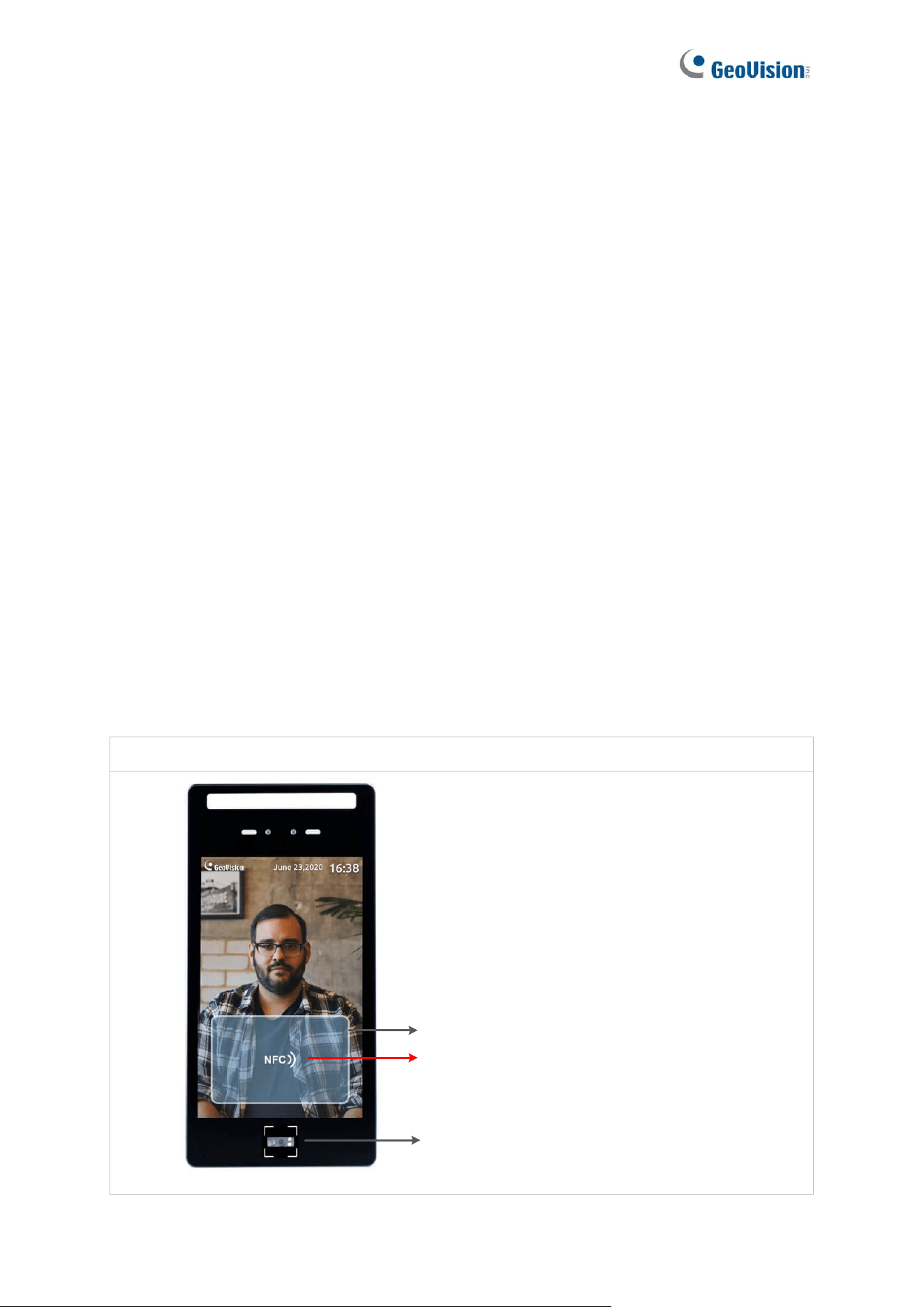
Detection Area of Cards, Tags / Fobs, QR Codes:
• When swiping cards, place them closely against the touch screen for optimal detection
effect.
• Only available for GV-FR Panel V1. When swiping tags / fobs, place them closely
against the text “NFC” on the touch screen for optimal detection effect.
• When scanning QR codes, keep a distance of 10-15 cm (4-6 in) from the reader for
effective scanning.
GV-FR Panel V1:
Detection Area for Card
Place tags / fobs closely against the text “NFC”
QR code reader

4
GV-FR Panel V2:
GV-FR Panel V2-QR:

5
Important Notices for V1
1. GV-FR Panel V1 will automatically load default when downgraded to an older version.
2. After upgrading to V1.20, make sure to set the network setting to DHCP and connect
the panel to Internet for license authentication.
3. After upgrading to version V1.20, a loading screen displaying “Data migration” will
appear and face recognition will remain non-functional until the system completes
upgrading.
Note for Wiegand Connection
When connecting via Wiegand, the Ground (GND) wire must be connected alongside the
Wiegand Data wires.
6
Chapter 1 Introduction
GV-FR Panel V1
GV-FR Panel V1 is a face-recognition-based access reader, with an 8" LCD touchscreen that
displays 800 x 1280 HD images. When connected to GeoVision access control systems, GV-
FR Panel V1 can grant or deny access based on a variety of credentials including face
recognition, access cards and card + face double authentication. Additionally, GV-FR
Panel V1 can read QR codes from GV-ASManager's Visitor Management System (GV-
VMWeb) as well as the EU Digital COVID Certificate.
GV-FR Panel V1, with cutting-edge face recognition ability, can be integrated into any third-
party Wiegand access control system. It combines AI video analytics with access control to
provide a new level of convenience and security.
Models
Model
GV-FR Panel-5
GV-FR Panel-10
Event Log
50,000
100,000

7
GV-FR Panel V2
GV-FR Panel V2 is a face-recognition-based access reader with a 7" LCD touchscreen that
displays 600 x 1024 HD images. When connected to GeoVision access control systems, GV-
FR Panel V2 can grant or deny access using a number of credentials, including face
recognition, access cards, and card plus face double authentication. Additionally, GV-FR
Panel V2-QR can read QR codes from the GV-ASManager Visitor Management System
(GV-VMWeb). A guest can gain entrance to a regulated area by scanning the QR code
displayed on their mobile phone.
GV-FR Panel V2, with cutting-edge face recognition ability, can be integrated into any third-
party Wiegand access control system. It combines AI video analytics with access control to
provide a new level of convenience and security. Furthermore, its live view can be cast onto
GV-VMS, to build a more comprehensive surveillance management environment.
Models
GV-FR Panel V2
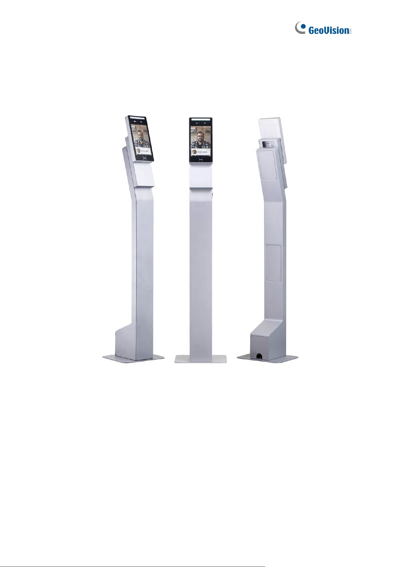
GV-FR Panel V2 with Pillar
Stand
with Pillar Stand
GV-FR Panel V2-QR
with QR Code Reader
GV-FR Panel V2-QR with
Pillar Stand
with QR Code Reader and Pillar Stand
8
1.1 Packing List
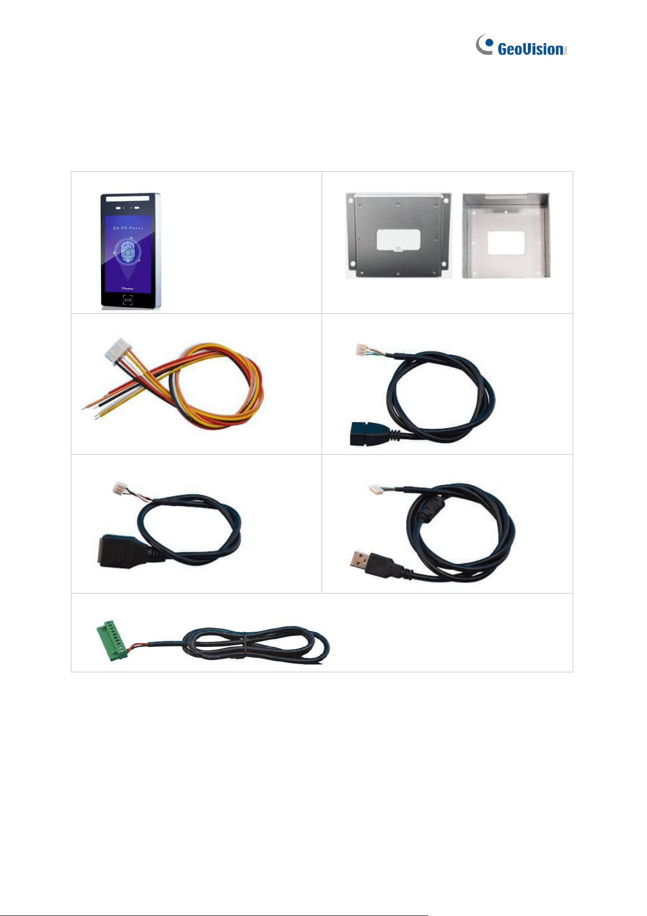
1.1.1 GV-FR Panel V1
1. GV-FR Panel V1
2. Wall Mount Bracket Kit
For GV-Mount800 For GV-Mount801
3. Wiegand cable
4. USB Host PH2.0-4P cable
5. RJ-45 cable
6. USB OTG PH2.0-4P cable
7. Power cable
9
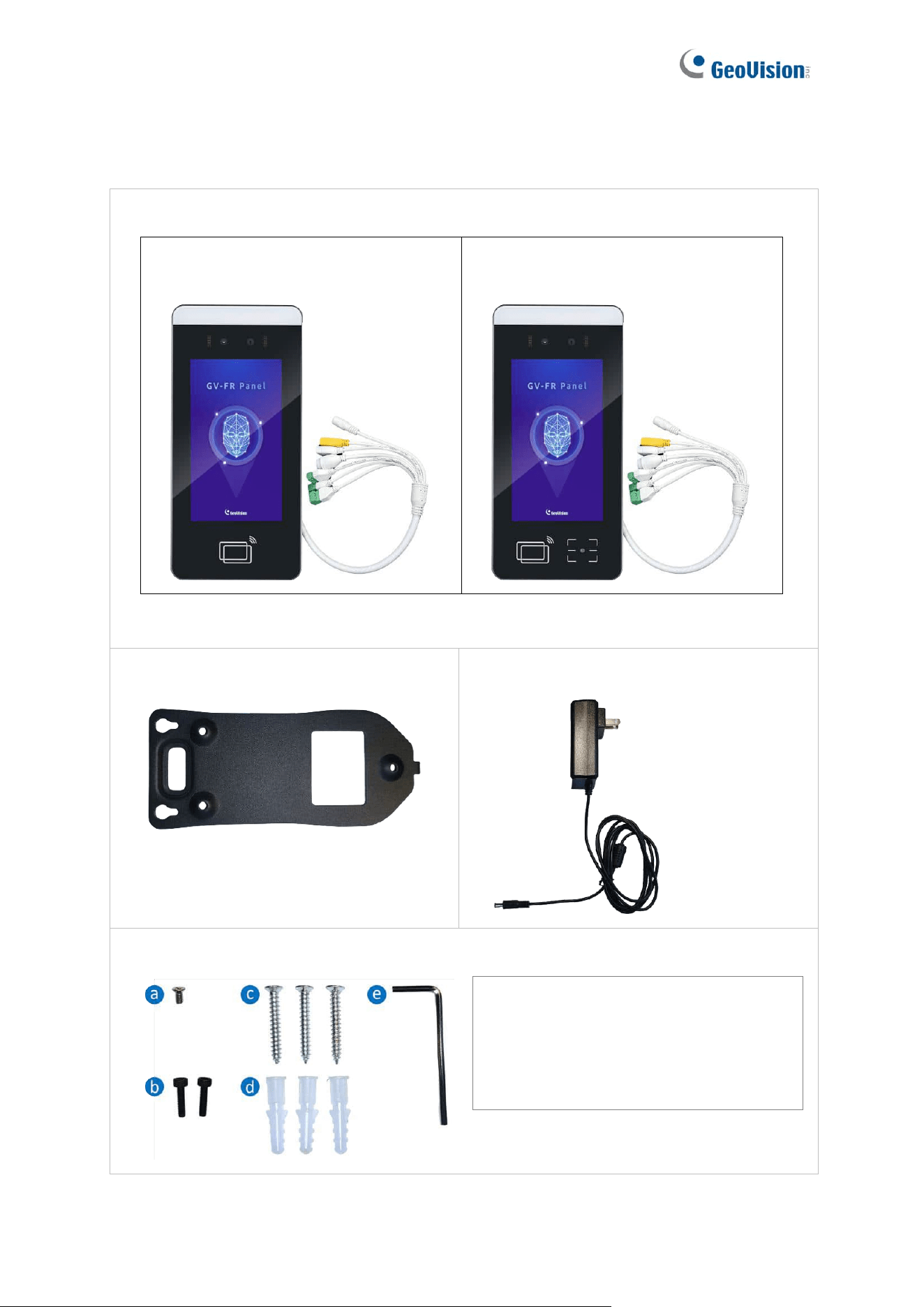
1.1.2 GV-FR Panel V2
1. GV-FR Panel V2 or GV-FR Panel V2-QR
GV-FR Panel V2 (includes the data
cable attached to the rear panel)
GV-FR Panel V2-QR (includes the
data cable attached to the rear panel)
2. Wall Mount Bracket Kit
3. Power Adapter DC 12V 3A
4. Screw Kit
(a) Short Screw (5 mm / 0.20 in) x 1
(b) Socket Screw (10 mm / 0.39 in) x 2
(c) Long Screw (29 mm / 1.14 in) x 3
(d) Plastic Anchor (29 mm / 1.14 in) x 3
(e) Allen Wrench x 1
10
1.2 Firmware and Software Compatibility
GV-FR Panel is compatible with the following firmware and software versions:
1.2.1 GV-FR Panel V1
Supported Product / Application
Version
Controller
GV-AS210 / 2110 / 2120
V2.31 or later
GV-AS410 / 4110 / 4111
GV-AS810 / 8110 / 8111
GV-AS1520
V2.06 or later
GV-AS1620
V1.03 or later
GV-CS1320
V3.05 or later
GV-EV48
V2.31 or later
GV-FWC access data converter
V1.02 or later
GV-ASManager access control software
V5.3.1 or later
GV-VMS
V17.4.8 / V18.3.5 or later
GV-Edge Recording Manager (Windows)
V2.2.0 or later
Face Enrollment
GV-ASManager (software) V5.3.1 or later,
GV-Face Manager (utility) V1.3.0 or later
GV-Face (mobile app) V2.1.0 or later
Firmware Upgrade
GV-IP Device Utility V8.9.3 or later
11
1.2.2 GV-FR Panel V2
Supported Product / Application
Version
Controller
GV-AS210 / 2110 / 2120
V2.60 or later
GV-AS410 / 4110 / 4111
GV-AS810 / 8110 / 8111
GV-AS1620
V1.13 or later
GV-CS1320
V3.13 or later
GV-EV48
V2.31 or later
GV-FWC access data converter
V1.02 or later
GV-ASManager access control software
V6.1.0 or later
GV-VMS
V17.4.8 / V18.3.5 or later
Face Enrollment
GV-ASManager (software) V6.1.0 or later,
GV-Face Manager (utility) V1.3.0 or later,
GV-Face (mobile app)
⚫ for Android V2.2.0 or later
⚫ for iOS V2.2.1 or later
Firmware Upgrade
GV-IP Device Utility V9.0.2 or later
12
1.3 Overview
1.3.1 GV-FR Panel V1
1
11
2
3
4
5
6
8
10
9
12
7
13
14
No.
Name
Function
1
LED Light
• White LED: Turns on LED lighting when its radar sensor
detects motion.
• Green LED: Turns on when recognizing registered faces.
• Red LED: Turns on when detecting unknown faces.
2
Built-in Cameras
Captures real-time live images at the front of the panel.
3
Touchscreen Panel
Displays the live images captured by the built-in cameras
and accesses its local settings.
4
QR Code Reader
Reads QR codes used for access control. (The QR code
LED turns on when detecting motion around.)
5
Rear Panel
Contains all the ports of the GV-FR Panel V1. (See No. 6 –
10.)
6
Reset Button
Restarts the GV-FR Panel V1.
7
Wiegand Port
Connects to 3
rd
-party controllers. (See Chapter 7 Third-Party
Controller Integration.)
8
USB OTG PH2.0-4P Port
Connects to a PC for data backup and/or firmware upgrade
via the supplied USB OTG PH2.0-4P cable.
(Currently not functional.)
9
USB Host PH2.0-4P Port
Connects to a USB keyboard or mouse via the supplied USB
Host PH2.0-4P cable.
10
RJ-45 Port
Connects to the network via the supplied RJ-45 cable.

13
11
Relay Output
Contains the following 3 relay pins: NO, COM, and NC.
12
2-Pin Power connector
Connects to power via the supplied 2-pin power cable and an
optional power adapter.
13
Microphone
Receives audio. (Enabled by default.)
14
Speaker
Sounds when typing the settings on the touchscreen, swiping
a card, and scanning the QR code.
Note: The SIM card slot and RS-485 and RS-232 ports are not functional.
14
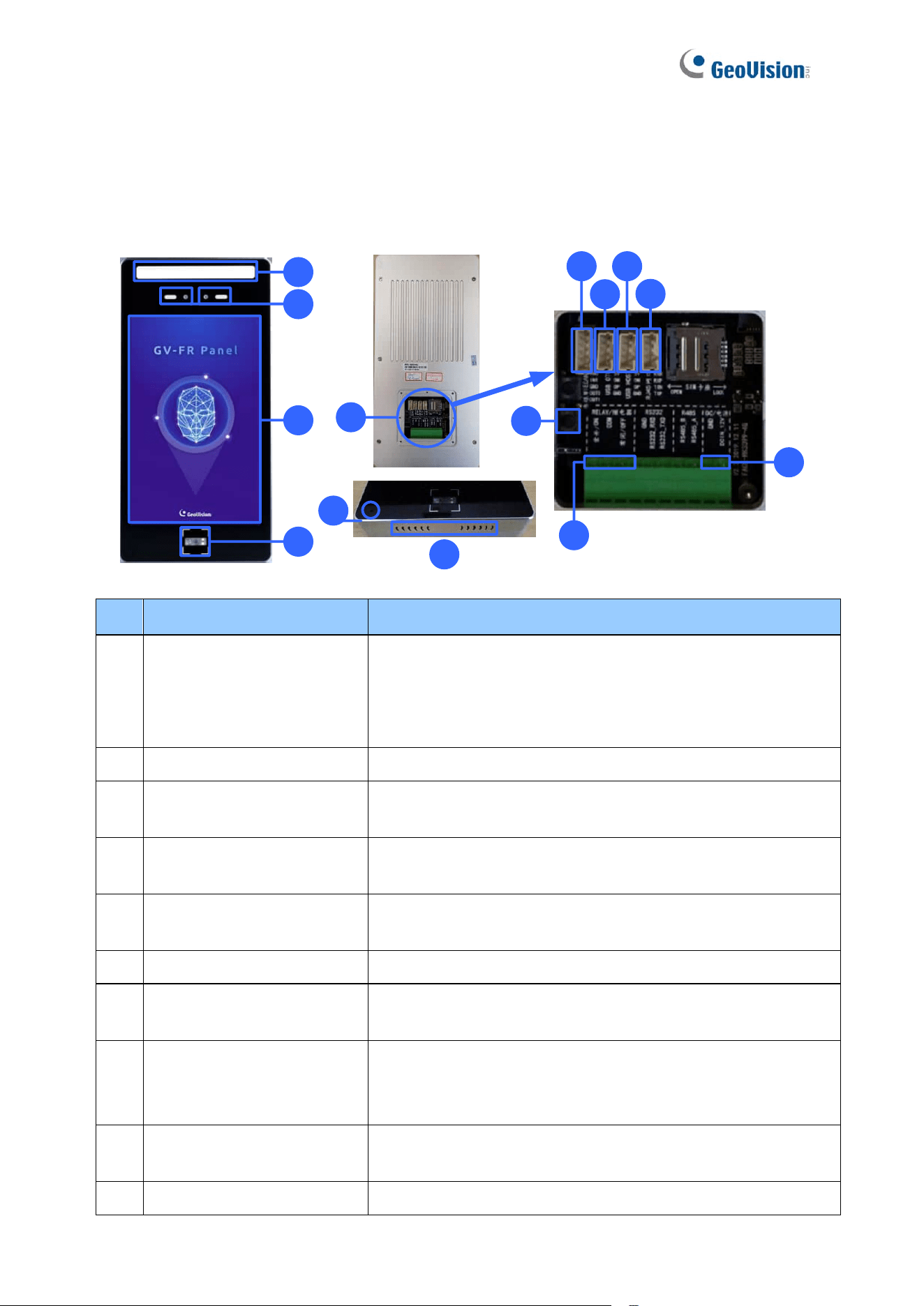
1.3.2 GV-FR Panel V2
No.
Name
Function
1
LED Light
• Green LED: Turns on when recognizing registered faces.
• Red LED: Turns on when detecting unknown faces.
2
Built-in Cameras
Captures real-time live images at the front of the panel.
3
Touchscreen Panel
Displays the live images captured by the built-in cameras
and accesses its local settings.
4
Card Reader
Reads ID cards or tags.
5
QR Code Reader
Reads QR codes used for access control.
6
Microphone
Receives audio.
7
Speaker
Sounds when playing the audio clip “Please wear a face
mask,” when users type the settings on the touchscreen,
swipe a card, scan the QR code, and when customer support
gives instructions remotely.
8
Data Cable
Contains all the ports of GV-FR Panel V2. (See No. 9 – 15.)
9
RJ-45 Port
Connects to the network using a user-supplied Ethernet
cable. (See 1.4 Connecting GV-FR Panel.)
15
10
Wiegand Output
Connects to 3
rd
-party controllers. (See Chapter 7 Third-Party
Controller Integration.)
Contains the following 5 pins:
1. 232-RX (Not functional.)
2. 232-TX (Not functional.)
3. Wiegand Output Data 0
4. Wiegand Output Data 1
5. GND
Note: The Wiegand Output pins (Data 0 and Data 1) and the
GND pin must be connected when integrating with a third-
party controller.
11
Wiegand Input
Contains the following 4 pins:
1. 12V (Not functional.)
2. GND (Not functional.)
3. Wiegand Input Data 1 (Not functional.)
4. Wiegand Input Data 0 (Not functional.)
12
Relay Output
Contains the following 2 relay pins: COM (+) and NO (-).
13
USB Host PH2.0-4P Port
Connects to a USB keyboard or mouse.
14
Power Input
Connects to power using the supplied power adapter. (See
1.4 Connecting GV-FR Panel.)
15
USB OTG PH2.0-4P Port
Not functional.
16
1.4 Connecting GV-FR Panel
1.4.1 GV-FR Panel V1
To connect GV-FR Panel V1, follow the steps below.
1
2
1. Connect the GV-FR Panel V1 to the network using the supplied RJ-45 cable with a user-
supplied Ethernet cable.
2. Connect the GV-FR Panel V1 to power using the supplied 2-pin power cable and an
optional power adapter.
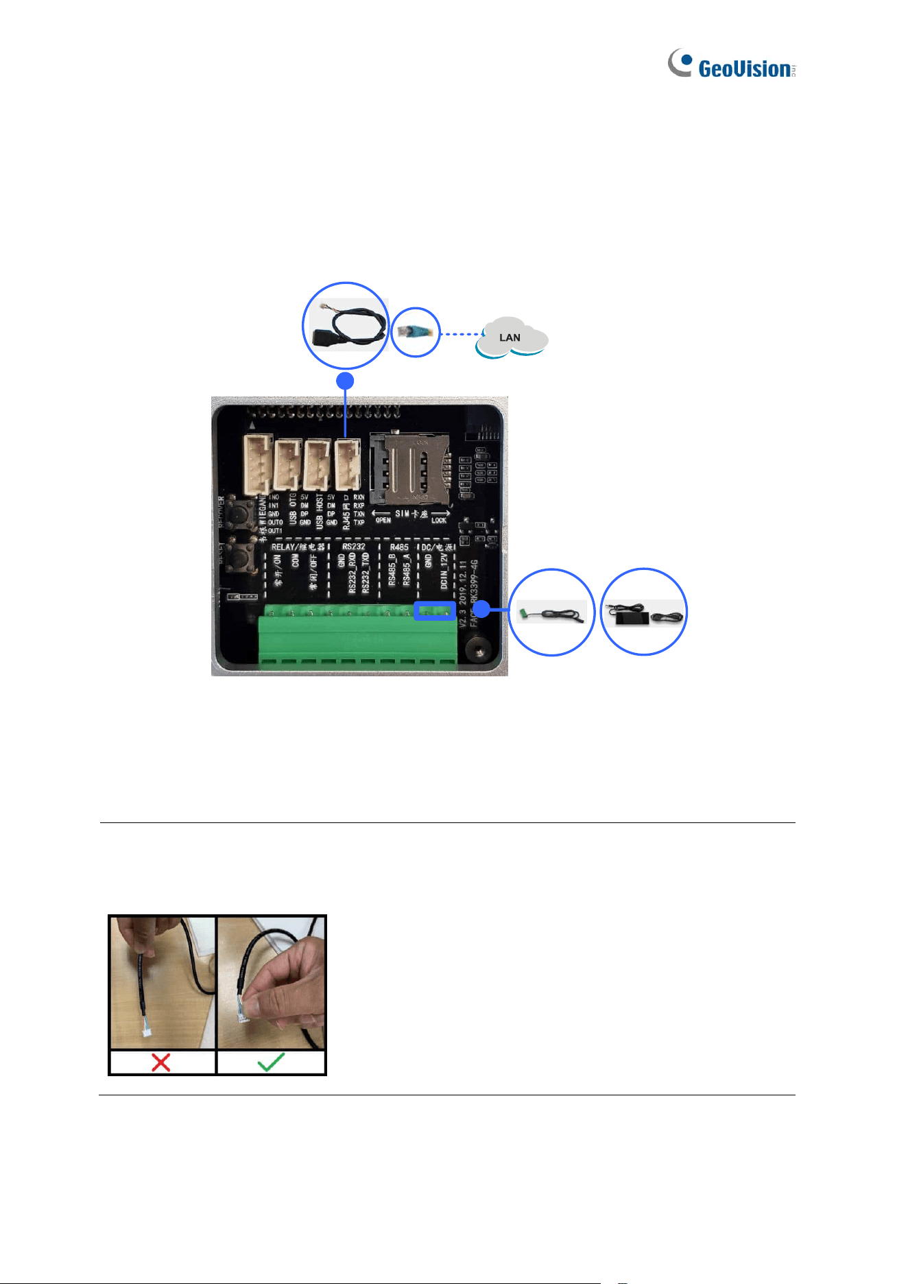
Note: When unplugging a connected cable (No. 3 / 4 / 5 / 6 / 7, 1.2 Packing List) from GV-
FR Panel V1 for any reason, grip firmly onto the terminal block and pull out slowly. Do not
pull the cable by the cord.
Upon first-time starting GV-FR Panel V1, users are prompted to set the login password for its
Administrator account. After the password is set, the live view of the GV-FR Panel V1’s built-
in camera appears. For details, see Chapter 2 Getting Started.
17
1.4.2 GV-FR Panel V2
To connect GV-FR Panel V2, follow the steps below.
LAN
Power
1
2
1. To connect GV-FR Panel V2 to power, connect from the power input of the data cable to
power using the supplied power adapter.
2. To connect GV-FR Panel V2 to the network, connect from the RJ-45 port of the data
cable to the network using a user-supplied Ethernet cable.
See 1.3 Overview for details on the data cable.
Upon first-time starting GV-FR Panel V2, users are prompted to set the login password for its
Administrator account. After the password is set, the live view of the GV-FR Panel V2’s built-
in camera appears. For details, see Chapter 2 Getting Started.
18
1.5 Standard Installation
1.5.1 GV-FR Panel V1
For installing GV-FR Panel V1 on a wall, follow the steps below.
1. Place the mounting bracket on the wall and mark the locations of the 4 screw positions
as illustrated below.
Facing the side to the groud
2. At each of the 4 screw positions marked on the wall, drill a hole slightly smaller than the
plastic screw anchors provided.
3. Insert the 4 plastic screw anchors into the holes drilled and secure the mounting bracket
onto the wall with the screws provided.
4. Secure the large sealing rubber and the back cover onto the back of the GV-FR Panel
V1 with the screws provided.
Sealing Rubber
Back Cover
Note: Thread the necessary cables through the back cover and connect them to the
panel before securing the cover.
Facing the side to the ground
19
5. Secure the small sealing rubber and the mounting plate onto the GV-FR Panel V1 with
the screws provided.
Sealing Rubber
Mounting Plate
6. Secure the GV-FR Panel V1 onto the wall by attaching its mounting plate onto the wall
mount bracket.
The Mounting Plate secured
at the back of GV-FR Panel
The Wall Mount Bracket
fixed on the wall
7. Insert a screw onto each side of the wall mount to secure and complete the installation.
20
1.5.2 GV-FR Panel V2
1.5.2.1 Wall Installation
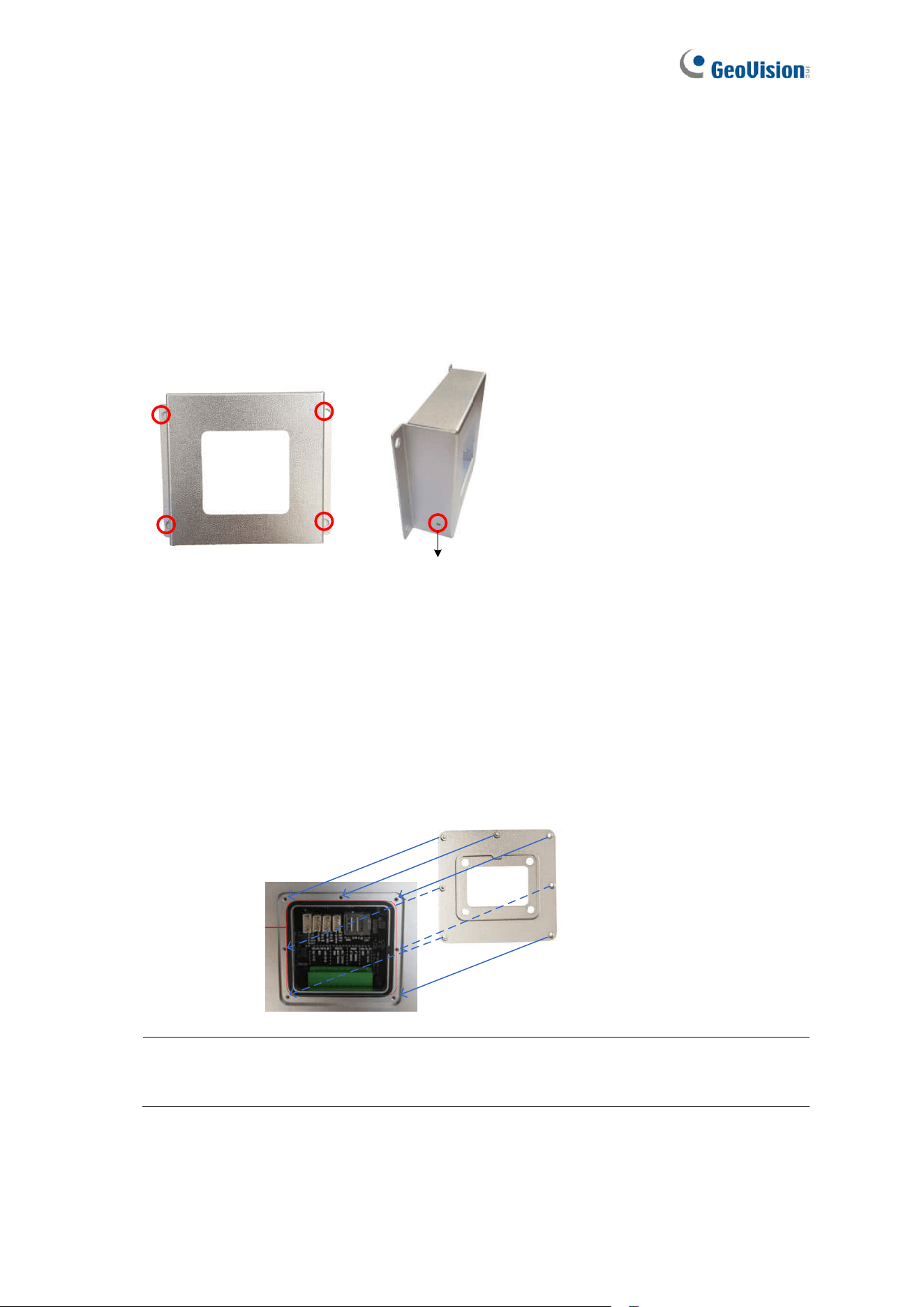
To install GV-FR Panel V2 on a wall, follow the steps below.
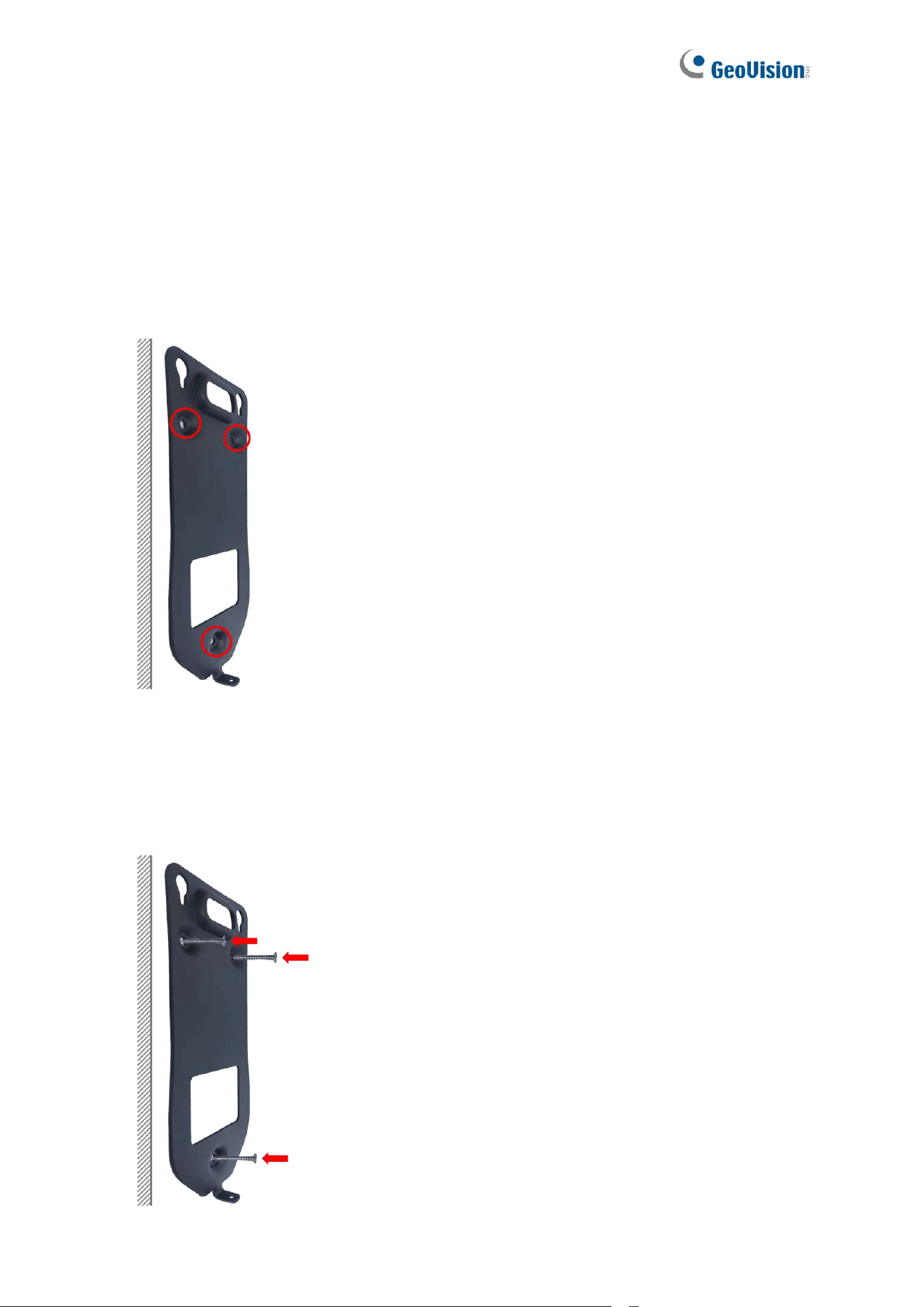
1. Place the mounting bracket on the wall and mark the locations of the three screw
positions as illustrated below.
2. At each of the three screw positions marked on the wall, drill a hole using a 6 mm (0.24 in)
drill bit. The depth should be 35 to 40 mm (1.38 to 1.57 in).
3. Insert three of the provided plastic anchors into the holes drilled, and then secure the
mounting bracket onto the wall with three of the provided 29 mm (1.14 in) screws.
21
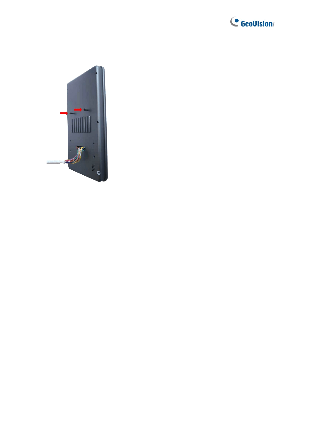
4. Secure two of the provided 10 mm (0.39 in) socket screws to the back of GV-FR Panel
V2. The provided Allen wrench can be used if needed.
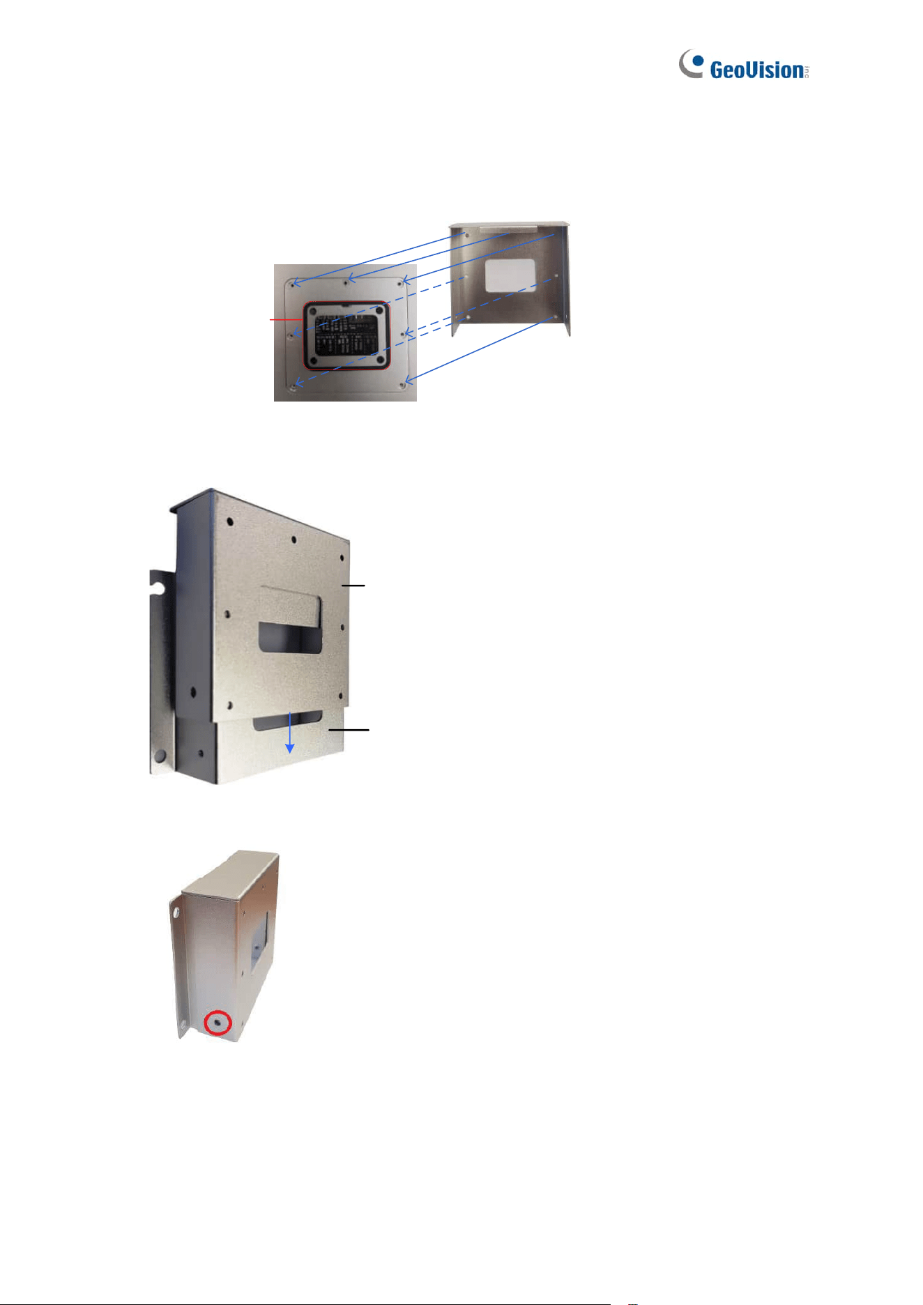
5. If a wall hole is drilled to conceal the cables, guide the data cable attached to GV-FR
Panel V2 through the square hole in the mounting bracket and into the wall; if not, let it
hang down from the panel without passing through the bracket. Align the two socket
screws on the panel with the holes at the top of the bracket, allowing the panel to hang
securely on the bracket.
22
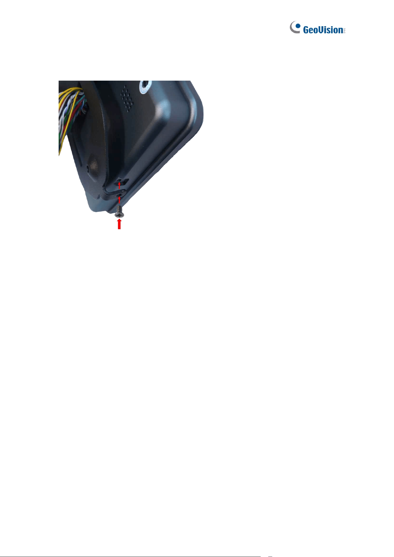
6. To complete the installation, secure the mounting bracket to GV-FR Panel V2 from the
bottom using one of the provided 5 mm (0.20 in) screws.
23
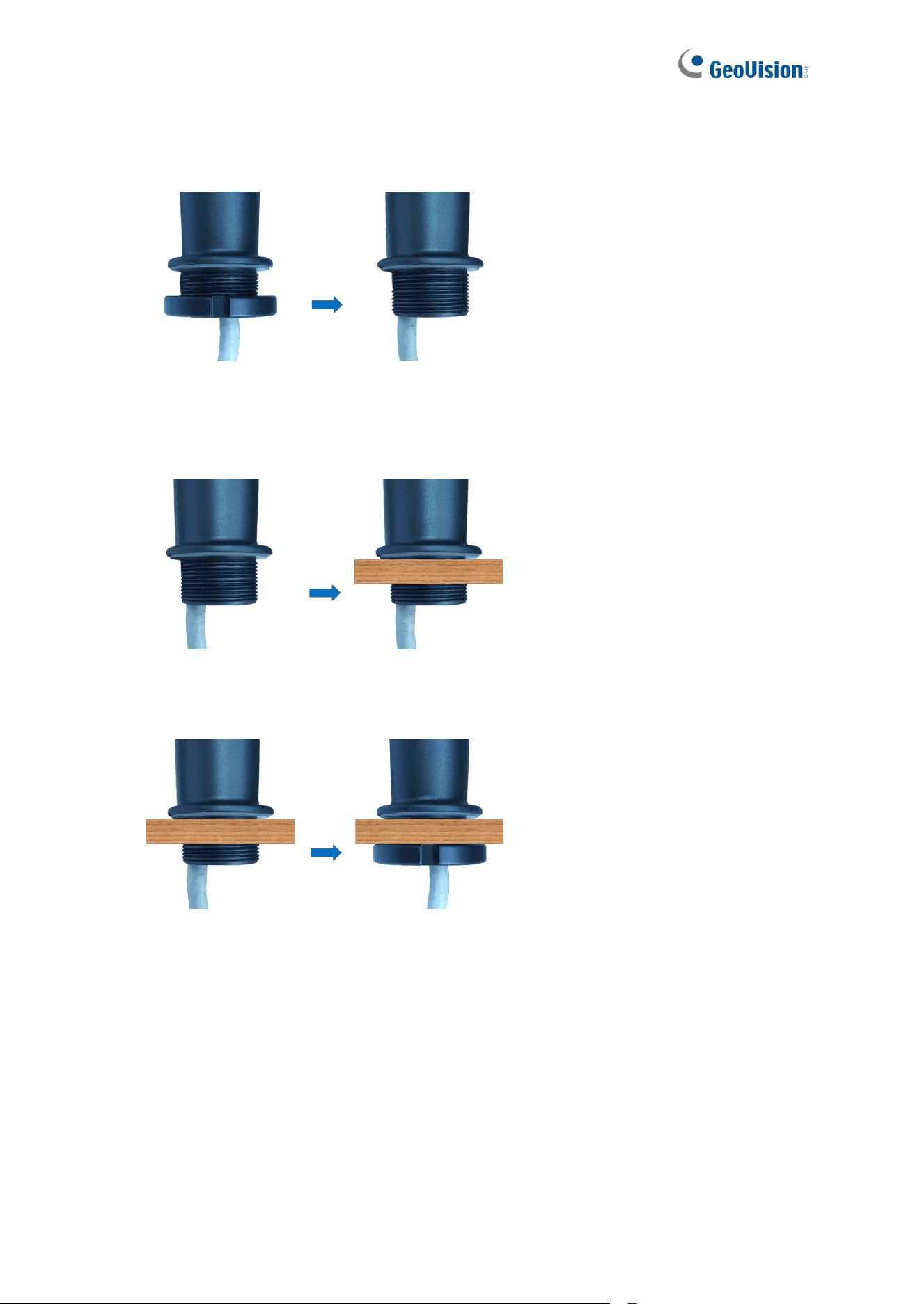
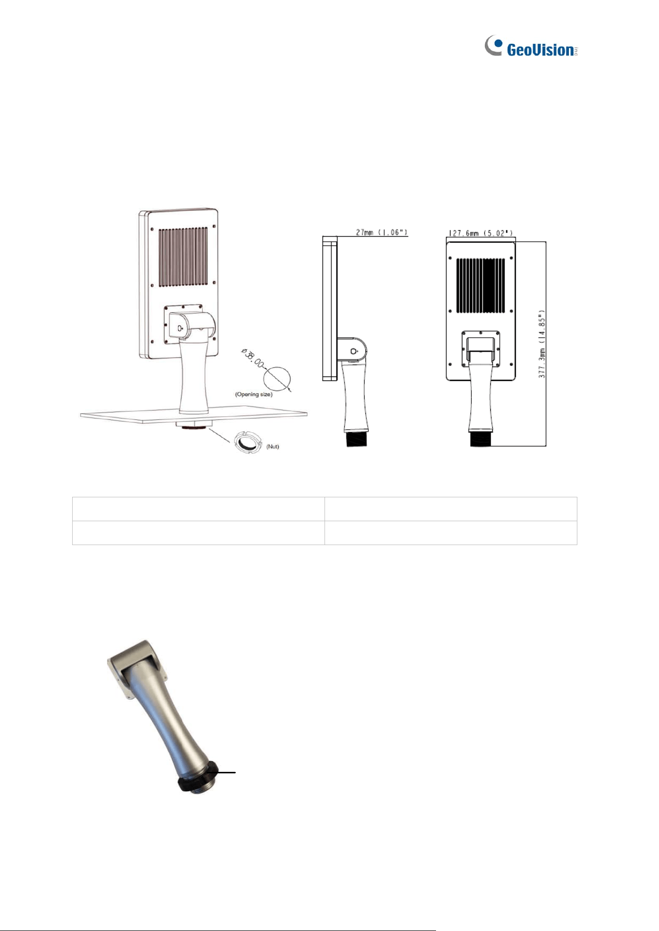
1.5.2.2 Desktop Installation
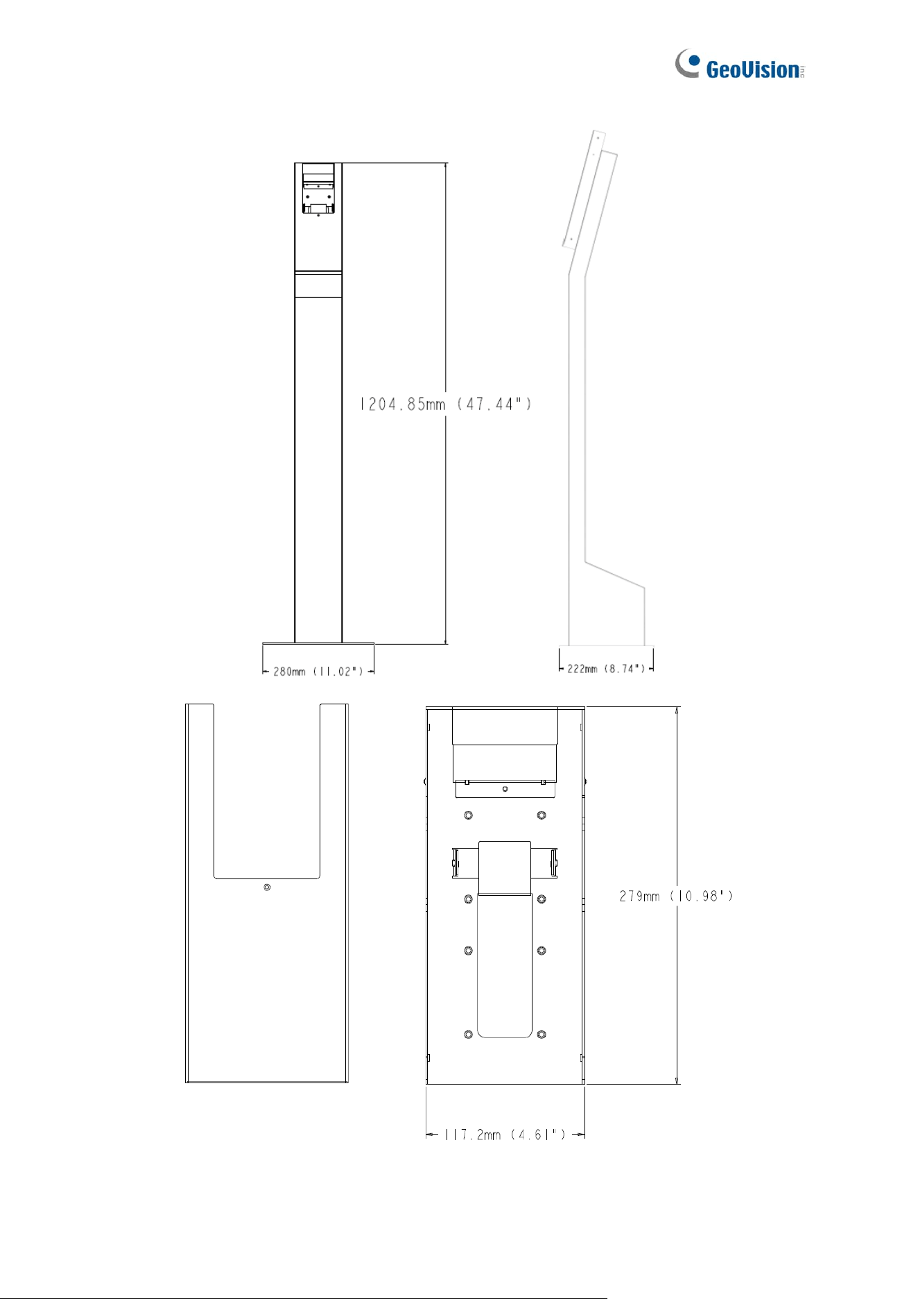
To install GV-FR Panel V2 with Pillar Stand on a horizontal surface (such as a counter or
desk), follow the steps below.
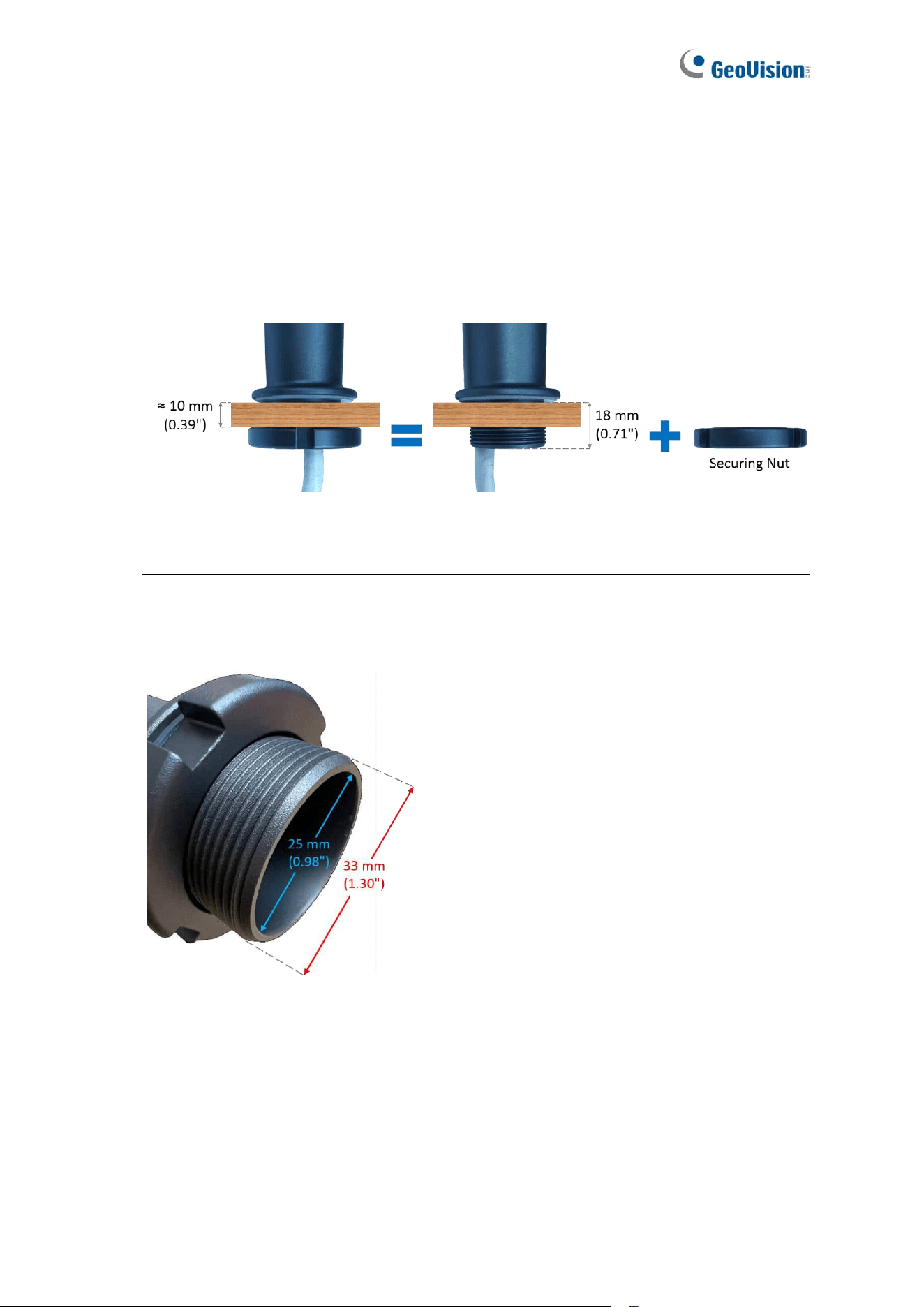
1. Select a suitable horizontal surface no thicker than approximately 10 mm (0.39 in).
leaving space for the securing nut along the 18 mm (0.71 in) thread.
Note: The 10 mm (0.39 in) measurement is an estimate; use your discretion when
selecting the surface.
2. Drill a hole in the surface to fit the pillar stand. The hole should be slightly larger than
the stand’s outer diameter of 33 mm (1.30 in) to allow smooth insertion.
24
3. Detach the securing nut from the end of the pillar stand. Slide the nut along the length of
the cables until it is fully removed.
4. Route the cables through the drilled hole, and then insert the pillar stand (already
attached to the back of GV-FR Panel V2) through the hole until the stand sits firmly on
the surface.
5. On the opposite side of the surface, thread the cables through the securing nut, and
then screw the nut onto the end of the pillar stand until the stand is securely mounted.
25
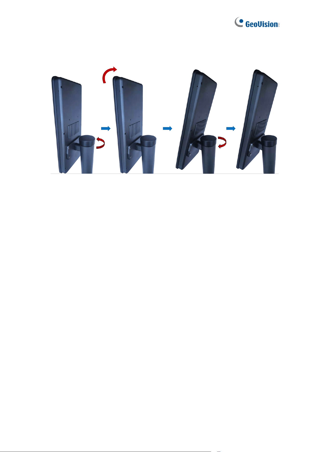
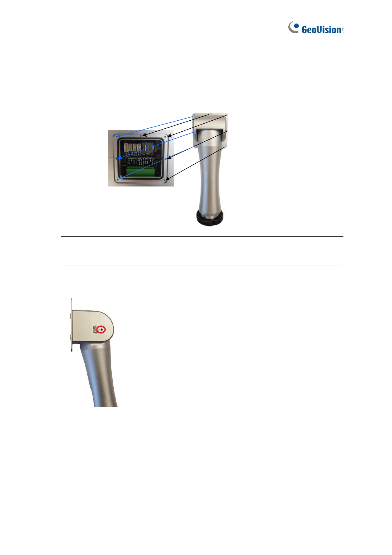
6. Adjust the tilt angle of GV-FR Panel V2 by loosening the cover on top of the pillar stand.
Once you have adjusted the angle, re-tighten the cover to lock the tilt angle in place.
26
Chapter 2 Getting Started
This chapter guides first-time users in accessing the GV-FR Panel and checking the IP
address of GV-FR Panel in order to access it through a Web browser, as well all describing
its local settings.
2.1 Accessing GV-FR Panel
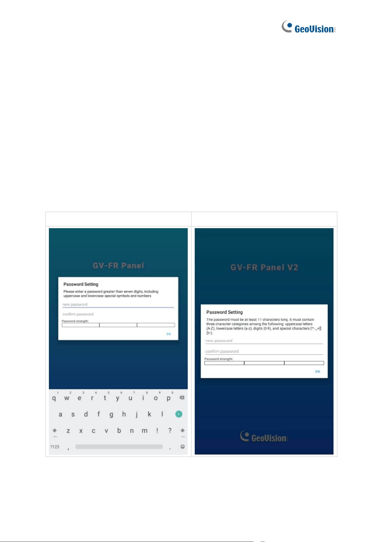
Upon first-time starting GV-FR Panel, users are prompted to set the login password for its
Administrator account. After setting the password, the live view of the GV-FR Panel’s built-in
camera appears.
GV-FR Panel V1:
GV-FR Panel V2:

27
After faces are registered in and recognized by the GV-FR Panel, a confirmation screen will
be displayed and overlaid on the live image.
There are several methods to register faces:
1. From the Web interface of GV-FR Panel. See how to find the IP address of GV-FR
Panel in 2.2 Looking up the IP Address, and then select Face Management > Face
Profiles on the Web interface. See 5.2 Face Management for more details on how to
create face profiles.
2. From the GV-ASManager access control system. See Chapter 4 User Management
on GV-ASManager and GV-FR Panel.
3. Using the GV-Face Manager utility. See 6.3 GV-Face Manager for Face Database
Management.
4. From the local GV-FR Panel. See the Local Enroll Mode option, 2.3 Local Settings.
5. Using GV-Face mobile app. See Chapter 5 Registering Face IDs to GV-AI FR Server /
GV-FR Panel in GV-Face Mobile App Installation Guide.
28
2.2 Looking up the IP Address
By default, GV-FR Panel is assigned an unused IP address by the DHCP server when it is
connected to a network. This IP address remains unchanged unless you unplug or
disconnect your reader from the network.
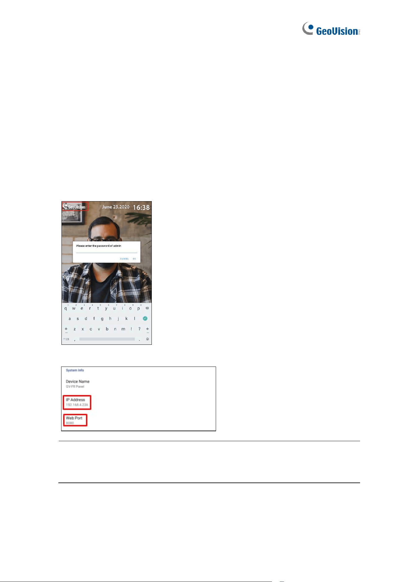
To check the IP address of your GV-FR Panel, follow the steps below.
1. On the main screen of GV-FR Panel, tap the GeoVision logo at the upper-left corner of
the touchscreen to enter the settings page. You’re prompted to type the password of its
Administrator account.
2. On the settings page, find the IP Address and Web Port of the GV-FR Panel.
.
Note: If the IP address appears as “0.0.0.0,” this means that the network has not been
established. Plug in the Ethernet cable to obtain the IP address. See 1.4 Connecting
GV-FR Panel.
29
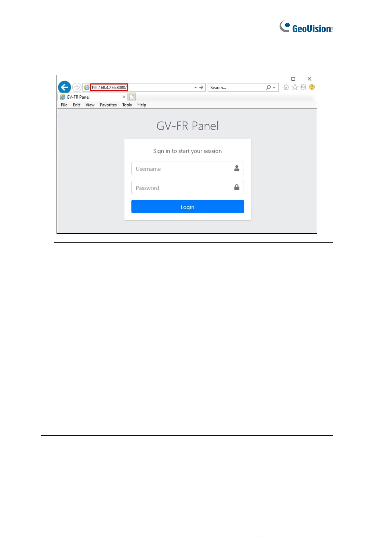
3. On a PC, open a Web browser and type the IP address and Web port of the GV-FR
Panel as exemplified below, e.g. 192.168.4.236:8080. The login page appears.
IMPORTANT: For accessing GV-FR Panel, it is required to add a colon and the port
number (default port: 8080) after the IP address, e.g. http://192.168.4.236:8080.
4. Type admin for the username and type the Administrator password of the GV-FR Panel
to log in.
For the detailed settings available on the Web interface of GV-FR Panel, see Chapter 5
Administrator Mode.
Note:
1. You can only change the IP address directly on GV-FR Panel. To assign a static IP
address to GV-FR Panel, use the local settings on the device. See 2.3 Local
Settings.
2. You can also use GV-IP Device Utility to search for the IP address of GV-FR Panel.
See 6.1 Upgrading System Firmware.
30
2.3 Local Settings
To access the GV-FR Panel’s local settings, tap the GeoVision logo at the upper-left corner
of the touchscreen panel, and type the login password that you’ve set. The following settings
page appears.
Note: If no logo is displayed at the upper-left corner of the touchscreen panel, tap the
empty upper-left corner, and the password prompt will appear as usual.
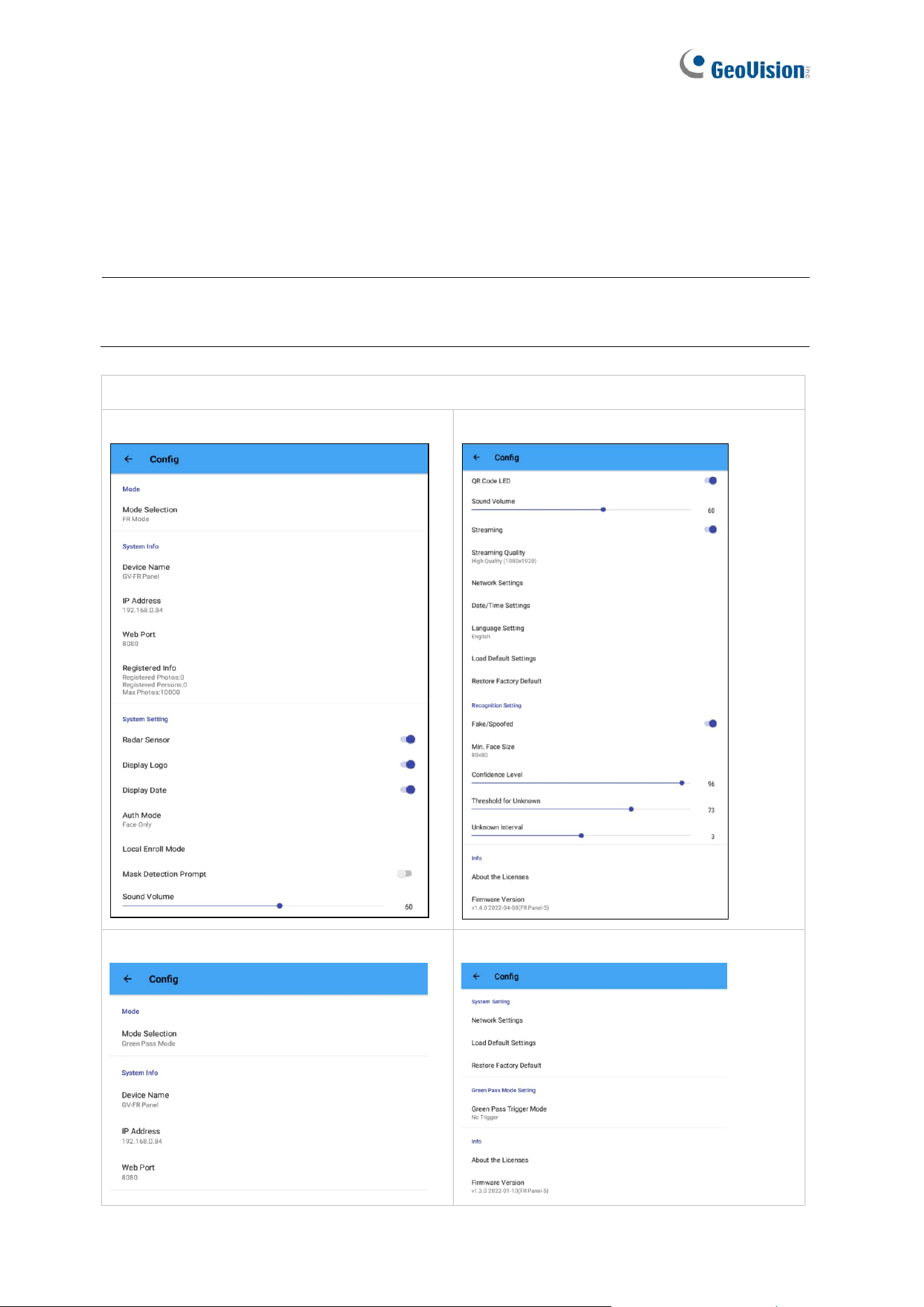
GV-FR Panel V1:
[FR Mode – Screenshot Page 1]
[FR Mode – Screenshot Page 2]
[Green Pass Mode – Screenshot Page 1]
[Green Pass Mode – Screenshot Page 2]
31
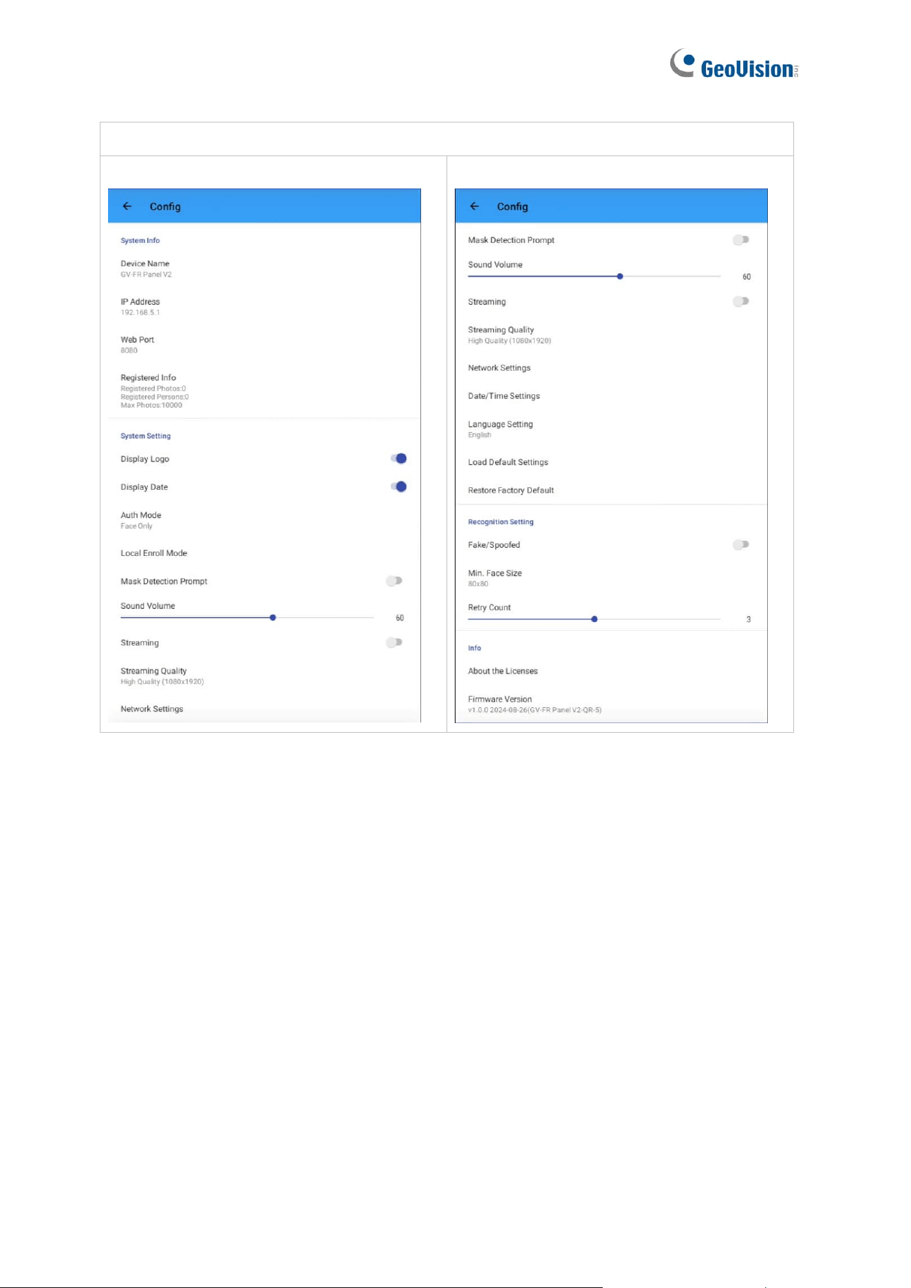
GV-FR Panel V2:
[Screenshot Page 1]
[Screenshot Page 2]

32
[Mode]
◼ Mode Selection: Only available for GV-FR Panel V1. Select FR Mode to grant access
by face recognition, or Green Pass Mode to grant access by scanning QR codes of the
EU Digital COVID Certificate.
Note: When using Green Pass Mode for the first time, it is required to connect GV-
FR Panel to the Internet for accessing the database of the EU Digital COVID
Certificate.
[System Info]
◼ Device Name: Displays the name of the device. “GV-FR Panel” and “GV-FR Panel V2”
are set as the default names for GV-FR Panel V1 and GV-FR Panel V2 respectively. To
change the device name from the device’s Web interface, see 5.1.1 System Settings.
◼ IP Address: Displays the IP address of the device. To change the IP address, see
Ethernet Setting below.
◼ Web Port: Displays the web port value of the device. The default value is 8080.
◼ Registered Info: Displays the number of users and face photos currently registered.
[System Settings]
◼ Radar Sensor: Only available for GV-FR Panel V1. Enable radar sensor for detecting
motion and automatically turning on the device’s white LED.
◼ Display Logo: Enabled by default. Displays the GeoVision logo or custom logo on the
touchscreen panel.
◼ Display Date: Enabled by default. Displays the time and date at the upper-right corner
of the touchscreen panel.
◼ Auth Mode: Select to authenticate and grant user access by Face Only mode, Card or
Face mode, or Card and Face mode. Face Only mode is enabled by default.
Note: The Card or Face mode also supports reading the QR code of visitor access
issued by GV-VMWeb. See Chapter 12 GV-VMWeb for Visitor Management in GV-
ASManager User’s Manual.
◼ Display NFC Detection Area: Only available for GV-FR Panel V1. The option is
available only when Card or Face is selected for Auth Mode. Disable to remove the NFC
detection area on the touchscreen panel.
33
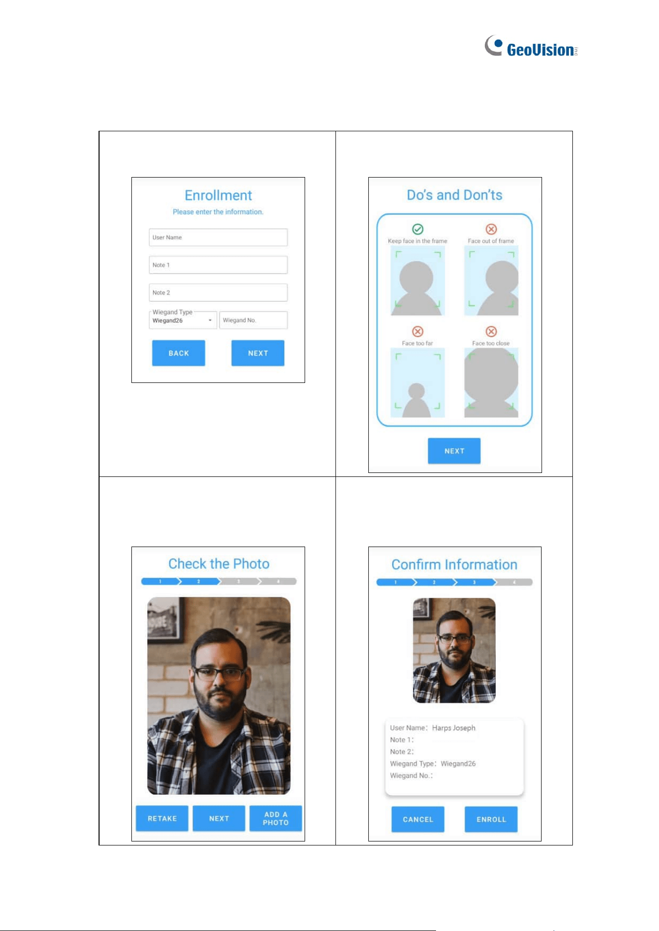
◼ Local Enroll Mode: Select to enroll faces directly on GV-FR Panel by following the
steps below.
1. Open Local Enroll Mode and fill in
the blank fields. Click Next.
2. Take a photo following the Do's and
Don'ts guidelines. Click Next.
3. Check the photo. Retake or add a
new photo if needed.
Click Next to proceed.
4. Confirm the information.
Click Enroll to complete the face
enrollment.

34
◼ Mask Detection Prompt: Click to enable Voice Alert for Mask and Display Mask Info.
⚫ Voice Alert for Mask: The audio clip “Please wear a face mask” is played when a
face without a mask is presented.
⚫ Display Mask Info: The notice “Please wear a face mask” is displayed when a
face without a mask is presented.
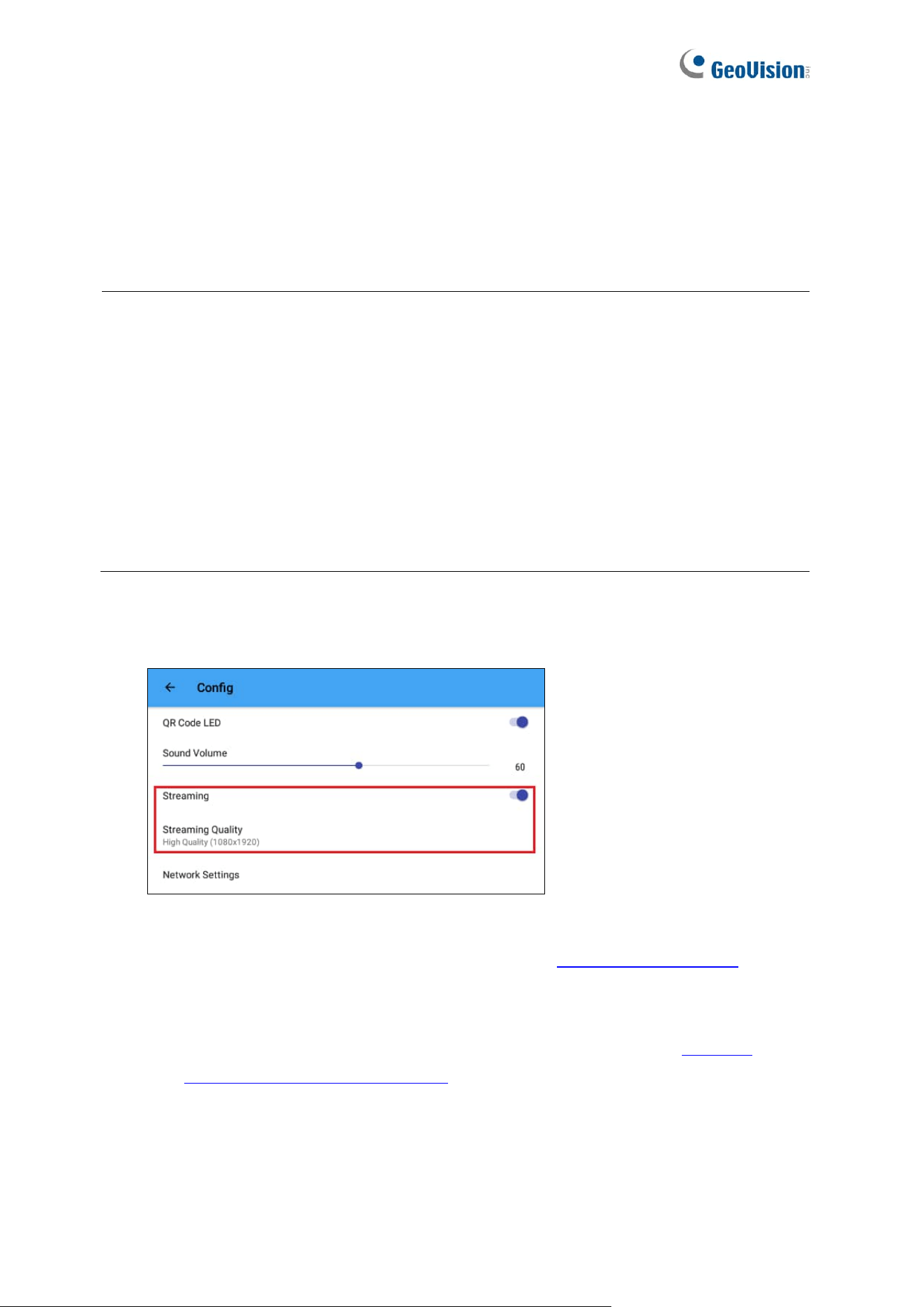
◼ QR Code LED: Only available for GV-FR Panel V1. Enabled by default, QR Code LED
turns on when detecting motion around. The option is available only when the Auth
Mode is set to Card or Face mode.
◼ Sound Volume: Adjusts the sound volume of the device. The default value is 60.
◼ Streaming: Click to allow connection to GV-VMS.
◼ Streaming Quality: Adjusts the live streaming resolution, including High Quality
(1080x1920), Medium Quality (480x720), and Low Quality (480x640). High Quality
(1080x1920) is selected as default.
◼ Network Settings: Enable DHCP or assign a static IP address.
◼ Date/Time Settings: Adjusts the date and time settings of the device.
⚫ Automatic date & time: Enabled by default. Uses network-provided time.
⚫ Time Zone: Select the time zone. Adjusts automatically according to network
changes.
⚫ Set date: Enabled when Automatic date & time is disabled. Set the date
manually.
⚫ Set time: Enabled when Automatic date & time is disabled. Set the time manually.
◼ Language Setting: Change the language of GV-FR Panel, from English as default, to
Bulgarian, Chinese Simplified, Chinese Traditional, Czech, English, French, German,
Indonesian, Italian, Japanese, Portuguese, Russian, Slovak, Spanish, Thai, and
Ukrainian.
◼ Load Default Settings: Loads the default settings of the device.
◼ Restore Factory Default: Loads the default settings of the device while clearing all
data registered.
IMPORTANT: The Restore Factory Default erases all your registered face profiles
and event logs from GV-FR Panel.

35
[Recognition Settings]
◼ Fake/Spoofed: Disabled as default. Enable to detect if the face is presented and
displayed on a digital device.
Note: In terms of anti-spoofing applications, liveness detection isn’t applicable to all
situations 100% of the time. For a higher level of security, the integration with GV-
ASManager for double-authentication, access card + face recognition, is strongly
suggested.
◼ Min. Face Size: Select the minimum face size in pixels for face recognition.
The face sizes are as follows:
GV-FR Panel V1: 80 x 80 (default), 100 x 100, 120 x 120, 140 x 140, and 160 x 160.
GV-FR Panel V2: 40 x 40 (default), 60 x 60, 80 x 80, 100 x 100, 120 x 120, 140 x 140,
and 160 x 160.
Refer to the technical notice for how to set the min. face size.
◼ Confidence Level: Only available for GV-FR Panel V1. Adjusts the confidence level for
face recognition. The higher the level, the more definitive and stricter the device is
toward distinguishing between similar faces. The default value is 80.
◼ Threshold for Unknown: Only available for GV-FR Panel V1. Adjusts the unknown
threshold for face recognition. Face recognition events below this confidence value are
recorded as unknown. The default value is 73.
◼ Unknown Interval: Only available for GV-FR Panel V1. The amount of time in seconds
before face recognition can be performed again on recognition targets that have been
identified as unknown.
◼ Retry Count: Only available for GV-FR Panel V2. The number of times facial
recognition can be repeated on recognition targets before they are identified as
unknown. The retry count ranges from 1 to 5. The default value is 3.
[Info]
◼ About the Licenses: Displays the detailed product license information.
◼ Firmware Version: Displays the firmware version of the GV-FR Panel.
36
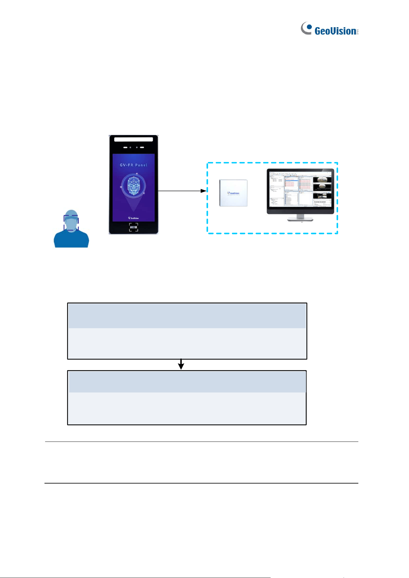
Chapter 3 Access Control Integration
This chapter explains how to set up the connections among GV-FR Panel, GV-AS Controller
and GV-ASManager software.
GV-FR Panel
GV-ASManager
Access Control Management
GV-AS Controller
+
Face
Recognition
LAN
Users need to complete all the configurations in Chapter 3 to connect GV-FR Panel to GV-
AS Controller and GV-ASManager software:
3.1.1 Adding GV-AS Controller
3.1.2 Setting GV-FR Panel to be a Door
Integrate with GV-ASManager
Add GV-AS Controller and GV-FR Panel to GV-ASManager
Once the three -- GV-FR Panel, GV-ASController and GV-
ASManager -- are connected, enroll user faces on GV-ASManager.
See Chapter 4.
User Management on GV-ASManager and GV-FR Panel
Note: Make sure your GV-AS Controller and GV-ASManager support connecting to
GV-FR Panel via network. See Firmware and Software Compatibility at the beginning of the
manual.
37
3.1 Setting up GV-ASManager
Integration with GV-ASManager allows you to utilize full access control functions. This
section covers the basic settings for connecting GV-Controller and GV-FR Panel to GV-
ASManager.
For more details on GV-ASManager functions, see GV-ASManager User’s Manual.
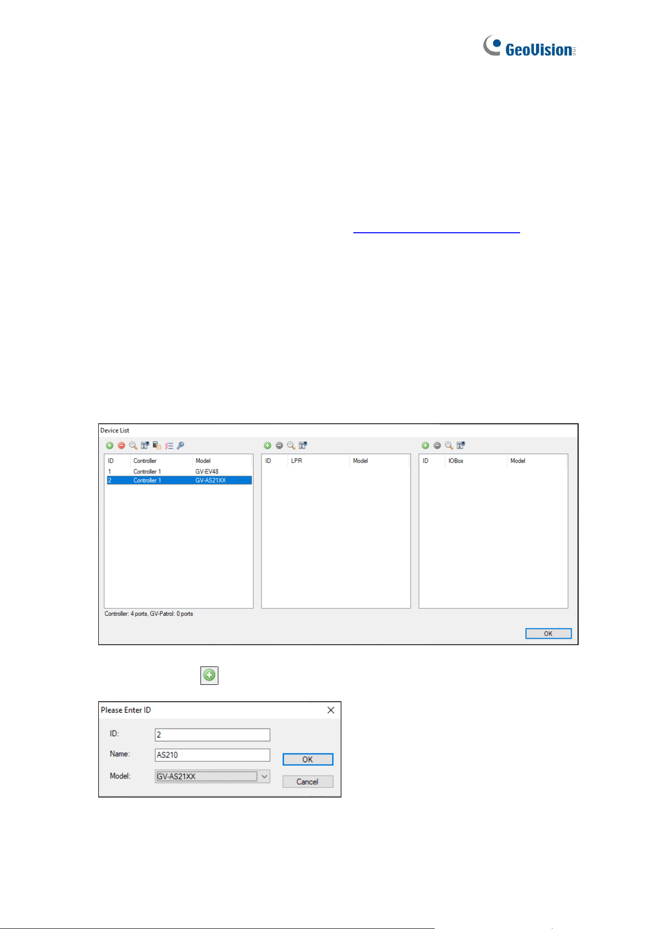
3.1.1 Adding GV-Controller
To connect GV-FR Panel and GV-AS Controller to GV-ASManager, you need to first connect
GV-AS Controller to GV-ASManager. To do so, follow the steps below.
1. On the menu bar of GV-ASManager, click Setup and select Devices. The Device List
dialog box appears.
2. Click the Add icon on the top left corner. This dialog box appears.
38
3. Specify the ID, Name and Model of the controller to be connected and click OK. This
dialog box appears.
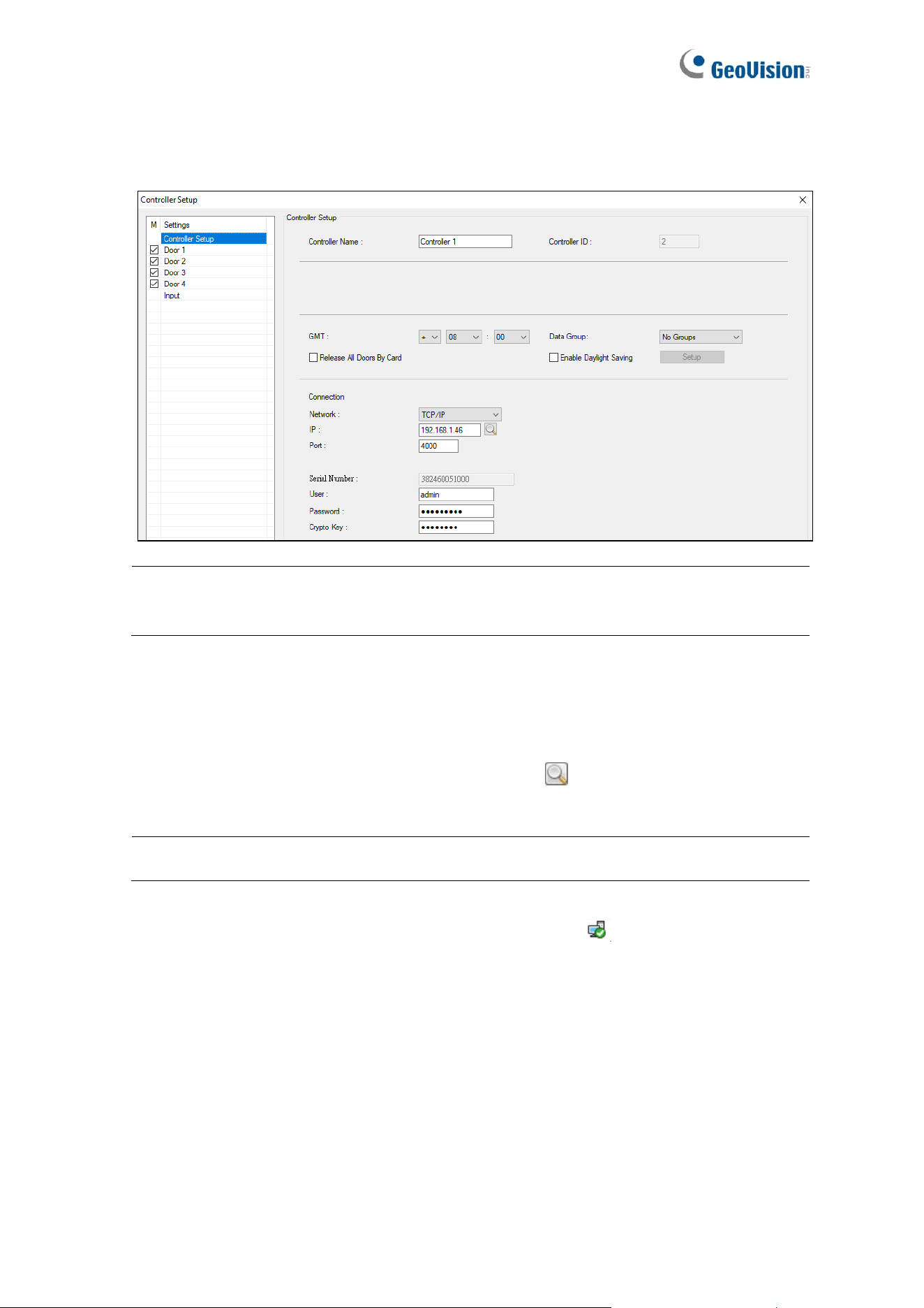
Note: The ID must match with that set up on the controller (Advance Setting > Function
Configuration).
4. In the Network dropdown list, select TCP/IP as the communication mode between the
controller and GV-ASManager.
5. Type the IP address, port number, login user, password and Crypto key (3DES code)
of the controller. You can also click the Search button to search for controllers within
the same LAN.
Note: By default, GV-AS Controller has a port value of 4000.
6. To check if connection settings are correct, click OK, and a icon should appear in the
Device View window indicating successful connection between the controller and GV-
ASManager.
39
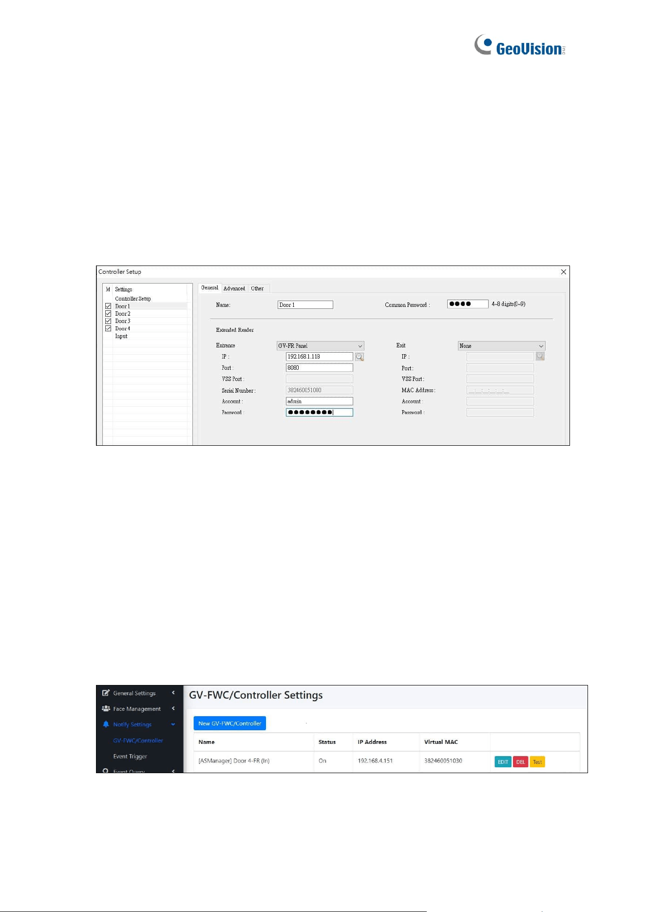
3.1.2 Setting GV-FR Panel to be a Door
Once GV-AS Controller has been connected to GV-ASManager, you then need to connect
GV-FR Panel to GV-AS Controller. To do so, follow the steps below.
1. On the menu bar of GV-ASManager, click Setup and select Devices.
2. Double-click the controller that GV-FR Panel to be connected to and select a Door. This
dialog box appears.
3. Select GV-FR Panel from the Entrance and/or Ext dropdown list, in accordance to your
installation site.
4. Type the IP address, Port number, Account ID and Password of the GV-FR Panel.
5. Click OK. The GV-FR Panel is connected to the controller and GV-ASManager is also
connected with GV-FR Panel.
To verify the connection on GV-FR Panel:
6. On the GV-FWC / Controller Setting page (Notify Settings > GV-FWC/Controller), you
should find an entry, for example, [ASManager] Door 4-FR (In), written back from GV-
ASManager to indicate which controller IP and which door is connected to.
40
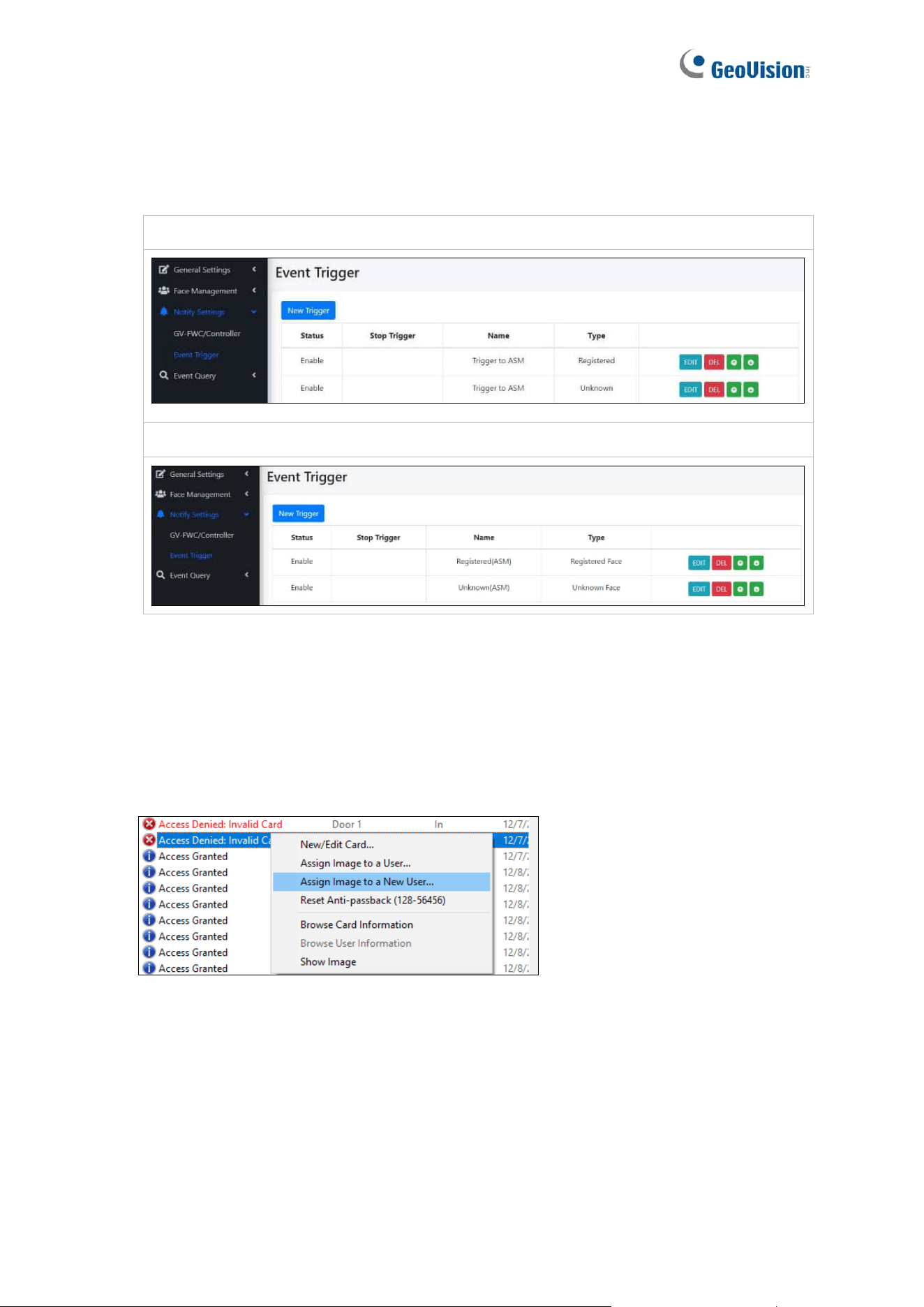
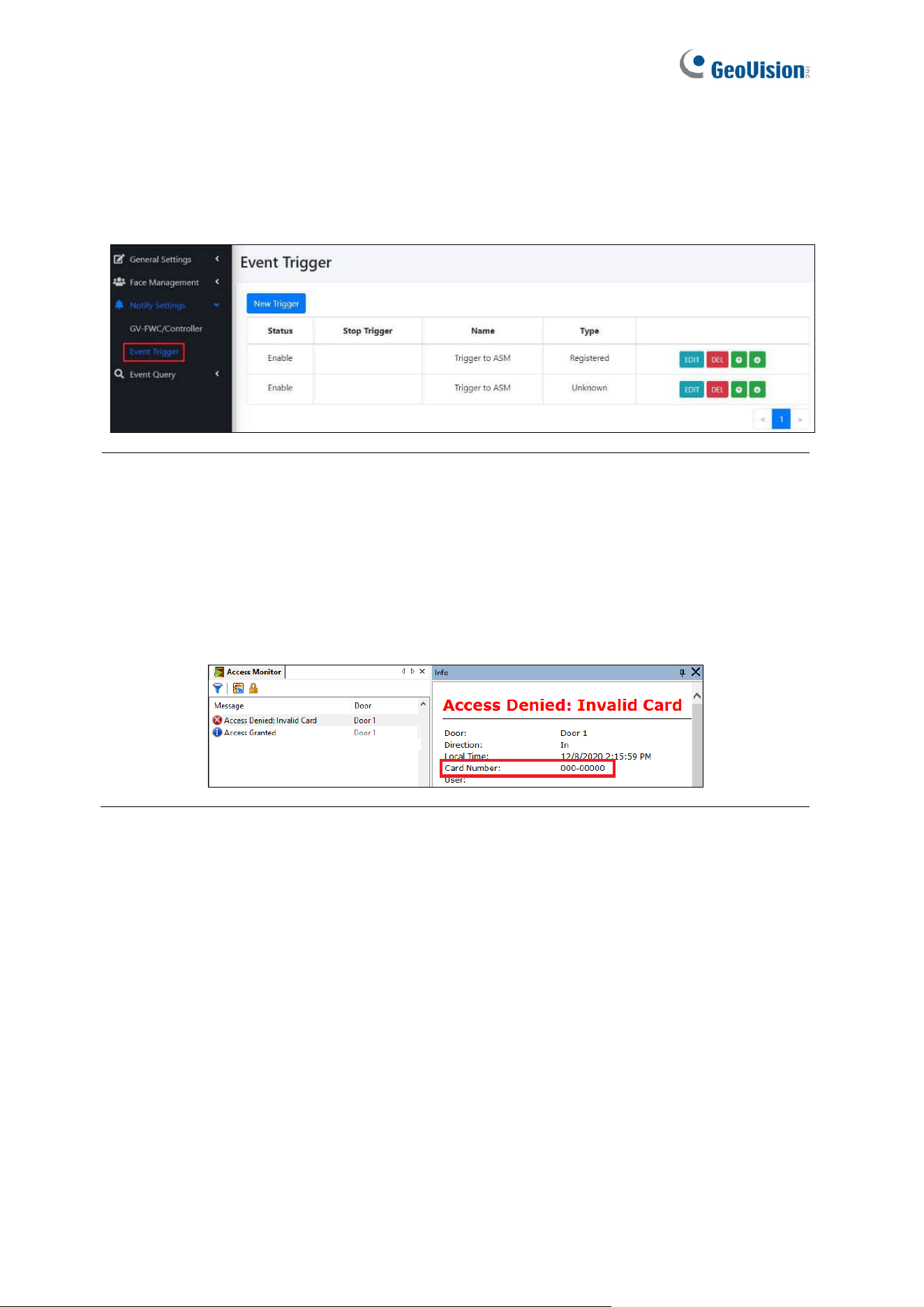
7. On the Event Trigger page (Notify Settings > Event Trigger), you should see two “ASM”
entries. No matter which condition, registered or unknown faces / cards, all will trigger
GV-FR Panel to send the access data to GV-ASManager.
GV-FR Panel V1:
GV-FR Panel V2:
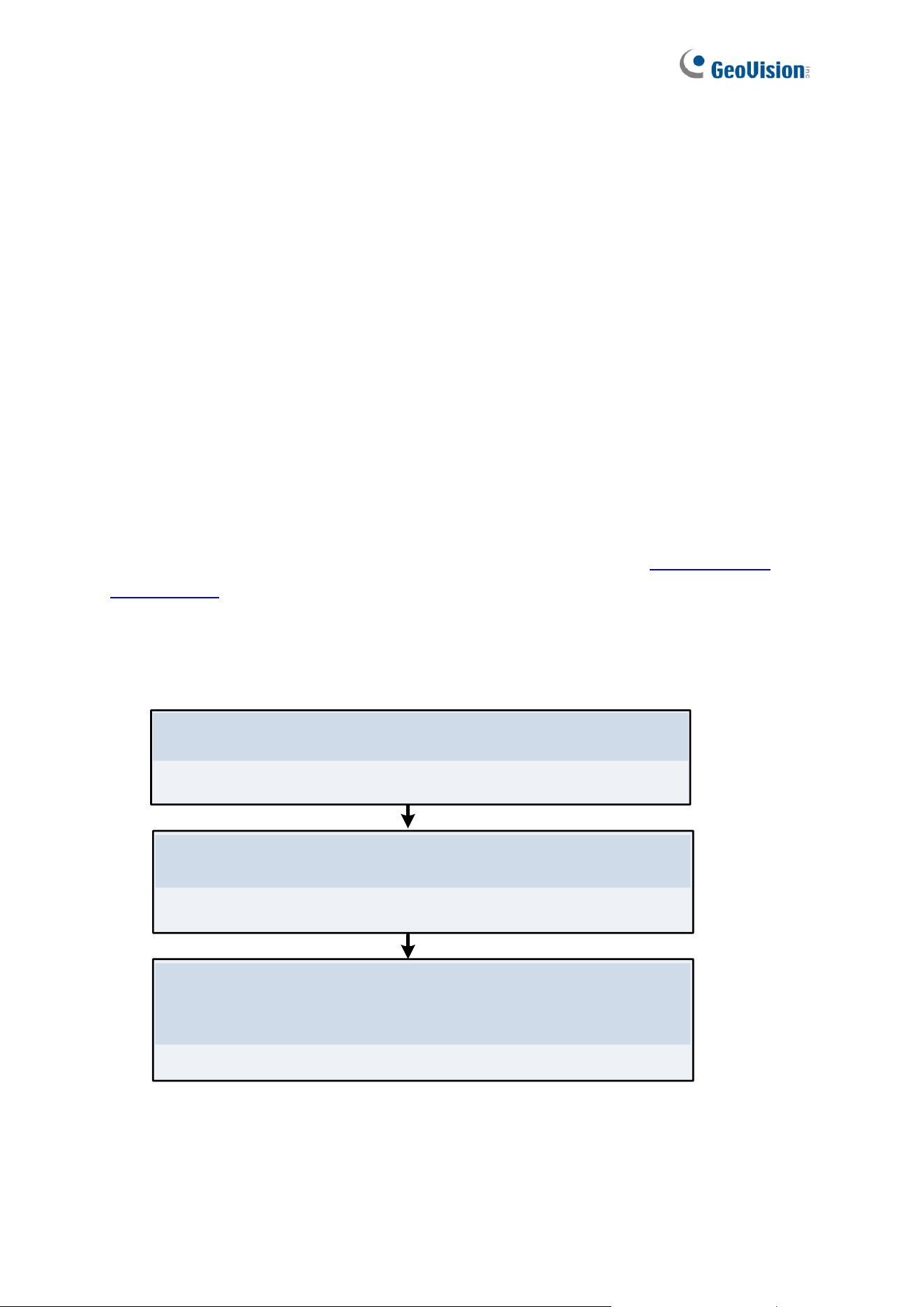
You can also do the following test to remotely enroll a face to GV-ASManager:
1. Show a face in front of the GV-FR Panel. The Access Denied Invalid Card message will
appear on GV-ASManager.
2. Right-click the message and select Assign Image to a New User to create a user
account in the GV-ASManager.
If the test fails, you may need to check the connection between GV-FR Panel and the
controller, see Appendix A.

41
Note:
1. By default, GV-FR Panel is set to face recognition only. To apply Card or Face mode
or Card + Face mode, go to the local settings of GV-FR Panel. See 2.3 Local Settings.
2. For details on other settings under the Door tab, see 4.2.2 Step 2: Configuring the
Doors or Elevator Floors in GV-ASManager User’s Manual.
42
Chapter 4 User Management on GV-
ASManager and GV-FR Panel
Once you have set up the connections among GV-FR Panel, GV-AS Controller and GV-
ASManager software, you can begin to create and manage users on GV-ASManager and
GV-FR Panel.
Setup Prerequisite:
Before enrolling face photos in GV-ASManager, you need to have completed the following
settings on GV-ASManager:
• Cards added
• Users added with Cards assigned
For details, see 4.3 Adding Cards and 4.6 Adding Users respectively in GV-ASManager
User’s Manual.
Follow the three steps below to enroll face photos in GV-ASManager and sync the user data
to GV-FR Panel:
4.3 Using GV-FR Panel
Use GV-FR Panel For Access Control
Authenticate access by three modes: Face Only, Card or Face
Card, Card + Face
4.1 Adding User Faces & Cards on GV-ASManager
Add User Faces and Cards on GV-ASManager
4.2 Uploading to GV-FR Panel
Upload User Data to GV-FR Panel
43
4.1 Adding User Faces & Cards on GV-ASManager
To enroll faces images for the Users in GV-ASManager, follow the steps below.
1. On the menu bar of GV-ASManager, click Personnel > Users. The User List window
appears.
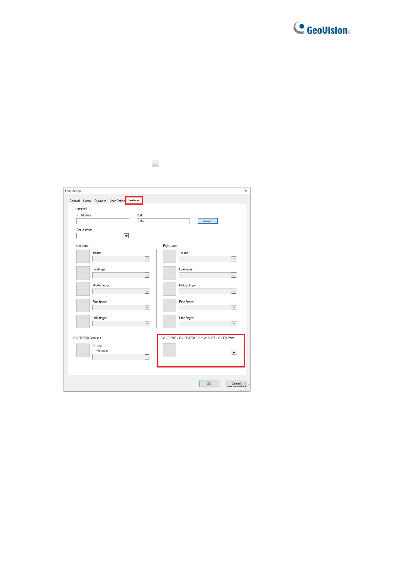
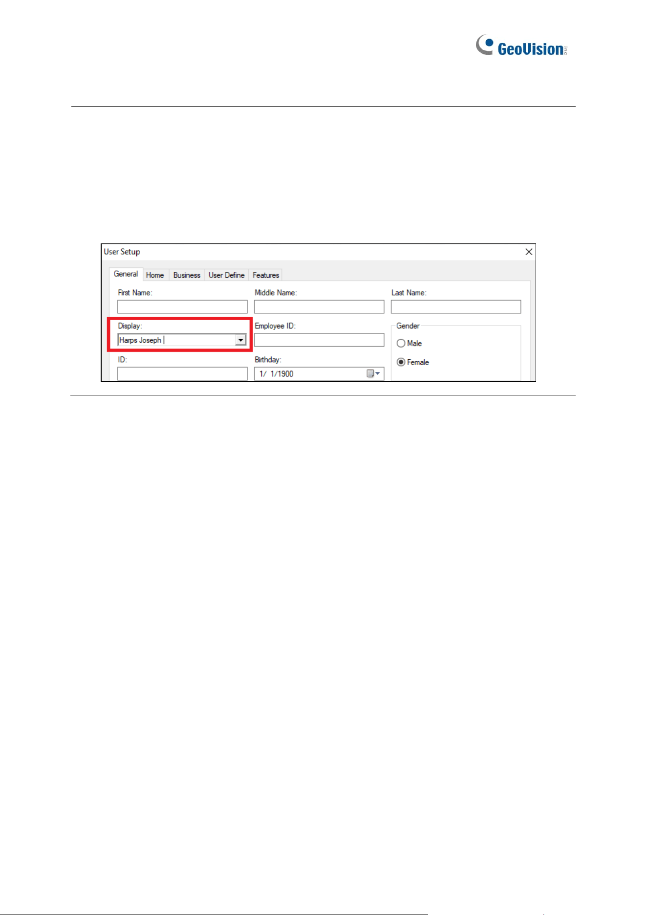
2. Double-click a User from the User List. The User Setup dialog box appears.
3. Select the Features tab.
4. Click on the image column under GV-VD8700 / GV-FD8700-FR / GV-AI FR / GV-FR
Panel.
44
5. In the Image Selection window, use one of the following three options to add a face
photo for the User. Up to 3 photos for one User can be added.
A. Click Webcam Capture to take a face photo with a connected webcam camera.
B. Click Add to browse for a face photo from the PC.
C. Click Add from Logs to use a snapshot captured within the GV-ASManager’s
logs.
6. Optionally crop the face photo if needed. Click OK.
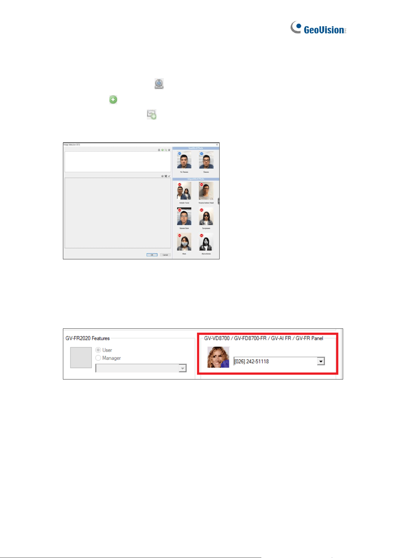
7. After the photo has been added, select an access card number for the User within the
dropdown list next to the face photo. The paired access card number can be used in
Card or Face mode or Card + Face mode when applicable.
8. Click OK to apply the settings.
The face photo has now been added to the User and paired to the access card number
selected for face-recognition-based access control.
45
Note:
1. For FR-based access control to work, the same Users, along with their face photos and
access card numbers, must also be uploaded to GV-FR Panel, see the following section
4.2 Uploading to GV-FR Panel.
2. When uploading Users to GV-FR Panel, their Display Names, set up in the User Setup
dialog box, will be the names of faces in the GV-FR Panel database.
46
4.2 Uploading to GV-FR Panel
To upload Users to GV-FR Panel, along with their face photos and access card numbers,
follow the steps below.
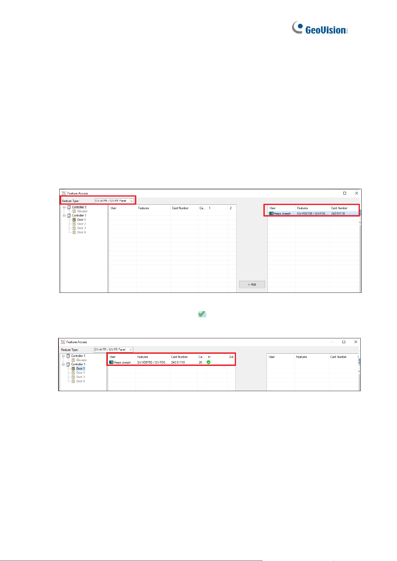
1. On the menu bar of GV-ASManager, click Setup > Feature Access. The Feature Access
dialog box appears.
2. Select GV-AI FR / GV-FR Panel from the Feature Type. From the left column, select the
corresponding Door to which the GV-FR Panel is connected.
3. Select the desired User from the right column. The Add button becomes available.
4. Click the Add button to add the User to the selected Door. The resulting window after
adding may look like this, with a green tick indicating that the User has been
successfully uploaded to the GV-FR Panel.
47
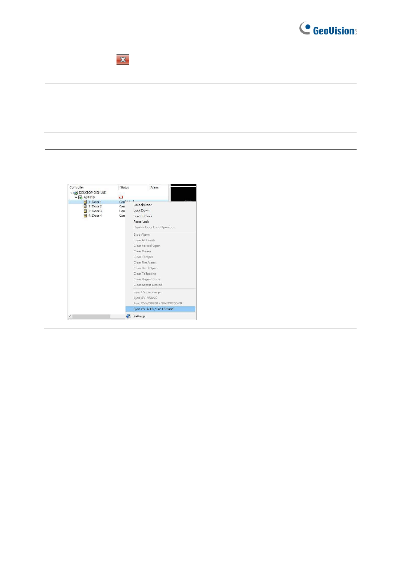
5. Click the ‘x’ icon to close the Feature Access window.
Note:
1. Each GV-FR Panel can store up to 10,000 face photos.
2. The face photos uploaded will be saved in both GV-FR Panel and GV-ASManager.
IMPORTANT: The Sync GV-AI FR / GV-FR Panel function on GV-ASManager replaces
the current face database of GV-FR Panel, erasing all event logs on it.

48
4.3 Using GV-FR Panel
After uploading the user data from GV-ASManager to GV-FR Panel, you can start managing
its access control by one of the following three authentication modes: Face Only, Card or
Face and Card + Face.
4.3.1 Face Only Mode
In the default mode of face recognition only, when the presented face matches any
registered user faces, a confirmation screen will appear on the GV-FR Panel with an access
signal being passed to the controller.
On GV-ASManager, a message “Access Granted” will be displayed. When you click the
message, its associated photo enrolled and the live image captured onsite will be available.

49
4.3.2 Card or Face Mode
The Card or Face mode allows users to gain access with either a paired card or face
recognition. To manage access by face recognition or card swipe, make sure Card or Face
is selected as the GV-FR Panel’s authentication mode, see 2.3 Local Settings
4.3.3 Card + Face Mode
The Card + Face mode only allows users to gain access when both the user’s card and face
have been authenticated. To manage access by card swipe and face recognition, make sure
Card and Face is selected as the GV-FR Panel’s authentication mode, see 2.3 Local
Settings.
In order to be granted access, the personnel accessing must first swipe a paired card and
then perform face recognition on the GV-FR Panel. Once both have been authenticated, a
confirmation screen will appear with an access signal being passed to the controller. If the
face presented cannot be recognized by the GV-FR Panel, within 7 seconds, the access will
be denied.
50
Chapter 5 Administrator Mode
The Administrator can access and configure all the settings of the GV-FR Panel over the
network. The configuration categories include: General Settings, Face Management,
Notify Settings and Event Query.
Corresponding Section for Configuration Menu
Find the topic of interest by referring to the sections below.
5.1 General Settings
5.1.1 System Settings
5.1.2 Account & Authority
5.1.3 Recognition Settings
5.1.4 Relay Settings
5.2 Face Management
5.2.1 Face Profiles
5.3 Notify Settings
5.3.1 GV-FWC/Controller
5.3.2 Event Trigger
5.4 Event Query
5.4.1 Detail Log
5.4.2 Exported Files
51
5.1 General Settings
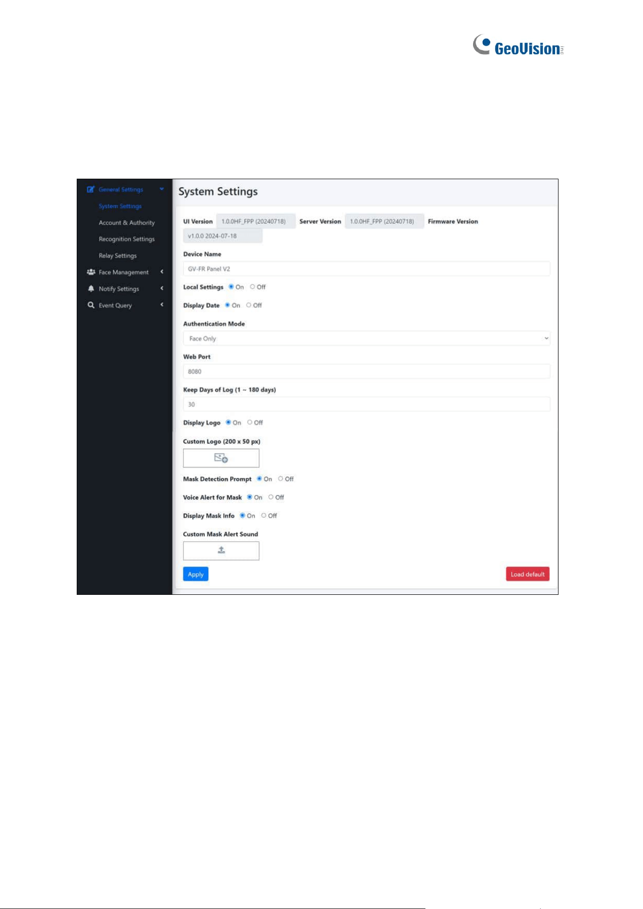
5.1.1 System Settings
◼ Device Name: Type a desired name for the GV-FR Panel. “GV-FR Panel” and “GV-FR
Panel V2” are set as the default names for GV-FR Panel V1 and GV-FR Panel V2
respectively.
◼ Local Settings: Enabled by default. Select On to enable the accessibility of the local
settings. For details, see 2.3 Local Settings.
◼ Radar Sensor: Only available for GV-FR Panel V1. Select Auto to enable radar sensor
for detecting motion and automatically turning on the device’s white LED.
◼ QR Code LED: Only available for GV-FR Panel V1. Enabled by default. Select Auto for
the QR Code LED to turn on when detecting motion around.
◼ Display Date: Enabled by default. Select On for the time and date to be displayed at
the upper-right corner of the touchscreen panel.

52
◼ Authentication Mode: Select to authenticate and grant user access by three modes:
Face Only, Card or Face, Card and Face. Face Only mode is selected as default.
◼ Web Port: Optionally modify the default web port value of 8080.
◼ Keep Days of Log (1 ~ 180 days): Define the number of days the log data are kept for.
The default value is 30.
◼ Display Logo: Enabled by default. Select On for the GeoVision logo or custom logo to
be displayed on the touchscreen panel.
◼ Custom Logo (200 x 50 px): Optionally add a desired logo, with a pixel size of 200 x 50,
to be displayed at the upper-left corner of the GV-FR Panel, in place of the GeoVision
logo.
◼ Mask Detection Prompt: Select On to enable the following three options:
⚫ Voice Alert for Mask: Select On for the audio clip “Please wear a face mask” to
play when a face without a mask is presented.
⚫ Display Mask Info: Select On for the notice “Please wear a face mask” to appear
when a face without a mask is presented.
⚫ Custom Mask Alert Sound: Optionally add a desired alert sound. Note that only
MP3 files within 100 KB are applicable.
◼ Load Default: Loads the default settings of the device.
⚫ Restore to factory settings: Loads the default settings of the device while
clearing all data registered.
⚫ Restore Default Settings: Loads the default settings of the device while keeping
all data registered (i.e. login and user data).
IMPORTANT: The Restore to factory settings option under Load Default erases all
your registered face profiles and event logs from GV-FR Panel.
53
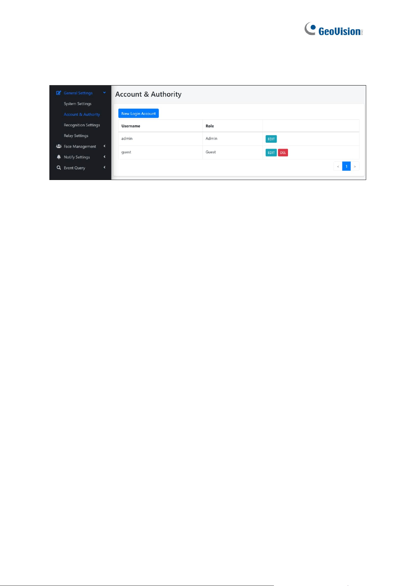
5.1.2 Account & Authority
On the Account & Authority page, users can create additional Administrator and Guest
accounts for accessing the GV-FR Panel.
54
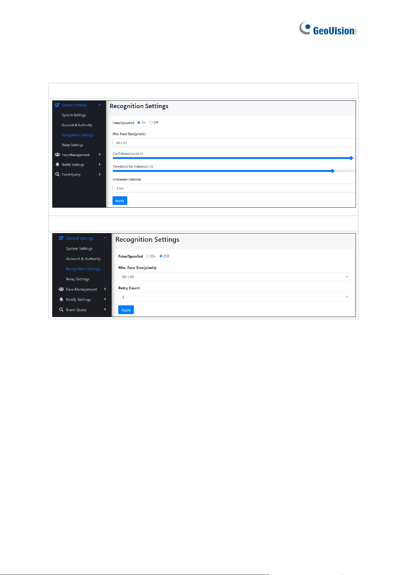
5.1.3 Recognition Settings
GV-FR Panel V1:
GV-FR Panel V2:
◼ Fake / Spoofed: Select On to detect if the face is presented and displayed on a digital
device.
◼ Min. Face Size: Select the minimum face size in pixels for face recognition.
The face sizes are as follows:
GV-FR Panel V1: 80 x 80 (default), 100 x 100, 120 x 120, 140 x 140, and 160 x 160.
GV-FR Panel V2: 40 x 40 (default), 60 x 60, 80 x 80, 100 x 100, 120 x 120, 140 x 140,
and 160 x 160.
◼ Confidence Level: Only available for GV-FR Panel V1. Adjusts the confidence level for
face recognition. The higher the level, the more definitive and stricter the device is
toward distinguishing between similar faces. The default value is 80.
◼ Threshold for Unknown: Only available for GV-FR Panel V1. Adjusts the unknown
threshold for face recognition. Face recognition events below this confidence value are
recorded as unknown. The default value is 73.

55
◼ Unknown Interval: Only available for GV-FR Panel V1. The amount of time in seconds
before face recognition can be performed again on recognition targets that have been
identified as unknown.
◼ Retry Count: Only available for GV-FR Panel V2. The number of times facial
recognition can be repeated on recognition targets before they are identified as
unknown. The retry count ranges from 1 to 5. The default value is 3.
56
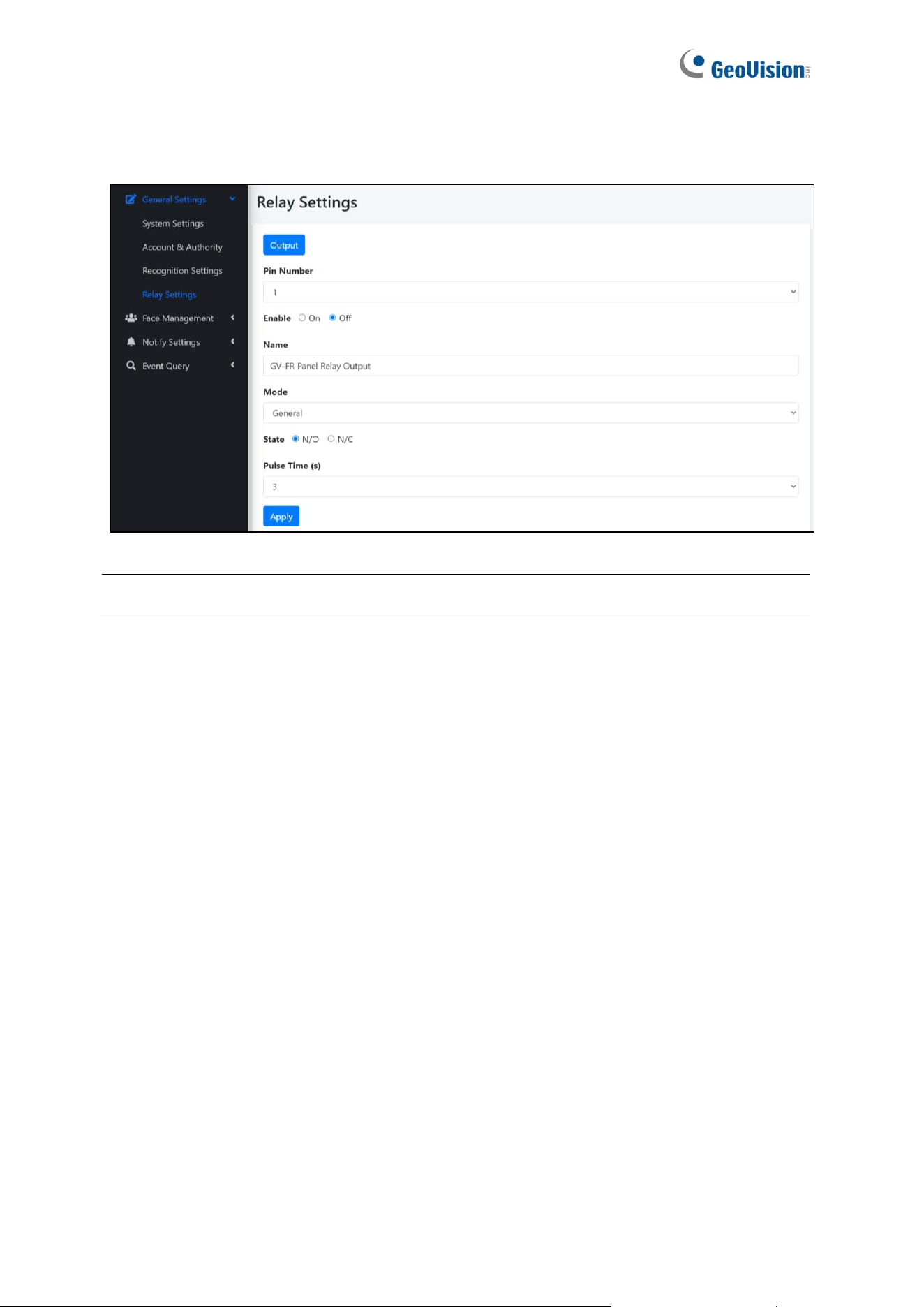
5.1.4 Relay Settings
You can set up an output device to be triggered as soon as registered faces are recognized.
Note: Make sure an output device is connected to the GV-FR Panel.
◼ Output: Force triggers the connected output.
◼ Pin Number: The GV-FR Panel only supports one output pin and device.
◼ Enable: Select On to enable the output to be triggered.
◼ Name: Type a desired named for the output device. GV-FR Panel IO Output and GV-
FR Panel Relay Output are set as the default names for GV-FR Panel V1 and GV-FR
Panel V2 respectively.
◼ Mode: Select an output trigger mode from the following options:
• General: Triggers the output only once. Selected as default.
• Toggle: Always triggers the output.
• Pulse: Triggers the output for the amount of time specified under Pulse Time (s).
◼ State: Defines its non-triggered state as normally open or normally closed. N/O
(normally open) is selected as default.
◼ Pulse Time (s): Specify the amount of time (in seconds) that the output is triggered
when Pulse mode is selected. The default value is 3.
To trigger the configured output device upon face / card recognition events, select Notify
Settings > Event Trigger > New Trigger and select Relay Output under Trigger Output.
See 5.3.2 Event Trigger.
57
5.2 Face Management
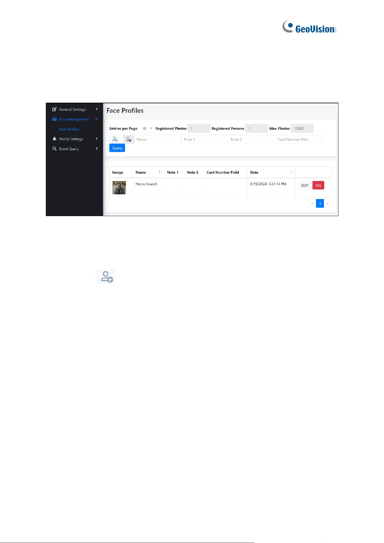
5.2.1 Face Profiles
On the Face Profiles page, users can enroll face photos used for access control by the GV-
FR Panel. Users can also search for previously created face profiles by applying the desired
search criteria and clicking Query.
◼ New Face : Create face profiles. Continue reading this chapter for more details.
◼ Entries per Page: Select the number of entries shown per page, including 10 and 20.
The default value is 10.
◼ Query:
⚫ Search Criteria: Type Name, Note 1, Note 2 or Card Number Field in their
respective fields. The search results are displayed based on the criteria set.
58
Note:
1. For having consistent user data between GV-FR Panel and GV-ASManager, you
need to create user accounts and enroll face photos in GV-ASManager and then
sync the data back to GV-FR Panel.
⚫ For integration with GeoVision controllers and software, see Chapter 3 Access
Control Integration.
2. You can also use GV-Face Manager utility to create face profiles. See 6.3 GV-Face
Manager for Face Database Management.
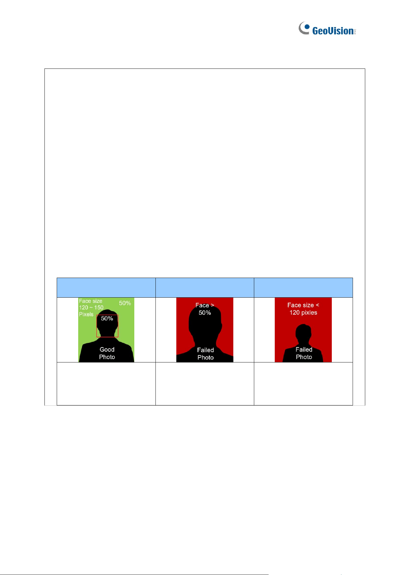
3. Note the following requirements for the face enrollment:
⚫ Each photo must consist of only one face.
⚫ Size of the face within the photo should be within 120 ~ 150 pixels.
⚫ The file size of the photo cannot exceed 50 KB.
⚫ Only JPEG format is supported.
⚫ Make sure the face of the person does not occupy more than 50% of the
image.
Ideal
Failed to enroll – 1
Failed to enroll – 2
The face occupies 50% of
the image. The size of the
person’s face is between
120 ~150 pixels.
The face occupies more
than 50% of the image.
The size of the person’s
face is less than 120
pixels.
59
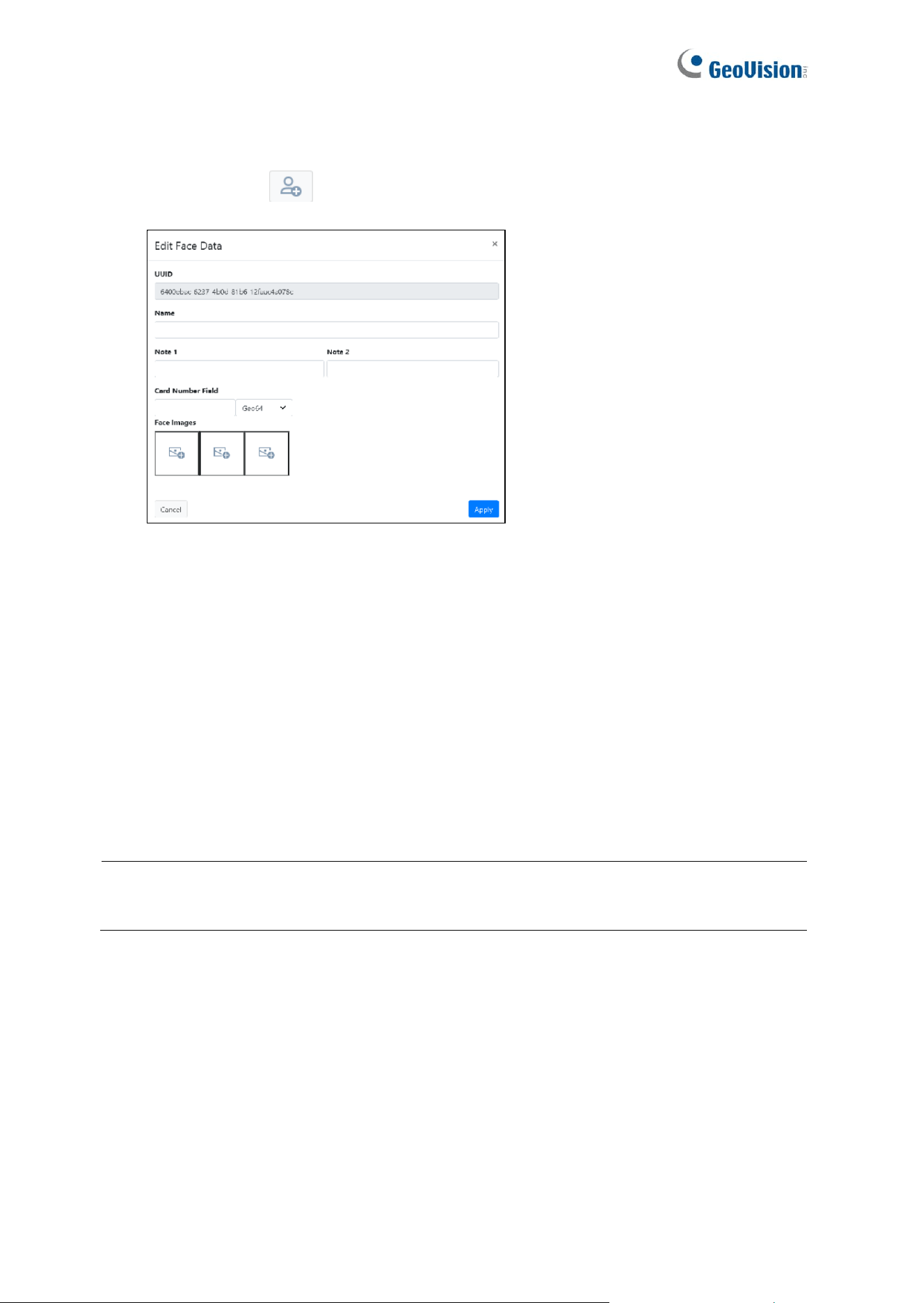
To create a face profile, follow the steps below.
1. Click New Face . This window appears.
2. Type a desired name for the face profile under Name.
3. Optionally type notes for the face profile under Note 1 and Note 2.
4. Type the number of the access card to be assigned to the face profile under Card
Number Field. Select the corresponding card format from the dropdown list, including
Wiegand26, HID32, Geo34, HID35, HID37, HID40, and Geo64. Geo64 is selected as
default.
5. Click the icon under Face Images to browse for and add up to 3 face photos for the face
profile.
6. Click Apply. The face profile is created.
IMPORTANT: When you delete a created face profile, its related event logs will also be
erased.
60
5.3 Notify Settings
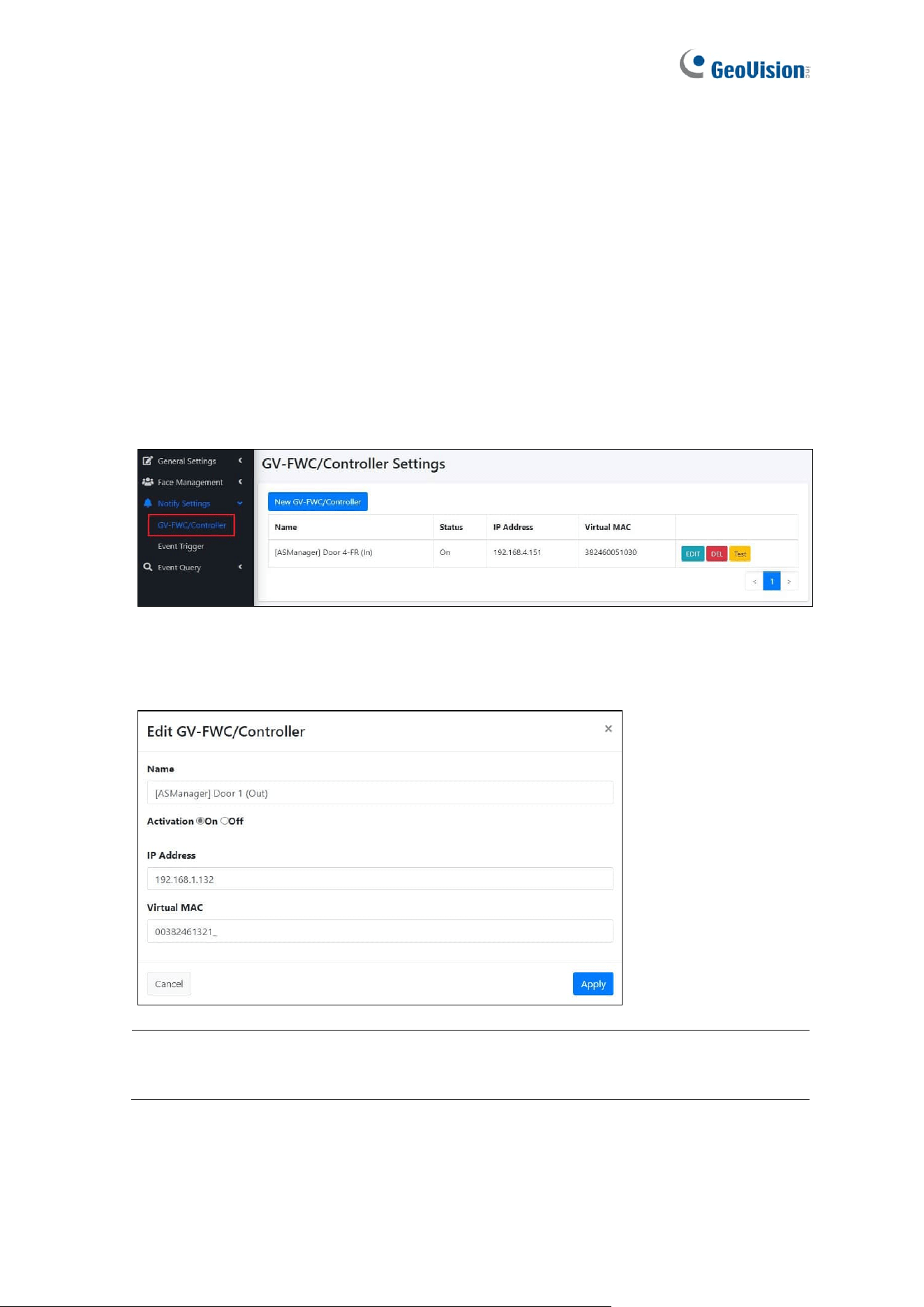
5.3.1 GV-FWC/Controller
The GV-FWC/Controller page allows users to check the connection information of the
connected GV-AS Controller, or add a GV-FWC for third-party integration. To add a GV-FWC,
see details in 7.2 Via GV-FWC Converter.
1. To configure a GV-FWC/Controller, follow the steps below. On the Web interface of GV-
FR Panel, select Notify Settings > GV-FWC/Controller.
2. Click EDIT, which is next to the GV-FWC/Controller entry, to change the device name
and IP address, and enable/disable connection if necessary.
Note: The Web interface displays “Virtual MAC” for GV-FR Panel V1 and “Serial
Number” for GV-FR Panel V2.
3. Click Apply at the bottom right corner of the page for the changes to apply.
61
5.3.2 Event Trigger
The Event Trigger page allows users to set up various trigger actions upon face / card
recognition events.
Note: Once GV-ASManager is connected to GV-FR Panel successfully, you will see two
entries of “Trigger to ASM” automatically created on this page. No matter which condition,
registered or unknown faces / cards, the access data will be sent to the GV-ASManager.
For example, if there is a corresponding user account for the face / card presented, the
message “Access Granted” will appear on the GV-ASManager. If the face / card presented
is not registered on the GV-ASManager, the message “Access Denied: Invalid Card” will be
displayed, with an empty card number “000-00000.”
To set up or configure a trigger action, follow the steps below.
1. On the Web interface of GV-FR Panel, select Notify Settings > Event Trigger.
62
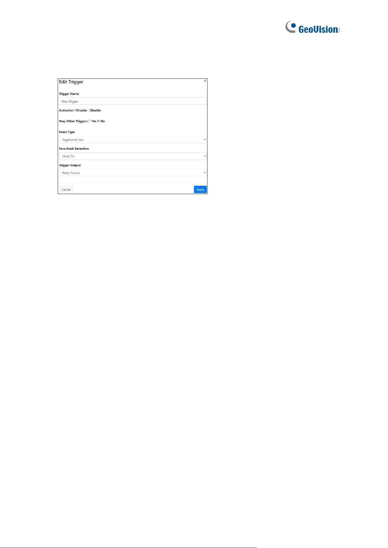
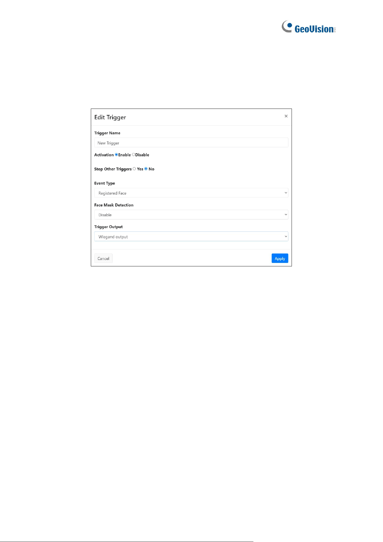
2. To set up a new trigger action, click New Trigger. To configure a trigger action, click EDIT.
This dialog box appears.
3. Name the trigger under Trigger Name.
4. Select Enable next to Activation.
5. Select Yes for Stop Other Triggers to stop other previously created triggers from being
triggered at the same time.
6. Under Event Type, select an event to activate a trigger action.
◼ Unknown Face: Triggers an action when unknown faces / cards are detected.
◼ Registered Face: Triggers an action when registered faces / cards from the
database are recognized. Selected as default.
7. Under Face Mask Detection, select whether wearing a face mask or not will also trigger
an action.
8. Under Trigger Output, select a trigger action.
◼ None: No action is triggered.
◼ GV-FWC/Controller: When the trigger conditions are met, the captured facial image
and card number are transmitted to the access control software GV-ASManager via
GV-Controller.
◼ GV-Face App: When the trigger conditions are met, the captured facial image and
card number are transmitted to the GV-Face mobile app.
◼ Relay Output: When the trigger conditions are met, the connected output device,
e.g. an alarm, is activated. Selected as default. To set up an output device, see 5.1.4
Relay Settings.
◼ Wiegand Output: When the trigger conditions are met, the card number is
transmitted to a third-party access control system. See Chapter 7 Third-Party
Controller Integration.
9. Click Apply at the bottom right corner of the page for the changes to apply.
63
5.4 Event Query
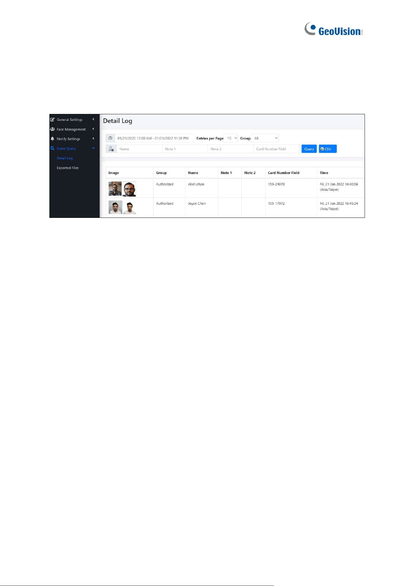
5.4.1 Detail Log
The Event Query allows users to search for events during a specified time. When accessing
Detail Log, apply the desired search criteria and click Query.
◼ Entries per Page: Select the number of entries shown per page, including 10, 20, 30,
40, and 50. The default value is 10.
◼ Query:
⚫ Time: Set a start time and end time to filter for events that occur within this time
range.
⚫ Group: Select a group to filter for a specific group of people, including All,
Unknown, and Authorized. All is selected as default.
⚫ Other Search Criteria: Type Name, Note 1, Note 2 or Card Number Field in their
respective fields.
The search results are displayed based on the criteria set, with the data explained below.
◼ Image (Live/Enrolled): Displays the face snapshot captured upon face / card
recognition, along with the face image already enrolled for the Face Profile recognized.
◼ Group / Name / Note 1 / Note 2 / Card Number Field: Displays the group, name, note
1, note 2 and the card number of the Face Profile recognized.
◼ Time: Displays the time of the recognition event.
64
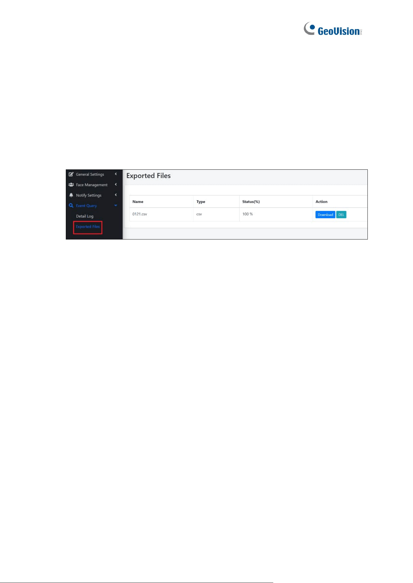
5.4.2 Exported Files
On the Exported Files page, users can export the event logs found in the Detail Log page.
To do so, follow the steps below.
1. Click the CSV button at the upper right of the Detail Log page, which appears after each
query.
2. Click Event Query > Exported Files.
3. Click Download.

65
Chapter 6 Advanced Applications
This chapter introduces more advanced applications.
6.1 Upgrading System Firmware
GeoVision periodically updates the latest firmware to the company website. You can update
GV-FR Panel’s firmware through GV-IP Device Utility (V8.9.3 or later) from the website.
Important Notes Before You Start
Before you start updating the firmware, read these important notes:
1. While the firmware is being updated, the power supply must not be interrupted.
2. If you use GV-IP Device Utility for firmware upgrade, the computer used to upgrade
firmware must be within the same network as the GV-FR Panel.
3. If firmware upgrade fails, you will need to restore the GV-FR Panel to its default settings.
For details, see 6.2 Restoring to Factory Default Settings.
WARNING: The interruption of power supply during updating causes not only update
failures but also damages to your GV-FR Panel. In this case, contact your sales
representative and send your device back to GeoVision for repair.
66
Using the GV-IP Device Utility
GV-IP Device Utility provides a direct way to upgrade the firmware to multiple GV-FR Panels.
Note: The computer used to upgrade firmware must be within the same network as the
GV-FR Panel.
1. Once downloaded, select GV IP Device Utility, and follow the onscreen instructions to
install the program.
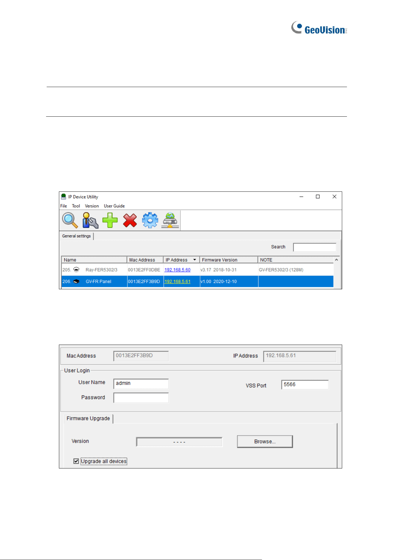
2. Double-click the GV IP Device Utility icon created on your desktop. This dialog box
appears.
3. Click the Search button to locate available devices on the LAN, or click the New button
and assign an IP address to locate a GV-FR Panel on the network.
4. Double-click on the IP address of the GV-FR Panel. This dialog box appears.
5. Click the Browse button to locate the firmware files (.img) saved at your local computer.
6. If you would like to upgrade all the GV-FR Panels in the list, check Upgrade all devices.
7. Type the Password of the GV-FR Panel, and click Upgrade to start the upgrade.

67
6.2 Restoring to Factory Default Settings
If for any reason the device is not responding properly, you can restore it to its factory default
settings through the Web interface.
1. Click General Settings > System Settings.
2. Click Load Default.
68
6.3 GV-Face Manager for Face Database Management
GV-Face Manager is a useful utility that allows you to manage the face database of GV-FR
Panel. It features the following functions for GV-FR Panel:
⚫ Creating face profiles: See 2.2 Adding / Editing Face IDs in GV-Face Manager User’s
Guide.
⚫ Synchronizing face databases among more than one GV-FR Panel: See 2.5
Synchronizing Databases in GV-Face Manager User’s Guide.
⚫ Importing and exporting a face database: See 3.3 Face Database Backup in GV-
Face Manager User’s Guide.
⚫ Batch enrolling faces: See 2.4 Batch Enrolling Faces and Access Cards in GV-Face
Manager User’s Guide.
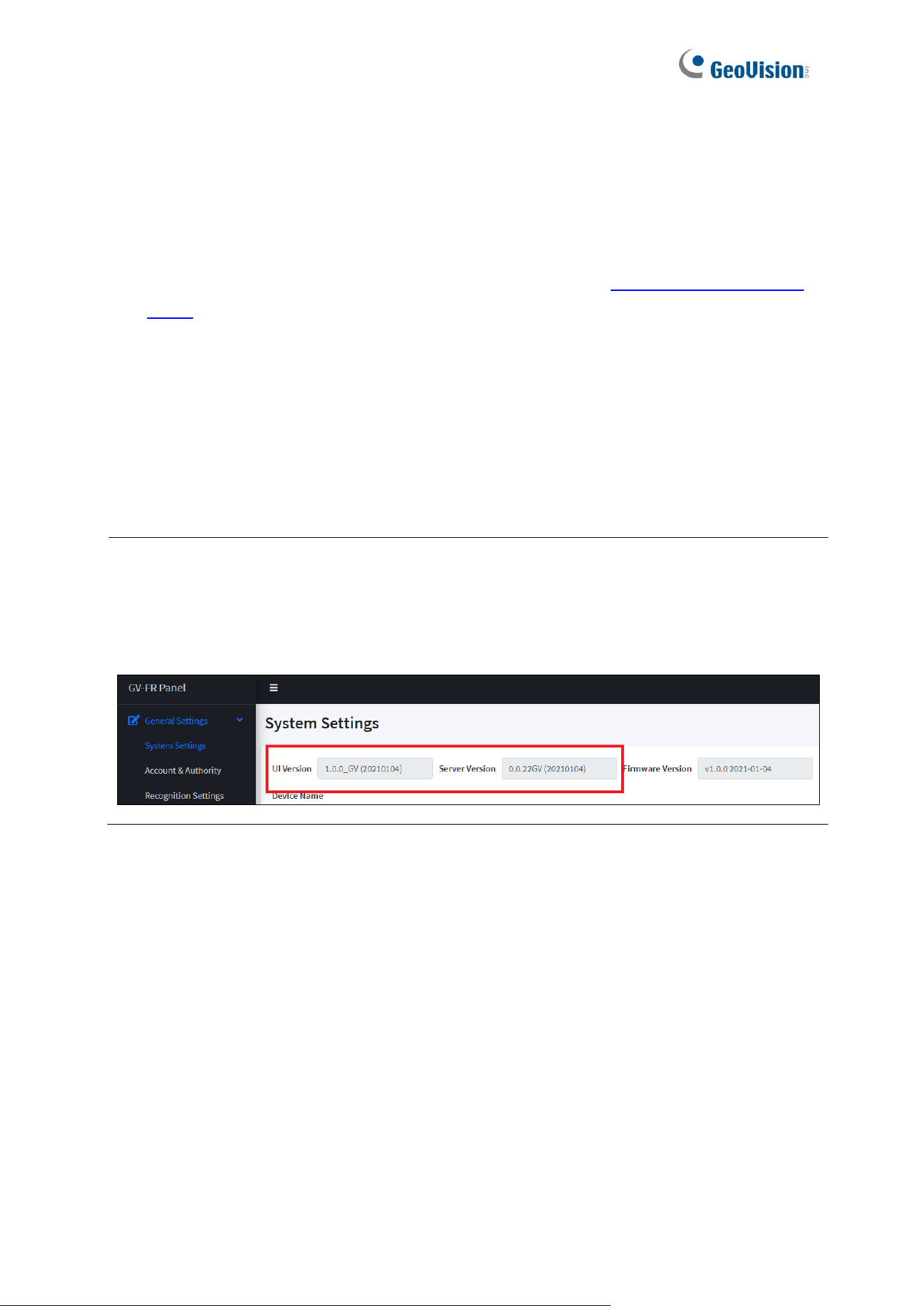
WARNING: Synchronizing and importing face database can only work among the devices
with the same engine versions (UI and Server versions). When applied the face database
with a different engine version, GV-FR Panel will not recognize the faces registered.
You can check the engine versions from the Web interface of GV-FR Panel.
69
Starting GV-Face Manager
You can download GV-Face Manager from the GeoVision’s website.
1. Once downloaded and installed, double-click the Face Manager program to start.
2. Upon first-time startup, you are required to set a login ID and password for the Face
Manager.
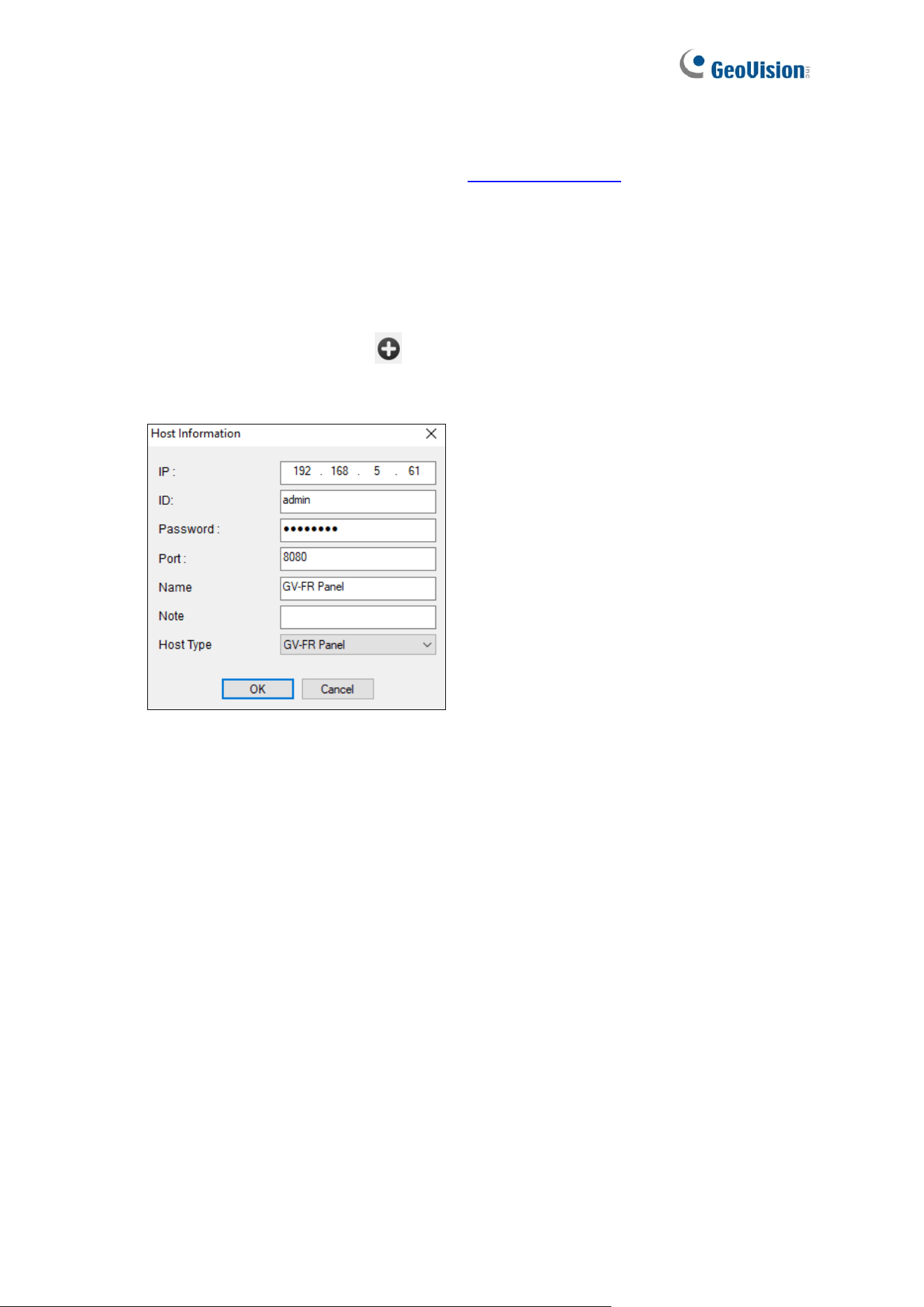
3. After logging in, click Add Host and type the IP address, Port, the login ID and
Password, and type a desired Host Name for the GV-FR Panel, and click OK.
4. Once the GV-FR Panel is added and connected, you can use the Face Manager to
create face profiles, synchronize and back up face databases. For details, see the related
sections in GV-Face Manager User’s Guide, as listed above.

70
Chapter 7 Third-Party Controller Integration
GV-FR Panel is able to transmit access data to and integrate with third-party access control
systems through Wiegand connection. There are two methods to connect GV-FR Panel to a
third-party controller: via the Wiegand interface or the optional GV-FWC face recognition
access data converter.
Note: Facial images from recognition events cannot be transmitted to 3
rd
-party controllers
through Wiegand connection.
71
7.1 Via the Wiegand Interface
Use the Wiegand interface on GV-FR Panel, as indicated below, to connect with a 3
rd
-party
controller.
GV-FR Panel V1:
GV-FR Panel-
Wiegand
3
rd
- party controller
Wiegand
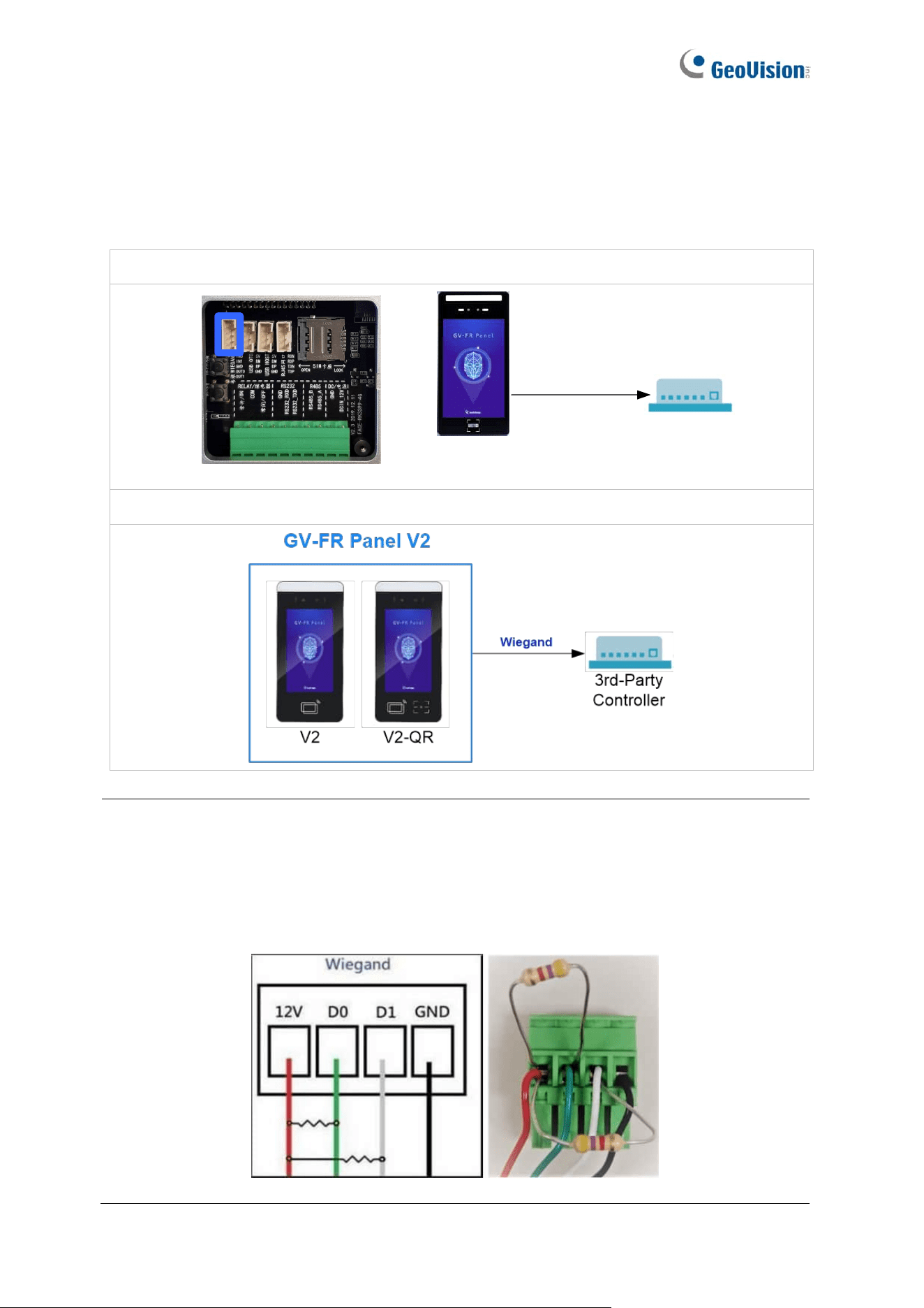
GV-FR Panel V2:
Note: If the third-party controller fails to respond to GV-FR Panel connected via its
Wiegand interface, i.e, the access information received by GV-FR Panel is not transmitted
to the third-party controller, prepare two resistors of 3.3 or 4.7 kΩ, and apply them to the
Wiegand interface. One is between D0 and 12 V, and the other between D1 and 12 V, as
illustrated below.
72
Connection Settings on GV-FR Panel
On the Web interface of GV-FR Panel, select Notify Settings > Event Trigger > New
Trigger, and select Wiegand Output under Trigger Output. When recognition events occur,
card numbers will be transmitted to the controller connected via the Wiegand port.
For details on the Event Trigger settings, see 5.3.2 Event Trigger.
73
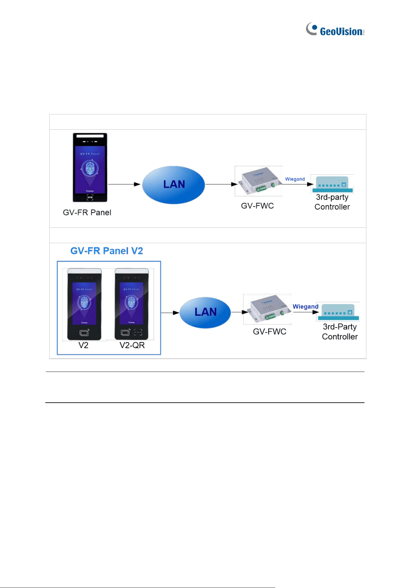
7.2 Via the GV-FWC Converter
Through GV-FWC, a face recognition access data converter, GV-FR Panel is able to send
access data to and integrate with third-party access systems.
GV-FR Panel V1:
GV-FR Panel V2:
Note: Face images of recognition events cannot be sent to 3
rd
-party controllers through
Wiegand connection.
74
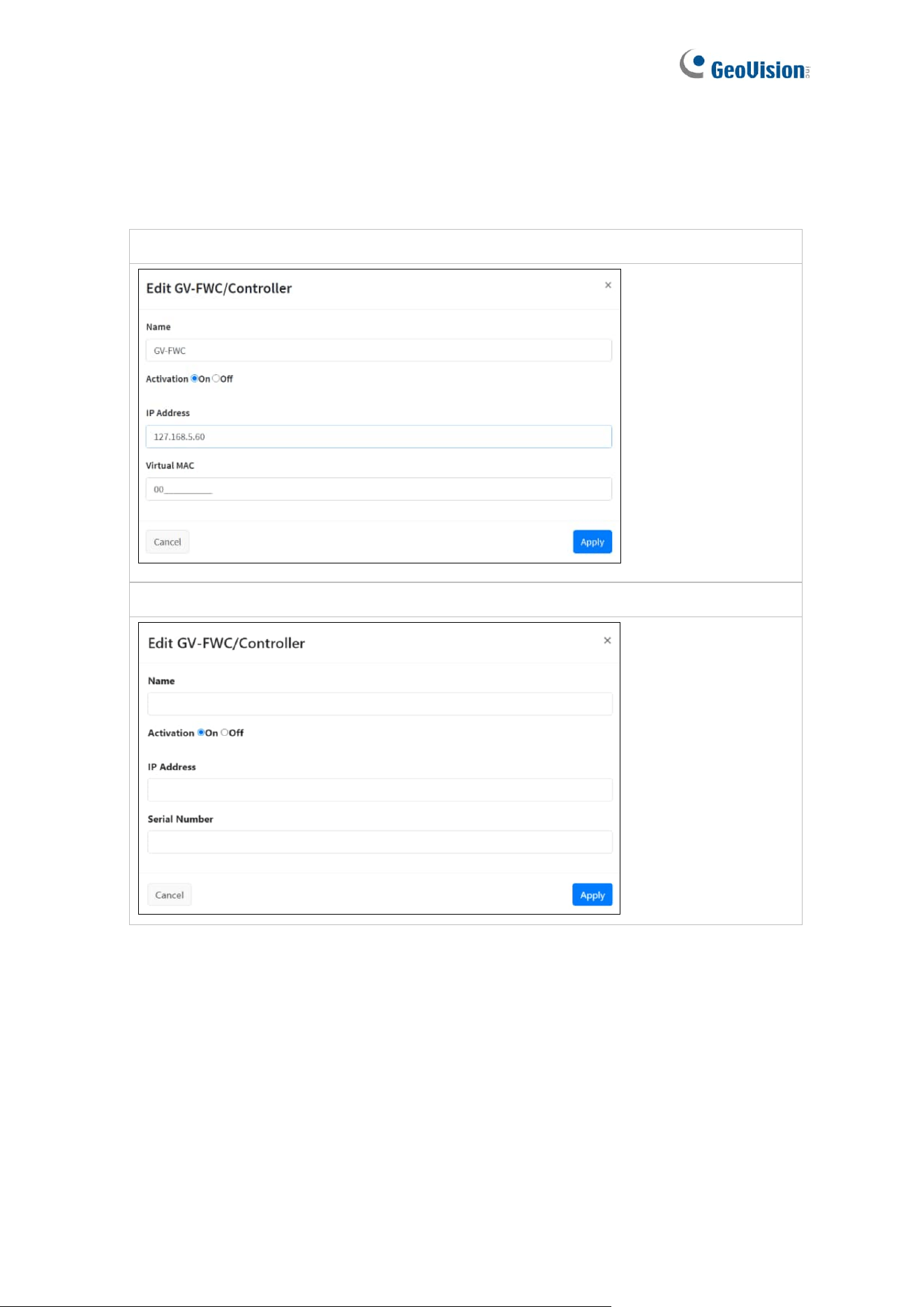
Connection settings on GV-FR Panel
1. On the Web interface of GV-FR Panel, click Notify Settings > GV-FWC/Controller, and
select New GV-FWC/Controller. This dialog box appears.
GV-FR Panel V1:
GV-FR Panel V2:
2. Name the GV-FWC to be connected, type its IP address, and select On next to
Activation to enable connection.
3. Type a 12-numerical long Virtual MAC for GV-FR Panel V1 (Serial Number for GV-FR
Panel V2), with 0 ~ 9, for the GV-FR Panel to be connected to GV-FWC.
4. Click Apply. The GV-FWC/Controller entry is created.
75
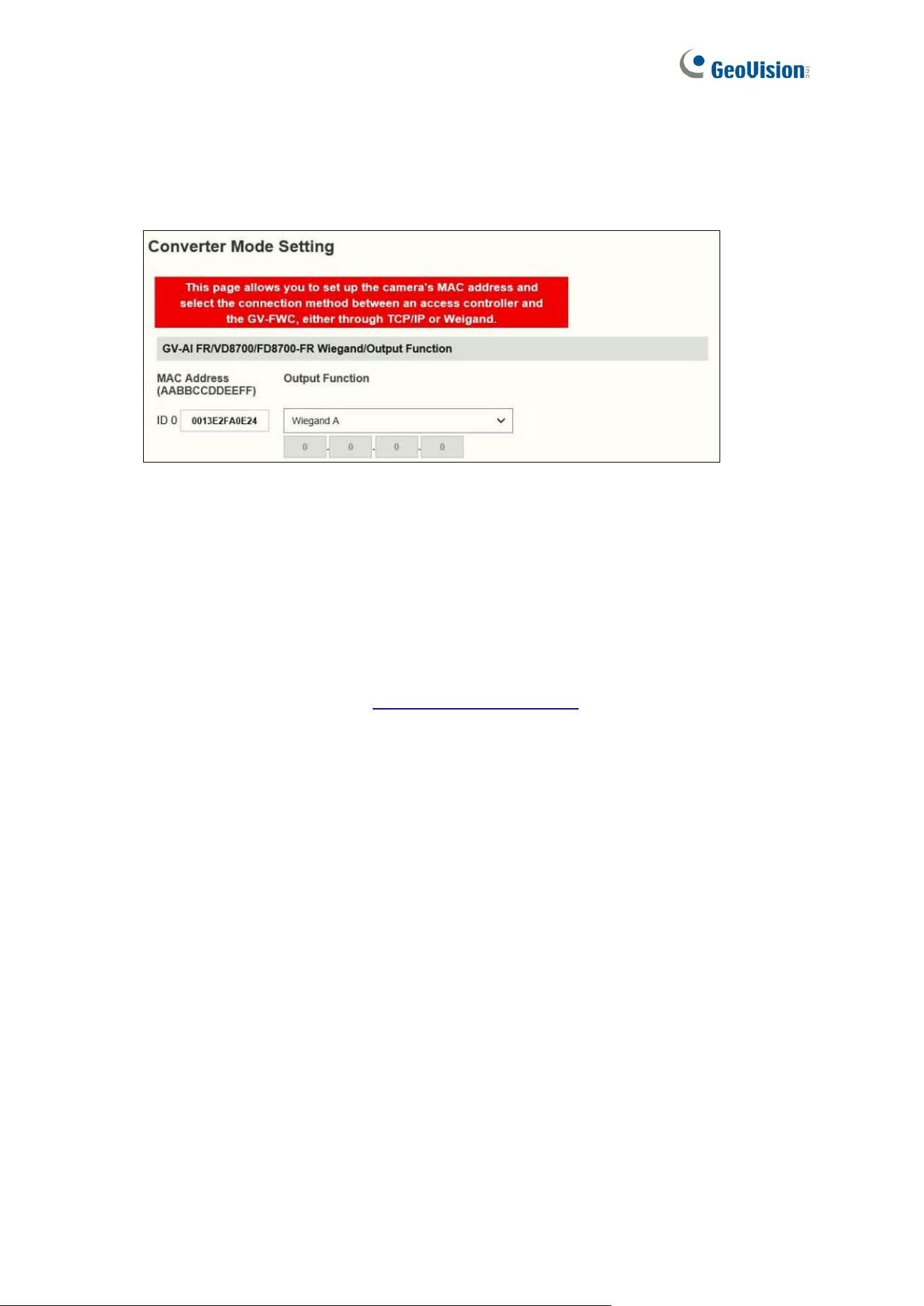
Connection settings on GV-FWC
1. On the Web interface of GV-FWC, click Converter Mode Setting. The Converter Mode
Setting page appears.
2. Under MAC Address, type the MAC address for the GV-FR Panel. See Step 3.
3. Under Output Function, select Wiegand A or Wiegand B where the 3
rd
-party controller
is connected to.
4. Optionally modify the default HTPP Event Port of 8080 if needed.
5. Click Submit to apply the settings.
For more details on GV-FWC, see GV-FWC Installation Guide.
76
Chapter 8 Live Streaming on GV-Software
Once you have connected GV-FR Panel to GV-VMS or to GV-Edge Recording Manager (for
GV-FR Panel V1 only), you can cast GV-FR Panel’s live stream on either software to create
a more comprehensive surveillance management environment.
Note:
1. This function is only applicable to GV-FR Panel V1.40 or later, GV-VMS V17.5.0 /
V18.4.0 or later, and GV-Edge Recording Manager V2.2.0 or later (GV-Edge
Recording Manager only for GV-FR Panel V1).
2. Live streaming is temporarily disabled on GV-Software while users are configuring
GV-FR Panel’s local settings.
3. The talk back function is not supported on GV-Software when connecting to GV-FR
Panel.
4. GV-FR Panel only supports a single stream of 1080 x 1920, 480 x 720, or 480 x 640.
1. Enable Streaming on GV-FR Panel’s local settings to allow the connection to GV-VMS.
Optionally tap Streaming Quality to adjust the video resolution.
2. To add GV-FR Panel on GV-Software:
⚫ For GV-VMS, see Chapter 2 IP Camera Setup in GV-VMS User’s Manual for
details.
⚫ For GV-Edge Recording Manager (only for GV-FR Panel V1), select Add Host >
Add IP Camera. For details, see 2.3.2 Manually Adding a Host in GV-Edge
Recording Manager User’s Manual.
3. Once the connection is established, the live view of GV-FR Panel will appear on GV-
Software.

77
4. To restore the original aspect ratio of GV-FR Panel images:
⚫ On the view window of GV-VMS, click Tools > Properties > Keep Image
Ratio.
⚫ On the view window of GV-Edge Recording Manager (only for GV-FR Panel V1),
click Configure > Properties > Keep Image Ratio.
78
Appendix
Verifying the Connection between GV-FR Panel and GV-AS
Controller
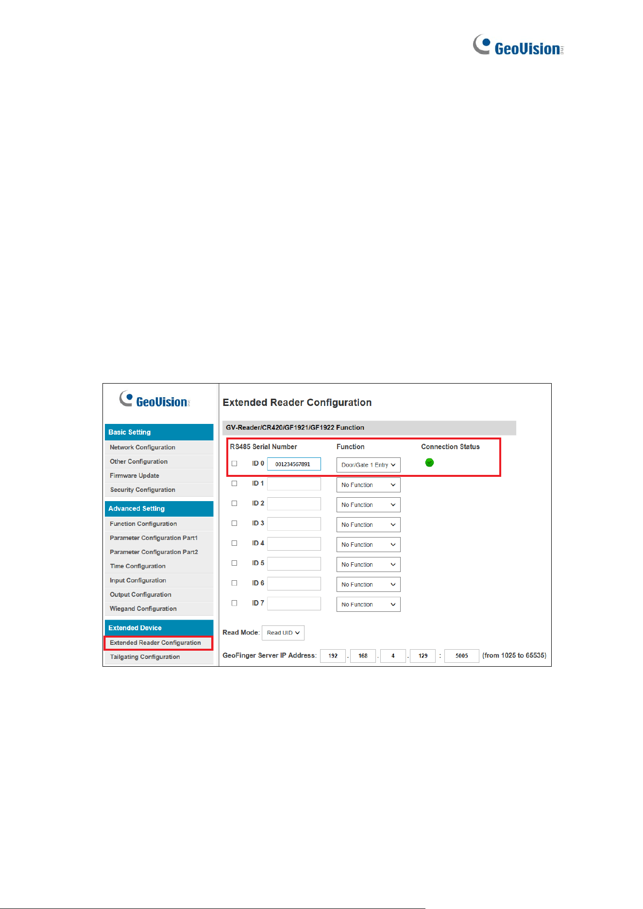
To verify if GV-FR Panel is connected to GV-AS Controller successfully, go to the Web
interface of the GV-AS Controller (Extended Device > Extended Reader Configuration), as
exemplified below, and check the following settings:
⚫ The Virtual MAC of the GV-FR Panel should be listed under Serial Number of the GV-
Reader/CR420/GF1921/GF1922 Function.
⚫ The door corresponding to the GV-FR Panel should be selected under Function.
⚫ The RS-485 checkbox should not be selected.
79
Optional Installation for GV-FR Panel V1
GV-Mount800
You can optionally purchase GV-Mount800 to mount the GV-FR Panel on a surface.
GV-Mount800 Packing List
1. GV-Mount800
2. Securing Nut
3. Screw x 7
4. Hex Wrench
1. Drill a 38-mm (1.50-in) diameter hole on the desired surface for installing the GV-
Mount800.
2. Detach the securing nut from the GV-Mount800.
Securing Nut
3. Place and secure the GV-Mount800 onto the surface by using the securing nut.
80
4. Once the GV-Mount800 is properly installed, place the large sealing rubber of the GV-
FR Panel onto the back of the panel.
5. Attach and secure the GV-FR Panel onto the GV-Mount800 with the 7 screws supplied
to complete the installation.
Sealing Rubber
Note: Thread the necessary cables through the GV-Mount800 and connect them to
the panel before securing the cover.
6. Optionally use the supplied hex wrench to adjust the tilt angle of the GV-Mount800
81
GV-Mount801
You can optionally purchase GV-Mount801 to install the GV-FR Panel at other locations
using the Mobile or Stationary installation.
82
83
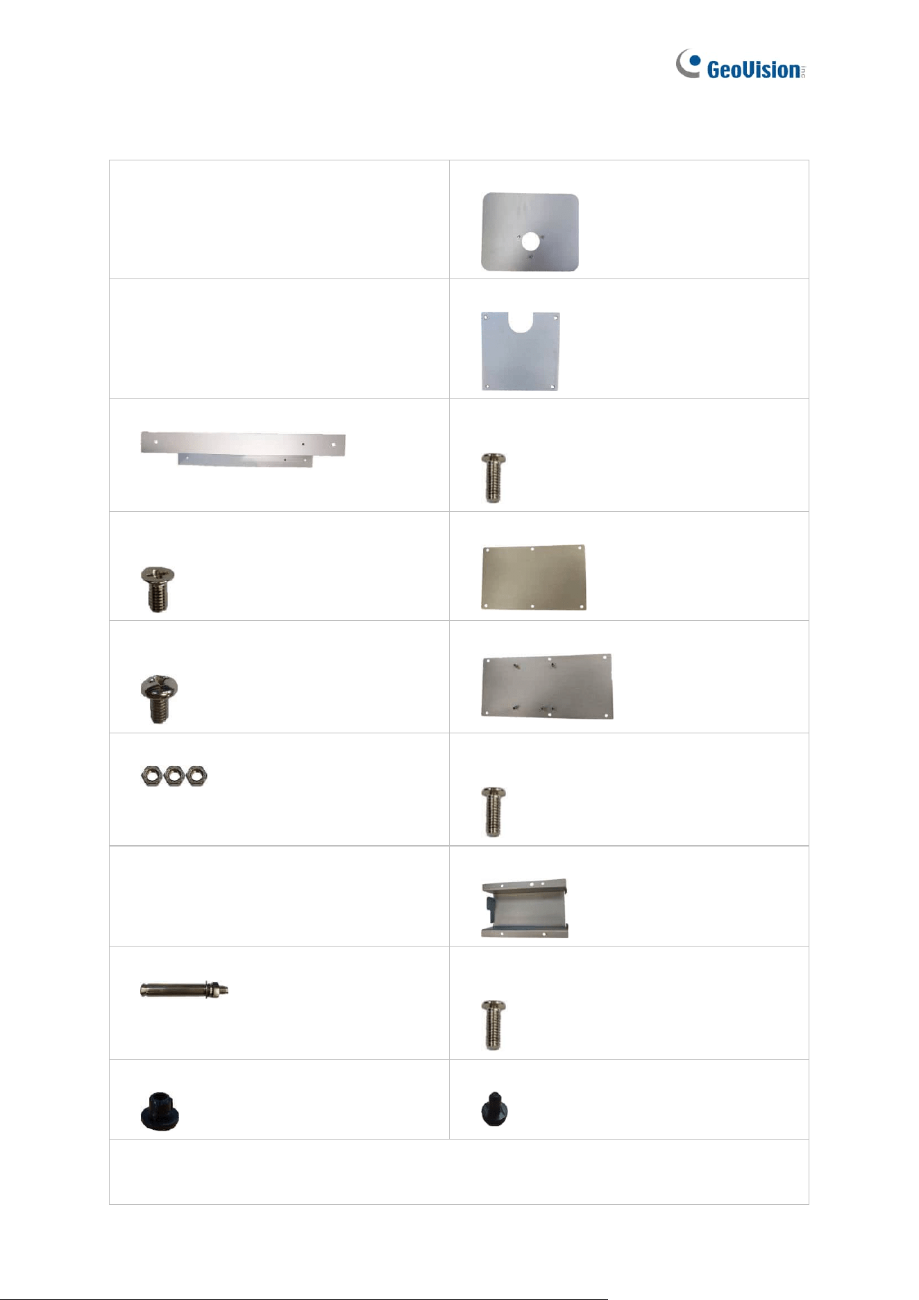
GV-Mount801 Packing List
1. GV-Mount801
2. Mount Base
3. Panel Box Base
4. Mount Base Cover
5. Panel Box Cover
6. Mount Base Cover Screw (M3 x 8 mm
/ 0.12 in x 0.31 in) x 4
7. Panel Box Side Screw (M3 x 6 mm
/ 0.12 in x 0.24 in) x 4
8. Upper Mount Stand Cover
9. Panel Box Base Screw (M4 x 6.5 mm
/ 0.16 in x 0.26 in) x 4
10. Lower Mount Stand Cover
11. Nut x 3
12. Mount Stand Cover Screw (M3 x 8 mm
/ 0.12 in x 0.31 in) x 12
13. Plastic Cover
14. Power Adapter Duct
15. Ground Bolt x 3 (Ground)
16. Power Adapter Duct Screws (M3 x 8 mm
/ 0.12 in x 0.31 in) x 4
17. Large Rubber Plug x 2
18. Small Rubber Plug x 4
Note: The Mount Base Cover Screws, Mount Stand Cover Screws, and Power Adapter
Duct Screws are identical.
84
Mobile Installation
This type of installation allows you to freely install and move your GV-FR Panel from one
place to another. Make sure the power source and network are within reach for connection.
Installing the Mounting Plate to GV-FR Panel
1. Begin by threading the GV-FR Panel’s cable connectors through the following items in
numerical order.
1-1. Large sealing rubber (included in the Wall Mount Bracket Kit, 1.2 Packing List)
1-2. Back cover of the GV-FR Panel
1-3. Small sealing rubber (included in the Wall Mount 1-Bracket Kit, 1.2 Packing List)
1-4. Mounting plate (included in the Wall Mount Bracket Kit, 1.2 Packing List)
2. Embed the large sealing rubber and the back cover onto the back of the GV-FR Panel.
Sealing Rubber
Back Cover
3. Embed the small sealing rubber onto the back cover, and then attach and secure the
mounting plate onto the GV-FR Panel with the back cover screws (included in the Wall
Mount Bracket Kit, 1.2 Packing List).
Sealing Rubber
Mounting Plate
85
Mounting the GV-FR Panel
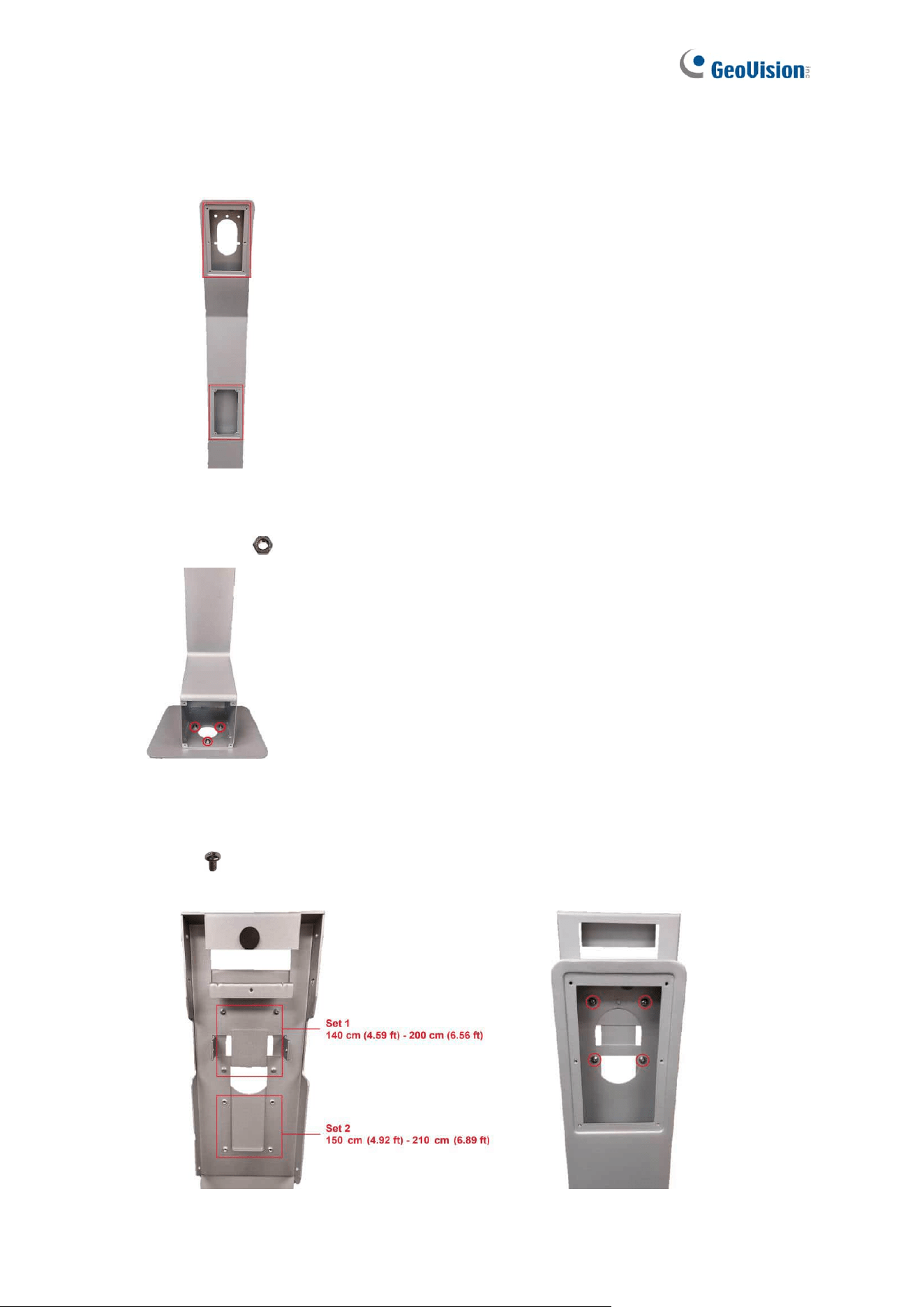
1. Remove both mount stand covers behind the mount stand.
Back of Mount Stand
2. Use a self-prepared hex wrench to secure the mount stand to the mount base with the
supplied nuts at the indicated holes.
Mount Base
3. Align the desired set of holes on the panel box base (Set 1 or Set 2 as illustrated below)
to the four holes on the mount stand, and then insert the supplied panel box base
screws (M4 x 6.5 mm / 0.16 in x 0.26 in) from the upper opening behind the
mount stand to secure them.
Front of Panel Box Base Back of Panel Box Base
86
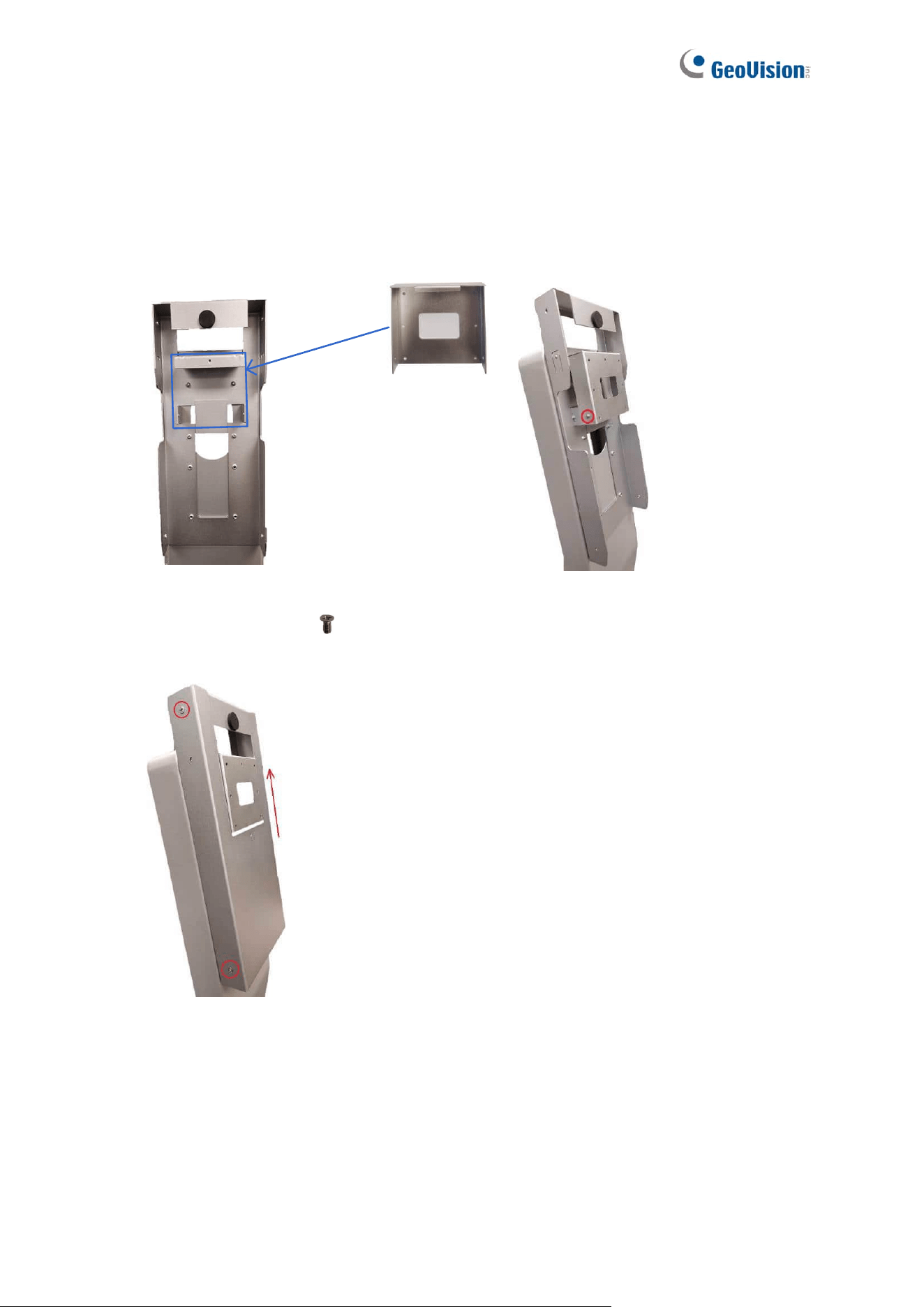
4. To install GV-FR Panel onto GV-Mount801, thread the cables on GV-FR Panel into the
panel box base, and then close the upper mount stand cover.
5. Latch the mounting plate (with GV-FR Panel) onto the protruding part of the panel box
base, and then tighten a mounting plate side screw (included in the Wall Mount Bracket
Kit, 1.2 Packing List) onto each side of the mounting plate.
Mounting Plate
(with GV-FR Panel)
Side of Mounting Plate
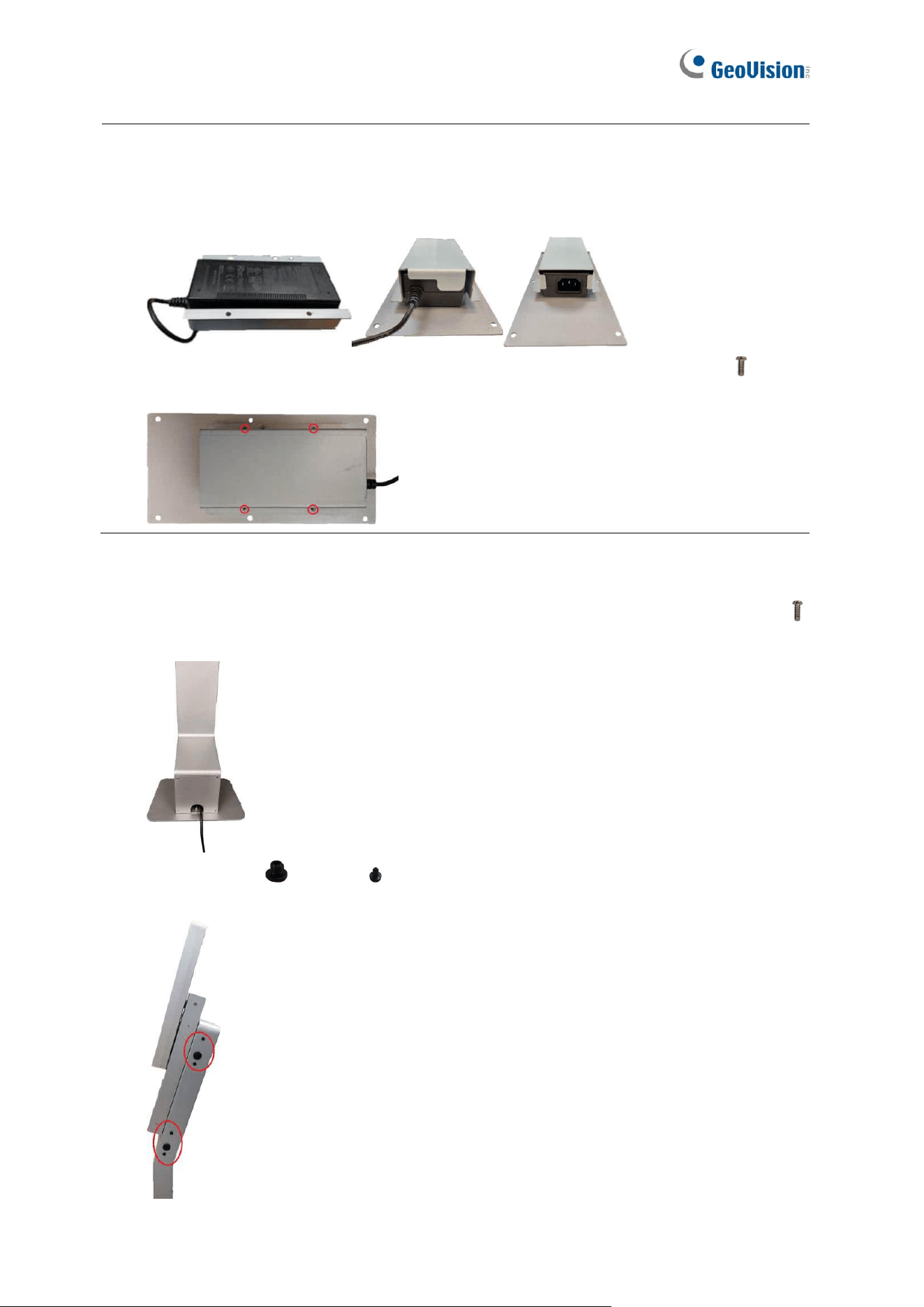
6. Cover the panel box base by sliding the panel box cover from below, and then insert two
panel box side screws (M3 x 6 mm / 0.12 in x 0.24 in) on each side of the panel box
cover to secure the panel box.
7. Use the lower opening behind the mount stand to connect GV-FR Panel to the
necessary power adapter, Ethernet cable or output device. Once done, close the lower
mount stand cover.
87
Note: You can optionally install the power adapter duct on the lower mount stand cover to
secure your power adapter. To do so, follow the steps below.
1. Place the power adapter in the power adapter duct and onto the lower mount stand
cover as shown below.
2. Secure the power adapter duct using the supplied power adapter duct screws (M3 x
8 mm / 0.12 in x 0.31 in).
8. Thread the connected cables further down the mount stand, through the opening at the
mount base, and then close the mount base cover with the mount base cover screws
(M3 x 8 mm / 0.12 in x 0.31 in).
9. Insert the large and small rubber plugs to the side of the mount stand as shown
below.
88
Stationary Installation
This type of installation will fix your GV-FR Panel at a single location. Note the following
precautions before you begin, as the installation requires drilling three permanent holes on a
surface.
⚫ Make sure no other pipes or wires are embedded below the desired surface
⚫ Make sure the network and power source are within reach for connection
⚫ Avoid installing on fragile materials, such as ceramic tiles
1. Follow Step 1 to 4, Mobile Installation to install GV-FR Panel and open the mount stand
covers.
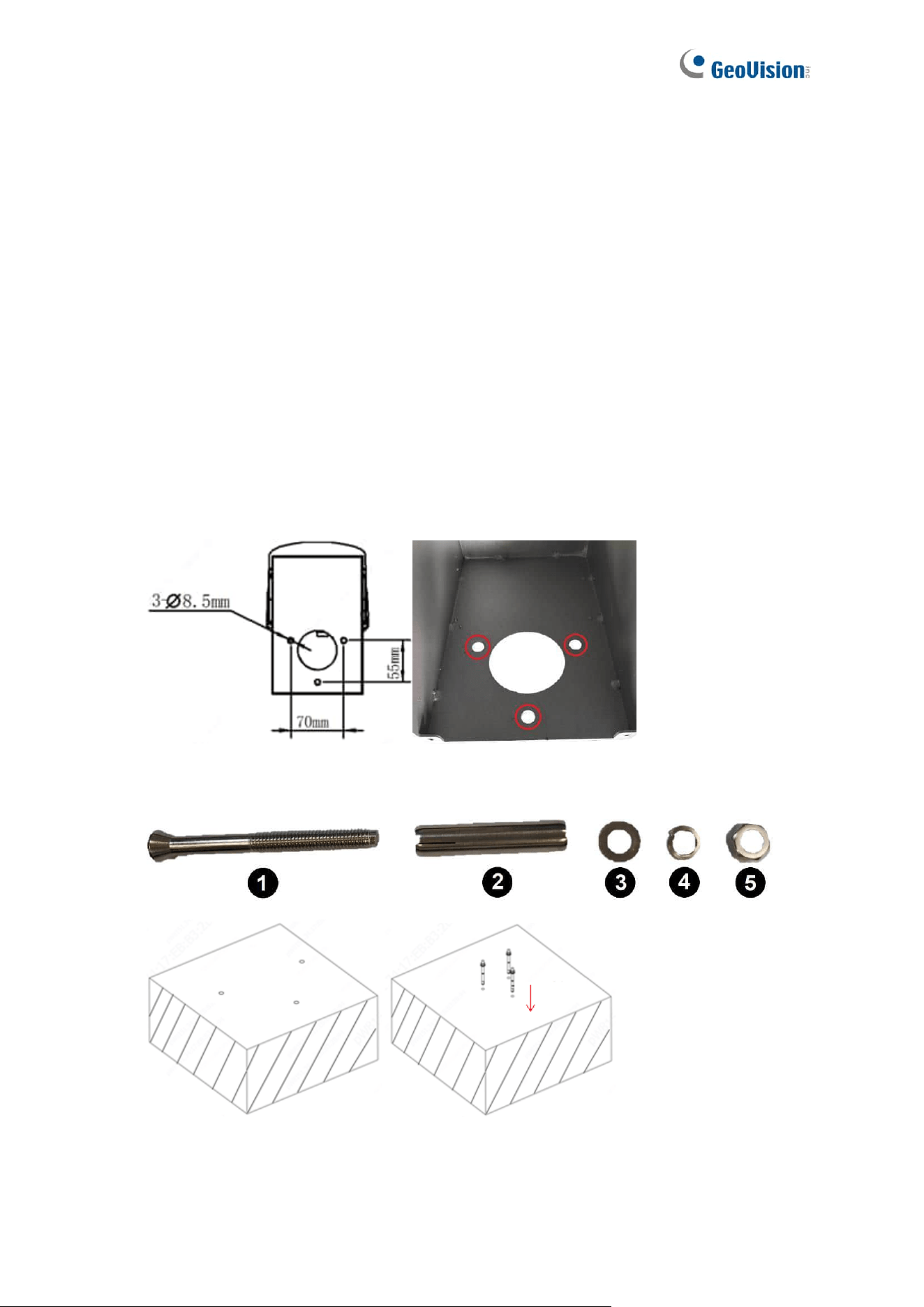
2. Place the mount stand on the desired surface (vertically) and use a marker to mark the
three indicated holes. Use a self-prepared screw gun to drill each hole with a diameter
of 8.5 mm (0.33 in) and a depth of 58 mm (2.28 in).
3. Take apart each ground bolt as shown in the figure below, insert each No. 1 upside
down into the drilled holes, and then fit each No. 2 back on No. 1.
89
4. Use a self-prepared hex wrench to secure the mount stand to the surface with No. 3, 4
and 5 (refer to Step 3).
5. Follow Step 6 to 12, Mobile Installation to complete the GV-Mount801 installation.
90
GV-Mount920
You can optionally purchase the GV-Mount920 to mount the GV-FR Panel on a surface,
power box, or VESA mount.
91
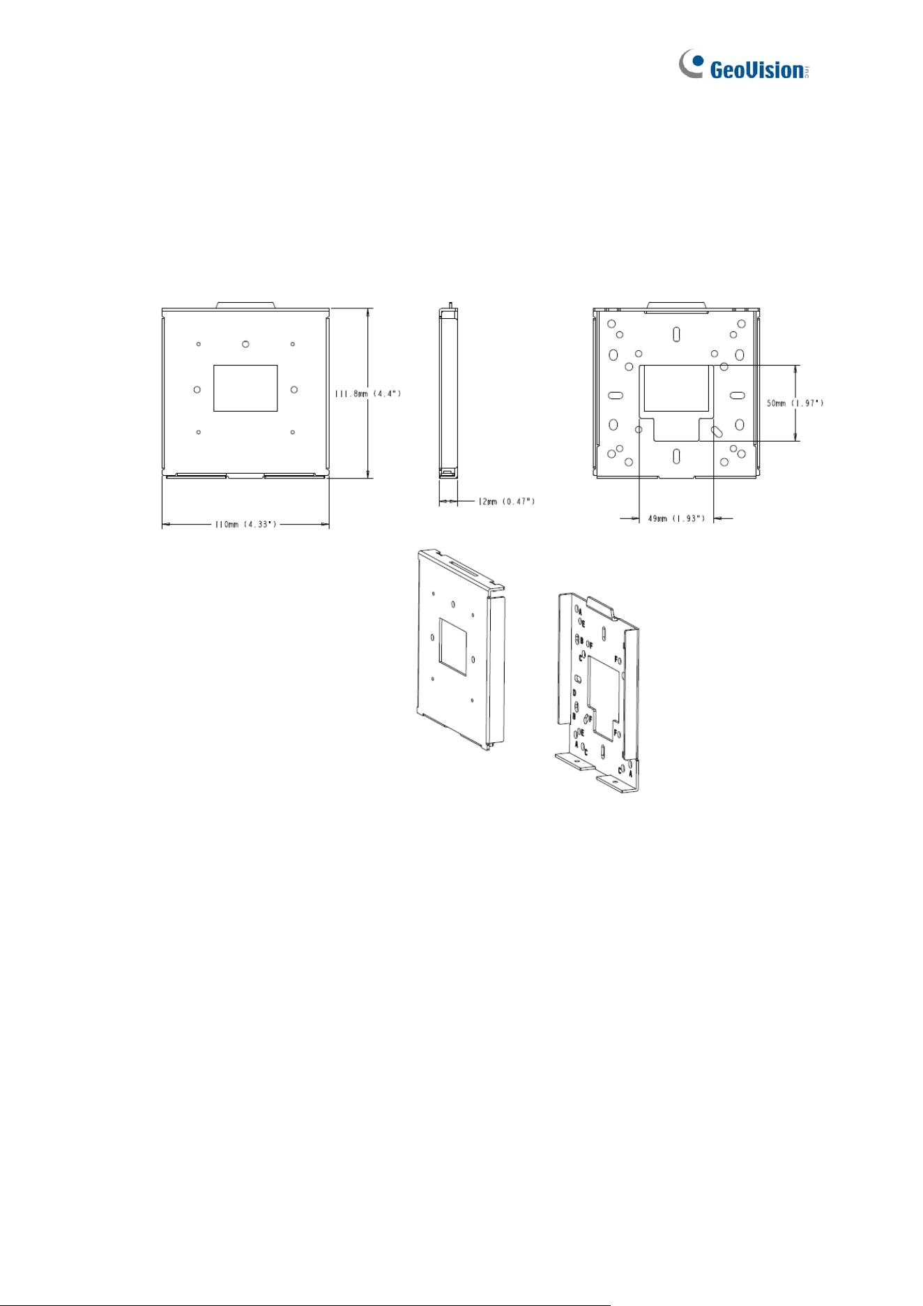
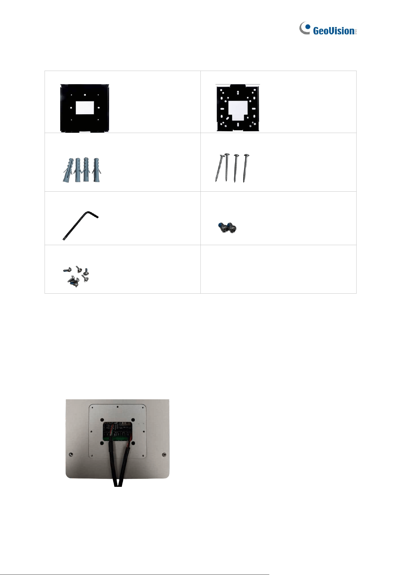
GV-Mount920 Packing List
1. Wall Mount Bracket Top
2. Wall Mount Bracket Base
3. Screw Anchor x 4
4. M3.5xL32 Screw x 4
5. Torx Wrench x1
6. M3x4 Screw x 2
7. M2x6 Screw x 7
Installing the GV-FR Panel to Surfaces
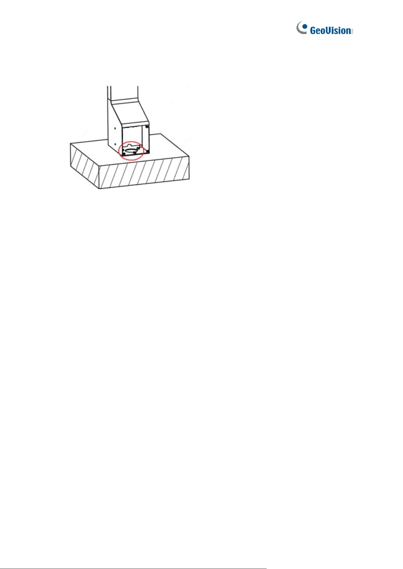
1. Drill holes on the desired surface for installing the GV-Mount920.
2. Place and secure the Wall Mount Bracket Base onto the desired surface with screws
and anchors supplied.
3. Place the back cover with the sealing rubber onto the rear panel of GV-FR Panel.
92
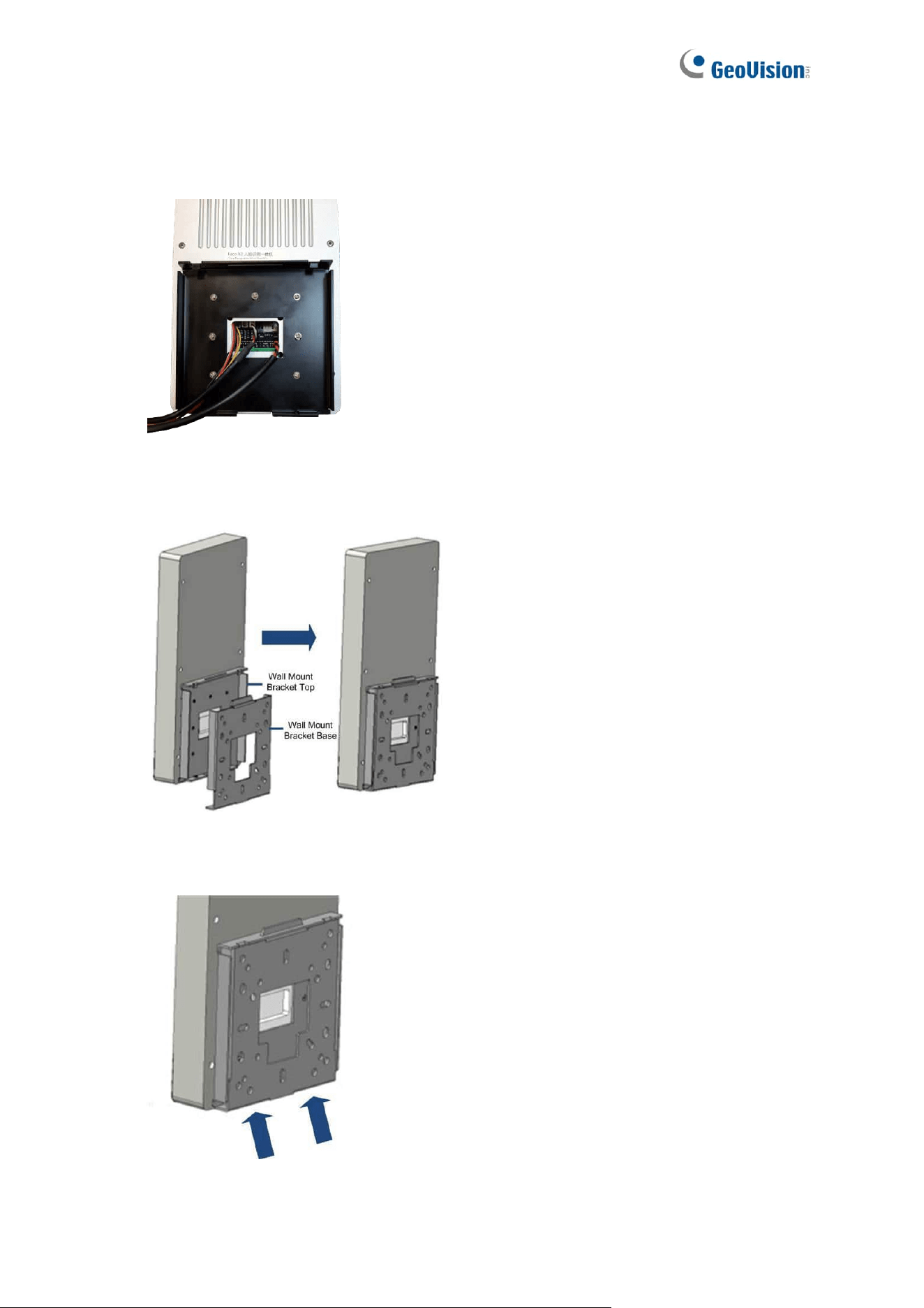
4. Place and secure the Wall Mount Bracket Top onto the rear panel with the 7 M2x6
screws supplied.
5. Tilt the GV-FR Panel and slide it down to integrate the Wall Mount Bracket Top and
Base.
6. Secure the bottom of the Wall Mount Bracket Top and Base with 2 M3x4 screws
supplied and complete the installation.
93
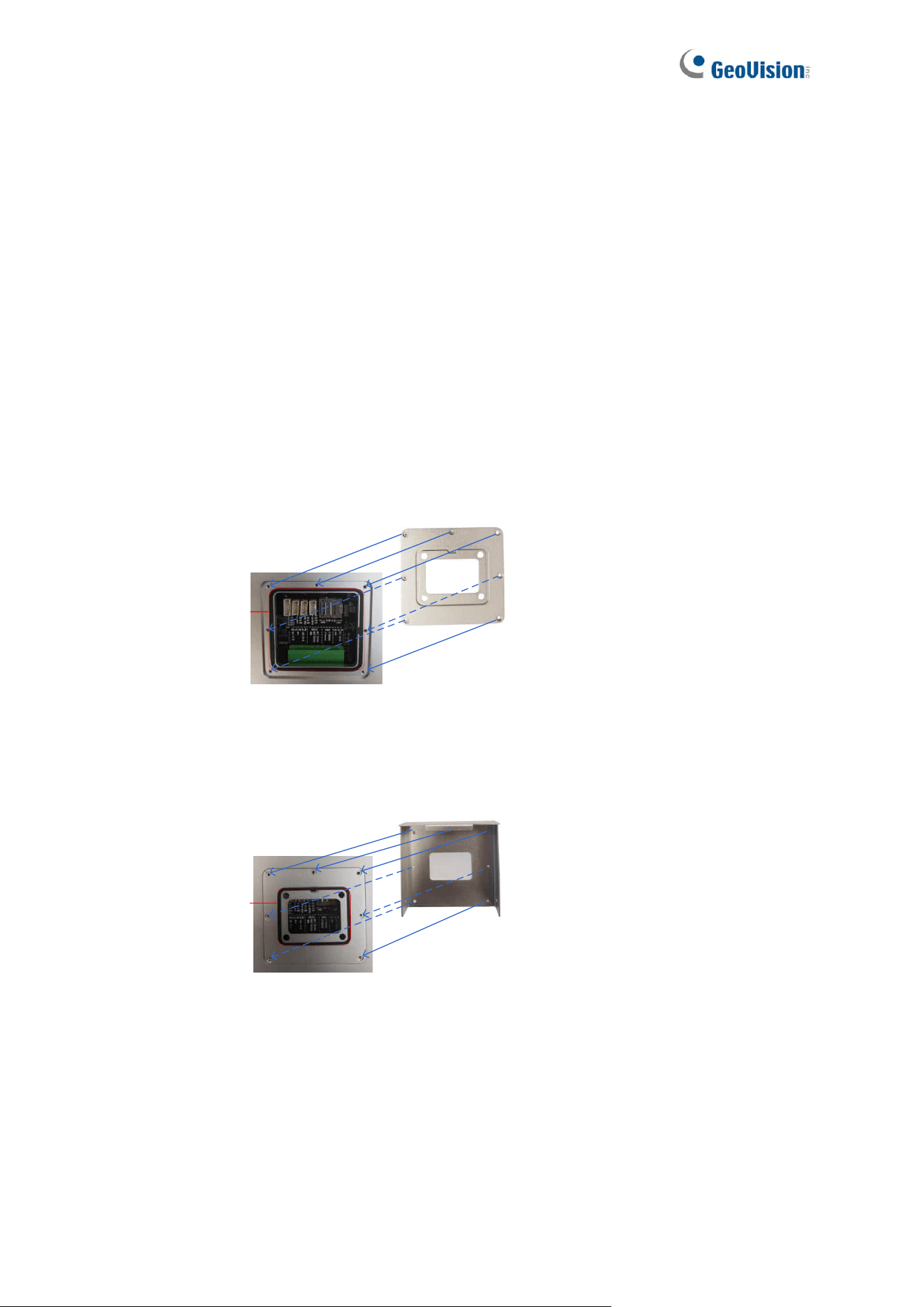
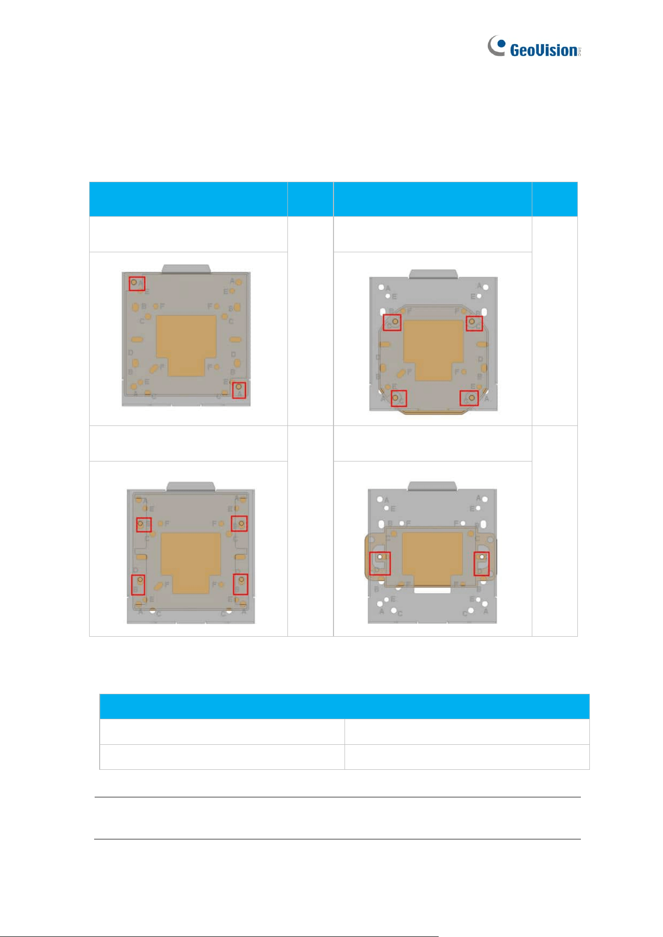
Installing the GV-FR Panel to Different Types of Power Boxes or VESA Mounts
1. The GV-FR Panel can be installed onto 4 types of power boxes with the GV-Mount920.
On the Wall Mount Bracket Base, the corresponding holes for each type are marked
with A-F:
Type of Power Box
Hole
Type of Power Box
Hole
4’’ Square
A
Double Gang
B
4’’ Octagon
C
Single Gang
D
2. To install the GV-FR Panel onto VESA mounts with the GV-Mount920, 2 types of screw
holes are applicable:
Type of Screw Hole
75 x 75 mm (2.95 x 2.95 in) VESA Mount
Hole E
50 x 50 mm (1.97 x 1.97 in) VESA Mount
Hole F
Note: The screws for installing the GV-Mount920 onto power boxes or VESA mounts
are not included in the kit.