
McIntosh Laboratory, Inc. 2 Chambers Street Binghamton, New York 13903-2699 Phone: 607-723-3512 www.mcintoshlabs.com
M C 2 .1K WM C 2 .1K W
POWER AMPLIFIER
OWNER’S MANUAL

2
Thank You from all of us at McIntosh
You have invested in a precision instrument that
will provide you with many years of enjoyment.
Please take a few moments to familiarize yourself
with the features and instructions to get the
maximum performance from your equipment.
If you need further technical assistance, please
contact your dealer who may be more familiar with
your particular setup including other brands. You
can also contact McIntosh with additional questions
or in the unlikely event of needing service.
McIntosh Laboratory, Inc.
2 Chambers Street
Binghamton, New York 13903
Technical Assistance (607) 723-3512
Fax (607) 724-0549
Customer Service (607) 723-3515
Fax (607) 723-1917
Email support@mcintoshlabs.com
Website www.mcintoshlabs.com
Introduction
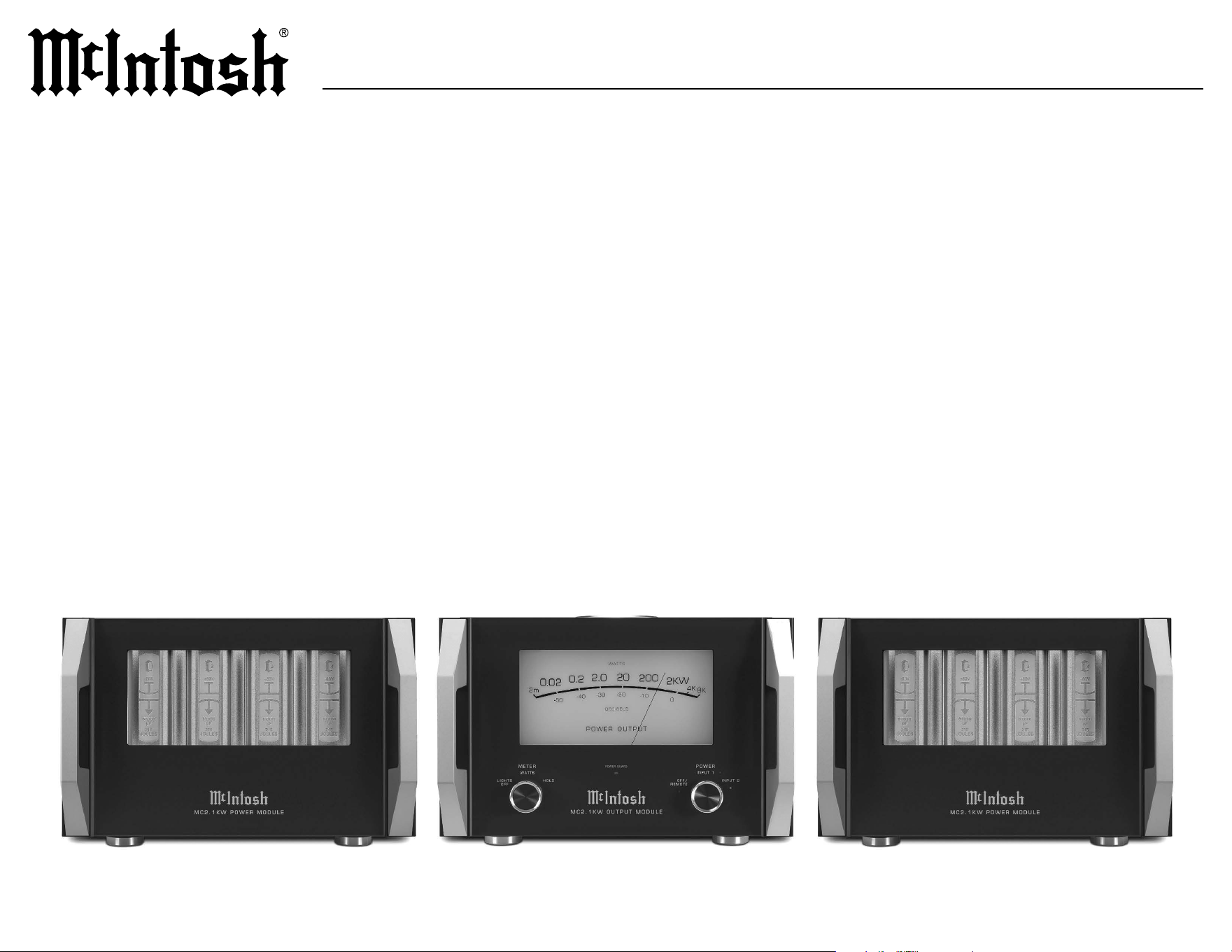
The McIntosh MC2.1KW Monoblock Power
Amplier is the ultimate power in home audio
amplication. The pinnacle of audio amplica
-
tion, the MC2.1KW stands as a testament to our
unwavering commitment to sonic perfection. This
tri-chassis marvel possesses the remarkable ability
to deliver an astonishing 2,000 Watts of pristine
McIntosh power, forever transforming your home
stereo or theater experience. At McIntosh, we don’t
just appreciate sound – we are Made of Sound™.
Safety First
Please read the safety instructions included in a
separate document called Important Additional
Operation Information Guide.
Please Take A Moment
For future reference, you can write down your
serial number and purchase information here. We
can identify your purchase from this information if
the occasion should arise:
Serial Number: __________________________
Purchase Date: ___________________________
Dealer Name: ___________________________
Table of Contents
Thank You from all of us at McIntosh .. .. .. 2
Introduction . .. .. .. .. .. .. .. .. .. .. .. .. .. 2
General Information .. .. .. .. .. .. .. .. .. .. 3
Performance Features.. .. .. .. .. .. .. .. .. .. 4
Dimensions .. .. .. .. .. .. .. .. .. .. .. .. .. 5-7
Front Panels .. .. .. .. .. .. .. .. .. .. .. .. .. 8-9
Rear Panels .. .. .. .. .. .. .. .. .. .. .. .. .10-11
Connecting the Modules .. .. .. .. .. .. .. .12-13
Inserting and Locking the Cables .. .. .. .. ..12
Connecting the Cables .. .. .. .. .. .. .. .. ..13
Connecting a Single Preamplifier .. .. .. .. ..14
XLR Connectors . .. .. .. .. .. .. .. .. .. .. .. 14
RCA Connectors . .. .. .. .. .. .. .. .. .. .. ..14
Power Control Connectors .. .. .. .. .. .. .. ..14
Connecting Two Preamplifiers .. .. .. .. .. ..15
Connecting a Loudspeaker.. .. .. .. .. .. .16 -17
Loudspeaker Impedance. .. .. .. .. .. .. .. .. 16
Loudspeaker Cables .. .. .. .. .. .. .. .. .. ..16
Output Terminals .. .. .. .. .. .. .. .. .. .. .. 16
Output Terminal Covers . .. .. .. .. .. .. .. .. 16
Loudspeaker Cable Connections .. .. .. .. ..17
System Specifications .. .. .. .. .. .. .. .. .. ..18
Power Module Specifications .. .. .. .. .. .. ..18
Output Module Specifications .. .. .. .. .. ..18
Packing Instructions .. .. .. .. .. .. .. .. .. ..19
Parts List .. .. .. .. .. .. .. .. .. .. .. .. .. .. ..19

3
MC2.1KW
General Information
5. In the event that either or both MC2.1KW
Power Modules overheat, the thermal protec-
tion circuits will activate, s
h
ould this happen,
the sound will be muted, and the MC2.1KW
Output Module Power Guard LED will illumi
-
nate. When the MC2.1KW Power Modules have
returned to a safe operating temperature, normal
operation will resume.
6. The MC2.1KW loudspeaker negative
connections are above chassis ground. Do not
combine any connections together, ground
them or connect with another MC2.1KW
Power Amplier.
7. Each MC2.1KW Power Module connects
to the MC2.1KW Output Module with two
dierent interconnect cables. Do not use any
other cable when connecting the MC2.1KW
Output Module to the MC2.1KW Power
Modules. These cables are for use only with
the MC2.1KW Power Amplier. If all cables
are not connected correctly, the MC2.1KW
Power Amplier will not power up. Refer to
pages 12 and 13 for additional information on
connecting the MC2.1KW Power Modules to the
MC2.1KW Output Module.
1. The MC2.1KW Power Module weight is 145
pounds (65.8 kilograms) and the MC2.1KW
Output Module weight is 125 pounds (56.7
kilograms). It requires two or more persons
to safely handle when moving the Power or
Output Module.
2. Each of the MC2.1KW Power Modules needs
to be connected to a dedicated AC circuit.
The MC2.1KW Output Module should be
connected to a third separate AC circuit. The
third AC circuit may have other components
connected, including additional MC2.1KW
Output Modules. Contact your McIntosh dealer
and a certied electrician for additional informa
-
tion and assistance.
3. The AC power cables going to the MC2.1KW
Power Modules, MC2.1KW Output Module
and all other components should not be
connected to AC power until all system
components are connected together.
4. Always provide adequate ventilation for the
MC2.1KW Output and Power Modules. Each
module should be installed upright and on
its feet. Do not install any of the modules
directly above any type of heat generating
component. For the MC2.1KW Output Module
allow at least 2 inches (5.1cm) of space above the
top and 2 inches (5.1cm) of space on each side.
For the MC2.1KW Power Modules allow at least
6 inches (15.2cm) of space above the top and 2
inches (5.1cm) of space on each side.
8. It is important to keep your McIntosh unit out
of direct sunlight and only use appropriate
gentle cleaners because the Organic Anodize
can become discolored over time. While most
products will maintain their classic dark features
for their lifetime, some situations can accelerate
discoloration. The most pervasive culprit is UV
light, especially light directly from the sun, or
high intensity spotlights. Even high intensity
short-term exposure can result in discoloration.
Chemicals can also alter the nish of the
Anodize. Aggressive cleaners will take their toll
over time and actually etch away the Anodize
nish.
9. The MC2.1KW has been tested and certied
for indoor use only.

4
Performance Features
• Quad Balanced Design
The MC2.1KW consists of one Output Module
and two Power Modules each containing its own
1,000 Watt amplier. The incoming audio signal
enters the Output Module from the preamplier.
An in-phase signal is sent to one of the Power
Modules and amplied while an out-of-phase
signal is sent to the other Power Module and
amplied. Both amplied signals exit the
Power Modules and reenter the Output Module
where they drive opposite ends of the bi-lar
wound McIntosh Autoformer. This combines
the amplied signals back into one at twice
the power. Through this artful engineering, a
low distortion audio signal leaves the Output
Module to deliver pristine sound through your
loudspeaker.
• Power Output
The MC2.1KW Power Amplier is capable of
2,000 Watts into a 2, 4, or 8 ohm loudspeaker
with less than 0.005% distortion. It can provide
peak current of 200 amperes and over 8,000
Watts of power output on music bursts.
• ThermalTrak™ Power Transistors
The MC2.1KW uses a total of 96 ThermalTrak
Power Transistors in the Power Modules for
fast thermal bias tracking. This is accomplished
using a thermally matched bias diode that is part
of the transistor die itself thereby eliminating
any delay in establishing thermal equilibrium.
ThermalTrak™ is a trademark of Semiconductor
Components Industries, LLC.
• Illuminated Glass Front Panel
The famous McIntosh illuminated front panel
is made from 1/2 inch thick glass and uses Light
Emitting Diodes (LEDs) for even illumination
and long life.
• Illuminated Power Meter
The Illuminated Power Output Meter is peak
responding and indicates the true power output
of the amplier. A choice of displaying either the
dynamic power output or displaying peak hold is
available. Meter lighting can also be controlled
from the front panel or remotely.
• Remote Power Control
McIntosh power control circuits allow for remote
turn on/o of the MC2.1KW Power Amplier
from a McIntosh preamplier or A/V control
center. Meter illumination can also be controlled
remotely using the preamplier or A/V control
center’s trim menu.
• Independent Power Supplies
The MC2.1KW Output Module uses a low noise
R-Core power transformer with fully regulated
power supplies for powering the low-level audio,
control and illumination circuits. Each MC2.1KW
Power Module uses a large toroidal power
transformer and large lter capacitors with a total
of 860 Joules of energy.
• Dual Inputs for Advanced System Congurations
The MC2.1KW has dual sets of balanced and
unbalanced inputs, conveniently allowing you to
connect more than one preamplier. This gives
you the ability to easily switch between preamps
of dierent types such as vacuum tube and
solid-state.
• Power Guard
®
The patented McIntosh Power Guard circuit
prevents the amplier from being overdriven into
clipping. Clipping produces a harsh distorted
sound and can also damage loudspeakers.
• Sentry Monitor™
The McIntosh Sentry Monitor circuit monitors
amplier output current to keep it within a safe
range should a short or improper load be present
on the amplier output.
• Monogrammed Heatsinks™
The McIntosh designed Monogrammed Heatsinks
ensure thorough and even heat dissipation in the
Power Module output stage. Thermal protection
is provided for each heatsink should there be
inadequate ventilation.
• Proprietary Autoformer™
The McIntosh designed and manufactured output
Autoformer provides an ideal match between
the Power Module output stage and loudspeaker
loads of 2, 4, and 8 ohms. The Autoformer
also provides perfect DC protection for your
loudspeakers.
• Solid Cinch™ Binding Posts
Our patented Solid Cinch binding posts easily
but securely attach the loudspeaker cables for a
solid connection. The posts are gold-plated to
prevent corrosion and ensure a quality signal is
sent over your loudspeaker cables. There are three
sets of binding posts for each of the three output
impedances. This allows for easy bi or tri-wiring
of a loudspeaker.
5
MC2.1KW
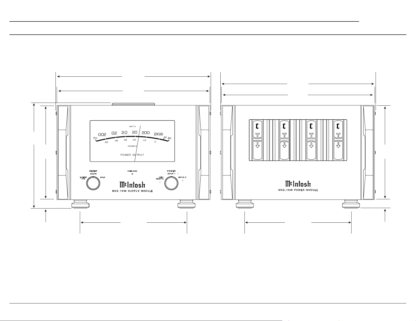
Dimensions
1
-80V
215
JOULES
67,000
μF
2
+80V
215
JOULES
67,000
μF
+80V
215
JOULES
67,000
μF
4
-80V
215
JOULES
67,000
μF
3
M
C 2 . 1 K W P O W E R M O D U L E
PO WER GUA RD
M E T E R
W A T T S
L I G H T S
O F F
H O L D
I N P U T 1
O F F /
R E M O T E
P O W E R
I N P U T 2
M C 2 . 1 K W O U T P U T M O D U L E
45.6cm
17 15/16”
44.9cm
17 11/16”
45.6cm
17 15/16”
44.9cm
17 11/16”
31.1cm
12 1/4”
31.1cm
12 1/4”
30.9cm
12 5/32”
27.6cm
10 7/8”
1”
1”
27.6cm
10 7/8”
2.5cm
2.5cm
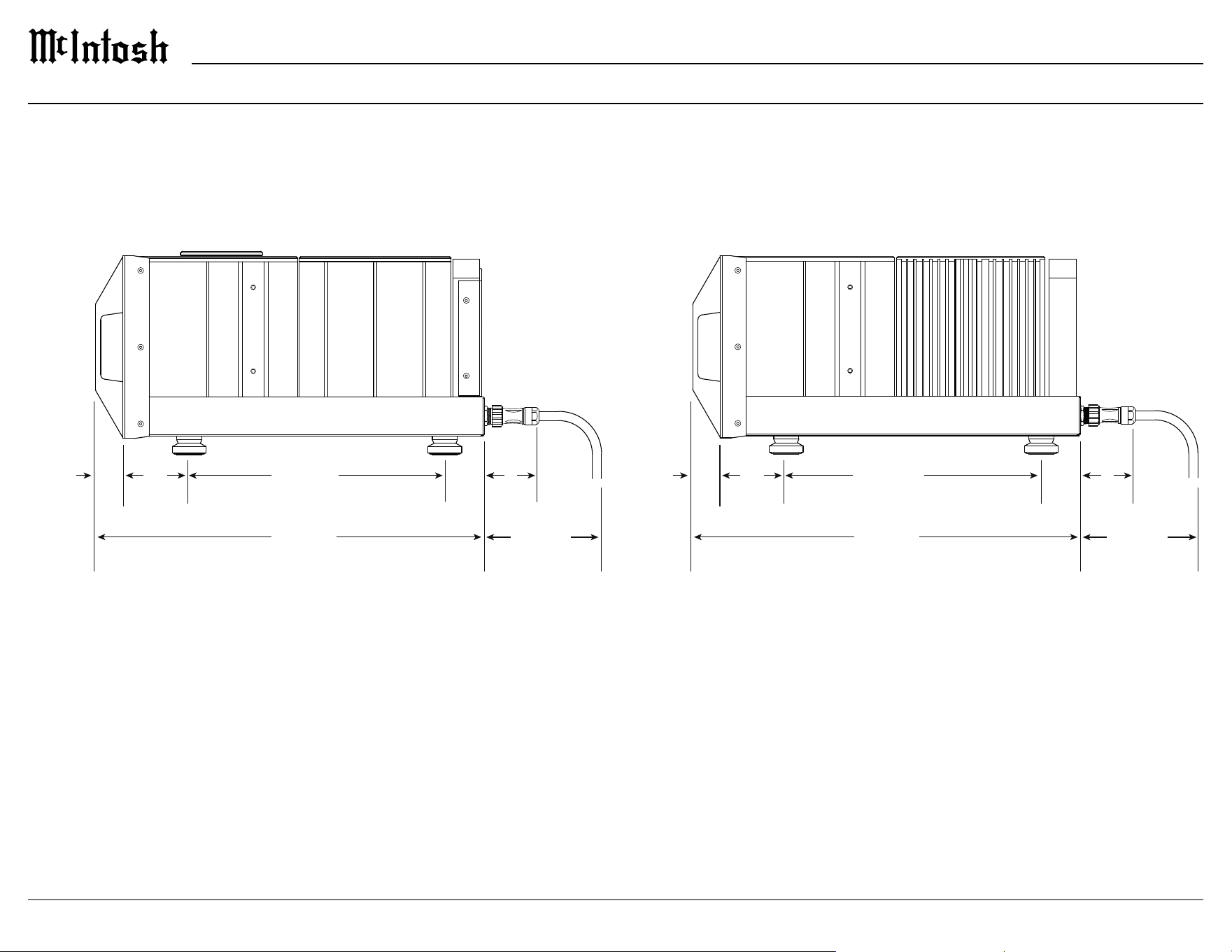
6
58.9cm
23 3/16”
10.1cm
3 31/32”
38.7cm
15 1/4”
8.6cm
3 3/8”
17.8cm
7”
58.9cm
23 3/16”
10.1cm
3 31/32”
4.1cm
1 5/8”
38.7cm
15 1/4”
8.6cm
3 3/8”
17.8cm
7”
4.1cm
1 5/8”
Dimensions (continued)
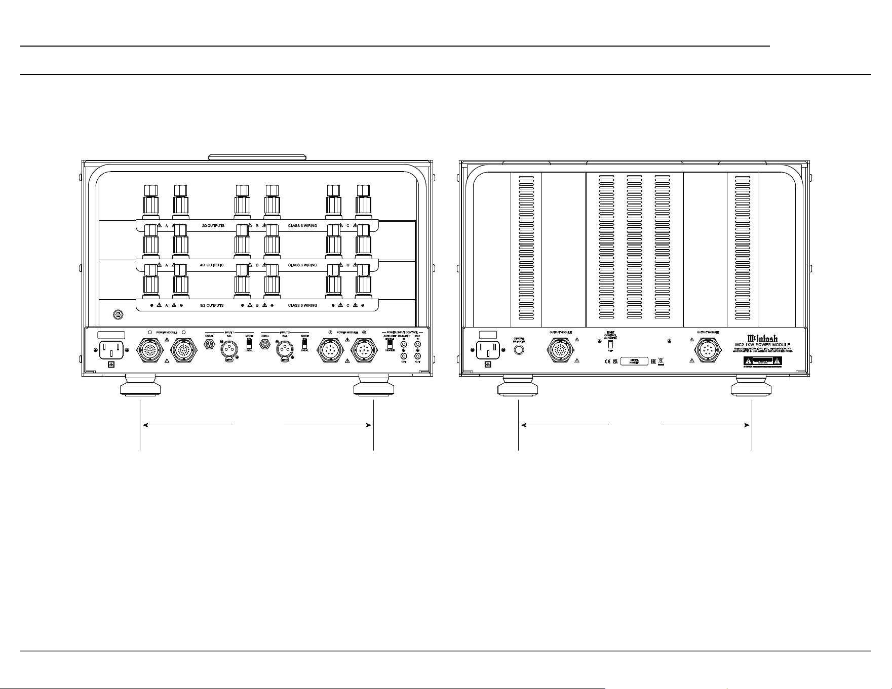
7
MC2.1KW
FUSE
FUSE
PUSH
PUSH
UNBAL
BAL
MODE
INPUT 1
BAL
UNBAL
POWER MODULE
A B
UNBAL
BAL
MODE
INPUT 2
BAL
UNBAL
DISABLE
ENABLE
AUTO OFF
IN
MAIN / IN 1
IN
IN 2
OUT OUT
POWER MODULE
A B
POWER / INPUT CONTROL
A
B
CLASS 3 WIRING
C
A
B
C
A
+
-
B
+
-
C
+
-
CLASS 3 WIRING
CLASS 3 WIRING
2Ω
OUTPUTS
4Ω
OUTPUTS
8Ω
OUTPUTS
OUTPUT MODULE OUTPUT MODULE
CIRCUIT
BREAKER
McINTOSH LABORATORY, INC. BINGHAMTON, NY
HANDCRAFTED IN USA WITH US AND IMPORTED PARTS
MC2.1KW POWER MODULE
SERIAL
NUMBER
CCAAUUTTIIOONN
OFF
ON / METER
LIGHT
CONTROL
11 3/4” 11 3/4”
29.8cm 29.8cm
Dimensions (continued)
8
Front Panels
1
-80V
215
JOULES
67,000
μF
2
+80V
215
JOULES
67,000
μF
+80V
215
JOULES
67,000
μF
4
-80V
215
JOULES
67,000
μF
3
M
C 2 . 1 K W P O W E R M O D U L E
PO W E R G U ARD
M E T E R
W A T T S
L I G H T S
O F F
H O L D
I N P U T 1
O F F /
R E M O T E
P O W E R
I N P U T 2
M C 2 . 1 K W O U T P U T M O D U L E

9
MC2.1KW
Front Panels (continued)
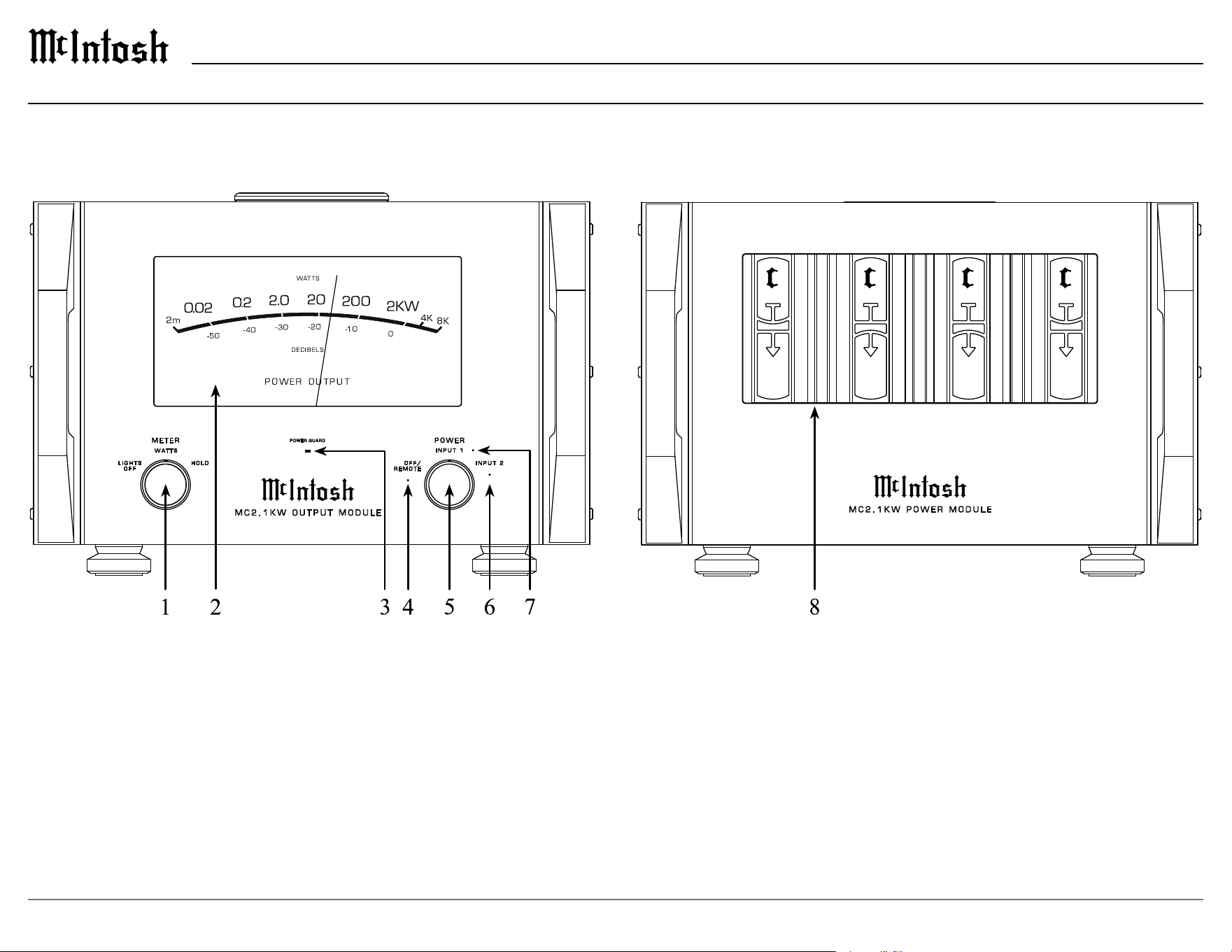
1. METER Control Knob
LIGHTS OFF - The meter operates as if in
th
e WATTS position, but meter illumination is
turned o.
WATTS - The meter dynamically responds to
power output.
HOLD - The meter will hold the highest power
o
u
tput peak then gradually decay until a higher
peak is reached.
When in the WATTS or HOLD position, meter
illumination can be controlled from a preampli-
er with meter light control capabilities if there
i
s a p
ower control connection. Refer to pages 14
and 15 for making a power control connection.
2. POWER OUTPUT Meter
Displays the power output in WATTS (top scale)
an
d DECIBELS (bottom scale).
3. POWER GUARD Indicator
The POWER GUARD indicator will illuminate
under the following conditions:
• When the Power Guard circuit activates to
control excessive distortion in the audio output.
• When the audio is muted due to high
temperatures in any of the Power Module heatsinks.
• When the audio is muted during the MC2.1KW
power on sequence (approximately 4 seconds).
4. OFF/REMOTE Indicator
Indicates that the MC2.1KW is in the OFF/
RE
MOTE operating mode. When the MC2.1KW
is o, this indicates that the Output Module is
connected to AC power and all interconnect
cables are properly connected to the Power
Modules. When the MC2.1KW is on, this
indicates that it is being controlled remotely
by an audio preamplier with a power control
connection.
5. POWER Control Knob
OFF/REMOTE - With no power control connec-
tion being used, the MC2.1KW will be o in this
p
o
sition.
With power control being used, the MC2.1KW will
be on in this position provided the preamp that is
connected to either power control input is on.
INPUT 1 - The MC2.1KW will turn on and
INPUT 1 will be active.
INPUT 2 - The MC2.1KW will turn on and
INPUT 2 will be active.
When the POWER Knob is in either the INPUT
1 o
r I
NPUT 2 position, power control input is
overridden.
6. INPUT 2 Indicator
Indicates that INPUT 2 is the active audio input.
7.
INPUT 1 Indicator
Indicates that INPUT 1 is the active audio input.
8
.
Capacitor Bank
Illumination of the Capacitor Bank will follow
i
l
lumination of the meter by either the front
panel METER Control Knob or by using a
power control connection. Refer to METER
Control Knob above. Illumination of the
Capacitor Bank can be permanently turned o
by using the LIGHT CONTROL switch on the
rear panel of the Power Module. Refer to Rear
Panel information on pages 10 and 11.
10
Rear Panels
FUSE
FUSE
PUSH
PUSH
UNBAL
BAL
MODE
INPUT 1
BAL
UNBAL
POWER MODULE
A B
UNBAL
BAL
MODE
INPUT 2
BAL
UNBAL
DISABLE
ENABLE
AUTO OFF
IN
MAIN / IN 1
IN
IN 2
OUT OUT
POWER MODULE
A B
POWER / INPUT CONTROL
A
B
CLASS 3 WIRING
C
A
B
C
A
+
-
B
+
-
C
+
-
CLASS 3 WIRING
CLASS 3 WIRING
2Ω
OUTPUTS
4Ω
OUTPUTS
8Ω
OUTPUTS
OUTPUT MODULE OUTPUT MODULE
CIRCUIT
BREAKER
McINTOSH LABORATORY, INC. BINGHAMTON, NY
HANDCRAFTED IN USA WITH US AND IMPORTED PARTS
MC2.1KW POWER MODULE
SERIAL
NUMBER
CCAAUUTTIIOONN
OFF
ON / METER
LIGHT
CONTROL

11
MC2.1KW
Rear Panels (continued)
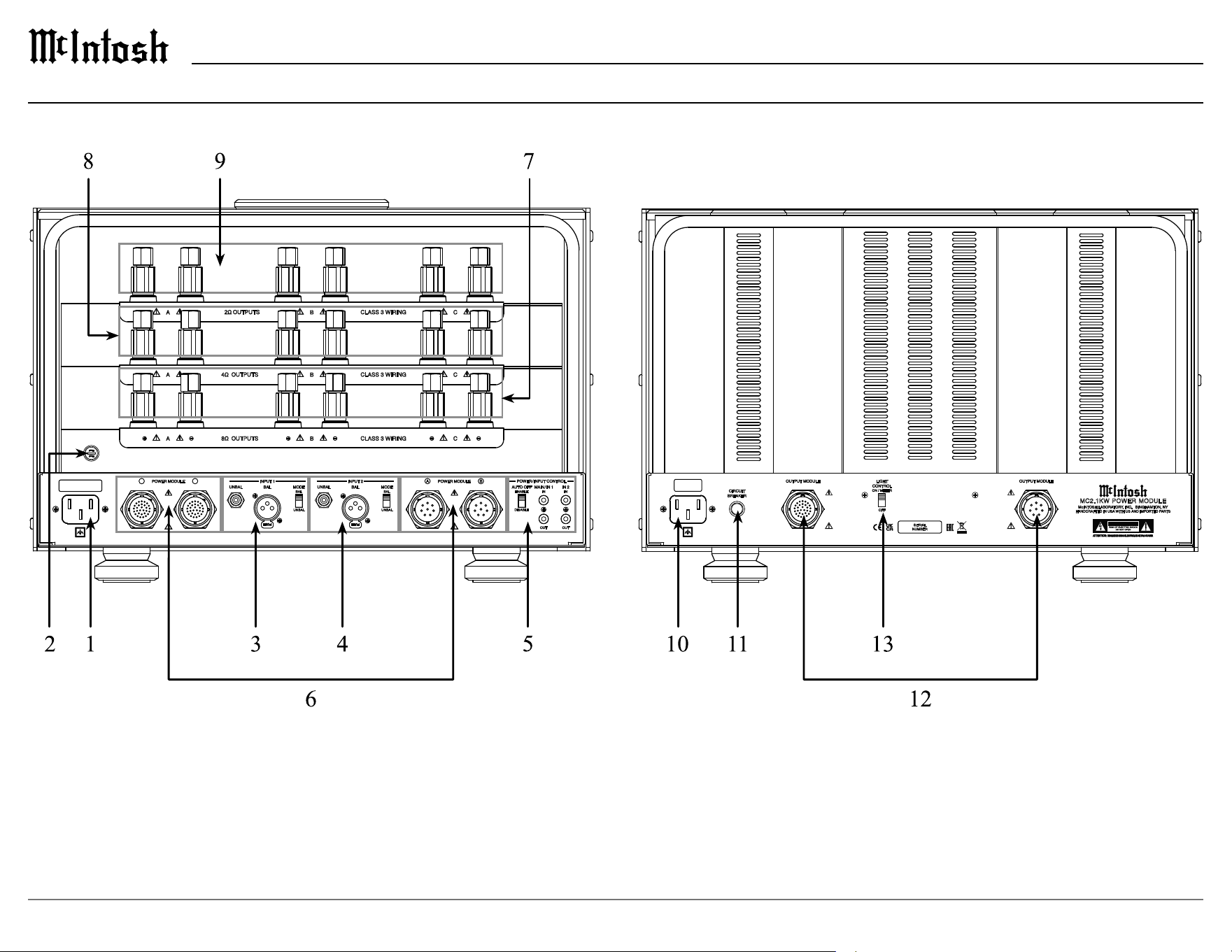
1. Output Module AC Input
Connect the MC2.1KW Output Module to an AC
ci
rcuit that is separate from any MC2.1KW Power
Module. The Output Module can be connected to
an AC circuit with another Output Module or other
lower power system components.
2. Fuse
Under normal operation, the fuse should not need
to b
e replaced. If required, refer to the rear panel
for the proper fuse type and rating.
3. INPUT 1
UNBAL – This input accepts an unbalanced (RCA)
s
i
gnal from a preamplier.
BAL – This input accepts a balanced (XLR) signal
f
ro
m a preamplier.
MODE – Set the MODE switch to the appropriate
p
os
ition depending on the type of input being used.
Only one type of input (UNBAL or BAL) should
b
e c
onnected to INPUT 1.
Refer to pages 14 and 15 for additional information
o
n
connecting inputs.
4. INPUT 2
UNBAL – This input accepts an unbalanced (RCA)
si
gnal from a preamplier.
BAL – This input accepts a balanced (XLR) signal
f
ro
m a preamplier.
MODE – Set the MODE switch to the appropriate
p
os
ition depending on the type of input being used.
Only one type of input (UNBAL or BAL) should
b
e c
onnected to INPUT 2. Refer to pages 14 and 15
for additional information on connecting inputs.
5. POWER/INPUT CONTROL
AUTO OFF – When enabled, after approximately
3
0 m
ins without an audio signal, the MC2.1KW
will turn o to conserve power. The AUTO OFF
switch can be set to DISABLE to prevent this.
If the front panel POWER Control Knob is set
to OFF/REMOTE and the MC2.1KW is being
controlled by a preamplier, the AUTO OFF
function is automatically disabled.
MAIN/IN 1 - When connected to a preamplier
w
i
th power control capabilities, a control signal at
the IN connection will turn the MC2.1KW on and
select INPUT 1. The OUT connection provides a
power control signal that can be used to control
other components. The OUT connection is always
active whenever the MC2.1KW is powered on,
regardless of a signal at the IN connection.
IN 2 -When connected to a preamplier with
po
wer control capabilities, a control signal at the
IN connection will turn the MC2.1KW on and
select INPUT 2. The OUT connection provides a
power control signal that can be used to control
other components. The OUT connection is active
whenever INPUT 2 is selected.
To use POWER/INPUT CONTROL the front
pa
n
el POWER Control Knob must be in the OFF/
REMOTE position. If the POWER Control Knob
is set to INPUT 1 or INPUT 2, all power control
signals are overridden.
If there is a control signal present at both MAIN/
I
N
1 and IN2 at the same time, INPUT 2 will be
selected. To switch back to INPUT 1, the control
signal on IN2 must be turned o.
6. POWER MODULE Connections
These connections are used to connect the
MC
2.1KW Output Module to each of the 2
MC2.1KW Power Modules using the supplied
interconnect cables.
Refer to pages 12 and 13 for additional information
on
connecting the modules.
7. 8Ω OUTPUTS
This set of outputs is for connecting an 8Ω
lo
udspeaker to the MC2.1KW. Multiple pairs of
outputs (A, B and C) are provided for bi-wiring or
tri-wiring.
Refer to pages 16 and 17 for additional information
on c
onnecting loudspeakers.
8. 4Ω OUTPUTS
This set of outputs is for connecting a 4Ω
loudspeaker to the MC2.1KW. Multiple pairs of
outputs (A, B and C) are provided for bi-wiring or
tri-wiring.
Refer to pages 16 and 17 for additional information
on c
onnecting loudspeakers.
9. 2Ω OUTPUTS
This set of outputs is for connecting a 2Ω
lo
udspeaker to the MC2.1KW. Multiple pairs of
outputs (A, B and C) are provided for bi-wiring or
tri-wiring.
Refer to pages 16 and 17 for additional information
on c
onnecting loudspeakers.
10. Power Module AC Input
Connect the MC2.1KW Power Module to an AC
ci
rcuit that is separate from any other MC2.1KW
Power Module or any other system component.
11. CIRCUIT BREAKER
Under normal operation, the CIRCUIT BREAKER
s
h
ould never activate. If the breaker does activate,
the tip of the breaker will pop out. Reset the
breaker by pushing in on the tip.
12. OUTPUT MODULE Connections
These connections are used to connect each of the 2
MC2.1KW Power Modules to the MC2.1KW Output
Module using the supplied interconnect cables.
Refer to pages 12 and 13 for additional information
on
connecting the modules.
13. LIGHT CONTROL Switch
This switch is used to control the illumination of
the front panel capacitor bank. When set to ON/
METER, the capacitor bank illumination will follow
the illumination of the power output meter. When
set to OFF, the illumination will always be o.
Refer to pages 8 and 9 for controlling illumination
of t
he meter and capacitor bank.
12
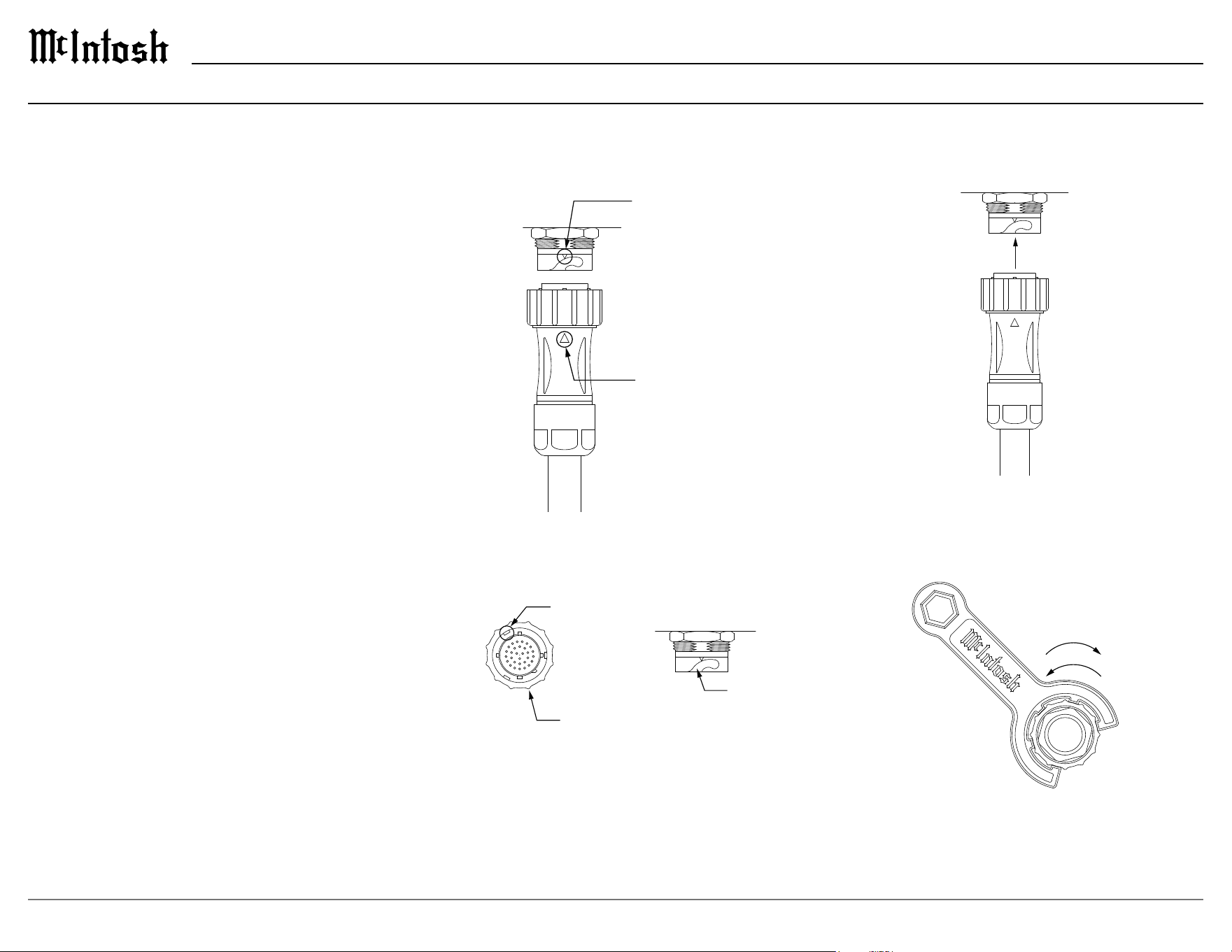
Inserting and Locking the Cables
1. Align the indicator on the cable connector with
the indicator on the receptacle.
2. Rotate the locking ring on the cable connector
so that one of the three locking keys engages the
key slot.
3. Gently insert the cable
connector into the receptacle.
4.
Rotate the locking ring clockwise until the
connector is fully locked into the receptacle. The
supplied McIntosh wrench can be used to assist
in locking the connectors.
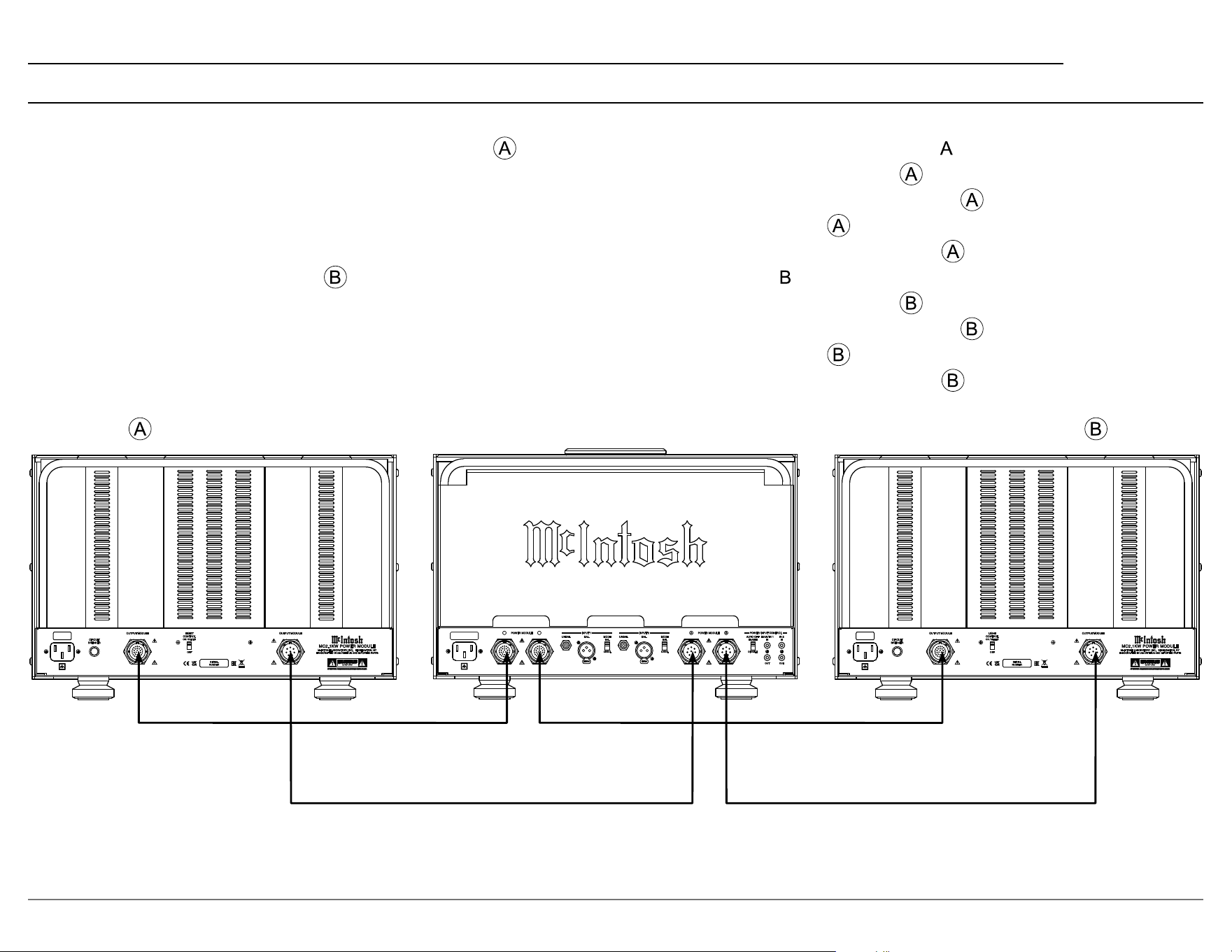
Connecting the Modules
Each MC2.1KW Power Module must be properly
connected to the MC2.1KW Output Module for the
system to operate. Two 30 Pin Interconnect Cables
with green ID rings and two 8 Pin Interconnect
Cables with blue ID rings are provided for these
connections. If any of the four cables are not
connected, or if any are not connected to the
correct module, the OFF/REMOTE indicator on
the front panel of the MC2.1KW Output Module
will not illuminate and the system will not power
on. Follow the steps below on how to insert and
lock the connectors and follow the steps on page 13
to connect the modules together.
ALIGNMENT
INDICATOR
ALIGNMENT
INDICATOR
LOCK
UNLOCK
LOCKING KEY
LOCKING
RING
KEY
SLOT
ALIGNMENT
INDICATOR
ALIGNMENT
INDICATOR
LOCK
UNLOCK
LOCKING KEY
LOCKING
RING
KEY
SLOT
ALIGNMENT
INDICATOR
ALIGNMENT
INDICATOR
LOCK
UNLOCK
LOCKING KEY
LOCKING
RING
KEY
SLOT
ALIGNMENT
INDICATOR
ALIGNMENT
INDICATOR
LOCK
UNLOCK
LOCKING KEY
LOCKING
RING
KEY
SLOT
ALIGNMENT
INDICATOR
ALIGNMENT
INDICATOR
LOCK
UNLOCK
LOCKING KEY
LOCKING
RING
KEY
SLOT
ALIGNMENT
INDICATOR
ALIGNMENT
INDICATOR
LOCK
UNLOCK
LOCKING KEY
LOCKING
RING
KEY
SLOT
13
MC2.1KW
OUTPUT MODULE OUTPUT MODULE
CIRCUIT
BREAKER
McINTOSH LABORATORY, INC. BINGHAMTON, NY
HANDCRAFTED IN USA WITH US AND IMPORTED PARTS
MC2 .1KW POWE R MODU LE
SERIAL
NUMBER
CCAAUUTTIIOONN
OFF
ON / METER
LIGHT
CONTROL
OUTPUT MODULE OUTPUT MODULE
CIRCUIT
BREAKER
McINTOSH LABORATORY, INC. BINGHAMTON, NY
HANDCRAFTED IN USA WITH US AND IMPORTED PARTS
MC2 .1KW POWE R MODU LE
SERIAL
NUMBER
CCAAUUTTIIOONN
OFF
ON / METER
LIGHT
CONTROL
PUSH
PUSH
UNBAL
BAL
MODE
INPUT 1
BAL
UNBAL
POWER MODULE
A B
UNBAL
BAL
MODE
INPUT 2
BAL
UNBAL
DISABLE
ENABLE
AUTO OFF
IN
MAIN / IN 1
IN
IN 2
OUT OUT
POWER MODULE
A B
POWER / INPUT CONTROL
Connecting the Modules (continued)
Power Module Output Module Power Module
30 Conductor Cable (Green Ring)
8 Conductor Cable (Blue Ring)
Connecting the Cables
1. Choose one of the two MC2.1KW Power Modules to be the Module. For convenience, use the Power Module with an in the serial number.
2. Connect one 30 Pin Interconnect Cable (Green Ring) ring to the 30 Pin Receptacle (Green Ring) on the back of the
Power Module rear panel.
3. Connect this same cable to the 30 Pin Receptacle (Green Ring) on the back of the MC2.1KW Output Module that is labeled
.
4. Connect one 8 Pin Interconnect Cable (Blue Ring) to the 8 Pin Receptacle (Blue Ring) on the back of the
Power Module rear panel.
5. Connect this same cable to the 8 Pin Receptacle (Blue Ring) on the back of the MC2.1KW Output Module that is labeled
.
6. The other Power Module will be the
Module. For convenience, this is the Power Module with a in the serial number.
7. Connect one 30 Pin Interconnect Cable (Green Ring) ring to the 30 Pin Receptacle (Green Ring) on the back of the
Power Module rear panel.
8. Connect this same cable to the 30 Pin Receptacle (Green Ring) on the back of the MC2.1KW Output Module that is labeled
.
9. Connect one 8 Pin Interconnect Cable (Blue Ring) to the 8 Pin Receptacle (Blue Ring) on the back of the
Power Module rear panel.
10. Connect this same cable to the 8 Pin Receptacle (Blue Ring) on the back of the MC2.1KW Output Module that is labeled
.
14
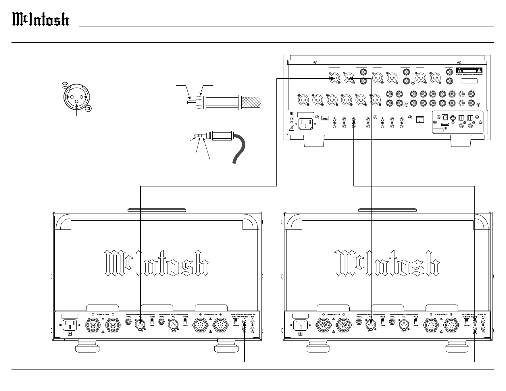
Connecting a Single Preamplier
XLR Connectors
Meter
Illumination
Control
Power
Control
Ground
Signal Ground
RCA Connectors
Power Control Connectors
PIN 1PIN 2
PIN 3
(+) Signal Ground
(-) Signal
2
1
3
HDMI (ARC)
USB AUDIO
COAX 2
COAX 1
MCT OPTICAL 2 OPTICAL 1
DIGITAL AUDIO INPUTS
SERIAL
NUMBER
MAIN
TRIG 1
TRIG 3
PASSTHRU
TRIG 2
TRIG 4
IR IN
RS232
EXTERNAL CONTROL DATA PORTS
5
3
1
6
4
2
SERVICE
PORT
NETWORK
CONTROL / UPDATE
ONLY
POWER CONTROL
L
R
BAL R BAL L BAL R BAL L
L
R
BAL R BAL L
L
R
MAIN / HIGH PASS OUTPUT 1 / LOW PASS
OUTPUT 2 (SUBWOOFER)
UNBAL UNBAL UNBAL
SERIAL
NUMBER
CAUTION
RISK OF ELECTRIC SHOCK
DO NOT OPEN
2
GND
L
R
1 42
3
1
L
R
BALANCED INPUTS PROCESSOR LOOP
SEND
UNBALANCED INPUTS
PHONO INPUTS
1R 1L 2R 2L 3R 3L
RETURN
PUSH
PUSH
UNBAL
BAL
MODE
INPUT 1
BAL
UNBAL
POWER MODULE
A B
UNBAL
BAL
MODE
INPUT 2
BAL
UNBAL
DISABLE
ENABLE
AUTO OFF
IN
MAIN / IN 1
IN
IN 2
OUT OUT
POWER MODULE
A B
POWER / INPUT CONTROL
PUSH
PUSH
UNBAL
BAL
MODE
INPUT 1
BAL
UNBAL
POWER MODULE
A B
UNBAL
BAL
MODE
INPUT 2
BAL
UNBAL
DISABLE
ENABLE
AUTO OFF
IN
MAIN / IN 1
IN
IN 2
OUT OUT
POWER MODULE
A B
POWER / INPUT CONTROL
When connecting a preamplier to the MC2.1KW use connectors with the pin
congurations shown below.
PREAMPLIFIER
RIGHT OUTPUT MODULE LEFT OUTPUT MODULE
15
MC2.1KW
HDMI (ARC)
USB AUDIO
COAX 2
COAX 1
MCT OPTICAL 2 OPTICAL 1
DIGITAL AUDIO INPUTS
SERIAL
NUMBER
MAIN
TRIG 1
TRIG 3
PASSTHRU
TRIG 2
TRIG 4
IR IN
RS232
EXTERNAL CONTROL DATA PORTS
5
3
1
6
4
2
SERVICE
PORT
NETWORK
CONTROL / UPDATE
ONLY
POWER CONTROL
L
R
BAL R BAL L BAL R BAL L
L
R
BAL R BAL L
L
R
MAIN / HIGH PASS OUTPUT 1 / LOW PASS
OUTPUT 2 (SUBWOOFER)
UNBAL UNBAL UNBAL
SERIAL
NUMBER
CAUTION
RISK OF ELECTRIC SHOCK
DO NOT OPEN
2
GND
L
R
1 42
3
1
L
R
BALANCED INPUTS PROCESSOR LOOP
SEND
UNBALANCED INPUTS
PHONO INPUTS
1R 1L 2R 2L 3R 3L
RETURN
MAIN
TRIG 1
TRIG 3
PASSTHRU
TRIG 2
TRIG 4
IR IN
RS232
EXTERNAL CONTROL DATA PORTS
5
3
1
6
4
2
SERVICE
PORT
NETWORK
CONTROL / UPDATE
ONLY
POWER CONTROL
2
GND
L
R
BAL R BAL L BAL R BAL L
L
R
BAL R BAL L
L
R
L
R
1 42
3
1
L
R
UNBAL UNBAL UNBAL
SERIAL
NUMBER
BALANCED INPUTS PROCESSOR LOOP
MAIN / HIGH PASS OUTPUT 1 / LOW PASS
OUTPUT 2 (SUBWOOFER)
UNBALANCED INPUTS
PHONO INPUTS
1R 1L 2R 2L 3R 3L
CAUTION
RISK OF ELECTRIC SHOCK
DO NOT OPEN
SEND
RETURN
HDMI (ARC)
USB AUDIO
COAX 2
COAX 1
MCT OPTICAL 2 OPTICAL 1
DIGITAL AUDIO INPUTS
SERIAL
NUMBER
PUSH
PUSH
UNBAL
BAL
MODE
INPUT 1
BAL
UNBAL
POWER MODULE
A B
UNBAL
BAL
MODE
INPUT 2
BAL
UNBAL
DISABLE
ENABLE
AUTO OFF
IN
MAIN / IN 1
IN
IN 2
OUT OUT
POWER MODULE
A B
POWER / INPUT CONTROL
PUSH
PUSH
UNBAL
BAL
MODE
INPUT 1
BAL
UNBAL
POWER MODULE
A B
UNBAL
BAL
MODE
INPUT 2
BAL
UNBAL
DISABLE
ENABLE
AUTO OFF
IN
MAIN / IN 1
IN
IN 2
OUT OUT
POWER MODULE
A B
POWER / INPUT CONTROL
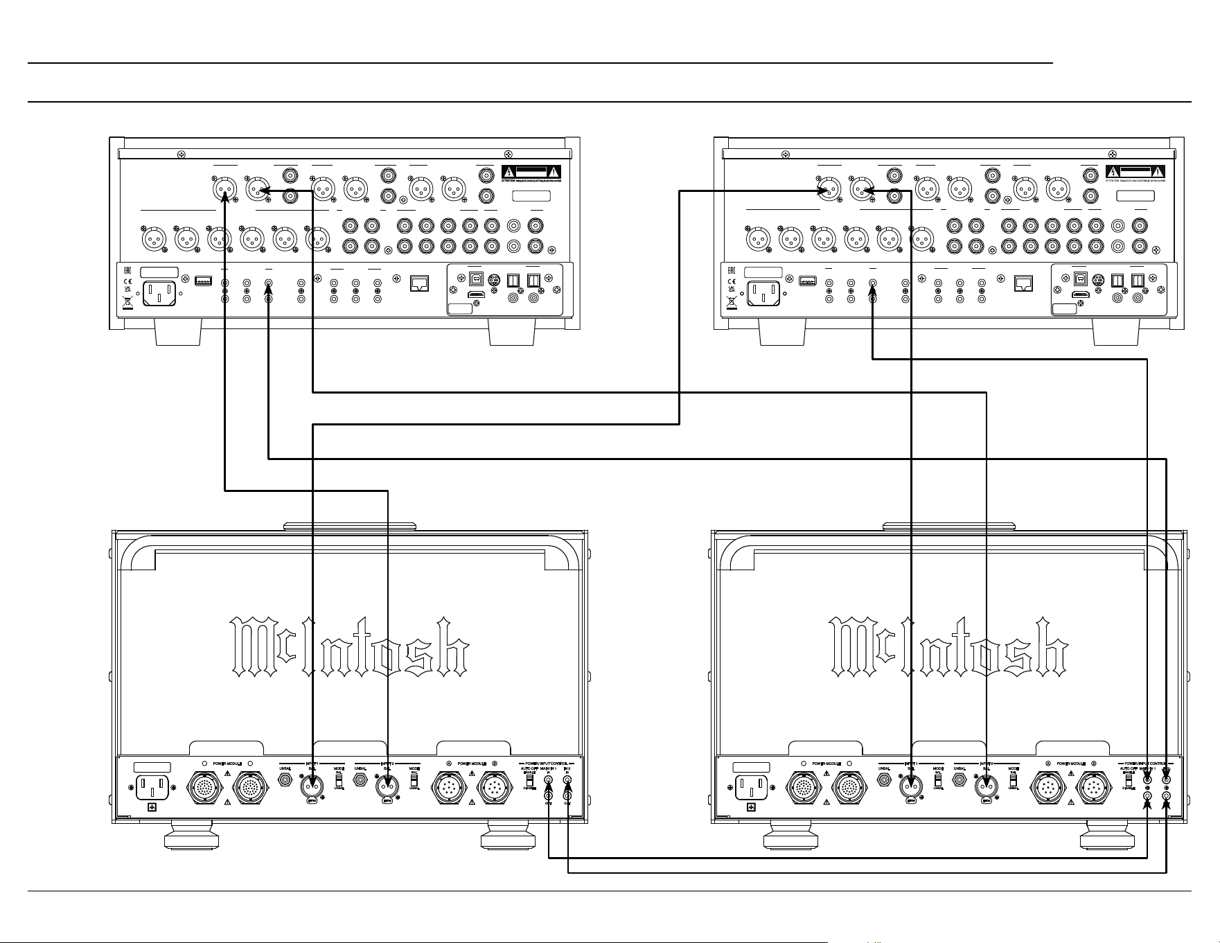
Connecting Two Preampliers
PREAMPLIFIER 2 PREAMPLIFIER 1
RIGHT OUTPUT MODULE LEFT OUTPUT MODULE
16
Loudspeaker Impedance
The MC2.1KW has three sets of output terminals,
±2 ohm, ±4 ohm, and ±8 ohm. Based on the
specications of your loudspeaker, determine the
best set of terminals to use. For a speaker whose
impedance falls between two choices, use the
lower impedance terminal. Each impedance set has
three pairs of terminals for bi-wiring or tri-wiring
a loudspeaker.
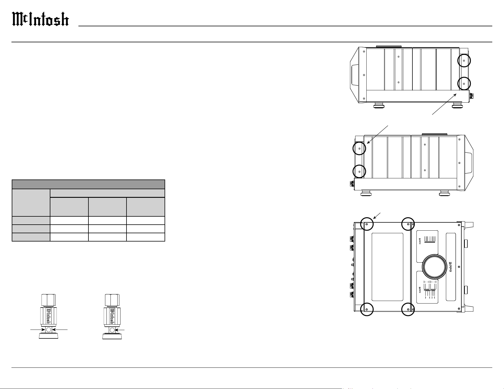
Loudspeaker Cables
When connecting loudspeakers to the MC2.1KW
it is very important to use cables of adequate size.
The size is specied in AWG (American Wire
Gauge). The smaller the gauge number, the larger
the wire size.
Loudspeaker Cable Wire Gauge Guide
Loudspeaker
Impedance
Cable Distance
25 feet
(7.62 meters)
or less
50 feet
(15.24 meters)
or less
100 feet
(30.48 meters)
or less
2 ohms 12AWG 10AWG 8AWG
4 ohms 14AWG 12AWG 10AWG
8 ohms 16AWG 14AWG 12AWG
Connecting a Loudspeaker
BLU
BLU
GRN
Control
RED
RED
YEL
Low
Level
Audio
GRN
VIO
WHT
PRI 2
BLU
GRY
BLK
PRI 1
SEC 1
SEC 2
R-CORE POWER TRANSFORMER
Frequency Range
15Hz to 100kHz
GRY
ORN
RED
BLU
VIO
GRN
WHT
YEL
8Ω
+
+
+
+
IN
4Ω
2Ω
8Ω
-
-
-
-
IN
4Ω
2Ω
COM
BLK
BALANCED AUDIO AUTOFORMER
Power Level
2kW
MC2 .1K W OUTP UT MO DULE
FREQUENCY RESPONSE
+0, -0.25dB from 20Hz to 20,000Hz
+0, -3dB from 10Hz to 100,000Hz
A-WEIGHTED SIGNAL TO NOISE RATIO
123dB below rated output
INPUT SENSITIVITY
2.5 volts unbalanced
5.0 volts balanced
TOTAL HARMONIC DISTORTION
0.005% maximum harmonic distortion at
any level from 250 mW to rated power output
POWER OUTPUT
2000 watts into an 8, 4 or 2 ohm load is the
minimum sine wave continuous average
pow e r output
DYNAMIC HEADROOM
2.5dB
1/8 in Hex T-Handle
5/32 in Hex T-Handle
1
2
3
4
1 2
3 4
Output Terminals
Loudspeaker cables should be terminated on the
ends to securely t into the terminals according to
the dimensions below.
5/16”
7.9 mm
3/16”
4.8 mm
Ø
Output Terminal Covers
To gain access to the output terminals, use the
supplied 1/8 in Hex T-Handle to remove the four
screws that hold the clear polycarbonate cover to
the rear of the output module. If needed, the top
cover with glass window may also be removed by
using the supplied 5/32 in Hex T-Handle to remove
the four screws that hold the cover to the top. After
all loudspeaker connections have been made, all
terminal covers must be reinstalled with their
appropriate screws.
17
MC2.1KW
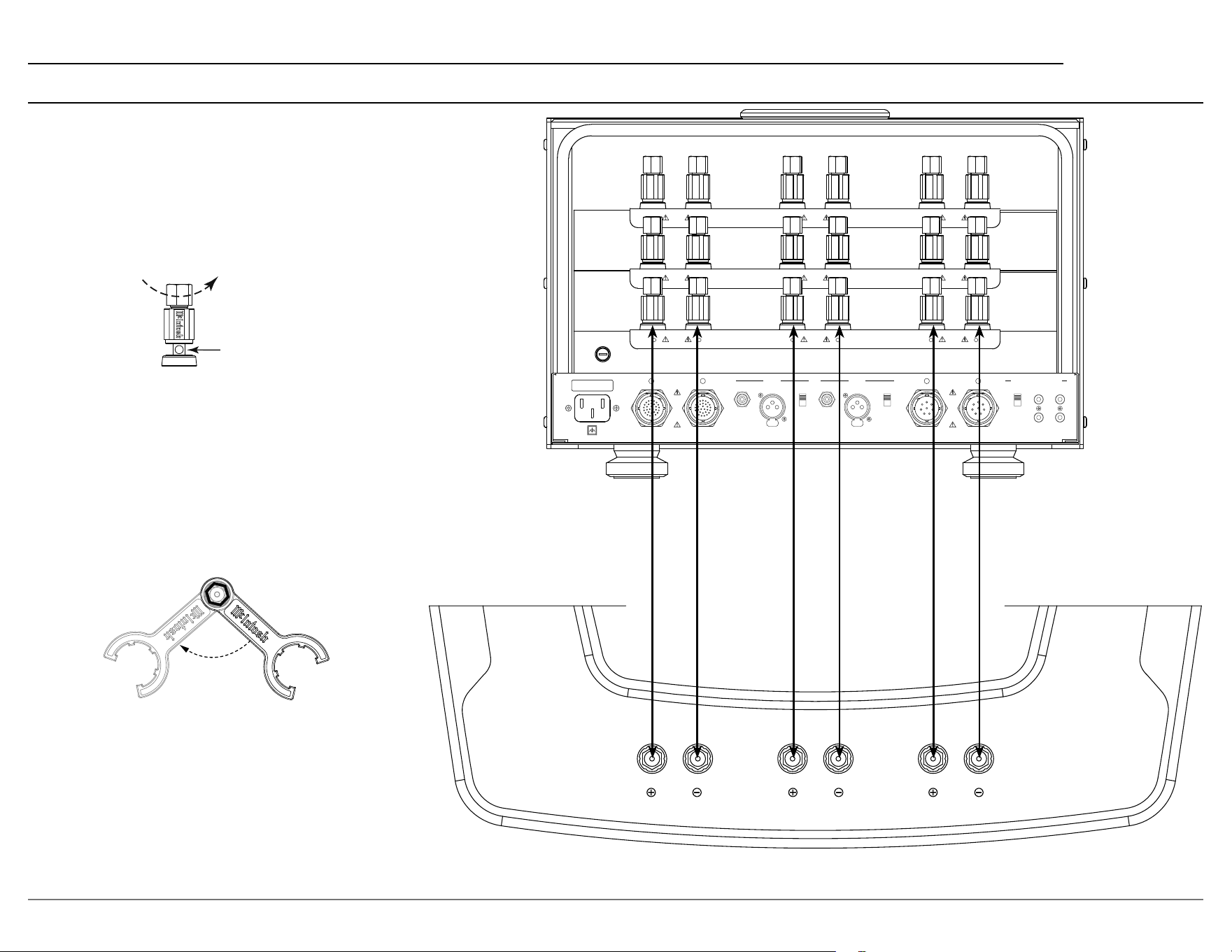
Loudspeaker Cable Connections
When connecting loudspeaker cables to the
MC2.1KW output terminals follow the steps
below:
1. Make sure AC power is disconnected.
2. Rotate the top of the output terminal counter-
clockwise until an opening appears.
Opening
3. Insert the loudspeaker cable into the output
terminal. Proper polarity must be maintained
for all connections. (+/-)
4. Rotate the top of the output terminal clockwise
until it is nger tight.
5. Place the McIntosh wrench over the top of the
output terminal and rotate the output terminal
clockwise one quarter of a turn (90°). Do not
over tighten.
FUSE
FUSE
PUSH
PUSH
UNBAL
BAL
MODE
INPUT 1
BAL
UNBAL
POWER MODULE
A B
UNBAL
BAL
MODE
INPUT 2
BAL
UNBAL
DISABLE
ENABLE
AUTO OFF
IN
MAIN / IN 1
IN
IN 2
OUT OUT
POWER MODULE
A B
POWER / INPUT CONTROL
A
B
CLASS 3 WIRING
C
A
B
C
A
+
-
B
+
-
C
+
-
CLASS 3 WIRING
CLASS 3 WIRING
2Ω
OUTPUTS
4Ω
OUTPUTS
8Ω
OUTPUTS
HIGHMIDLOW
Connecting a Loudspeaker (continued)

18
Power Module Specications
Power Requirements
100 Volts, 50/60Hz at 1440 watts
110 Volts, 50/60Hz at 13.0 amps
120 Volts, 50/60Hz at 12.0 amps
220 Volts, 50/60Hz at 7.5 amps
230 Volts, 50/60Hz at 6.5 amps
240 Volts, 50/60Hz at 6.5 amps
Refer to the rear panel of the MC2.1KW Power
Module for the correct voltage.
Overall Dimensions
Width is 17 15/16 inches (45.6cm)
Height is 11 7/8 inches (30.2cm)
Depth is 30 3/16 inches (76.7cm)
Weight
145 pounds (65.8 kg) net
165 pounds (74.8 kg) in shipping carton
System Specications
Output Module Specications
Power Requirements
100 Volts, 50/60Hz at 35 watts
110 Volts, 50/60Hz at 35 watts
120 Volts, 50/60Hz at 35 watts
220 Volts, 50/60Hz at 35 watts
230 Volts, 50/60Hz at 35 watts
240 Volts, 50/60Hz at 35 watts
Refer to the rear panel of the MC2.1KW Output
Module for the correct voltage.
Overall Dimensions
Width is 17 15/16 inches (45.6cm)
Height is 12 5/32 inches (30.9cm)
Depth is 30 3/16 inches (76.7cm)
Weight
125 pounds (56.7 kg) net
150 pounds (68 kg) in shipping carton
Power Output
2000 watts into 2 ohm load
2000 watts into 4 ohm load
2000 watts into 8 ohm load
Rated Power Band
20Hz to 20,000Hz
Dynamic Headroom
2.1dB
Wide Band Damping Factor
Greater than 40
Frequency Response
+0, -0.25dB from 20Hz to 20,000Hz
+0, -3dB from 10Hz to 100,000Hz
Total Harmonic Distortion
0.005% maximum harmonic distortion at any power
level from 250 milliwatts to rated power, 20Hz to
20,000Hz
Intermodulation Distortion
0.005% maximum, if the instantaneous peak power
output does not exceed twice the rated power output
for any combination of frequencies from 20Hz to
20,000Hz
Signal To Noise Ratio (A Weighted)
123dB below rated output
Input Sensitivity (for rated output)
5.0 Volts Balanced
2.5 Volts Unbalanced
Input Impedance
22,000 ohms Balanced
22,000 ohms Unbalanced
Voltage Output
126.5V across 8 ohms
89.5V across 4 ohms
63.3V across 2 ohms
Voltage Gain
34dB, 8 ohms
31dB, 4 ohms
28dB, 2 ohms
Power Control Input
5-12VDC
Power Control Output
12VDC, 25mA
19
MC2.1KW
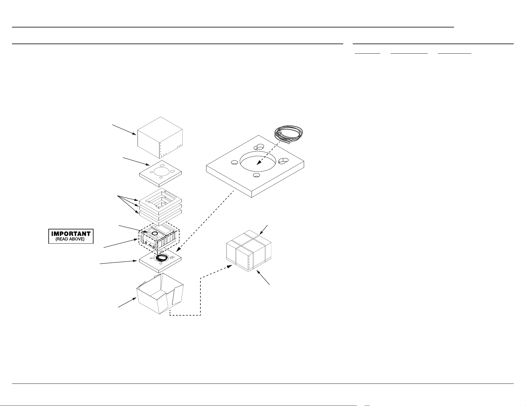
Packing Instructions Parts List
Quantity Part Number Description
1 03410500 Shipping Carton Top
2 03473400 Foam Pads Top/Bottom
3 03467800 Foam Rings
1 03373900 Poly Bag
1 03410400 Shipping Carton Bottom
In the event it is necessary to repack the equip-
ment for shipment, the equipment must be packed
ex
actly as shown below. It is very important
that the four aluminum feet are attached to the
bottom of the equipment. This will ensure the
proper equipment location on the bottom pad.
Failure to do this will result in shipping damage.
Use the original shipping carton and interior parts
only if they are all in good serviceable condition.
If a shipping carton or any of the interior part(s)
are needed, please call or write Customer Service
Department of McIntosh Laboratory. Refer to
page 2. Please see the Part List for the correct part
numbers.
Trademarks of McIntosh Laboratory, Inc.:
The following are Registered Trademarks of McIntosh Laboratory, Inc. in multiple jurisdictions around the world: the written McIntosh logo; the McIntosh Globe logo; the Mc logo; Power Guard; Power Guard
Screen Grid Sensor; Power Guard SGS; LD/HP; Dynamic Power Manager; the 4DPM8 logo; HXD; the HXD logo; Behind The Sound; Legendary Performance.
The following are Trademarks of McIntosh Laboratory, Inc. in multiple jurisdictions around the world: Autoformer; Sentry Monitor; Solid Cinch; McIntosh Monogrammed Heatsinks; Hybrid Drive; DualView;
TripleView; Made of Sound.
The foregoing trademarks, registered and otherwise, are not to be used, reproduced, or registered in any way without the express written permission of McIntosh Laboratory, Inc.
CABLES
USE BANDING
STRAPS AS
SHOWN
SEAL WITH
PACKAGING
TAPE
TOP
CARTON
TOP FOAM PAD
WITH ROUND PLUG
FOAM RING (3X)
UNIT WITH
(4) FEET ON
BOTTOM COVER
POLY BAG
BOTTOM FOAM PAD
CARTON BOTTOM
• FOR OUTPUT MODULE
USE POCKET FOR CABLES.
• FOR POWER MODULE
USE POCKET WITH ROUND PLUG.

© 2024 McIntosh Laboratory, Inc.
McIntosh Part No. 24123700
The continuous improvement of its products is the
policy of McIntosh Laboratory, Inc. who reserve the
right to improve design without notice.
Printed in the U.S.A.
McIntosh Laboratory, Inc.
2 Chambers Street
Binghamton, NY 13903
www.mcintoshlabs.com
