
1
2
3
4
5
2
1
57
9
22
24
19(2x)
11a
10
12
61
24
51
10
42
28(4x)
63
59
27
34
35
49
58
44
45
62
27 34
35 36
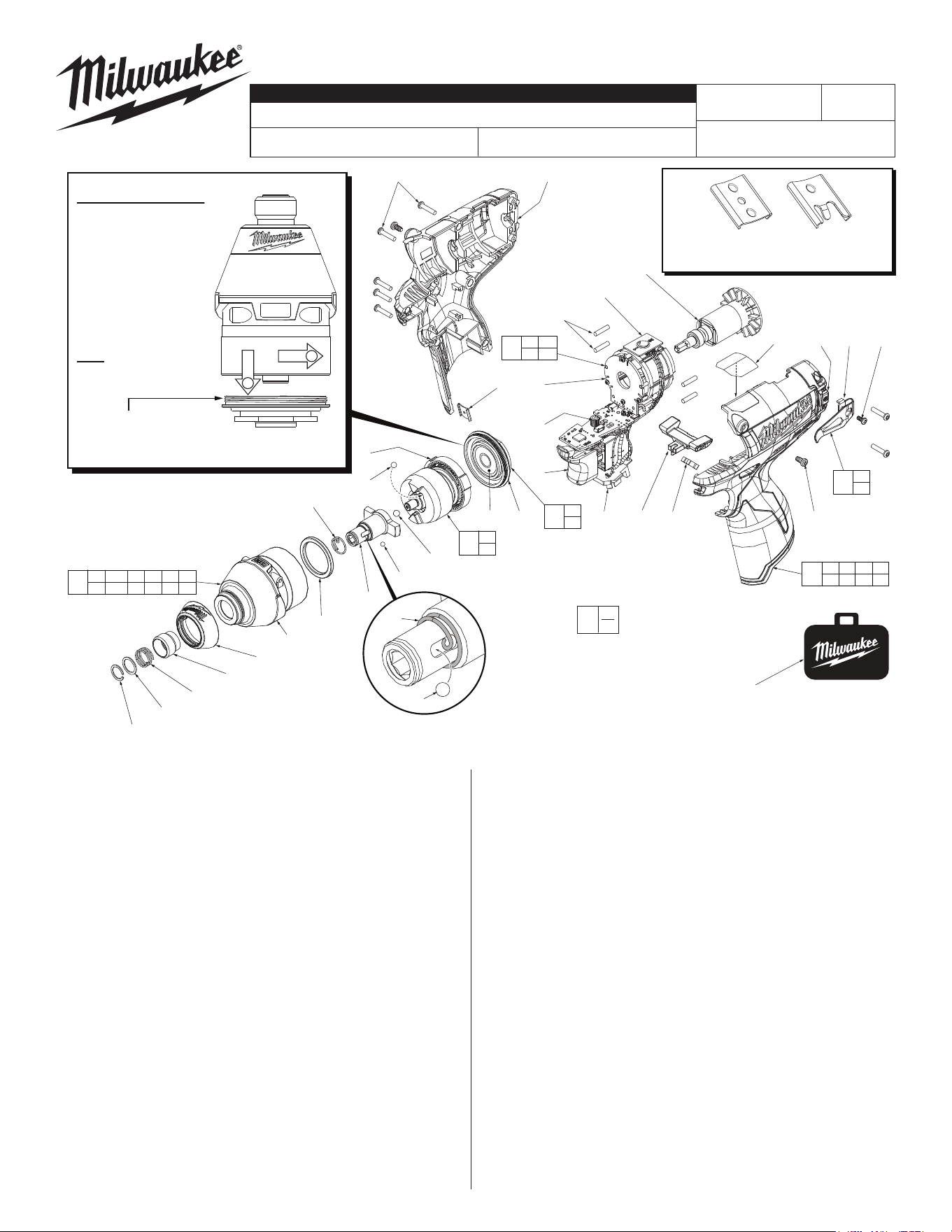
Torque to 260 in/lbs ±24 in/lbs
(300 kgf-cm ±27 kgf-cm)
56
2 3 4 5 6 9
10 11a 25 51 57
25
22
23
36
23
60
28 43 46 47
48 50 64
64 43 44 45
*
IMPORTANT NOTE: Gearcase end cap #25 is
LEFT HAND THREAD!
As an aid to assembly,
carefully lower the complete
front end of tool (gearcase /
impacting system) onto the
gearcase end cap. Gently
hand tighten front end
assembly onto gearcase
end cap. Be careful not
to cross-thread! Once
installed by hand, seat
gearcase end cap with a
good adjustable wrench
using light pressure.
Do not over tighten!
LEFT HAND THREAD
NOTE: Place anvil
spring (51) onto
anvil (11a) with
curled end
inserted in
slot of anvil
as shown.
Place ball (10)
in anvil slot in
front of spring.
51
50(7x)
47
46(2x)
37 38
NOTE: Components of the impacting
assembly (61) can drop out of the
gearcase (57). Care must be taken
to hold those elements in place
when assembling onto the
gearcase end cap (25).
MILWAUKEE TOOL
l
www.milwaukeetool.com
13135 W. LISBON RD., BROOKFIELD, WI 53005
Drwg. 3
BULLETIN NO.
54-26-2481
SERVICE PARTS LIST
FIG. PART NO. DESCRIPTION OF PART NO. REQ.
1 31-12-0575 Rubber Cap (1)
2 45-22-2653 Sleeve (1)
3 34-60-0725 Retaining Ring (1)
4 45-88-1881 Washer (1)
5 40-50-1470 Spring (1)
6 --------------- Anvil Bushing (Not Shown) (1)
9 45-88-2135 Plastic Washer (1)
10 02-02-0170 3.5mm Steel Ball (1)
11a 42-06-0720 1/4" Hex Anvil (1)
12 02-02-1300 5mm Steel Ball (1)
19 02-02-0180 4.7mm Steel Ball (2)
22 --------------- Ball Bearing (1)
23 --------------- Gearcase End Cap (1)
24 --------------- Ring Gear (1)
25 44-66-1065 Gearcase End Cap Assembly (1)
27 --------------- Stator Assembly (1)
28 45-30-0300 Rubber Slug (4)
34 --------------- PCBA (1)
35 --------------- On-OSwitch (1)
36 --------------- Terminal Block Assembly (1)
37 45-24-0810 Fwd/Rev Shuttle (1)
38 40-50-1135 Spring (1)
42 42-70-0055 Housing Connection Clip (1)
43 --------------- Left Handle Halve with Fuel Gauge (1)
44 42-70-0580 Belt Clip (1)
45 --------------- Belt Hook Screw (1)
46 06-82-1090 M3 x 7mm Pan Hd. Plastite Screw (2)
CATALOG NO. 2453-20
REVISED BULLETIN
SPECIFY CATALOG NO. AND SERIAL NO. WHEN ORDERING PARTS
M12™ Brushless 1/4" Hex Impact Driver
STARTING
SERIAL NO.
DATE
May 2019
WIRING INSTRUCTION
E51B
EXAMPLE:
Component Parts (Small #)
Are Included When Ordering
The Assembly (Large #).
0
00
SEE PAGE 3
FIG. PART NO. DESCRIPTION OF PART NO. REQ.
47 --------------- Right Handle Halve (1)
48 12-20-2435 Service Nameplate (Not Shown) (1)
49 42-55-1060 Carrying Case (1)
50 06-82-7236 4-20 x 5/8" Pan Hd. Plastite T-10 Scr (7)
51 40-50-0012 Anvil Spring (1)
56 14-30-1170 Gearcase Assembly (1)
57 28-50-0920 Front Gearcase with Bushing (1)
58 42-70-0490 Belt Clip Assembly (1)
59 16-07-0420 Rotor Assembly (1)
60 31-44-2453 Handle Assembly (1)
61 14-30-1200 Impacting Assembly (1)
62 14-20-1520 Electronics Assembly (1)
63 23-66-2455 POP Switch (1)
64 10-20-2845 Spanish/French Warning Label (1)
FIG. LUBRICATION
(Type 'J' Grease, No. 49-08-4220):
10,11a Lightly coat front washer surface of anvil (11a) with grease,
place a dab in the ball slot of anvil.
24,61 Lightly coat the I.D. of the ring gear (24) and the center of
the planet gears of impacting assembly with grease.
57 Coat inside of bushing inside front gearcase with grease.
59 Coat pinion of rotor assembly (59) with grease.
54-26-2480
42-70-0058
Improved
Design
Original
Design
42-70-0055
*
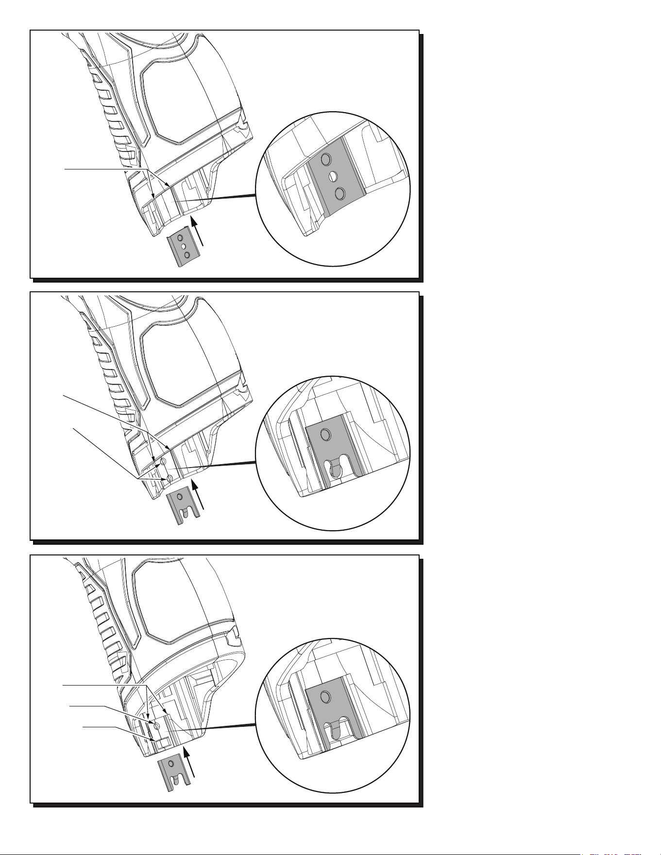
M12™ tools utilize two different Housing
Connection Clip designs depending on the
Handle Set. See page two for details.
42-70-0055
42-70-0058
42-70-0058
Recess in early handle
sets may only have the
slots to accommodate a
housing clip. Use 42-70-0055
only in this situation.
Slots
Recess in newer handle
sets have two slots, a
dimple and a tab cavity to
accommodate the newer
housing clip design.
Slots
Dimple
Tab Cavity
Updated M12™ Handle Sets utilize Housing
Connection Clips No. 42-70-0055 and 42-70-
0058. (The 42-70-0058 is a preferred upgrade).
Install this clip design by aligning the side rails
of the clip with the two slots in the handle set.
Gently push into place with the aid of a small
flat blade screwdriver or a similar instrument.
Be sure that the clip is properly seated in both
slots and that the tab of the clip snaps down in
the round dimpled cavity of the handle set. Be
sure that the clip is flush to sub-flush to the end
of the handle set. To remove the clip, use the
same small flat blade screwdriver or a similar
instrument and lift up on the clip tab while
pushing the clip out of the handle set. Use a
needle nose pliers to gently rebend the clip tab
if necessary. If the tab on the clip is damaged
during this process and is loose or will not stay
in place, replace with a new 42-70-0058 clip.
Early M12™ Handle Sets utilize Housing
Connection Clip No. 42-70-0055. Install this
clip design by aligning the side rails of the clip
with the two slots in the handle set. Gently
push into place with the aid of a small flat
blade screwdriver or a similar instrument. Be
sure that the clip is properly seated in both
slots and that the clip is flush to sub-flush to
the end of the handle set. To remove the clip,
use the same small flat blade screwdriver or a
similar instrument and push the clip out of the
handle set. If the clip is loose or will not stay in
place, a needle nose pliers can be used to
gently bend/pinch the side rails of the clip. If
the clip is damaged do not use, replace with a
new 42-70-0055 housing clip.
Slots
Dimples
Recess in this
handle set design
has slots and dimples
to secure a housing clip.
The 42-70-0055 can be
used but the 42-70-0058 is
preferred in this situation.
Newer M12™ Handle Sets utilize Housing
Connection Clip No. 42-70-0058. Install this
clip design by aligning the side rails of the clip
with the two slots in the handle set. Gently
push into place with the aid of a small flat blade
screwdriver or a similar instrument. Be sure
that the clip is properly seated in both slots and
that the tab of the clip snaps down in the
rectangular cavity of the handle set. Be sure
that the clip is flush to sub-flush to the end of
the handle set. To remove the clip, use the
same small flat blade screwdriver or a similar
instrument and lift the clip tab out of the cavity
while pushing the clip out of the handle set.
Use a needle nose pliers to gently rebend the
clip tab if necessary. If the tab on the clip is
damaged during this process and is loose or
will not stay in place, replace with a new
42-70-0058 clip.
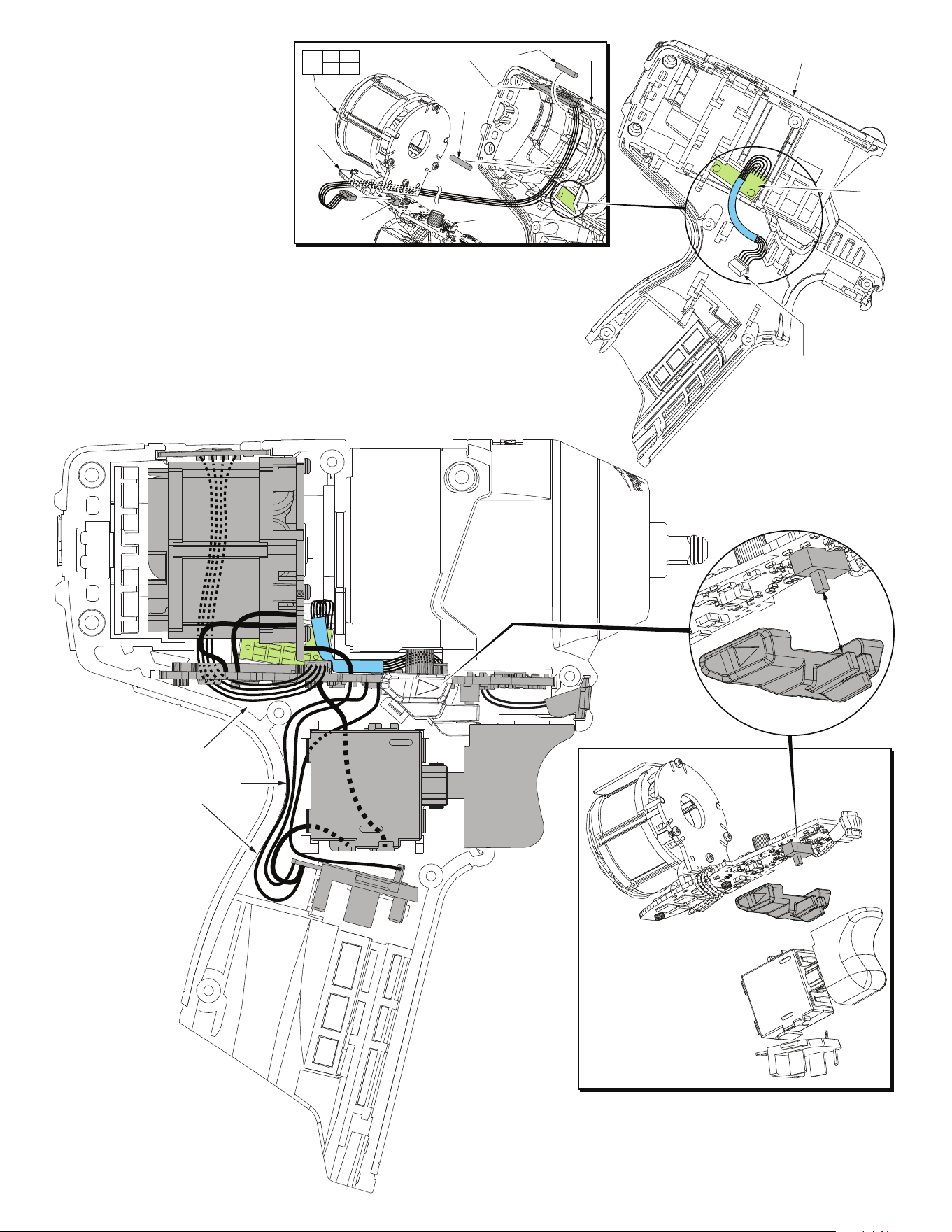
34
43
The fuel gauge assembly is a fixed component of the left
handle halve (43). Connect the five wire terminal block to
the corresponding five wire port on the PCBA.
Place POP Switch (63) into top slot of left handle halve.
Be sure that the ‘2’ is positioned to the back of tool.
Route the four wires through the channel along the
inside wall as shown. Trap the wires in place using
two Rubber Slugs (28). Carefully place all components
of the Electronics Assembly (62) into the handle halve.
Connect the four wire terminal to the port on PCBA (34).
63 28
28
62
27 34
35 36
43
4 wire
port
5 wire
port
5 wire terminal block to
5 wire port on the PCBA
Fuel
Gauge
NOTE:
It is very important to make
sure that wires are tucked down
into the left handle halve to avoid
wires being pinched when
re-assembling tool.
Be sure that all elements of
the Electronics Assembly
(On-Off Switch, PCBA,
LED, Terminal Block
Connector and Stator)
are properly seated into
the left handle halve
before re-assembly.
When installing the Fwd/Rev
Shuttle, be sure to properly
capture the slide button of
the fwd/rev micro switch
on the PCBA with the
front cavity of the shuttle.
Once in the left handle halve,
be careful that no wires
interfer with the travel of the
Fwd/Rev Shuttle.
AS AN AID TO REASSEMBLY,
TAKE NOTICE OF WIRE ROUTING
AND POSITION IN WIRE GUIDES AND
TRAPS WHILE DISMANTLING TOOL.
BE CAREFUL AND AVOID PINCHING
WIRES BETWEEN HANDLE HALVES
WHEN ASSEMBLING.