
1
2
3
7
8 9 10
11 12
2
44
47
38
29 30 40
41 42 43
36
33 34
35
39
30 40 41
42 43
28
10 13 14 15 17 18 20 21
22 23 24 25 26 27 45
*
See
detail
above
MILWAUKEE ELECTRIC TOOL CORPORATION
13135 W. Lisbon Road, Brookfi eld, WI 53005
Drwg. 3
BULLETIN NO.
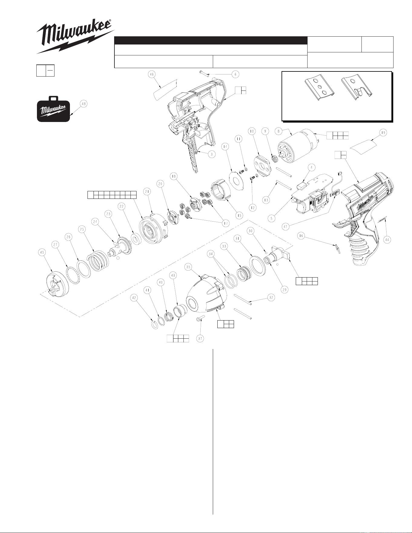
54-26-2450
SERVICE PARTS LIST
FIG. PART NO. DESCRIPTION OF PART NO. REQ.
1 31-50-2402 Handle Set (1)
2 --------------- Left Handle Half (1)
3 --------------- Right Handle Half (1)
4 45-24-0105 Fwd./Rev. Button (1)
5 23-66-1105 Electronics Module Assembly (1)
6 06-82-2385 M2.6 x 14 T-9 Screw (5)
7 23-30-0090 Motor Service Assembly (1)
8 --------------- Motor (1)
9 --------------- Pinion (1)
10 --------------- Motor Mount (1)
11 --------------- Washer (2)
12 --------------- M3 x 6 Screw (2)
13 06-65-0075 Pin (2)
14 --------------- Washer (1)
15 --------------- Ring Gear (1)
16 42-70-0055 Housing Connection Clip (1)
17 --------------- Planet Gear Set (8)
18 --------------- Sun Gear (1)
19 10-20-0790 Warning Label (1)
20 --------------- Carriage (1)
21 --------------- Rear Housing (1)
22 --------------- Ball Bearing (1)
23 --------------- Cam Shaft (1)
24 --------------- 3/16" Dia. Steel Ball (2)
25 --------------- Compression Spring (1)
26 --------------- Washer (1)
CATALOG NO. 2450-20
REVISED BULLETIN
SPECIFY CATALOG NO. AND SERIAL NO. WHEN ORDERING PARTS
M12™ Impact Driver
STARTING
SERIAL NO.
DATE
Feb. 2014
WIRING INSTRUCTION
B59A
EXAMPLE:
Component Parts (Small #)
Are Included When Ordering
The Assembly (Large #).
0
00
SEE PAGE THREE
FIG. PART NO. DESCRIPTION OF PART NO. REQ.
27 --------------- 3.0mm Dia. Steel Ball (29)
28 14-29-0190 Gear Assembly (1)
29 --------------- Anvil (1)
30 --------------- 3.5mm Steel Ball (2)
31 45-88-0455 Washer (1)
32 06-65-0085 Pin (2)
33 --------------- Sleeve Bearing (1)
34 --------------- O-Ring (2)
35 --------------- Gear Housing (1)
36 14-30-0005 Gearcase Assembly (1)
37 06-81-0005 M3.5 x 24 Screw (4)
38 45-22-0015 Sleeve and Anvil Assembly (1)
39 45-22-0010 Sleeve and Ball Assembly (1)
40 --------------- Spring (1)
41 --------------- Washer (1)
42 --------------- Retaining Ring (1)
43 --------------- Sleeve (1)
44 --------------- LED Label (1)
45 --------------- Hammer (1)
46 12-20-2450 Service Nameplate (1)
47 --------------- Fuel Gauge LED Assembly (1)
48 42-55-2450 Carrying Case, Optional (1)
Service replacement Gear Assembly (28)
comes with a motor mount plate that must
be removed and discarded when servicing.
A Motor Mount Plate (10) already exists on
the Motor Assembly (7).
FIG. LUBRICATION
(Type 'J' Grease, No. 49-08-4220):
33 Coat inside grooves of Bushing (33) with grease.
38 Lightly coat front washer surface of Anvil (38) with
grease. Place a dab of grease in the Ball holes
and in the hole in the back of the Anvil.
NOTE: Gear Assembly (28) must be attached
to the Motor Assembly (7) prior to installing in
Gearcase Assembly (36).
NOTE:
Pins (13) are shorter
than Pins (32).
42-70-0058
Improved
Design
Original
Design
42-70-0055
*
M12™ tools utilize two different Housing
Connection Clip designs depending on the
Handle Set . See page two for details.
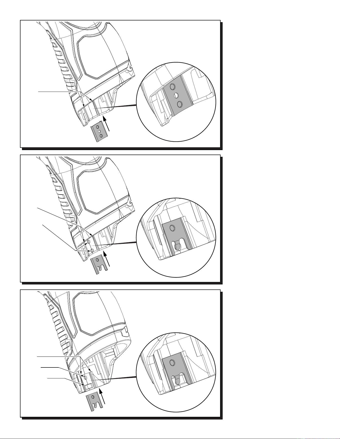
42-70-0055
42-70-0058
42-70-0058
Recess in early handle
sets may only have the
slots to accommodate a
housing clip. Use 42-70-0055
only in this situation.
Slots
Recess in newer handle
sets have two slots, a
dimple and a tab cavity to
accommodate the newer
housing clip design.
Slots
Dimple
Tab Cavity
Updated M12™ Handle Sets utilize Housing
Connection Clips No. 42-70-0055 and 42-70-
0058. (The 42-70-0058 is a preferred upgrade).
Install this clip design by aligning the side rails
of the clip with the two slots in the handle set.
Gently push into place with the aid of a small
flat blade screwdriver or a similar instrument.
Be sure that the clip is properly seated in both
slots and that the tab of the clip snaps down in
the round dimpled cavity of the handle set. Be
sure that the clip is flush to sub-flush to the end
of the handle set. To remove the clip, use the
same small flat blade screwdriver or a similar
instrument and lift up on the clip tab while
pushing the clip out of the handle set. Use a
needle nose pliers to gently rebend the clip tab
if necessary. If the tab on the clip is damaged
during this process and is loose or will not stay
in place, replace with a new 42-70-0058 clip.
Early M12™ Handle Sets utilize Housing
Connection Clip No. 42-70-0055. Install this
clip design by aligning the side rails of the clip
with the two slots in the handle set. Gently
push into place with the aid of a small flat
blade screwdriver or a similar instrument. Be
sure that the clip is properly seated in both
slots and that the clip is flush to sub-flush to
the end of the handle set. To remove the clip,
use the same small flat blade screwdriver or a
similar instrument and push the clip out of the
handle set. If the clip is loose or will not stay in
place, a needle nose pliers can be used to
gently bend/pinch the side rails of the clip. If
the clip is damaged do not use, replace with a
new 42-70-0055 housing clip.
Slots
Dimples
Recess in this
handle set design
has slots and dimples
to secure a housing clip.
The 42-70-0055 can be
used but the 42-70-0058 is
preferred in this situation.
Newer M12™ Handle Sets utilize Housing
Connection Clip No. 42-70-0058. Install this
clip design by aligning the side rails of the clip
with the two slots in the handle set. Gently
push into place with the aid of a small flat blade
screwdriver or a similar instrument. Be sure
that the clip is properly seated in both slots and
that the tab of the clip snaps down in the
rectangular cavity of the handle set. Be sure
that the clip is flush to sub-flush to the end of
the handle set. To remove the clip, use the
same small flat blade screwdriver or a similar
instrument and lift the clip tab out of the cavity
while pushing the clip out of the handle set.
Use a needle nose pliers to gently rebend the
clip tab if necessary. If the tab on the clip is
damaged during this process and is loose or
will not stay in place, replace with a new
42-70-0058 clip.
3
3
2
2
1
1
4
4
8
9
8
7
6
5
5
6
7
10
11
12
13
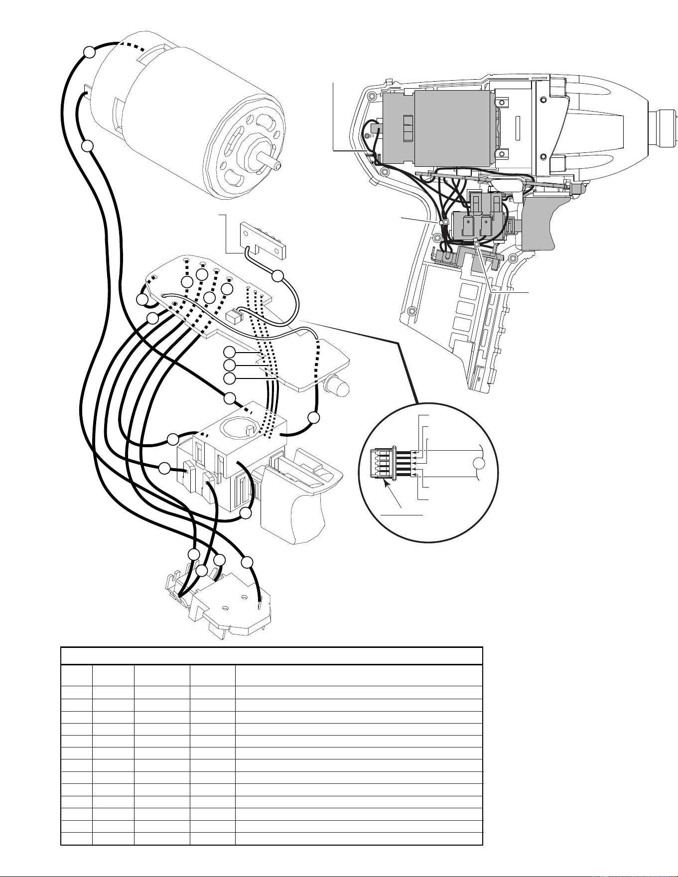
Terminals, Connectors and 1 or 2 End Wire Preparation
Wire
Color
Origin or
Gauge
Wire
No.
Length
WIRING SPECIFICATIONS
1 Black 23-30-0090 ----- Component of the motor assembly.
2 Red 23-30-0090 ----- Component of the motor assembly.
3 White 23-66-1105 ----- Component of the electronics module assembly.
4 Black 23-66-1105 ----- Component of the electronics module assembly.
5 Black 23-66-1105 ----- Component of the electronics module assembly.
6 Red 23-66-1105 ----- Component of the electronics module assembly.
7 White 23-66-1105 ----- Component of the electronics module assembly.
8 Red 23-66-1105 ----- Component of the electronics module assembly.
9 Red 23-66-1105 ----- Component of the electronics module assembly.
10 Yellow 23-66-1105 ----- Component of the electronics module assembly.
11 Blue 23-66-1105 ----- Component of the electronics module assembly.
12 Black 23-66-1105 ----- Component of the electronics module assembly.
13 Sleeve 23-66-1105 ----- Component of the electronics module assy. / Fuel gauge
LED.
MOTOR
ASSEMBLY
FUEL GUAGE
LED ASSY.
SLEEVED WIRES
(White, black, red,
green and gray)
ROUTE WIRES 1 AND 2
THROUGH TRAPS IN
THIS AREA.
WIRE
TIE
WIRE
TIE
AS AN AID TO REASSEMBLY, TAKE NOTICE OF WIRE ROUTING AND
POSITION IN WIRE GUIDES AND TRAPS WHILE DISMANTLING TOOL
BE CAREFUL AND AVOID
PINCHING WIRES BETWEEN
HANDLE HALVES WHEN
ASSEMBLING.
WHITE
BLACK
RED
GREEN
GRAY
13
PINNED SIDE OF CONNECTOR
TO FACE DOWN WHEN
INSTALLING TO
PC BOARD
NOTE:
POSITION CONNECTOR PORTION
OF #13 WITH OPEN PINNED SIDE
FACING DOWN TOWARDS THE
PCB (WHITE WIRE SHOULD FACE
FRONT OF TOOL). BE SURE THAT
THE CONNECTOR IS FULLY SEATED.
PCB