
- 1 -
Technical Support and E-Warranty Certificate
www.vevor.com/support
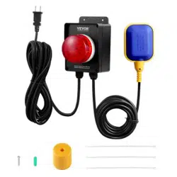
WATER LEVEL CONTROLLER
MODEL:SS-SW01
We continue to be committed to provide you tools with competitive price.
"Save Half", "Half Price" or any other similar expressions used by us only represents an
estimate of savings you might benefit from buying certain tools with us compared to the major
top brands and does not necessarily mean to cover all categories of tools offered by us. You
are kindly reminded to verify carefully when you are placing an order with us if you are
actually saving half in comparison with the top major brands.
- 2 -
MODEL:SS-SW01
Have product questions? Need technical support? Please feel free to
contact us:
Technical Support and E-Warranty Certificate
www.vevor.com/support
NEED HELP? CONTACT US!
This is the original instruction, please read all manual instructions
carefully before operating. VEVOR reserves a clear interpretation of our
user manual. The appearance of the product shall be subject to the
product you received. Please forgive us that we won't inform you again if
there are any technology or software updates on our product.
WATER LEVEL CONTROLLER
- 3 -
INSTRUCTIONS
The Water Level Controller is not rated for outdoor use. Its usually used in
application scenarios that require drainage, such as sewage pits. The
load will be turned on or off according to the condition of the water level
sensor.
Read and follow all instructions and safety guidelines thoroughly before
installing or operating the system. Failure to follow the instructions could
result in serious bodily injury or death and/or property/pump damage.
SAFETY GUIDELINES
1.Read and follow all safety guidelines and installation/operation instructions.
2.Follow all national, state or provincial,and local building,plumbing and
electrical codes and ordinances.
3.Do not install or operate the water lever controller while standing on a wet or
damp surface.
4.Do not energize the controller unit if an electrical component is damaged or
appears damaged or the controller unit is open.
5.Do not energize if there are wires disconnected or which appear
loose,frayed,or damaged.
6.Do not install the unit in locations classified as hazardous in accordance with
the most recent National Electrical Code.
Warning-To reduce the risk of injury, user must read
instructions manual carefully.
This device complies with Part 15 of the FCC Rules. Operation is
subject to the following two conditions:(1)This device may not cause
harmful interference, and (2)this device must accept any interference
received, including interference that may cause undesired operation.
- 4 -
7.Follow all installation/operation instructions and safety guidelines
accompanying the pumps and/or basin system.
READ PRIOR TO INSTALLATION
The installation of the water lever controller is simple and straight forward, but
there are TWO VERY IMPORTANT things to remember to give you years of
trouble free, worry free, service.
1. The“piggyback plug”attached to the mechanical float switch cannot be used
with the controller. It must be disconnected and remain disconnected.
2.
If your sump pump has internal float switch wiring, i.e., doesn’thave
a“piggyback plug,”then you must secure the float up as if the pit were full so
that its internal switch is always closed and the pump enabled.
Step-by-Step Installation(SUMP PIT)
Step 1:Unplug the sump pump from the back of piggyback plug
Step 2:Unplug the 'piggyback plug'
from the 120VAC and set aside. The
controller completely replaces this
component
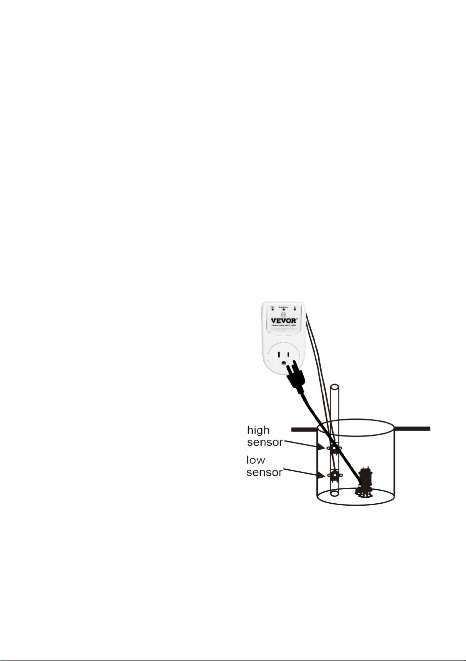
Step 3:Secure the HIGH SENSOR(HI)
to the discharge pipe or a piece of PVC
pipe with tie wrap where you want the
pump to turn on
NOTE: Recommended height for the
High sensor is slightly below the Drain
Tile(Water Inlet Pipe)
Step 4:Secure the LOW SENSOR(LO)
to the discharge pipe or a piece of PVC
pipe with tie wrap where you want the pump to turn off
Step 5: Check that the Low Sensor(LO) is positioned under the High Sensor
(HI) at a minimum of a 1” apart.
Step 6: Plug the control into the 120 VAC outlet. The 3 LEDS will illuminate
OFF(RED), DisAlarm (RED) and ON (GREEN) once indicating the controller is
ready to go. OFF(RED) indicates the output is off. A steady ON(GREEN)

- 5 -
means both sensors are detecting ware and the output is turned on. A flashing
ON(GREEN) indicates the output is on and only one sensor is detecting water.
NOTE: If the High Sensor detects water, a pump cycle will begin.
Step 7: Plug the sump pump motor into the control module
NOTE: The controller output is rated for a maximum of 1HP at 120VAC,
Step 8: Important! TEST YOUR INSTALLATION BEFORE LEAVINGIT FOR
UNATTENDED USE.Fill the pit with water until the water level reaches the tip
of the Hi Sensor. The pump should turn on and the water level drop.When the
water drops below the tip of the Low Sensor,the switch should turn off the
pump.
Switch Trouble shooting Chart
The Water Level Controller has a number of built in alarms that warn of
problems with the pump or discharge plumbing. The available alarms are
described in the table below.
Alarm & LED Guide
Meaning
Possible Cause
Steady Red LED (OFF)
The switch's output is
off (the pump is off).
None—Normal
operation
Flashing Red LED
(OFF)
Pump off, water
detected by lower
sensor
None—Normal
operation
Steady Green LED (ON)
The switch's output is
on (the pump is
on).water detected by
both sensors
None—Normal
operation
Flashing Green LED (ON)
Pump on,water below
upper sensor, and
above lower sensor
None—Normal
operation
Flashing Green (ON) and
Red (OFF) LED
Sensors position is not
right
Low sensor is up and
high sensor is down

- 6 -
Steady Beep*
(High Water Alarm)
Water level did not drop
below the Lo Sensor
within 20 seconds of
pump cycle start.
Blocked or frozen
discharge pipe
BUTTON FUNCTIONS
Button
Method
Mute'
Button
While an alarm is active, press the ‘MUTE' button will silence
the alarm for 24hrs. (The DisAlarm Led will flash).Press the
‘MUTE’ button again it will cancel the silence, the RED LED
(DisAlarm) will go out.
Pressing and holding the 'Mute' Button for 6s to disable the
alarm until the switch is reset.The Dis Alarm Led will steady on,
indicating that the alarm was successfully disabled. Holding the
button will enable the alarm.

- 7 -
Manufacturer: Shanghaimuxinmuyeyouxiangongsi
Address: Shuangchenglu 803nong11hao1602A-1609shi, baoshanqu,
shanghai 200000 CN.
Imported to AUS: SIHAO PTY LTD. 1 ROKEVA STREETEASTWOOD NSW
2122 Australia
Imported to USA: Sanven Technology Ltd. Suite 250, 9166 Anaheim Place,
Rancho Cucamonga, CA 91730
REP
EC
E-CrossStu GmbH
Mainzer Landstr.69, 60329 Frankfurt am Main.
REP
UK
YH CONSULTING LIMITED.
C/O YH Consulting Limited Office 147, Centurion House,
London Road, Staines-upon-Thames, Surrey, TW18 4AX