FormNo.3442-428RevA
TITAN®MaxServiceManual
Published:XX2020
©2020—TheToro®Company
8111LyndaleAvenueSouth
Bloomington,MN55420
OriginalInstructions(EN)
Contactusatwww.Toro.com.
AllRightsReserved

RevisionHistory
RevisionHistoryPage2
TITAN®MaxServiceManual
3442-428RevA

Preface
ThisservicemanualwaswrittenexpresslyforToroservicetechnicians.TheT oroCompanyhasmade
everyefforttomaketheinformationinthismanualcompleteandcorrect.
Basicshopsafetyknowledgeandmechanical/electricalskillsareassumed.TheT ableofContentslists
thesystemsandtherelatedtopicscoveredinthismanual.
Wearehopefulthatyouwillndthismanualavaluableadditiontoyourserviceshop.Ifyouhaveany
questionsorcommentsregardingthismanual,pleasecontactusatthefollowingaddress:
TheToroCompany
RLC/SWSCustomerCareDepartment
8111LyndaleAvenueSouth
Bloomington,MN55420
TheT oroCompanyreservestherighttochangeproductspecicationsormakechangestothismanual
withoutnotice.
TITAN®MaxServiceManual
Page3
Preface
3442-428RevA
ServiceProcedureIcons
ThefollowingiconsappearthroughoutthisServiceManualtobringattentionto
specicimportantdetailsofaserviceprocedure.
CriticalProcess
Thisiconisusedtohighlight:
•Installingsafetyequipment(shields,guards,seatbelts,brakes,andR.O.P .S.
components)thatmayhavebeenremoved
•Dimensionsorsettingsthatmustbemaintainedforpropermachineoperation
•Aspecicfastenertighteningsequence
•Componentorientationthatmaynotbeobvious
CriticalTorque
Thisiconisusedtohighlightanassemblytorquerequirementthatisdifferent
thanwhatisrecommendedintheStandardT orqueT ables.
FluidSpecications
Thisiconisusedtohighlightuidspecicationsandcapacitiesthatareless
common,andmaynotappearonthemachineservicedecalorinthemachine
Operator’sManual.
Note:RefertotheservicedecalonthemachineandthemachineOperator’s
Manualforcommonlyuseduidspecicationsandcapacities.
Preface
Page4
TITAN®MaxServiceManual
3442-428RevA

TableofContents
Preface................................................................................................................3
Chapter1:Safety............................................................................................1–1
SafetyInstructions.......................................................................................1–2
Chapter2:SpecicationsandMaintenance....................................................2–1
Specications...............................................................................................2–2
TorqueSpecications...................................................................................2–3
Chapter3:Troubleshooting.............................................................................3–1
GeneralTroubleshooting..............................................................................3–3
Chapter4:Engine...........................................................................................4–1
GeneralInformation.....................................................................................4–2
ServiceandRepairs.....................................................................................4–3
Chapter5:Chassis..........................................................................................5–1
GeneralInformation.....................................................................................5–2
ServiceandRepairs.....................................................................................5–3
Chapter6:MowerDeck...................................................................................6–1
GeneralInformation.....................................................................................6–2
ServiceandRepairs.....................................................................................6–3
Chapter7:HydrostaticDriveSystem...............................................................7–1
GeneralInformation.....................................................................................7–2
ServiceandRepairs.....................................................................................7–3
Chapter8:ElectricalSystem...........................................................................8–1
GeneralInformation.....................................................................................8–2
ServiceandRepairs.....................................................................................8–3
AppendixA......................................................................................................A–1
ElectricalDrawingAbbreviations...................................................................A–2
KohlerEngineElectricalSchematic..............................................................A–3
TITAN®MaxServiceManual
Page5
Preface
3442-428RevA

Preface
Page6
TITAN®MaxServiceManual
3442-428RevA

Chapter1
Safety
TableofContents
SafetyInstructions................................................................................................................................1–2
ThinkSafetyFirst...............................................................................................................................1–2
TITAN®MaxServiceManual
Page1–1
Safety
3442-428RevA
SafetyInstructions
DANGER
Thissafetysymbolmeansdanger.Whenyouseethissymbol,
carefullyreadtheinstructionsthatfollow.Failuretoobeythe
instructionscouldcauseseriouspermanentinjury,disability,or
death.
WARNING
Thissafetysymbolmeanswarning.Whenyouseethissymbol,
carefullyreadtheinstructionsthatfollow.Failuretoobeythe
instructionscanresultinseriousinjury.
CAUTION
Thissafetysymbolmeanscaution.Whenyouseethissymbol,
carefullyreadtheinstructionsthatfollow.Failuretoobeythe
instructionscanresultinminortomoderateinjuryand/ordamage
topropertyorequipment.
ThinkSafetyFirst
Avoidunexpectedstartingofengine…
Alwaysturnofftheengine,removetheignitionkeyanddisconnectthesparkplug
wire(s)beforecleaning,adjusting,orrepair.
Avoidlacerationsandamputations…
Stayclearofallmovingpartswhenevertheengineisrunning.Treatallnormally
movingpartsasiftheyweremovingwhenevertheengineisrunningorhas
thepotentialtostart.
Avoidburns…
Donottouchtheengine,mufer,orothercomponents,whichmaybehotduring
operation,whiletheunitisrunningorshortlyafterithasbeenrunning.
Avoidresandexplosions…
Useextremecareinhandlingfuel.Itisammableanditsvaporsareexplosive.
Extinguishallcigarettes,cigars,pipes,andothersourcesofignition.Avoid
spillingfuelandneversmokewhileworkingwithanytypeoffuelorlubricant.
Wipeupanyspilledfueloroilimmediately.Neverremovethefuelcaporadd
fuelwhentheengineisrunning.Alwaysuseapproved,labeledcontainersfor
storingortransportingfuelandlubricants.Donotaddordrainfuelinanenclosed
space.Donotstorethemachineorfuelcontainerwherethereisanopename,
spark,orpilotlight,suchasonawaterheaterorotherappliance.
Avoidasphyxiation…
Donotoperateanengineinaconnedareawithoutproperventilation.
Avoidinjuryfrombatteries…
Safety:SafetyInstructions
Page1–2
TITAN®MaxServiceManual
3442-428RevA

ThinkSafetyFirst(continued)
Batteryacidispoisonousandcancauseburns.Avoidcontactwithskin,eyes
andclothing.Batterygasescanexplode.Keepcigarettes,sparksandames
awayfromthebattery.
Avoidinjuryduetoinferiorparts…
Useonlyoriginalequipmentpartstoensurethatimportantsafetycriteriaaremet.
Avoidinjurytobystanders…
Alwayscleartheareaofbystandersbeforestartingortestingpowered
equipment.
Avoidinjuryduetoprojectiles…
Alwayscleartheareaofsticks,rocksoranyotherdebristhatcouldbepickedup
andthrownbythepoweredequipment.
Avoidmodications…
Neveralterormodifyanypartunlessitisafactoryapprovedprocedure.
Avoidunsafeoperation…
Alwaystestthesafetyinterlocksystemaftermakingadjustmentsorrepairson
themachine.RefertotheElectricalsectioninthismanualformoreinformation.
Avoidelectricalshock…
Nevertouchelectricalwiresorcomponentswhiletheengineisrunning.They
canbesourcesofshock.De-energizethesystemifyouarehavingtodorepairs.
Iftestingelectricalcomponentsensureyouareworkinginadryenvironment.
HydraulicSystem...
Releaseallpressureinthehydraulicsystembeforeperforminganyworkon
thesystem.Keepyourbodyandhandsawayfrompin-holeleaksornozzles
thatejecthydraulicuidunderhighpressure.Donotuseyourhandstosearch
forleaks.Hydraulicuidescapingunderpressurecanhavesufcientforceto
penetrateundertheskinandcauseseriousinjury.Seekmedicalattentionright
awayifhydraulicuidgetsintheskin.
PersonalProtectiveEquipment…
Tiebacklonghair,anddonotwearlooseclothingorjewelry.Useappropriate
personalprotectiveequipment(PPE)forprotectingyourselffrompotential
hazardsintheenvironmentinwhichyouwillwork.Eachprocessoutlinedinthis
manualmayneeddifferentPPEtoprotecttheserviceperson.Usetheproper
PPEforthetaskathand.
Tools…
Alltoolsshouldbeinproperworkingorder.Donotusetoolsthatarebrokenorin
disrepair.Usethepropertoolfortheproperapplication.
Lifts,Hoists,andJacks…
Alllifts,hoists,andjacksshouldbeusedinaccordancewiththemanufacturer
information.Inspectlifts,hoists,andjackspriortouse.Donotoverloadlifts,
hoists,andjacks.Donotworkunderasuspendedload.Ensurechockblocks
areusedonequipmentthatcanmove.Useliftsorjacksandjackstandsthat
areratedtosupportthetotalweightofthemachineandanyattachments.Do
notrelyonjackstosupportthemachine.Ifyouareunsureoftheoperationof
anylifts,hoists,andjacksdonotuse.
FireExtinguishers…
TITAN®MaxServiceManual
Page1–3
Safety:SafetyInstructions
3442-428RevA

ThinkSafetyFirst(continued)
Theproperclassofreextinguishershouldbeusedincaseofre.
ClassAextinguishersareforordinarycombustiblematerialssuchaspaper,
wood,cardboard,andmostplastics.Thenumericalratingonthesetypesof
extinguishersindicatestheamountofwateritholdsandtheamountofreitcan
extinguish.Geometricsymbol(greentriangle).
ClassBresinvolveammableorcombustibleliquidssuchasgasoline,
kerosene,greaseandoil.ThenumericalratingforclassBextinguishers
indicatestheapproximatenumberofsquarefeetofreitcanextinguish.
Geometricsymbol(redsquare).
ClassCresinvolveelectricalequipment,suchasappliances,wiring,circuit
breakersandoutlets.NeverusewatertoextinguishclassCres-theriskof
electricalshockisfartoogreat!ClassCextinguishersdonothaveanumerical
rating.TheCclassicationmeanstheextinguishingagentisnon-conductive.
Geometricsymbol(bluecircle).
ABCreextinguishersareadrychemicaltypeusedformultiplepurposes.See
aboveinformationfordescription.Ensurereextinguishersareserviceableand
replaceanythataredischargedoroutofinspectiondates
Safety:SafetyInstructions
Page1–4
TITAN®MaxServiceManual
3442-428RevA

Chapter2
SpecicationsandMaintenance
TableofContents
Specications.......................................................................................................................................2–2
TorqueSpecications...........................................................................................................................2–3
EquivalentsandConversions.............................................................................................................2–8
U.S.toMetricConversions................................................................................................................2–9
TITAN®MaxServiceManual
Page2–1
SpecicationsandMaintenance
3442-428RevA

Specications
TITAN®MaxSpecications
Model76601
Engine
26HPKohlerwithProAirCleaner
EngineModelKT745-3094
EngineDisplacement747cc
EngineSpeed
3600±100
EngineOilCapacity1.9L(64oz)withoillter
Frame/AxleWidth
FullyWeldedTubularFrame
DeckSize152.4cm(60inches)
DeckConguration
3-Blade
DeckConstruction
Fabricated
HOCType
4Point
HOCRange3.81–12.7cm(1.5-5.0inches)
FuelTankCapacity26.5L(7gallons)
CARBCompliant
No
EPAComplaint
Yes
ClutchWarner142.36N•m(105ft-lb)
Hydros
Hydro-GearZT-3100
HydroOilCapacity(WithFiltersRemoved)4.45L(1.2gallons)
UnitSpeed
9.0mph
RearWheels/Tires58.42x3.48–30.48cm(23x12-12inches)
CastorTires13x6.5-6Smooth
Seat(INCwithArmrests)60.96cm(24inch)SeatsINCwitharmrests
SeatSlideLeverSlide
FloorMatMoldedRubber
Recycler
Optional
BaggingSystemOptional
Hourmeter
Standard
FootLiftAssistStandard
DeckSpringAssistN/A
HitchKit
Standard
Anti-scalpeRollersYes
BatterySize300CCA
GrossWeight(lb)
Unit876
Length
208.79cm(82.2inches)
Width(DeectorDown)191.3cm(75.3inches)
Width(DeectorUp)160.5cm(63.2inches)
Height(ROPSDown)116cm(45.7inches)
Height(ROPSUp)179.6cm(70.7inches)
SpecicationsandMaintenance:Specications
Page2–2
TITAN®MaxServiceManual
3442-428RevA
TorqueSpecications
Therecommendedfastenertorquevaluesarelistedinthefollowingtables.For
criticalapplications,asdeterminedbyToro,eithertherecommendedtorqueora
torquethatisuniquetotheapplicationisclearlyidentiedandspeciedinthe
servicemanual.
Thesetorquespecicationsfortheinstallationandtighteningoffastenersshall
applyforallfastenerswhichdonothaveaspecicrequirementidentiedin
theservicemanual.Thefollowingfactorsshallbeconsideredwhenapplying
torque:cleanlinessofthefastener,useofathreadsealant(Loctite),degreeof
lubricationonthefastener,presenceofaprevailingtorquefeature,hardness
ofthesurfaceunderneathofthefastener’shead,orsimilarconditionwhich
affectstheinstallation.
Asnotedinthefollowingtables,torquevaluesshouldbereducedby25%for
lubricatedfastenerstoachievethesimilarstressasadryfastener.Torquevalues
mayalsohavetobereducedwhenthefasteneristhreadedintoaluminumor
brass.Thespecictorquevalueshouldbedeterminedbasedonthealuminum
orbrassmaterialstrength,fastenersize,lengthofthreadengagement,etc.
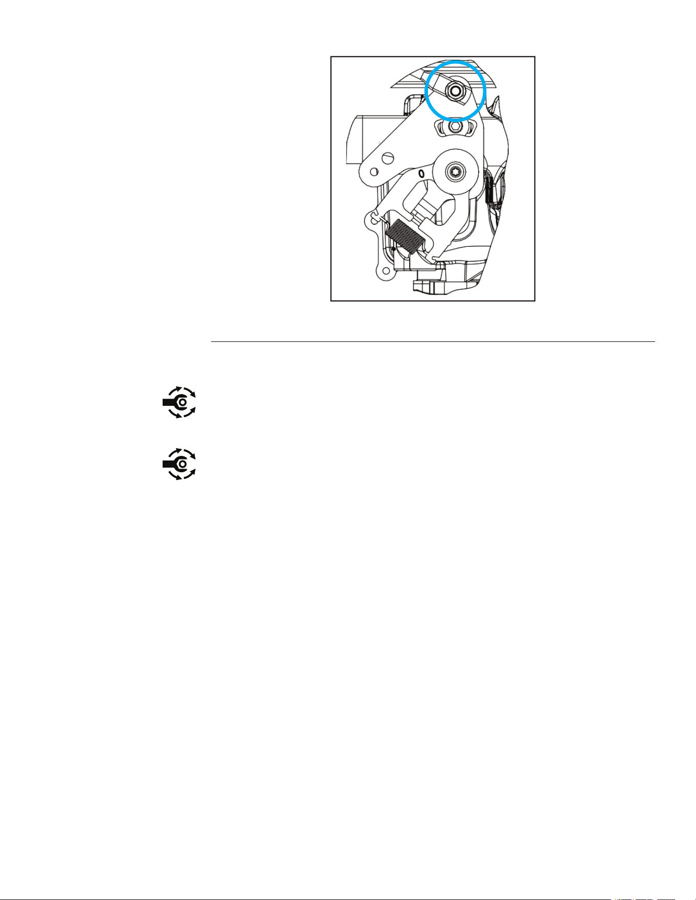
Thestandardmethodofverifyingtorqueshallbeperformedbymarkingalineon
thefastener(headornut)andmatingpart,thenbackofffastener1/4ofaturn.
Measurethetorquerequiredtotightenthefasteneruntilthelinesmatchup.
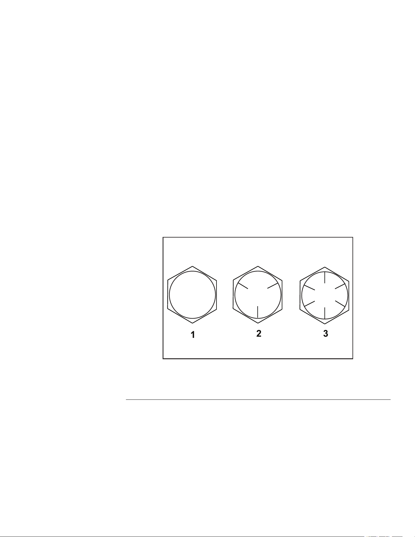
FastenerIdentication
InchSeriesBoltsandScrews
g272208
Figure1
1.Grade13.Grade8
2.Grade5
TITAN®MaxServiceManual
Page2–3
SpecicationsandMaintenance:TorqueSpecications
3442-428RevA

StandardTorqueforDry,ZincPlated,andSteelFasteners(InchSeries)
ThreadSizeGrade1,
5,&8
Fasteners
withThin
HeightNuts
SAEGrade1Bolts,Screws,
Studes&Semswith
RegularHeightNuts(SAE
Grade2orBetterNut)
SAEGrade5Bolts,Screws,
Studs&SemswithRegular
HeightNuts(SAEGrade
5orBetterNut)
SAEGrade8Bolts,Screws,
Studs&SemswithRegular
HeightNuts(SAEGrade
8orBetterNut)
in-lbin-lbN•cmin-lbN•cmin-lbN•cm
#6-32UNC
15±2169±2323±3260±34
#6-40UNF
10±213±2147±23
17±2192±2325±3282±34
#8-32UNC
29±3328±3441±5463±56
#8-36UNF
13±225±5282±30
31±4350±4543±5486±56
#10-24UNC
42±5475±5660±6678±68
#10-32UNF
18±230±5339±56
48±5542±5668±7768±79
1/4-20UNC
48±753±7599±79100±101130±113140±151582±169
1/4-28UNF
53±765±10734±113115±121299±136160±171808±192
5/16-18UNC
115±15105±151186±169200±252260±282300±303390±339
5/16-24UNF
138±17128±171446±192225±252542±282325±333672±373
ft-lbft-lb
N•m
ft-lb
N•m
ft-lb
N•m
3/8-16UNC
16±216±222±330±341±443±558±7
3/8-24UNF
17±218±224±335±447±550±668±8
7/16-14UNC
27±327±337±450±568±770±795±9
7/16-20UNF
29±329±339±455±675±877±8104±11
1/2-13UNC
30±348±765±975±8102±11105±11142±15
1/2-20UNF
32±453±772±985±9115±12120±12163±16
5/8-11UNC
65±1088±12119±16150±15203±20210±21285±28
5/8-18UNF
75±1095±15129±20170±18230±24240±24325±33
3/4-10UNC
93±12140±20190±27265±27359±37375±38508±52
3/4-16UNF
115±15165±25224±34300±30407±41420±43569±58
7/8-9UNC
140±20225±25305±34430±45583±61600±60813±81
7/8-14UNF
155±25260±30353±41475±48644±65667±66904±89
Note:Reducetorquevalueslistedinthetableaboveby25%forlubricatedfasteners.Lubricated
fastenersaredenedasthreadscoatedwithalubricantsuchasoil,graphite,orthreadsealantsuch
asLoctite.
Torquevaluesmyhavetobereducedwheninstallingfastenersintothreadedaluminumorbrass.The
specictorquevalueshouldbedeterminedbasedonthefastenersize,thealuminumorbasematerial
strength,lengthofthreadengagement,etc.
ThenominaltorquevalueslistedaboveforGrade5and8fastenersarebasedon75%oftheminimum
proofloadspeciedinSAEJ429.Thetoleranceisapproximately±10%ofthenominaltorquevalue.
Thinnutsincludejamnuts.
TITAN®MaxServiceManual
Page2–5
SpecicationsandMaintenance:TorqueSpecications
3442-428RevA

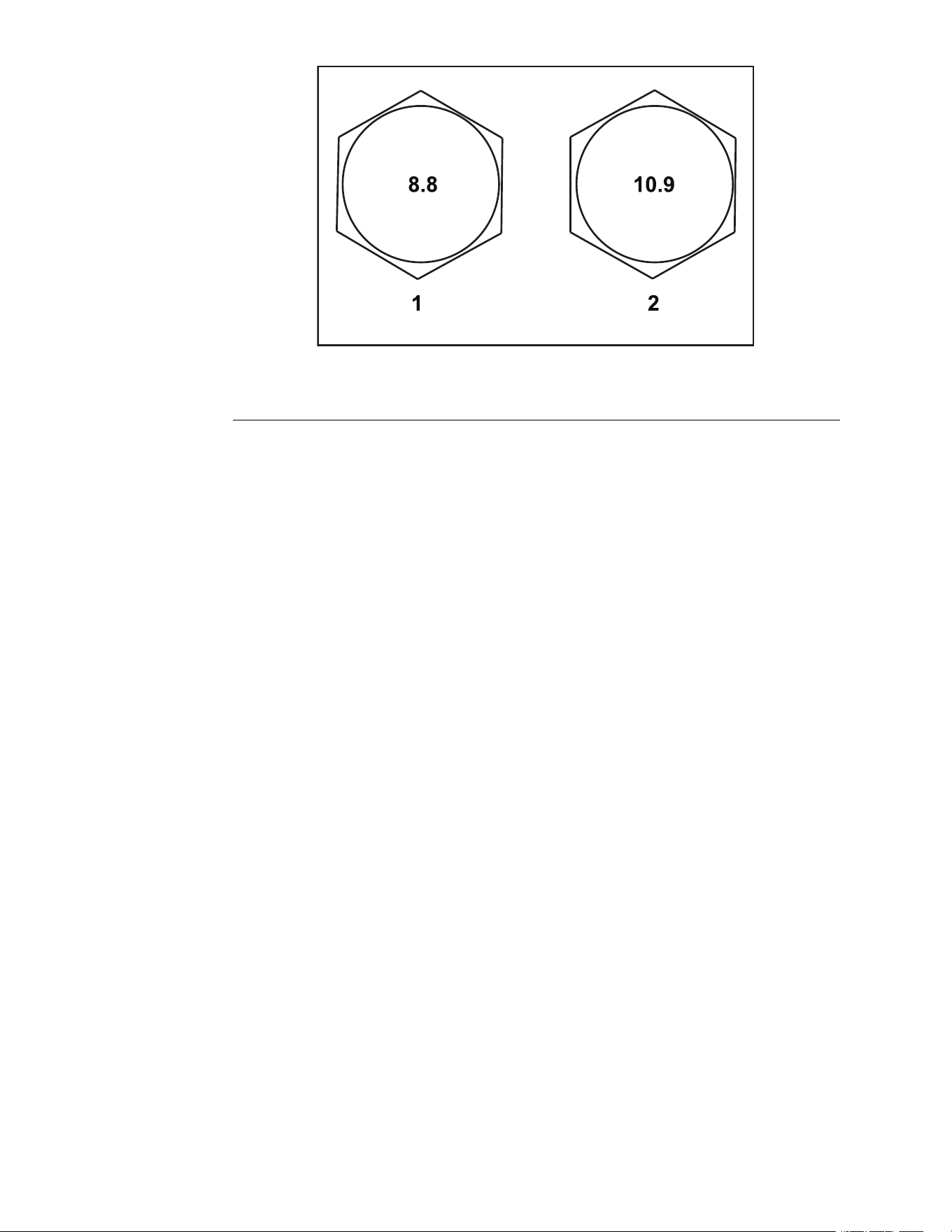
StandardTorqueforDry,ZincPlated,andSteelFasteners(MetricSeries)
Class8.8Bolts,Screws,StudswithRegular
HeightNuts(Class8orStrongerNuts)
Class10.9Bolts,Screws,StudswithRegular
HeightNuts(Class10orstrongerNuts)
ThreadSize
in-lbN•cmin-lbN•cm
M5X0.857±6644±6878±8881±90
M6X1.096±101085±113133±141503±158
ft-lb
N•m
ft-lb
N•m
M8X1.2519±226±328±338±4
M10X1.538±452±554±673±8
M12X1.7566±790±1093±10126±14
M16X2.0166±17255±23229±23310±31
M20X2.5325±33440±45450±46610±62
Note:Reducetorquevalueslistedinthetableaboveby25%forlubricatedfasteners.Lubricated
fastenersaredenedasthreadscoatedwithalubricantsuchasoil,graphite,orthreadsealantsuch
asLoctite.
Torquevaluesmayhavetobereducedwheninstallingfastenersintothreadedaluminumorbrass.The
specictorquevalueshouldbedeterminedbasedonthefastenersize,thealuminumorbasematerial
strength,lengthofthreadengagement,etc.
Thenominaltorquevalueslistedabovearebasedon75%oftheminimumproofloadspeciedinSAE
J1199.Thetoleranceisapproximately±10%ofthenominaltorquevalue.Thinheightnutsincludejam
nuts.
SpecicationsandMaintenance:TorqueSpecications
Page2–6
TITAN®MaxServiceManual
3442-428RevA
SAEGrade8SteelSetScrews
RecommendedTorque
ThreadSize
SquareHeadHexSocket
1/4-20UNC
140±20in-lb73±12in-lb
5/16-18UNC
215±35in-lb145±20in-lb
1/2-13UNC75±15ft-lb50±10ft-lb
3/8-16UNC35±10ft-lb18±3ft-lb
WheelBoltsandLugNuts
ThreadSizeRecommendedTorque**
7/16-20UNFGrade565±10ft-lb
88±14N•m
1/2-20UNFGrade580±10ft-lb
108±14N•m
M12X1.25Class8.880±10ft-lb
108±14N•m
M12X1.5Class8.880±10ft-lb
108±14N•m
**Forsteelwheelsandnon-lubricatedfasteners.
ThreadCuttingScrews(ZincPlatedSteel)
Type1,Type23,orTypeF
ThreadSizeBaselineTorque*
No.6-32UNC
20±5in-lb
No.8-32UNC
30±5in-lb
No.10-24UNC
38±7in-lb
1/4-20UNC
85±15in-lb
5/16-18UNC
110±20in-lb
3/8-16UNC
200±100in-lb
*Holesize,materialstrength,materialthicknessandnishmustbeconsideredwhendetermining
specictorquevalues.Alltorquevaluesarebasedonnon-lubricatedfasteners.
ConversionFactors
in-lbX11.2985=N•cm
ft-lbX1.3558=N•m
N•cmX0.08851=in-lb
N•cmX0.73776=ft-lb
ThreadCuttingScrews(ZincPlatedSteel)
ThreadsperInch
ThreadsSize
TypeATypeB
BaselineTorque*
No.6182020±5in-lb
No.8151830±5in-lb
No.10121638±7in-lb
No.12111485±15in-lb
*Holesize,materialstrength,materialthicknessandnishmustbeconsideredwhendetermining
specictorquevalues.Alltorquevaluesarebasedonnon-lubricatedfasteners.
TITAN®MaxServiceManual
Page2–7
SpecicationsandMaintenance:TorqueSpecications
3442-428RevA

EquivalentsandConversions
DecimalandMillimeterEquivalents
FractionsDecimals
mm
FractionsDecimals
mm
1/64
0.0156250.397
33/64
0.51562513.097
1/32
0.031250.794
16/32
0.5312513.484
3/64
0.0468751.191
35/64
0.54687513.891
1/16
0.06251.588
9/16
0.562514.288
5/64
0.0781251.984
37/64
0.57812514.684
3/32
0.93752.381
19/32
0.5937515.081
1/8
0.12503.175
5/8
0.625015.875
9/64
0.1406253.572
41/64
0.64062516.272
5/32
0.156253.969
21/32
0.6562516.669
11/64
0.1718754.366
43/64
0.67187517.066
3/16
0.18754.762
11/64
0.687517.462
13/64
0.2031255.159
45/64
0.70312517.859
7/32
0.218755.556
23/32
0.7187518.256
15/64
0.2343755.953
47/64
0.73437518.653
1/4
0.25006.350
3/4
0.750019.050
17/64
0.2656256.747
49/64
0.76562519.447
9/32
0.281257.144
25/32
0.7812519.844
19/64
0.2968757.541
51/64
0.79687520.241
5/16
0.31257.541
13/16
0.812520.638
21/64
0.3281258.334
53/64
0.82812521.034
11/32
0.343758.731
27/32
0.8437521.431
23/64
0.3593759.128
55/64
0.85937521.828
3/8
0.37509.525
7/8
0.875022.225
25/64
0.3906259.922
57/64
0.89062522.622
13/32
0.4062510.319
29/32
0.9062523.019
27/64
0.42187510.716
59/64
0.92187523.416
7/16
0.437511.112
15/16
0.937523.812
29/64
0.45312511.509
61/64
0.95312524.209
15/32
0.4687511.906
31/32
0.9687524.606
31/64
0.48437512.303
63/64
0.98437525.003
1/2
0.500012.70011.00025.400
1mm=0.03937in.0.001in.=0.0254mm
SpecicationsandMaintenance:TorqueSpecications
Page2–8
TITAN®MaxServiceManual
3442-428RevA

U.S.toMetricConversions
ToConvert
IntoMultiplyBy
MilesKilometers1.609
YardsMeters0.9144
FeetMeters0.3048
Feet
Centimeters
30.48
InchesMeters0.0254
Inches
Centimeters
2.54
LinearMeasurement
InchesMillimeters25.4
SquareMilesSquareKilometers
2.59
SquareFeetSquareMeters
0.0929
SquareInchesSquareCentimeters
6.452
Area
AcreHectare0.4047
CubicYardsCubicMeters
0.7646
CubicFeetCubicMeters
0.02832
Volume
CubicInchesCubicCentimeters
16.39
Tons(Short)
MetricT ons0.9078
PoundsKilograms0.4536 Weight
OuncesGrams
28.3495
Pressure
Pounds/SquareInch
Kilopascal6.895
Foot-PoundsNewton-Meters1.356
Foot-PoundsKilogram-Meters0.1383
Work
Inch-Pounds
Kilogram-Centimeters
1.152144
Quarts
Liters0.9463
LiquidVolume
Gallons
Liters3.785
LiquidFlows
Gallons/MinuteLiters/Minute
3.785
1.Subtractby32°
TemperatureFahrenheit
Celsius
2.Multiplyby5/9
TITAN®MaxServiceManual
Page2–9
SpecicationsandMaintenance:TorqueSpecications
3442-428RevA


GEARS
TheSystematicapproachtodening,diagnosingandsolvingproblems.
GatherInformation
•Informationreportedbythecustomer
•Informationobservedbyyou
G
•Establishthewhat,whereandwhenoftheissue
EvaluatePotentialCauses
•Considerpossiblecausesoftheproblemtodevelopahypothesis
E
•Narrowdownthefocusoftheproblem
AssessPerformance
•Ensureyouhaveallthenecessarytoolsfortesting
•T estallpotentialcausesofthefailure
A
•Reevaluateandcreatenewhypothesesifnecessary
Repair
R
•Returntheunittoservicebyrepairing,rebuildingorreplacing
SolutionConrmation
•Didtheissuegoaway
•Wastherootcauseoftheissuecorrectlyrepaired
S
•Arethereanyothernewsymptoms
Troubleshooting:GeneralTroubleshooting
Page3–2
TITAN®MaxServiceManual
3442-428RevA

GeneralTroubleshooting
Problem
PossibleCauseCorrectiveAction
Thebladecontrolswitch(PTO)is
engaged.
Movetheblade-controlswitch(PTO)to
thedisengagedposition.
Theparkingbrakeisnotengaged.
Settheparkingbrake.
Themotion-controlleversarenotinthe
Neutral-Lockposition.
Ensurethatthemotion-controllevers
areintheNeutral-Lockposition.
Thebatteryisdead.
Chargethebattery.
Theelectricalconnectionsarecorroded
orloose.
Checktheelectricalconnectsforgood
contact.
Thefuseisblown.Replacethefuse.
Thestarterdoesnotcrank
Therelayorswitchiswornordamaged.
Testandreplacefaultyrelayorswitch.
Thefueltankisempty.Fillthefueltank.
Thefuelshut-offvalveisclosed.Openthefuelshut-offvalve.
Theoillevelinthecrankcaseislow.Addoiltothecrankcase.
Thethrottleisnotinthecorrectposition.Besurethatthethrottlecontrolis
midwaybetweentheslowandfast
positions.
Thereisdirtinthefuellter.Replacethefuellter.
Thereisdirt,water,orstalefuelinthe
fuelsystem.
Cleanandushthefuelsystem.
Theaircleanerisdirty.
Cleanorreplacetheaircleaner
element.
Theseatswitchisnotfunctioning
properly.
Checktheseat-switchindicator.
Replacetheseatifnecessary.
Theelectricalconnectionsare
corroded,loose,ordamaged.
Checktheelectricalconnectionsfor
goodcontact.Cleantheconnector
terminalsthoroughlywithelectrical-
contactcleaner,applydielectricgrease,
andmaketheappropriateconnections.
Therelayorswitchiswornordamaged.
Testandreplacefaultyrelayorswitch.
Thesparkplugisfouledorimproperly
gapped.
Adjustorreplacethesparkplug.
Theenginedoesnotstart,starts
hard,orfailstokeeprunning
Thesparkplugwireisnotconnected.
Checkthesparkplugwireconnection.
Theengineloadisexcessive.Reducethegroundspeed.
Theaircleanerisdirty.
Cleantheaircleanerelement.
Theoillevelinthecrankcaseislow.Addoiltothecrankcase.
Thecoolingnsandairpassages
abovetheengineareplugged.
Removetheobstructionandthoroughly
cleancoolingnsandtheairpassages.
Theventholeinthefuelcapisplugged.Cleanorreplacethefuelcap.
Thereisdirtinthefuellter.Replacethefuellter.
Enginelosespower
Thereisdirt,water,orstalefuelinthe
fuelsystem.
Cleanandushthefuelsystem.
TITAN®MaxServiceManual
Page3–3
Troubleshooting:GeneralTroubleshooting
3442-428RevA

GeneralTroubleshooting(continued)
Problem
PossibleCauseCorrectiveAction
Theengineloadisexcessive.Reducethegroundspeed.
Theoillevelinthecrankcaseislow.Addoiltothecrankcase.
Theengineoverheats
Thecoolingnsandtheairpassages
abovetheengineareplugged.
Removetheobstructionandthoroughly
cleancoolingnsandtheairpassages.
Thetrackingneedsadjustment.Adjustthetracking.
Themowerpullstotheleftorright
(withleversfullyforward)
Thetirepressureinthedrivetiresis
notcorrect.
Adjustthetirepressureinthedrive
tires.
Thebypassvalvesarenotclosedtight.Tightenthebypassvalves.
Thepumpbeltisworn,looseorbroken.
Changethebelt.
Thepumpbeltisoffapulley.Changethebelt.
Theidlerspringisbrokenormissing.Replacethespring.
Themachinedoesnotdrive
Thehydraulicoillevelislowortoohot.Addhydraulicoiltothereservoirsorlet
itcooldown.
Thecuttingblade(s)is/arebentor
unbalanced.
Installnewcuttingblade(s).
Theblademountingboltisloose.Tightentheblademountingbolt.
Theenginemountingboltsareloose.Tightentheenginemountingbolts.
Theenginepulley,idlerpulley,orblade
pulleyisloose.
Tightentheappropriatepulley,check
tomakesureidlerspringsarenotover
stretched.
Theenginepulleyisdamaged.Replacetheenginepulley.
Thebladespindleisbent.Replacethespindle.
Themachinevibratesabnormally
Themotormountislooseorworn.
Checkthemountingbolts.
Theblade(s)is/arenotsharp.Sharpentheblade(s).
Thecuttingblade(s)is/arebent.Installnewcuttingblade(s).
Themowerdeckisnotlevel.
Levelthemowerdeckfromside-to-
sideandfront-to-rear.
Theundersideofmowerisdirty.Cleantheundersideofthemower.
Thetirepressureisnotcorrect.Adjustthetirepressure.
Themachineproducesanuneven
cuttingheight
Thebladespindleisbent.Replacethespindle.
Themowerdeckbeltisdamaged,
worn,loose,orbroken.
Installanewdeckbelt.
Themowerdeckbeltisoffthepulley.
Installthemowerbeltonthedeck
pulleyandchecktheidlerpulley,idler
arm,andspringforcorrectpositionand
function.
Thepumpdrivebeltisworn,looseor
broken.
Checkthebelttensionorinstallanew
belt.
Thebladesdonotrotate
Theidlerspringisbrokenormissing.Replacethespring.
Troubleshooting:GeneralTroubleshooting
Page3–4
TITAN®MaxServiceManual
3442-428RevA

GeneralTroubleshooting(continued)
Problem
PossibleCauseCorrectiveAction
Thefuseisblown.Replacethefuse.Checkthecoil
resistance,batterycharge,charging
system,andwiringconnections,and
replacecomponentsifnecessary.
Thereisalowvoltagesupplyatthe
clutch.
Checkthecoilresistance,battery
charge,chargingsystem,andwiring
connectionsandreplacepartsif
necessary.
Thecoilisdamaged.Replacetheclutch.
Thereisinadequatecurrentsupply.Repairorreplacetheclutchleadwireor
electricalsystem.Cleantheconnector
contacts.
Theclutchdoesnotengage
Therotor/armatureairgapistoolarge.
Removetheshimorreplacetheclutch.
TITAN®MaxServiceManual
Page3–5
Troubleshooting:GeneralTroubleshooting
3442-428RevA


Chapter4
Engine
TableofContents
GeneralInformation..............................................................................................................................4–2
ServiceandRepairs.............................................................................................................................4–3
EngineReplacement..........................................................................................................................4–4
TITAN®MaxServiceManual
Page4–1Engine
3442-428RevA

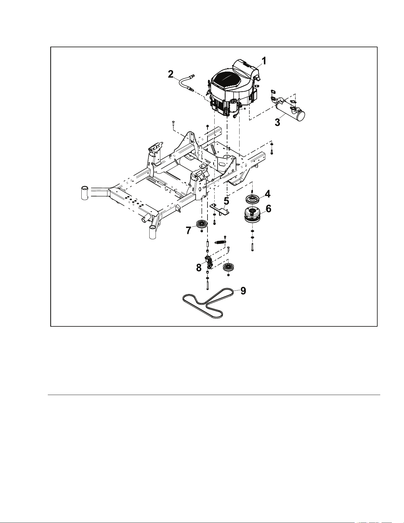
EngineReplacement
EngineRemoval
1.ParkthemachineonalevelsurfaceanddisengagethePTO.Stoptheengine,
waitforallmovingpartstostop,andremovekey.Engagetheparkingbrake.
2.Disconnectthebatterybyremovingthenegativecablerst,thenthepositive
cablefromthebattery.
3.Draintheoilintoasuitablecontainer.
4.Closethefuelsupply.
g344221
Figure4
5.Removetheengineguard.
6.Removethedeckdrivebeltfromthemowerdeck.DeckDriveBeltRemoval
(page6–10)
7.Removethehydrostaticdrivebeltfromthemachine.HydrostaticDriveBelt
Removal(page7–8)
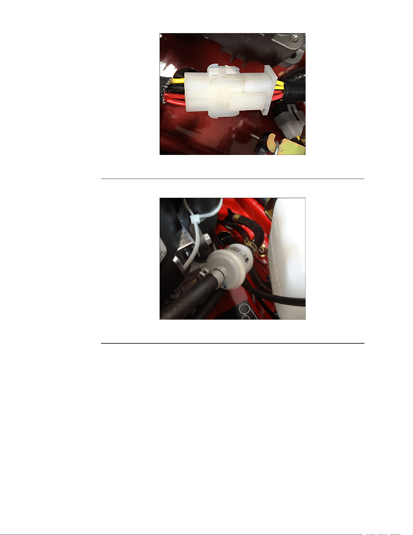
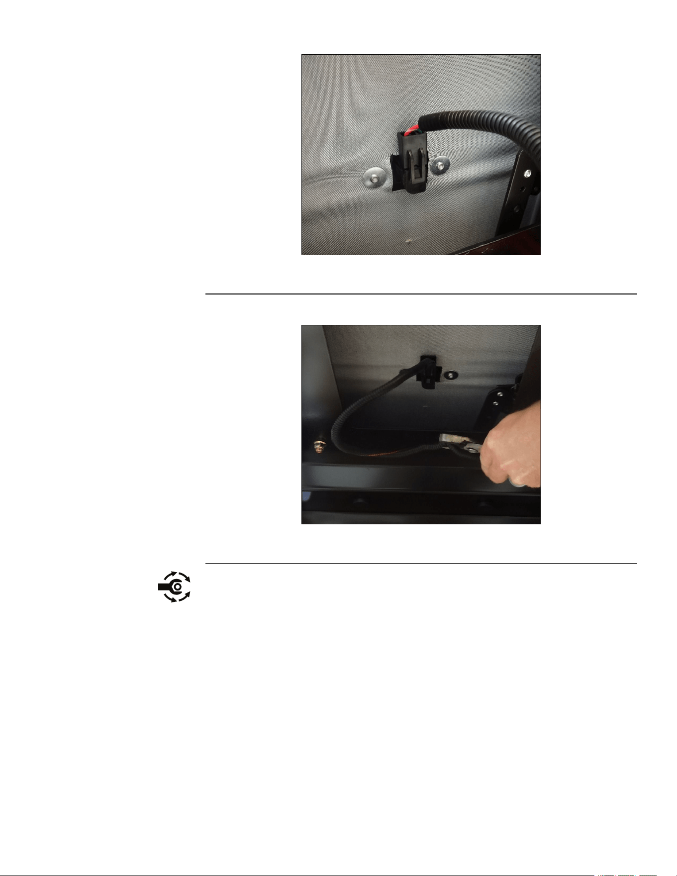
8.Disconnectthechassiswireharnessfromthemainenginewireharness.
g335893
Figure5
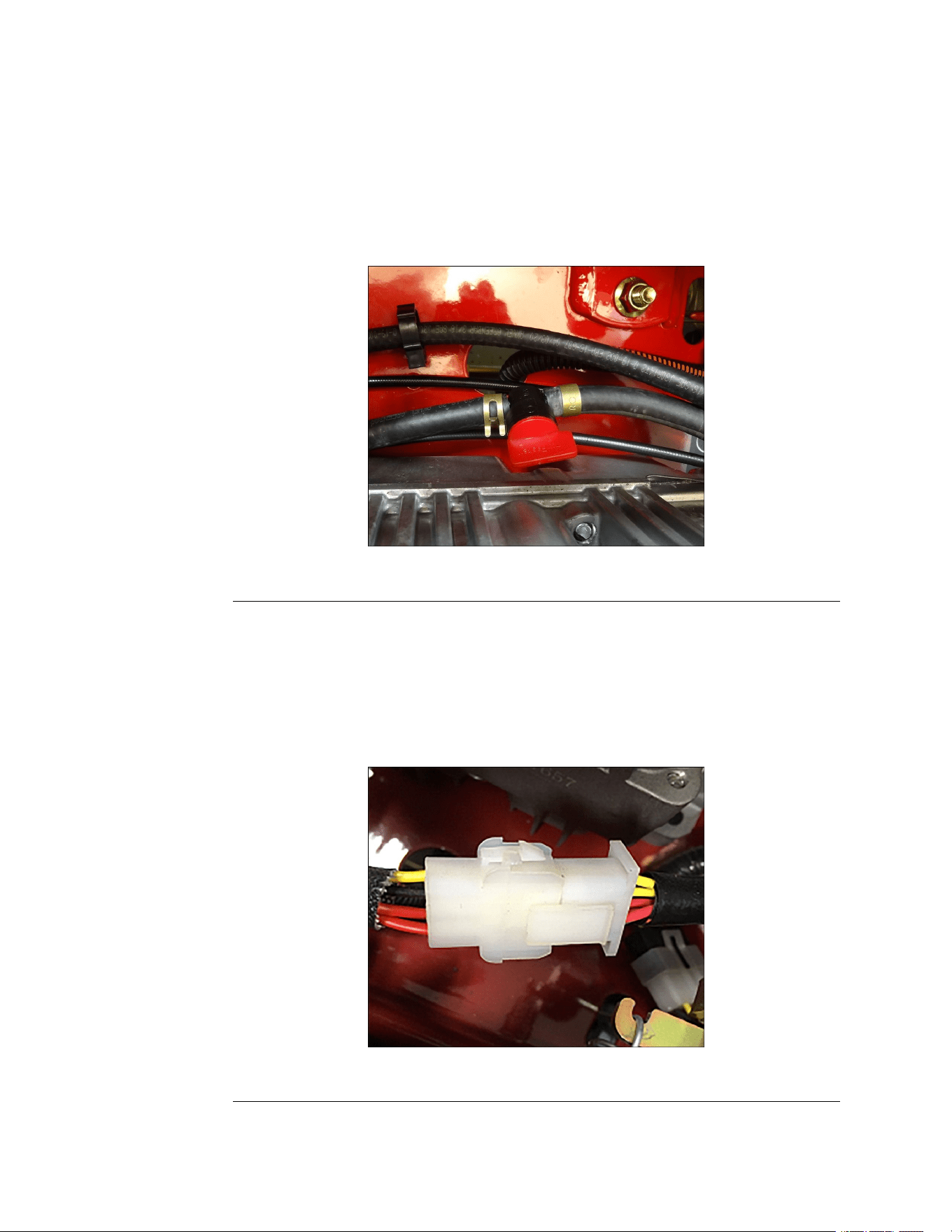
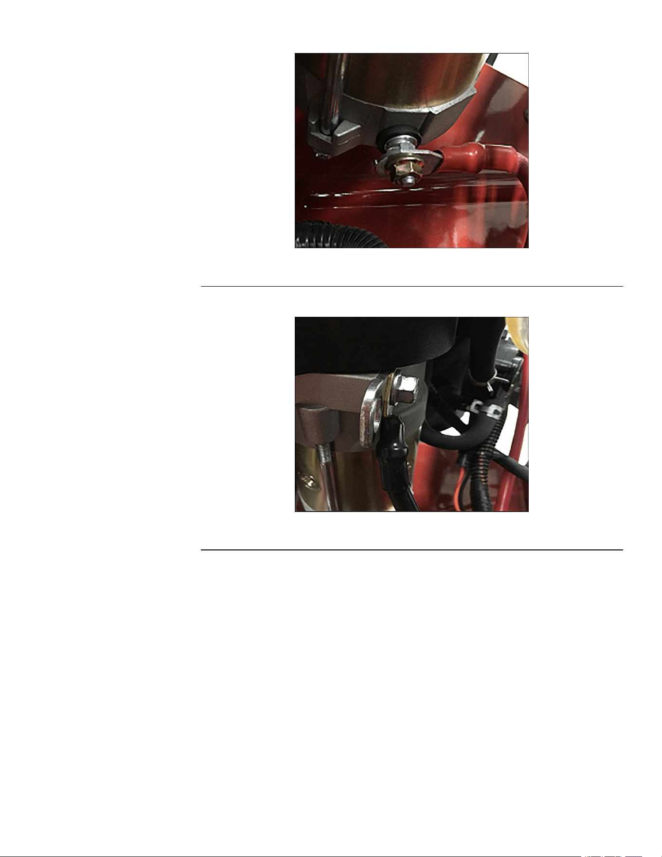
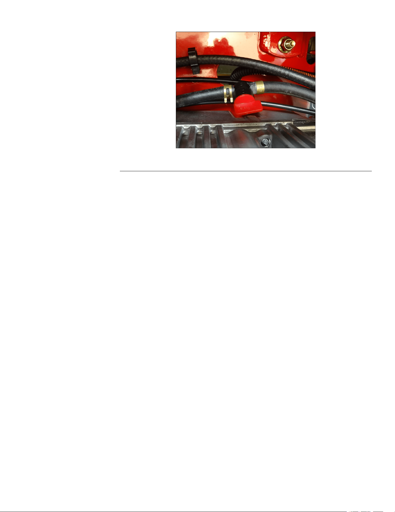
9.Disconnectthered(B+)wirefromthestarter.
Engine:ServiceandRepairs
Page4–4
TITAN®MaxServiceManual
3442-428RevA
EngineRemoval(continued)
g349637
Figure8
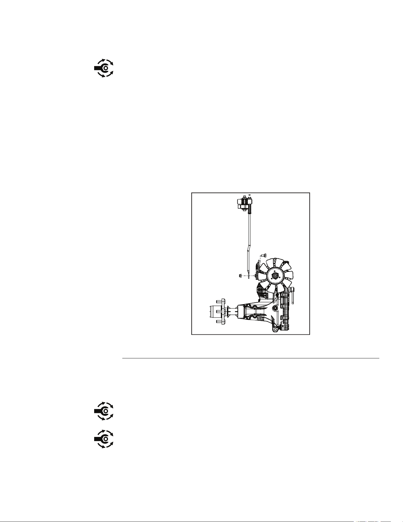
12.Disconnectthethrottlecable.ThrottleCableAssemblyRemoval(page5–26)
13.Disconnectthechokecable.ChokeControlAssemblyRemoval(page5–29)
14.Disconnecttheclutchwirefromtheclutch.
15.Removethe(7/16x3inch)clutchmountingscrewand2washers.Slipthe
clutchoffofthecrankshaft.
Note:Beforeremovingtheclutch,notetheorientationoftheclutchwire
andtheclutch.
16.Removetheenginepulley.Retainthesquarekeysecuringthepulleyto
thecrankshaft.
17.Removethe4(0.375-16x1.500inch)enginemountingscrews.
Note:Beforeremovingtheenginemountingscrews,notetheorientationof
theclutchanchor.Theclutchwirecanremainattachedtotheclutchanchor.
18.Removetheenginefromtheframe.
EngineInstallation
1.Preparetheframeandsecureanyfuellinesorwireharnesscomponents.
2.Installtheengineontotheframe.
3.Alignthe4holesoftheenginebasetotheframeandattachthe2(0.375-16
x1.500inch)rearmountingscrewsandbellevillewashersloosely.
4.Attachthefront2screwsandbellevillewashersthroughtheclutchanchor
andintotheenginebase.
5.Torquethe4screwsto36.6–44.7N•m(27–33ft-lb).
6.Installthekeyandenginepulleyontothecrankshaft.
Note:Installtheenginepulleywiththelargerdiameterhubtowardtheengine.
7.Installtheclutchontothecrankshaftensuringthattheslotintheclutchaligns
withthetabontheclutchanchor.
8.Installthe2springwashersandthe(7/16x3inch)clutchscrew.T orquethe
screwto66.4–82.7N•m(49-61ft-lb).
Engine:ServiceandRepairs
Page4–6
TITAN®MaxServiceManual
3442-428RevA
EngineInstallation(continued)
9.Installthehydrostaticdrivebeltontothemachine.HydrostaticDriveBelt
Installation(page7–8)
10.Installthedeckdrivebeltontothemowerdeck.DeckDriveBeltInstallation
(page6–12)
11.Connecttheclutchwiretotheclutch.
12.Connectthechokecable.ChokeControlAssemblyRemoval(page5–29)
13.Connectthethrottlecable.ThrottleCableAssemblyInstallation(page5–27)
14.Connecttheblackenginegroundwire.
g344817
Figure9
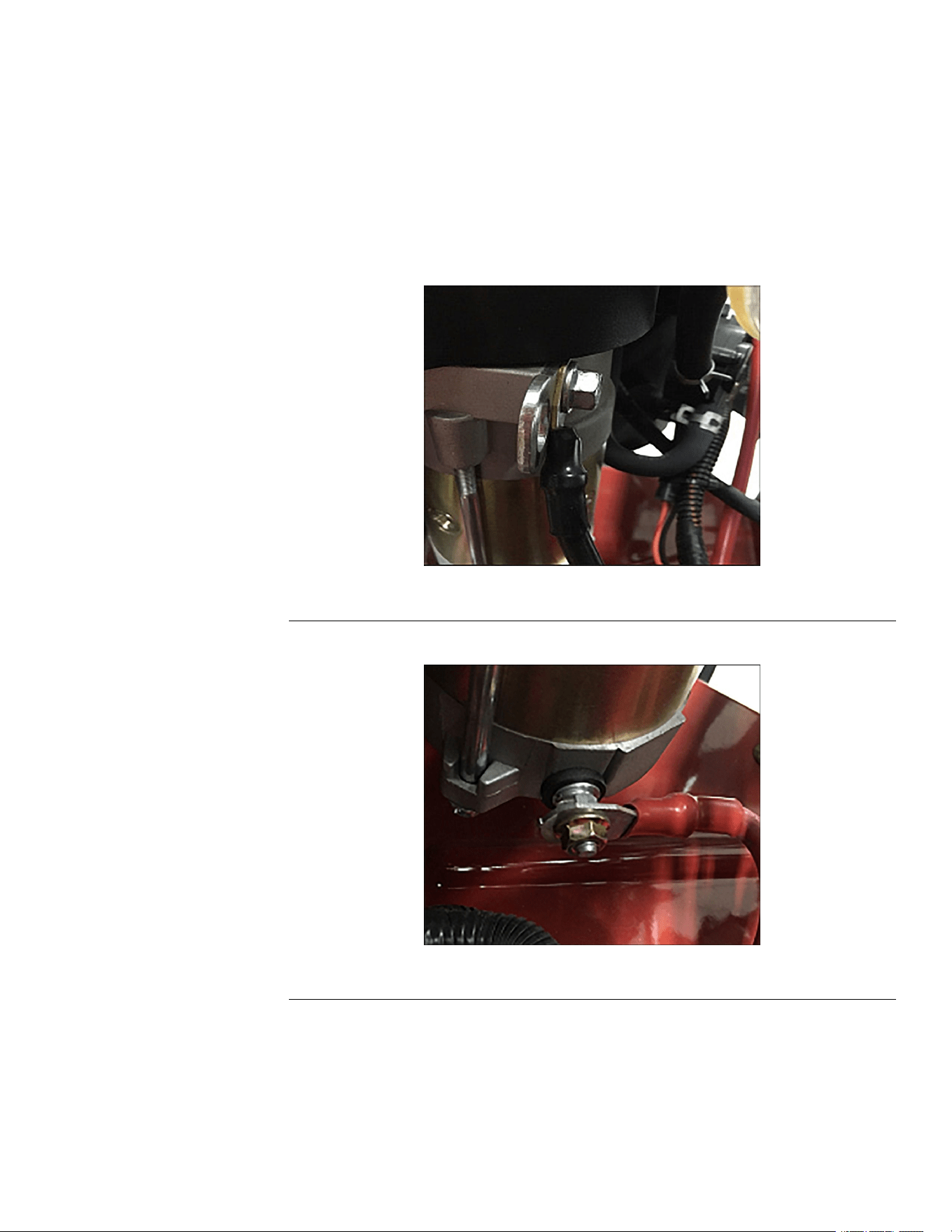
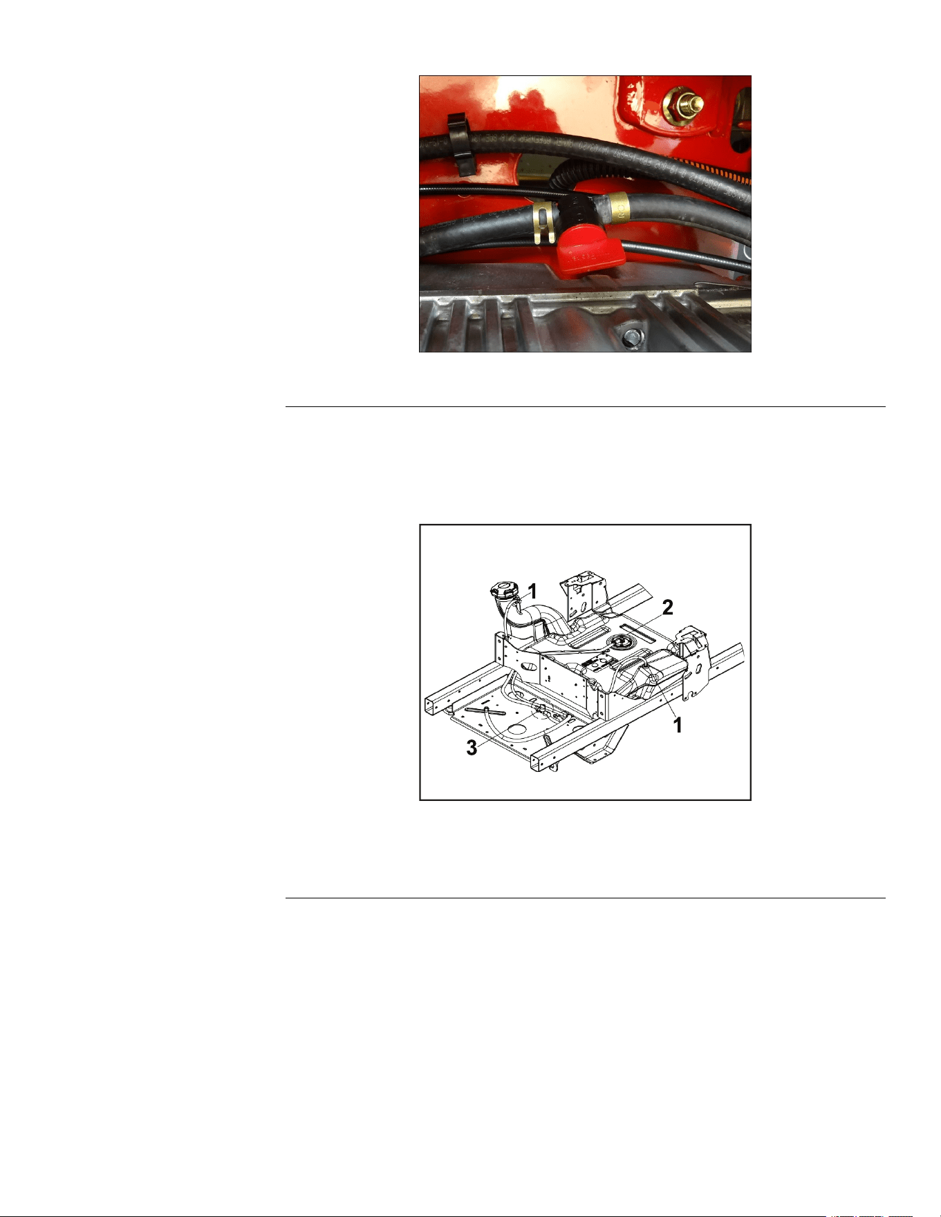
15.Connectthered(B+)wirefromthestarter.
g335895
Figure10
16.Connectthechassiswireharnesstothemainenginewireharness.
TITAN®MaxServiceManual
Page4–7
Engine:ServiceandRepairs
3442-428RevA
EngineInstallation(continued)
g344221
Figure13
20.Fillthecrankcasewithapprovedoilandverifyproperoillevel.
21.Connectthebatterybyinstallingthepositivecablerst,thenthenegative
cabletothebattery.
22.Verifytheproperfunctionoftheunit.
23.VerifytheengineRPMissetto3600±100.
TITAN®MaxServiceManual
Page4–9
Engine:ServiceandRepairs
3442-428RevA


Chapter5
Chassis
TableofContents
GeneralInformation..............................................................................................................................5–2
ServiceandRepairs.............................................................................................................................5–3
CasterAssemblyandBearingReplacement......................................................................................5–8
CasterWheelService......................................................................................................................5–11
LeftConsoleReplacement...............................................................................................................5–13
RightConsoleReplacement............................................................................................................5–16
SeatReplacement...........................................................................................................................5–19
FuelT ankReplacement...................................................................................................................5–22
RollOverProtectionSystem(ROPS)Replacement.........................................................................5–24
ThrottleCableAssemblyReplacement............................................................................................5–26
ChokeControlAssemblyReplacement............................................................................................5–29
ParkBrakeHandleAssemblyReplacement.....................................................................................5–30
MotionControlAssemblyReplacement...........................................................................................5–31
TITAN®MaxServiceManual
Page5–1
Chassis
3442-428RevA

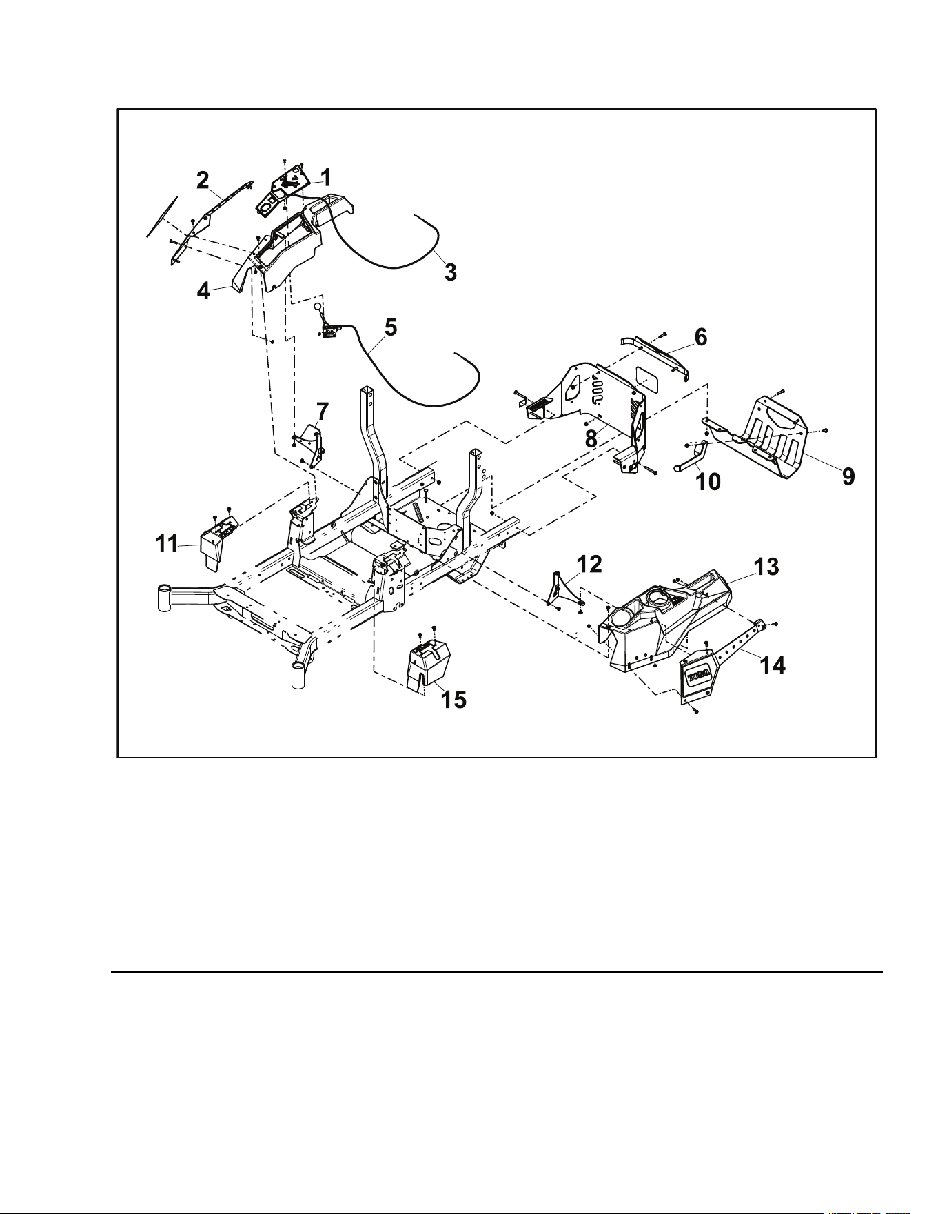
ServiceandRepairs
ChassisAssembly1
g341890
Figure14
1.ControlPanelAssembly9.MuferGuard
2.RHPodCover10.MuferGuardBracket
3.ChokeControlCable11.RHMotionControlCover
4.RHConsole12.LHConsoleBracket
5.ThrottleControlCable13.LHConsole
6.UpperRearTrim
14.LHCover
7.RHConsoleSupport15.LHMotionControlCover
8.RearGuardAssembly
TITAN®MaxServiceManual
Page5–3
Chassis:ServiceandRepairs
3442-428RevA
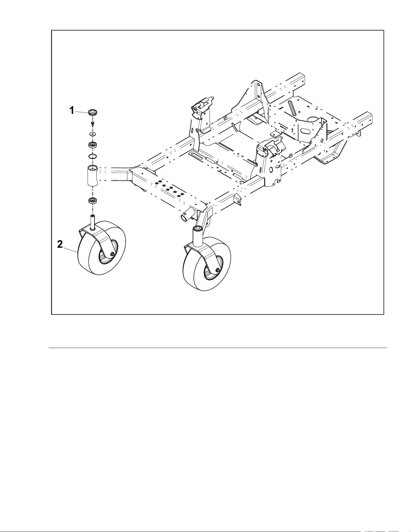
CasterAssemblyandBearingReplacement
CasterAssemblyandBearingRemoval
1.ParkthemachineonalevelsurfaceanddisengagethePTO.Stoptheengine,
waitforallmovingpartstostop,andremovekey.Engagetheparkingbrake.
2.Disconnectthebatterybyremovingthenegativecablerst,thenthepositive
cablefromthebattery.
3.Raiseandsupporttheunitsothatthefrontwheelsareofftheground,block
rearwheels.
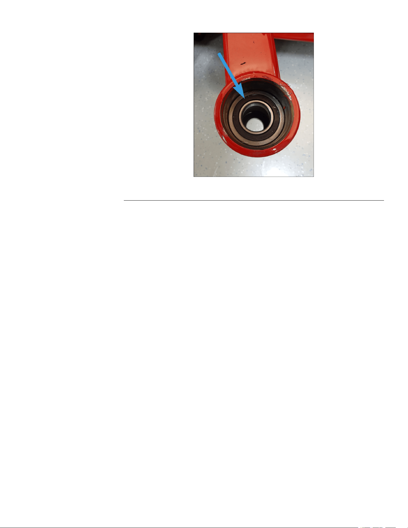
4.Usingahammerandatheadscrewdriver,removethegreasecap.
g342953
Figure19
5.Supporttheundersideofthecasterfork,andremovethe(0.313-18NCx
0.750inch)screwandwashersecuringthecasterforktotheframe.
g342955
Figure20
6.Removethecasterforkfromthemainframe.Inspectthecasterforkshaft
forwearordamage.
7.Usingapunchandhammer,removetheupperandlowerbearingsfrom
theaxle.
Chassis:ServiceandRepairs
Page5–8
TITAN®MaxServiceManual
3442-428RevA
CasterAssemblyandBearingRemoval(continued)
g342956
Figure21
8.Inspectthe2bearingsforwearordamage.Replaceifnecessary.
9.Inspecttheinsideoftheaxlebearingareafordamageorexcessivewear.
CasterAssemblyandBearingInstallation
1.Cleanthesurfaceinsidetheaxlebearingarea,keepingsurfacecleanof
debris.
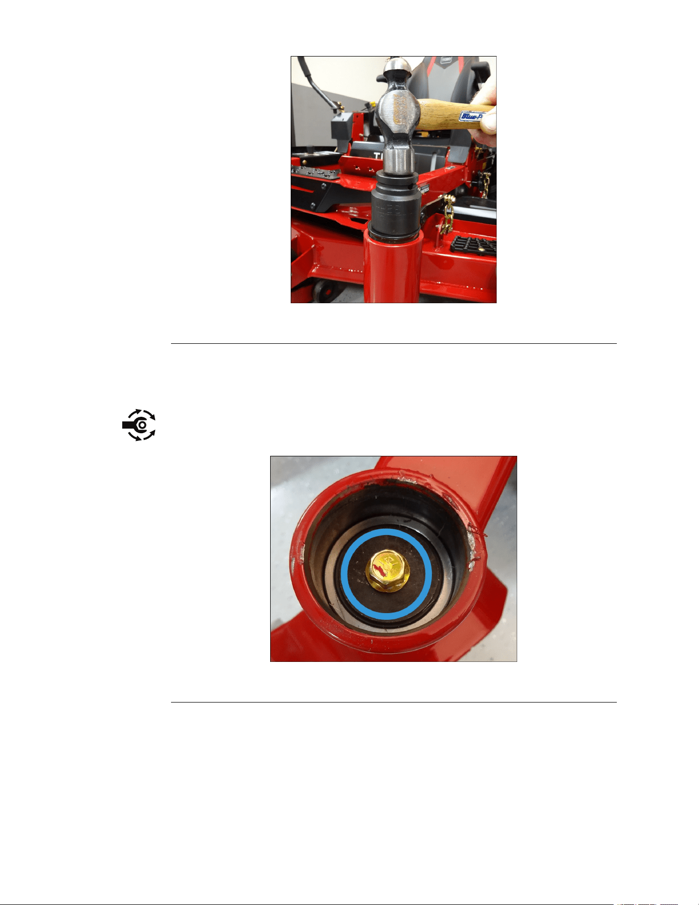
2.Usinga(32mm)socketandahammer,installthelowerbearingfromthe
bottomsideintotheaxle.Verifythebearingisfullyseated.
Note:Thebearingsaresealedanddonotrequiregrease/lubrication.
3.Usinga(32mm)socketandahammer,installtheupperbearingfromthe
bottomsideintotheaxle.Verifythebearingisfullyseated.
Note:Thebearingsaresealedanddonotrequiregrease/lubrication.
TITAN®MaxServiceManual
Page5–9
Chassis:ServiceandRepairs
3442-428RevA
CasterAssemblyandBearingInstallation(continued)
g342957
Figure22
4.Applyanti-seizetoforkshaftbeforeinstalling.
5.Installthecasterfromthebottomsideoftheframeandplaceatwasher
ontopofthebearing.
6.Installthe(0.313-18NCx0.750inch)screwandtightentothecastershaft.
Torquethescrewto22.597±2.82N•m(200±25in-lb).
g342955
Figure23
7.Usinga(32mm)socketandahammer,installthegreasecapontotheframe.
Note:Replacethegreasecapifdamaged.
8.Connectthebatterybyinstallingthepositivecablerst,thenthenegative
cabletothebattery.
9.Lowertheunitandverifyproperfunction.
Chassis:ServiceandRepairs
Page5–10
TITAN®MaxServiceManual
3442-428RevA
CasterWheelService
CasterWheelDisassembly
1.ParkthemachineonalevelsurfaceanddisengagethePTO.Stoptheengine,
waitforallmovingpartstostop,andremovekey.Engagetheparkingbrake.
2.Disconnectthebatterybyremovingthenegativecablerst,thenthepositive
cablefromthebattery.
3.Raiseandsupporttheunitsothatthefrontwheelsareofftheground,block
rearwheels.
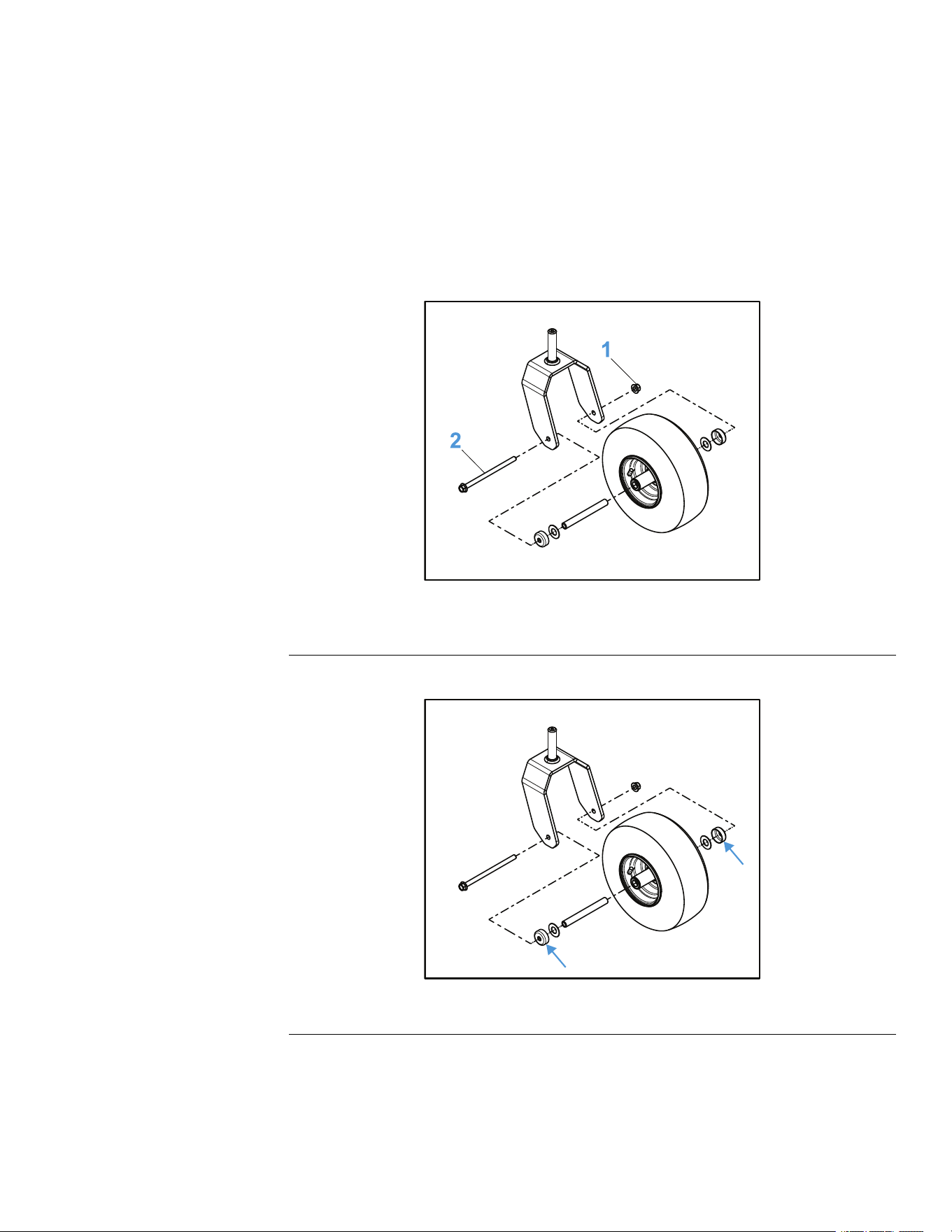
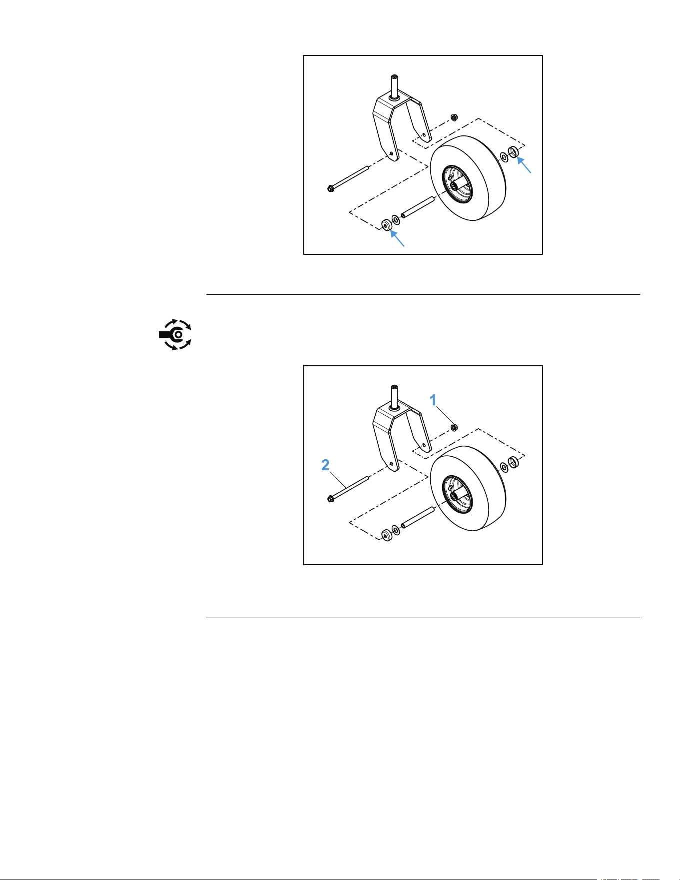
4.Removethe(0.50-13inch)nutand(1/2–13x8.38inch)screwsecuring
thecasterwheeltothecasterfork.
g342888
Figure24
1.Nut
2.Screw
5.Removethe2sealguardsandwashersfromthewheelhub.
g342889
Figure25
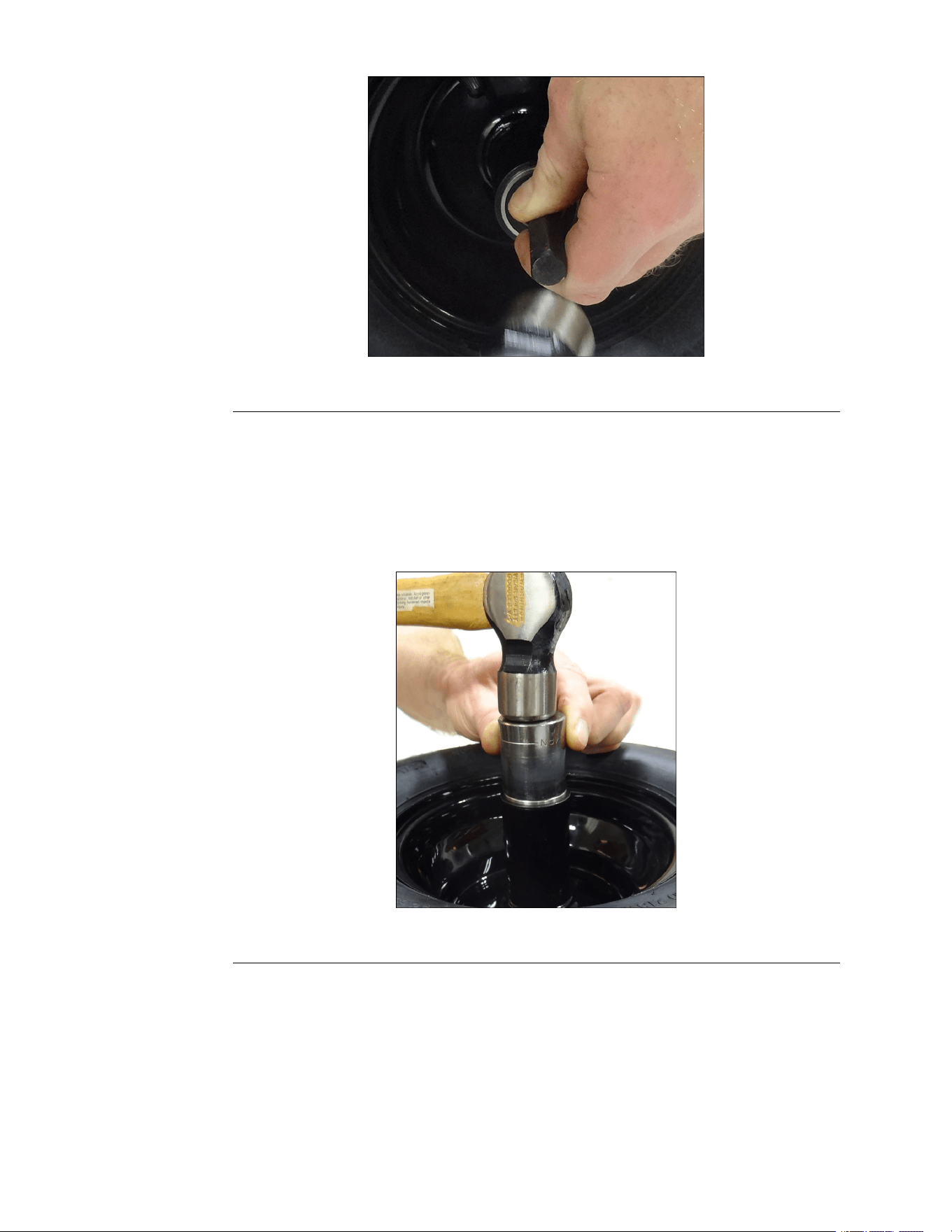
6.Removethecasterwheelspannerfromthebearings.
7.Usingapunchandahammer,removethe2bearingsfromthecasterwheel.
TITAN®MaxServiceManual
Page5–11
Chassis:ServiceandRepairs
3442-428RevA
CasterWheelDisassembly(continued)
g342890
Figure26
8.Inspectthebearingsforwearordamageandreplaceifnecessary.
CasterWheelAssembly
1.Ensurethatthewheeliscleanandfreeofdebrisorexcessivewear.
2.Usinga(11/6inch)socketandhammer,installthe2bearingsintothecaster
wheel.
g342921
Figure27
3.Installthecasterwheelspannerintothecasterwheel.
4.Installthe2sealguardsandwashersontothecasterwheelhubs.
Chassis:ServiceandRepairs
Page5–12
TITAN®MaxServiceManual
3442-428RevA
CasterWheelAssembly(continued)
g342889
Figure28
5.Assemblethecasterwheelontothecasterfork.
6.Installthe(1/2–13x8.38inch)screwand(0.50-13inch)nutsecuringthe
wheeltothecasterfork.Torquethescrewto8.47±0.90N•m(75±8in-lb).
g342888
Figure29
1.Nut
2.Screw
7.Lowertheunitandverifyproperfunction.
8.Connectthebatterybyinstallingthepositivecablerst,thenthenegative
cabletothebattery.
LeftConsoleReplacement
LeftConsoleRemoval
1.ParkthemachineonalevelsurfaceanddisengagethePTO.Stoptheengine,
waitforallmovingpartstostop,andremovekey.Engagetheparkingbrake.
2.Disconnectthebatterybyremovingthenegativecablerst,thenthepositive
cablefromthebattery.
3.Removethebatteryfromthebatterytray.
TITAN®MaxServiceManual
Page5–13
Chassis:ServiceandRepairs
3442-428RevA
LeftConsoleRemoval(continued)
4.Removethe(T30)torxscrewsecuringtheleftconsoletothechassis.
g342987
Figure30
1.TorxScrew
5.Removethe2screws(T30)securingtheleftconsolebrackettothechassis.
g342988
Figure31
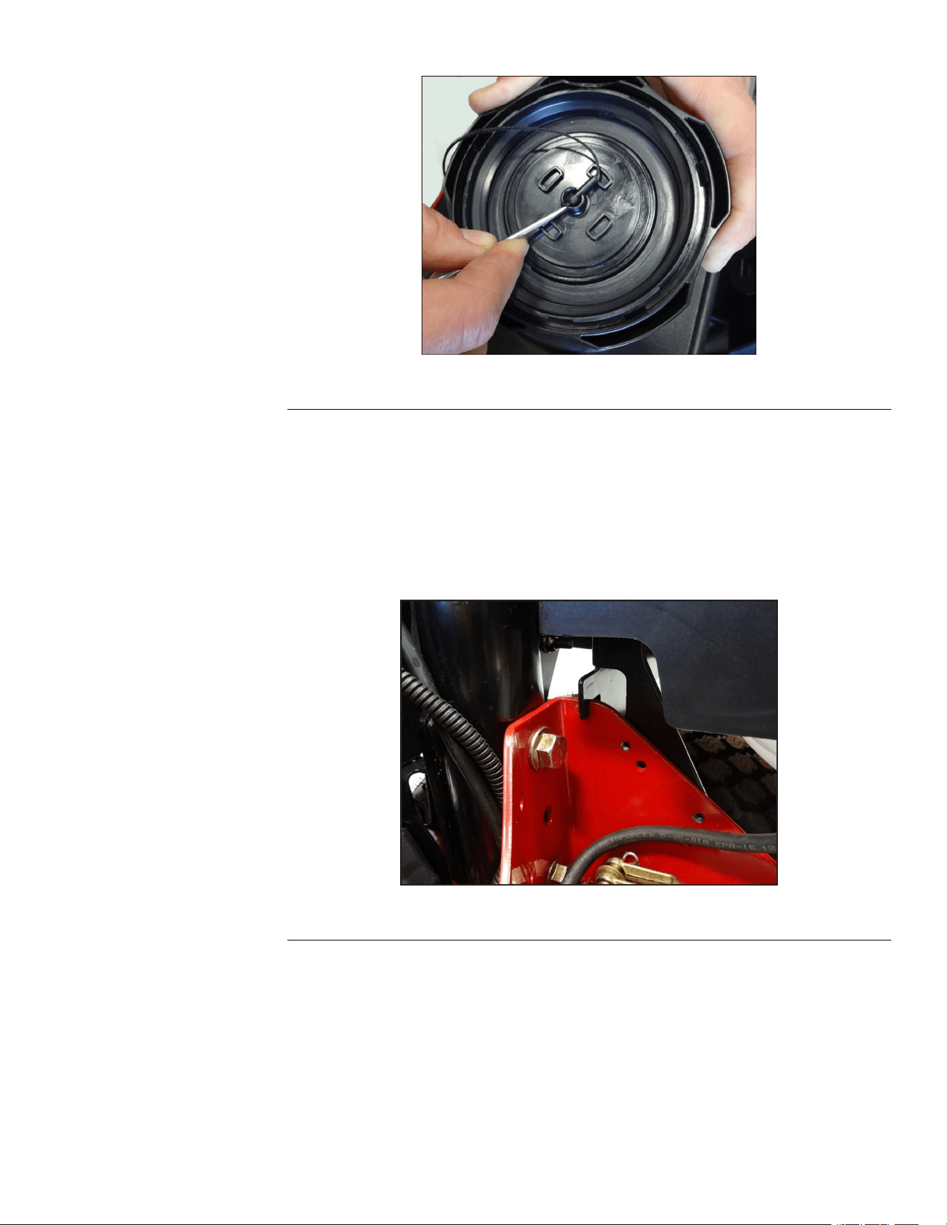
6.Removethefuelcapanddisconnectthekeeperline.
Note:Ensurethekeeperlinedoesnotfallintothefueltank.
Chassis:ServiceandRepairs
Page5–14
TITAN®MaxServiceManual
3442-428RevA
LeftConsoleRemoval(continued)
g342993
Figure32
7.Removetheleftconsolefromthemachine.
8.Replacethefuelcap.
LeftConsoleInstallation
1.Removethefuelcapfromthegastank.
2.Lowertheleftconsoleintoplace.Ensuringtheleftconsoleseatsproperly
onthesupport.
g342994
Figure33
3.Installthekeeperlineintothefuelcap.Installthefuelcap.
4.Installthe2screws(T30)securingtheLHconsolebrackettothechassis.
TITAN®MaxServiceManual
Page5–15
Chassis:ServiceandRepairs
3442-428RevA
LeftConsoleInstallation(continued)
g342988
Figure34
5.Installthe(T30)torxscrewsecuringtheLHconsoletothechassis.
g342987
Figure35
1.TorxScrew
6.Installthebatteryontothebatterytrayandsecurewiththebatterystrap.
7.Connectthebatterybyinstallingthepositivecablerst,thenthenegative
cabletothebattery.
RightConsoleReplacement
RightConsoleRemoval
1.ParkthemachineonalevelsurfaceanddisengagethePTO.Stoptheengine,
waitforallmovingpartstostop,andremovekey.Engagetheparkingbrake.
2.Disconnectthebatterybyremovingthenegativecablerst,thenthepositive
cablefromthebattery.
3.Removethe(T30)torxscrewsecuringtheRHconsoletothechassis.
Chassis:ServiceandRepairs
Page5–16
TITAN®MaxServiceManual
3442-428RevA
RightConsoleRemoval(continued)
g343007
Figure36
4.Removethe2(T25)screwssecuringtheconsoletotheconsolebracketon
theundersideoftheconsole.
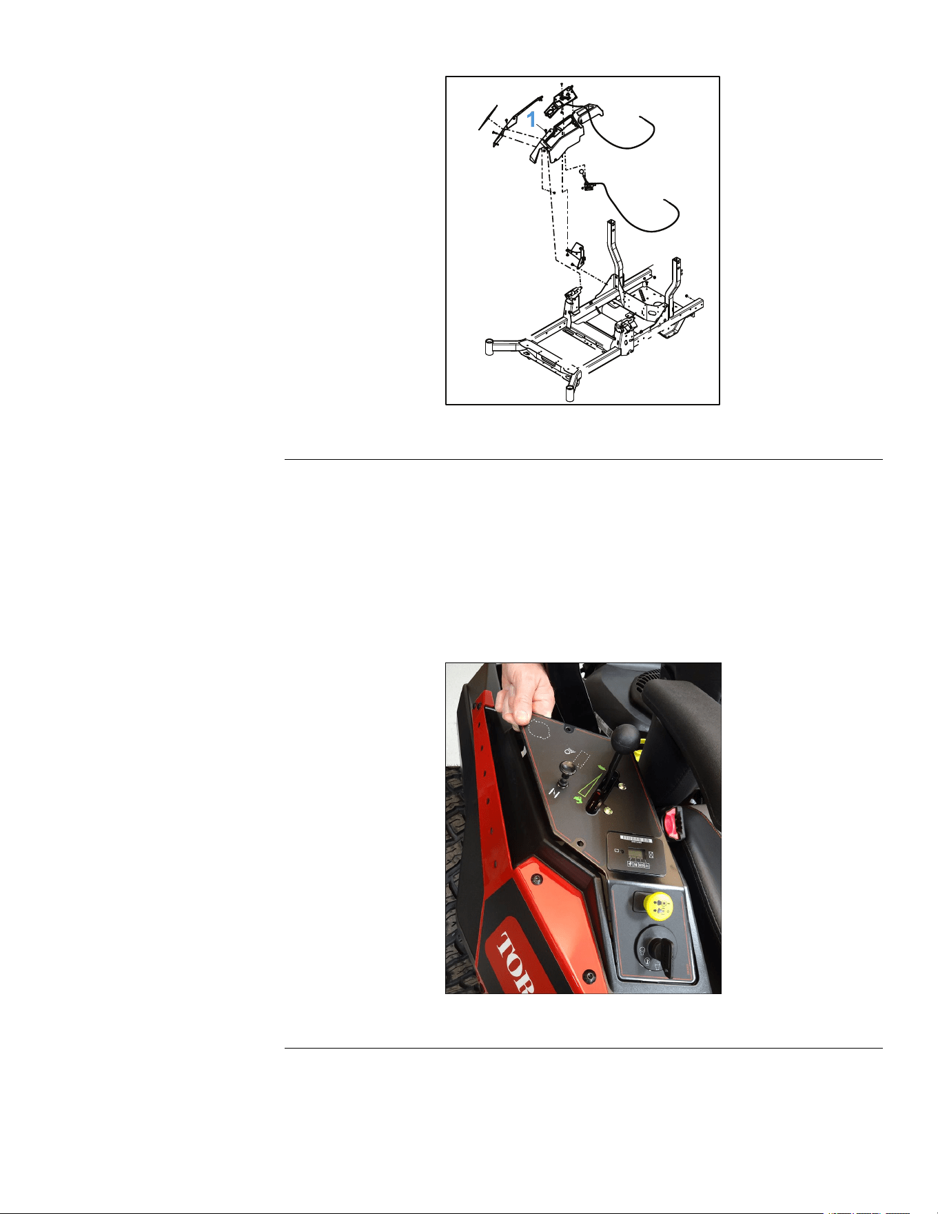
5.Removethe(10–14x1/2inch)plasticscrewsecuringthecontrolpanel
assemblytotheconsole.
6.Lifttheconsoleupwardoffofthemachine,whilefeedingthecontrolpanel
assemblythroughtheopeningintheconsole.
Note:Thecontrolpanelassemblyshouldbesupportedwhileservicingthe
machine,toavoiddamagetocablesorthewireharness.
g344218
Figure37
TITAN®MaxServiceManual
Page5–17
Chassis:ServiceandRepairs
3442-428RevA
RightConsoleInstallation
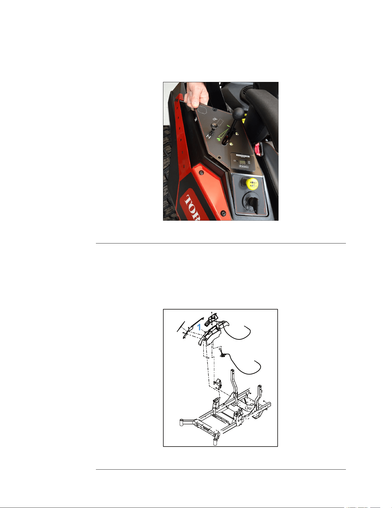
1.Lowertheconsoleintoplace,whilemovingthecontrolpanelassembly
throughtheopeningintheconsoleandintoposition.Verifytheconsole
seatsproperlyonthesupports.
Note:Beforesecuringthecontrolpaneltotheconsole,ensurethatallcables
andelectricalconnectionsareseatedrmlyinplaceontheundersideof
thecontrolpanelassembly.
g344218
Figure38
2.Securethecontrolpanelassemblytotheconsolewithahexscrew.
3.Installthe(10–14x1/2inch)plasticscrewsecuringthecontrolpanel
assemblytotheconsole.
4.Installthe2(T25)screwssecuringtheconsoletotheconsolebracketon
theundersideoftheconsole.
5.Installthe(T30)torxscrewsecuringtheRHconsoletothechassis.
g343007
Figure39
Chassis:ServiceandRepairs
Page5–18
TITAN®MaxServiceManual
3442-428RevA
RightConsoleInstallation(continued)
6.Connectthebatterybyinstallingthepositivecablerst,thenthenegative
cabletothebattery.
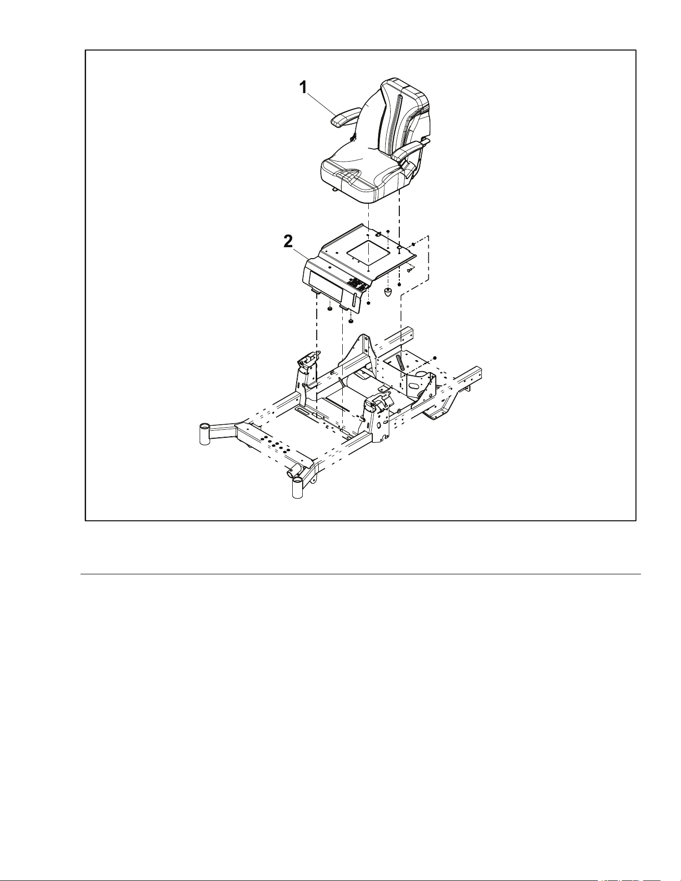
SeatReplacement
SeatRemoval
1.ParkthemachineonalevelsurfaceanddisengagethePTO.Stoptheengine,
waitforallmovingpartstostop,andremovekey.Engagetheparkingbrake.
2.Disconnectthebatterybyremovingthenegativecablerst,thenthepositive
cablefromthebattery.
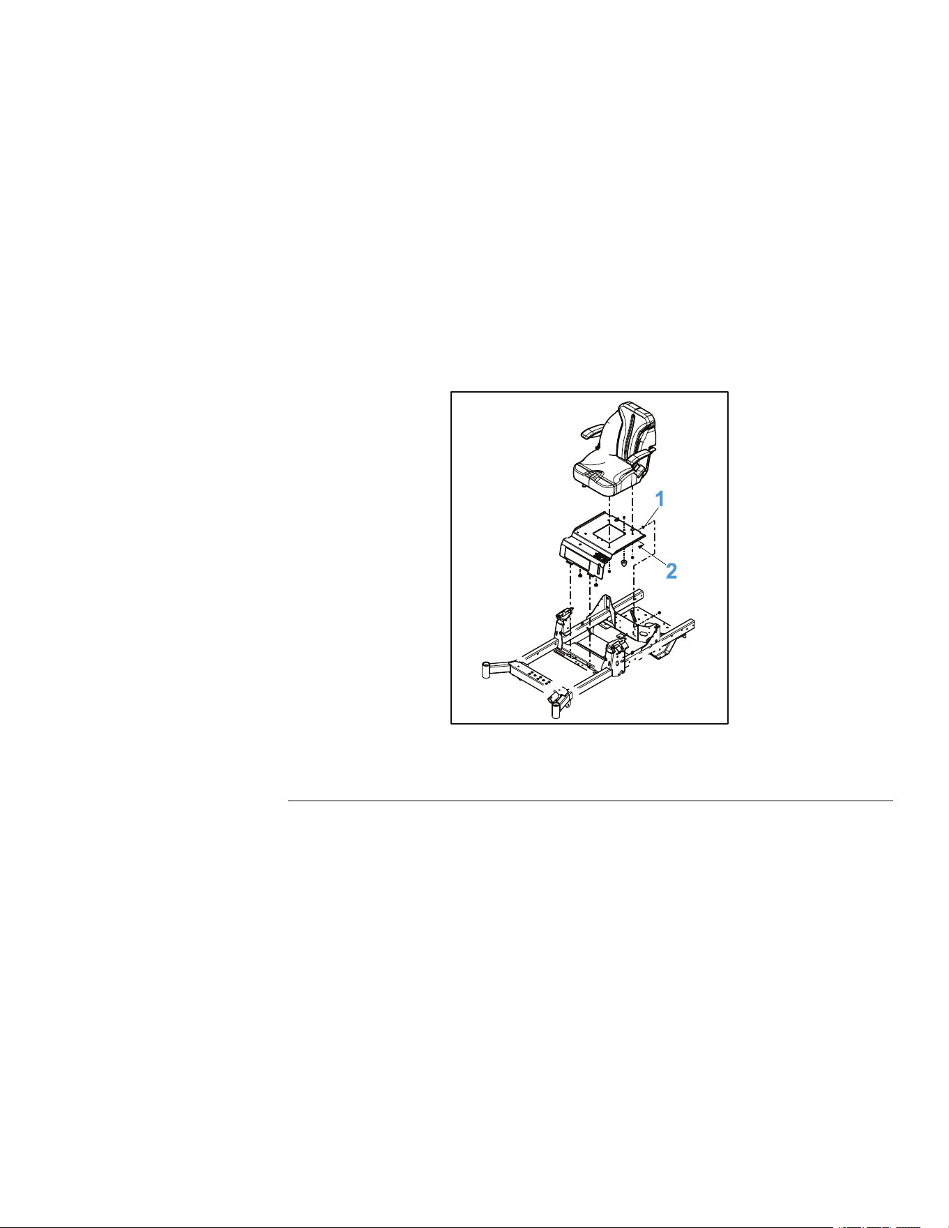
3.Slidetheseatforward.
4.Removethe2(5/16-18inch)nutsand2(0.312-18x1.000inch)carriage
screwssecuringtheseatplatetothechassis.
g344224
Figure40
1.Nut
2.CarriageScrew
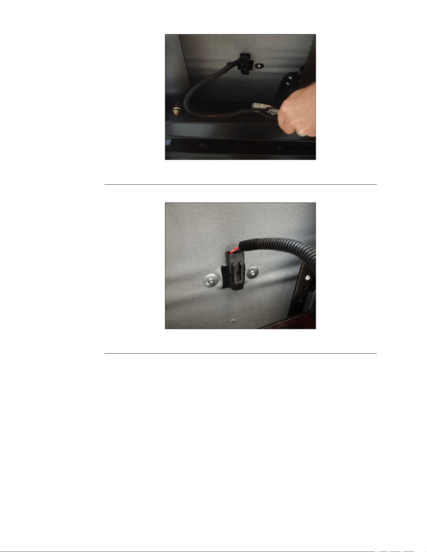
5.Tiptheseatforward,removethe2wireretainersfromthebottomofthe
seatandseatplate.
TITAN®MaxServiceManual
Page5–19
Chassis:ServiceandRepairs
3442-428RevA
SeatInstallation(continued)
g344220
Figure43
3.Installthe2wireretainerstothebottomoftheseatandseatplate.
g344219
Figure44
4.Installthe2(5/16-18inch)nutsand2(0.312-18x1.000inch)carriagescrews
securingtheseatplatetothechassis.T orquethescrewsto22.597±2.82N
•m(200±25in-lb).
TITAN®MaxServiceManual
Page5–21
Chassis:ServiceandRepairs
3442-428RevA
SeatInstallation(continued)
g344224
Figure45
1.Nut
2.CarriageScrew
5.Connectthebatterybyinstallingthepositivecablerst,thenthenegative
cabletothebattery.
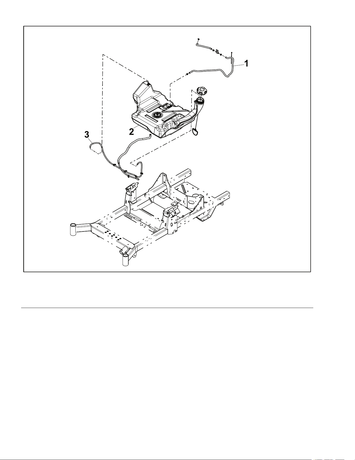
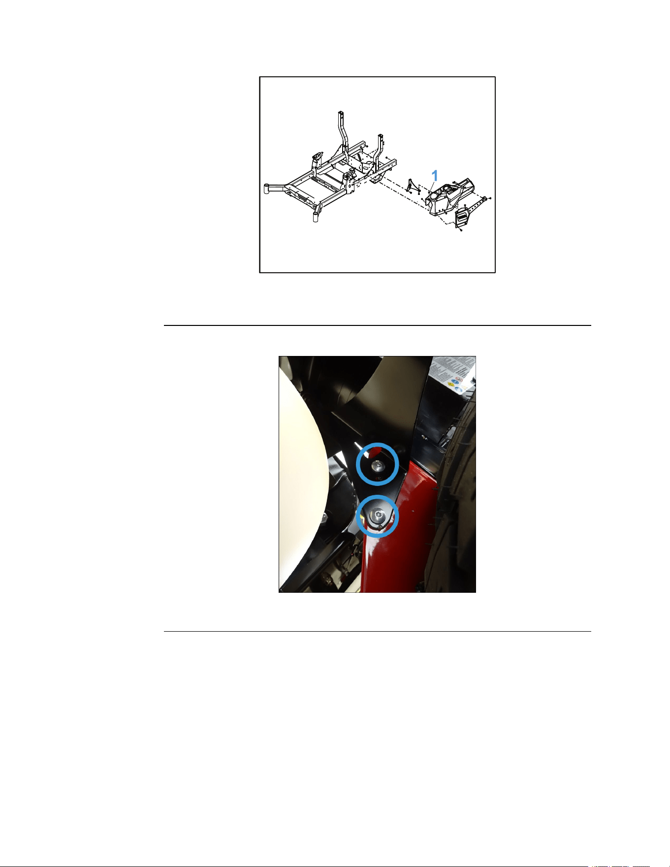
FuelTankReplacement
FuelTankRemoval
Note:Thefuelpick-upsystemisdesignedtopullfuelfromanypartofthetankin
lowfuelsituationsaswellasreducingtheaffectofdebrisinthetank.
g336089
Figure46
1.ParkthemachineonalevelsurfaceanddisengagethePTO.Stoptheengine,
waitforallmovingpartstostop,andremovekey.Engagetheparkingbrake.
2.Disconnectthebatterybyremovingthenegativecablerst,thenthepositive
cablefromthebattery.
3.Closethefuelsupplyvalve.
Chassis:ServiceandRepairs
Page5–22
TITAN®MaxServiceManual
3442-428RevA
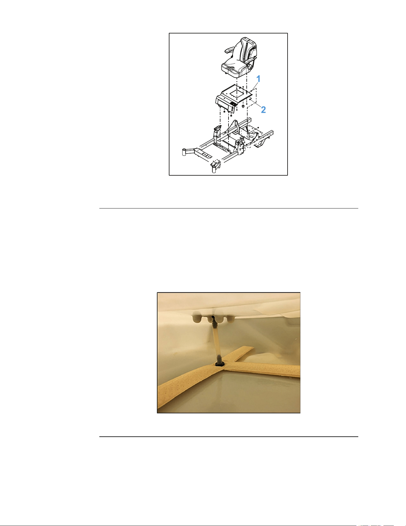
FuelTankRemoval(continued)
g344221
Figure47
4.Removetheleftandrightsconsolesfromthemachine.LeftConsole
Removal(page5–13)RightConsoleRemoval(page5–16)
5.Removetheseatfromthemachine.SeatRemoval(page5–19)
6.Disconnectthefuelsupplylineandthe2ventlinesfromthefueltank.
g336088
Figure48
1.VentHoseAssembly
3.FuelShut-OffValve
2.FuelSupplyLine
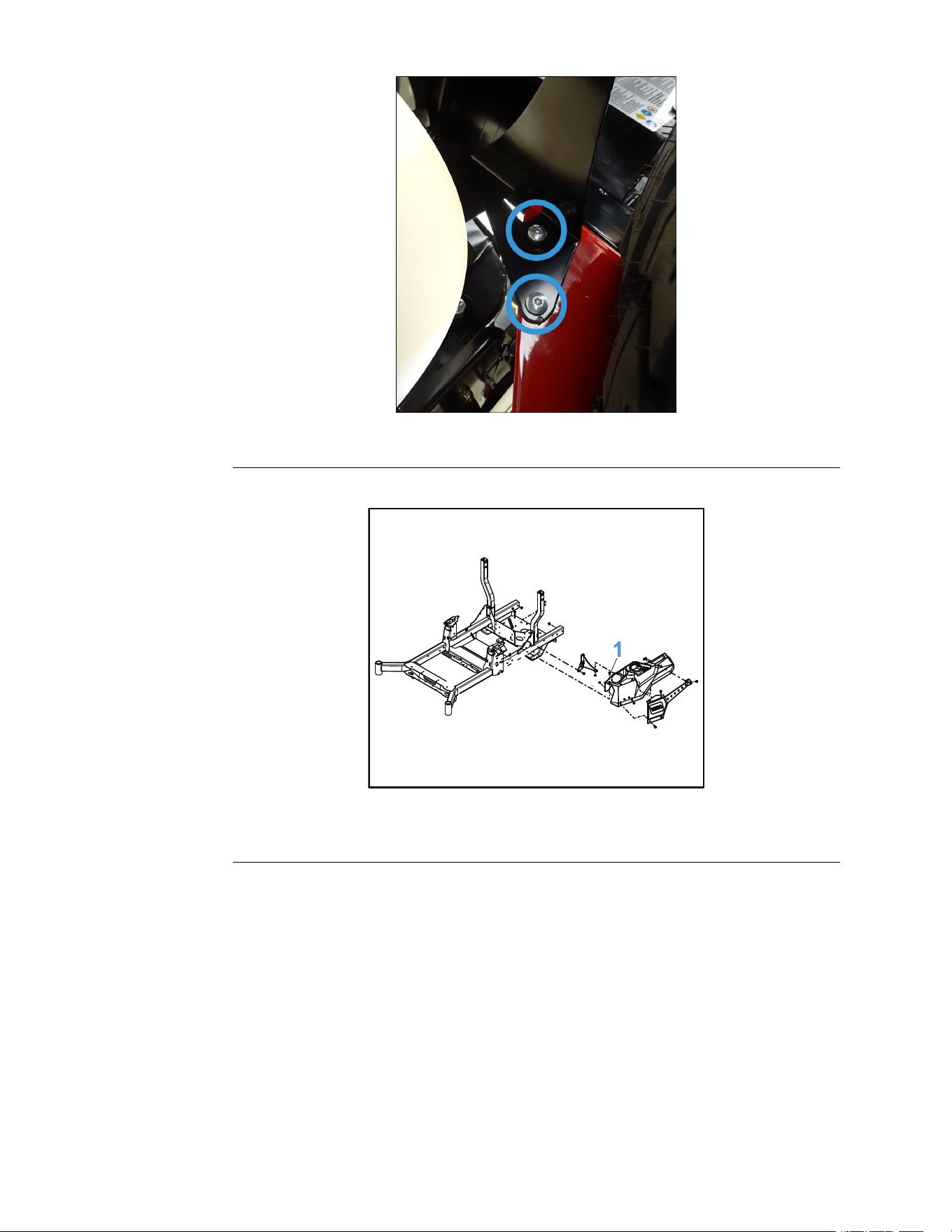
7.Liftthefueltankassemblyfromthemachinebyslidingthetankrearward
andup,awayfromtheframe.
FuelTankInstallation
1.Positionthefueltankassemblyontotheframewiththeventportstowardthe
rearofthemachine.
2.Connectthe2ventlinestothefueltank.
3.Connectthefuelsupplylinetothefueltankandroutethefuellineinthe
detentsmoldedintothetank.
TITAN®MaxServiceManual
Page5–23
Chassis:ServiceandRepairs
3442-428RevA
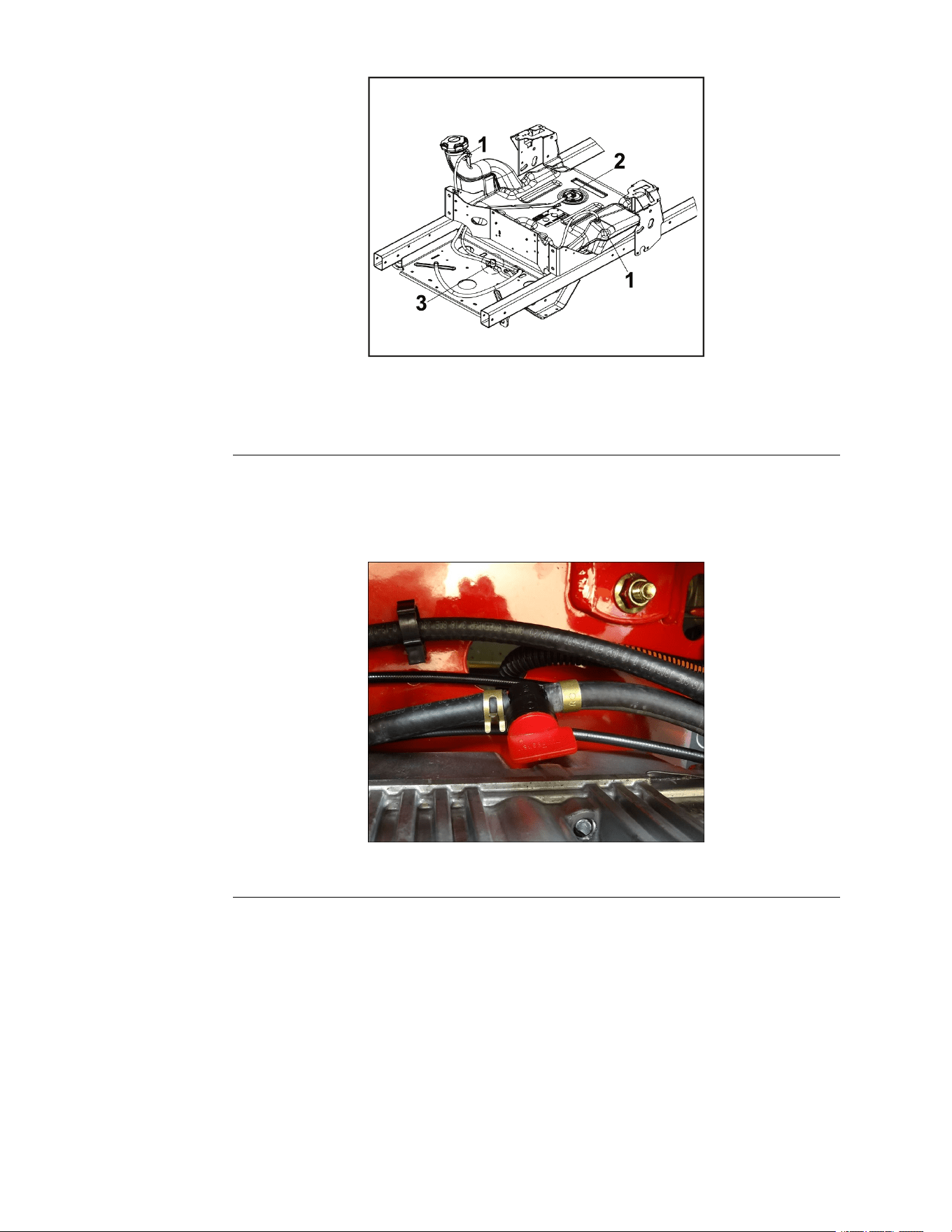
FuelTankInstallation(continued)
g336088
Figure49
1.VentHoseAssembly
3.FuelShut-OffValve
2.FuelSupplyLine
4.Installtheseatontothemachine.SeatInstallation(page5–20)
5.Installtheleftandrightconsoles.LeftConsoleInstallation(page5–15)Right
ConsoleInstallation(page5–18)
6.Openthefuelsupplyvalve.
g344221
Figure50
7.Connectthebatterybyinstallingthepositivecablerst,thenthenegative
cabletothebattery.
RollOverProtectionSystem(ROPS)Replacement
RollOverProtectionSystem(ROPS)Removal
1.ParkthemachineonalevelsurfaceanddisengagethePTO.Stoptheengine,
waitforallmovingpartstostop,andremovekey.Engagetheparkingbrake.
2.Disconnectthebatterybyremovingthenegativecablerst,thenthepositive
cablefromthebattery.
3.FoldtheROPSassemblyintotheuprightpositionandlockinplace.
Chassis:ServiceandRepairs
Page5–24
TITAN®MaxServiceManual
3442-428RevA
RollOverProtectionSystem(ROPS)Removal(continued)
Note:Foreasieraccess,removetheleftandrightsideconsoles.Left
ConsoleRemoval(page5–13)RightConsoleRemoval(page5–16)
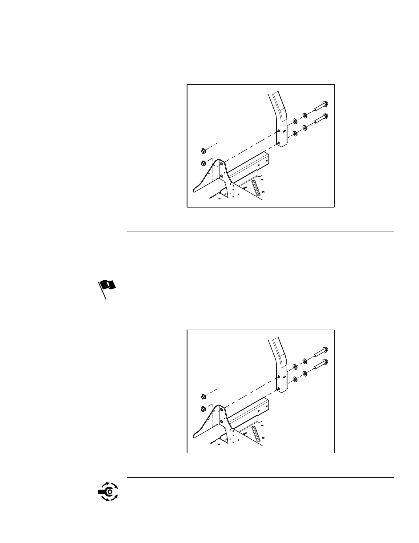
4.SupporttheROPSassemblyandremovethe2screws,4washers,and2
nutssecuringtheLHROPSassemblytothechassis.RepeatontheRH
ROPSassembly.
g344235
Figure51
5.LiftandremovetheROPSassemblyfromthemachine.
RollOverProtectionSystem(ROPS)Installation
1.InstalltheROPSassemblyontothemachine.
2.Installthe2screws,4washers,and4nutssecuringtheLHROPSassembly
tothechassis.RepeatontheRHROPSassembly.
Note:TheorientationoftheROPShardwareiscritical.Verifythescrews
areorientatedcorrectly.
g344235
Figure52
TITAN®MaxServiceManual
Page5–25
Chassis:ServiceandRepairs
3442-428RevA
RollOverProtectionSystem(ROPS)Installation(continued)
3.TorquetheROPSconnectinghardwareto122–135.58N•m(90–100ft-lb).
4.Iftheleftandrightconsoleswereremoved,installtheleftandrightconsoles.
LeftConsoleInstallation(page5–15)RightConsoleInstallation(page5–18)
5.Connectthebatterybyinstallingthepositivecablerst,thenthenegative
cabletothebattery.
ThrottleCableAssemblyReplacement
ThrottleCableAssemblyRemoval
1.ParkthemachineonalevelsurfaceanddisengagethePTO.Stoptheengine,
waitforallmovingpartstostop,andremovekey.Engagetheparkingbrake.
2.Disconnectthebatterybyremovingthenegativecablerst,thenthepositive
cablefromthebattery.
3.Removethecontrolpanelassemblyfromtherightconsole.RightConsole
Removal(page5–16)
4.Removetheknobfromthethrottlelever.
g336055
Figure53
5.Removethe2(10-24x1/2inch)screwsand2(10-24inch)nutssecuringthe
throttlecontrolassemblytothecontrolpanelassembly.
6.Removethe4(5/16-18x23/4inch)torxscrews,4(5/16-18inch)nuts,2
(0.312-18x1.000inch)carriagescrews,and2(5/16-18inch)nutssecuring
therearguardtothemainframe.
7.Loosentheclampsecuringthethrottlecabletothethrottleplate.
Chassis:ServiceandRepairs
Page5–26
TITAN®MaxServiceManual
3442-428RevA
ThrottleCableAssemblyRemoval(continued)
g344236
Figure54
8.Removethethrottlecablefromthethrottleplate,notingthepositionofthe
cableintheplate.
9.Pullthethrottlecableassemblythroughtheconsoleandoutofthemachine.
ThrottleCableAssemblyInstallation
1.RoutethethrottlecablethroughtherightconsolebetweentheROPSand
thehydraulicuidreservoir,underthefuelandventlines,andunderthe
electrical.
g336057
Figure55
2.Attachthethrottlecableassemblytothecontrolpanelassemblyusing2
screwsandnuts.
3.Installtheknobonthethrottlelever.
TITAN®MaxServiceManual
Page5–27
Chassis:ServiceandRepairs
3442-428RevA
ThrottleCableAssemblyInstallation(continued)
g336055
Figure56
4.Installthethrottlecablefromthethrottleplate.
5.Movethethrottlecontrollevertotheslowidleposition.
6.Placethez-bendofthethrottlecableinthethrottleplateontheenginein
thepositionpreviouslynoted.
7.Placethecableunderthecableclamp.
8.Tightentheclampsecuringthethrottlecabletothethrottleplate.
g344236
Figure57
9.Installthe4(5/16-18x23/4inch)torxscrews,4(5/16-18inch)nuts,2
(0.312-18x1.000inch)carriagescrews,and2(5/16-18inch)nutssecuring
therearguardtothemainframe.Torqueallfastenersto24.29±3.95N
•m(215±35in-lb).
10.Installthe2(10-24x1/2inch)screwsand2(10-24inch)nutssecuringthe
throttlecableassemblytothecontrolpanelassembly.
11.Installthecontrolpanelassemblyontotherightconsole.RightConsole
Installation(page5–18)
12.Ensurethatthethrottlecontrolleverisintheslowidlepositionandtighten
thecableclamp.
Chassis:ServiceandRepairs
Page5–28
TITAN®MaxServiceManual
3442-428RevA
ThrottleCableAssemblyInstallation(continued)
13.Connectthebatterybyinstallingthepositivecablerst,thenthenegative
cabletothebattery.
14.Verifytheproperfunctionoftheunit.
ChokeControlAssemblyReplacement
ChokeControlAssemblyRemoval
1.ParkthemachineonalevelsurfaceanddisengagethePTO.Stoptheengine,
waitforallmovingpartstostop,andremovekey.Engagetheparkingbrake.
2.Disconnectthebatterybyremovingthenegativecablerst,thenthepositive
cablefromthebattery.
3.Removethe4(5/16-18x23/4inch)torxscrews,4(5/16-18inch)nuts,2
(0.312-18x1.000inch)carriagescrews,and2(5/16-18inch)nutssecuring
therearguardtothemainframe.
4.Loosentheclampsecuringthechokecabletothechokeplateontheengine.
g344320
Figure58
5.Removethechokecablefromtheplate,notingthepositionofthecable
intheplate.
6.Removethecontrolpanelassemblyfromtherightconsole.RightConsole
Removal(page5–16)
7.Onthebottomsideofthecontrolpanelassembly,loosenthejamnut
securingthechokeleverinplace.Removethenutfromthechokecable.
8.Pullthechokecableassemblythroughthecontrolpanelandoutofthe
machine.
ChokeControlAssemblyInstallation
1.RoutethechokecablethroughtherightconsolebetweentheROPSandthe
hydraulicuidreservoir,underthefuelandventlines,andundertheelectrical.
2.Threadthejamnutoverthechokecableuptothecontrolpanelassembly
3.Attachthechokecableassemblytothecontrolpanelwiththejamnut.
4.Installthecontrolpanelassemblyintotherightconsole.RightConsole
Installation(page5–18)
5.Movethechokecontrollevertotheopenposition(down).
TITAN®MaxServiceManual
Page5–29
Chassis:ServiceandRepairs
3442-428RevA
ChokeControlAssemblyInstallation(continued)
6.Placethez-bendofthechokecableinthechokeplateontheenginein
thepositionpreviouslynoted.
7.Placethecableunderthecableclamp.
8.Ensurethatthechokecontrolleverispresseddownfullyandtightenthe
cableclamp.
g344320
Figure59
9.Installtherearguardtothemainframe.
10.Installthe4(5/16-18x23/4inch)torxscrews,4(5/16-18inch)nuts,2
(0.312-18x1.000inch)carriagescrews,and2(5/16-18inch)nutssecuring
therearguardtothemainframe.Torqueallfastenersto24.29±3.95N
•m(215±35in-lb).
11.Connectthebatterybyinstallingthepositivecablerst,thenthenegative
cabletothebattery.
12.Verifytheproperfunctionoftheunit.
ParkBrakeHandleAssemblyReplacement
ParkBrakeHandleAssemblyRemoval
1.ParkthemachineonalevelsurfaceanddisengagethePTO.Stoptheengine,
waitforallmovingpartstostop,andremovekey.Engagetheparkingbrake.
2.Disconnectthebatterybyremovingthenegativecablerst,thenthepositive
cablefromthebattery.
3.Releasetheparkingbrake(parkbrakehandledown).
4.Removetheleftconsole.LeftConsoleRemoval(page5–13)
5.Removethelockingcotterpinsecuringtheupperbrakelinkagetothepark
brakelever.
6.Tocompletelyremovetheupperbrakelinkage,removethelockingcotterpin
fromthebrakeshaftandremovetheclevispin.Thelinkagecannowbe
removedfromtheframeslotforinspection,adjustment,orreplacement.
7.Removethe(0.375-16x1.500inch)screwand(3/8-16inch)angenutfrom
theparkbrakeleverassembly.
Chassis:ServiceandRepairs
Page5–30
TITAN®MaxServiceManual
3442-428RevA
ParkBrakeHandleAssemblyInstallation
1.Connecttheupperbrakelinkagetothebrakeshaft.
2.Withtheparkbrakehandlehardwareorientatedasshown,installthe
(0.375-16x1.500inch)screwand(3/8-16inch)angenut.
3.Withtheparkbrakeshaftindisengagedpositionandtheparkbrakeleverin
thelowerposition,rotatetheupperbrakelinkageuntiltheendalignswiththe
holeintheparkbrakelever.
4.Securewithalockingcotterpin.
5.Cycletheparkbrakelevertoensurethatitlocksintheengagedposition.
6.Installtheleftconsole.LeftConsoleRemoval(page5–13)
7.Connectthebatterybyinstallingthepositivecablerst,thenthenegative
cabletothebattery.
8.Verifytheproperfunctionoftheunit.
MotionControlAssemblyReplacement
MotionControlAssemblyRemoval
1.ParkthemachineonalevelsurfaceanddisengagethePTO.Stoptheengine,
waitforallmovingpartstostop,andremovekey.Engagetheparkingbrake.
2.Disconnectthebatterybyremovingthenegativecablerst,thenthepositive
cablefromthebattery.
3.Removetheleftandrightconsoles.LeftConsoleRemoval(page5–13)
RightConsoleRemoval(page5–16)
4.Raiseandsupporttheunitsothatthefrontwheelsareofftheground,block
rearwheels.
5.Removethe2(3/8-16X1.00inch)screwssecuringthemotioncontrolhandle
tothemotioncontrolassembly.
6.Removethe(5/16-18inch)shoulderscrewsecuringthemotioncontrol
damperfromthemotioncontrolassembly.
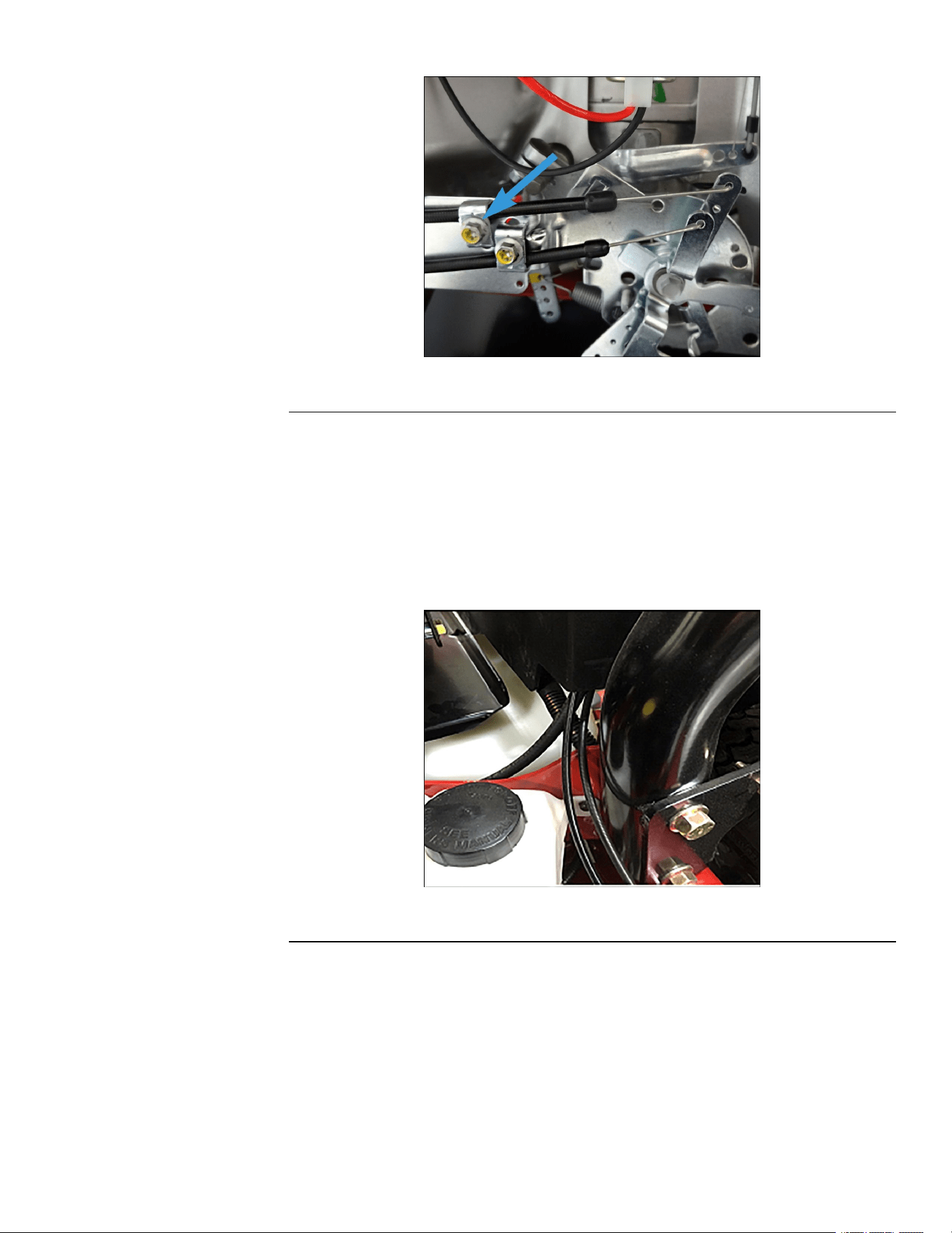
7.Disconnectthemotioncontrollinkagefromthetransmission.
g336043
Figure60
8.Disconnectthemotioncontrolassemblyfromtheframe.
TITAN®MaxServiceManual
Page5–31
Chassis:ServiceandRepairs
3442-428RevA
MotionControlAssemblyRemoval(continued)
g336044
Figure61
9.Lowerthemotioncontrolassemblythroughtheframetowardthecenterof
themachine,removetheassembly.
MotionControlAssemblyInstallation
1.Raiseandsupporttheunitsothatthefrontwheelsareofftheground,block
rearwheels.
2.Positionthemotioncontrolassemblyinplacewiththelinkageextending
towardthetransmission.
3.Securethemotioncontrolassemblytotheframe.
g336044
Figure62
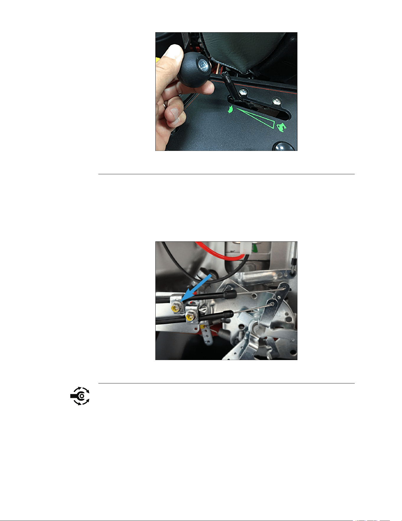
4.Connectthemotioncontrollinkagetothetransmission.
Chassis:ServiceandRepairs
Page5–32
TITAN®MaxServiceManual
3442-428RevA
MotionControlAssemblyInstallation(continued)
g336043
Figure63
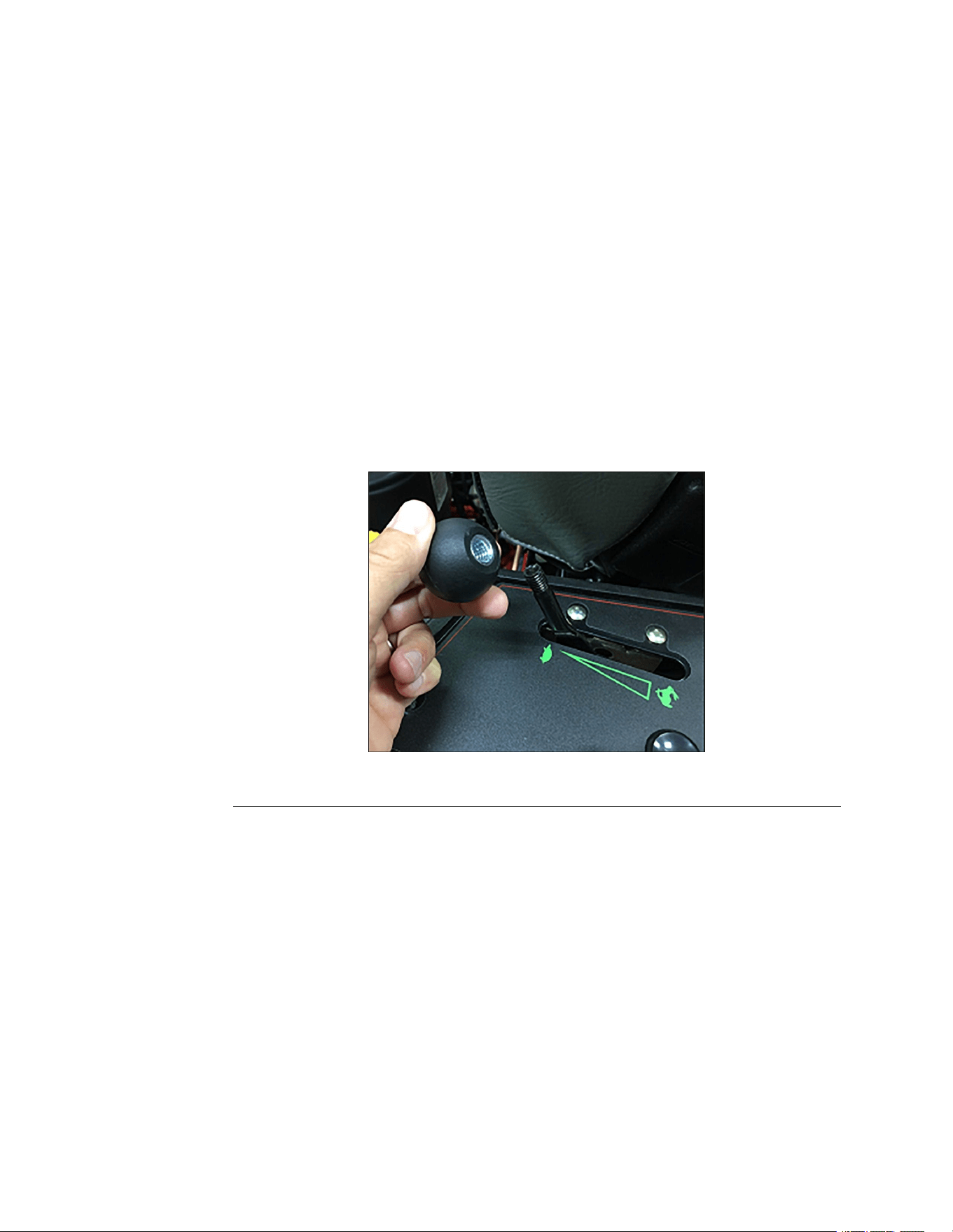
5.Adjustthenutonthemotioncontrolassemblyuntilthemotioncontrolnut
iscenteredinthecontrolplateslot.
6.Installthemotioncontroldampertothemotioncontrolassembly,secure
witha(5/16-18inch)shoulderscrew.T orquethescrewto9.039–11.298
N•m(80-100in-lb).
7.Installthemotioncontrolhandletothemotioncontrolassembly,securewith
2(3/8-16X1.00inch)screws.T orquethescrewto40.67±4.07N•m(30±
3ft-lb).
8.Adjustthemotioncontrollinkages.SeetheproductOperator’sManualfor
themotioncontrollinkageadjustingprocedure.
9.Lowertheunittotheoor.
10.Installtheleftandrightconsoles.LeftConsoleInstallation(page5–15)Right
ConsoleInstallation(page5–18)
11.Connectthebatterybyinstallingthepositivecablerst,thenthenegative
cabletothebattery.
12.Verifytheproperfunctionoftheunit.
13.Adjustthetrackingifnecessary.SeetheproductOperator’sManualforthe
trackingadjustmentprocedure.
TITAN®MaxServiceManual
Page5–33
Chassis:ServiceandRepairs
3442-428RevA


Chapter6
MowerDeck
TableofContents
GeneralInformation..............................................................................................................................6–2
ServiceandRepairs.............................................................................................................................6–3
MowerDeckReplacement.................................................................................................................6–5
DeckDriveBeltReplacement..........................................................................................................6–10
MowerSpindleReplacement...........................................................................................................6–14
BeltT ensionerReplacement............................................................................................................6–17
TITAN®MaxServiceManual
Page6–1
MowerDeck
3442-428RevA

ServiceandRepairs
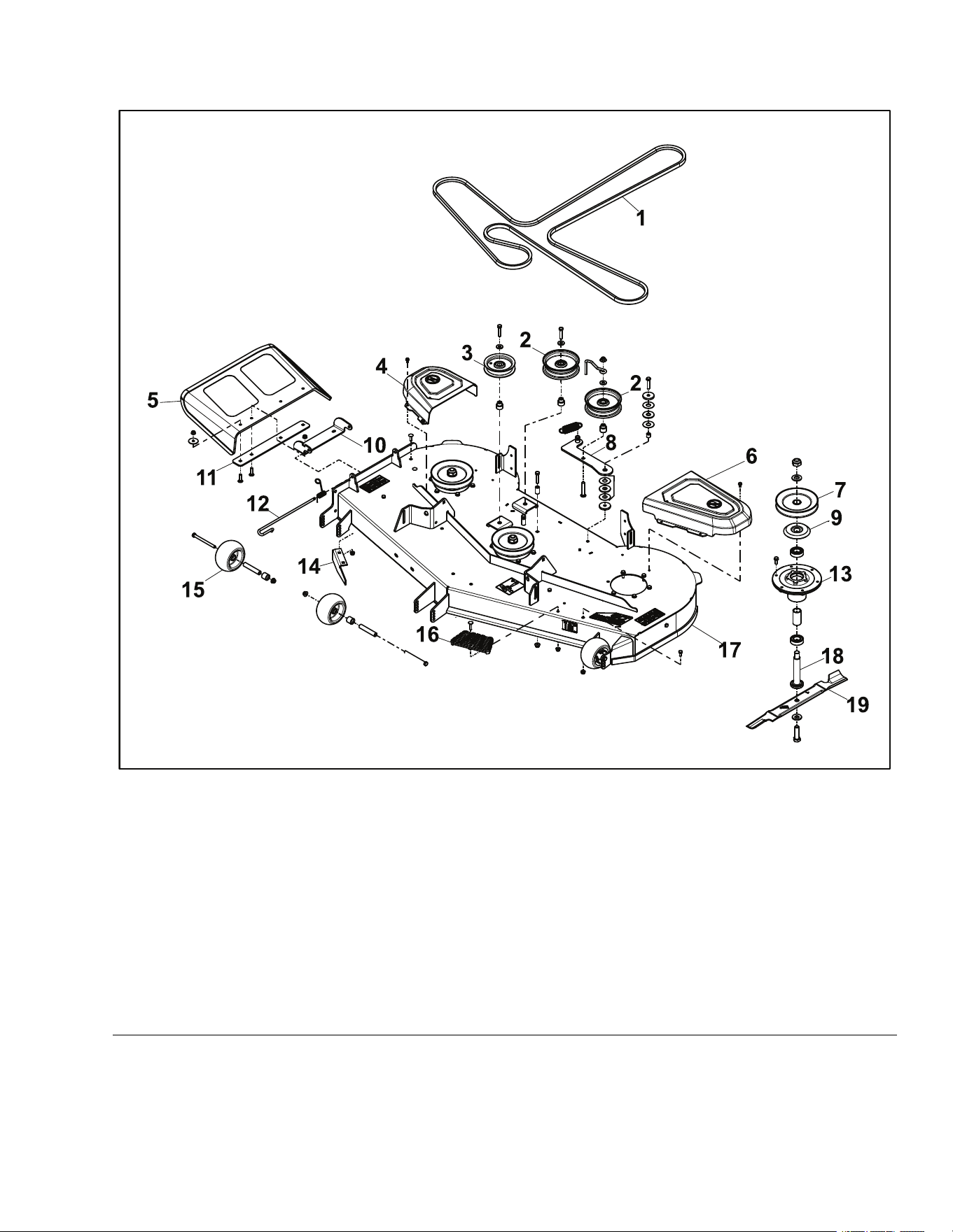
MowerDeckAssembly1
g344576
Figure64
1.DeckDriveBelt
11.DeectorPlate
2.IdlerPulley
12.ChutePin
3.FlatIdlerPulley
13.SpindleAssembly
4.RHBeltCover14.CutoffBafe
5.BearingShield15.AntiScalpRoller
6.LHBeltCover16.DeckStep
7.DriveBladeSheave
17.DeckAssembly
8.IdlerArm
18.SpindleShaft
9.DischargeDeector
19.HiFloBlade
10.UpperDeectorBracket
TITAN®MaxServiceManual
Page6–3
MowerDeck:ServiceandRepairs
3442-428RevA
MowerDeckReplacement
MowerDeckRemoval
1.ParkthemachineonalevelsurfaceanddisengagethePTO.Stoptheengine,
waitforallmovingpartstostop,andremovekey.Engagetheparkingbrake.
2.Disconnectthebatterybyremovingthenegativecablerst,thenthepositive
cablefromthebattery.
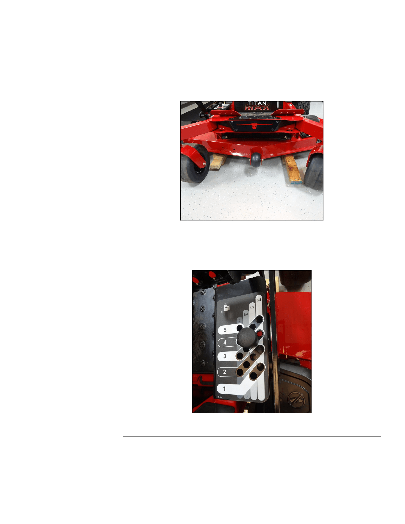
3.Place2(2x4)blocksunderneatheachsideofthemowerdeck.
g344396
Figure66
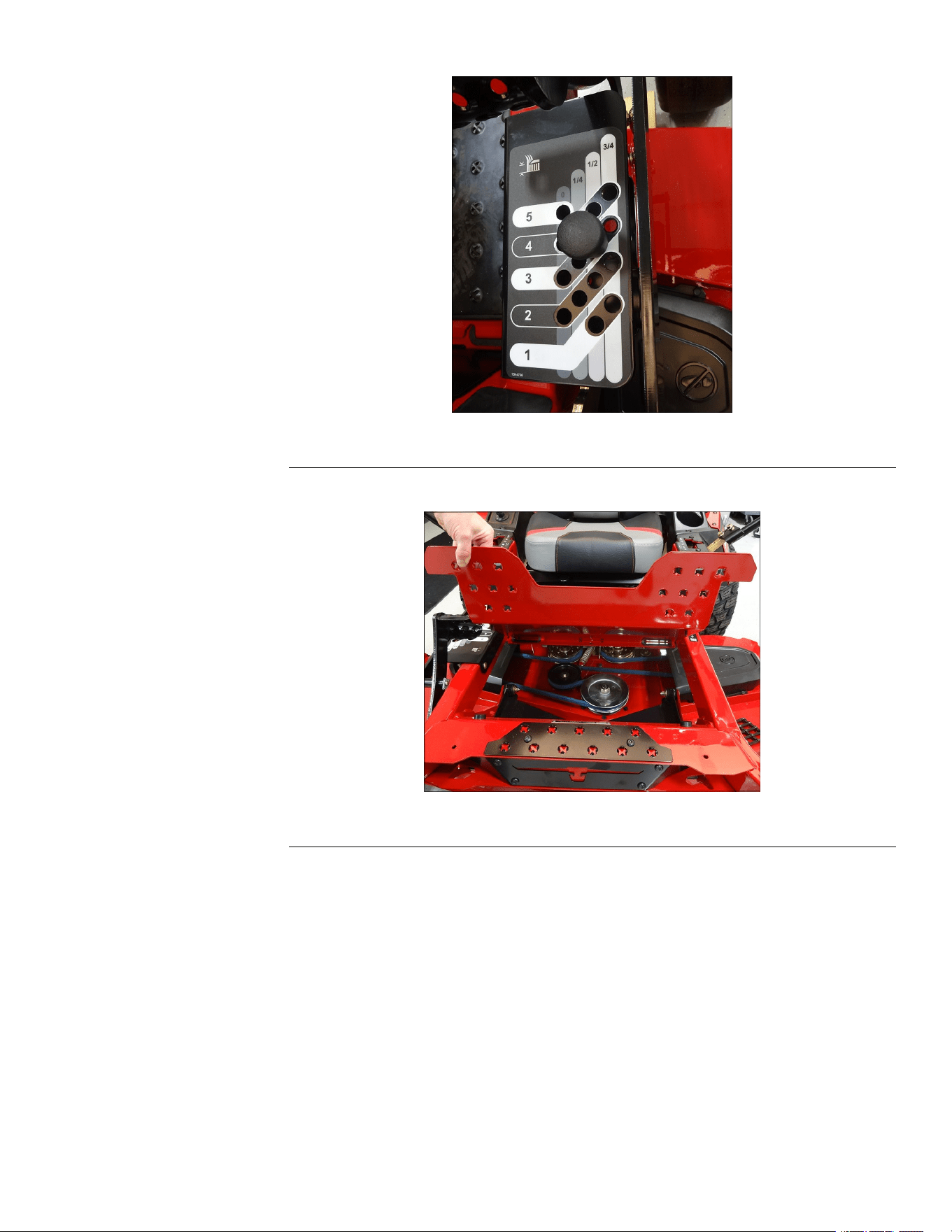
4.Placetheheightofcutpinintothethirdholetolockthemowerdeckinthe
lowestheight-of-cutposition.
g344397
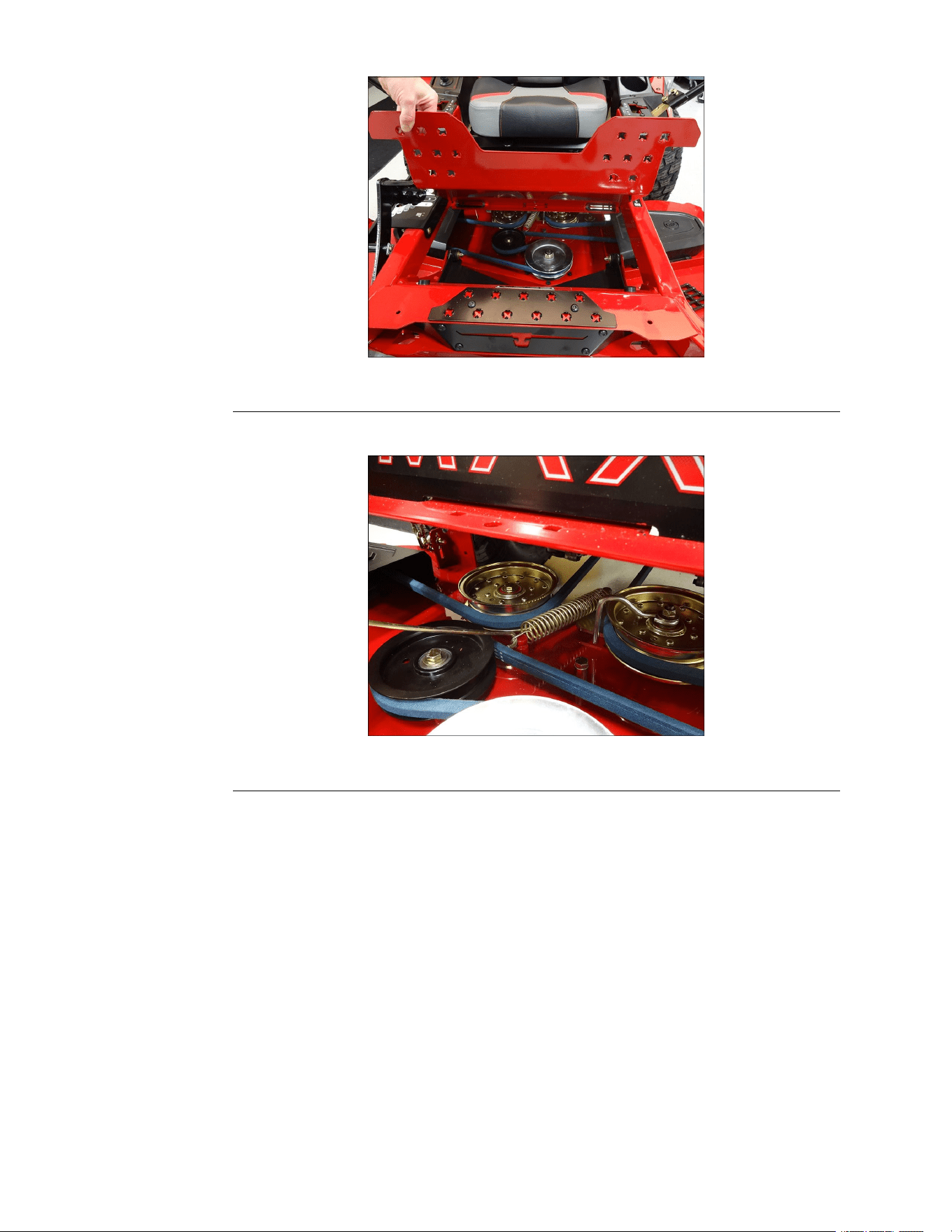
Figure67
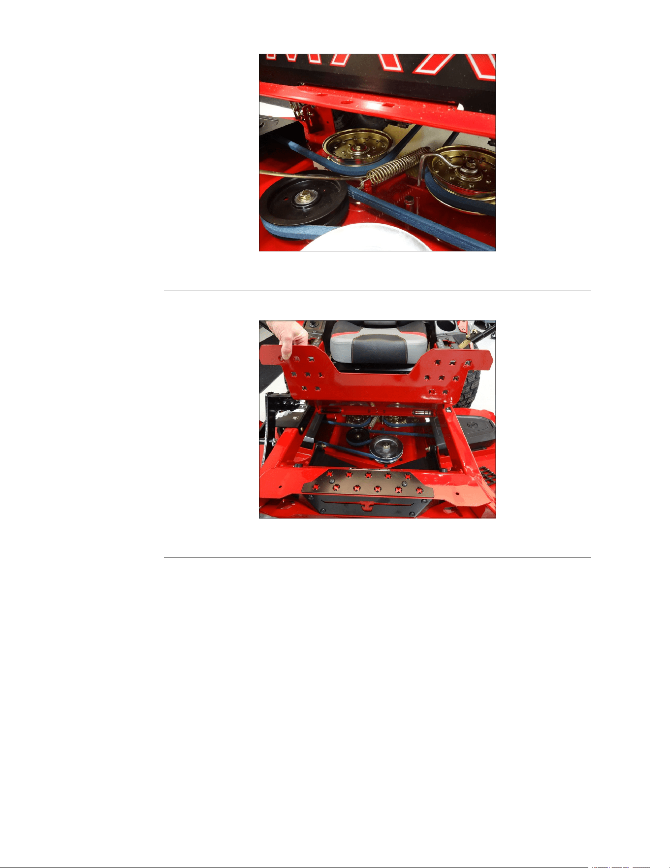
5.Liftandremovetheoorpanfromthemachine.
TITAN®MaxServiceManual
Page6–5
MowerDeck:ServiceandRepairs
3442-428RevA
MowerDeckRemoval(continued)
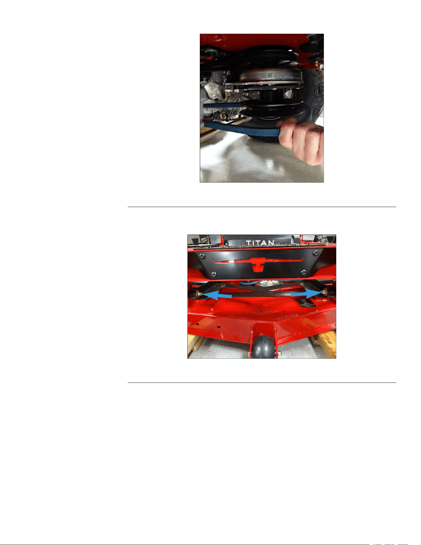
g344400
Figure70
8.Removethe2(0.375-16x2.250inch)carriagescrews,2(3/8-16)nuts,and2
washerssecuringthedeckstrutassemblytotheframe.
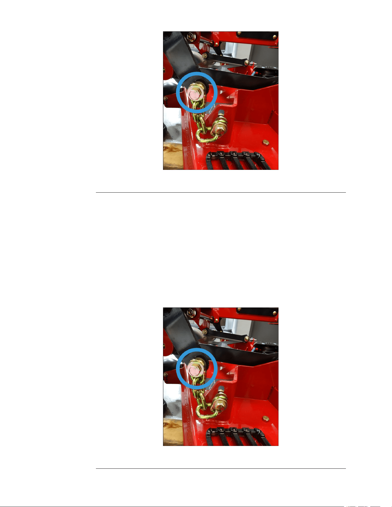
g344401
Figure71
9.Removethe2(3/8inch)LHuppershoulderscrewsand2(3/8-16inch)
washerssecuringthedecksupportchainstothedeckliftshaft.Repeaton
theRHsideofthemachine.
TITAN®MaxServiceManual
Page6–7
MowerDeck:ServiceandRepairs
3442-428RevA
MowerDeckRemoval(continued)
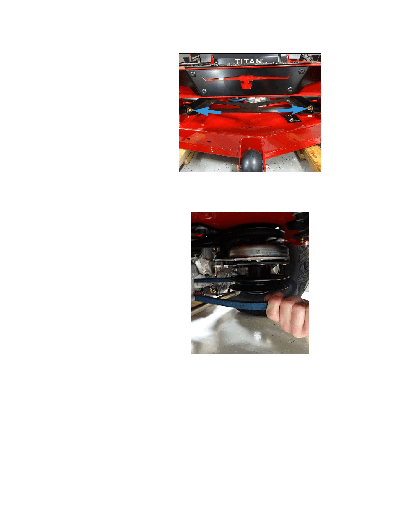
g344402
Figure72
10.Raiseandsupporttheunitsothatthefrontwheelsareofftheground,block
rearwheels.
11.Removethemowerdeck.
MowerDeckInstallation
1.Raiseandsupporttheunitsothatthefrontwheelsareofftheground,block
therearwheels.
2.Placethemowerdeckunderthemachine.
3.Lowertheunittotheoor.
4.Installthe2(3/8inch)LHuppershoulderscrewsand2(3/8-16inch)washers
securingthedecksupportchainstothedeckliftshaft.RepeatontheRH
sideofthemachine.
g344402
Figure73
MowerDeck:ServiceandRepairs
Page6–8
TITAN®MaxServiceManual
3442-428RevA
MowerDeckInstallation(continued)
5.Installthe2(0.375-16x2.250inch)carriagescrews,2(3/8-16)nuts,and2
washerssecuringthedeckstrutassemblytotheframe.
g344401
Figure74
6.InstallthedeckdrivebelttothePTOclutch.
g344400
Figure75
7.Usingaspringremovaltool,installthespringontothemowerdeck.
TITAN®MaxServiceManual
Page6–9
MowerDeck:ServiceandRepairs
3442-428RevA
MowerDeckInstallation(continued)
g344399
Figure76
8.Installtheoorpanontothemachine.
g344398
Figure77
9.Connectthebatterybyinstallingthepositivecablerst,thenthenegative
cabletothebattery.
10.Verifyproperfunctionoftheunit.
DeckDriveBeltReplacement
DeckDriveBeltRemoval
1.ParkthemachineonalevelsurfaceanddisengagethePTO.Stoptheengine,
waitforallmovingpartstostop,andremovekey.Engagetheparkingbrake.
2.Disconnectthebatterybyremovingthenegativecablerst,thenthepositive
cablefromthebattery.
3.Placetheheightofcutpinintothethirdholetolockthemowerdeckinthe
lowestheight-of-cutposition.
MowerDeck:ServiceandRepairs
Page6–10
TITAN®MaxServiceManual
3442-428RevA
DeckDriveBeltRemoval(continued)
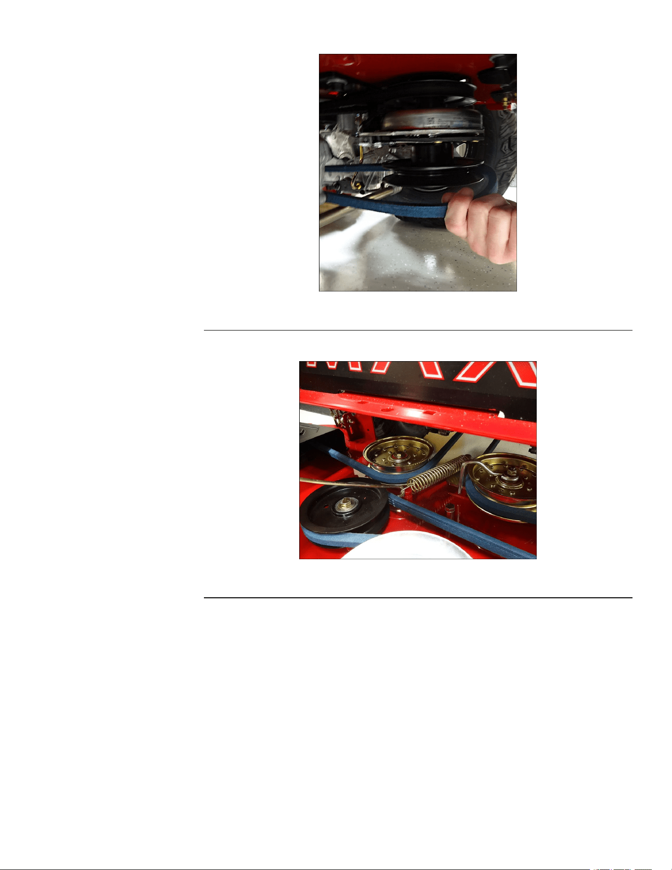
g344399
Figure80
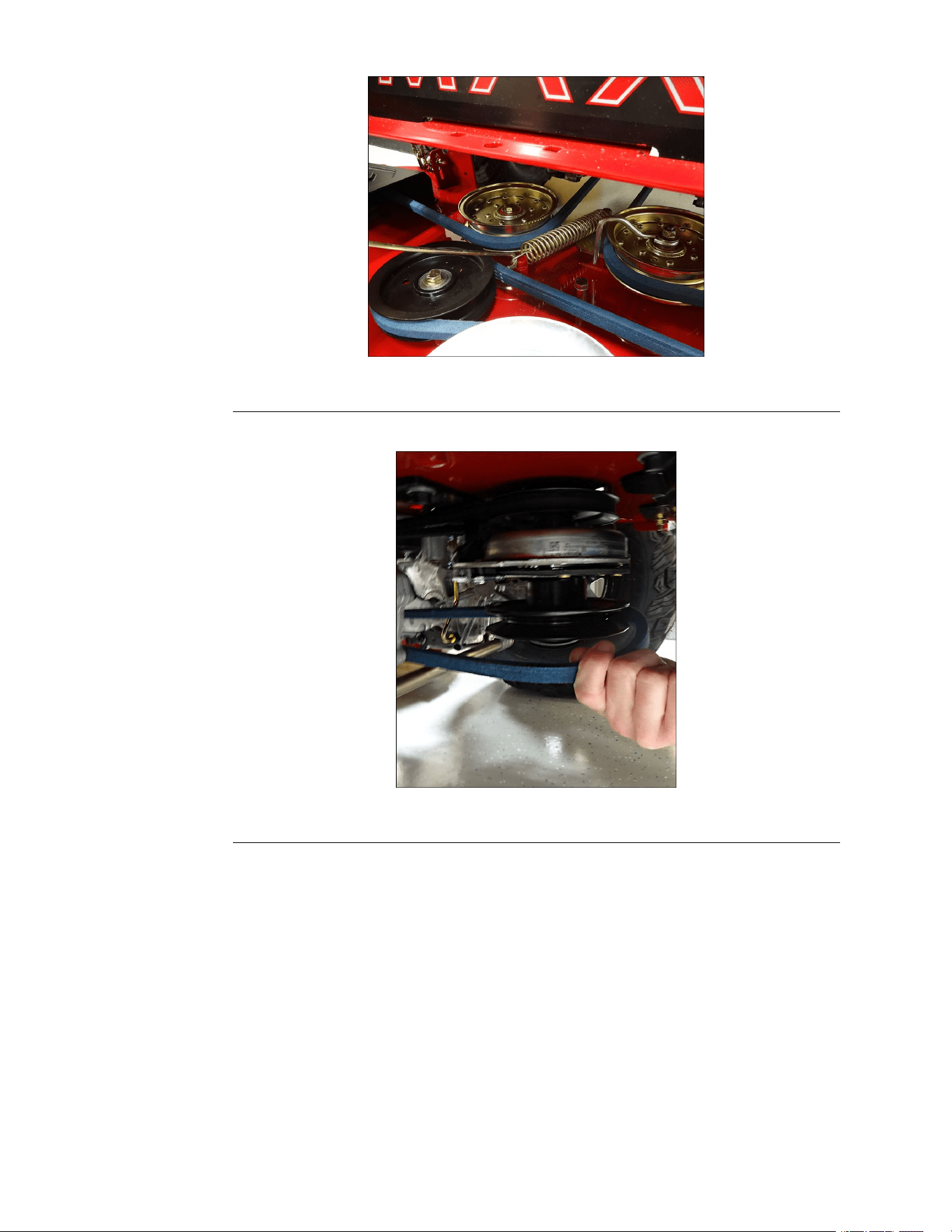
6.RemovethedeckdrivebeltfromthePTOclutch.
g344400
Figure81
7.Removethe4(0.250-20x0.500inch)screwssecuringtheLHbeltcoverto
themowerdeck.RemovetheLHbeltcoverfromthemowerdeck.Repeaton
theRHsideofthemachine.
8.Loosenthe(3/8-16inch)nutsecuringtheidlerpulleytotheidlerarm.
9.Removethedeckdrivebeltfromthemowerdeck.
DeckDriveBeltInstallation
1.Routethedeckdrivebeltaroundthemowerpulleys.
2.Tightenthe(3/8-16inch)nutsecuringtheidlerpulleytotheidlerarm.
3.InstallLHbeltcoverontothemowerdeckandsecurewith4(0.250-20x
0.500inch)screws.RepeatontheRHsideofthemachine.
4.InstallthedeckdrivebelttothePTOclutch.
MowerDeck:ServiceandRepairs
Page6–12
TITAN®MaxServiceManual
3442-428RevA
DeckDriveBeltInstallation(continued)
g344398
Figure84
7.Connectthebatterybyinstallingthepositivecablerst,thenthenegative
cabletothebattery.
8.Verifyproperfunctionoftheunit.
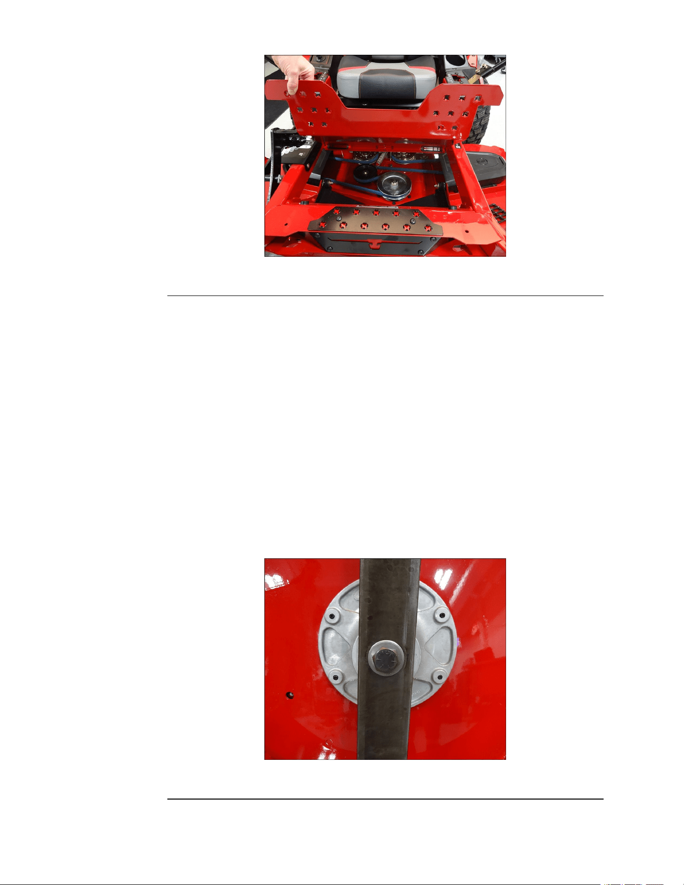
MowerSpindleReplacement
MowerSpindleRemoval
1.Removethemowerdeck.MowerDeckRemoval(page6–5)
2.Removethe4(0.250-20x0.500inch)screwssecuringtheLHbeltcoverto
themowerdeck.RemovetheLHbeltcoverfromthemowerdeck.Repeaton
theRHsideofthemachine.
3.Removethedeckdrivebeltfromthemowerdeck.
4.Raiseandsupportthemowerdeck.
5.Fromtheundersideofthemowerdeck,removethebladescrewandwasher
securingeachmowerbladetothemowerdeck.
g344424
Figure85
6.Lowerthemowerdecktothegroundtoaccessthetopsideofthemowerdeck.
MowerDeck:ServiceandRepairs
Page6–14
TITAN®MaxServiceManual
3442-428RevA
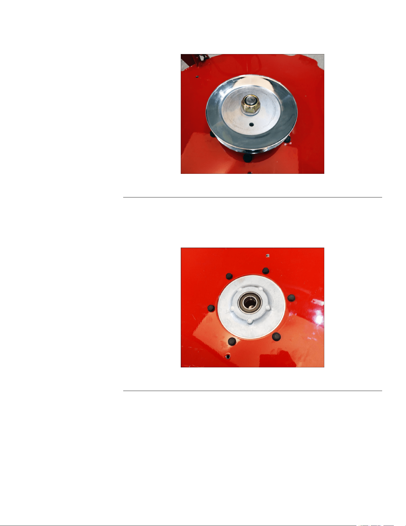
MowerSpindleRemoval(continued)
7.Fromthetopsideofthemowerdeck,removethe(0.750-16inch)spindlelock
nutandwashersecuringtheeachspindleshafttothedrivebladesheaves.
g344425
Figure86
8.Removeeachdrivebladesheaveandspindleshaftfromthemowerdeck.
9.Removethebearingshields.
10.Removeanddiscardthe6(5.16-18x7/8inch)taptitescrewssecuring
spindleassembliestothemowerdeck.
g344426
Figure87
11.Removethespindleassembliesfromthemowerdeck.
12.Usingahammerandapunch,removethe2bearingsandspacersfrom
eachspindleassembly.
MowerSpindleInstallation
1.Usinga(32mm)socketandahammer,installthetopbearingsintothe
spindles.
TITAN®MaxServiceManual
Page6–15
MowerDeck:ServiceandRepairs
3442-428RevA
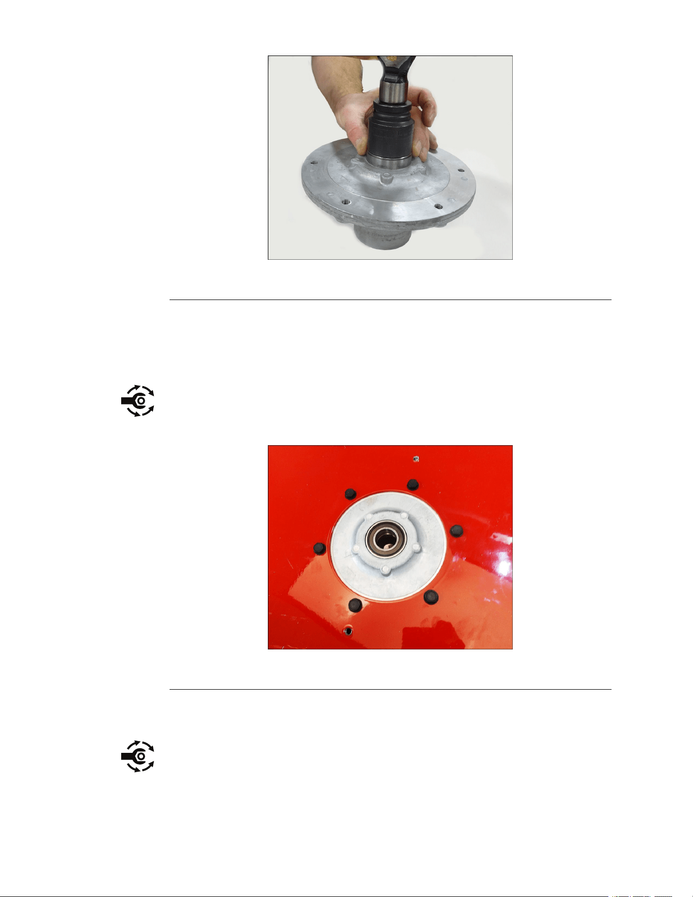
MowerSpindleInstallation(continued)
g344427
Figure88
2.Installthespacersintothebottomofthespindles.
3.Usinga(32mm)socketandahammer,installthebottombearingsintothe
spindles.
4.Installthespindleassembliesintothemowerdeck.
5.Installthe6(5.16-18x7/8inch)newtaptitescrewssecuringspindle
assembliestothemowerdeck.Torquethescrewsto13.6–18.98N•m
(10–14ft-lb).
g344426
Figure89
6.Installthebearingshields.
7.Installeachdrivebladesheaveandspindleshaftintothemowerdeck.
8.Installthe(0.750-16inch)spindlelocknutandwashersecuringtheeach
spindleshafttothedrivebladesheaves.T orquethenutto135.58–149N•m
(100–110ft-lb).
MowerDeck:ServiceandRepairs
Page6–16
TITAN®MaxServiceManual
3442-428RevA
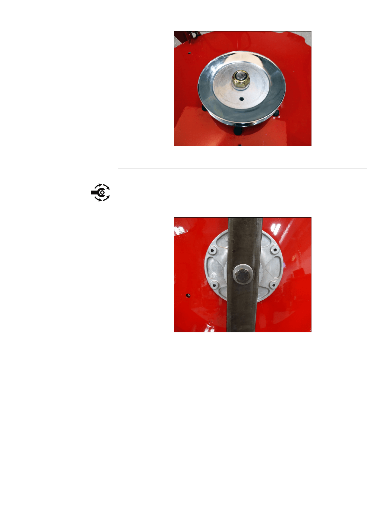
MowerSpindleInstallation(continued)
g344425
Figure90
9.Raiseandsupportthemowerdeck.
10.Fromtheundersideofthemowerdeck,installthebladescrewandwasher
securingeachmowerbladetothemowerdeck.Torquethescrewto
135.58–149N•m(100–110ft-lb).
g344424
Figure91
11.Lowerthemowerdecktothegroundtoaccessthetopsideofthemowerdeck.
12.Installthedeckdrivebeltontothemowerdeck.
13.InstalltheLHdrivebeltcovertothemowerdeck,securewith4(0.250-20x
0.500inch)screws.RepeatontheRHsideofthemachine.
14.Installthemowerdeckontothemachine.MowerDeckInstallation(page6–8)
BeltTensionerReplacement
BeltTensionerRemoval
1.Removethemowerdeck.MowerDeckRemoval(page6–5)
2.Removethe4(0.250-20x0.500inch)screwssecuringtheLHbeltcoverto
themowerdeck.RepeatontheRHsideofthemowerdeck.
TITAN®MaxServiceManual
Page6–17
MowerDeck:ServiceandRepairs
3442-428RevA
BeltTensionerRemoval(continued)
3.Removethedeckdrivebeltfromthemowerdeck.
4.Removethe(3/8-16inch)nutsecuringtheidlerpulleytotheidlerarm.
g344577
Figure92
5.Removetheidlerbeltguide,washer,idlerpulley,idlerbushing,andscrew
(0.375-16x2.5inch)fromtheidlerarm.
Note:Takenoteofthepositionofthebeltguidenexttotheidlerarm.
g344579
Figure93
1.FlangeNut5.IdlerBushing
2.BeltGuide
6.IdlerArm
3.Washer
7.Screw
4.FlatIdlerPulley
6.Removethe(5/16-18inch)angenutand(3/8-16x1.750inch)screw
securingtheendoftheidlerarmtothemowerdeck.
MowerDeck:ServiceandRepairs
Page6–18
TITAN®MaxServiceManual
3442-428RevA
BeltTensionerRemoval(continued)
g344578
Figure94
7.Removethe2washers,6frictionwashers,andspacerfromthemowerdeck.
g344580
Figure95
1.Screw4.LiftLeverBushing
2.Washer5.IdlerArm
3.FrictionWasher6.Washer
8.Removetheidlerarmfromthemowerdeck.
9.Inspectthe6frictionwashersfordamage.Replaceifnecessary.
BeltTensionerInstallation
1.Installthe(0.375-16x2.5inch)screwintotheundersideoftheidlerarm.
Verifythescrewisonthecorrectsideoftheidlerarm.
2.Installtheidlerbushing,idlerpulley,washer,idlerbeltguide,andnutonto
theidlerarm.
TITAN®MaxServiceManual
Page6–19
MowerDeck:ServiceandRepairs
3442-428RevA
BeltTensionerInstallation(continued)
g344579
Figure96
1.FlangeNut5.IdlerBushing
2.BeltGuide
6.IdlerArm
3.Washer
7.Screw
4.FlatIdlerPulley
3.Placethewasherand3frictionwashersovertheholewheretheendof
theidlerarmwillbeinstalled
4.Installtheidlerarmontowasherstack.
5.Installthespacer,3frictionwashers,andwasherontotheendoftheidlerarm.
g344580
Figure97
1.Screw4.LiftLeverBushing
2.Washer5.IdlerArm
3.FrictionWasher6.Washer
MowerDeck:ServiceandRepairs
Page6–20
TITAN®MaxServiceManual
3442-428RevA
BeltTensionerInstallation(continued)
6.Installthe(3/8-16x1.750inch)screwand(5/16-18inch)nutsecuringthe
endoftheidlerarmtothemowerdeck.Torquethescrewto40.67±4.067N
•m(30±3ft-lb).
g344578
Figure98
7.Verifytheidlerarmisinstalledinthecorrectorientation.
8.Installthedeckdrivebeltontothemowerdeck.
9.InstalltheLHbeltcoverontothemowerdeck,securewith4(0.250-20x
0.500inch)screws.RepeatontheRHsideofthe
10.Installthemowerdeckontothemachine.MowerDeckInstallation(page6–8)
TITAN®MaxServiceManual
Page6–21
MowerDeck:ServiceandRepairs
3442-428RevA


Chapter7
HydrostaticDriveSystem
TableofContents
GeneralInformation..............................................................................................................................7–2
ServiceandRepairs.............................................................................................................................7–3
HydrostaticDriveTransmissionReplacement....................................................................................7–5
HydrostaticDriveBeltReplacement...................................................................................................7–8
TITAN®MaxServiceManual
Page7–1
HydrostaticDriveSystem
3442-428RevA

GeneralInformation
TheTitanMaxseriesofmowersuseHydro-GearhydrostatictransaxleZT-3100.
Thedriveusesanengineoilwithaminimumratingof9.0cst(55SUS)at110ºC
(230ºF)andanAPIclassicationofSLisrecommended.A20W50engineoilhas
beenselectedforusebythefactoryandisrecommendedfornormaloperating
procedures.TheZT-3100oilcapacityis4.45L(150-oz)(withltersremoved).
HydrostaticDriveSystem:GeneralInformation
Page7–2
TITAN®MaxServiceManual
3442-428RevA
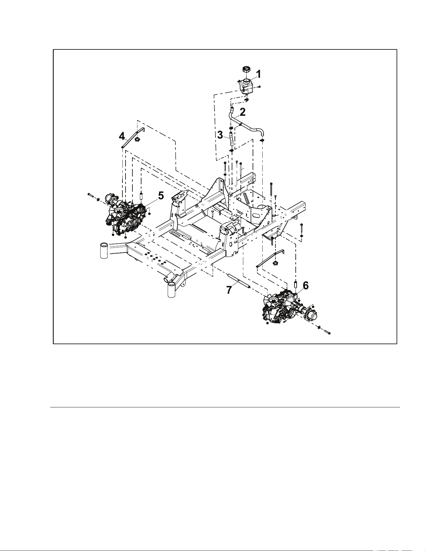
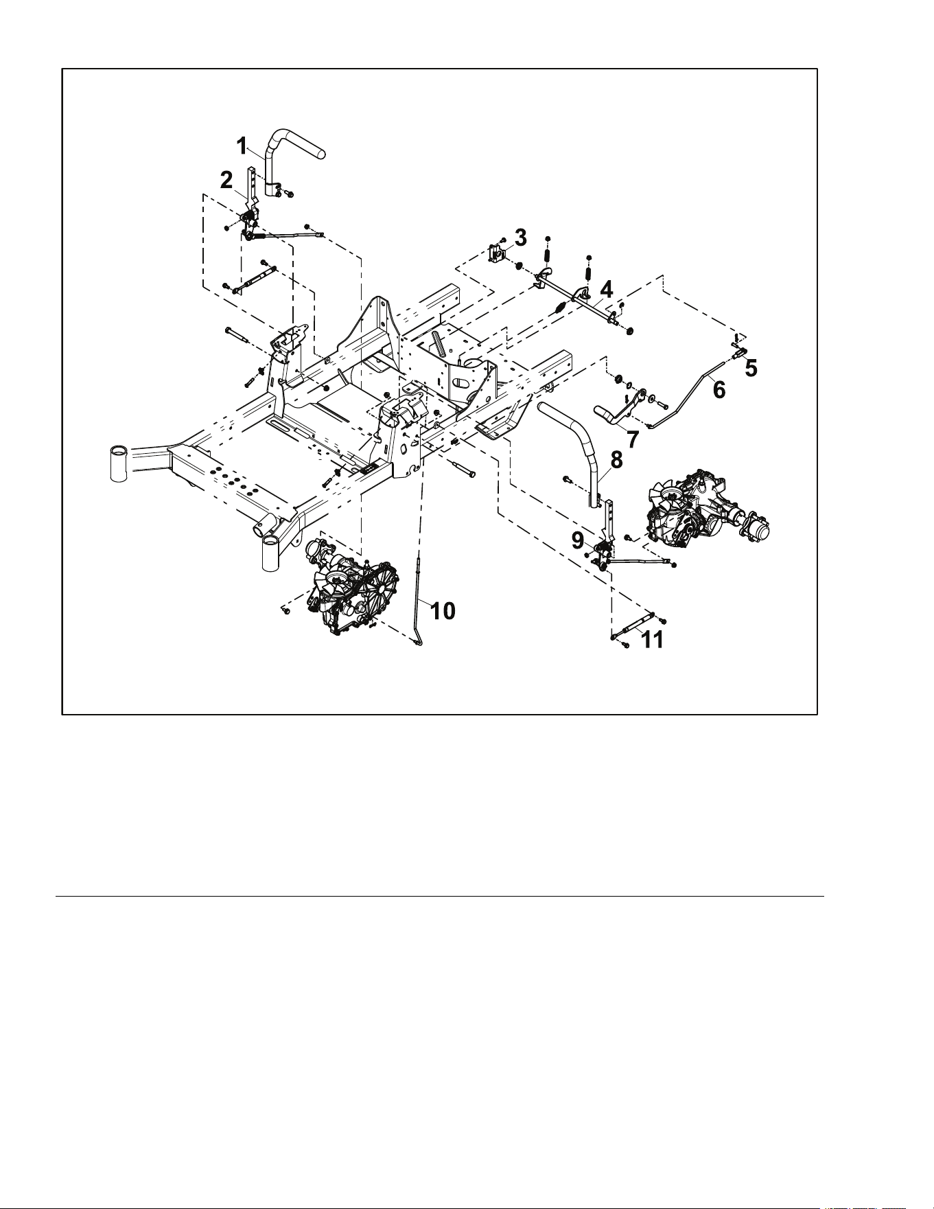
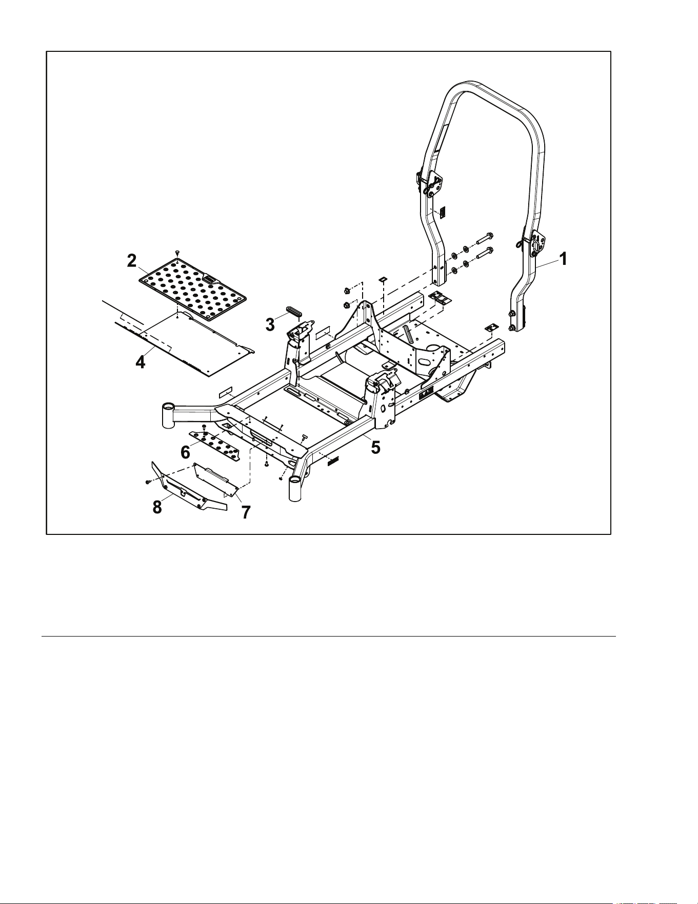
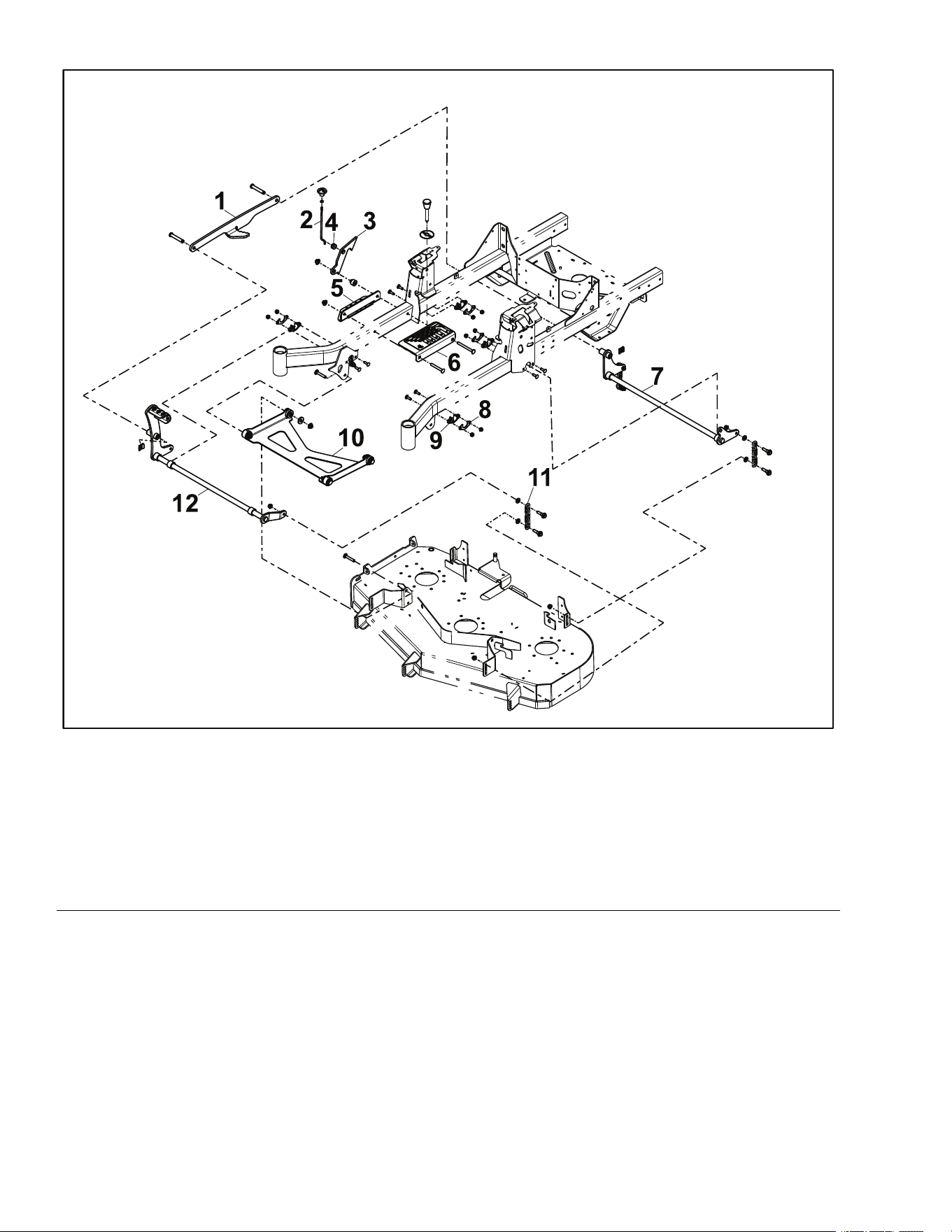
HydrostaticDriveAssembly2
g341893
Figure100
1.RHControlHandleAssembly
7.BrakeLever
2.RHMotionControlAssembly8.LHControlHandleAssembly
3.BrakeBracket
9.LHMotionControlAssembly
4.BrakeShaft
10.LowerBrakeLinkage
5.AdjustableYoke11.Damper
6.UpperBrakeLinkage
HydrostaticDriveSystem:ServiceandRepairs
Page7–4
TITAN®MaxServiceManual
3442-428RevA
HydrostaticDriveTransmissionReplacement
HydrostaticDriveTransmissionRemoval
1.ParkthemachineonalevelsurfaceanddisengagethePTO.Stoptheengine,
waitforallmovingpartstostop,andremovekey.Engagetheparkingbrake.
2.Disconnectthebatterybyremovingthenegativecablerst,thenthepositive
cablefromthebattery.
3.Raiseandsupporttheunitsothatthefrontwheelsareofftheground,block
rearwheels.
4.Removethedrivewheels.
5.Removethedeckdrivebeltfromthemowerdeck.DeckDriveBeltRemoval
(page6–10)
6.Removethehydrostaticdrivebeltfromthemachine.HydrostaticDriveBelt
Removal(page7–8)
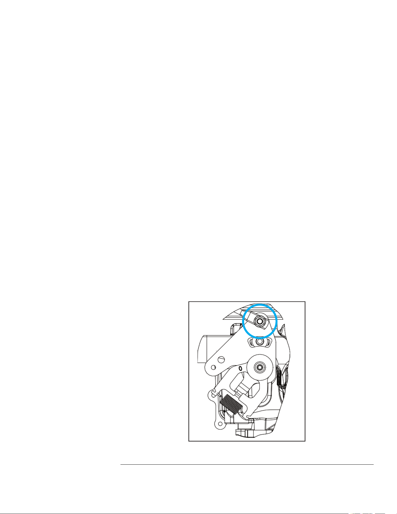
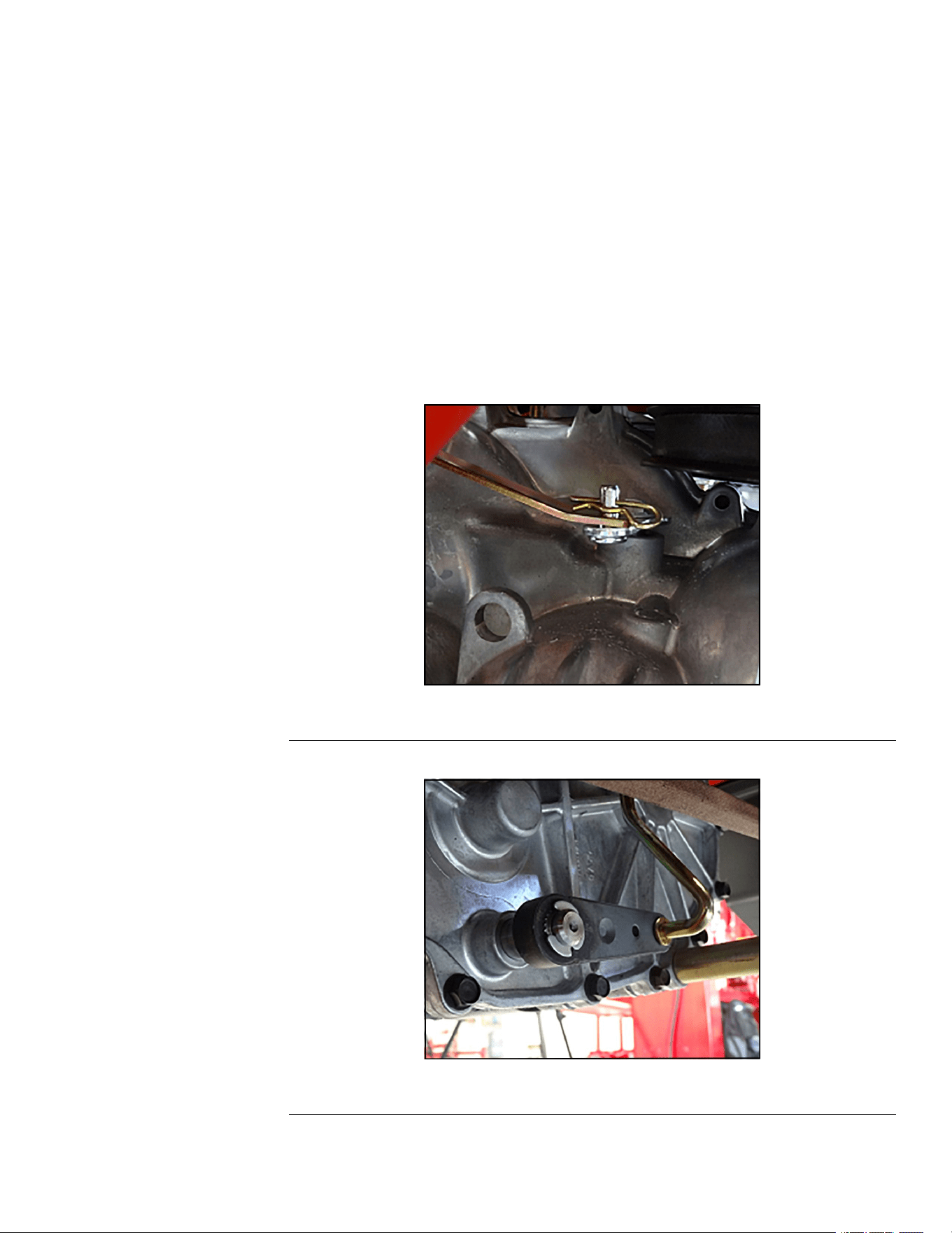
7.Disconnectthemotioncontrollinkagefromthetransmission.
8.Disconnectthebypassarm.
g336196
Figure101
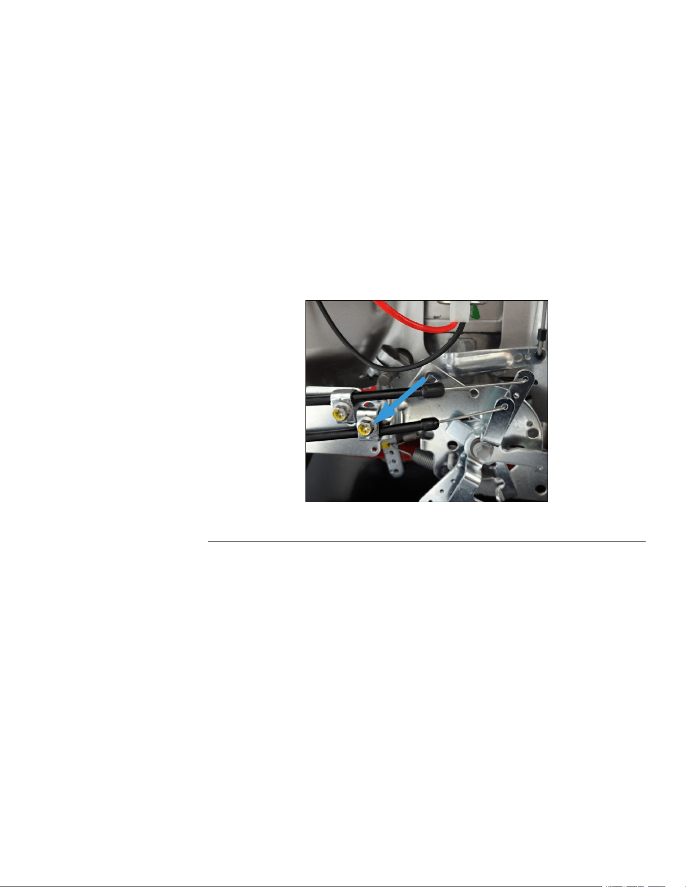
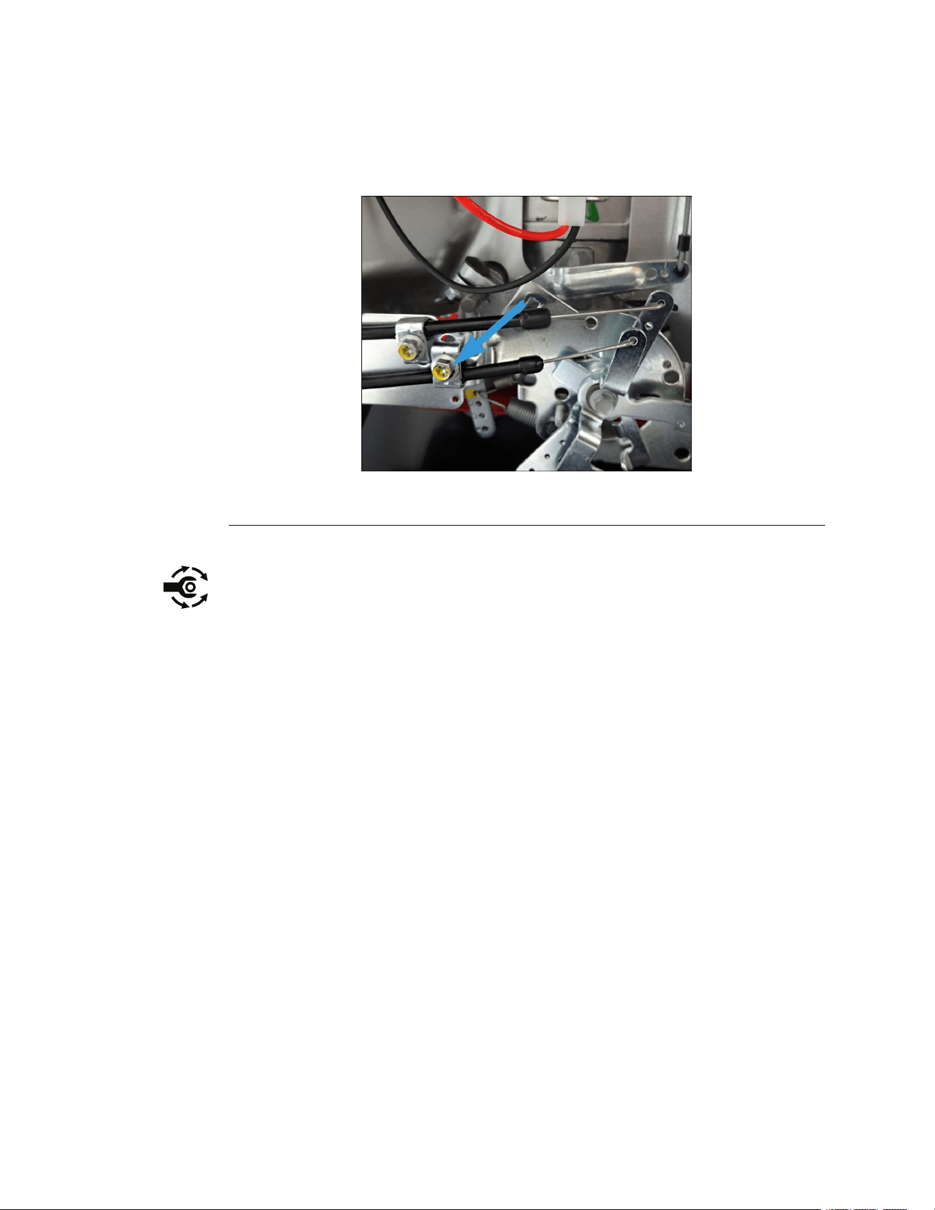
9.Disconnectthelowerbrakelinkagefromthetransmission.
g336197
Figure102
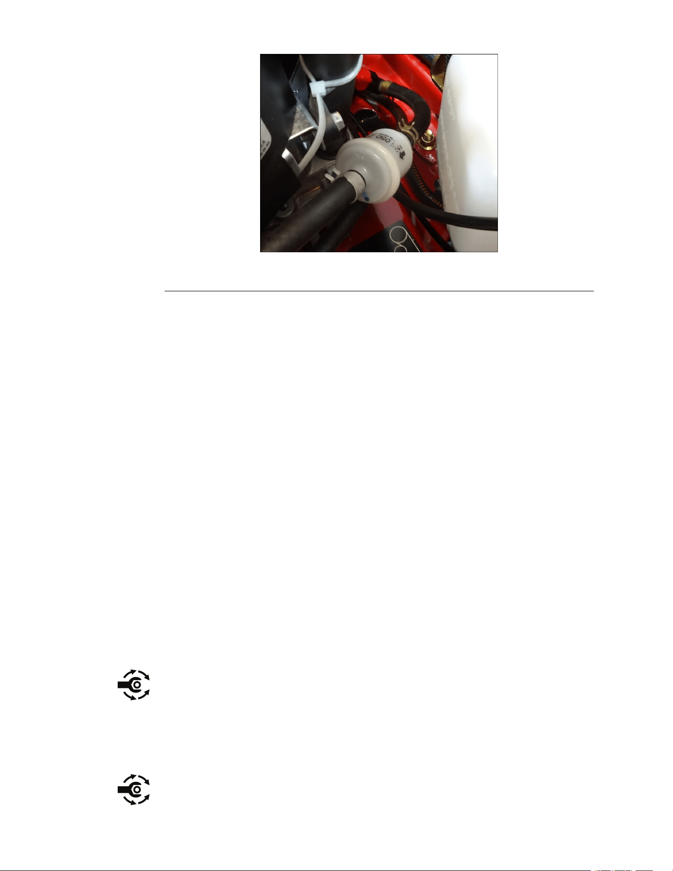
10.Disconnectthehydraulicuidhosefromthetopofthetransmission.
TITAN®MaxServiceManual
Page7–5
HydrostaticDriveSystem:ServiceandRepairs
3442-428RevA
HydrostaticDriveTransmissionRemoval(continued)
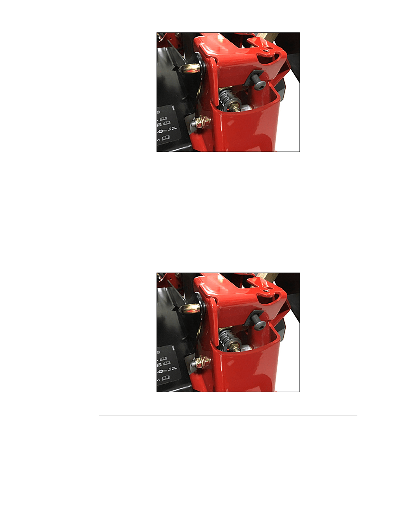
11.Removethe(0.375-16x2.00inch)screwthatconnectsthetransmissionto
thecrossshaft.
12.Removethe2(0.312-18x2.250inch)fronthydromountingscrewsand
2(5/16-18inch)nuts.
13.Removethe2(5/16-18x4.75inch)rearhydromountingscrewsand2
(5/16-18inch)nuts.
g336195
Figure103
1.FrontandRearMountingScrews3.AxleHornScrews
2.CrossShaft
14.Supportthetransmission,loosenandremovethe2(5/16-18inch)axlehorn
nuts,washers,and2(5/16-18x3.00inch)screws.Lowerthetransmission.
HydrostaticDriveTransmissionInstallation
1.Liftandsupportthetransmission,andinstallthe2(5/16-18x3.00inch)axle
hornscrews,washers,andnuts(5/16-18inch).Donotfullytightenthenuts
atthistime.
2.Alignthecrossshaftandinstallthescrew(0.375-16x2.00inch)throughthe
transmissionintothecrossshaft.Donottightenatthistime.
g336198
Figure104
HydrostaticDriveSystem:ServiceandRepairs
Page7–6
TITAN®MaxServiceManual
3442-428RevA
HydrostaticDriveTransmissionInstallation(continued)
3.Installthe2(0.312-18x2.250inch)frontand2(5/16-18x4.75inch)rear
hydromountingscrews,washers,and(5/16-18inch)nuts.Donottighten
atthistime.
4.Torquethecrossshaftscrewto61±6.779N•m(43±5ft-lb).
5.Tightentherearhydromountingscrew.
6.Tightenthe2axlehornscrew.
7.Tightenthefronthydromountingscrew.
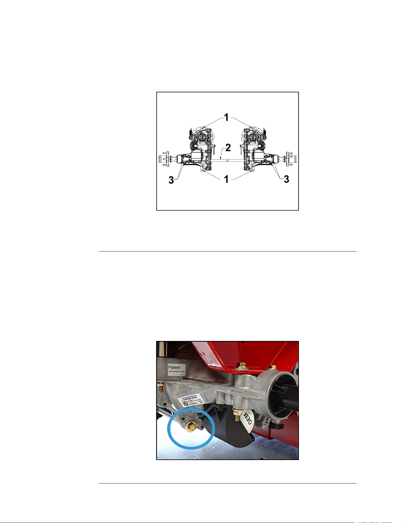
8.Removetheprotectivecapfromthehydraulicoilnipple(ifinstallinganew
hydrostaticdrive).Installthehydraulicuidhose,andmovethehoseclamp
intoplace.
9.Connectthelowerbrakelinkagetothetransmission.
10.Connectthebypassarm.
11.Connectthemotioncontrollinkage.
Note:Attachthemotioncontrollinkageasshownwiththeoffsettoward
theoutsideofthemachine.
g336199
Figure105
12.Installthehydrostaticdrivebeltontothemachine.HydrostaticDriveBelt
Installation(page7–8)
13.Installthedeckdrivebeltontothemowerdeck.DeckDriveBeltInstallation
(page6–12)
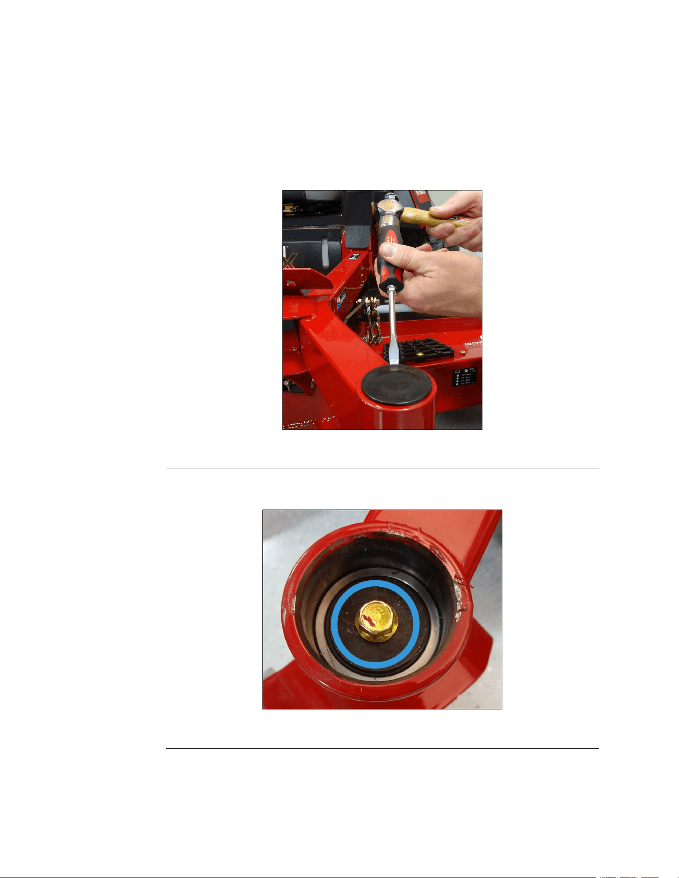
14.Verifythatthe(3/4-16inch)hubnutistorquedto325.4-352.5N•m(240–260
lb-ft).
15.Installthedrivewheelandtorquethelugnuts.T orquethenutsto122–135.58
N•m(90–100ft-lb).
16.AddhydraulicoiltothereservoirtotheFULLCOLDline.
17.Connectthebatterybyinstallingthepositivecablerst,thenthenegative
cabletothebattery.
TITAN®MaxServiceManual
Page7–7
HydrostaticDriveSystem:ServiceandRepairs
3442-428RevA

HydrostaticDriveTransmissionInstallation(continued)
18.Purgetheairoutofthesystem.RefertotheproductOperator’sManual
thepurgingairprocedures.
19.Adjusttheneutralsettingifnecessary.RefertotheproductOperator’s
Manualforadjustingtheneutralsettingprocedures.
20.Lowertheunitandverifyproperfunction.
21.Adjustthetrackingifnecessary.RefertotheproductOperator’sManual
forthetrackadjustingprocedures.
HydrostaticDriveBeltReplacement
HydrostaticDriveBeltRemoval
1.ParkthemachineonalevelsurfaceanddisengagethePTO.Stoptheengine,
waitforallmovingpartstostop,andremovekey.Engagetheparkingbrake.
2.Disconnectthebatterybyremovingthenegativecablerst,thenthepositive
cablefromthebattery.
3.Removethedeckdrivebeltfromthemowerdeck.DeckDriveBeltRemoval
(page6–10)
4.Raiseandsupporttheunitsothatthefrontwheelsareofftheground,block
rearwheels.
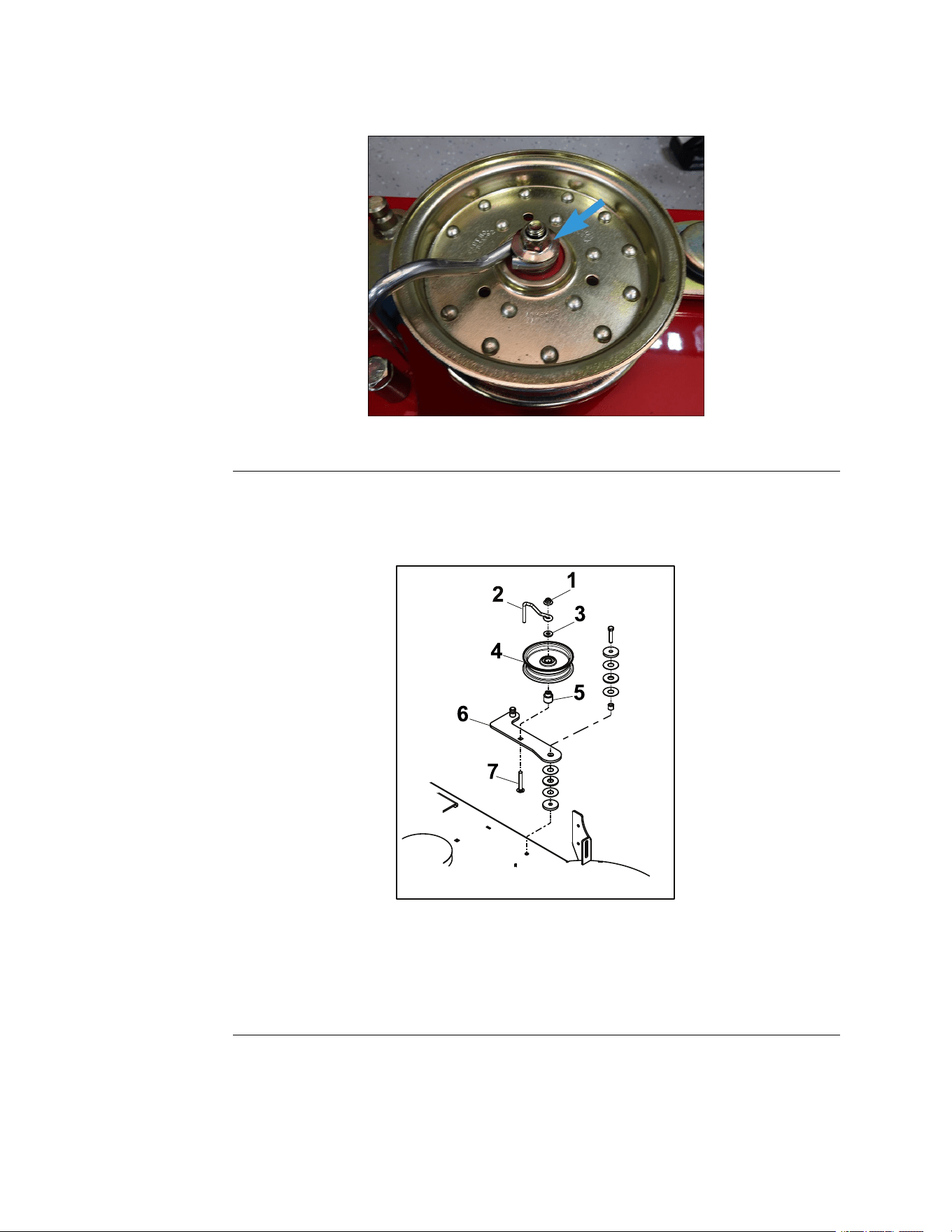
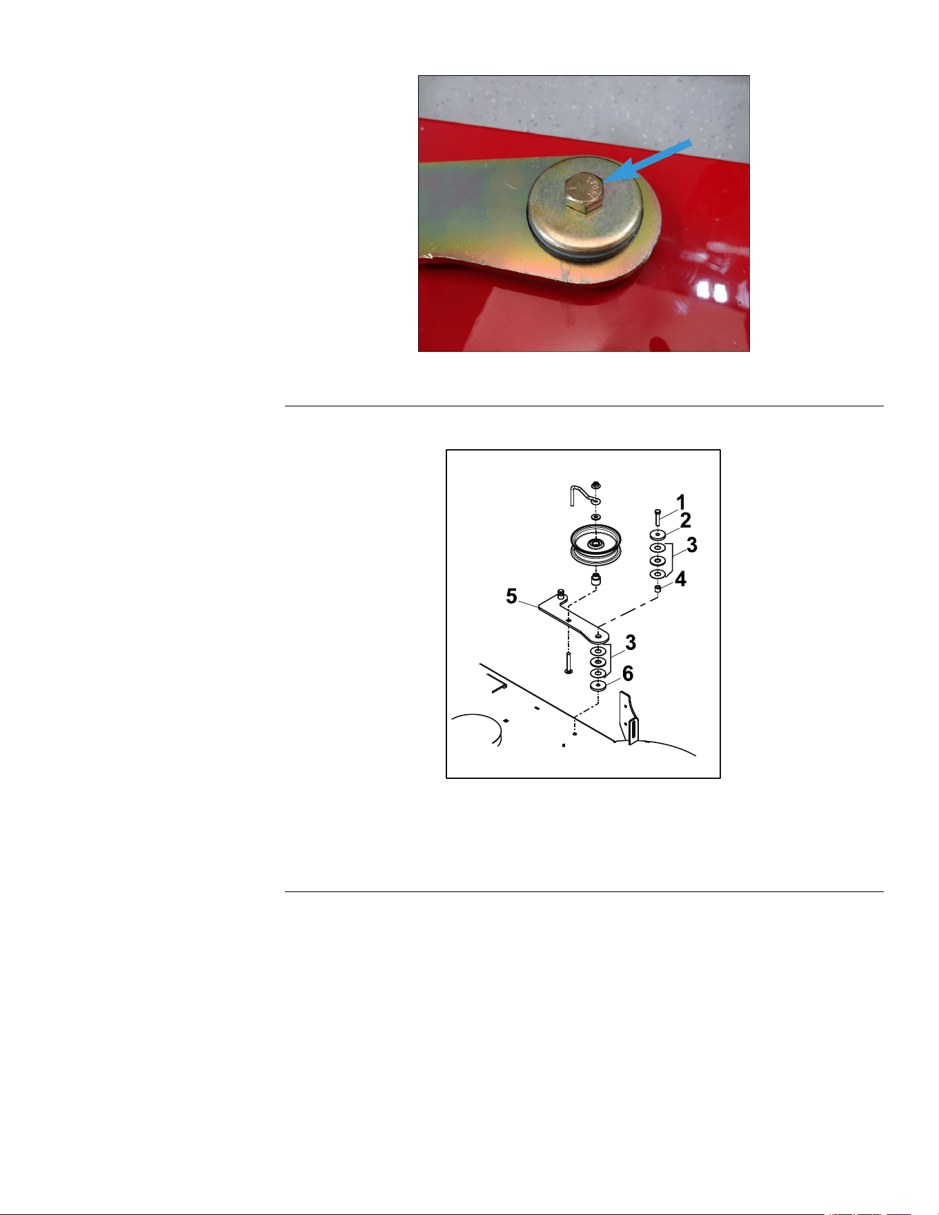
5.Removethe(0.375–16x1.500inch)screwandbellevillewashersecuring
theanchorclutch.Removetheanchorclutch.
6.Removetheidlerspringfromthepost.
7.Removethehydrostaticdrivebeltfromthepulleys.
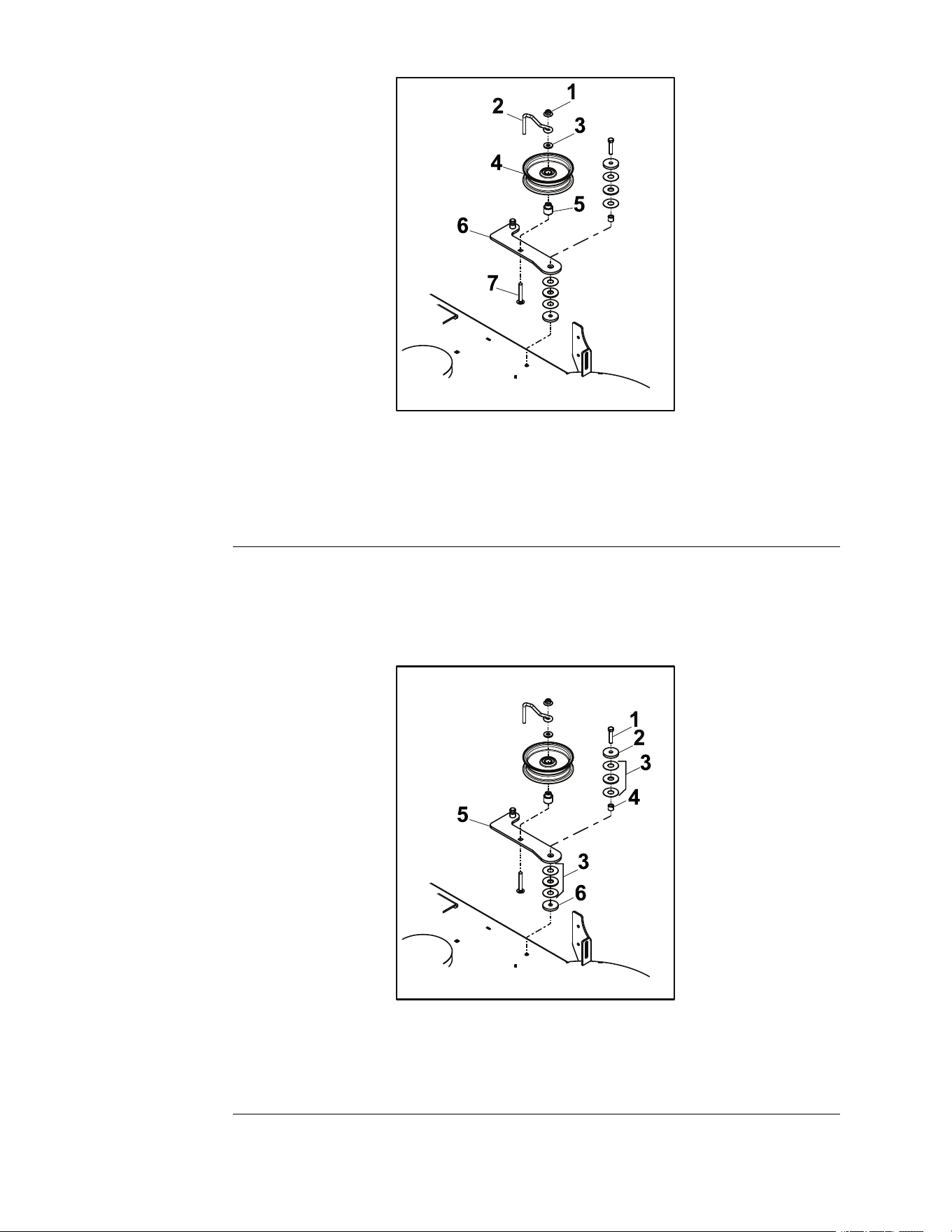
HydrostaticDriveBeltInstallation
1.Routethehydrostaticdrivebeltaroundthepulleys.
2.Installtheidlerspringontothepost.
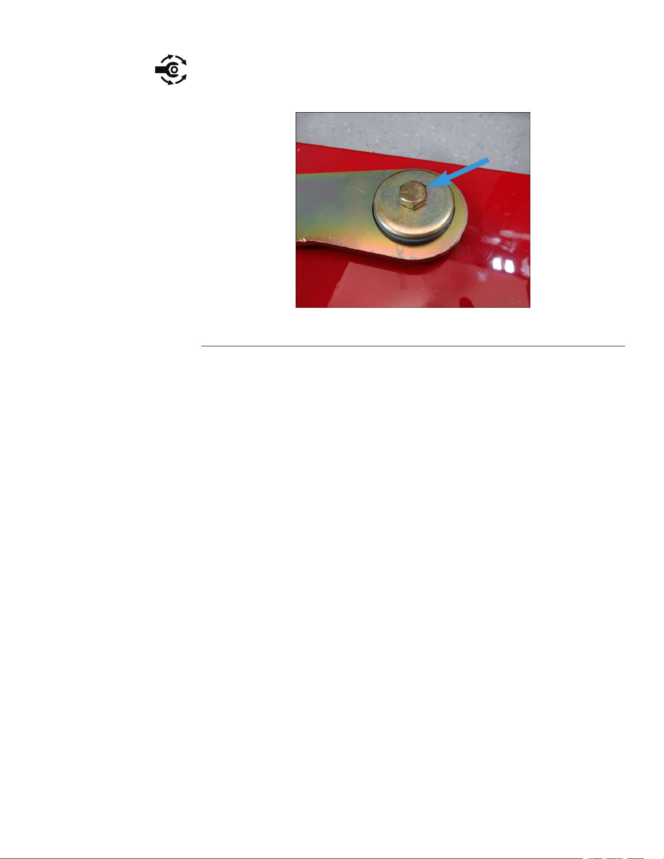
3.Installtheanchorclutchontothemachineandsecurewiththebelleville
washerand(0.375–16x1.500inch)screw.T orquethescrewto36.6–44.74
N•m(27–33ft-lb).
4.Installthedeckdrivebeltontothemowerdeck.DeckDriveBeltInstallation
(page6–12)
5.Lowertheunit.
6.Connectthebatterybyinstallingthepositivecablerst,thenthenegative
cabletothebattery.
7.Verifytheproperfunctionoftheunit.
HydrostaticDriveSystem:ServiceandRepairs
Page7–8
TITAN®MaxServiceManual
3442-428RevA

Chapter8
ElectricalSystem
TableofContents
GeneralInformation..............................................................................................................................8–2
ServiceandRepairs.............................................................................................................................8–3
FuseBlockandFuses.......................................................................................................................8–4
Key/IgnitionSwitch............................................................................................................................8–4
HourMeter.........................................................................................................................................8–5
OperatorPresenceSwitch(SeatSwitch)..........................................................................................8–6
NeutralSwitch-LeftandRight..........................................................................................................8–7
ParkingBrakeSwitch........................................................................................................................8–7
StarterSolenoid................................................................................................................................8–8
PTOSwitch........................................................................................................................................8–8
ElectricPTOClutch..........................................................................................................................8–10
TVSDiode........................................................................................................................................8–16
TITAN®MaxServiceManual
Page8–1
ElectricalSystem
3442-428RevA

GeneralInformation
TheTitanMaxutilizesa12VDCelectricalsystem.Thesystemsconsistofa
300cca12vbattery.Thesystemuse2neutrallockswitchesonthemotion
controllevers,seatswitch,brakeswitch,bladeengagementswitch(PTO),
ignitionswitch,15AMPmainfuse,and20AMPchargingsystemfuse.This
systemalsousesastartrelay,electricPTOclutch,hourmeter,TVSdiode,and
startersolenoid.
ElectricalSystem:GeneralInformation
Page8–2
TITAN®MaxServiceManual
3442-428RevA
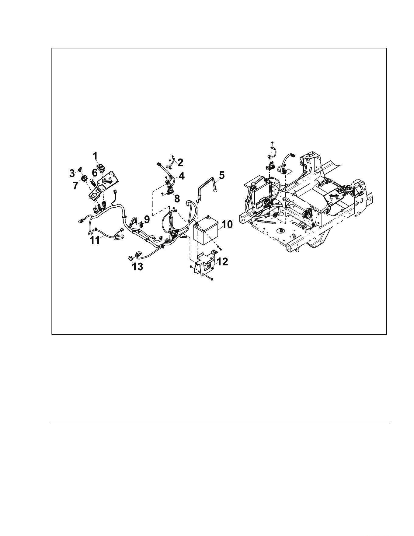
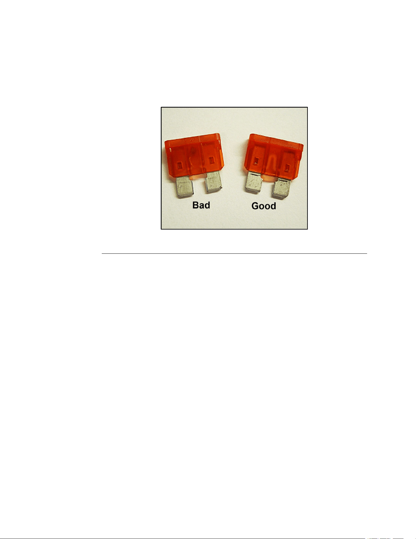
FuseBlockandFuses
Thefuseblockhousesthefusesthatprotecttheelectricalsystemfromelectrical
surges.
Note:AlwaysuseTorofuseswhenreplacingadamagedorblownfuse.
FuseBlockandFusesTest
1.Visuallyinspectthefuses.Afailedfusecanbeidentiedbyabrokenor
meltedelementinsidethefusecoveroradamagedspade.
g336414
Figure107
2.Usingadigitalmulti-metersettotheOHMorContinuitysetting,checkthe
continuitybetweenthefuseblades.IfthefuseisOPEN(nocontinuity),
replacethefuseandtestthecircuit.
Key/IgnitionSwitch
Theignitionswitchmakestheproperconnectionsforthestarter,safety
circuits,andaccessories.Detentsinsidetheswitchcontrolthethreeswitch
positions:OFF ,RUN,andSTART.TheSTARTpositionisspringloadedsothatit
automaticallyreturnstotheRUNpositionwhenreleased.
IgnitionSwitchWiringConnections
•B-BatteryVoltageIn
•S-StartingCircuit
•I-PTOSwitch
•A-OperatorPresenceSwitch,SafetyInterlockSwitches
•R-Regulator,ChargingCircuit
ElectricalSystem:ServiceandRepairs
Page8–4
TITAN®MaxServiceManual
3442-428RevA
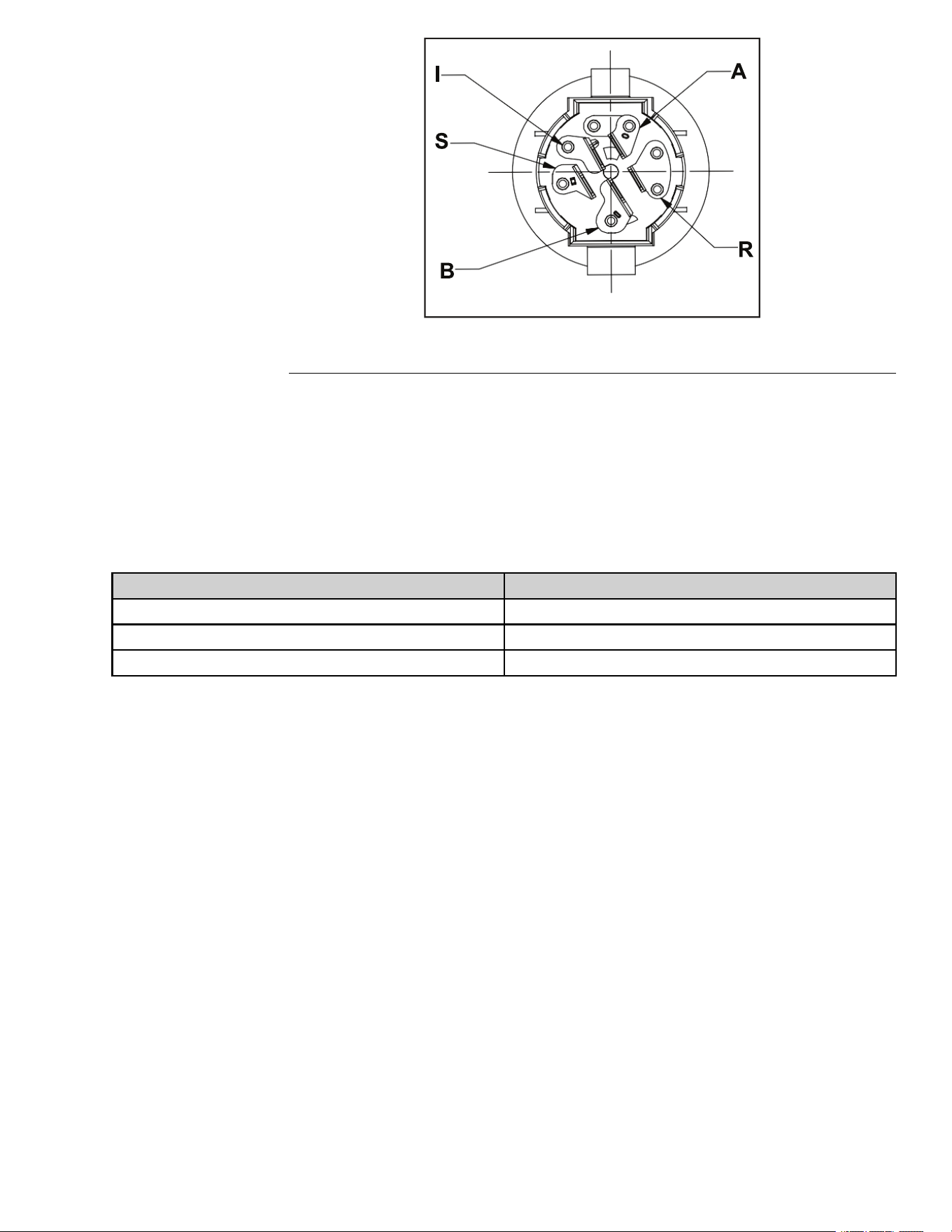
g350861
Figure108
Key/IgnitionSwitchTest
1.Removethecontrolpanelfromtherightconsole.
2.Disconnecttheignitionswitchfromthewireharness.
3.Usingadigitalmulti-metersettotheOHMorContinuitysetting,verifythat
continuityexistsbetweentheterminalslistedforeachswitchposition.
4.Usingadigitalmulti-metersettotheOHMorContinuitysetting,verifythat
NOcontinuityexistsbetweentheterminalsnotlistedforeachswitchposition.
Position
Circuit“Make”
OFF
None
RUNB+R+I+A
STARTB+R+I+S
HourMeter
ThehourmeterrecordshoursofoperationwhentheignitionkeyisONand
thePTOswitchisON.
HourMeterStatusCheck
WiththeignitionkeyintheONposition,verifythehourmeteroperationby
inspectingthehourmeterstatusicons.
•Icon2—verifythePTOstatusiconlightisilluminatedwhenthePTOswitch
isintheONposition,parkingbrakeisreleased,andtheoperatorisinthe
seat.ThePTOstatusiconlightshouldturnoffwhenthePTOswitchisturned
offortheoperatorleavestheseat.
•Icon3—verifytheparkingbrakestatusiconlightisilluminatedwhenthe
parkingbrakeisengaged.Theparkingbrakestatusiconlightshouldturn
offwhenthebrakeisdisengaged.
•Icon4—verifytheneutralstatusiconlightisilluminatedwhenbothofthe
steersticksareintheneutrallockposition.Theneutralstatusiconlight
shouldturnoffwhenthesteerssticksaremovedinwardtothedriveposition.
•Icon5—verifytheseatswitchoperationstatusiconlightisilluminedwhen
theoperatorispresentintheseat.Theseatswitchoperationstatusiconlight
shouldturnoffwhentheoperatorleavestheseat.
TITAN®MaxServiceManual
Page8–5
ElectricalSystem:ServiceandRepairs
3442-428RevA
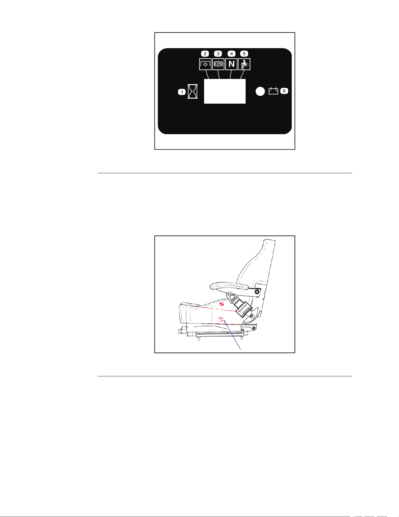
HourMeterStatusCheck(continued)
g336418
Figure109
OperatorPresenceSwitch(SeatSwitch)
WiththeignitionswitchintheRUNposition,andtheoperatorpresenceswitch
closed(operatorisintheseat),batteryvoltageissuppliedtotheneutralswitches.
Note:Theoperatorpresenceswitchispartoftheseatassembly.
g336419
Figure110
OperatorPresenceSwitch(SeatSwitch)Test
1.Disconnectthewireharnessfromtheoperatorpresenceswitch,located
onthebottomoftheseatassembly.
2.Usingadigitalmulti-metersettotheOHMorcontinuitysetting,testthe
continuitybetweenthetwoswitchterminals.
•Whentheseatisvacated,theswitchshouldNOThavecontinuity(open).
•Whentheoperatorispresent,theswitchshouldhavecontinuity(closed).
ElectricalSystem:ServiceandRepairs
Page8–6
TITAN®MaxServiceManual
3442-428RevA
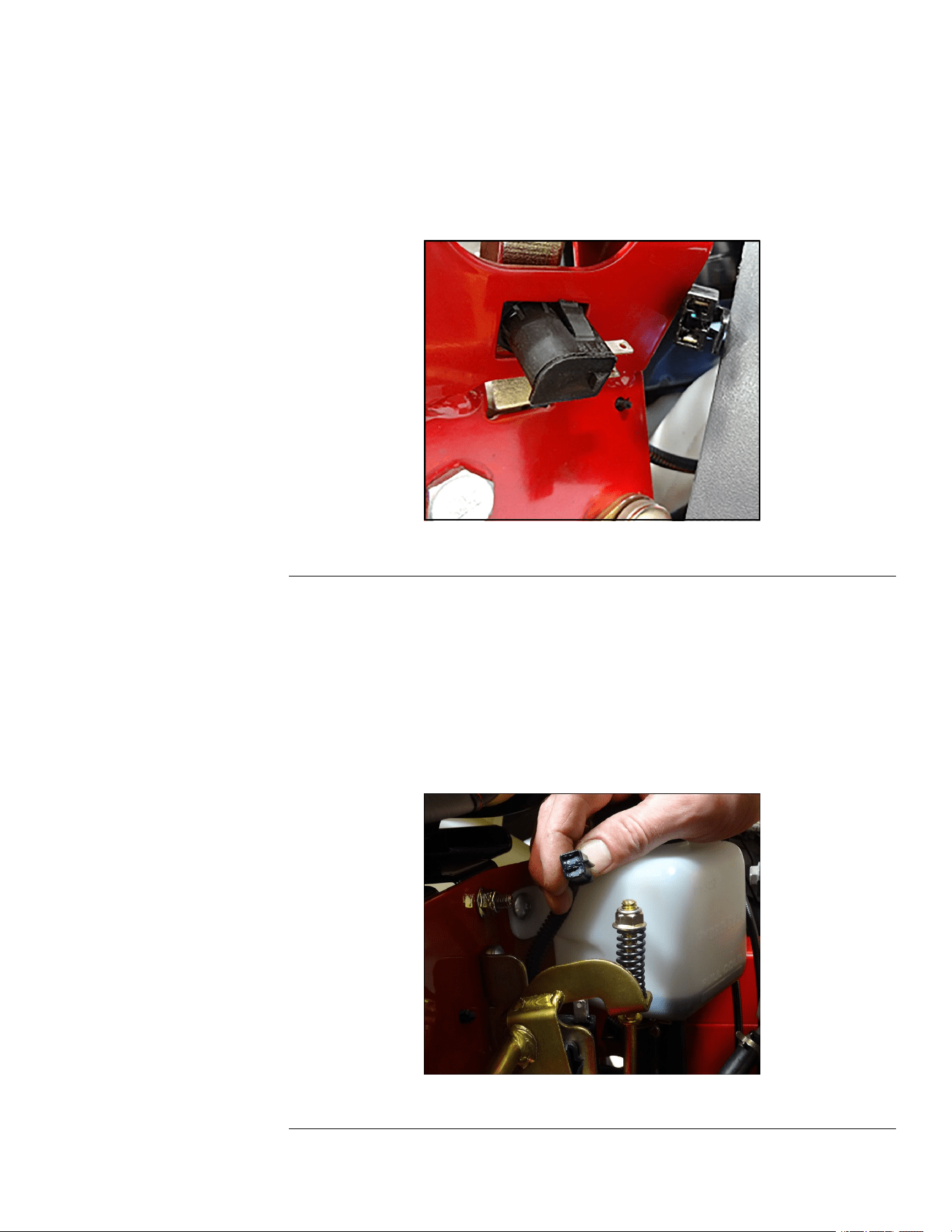
NeutralSwitch-LeftandRight
Theneutralswitchisasinglepoleplungertypeswitch(normallyopen)with
twoterminals.Whentheplungerisdepressed,thecircuitclosesandthereis
continuitybetweentheterminals.
Motioncontrolleversinneutralposition(OUT),theswitchwillhavecontinuity
(closed).
Motioncontrolleversintheoperatingposition(IN),theswitchwillNOThave
continuity(open).
g336403
Figure111
ParkingBrakeSwitch
Theparkingbrakeswitchisasinglepoleplungertypeswitch(normallyopen)
withtwoterminals.Whentheplungerisdepressed(parkingbrakeON),the
circuitclosesandthereiscontinuitybetweentheterminals.Thisallowsbattery
voltagetoowtotherestofthesafetyinterlocksystem.
ParkingbrakeON,theswitchshouldhavecontinuity(closed).
ParkingbrakeOFF,theswitchshouldNOThavecontinuity(open).
g344832
Figure112
TITAN®MaxServiceManual
Page8–7
ElectricalSystem:ServiceandRepairs
3442-428RevA
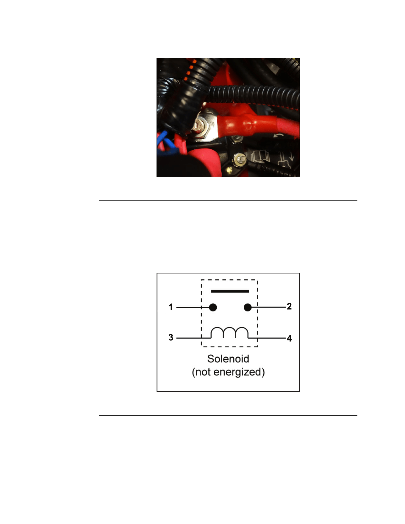
StarterSolenoid
Thesolenoidisaremoteswitchthatconnectsthebatterytothestartermotor
whentheignitionswitchisturnedtoSTART .Thesolenoidprotectstheignition
switchfromthehighcurrentdrawnbythestartermotor.
g344833
Figure113
StarterSolenoidTest
1.Disconnectthesolenoidfromthewiringharness.
2.Withamulti-metersettotheOHMorcontinuitysetting,checktoensurethat
terminals1and2areopen(nocontinuity).
3.Apply12volts(DC)toterminal3andgroundterminal4.Terminals1and2
shouldnowbeclosed(continuity).
g336407
Figure114
PTOSwitch
ThePTOswitchprovidesbatteryvoltagefromtheignitionswitchtothePTO
clutch.
Aspartofthesafetyinterlocksystem,thePTOswitchwillpreventtheengine
fromcranking/startingwhenintheONpositionbypreventingthestartrelay
fromgroundingthroughthehourmeter.
ElectricalSystem:ServiceandRepairs
Page8–8
TITAN®MaxServiceManual
3442-428RevA
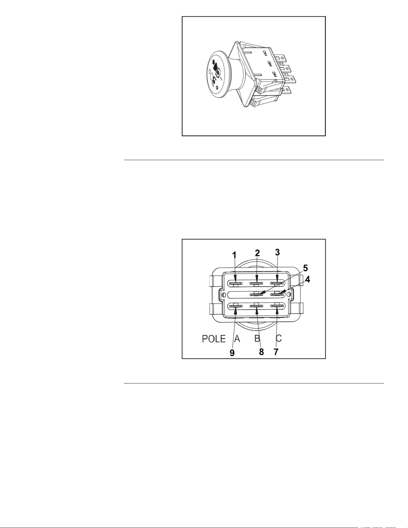
g336408
Figure115
Note:TheenginewillnotcrankoverwhenthePTOswitchisintheONposition.
AllswitchesaresuppliedinparallelandfeedintotheHourMeter.
PTOSwitchTest
1.Removethecontrolpanelfromtherightconsole.
2.DisconnectthePTOswitchfromthewireharness.
3.WiththeswitchintheONposition(buttonpulledOUT).
g336409
Figure116
4.Usingadigitalmulti-metersettotheOHMorContinuitysetting,verifythe
following:
•Pin2and5shouldhavecontinuity(closed)
•Pin1and4shouldhavecontinuity(closed)
•Pin1and7shouldNOThavecontinuity(open)
•Pin2and8shouldNOThavecontinuity(open)
5.WiththeswitchintheOFFposition(buttonpushedIN):
•Pin1and7shouldhavecontinuity(closed)
•Pin2and8shouldhavecontinuity(closed)
•Pin1and4shouldNOThavecontinuity(open)
TITAN®MaxServiceManual
Page8–9
ElectricalSystem:ServiceandRepairs
3442-428RevA
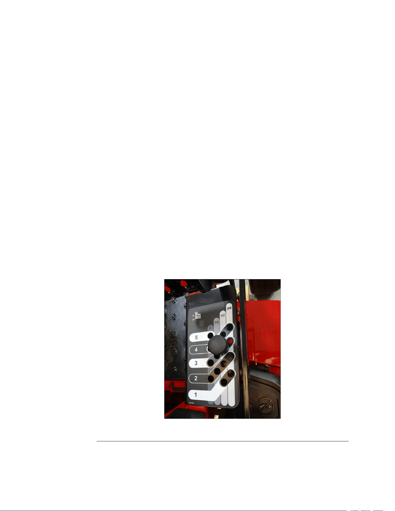
PTOSwitchTest(continued)
•Pin2and5shouldNOThavecontinuity(open)
ElectricPTOClutch
ThePTOclutchelectronicallycontrolstheengagementanddisengagement
ofthePTOpulley(deckbelt).
ThePTOclutchiscomposedofthreemajorcomponents:
•Field
•ClutchPlate
•FrictionPlate
Theclutchplatealwaysturnswiththeengine(crankshaft).Theeldisacoilof
wireonanironcorewhichbecomesanelectromagnetwhenpowerisapplied.
Thefrictionplateistheonlypiecethatmovesverticallyonthecrankshaft.Itis
normallyspringloadedsothatitisnotincontactwiththeclutchplateandis
pressedagainstthebrakematerialoppositetheclutchplate.Whenpoweris
applied,thefrictionplateispulledtowardtheclutchplateandthetworotateas
one.Whentheclutchplateandthefrictionplaterotateasdifferentspeedsit
isknownasclutchslipping.
ElectricPTOClutchRemoval
1.ParkthemachineonalevelsurfaceanddisengagethePTO.Stoptheengine,
waitforallmovingpartstostop,andremovekey.Engagetheparkingbrake.
2.Disconnectthebatterybyremovingthenegativecablerst,thenthepositive
cablefromthebattery.
3.Placetheheightofcutpinintothethirdholetolockthemowerdeckinthe
lowestheightofcutposition.
g344397
Figure117
4.Liftandremovetheoorpanfromthemachine.
ElectricalSystem:ServiceandRepairs
Page8–10
TITAN®MaxServiceManual
3442-428RevA
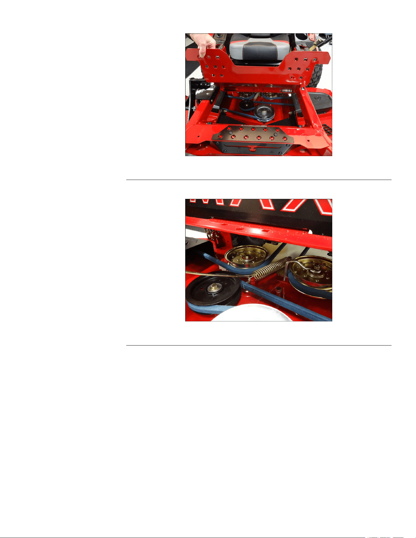
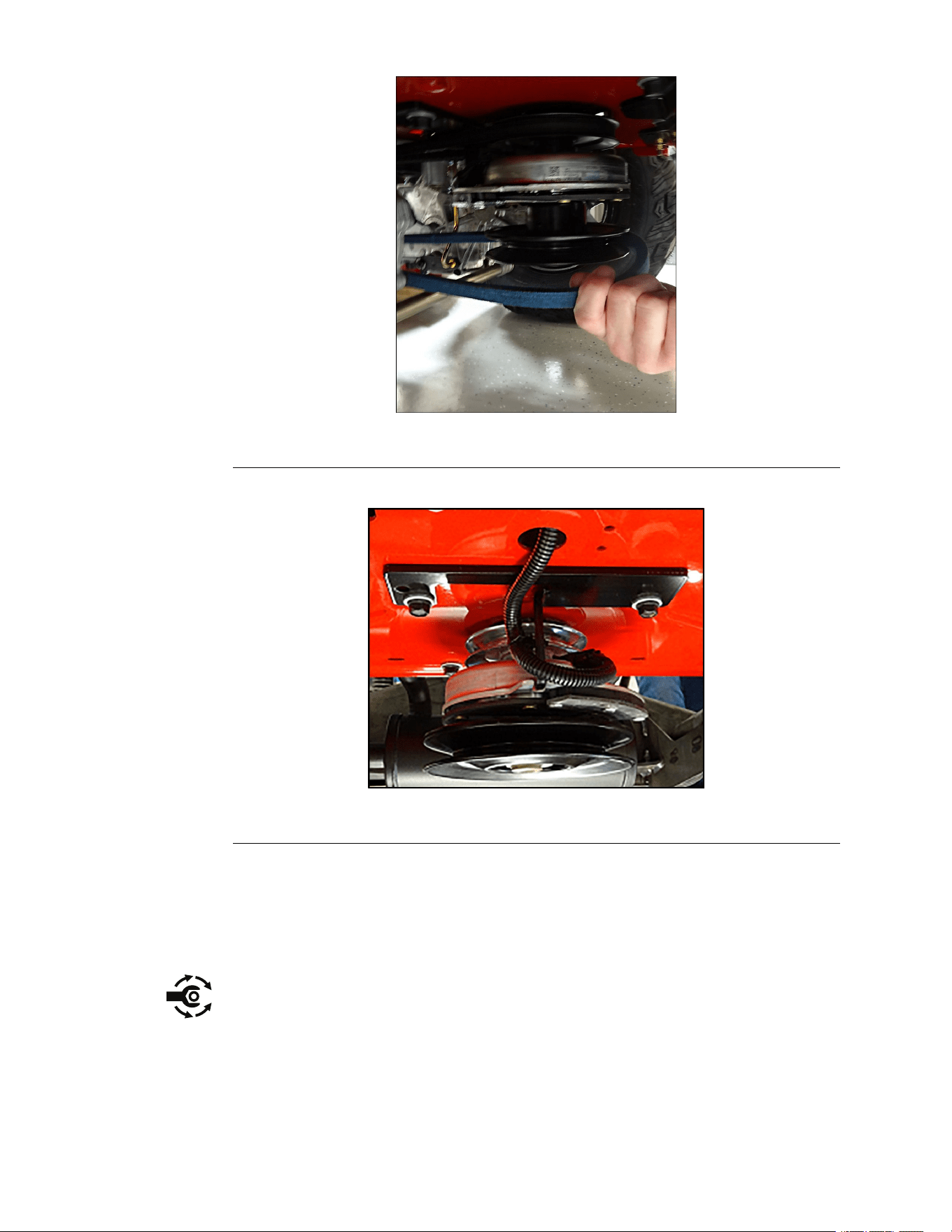
ElectricPTOClutchRemoval(continued)
g344400
Figure120
7.DisconnecttheclutchwireconnectorfromthePTOclutch.
g336161
Figure121
8.Removethescrewand2springwasherssecuringthePTOclutchtothe
machine.
9.RemovethePTOclutchfromthemachine.
ElectricPTOClutchInstallation
1.InstallthePTOclutchontotheundersideofthemachine,securewiththe2
springwashersand(7/16x3inch)screw.Torquethescrewto66.4–82.7
N•m(49–61ft-lbs).
2.ConnecttheclutchwireconnectortothePTOclutch.
ElectricalSystem:ServiceandRepairs
Page8–12
TITAN®MaxServiceManual
3442-428RevA
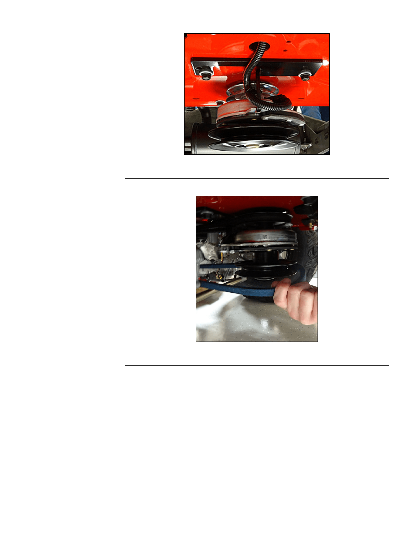
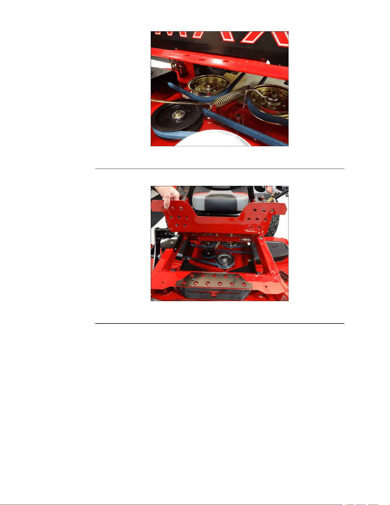
ElectricPTOClutchInstallation(continued)
g344399
Figure124
5.Installtheoorpanontothemachine.
g344398
Figure125
6.Connectthebatterybyinstallingthepositivecablerst,thenthenegative
cabletothebattery.
7.Verifytheproperfunctionofthemachine.
ElectricPTOClutch-CoilResistanceMeasurementTest
IfthePTOclutchisnotengagingorissuspectasacauseofelectricalproblems,
usethefollowingelectricaltroubleshootingsteps.Theseprocedureswillhelp
determineiftheclutchhasfailedasaresultoforisthecauseofanelectrical
problem.
1.ParkthemachineonalevelsurfaceanddisengagethePTO.Stopthe
engine,waitforallmovingpartstostopandremovethekey.Engagethe
parkingbrake.
2.Disconnecttheclutchwireconnector.
3.Setthemulti-metertomeasureresistance(OHMssetting).
4.Connectthemeterleadwirestotheterminalsintheclutchconnector.
ElectricalSystem:ServiceandRepairs
Page8–14
TITAN®MaxServiceManual
3442-428RevA
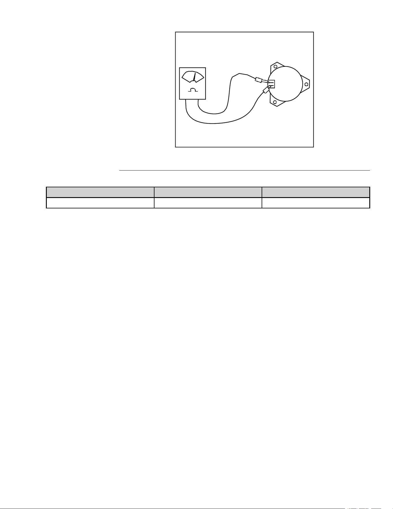
ElectricPTOClutch-CoilResistanceMeasurementTest(continued)
g336410
Figure126
5.SeethePTOClutchElectricalSpecicationschart.
Resistance(OHMs)
AMPDraw
ContinuitytoGround
3.05±5%
3.93
OPEN
ElectricPTOClutch-PTOClutchContinuitytoGroundTest
1.ParkthemachineonalevelsurfaceanddisengagethePTO.Stopthe
engine,waitforallmovingpartstostopandremovethekey.Engagethe
parkingbrake.
2.Disconnecttheclutchwireconnector.
3.Setthemulti-metertomeasureresistance(OHMsetting).
4.Connectonemulti-meterleadtotheengine,chassisorbatteryground.
Connecttheothermulti-meterleadtoeachoftheclutchconnectorterminals.
5.Theclutchconnectorterminalsshouldneverhavecontinuitytogroundand
shouldbeOPENatalltimes.
6.IfcontinuityisfoundbetweenthePTOconnectorandground,thePTOclutch
andthePTOswitchmustbereplaced.
ElectricPTOClutch-MeasuringClutchCurrentDraw
Note:Donotmeasurecurrentdrawiftheclutchhasshortedtogroundorifthe
resistancemeasurementisoutofspecication.
TITAN®MaxServiceManual
Page8–15
ElectricalSystem:ServiceandRepairs
3442-428RevA
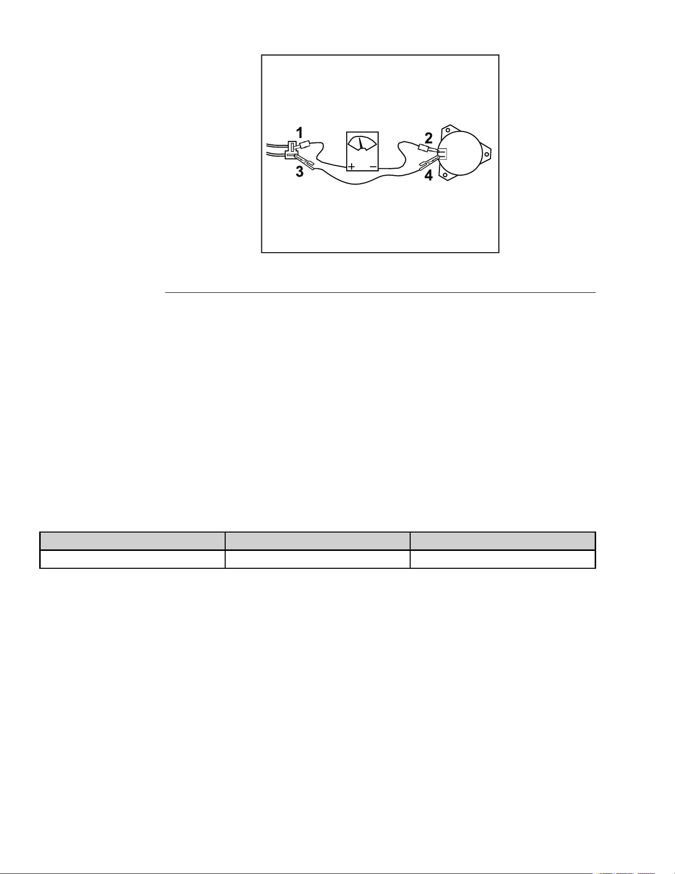
ElectricPTOClutch-MeasuringClutchCurrentDraw(continued)
g336411
Figure127
1.ParkthemachineonalevelsurfaceanddisengagethePTO.Stopthe
engine,waitforallmovingpartstostop,andremovethekey.Engagethe
parkingbrake.
2.Disconnecttheclutchwireconnector.
3.Setthemulti-metertomeasureamps(10ampscale).
4.Connectthepositivemeterleadtothechassisharnessterminal1.
5.Connectthenegativemeterleadtothecorrespondingwireterminal2.
6.Connectashortjumperleadfromterminal3toterminal4.
7.TurntheignitionswitchtoRUNandthePTOswitchtotheONposition.
8.RecordtheampreadingandrefertothePTOClutchElectricalSpecication
Chartbelow.
PTOClutchElectricalSpecicationChart
Resistance(OHMs)
AMPDraw
ContinuitytoGround
3.05±5%
3.93
OPEN
TVSDiode
TheTVSdiodeprotectstheelectricalsystemfromcurrentsurgescausedby
PTOengagementanddisengagement.
ElectricalSystem:ServiceandRepairs
Page8–16
TITAN®MaxServiceManual
3442-428RevA
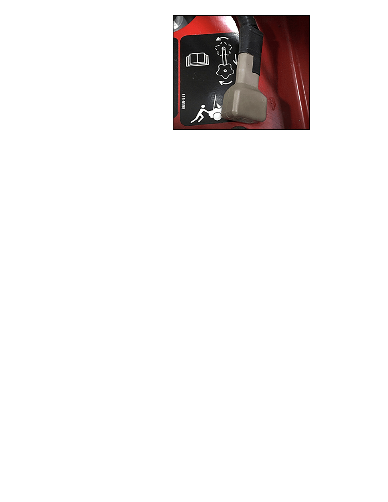
g336413
Figure128
TVSDiodeTesting
IfthemainfuseblowseachtimethePTOclutchisengaged,checktheTVS
diode.
1.DisconnecttheTVSdiodefromtheharness.
2.ConnecteachleadofthemetertoeachterminaloftheTVSdiode.
3.IftheTVSdiodeisinternallyshorted,replacetheTVSdiode.
4.IftheTVSdiodeisnotinternallyshorted,checkthewiringandtheclutch.
TITAN®MaxServiceManual
Page8–17
ElectricalSystem:ServiceandRepairs
3442-428RevA


AppendixA
FoldoutDrawings
TableofContents
ElectricalDrawingAbbreviations........................................................................................................A–2
KohlerEngineElectricalSchematic...................................................................................................A–3
TITAN®MaxServiceManual
PageA–1FoldoutDrawings
3442-428RevA

ElectricalDrawingAbbreviations
Thefollowingabbreviationsareusedforwireharnesscolorsontheelectrical
schematicsandwireharnessdrawingsinthischapter.
Abbreviation
Color
BKBlack
BRorBNBrown
BUBlue
GNGreen
GYGray
ORorOGOrange
PKPink
RorRDRed
TorTNT an
VIOorVT
Violet
WorWHWhite
YorYEYellow
Numerousharnesswiresincludealinewithanalternatecolor.Thesewiresare
identiedwiththewirecolorfollowedbya/or_andthenthelinecolor(e.g,R/BK
isaredwirewithablackline;OR_BKisanorangewirewithablackline).
Note:Theelectricalharnessdrawingsinthischapteridentifyboththewirecolor
andthewiregauge.Forexample,16BKonaharnessdiagramidentiesa
16gaugewirewithblackinsulation.
Note:Aspliceusedinawireharnesswillbeidentiedonthewireharness
diagrambySP .Themanufacturingnumberofthespliceisalsoidentiedonthe
wireharnessdiagram(e.g.,SP01issplicenumber1).
FoldoutDrawingsPageA–2
TITAN®MaxServiceManual
3442-428RevA
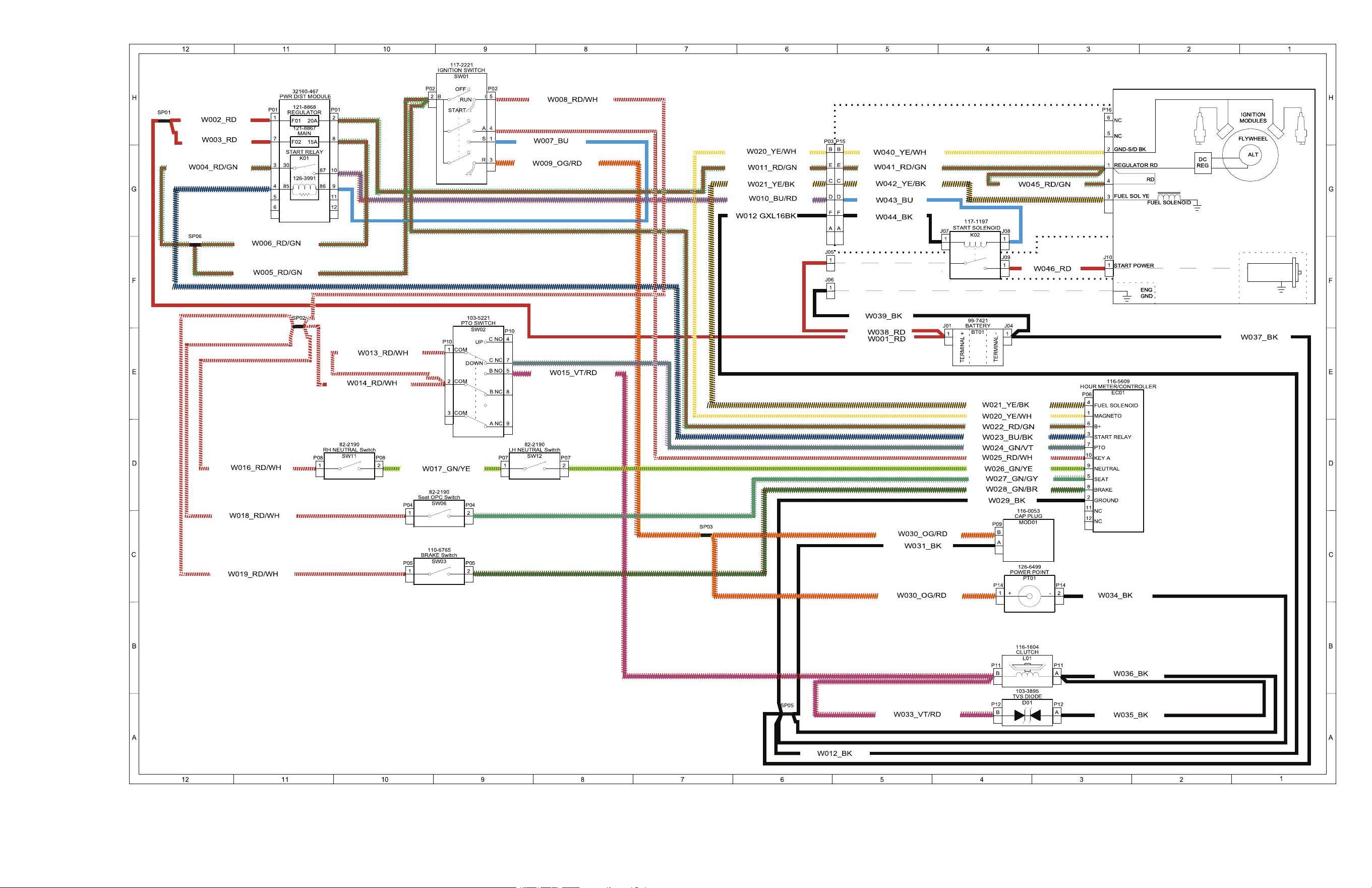
,DrawingRevA,Sheet1
3442-428RevA
PageA–3
KohlerEngineElectricalSchematic
g350654