FormNo.3438-774RevA
Published:September2020
©2020—TheToro®Company
8111LyndaleAvenueSouth
Bloomington,MN55420
OriginalInstructions(EN)
Contactusatwww.Toro.com.
AllRightsReserved
TITAN
Service
Manual
®

RevisionHistory
RevisionHistoryPage2
TitanServiceManual
3438-774RevA

Preface
ThisservicemanualwaswrittenexpresslyforToroservicetechnicians.TheT oroCompanyhasmade
everyefforttomaketheinformationinthismanualcompleteandcorrect.
Basicshopsafetyknowledgeandmechanical/electricalskillsareassumed.TheT ableofContentslists
thesystemsandtherelatedtopicscoveredinthismanual.
Wearehopefulthatyouwillndthismanualavaluableadditiontoyourserviceshop.Ifyouhaveany
questionsorcommentsregardingthismanual,pleasecontactusatthefollowingaddress:
TheToroCompany
RLC/SWSCustomerCareDepartment
8111LyndaleAvenueSouth
Bloomington,MN55420
TheToroCompanyreservestherighttochangeproductspecicationsormakechangestothismanual
withoutnotice.
TitanServiceManual
Page3
Preface
3438-774RevA

ServiceProcedureIcons
ThefollowingiconsappearthroughoutthisServiceManualtobringattentionto
specicimportantdetailsofaserviceprocedure.
CriticalProcess
Thisiconisusedtohighlight:
•Installingsafetyequipment(shields,guards,seatbelts,brakes,andR.O.P .S.
components)thatmayhavebeenremoved
•Dimensionsorsettingsthatmustbemaintainedforpropermachineoperation
•Aspecicfastenertighteningsequence
•Componentorientationthatmaynotbeobvious
CriticalTorque
Thisiconisusedtohighlightanassemblytorquerequirementthatisdifferent
thanwhatisrecommendedintheStandardTorqueT ables.
FluidSpecications
Thisiconisusedtohighlightuidspecicationsandcapacitiesthatareless
common,andmaynotappearonthemachineservicedecalorinthemachine
Operator’sManual.
Note:RefertotheservicedecalonthemachineandthemachineOperator’s
Manualforcommonlyuseduidspecicationsandcapacities.
Preface
Page4
TitanServiceManual
3438-774RevA

TableofContents
Preface................................................................................................................3
Chapter1:Safety............................................................................................1–1
SafetyInstructions.......................................................................................1–2
Chapter2:SpecicationsandMaintenance....................................................2–1
Specications...............................................................................................2–2
TorqueSpecications...................................................................................2–4
Chapter3:Troubleshooting.............................................................................3–1
GeneralTroubleshooting..............................................................................3–3
Chapter4:Engine...........................................................................................4–1
GeneralInformation.....................................................................................4–2
ServiceandRepairs.....................................................................................4–3
Chapter5:Chassis..........................................................................................5–1
GeneralInformation.....................................................................................5–2
ServiceandRepairs.....................................................................................5–3
Chapter6:HydrostaticDriveSystem...............................................................6–1
GeneralInformation.....................................................................................6–2
ServiceandRepairs.....................................................................................6–3
Chapter7:MowerDeck...................................................................................7–1
GeneralInformation.....................................................................................7–2
ServiceandRepairs.....................................................................................7–3
Chapter8:Electrical........................................................................................8–1
GeneralInformation.....................................................................................8–2
ServiceandRepairs.....................................................................................8–3
AppendixA......................................................................................................A–1
ElectricalDrawingAbbreviations...................................................................A–2
ElectricalSchematic.....................................................................................A–3
TitanServiceManual
Page5
Preface
3438-774RevA

Preface
Page6
TitanServiceManual
3438-774RevA

Chapter1
Safety
TableofContents
SafetyInstructions................................................................................................................................1–2
ThinkSafetyFirst...............................................................................................................................1–2
TitanServiceManual
Page1–1
Safety
3438-774RevA
SafetyInstructions
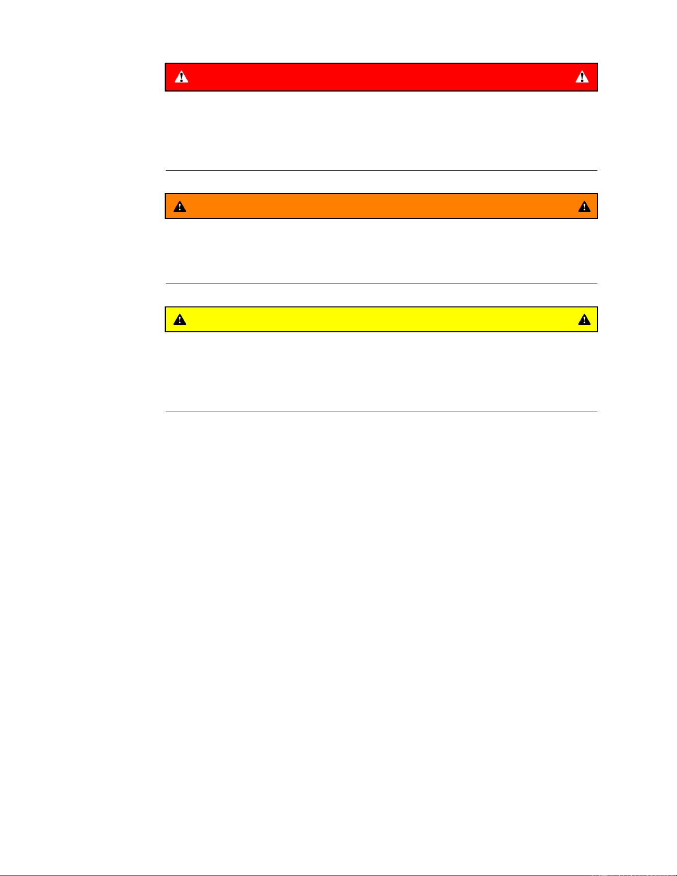
DANGER
Thissafetysymbolmeansdanger.Whenyouseethissymbol,
carefullyreadtheinstructionsthatfollow.Failuretoobeythe
instructionscouldcauseseriouspermanentinjury,disability,or
death.
WARNING
Thissafetysymbolmeanswarning.Whenyouseethissymbol,
carefullyreadtheinstructionsthatfollow.Failuretoobeythe
instructionscanresultinseriousinjury.
CAUTION
Thissafetysymbolmeanscaution.Whenyouseethissymbol,
carefullyreadtheinstructionsthatfollow.Failuretoobeythe
instructionscanresultinminortomoderateinjuryand/ordamage
topropertyorequipment.
ThinkSafetyFirst
Avoidunexpectedstartingofengine…
Alwaysturnofftheengine,removetheignitionkeyanddisconnectthesparkplug
wire(s)beforecleaning,adjusting,orrepair.
Avoidlacerationsandamputations…
Stayclearofallmovingpartswhenevertheengineisrunning.Treatallnormally
movingpartsasiftheyweremovingwhenevertheengineisrunningorhas
thepotentialtostart.
Avoidburns…
Donottouchtheengine,mufer,orothercomponents,whichmaybehotduring
operation,whiletheunitisrunningorshortlyafterithasbeenrunning.
Avoidresandexplosions…
Useextremecareinhandlingfuel.Itisammableanditsvaporsareexplosive.
Extinguishallcigarettes,cigars,pipes,andothersourcesofignition.Avoid
spillingfuelandneversmokewhileworkingwithanytypeoffuelorlubricant.
Wipeupanyspilledfueloroilimmediately.Neverremovethefuelcaporadd
fuelwhentheengineisrunning.Alwaysuseapproved,labeledcontainersfor
storingortransportingfuelandlubricants.Donotaddordrainfuelinanenclosed
space.Donotstorethemachineorfuelcontainerwherethereisanopename,
spark,orpilotlight,suchasonawaterheaterorotherappliance.
Avoidasphyxiation…
Donotoperateanengineinaconnedareawithoutproperventilation.
Avoidinjuryfrombatteries…
Safety:SafetyInstructions
Page1–2
TitanServiceManual
3438-774RevA

ThinkSafetyFirst(continued)
Batteryacidispoisonousandcancauseburns.Avoidcontactwithskin,eyes
andclothing.Batterygasescanexplode.Keepcigarettes,sparksandames
awayfromthebattery.
Avoidinjuryduetoinferiorparts…
Useonlyoriginalequipmentpartstoensurethatimportantsafetycriteriaaremet.
Avoidinjurytobystanders…
Alwayscleartheareaofbystandersbeforestartingortestingpowered
equipment.
Avoidinjuryduetoprojectiles…
Alwayscleartheareaofsticks,rocksoranyotherdebristhatcouldbepickedup
andthrownbythepoweredequipment.
Avoidmodications…
Neveralterormodifyanypartunlessitisafactoryapprovedprocedure.
Avoidunsafeoperation…
Alwaystestthesafetyinterlocksystemaftermakingadjustmentsorrepairson
themachine.RefertotheElectricalsectioninthismanualformoreinformation.
Avoidelectricalshock…
Nevertouchelectricalwiresorcomponentswhiletheengineisrunning.They
canbesourcesofshock.De-energizethesystemifyouarehavingtodorepairs.
Iftestingelectricalcomponentsensureyouareworkinginadryenvironment.
HydraulicSystem...
Releaseallpressureinthehydraulicsystembeforeperforminganyworkon
thesystem.Keepyourbodyandhandsawayfrompin-holeleaksornozzles
thatejecthydraulicuidunderhighpressure.Donotuseyourhandstosearch
forleaks.Hydraulicuidescapingunderpressurecanhavesufcientforceto
penetrateundertheskinandcauseseriousinjury.Seekmedicalattentionright
awayifhydraulicuidgetsintheskin.
PersonalProtectiveEquipment…
Tiebacklonghair,anddonotwearlooseclothingorjewelry.Useappropriate
personalprotectiveequipment(PPE)forprotectingyourselffrompotential
hazardsintheenvironmentinwhichyouwillwork.Eachprocessoutlinedinthis
manualmayneeddifferentPPEtoprotecttheserviceperson.Usetheproper
PPEforthetaskathand.
Tools…
Alltoolsshouldbeinproperworkingorder.Donotusetoolsthatarebrokenorin
disrepair.Usethepropertoolfortheproperapplication.
Lifts,Hoists,andJacks…
Alllifts,hoists,andjacksshouldbeusedinaccordancewiththemanufacturer
information.Inspectlifts,hoists,andjackspriortouse.Donotoverloadlifts,
hoists,andjacks.Donotworkunderasuspendedload.Ensurechockblocks
areusedonequipmentthatcanmove.Useliftsorjacksandjackstandsthat
areratedtosupportthetotalweightofthemachineandanyattachments.Do
notrelyonjackstosupportthemachine.Ifyouareunsureoftheoperationof
anylifts,hoists,andjacksdonotuse.
FireExtinguishers…
TitanServiceManual
Page1–3
Safety:SafetyInstructions
3438-774RevA

ThinkSafetyFirst(continued)
Theproperclassofreextinguishershouldbeusedincaseofre.
ClassAextinguishersareforordinarycombustiblematerialssuchaspaper,
wood,cardboard,andmostplastics.Thenumericalratingonthesetypesof
extinguishersindicatestheamountofwateritholdsandtheamountofreitcan
extinguish.Geometricsymbol(greentriangle).
ClassBresinvolveammableorcombustibleliquidssuchasgasoline,
kerosene,greaseandoil.ThenumericalratingforclassBextinguishers
indicatestheapproximatenumberofsquarefeetofreitcanextinguish.
Geometricsymbol(redsquare).
ClassCresinvolveelectricalequipment,suchasappliances,wiring,circuit
breakersandoutlets.NeverusewatertoextinguishclassCres-theriskof
electricalshockisfartoogreat!ClassCextinguishersdonothaveanumerical
rating.TheCclassicationmeanstheextinguishingagentisnon-conductive.
Geometricsymbol(bluecircle).
ABCreextinguishersareadrychemicaltypeusedformultiplepurposes.See
aboveinformationfordescription.Ensurereextinguishersareserviceableand
replaceanythataredischargedoroutofinspectiondates
Safety:SafetyInstructions
Page1–4
TitanServiceManual
3438-774RevA

Chapter2
SpecicationsandMaintenance
TableofContents
Specications.......................................................................................................................................2–2
TorqueSpecications...........................................................................................................................2–4
EquivalentsandConversions.............................................................................................................2–9
U.S.toMetricConversions..............................................................................................................2–10
TitanServiceManual
Page2–1
SpecicationsandMaintenance
3438-774RevA
Specications
Model75301753027530375310
EngineMakeToroKawasaki
EngineModelToroV-Twin24.5HP708ccTwin21.5HP726cc
EngineModel
LC2P77FFR651–S12–R(CARB)
Crankcase
Capacity
1.8L(61oz);withoutlter;2.4L(81oz)withlter
50deg-100+degSAE30
32deg-100+degSAE20W–50
20deg-85degSAE10W–30
20deg-100+degSAE10W–40
-20deg-40degSAE5W–20
HighIdle3600±100rpm
LowIdle1750±150rpm
SparkPlugChampion:RN9YC
NGK:BPR6ES
EngineOil40deg-100+degSAE30
0deg-80degSAE5W–30,10W–30
-20deg-100+degsynthetic5wW–20,5W–30,10W–30
OilCapacity2.4L(81oz)withlterchange
CARB
NoYes
EPAYes
AirFilter
CanisterStandard
FuelCapacity
5gallons
DisplayHourmeter
Battery
12volt–300CCA
ClutchWarner—105ft-lb
Clutch
Adjustment
Non-adjustable
HydraulicDriveSystem
TransmissionZT-2800
Transmission
Lubricant
4.45L(150oz)ToroHYPR-OIL®500hydraulicuidorMobil120W-50oil
MaxGround
Speed(FWD)
Upto8.5mph
MaxGround
Speed(REV)
Upto5mph
RearTires22x11x10
RearTire
Pressure
13psi
Model753117531275313
EngineMakeToro
EngineModelToroV-Twin24.5HP708cc
EngineModel
LC2P77F
SpecicationsandMaintenance:Specications
Page2–2
TitanServiceManual
3438-774RevA

Model753117531275313
CrankcaseCapacity1.8L(61oz);withoutlter;2.4L(81oz)withlter
50deg-100+degSAE30
32deg-100+degSAE20W–50
20deg-85degSAE10W–30
20deg-100+degSAE10W–40
-20deg-40degSAE5W–20
HighIdle3600±100rpm
LowIdle1750±150rpm
SparkPlugChampion:RN9YC
NGK:BPR6ES
EngineOil40deg-100+degSAE30
0deg-80degSAE5W–30,10W–30
-20deg-100+degsynthetic5wW–20,5W–30,10W–30
OilCapacity2.4L(81oz)withlterchange
CARB
No
EPAYes
AirFilter
Canister
FuelCapacity
5gallons
DisplayHourmeter
Battery
12volt–300CCA
ClutchWarner—105ft-lb
ClutchAdjustment
Non-adjustable
HydraulicDriveSystem
TransmissionZT-2800
Transmission
Lubricant
4.45L(150oz)T oroHYPR-OIL®500hydraulicuidorMobil120W-50oil
MaxGroundSpeed
(FWD)
Upto8.5mph
MaxGroundSpeed
(REV)
Upto5mph
RearTires22x11x10
RearTirePressure13psi
TitanServiceManual
Page2–3
SpecicationsandMaintenance:Specications
3438-774RevA
TorqueSpecications
Therecommendedfastenertorquevaluesarelistedinthefollowingtables.For
criticalapplications,asdeterminedbyToro,eithertherecommendedtorqueora
torquethatisuniquetotheapplicationisclearlyidentiedandspeciedinthe
servicemanual.
Thesetorquespecicationsfortheinstallationandtighteningoffastenersshall
applyforallfastenerswhichdonothaveaspecicrequirementidentiedin
theservicemanual.Thefollowingfactorsshallbeconsideredwhenapplying
torque:cleanlinessofthefastener,useofathreadsealant(Loctite),degreeof
lubricationonthefastener,presenceofaprevailingtorquefeature,hardness
ofthesurfaceunderneathofthefastener’shead,orsimilarconditionwhich
affectstheinstallation.
Asnotedinthefollowingtables,torquevaluesshouldbereducedby25%for
lubricatedfastenerstoachievethesimilarstressasadryfastener.Torquevalues
mayalsohavetobereducedwhenthefasteneristhreadedintoaluminumor
brass.Thespecictorquevalueshouldbedeterminedbasedonthealuminum
orbrassmaterialstrength,fastenersize,lengthofthreadengagement,etc.
Thestandardmethodofverifyingtorqueshallbeperformedbymarkingalineon
thefastener(headornut)andmatingpart,thenbackofffastener1/4ofaturn.
Measurethetorquerequiredtotightenthefasteneruntilthelinesmatchup.
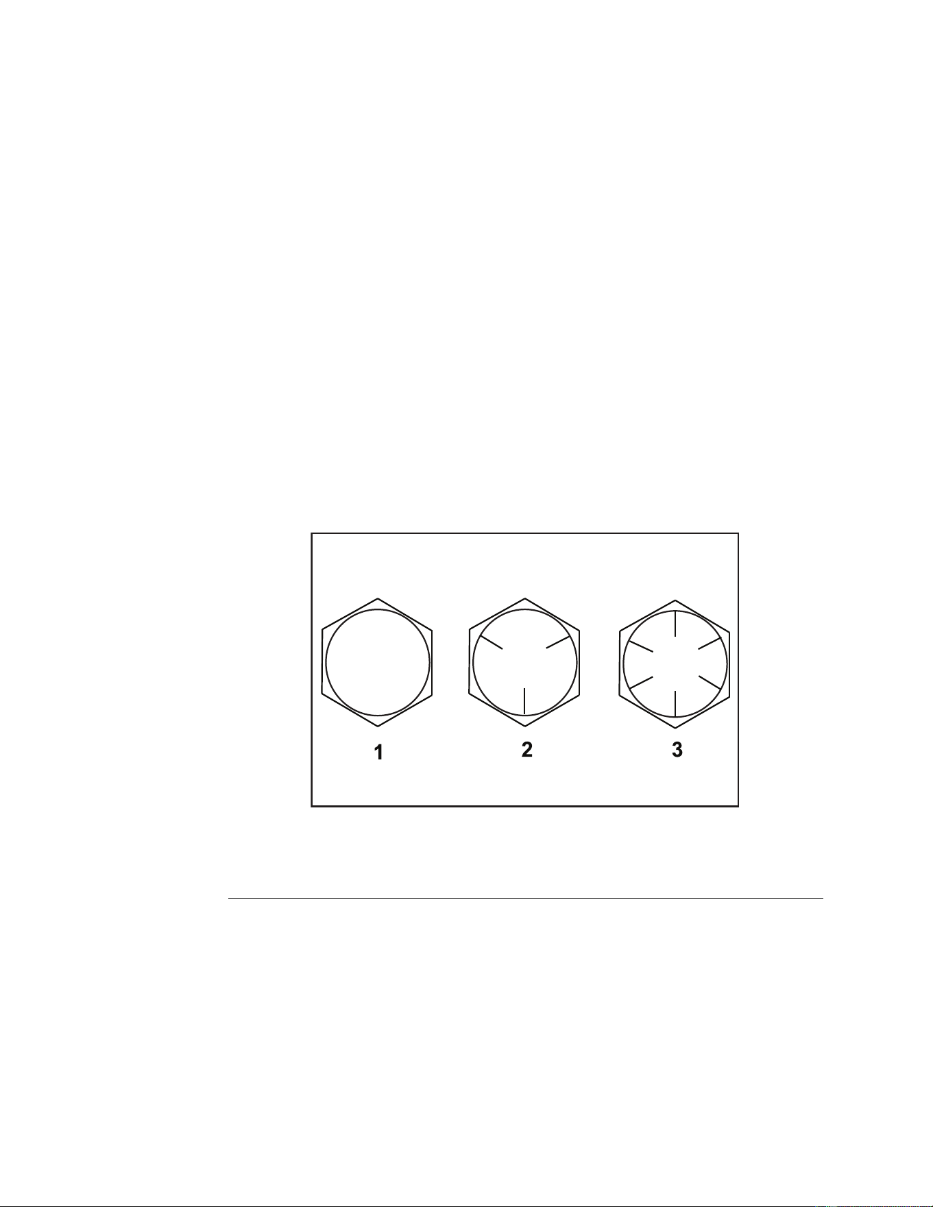
FastenerIdentication
InchSeriesBoltsandScrews
g272208
Figure1
1.Grade13.Grade8
2.Grade5
SpecicationsandMaintenance:TorqueSpecications
Page2–4
TitanServiceManual
3438-774RevA

StandardTorqueforDry,ZincPlated,andSteelFasteners(InchSeries)
ThreadSizeGrade1,
5,&8
Fasteners
withThin
HeightNuts
SAEGrade1Bolts,Screws,
Studes&Semswith
RegularHeightNuts(SAE
Grade2orBetterNut)
SAEGrade5Bolts,Screws,
Studs&SemswithRegular
HeightNuts(SAEGrade
5orBetterNut)
SAEGrade8Bolts,Screws,
Studs&SemswithRegular
HeightNuts(SAEGrade
8orBetterNut)
in-lbin-lbN•cmin-lbN•cmin-lbN•cm
#6-32UNC
15±2169±2323±3260±34
#6-40UNF
10±213±2147±23
17±2192±2325±3282±34
#8-32UNC
29±3328±3441±5463±56
#8-36UNF
13±225±5282±30
31±4350±4543±5486±56
#10-24UNC
42±5475±5660±6678±68
#10-32UNF
18±230±5339±56
48±5542±5668±7768±79
1/4-20UNC
48±753±7599±79100±101130±113140±151582±169
1/4-28UNF
53±765±10734±113115±121299±136160±171808±192
5/16-18UNC
115±15105±151186±169200±252260±282300±303390±339
5/16-24UNF
138±17128±171446±192225±252542±282325±333672±373
ft-lbft-lb
N•m
ft-lb
N•m
ft-lb
N•m
3/8-16UNC
16±216±222±330±341±443±558±7
3/8-24UNF
17±218±224±335±447±550±668±8
7/16-14UNC
27±327±337±450±568±770±795±9
7/16-20UNF
29±329±339±455±675±877±8104±11
1/2-13UNC
30±348±765±975±8102±11105±11142±15
1/2-20UNF
32±453±772±985±9115±12120±12163±16
5/8-11UNC
65±1088±12119±16150±15203±20210±21285±28
5/8-18UNF
75±1095±15129±20170±18230±24240±24325±33
3/4-10UNC
93±12140±20190±27265±27359±37375±38508±52
3/4-16UNF
115±15165±25224±34300±30407±41420±43569±58
7/8-9UNC
140±20225±25305±34430±45583±61600±60813±81
7/8-14UNF
155±25260±30353±41475±48644±65667±66904±89
Note:Reducetorquevalueslistedinthetableaboveby25%forlubricatedfasteners.Lubricated
fastenersaredenedasthreadscoatedwithalubricantsuchasoil,graphite,orthreadsealantsuch
asLoctite.
Torquevaluesmyhavetobereducedwheninstallingfastenersintothreadedaluminumorbrass.The
specictorquevalueshouldbedeterminedbasedonthefastenersize,thealuminumorbasematerial
strength,lengthofthreadengagement,etc.
ThenominaltorquevalueslistedaboveforGrade5and8fastenersarebasedon75%oftheminimum
proofloadspeciedinSAEJ429.Thetoleranceisapproximately±10%ofthenominaltorquevalue.
Thinnutsincludejamnuts.
SpecicationsandMaintenance:TorqueSpecications
Page2–6
TitanServiceManual
3438-774RevA
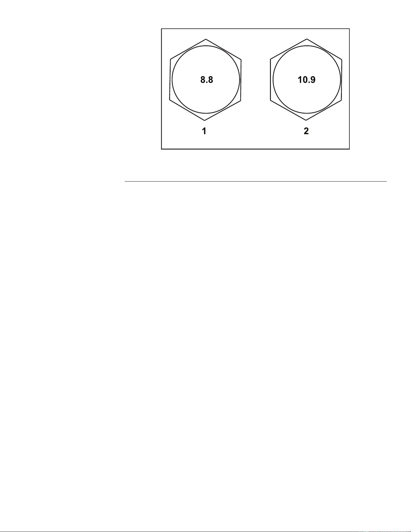
StandardTorqueforDry,ZincPlated,andSteelFasteners(MetricSeries)
Class8.8Bolts,Screws,StudswithRegular
HeightNuts(Class8orStrongerNuts)
Class10.9Bolts,Screws,StudswithRegular
HeightNuts(Class10orstrongerNuts)
ThreadSize
in-lbN•cmin-lbN•cm
M5X0.857±6644±6878±8881±90
M6X1.096±101085±113133±141503±158
ft-lb
N•m
ft-lb
N•m
M8X1.2519±226±328±338±4
M10X1.538±452±554±673±8
M12X1.7566±790±1093±10126±14
M16X2.0166±17255±23229±23310±31
M20X2.5325±33440±45450±46610±62
Note:Reducetorquevalueslistedinthetableaboveby25%forlubricatedfasteners.Lubricated
fastenersaredenedasthreadscoatedwithalubricantsuchasoil,graphite,orthreadsealantsuch
asLoctite.
Torquevaluesmayhavetobereducedwheninstallingfastenersintothreadedaluminumorbrass.The
specictorquevalueshouldbedeterminedbasedonthefastenersize,thealuminumorbasematerial
strength,lengthofthreadengagement,etc.
Thenominaltorquevalueslistedabovearebasedon75%oftheminimumproofloadspeciedinSAE
J1199.Thetoleranceisapproximately±10%ofthenominaltorquevalue.Thinheightnutsincludejam
nuts.
TitanServiceManual
Page2–7
SpecicationsandMaintenance:TorqueSpecications
3438-774RevA
SAEGrade8SteelSetScrews
RecommendedTorque
ThreadSize
SquareHeadHexSocket
1/4-20UNC
140±20in-lb73±12in-lb
5/16-18UNC
215±35in-lb145±20in-lb
1/2-13UNC75±15ft-lb50±10ft-lb
3/8-16UNC35±10ft-lb18±3ft-lb
WheelBoltsandLugNuts
ThreadSizeRecommendedTorque**
7/16-20UNFGrade565±10ft-lb
88±14N•m
1/2-20UNFGrade580±10ft-lb
108±14N•m
M12X1.25Class8.880±10ft-lb
108±14N•m
M12X1.5Class8.880±10ft-lb
108±14N•m
**Forsteelwheelsandnon-lubricatedfasteners.
ThreadCuttingScrews(ZincPlatedSteel)
Type1,Type23,orTypeF
ThreadSizeBaselineTorque*
No.6-32UNC
20±5in-lb
No.8-32UNC
30±5in-lb
No.10-24UNC
38±7in-lb
1/4-20UNC
85±15in-lb
5/16-18UNC
110±20in-lb
3/8-16UNC
200±100in-lb
*Holesize,materialstrength,materialthicknessandnishmustbeconsideredwhendetermining
specictorquevalues.Alltorquevaluesarebasedonnon-lubricatedfasteners.
ConversionFactors
in-lbX11.2985=N•cm
ft-lbX1.3558=N•m
N•cmX0.08851=in-lb
N•cmX0.73776=ft-lb
ThreadCuttingScrews(ZincPlatedSteel)
ThreadsperInch
ThreadsSize
TypeATypeB
BaselineTorque*
No.6182020±5in-lb
No.8151830±5in-lb
No.10121638±7in-lb
No.12111485±15in-lb
*Holesize,materialstrength,materialthicknessandnishmustbeconsideredwhendetermining
specictorquevalues.Alltorquevaluesarebasedonnon-lubricatedfasteners.
SpecicationsandMaintenance:TorqueSpecications
Page2–8
TitanServiceManual
3438-774RevA

EquivalentsandConversions
DecimalandMillimeterEquivalents
FractionsDecimals
mm
FractionsDecimals
mm
1/64
0.0156250.397
33/64
0.51562513.097
1/32
0.031250.794
16/32
0.5312513.484
3/64
0.0468751.191
35/64
0.54687513.891
1/16
0.06251.588
9/16
0.562514.288
5/64
0.0781251.984
37/64
0.57812514.684
3/32
0.93752.381
19/32
0.5937515.081
1/8
0.12503.175
5/8
0.625015.875
9/64
0.1406253.572
41/64
0.64062516.272
5/32
0.156253.969
21/32
0.6562516.669
11/64
0.1718754.366
43/64
0.67187517.066
3/16
0.18754.762
11/64
0.687517.462
13/64
0.2031255.159
45/64
0.70312517.859
7/32
0.218755.556
23/32
0.7187518.256
15/64
0.2343755.953
47/64
0.73437518.653
1/4
0.25006.350
3/4
0.750019.050
17/64
0.2656256.747
49/64
0.76562519.447
9/32
0.281257.144
25/32
0.7812519.844
19/64
0.2968757.541
51/64
0.79687520.241
5/16
0.31257.541
13/16
0.812520.638
21/64
0.3281258.334
53/64
0.82812521.034
11/32
0.343758.731
27/32
0.8437521.431
23/64
0.3593759.128
55/64
0.85937521.828
3/8
0.37509.525
7/8
0.875022.225
25/64
0.3906259.922
57/64
0.89062522.622
13/32
0.4062510.319
29/32
0.9062523.019
27/64
0.42187510.716
59/64
0.92187523.416
7/16
0.437511.112
15/16
0.937523.812
29/64
0.45312511.509
61/64
0.95312524.209
15/32
0.4687511.906
31/32
0.9687524.606
31/64
0.48437512.303
63/64
0.98437525.003
1/2
0.500012.70011.00025.400
1mm=0.03937in.0.001in.=0.0254mm
TitanServiceManual
Page2–9
SpecicationsandMaintenance:TorqueSpecications
3438-774RevA

U.S.toMetricConversions
ToConvert
IntoMultiplyBy
MilesKilometers1.609
YardsMeters0.9144
FeetMeters0.3048
Feet
Centimeters
30.48
InchesMeters0.0254
Inches
Centimeters
2.54
LinearMeasurement
InchesMillimeters25.4
SquareMilesSquareKilometers
2.59
SquareFeetSquareMeters
0.0929
SquareInchesSquareCentimeters
6.452
Area
AcreHectare0.4047
CubicYardsCubicMeters
0.7646
CubicFeetCubicMeters
0.02832
Volume
CubicInchesCubicCentimeters
16.39
Tons(Short)
MetricTons0.9078
PoundsKilograms0.4536 Weight
OuncesGrams
28.3495
Pressure
Pounds/SquareInch
Kilopascal6.895
Foot-PoundsNewton-Meters1.356
Foot-PoundsKilogram-Meters0.1383
Work
Inch-Pounds
Kilogram-Centimeters
1.152144
Quarts
Liters0.9463
LiquidVolume
Gallons
Liters3.785
LiquidFlows
Gallons/MinuteLiters/Minute
3.785
1.Subtractby32°
TemperatureFahrenheit
Celsius
2.Multiplyby5/9
SpecicationsandMaintenance:TorqueSpecications
Page2–10
TitanServiceManual
3438-774RevA


GEARS
TheSystematicapproachtodening,diagnosingandsolvingproblems.
GatherInformation
•Informationreportedbythecustomer
•Informationobservedbyyou
G
•Establishthewhat,whereandwhenoftheissue
EvaluatePotentialCauses
•Considerpossiblecausesoftheproblemtodevelopahypothesis
E
•Narrowdownthefocusoftheproblem
AssessPerformance
•Ensureyouhaveallthenecessarytoolsfortesting
•T estallpotentialcausesofthefailure
A
•Reevaluateandcreatenewhypothesesifnecessary
Repair
R
•Returntheunittoservicebyrepairing,rebuildingorreplacing
SolutionConrmation
•Didtheissuegoaway
•Wastherootcauseoftheissuecorrectlyrepaired
S
•Arethereanyothernewsymptoms
Troubleshooting:GeneralTroubleshooting
Page3–2
TitanServiceManual
3438-774RevA

GeneralTroubleshooting
Problem
PossibleCauseCorrectiveAction
Thebladecontrolswitch(PTO)is
engaged.
Movethebladecontrolswitch(PTO)to
thedisengagedposition.
Theparkingbrakeisnotengaged.
Settheparkingbrake.
Themotioncontrolleversarenotinthe
neutrallockposition.
Ensurethatthemotioncontrollevers
areintheneutrallockposition.
Theoperatorisnotseated.
Sitontheseat.
Thebatteryisdead.
Chargethebattery.
Theelectricalconnectionsarecorroded
orloose.
Checktheelectricalconnectsforgood
contact.
Thefuseisblown.Replacethefuse.
Thestarterdoesnotcrank
Therelayorswitchiswornordamaged.
Testandreplacefaultyrelayorswitch.
Thefueltankisempty.Fillthefueltank.
Thefuelshut-offvalveisclosed.Openthefuelshut-offvalve.
Theoillevelinthecrankcaseislow.Addoiltothecrankcase.
Thethrottleisnotinthecorrectposition.Ensurethatthethrottleismidway
betweentheslowandfastpositions.
Thereisdirtinthefuellter.Replacethefuellter.
Thereisdirt,water,orstalefuelinthe
fuelsystem.
Cleanandushthefuelsystem.
Theaircleanerisdirty.
Cleanorreplacetheaircleaner
element.
Theseatswitchisnotfunctioning
properly.
Checktheseatswitchfunction.
Replacetheseatifnecessary.
Theelectricalconnectionsare
corroded,loose,ordamaged.
Checktheelectricalconnectionsfor
goodcontact.Cleantheconnector
terminalsthoroughlywithelectrical
contactcleaner.Applydielectric
grease,andmaketheappropriate
connections.
Therelayorswitchiswornordamaged.
Testandreplacefaultyrelayorswitch.
Thesparkplugisfouledorimproperly
gapped.
Adjustorreplacethesparkplug.
Theenginedoesnotstart,starts
hard,orfailstokeeprunning
Thesparkplugwireisnotconnected.
Checkthesparkplugwireconnection.
Theengineloadisexcessive.Reducethegroundspeed.
Theaircleanerisdirty.
Cleantheaircleanerelement.
Theoillevelinthecrankcaseislow.Addoiltothecrankcase.
Thecoolingnsandairpassages
abovetheengineareplugged.
Removetheobstructionandthoroughly
cleancoolingnsandtheairpassages.
Theventholeinthefuelcapisplugged.Cleanorreplacethefuelcap.
Thereisdirtinthefuellter.Replacethefuelcap.
Enginelosespower
Thereisdirt,water,orstalefuelinthe
fuelsystem.
Cleanandushthefuelsystem.
TitanServiceManual
Page3–3
Troubleshooting:GeneralTroubleshooting
3438-774RevA

GeneralTroubleshooting(continued)
Problem
PossibleCauseCorrectiveAction
Theengineloadisexcessive.Reducethegroundspeed.
Theoillevelinthecrankcaseislow.Addoiltothecrankcase.
Theengineoverheats
Thecoolingnsandtheairpassages
abovetheengineareplugged.
Removetheobstructionandthoroughly
cleancoolingnsandtheairpassages.
Thetrackingneedsadjustment.Adjustthetracking.
Themowerpullstotheleftorright
(withleversfullyforward)
Thetirepressureinthedrivetiresis
notcorrect.
Adjustthetirepressureinthedrive
tires.
Thebypassvalvesarenotclosedtight.Tightenthebypassvalves.
Thepumpbeltisworn,loose,or
broken.
Changethebelt.
Thepumpbeltisoffapulley.Changethebelt.
Theidlerspringisbrokenormissing.Replacethespring.
Themachinedoesnotdrive
Thehydraulicoillevelislowortoohot.Addhydraulicoiltothereservoirsorlet
itcooldown.
Thecuttingblade(s)is/arebentor
unbalanced.
Installnewcuttingblade(s)
Theblademountingboltisloose.Tightentheblademountingbolt.
Theenginemountingboltsareloose.Tightentheenginemountingbolts.
Theenginepulley,idlerpulley,orblade
pulleyisloose.
Tightentheappropriatepulley,check
tomakesureidlerspringsarenotover
stretched.
Theenginepulleyisdamaged.Replacetheenginepulley.
Thebladespindleisbent.Replacethespindle.
Themachinevibratesabnormally
Themotormountislooseorworn.
Checkthemountingbolts.
Theblade(s)is/arenotsharp.Sharpentheblade(s).
Thecuttingblade(s)is/arebent.Installnewcuttingblade(s).
Themowerdeckisnotlevel.
Levelthemowerdeckfromside-to-side
andfront-to-rear.
Theundersideofthemowerisdirty.Cleantheundersideofthemower.
Thetirepressureisnotcorrect.Adjustthetirepressure.
Themachineproducesanuneven
cuttingheight
Thebladespindleisbent.Replacethespindle.
Themowerdeckbeltisdamaged,
worn,loose,orbroken.
Installanewdeckbelt.
Themowerdeckbeltisoffthepulley.
Installthemowerbeltonthedeck
pulleyandchecktheidlerpulley,idler
arm,andspringforcorrectpositionand
function.
Thepumpdrivebeltisworn,looseor
broken.
Checkthebelttensionorinstallanew
belt.
Thebladesdonotrotate
Theidlerspringisbrokenormissing.Replacethespring.
Troubleshooting:GeneralTroubleshooting
Page3–4
TitanServiceManual
3438-774RevA
GeneralTroubleshooting(continued)
Problem
PossibleCauseCorrectiveAction
Thefuseisblown.Replacethefuse.Checkthecoil
resistance,batterycharge,charging
system,andwiringconnections.
Replacecomponentsifnecessary.
Thereisalowvoltagesupplyatthe
clutch.
Checkthecoilresistance,battery
charge,chargingsystem,andwiring
connections.Replacecomponentsif
necessary.
Thecoilisdamaged.Replacetheclutch.
Thereisinadequatecurrentsupply.Repairorreplacetheclutchleadwireor
electricalsystem.Cleantheconnector
contacts.
Theclutchdoesnotengage
Therotor/armatureairgapistoolarge.
Removetheshimorreplacetheclutch.
TitanServiceManual
Page3–5
Troubleshooting:GeneralTroubleshooting
3438-774RevA


Chapter4
Engine
TableofContents
GeneralInformation..............................................................................................................................4–2
ServiceandRepairs.............................................................................................................................4–3
ToroTwinCylinderEngineReplacement............................................................................................4–4
KawasakiEngineReplacement.......................................................................................................4–10
TitanServiceManual
Page4–1Engine
3438-774RevA

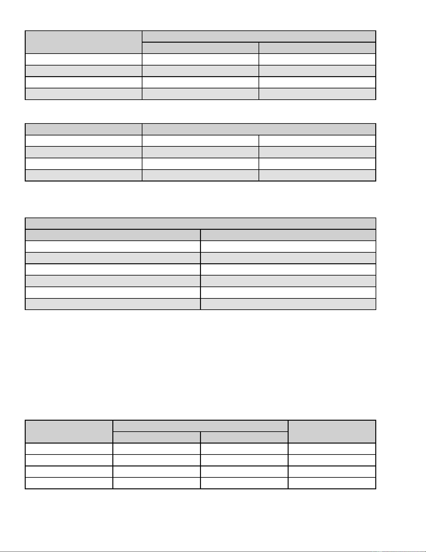
ToroTwinCylinderEngineReplacement
ToroTwinCylinderEngineRemoval
1.ParkthemachineonalevelsurfaceanddisengagethePTO.Stoptheengine,
waitforallmovingpartstostop,andremovekey.Engagetheparkingbrake.
2.Disconnectthebatterybyremovingthenegativecablerst,thenthepositive
cablefromthebattery.
3.Removetheengineguard.
4.Removethemufer.
5.Removethemowerbelt.
6.Removethehydrostaticdrivebelt.
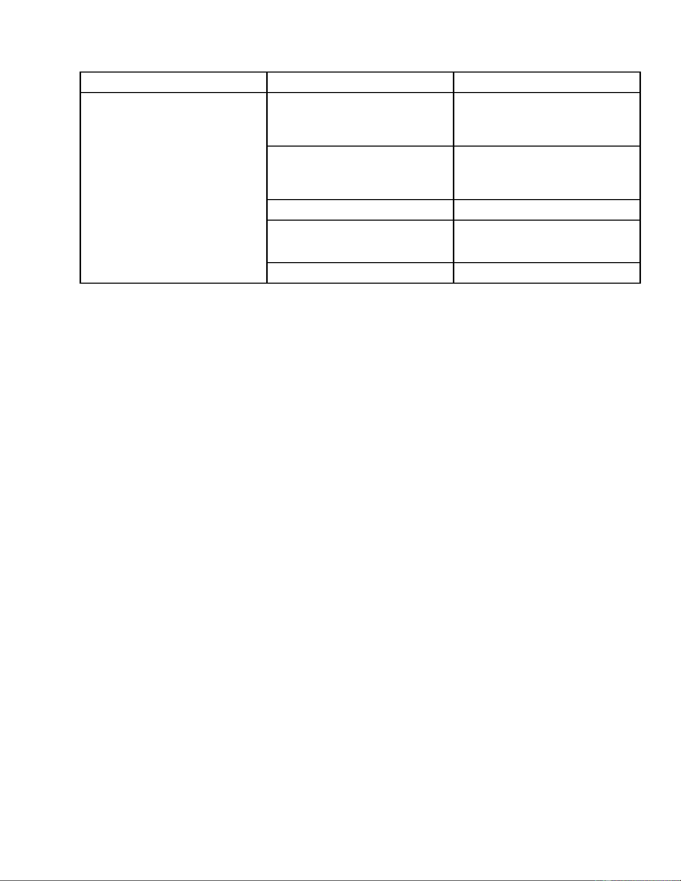
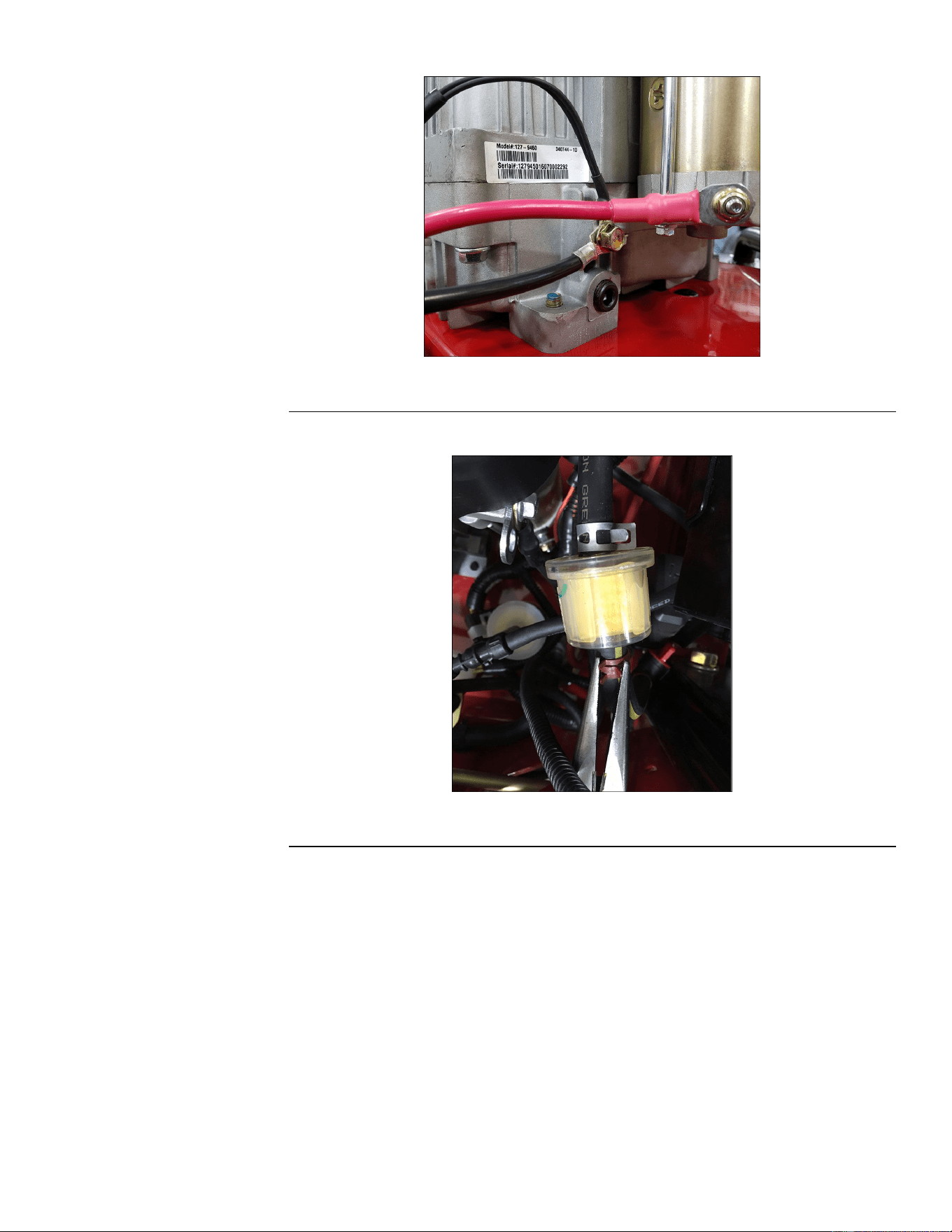
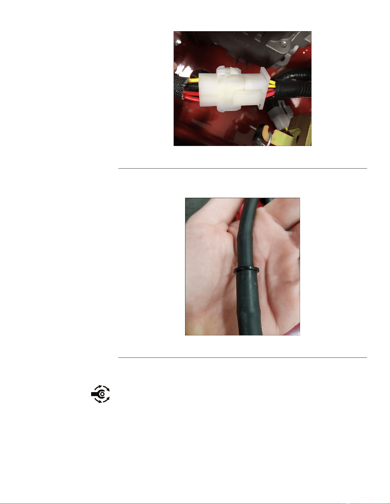
7.Disconnectthechassiswireharnessfromthemainenginewireharness.
g321703
Figure4
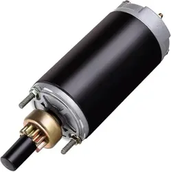
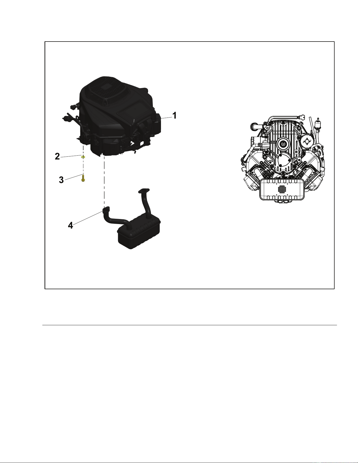
8.Disconnecttheredwirefromthestarter.
g321704
Figure5
9.Disconnecttheblackenginegroundwire.
Engine:ServiceandRepairs
Page4–4
TitanServiceManual
3438-774RevA
ToroTwinCylinderEngineRemoval(continued)
g321706
Figure8
12.Disconnectthethrottlecable.
13.Disconnectthechokecable.
14.Removetheclutchmountingboltandwasher.Slidetheclutchoffofthe
crankshaft.
15.Removetheenginepulley.
16.Removetheenginemountingbolts.
17.Lifttheengineawayfromtheframe.
ToroTwinCylinderEngineInstallation
1.Preparetheframeandsecureanyfuellinesorwireharnesscomponents.
2.Lowertheengineontotheframe.
3.Alignthefourholesoftheenginebasetotheframeandattachthe2rear
mountingboltsandtwoatwashersloosely.
Note:ApplyLoctite243toenginemountingbolts.
4.Attachthefrontboltthroughtheclutchanchorandintotheenginebase.
Engine:ServiceandRepairs
Page4–6
TitanServiceManual
3438-774RevA
ToroTwinCylinderEngineInstallation(continued)
g321707
Figure9
5.Installthe3remainingenginebolts.
6.Torquethe4enginemountingboltsto52±5.8N•m(450±50in-lb).
7.Applyanti-seizetotheclutchendofthecrankshaft.
8.Installtheenginepulleyontothecrankshaft.
9.Installtheclutchontothecrankshaftensuringthattheslotintheclutchaligns
withthetabontheclutchanchor.
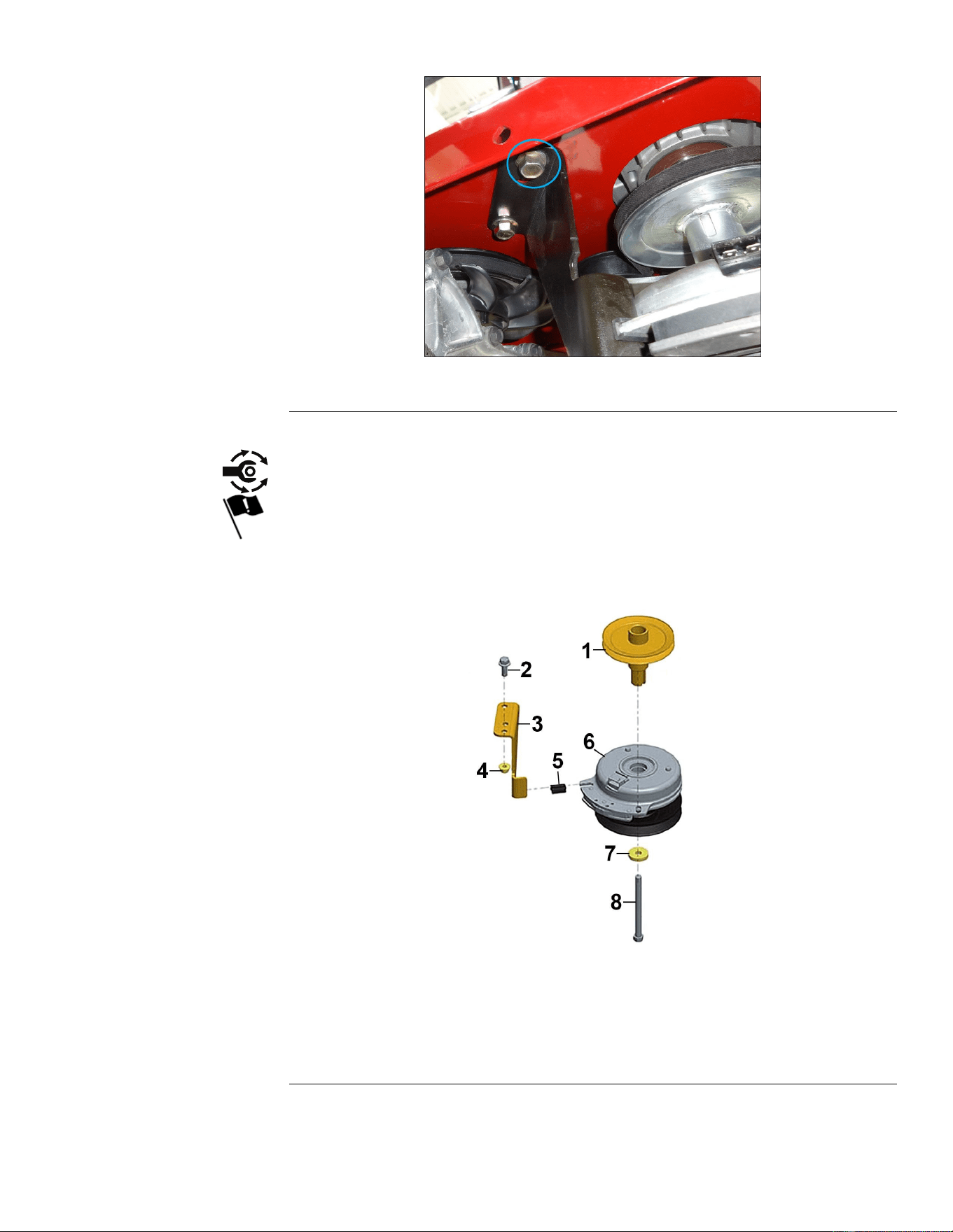
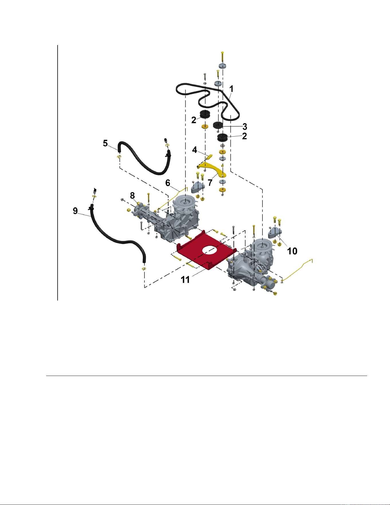
g212682
Figure10
1.EnginePulley
5.ClutchIsolator
2.Screw6.PTOClutch
3.ClutchStop
7.Washer
4.FlangeNut
8.ClutchBolt
10.Installthewasherandclutchbolt.
Note:ApplyLoctitetotheclutchbolt.
TitanServiceManual
Page4–7
Engine:ServiceandRepairs
3438-774RevA
ToroTwinCylinderEngineInstallation(continued)
11.T orquetheclutchboltto69-83N•m(50-60ft-lb).
12.Connectthechokecable.
13.Connectthethrottlecable.
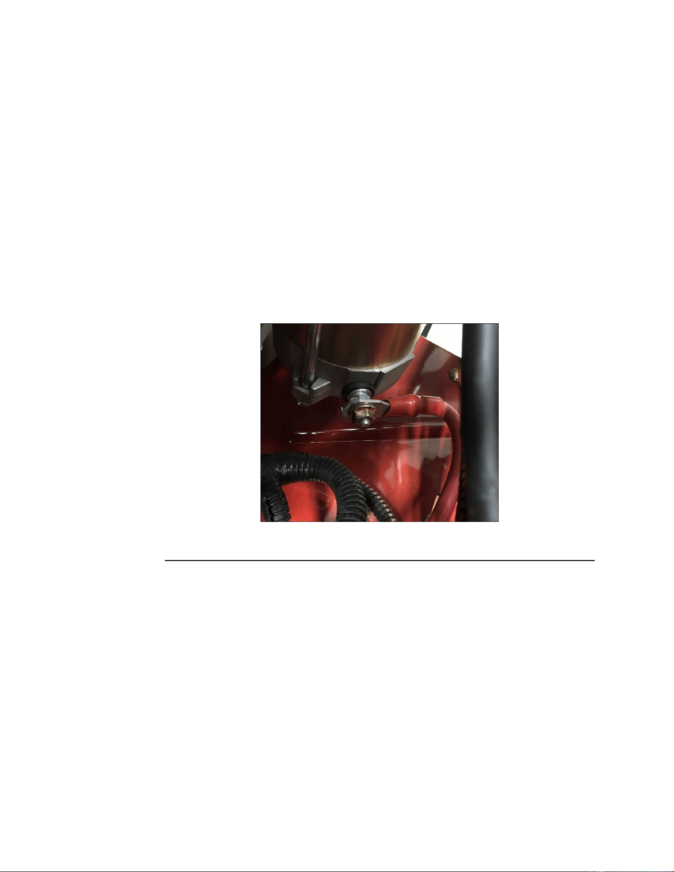
14.Connecttheblackenginegroundwire.
Note:ApplyLoctitetogroundbolt.
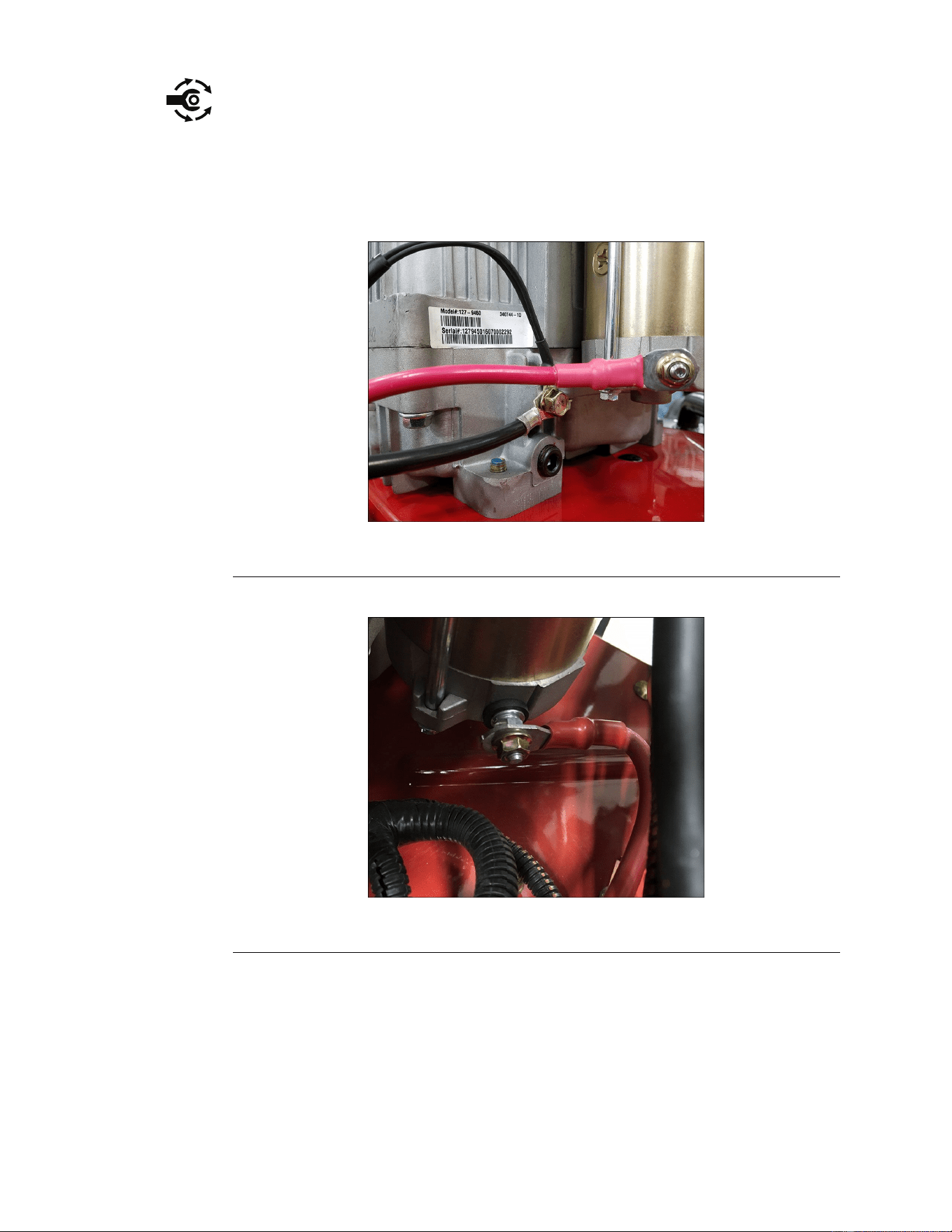
g321702
Figure11
15.Connecttheredwiretothestarter.
g321704
Figure12
16.Connectthechassiswireharnesstothemainenginewireharness.
Engine:ServiceandRepairs
Page4–8
TitanServiceManual
3438-774RevA
ToroTwinCylinderEngineInstallation(continued)
g321703
Figure13
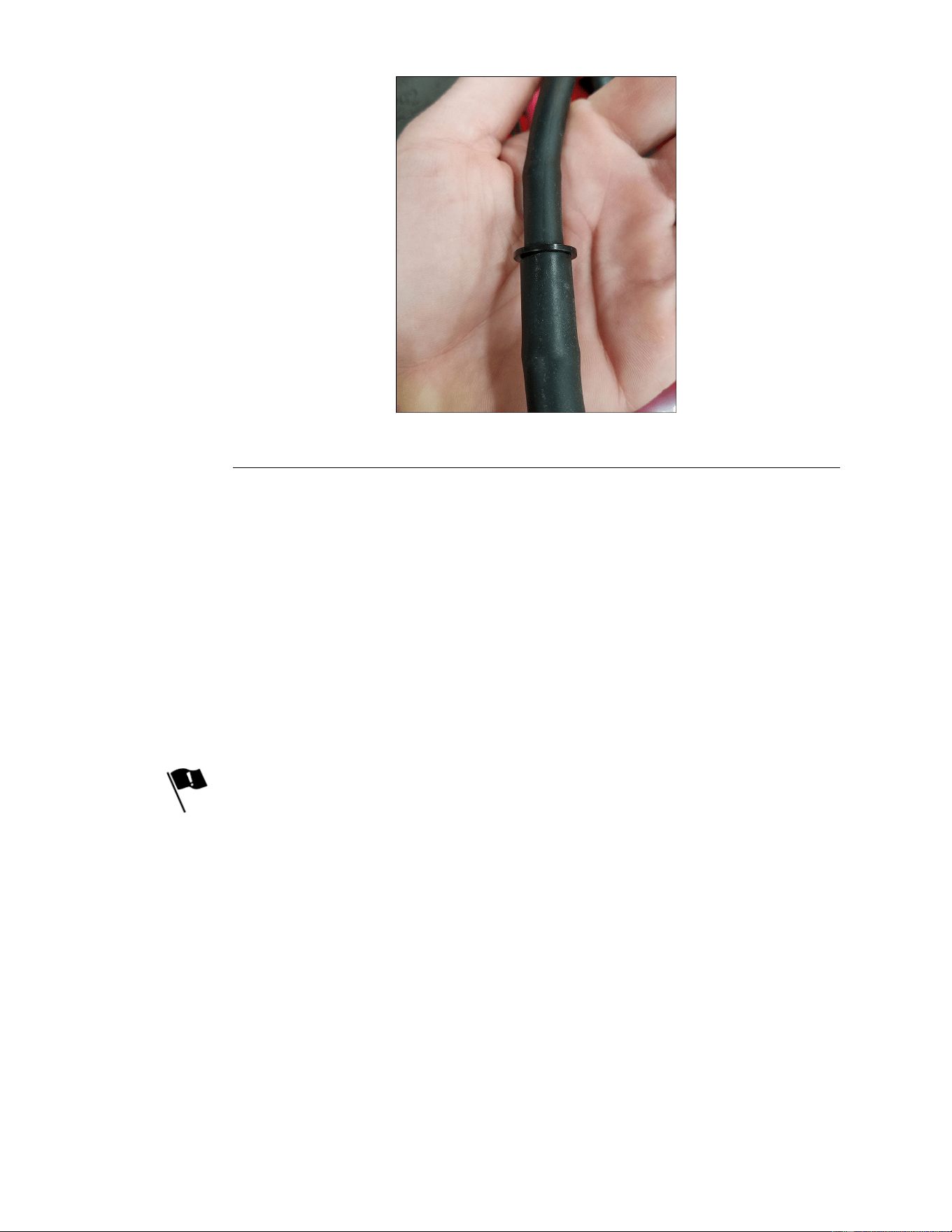
17.Connectthefuelsupplylinetothefuelpump.
18.Connecttheventlinetobarb/splice.
g321706
Figure14
19.Installthehydrostaticdrivebelt.
20.Installthemowerbelt.
21.Installthemuferandnewexhaust.
Note:Torquemufermountingboltsornutsto17-20N•m(150-170in-lb).
22.Installtheengineguard.
23.Fillcrankcasewithapprovedoilandverifyproperoillevel.
24.Connectthebatterybyinstallingthepositivecablerst,thenthenegative
cabletothebattery.
25.Lowertheunitandverifyproperfunction.
TitanServiceManual
Page4–9
Engine:ServiceandRepairs
3438-774RevA
ToroTwinCylinderEngineInstallation(continued)
Note:VerifyEnginespeedissettoproperRPMspecicationforthe
applicablemodel.
KawasakiEngineReplacement
KawasakiEngineRemoval
1.ParkthemachineonalevelsurfaceanddisengagethePTO.Stoptheengine,
waitforallmovingpartstostop,andremovekey.Engagetheparkingbrake.
2.Disconnectthebatterybyremovingthenegativecablerst,thenthepositive
cablefromthebattery.
3.Removetheengineguard.
4.Removethemufer.
5.Removethemowerbelt.
6.Removethehydrostaticdrivebelt.
7.Disconnectthechassiswireharnessfromthemainenginewireharness.
8.Disconnecttheredwirefromthestarter.
g321704
Figure15
9.Disconnecttheblackenginegroundwire.
10.Disconnectthefuelsupplylineatthefuellter.
11.RemoveventlineatsplicewithT orosuppliedhose.
12.Disconnectthethrottlecable.
13.Disconnectthechokecable.
14.Removetheclutchmountingboltandwasher.Slidetheclutchoffofthe
crankshaft.
15.Removetheenginepulley.
16.Removetheenginemountingbolts.
17.Lifttheengineawayfromtheframe.
KawasakiEngineInstallation
1.Preparetheframeandsecureanyfuellinesorwireharnesscomponents.
2.Lowertheengineontotheframe.
Engine:ServiceandRepairs
Page4–10
TitanServiceManual
3438-774RevA
KawasakiEngineInstallation(continued)
3.Alignthefourholesoftheenginebasetotheframeandattachthetworear
mountingboltsandtwoatwashersloosely.
Note:ApplyLoctite243toenginemountingbolts.
4.Attachthefrontboltthroughtheclutchanchorandintotheenginebase.
5.Installthe3remainingenginebolts.
6.Torquethe4enginemountingboltsto52±5.8N•m(450±50in-lb).
7.Applyanti-seizetotheclutchendofthecrankshaft.
8.Installtheenginepulleyontothecrankshaft.
9.Installtheclutchontothecrankshaftensuringthattheslotintheclutchaligns
withthetabontheclutchanchor.
10.Installthewasherandclutchbolt.
Note:ApplyLoctitetotheclutchbolt.
11.T orquetheclutchboltto69-83N•m(50-60ft-lb).
12.Connectthechokecable.
13.Connectthethrottlecable.
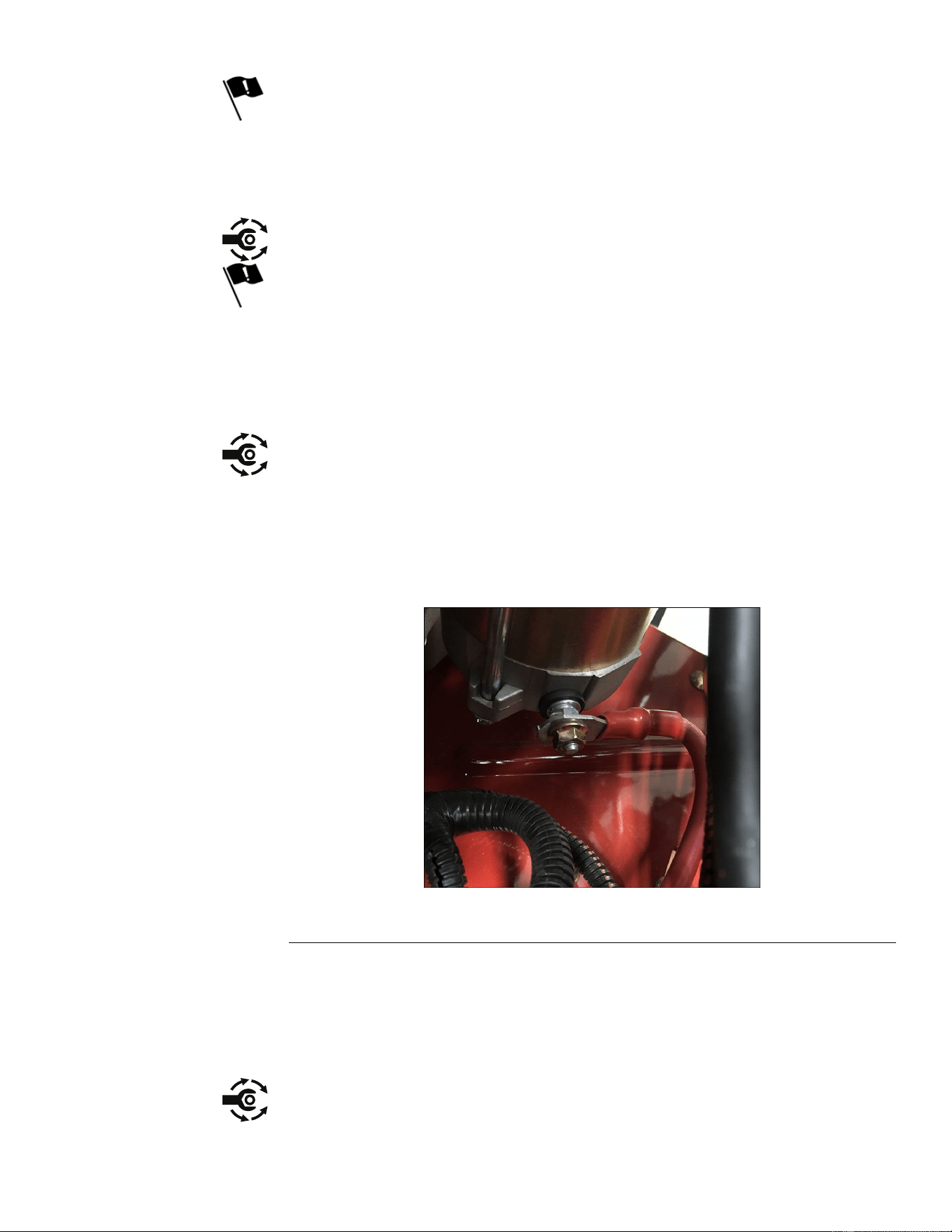
14.Connecttheblackenginegroundwire.
Note:ApplyLoctitetogroundbolt.
15.Connecttheredwiretothestarter.
g321704
Figure16
16.Connectthechassiswireharnesstothemainenginewireharness.
17.Connectthefuelsupplylinetothefuelpump.
18.Connecttheventlinetobarb/splice.
19.Installthehydrostaticdrivebelt.
20.Installthemowerbelt.
21.Installthemuferandnewexhaust.
Note:Torquemufermountingboltsornutsto17-20N•m(150-170in-lb).
TitanServiceManual
Page4–11
Engine:ServiceandRepairs
3438-774RevA

KawasakiEngineInstallation(continued)
22.Installtheengineguard.
23.Fillcrankcasewithapprovedoilandverifyproperoillevel.
24.Connectthebatterybyinstallingthepositivecablerst,thenthenegative
cabletothebattery.
25.Lowertheunitandverifyproperfunction.
Note:VerifyenginespeedissettoproperRPMspecicationforthe
applicablemodel.
Engine:ServiceandRepairs
Page4–12
TitanServiceManual
3438-774RevA

Chapter5
Chassis
TableofContents
GeneralInformation..............................................................................................................................5–2
ServiceandRepairs.............................................................................................................................5–3
CasterAssemblyandBearingReplacement......................................................................................5–5
CasterWheelBearingReplacement..................................................................................................5–5
LeftConsoleReplacement.................................................................................................................5–6
RightConsoleReplacement..............................................................................................................5–8
SeatReplacement(zxModelsOnly)................................................................................................5–11
SeatandMyRIDE™PlatformReplacement(MRModelsOnly)........................................................5–13
FuelT ankReplacement...................................................................................................................5–18
ThrottleControlAssemblyReplacement..........................................................................................5–20
ChokeControlAssemblyReplacement............................................................................................5–22
ParkBrakeHandleAssemblyReplacement.....................................................................................5–24
MotionControlAssemblyReplacement...........................................................................................5–26
TitanServiceManual
Page5–1
Chassis
3438-774RevA

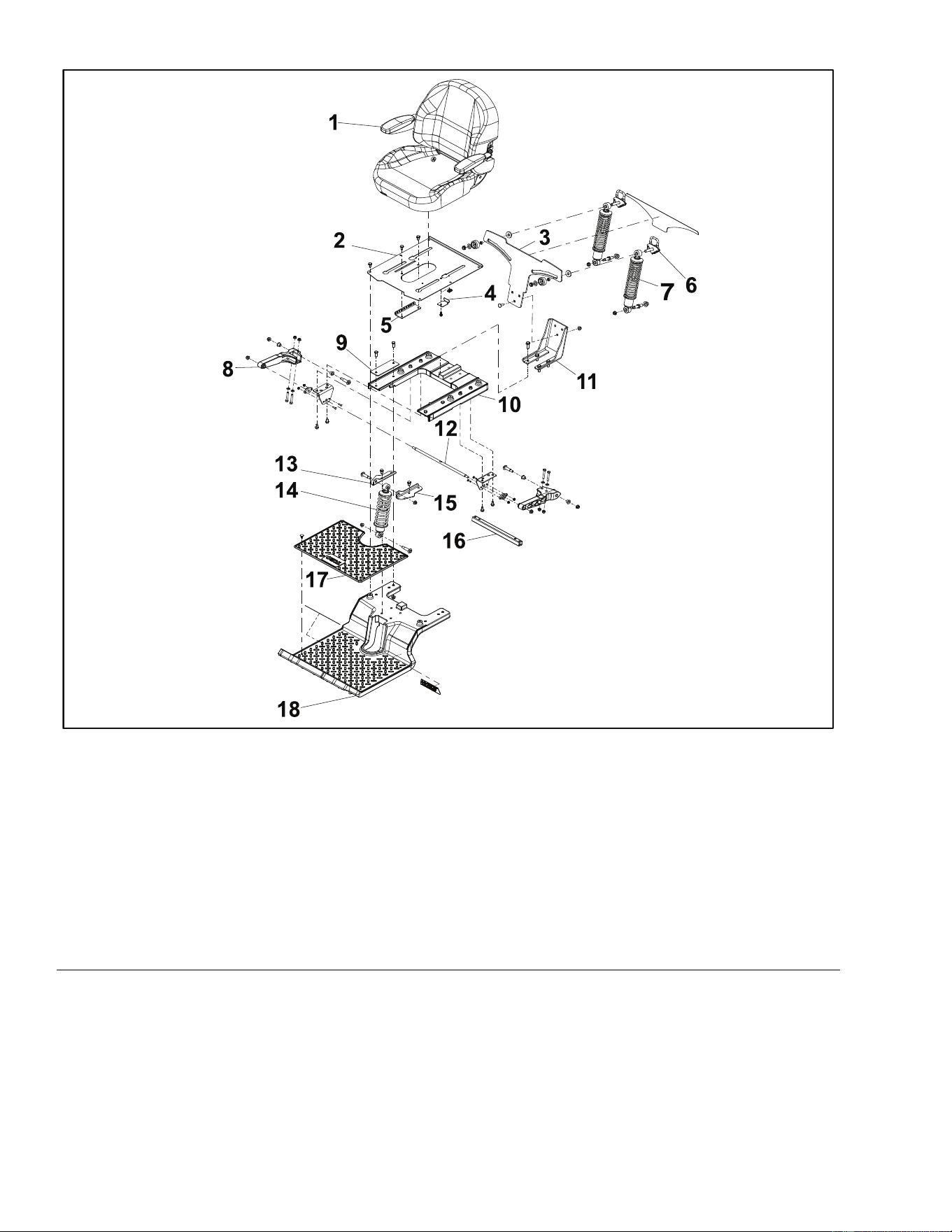
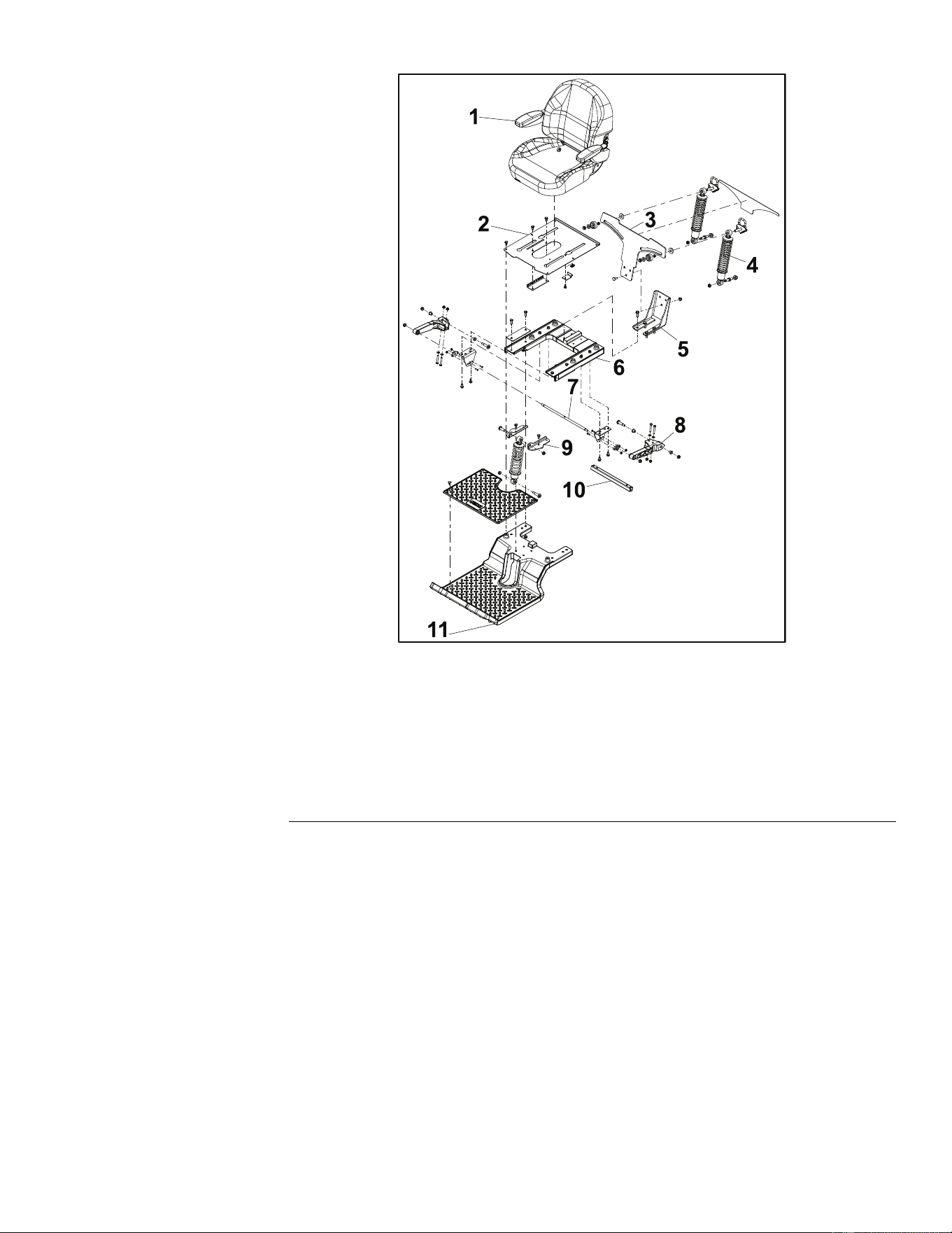
SeatAssembly
g330049
Figure18
1.SeatAsm10.RearSubframe
2.SeatPan
11.LowerMountBracket
3.ShockMountingBracket
12.PivotRod
4.SeatStopBracket13.UpperShockMountBracket
5.SeatLatchBracket14.Shock/SpringAsm
6.CamLockAsm15.UpperShockMountBracket
7.Shock/SpringAsm
16.TrailingArmTube
8.TrailingArm17.Floormat
9.BackerPlate
18.FrontSubframe
Chassis:ServiceandRepairs
Page5–4
TitanServiceManual
3438-774RevA

CasterAssemblyandBearingReplacement
CasterAssemblyandBearingRemoval
1.ParkthemachineonalevelsurfaceanddisengagethePTO.Stoptheengine,
waitforallmovingpartstostop,andremovekey.Engagetheparkingbrake.
2.Disconnectthebatterybyremovingthenegativecablerst,thenthepositive
cablefromthebattery.
3.Raiseandsupporttheunitsothatthefrontwheelsareofftheground,block
rearwheels.
4.Removethecastercap.
5.Supporttheundersideofthecasterwheelandremovethescrewsecuring
thecasterbearingassembly.
6.Removethecasterforkfromthefrontaxle.Inspectthecasterforkshaft
forwearordamage.
7.Removetheupperandlowerbearingsfromtheaxleandinspecttheinsideof
theaxlebearingareafordamageorexcessivewear.
Note:Thebearingsarepressedinandcannotbereused.
CasterAssemblyandBearingInstallation
1.Cleanthesurfaceinsidetheaxlebearingarea,keepingsurfacecleanof
debris.
2.Usingaproperbearinginstallationtool,installanewlowerbearingfromthe
bottomsideintotheaxle,makingsurethatitisfullyseated.
3.Usingaproperbearinginstallationtool,installanewupperbearingfromthe
topsideintotheaxle,makingsurethatitisfullyseated.
Note:Thebearingsaresealedanddonotrequiregrease/lubrication.
4.Applyanti-seizetoforkshaftbeforeinstalling.
5.Installthecasterfromthebottomsideoftheframeandplaceatwasher
ontopofthebearing.
6.Installfastenerandtightentothecastershaft.
7.Installthecastercap.
8.Connectthebatterybyinstallingthepositivecablerst,thenthenegative
cabletothebattery.
9.Lowertheunitandverifyproperfunction.
CasterWheelBearingReplacement
CasterWheelBearingRemoval
1.ParkthemachineonalevelsurfaceanddisengagethePTO.Stoptheengine,
waitforallmovingpartstostop,andremovekey.Engagetheparkingbrake.
2.Disconnectthebatterybyremovingthenegativecablerst,thenthepositive
cablefromthebattery.
3.Raiseandsupporttheunitsothatthefrontwheelsareofftheground,block
rearwheels.
4.Removetheboltandnutsecuringthecasterwheeltothecasterfork.
5.Lowerthecasterwheelawayfromthecasterfork.
6.Removethedustcaps,feltwashers,andwheelspanner.
7.Removethebearings(bearingsmayhaveaslightpresst).
TitanServiceManual
Page5–5
Chassis:ServiceandRepairs
3438-774RevA
CasterWheelBearingInstallation
1.Installnewbearings(bearingsmayhaveaslightpresst).
Note:Thebearingsaresealedanddonotrequiregrease/lubrication.They
mayalsohaveaslightpresst.
2.Installthespannerintothecasterwheel,theninstallfeltwashersanddust
capsoverthecasterbearings.
3.Placethecasterwheelinsideofthecasterfork,aligningthespannerwith
theholesinthecasterfork.
4.Installtheboltandnutandtorqueto44±7N•m(32±5ft-lb).
5.Lowertheunitandverifyproperfunction.
6.Installnewbearings(bearingsmayhaveaslightpresst).
7.Connectthebatterybyinstallingthepositivecablerst,thenthenegative
cabletothebattery.
LeftConsoleReplacement
LeftConsoleRemoval
1.ParkthemachineonalevelsurfaceanddisengagethePTO.Stoptheengine,
waitforallmovingpartstostop,andremovekey.Engagetheparkingbrake.
2.Disconnectthebatterybyremovingthenegativecablerst,thenthepositive
cablefromthebattery.
3.Removethe3(T30)shoulderscrewsfromtheleftconsole.
g321205
Figure19
4.Removethefuelcapanddisconnectthekeeperline.
Chassis:ServiceandRepairs
Page5–6
TitanServiceManual
3438-774RevA
LeftConsoleRemoval(continued)
g321206
Figure20
5.Removetheleftsidecontrollever.
6.Lifttheconsoleupwardoffofthemachine.
7.Replacethefuelcap.
LeftConsoleInstallation
1.Removethefuelcapfromthegastank.
2.Lowertheconsoleintoplace,ensuringthatitseatsproperlyonthesupports.
g321204
Figure21
3.Installtheleftsidecontrollever.
4.Installthekeeperlineintothefuelcap,andreinstallthefuelcap.
TitanServiceManual
Page5–7
Chassis:ServiceandRepairs
3438-774RevA
LeftConsoleInstallation(continued)
5.Installthe3(T30)shoulderscrewssecuringtheleftconsoletothemachine.
Torquescrewsto11N•m(100in-lb).
g321205
Figure22
6.Installthebatteryontothebatterytrayandsecurewiththebungeestrap
7.Connectthebatterybyinstallingthepositivecablerst,thenthenegative
cabletothebattery.
RightConsoleReplacement
RightConsoleRemoval
1.ParkthemachineonalevelsurfaceanddisengagethePTO.Stoptheengine,
waitforallmovingpartstostop,andremovekey.Engagetheparkingbrake.
2.Disconnectthebatterybyremovingthenegativecablerst,thenthepositive
cablefromthebattery.
3.Removethe3(T30)shoulderscrewsfromtherightconsole.
Chassis:ServiceandRepairs
Page5–8
TitanServiceManual
3438-774RevA
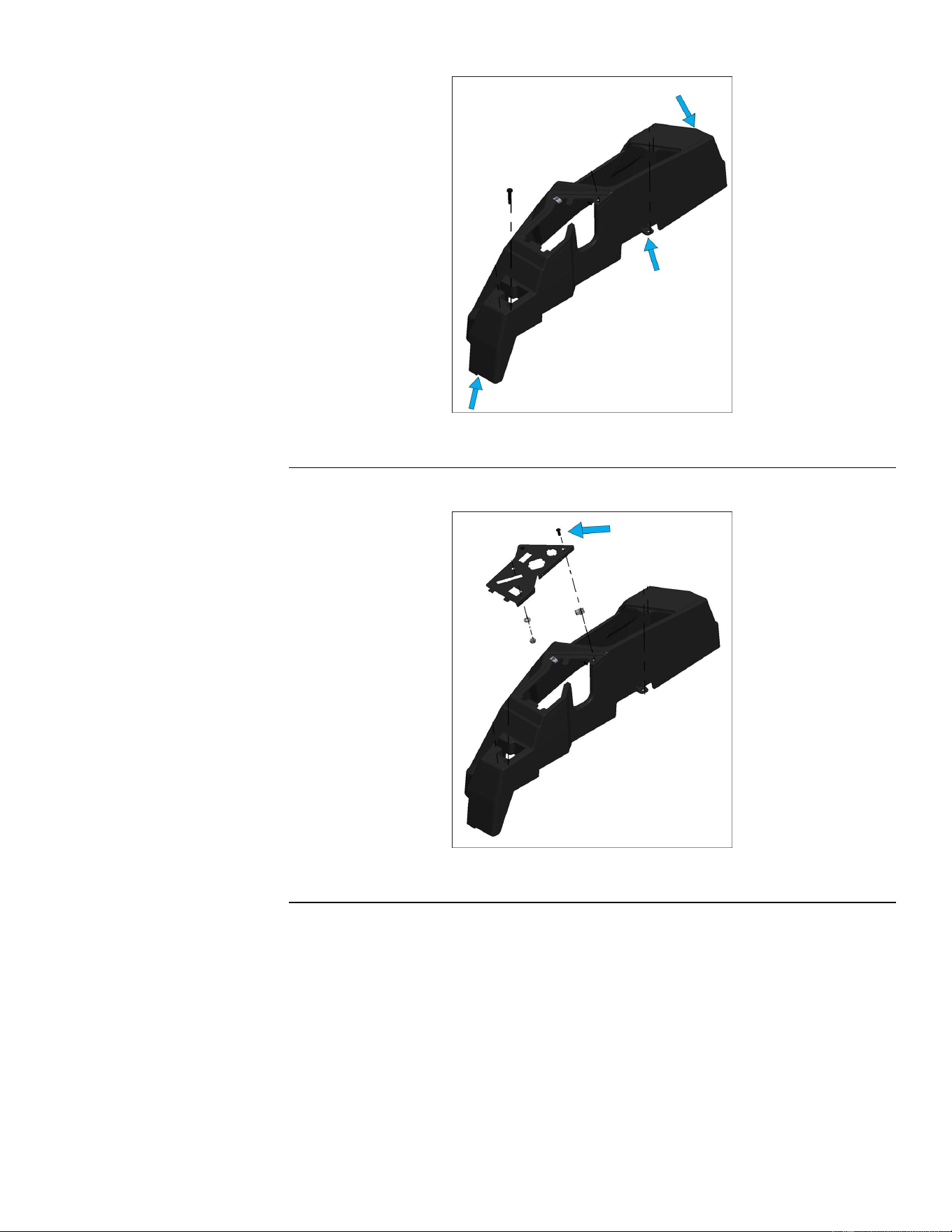
RightConsoleRemoval(continued)
g321208
Figure23
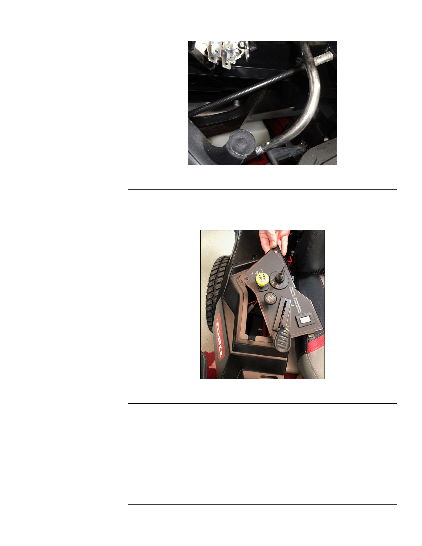
4.Removethescrewssecuringthecontrolpanelassemblytotheconsole.
g321207
Figure24
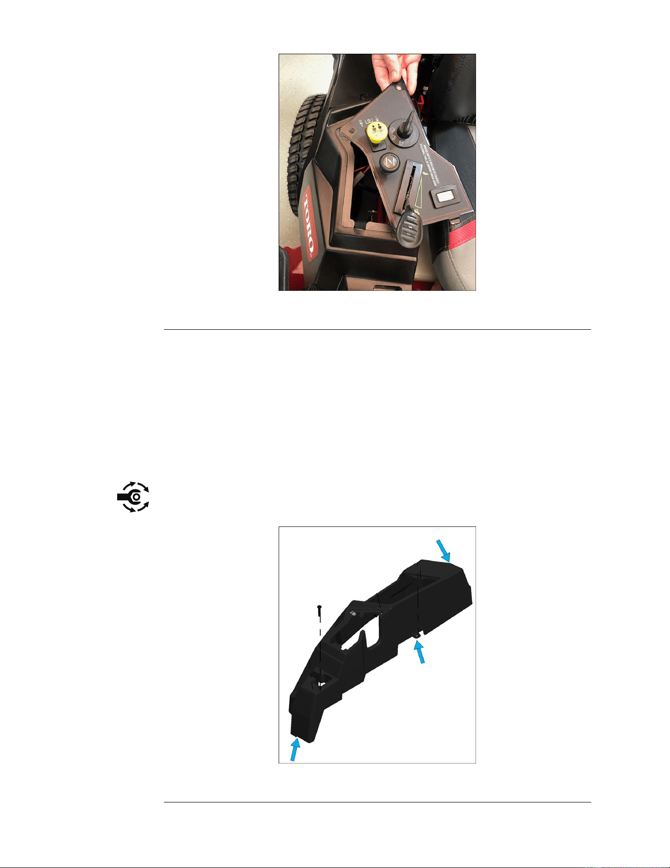
5.Removetherightsidecontrollever.
6.Lifttheconsoleupwardoffofthemachine,whilefeedingthecontrolpanel
assemblythroughtheopeningintheconsole.
Note:Thecontrolpanelassemblyshouldbesupportedwhileservicingthe
machine,toavoiddamagetothecablesorwireharness.
TitanServiceManual
Page5–9
Chassis:ServiceandRepairs
3438-774RevA
RightConsoleRemoval(continued)
g322343
Figure25
RightConsoleInstallation
1.Lowertheconsoleintoplace,whilemovingthecontrolpanelassembly
throughtheopeningintheconsoleandintoposition.Ensurethattheconsole
seatsproperlyonthesupports.
Note:Beforesecuringthecontrolpaneltotheconsole,ensurethatallcables
andelectricalconnectionsareseatedrmlyinplaceontheundersideof
thecontrolpanelassembly.
2.Securethecontrolpanelassemblytotheconsole.
3.Installthe3(T30)shoulderscrewssecuringtherightconsoletothemachine.
Torquescrews11N•m(100in-lb).
g321208
Figure26
Chassis:ServiceandRepairs
Page5–10
TitanServiceManual
3438-774RevA
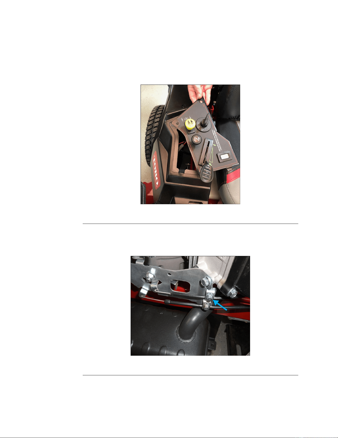
SeatRemoval(ZXModelsOnly)
1.ParkthemachineonalevelsurfaceanddisengagethePTO.Stoptheengine,
waitforallmovingpartstostop,andremovekey.Engagetheparkingbrake.
2.Disconnectthebatterybyremovingthenegativecablerst,thenthepositive
cablefromthebattery.
3.Disconnectthewireharnessconnectorattheoperatorpresenceswitch.
4.Removethecotterpinsfromthestoprodontheleftandrightsidesofthe
seat.
5.Slidetherodtowardtheinsideoftheseatpantoreleasetheseatfromthe
frame,thenslideittheoppositewaytoreleaseitfromtheotherside.
6.Lifttheseatassemblyoffofthemachine.
SeatInstallation(ZXModelsOnly)
1.Verifythatthefueltankholddownisseatedproperlyinthefrontandrearof
theframeandsecuredwiththeholddownbolt.
g321203
Figure28
2.Placetheseatontopofthefueltankandaligntheholeinonesideofthe
framewiththeholeintheseatplate.
3.Installthestoprodandsecurewithonecotterpin.
4.Slidetherodtowardtheoutsideofthemachinewhilealigningtheholeonthe
oppositesidewiththeholeintheframe.
5.Insertthestoprodtosecuretheseatinplaceandinstallthecotterpin.
6.Raisetheseatandconnectthewireharnessterminaltotheoperator
presenceswitch.
7.Liftandlowertheseattoverifyproperfunctionoftheseatpivotsandthe
seatlatch.
8.Connectthebatterybyinstallingthepositivecablerst,thenthenegative
cabletothebattery.
9.Verifyproperfunctionoftheunit.
Chassis:ServiceandRepairs
Page5–12
TitanServiceManual
3438-774RevA
SeatandMyRIDE™Platform(MRModelsOnly)Removal
1.ParkthemachineonalevelsurfaceanddisengagethePTO.Stoptheengine,
waitforallmovingpartstostop,andremovekey.Engagetheparkingbrake.
2.Disconnectthebatterybyremovingthenegativecablerst,thenthepositive
cablefromthebattery.
3.Removetherightandleftsideconsoles.LeftConsoleReplacement(page
5–6)RightConsoleReplacement(page5–8)
4.Disconnectthewireharnessconnectorattheoperatorpresenceswitch.
5.Removetherelayandboltattachingrelayandfusetoholderonframe.
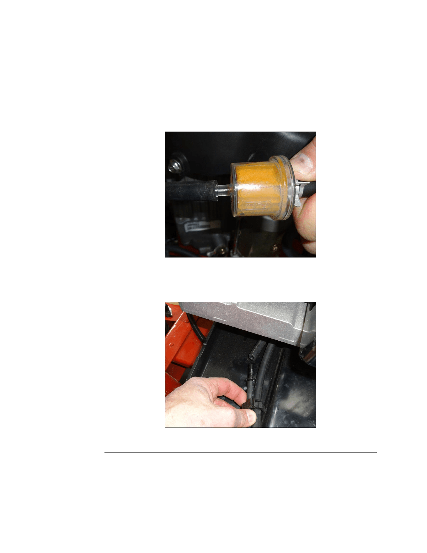
6.Disconnectthefuelsupplylineatthefuellter.
g321211
Figure30
7.Disconnecttheventlineatthesplicetting.
g321202
Figure31
8.Removetheboltandnutsecuringthefrontshock/springassemblytothe
MyRIDE®platform.
Chassis:ServiceandRepairs
Page5–14
TitanServiceManual
3438-774RevA
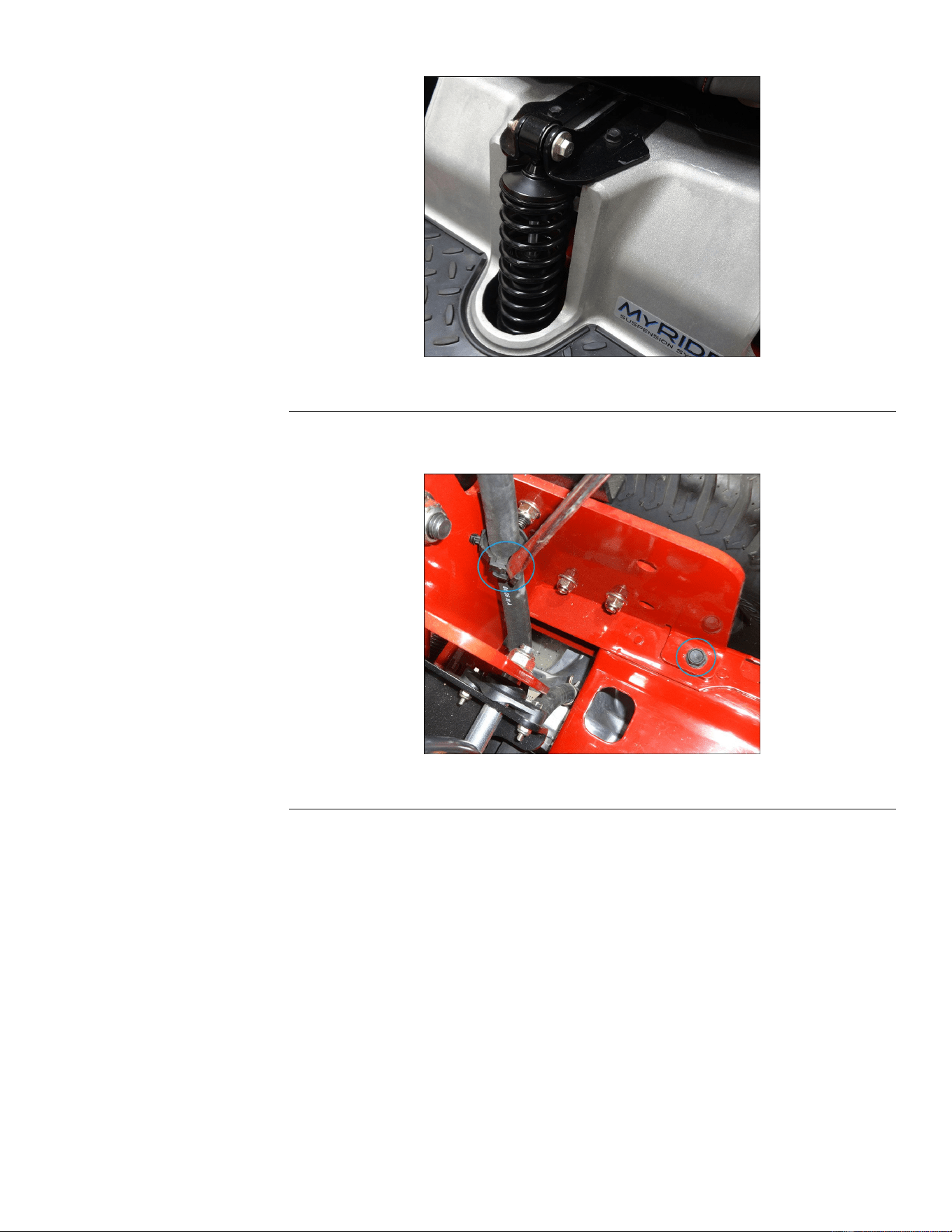
SeatandMyRIDE™Platform(MRModelsOnly)Removal(continued)
g321445
Figure32
9.Removetheself-tappingscrewontheframebracketsoneachsideofthe
machine.Releasetheventhosekeepers.
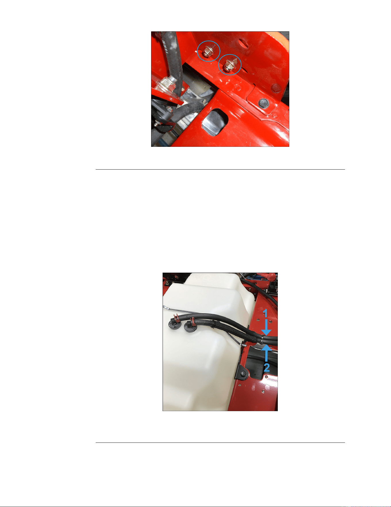
g321448
Figure33
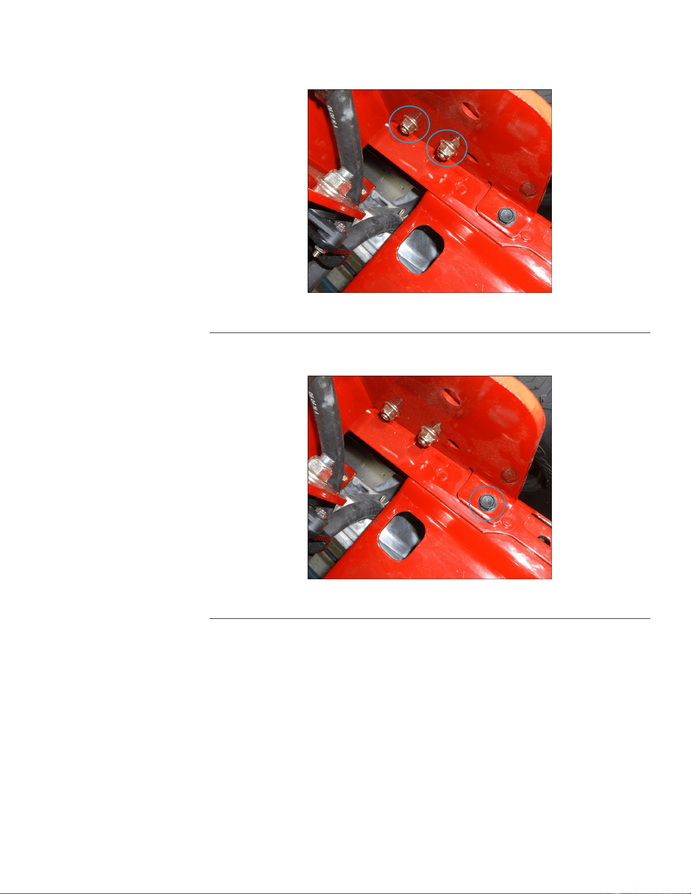
10.Removethe2boltsandnutssecuringtheframebracketstothemainframe
oneachsideofthemachine.
TitanServiceManual
Page5–15
Chassis:ServiceandRepairs
3438-774RevA
SeatandMyRIDE™Platform(MRModelsOnly)Removal(continued)
g321447
Figure34
11.TilttheMyRIDE®assemblyoneway.Unhookthefuellinekeeperfrom
undertheseat.
12.LifttheentireMyRIDE®assemblyupandawayfromthemainframe.
RemovingtheMyRIDE®assemblywilltaketwoormorepeople.
Note:Donotremoveeitheroftheswingarmrodsfromtheswingarm
underneaththemachine.Thiscouldcausedamageormisalignmentofthe
MyRIDE®suspensionplatform.
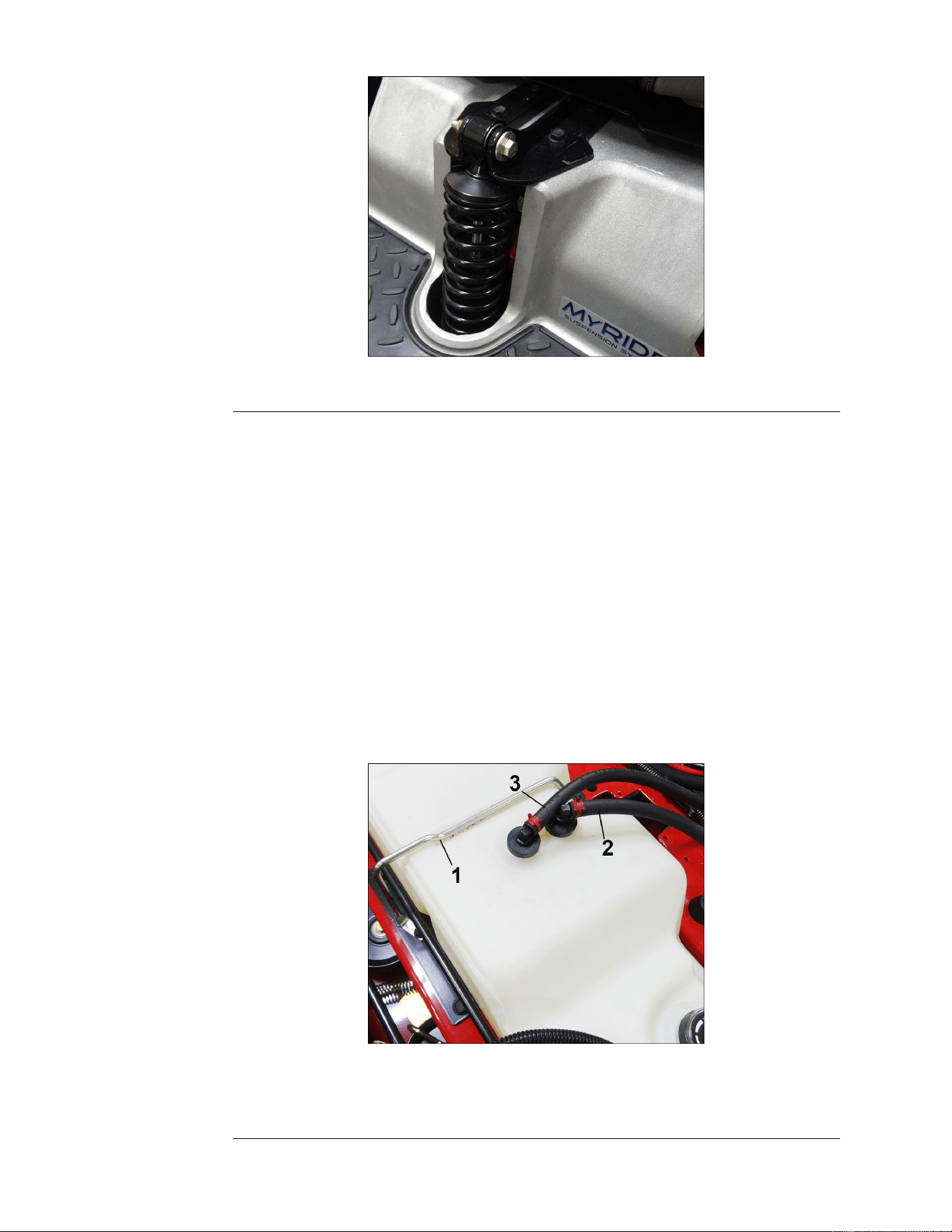
SeatandMyRIDE™Platform(MRModelsOnly)Installation
1.Verifythatthefueltankholddownisseatedproperlyinthefrontandrearof
theframeandsecuredwiththeholddownbolt.
g334861
Figure35
1.VentLine2.LiquidLine
2.LowertheMyRIDE®assemblyontothemainframe,aligningtheframe
bracketsoneachsidewiththematingholesinthemainframe.Reconnect
thefuellinekeeperundertheseat.
Chassis:ServiceandRepairs
Page5–16
TitanServiceManual
3438-774RevA
SeatandMyRIDE™Platform(MRModelsOnly)Installation(continued)
3.Installthe2boltsandnutssecuringtheframebracketstothemainframe
oneachsideofthemachine.
g321447
Figure36
4.Installtheself-tappingscrewontheframebracketoneachsideofthe
machine.
g321446
Figure37
5.Installtheboltandnutsecuringthefrontshock/springassemblytothe
MyRIDE™Platform.
TitanServiceManual
Page5–17
Chassis:ServiceandRepairs
3438-774RevA
SeatandMyRIDE™Platform(MRModelsOnly)Installation(continued)
g321445
Figure38
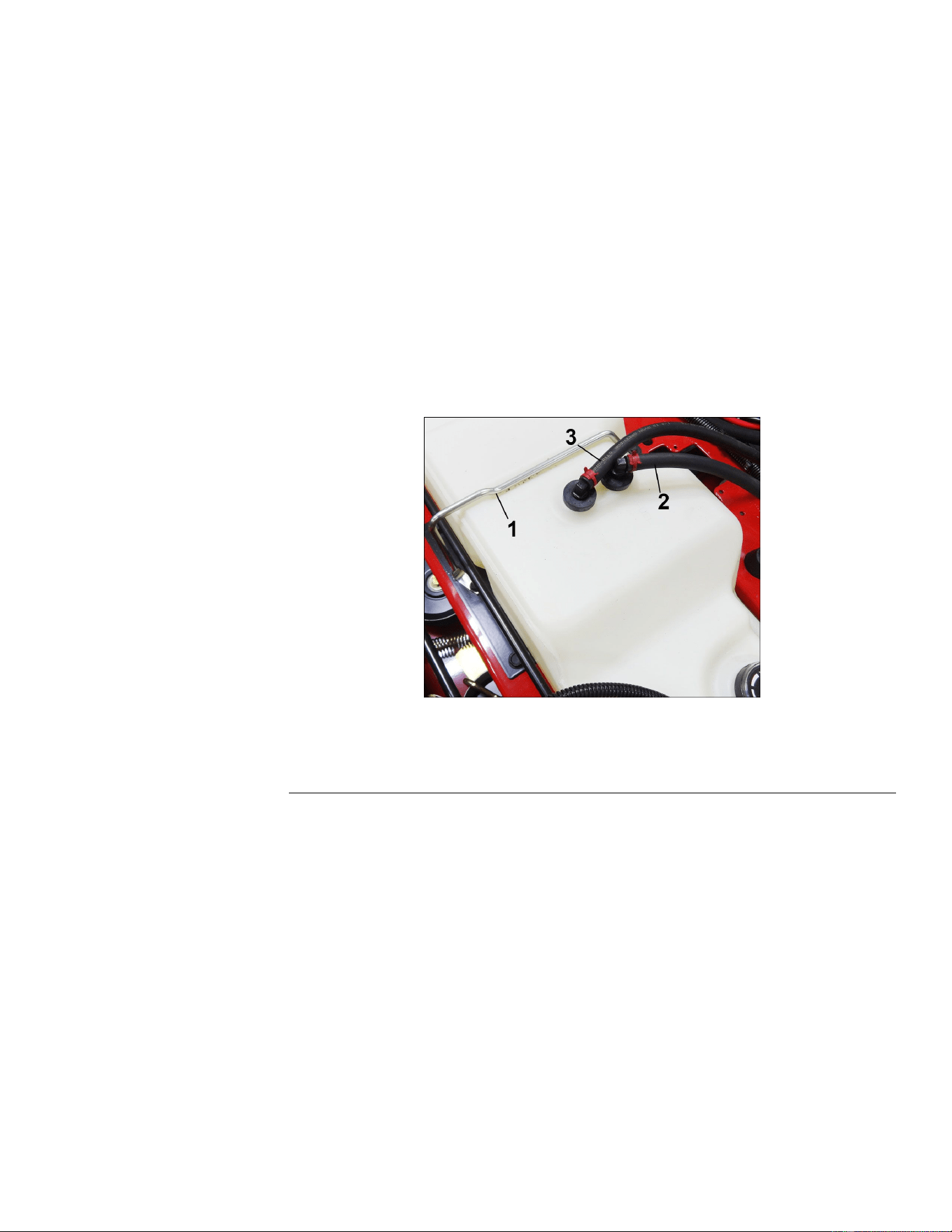
6.Connectthefueltankventlineattothesplicetting.
7.Connectthefuelsupplylinetothefuellter.
8.Connecttheventlinekeeperstotheventlines.
9.Connectthewireharnessterminaltotheoperatorpresenceswitch.
10.Installtherelayandfuseholder.
11.Installtherightandleftsideconsoles.LeftConsoleReplacement(page5–6)
RightConsoleReplacement(page5–8)
12.Connectthebatterybyinstallingthepositivecablerst,thenthenegative
cabletothebattery.
13.Verifyproperfunction.
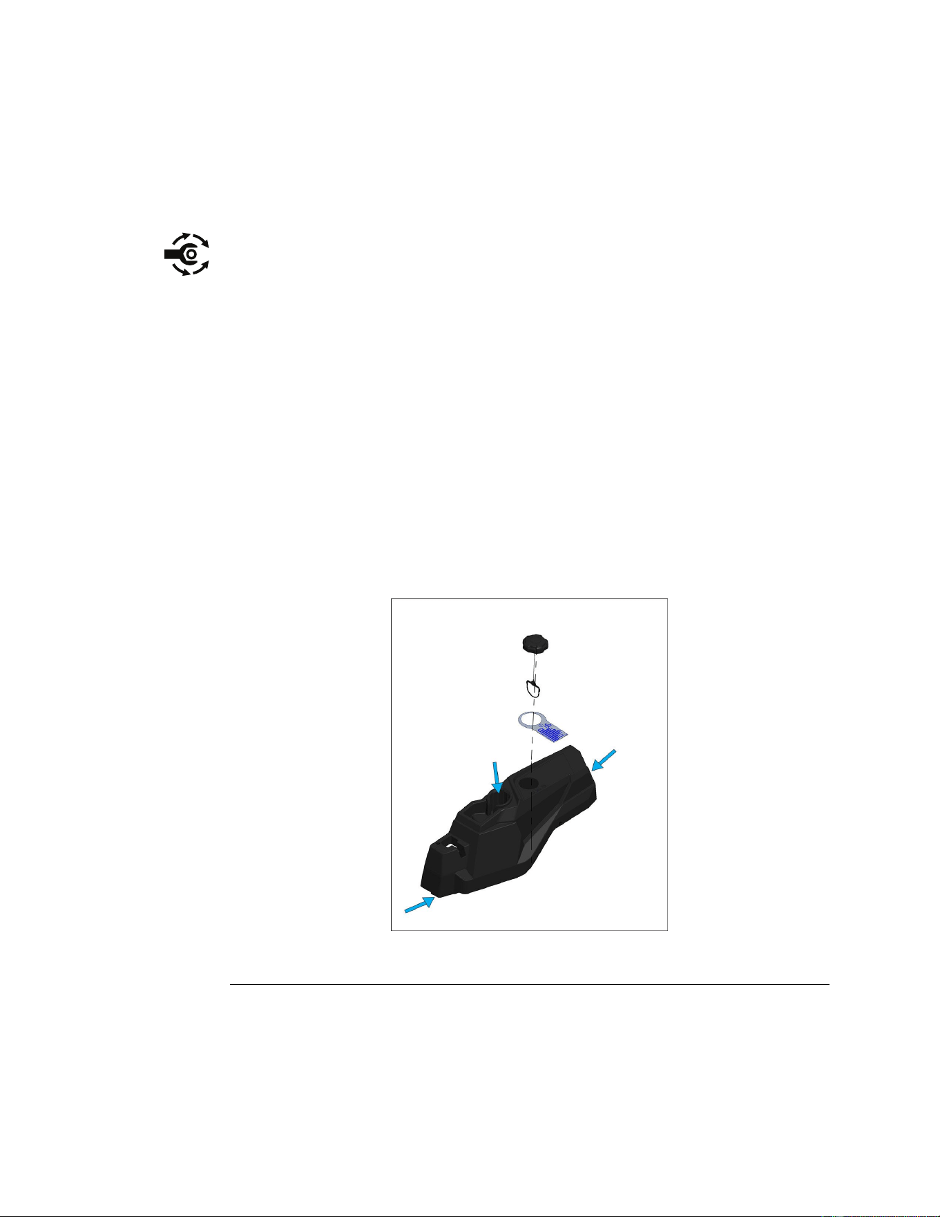
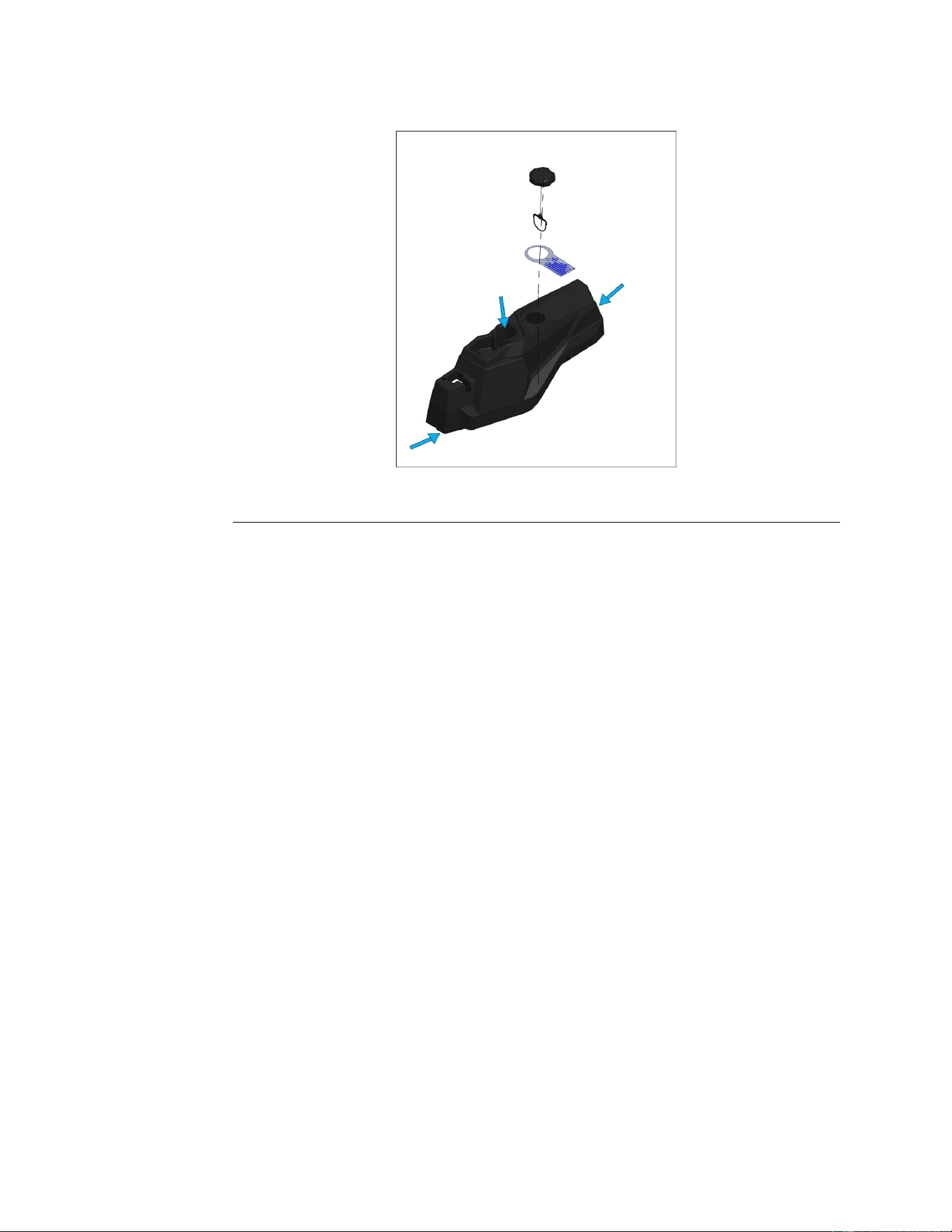
FuelTankReplacement
FuelTankRemoval
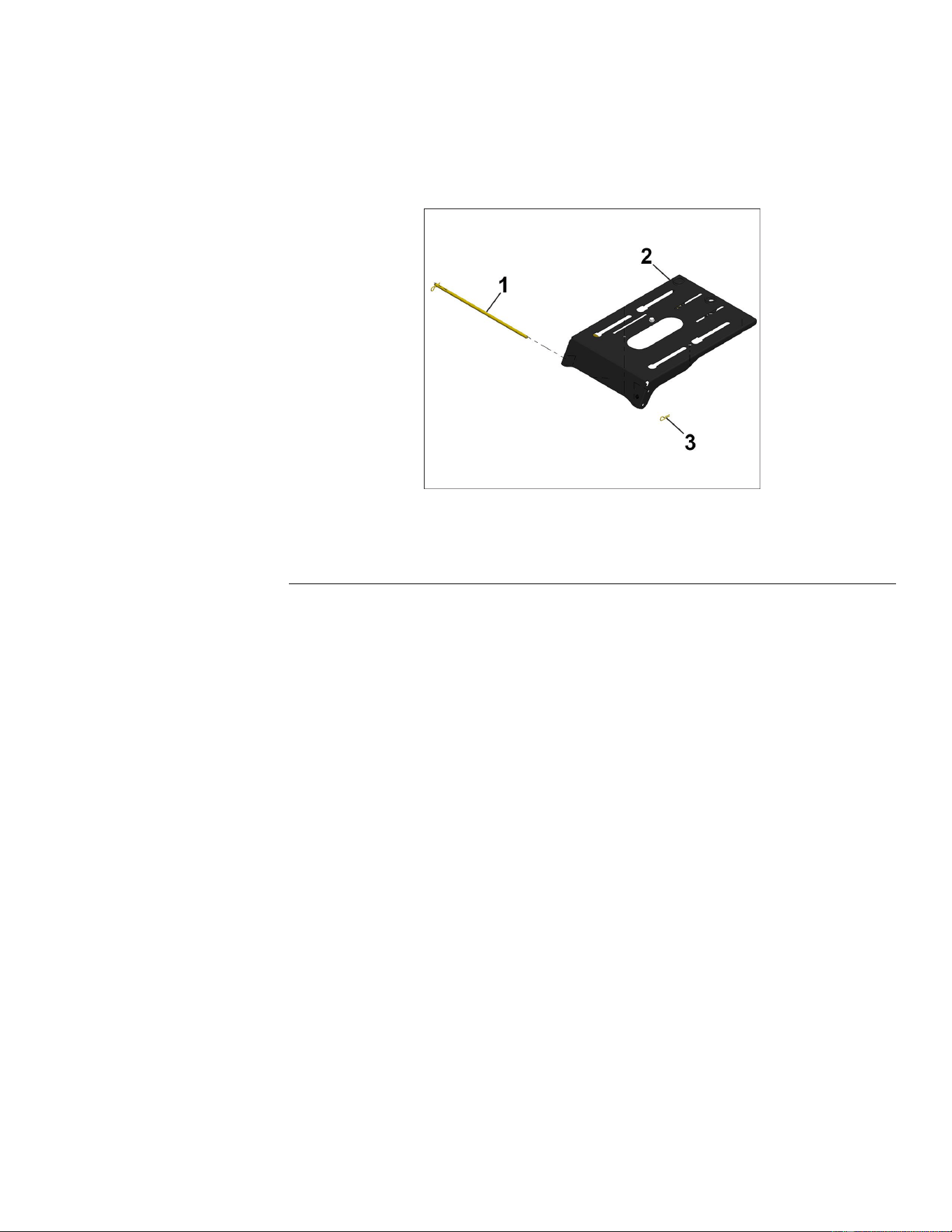
g321450
Figure39
1.FuelTankHold-DownRod3.VentLine
2.FuelSupplyLine
Chassis:ServiceandRepairs
Page5–18
TitanServiceManual
3438-774RevA
FuelTankRemoval(continued)
1.ParkthemachineonalevelsurfaceanddisengagethePTO.Stoptheengine,
waitforallmovingpartstostop,andremovekey.Engagetheparkingbrake.
2.Disconnectthebatterybyremovingthenegativecablerst,thenthepositive
cablefromthebattery.
3.Removetherightandleftconsoles.LeftConsoleReplacement(page5–6)
RightConsoleReplacement(page5–8)
4.Reinstallthefuelcap.
5.Removetheseatassembly(ZXmodels)ortheMyRIDE™PlatformAssembly
(MRmodels).
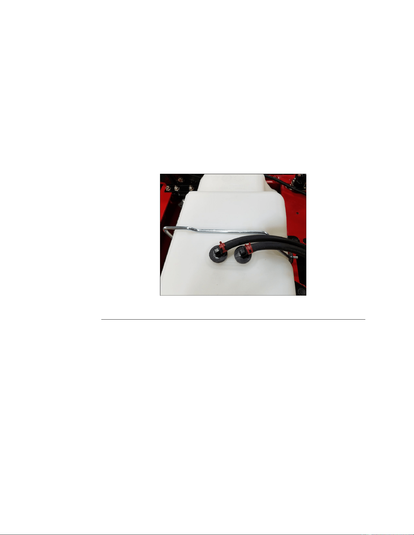
6.Removethefueltankholddownrodandbolt.
7.Disconnectthefuelsupplylineandthebentlinefromthefueltank.
8.Rotateandliftthefueltankassemblyfromthemachine.
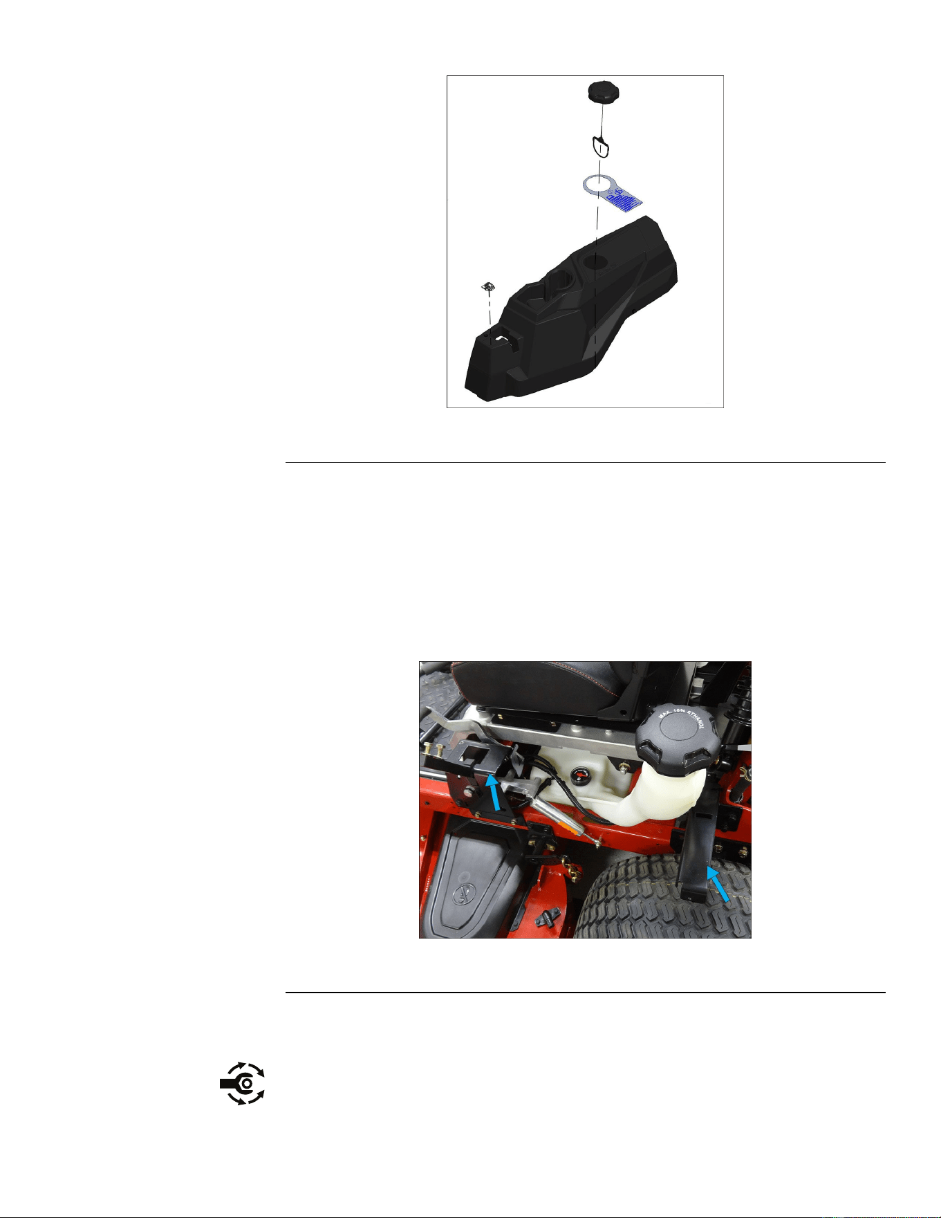
FuelTankInstallation
g321450
Figure40
1.FuelTankHold-DownRod3.VentLine
2.FuelSupplyLine
1.Positionthefueltankassemblyandrotateitontotheframewiththevent
portstowardtherearofthemachine.
2.Connecttheventlinetothefueltank.
3.Connectthefuelsupplylinetothefueltank.
Note:Makesurethatthefuellinesareroutedtowardstheholddownrod
andintherecessofthefueltank.
4.Installthefueltankholddownrodandbolt.
5.Installtheseatassembly.SeatReplacement(zxModelsOnly)(page5–11)
6.Installtherightandleftconsoles.LeftConsoleReplacement(page5–6)
RightConsoleReplacement(page5–8)
7.Installthefuelcapbyslidingthed-ringintotheneckofthefueltank.Secure
thefuelcaptothetank.
8.Connectthebatterybyinstallingthepositivecablerst,thenthenegative
cabletothebattery.
TitanServiceManual
Page5–19
Chassis:ServiceandRepairs
3438-774RevA
ThrottleControlAssemblyReplacement
ThrottleControlAssemblyRemoval
1.ParkthemachineonalevelsurfaceanddisengagethePTO.Stoptheengine,
waitforallmovingpartstostop,andremovekey.Engagetheparkingbrake.
2.Disconnectthebatterybyremovingthenegativecablerst,thenthepositive
cablefromthebattery.
3.Removethecontrolpanelassemblyfromtherightconsole.
g322343
Figure41
4.Prythekeepertabonthethrottlecontrolassemblyandunsnapthecontrol
fromtheconsole.
5.Loosentheclampsecuringthethrottlecabletothethrottleplate(Figure28).
g321451
Figure42
6.Removethethrottlecablefromthethrottleplate,notingthepositionofthe
cableintheplate.
7.Pullthethrottlecableassemblythroughtheconsoleandoutofthemachine.
Chassis:ServiceandRepairs
Page5–20
TitanServiceManual
3438-774RevA
ThrottleControlAssemblyInstallation
1.Routethethrottlecablethroughtherightconsole.
g321452
Figure43
2.Snapthethrottlecontrolassemblyintoplace.
3.Installthecontrolpanelassemblyintotheconsole.
4.Movethethrottlecontrollevertothefullspeedposition.
g322343
Figure44
5.Placethezbendofthethrottlecableinthethrottleplateontheenginein
thepositionpreviouslynoted.
6.Placethecableunderthecableclamp.
7.Ensurethatthethrottlecontrolleverisinthefastidleposition.
Note:Pullonthecableandverifytheengineisatfullthrottle,thentighten
theclamp.
g321453
Figure45
TitanServiceManual
Page5–21
Chassis:ServiceandRepairs
3438-774RevA
ThrottleControlAssemblyInstallation(continued)
8.Connectthebatterybyinstallingthepositivecablerst,thenthenegative
cabletothebattery.
ChokeControlAssemblyReplacement
ChokeControlAssemblyRemoval
1.ParkthemachineonalevelsurfaceanddisengagethePTO.Stoptheengine,
waitforallmovingpartstostop,andremovekey.Engagetheparkingbrake.
2.Disconnectthebatterybyremovingthenegativecablerst,thenthepositive
cablefromthebattery.
3.Loosentheclampsecuringthechokecabletothechokeplateontheengine.
g323084
Figure46
4.Removethechokecablefromtheplate,notingthepositionofthecable
intheplate.
5.Removethecontrolpanelassemblyfromtherightconsole.
6.Onthebottomsideofthecontrolpanelassembly,loosenthejamnut
securingthechokeleverinplace.Removethenutfromthechokecable.
7.Pullthechokecableassemblythroughthecontrolpanelassemblyandout
ofthemachine.
ChokeControlAssemblyInstallation
1.Routethechokecablethroughthecontrolpanelassembly
2.Threadthejamnutoverthechokecableuptothecontrolpanel.
Chassis:ServiceandRepairs
Page5–22
TitanServiceManual
3438-774RevA
ChokeControlAssemblyInstallation(continued)
g321454
Figure47
3.Attachthechokecableassemblytothecontrolpanelwiththejamnut.
4.Installthecontrolpanelassemblyintotheconsole.
5.Movethechokecontrollevertotheopenposition(down).
6.Placethezbendofthechokecableinthechokeplateontheengineinthe
positionpreviouslynoted.
7.Placethecableunderthecableclamp.
8.Ensurethatthechokecontrolleverispresseddownfullyandtightenthe
cableclamp.
g323084
Figure48
9.Connectthebatterybyinstallingthepositivecablerst,thenthenegative
cabletothebattery.
TitanServiceManual
Page5–23
Chassis:ServiceandRepairs
3438-774RevA
ParkBrakeHandleAssemblyReplacement
ParkBrakeHandleAssemblyRemoval
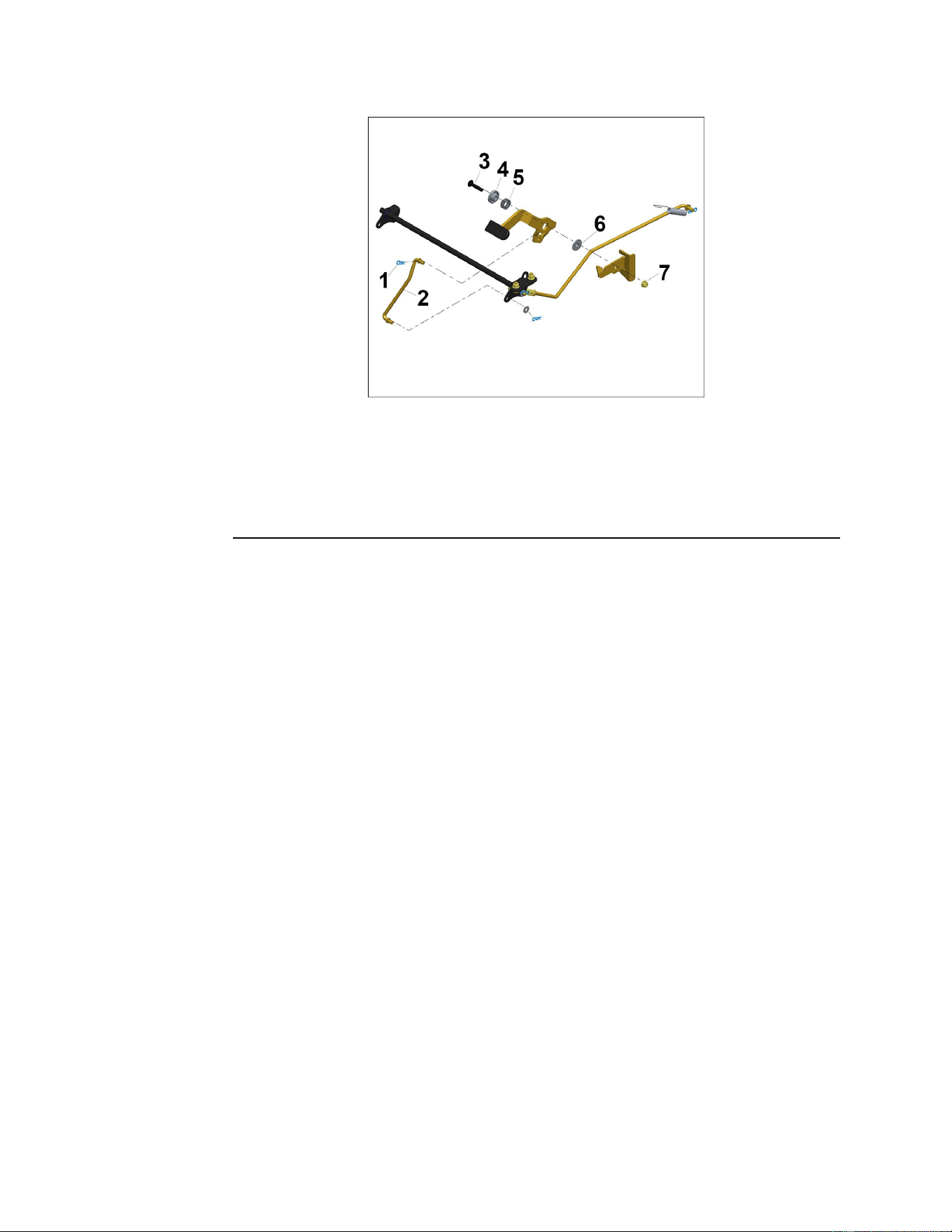
g321540
Figure49
1.CotterPin5.WaveSpring
2.IntermediateBrakeRod6.BrakeFlangedBushing
3.T orxScrew
7.FlangeNut
4.FlangeBushing
1.ParkthemachineonalevelsurfaceanddisengagethePTO.Stopthe
engine,waitforallmovingpartstostop,andremovekey.
2.Disconnectthebatterybyremovingthenegativecablerst,thenthepositive
cablefromthebattery.
3.Removetheleftsideconsole.
4.Re-installthefuelcap.
5.Removethelockingcotterpinsecuringtheintermediatebrakerodtothe
parkbrakelever.
6.Removetheboltandangenutfromtheparkbrakeleverassembly.Retain
thebushingandwavespring.
ParkBrakeHandleAssemblyInstallation
1.Assemblethebushingsandwavespringovertheboltandthroughthepark
brake.
Note:Assemblethebushingsandwavespringovertheboltandthrough
theparkbrake
Chassis:ServiceandRepairs
Page5–24
TitanServiceManual
3438-774RevA
ParkBrakeHandleAssemblyInstallation(continued)
g321541
Figure50
1.Screw
4.Washer
2.WaveWasher5.FlangePivot
3.FlangeNut
2.Withtheparkbrakehandlehardwareorientedasshown,installthebolt
throughthebrakedetentandconnecttheangenut.Torqueto23±3N•m
(200±25in-lb).
g321540
Figure51
1.CotterPin
5.WaveSpring
2.IntermediateBrakeRod6.BrakeFlangedBushing
3.T orxScrew
7.FlangeNut
4.FlangeBushing
3.Installtheintermediatebrakerodandsecurewithlockingcotterpin.
4.Cycletheparkbrakelevertoensurethatitlocksintheengagedposition.
5.Connectthebatterybyinstallingthepositivecablerst,thenthenegative
cabletothebattery.
TitanServiceManual
Page5–25
Chassis:ServiceandRepairs
3438-774RevA
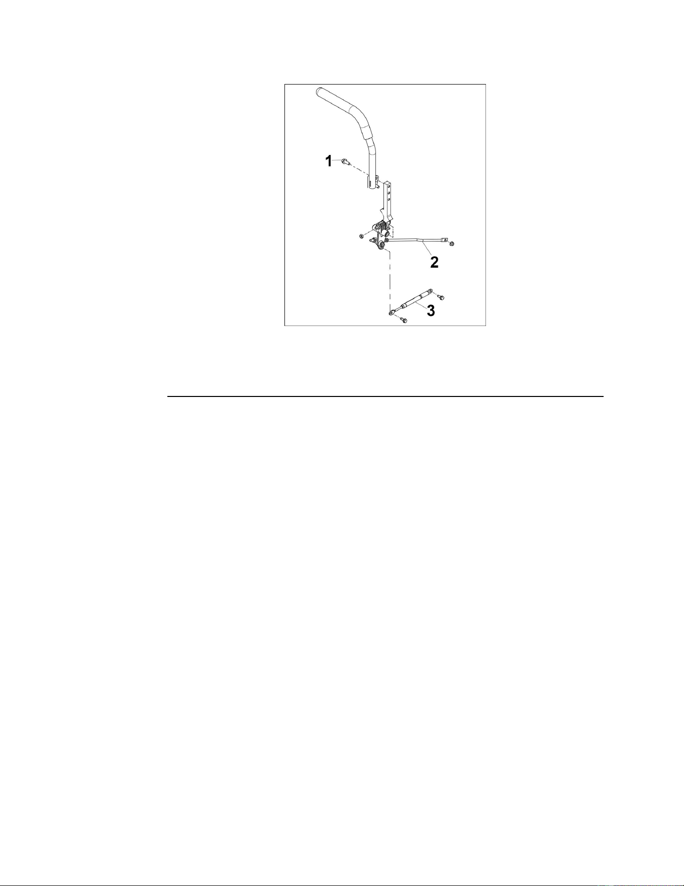
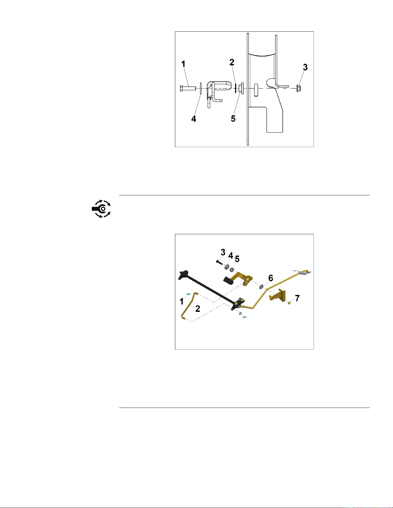
MotionControlAssemblyReplacement
MotionControlAssemblyRemoval
g321537
Figure52
1.Bolt
3.MotionControlDamper
2.MotionControlLinkage
1.ParkthemachineonalevelsurfaceanddisengagethePTO.Stopthe
engine,waitforallmovingpartstostop,andremovekey.
2.Disconnectthebatterybyremovingthenegativecablerst,thenthepositive
cablefromthebattery.
3.Raiseandsupporttheunitsothatthedrivewheelsareofftheground.
Note:Theconsolemustberemovedforaccess.
4.Removethe2boltssecuringthemotioncontrolhandletothemotioncontrol
assembly.
5.Disconnectthemotioncontroldamperfromthemotioncontrolassembly.
6.Disconnectthemotioncontrollinkagefromthemotioncontrolassembly.
7.Disconnectthemotioncontrolassemblyfromtheframe.
Chassis:ServiceandRepairs
Page5–26
TitanServiceManual
3438-774RevA
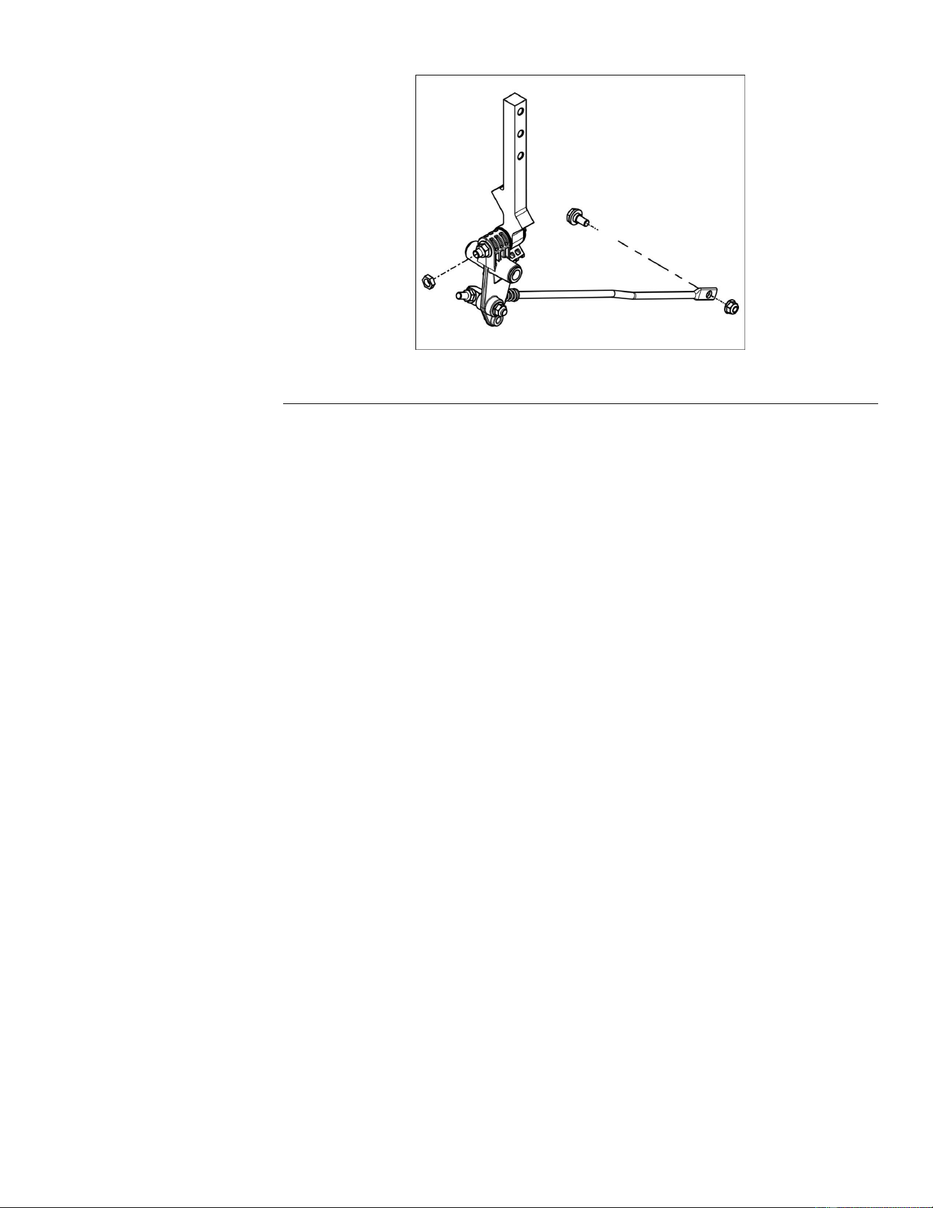
MotionControlAssemblyRemoval(continued)
g321539
Figure53
MotionControlAssemblyInstallation
1.Positionthemotioncontrolassemblyinplacewiththelinkageextending
towardthetransmission.
2.Securethemotioncontrolassemblytotheframe.
3.Connectthemotioncontrollinkagetothemotioncontrolassembly.
4.Connectthemotioncontroldampertothemotioncontrolassembly.
5.Connectthemotioncontrolhandletothemotioncontrolassemblyusing
thetwobolts.
6.Adjusttheneutralsetting.NeutralAdjustment(page6–4)
7.Connectthebatterybyinstallingthepositivecablerst,thenthenegative
cabletothebattery.
8.Lowertheunitandverifyproperfunction.
9.Adjustthetrackingifnecessary.TrackingAdjustment(page6–5)
AdjusttheMotionControlHandle
Note:Ensureproperadjustmentofneutralandtrackingsettingsbeforeadjusting
themotioncontrolhandles.
1.ParkthemachineonalevelsurfaceanddisengagethePTO.Stopthe
engine,waitforallmovingpartstostop,andremovekey.
2.Disconnectthebatterybyremovingthenegativecablerst,thenthepositive
cablefromthebattery.
3.Movetheleversintotheoperatingposition.
4.Loosenthe2boltsthatsecurethemotioncontrolhandlestothemotion
controlassembly.
5.Aligntheleversfronttobackandsecurethebolts.
TitanServiceManual
Page5–27
Chassis:ServiceandRepairs
3438-774RevA
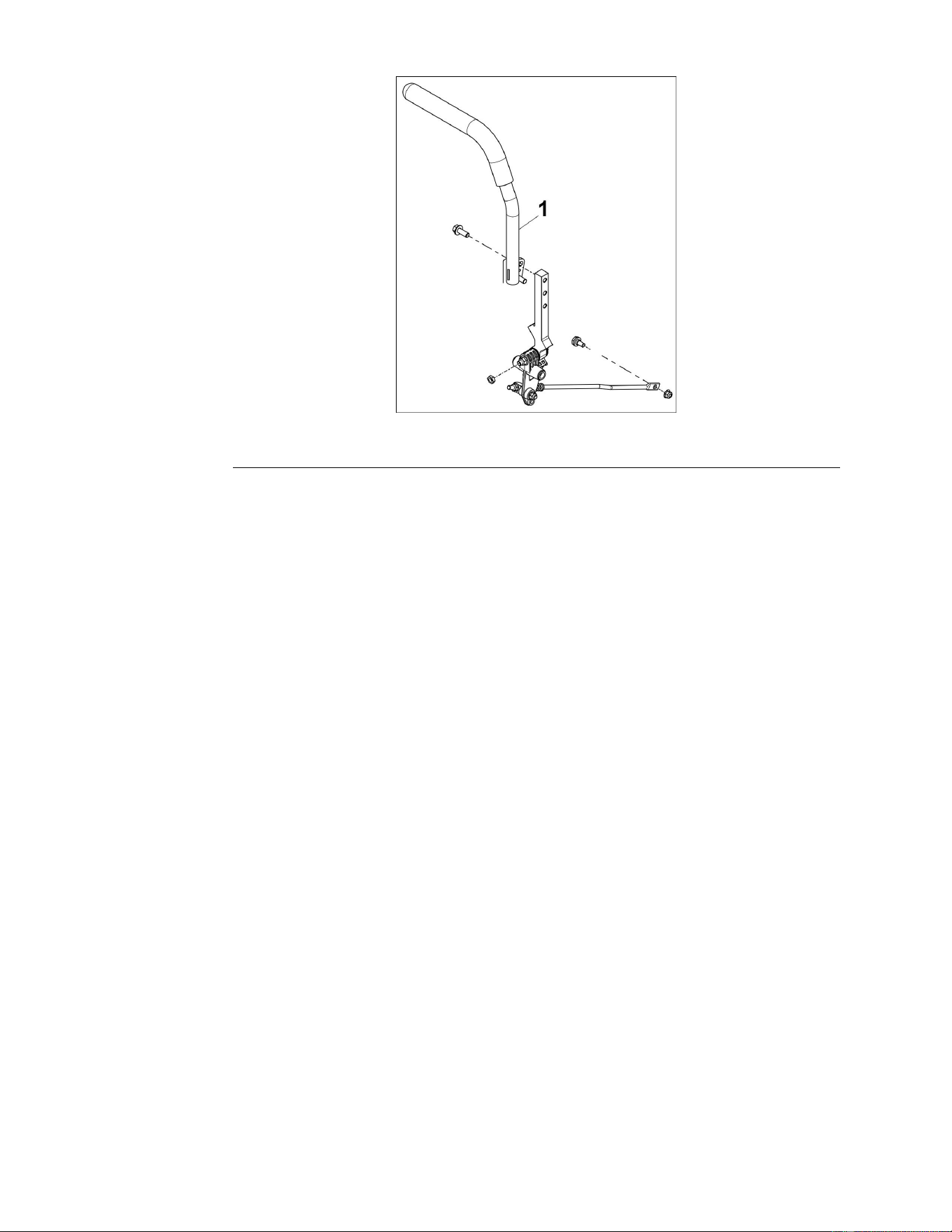
AdjusttheMotionControlHandle(continued)
g321538
Figure54
6.Movetheleversintotheparkposition.
7.Connectthebatterybyinstallingthepositivecablerst,thenthenegative
cabletothebattery.
8.Verifyproperfunctionoftheunit.
Note:Motioncontrolleversmaybeadjustedupordownaswellforoperator
comfortbyutilizingtheadditionalmountingholesonthemotioncontrol
assembly.Themotioncontrolleversshouldalwaysbemountedontheinside
ofthemotioncontrolassembly.
Chassis:ServiceandRepairs
Page5–28
TitanServiceManual
3438-774RevA

Chapter6
HydrostaticDriveSystem
TableofContents
GeneralInformation..............................................................................................................................6–2
ServiceandRepairs.............................................................................................................................6–3
UsingtheDriveWheelReleaseValves(BypassValves)....................................................................6–4
NeutralAdjustment............................................................................................................................6–4
TrackingAdjustment..........................................................................................................................6–5
HydroChangeProcedure..................................................................................................................6–5
PurgingProcedure.............................................................................................................................6–6
HydrostaticDriveBeltReplacement...................................................................................................6–7
HydrostaticDriveTransmissionReplacement....................................................................................6–9
TitanServiceManual
Page6–1
HydrostaticDriveSystem
3438-774RevA

GeneralInformation
TheTITAN®seriesofmowersuseHydro-Gearhydrostatictransaxlesmodel
ZT-2800.Alldrivesusethesametypeofuid.Theoilmusthaveaminimum
ratingof9.0cSt(55SUS)at230°F(110°C)withanAPIclassicationofSLis
recommended.A20W-50engineoilhasbeenselectedforusebythefactory
andisrecommendedfornormaloperatingprocedures.
HydrostaticDriveSystem:GeneralInformation
Page6–2
TitanServiceManual
3438-774RevA

UsingtheDriveWheelReleaseValves(BypassValves)
Thedrivewheelreleasevalvesarelocatedontheleftandrightsidesunderneath
theengineblock.
1.ParkthemachineonalevelsurfaceanddisengagethePTO.Stopthe
engine,waitforallmovingpartstostopandremovethekey.Engagethe
parkingbrake.
2.Disconnectthebatterybyremovingthenegativecablerst,thenthepositive
cablefromthebattery.
3.Locatethebypassleversontheframeonbothsidesoftheengine.
4.Movethebypassleverforwardthroughthekeyholeanddowntolockthem
inplace.Dothisforeachbypasslever.
5.Disengagetheparkingbrakebeforepushingthemachine.Donotstartthe
machine.
6.Tooperatethemachinenormally,movethebypassleverstotherearward
positionthroughthekeyhole.
7.Connectthebatterybyinstallingthepositivecablerst,thenthenegative
cabletothebattery.
NeutralAdjustment
1.ParkthemachineonalevelsurfaceanddisengagethePTO.Stopthe
engine,waitforallmovingpartstostop,andremovethekey.Engagethe
parkingbrake.
2.Raiseandsupporttheunitsothatthedrivewheelsareofftheground.
3.Unplugtheseatswitchonthebottomsideoftheseatandinstallatemporary
jumperwireacrosstheplugconnector(wireharnessside).
4.Starttheengineandallowthemachinetowarm-upfor3–5minutes.
5.Disengagetheparkingbrake.
6.Movethemotioncontrolleversintotheneutralposition.
7.Increasetheenginespeedtofullthrottle.Observethemovementoftherear
drivewheels.Ifeitherdrivewheelismovinginforwardorreverse,aneutral
adjustmentisneeded.
Note:Aslightcreepinreverseisacceptable.
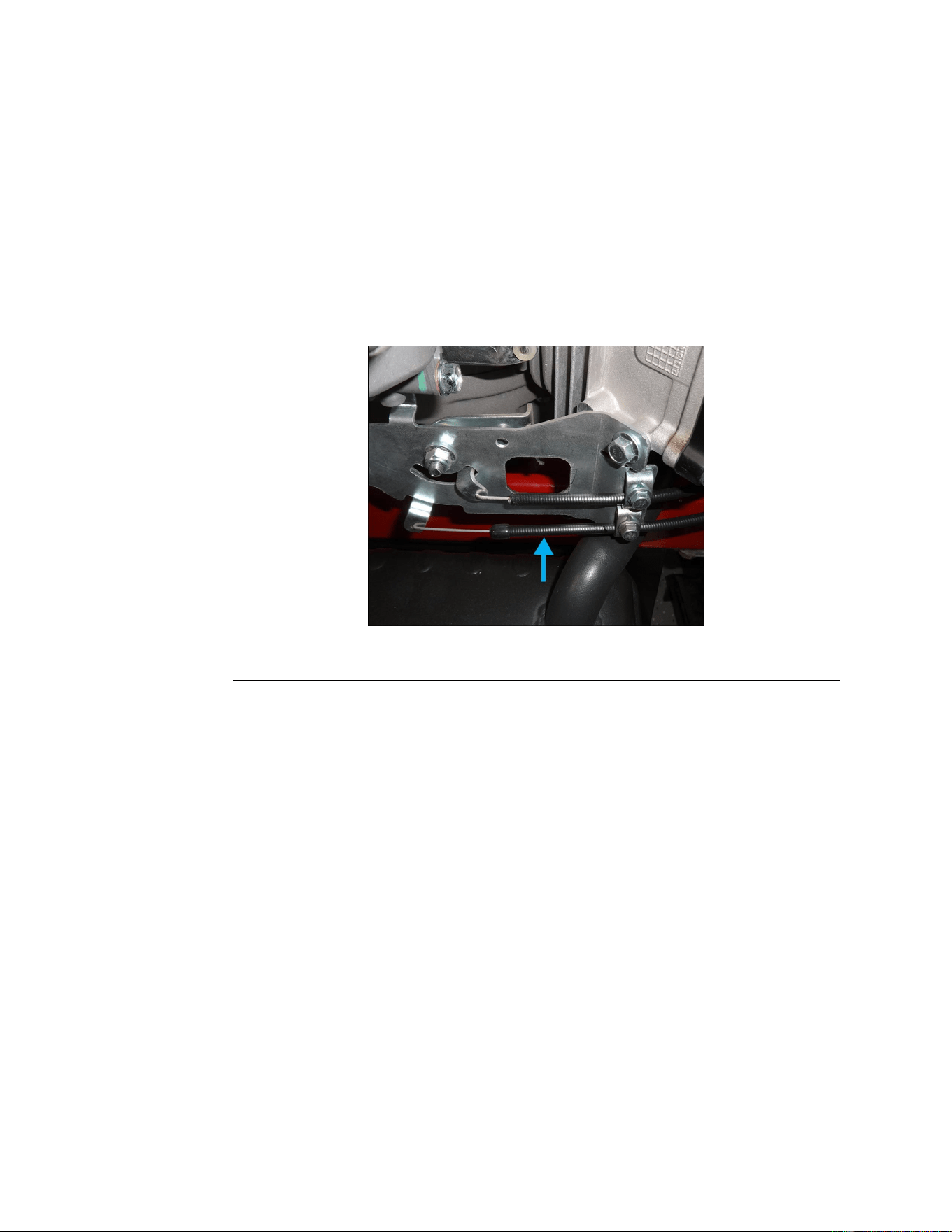
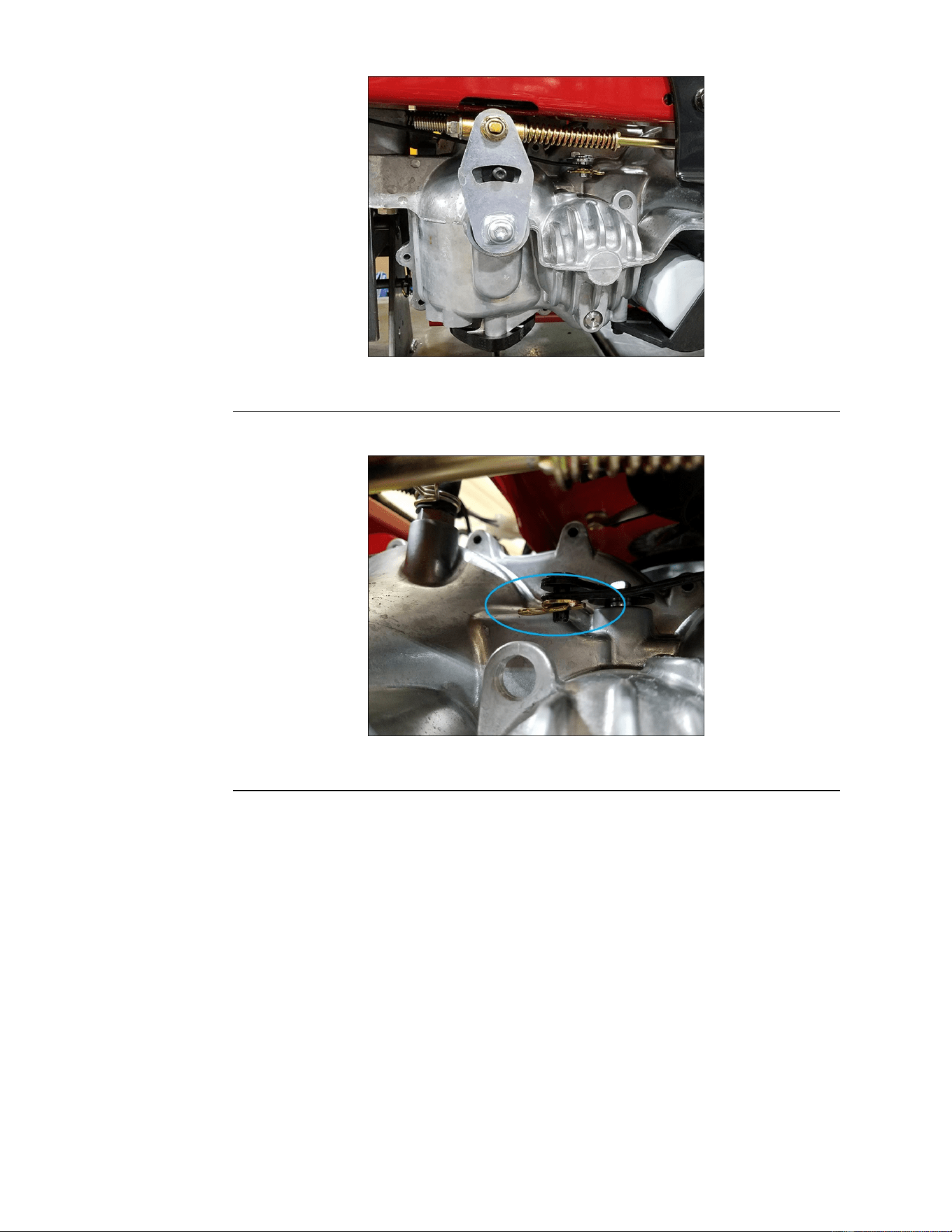
8.Turntheadjustmentnutonthemotioncontrolrodclockwiseor
counterclockwiseuntilthedrivewheelisslightlyrotatinginreverseornot
rotatingatall.Repeatforbothdrivewheelsifnecessary.
Note:Whentheunitisinneutral,thestudshouldberoughlycenteredin
theslotofthecontrolplate.
HydrostaticDriveSystem:ServiceandRepairs
Page6–4
TitanServiceManual
3438-774RevA
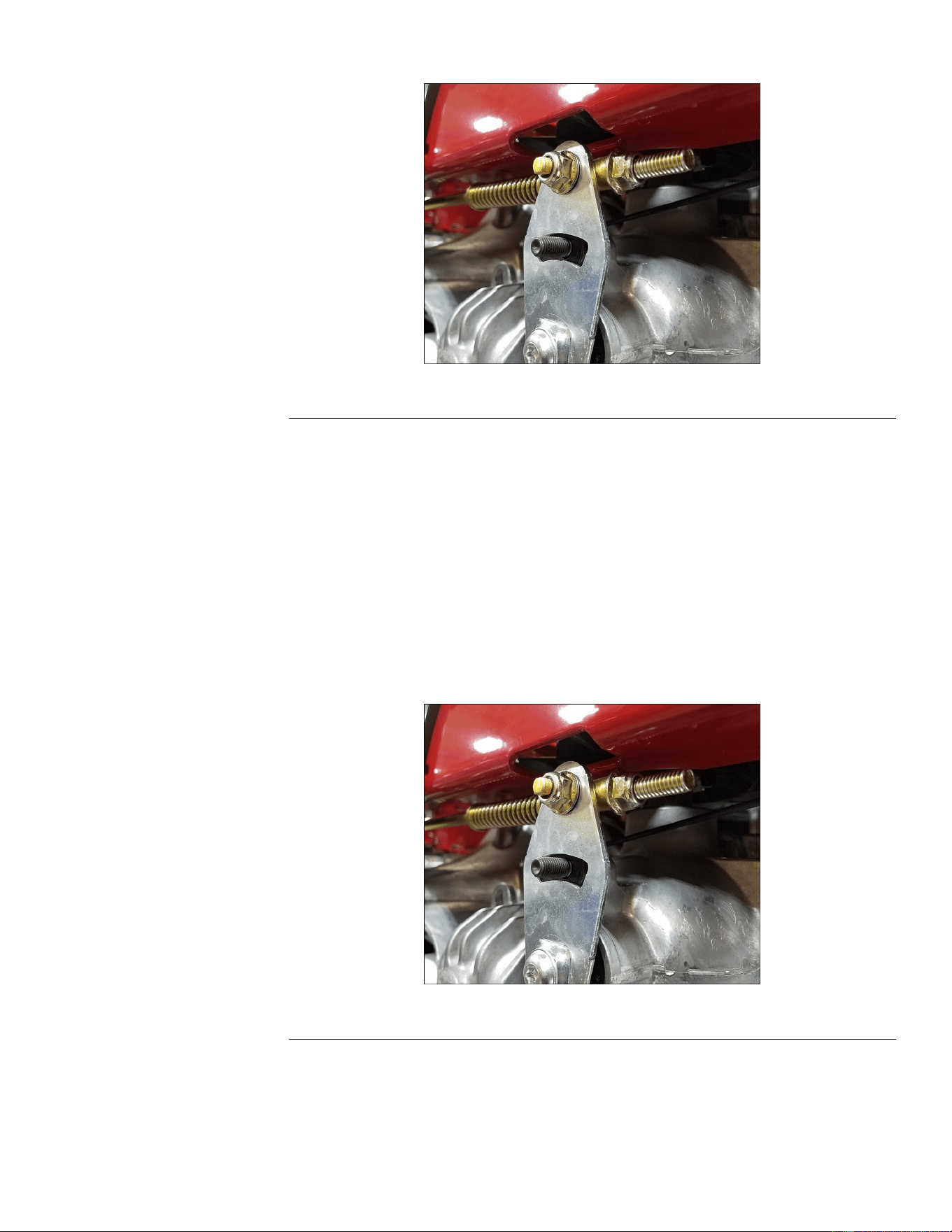
NeutralAdjustment(continued)
g321828
Figure56
9.Stoptheengineandlowertheunit.
10.Verifyproperneutralsettingandtracking.
TrackingAdjustment
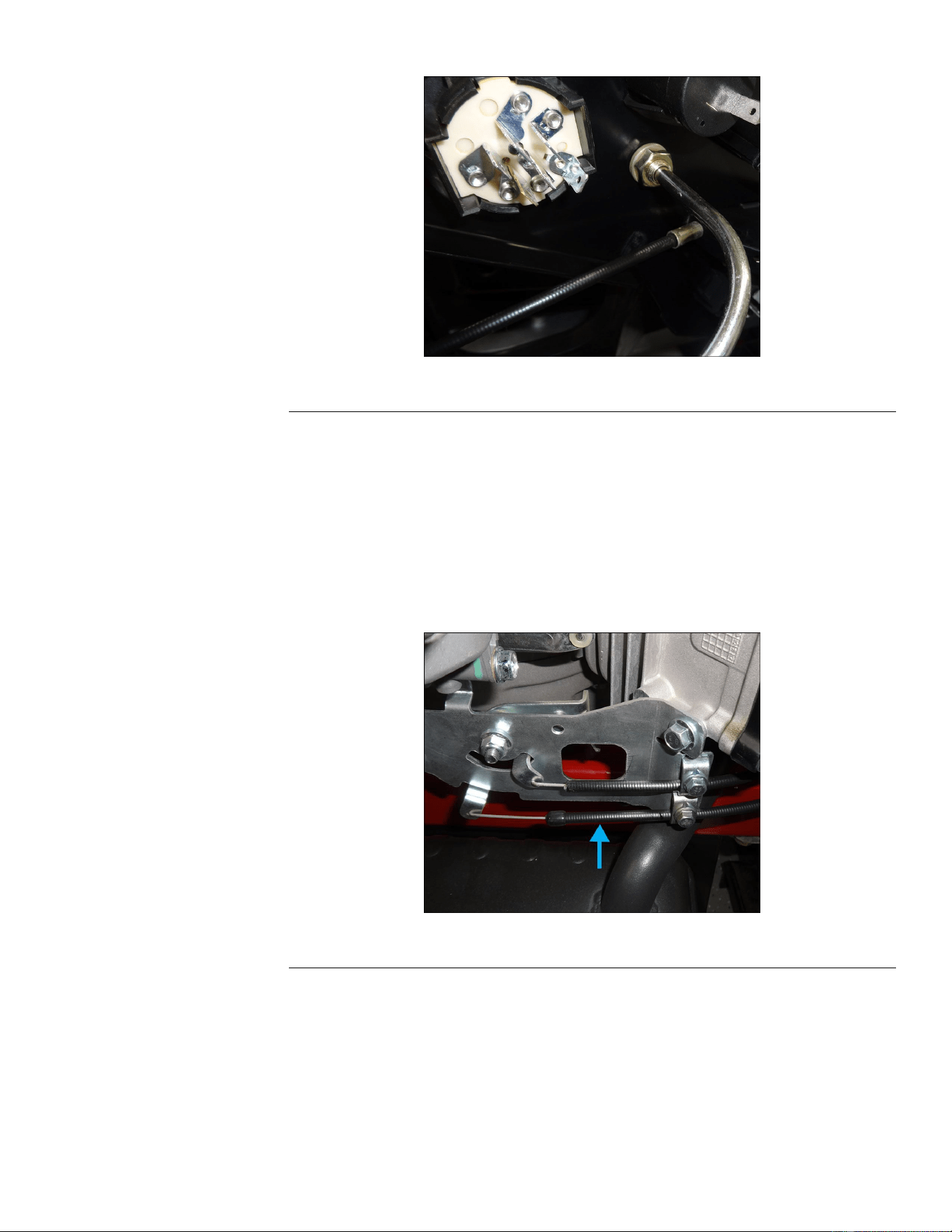
IftheunittracksorpullstotheRIGHT
TurntheLHadjustmentnut1fullturnclockwise.Ifmoreadjustmentisneeded,
turntheadjustmentnut1fullturnatatime.
IftheunittracksorpullstotheLEFT
TurntheRHadjustmentnut1fullturnclockwise.Ifmoreadjustmentisneeded,
turntheadjustmentnut1fullturnatatime.
g321828
Figure57
HydroChangeProcedure
1.ParkthemachineonalevelsurfaceanddisengagethePTO.Stoptheengine,
waitforallmovingpartstostop,andremovekey.Engagetheparkingbrake
TitanServiceManual
Page6–5
HydrostaticDriveSystem:ServiceandRepairs
3438-774RevA
HydroChangeProcedure(continued)
2.Disconnectthebatterybyremovingthenegativecablerst,thenthepositive
cablefromthebattery.
3.Removethespinonoillter.
4.Drainthehydraulicoil.
5.Installanewspinonoillter.
6.Removethetopportplugfromthehydro.
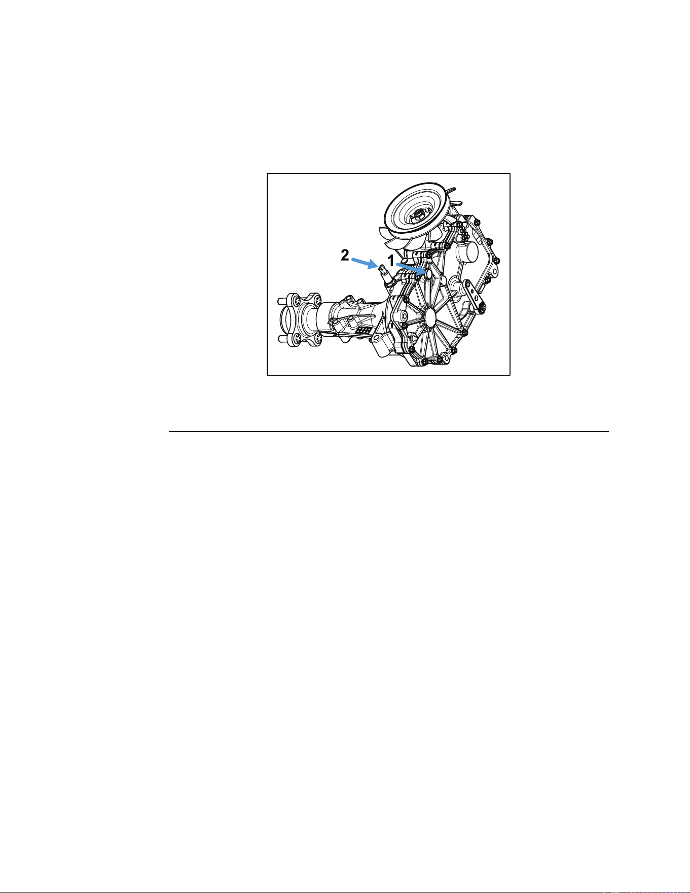
g334863
Figure58
1.T opPortPlug2.BreatherHole
7.Removethebreatherhoseandllventlocatedonthetopofthehydro.
8.Fillapproximately2quartsofToroHYPR-OIL®or20W-50engineoiltothe
levelofthetopportplughole.
9.Re-installthetopportplug.Figure58
10.Re-installthebreatherhose.
11.Connectthebatterybyinstallingthepositivecablerst,thenthenegative
cabletothebattery.
12.Performthepurgingprocedure.PurgingProcedure(page6–6)
PurgingProcedure
Duetotheeffectsairhasonefciencyinhydrostaticdriveapplications,it
iscriticalthatitbepurgedfromthesystem.Thispurgeprocedureshould
beimplementedanytimeahydrostaticsystemhasbeenopenedtofacilitate
maintenance,anyadditionaloilhasbeenaddedtothesystem,orareplacement
transaxlehasbeeninstalled.Aircreatesinefciencybecauseitscompression
andexpansionrateishigherthanthatoftheoilinhydrostaticdivesystems.
Theresultingsymptomsinhydrostaticsystemsmaybe:
•Noisyoperation
•Lackofpowerordriveafterashortperiodofoperation
•Highoperatingtemperatureandexcessiveexpansionofoil,oillevelmaybe
highintheexpansiontankoroverow
Thefollowingprocedureshouldbeperformedwiththevehiclewheelsoffthe
groundandthenrepeatedunderoperatingconditions.
HydrostaticDriveSystem:ServiceandRepairs
Page6–6
TitanServiceManual
3438-774RevA
PurgingProcedure(continued)
1.Withthebypassvalveopen(pushbutton)andtheenginerunning,slowly
movethedirectionalcontrols(forward/reverselevers)inbothforwardand
reversedirections5–6time;asairispurgedfromthetransaxles,theoillevel
willdrop.
Note:Seatswitchmustbebypassed.
2.Withthebypassvalvesintheclosedposition(runposition)andtheengine
running,slowlymovethedirectionalcontrolleversinbothforwardand
reversedirections5–6times.
3.Itmaybenecessarytorepeatsteps1and2untilairiscompletelypurged
fromthetransaxles.Whenthetransaxlesmoveforwardatnormalspeed,
purgingiscomplete.
HydrostaticDriveBeltReplacement
HydrostaticDriveBeltRemoval
1.ParkthemachineonalevelsurfaceanddisengagethePTO.Stoptheengine,
waitforallmovingpartstostop,andremovekey.Engagetheparkingbrake.
2.Disconnectthebatterybyremovingthenegativecablerst,thenthepositive
cablefromthebattery.
3.Raiseandsupporttheunitsothatthedrivewheelsareofftheground.
4.Removethemowerbeltfromtheclutch.
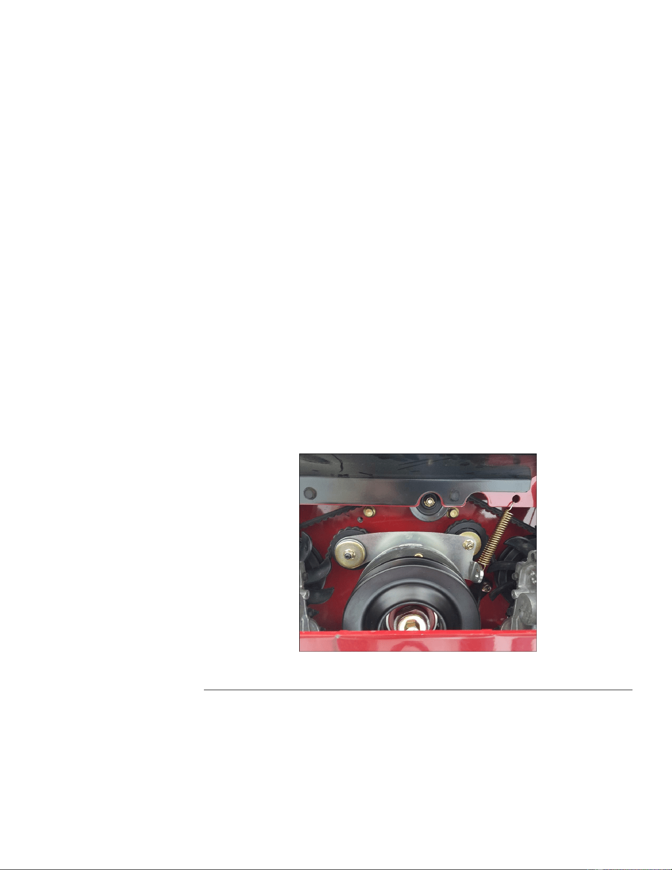
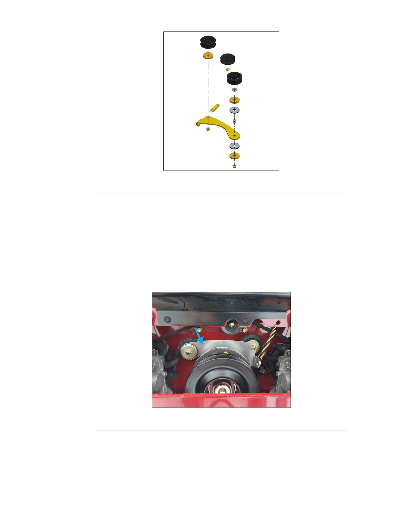
5.Usingaspringremovaltool,removethedriveidlerspringfromtheslotinthe
frame.Removethespringfromthedriveidlerarmandinspectfordamage
orwear
g321832
Figure59
6.Removetheclutchstop.
7.Removetherearpulley.
8.Removetheidlerarmandpulley.
TitanServiceManual
Page6–7
HydrostaticDriveSystem:ServiceandRepairs
3438-774RevA
HydrostaticDriveBeltRemoval(continued)
g321838
Figure60
9.Removethedrivebeltfromthehydrostaticdrivepulleys.
Note:Inspectthebeltforexcessivewear,damage,orcracking,replace
ifnecessary.
HydrostaticDriveBeltInstallation
1.Routethehydrostaticdrivebeltaroundthetwotransmissionpulleys.
2.Routethedrivebeltaroundtheenginepulley.
3.Installtheidlerarmandpulleys.
Note:Makesurethatthebeltisproperlyroutedbeforeinstallation.
g321833
Figure61
4.Installtheclutchstop.
5.Verifyproperroutingofthebelt.
6.Placetheidlerspringontotheidlerarmloopanduseaspringremovaltoolto
securethespring(A)intotheslotontherightrearoftheframe.
HydrostaticDriveSystem:ServiceandRepairs
Page6–8
TitanServiceManual
3438-774RevA
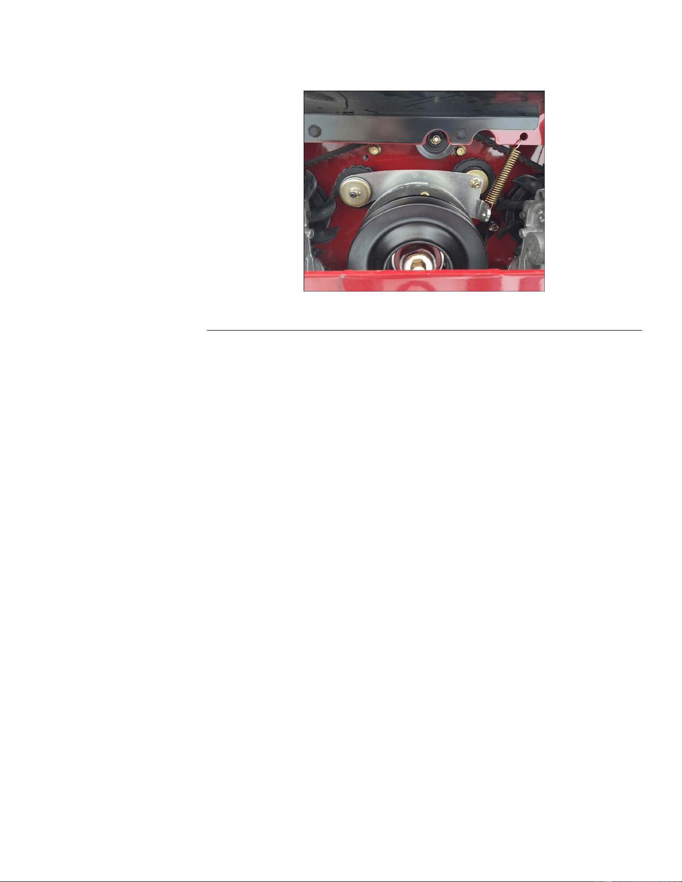
HydrostaticDriveBeltInstallation(continued)
Note:Ensureproperorientationwithhookopeningsfacingawayfromthe
idlerpivot.
g321832
Figure62
7.Installthemowerbeltontotheclutch.
8.Lowertheunit.
9.Connectthebatterybyinstallingthepositivecablerst,thenthenegative
cabletothebattery.
HydrostaticDriveTransmissionReplacement
HydrostaticDriveTransmissionRemoval
Note:Thesestepsareshownreplacingtherightsidehydrostaticdrive
transmission.Allofthesamestepsapplytotheleftsidehydrostaticdrive
transmission.
1.Stoptheengine,waitforallmovingpartstostop,andremovekey.Engage
theparkingbrake.
2.Disconnectthebatterybyremovingthenegativecablerst,thenthepositive
cablefromthebattery.
3.Raiseandsupporttheunitsothatthedrivewheelsareofftheground.
4.Removethedrivewheel(s).
5.Removethedrivebelt.
6.Disconnectthemotioncontrollinkagefromthetransmission.
TitanServiceManual
Page6–9
HydrostaticDriveSystem:ServiceandRepairs
3438-774RevA
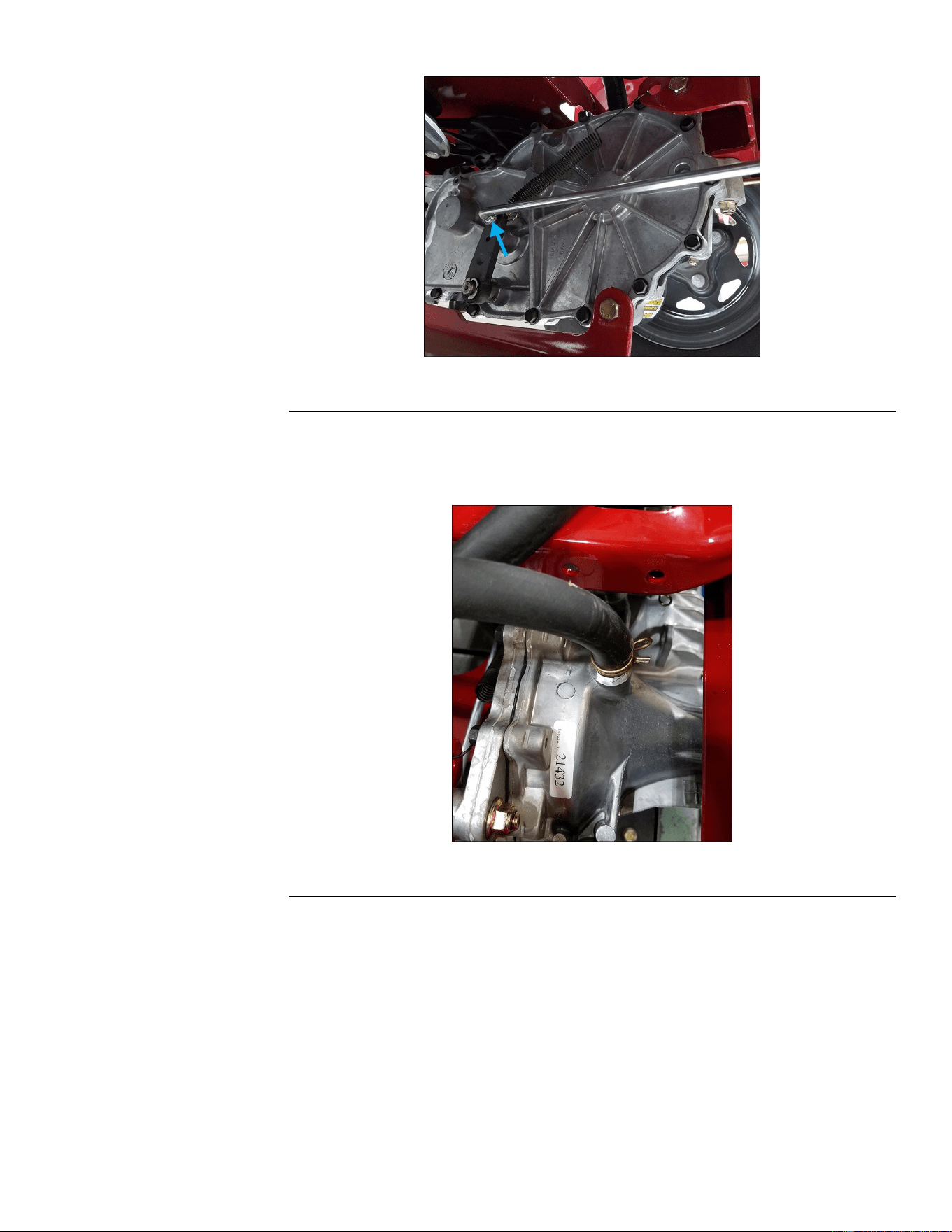
HydrostaticDriveTransmissionRemoval(continued)
g321834
Figure65
9.Disconnecttheconnectorssecuringtheoverowtubetothechassis.
Note:Overowtubesshouldstayconnectedtothetopofthetransmission.
Toavoidoilleaking,keeptheoverowtubesorientedup.
g321831
Figure66
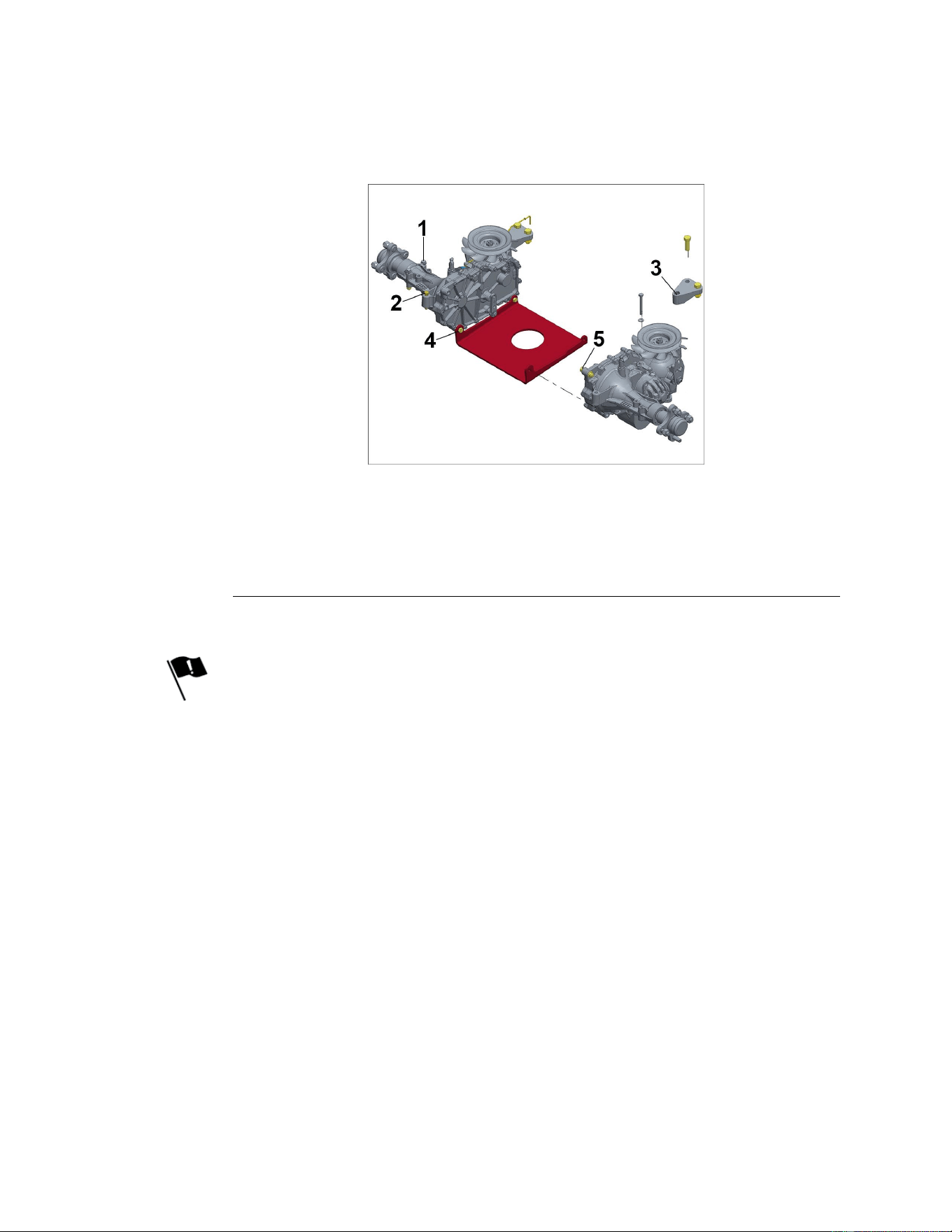
10.Removethe4bolts(2boltsperside)securingthetransmissiontothehydro
crossplate.
11.Loosenthe4outerframemountingbolts(2boltsperside).
12.Loosenthe2boltsconnectingthetransmissiontotherearcrossmember.
13.Removethefrontmountingbolt.
14.Supportthetransmissionandremovethemountinghardware.Lowerthe
transmission.
TitanServiceManual
Page6–11
HydrostaticDriveSystem:ServiceandRepairs
3438-774RevA
HydrostaticDriveTransmissionInstallation
Note:Thesestepsareshownreplacingtherightsidehydrostaticdrive
transmission.Allofthesamestepsapplytotheleftsidehydrostaticdrive
transmission.
1.Liftandsupportthetransmission,andinstallthe2outerframemountingbolts
andnutsasshown.Donotfullytightenatthistime.
g321836
Figure67
1.Outermountingboltstoframebracket
4.Bottommountingboltstocrossplate
2.Frontmid-mountingboltstoframebracket5.Frontinnermountingboltstoframebracket
3.Rearmid-mountingboltstocrossmember
rear
2.Alignthehydrocrossplateandinstallthe4bolts(2boltsperside)through
thecrossplateandthetransmission.Donottightenatthistime.
3.Installtherearandfronthydromounting4boltsandnutsperside(3inthe
rear,1inthefront).Donottightenatthistime.
Note:Thepropertorquesequence,asoutlinedbelow,iscriticalinavoiding
damagetothehydrostatictransmissionsandtheframe.
•Tightenthefrontmountingboltthroughtheframebracket.
•Tightenthehydrocrossplatebolts.
•Tightentherearhydromountingbolts.
•Tightenthe2outermountingbolts.
4.Removetheprotectivecapfromthehydraulicoilnipple,installtheoverow
tube,andmovethehoseclampsintoplace.
HydrostaticDriveSystem:ServiceandRepairs
Page6–12
TitanServiceManual
3438-774RevA
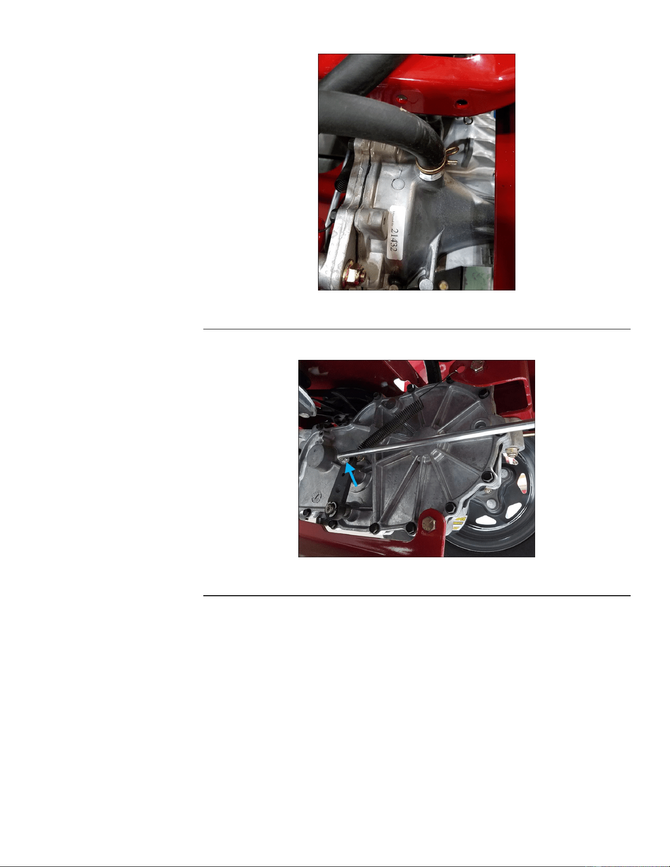
HydrostaticDriveTransmissionInstallation(continued)
g321835
Figure70
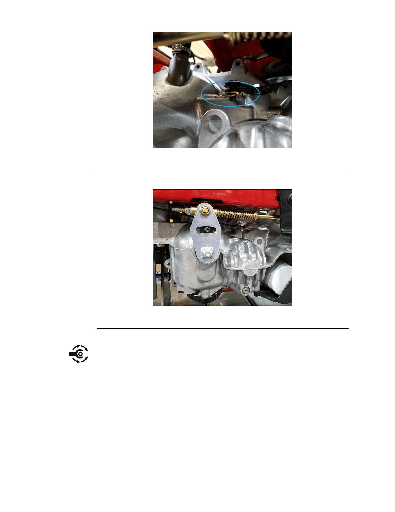
7.Connectthemotioncontrollinkage.
g321830
Figure71
8.Installthedrivebelt.
9.Installthedrivewheelandtorquethelugnutsto110±14N•m(80±10ft-lbs).
10.Addhydraulicoiltotheproperlevelusingtheventplugs.
HydrostaticDriveSystem:ServiceandRepairs
Page6–14
TitanServiceManual
3438-774RevA
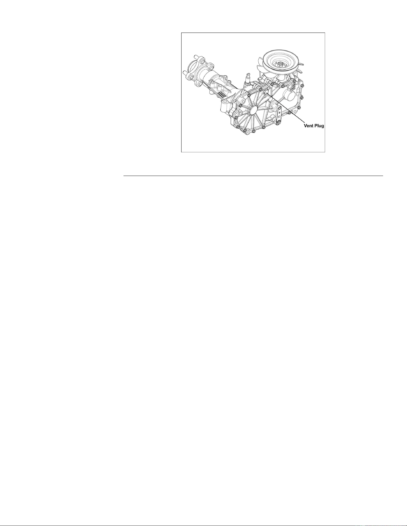
HydrostaticDriveTransmissionInstallation(continued)
g321839
Figure72
11.Followthepurgingproceduretoremoveallairfromthesystem.
12.Adjusttheneutralsetting,ifnecessary.
13.Lowertheunitandverifyproperfunction.
14.Connectthebatterybyinstallingthepositivecablerst,thenthenegative
cabletothebattery.
TitanServiceManual
Page6–15
HydrostaticDriveSystem:ServiceandRepairs
3438-774RevA


Chapter7
MowerDeck
TableofContents
GeneralInformation..............................................................................................................................7–2
ServiceandRepairs.............................................................................................................................7–3
MowerBeltReplacement...................................................................................................................7–6
MowerDeckReplacement.................................................................................................................7–7
MowerSpindle...................................................................................................................................7–8
ElectricPTOClutchReplacement....................................................................................................7–11
TitanServiceManual
Page7–1
MowerDeck
3438-774RevA

ServiceandRepairs
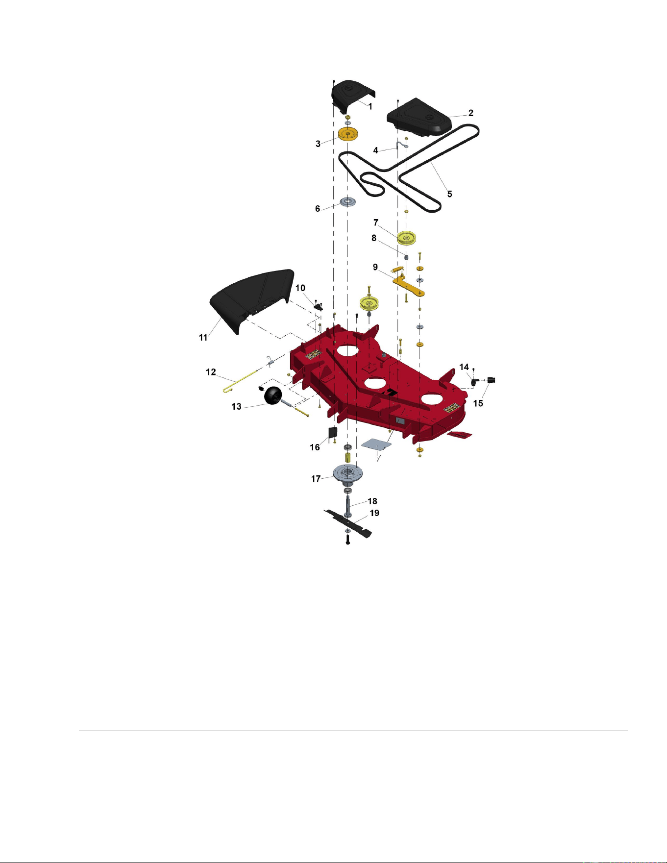
MowerDeckAssembly1
g334873
Figure73
1.RHBeltCover11.DischargeDeector
2.LHBeltCover12.ChutePin
3.Pulley
13.AntiScalpRoller
4.IdlerBeltGuide
14.WashoutFitting
5.V-Belt
15.HoseConnector
6.BearingShield16.CutoffBafe
7.FlatIdlerPulley
17.SpindleAsm
8.IdlerBushing
18.SpindleShaft
9.IdlerArmAsm19.Blade
10.WashoutFitting
TitanServiceManual
Page7–3
MowerDeck:ServiceandRepairs
3438-774RevA
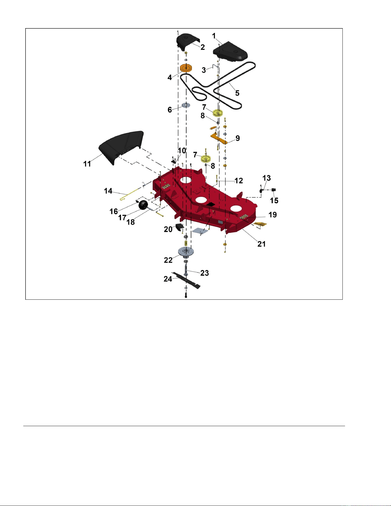
MowerDeckAssembly2
g322345
Figure74
1.LeftBeltCover13.WashoutSpacer
2.RightBeltCover14.ChutePin
3.IdlerBeltGuide15.ConnectorHose
4.Pulley
16.RearAxleSpacer
5.V-Belt
17.Anti-ScalpRoller
6.BearingShield18.SpannerTube
7.FlatIdlerPulley19.DeckAsm
8.IdlerBushing
20.Cut-offBafe
9.IdlerArmAsm21.DeckAsm
10.WashoutFitting
22.SpindleAsm
11.DischargeDeector23.SpindleShaft
12.SpacerFender
24.MulchBlade
MowerDeck:ServiceandRepairs
Page7–4
TitanServiceManual
3438-774RevA
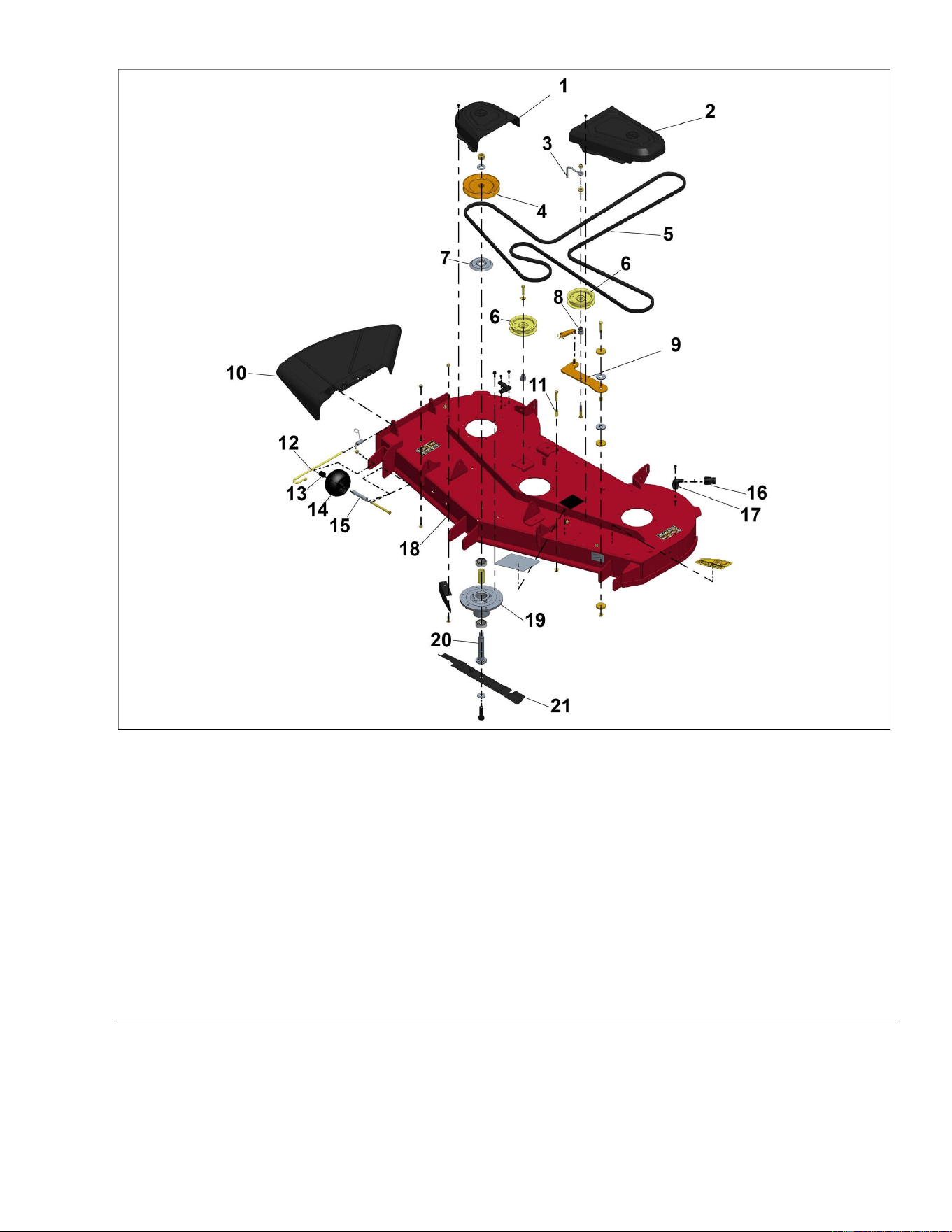
MowerDeckAssembly3
g322346
Figure75
1.RightBeltCover12.ChutePin
2.LeftBeltCover13.RearAxleSpacer
3.IdlerBeltGuide14.Anti-ScalpRoller
4.Pulley
15.SpannerTube
5.V-Belt16.WashoutFitting
6.FlatIdlerPulley
17.ConnectorHose
7.BearingShield
18.DeckAsm
8.IdlerBushing
19.SpindleAsm
9.IdlerArmAsm
20.SpindleShaft
10.DischargeDeector
21.MulchBlade
11.SpacerFender
TitanServiceManual
Page7–5
MowerDeck:ServiceandRepairs
3438-774RevA
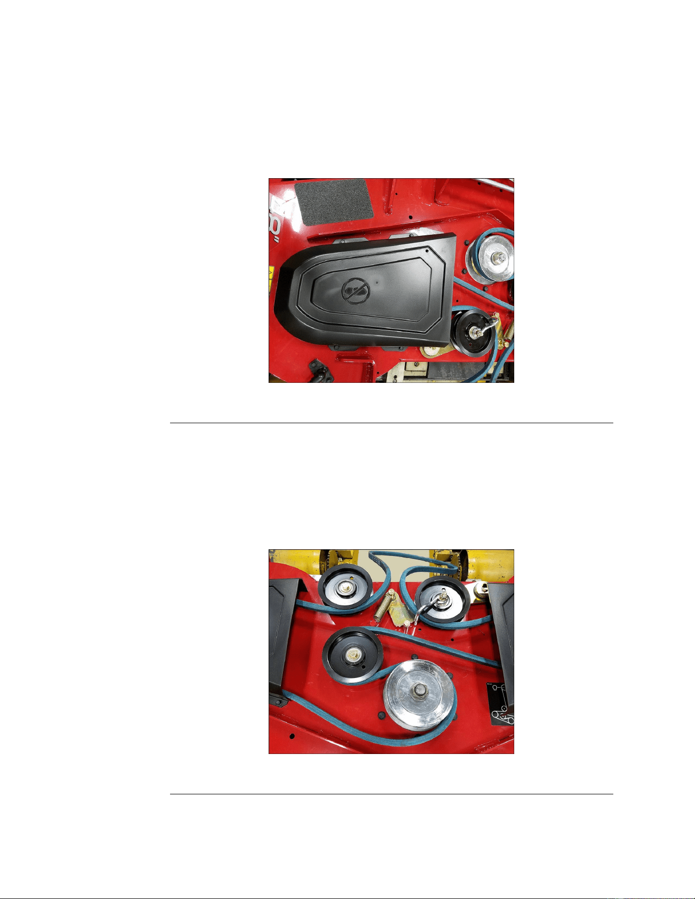
MowerBeltReplacement
MowerBeltRemoval
1.ParkthemachineonalevelsurfaceanddisengagethePTO.Stoptheengine,
waitforallmovingpartstostop,andremovekey.Engagetheparkingbrake
2.Disconnectthebatterybyremovingthenegativecablerst,thenthepositive
cablefromthebattery.
3.Lowerthemowerdecktothe76mm(3inches)height-of-cutposition.
4.Removetheboltsfromthecoversandliftcoversoffthedeck.
g322061
Figure76
5.Usingaspringremovaltoolremovethespringtensionfromtheidlerpulley.
6.Lowerthedecktothelowestheightofcutpositionandsecurethepinto
lockinposition.
7.Removethebeltfromthedeckpulleysandtheclutchpulley.
MowerBeltInstallation
1.Routethenewbeltaroundtheclutchpulleyanddeckpulleys.
g322062
Figure77
2.Installtheidlerspringusingthespringremovaltool.
3.Ensurethatthebeltisproperlyseatedinallpulleys.
MowerDeck:ServiceandRepairs
Page7–6
TitanServiceManual
3438-774RevA
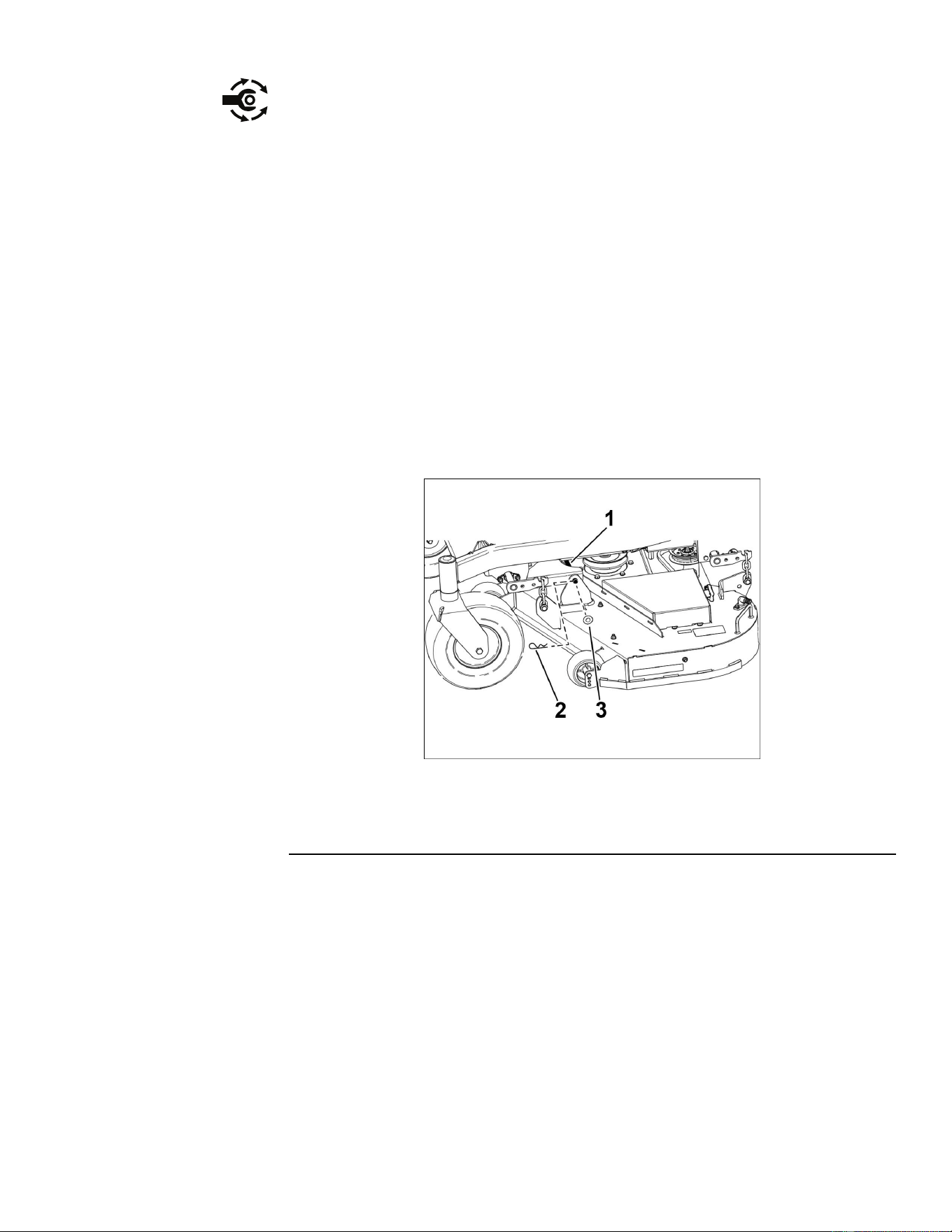
MowerBeltInstallation(continued)
4.Installthebeltcovers.Torquethebeltcoverboltsto6–8N•m(50–75in-lb).
5.Tightentheboltstosecurethecovertothedeck.
6.Connectthebatterybyinstallingthepositivecablerst,thenthenegative
cabletothebattery.
MowerDeckReplacement
MowerDeckRemoval
1.ParkthemachineonalevelsurfaceanddisengagethePTO.Stoptheengine,
waitforallmovingpartstostop,andremovekey.Engagetheparkingbrake.
2.Disconnectthebatterybyremovingthenegativecablerst,thenthepositive
cablefromthebattery.
3.Removetheheightadjustmentpinandlowerthedecktotheground.
4.Removethemowerbelt.
5.Removethe2hairpinsandwashersthatsecurethelinkpintotheframe
anddeck,thenremovethelinkpin.
g322064
Figure78
1.LinkPin3.Washer
2.HairpinCotter
6.Liftthemowerdecktoremovetensionfromthechainsandunhookthe
chainsfromthedeckliftarms.
7.Raisetheheight-of-cuttothetransportposition.
8.Slidethedeckoutfromunderneaththemachine.
MowerDeckInstallation
1.Placethedeckonthegroundandslideitintopositionunderneaththe
machine.
2.Lowertheheight-of-cutintothelowestpositionandsecurewiththe
height-of-cutpin.
3.Lifttherearofthemowerdeckandattachthechainstotherearliftarms.
4.Attachthefrontchainstothefrontdeckliftarms.
TitanServiceManual
Page7–7
MowerDeck:ServiceandRepairs
3438-774RevA

MowerDeckInstallation(continued)
5.Installthelinkpinthroughtheframehangerandthedeck.Securewith
hairpinsandwashersthatwerepreviouslyremoved.
6.Installthemowerbeltontotheenginepulleyrst,thenontothemowerdeck.
7.Installthemowerbeltcovers.T orquethebeltcoverboltsto6–8N•m(50–75
in-lbs).
8.Raisethedecktothe76mm(3inches)height-of-cutpositionandcheck
fordecklevel.
9.Connectthebatterybyinstallingthepositivecablerst,thenthenegative
cabletothebattery.
MowerSpindle
MowerSpindleRemoval
1.ParkthemachineonalevelsurfaceanddisengagethePTO.Stoptheengine,
waitforallmovingpartstostop,andremovekey.Engagetheparkingbrake.
2.Disconnectthebatterybyremovingthenegativecablerst,thenthepositive
cablefromthebattery.
3.Removethemowerbeltcovers.
4.Removethemowerbelt.
5.Removethecuttingblade.
6.Removethe6selftappingboltsthatsecurethespindletothedeck.
7.Pullthespindleassemblydownward,throughthedeck.
MowerSpindleInstallation
1.Positionthespindleagainstthedeckandalignthemountingholes.
Note:Ensuretheundersideofthedeckiscleanbeforeproceedingwith
thespindleinstallation.
2.Install6taptitescrews.
Note:Spindletaptitescrewsarethreadforming.Donotreusespindle
mountingscrews.
3.Installthebellevillewasherwiththeconcavesidefacingthecuttingblade;
installthebladebolt.Torquethebladeboltto138–152N•m(100-110ft-lb).
4.Installthemowerbelt.
5.Installthemowerbeltcovers.
6.Connectthebatterybyinstallingthepositivecablerst,thenthenegative
cabletothebattery.
MowerDeck:ServiceandRepairs
Page7–8
TitanServiceManual
3438-774RevA
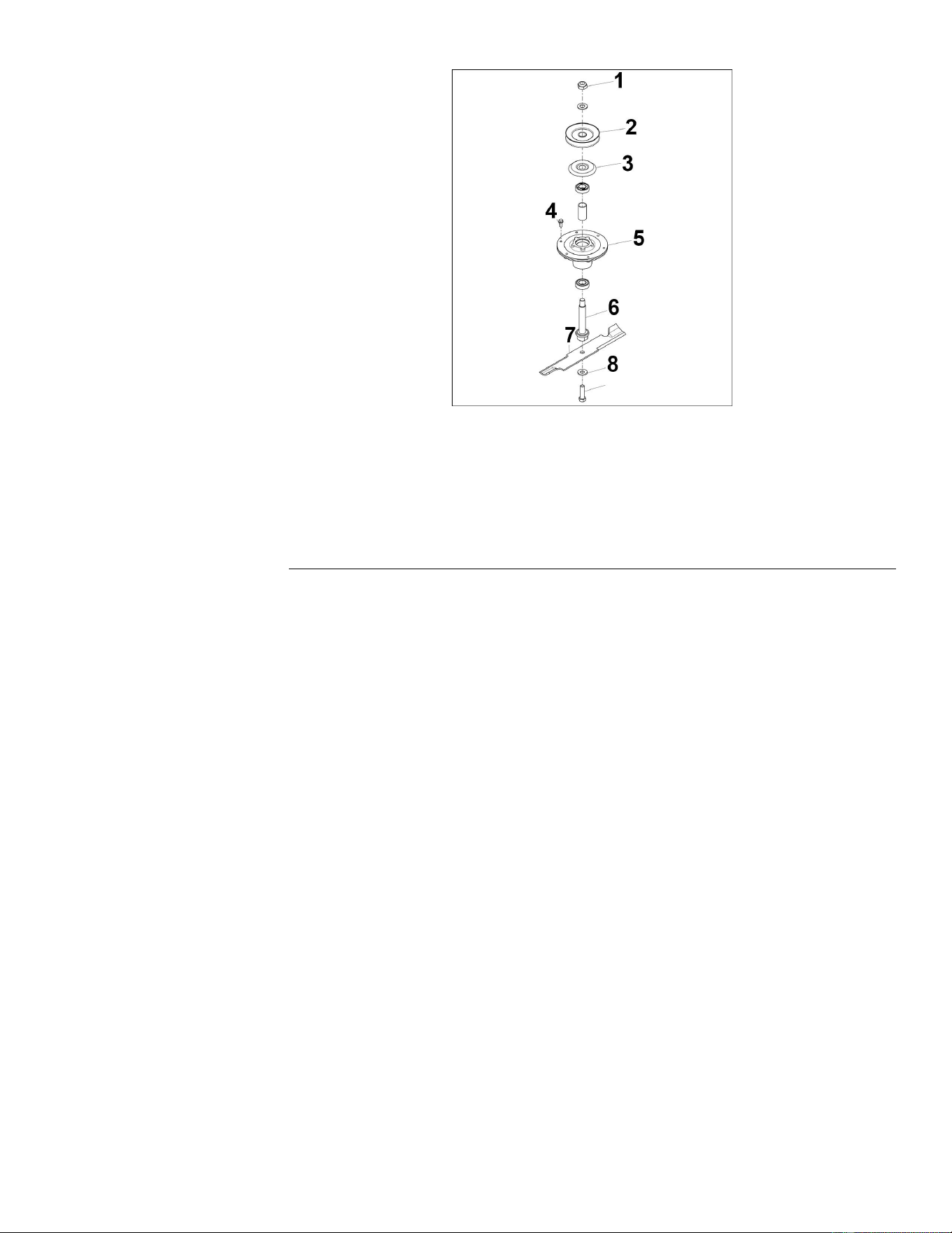
MowerSpindleDisassembly
g322066
Figure79
1.SpindleNut6.Spindle(ApplyAnti-Seize)
2.Pulley7.Blade
3.BearingShield
8.BellevilleWasher
4.SpindleMountingScrews
9.BladeBolt
5.SpindleAssembly
1.Clampthespindleforservicebyplacingthespindleshaftinavise.
2.Removethenutandwasherfromthetopofthepulley.
3.Removethepulley.
4.Removespindlehousingfromtheshaft.
5.Removethebearingshield.
6.Removethebearingandthebearingspacerfromthetopofthespindle
housing.
7.Flipoverthespindlehousingandremovethelowerbearing.
8.Inspecttheinsideofthespindlehousingforwearordamage.
MowerSpindleAssembly
1.Inspecttheinsideofthespindlehousingforwearordamage.
2.Pressthetopbearingintothespindlehousingbypressingequallyonthe
innerandouterrace.
Note:Ensurethatthebearingseatsagainsttheshoulderinthespindle
housing.
TitanServiceManual
Page7–9
MowerDeck:ServiceandRepairs
3438-774RevA
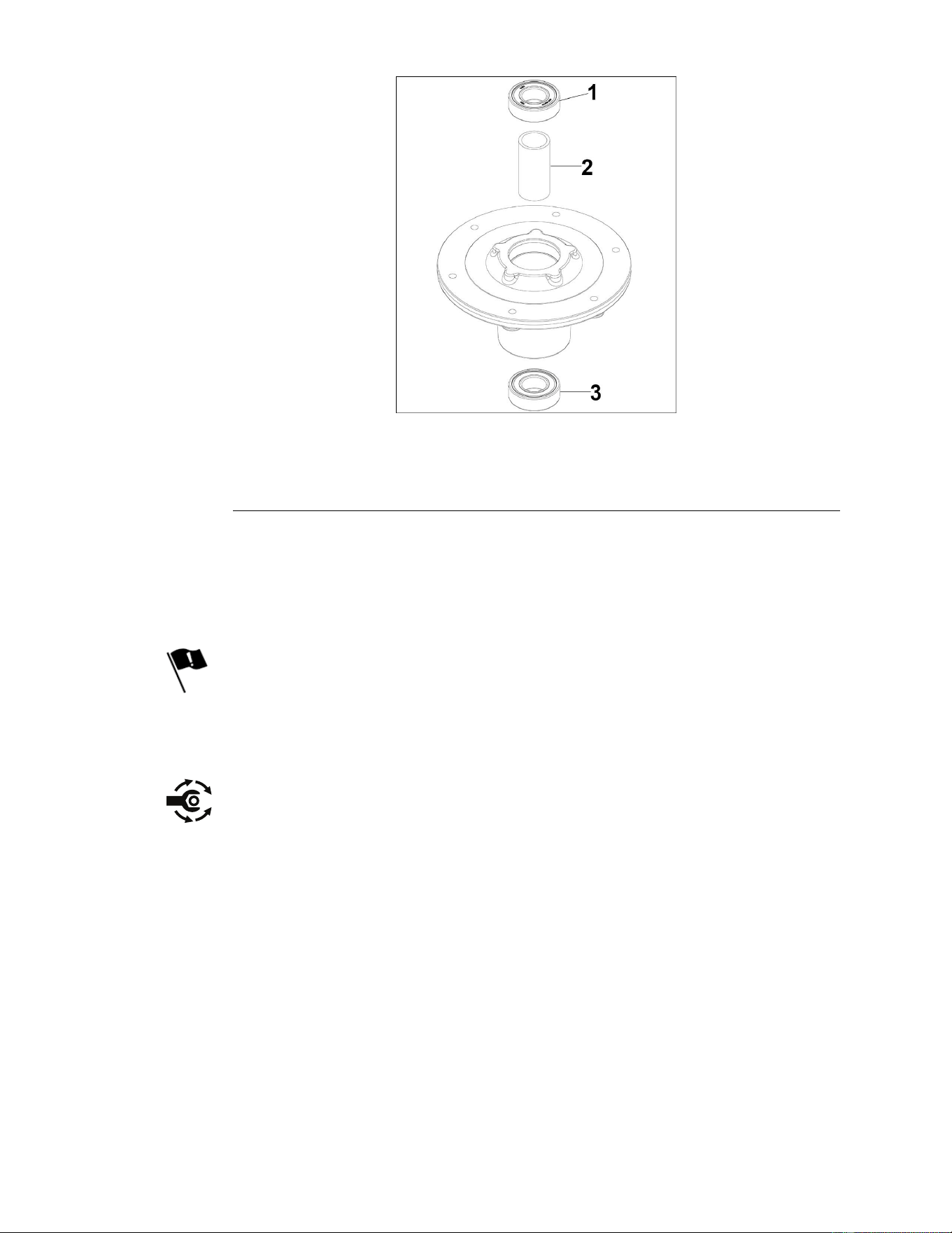
MowerSpindleAssembly(continued)
g322065
Figure80
1.T opBearing3.LowerBearing
2.Spacer
3.Flipthespindlehousingoverandinstallthebearingspacer.
4.Pressthelowerbearingintothespindlehousingbypressingequallyonthe
innerandouterrace.
Note:Theinnerandouterraceontheupperbearingmustbesupported
whileinstallingthelowerbearing.
5.Applyanti-seizetothespindleshaftandinstallthespindleshaft.
6.Flipthespindleoverwhilesupportingtheshaftthroughthespindlehousing.
7.Installthebearingshield.
8.Installthepulley.
MowerDeck:ServiceandRepairs
Page7–10
TitanServiceManual
3438-774RevA
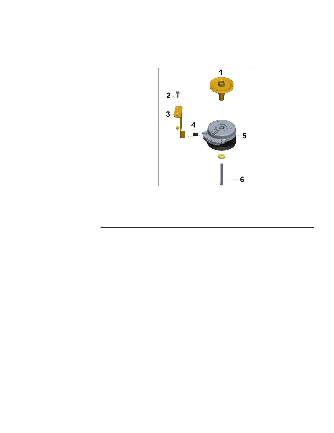
MowerSpindleAssembly(continued)
9.Installthewasherandnut.T orquethetopnutto138-152N•m(100-110ft-lb).
ElectricPTOClutchReplacement
ElectricPTOClutchRemoval
g322063
Figure81
1.EnginePulleytoShaft(ApplyAnti-Seize)4.ClutchIsolator
2.Bolt
5.PTOClutch
3.ClutchStopMount6.ClutchMountingBolt(ApplyLoctite)
1.ParkthemachineonalevelsurfaceanddisengagethePTO.Stopthe
engine,waitforallmovingpartstostop,andremovekey.
2.Disconnectthebatterybyremovingthenegativecablerst,thenthepositive
cablefromthebattery.
3.Raiseandsupporttheunitsothatthedrivewheelsareofftheground.
4.Removethemowerbelt.
5.Disconnecttheclutchwireconnectorfromtheclutch.
6.Removetheclutchmountingboltandwashers.Sliptheclutchoffofthe
crankshaft.
TitanServiceManual
Page7–11
MowerDeck:ServiceandRepairs
3438-774RevA
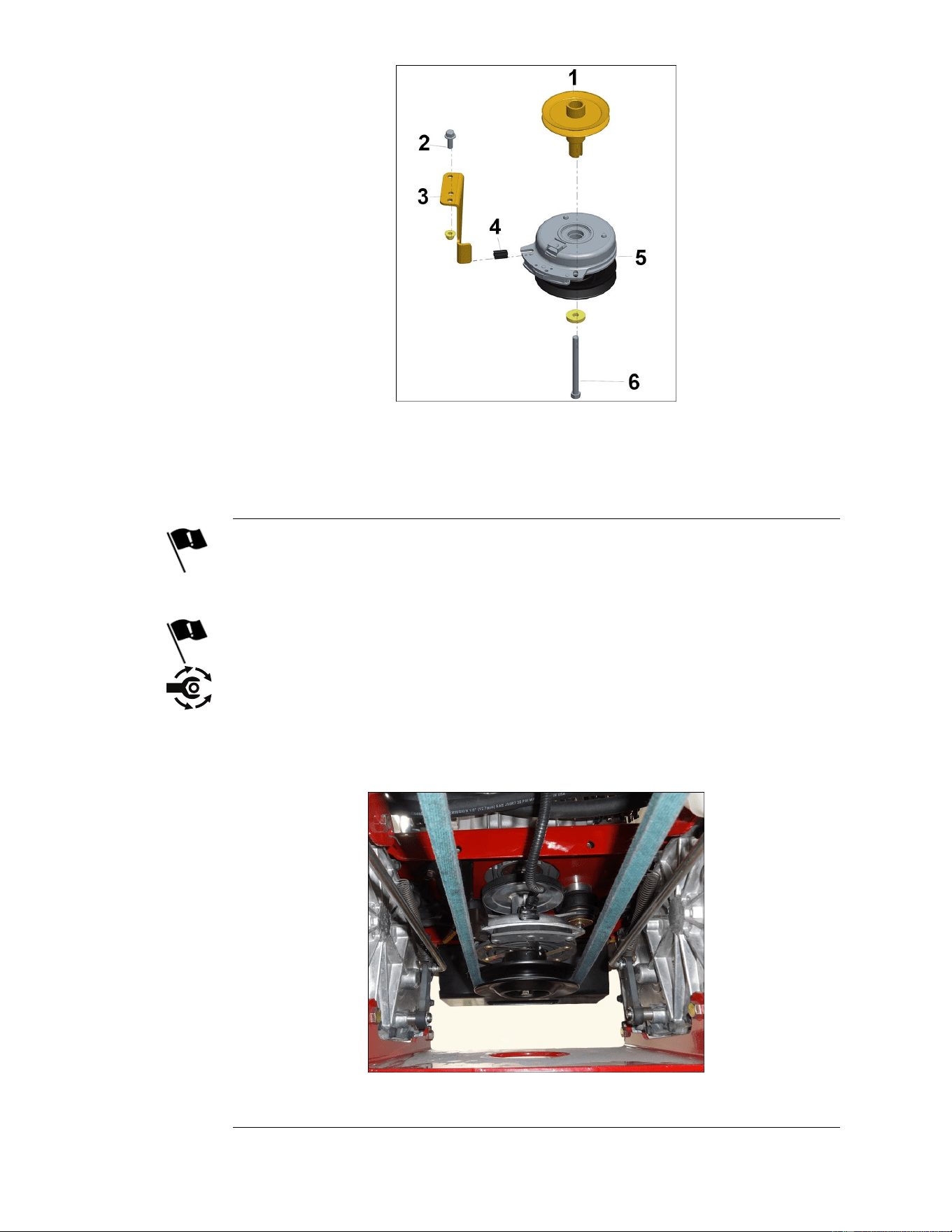
ElectricPTOClutchInstallation
g322063
Figure82
1.EnginePulleytoShaft(ApplyAnti-Seize)4.ClutchIsolator
2.Bolt
5.PTOClutch
3.ClutchStopMount6.ClutchMountingBolt(ApplyLoctite)
1.Installtheclutchontothecrankshaftensuringthattheslotintheclutchaligns
withthetabontheclutchanchorandtherubberisolatorisinplace.
Note:Applyanti-seizetotheendofthepulleyshaft.
2.Applythreadlocktotheclutchbolt.
3.Installthewasherandclutchmountingbolt.T orquetheclutchboltto76±
7N•m(55±5ft-lb).
4.Connecttheclutchpowerwiretotheclutch.
Note:Ensurewireharnessisproperlyroutedtoavoidcontactwiththemower.
g322060
Figure83
MowerDeck:ServiceandRepairs
Page7–12
TitanServiceManual
3438-774RevA


Chapter8
Electrical
TableofContents
GeneralInformation..............................................................................................................................8–2
ServiceandRepairs.............................................................................................................................8–3
FuseBlockandFuses........................................................................................................................8–4
Key/IgnitionSwitch.............................................................................................................................8–4
Hourmeter..........................................................................................................................................8–5
OperatorPresenceSwitch(SeatSwitch)...........................................................................................8–6
NeutralSwitch—LeftandRight........................................................................................................8–6
ParkingBrakeSwitch.........................................................................................................................8–6
StarterSolenoid.................................................................................................................................8–7
PTOSwitch........................................................................................................................................8–8
ElectricPTOClutch............................................................................................................................8–9
TVSDiode........................................................................................................................................8–11
MagnetoStopRelay........................................................................................................................8–11
TitanServiceManual
Page8–1
Electrical
3438-774RevA

GeneralInformation
1.Alwaysuseadigitalmulti-meterforelectricaltestingproceduresandrecord
voltagereadingresults.
2.Beforeperforminganyelectricaltroubleshooting,always:
•Verifyproperbatteryvoltage(above12.4volts):Batteriesreading12.4
voltsorlessareconsidereddischarged
•Checkthatallengineandchassisgroundwiresaresecurelyconnected
andnotdamaged.
3.Useoftestlightsandcontinuitytestersmayresultinfalsereadingsand
leadtoanincorrectdiagnosis.
4.Occasionally,electricaltestingrequirestheuseofajumperwiretobypassa
safetyinterlockswitch,allowingthetechniciantocontinuetroubleshootingby
takingtheswitchoutofthecircuit.
Note:Jumperwiresshouldbeusedfortroubleshootingonly,NEVERleave
ajumperwireinplacetobypassasafetycircuit.
Electrical:GeneralInformation
Page8–2
TitanServiceManual
3438-774RevA
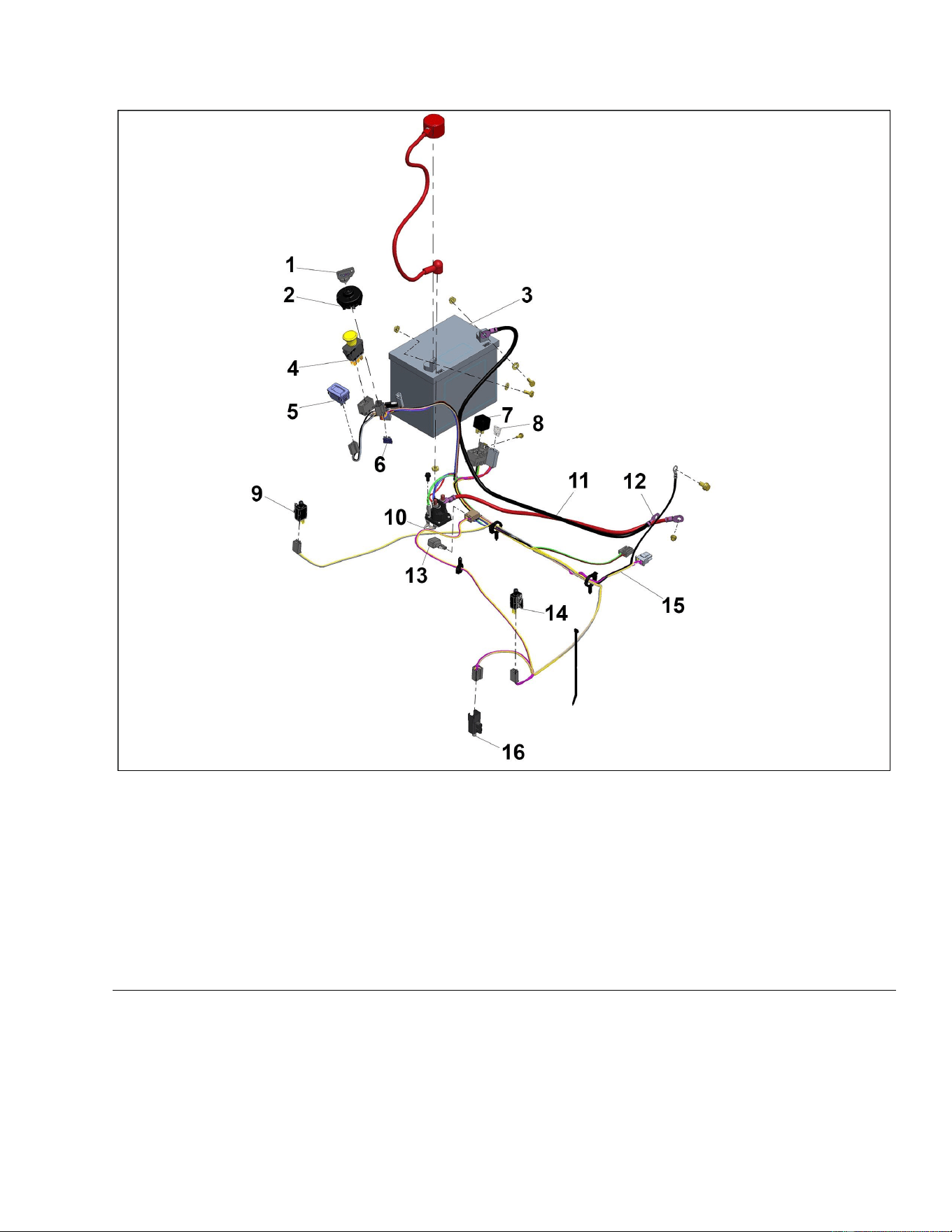
ServiceandRepairs
ElectricalSystemAssembly
g322300
Figure84
1.IgnitionKey
9.NeutralSwitch
2.IgnitionSwitch10.Solenoid
3.Battery
11.NegativeCable
4.PTOSwitch12.EngineGround
5.Hourmeter
13.ClutchDiode
6.15AFuse
14.NeutralSwitch
7.MagnetoStopRelay
15.WireHarness
8.25AFuse
16.ParkBrakeSwitch
TitanServiceManual
Page8–3
Electrical:ServiceandRepairs
3438-774RevA
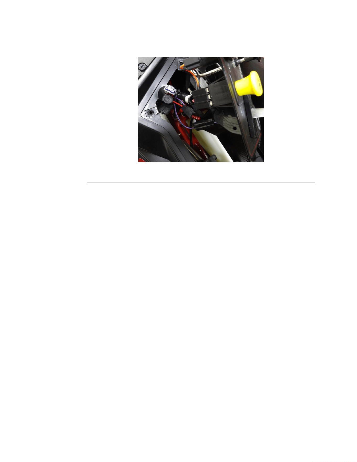
FuseBlockandFuses
Thefuseblockhousesthefusesthatprotecttheelectricalsystemfromelectrical
surges.
Note:AlwaysuseTorofuseswhenreplacingadamagedorblownfuse.
g322165
Figure85
FuseBlockandFusesTesting
1.VisualInspection:Thefusesusedinthisapplicationmaybevisually
inspected.Afailedfusecanbeidentiedbyabrokenormeltedelement
insidethefusecoveroradamagedspade.
2.Usingadigitalmulti-metersettotheOHMorContinuitysetting,removethe
fuseandcheckthecontinuitybetweenthefuseblades.IfthefuseisOPEN
(nocontinuity),replacethefuseandtestthecircuit.
Key/IgnitionSwitch
Theignitionswitchmakestheproperconnectionsforthestarter,safety
circuits,andaccessories.Detentsinsidetheswitchcontrolthethreeswitch
positions:OFF,RUN,andSTART .TheSTARTpositionisspringloadedsothatit
automaticallyreturnstotheRUNpositionwhenreleased.
IgnitionSwitchWiringConnections
Key/IgnitionSwitchTesting
1.ParkthemachineonalevelsurfaceanddisengagethePTO.Stoptheengine,
waitforallmovingpartstostop,andremovekey.Engagetheparkingbrake
2.Removethecontrolpanelfromtherightconsole.
3.Disconnecttheharnessfromtheignitionswitch.Gentlyrocktheconnector
backandforthuntilunplugged.
4.Usingadigitalmulti-metersettotheOHMorContinuitysetting,verifythat
continuityexistsbetweentheterminalslistedforeachswitchposition.
Electrical:ServiceandRepairs
Page8–4
TitanServiceManual
3438-774RevA
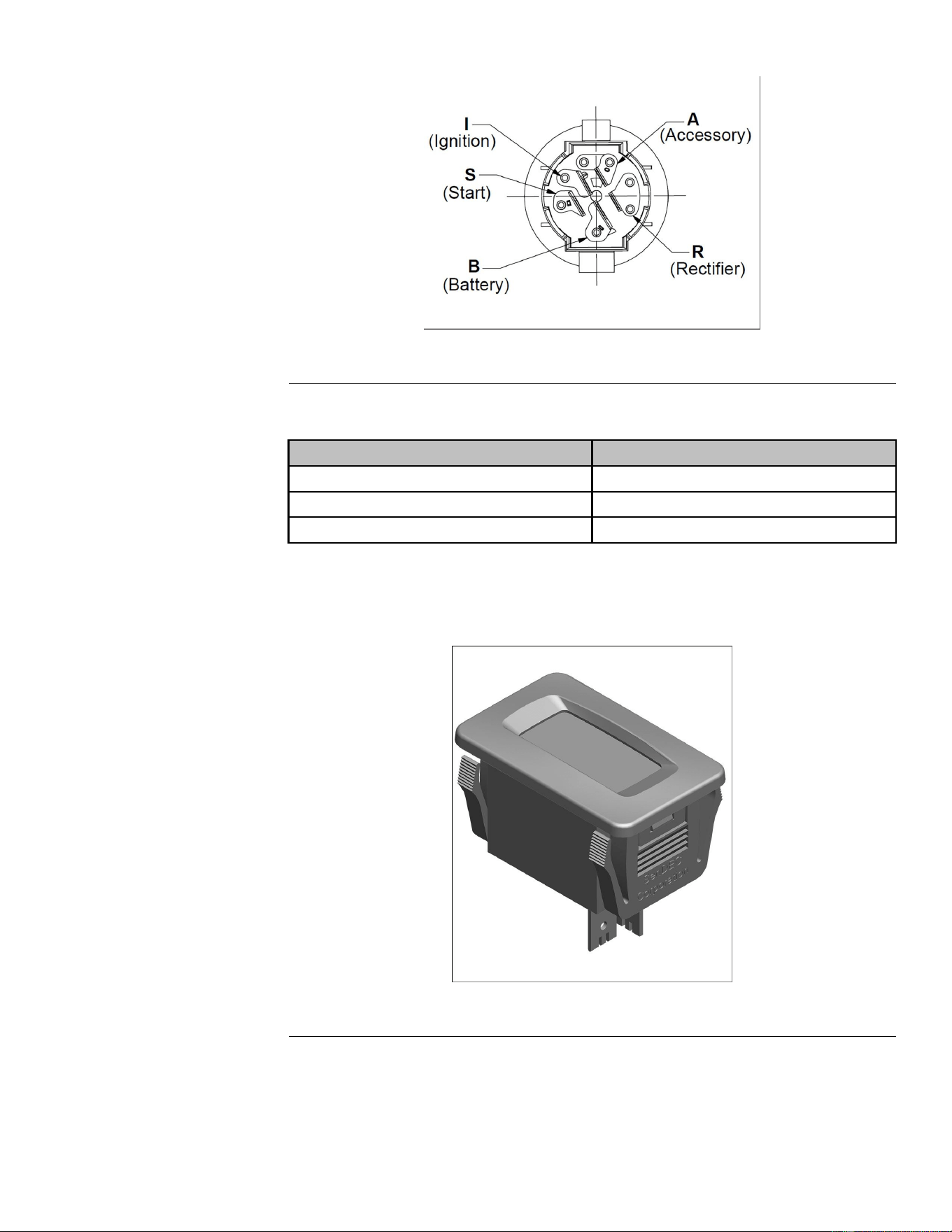
Key/IgnitionSwitchTesting(continued)
g331211
Figure86
5.Usingadigitalmulti-metersettotheOHMorContinuitysetting,verifythat
NOcontinuityexistsbetweentheterminalsnotlistedforeachswitchposition.
Position
Circuit“Make”
1.OFF
None
RunB+R+I+A
3.StartB+R+I+S
Hourmeter
ThehourmeterrecordshoursofoperationwhentheignitionkeyisONandthe
PTOswitchisON.
g322162
Figure87
HourmeterTesting
1.Withoutstartingtheengine,withtheignitionswitchinthe“RUN”position
andthePTOswitchclosed(ON)verifythebatteryvoltageandgroundto
thehourmeter.
TitanServiceManual
Page8–5
Electrical:ServiceandRepairs
3438-774RevA
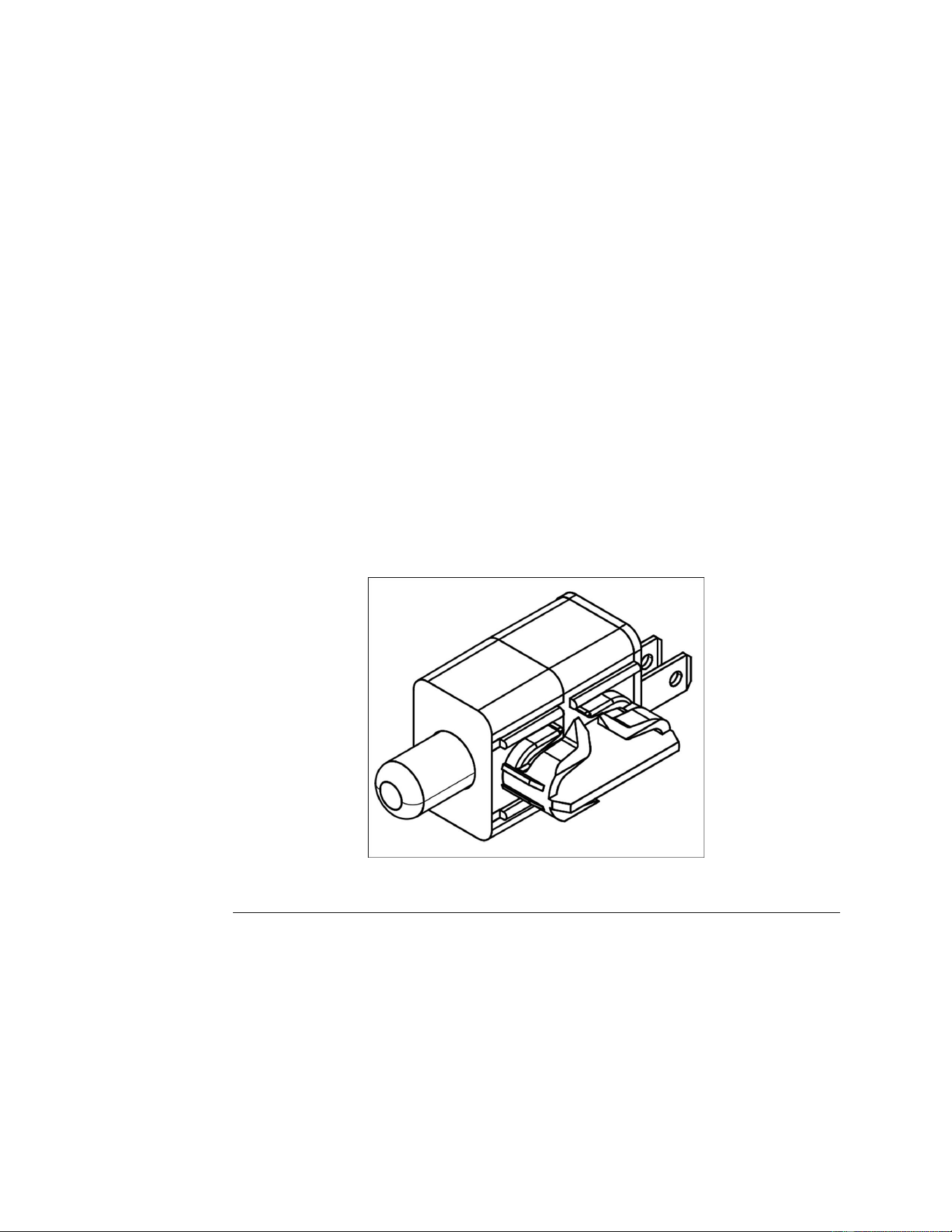
OperatorPresenceSwitch(SeatSwitch)
WiththeignitionswitchintheRUNposition,andtheoperatorpresenceswitch
closed(operatorisintheseat),batteryvoltageissuppliedtothelefthandneutral
switch.
Note:Theoperatorpresenceswitchispartoftheseatassembly.
OperatorPresenceSwitch(SeatSwitch)Testing
1.Disconnectthewireharnessfromtheoperatorpresenceswitch,located
onthebottomoftheseatassembly.
2.Usingadigitalmulti-metersettotheOHMorContinuitysetting,testthe
continuitybetweenthe2switchterminals.
•Whentheseatisvacated,theswitchshouldNOThavecontinuity(open).
•Whentheoperatorispresent,theswitchshouldhavecontinuity(closed).
NeutralSwitch—LeftandRight
•Theneutralswitchisasinglepoleplungertypeswitch(normallyopen)with
twoterminals.Whentheplungerisdepressed,thecircuitclosesandthere
iscontinuitybetweentheterminals.
•Motioncontrolleversinneutralposition(OUT),theswitchshouldhave
continuity(closed).
•Motioncontrolleversintheoperatingposition(IN),theswitchshouldNOT
havecontinuity(open).
g322163
Figure88
ParkingBrakeSwitch
•Theparkingbrakeswitchisadualpole/fourterminalplungertypeswitch
(normallyopenandnormallyclosed).Whentheparkingbrakeisset
(engaged),thenormallyclosedpoleoftheswitchisopenandthenormally
openpoleisclosed.Thisallowspropervoltageandgroundsignalpathfor
thesafetyinterlockandPTOoperations.
•ParkingBrakeON,theswitchshouldhavecontinuity(closed).
•ParkingBrakeOFF,theswitchshouldNOThavecontinuity(open).
Electrical:ServiceandRepairs
Page8–6
TitanServiceManual
3438-774RevA
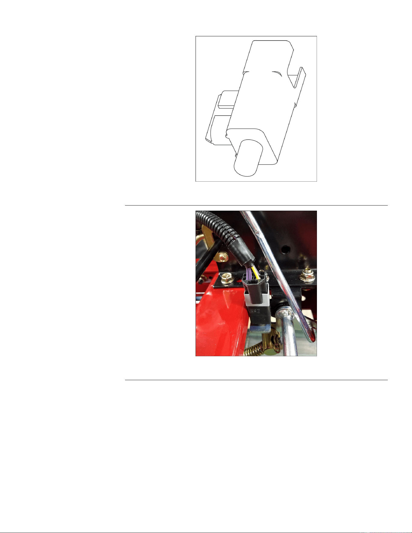
ParkingBrakeSwitch(continued)
g322166
Figure89
g322160
Figure90
StarterSolenoid
Thesolenoidisaremoteswitchthatconnectsthebatterytothestartermotor
whentheignitionswitchisturnedtoSTART .Thesolenoidprotectstheignition
switchfromthehighcurrentdrawnbythestartermotor.
TitanServiceManual
Page8–7
Electrical:ServiceandRepairs
3438-774RevA
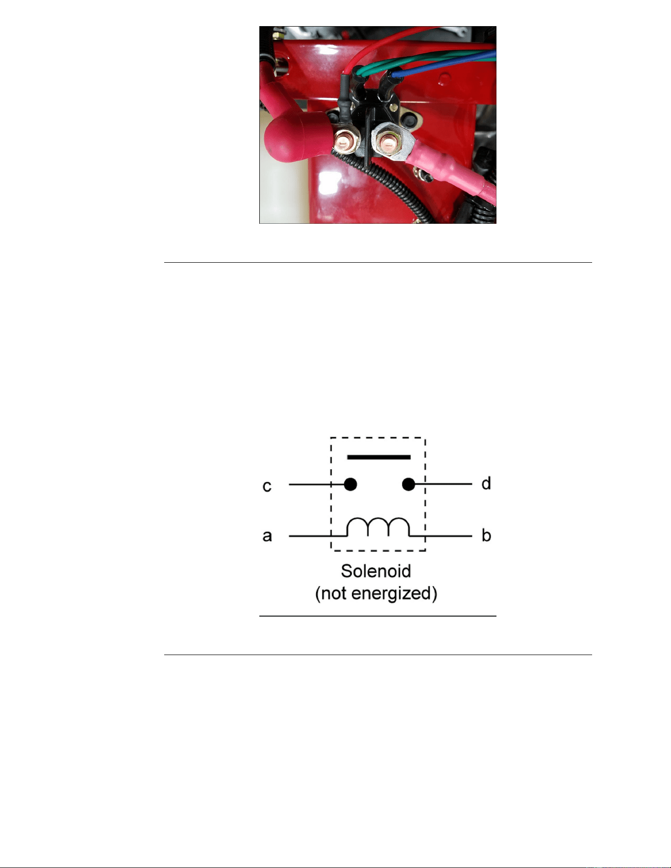
g322159
Figure91
StarterSolenoidTesting
1.Disconnectthebatterycablesfromthesolenoid.
2.Withamulti-metersettotheOHMorContinuitysetting,checktoensurethat
terminalsCandDareopen(nocontinuity).
•GreenwireisterminalB
•BluewireisterminalA
•LargeredwirewithredcapandextraredwireisterminalC
•LargeredwirewithnocapisterminalD
g331279
Figure92
3.Apply12volts(DC)toterminalAandgroundterminalB.T erminalsCandD
shouldnowbeclosed(continuity).
PTOSwitch
ThePTOswitchprovidesbatteryvoltagefromtheignitionswitchtothePTO
clutch.
Aspartofthesafetyinterlocksystem,thePTOswitchwillpreventtheengine
fromcranking/startingwhenintheONpositionbypreventingthestartersolenoid
fromgroundingthroughthekillrelay.
Electrical:ServiceandRepairs
Page8–8
TitanServiceManual
3438-774RevA
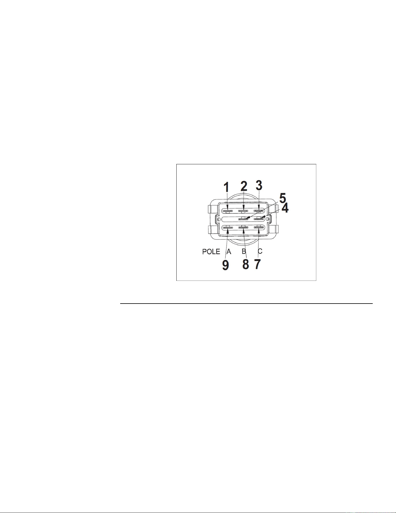
Note:NOTE:TheenginewillnotcrankoverwhenthePTOswitchisinthe
ONposition.
ThePTOswitchprovidesbatteryvoltagefromtheignitionswitchtotheparking
brakeswitchandtheneutralswitchesaspartofthesafetyinterlocksystem.
PTOSwitchTesting
1.Removethecontrolpanelfromtherightconsole.
2.DisconnectthePTOswitchfromthewireharness.
3.WiththeswitchintheONposition(buttonpulledOUT).
4.Usingadigitalmulti-metersettotheOHMorContinuitysetting,verifythe
following:
•Pin2and5shouldhavecontinuity(closed)
•Pin1and4shouldhavecontinuity(closed)
•Pin1and7shouldNOThavecontinuity(open)
•Pin2and8shouldNOThavecontinuity(open)
g331212
Figure93
5.WiththeswitchintheOFFposition(buttonpushedIN)
•Pin1and7shouldhavecontinuity(closed)
•Pin2and8shouldhavecontinuity(closed)
•Pin1and4shouldNOThavecontinuity(open)
•Pin2and5shouldNOThavecontinuity(open)
ElectricPTOClutch
ThePTOclutchelectronicallycontrolstheengagementanddisengagement
ofthePTOpulley(deckbelt).
ThePTOclutchiscomposedofthreemajorcomponents:
•Coil
•Clutchplate
•Frictionplate
Theclutchplatealwaysturnswiththeengine(crankshaft).Theeldisacoilof
wireonanironcorewhichbecomesanelectromagnetwhenpowerisapplied.
Thefrictionplateistheonlypiecethatmovesverticallyonthecrankshaft.Itis
normallyspringloadedsothatitisnotincontactwiththeclutchplateandis
TitanServiceManual
Page8–9
Electrical:ServiceandRepairs
3438-774RevA
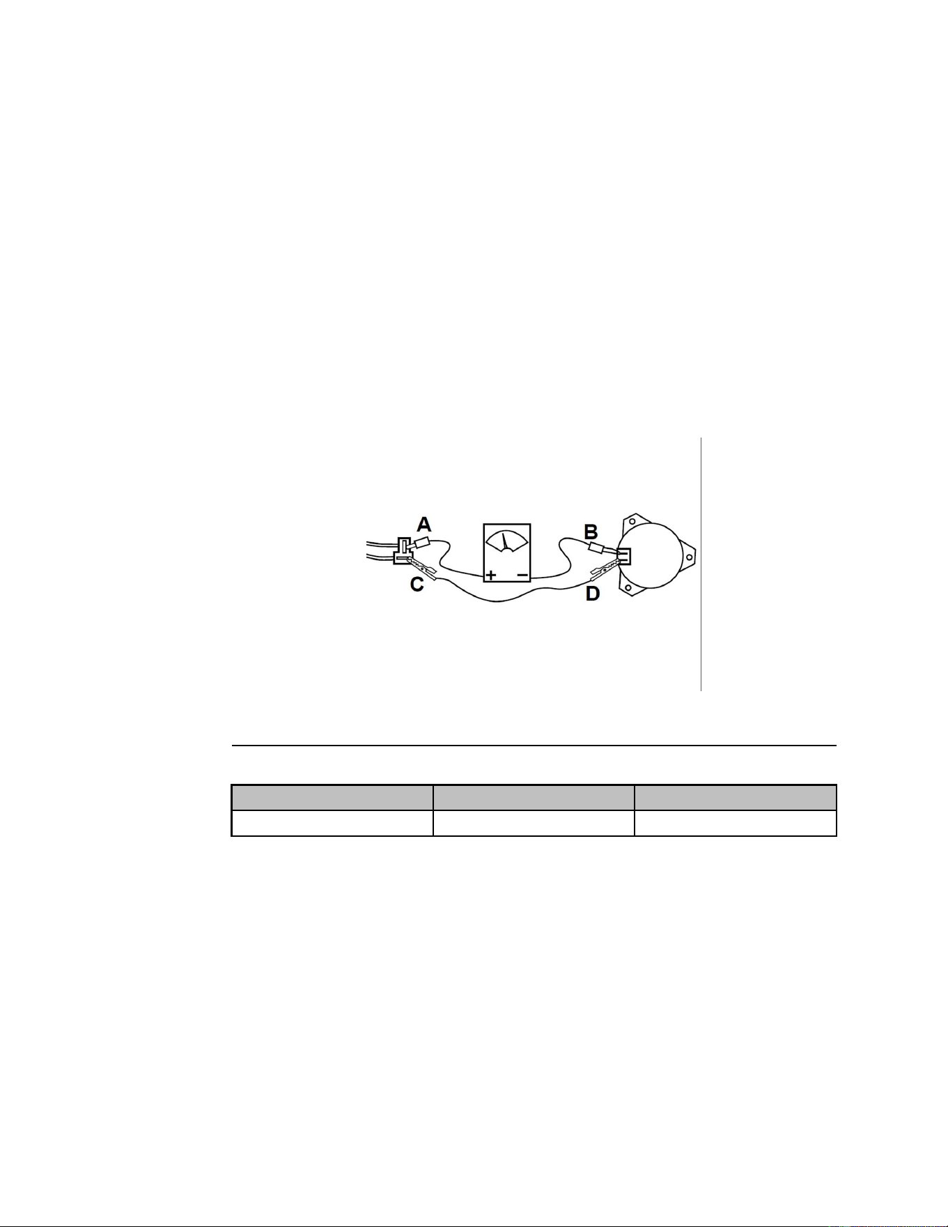
pressedagainstthebrakematerialoppositetheclutchplate.Whenpoweris
applied,thefrictionplateispulledtowardtheclutchplateandthetworotateas
one.Whentheclutchplateandthefrictionplaterotateasdifferentspeedsit
isknownasclutchslipping.
ElectricPTOClutchTesting
IfthePTOclutchisnotengagingorissuspectasacauseofelectricalproblems,
usethefollowingelectricaltroubleshootingsteps.Theseprocedureswillhelp
determineiftheclutchhasfailedasaresultoforisthecauseofanelectrical
problem.
ElectricPTOClutchCoilResistanceMeasurement
1.ParkthemachineonalevelsurfaceanddisengagethePTO.Stopthe
engine,waitforallmovingpartstostopandremovethekey.Engagethe
parkingbrake.
2.Disconnecttheclutchwireconnector.
3.Setthemulti-metertomeasureresistance(OHMssetting).
4.Connectthemeterleadwirestotheterminalsintheclutchconnector.
g331210
Figure94
5.SeethePTOClutchElectricalSpecicationschart.
Resistance(OHMs)
AMPDraw
ContinuitytoGround
3.05±5%
3.93
OPEN
ElectricPTOClutchContinuitytoGroundCheck
1.ParkthemachineonalevelsurfaceanddisengagethePTO.Stopthe
engine,waitforallmovingpartstostopandremovethekey.Engagethe
parkingbrake
2.Disconnecttheclutchwireconnector.
3.Setthemulti-metertomeasureresistance(OHMsetting).
4.Connectonemulti-meterleadtotheclutchhousing.Connecttheother
multi-meterleadtoeachoftheclutchconnectorterminals.
5.The2clutchconnectorterminalsshouldneverhavecontinuitytoground
andshouldOPENatalltimes.
6.IfcontinuityisfoundbetweenthePTOconnectorandground,thePTOclutch
andthePTOswitchmustbereplaced.
Electrical:ServiceandRepairs
Page8–10
TitanServiceManual
3438-774RevA
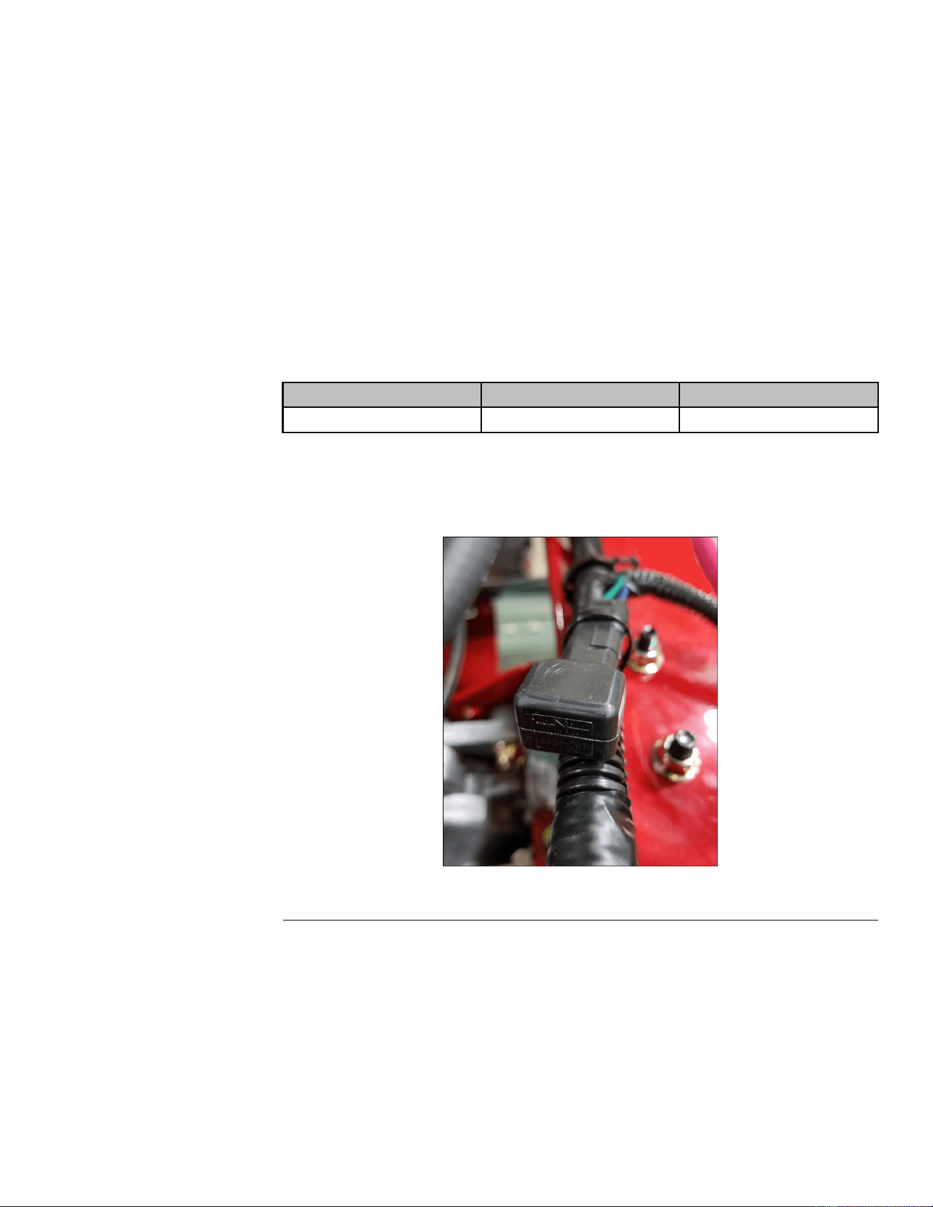
MeasuringClutchCurrentDraw
Note:Donotmeasurecurrentdrawiftheclutchhasshortedtogroundorifthe
resistancemeasurementisoutofspecication.
1.ParkthemachineonalevelsurfaceanddisengagethePTO.Stopthe
engine,waitforallmovingpartstostop,andremovethekey.Engagethe
parkingbrake.
2.Disconnecttheclutchwireconnector.
3.Setthemulti-metertomeasureamps(10ampscale).
4.ConnectthepositivemeterleadtothechassisharnessterminalA.
5.Connectthenegativemeterleadtothecorrespondingclutchterminal.
6.ConnectashortjumperleadfromterminalC(largeredwirewithcap)to
terminalD(largeredwirewithnocap).
7.TurntheignitionswitchtoRUNandthePTOswitchtotheONposition.
8.RecordtheampreadingandrefertothePTOClutchElectricalSpecication
Chart.
Resistance(OHMs)
AMPDraw
ContinuitytoGround
3.05±5%
3.93
OPEN
TVSDiode
TheTVSDiodeprotectstheelectricalsystemfromcurrentsurgescausedby
PTOengagementanddisengagement.
g322161
Figure95
TVSDiodeTesting
Notestingprocedureavailable.Ifthediodeissuspectedtobefaulty,replacethe
diode.Ifthesystemfuseblowseachtimetheclutchisengaged,theTVSdiode
ismorethanlikelyshortingclutchpowertoground.
MagnetoStopRelay
Themagnentostoprelaygroundsthemagnetowhenthekeyisturnedtothe
“OFF”position.Whenthekeyisturnedtothe“RUN”position,thesolenoidis
TitanServiceManual
Page8–11
Electrical:ServiceandRepairs
3438-774RevA


AppendixA
FoldoutDrawings
TableofContents
ElectricalDrawingAbbreviations........................................................................................................A–2
ElectricalSchematic...........................................................................................................................A–3
TitanServiceManual
PageA–1FoldoutDrawings
3438-774RevA

ElectricalDrawingAbbreviations
Thefollowingabbreviationsareusedforwireharnesscolorsontheelectrical
schematicsandwireharnessdrawingsinthischapter.
Abbreviation
Color
BKBlack
BRorBNBrown
BUBlue
GNGreen
GYGray
ORorOGOrange
PKPink
RorRDRed
TorTNT an
VIOorVT
Violet
WorWHWhite
YorYEYellow
Numerousharnesswiresincludealinewithanalternatecolor.Thesewiresare
identiedwiththewirecolorfollowedbya/or_andthenthelinecolor(e.g,R/BK
isaredwirewithablackline;OR_BKisanorangewirewithablackline).
Note:Theelectricalharnessdrawingsinthischapteridentifyboththewirecolor
andthewiregauge.Forexample,16BKonaharnessdiagramidentiesa
16gaugewirewithblackinsulation.
Note:Aspliceusedinawireharnesswillbeidentiedonthewireharness
diagrambySP .Themanufacturingnumberofthespliceisalsoidentiedonthe
wireharnessdiagram(e.g.,SP01issplicenumber1).
FoldoutDrawingsPageA–2
TitanServiceManual
3438-774RevA
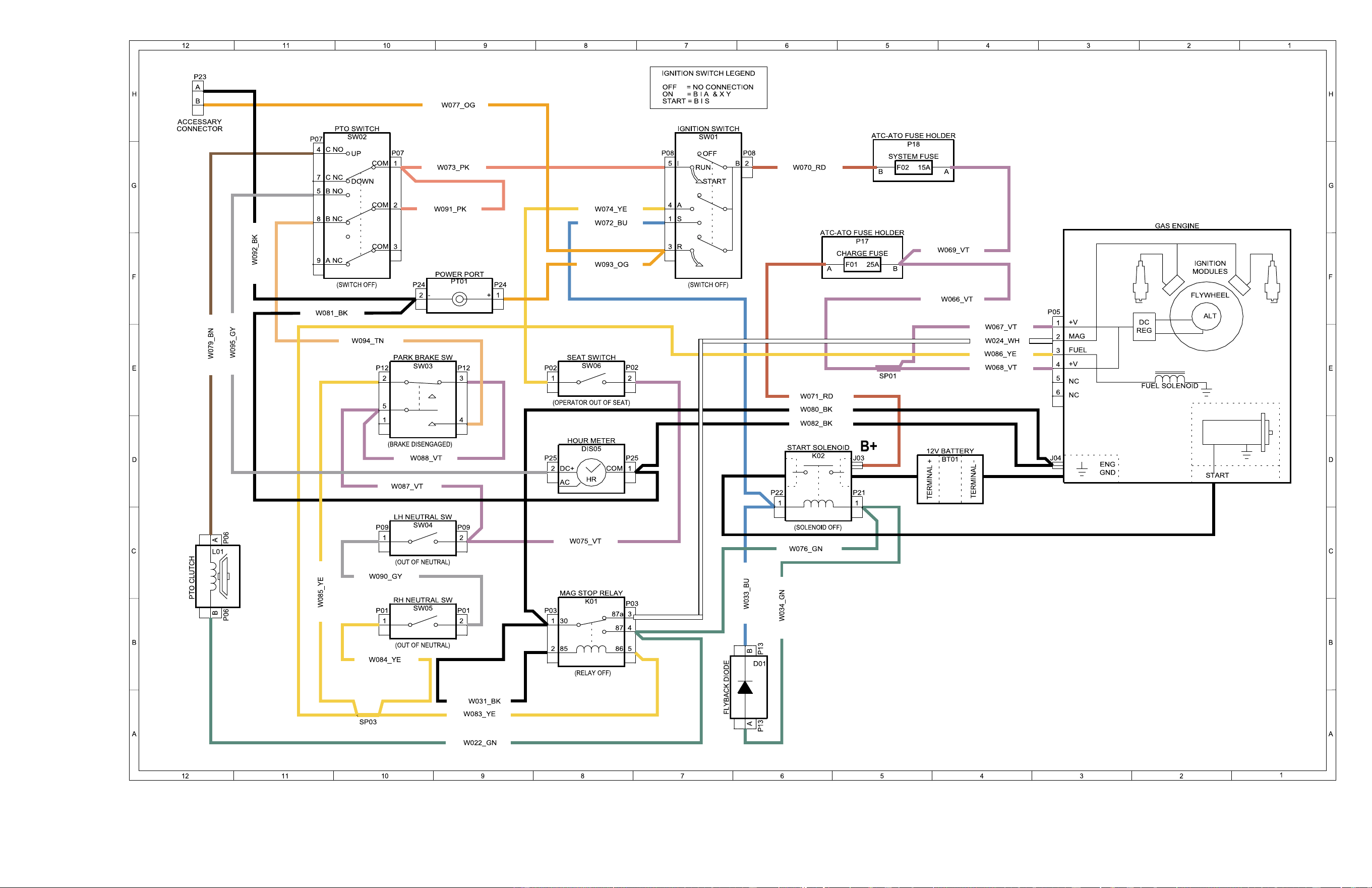
,DrawingRevA,Sheet1
3438-774RevA
PageA–3
ElectricalSchematic
g322167