
Technical Support and E-Warranty Certificate www. vevor. com/support
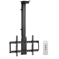
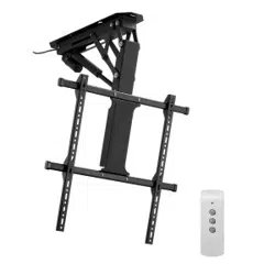
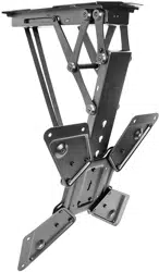
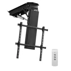
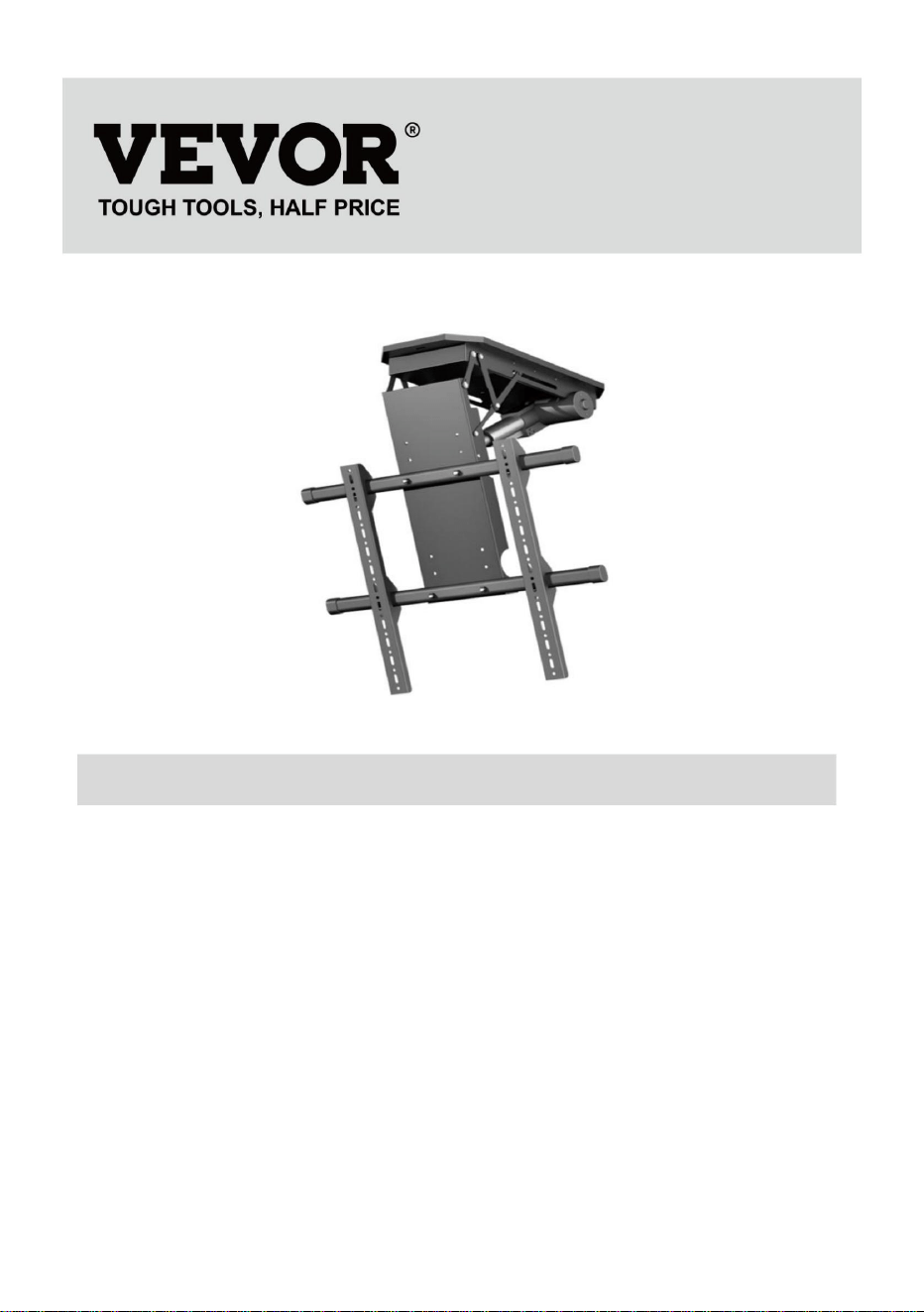
TV LIFT
USER MANUAL
MODEL: DT680-A
We continue to be committed to provide you tools with competitive price.
"Save Half", "Half Price" or any other similar expressions used by us only
represents an estimate of savings you might benefit from buying certain tools
with us compared to the major top brands and does not necessarily mean to cover
all categories of tools offered by us. You are kindly reminded to verify carefully
when you are placing an order with us if you are actually Saving
Half in comparison with the top major brands.


1
MODEL: DT680-A
NEED HELP? CONTACT US!
Have product questions? Need technical support? Please feel free to
contact us:
Technical Support and E-Warranty Certificate
www.vevor.com/support
This is the original instruction, please read all manual instructions
carefully before operating. VEVOR reserves a clear interpretation of our
user manual. The appearance of the product shall be subject to the
product you received. Please forgive us that we won't inform you again if
there are any technology or software updates on our product.
TV LIFT
2
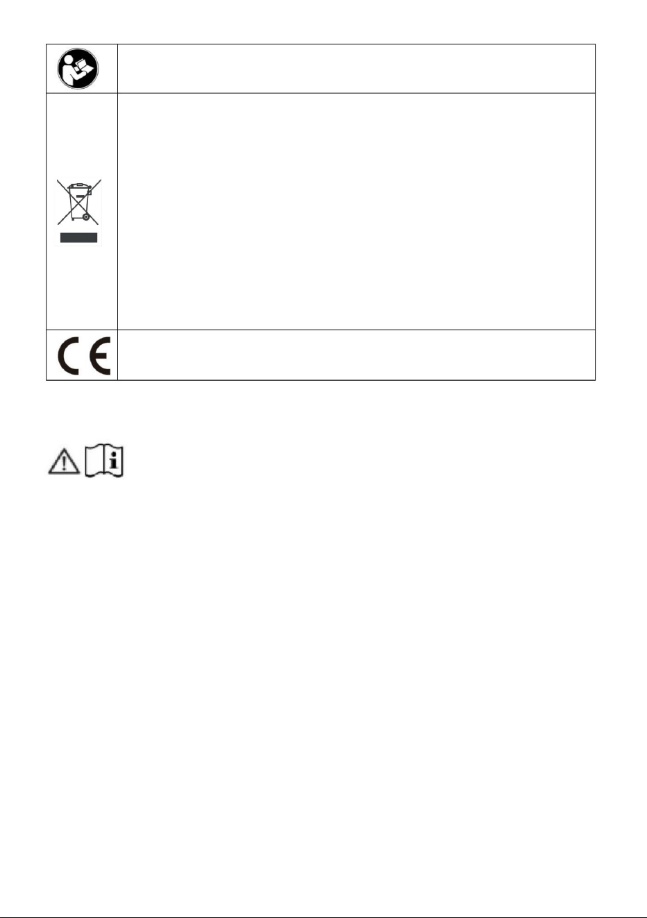
Warning-To reduce the risk of injury, user must read
instructions manual carefully.
CORRECT DISPOSAL
This product is subject to the provision of european Directive
2012/19/EU. The symbol showing a wheelie bin crossed
through indicates that the product requires separate refuse
collection in the European Union. This applies to the product
and all accessories marked with this symbol. Products
marked as such may not be discarded with normal domestic
waste, but must be taken to acollection point for recycling
electrical and electronic devices.
Compliance is a CE security certification.
IMPORTANT SAFEGUARDS
Please read and understand this entire manual before
attempting to assemble, operate or install the product. Failure
to follow all instructions listed below may result in electric shock, fire and/or
serious injury.
WARNING:
1. The load added onto the actuator must be less than or equal to the
rated load of actuator.
2. Please use the 29V DC power adapter.
3. All actuators have duty cycle, they cannot work all the time without
stopping.
4. The actuator is not completely waterproof, please do not immerse it in
water directly.
5. Children shall not play with the appliance. Cleaning and user
maintenance shall not be made by children without supervision.
SAVE THESE INSTRUCTIONS
3
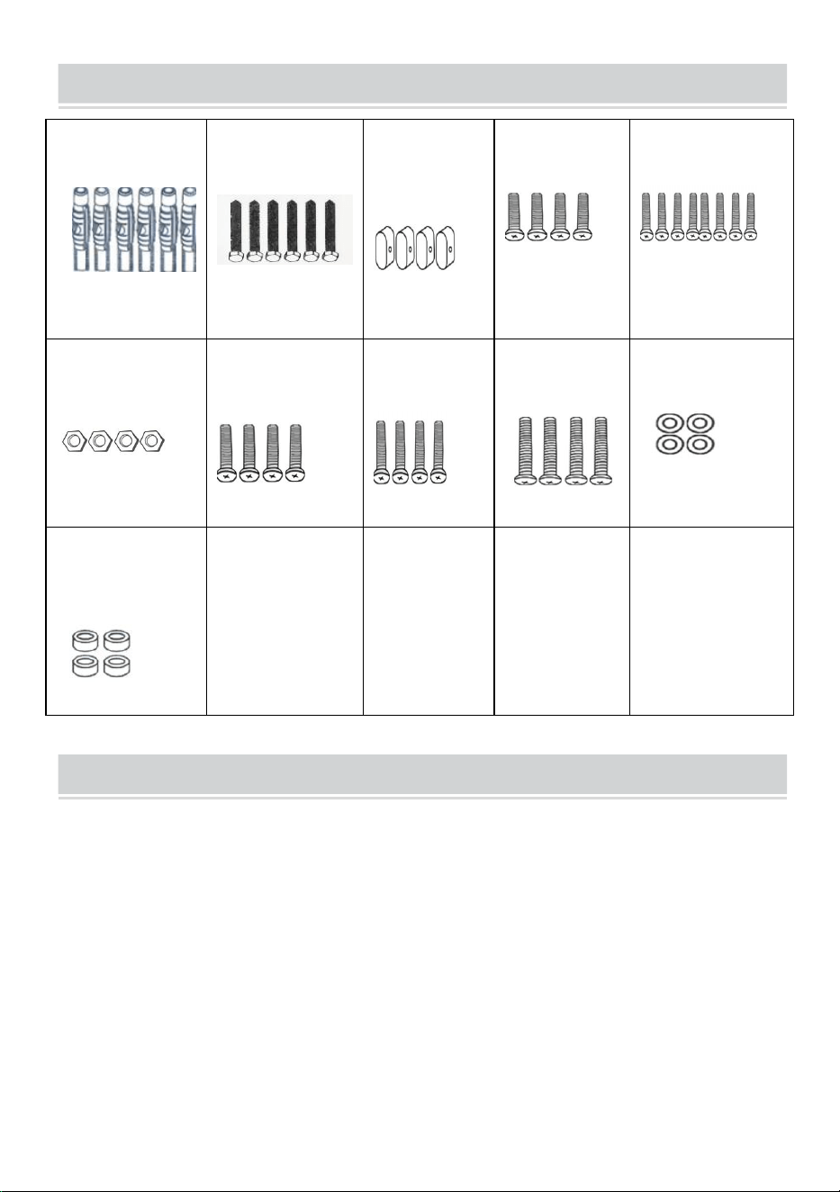
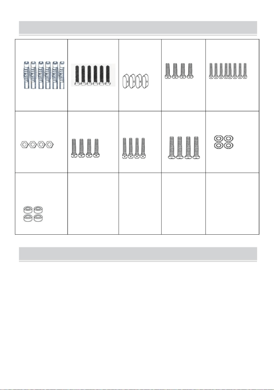
PARTS LIST
A
Φ7*Φ10*60mm
6PCS
B
M7*60
6PCS
C
Blanking
Cap
4PCS
D
M5*10mm
4PCS
E
M6*30mm
8PCS
F
M6
4PCS
G
M6*10mm
4PCS
H
M4*20mm
4PCS
I
M8*30mm
4PCS
J
Φ8*Φ17*1.7mm
4PCS
K
Cylindrical
Sleeve
4PCS
ATTENTION
1. Please ensure that the screws and nuts are tightened during installation.
For your safety, the product must be used in the specified size and weight
limits.
2. Ensure that the wall's quality and load-bearing capacity are sufficient for
installation. The manufacturer is not responsible for any consequences
arising from improper installation.
3. If installing in glass or glass curtain wall, foam brick, marble, fiberboard
board, please consult a professional installer before installation. Otherwise,
the manufacturer is not responsible for any consequences caused by
improper installation!
4
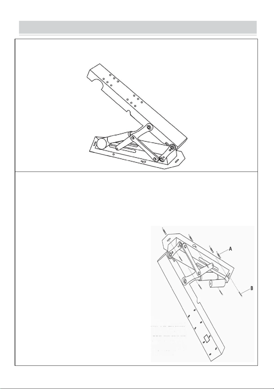
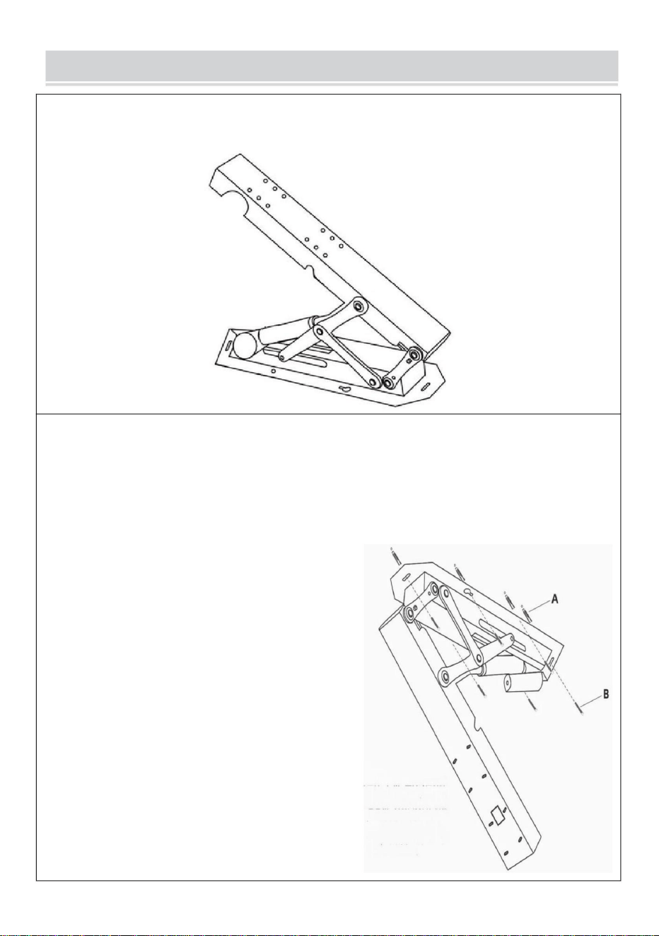
INSTRUCTIONS
STEP 1
Power on the main body of the support and adjust it to open state.
STEP 2
Position the support wall plate, mark the hole locations, and drill the
holes. Insert the expansion tubes into the holes, and insert the
expansion screw through the wall plate to fix the main body of the
support.
Installation tips:
Screw the expansion screws into the
left and right gourd holes about
halfway (1/2), then position the
support body over the screws through
the large hole in the gourd.
Temporarily suspend the support by
aligning it with the empty hole position.
Next, insert the expansion screws into
the remaining four positions. Finally,
tighten all the expansion screws to
complete the installation, making the
process easier.
5
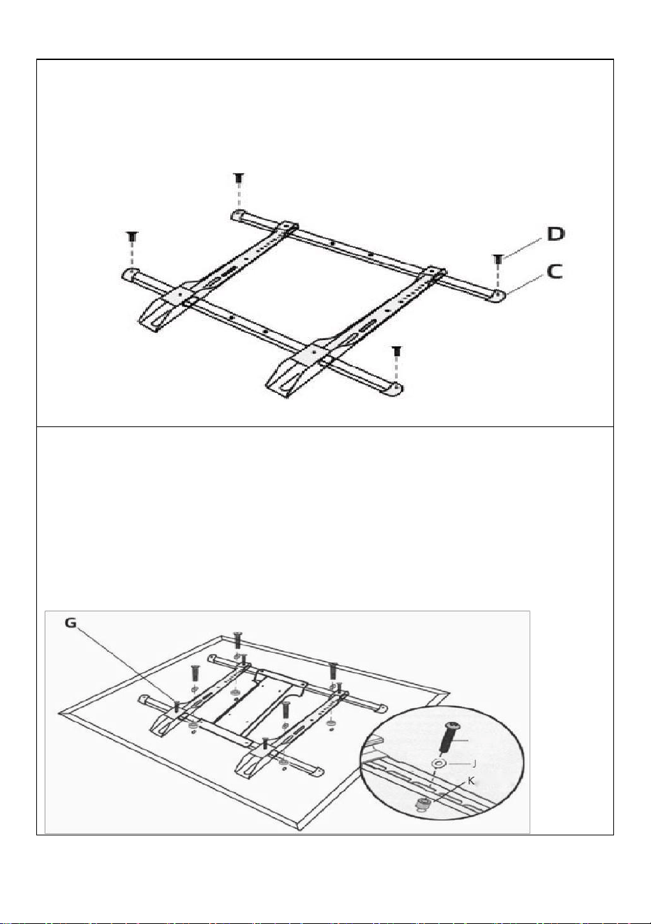
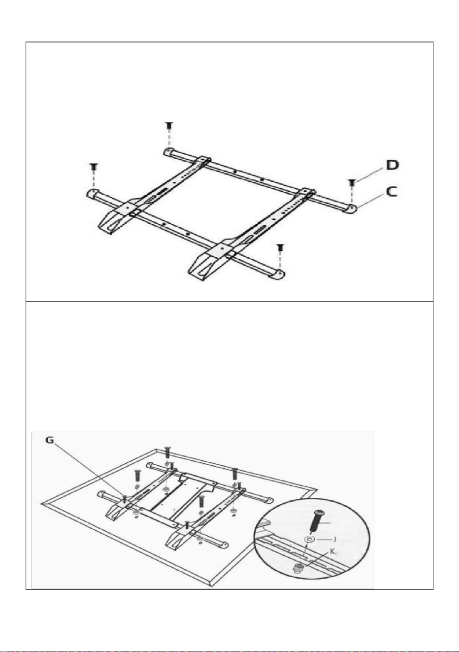
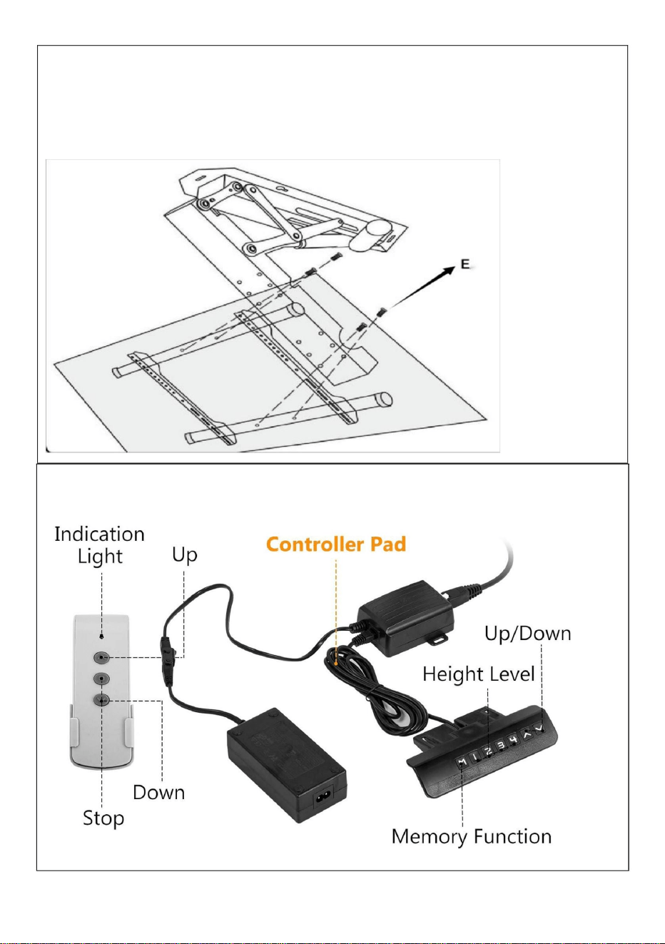
STEP 3
Insert the two beams into the two holes on the upper and lower sides
of the hook, and secure the plugs at both ends of the beams by using
screws.
STEP 4
Connected TV
①
Select the appropriate holes for the two vertical hooks of the
assembled tic-tac-stand, and connect the tic-tac-stand with the holes
on the back of the TV.
②
Install the safety screws above and below the two hooks
respectively.
H/I
6
STEP 6
Connection adapter
STEP 5
Install TV
As shown in the picture: Connect the 4 holes of the TV holder and the
holes at the front of the main body with 4 screws.
7
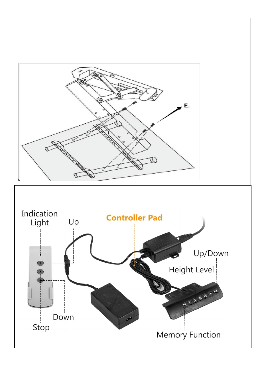
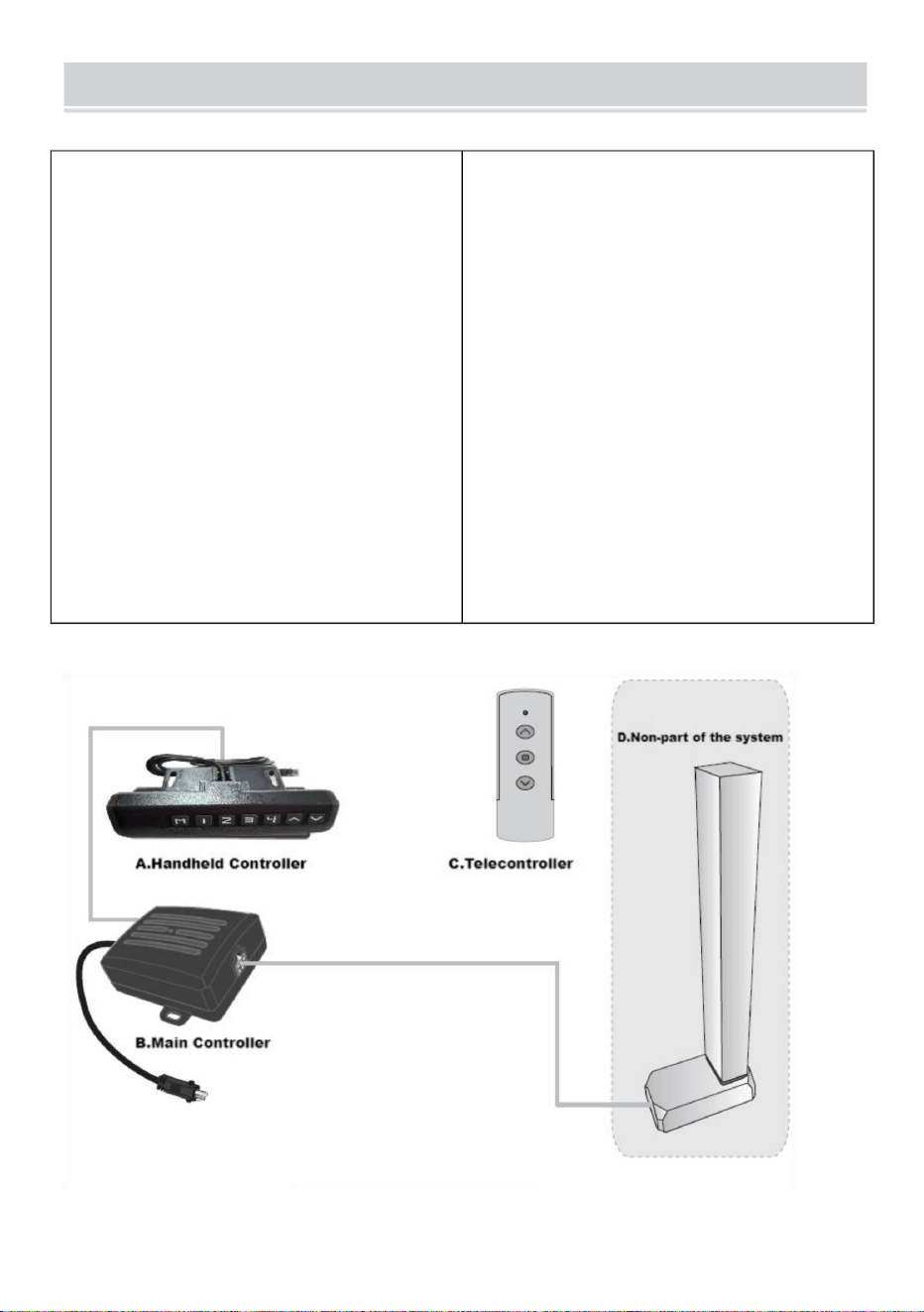
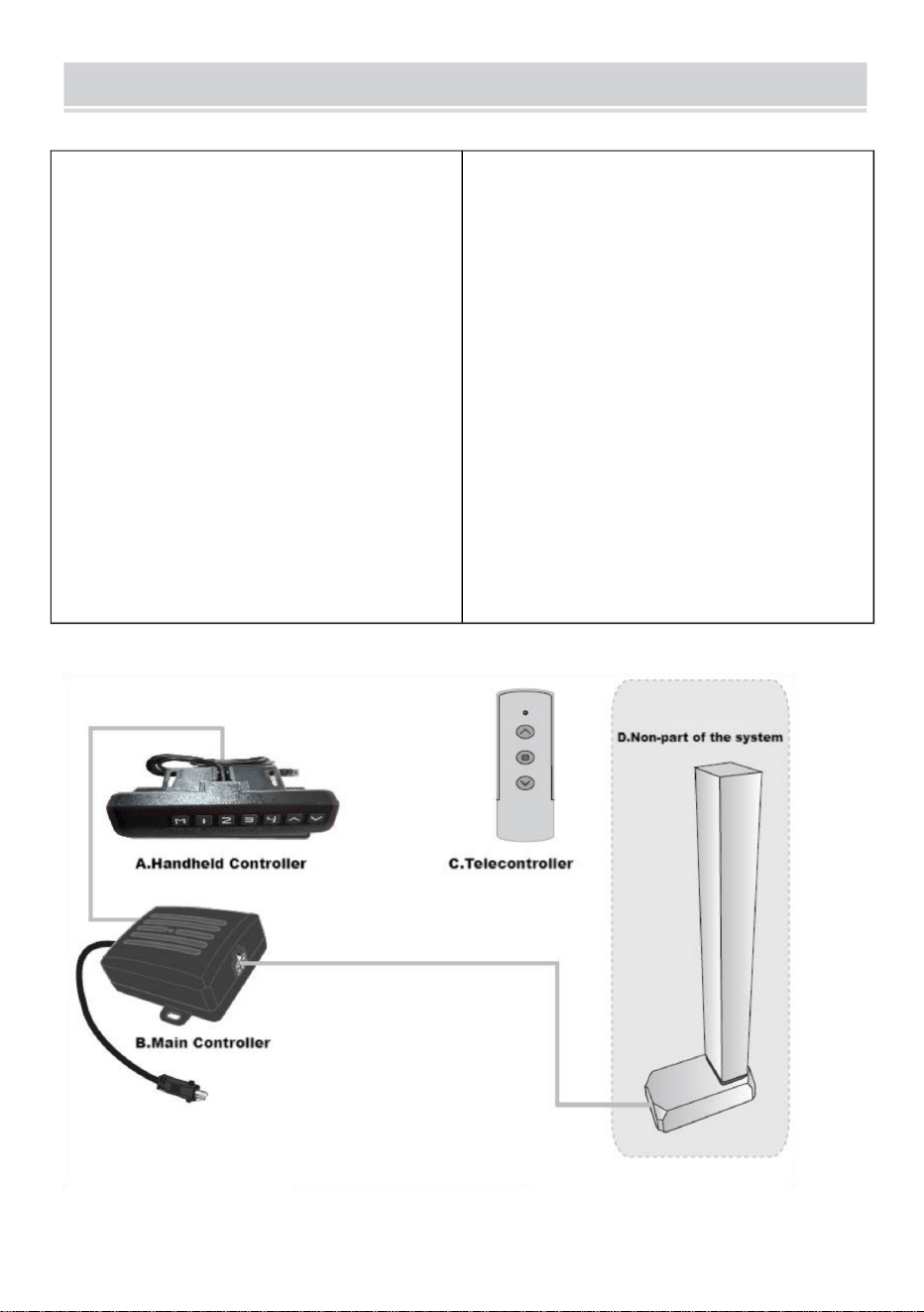
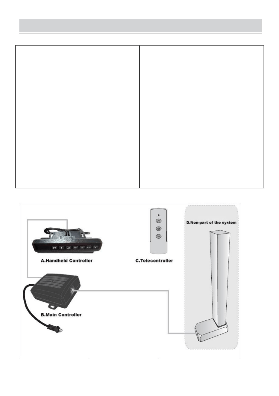
Controller Instruction Manual
I. Function introduction
Intelligent single column controller
has the following characteristics:
1.It can control two motors` output
to achieve synchronous operation;
2.Indicator light displays the
fault,reseting;
3.Controlled by up and down
buttons;
4.Wireless remote
control(alternative).
II. System parameters
1.Input voltage:DC29V;
2.Input current: recommending
above 1.8A and according to the
load;
3.Maximum output voltage of motor
interface:DC29V;
4.Maximum output current of motor
interface:4A;
5.Operating temperature:0~40
℃
6.Working humidity:20~90%;
7.Storage temperature:20~70℃.
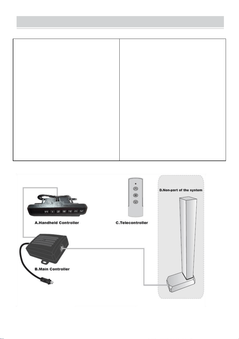
III. System connection

8
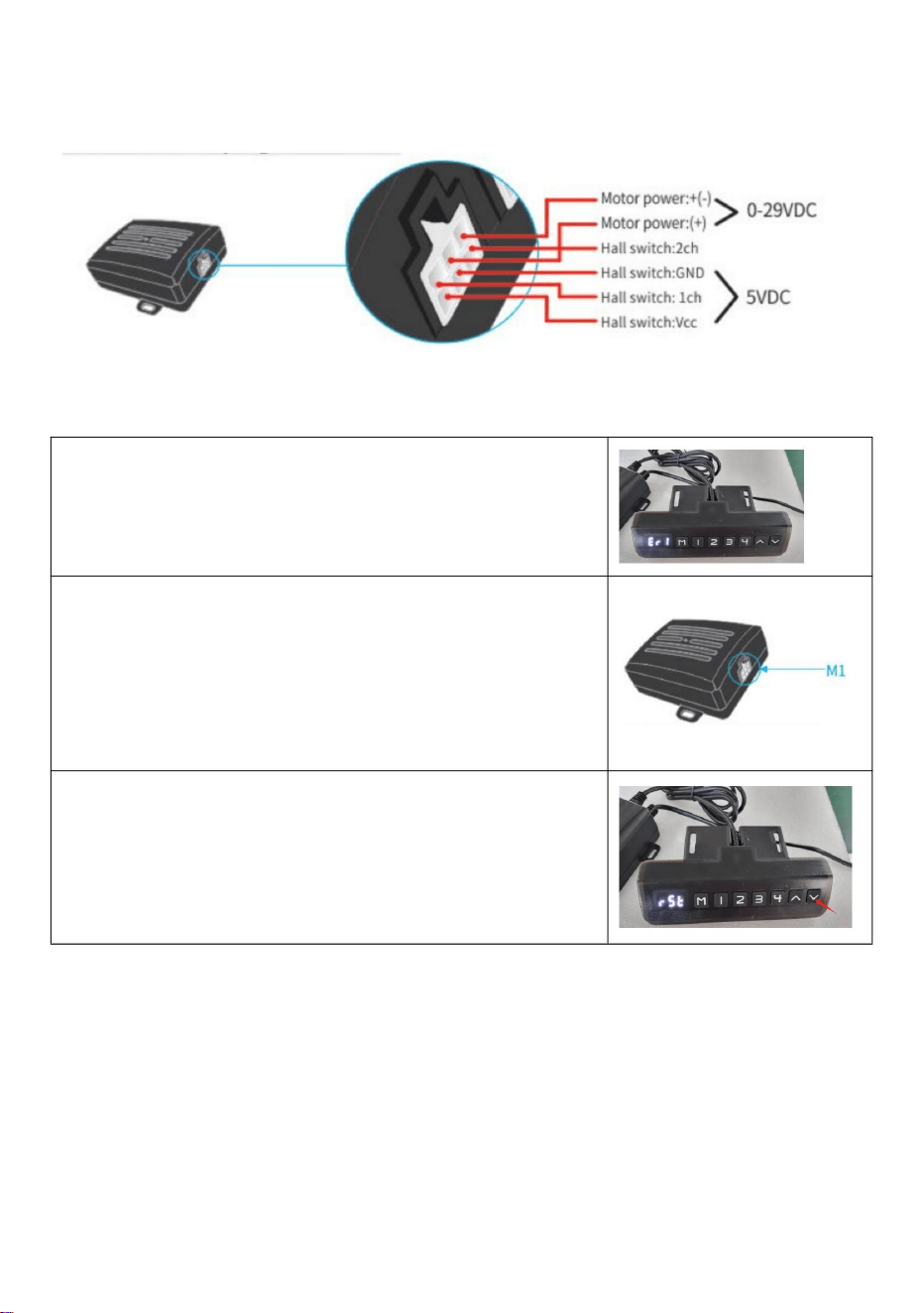
IV. Motor interfase plug definition:
V. Fault code and its treatment
1.Fault code Err1
When the manual controller shows Er1, it's a fault of
Err1. It means there is something wrong with M1
interface channel (see the following picture).F or
exemple m otors are not connected in a positive way;
Hall signal board is not connected;Paper line,etc.
After the issue is resolved, press the "down" button for
more than 3 seconds to clear the fault, and the
machine will return to reset state.

9
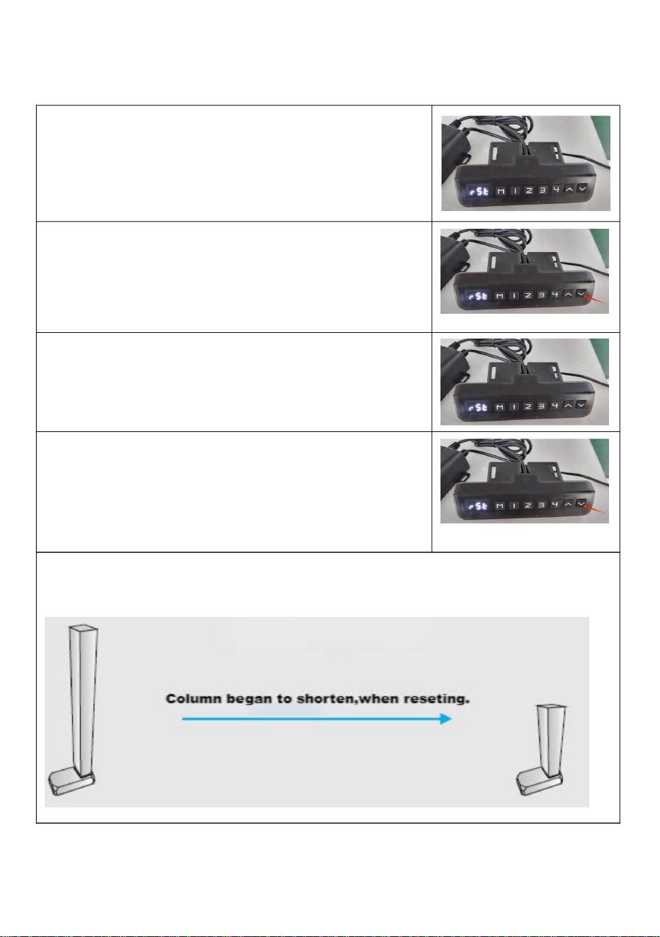
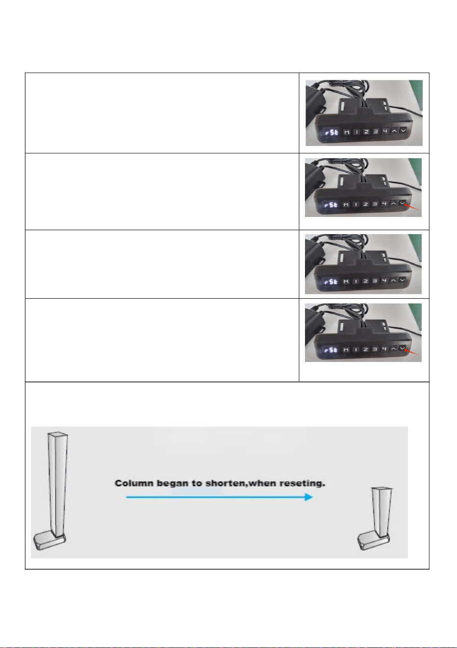
VI. System reset
1.Prompt reset
When the manual controller indicator light always
stays on (see the following picture), it means it is
reseting. The whole system needs to reset maunally.
2.Line reset
When the manual controller shows the minimum
heigh ,pressing″down button″ more than 5 seconds
and the indicator light is on .It means reseting.
Releasing the hand and starting to reset system,after
the manual controller indicator light is on.
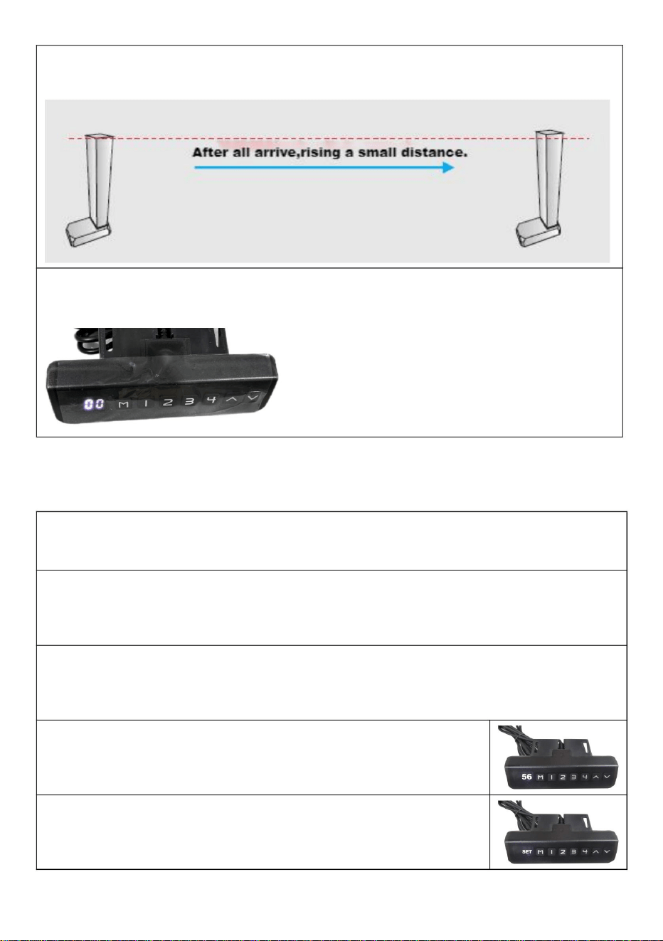
3.Reset method
When the manual controller indicator light always
stays on ( see the following figure), pressing the "down
" button″ and do not release it.
The column may begin to shorten, and the speed could slow down. Observe for
any other damage during operation; if there is any, stop immediately.

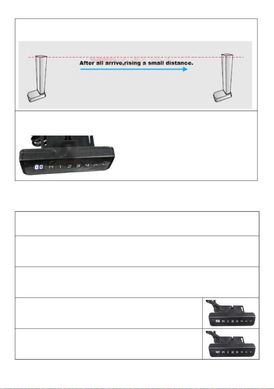
10
The colunm will rise 5~10mm after a short time when it reach the lowest
point.
When the manual controller indicator light is off(see the following
picture),releasing the hand and end at resetting.
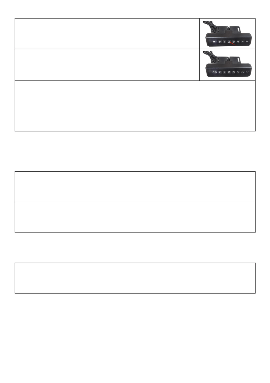
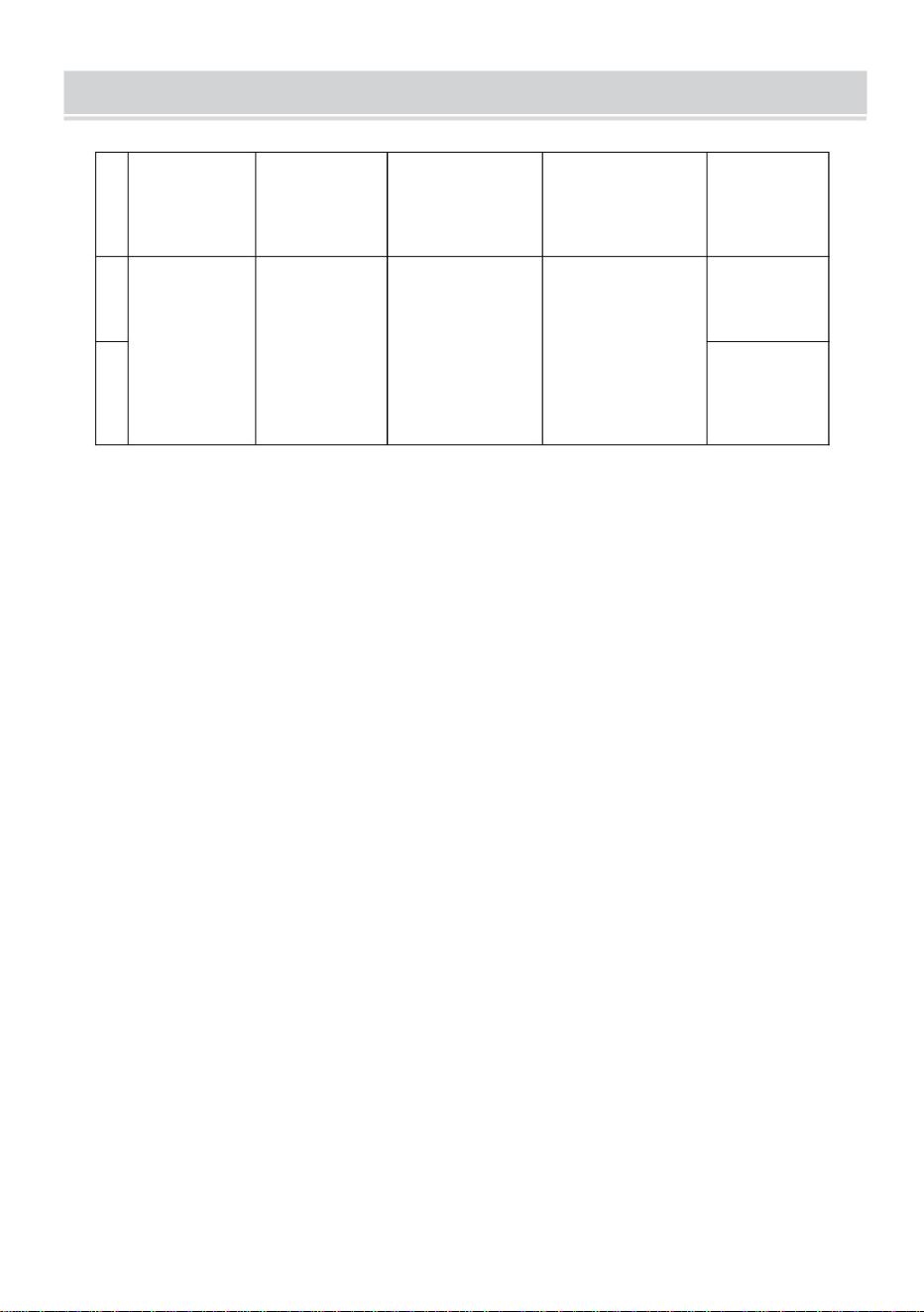
VII. Preset target height
1.Preset target height quantity:
The system provides 4 groups of preset height storage
2.Preset target height data erasure:
The erasing function is not configured separately. When a new parameter
is set, the system automatically erases the old parameter.
3.Preset target height operation method:
At any height (reset state, cannot perform this operation in error state), the
current height parameter can be preset to keys 1-4.
Example: ①Set the current height 56 to key No. 2
②Press the "M" key to display "SET"

11
③Within 2 seconds, press "2" before "SET" disappears
④The "S-2" preset is displayed. End, the previous
display is restored.
5. Use the method of preset target height:
At any height (reset state, cannot perform this operation in the wrong
state), you can use keys 1-4 to quickly reach the preset target height. If the
current height is already near the preset target height, no action will be
performed.
Ⅷ. Telecontroller operation
1.Matching window period
Matching window period is repowering after 3 seconds.There will be
buzzing sound when the period ends.
2.Right code
In matching window period,passing the ″up button″longly and waiting for 4
long and 3 short intervals of buzzing sound,it means righting code is over.
Ⅸ. Backtracking when encountering obstacles
In addation to the reset state,when working ,the mechanical structure
encounter a sudden changes from loading ,which will cause the contrller to
carry out a fallback operation to prevent external sound of injury.
12
PRODUCT PARAMETERS
Model
Safe
Loading
Weight
Input
Adapter
input voltage
Region
1
DT680-A
110lbs
DC29V
1.8A
100-240V~
50/60Hz
America
2
Europe


MODÈLE:DT680A
MANUELD'UTILISATION
ÉLÉVATEURDETÉLÉVISION
Assistancetechniqueetcertificatdegarantieélectroniquewww.vevor.com/support
«Économisezlamoitié»,«Moitiéprix»outouteautreexpressionsimilaireutiliséepar
nousnereprésentequ'uneestimationdeséconomiesquevouspourriezréaliserenachetant
certainsoutilscheznousparrapportauxgrandesmarquesetnecouvrepasnécessairementtoutes
lescatégoriesd'outilsquenousproposons.Nousvousrappelonsdebienvouloirvérifier
soigneusementlorsquevouspassezunecommandecheznoussivous
économisezréellementlamoitiéparrapportauxgrandesmarques.
Nouscontinuonsànousengageràvousfournirdesoutilsàdesprixcompétitifs.
Machine Translated by Google

Machine Translated by Google

BESOIND'AIDE?CONTACTEZNOUS!
Ils'agitdelanoticed'utilisationd'origine.Veuillezlireattentivementtoutesles
instructionsdumanuelavantdel'utiliser.VEVORseréserveledroitd'interpréterclairement
notremanueld'utilisation.L'apparenceduproduitdépendduproduitquevousavez
reçu.Veuilleznousexcuser,nousnevousinformeronsplusencasdemiseàjourtechnologique
oulogicielledenotreproduit.
MODÈLE:DT680A
Vousavezdesquestionssurnosproduits?Vousavezbesoind'assistancetechnique?
N'hésitezpas
ànouscontacter:Assistancetechniqueetcertificatdegarantie
électroniquewww.vevor.com/support
ÉLÉVATEURDETÉLÉVISION
1
Machine Translated by Google

MESURESDESÉCURITÉIMPORTANTES
CONSERVEZCESINSTRUCTIONS
AvertissementPourréduirelerisquedeblessure,l'utilisateurdoitlire
déchet,maisdoitêtreapportéàunpointdecollectepourrecyclage
l'entretiennedoitpasêtreeffectuépardesenfantssanssurveillance.
marquéscommetelsnepeuventpasêtrejetésaveclesdéchetsdomestiquesnormaux
Lisezattentivementlemanueld'instructions.
appareilsélectriquesetélectroniques.
AVERTISSEMENT:
1.Lachargeajoutéesurl'actionneurdoitêtreinférieureouégaleàla
chargenominaledel'actionneur.
collectedansl'Unioneuropéenne.Cecis'appliqueauproduit
Lenonrespectdetouteslesinstructionscidessouspeutentraînerunchocélectrique,unincendieet/ou
arroserdirectement.
blessuregrave.
ettouslesaccessoiresmarquésdecesymbole.Produits
5.Lesenfantsnedoiventpasjoueravecl'appareil.Nettoyageetutilisation
Veuillezlireetcomprendrel'intégralitédecemanuelavant
2012/19/UE.Lesymbolereprésentantunepoubelleàroulettesbarrée
arrêt.
4.L'actionneurn'estpascomplètementétanche,veuilleznepasl'immergerdans
àtraversindiquequeleproduitnécessiteuntrisélectif
tenterd'assembler,d'utiliseroud'installerleproduit.Échec
LaconformitéestunecertificationdesécuritéCE.
ÉLIMINATIONCORRECTE
2.Veuillezutiliserl'adaptateursecteur29VCC.
3.Touslesactionneursontuncycledeservice,ilsnepeuventpasfonctionnertoutletempssans
Ceproduitestsoumisauxdispositionsdeladirectiveeuropéenne
2
Machine Translated by Google

ATTENTION
D
8pièces
M8*30mm
je
C
4pièces
K
Φ7*Φ10*60mm
H
6pièces
4pièces4pièces
M6
4pièces
M6*30mm
M5*10mm
4pièces
J
Manche
6pièces
M4*20mm
4pièces
M7*60
B
Capuchon
M6*10mm
4pièces
UN
Obturation
G
ET
Φ8*Φ17*1,7mm
F
4pièces
Cylindrique
LISTEDESPIÈCES
3
2.Assurezvousquelaqualitéetlacapacitédechargedumursontsuffisantespour
l'installation.Lefabricantn'estpasresponsabledesconséquencesd'uneinstallation
incorrecte.
Pourvotresécurité,leproduitdoitêtreutilisédansleslimitesdetailleetdepoidsspécifiées.
1.Veuillezvousassurerquelesvisetlesécroussontserréslorsdel'installation.
3.Encasd'installationsurunmurrideauenverreouenverre,surdesbriquesenmousse,
dumarbre,despanneauxdefibres,veuillezconsulteruninstallateurprofessionnelavant
l'installation.Danslecascontraire,lefabricantn'estpasresponsabledesconséquences
d'uneinstallationincorrecte!
Machine Translated by Google

Suspendeztemporairementlesupport
enl'alignantaveclapositiondutrouvide.
Ensuite,insérezlesvisd'expansiondans
lesquatrepositionsrestantes.Enfin,
serreztouteslesvisd'expansionpour
terminerl'installation,cequifaciliterale
processus.
ÉTAPE2
Conseils
d'installation:Vissezlesvisd'expansiondans
lestrousdelagourdegaucheetdroiteà
peuprèsàmichemin(1/2),puis
positionnezlecorpsdesupportsurlesvisà
traverslegrandtroudelagourde.
Mettezsoustensionlecorpsprincipaldusupportetréglezlesurl’étatouvert.
ÉTAPE1
Positionnezlaplaquemuraledesupport,marquezl'emplacementdestrousetpercez
lestrous.Insérezlestubesd'expansiondanslestrousetinsérezlavis
d'expansionàtraverslaplaquemuralepourfixerlecorpsprincipaldusupport.
INSTRUCTIONS
4
Machine Translated by Google

TVconnectée
Sélectionnezlestrousappropriéspourlesdeuxcrochetsverticauxdusupporttictac
assembléetconnectezlesupporttictacauxtroussituésàl'arrièredutéléviseur.
Installezlesvisdesécuritéaudessusetaudessousdesdeuxcrochets
respectivement.
SALUT
vis.
ÉTAPE4
Insérezlesdeuxpoutresdanslesdeuxtroussituéssurlescôtéssupérieuretinférieurducrochet
etfixezlesbouchonsauxdeuxextrémitésdespoutresàl'aide
ÉTAPE3
5
Machine Translated by Google

6
Commeindiquésurl'image:connectezles4trousdusupportTVetlestrousàl'avantdu
corpsprincipalavec4vis.
ÉTAPE6
Installerlatélévision
ÉTAPE5
Adaptateurdeconnexion
Machine Translated by Google

III.Connexiondusystème
5.Températuredefonctionnement:0~40
3.Tensiondesortiemaximaledel'interface
dumoteur:DC29V;
4.Télécommandesans
fil(alternative).
6.Humiditédetravail:20~90%;
II.Paramètresdusystème1.
Tensiond'entrée:29VCC;
2.Courantd'entrée:recommandéau
dessusde1,8Aetenfonctiondela
charge;
4.Courantdesortiemaximaldel'interface
moteur:4A;
Lecontrôleurintelligentàcolonneunique
présentelescaractéristiquessuivantes:
1.Ilpeutcontrôlerlasortiededeuxmoteurs
pourobtenirunfonctionnementsynchrone;
2.Levoyantlumineuxaffichele
défautetla
réinitialisation;3.Contrôlépardes
boutonshautetbas;
I.Présentationdelafonction
7.Températuredestockage:20~70.
Manueld'instructionsducontrôleur
7
Machine Translated by Google
Unefoisleproblèmerésolu,appuyezsurlebouton«bas»pendantplusde
3secondespoureffacerledéfaut,etle
lamachinereviendraàl'étatderéinitialisation.
LorsquelecontrôleurmanuelafficheEr1,ils'agitd'uneerreurErr1.Cela
signifiequ'ilyaunproblèmeaveclecanald'interfaceM1(voir
l'imagesuivante).Parexemple,lesmoteursnesontpasconnectés
demanièrepositive;lacartedesignalHalln'estpasconnectée;laligne
papier,etc.
1.Coded'erreurErr1
V.Coded'erreuretsontraitement
IV.Définitiondelaprised'interfacemoteur:
8
Machine Translated by Google

Relâcherlamainetcommenceràréinitialiserlesystème,après
etlevoyantestallumé.Celasignifielaréinitialisation.
1.Réinitialisationrapide
levoyantducontrôleurmanuelestallumé.
Lorsquelecontrôleurmanuelafficheleminimum
Lacolonnepeutcommenceràseraccourciretlavitessepeutralentir.Observez
toutautredommagependantlefonctionnement;s'ilyena,arrêtezimmédiatement.
hauteur,enappuyantsurlebouton«bas»pendantplusde5secondes
resteallumé(voirlafiguresuivante),enappuyantsurlatouche«bas»
réinitialisation.L'ensembledusystèmedoitêtreréinitialisémanuellement.
2.Réinitialisationdelaligne
«bouton»etnelerelâchezpas.
3.Méthodederéinitialisation
Lorsquelevoyantducontrôleurmanuelesttoujoursallumé
resteallumé(voirl'imagesuivante),celasignifiequ'ilest
Lorsquelevoyantducontrôleurmanuelesttoujoursallumé
NOUS.Réinitialisationdusystème
9
Machine Translated by Google

VII.Hauteurcibleprédéfinie
1.Quantitédehauteurcibleprédéfinie:
Lesystèmefournit4groupesdestockagedehauteursprédéfinies
2.Effacementdesdonnéesdehauteurcibleprédéfinies:
estdéfini,lesystèmeeffaceautomatiquementl'ancienparamètre.
Lorsquelevoyantducontrôleurmanuelestéteint(voircidessous)
image),relâcherlamainetterminerparlaréinitialisation.
indiquer.
Lacolonnes'élèverade5à10mmaprèsuncourtlapsdetempslorsqu'elleatteindraleniveauleplusbas
Àn'importequellehauteur(étatderéinitialisation,impossibled'effectuercetteopérationenétatd'erreur),le
leparamètredehauteuractuelpeutêtrepréréglésurlestouches1à4.
Appuyezsurlatouche«M»pourafficher«SET»
3.Méthodedefonctionnementdelahauteurcibleprédéfinie:
Lafonctiond'effacementn'estpasconfiguréeséparément.Lorsqu'unnouveauparamètre
Exemple:Réglezlahauteuractuelle56surlatouchen°2
10
Machine Translated by Google

.Retourenarrièreencasd'obstacles
.Fonctionnementdutélécontrôleur
5.Utilisezlaméthodedelahauteurcibleprédéfinie:à
n'importequellehauteur(étatderéinitialisation,impossibled'effectuercetteopérationdansunétat
incorrect),vouspouvezutiliserlestouches1à4pouratteindrerapidementlahauteurcibleprédéfinie.Sila
hauteuractuelleestdéjàprochedelahauteurcibleprédéfinie,aucuneactionneseraeffectuée.
2.Codededroite
Danslapériodedefenêtredecorrespondance,enappuyantlonguementsurle«boutonhaut»etenattendant
4intervalleslongset3intervallescourtsdebourdonnement,celasignifiequelecodedecorrectionestterminé.
Lepréréglage«S2»s'affiche.Àlafin,l'affichageprécédentestrestauré.
Dansles2secondes,appuyezsur«2»avantque«SET»nedisparaisse
1.Périodedefenêtredecorrespondance
Lapériodedefenêtredecorrespondanceestréactivéeaprès3secondes.Unbourdonnementretentira
lorsquelapériodeseterminera.
Enplusdel'étatderéinitialisation,lorsdufonctionnement,lastructuremécaniquesubitdeschangements
soudainsdecharge,cequiamèneralecontrôleuràeffectueruneopérationdesecourspourévitertoutbruit
externepouvantcauserdesblessures.
11
Machine Translated by Google
Amérique
1
Sûr
DC29V
Saisir
2
Europe
Région
50/60Hz
Chargement
Poids
DT680A110lb
1,8A
Tension
d'entréedel'adaptateur
Modèle
100240V~
PARAMÈTRESDUPRODUIT
12
Machine Translated by Google

Machine Translated by Google


MODELL: DT680-A
TV-LIFT
BENUTZERHANDBUCH
Technischer Support und E-Garantie-Zertifikat www.vevor.com/support
„Sparen Sie die Hälfte“, „Halber Preis“ oder andere ähnliche Ausdrücke, die wir verwenden,
stellen nur eine Schätzung der Ersparnis dar, die Sie beim Kauf bestimmter Werkzeuge bei uns
im Vergleich zu den großen Topmarken erzielen können, und decken nicht unbedingt alle von uns
angebotenen Werkzeugkategorien ab. Wir möchten Sie freundlich daran erinnern, bei der
Bestellung bei uns sorgfältig zu prüfen, ob Sie im Vergleich zu den großen
Topmarken tatsächlich die Hälfte sparen.
Wir sind weiterhin bestrebt, Ihnen Werkzeuge zu wettbewerbsfähigen Preisen anzubieten.
Machine Translated by Google

Machine Translated by Google

Dies ist die Originalanleitung. Bitte lesen Sie alle Anweisungen sorgfältig durch, bevor
Sie das Gerät in Betrieb nehmen. VEVOR behält sich eine klare Auslegung unserer
Bedienungsanleitung vor. Das Erscheinungsbild des Produkts richtet sich nach dem
Produkt, das Sie erhalten haben. Bitte verzeihen Sie uns, dass wir Sie nicht erneut informieren,
wenn es Technologie- oder Software-Updates für unser Produkt gibt.
MODELL: DT680-A
Haben Sie Fragen zum Produkt? Benötigen Sie technischen Support? Bitte kontaktieren Sie
uns:
Technischer Support und E-Garantie-Zertifikat www.vevor.com/
support
Brauchen Sie Hilfe? Kontaktieren Sie uns!
TV-LIFT
1
Machine Translated by Google
BEWAHREN SIE DIESE ANWEISUNGEN AUF
WICHTIGE SICHERHEITSHINWEISE
Warnung-Um das Verletzungsrisiko zu verringern, muss der Benutzer
gekennzeichnete Produkte dürfen nicht mit dem normalen Hausmüll entsorgt werden.
Abfall, sondern müssen zur Wiederverwertung an einer Sammelstelle abgegeben werden.
WARNUNG:
elektrische und elektronische Geräte.
Lesen Sie die Bedienungsanleitung sorgfältig durch.
1. Die auf den Aktuator aufgebrachte Last muss kleiner oder gleich der
Nennlast des Antriebs.
Wartungsarbeiten dürfen nicht von Kindern ohne Aufsicht durchgeführt werden.
Sammlung in der Europäischen Union. Dies gilt für das Produkt
Nichtbefolgen aller unten aufgeführten Anweisungen kann zu Stromschlag, Brand und/oder
direkt gießen.
und alle mit diesem Symbol gekennzeichneten Zubehörteile. Produkte
schwere Verletzungen.
Bitte lesen und verstehen Sie dieses Handbuch vollständig, bevor Sie
anhalten.
5. Kinder dürfen nicht mit dem Gerät spielen. Reinigung und Benutzer
2012/19/EU. Das Symbol einer durchgestrichenen Mülltonne
4. Der Aktuator ist nicht vollständig wasserdicht. Tauchen Sie ihn daher nicht in
durch bedeutet, dass das Produkt einer getrennten Entsorgung unterliegt
KORREKTE ENTSORGUNG
Versuchen, das Produkt zusammenzubauen, zu bedienen oder zu installieren.
Die Konformität erfolgt durch eine CE-Sicherheitszertifizierung.
2. Bitte verwenden Sie das 29-V-Gleichstrom-Netzteil.
Dieses Produkt unterliegt den Bestimmungen der europäischen Richtlinie
3. Alle Aktuatoren haben einen Arbeitszyklus, sie können nicht die ganze Zeit arbeiten, ohne
2
Machine Translated by Google

AUFMERKSAMKEIT
D
8 STÜCKE
M8 x 30 mm
ICH
C
4 STK
K
ÿ7*ÿ10*60 mm
6 STK
H
4 STK4 STK
M6
4 STK
M6 x 30 mm
M5 x 10 mm
4 STK
J
Ärmel
6 STK
M4 x 20 mm
4 STK
M7*60
B
Kappe
M6 x 10 mm
4 STK
A
Ausblendung
G
UND
F
ÿ8 x ÿ17 x 1,7 mm
4 STK
Zylindrisch
TEILELISTE
2. Stellen Sie sicher, dass die Qualität und Tragfähigkeit der Wand für die Montage ausreichend sind. Der
Hersteller haftet nicht für Folgen, die durch unsachgemäße Montage entstehen.
Zu Ihrer Sicherheit muss das Produkt innerhalb der angegebenen Größen- und Gewichtsgrenzen verwendet
werden.
1. Bitte achten Sie bei der Montage darauf, dass die Schrauben und Muttern festgezogen sind.
3. Bei der Installation in Glas- oder Glasvorhangwänden, Schaumziegeln, Marmor oder Faserplatten wenden
Sie sich vor der Installation bitte an einen professionellen Installateur. Andernfalls haftet der Hersteller nicht
für Folgen, die durch unsachgemäße Installation verursacht werden!
3
Machine Translated by Google

Hängen Sie die Stütze vorübergehend auf, indem
Sie sie an der Position des leeren Lochs ausrichten.
Setzen Sie als Nächstes die Dehnschrauben in die
verbleibenden vier Positionen ein. Ziehen Sie
abschließend alle Dehnschrauben fest, um die
Installation abzuschließen. Dies erleichtert den
Vorgang.
SCHRITT 2
Montagetipps: Schrauben
Sie die Dehnschrauben etwa zur Hälfte (1/2) in die linken
und rechten Kürbislöcher und positionieren Sie
dann den Stützkörper über den Schrauben durch
das große Loch im Kürbis.
Schalten Sie den Hauptkörper der Stütze ein und bringen Sie ihn in den geöffneten Zustand.
SCHRITT 1
Positionieren Sie die Stützwandplatte, markieren Sie die Bohrstellen und bohren Sie die Löcher. Stecken
Sie die Dehnrohre in die Löcher und stecken Sie die Dehnschraube durch die Wandplatte, um
den Hauptkörper der Stütze zu befestigen.
ANWEISUNGEN
4
Machine Translated by Google

Angeschlossenes Fernsehen
ÿ Wählen Sie die entsprechenden Löcher für die beiden vertikalen Haken des montierten Tic-
Tac-Ständers und verbinden Sie den Tic-Tac-Ständer mit den Löchern auf der Rückseite des Fernsehers.
ÿ Montieren Sie die Sicherheitsschrauben jeweils oberhalb und unterhalb der beiden
Haken.
Führen Sie die beiden Balken in die beiden Löcher an der Ober- und Unterseite des Hakens ein und
befestigen Sie die Dübel an beiden Enden der Balken mit
SCHRITT 4
Schrauben.
SCHRITT 3
HALLO
5
Machine Translated by Google

6
Wie im Bild gezeigt: Verbinden Sie die 4 Löcher der TV-Halterung und die Löcher an der Vorderseite des
Hauptkörpers mit 4 Schrauben.
SCHRITT 6
Fernseher installieren
SCHRITT 5
Anschlussadapter
Machine Translated by Google
Systemanschluss
3. Maximale Ausgangsspannung der
Motorschnittstelle: DC29V;
4. Kabellose
Fernbedienung (alternativ).
5. Betriebstemperatur: 0 ~ 40 ÿ
6.Arbeitsfeuchtigkeit: 20 ~ 90 %;
Der intelligente Einzelsäulen-Controller hat
die folgenden Eigenschaften: 1. Er kann
die Leistung von zwei Motoren steuern, um
einen synchronen Betrieb zu erreichen. 2.
Eine Kontrollleuchte zeigt den
Fehler und das
Zurücksetzen an. 3. Steuerung über
Auf- und Ab-Tasten.
4. Maximaler Ausgangsstrom der
Motorschnittstelle: 4 A;
II. Systemparameter 1.
Eingangsspannung: DC 29
V; 2. Eingangsstrom: empfohlen über
1,8 A und entsprechend der Last;
I. Funktionseinführung
7. Lagertemperatur: 20 bis 70 °C.
Bedienungsanleitung des Controllers
7
Machine Translated by Google

Nachdem das Problem behoben wurde, drücken Sie die Taste „nach unten“
länger als 3 Sekunden, um den Fehler zu beheben.
Die Maschine kehrt in den Reset-Zustand zurück.
Wenn der manuelle Controller Er1 anzeigt, handelt es sich um einen Fehler
von Err1. Das bedeutet, dass etwas mit dem M1-Schnittstellenkanal
nicht stimmt (siehe folgendes Bild). Beispielsweise sind Motoren nicht
positiv angeschlossen; Hall-Signalplatine ist nicht angeschlossen; Papierleitung
usw.
1.Fehlercode Err1
V. Fehlercode und seine Behandlung
IV. Definition des Motorschnittstellensteckers:
8
Machine Translated by Google
Loslassen der Hand und Start des System-Resets,nach
und die Kontrollleuchte leuchtet. Dies bedeutet, dass ein Zurücksetzen erfolgt.
1.Sofortiges Zurücksetzen
Die Kontrollleuchte der manuellen Steuerung leuchtet.
Wenn der manuelle Regler die Mindesttemperatur anzeigt,
Die Säule kann kürzer werden und die Geschwindigkeit kann nachlassen. Achten Sie auf
sonstige Schäden während des Betriebs auftreten, ggf. sofort abbrechen.
Höhe, Drücken der „Abwärtstaste“ länger als 5 Sekunden
bleibt an (siehe folgende Abbildung), durch Drücken der "Down"-Taste
Zurücksetzen. Das gesamte System muss manuell zurückgesetzt werden.
2.Leitungsreset
"-Taste“ und nicht loslassen.
3.Reset-Methode
Wenn die Kontrollleuchte für die manuelle Steuerung immer
leuchtet (siehe folgendes Bild), bedeutet dies, dass es
Wenn die Kontrollleuchte für die manuelle Steuerung immer
WIR. System-Reset
9
Machine Translated by Google
VII. Voreingestellte Zielhöhe
1.Voreingestellte Zielhöhenmenge:
Das System bietet 4 Gruppen von voreingestellten Höhenspeichern
2. Löschen der voreingestellten Zielhöhendaten:
Die Löschfunktion wird nicht separat konfiguriert. Bei der Eingabe eines neuen Parameters
Wenn die Kontrollleuchte der manuellen Steuerung nicht leuchtet (siehe
Bild), Loslassen der Hand und Ende beim Zurücksetzen.
Punkt.
Die Säule steigt nach kurzer Zeit um 5 bis 10 mm an, wenn sie den niedrigsten Punkt erreicht.
gesetzt ist, löscht das System automatisch die alten Parameter.
3.Voreingestellte Zielhöhen-Bedienmethode:
Der aktuelle Höhenparameter kann auf die Tasten 1-4 voreingestellt werden.
Beispiel: ÿStellen Sie die aktuelle Höhe 56 auf Taste Nr. 2 ein
In jeder Höhe (Zustand zurückgesetzt, dieser Vorgang kann im Fehlerzustand nicht ausgeführt werden),
ÿDrücken Sie die Taste „M“, um „SET“ anzuzeigen.
10
Machine Translated by Google

ÿ. Zurückverfolgen bei Hindernissen
ÿ. Fernwirksteuerung
5. Verwenden Sie die Methode der voreingestellten
Zielhöhe: In jeder Höhe (Zustand zurückgesetzt, dieser Vorgang kann im falschen Zustand
nicht ausgeführt werden) können Sie die Tasten 1-4 verwenden, um schnell die voreingestellte
Zielhöhe zu erreichen. Wenn die aktuelle Höhe bereits nahe der voreingestellten Zielhöhe liegt,
wird keine Aktion ausgeführt.
2. Richtiger
Code: Drücken Sie im entsprechenden Fensterbereich lange auf die Aufwärtstaste und warten Sie
auf 4 lange und 3 kurze Summtöne. Das bedeutet, dass der richtige Code abgeschlossen ist.
ÿDie Voreinstellung „S-2“ wird angezeigt. Ende, die vorherige
Anzeige wird wiederhergestellt.
ÿDrücken Sie innerhalb von 2 Sekunden „2“, bevor „SET“ verschwindet
1. Übereinstimmungsfensterzeitraum
Der Übereinstimmungsfensterzeitraum wird nach 3 Sekunden erneut eingeschaltet. Wenn
der Zeitraum endet, ertönt ein Summton.
Zusätzlich zum Reset-Zustand kommt es während des Betriebs zu plötzlichen
Belastungsänderungen an der mechanischen Struktur, die den Controller dazu veranlassen, einen
Fallback-Vorgang auszuführen, um externe Verletzungsgeräusche zu verhindern.
11
Machine Translated by Google

Amerika
1
Sicher
Gleichstrom 29 V
Eingang
2
Europa
Region
50/60 Hz
Laden
Gewicht
DT680-A 110lbs
1,8 A
Adapter
Eingangsspannung
Modell
100 – 240 V~
PRODUKTPARAMETER
12
Machine Translated by Google

Machine Translated by Google


MODELLO: DT680-A
"Risparmia la metà", "Metà prezzo" o qualsiasi altra espressione simile da noi
utilizzata rappresenta solo una stima del risparmio che potresti ottenere acquistando
determinati utensili con noi rispetto ai principali marchi principali e non significa
necessariamente coprire tutte le categorie di utensili da noi offerti. Ti ricordiamo
gentilmente di verificare attentamente quando effettui un ordine con noi
se stai effettivamente risparmiando la metà rispetto ai principali marchi principali.
Continuiamo a impegnarci per fornirvi strumenti a prezzi competitivi.
MANUALE D'USO
ASCENSORE TV
Supporto tecnico e certificato di garanzia elettronica www.vevor.com/support
Machine Translated by Google

Machine Translated by Google
HAI BISOGNO DI AIUTO? CONTATTACI!
1
Hai domande sul prodotto? Hai bisogno di supporto tecnico? Non esitare a contattarci:
Supporto
tecnico e certificato di garanzia elettronica www.vevor.com/
support
MODELLO: DT680-A
Questa è l'istruzione originale, si prega di leggere attentamente tutte le istruzioni del
manuale prima di utilizzare. VEVOR si riserva una chiara interpretazione del nostro manuale
utente. L'aspetto del prodotto sarà soggetto al prodotto ricevuto. Vi preghiamo di
perdonarci se non vi informeremo di nuovo se ci sono aggiornamenti tecnologici o software sul
nostro prodotto.
ASCENSORE TV
Machine Translated by Google

IMPORTANTI MISURE DI SICUREZZA
2
SALVA QUESTE ISTRUZIONI
2012/19/UE. Il simbolo raffigurante un bidone della spazzatura barrato
e tutti gli accessori contrassegnati con questo simbolo. Prodotti
lesioni gravi.
5. I bambini non devono giocare con l'apparecchio. Pulizia e uso
acqua direttamente.
raccolta nell'Unione Europea. Ciò vale per il prodotto
seguire tutte le istruzioni elencate di seguito può causare scosse elettriche, incendi e/o
attentamente il manuale di istruzioni.
dispositivi elettrici ed elettronici.
1. Il carico aggiunto all'attuatore deve essere inferiore o uguale al
carico nominale dell'attuatore.
Attenzione: per ridurre il rischio di lesioni, l'utente deve leggere
contrassegnati come tali non possono essere smaltiti con i normali rifiuti domestici
rifiuti, ma devono essere portati in un punto di raccolta per il riciclaggio
Questo prodotto è soggetto alle disposizioni della Direttiva Europea
AVVERTIMENTO:
3. Tutti gli attuatori hanno un ciclo di lavoro, non possono funzionare sempre senza
la manutenzione non deve essere effettuata da bambini senza supervisione.
SMALTIMENTO CORRETTO
La conformità è una certificazione di sicurezza CE.
2. Utilizzare l'adattatore di alimentazione da 29 V CC.
4. L'attuatore non è completamente impermeabile, si prega di non immergerlo in
attraverso indica che il prodotto richiede un rifiuto separato
Si prega di leggere e comprendere l'intero manuale prima
tentativo di assemblare, utilizzare o installare il prodotto. Guasto
fermandosi.
Machine Translated by Google

ATTENZIONE
Per la vostra sicurezza, il prodotto deve essere utilizzato rispettando i limiti di peso e dimensioni
specificati.
3. Se si installa su vetro o parete divisoria in vetro, mattoni in schiuma, marmo, pannelli
in fibra di legno, consultare un installatore professionista prima dell'installazione. In caso
contrario, il produttore non è responsabile per eventuali conseguenze causate da
un'installazione non corretta!
2. Assicurarsi che la qualità e la capacità portante del muro siano sufficienti per
l'installazione. Il produttore non è responsabile per eventuali conseguenze derivanti
da un'installazione non corretta.
1. Assicurarsi che le viti e i dadi siano serrati durante l'installazione.
ÿ8*ÿ17*1,7mm
4 PZ
4 PZ
ÿ7*ÿ10*60mm
6 PZ
H
4 PZ
IO
E
C
4 PZ
M5*10mm
4 PZ
J
M6*30mm
Manica
M6
4 PZ
berretto
B
M6*10mm
4 PZ
M4*20mm
6 PZ
M7*60
4 PZ
Cilindrico
D
M8*30mm
8 PZ
F
EUN
Soppressione
G
ELENCO DELLE PARTI
3
Machine Translated by Google

Quindi, inserisci le viti di espansione nelle
quattro posizioni rimanenti. Infine, stringi
tutte le viti di espansione per completare
l'installazione, rendendo il processo più
semplice.
Sospendere temporaneamente il supporto
allineandolo con la posizione del foro vuoto.
4
PASSO 2
Posizionare la piastra di supporto a parete, contrassegnare le posizioni dei fori e
praticare i fori. Inserire i tubi di espansione nei fori e inserire la vite di
espansione attraverso la piastra a parete per fissare il corpo principale del
supporto.
Accendere il corpo principale del supporto e regolarlo sullo stato aperto.
PASSO 1
Suggerimenti per
l'installazione: avvitare le viti di espansione nei
fori sinistro e destro della zucca per circa
metà (1/2), quindi posizionare il corpo di
supporto sulle viti attraverso il foro grande nella
zucca.
ISTRUZIONI
Machine Translated by Google
5
ÿ Installare le viti di sicurezza rispettivamente sopra e sotto i due ganci.
ÿ Selezionare i fori appropriati per i due ganci verticali del supporto tic-tac
assemblato e collegare il supporto tic-tac ai fori sul retro del televisore.
PASSO 4
CIAO
viti.
TV connessa
Inserire le due travi nei due fori sui lati superiore e inferiore del gancio e fissare i tappi ad
entrambe le estremità delle travi utilizzando
PASSO 3
Machine Translated by Google

6
Come mostrato nell'immagine: collegare i 4 fori del supporto TV e i fori nella parte anteriore del corpo
principale con 4 viti.
Adattatore di collegamento
Installare la TV
PASSO 5
PASSO 6
Machine Translated by Google
III. Collegamento del sistema
7
4.Telecomando wireless
(alternativa).
4. Corrente di uscita massima dell'interfaccia
motore: 4 A;
5. Temperatura di funzionamento: 0~40ÿ
6. Umidità di funzionamento: 20~90%;
Il controller intelligente a colonna singola
presenta le seguenti caratteristiche: 1. Può
controllare l'uscita di due motori per ottenere
un funzionamento sincrono; 2. La spia
luminosa mostra l'errore e si ripristina;
3. Controllato
tramite pulsanti su e giù;
3. Tensione massima di uscita dell'interfaccia
motore: DC29V;
II. Parametri di sistema 1.
Tensione di ingresso: DC29V;
2. Corrente di ingresso: si consiglia
superiore a 1,8 A e in base al carico;
I. Introduzione alla funzione
7. Temperatura di conservazione: 20~70ÿ.
Manuale di istruzioni del controller
Machine Translated by Google

Dopo aver risolto il problema, premere il pulsante "giù" per più di 3
secondi per eliminare l'errore e il
Quando il controller manuale mostra Er1, è un errore di Err1.
Significa che c'è qualcosa di sbagliato nel canale dell'interfaccia
M1 (vedere l'immagine seguente). Ad esempio, i motori non
sono collegati in modo positivo; la scheda del segnale Hall non è
collegata; la linea di carta, ecc.
1. Codice di errore Err1
la macchina tornerà allo stato di reset.
IV. Definizione della spina di interfaccia del motore:
V. Codice di errore e suo trattamento
8
Machine Translated by Google

altezza, premendo il pulsante "giù" per più di 5 secondi
qualsiasi altro danno durante il funzionamento; in tal caso, fermarsi immediatamente.
Quando il regolatore manuale mostra il minimo
La colonna potrebbe iniziare ad accorciarsi e la velocità potrebbe rallentare. Osservare per
la spia luminosa del controller manuale è accesa.
1.Ripristino rapido
Rilasciando la mano e iniziando a resettare il sistema, dopo
e la spia luminosa è accesa. Ciò significa che è in corso il ripristino.
rimane acceso (vedi l'immagine seguente), significa che è
Quando la spia del controller manuale è sempre accesa
3. Metodo di ripristino
Quando la spia del controller manuale è sempre accesa
2.Ripristino della linea
"pulsante" e non rilasciarlo.
rimane acceso (vedi figura seguente), premendo il tasto "giù"
resettando. L'intero sistema deve essere resettato manualmente.
NOI. Ripristino del sistema
9
Machine Translated by Google

VII. Altezza target preimpostata
1. Quantità di altezza target preimpostata:
Il sistema fornisce 4 gruppi di memorizzazione di altezze preimpostate
2. Cancellazione dei dati dell'altezza target preimpostata:
3. Metodo di funzionamento dell'altezza target preimpostata:
Quando la spia luminosa del controller manuale è spenta (vedere quanto segue)
immagine), rilasciando la mano e terminando con il reset.
punto.
La colonna salirà di 5~10 mm dopo un breve periodo di tempo quando raggiungerà il livello più basso
La funzione di cancellazione non è configurata separatamente. Quando un nuovo parametro
A qualsiasi altezza (stato di reset, non è possibile eseguire questa operazione in stato di errore), il
il parametro altezza corrente può essere preimpostato sui tasti 1-4.
è impostato, il sistema cancella automaticamente il vecchio parametro.
Esempio: ÿImpostare l'altezza corrente 56 sulla chiave n. 2
ÿPremere il tasto "M" per visualizzare "SET"
10
Machine Translated by Google

ÿ. Tornare indietro quando si incontrano ostacoli
ÿ. Funzionamento del telecontrollore
5. Utilizzare il metodo di altezza target preimpostata:
a qualsiasi altezza (stato di reset, non è possibile eseguire questa operazione nello stato
sbagliato), è possibile utilizzare i tasti 1-4 per raggiungere rapidamente l'altezza target
preimpostata. Se l'altezza corrente è già vicina all'altezza target preimpostata, non verrà
eseguita alcuna azione.
1. Periodo di finestra di
abbinamento Il periodo di finestra di abbinamento si riattiva dopo 3 secondi. Al termine
del periodo si udirà un ronzio.
ÿViene visualizzato il preset "S-2". Fine, viene ripristinata la
visualizzazione precedente.
ÿEntro 2 secondi, premere "2" prima che "SET" scompaia
2. Codice
corretto Nel periodo di finestra corrispondente, premendo a lungo il "pulsante su" e attendendo
4 intervalli lunghi e 3 brevi di ronzio, significa che il codice di correzione è terminato.
Oltre allo stato di ripristino, durante il funzionamento, la struttura meccanica subisce
bruschi cambiamenti di carico, che indurranno il controllore a eseguire un'operazione di fallback
per evitare rumori esterni di lesioni.
11
Machine Translated by Google
Regione
Europa
Ingresso
2
Sicuro
DC29V
America
1
Modello
100-240V~
1.8A
Tensione di
ingresso dell'adattatore
Peso
DT680-A 110 libbre
Frequenza 50/60 Hz
Caricamento
PARAMETRI DEL PRODOTTO
12
Machine Translated by Google

Machine Translated by Google


MANUALDELUSUARIO
ELEVADORDETV
"Ahorrelamitad","mitaddeprecio"ocualquierotraexpresiónsimilarqueutilicemos
solorepresentaunaestimacióndelahorroquepodríaobteneralcomprarciertas
herramientasconnosotrosencomparaciónconlasprincipalesmarcasynonecesariamente
significaquecubratodaslascategoríasdeherramientasqueofrecemos.Lerecordamos
que,alrealizarunpedidoconnosotros,verifiquecuidadosamentesi
realmenteestáahorrandolamitadencomparaciónconlasprincipalesmarcas.
Seguimoscomprometidosabrindarleherramientasaprecioscompetitivos.
MODELO:DT680A
Soportetécnicoycertificadodegarantíaelectrónicawww.vevor.com/support
Machine Translated by Google

Machine Translated by Google

Estassonlasinstruccionesoriginales,leaatentamentetodaslasinstruccionesdel
manualantesdeutilizarelproducto.VEVORsereservaunainterpretaciónclaradenuestro
manualdeusuario.Laaparienciadelproductoestarásujetaalproductoquerecibió.
Perdónenospornoinformarlenuevamentesihayactualizacionesdetecnologíaosoftwareen
nuestroproducto.
MODELO:DT680A
¿Tienepreguntassobreelproducto?¿Necesitaasistenciatécnica?Nodudeenponerseen
contactocon
nosotros:Asistenciatécnicaycertificadodegarantíaelectrónica
www.vevor.com/support
1
¿NECESITAAYUDA?¡CONTÁCTENOS!
ELEVADORDETV
Machine Translated by Google

MEDIDASDESEGURIDADIMPORTANTES
2
GUARDEESTASINSTRUCCIONES
recogidaenlaUniónEuropea.Estoseaplicaalproducto
Noseguirtodaslasinstruccionesqueseenumeranacontinuaciónpuedeprovocarunadescargaeléctrica,unincendioo
4.Elactuadornoescompletamenteimpermeable,nolosumerjaenagua.
atravésdeindicaqueelproductorequiereuncontenedordebasuraseparado
Leaycomprendatodoestemanualantesde
Intentarensamblar,operaroinstalarelproducto.Falla
parada.
2012/19/UE.Elsímboloquemuestrauncontenedordebasuracruzado
EsteproductoestásujetoalasdisposicionesdelaDirectivaeuropea
3.Todoslosactuadorestienenunciclodetrabajo,nopuedenfuncionartodoeltiemposin
aguadirectamente.
ELIMINACIÓNCORRECTA
ComplianceesunacertificacióndeseguridadCE.
2.UtiliceeladaptadordecorrienteCCde29V.
Leaatentamenteelmanualdeinstrucciones.
Dispositivoseléctricosyelectrónicos.
1.Lacargaañadidaalactuadordebesermenoroigualala
carganominaldelactuador.
Advertencia:Parareducirelriesgodelesiones,elusuariodebeleer
marcadoscomotalesnopuedendesecharseconlosdesechosdomésticosnormales.
residuos,sinoquedebenllevarseaunpuntoderecogidaparasureciclaje
ADVERTENCIA:
Elmantenimientonodeberáserrealizadoporniñossinsupervisión.
ytodoslosaccesoriosmarcadosconestesímbolo.Productos
lesióngrave
5.Losniñosnodebenjugarconelaparato.Limpiezayuso
Machine Translated by Google

4piezas
8x17x1,7mm
YA
Supresión
GRAMO
F
4piezas
Cilíndrico
D
8piezas
M8*30mm
4piezas
6piezas
M4*20mm
M7*60
Tapa
B
M6*10mm
4piezas
M6*30mm
M6
4piezas
4piezas
M5*10mm
Yo
Manga
I
do
4piezas
K
4piezas
yo
Φ7*Φ10*60mm
6piezas
Parasuseguridad,elproductodebeutilizarsedentrodeloslímitesdetamañoypeso
especificados.
3.Siseinstalaenvidrioomurocortinadevidrio,ladrillosdeespuma,mármolotablerosde
fibra,consulteauninstaladorprofesionalantesdelainstalación.Delocontrario,elfabricante
nosehaceresponsabledelasconsecuenciascausadasporunainstalaciónincorrecta.
2.Asegúresedequelacalidaddelaparedylacapacidaddecargaseansuficientesparala
instalación.Elfabricantenosehaceresponsabledelasconsecuenciasderivadasdeuna
instalaciónincorrecta.
1.Asegúresedequelostornillosylastuercasesténbienapretadosdurantelainstalación.
ATENCIÓN
LISTADEPIEZAS
3
Machine Translated by Google

Acontinuación,insertelostornillosde
expansiónenlascuatroposiciones
restantes.Porúltimo,ajustetodoslos
tornillosdeexpansiónparacompletarla
instalación,loquefacilitaelproceso.
Suspendatemporalmenteelsoporte
alineándoloconlaposicióndelorificiovacío.
4
Enciendaelcuerpoprincipaldelsoporteyajústeloalestadoabierto.
Coloquelaplacadesoportedepared,marquelasubicacionesdelosorificiosyperforelos
orificios.Insertelostubosdeexpansiónenlosorificioseinserteeltornillode
expansiónatravésdelaplacadeparedparafijarelcuerpoprincipaldelsoporte.
PASO2
PASO1
Consejosde
instalación:Atornillelostornillosdeexpansiónen
losorificiosizquierdoyderechodela
calabazaaproximadamentehastalamitad
(1/2),luegocoloqueelcuerpodesoportesobrelos
tornillosatravésdelorificiograndeenlacalabaza.
INSTRUCCIONES
Machine Translated by Google

Instalelostornillosdeseguridadencimaydebajodelosdosganchosrespectivamente.
SeleccionelosorificiosadecuadosparalosdosganchosverticalesdelsoporteTictac
ensambladoyconecteelsoporteTictacconlosorificiosenlaparteposteriordeltelevisor.
PASO4
Insertelasdosvigasenlosdosorificiosdelosladossuperioreinferiordelganchoyasegurelos
taponesenambosextremosdelasvigasusando
Televisiónconectada
tornillos.
PASO3
HOLA
5
Machine Translated by Google

Comosemuestraenlaimagen:Conectelos4orificiosdelsoportedeltelevisorylos
orificiosenlapartefrontaldelcuerpoprincipalcon4tornillos.
Adaptadordeconexión
InstalarTV
PASO5
PASO6
6
Machine Translated by Google

4.Controlremoto
inalámbrico(alternativo).
4.Corrientedesalidamáximadelainterfazdel
motor:4A;
5.Temperaturadefuncionamiento:0~40
II.Parámetrosdelsistema1.
Voltajedeentrada:DC29V;2.
Corrientedeentrada:recomendadapor
encimade1,8Aydeacuerdoconlacarga;
3.Voltajedesalidamáximodelainterfazdelmotor:
DC29V;
Elcontroladorinteligentedeunasolacolumna
tienelassiguientescaracterísticas:1.Puede
controlarlasalidadedosmotoresparalograruna
operaciónsincrónica;2.Laluzindicadoramuestra
lafallayelreinicio;3.Controladopor
botonesarribay
abajo;
I.Introducciónalafunción
6.Humedaddetrabajo:20~90%;
7.Temperaturadealmacenamiento:20~70.
7
III.Conexióndelsistema
Manualdeinstruccionesdelcontrolador
Machine Translated by Google

Unavezresueltoelproblema,presioneelbotón"abajo"durantemás
de3segundosparaeliminarlafallayel
CuandoelcontroladormanualmuestraEr1,setratadeunafalla
deErr1.Significaquehayunproblemaconelcanalde
interfazM1(verlasiguienteimagen).Porejemplo,losmotores
noestánconectadosdemanerapositiva;laplacadeseñalHallno
estáconectada;lalíneadepapel,etc.
1.CódigodefallaErr1
Lamáquinavolveráalestadodereinicio.
V.Códigodeaveríaysutratamiento
IV.Definicióndelconectordeinterfasedelmotor:
8
Machine Translated by Google

Cuandoelcontroladormanualmuestraelmínimo
Lacolumnapuedecomenzaraacortarseylavelocidadpodríadisminuir.Observar
2.Reiniciodelínea
permaneceencendido(verlasiguientefigura),presionandoelbotón"abajo"
"botón"ynolosuelte.
Reinicio.Todoelsistemadebereiniciarsemanualmente.
permaneceencendido(verlasiguienteimagen),significaqueestá
Cuandolaluzindicadoradelcontroladormanualsiempre
Cuandolaluzindicadoradelcontroladormanualsiempre
3.Métododereinicio
1.Reiniciorápido
Laluzindicadoradelcontroladormanualestáencendida.
Soltandolamanoycomenzandoareiniciarelsistema,después
ylaluzindicadoraestáencendida.Significareinicio.
Altura,presionandoelbotón"abajo"durantemásde5segundos
cualquierotrodañoduranteelfuncionamiento;silohubiera,deténgaseinmediatamente.
NOSOTROS.Reiniciodelsistema
9
Machine Translated by Google

VII.Alturadelobjetivopreestablecida
1.Cantidaddealturaobjetivopreestablecida:
Elsistemaproporciona4gruposdealmacenamientodealturapreestablecida.
2.Borradodedatosdealturadelobjetivopreestablecido:
3.Métododeoperacióndealturaobjetivopreestablecida:
Cuandolaluzindicadoradelcontroladormanualestáapagada(consultelosiguiente)
imagen),soltandolamanoyterminandoenelreinicio.
punto.
Lacolumnaseelevaráentre5y10mmdespuésdeunbreveperíodocuandoalcanceelnivelmásbajo.
Lafuncióndeborradonoseconfiguraporseparado.Cuandoseintroduceunnuevoparámetro
Acualquieraltura(estadodereinicio,nosepuederealizarestaoperaciónenestadodeerror),el
Elparámetrodealturaactualsepuedepreestablecerenlasteclas14.
seestablece,elsistemaborraautomáticamenteelparámetroantiguo.
Ejemplo:Establezcalaalturaactual56enlateclan.º2
Presionelatecla"M"paramostrar"SET"
10
Machine Translated by Google

.Retrocederalencontrarseconobstáculos
.Funcionamientodeltelecontrolador
5.Utiliceelmétododealturadedestinopreestablecida:
encualquieraltura(estadodereinicio,nosepuederealizarestaoperaciónenelestado
incorrecto),puedeutilizarlasteclas14paraalcanzarrápidamentelaalturadedestinopreestablecida.
Silaalturaactualyaestácercadelaalturadedestinopreestablecida,noserealizaráninguna
acción.
1.Períododeventanade
coincidenciaElperíododeventanadecoincidenciasevuelveaencenderdespuésde3
segundos.Habráunzumbidocuandofinaliceelperíodo.
Semuestraelajustepreestablecido"S2".Alfinalizar,serestablece
lavisualizaciónanterior.
Dentrode2segundos,presione"2"antesdeque"SET"desaparezca
Ademásdelestadodereinicio,duranteeltrabajo,laestructuramecánicaencuentracambios
repentinosdebidoalacarga,loqueharáqueelcontroladorrealiceunaoperaciónderespaldopara
evitarruidosexternosquepuedancausarlesiones.
2.Códigocorrecto
Enelperíododeventanacorrespondiente,alpasarel"botónarriba"prolongadamenteyesperar4
intervaloslargosy3cortosdezumbido,significaqueelcódigocorrectohaterminado.
11
Machine Translated by Google

Aporte
2
Peso
50/60Hz
DT680A110libras
Cargando
Modelo
100240V~
Voltajede
entradadeladaptador
1.8A
Seguro
29VCC
América
1
Región
Europa
PARÁMETROSDELPRODUCTO
12
Machine Translated by Google

Machine Translated by Google


INSTRUKCJA OBSŁUGI
Podnośnik TV
„Oszczędzaj połowę”, „Połowa ceny” lub inne podobne wyrażenia używane przez
nas stanowią jedynie szacunkowe oszczędności, jakie możesz uzyskać, kupując u nas
określone narzędzia w porównaniu z głównymi markami i niekoniecznie oznaczają one
objęcie wszystkich kategorii oferowanych przez nas narzędzi. Uprzejmie przypominamy,
aby przy składaniu zamówienia dokładnie sprawdzić, czy faktycznie
oszczędzasz połowę w porównaniu z głównymi markami.
Nadal staramy się oferować Państwu narzędzia w konkurencyjnych cenach.
MODEL: DT680-A
Wsparcie techniczne i certyfikat gwarancji elektronicznej www.vevor.com/support
Machine Translated by Google

Machine Translated by Google

POTRZEBUJESZ POMOCY? SKONTAKTUJ SIĘ Z NAMI!
1
To jest oryginalna instrukcja, przed użyciem należy uważnie przeczytać wszystkie
instrukcje. VEVOR zastrzega sobie jasną interpretację naszej instrukcji obsługi. Wygląd produktu
będzie zależał od produktu, który otrzymałeś. Prosimy o wybaczenie, że nie poinformujemy
Cię ponownie, jeśli w naszym produkcie pojawią się jakiekolwiek aktualizacje technologiczne lub
oprogramowania.
MODEL: DT680-A
Masz pytania dotyczące produktu? Potrzebujesz wsparcia technicznego? Skontaktuj się z nami:
Wsparcie
techniczne i certyfikat E-Gwarancji www.vevor.com/support
Podnośnik TV
Machine Translated by Google

ZAPISZ TE INSTRUKCJE
2
WAŻNE ZABEZPIECZENIA
nieprzestrzeganie wszystkich poniższych instrukcji może skutkować porażeniem prądem, pożarem i/lub
4. Siłownik nie jest całkowicie wodoodporny, nie należy go zanurzać w wodzie.
przez wskazuje, że produkt wymaga oddzielnego składowania
próba montażu, obsługi lub instalacji produktu. Awaria
bezpośrednio do wody.
Przed przystąpieniem do użytkowania prosimy o przeczytanie i zrozumienie całej instrukcji.
2012/19/UE. Symbol przedstawiający przekreślony kosz na śmieci
zatrzymanie.
3. Wszystkie siłowniki mają cykl pracy, nie mogą pracować cały czas bez
Niniejszy produkt podlega postanowieniom dyrektywy europejskiej
Zgodność oznacza certyfikat bezpieczeństwa CE.
PRAWIDŁOWA UTYLIZACJA
2. Proszę używać zasilacza 29 V DC.
Przeczytaj uważnie instrukcję obsługi.
urządzenia elektryczne i elektroniczne.
obciążenie znamionowe siłownika.
1. Obciążenie dodane do siłownika musi być mniejsze lub równe
Ostrzeżenie – aby zmniejszyć ryzyko obrażeń, użytkownik musi przeczytać
odpady, ale muszą zostać dostarczone do punktu zbiórki w celu recyklingu
Dzieci nie mogą wykonywać żadnych prac konserwacyjnych bez nadzoru.
oznaczone jako takie nie mogą być wyrzucane razem ze zwykłymi odpadami domowymi
OSTRZEŻENIE:
poważny uraz.
oraz wszystkie akcesoria oznaczone tym symbolem. Produkty
5. Dzieci nie mogą bawić się urządzeniem. Czyszczenie i użytkowanie
zbiórka w Unii Europejskiej. Dotyczy produktu
Machine Translated by Google
UWAGA
Ze względów bezpieczeństwa produkt musi być używany zgodnie z podanymi ograniczeniami wymiarów
i wagi.
3. W przypadku montażu w ścianie osłonowej ze szkła lub szkła, cegły piankowej, marmuru, płyty
pilśniowej, przed montażem należy skonsultować się z profesjonalnym instalatorem. W przeciwnym razie
producent nie ponosi odpowiedzialności za jakiekolwiek konsekwencje spowodowane
nieprawidłową instalacją!
2. Upewnij się, że jakość i nośność ściany są wystarczające do montażu. Producent nie ponosi
odpowiedzialności za jakiekolwiek konsekwencje wynikające z nieprawidłowego montażu.
1. Podczas montażu należy upewnić się, że śruby i nakrętki są dokręcone.
Zaślepianie
4 SZT.
G
H
Φ7*Φ10*60mm
6 SZT.
4 SZT.
C
4 SZT.
I
K
4 SZT.
M5*10mm
J
Rękaw
M6*30mm
M6
4 SZT.
Czapka
B
M6*10mm
4 SZT.
M7*60
4 SZT.
6 SZT.
M4*20mm
8 SZTUK
M8*30mm
D
Cylindryczny
Φ8*Φ17*1,7 mm
I
F
4 SZT.
A
LISTA CZĘŚCI
3
Machine Translated by Google
Tymczasowo zawieś podporę,
ustawiając ją w linii z pozycją pustego otworu.
Następnie włóż śruby rozprężne w
pozostałe cztery pozycje. Na koniec
dokręć wszystkie śruby rozprężne,
aby zakończyć instalację, ułatwiając
proces.
4
KROK 2
Umieść płytę ścienną podpory, zaznacz miejsca otworów i wywierć otwory.
Włóż rury rozprężne do otworów i włóż śrubę rozprężną przez płytę
ścienną, aby zamocować główny korpus podpory.
Włącz główną część podpory i ustaw ją w pozycji otwartej.
KROK 1
Wskazówki
dotyczące montażu: Wkręć śruby
rozporowe do otworów w lewej i
prawej tykwie mniej więcej do
połowy (1/2), a następnie umieść element
nośny nad śrubami przez duży otwór w tykwie.
INSTRUKCJE
Machine Translated by Google

5
Zainstaluj śruby zabezpieczające odpowiednio nad i pod dwoma hakami.
Wybierz odpowiednie otwory dla dwóch pionowych haków złożonej podstawki Tic-
Tac i połącz podstawkę Tic-Tac z otworami z tyłu telewizora.
KROK 4
śruby.
Telewizja podłączona
Włóż dwie belki do dwóch otworów na górnej i dolnej stronie haka i zabezpiecz zaślepkami na
obu końcach belek, używając
KROK 3
CZEŚĆ
Machine Translated by Google
6
Jak pokazano na rysunku: Połącz 4 otwory uchwytu telewizora z otworami z
przodu obudowy za pomocą 4 śrub.
Adapter połączeniowy
Zainstaluj telewizor
KROK 5
KROK 6
Machine Translated by Google
III. Połączenie systemowe
7
4.Bezprzewodowy pilot
zdalnego sterowania (alternatywa).
4.Maksymalny prąd wyjściowy interfejsu
silnika: 4A;
5. Temperatura pracy: 0~40℃
6. Wilgotność robocza: 20~90%;
Inteligentny sterownik jednokolumnowy ma
następujące cechy: 1. Może sterować
wyjściem dwóch silników w celu uzyskania
pracy synchronicznej; 2. Lampka kontrolna
wyświetla błąd i reset; 3. Sterowany
za pomocą
przycisków w górę i w dół;
3. Maksymalne napięcie wyjściowe interfejsu
silnika: DC29V;
II. Parametry systemu 1.
Napięcie wejściowe: DC29V; 2.
Prąd wejściowy: zalecany powyżej 1,8A i
zależny od obciążenia;
I. Wprowadzenie do funkcji
7. Temperatura przechowywania: 20~70℃.
Instrukcja obsługi kontrolera
Machine Translated by Google

Po rozwiązaniu problemu naciśnij przycisk „w dół” przez ponad 3
sekundy, aby usunąć usterkę, a następnie
Gdy sterownik ręczny pokazuje Er1, jest to błąd Err1. Oznacza to, że
coś jest nie tak z kanałem interfejsu M1 (patrz poniższy
rysunek). Np. silniki nie są podłączone w sposób dodatni; płytka
sygnału Halla nie jest podłączona; linia papierowa itp.
1.Kod błędu Err1
Maszyna powróci do stanu resetu.
V. Kod błędu i jego leczenie
IV. Definicja wtyczki interfejsu silnika:
8
Machine Translated by Google
Gdy kontroler ręczny pokazuje minimalną wartość
Kolumna może zacząć się skracać, a prędkość może spadać. Obserwuj
2.Reset linii
pozostaje włączony (patrz poniższy rysunek), naciśnięcie przycisku „w dół”
„przycisk” i nie puszczaj go.
resetowanie. Cały system wymaga ręcznego resetu.
pozostaje włączony (patrz poniższy obrazek), oznacza to, że jest
Gdy kontrolka ręcznego sterownika zawsze się świeci
Gdy kontrolka ręcznego sterownika zawsze się świeci
3.Metoda resetowania
1. Szybkie resetowanie
świeci się kontrolka sterownika ręcznego.
Zwolnij rękę i zacznij resetować system po
i świeci się kontrolka. Oznacza to resetowanie.
wysoki, naciśnięcie przycisku „w dół” przez ponad 5 sekund
jakichkolwiek innych uszkodzeń powstałych w trakcie eksploatacji; w przypadku stwierdzenia jakichkolwiek uszkodzeń należy natychmiast przerwać pracę.
MY. Reset systemu
9
Machine Translated by Google
VII. Ustawiona wysokość docelowa
2. Usuwanie danych o wstępnie ustawionej wysokości docelowej:
1. Wstępnie ustawiona ilość wysokości docelowej:
zdjęcie), zwalniając rękę i kończąc na zresetowaniu.
Funkcja wymazywania nie jest konfigurowana osobno. Gdy nowy parametr
Gdy kontrolka ręcznego sterownika jest wyłączona (patrz poniżej)
System zapewnia 4 grupy pamięci o ustawionej wysokości
punkt.
Kolumna po krótkim czasie podniesie się o 5~10 mm, gdy osiągnie najniższy poziom
jest ustawiony, system automatycznie usuwa stary parametr.
3. Metoda działania z ustawioną wysokością docelową:
aktualny parametr wysokości można ustawić na klawiszach 1-4.
Przykład: Ustaw aktualną wysokość 56 na klucz nr 2
Naciśnij klawisz „M”, aby wyświetlić „SET”
Na dowolnej wysokości (stan resetu, nie można wykonać tej operacji w stanie błędu),
10
Machine Translated by Google

. Cofanie się po napotkaniu przeszkód
II. Obsługa telekontrolera
5. Użyj metody wstępnie ustawionej wysokości
docelowej: Na dowolnej wysokości (stan resetu, nie można wykonać tej operacji w złym
stanie), możesz użyć klawiszy 1-4, aby szybko osiągnąć wstępnie ustawioną wysokość docelową.
Jeśli bieżąca wysokość jest już blisko wstępnie ustawionej wysokości docelowej, nie zostanie
wykonana żadna akcja.
1. Okres okna dopasowania Okres
okna dopasowania zostanie ponownie uruchomiony po 3 sekundach. Po zakończeniu
okresu będzie słychać dźwięk brzęczenia.
Wyświetlany jest preset „S-2”. Koniec, poprzedni wyświetlacz
zostaje przywrócony.
W ciągu 2 sekund naciśnij przycisk „2”, zanim zniknie napis „SET”
Oprócz stanu resetowania, podczas pracy struktura mechaniczna napotyka nagłe zmiany
obciążenia, które powodują, że sterownik wykonuje operację zapasową, aby zapobiec
zewnętrznym dźwiękom mogącym spowodować obrażenia.
2. Prawy kod W
okresie dopasowania, długie naciśnięcie przycisku „w górę” i oczekiwanie na 4 długie i 3 krótkie
przerwy w dźwięku brzęczenia oznacza zakończenie prostowania kodu.
11
Machine Translated by Google

Wejście
2
Waga
50/60Hz
DT680-A 110 funtów
Załadunek
Model
100-240 V~
Napięcie
wejściowe adaptera
1,8 A
Bezpieczna
Prąd stały 29 V
Ameryka
1
Region
Europa
PARAMETRY PRODUKTU
12
Machine Translated by Google

Machine Translated by Google


MODEL: DT680-A
GEBRUIKERSHANDLEIDING
TV-LIFT
Technische ondersteuning en e-garantiecertificaat www.vevor.com/support
"Save Half", "Half Price" of andere soortgelijke uitdrukkingen die wij gebruiken, geven alleen
een schatting weer van de besparingen die u kunt behalen door bepaalde gereedschappen bij ons
te kopen in vergelijking met de grote topmerken en betekent niet noodzakelijkerwijs dat alle categorieën
gereedschappen die wij aanbieden, worden gedekt. Wij herinneren u eraan om zorgvuldig te
controleren of u daadwerkelijk de helft bespaart in vergelijking met de grote
topmerken wanneer u een bestelling bij ons plaatst.
Wij streven er voortdurend naar om u gereedschappen tegen concurrerende prijzen te leveren.
Machine Translated by Google

Machine Translated by Google

HULP NODIG? NEEM CONTACT MET ONS OP!
Heeft u vragen over het product? Heeft u technische ondersteuning nodig? Neem dan gerust
contact met
ons op: Technische ondersteuning en E-garantiecertificaat
www.vevor.com/support
MODEL: DT680-A
Dit is de originele instructie, lees alle handleidingen zorgvuldig door voordat u het
product gebruikt. VEVOR behoudt zich een duidelijke interpretatie van onze gebruikershandleiding
voor. Het uiterlijk van het product is afhankelijk van het product dat u hebt ontvangen.
Vergeef ons dat we u niet opnieuw zullen informeren als er technologie- of software-updates
voor ons product zijn.
TV-LIFT
1
Machine Translated by Google

BELANGRIJKE VEILIGHEIDSMAATREGELEN
BEWAAR DEZE INSTRUCTIES
Compliance is een CE-beveiligingscertificering.
CORRECTE VERWIJDERING
1. De belasting die aan de actuator wordt toegevoegd, moet kleiner of gelijk zijn aan de
nominale belasting van de actuator.
2. Gebruik de 29V DC-stroomadapter.
Dit product is onderworpen aan de bepalingen van de Europese richtlijn
3. Alle actuatoren hebben een duty cycle, ze kunnen niet de hele tijd werken zonder
Onderhoud mag niet door kinderen zonder toezicht worden uitgevoerd.
Lees en begrijp deze volledige handleiding voordat u
2012/19/EU. Het symbool met een doorgestreepte kliko
stoppen.
4. De actuator is niet volledig waterdicht, dompel hem daarom niet onder in water.
door geeft aan dat het product gescheiden afval nodig heeft
bij het proberen het product te monteren, te bedienen of te installeren. Mislukking
inzameling in de Europese Unie. Dit geldt voor het product
het opvolgen van alle hieronder vermelde instructies kan leiden tot een elektrische schok, brand en/of
direct water geven.
ernstig letsel.
en alle accessoires die met dit symbool zijn gemarkeerd. Producten
Waarschuwing - Om het risico op letsel te verminderen, moet de gebruiker de volgende informatie lezen:
afval, maar moet naar een inzamelpunt worden gebracht voor recycling
5. Kinderen mogen niet met het apparaat spelen. Reiniging en gebruik
Als zodanig gemarkeerd, mag u het niet met het normale huishoudelijke afval weggooien.
elektrische en elektronische apparaten.
Lees de gebruiksaanwijzing zorgvuldig door.
WAARSCHUWING:
2
Machine Translated by Google

M7*60 M5*10mm
4 STUKS
J
Mouw
M6
4 STUKS
M6*30mm
6 STUKS
ÿ7*ÿ10*60mm
H
4 STUKS4 STUKS
I
Ik
C
4 STUKS
Cilindrisch
D
8STUKS
G
M8*30mm
A
Afblussen
EN
ÿ8*ÿ17*1,7mm
F
4 STUKS
B
Pet
M6*10mm
4 STUKS
6 STUKS
M4*20mm
4 STUKS
AANDACHT
ONDERDELENLIJST
3
Voor uw veiligheid moet het product binnen de aangegeven afmetingen en gewichtslimieten worden
gebruikt.
2. Zorg ervoor dat de kwaliteit en het draagvermogen van de muur voldoende zijn voor installatie. De
fabrikant is niet verantwoordelijk voor eventuele gevolgen die voortvloeien uit onjuiste installatie.
1. Zorg ervoor dat de schroeven en moeren tijdens de installatie goed zijn vastgedraaid.
3. Als u in glas of glazen vliesgevels, schuimstenen, marmer, vezelplaat installeert, raadpleeg dan
een professionele installateur voordat u het installeert. Anders is de fabrikant niet verantwoordelijk
voor de gevolgen van een onjuiste installatie!
Machine Translated by Google

Plaats vervolgens de expansieschroeven
in de resterende vier posities. Draai ten
slotte alle expansieschroeven vast om
de installatie te voltooien, wat het proces
gemakkelijker maakt.
Hang de steun tijdelijk op door deze uit
te lijnen met de lege gatpositie.
STAP 2
Installatietips:
Schroef de expansieschroeven ongeveer
halverwege (1/2) in de linker- en
rechtergaten van de kalebas en
plaats vervolgens het steunlichaam over de
schroeven via het grote gat in de kalebas.
Schakel het hoofdgedeelte van de steun in en zet deze in de open stand.
STAP 1
Plaats de steunwandplaat, markeer de gaten en boor de gaten. Plaats de
expansiebuizen in de gaten en steek de expansieschroef door de
wandplaat om het hoofdlichaam van de steun te bevestigen.
INSTRUCTIES
4
Machine Translated by Google

5
ÿ Selecteer de juiste gaten voor de twee verticale haken van de gemonteerde tic-
tac-standaard en bevestig de tic-tac-standaard aan de gaten aan de achterkant van de
tv.
Verbonden tv
ÿ Plaats de veiligheidsschroeven respectievelijk boven en onder de twee
haken.
schroeven.
STAP 4
Steek de twee balken in de twee gaten aan de boven- en onderkant van de haak en
bevestig de pluggen aan beide uiteinden van de balken met behulp van
STAP 3
HOI
Machine Translated by Google

Zoals op de afbeelding te zien is: verbind de 4 gaten van de tv-houder met de
gaten aan de voorkant van het hoofdgedeelte met 4 schroeven.
STAP 6
TV installeren
STAP 5
Aansluitadapter
6
Machine Translated by Google
3. Maximale uitgangsspanning van de
motorinterface: DC29V;
4. Draadloze
afstandsbediening (alternatief).
5. Bedrijfstemperatuur: 0~40ÿ
6. Werkvochtigheid: 20~90%;
De intelligente enkelvoudige kolomcontroller
heeft de volgende kenmerken: 1. Hij kan
de uitgang van twee motoren regelen om
een synchrone werking te bereiken; 2. Het
indicatielampje geeft de storing en
het resetten weer;
3. Wordt bediend met de omhoog- en
omlaagknoppen;
4. Maximale uitgangsstroom van de
motorinterface: 4A;
II. Systeemparameters 1.
Ingangsspanning: DC29V; 2.
Ingangsstroom: aanbevolen boven
1,8A en afhankelijk van de belasting;
I. Functie-introductie
7. Opslagtemperatuur: 20~70ÿ.
III. Systeemverbinding
Controller-instructiehandleiding
7
Machine Translated by Google

8
V. Foutcode en de behandeling ervan
IV. Definitie van motorinterfaceplug:
Nadat het probleem is opgelost, drukt u langer dan 3
seconden op de knop 'omlaag' om de fout te wissen.
De machine keert terug naar de reset-status.
Wanneer de handmatige controller Er1 weergeeft, is er
sprake van een Err1-fout. Dit betekent dat er iets mis
is met het M1-interfacekanaal (zie de volgende
afbeelding). Bijvoorbeeld: motoren zijn niet positief
aangesloten; Hall-signaalbord is niet aangesloten; Papierlijn, enz.
1.Foutcode Err1
Machine Translated by Google

9
WIJ. Systeemreset
3.Resetmethode
Wanneer het indicatielampje van de handmatige controller altijd brandt
blijft aan (zie onderstaande afbeelding), dan betekent dit dat het
Wanneer het indicatielampje van de handmatige controller altijd brandt
blijft aan (zie de volgende afbeelding), door op de "omlaag"-knop te drukken
resetten. Het hele systeem moet handmatig worden gereset.
2.Lijn resetten
"knop" en laat deze niet los.
Wanneer de handmatige controller het minimum aangeeft
De kolom kan korter worden en de snelheid kan afnemen. Let op
andere schade die tijdens het gebruik ontstaat; stop onmiddellijk als er schade ontstaat.
hoog, langer dan 5 seconden op de "omlaagknop" drukken
De hand loslaten en beginnen met het resetten van het systeem, na
en het indicatielampje brandt. Dit betekent dat er een reset wordt uitgevoerd.
1.Snelle reset
Het indicatielampje van de handmatige bediening brandt.
Machine Translated by Google

10
1. Vooraf ingestelde doelhoogtehoeveelheid:
Het systeem biedt 4 groepen met vooraf ingestelde hoogteopslag
2. Vooraf ingestelde doelhoogtegegevens wissen:
De wisfunctie is niet apart geconfigureerd. Wanneer een nieuwe parameter
Wanneer het indicatielampje van de handmatige controller uit is (zie het volgende
afbeelding), laat de hand los en eindig bij het resetten.
punt.
De kolom zal na korte tijd 5~10 mm stijgen wanneer deze het laagste punt bereikt
is ingesteld, wist het systeem automatisch de oude parameter.
3. Methode voor het instellen van de doelhoogte:
Op elke hoogte (resetstatus, kan deze bewerking niet uitvoeren in de foutstatus)
De huidige hoogteparameter kan vooraf worden ingesteld op de toetsen 1-4.
Voorbeeld: ÿStel de huidige hoogte 56 in op toets nr. 2
ÿDruk op de "M"-toets om "SET" weer te geven
VII. Vooraf ingestelde doelhoogte
Machine Translated by Google
11
ÿDe "S-2" preset wordt weergegeven. Einde, de vorige weergave
wordt hersteld.
2. Correcte code
Als u in de periode van het matching-venster lang op de knop 'omhoog' drukt en wacht tot er 4 lange
en 3 korte intervallen van een zoemend geluid klinken, betekent dit dat de correctieve code voltooid is.
5. Gebruik de methode van de vooraf ingestelde
doelhoogte: Op elke hoogte (resetstatus, kan deze bewerking niet uitvoeren in de verkeerde
status), kunt u toetsen 1-4 gebruiken om snel de vooraf ingestelde doelhoogte te bereiken. Als de
huidige hoogte al in de buurt van de vooraf ingestelde doelhoogte is, wordt er geen actie
uitgevoerd.
ÿDruk binnen 2 seconden op "2" voordat "SET" verdwijnt
1. Overeenkomende vensterperiode
De overeenkomende vensterperiode wordt na 3 seconden opnieuw ingeschakeld. Er klinkt
een zoemend geluid wanneer de periode afloopt.
Naast de resetstatus kan de mechanische structuur tijdens het werken plotselinge veranderingen
door belasting ondervinden, waardoor de controller een terugvalbewerking moet uitvoeren om extern
geluid of letsel te voorkomen.
ÿ. Teruggaan bij het tegenkomen van obstakels
ÿ. Telecontroller-bediening
Machine Translated by Google
12
PRODUCTPARAMETERS
1.8A
Adapter
ingangsspanning
Model
100-240V~
50/60Hz
Laden
Gewicht
DT680-A 110 lbs
Invoer
2
Europa
Regio
Amerika
1
Veilig
DC29V
Machine Translated by Google

Machine Translated by Google


MODELL: DT680-A
"Spara hälften", "halva priset" eller andra liknande uttryck som används av oss
representerar bara en uppskattning av besparingar du kan dra nytta av att köpa vissa
verktyg hos oss jämfört med de stora toppmärkena och betyder inte nödvändigtvis att täcka
alla kategorier av verktyg som erbjuds av oss. Du påminns om att noggrant kontrollera
när du gör en beställning hos oss om du verkligen sparar hälften i
jämförelse med de främsta varumärkena.
Vi fortsätter att vara engagerade i att ge dig verktyg till konkurrenskraftiga priser.
ANVÄNDARMANUAL
TV-LIFT
Teknisk support och e-garanticertifikat www. vevor. se/support
Machine Translated by Google

Machine Translated by Google

BEHÖVER HJÄLP? KONTAKTA OSS!
1
Har du produktfrågor? Behöver du teknisk support? Kontakta oss gärna: Teknisk support och
e-
garanticertifikat www.vevor.com/support
MODELL: DT680-A
Detta är den ursprungliga instruktionen, läs alla instruktioner noggrant innan du
använder den. VEVOR reserverar sig för en tydlig tolkning av vår användarmanual. Utseendet
på produkten är beroende av den produkt du fått. Ursäkta oss att vi inte kommer att
informera dig igen om det finns någon teknik eller mjukvaruuppdateringar på vår produkt.
TV-LIFT
Machine Translated by Google

SPARA DESSA INSTRUKTIONER
2
VIKTIGA SÄKERHETSÅTGÄRDER
bruksanvisningen noggrant.
elektriska och elektroniska apparater.
1. Belastningen på ställdonet måste vara mindre än eller lika med
ställdonets nominella belastning.
Varning - För att minska risken för skada måste användaren läsa
märkt som sådan får inte kasseras med normala hushållsapparater
avfall, men måste lämnas till en insamlingsplats för återvinning
VARNING:
underhåll får inte utföras av barn utan tillsyn.
och alla tillbehör märkta med denna symbol. Produkter
allvarlig skada.
5. Barn får inte leka med apparaten. Rengöring och användare
insamling i Europeiska unionen. Detta gäller produkten
att följa alla instruktioner som anges nedan kan resultera i elektriska stötar, brand och/eller
4. Ställdonet är inte helt vattentätt, sänk inte ner det i det
vatten direkt.
genom indikerar att produkten kräver separat avfall
Läs och förstå hela denna manual innan
försöker montera, använda eller installera produkten. Fel
stoppar.
2012/19/EU. Symbolen som visar en soptunna korsad
Denna produkt omfattas av bestämmelserna i det europeiska direktivet
3. Alla ställdon har duty cycle, de kan inte fungera hela tiden utan
KORREKT AVFALLSHANTERING
Compliance är en CE-säkerhetscertifiering.
2. Använd 29V DC-strömadaptern.
Machine Translated by Google

UPPMÄRKSAMHET
2. Se till att väggens kvalitet och bärförmåga är tillräcklig för montering. Tillverkaren ansvarar inte
för eventuella konsekvenser av felaktig installation.
3. Om du installerar i glas- eller glasgardinvägg, skumtegel, marmor, fiberskivor, kontakta en
professionell installatör innan installation. I annat fall är tillverkaren inte ansvarig för eventuella
konsekvenser som orsakas av felaktig installation!
För din säkerhet måste produkten användas i de angivna storleks- och viktgränserna.
1. Se till att skruvarna och muttrarna är åtdragna under installationen.
4 st
J
6 st
M4*20mm
M7*60
4 st
Ärm
B
Lock
M6*10mm
4 st
OCH
F
ÿ8*ÿ17*1,7 mm
A
Blankering
G
Cylindrisk
4 st
D
8 st
M8*30mm
jag
K
C
4 st
4 st
ÿ7*ÿ10*60mm
6 st
H
4 st
M6*30mm
M6
4 st
M5*10mm
DELLISTA
3
Machine Translated by Google

Sätt sedan in expansionsskruvarna i de
återstående fyra positionerna. Dra
slutligen åt alla expansionsskruvar
för att slutföra installationen, vilket gör
processen enklare.
Häng upp stödet tillfälligt genom att
justera det med det tomma hålets position.
4
STEG 2
Placera stödväggsplattan, markera hålens placeringar och borra hålen.
Sätt in expansionsrören i hålen och för in expansionsskruven
genom väggplattan för att fixera stödets huvuddel.
Slå på huvuddelen av stödet och justera det till öppet läge.
STEG 1
Installationstips:
Skruva in expansionsskruvarna i de
vänstra och högra kalebasshålen
ungefär halvvägs (1/2), placera
sedan stödkroppen över skruvarna genom
det stora hålet i kalebassen.
INSTRUKTIONER
Machine Translated by Google

5
Ansluten TV
ÿ Välj lämpliga hål för de två vertikala krokarna på det monterade tic-tac-stället och
anslut tic-tac-stället med hålen på baksidan av TV:n.
ÿ Montera säkerhetsskruvarna ovanför respektive under de två krokarna.
HEJ
skruvar.
STEG 4
Sätt in de två balkarna i de två hålen på krokens övre och nedre sidor och fäst pluggarna i
båda ändarna av balkarna med hjälp av
STEG 3
Machine Translated by Google

6
Som visas på bilden: Anslut de 4 hålen på TV-hållaren och hålen på
framsidan av huvuddelen med 4 skruvar.
STEG 6
Installera TV
STEG 5
Anslutningsadapter
Machine Translated by Google
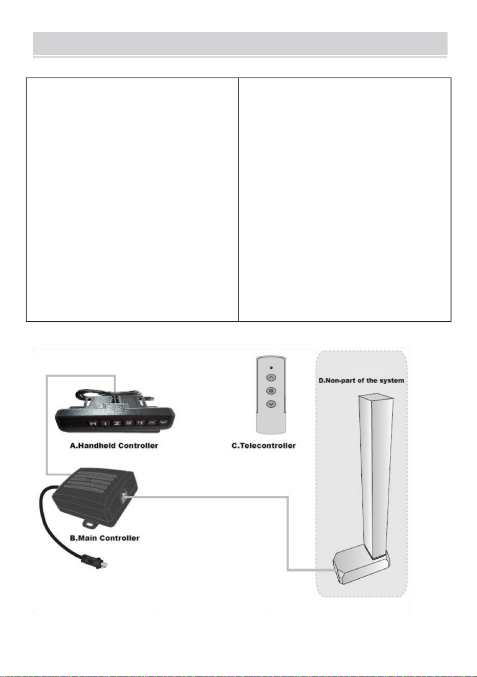
III. Systemanslutning
7
4. Maximal utström från motorgränssnittet: 4A;
4.Trådlös fjärrkontroll
(alternativ).
5. Driftstemperatur: 0 ~ 40 ÿ
Intelligent enkelkolumnstyrenhet har följande
egenskaper: 1. Den kan styra två motorers
utgång för att uppnå synkron drift; 2.
Indikatorlampa visar felet, återställer; 3.
Styrs av upp- och nedknappar; 3. Maximal utspänning från motorgränssnittet:
DC29V;
II. Systemparametrar
1.Ingångsspänning:DC29V;
2.Ingångsström: rekommenderas över
1,8A och beroende på belastningen;
I. Funktionsintroduktion
7. Förvaringstemperatur: 20 ~ 70 ÿ.
6. Arbetsfuktighet: 20~90%;
Instruktionsbok för kontrollenhet
Machine Translated by Google
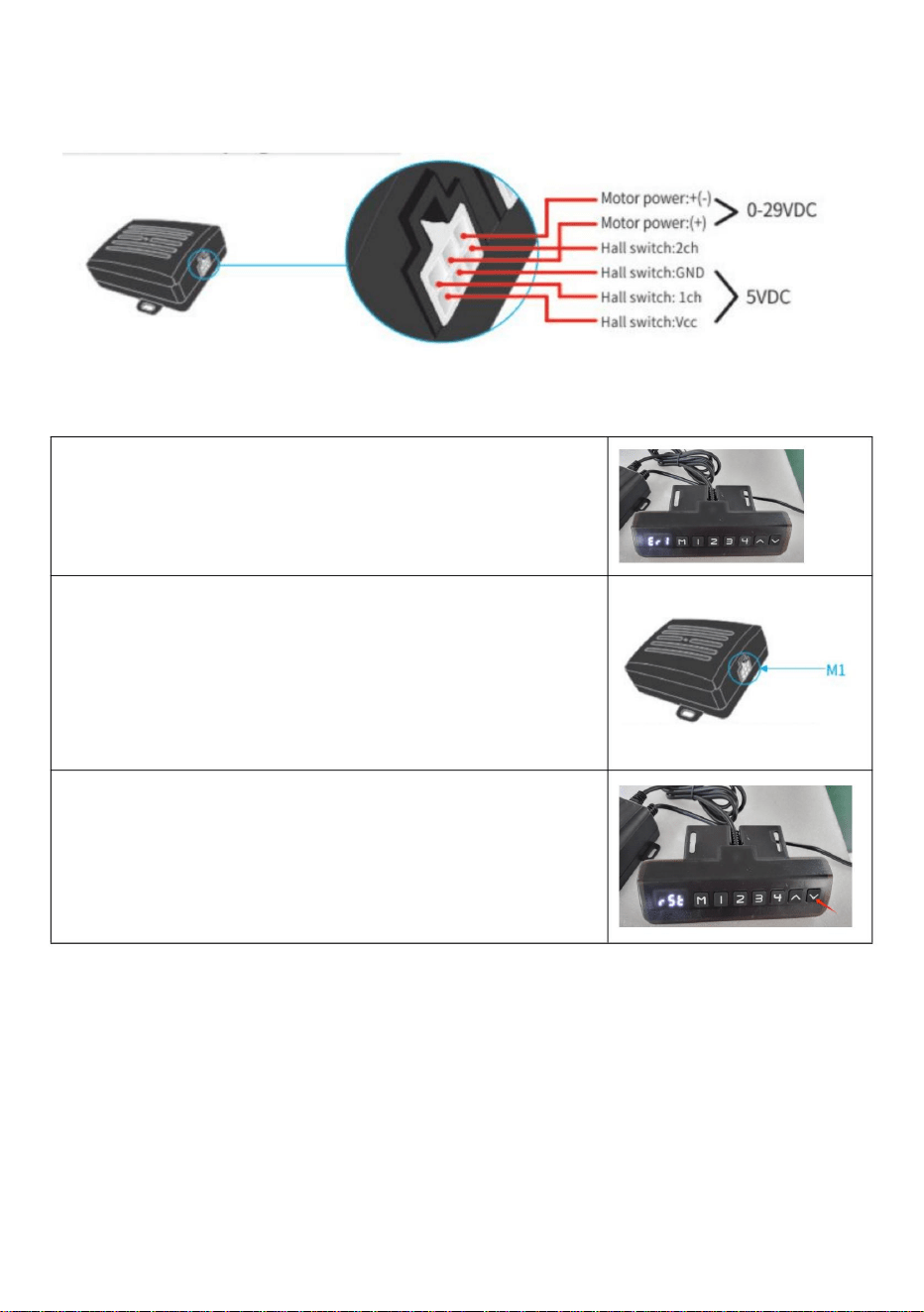
När problemet är löst, tryck på "ned"-knappen i mer än 3
sekunder för att åtgärda felet, och
När den manuella styrenheten visar Er1 är det ett fel på
Err1. Det betyder att det är något fel med M1-
gränssnittskanalen (se följande bild). F eller
exempelmotorer är inte anslutna på ett positivt sätt; Hall-
signalkortet är inte anslutet; Pappersledning, etc.
1.Felkod Err1
maskinen återgår till återställningsläge.
IV. Motorinterfaspluggdefinition:
V. Felkod och dess behandling
8
Machine Translated by Google

1.Prompt återställning
den manuella kontrollampan är tänd.
Släpp handen och börjar återställa systemet efter
och indikatorlampan lyser. Det betyder återställning.
andra skador under drift; om det finns några, sluta omedelbart.
höjd, tryck på ned-knappen i mer än 5 sekunder
När den manuella styrenheten visar minimum
Kolonnen kan börja bli kortare och hastigheten kan sakta ner. Observera för
2.Linjeåterställning
"-knappen" och släpp den inte.
förblir på (se följande bild), genom att trycka på "nedåt
återställer. Hela systemet måste återställas manuellt.
förblir på (se följande bild), betyder det att det är det
När den manuella styrenhetens indikator alltid lyser
3.Återställningsmetod
När den manuella styrenhetens indikator alltid lyser
VI. System reset
9
Machine Translated by Google

VII. Förinställd målhöjd
1.Förinställt antal målhöjd:
Systemet tillhandahåller 4 grupper av förinställd höjdlagring
2.Förinställd radering av målhöjdsdata:
Raderingsfunktionen är inte konfigurerad separat. När en ny parameter
punkt.
bild), släpp handen och avsluta vid återställning.
När den manuella styrenhetens indikatorlampa är släckt (se följande
Kolonnen kommer att stiga 5~10 mm efter en kort tid när den når som lägst
är inställd raderar systemet automatiskt den gamla parametern.
3.Förinställd målhöjd driftmetod:
aktuell höjdparameter kan förinställas till knapparna 1-4.
Exempel: ÿStäll in aktuell höjd 56 på knapp nr 2
På vilken höjd som helst (återställningstillstånd, kan inte utföra denna operation i feltillstånd),
ÿTryck på "M"-tangenten för att visa "SET"
10
Machine Translated by Google

ÿ. Backtracking när du stöter på hinder
ÿ. Användning av fjärrkontroll
5. Använd metoden för förinställd målhöjd: Vid
valfri höjd (återställningstillstånd, kan inte utföra denna operation i fel läge),
kan du använda knapparna 1-4 för att snabbt nå den förinställda målhöjden. Om
den aktuella höjden redan är nära den förinställda målhöjden kommer ingen
åtgärd att utföras.
1. Matchande fönsterperiod
Matchande fönsterperiod återaktiveras efter 3 sekunder. Det kommer att
höras ett surrande ljud när perioden slutar.
ÿFörinställningen "S-2" visas. Slut, föregående visning
återställs.
ÿInom 2 sekunder, tryck på "2" innan "SET" försvinner
2.Höger kod
Under matchande fönsterperiod, passerar ÿupp-knappenÿ länge och väntar på 4
långa och 3 korta intervaller av surrande ljud, betyder det att rätningskoden är över.
Utöver återställningstillståndet, när den arbetar, stöter den mekaniska
strukturen på plötsliga förändringar från belastningen, vilket kommer att få regulatorn
att utföra en reservoperation för att förhindra yttre ljud av skada.
11
Machine Translated by Google

Säker
DC29V
Amerika
1
Europa
Område
Input
2
Vikt
DT680-A 110lbs
50/60Hz
Belastning
100-240V~
Modell
1,8A
Adapterns
inspänning
PRODUKTPARAMETRAR
12
Machine Translated by Google

Machine Translated by Google