User Manual
X32 DIGITAL MIXER
40-Input, 25-Bus Digital Mixing Console with 32 Programmable
MIDAS Preamps, 25 Motorized Faders, Channel LCD’s,
32-Channel Audio Interface and iPad/iPhone Remote Control
VIEW
VIEW
VIEWVIEWVIEWVIEWVIEWVIEW
VIEW
VIEW
VIEW
–
5
5
0
–
10
10
–
20
–
30
–
40
–
50
–
60
–
00
–
5
5
0
–
10
10
–
20
–
30
–
40
–
50
–
60
–
00
–
5
5
0
–
10
10
–
20
–
30
–
40
–
50
–
60
–
00
–
6

2 X32 DIGITAL MIXER Preliminary User Manual
Table of Contents
Legal Disclaimer .............................................................3
Limited warranty ............................................................3
Introduction....................................................................4
1. Operational Overview ...............................................5
2. Callouts .....................................................................13
2.1 Channel Strip ......................................................................13
2.2 Input Channel Banks .......................................................14
2.3 Display and Monitoring..................................................15
2.4 Group/Bus Banks ..............................................................16
2.5 Scenes, Assign, Mute Groups .......................................17
2.6 Rear Panel Connections .................................................17
3. Hook-Up Diagrams ..................................................19
4. FX Descriptions ........................................................21
5. Topic Guide ..............................................................28
5.1 Starting up, shutting down,
and rmware updates .............................................................28
5.2 Default setup for connecting
to monitoring and P.A. systems ...........................................29
5.3 How do I connect a microphone,
process its signal and send it out
to the P.A. system? ....................................................................29
5.4 How do I add one of the 8 internal
eects to the sound? ...............................................................30
5.5 How do I use an outboard eectsprocessor? ........30
5.6 How do I set up live stage monitoring? ....................30
5.7 Everything you ought to know
about Solo and monitor sources.........................................31
5.8 Using Mute Groups ..........................................................32
5.9 Mix Buses, Sub Groups and DCA Groups .................32
5.10 User Assignable control section ................................ 32
5.11 How do I share signals over
AES50Supermac network? .................................................33
5.12 AES50 cabling requirements ......................................33
5.13 What kinds of Utilities are available? .......................33
5.14 How do I set up a Matrix for a delay
column/toweror a remote zone mix? ...............................34
5.15 Using the X32 in recording and production
studioenvironments ...............................................................35
5.16 Remote control ................................................................36
5.17 Recording a 2-track directly with theconsole ......36
5.18 Saving and recalling scenes ........................................36
5.19 Using the Real Time Analyzer (RTA) .........................36
6. USB Interface Operation Guide ..............................37
6.1 Conguring the X-USB card
for use in theconsole ..............................................................37
6.2 Conguring the PC to Interface
withtheX-USB Card ............................................................... 40
6.3 X-USB Specications........................................................42
7. X32 Main Display .....................................................43
7.1 Ove r vie w ..............................................................................43
7.2 Home Screen ..................................................................... 46
7.3 Meters Screen .....................................................................50
7.4 Routing Screen...................................................................51
7.5 Setup Screen ....................................................................... 55
7.6 Libraries Screen .................................................................58
7.7 Eects Screen .....................................................................59
7.8 Mute Group Screen ..........................................................59
7.9 Utility Screen .......................................................................60
7.10 Monitor/Talkback Screens: ..........................................60
7.11 USB Screen .........................................................................62
7.12 Assign Screen ..................................................................63
7.13 Scenes Screen ...................................................................65
8. Specications ...........................................................68
Block Diagram ..............................................................70
X32 MIDI Implementation ...........................................71
Dimensions ...................................................................73
3 X32 DIGITAL MIXER Preliminary User Manual
Important Safety
Instructions
LEGAL DISCLAIMER
LIMITED WARRANTY
Terminals marked with this symbol carry
electrical current of su cient magnitude
to constitute risk of electric shock.
Use only high-quality professional speaker cables with
¼" TS or twist-locking plugs pre-installed. Allother
installation or modi cation should be performed only
by quali edpersonnel.
This symbol, wherever it appears,
alertsyou to the presence of uninsulated
dangerous voltage inside the
enclosure-voltage that may be su cient to constitute a
risk ofshock.
This symbol, wherever it appears,
alertsyou to important operating and
maintenance instructions in the
accompanying literature. Please read the manual.
Caution
To reduce the risk of electric shock, donot
remove the top cover (or the rear section).
No user serviceable parts inside. Refer servicing to
quali ed personnel.
Caution
To reduce the risk of re or electric shock,
do not expose this appliance to rain and
moisture. The apparatus shall not be exposed to dripping
or splashing liquids and no objects lled with liquids,
suchas vases, shall be placed on the apparatus.
Caution
These service instructions are for use
by quali ed service personnel only.
Toreduce the risk of electric shock do not perform any
servicing other than that contained in the operation
instructions. Repairs have to be performed by quali ed
servicepersonnel.
1. Read these instructions.
2. Keep these instructions.
3. Heed all warnings.
4. Follow all instructions.
5. Do not use this apparatus near water.
6. Clean only with dry cloth.
7. Do not block any ventilation openings. Install in
accordance with the manufacturer’s instructions.
8. Do not install near any heat sources such as
radiators, heat registers, stoves, or other apparatus
(including ampli ers) that produce heat.
9. Do not defeat the safety purpose of the polarized
or grounding-type plug. A polarized plug has two blades
with one wider than the other. A grounding-type plug
has two blades and a third grounding prong. The wide
blade or the third prong are provided for your safety. Ifthe
provided plug does not t into your outlet, consult an
electrician for replacement of the obsolete outlet.
10. Protect the power cord from being walked on or
pinched particularly at plugs, convenience receptacles,
and the point where they exit from the apparatus.
11. Use only attachments/accessories speci ed by
themanufacturer.
12. Use only with the
cart, stand, tripod, bracket,
or table speci ed by the
manufacturer, orsold with
the apparatus. When a cart
is used, use caution when
moving the cart/apparatus
combination to avoid
injury from tip-over.
13. Unplug this apparatus during lightning storms or
when unused for long periods of time.
14. Refer all servicing to quali ed service personnel.
Servicing is required when the apparatus has been
damaged in any way, such as power supply cord or plug
is damaged, liquid has been spilled or objects have fallen
into the apparatus, the apparatus has been exposed
to rain or moisture, does not operate normally, or has
beendropped.
15. The apparatus shall be connected to a MAINS socket
outlet with a protective earthing connection.
16. Where the MAINS plug or an appliance coupler is
used as the disconnect device, the disconnect device shall
remain readily operable.
17. Correct disposal of this
product: This symbol indicates
that this product must not be
disposed of with household
waste, according to the WEEE
Directive (2012/19/EU) and
your national law. This product
should be taken to a collection center licensed for the
recycling of waste electrical and electronic equipment
(EEE). The mishandling of this type of waste could have
a possible negative impact on the environment and
human health due to potentially hazardous substances
that are generally associated with EEE. At the same time,
your cooperation in the correct disposal of this product
will contribute to the e cient use of natural resources.
For more information about where you can take your
waste equipment for recycling, please contact your local
city o ce, or your household waste collection service.
18. Do not install in a con ned space, such as a book
case or similar unit.
19. Do not place naked ame sources, such as lighted
candles, on the apparatus.
20. Please keep the environmental aspects of battery
disposal in mind. Batteries must be disposed-of at a
battery collection point.
21. Use this apparatus in tropical and/or
moderate climates.
MUSIC Group accepts no liability for any loss
which may be su ered by any person who relies
either wholly or in part upon any description,
photograph, or statement contained herein.
Technical speci cations, appearances and other
information are subject to change without notice.
All trademarks are the property of their respective
owners. MIDAS, KLARK TEKNIK, LAB GRUPPEN, LAKE,
TANNOY, TURBOSOUND, TC ELECTRONIC, TC HELICON,
BEHRINGER, BUGERA and DDA are trademarks
or registered trademarks of MUSIC Group IP Ltd.
© MUSIC Group IP Ltd. 2016 All rights reserved.
For the applicable warranty terms and conditions
and additional information regarding MUSIC Group’s
Limited Warranty, please see complete details online at
music-group.com/warranty.

4 X32 DIGITAL MIXER Preliminary User Manual
Introduction
Welcome to the X32 User Manual! After years of intense development, we are
proud to oer a mixer that combines tremendous power and exibility with a
very user-friendly layout and intuitive workow that allow you to get up-and-
running right away.
The X32 is the fully-integrated centerpiece of BEHRINGER’s digital mixing,
audio networking and processing ecosystem. It combines a control surface
with streamlined workow, extensive I/O and signal processing into a compact
desktop form factor. Employing motorized faders and rotary encoders along
with a daylight-viewable TFT screen, the control surface is designed to allow
immediate access to critical functions with total and automatic recall of settings.
Extensive on-board I/O includes 40 A/D and 24 D/A Cirrus Logic converters,
96bidirectional channels over SuperMAC AES50, stereo AES/EBU out, 16 channels
of BEHRINGER’s Ultranet personal monitoring and 32 x 32 channels for recording
over USB.
Abundantanalogconnectivity is provided via 32 MIDAS-designed digitally-
controllable microphone preamps, 6 line-level auxiliary in- and outputs, 16 XLR
outputs, stereo monitoring outs on XLR/TRS and dual phones outputs. Each of
the 32 microphone inputs can accept balanced or unbalanced mic or line-level
level signals and include switchable phantom power, 72 dB gain range and max
+23 dBu level before clip. A separate external mic input and the internal talkback
mic allow communication to various destinations.
Dual AES50 Ethernet jacks that employ KLARK TEKNIK SuperMAC technology
contribute 96 x 96 signals to the total count of 168 x 168 accessible sources and
destinations. Motorized faders, recallable mic preamps, programmable routing and
the ability to save and recall entire scenes make set or program changes quick and
simple. A top panel USB connector enables system data to be stored or a board mix
to be recorded directly to external ash or harddrives.
The Input section is home for 16 high-resolution 100 mm motorized faders,
providing control over channels 1-16, 17-32, Aux inputs / USB playback /
FXreturns. A separate section of 8 motorized faders controls DCA groups 1-8,
busmasters 1-8 and 9-16 as well as matrices 1-6.The master “X-channel”
sectionallows instant editing of the currently selected channel’s gain,
dynamics,EQ and other functions. A customassignablesection allows certain
control functions to be mapped directly toa set ofdedicated knobs and buttons.
A main 7"-wide, high-contrast color display provides information forediting
pertinent parameters of the active function or eect. Relevant parameters are
quickly recalled to the display for editing via “view” buttonsin each sub-section.
Each channel also features a small, customizable LCD screen for track name,
number,colorand source graphic.
A virtual FX rack oers 8 true-stereo (16 mono) multi-eects processors,
withover 60FX modelsthat eliminate the need for any additional outboard gear.
4high-quality eects such as delay, chorus and reverb can run concurrently with
8 channels of 31-band graphic equalization.
The built-in X-USB interface card enables streaming of up to 32 tracks to and from
a computer for recording, mixingandmastering purposes.
The X32 integrates seamlessly withother X32 consoles, the S16 digital stage box
and the P-16 personal monitoring system for complete live, studio and installed
sound solutions. Control the mixer from a distance with the free iPad app or with
editingand remote controlsoftware connected via Ethernet. The X32’seaseof
use, intuitiveworkow, diverse feature set and integration with other equipment
make it an ideal centerpiece for installedand productionsound in any setting.
Continue through this User Manual to learn all about the functionality
that this powerful mixer has to oer! We also recommend that you check
behringer.com tomake sure you have the latest rmware installed as we release
frequentupdates.
5 X32 DIGITAL MIXER Preliminary User Manual
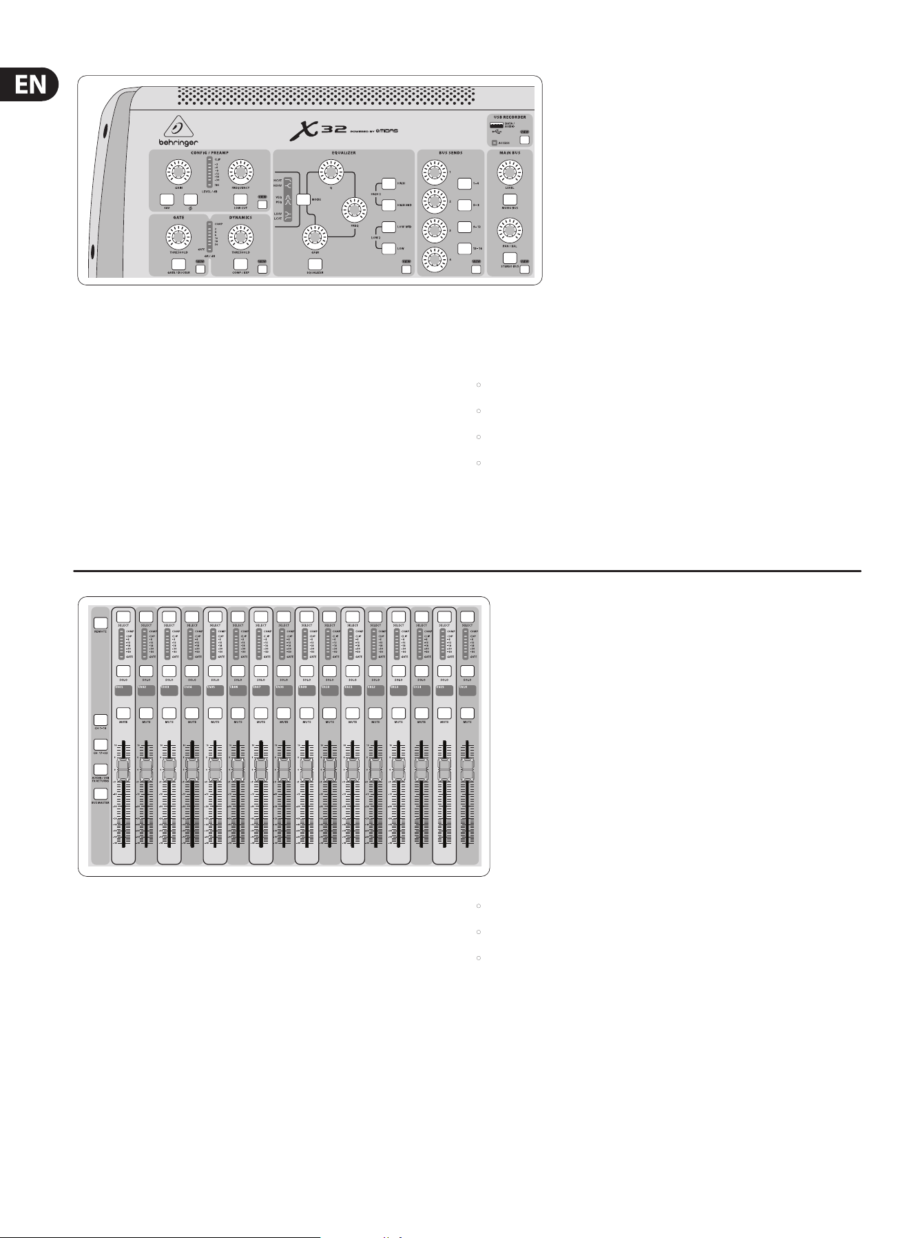
1. Operational Overview
VIEW
VIEW
VIEWVIEWVIEWVIEWVIEWVIEW
VIEW
VIEW
VIEW
–
5
5
0
–
10
10
–
20
–
30
–
40
–
50
–
60
–
00
–
5
5
0
–
10
10
–
20
–
30
–
40
–
50
–
60
–
00
–
5
5
0
–
10
10
–
20
–
30
–
40
–
50
–
60
–
00
–
6
(1) (3)
(4) (5)
(2 )
View buttons rule
Throughout the top panel of the console, youwillnd small buttons labeled
View. Press these buttons to immediately switch the console’s large color display
(known as the Main Display) to show information related to the section whose
View button you have just pressed.
For example, if you are editing the equalizer and feel like seeing a large display
of the EQ frequency response curve or corresponding EQ parametervalue,
simplypress the adjacent View button in the EQ section. If you need to check
where the talkback signal is being routed, simply press the View button next to
the Talk button and the main display will show the details.
With the View button approach of the X32 console, there is almost never a need
to drill down through multiple menu pages, since the View buttons will always
take you directly to the relevant screen.
Tip: The Setup/Global tab on the main display allows preferences for the behavior
of View and Select buttons to be adjusted.
Customizing the X32 through the Utilities page
Press the Utility button, located to the right of the main display, to bring up
useful functions in a “context-sensitive” manner. For example:
• When you are adjusting the equalizer of a console channel,
pressingtheUtility button will oer copying, pasting, loading or saving
ofequalizersettings
• Pressing the Utility button while editing a channel’s Preamp/Conguration
screen will present a naming screen where you can customize the channel’s
appearance on both the main display as well as the small channel display
• On the Routing pages, pressing the Utility button will oer loading or saving
dierent presets of routing scenarios
• In the Scenes menu, pressing the Utility button oers copying, loading,
saving or naming consolescenes
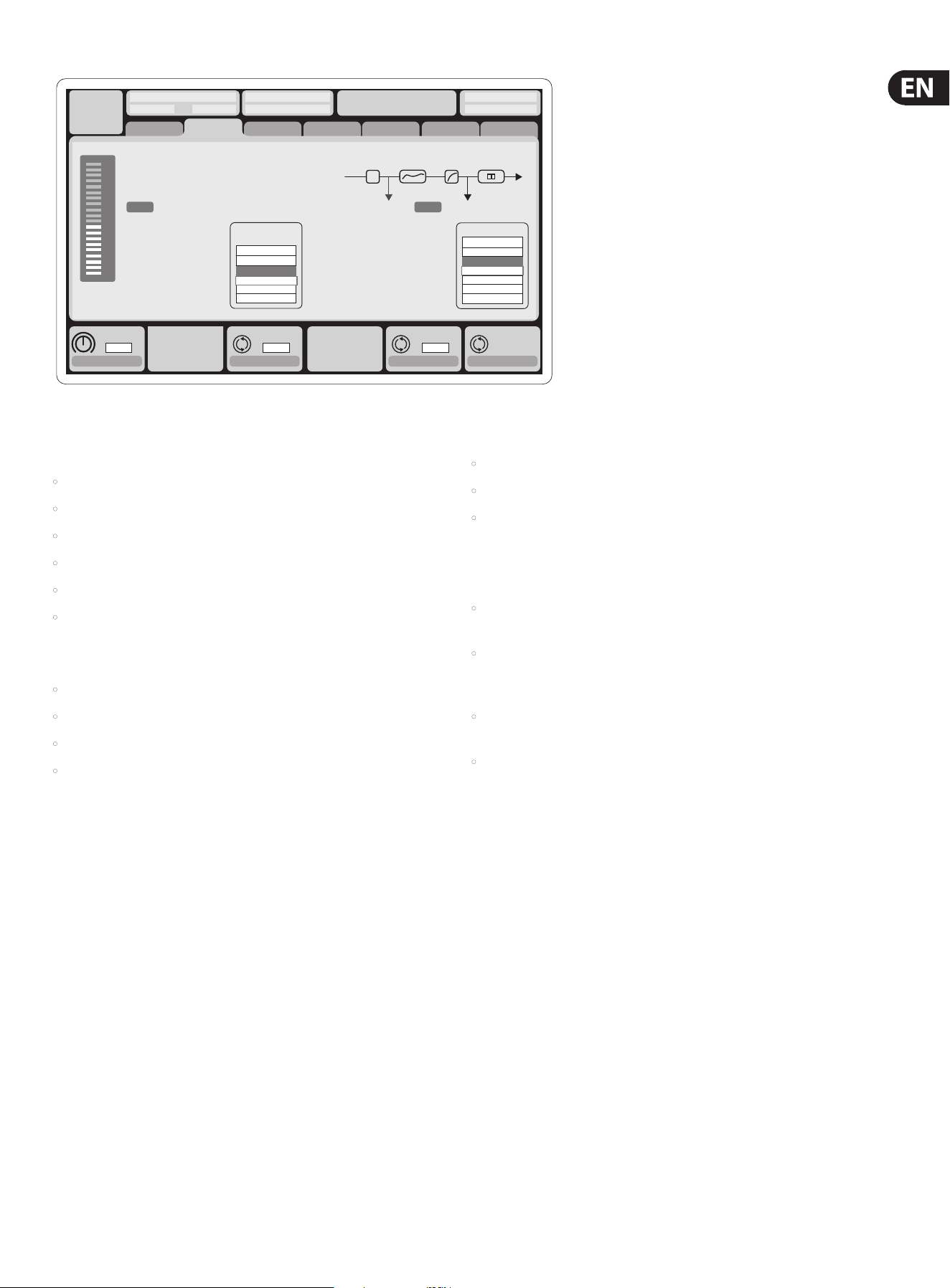
Sometimes there is more to say
Some of the individual pages on the main display contain
more adjustable parameters than can be controlled by
the 6 rotary push encoders located beneath it. In these
cases there is a small page number indication, e.g. “1/2”.
Simplypress the Layer Up/Down buttons to switch
betweenlayers.
Dir 05
Dir 06
Key In
Source
Select
1 2
Mixer Operational Overview
This chapter will give you an overview of the basic operations of the mixer,
allowing you to get up and running quickly. While reading through the
information, we encourage you to experiment with the console’s dierent
screens and controls. The console’s user interface was designed to be extremely
to navigate through and learn. Morespecic details about various functions can
be referenced later in the manual.
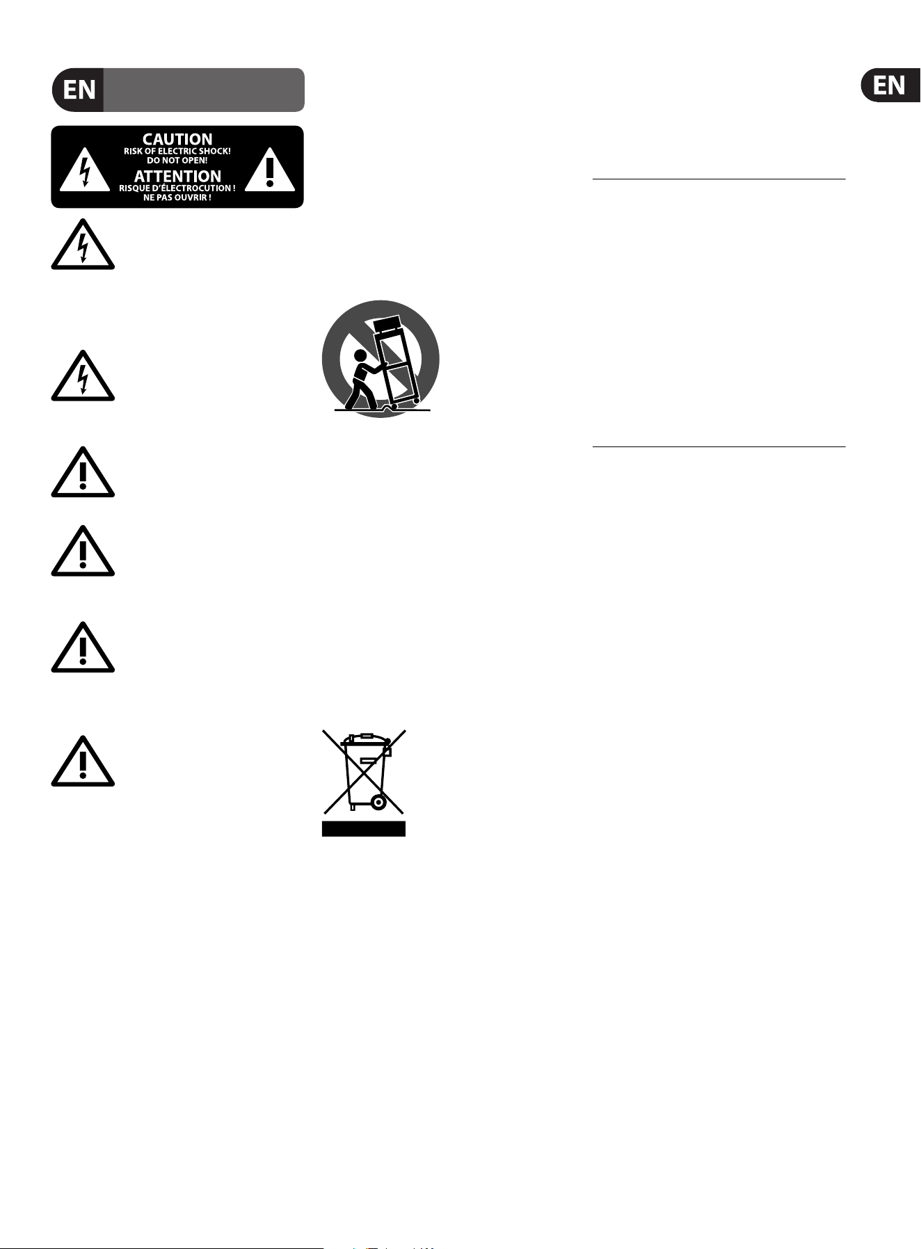
General user interface operation
The X32 user interface is divided into ve majorsections:
(1) Channel Strip
(2) Input Channels
(3) Display and Monitoring
(4) Group/Bus/Main Channels
(5) Scenes/Assign/Mute Groups
6 X32 DIGITAL MIXER Preliminary User Manual
–
5
5
0
–
10
10
–
20
–
30
–
40
–
50
–
60
–
00
–
5
5
0
–
10
10
–
20
–
30
–
40
–
50
–
60
–
00
–
5
5
0
–
10
10
–
20
–
30
–
40
–
50
–
60
–
00
Input Channel Banks
You will nd a select button on top of every channel that is used to direct the
control focus of the user interface, including all channel related parameters
(channel strip and main display), tothat channel. Please note that at any time,
there is exactly onechannel selected (either Input Ch 1-32, Aux1-8, FXReturns
1L-4R, Mix Bus 1-16, Main LR/C, orMatrix 1-6). DCA Groups (digitally controlled
amplier) cannot be selected because they control a number of assigned
channels rather than one specic channel.
The Input Channels section of the console is locatedon the left hand side, and
oers 16 separate input channel strips. These 16 channel strips represent three
separate layers of inputs for the console, including:
• Input Channels 1-16
• Input Channels 17-32
• Auxiliary Inputs 1-6/USB playback/FX Returns 1L-4R
Press any of the correspondingly labeled layer buttons on the left side of the
console to switch the input channel bank to any of the three layers listed above.
The button will illuminate, reminding you which layer is active.
A fourth layer (Bus Masters) is also oered, allowingyou to adjust the levels of
the 16 Mix Bus Masters, which is useful when you wish to include Bus Masters
into DCA Group assignments.
VIEWVIEWVIEWVIEW
VIEW
VIEW
VIEW
Channel Strip
The X32’s channel strip oers dedicated controls for the most important processing
parameters of the currently selected channel. To adjust controls for a given channel
strip, simply press the Select button on the desired input or outputchannel.
Certain sections of the channel strip (such as the low cut lter, noise gate, EQ and
compressor) contain a respectively labeled button that can be pressed to switch
the specic eect on and o. Thebutton illuminates to show the eect is active,
and goes dark when bypassed.
Within the channel strip, the rotary control knobs are surrounded by an amber
LED collar that indicates the parameter’s value. Whenever this backlit knob is
turned o, it indicates that this specic control/parameter is not available for
the selected channel type. For example, if an output bus is currently selected,
theLED collar and the gainknob are turned o, because there is no input gain to
be controlled on an output bus.
The channel strip consists of the following sub-sections:
• Cong/Preamp
• Gate, Dynamics
• Equalizer
• Bus Sends, Main Bus
Each of these subsections correspond to the processing steps of the currently
selected channel, and they each have their own View button that, when pressed,
switches the Main Display to a page displaying all related parameters for
thatsubsection.
7 X32 DIGITAL MIXER Preliminary User Manual
Ch01
FatSnare
OpeningScene
02: next 0:00 - 0:00
A: S16 A: 48K
B: - C: X-USB
: 15
01 15:33
home
cong
gate dyn eq sends main
Main Display Area
The main color display presents information about various sections of the
console. It can be switched to dierent screens using the console’s View buttons,
as well as any of the 8 buttons on the right side of the display.
The top section of the main display permanently covers useful status information.
The top left corner shows the selected channel number, its nickname and the
selected icon. The next block shows the current scene number and name in
amber, as well as the next upcoming scene. The center section displays the
playback le name along with elapsed and remaining time and a recorder status
icon. Thenext block to the right has 4 segments to show the status of AES50
ports A and B, the Card slot and the audio clock synchronization source and
sample rate (topright). Small green square indicators show proper connectivity.
The right most block shows the console time that can be set under Setup/Cong.
When working with any given screen, press the Page keys located on the display
bezel to switch to dierent screen pages.
Editing parameters or settings on each of the screens is done using the 6
associated push-encoders along the bottom edge of the display.
• Whenever there is a continuous control or list entry, you can turn the
corresponding knob forediting, which is indicated by various circularicons
• When there is a switch or toggle function on one of these knobs, you will see
a broad rectangular button along the lower edge of the eld. Pressing the
encoder changes the on/o state of the corresponding function. When the
rectangular button in the display is dark grey, thecorresponding function is
o/inactive; whenit is amber, the function is on/active
Monitoring and Talkback
There are two separate Level controls in this section, one for the headphone
outputs located on either side of the console, and a second one for the monitor
outputs located on the rear panel.
Press the section’s View button to edit various monitoring preferences, such as
the input source forthe phones bus and the monitor outputs.
This section also contains independent Talkback buttons (A and B). Press the View
button to edit the Talkback preferences for the Talkback A path and Talkback B
path separately. This screen also contains settings for the optional goose-neck
lamp and the console’s internal test-tone generator.
Group/Bus Channel Banks
This section of the console oers eight channel strips, divided into the
followinglayers:
• Eight DCA (digitally controlled amplier) groups
• Mix Bus masters 1-8
• Mix Bus masters 9-16
• Matrix Outputs 1-6, and the main center bus
This section also contains a main LR output fader, which is independent and
always available no matter which channel bank or layer is active.
When using the DCA Groups layer, the DCA Groups can be soloed and muted,
butthey cannot be selected. To edit the DCA group names, icons and colors,
navigate to the Setup/DCA Groups page on the main display.
When using any of the output bus layers, notethat the bottom LEDs on the
meters in this section illuminate when the respective bus is fed from pre-fader
sources of the selected channel.
VIEW
VIEW
–
6
On each fader strip you will nd a motorized 100mm level fader, Mute and Solo
buttons, aGate indicator, an input level meter, Compressorindicator, and the
channel selectbutton.
Each of the 16 input channels has an individual (andcustomizable) color LCD
screen that can display a channel number, nickname, and even a graphical
channel icon. In the event that a channel’s input source has been changed to an
input signal that diers from the default setup, the LCD displaywill also indicate
the name of the actual input source.
Ch01
Aux5
Soundcard
PC
Example: Channel 01 has the nickname Soundcard and is fed from Aux input 5.

8 X32 DIGITAL MIXER Preliminary User Manual
Various Assignments (DCA groups, mute groups,
custom assignable controls)
• Assigning DCA Groups
Thanks to the two distinct fader groups (inputs on the left, outputs on the right),
the task of assigning channels or buses to a virtual DCA Group is a breeze on the X32.
Simply hold the respective DCA Group Select button on the right-hand side of the
console, whilepressing the select buttons for all the input channels that you wish to
assign to said DCA Group. You can also press the DCA Group Select button in order
to check which channels are already assigned to it. Theassigned channel Select
buttons will light up.
• Assigning Mute Groups
The mute group assignment process is similar to the above, but is designed
with an additional precaution in order to prevent accidental muting of channels
during a show. To assign input/output channels to one of the six mute groups
(controlledby the buttons located to the right of the Main LR fader) you need
to rst switch on the Mute Grp button next to the main display. While holding
the desired Mute Group button, select the desired input and output channels,
whichwill now be assigned to the Mute Group. When you are done with
assignment, switcho Mute Grp at the display, andthe 6 Mute Group buttons
will work asintended.
• Custom Assignable Controls:
The Assign section of the console oers three banks: A, B, and C. Each set of
controls oers 4rotary controls and 8 switches/buttons, allowingfor freely
customizable access to 36random functions on the X32.
To make a custom assignment:
• Press the View button in the Assign section to edit the assignments
• Select the set of controls you wish to edit (A, B or C)
• Select the control 1-12 you wish to assign
• Select the parameter you wish to control and assign the function
Usually this is used to control a specic channel’s parameter, like the lead
vocalist’s reverb send level.
The Jump-to-Page control is a special target type that does not alter any
audio parameter, but rather brings you directly to any specied display page.
Buttonsthat had been used for Jump-to-Page previously can easily be reassigned
to the current display view by holding the respective set button (A, B or C)
depressed while pushing the desired assignable button. This method is more
convenient than reassigning the jump function through the Assign menu.
The “Sends on Faders” Function
The X32 console features a very useful function thatcan be accessed by pressing
the dedicated Sends on Faders button, located between the twofader sections.
The Sends on Faders function aids with level setting of channels sent to any of
the 16 Mix Buses. Itis only for channels assigned to Mix Buses 1-16, anddoes
NOT work for DCA groups, main or matrix buses. The Sends on Faders function
works in two convenient ways to cover the most obvious situations in a live
soundenvironment :
When preparing a monitor mix for a specicmusician
• Select the monitor bus (1-8, 9-16) that feeds the talent’s stage monitor
• Press the Sends on Faders button; itwillilluminate
• Select one of the three input channel layers (CH1-16, CH 17-32,
Line-Aux/FX Ret)
• As long as the Sends on Faders is active, allfaders in the input channels
section (locatedon the left side of the console) correspond to the send levels
to the selected (monitor) mix bus
When checking/editing where a selected input signal is
(to be) sent to
• Select the input channel in the left section
• Press the Sends on Faders button; itwillilluminate
• Select either bus channel layer 1-8 or 9-16
• The bus faders (located on right side of the console) now represent the
send levels from the selected input channel (located on the left side of
theconsole)
The option to use Sends on Faders in both ways, selecting an input or an output
channel, is a special feature of the X32.
Note - holding the Sends on Faders button for more than 1 second will engage
the function and cause the button to remain constantly lit rather than blinking.
VIEW
9 X32 DIGITAL MIXER Preliminary User Manual
Ch01
01:
0:00 - 0:00
A: S16 A: 48K
B: - C: X-USB
: 19
01
home
aux out
analog out
p16 out
card out aes50-a aes50-b
13:45
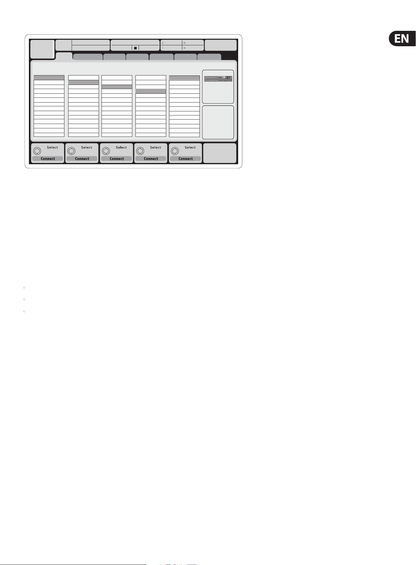
Inputs 1-8 Inputs 17-24Inputs 9-16
Channel Processing Block Patch
Inputs 25-32 Aux In 1-4
Connected Devices
Local In 1-8
Local In 9-16
[Local In 17-24]
[Local In 25-32]
AES50 A1-8
AES50 A9-16
AES50 A17-24
AES50 A25-32
AES50 A33-40
AES50 A41-48
AES50 B1-8
AES50 B9-16
AES50 B17-24
AES50 A25-32
Local In 1-8
Local In 9-16
[Local In 17-24]
[Local In 25-32]
AES50 A1-8
AES50 A9-16
AES50 A17-24
AES50 A25-32
AES50 A33-40
AES50 A41-48
AES50 B1-8
AES50 B9-16
AES50 B17-24
AES50 A25-32
Local In 1-8
Local In 9-16
[Local In 17-24]
[Local In 25-32]
AES50 A1-8
AES50 A9-16
AES50 A17-24
AES50 A25-32
AES50 A33-40
AES50 A41-48
AES50 B1-8
AES50 B9-16
AES50 B17-24
AES50 A25-32
Local In 1-8
Local In 9-16
[Local In 17-24]
[Local In 25-32]
AES50 A1-8
AES50 A9-16
AES50 A17-24
AES50 A25-32
AES50 A33-40
AES50 A41-48
AES50 B1-8
AES50 B9-16
AES50 B17-24
AES50 A25-32
Aux 1-4
Local 1-4
AES50 A1-4
AES50 B1-4
Card 1-4
AES50 A
AES50 B
Routing I/O
The X32 console features 32 analog rear-panel XLR inputs with microphone-
preamps, as well as 16rear-panel XLR Outputs and 6 TRS Aux Sends and Returns.
In addition, there are two AES50ports, eachfeaturing 48 input and output
channels, andacard slot for 32 channels of input and outputtoand from a
connected computer via USB2.0.
Input Signals can be attached to the console’s internal audio processing engine in
blocks of 8signals from any one of the aforementioned inputsources
Note: All signal blocks patched to the audio processing will be connected to the
corresponding input channels automatically.
Cabling for all AES50 connections between X32 and S16 stageboxes:
• Shielded Cat-5e cables only
• Ethercon terminated cable ends
• Maximum cable length 100 meters (330 feet)
10 X32 DIGITAL MIXER Preliminary User Manual
Link Lo Cut
Ch01
01:
01
0:00 - 0:00
A: S16 A: 48K
B: - C: X-USB
: 37
14:11
-6
-12
-18
-24
-30
-36
-42
-48
-54
clip
home gate dyn eq sends main
cong
Gain
Gain
48V
In
Pre PostIns
Delay
dB
+0.00
Link
Lo Cut
Lo Cut
Hz
20
Lo Cut
Input
Select
Source
PRE
Insert
Ins Pos
InsF
Connect
Insert
ms
0.3
Delay
Delay
Delay
dB
+0.0
Hz
2.0
Reverse
t
ft
m
ms
0.3
0.10
0.03
Source
OFF
Input 01
Input 02
Input 03
Input 04
Input 05
Input 06
Insert
OFF
InsFX 1L
InsFX 1R
InsFX 2L
InsFX 2R
InsFX 3L
InsFX 3L
Insert Position
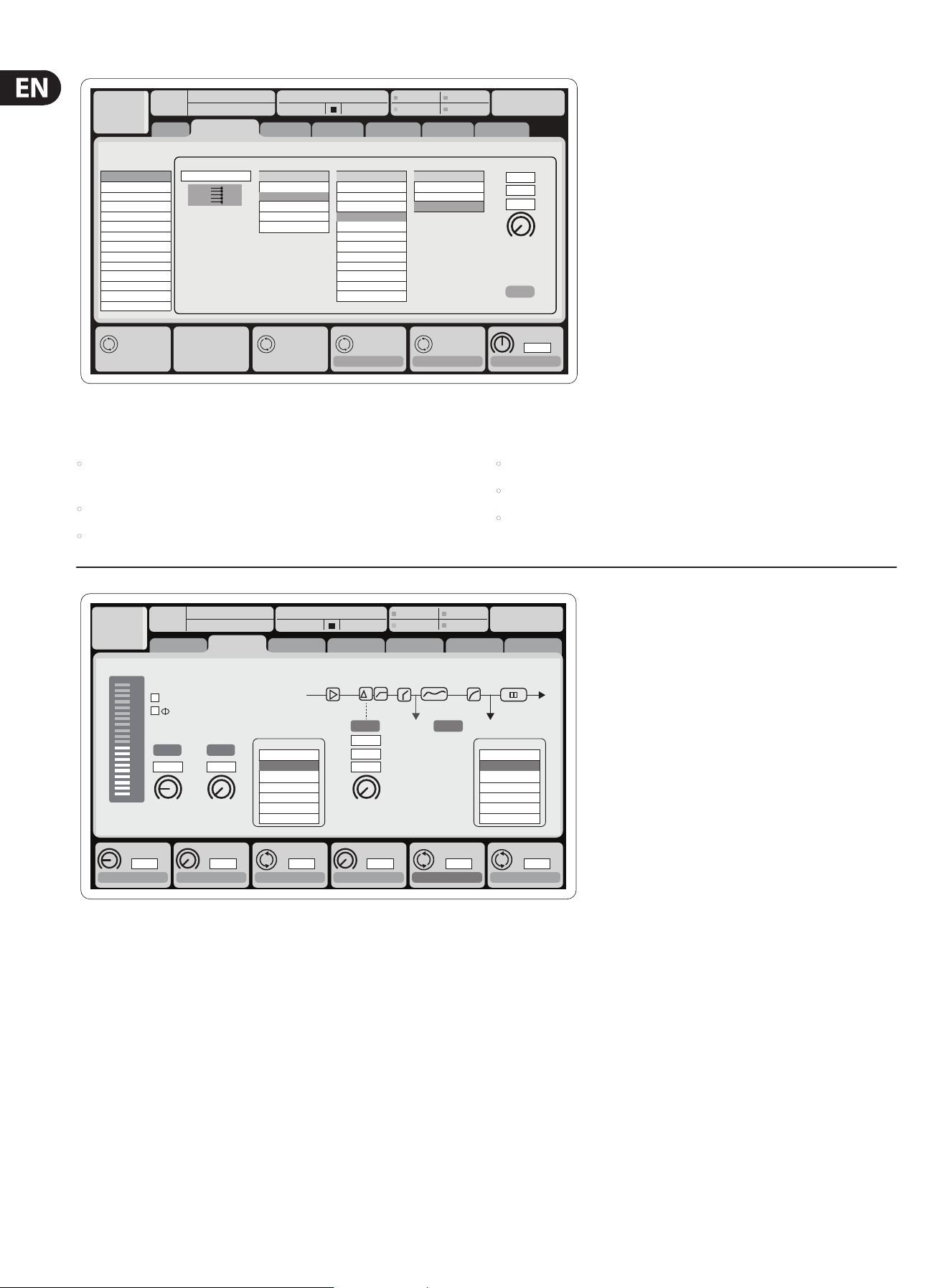
Input Channels 1-32 are pre-congured to use the rst 32 input signals,
butcan be patched to use any other available signal on the audio engine as well,
including mix bus/sub group outputs. Changes of the Channel Source can be
made on the Preamp Congpage.
Aux Return Channels 1-8 are pre-congured to use the 6 aux input signals,
andthe two USB playback outputs, but can be patched to use any other available
signal of the console as well.
FX Return Channels 1L-4R control the 4 stereo output signals of side-chainFX1-4.
Delay
ms
0.3
Set DelayAssign
ft
m
ms
0.3
0.3
0.10
Delay
Delay
Select Select Select Select
Ch01
01:
01
home aux out
analog out
p16 out
card out aes50-a aes50-b
Analog Output
CategoryCurrent Setting
Edit Output Assignment
Processed Output Signal Tap
0:00 - 0:00
A: S16 A: 48K
B: - C: X-USB
: 37
14:09
Output 01
Output 02
Output 03
Output 04
Output 05
Output 06
Output 07
Output 08
*Output 09
*Output 10
*Output 11
*Output 12
*Output 13
*Output 14
MixBus
OFF
Main (LRC)
Mix Bus
Matrix
Direct Out
Monitor
OFF
Main L
Main R
Main C/M
Main Bus 01
Main Bus 02
Main Bus 03
Main Bus 04
Main Bus 05
Main Bus 06
Main Bus 07
Main Bus 08
Main Bus 09
Pre EQ
Post EQ
Pre Fader
Post Fader
Output Signals can be freely assigned from anyinternal signal to any of the
following outputs:
• 16x analog local XLR outputs (with adjustable digital delay for
time-alignment of speakers)
• 6x auxiliary sends on ¼" TRS outputs + 2x AES/EBU outputs
• 16x personal monitoring using the console’s P-16 Bus output connector
Any and all of the above signals can also be mirrored in blocks of 8 signals on
either one of
• 48x channels on AES50 port A
• 48x channels on AES50 port B
• 32x channels on X-USB interface card
11 X32 DIGITAL MIXER Preliminary User Manual
Inputs
-6
-12
-18
-24
-30
-36
-42
-48
-54
clip
Link
Gain
dB
00.00
Send Pos. Insert Pos. Insert
Link Bus Sends
Insert
Connect
Pre
LeOnde.mp3
29 November 2010 Scene01
13:44:43 MyProj.prj
00.05.00 00.00.00
home gate dyn eq sends main
cong
Bus Conguration Bus Insert Position
Insert
Ins 02
FX 01
FX 02
Ins 01
...
Ins 03
Ins 04
All Channel Sends
Pre Conguration
Inputs
Sub Grou
...
Post Fader
Pre EQ
Pre Fader
Insert PostPre
∑
Channel Sends
The conguration of Mix Bus Channels 1-16 can be pre-set (in the Setup/Global
page) or can also be congured on an individual, per-channel basis. Thebus
processing includes (in this order):
• Insert point (swappable between post-EQ and pre-EQ operation)
• 6-band fully parametric EQ
• Compressor/expander (swappable between post-EQ and pre-EQ operation)
• Bus sends to 6 matrices
• Main LR panning
• Mono/Center level
Main Bus Channels LR/C are always available and independent from Mix Buses.
The processing steps for this signal path include (in this order):
• Insert point (swappable between post-EQ and pre-EQ operation)
• 6-band fully parametric EQ
• Compressor/expander (swappable between post-EQ and pre-EQ operation)
• Bus sends to 6 matrices
Matrix Channels 1-6 are fed exclusively by MAINLRC and Mix Bus 1-16 signals.
The processing steps include (in this order):
• Insert point (swappable between post-EQ and pre-EQ operation)
• 6-band fully parametric EQ
• Compressor/expander (swappable between post-EQ and pre-EQ operation)
Eects Processing 1-8
The X32 console contains eight true-stereo internal eects engines.
• FX 1-4 can be congured as side chain or insert eects, while FX 5-8 can only
be used in insert points of channels or buses
• The returns of side chain FX 1-4 can always be controlled using the 3rd bank
(layer) of the input channels - Aux/USB/FX Returns. Note that the return
signals of FX 1-4 have separate faders for left and right
• The FX Home screen allows selection of the FX 1-4 input sources and selecting
the eects type/algorithm for each of the 8 FX slots of the virtualrack
• The subsequent tabs FX 1-FX 8 of the FX screen allow editing all parameters
of the chosen eects processor

12 X32 DIGITAL MIXER Preliminary User Manual
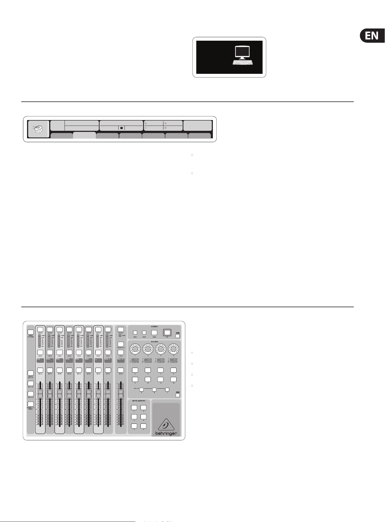
X32 iPad App
Many functions of the X32 console can be remotely controlled by a dedicated
iPad app. Details about the app’s download, setup and operation are available on
the X32 product page.
The app’s User Interface is optimized for the touchscreen nature of the iPad and
concentrates on the most important remote features of the console. Using the
app, you can perform functions such as adjusting monitor mixes from the stage
while interacting with musicians, or adjusting the front-of-house mix from the
audience, while hearing the mix exactly as the audience does.
X32 Windows/OS X/Linux Application
Also oered is a separate remote editor running on host computers that will
allow for complete editing control of the X32 via Ethernet. Check out behringer.
com for more information.
Tip: The X32 remote communication is OSC-based (open sound control) and we
will share the protocol on our website, allowing developers to design their own
control software. Stay tuned to behringer.com for details on the OSC protocol.
X-USB expansion card
The X-USB card allows transmission of up to 32 channels to and from a connected
computer. Please download the X-USB drivers and Quick Start Guide from
behringer.com before connecting the mixer to your computer.
Note - the rst X32 production units shipped with the X-UF FireWire/USB card.
See the “USB Interface Operation Guide” for details.
Startup and Shutdown, and Update:
We recommend switching the X32 mixer on rst, and shutting it o last
when any sound system is connected. This will prevent the possibility of any
unexpected noises being transmitted during the startup/shutdown process.
The Setup screen’s general preference page contains a Safe Main Levels
function. When activated, the console automatically mutes the main LRC levels
when booting the console. It also prevents any scene loading from aecting
(i.e. turning up) the mains levels.
Synchronization and Sample Rate settings for the console can be adjusted on
the Setup/Cong page, but please note that sample rate changes will require a
reboot of the console. When you see a red square indication at the top section of
the main display, please verify if the synchronization settings on Setup/Cong
make sense (see section 3).
If the console has been used by someone else, and you feel unsure about its specic
routing status, you can reset the X32 to default settings in two convenient ways:
• While the console is booting and the “X32” logo appears on the screen,
press and hold the Scenes/Undo button until the console is fully operational
and the Home screen is displayed. The console will now be in the same state
as it was when shipped from the factory. However, you can immediately
revert to the status the console was in when being switched o the last time
by pressing the Scenes/Undo button
• You can also reset the console any time after booting by pressing
Setup/Cong, then Initialize
NOTE: Initializing the console does not automatically erase the current show data
or any stored scenes. If you wish to clear all scenes, please use the ’Initialize All
Show Data’ option on Setup/Cong page.
In order to prevent any errors by losing power during a store operation,
we recommend using the “Safe Shutdown” function from the Setup/Global page.
NOTE: The X32 can be locked against unintended use by activating ’Lock Console’
from the Setup/Global page. In this state the UI will not allow any changes to be
made and the display shows “X”. Keep HOME depressed for about 5 seconds to
unlock the X32 again.
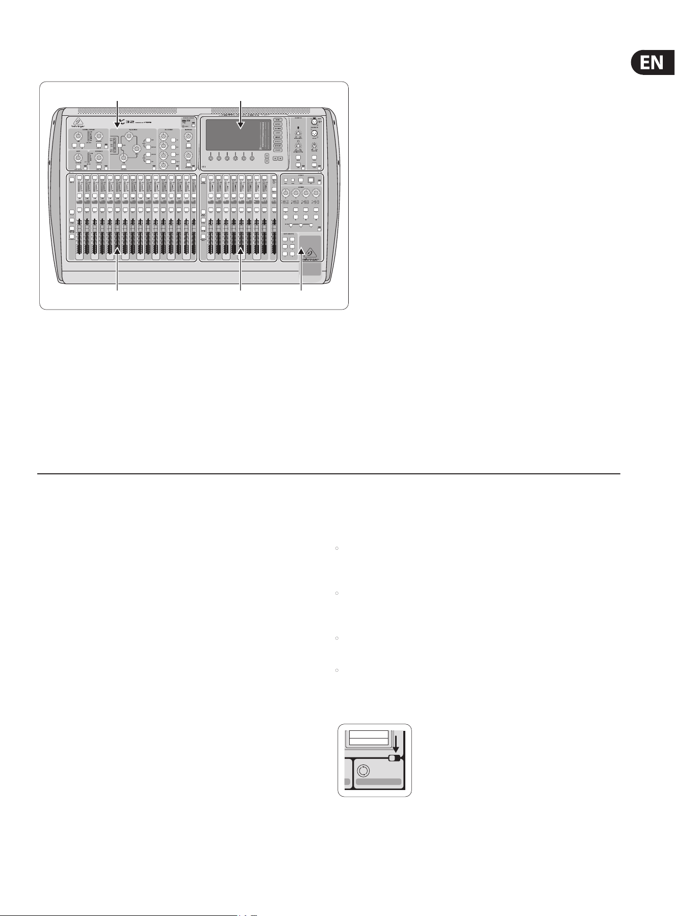
The X32 rmware can easily be updated by performing the following steps:
• Download the new console rmware from the X32 product page onto the
root level of a USB thumb drive
• Plug the USB thumb drive into the top panel USB connector while the
console is turned o
• Hold the USB View button depressed while switching the console on.
While booting, the X32 will run a fully automatic rmware update,
which will take 2-3 minutes longer than the regular boot sequence
When no update le is available on the USB drive, or when it is corrupted,
the update mode will remain active, preventing the X32 from booting regularly.
Switch the console o and back on without holding the USB View button to boot
the console with the existing rmware.
CAUTION: Please do not block the fan opening on the bottom of the X32
cabinet! The large slow-turning fan is barely audible, but it is still working.
Specically when mounting the X32 in a road case, please ensure there is
sucient space underneath to allow for some airow.
13 X32 DIGITAL MIXER Preliminary User Manual
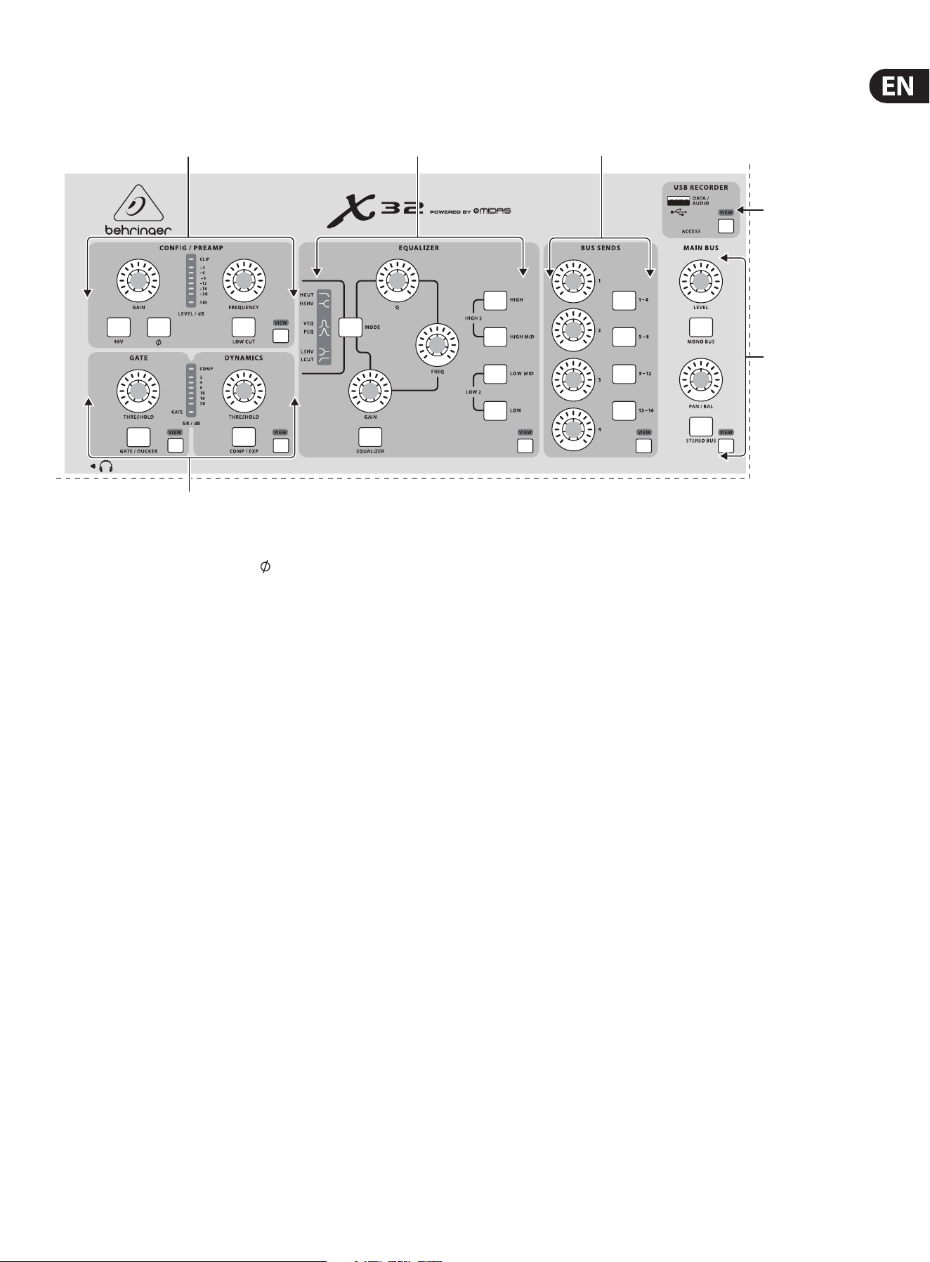
2. Callouts
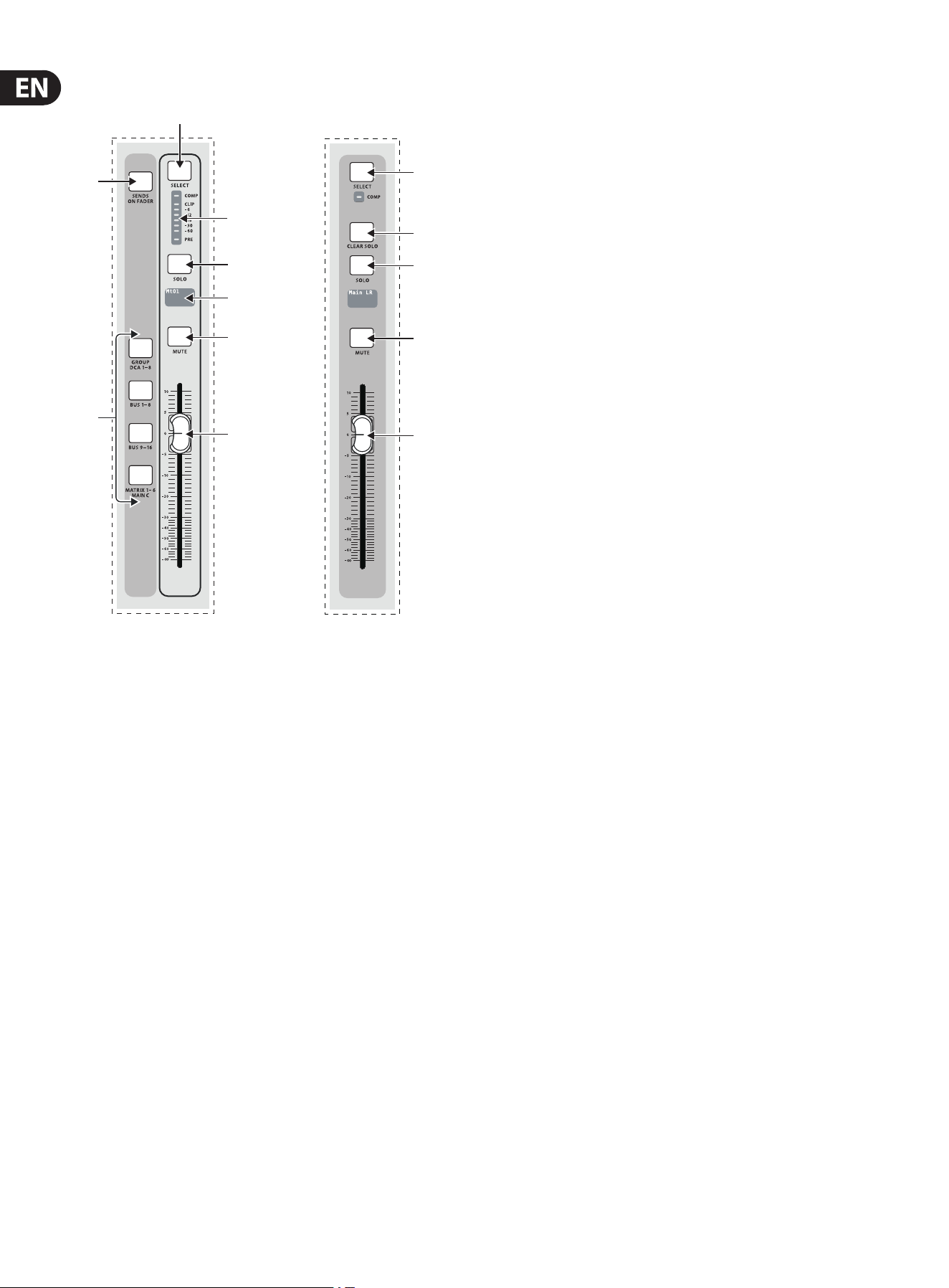
2.1 Channel Strip
VIEWVIEWVIEWVIEW
VIEW
VIEW
VIEW
(3)
(6)
(4)
(2)
(5)
(1)
(1) Preamp – Adjust the preamp gain for the selected channel with the
Gainknob. Press the 48 V button to apply phantom power for use with
condenser microphones and press the button to reverse the channel’s
phase. The meter displays the selected channel’s level. Press the Low Cut
button and select the desired high-pass frequency to remove unwanted
lows. Press the View button to access more detailed parameters on the
MainDisplay. Note - It is best practice to mute the respective channels prior
to switching their phantom power supply on or o. Otherwise, the change
of charge may cause an audible popping noise. Gain adjustments might
also produce audible click noise when adjust shortly after having switched
phantom power on or o.
(2) Gate/Dynamics – Press the Gate/Ducker button to engage the noise gate
and adjust the threshold accordingly. Press the Comp/Exp button to engage
the compressor and adjust the threshold accordingly. When the signal level
in the meter drops below the selected Gate threshold, the noise gate will
silence the channel. When the signal level reaches the selected Dynamics
threshold, the peaks will be compressed. Press the View buttons to access
more parameters on the Main Display.
(3) Equalizer – Press the Equalizer button to engage this section. Selectone
of the 4 frequency bands with the High, High Mid, Low Mid, and Low knobs.
Press the Mode button to cycle through the types of EQ available. Selectthe
specic frequency to be adjusted with the Freq knob, andadjust the bandwidth
of the EQ with the Q knob. Finally, boost or cut the selected frequency with the
Gain knob. Press the View button for more editingoptions.
(4) Bus Sends – Quickly adjust the bus sends by selecting one of the 4 banks,
followed by one of the 4 knobs. Press the View button for more detailed
editing and routing.
(5) USB Recorder – Connect a thumb drive to install rmware updates and to
record performances. See the Topic Guide section for details.
(6) Main Bus – Press the Mono Bus or Stereo Bus to assign the channel to the
main mono or stereo bus. When Stereo Bus is selected, the Pan/Bal adjusts
the left-to-right positioning. Adjust the overall send level to the Mono Bus
with the Level knob. Press the View button for more editing options.
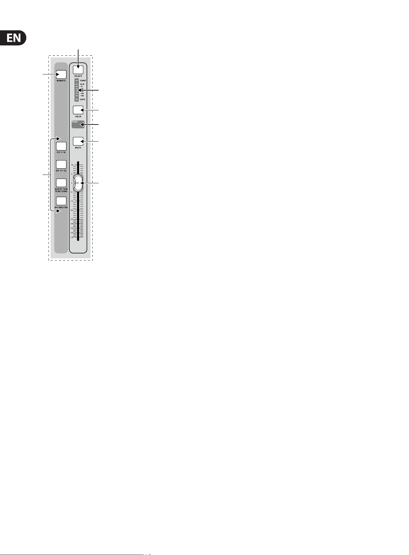
14 X32 DIGITAL MIXER Preliminary User Manual
2.2 Input Channel Banks (7) Layer Select – Select either the channels 1-16, channels 17-32,
Aux In/USB/FX Returns, or Bus Masters layer with these 4 buttons.
Thecurrently active layer will light.
(8) DAW Remote – Press this to enable DAW remote control.
(9) Select – Press this button to select an input or bus (depending which layer
is active) and allow it to be edited by the Channel Strip and Main Display.
(10) Channel Meter – This displays the signal level of the input or bus
(depending which layer is active). The Gate and Comp LEDs light to indicate
that noise gate and/or compression are active.
(11) Solo – Press this button to send the channel to the Solo Bus.
(12) Mini Display – Information such as channel number,
nickname,inputsource and graphical icon are displayed on this
colorLCDscreen.
(13) Mute – Press this button to mute the channel.
(14) Fader – Use this to adjust the channel volume or bus send in ’Sends on
Faders’ mode. The faders will automatically display the current status as
layers and functions are changed.
(9)
(8)
(10)
(11)
(12)
(13)
(14)
(7)
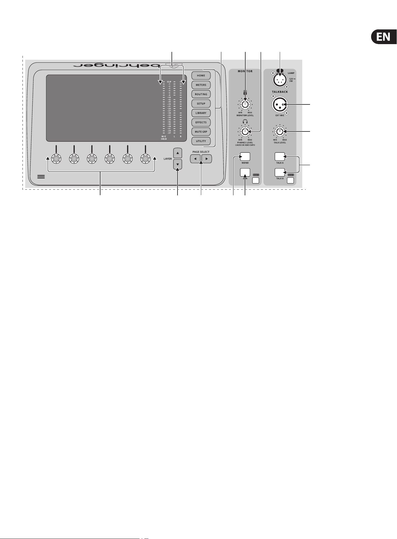
15 X32 DIGITAL MIXER Preliminary User Manual
2.3 Display and Monitoring
VIEWVIEW
(16) (23)
(20)
(26)
(25)
(17) (22)
(27)
(21)(19)(18)
(15)
(24)
(15) Push Encoders – These 6 controls adjust the parameters presented at the
bottom of the Main Display. The editable function will show a circular icon
in the display when continuous control is available. The function will show a
broad rectangular icon to indicate that a switch or toggle can be accessed by
pushing the encoder.
(16) Layer Buttons – Some screens in the Main Display have more than
6editable parameters which can be accessed by pressing the Layer Up or
Down buttons.
(17) Page Select Buttons – Use these to scroll through the available screens or
to conrm/decline certain actions.
(18) Main/Solo Meters – The main stereo output level is displayed here along
with the solo level of all channels whose Solo button is active.
(19) Category Select Buttons – Press one of these buttons to jump directly to
the subject you wish to edit or congure.
(20) Monitor Level – Adjust the level of the Monitor outputs with this knob.
(21) Phones Level – Adjust the volume of the headphone outputs,
locatedinside the left and right side caps.
(22) Monitor Mono – Press this button to monitor the audio in mono.
(23) Dim – Press this button to reduce the monitor volume. Press the
View button to adjust the amount of attenuation along with all other
monitoring-related functions.
(24) Lamp Input – Connect a standard 12 V, 5 Watt gooseneck lamp here.
(25) Talkback Input – Connect a talkback mic via standard XLR cable to
thisinput.
(26) Talk Level – Adjust the level of the talkback mic with this knob.
(27) Talk A/B – Select the destination for the talkback mic signal with these
buttons. Press the View button to edit the talkback routing for A and B.
16 X32 DIGITAL MIXER Preliminary User Manual
2.4 Group/Bus Banks (28) Group/Bus Layers – Select between DCA groups 1-8, Buses 1-8 or 9-16,
or Matrices 1-6 and the main center bus with these buttons. The currently
active layer will light.
(29) Sends on Faders – Press this button to activate the Sends on Faders
function. See the Topic Guide for more details.
(30) Select – Press this button to select a DCA or bus (depending which layer
isactive) and allow it to be edited by the Channel Strip and Main Display.
(31) Group/Bus Meter – This displays the signal level of the DCA or bus
(depending which layer is active). The Pre LED indicates that the bus is
sourced pre-fader, while the Comp LED indicates that compression is active.
(32) Solo – Press this button to solo the DCA or bus.
(33) Mini Display – Information such as matrix/bus number,
nickname, input source and graphical icon are displayed on this color
LCDscribble strip screen.
(34) Mute – Press this button to mute the DCA or bus.
(35) Fader – Use this to adjust the bus level. The faders will automatically display
the current status as layers and functions are changed.
(36) Main Select – Press this button to select the main bus for editing.
(37) Clear Solo – Press this button to release all sources assigned to the solobus.
(38) Main Solo – Press this button to solo the main bus.
(39) Main Mute – Press this button to mute the main bus.
(40) Main Fader – This fader adjusts the output of the main bus.
(30)
(29)
(31)
(36)
(37)
(38)
(39)
(40)
(32)
(33)
(34)
(35)
(28)
17 X32 DIGITAL MIXER Preliminary User Manual
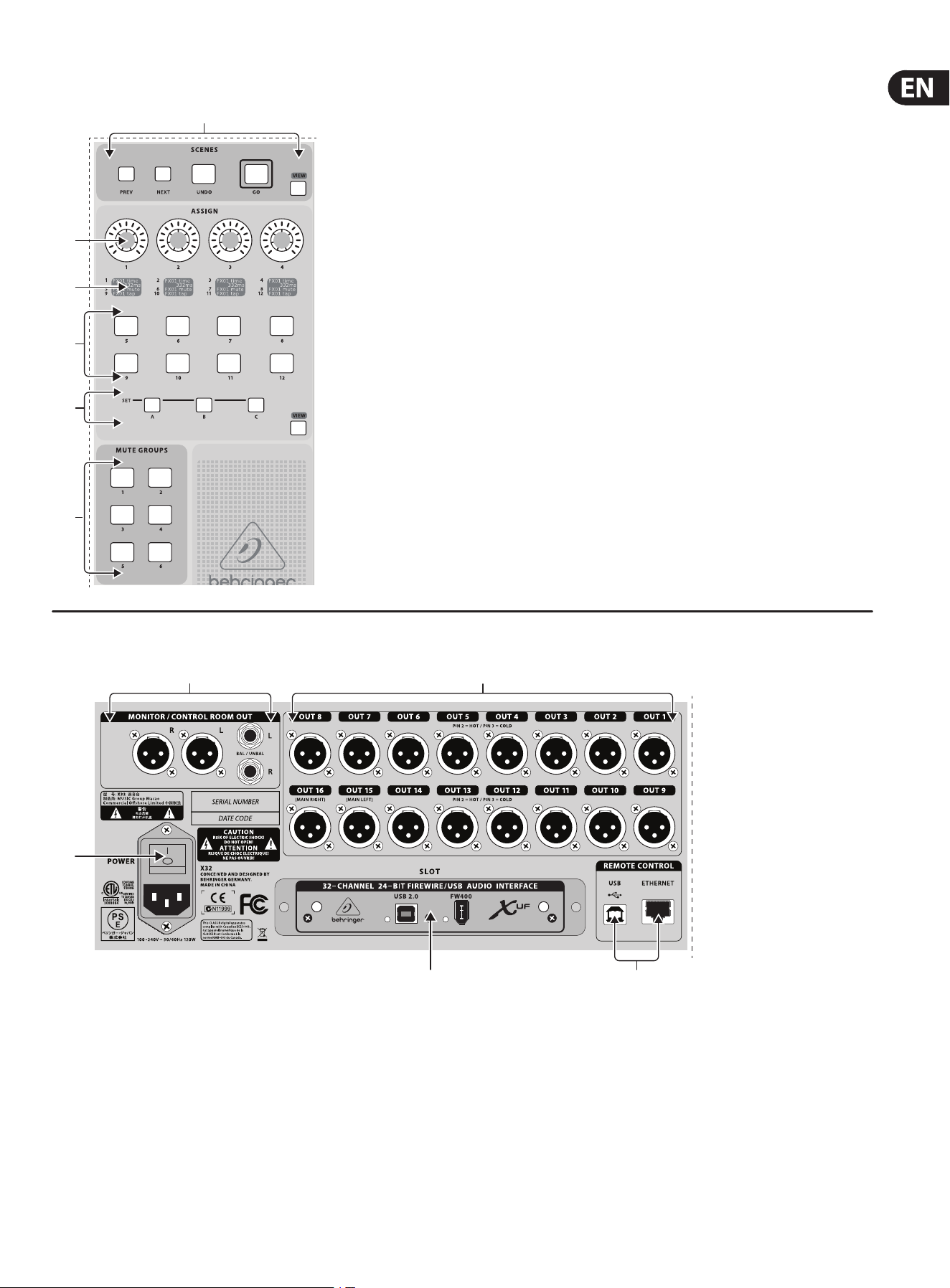
2.5 Scenes, Assign, Mute Groups (41) Mute Groups – Press one of these buttons to activate one of the mute
groups. See the Topic Guide for details.
(42) Set Select Buttons – Press one of these buttons to activate one of the
3layers of custom assignable controls.
(43) Custom Assign Buttons – Assign these 8 buttons to various parameters
for instant access to commonly used functions. See the TopicGuide
fordetails.
(44) Assign Displays – These displays provide quick reference to the
assignments of the active layer of custom controls.
(45) Custom Assign Knobs – Assign these 4 knobs to various parameters for
instant access to commonly used functions. See the Topic Guide for details.
(46) Scenes Buttons – Use these buttons select and activate saved scenes.
Seethe Topic Guide for details.
VIEW
VIEW
(45)
(44)
(43)
(42)
(41)
(46)
2.6 Rear Panel Connections
(50) (51)
(49)
(56)
(52) (53) (54) (55)
(47) (48)
(57)
(47) Monitor / Control Room Outputs – Connect a pair of studio monitors
using XLR or ¼" cables.
(48) Outputs 1-16 – Send audio to external equipment using XLR cables.
Outputs 15 and 16, by default, carry the main stereo bus signals.
(49) Power Switch – Turn the power on and o with this switch.
(50) X-USB card – Transmit up to 32 channels of audio to and from a
computer via USB 2.0.
(51) Remote Control – Connect to a PC for remote control via USB or
Ethernetcable.
18 X32 DIGITAL MIXER Preliminary User Manual
(50) (51)
(49)
(56)
(52) (53) (54) (55)
(47) (48)
(57)
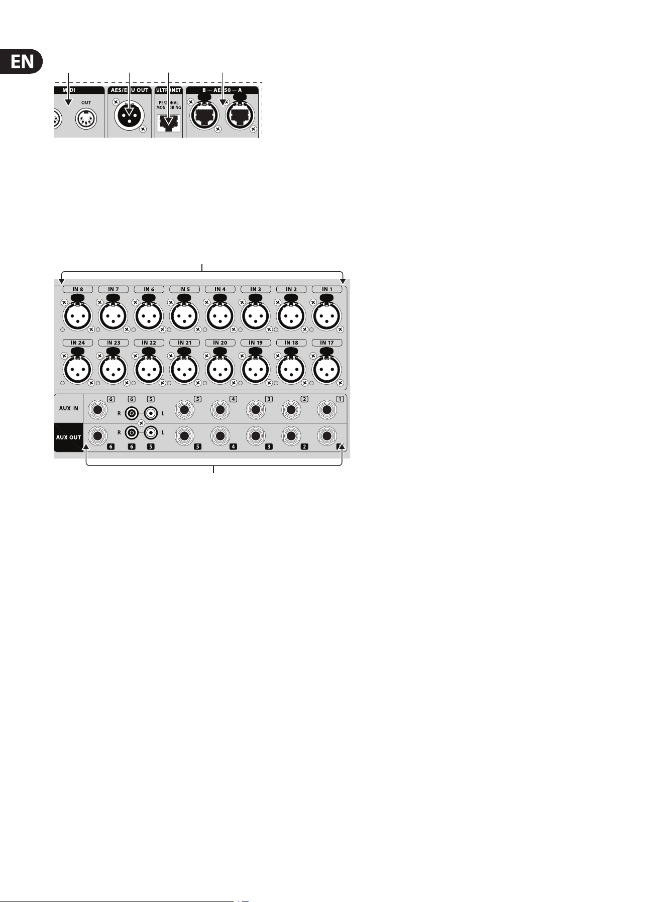
(52) MIDI In/Out – Send and receive MIDI commands via 5-pin DIN cables.
(53) AES/EBU Out – Send digital audio via 3-pin AES/EBU XLR cable.
(54) Ultranet – Connect to a BEHRINGER P-16 personal monitoring system via
Ethernet cable.
(55) AES50 A/B – Transmit up to 96 channels in and out via shielded
CAT-5e cables.
(56) Inputs 1-32 – Connect audio sources via XLR cables.
(57) AUX IN/OUT – Connect to and from external equipment via
¼"orRCAcables.
(50) (51)
(49)
(56)
(52) (53) (54) (55)
(47) (48)
(57)
19 X32 DIGITAL MIXER Preliminary User Manual
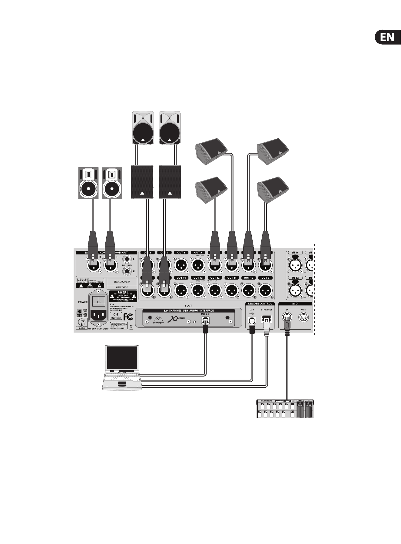
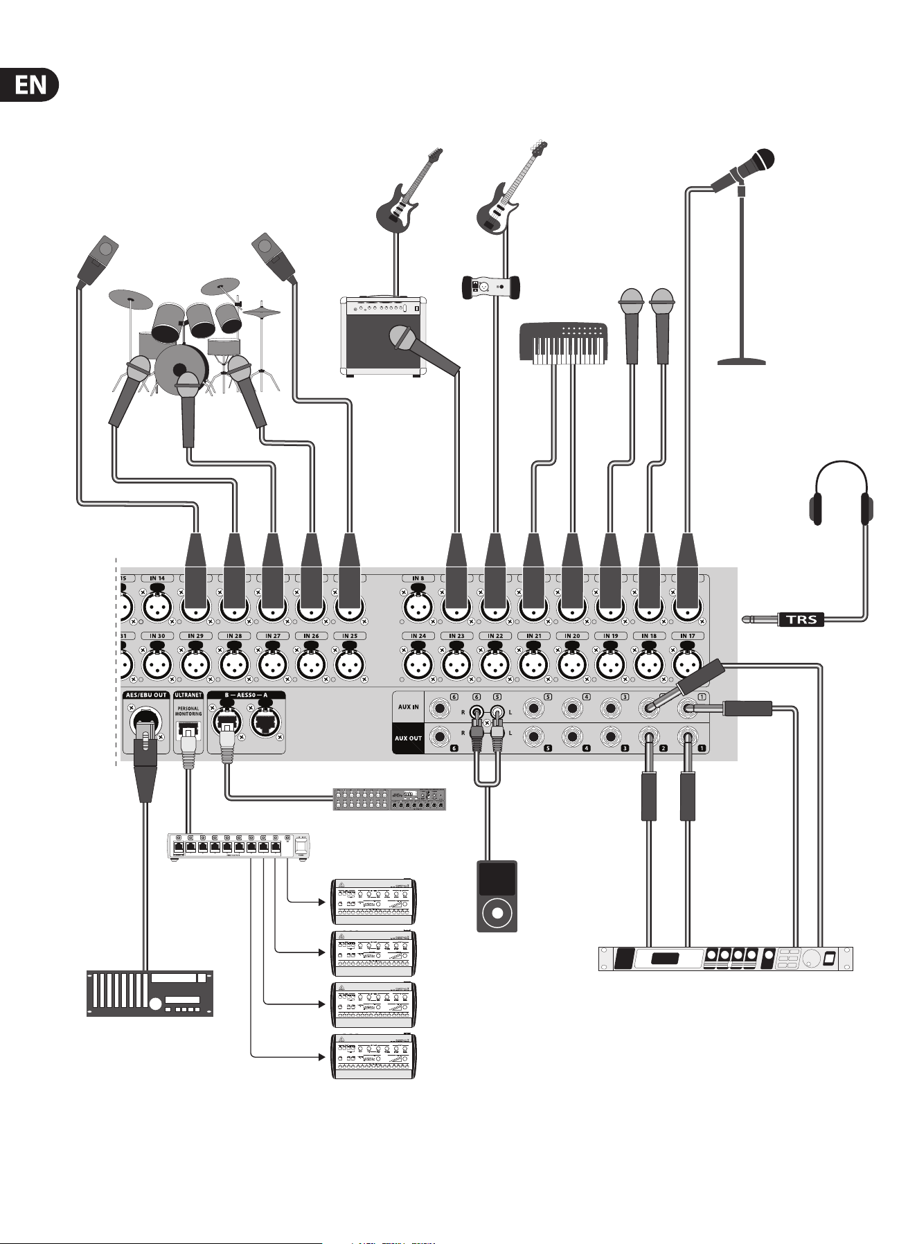
3. Hook-Up Diagrams
B1800D-PRO
B215D
F1320D
B3031A
Laptop
DI Box
GTX30
Keyboard
XM8500
2-TRACK HARD DISK RECORDER
FCB1010 MIDI Pedal
P-16 D
P-16 M
S16 Digital Snake
Shielded CAT-5e
iPod
FX2000
HPX6000
(Sidecap output)
20 X32 DIGITAL MIXER Preliminary User Manual
B1800D-PRO
B215D
F1320D
B3031A
Laptop
DI Box
GTX30
Keyboard
XM8500
2-TRACK HARD DISK RECORDER
FCB1010 MIDI Pedal
P-16 D
P-16 M
S16 Digital Snake
Shielded CAT-5e
iPod
FX2000
HPX6000
(Sidecap output)
Cabling for all AES50 connections between X32 and S16 stageboxes:
- Shielded CAT-5e, Ethercon terminated ends
- Maximum cable length 100 meters (330 feet)
21 X32 DIGITAL MIXER Preliminary User Manual
4. FX Descriptions
FX Descriptions
Here is a list and brief description of the eects available on the X32.
WhenStereoand Dual versions of an eect are oered, use the Stereo version
when the left and right signal are to be altered together (e.g. on linked stereo
channels or buses), or Dual when you want to dial dierent settings for the left
and right signal. See the Topic Guide for instructions on how to add eects to a
channel orbus.
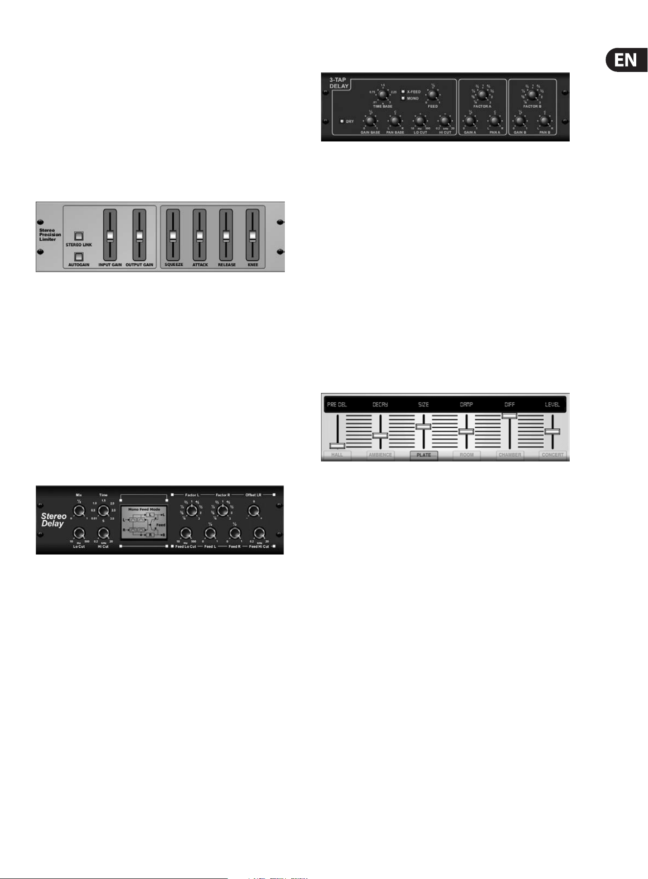
Stereo Precision Limiter
Stereo Precision Limiter allows you to set a precise volume limit,
ensuringdistortion-free, optimal signal integrity. Use X32’s Stereo Precision
Limiter to boost quiet signals or preventing clipping while preserving the level of
“hot”signals.
AUTOGAIN activates an additional long-term gain correction, allowing automatic
gain scaling of varying input level ranges. STEREO LINK applies limiting to both
channels equally when activated. INPUT GAIN provides up to 18 dB of gain to
the input signal prior to limiting. OUTPUT GAIN sets the nal gain level of the
processed signal. SQUEEZE adds compression to the signal to add punch and a
slight distortion depending on the amount you dial in. ATTACK sets the attack
time, ranging from 0.05 mS to 1 mS. RELEASE adjusts the release time from
0.05mS to 1.04 seconds. KNEE adjusts the soft limiting threshold point from hard
limiting (0 dB) to maximum soft limiting (10 dB).
Stereo Delay
Stereo Delay provides independent control of left and right delay (echo)
timesand features high and low pass lters for enhanced tone shaping of the
delayed signals. Use the Stereo Delay to give your mono signals a wide presence
in the stereo eld.
The MIX control lets you blend the source signal and the delayed signal.
TIMEadjusts the master delay time up to three seconds. LO CUT adjusts the low
frequency cut, allowing lower frequencies to remain unaected by the delay.
HI CUT adjusts the high frequency cut, allowing higher frequencies to remain
unaected by the delay. FACTOR L sets the delay on the left channel to rhythmic
fractions of the master delay time. FACTOR R sets the delay on the right channel
to rhythmic fractions of the master delay time. OFFSET LR adds a delay dierence
between the left and right delayed signals. The FEED LO CUT/HI CUT adjusts lters
in the feedback paths. FEED L and FEED R control the amount of feedback for
the left and right channels. MODE sets the feedback mode: Mode ST sets normal
feedback for both channels, X crosses feedbacks between left and right channels.
M creates a mono mix within the feedback chain.
Triple Delay
Sometimes called a 3-Tap Delay, the Triple Delay provides three delay stages with
independent frequency, gain, and pan controls. Create time-based echo eects
with the Triple Delay to increase the sense of stereo separation.
TIME BASE sets the master delay time, which is also the delay time for the rst
stage. GAIN BASE sets the gain level of the rst stage of the delay. PAN BASE sets
the position of the rst delay stage in the stereo eld. LO CUT sets the frequency
at which the source signal can begin passing through the delay. HI CUT sets the
frequency at which the source signal no longer passes through the delay. X-FEED
indicates that stereo cross-feedback of the delays is active. MONO activates
a mono mix of both channels for the delay input. FEED adjusts the amount of
feedback. FACTOR A controls the amount of delay time in the second stage of
the delay. GAIN A controls the gain level of the second delay stage. PAN A sets
the position of the second delay stage in the stereo eld. FACTOR B controls the
amount of delay time in the third stage of the delay. GAIN B controls the gain
level of the third delay stage. PAN B sets the position of the third gain stage in the
stereo eld.
Hall, Ambience, Rich Plate, Room, Chamber Reverb
These 5 reverb emulations are inspired by the Lexicon 480L. Hall simulates the
reverberation that occurs when sound is recorded in medium to large-sized
concert halls. Ambience creates a customizable virtual acoustic space to add
warmth and depth without coloring the direct sound.
The PRE DELAY slider controls the amount of time before the reverb is heard
following the source signal. DECAY controls the amount of time it takes for the
reverb to dissipate. SIZE controls the perceived size of the space being created by
the reverb. The DAMP slider adjusts the decay of the high frequencies within the
reverb tail. DIFF(usion) controls the initial reection density, and LEVEL controls
the eect output.
LO and HI CUT allow the frequencies aected by the reverb to be narrowed.
BASSMULT(iplier) controls the low frequency build-up. SPREAD emphasizes
the stereo eect of the reverb. SHAPE adjusts the contour of the reverberation
envelope. MOD SPEED controls the reverb tail modulation rate and TAIL GAIN
adjusts the volume of the reverb tail. The Rich Plate and Room reverbs allow the
stereo ECHO DELAY and the delay FEEDBACK to be adjusted independently for
each side. The Chamber reverb allows the stereo REFL(ection) DELAY and GAIN to
be adjusted independently.
22 X32 DIGITAL MIXER Preliminary User Manual
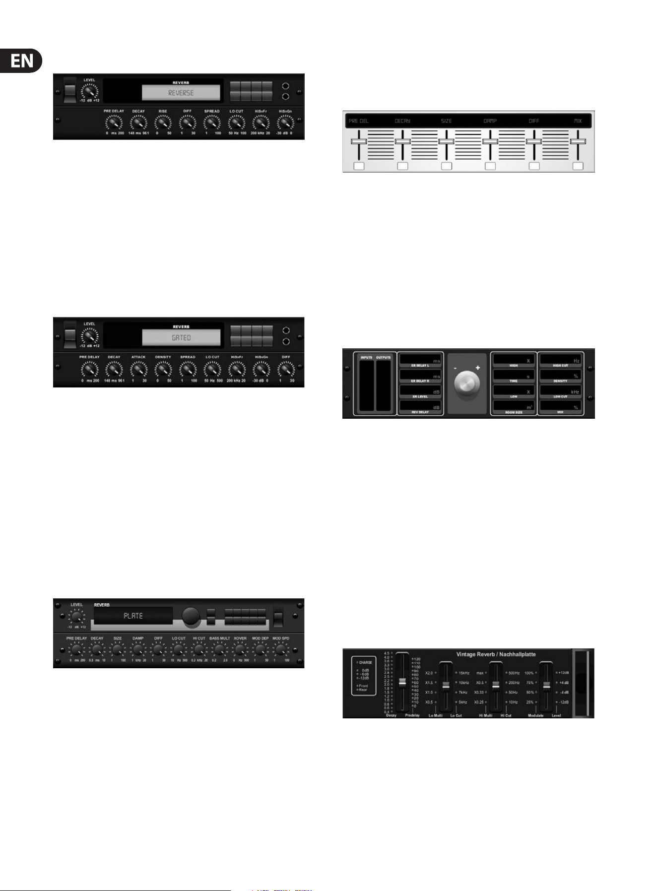
Reverse Reverb
Reverse Reverb takes the trail of a reverb, turns it around, and places it in front
of the sound source. Use the swelling crescendo of the Reverse Reverb to add an
ethereal quality to vocal and snare tracks. (Inspired by the Lexicon 300/480L)
Adjusting the PRE DELAY knob adds up to 200 milliseconds of time before the reverb
follows the source signal. The DECAY knob adjusts the time it takes for the reverb
to completely dissipate. RISE controls how quickly the eect builds up. DIFF(USION)
controls the initial reection density. SPREAD controls how the reection is
distributed through the envelope of the reverb. The LO CUT knob sets a low
frequency beneath which the source signal will not pass through the reverb. The
HiSvFr/HiSvGn knobs adjust a Hi-Shelving lter at the input of the reverb eect.
Gated Reverb
This eect was originally achieved by combining a reverb with a noise gate.
Ourgated reverb creates the same impression by a special shaping of the reverbtail.
Gated Reverb is especially eective for creating a 1980s-style snare sound or to
enlarge the presence of a kick drum. (Inspired by the Lexicon 300/480L)
PRE DELAY controls the amount of time before the reverberation is heard following
the source signal. DECAY controls the amount of time it takes for the reverb to
dissipate. ATTACK controls how fast the reection density builds up. DENSITY shapes
the reverb decay tail. The higher the density, the greater the number of sound
reections. SPREAD controls how the reection is distributed through the envelope
of the reverb. The LO CUT knob sets the frequency beneath which the source signal
will not pass through the reverb. The HiSvFr/ HiSvGn knobs adjust a Hi-Shelving lter
at the input of the reverb eect. DIFF(USION) controls the initial reection density.
Plate Reverb
A plate reverb was originally created by sending a signal through a transducer
to create vibrations on a plate of sheet metal which were then picked up as an
audio signal. Our algorithm simulates that sound with high initial diusion and a
bright colored sound. X32’s Plate Reverb will give your tracks the sound heard on
countless hit records since the late 1950s. (Inspired by the Lexicon PCM-70)
PRE DELAY controls the amount of time before the reverberation is heard
following the source signal. DECAY controls the amount of time it takes for the
reverb to dissipate. SIZE adjusts the size of the virtual room created by the reverb
eect. The DAMP knob adjusts the decay of high frequencies within the reverb
tail. DIFF(USION) controls the initial reection density. The LO CUT knob sets the
frequency beneath which the source signal will not pass through the reverb.
The HI CUT knob sets the frequency above which the source signal will not pass
through the reverb. The BASS MULT(IPLIER) knob adjusts the decay time of the
bass frequencies. XOVER controls the crossover point for bass. MOD DEPTH and
SPEED control the intensity and speed of the reverb tail modulation.
Hall Reverb
Classic Hall Reverb simulates the reverberation that occurs w hen sound is
recorded in medium to large-sized concert halls. Use the Hall Reverb to give your
mix a lush, three-dimensional quality that will make your performance sound
larger than life. (Inspired by the Lexicon Hall)
The PRE DELAY slider controls the amount of time before the reverberation is
heard following the source signal. DECAY controls the amount of time it takes for
the reverb to dissipate. SIZE controls the perceived size of the space being created
by the reverb eect. The DAMP slider adjusts the decay of high frequencies within
the reverb tail. DIFF(usion) controls the initial reection density. SHAPE adjusts
the contour of the reverberation envelope.
Vintage Room
Vintage Room simulates the reverberation that occurs when sound is recorded in
a small room. When you want to add a bit of warmth and just a touch of reverb,
X32’s Vintage Room breathes life into close-miced guitar and drum tracks.
(Inspired by the Quantec QRS)
The VU meter displays the input and output levels. Set the early reection times
for the left and right channel with ER DELAY L and ER DELAY R. ER LEVEL sets the
loudness of the early reection level. REV DELAY controls the amount of time before
the reverberation is heard following the source signal. HI/LOW MULTIPLY adjusts the
decay time of the high and bass frequencies. TIME shows the duration of the reverb
eect. ROOM SIZE adjusts the size of the room eect being created incrementally
from small to large. HIGH CUT sets the frequency above which the source signal
does not pass through the reverb. DENSITY manipulates the reection density in the
simulated room. (This slightly changes the reverb decay time). LOW CUT sets the
frequency below which the source signal does not pass through the reverb.
Vintage Reverb
Based on the legendary EMT250, X32’s Vintage Reverb delivers shimmering
bright reverb that won’t drown out or overpower your live or recorded tracks.
UseVintage Reverb to sweeten vocals and snare drums without sacricing clarity.
When layer 1 is selected, the rst slider on the left sets the reverb time from
4milliseconds to 4.5 seconds. Slider 2 controls the low frequency multiplier
decay time. Slider 3 controls the high frequency multiplier decay time. Slider 4
controls the amount of modulation in the reverb tail. When layer two is selected,
slider1adjusts the pre delay. Slider 2 selects the low cut frequency. Slider 3
selects the Hi Cut frequency. Slider 4 adjusts the output level of the reverb.
23 X32 DIGITAL MIXER Preliminary User Manual
When Layer 1 is selected, the far left encoder push button allows you to select
between virtual front and rear outputs. Rear is suitable for drums due to it being
less reective. Front is well-suited for vocals and other dynamic instruments.
TheVintage button enables the simulation of the input transformers.
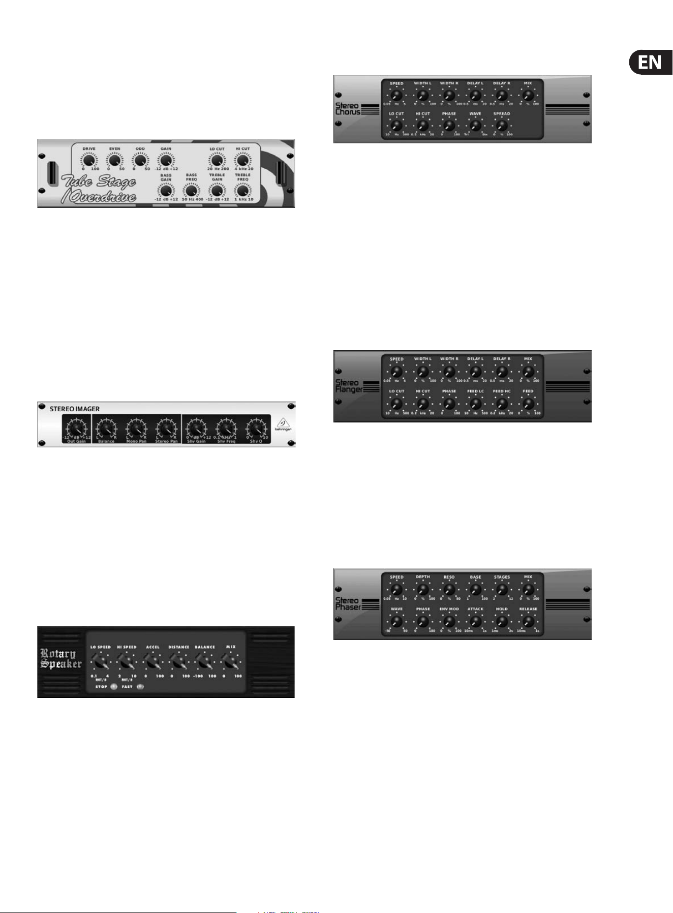
Stereo/Dual Tube Stage/Overdrive
Tube Stage/Overdrive is a versatile eect capable of emulating a variety of
modern and classic tube preamps. Available in stereo and dual-mono versions,
use Tube Stage/Overdrive to dial in warm and fuzzy sounds from subtle to
fullysaturated.
DRIVE adjusts the amount of harmonics being driven by the eect. EVEN and ODD
adjust the amount of even and odd harmonics. GAIN adjusts the output gain of
the eect. LO CUT sets the input frequency below which the source signal will not
pass through the eect. HI CUT sets the input frequency above which the input
signal will not pass through the eect. BASS GAIN/FREQ adjust a low shelving
lter at the output of the eect. TREBLE GAIN/FREQ adjust a high shelving lter at
the output of the eect.
Stereo Imager
A Stereo Imager is typically used to control the placement of a signal within the
stereo eld during mixdown or mastering. Modeled after the BEHRINGER Edison
rack unit, X32’s Stereo Imager will lend a professional quality to your live and
recording performances.
The BALANCE knob allows you to emphasize the mono or stereo components
of the input signal. The mono and stereo signals can be panned independently
with the MONO PAN and STEREO PAN knobs. OUT GAIN is used to compensate for
level changes resulting from the eect. The phase can also be shifted using the
shelving knobs. Select the frequency and bandwidth (Q) using the corresponding
knobs, then adjust the gain with the SHV GAIN knob.
Rotary Speaker
Rotary Speaker emulates the sound of a Leslie rotating speaker. X32’s Rotary
Speaker provides more exibility than its electro-mechanical counterpart,
andcan be used with a variety of instruments, and even vocals, to create a
whirling, psychedelic eect.
The LO SPEED and HI SPEED knobs adjust the rotational speed of the
SLOWandFAST Speed selection, and can be toggled with the FAST button.
TheACCEL(eration) knob adjusts how quickly the speed increases and decreases
from the Slow mode to the Fast mode. The rotation eect can also be disengaged
with the STOP button, which will stop the movement of the speakers.
DISTANCE adjusts the distance between the Rotary speakers and the
virtualmicrophone.
Chorus / Stereo Chorus
Chorus samples the input, slightly detunes it and mixes it with the original
signal to produce a somewhat thicker, shimmering sound. Use it to thicken up
background vocals, or to double the sound of brass and woodwind instruments.
Where as DELAY L/R set the total amount of delay for the left and right channel,
WIDTH determines the amount of modulated delay. SPEED sets the modulation
speed. MIX adjusts the balance of the dry and wet signals. You can further sculpt
the sound by trimming some of the low and high end from the eected signal
with the LO and HI CUT knobs. Additionally, the PHASE knob can tweak the
phase oset of the LFO between left and right channel and the SPREAD knob
adjusts how much of the left channel is mixed into the right and vice versa.
Finally,theWAVE knob blends between the “Danish-style” digital triangular
chorus sound and the classic analog sine wave.
Flanger / Stereo Flanger
The Flanger emulates the phase-shifting sound (comb-ltering)
originallycreated by applying pressure against the ange of the reel on a tape
recorder. This eect creates a unique “wobbly” sound that is quite dramatic when
used on vocals and instruments.
The controls of this eect are nearly identical to the Chorus eect block.
Additionally, the FEEDBACK can be adjusted with positive and negative amounts
and also band-limited with the FEED HC (high-cut) and FEED LC (low-cut) knobs.
Stereo Phaser
A Stereo Phaser, or phase shifter, applies multiple STAGES of modulated lters to
the input signal to create a “notch” in the frequency response, and then applies
a MIX with the original for a “swirling” eect. Use X32’s Stereo Phaser to add a
“spaced-out” sound to vocal or instrument tracks.
SPEED adjusts the LFO rate and DEPTH sets the LFO modulation depth.
The BASE knob adjusts the frequency range of the modulated lters.
Theresonance is adjusted with the RESO knob. The WAVE knob shapes the
symmetry of the LFO waveform and PHASE dials in an LFO phase dierence
between the left and right channel. The modulation source can also be the signal
envelope, which produces vowel-like opening and closing tones. The ENV MOD
knob adjusts how much this eect takes place (positive and negative modulation
is possible), and the ATTACK, HOLD and RELEASE knobs all tailor the response of
this feature.
24 X32 DIGITAL MIXER Preliminary User Manual
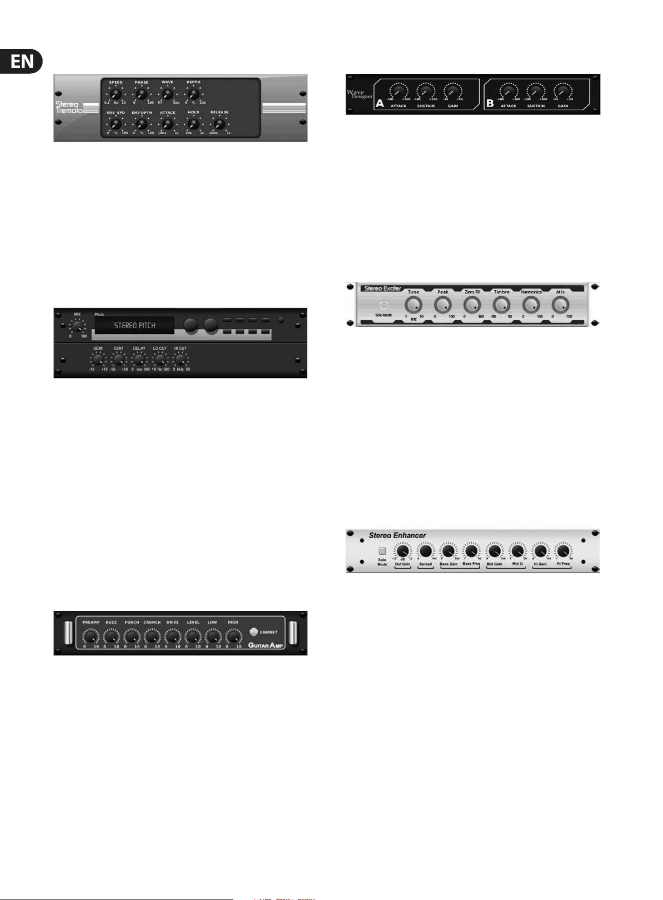
Tremolo / Panner
Stereo Tremolo creates an up and down volume change at a constant and even
tempo just like the guitar amps of yesteryear. Use X32’s Stereo Tremolo to add a
unique “surf-music” texture to a vocal or instrument track.
SPEED adjusts the LFO rate and DEPTH sets the amount of modulation.
PHASEcanbe used to set an LFO phase dierence between the left and right
channel, which can be used for panning eects. The WAVE knob blends the LFO
waveform between triangular and square shape. The signal envelope, shaped by
ATTACK, HOLD and RELEASE, can be used to modulate the LFO speed (ENV SPEED)
and the LFO modulation depth (ENV DEPTH).
Stereo / Dual Pitch
Pitch shifting is often used in two dierent ways. One is to set the Mix knob lower
and only use the Cent knob to make a small oset in pitch between the wet and
dry tones. This results in a “voice doubling” eect that thickens the overall sound
in a more subtle way. The extreme use of the eect is to turn the Mix knob fully-
clockwise so the entire signal is eected. This way, the signal can be shifted into
other keys up to an octave above or below the original. When used on a voice,
this results in a “chipmunk” sound or a low Darth Vader eect.
When the SEMI and CENT knobs are set at 12:00, the pitch is not altered.
Makingadjustments by semitone will have a very pronounced eect,
whereaschanges to the CENT knob will be very minor. The DELAY knob creates a
time dierence between the wet and dry sound. The LO and HI CUT knobs allow
the eected signal to be band-limited. The Dual Pitch eect allows the left and
right channels to be adjusted independently, and allows GAIN compensation and
panning of the two channels.
Stereo / Dual Guitar Amp
Modeled after the Tech 21 SansAmp, the Stereo / Dual Guitar Amp simulates the
sound of plugging into a real guitar amp. From shimmering cleans to saturated
crunch, X32’s Stereo / Dual Guitar Amp allows an electric guitar player to sound
great without using an amp on stage.
The PREAMP knob adjusts the amount of input gain prior to the band-specic
distortion adjustment. BUZZ adjusts the low-end breakup, PUNCH adjusts
the midrange distortion, and CRUNCH tailors the high-frequency content and
distortion for smooth or cutting notes. The DRIVE knob simulates the amount
of power amp distortion from a tube amp. The LOW and HIGH knobs allow
EQ adjustment independent of distortion content, and the overall output is
controlled by the LEVEL knob. The CABINET simulation can be bypassed if the
guitarist is already using a real cab, which allows the eect to function like a
boost or distortion pedal. The Dual Guitar Amp allows the left and right channels
to be adjusted independently.
Wave Designer
Wave Designer is a powerful tool for adjusting signal transients and dynamics,
such as attack and sustain. Use it to make a snare drum really “crack” in the
mix or level out volume inconsistencies of slap bass tracks. (Inspired by the SPL
Transient Designer)
Adjusting the ATTACK knob can add punch or tame overly dynamic signals.
Increasing the SUSTAIN knob acts in a similar way as a compressor, allowing the
peaks to carry longer before decay. The eect can also be used to reduce the
sustain for a more staccato sound. The GAIN knob compensates for level changes
caused by the eect.
Stereo Exciter / Dual Exciter
Exciters increase presence and intelligibility in live sound applications, and are
indispensable for adding clarity, air and harmonic overtones in the recording
studio. This eect is particularly useful for lling out the sound in dicult rooms
and for producing a more natural live/recorded sound. (Inspired by the famous
Aphex Aural Exciter)
Set the frequency of the side-chain lter with the TUNE knob, and further shape
the lter slope with the PEAK and ZERO FILL knobs. Turning the TIMBRE knob
left of center adds more odd harmonics, while turning it right of center adds
more even harmonics. Adjust the harmonic content added to the signal with
the HARMONICS knob, and blend in the eected signal with the MIX knob.
Engagethe SOLO MODE to isolate only the audio resulting from the eect so you
can hear exactly what you’re adding to the mix.
Stereo Enhancer / Dual Enhancer
X32’s Enhancers are so called “Psycho EQs”. They can enhance the signal
spectrum in bass, midrange and high frequencies but they dier from traditional
equalizers. When you need to generate maximum punch, clarity and detail,
without turning up the overall volume, our enhancers are the solution.
(Inspiredby the SPL Vitalizer)
Adjust the BASS, MID and HI GAIN knobs to add or reduce content in those
spectrums. The BASS and HI FREQuencies can be specically selected, while the
MID Q (bandwidth) can be adjusted instead. The OUT GAIN knob compensates for
changes in level resulting from the eect, and the SPREAD knob (Stereo version
only) emphasizes the stereo content for a wider mix. Engage the SOLO MODE
to isolate only the audio resulting from the eect so you can hear exactly what
you’re adding to the mix.
25 X32 DIGITAL MIXER Preliminary User Manual
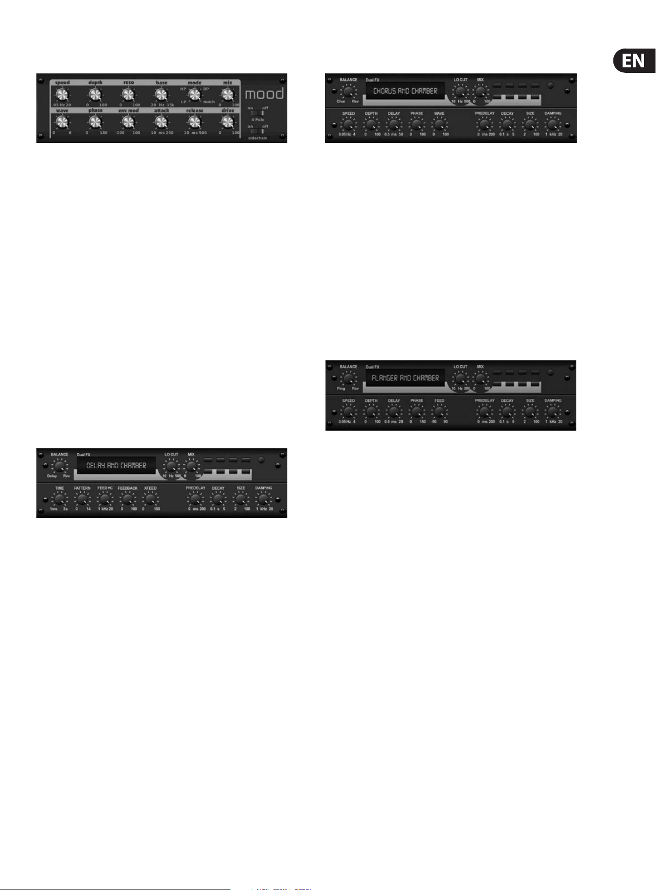
Mood Filter
The Mood Filter uses an LFO generator and an auto-envelope generator to control
a VCF (voltage-controlled lter), as well as a side chain function where the
channel B signal controls the envelope of channel A. When applied to electronic
instruments, the Mood Filter can be used to emulate the natural sound of
acoustic instruments. (Inspired by the MiniMoog)
This lter can be modulated with the signal’s envelope using the ENV MOD
(withpositive and negative amounts), ATTACK and RELEASE knobs, or the LFO
can modulate the lter. The WAVE knob selects between 7 dierent wave forms
– triangular, sine, saw plus, saw minus, ramp, square, and random. The PHASE
can be oset by up to 180 degrees. The SPEED knob adjusts the rate of the LFO
and the DEPTH adjusts the amount of LFO modulation. Adjust the resonance of
the lter until self-oscillation with the RESO(nance) knob. BASE adjusts the range
of the lter from 20 Hz to 15 kHz. The MODE switch selects between low pass
(LP), high-pass (HP), band-pass (BP) and Notch. Use the MIX knob to blend the
eected signal with the dry sound. With the 4 POLE switch engaged, therewill
be a steeper slope than the OFF (2 pole) setting. The DRIVE knob adjusts the
level and can also introduce an overdrive eect (as with real analogue lters)
ifpushed hard. In Sidechain mode, only the left input signal is processed and
fed to both outputs. The envelope of the right input signal can be used as a
modulationsource.
Delay + Chamber
Here we have combined Delay and Chamber reverb, so a single device can provide
a variety of delay settings, plus add just the right type and amount of reverb to
the selected signal. This device only uses one FX slot. (The Reverb is Inspired by
the Lexicon PCM 70)
Use the BALANCE knob to adjust the ratio between delay and reverb.
Lowfrequencies can be excluded with the LO CUT knob, and the MIX adjusts
how much of the eect is added to the signal. The TIME knob adjusts the delay
time for the left channel delay, and the PATTERN sets the delay ratio for the
right channel delay. Adjust the FEEDBACK and trim some high frequencies with
the FEED HC (high-cut) knob. The XFEED knob allows you to send the delay
sound to the reverb eect, so instead of running completely parallel, the reverb
eects the echos to a selected degree. The PREDELAY knob determines the
hesitation before the reverb aects the signal. The DECAY knob adjusts how
quickly the reverb fades. The SIZE controls how large or small the simulated
space is (room,cathedral, etc.). The DAMPING knob determines the decay of high
frequencies within the reverb tail.
Chorus + Chamber
Taking up only one FX slot, the Chorus + Chamber eect combines the shimmer
and doubling characteristics of a studio-grade Chorus with the sweet sound of a
traditional Chamber reverb. (Reverb is Inspired by the Lexicon PCM 70)
The BALANCE knob adjusts the balance between chorus and reverb. Low
frequencies can be excluded with the LO CUT knob, and the MIX knob adjusts
how much of the eect is added to the signal. SPEED, DELAY and DEPTH adjust
the rate, delay, and modulation depth of the chorus. The LFO PHASE between left
and right channel can be oset by up to 180 degrees, and WAVE adjusts the LFO
waveform from a sine wave to triangular wave. The PREDELAY knob determines
the hesitation before the reverb aects the signal. The DECAY knob adjusts how
quickly the reverb fades. The SIZE controls how large or small the simulated
space is (room, cathedral, etc.). The DAMPING knob determines the decay of high
frequencies within the reverb tail.
Flanger + Chamber
Add the mind-bending, lter-sweeping eect of a state-of-the-art Flanger to
the elegant sweetening of a traditional Chamber reverb—all in one FX slot.
(Reverbis Inspired by the Lexicon PCM 70)
The BALANCE knob adjusts the ratio between anger and reverb. Low frequencies
can be excluded with the LO CUT knob, and the MIX knob adjusts how much of
the eect is added to the signal. SPEED, DELAY and DEPTH adjust the rate, delay,
and modulation depth of the anger. FEEDback can be adjusted with positive and
negative amounts. The PHASE can be oset by up to 180 degrees. The PREDELAY
knob determines the hesitation before the reverb aects the signal. The DECAY
knob adjusts how quickly the reverb fades. The SIZE controls how large or small
the simulated space is (room, cathedral, etc.). The DAMPING knob determines the
decay of high frequencies within the reverb tail.
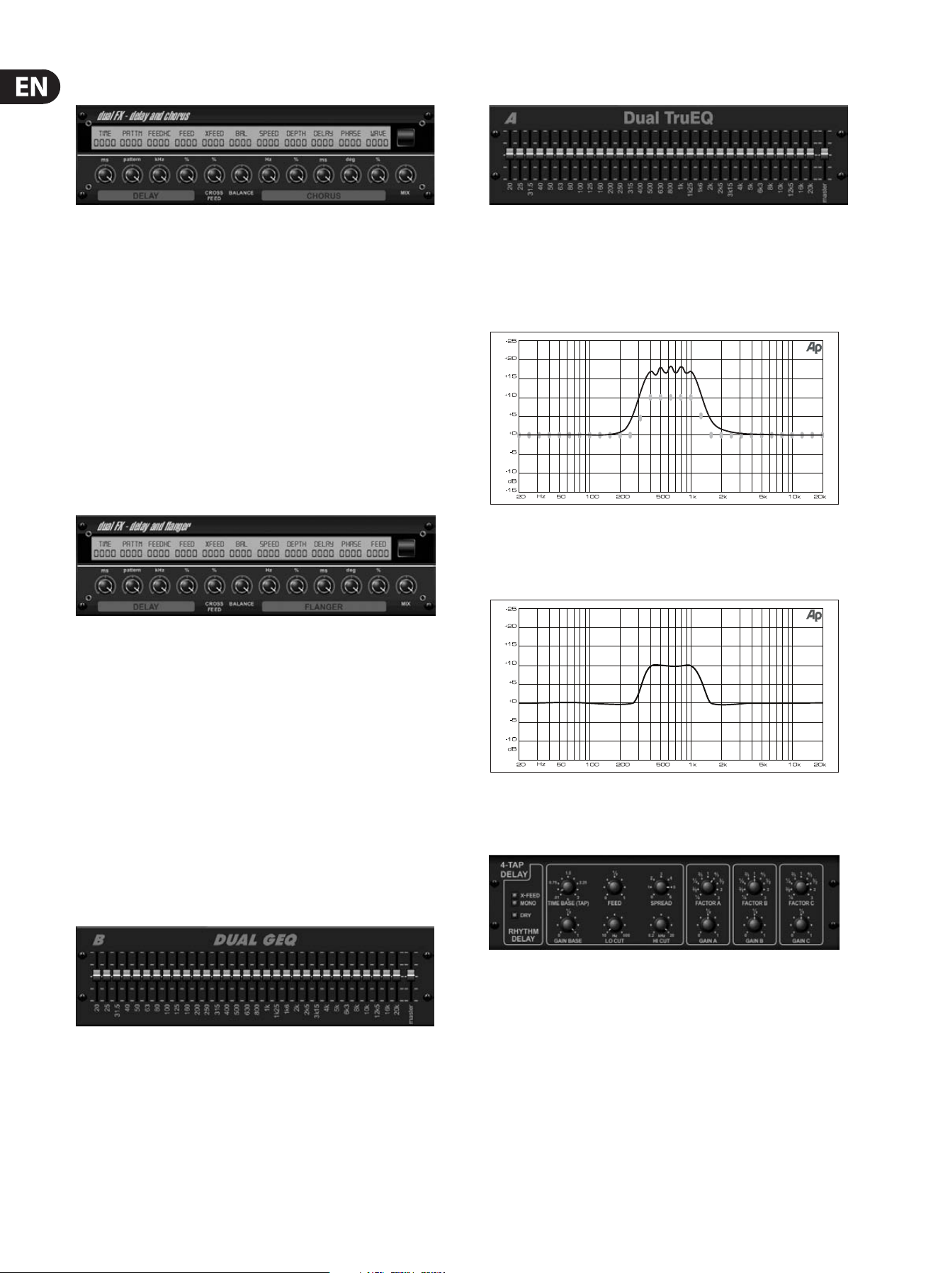
26 X32 DIGITAL MIXER Preliminary User Manual
Delay + Chorus
This combination eect merges a user-denable Delay (echo) with a studio-
quality Chorus sure to fatten up even the “skinniest” track. Uses only one FX slot.
(Inspired by the TC Electronic D-Two)
The TIME knob adjusts the delay time, and the PATTERN knob sets the delay ratio
for the right channel and negative values activate a cross feedback between
the two channels. The FEEDHC knob adjusts the delay high-cut frequency,
whilethe FEEDBACK knob adjusts the number of repeats. The X-FEED knob allows
you to send the delay sound to the chorus eect. The BALANCE knob adjusts
the ratio between delay and chorus. SPEED, DELAY and DEPTH adjust the rate,
delay,andmodulation depth of the chorus. The right channel LFO PHASE can be
oset by up to 180 degrees, and WAVE adjusts the chorus character by shaping
the LFO waveform from sine wave to triangular wave. Use the MIX knob to blend
the eected signal with the “dry” sound.
Delay + Flanger
This handy dynamic duo blends the “woosh” of soaring jet planes with classic
Delay, and can be adjusted from mild to wild. This combination eect only takes
up one FX slot. (Inspired by the TC Electronic D-Two)
The TIME knob adjusts the delay time, and the PATTERN knob sets the delay ratio
for the right channel and negative values activate a cross feedback between
the two channels. The FEEDHC knob adjusts the delay high-cut frequency,
whilethe FEEDBACK knob adjusts the number of repeats. The X-FEED knob
allows you to send the delay sound to the anger eect. The BALANCE knob
adjusts the ratio between delay and anger. SPEED, DELAY and DEPTH adjust the
rate, delay, andmodulation depth of the anger. The right channel LFO PHASE
can be oset by up to 180 degrees, and FEED (positive and negative amounts)
adjuststhe feedback eect. Use the MIX knob to blend the eected signal with
the “dry”sound.
Dual / Stereo GEQ
These are standard graphic equalizers that provide 31 bands of adjustment
between 20 Hz and 20 kHz. A master volume slider compensates for changes in
volume caused by the equalization. A maximum boost or cut of 15 dB is available
for each band.
Dual / Stereo TruEQ
The TruEQ incorporates a special algorithm that compensates for the gain
adjustment overlapping eect that adjacent frequency bands have on one
another. On a standard EQ, when neighboring bands are boosted together,
theresulting eect is magnied beyond what is visible from the positioning of
thesliders.
Graphic equalizer without frequency response correction.
This compensated EQ will produce an adjustment that is identical to the actual
positioning of the sliders.
Graphic equalizer with frequency response correction.
Rhythm Delay
The Rhythm Delay provides 4 stages of delay with independently adjustable gain
and rate, allowing unique syncopation to be created in the layered repeats.
TIME BASE sets the master delay time, which is also the delay time for the rst
stage. GAIN BASE sets the gain for the rst stage. SPREAD positions the rst delay
stage in the stereo eld. A global FEEDBACK, LO and HI CUT adjustment are also
available. FACTOR A, B and C adjust the delay rate relative to the global TIME BASE
setting for the 2nd, 3rd and 4th stages respectively. Each stage also has its own
GAIN adjustment. MONO activates a mono mix of both channels for the delay
input. X-FEED indicates that stereo cross-feedback of the delays is active.
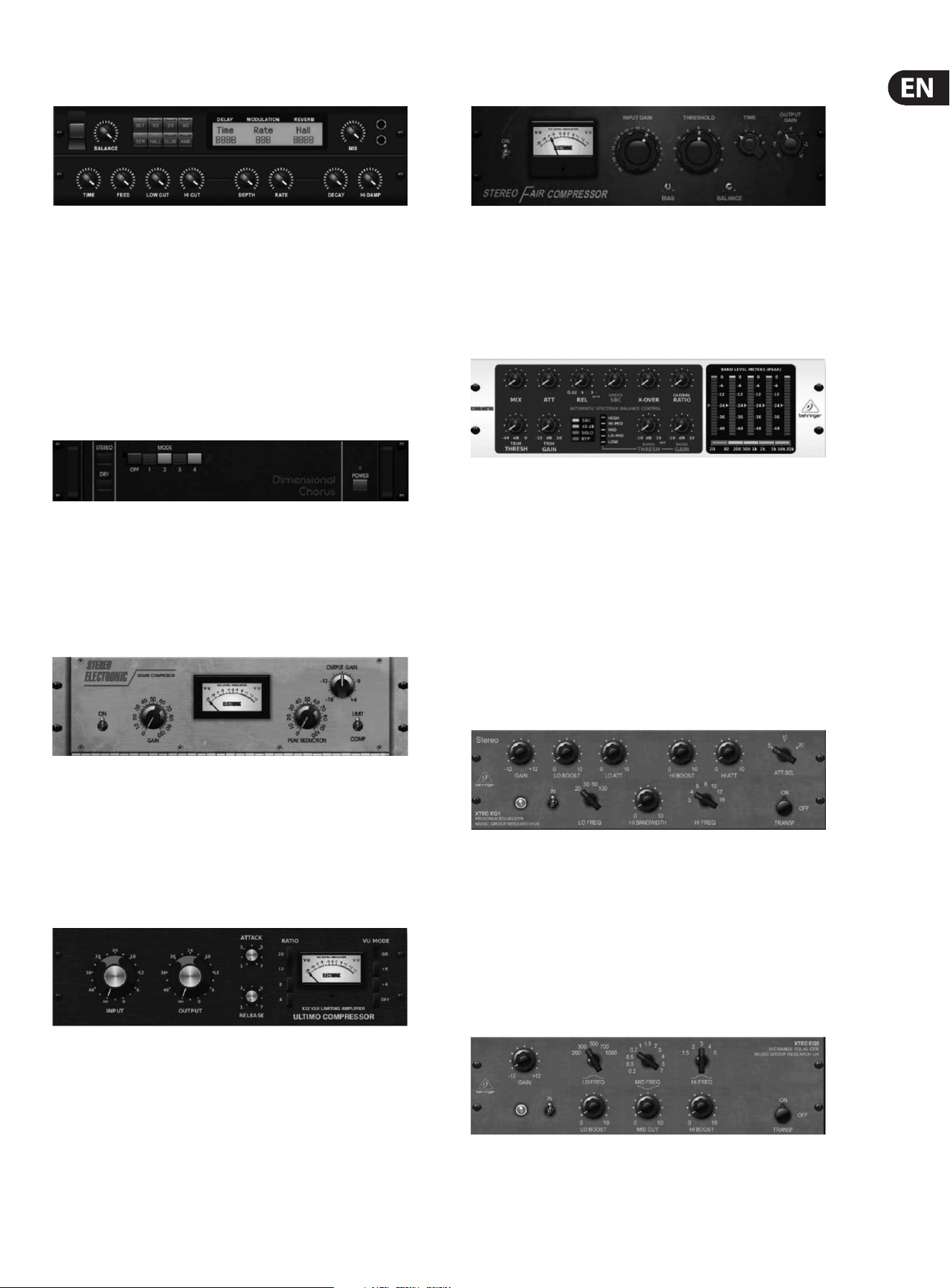
27 X32 DIGITAL MIXER Preliminary User Manual
Modulation Delay
Modulation Delay combines three of the most used time modulation eects
into one easy-to-operate unit, featuring true-stereo delay with a lush chorus,
topped o with three reverb models to choose from.
The BALANCE knob adjusts ratio of delay to reverb. The processor chain can
operate as serial where one eect ows into the next, or parallel where
each eect is applied to the source signal independently. TIME, FEED (back),
LOW and HI CUT all aect the delay. Modulation DEPTH and RATE are adjustable.
Three types of reverb are available – ambience, club and hall – with adjustable
DECAY and HI DAMP.
Dimensional Chorus
The Dimensional Chorus oers the most user-friendly and classic sounds,
best described as “space” and “dimensional”. The 4 MODE buttons can
be engaged individually or simultaneously for light chorus or very thick,
exaggerated modulation. Adjust the 1st encoder to select mono or stereo
operation, and press the encoder to engage or bypass the eect.
Leisure Compressor
This model of a popular tube-based optical compressor provides natural and
eortlessly musical compression, inspired by the Teletronix LA-2A. Simply adjust
the input GAIN and PEAK REDUCTION knob to dial in the amount of desired
compression, then adjust the OUTPUT GAIN knob for the desired output level.
The COMP setting will give a gentle compression ratio, whereas the LIMIT setting
results in a higher ratio.
Ultimo Compressor
The Ultimo Compressor is based on the Urei 1176LN Limiting Amplier and
authentically captures the smooth character of the original class-A output stage
in its FET's legendary fast attack.
Start with the INPUT and OUTPUT knobs at the -24 position for unity gain and set
the ATTACK and RELEASE knobs fully counterclockwise. Select the compression
ratio, then raise the ATTACK knob to lightly compress the signal. Increase the ratio
for heavier compression and experiment with ATTACK, RELEASE and INPUT levels
to achieve your desired result. Compensate for overall level reduction with the
OUTPUT knob.
Fair Compressor
This model of a Fairchild 670 delivers some of the nest colorations in compressor
history. Two small trim VRs, BIAS and BALANCE, preset the control side chain
action, a 6-step knob determines the timing, and the 2 large INPUT GAIN
and THRESHOLD knobs adjust the levels. There are models available for dual,
stereo-linked, or mid/side operation.
Combinator
The Combinator emulates famous broadcasting and mastering compressors,
utilizing automatic parameter control that produces very eective yet
“inaudible” results.
The MIX knob allows some of the source signal to pass through unaected.
ATTACK and RELEASE have dedicated controls, and an Auto Release function can
be engaged. Global X-OVER, RATIO, THRESH(old) and GAIN controls are available.
Engage the Spectral Balance Control (SBC) to allow automatic gain balancing
between the audio bands and its SPEED control to determine how aggressively
the eect works. The meters can also display band reduction or the SBC gain
balance, and can display peak outputs. The THRESH(old) and GAIN can be
adjusted for each band independently.
XTEC EQ1
Inspired by the Pultec EQP-1a, this passive equalizer is a very powerful tool for
sound enhancement.
GAIN allows compensation for level changes resulting from frequency
adjustments. Press the 1st encoder to engage or disengage the eect. Select the
low frequency with the LO FREQ knob, adjust the amount of enhancement with
the LO BOOST, then adjust the attack with the LO ATT. The same adjustments are
available for the high frequencies.
XTEC EQ5
This Pultec emulation is a classic analog passive equalizer that offers very warm and musical
frequency sculpting. Simply select the center frequency for the 3 bands, then adjust how much low
and high you want to boost and how much midrange you want to cut.
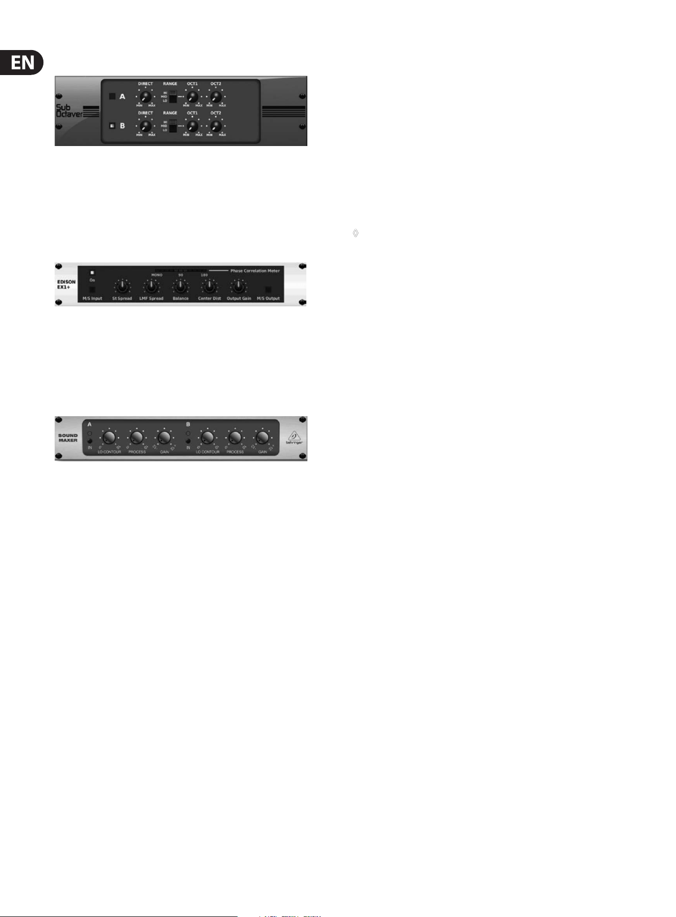
28 X32 DIGITAL MIXER Preliminary User Manual
Sub Octaver
The Sub Octaver provides two channels of sub harmonics generation, one or even two octaves below
the input signal.
Adjust the DIRECT knob to blend the “dry” signal with the lower octaves. Use the RANGE switch
to optimize the tracking by selecting the frequency range of the input signal. The OCT1 and OCT2
knobs adjust how much 1 octave down and 2 octaves down content is included.
Edison EX1
The EDISON EX1+ is a remarkably effective tool that allows manipulation of the stereo
field. The effect offers stereo and mid/side input and output and a phase correlation meter.
Exaggerate the stereo field with the ST SPREAD knob and adjust the ratio of mono to stereo
content with the BALANCE knob. The CENTER DIST knob allows the mono content to be panned.
Compensate for level changes with the OUTPUT GAIN knob.
Sound Maximizer
Inspired by the Sonic Maximizer 482i, this effect restores natural brilliance and clarity to any audio
signal by adjusting the phase and amplitude integrity to reveal more of the natural texture of the
sound. LO CONTOUR adjusts the level of phase-corrected low frequencies and PROCESS adjusts the
level of phase-corrected high frequencies. GAIN compensates for level changes caused by the effect.
5. Topic Guide
5.1 Starting up, shutting down,
and rmware updates
We recommend switching the X32 on before any active sound reinforcement
system is connected. The function called “Safe Main Levels”, located in the
Setup/General Preferences screen, automatically turns down the main LRC bus
levels when booting the console, and also prevents any scene loading actions
from aecting (specically turning up) the main levels.
Synchronization and Sample Rate settings can also be adjusted on the
Setup/Cong page, but please note that changing the sample rate will require a
console reboot.
◊ Please Note: Settings under ‘Link Preferences’, ‘Panning Mode’,
and ‘DCA groups’ are stored with the Scene data while all other settings
made on the Setup/Config page are not stored in any preset and will
not be initialized either. Please verify before using the X32 that the
sample rate is set correctly and if the synchronization source is selected
appropriately. If set to external synchronization via one of the two
AES50 ports, while no clock source is actually connected or switched on,
then the corresponding small square icon in the main display’s top row
would be red rather than green. In normal state you should only see
1-4 green squares in the top section depending on the units connected.
Note that if the X32 console has previously been in use by somebody else, and you
feel unsure about its actual status, you can reset it to default settings in either of
two convenient ways:
1. While the console is booting up and the “X32” logo appears on the screen,
press and hold the “Scenes / UNDO” button, keeping it depressed until the
console is fully operational and the Home screen is displayed. The console
will now be in the exact same state as it was when rst shipped from the
factory. However, you can immediately revert back to the status the console
was in before being switched o by pressing the Scenes/UNDO button.
2. You can also reset the console any time after booting by pressing
“Setup/Cong” -> “Initialize”.
The X32 regularly stores the console’s status to its onboard ash memory,
sothere is usually nothing wrong with switching it o, and you do not have to
explicitly save the current status. However, when a large number of parameters
have been recently changed, storing all of them to ash can take up to 1 minute,
in a “worst-case” scenario. In order to prevent any errors by losing power during
this type of storage operation, we recommend using the “Safe Shutdown”
function from the Setup/Global page, an operation similar to un-mounting a
USBthumb-drive from your PC.
Console Lock
To lock the console and prevent tampering with the panel controls, simply hold
the HOME button depressed for 3 seconds. To unlock, hold the HOME button
again for 3 seconds. This can also be used as a safe shutdown by locking the
console before switching the power o.

29 X32 DIGITAL MIXER Preliminary User Manual
Updates:
The X32 rmware can easily be updated by performing the following steps:
• Download the new console rmware from the X32 product page onto the
root level of a USB thumb drive
• Plug the USB thumb drive into the front panel USB connector while the
console is turned o
• Hold the USB View button depressed while switching the console on.
While booting, the X32 will run a fully automatic rmware update,
which will take 2-3 minutes longer than the regular boot sequence
When no update le is available on the USB drive, or when it is corrupted, the
update mode will remain active, preventing the X32 from booting regularly.
Switch the console o and back on without holding the USB View button to boot
the console with the existing rmware.
The USB socket is not suitable for other non-memory USB devices like keyboards,
mice, lamps, etc.
5.2 Default setup for connecting to monitoring
and P.A. systems
The X32 comes pre-congured with the local XLR inputs connected to input
channels 1-32, and XLR outputs 1-14 connected to the mix bus masters 1-14.
Busmasters 13-16 are connected to the eects inputs FX1-4. The Main LR (stereo)
signal is normally put out on XLR outputs 15/16.
The Monitoring outputs on ¼" and XLR connectors, and the two Phones outputs
(in the side-cap handles) always carry either the Monitor Source signal or any solo
signal, whenever a solo button is active. Press the View button in the Monitor
section to check or change the solo and monitoring preferences.
1. Power up the X32 console rst, before any connected power amps or
speakers are switched on.
2. Connect cables to XLR outputs 15 and 16 on the rear panel, connecting the
other ends of the cables to the inputs of your P.A. system. These normally
carry the main stereo bus left and right.
3. All buses or input channels that are to be put out on the main PA system
must have their Stereo Bus switches on. Use the selected channel’s pan
control to place the signal within the main stereo eld, and the channel’s
fader to set the volume.
4. Use the rear panel Monitoring outputs to connect monitor speakers or, ifyou
prefer, use the ¼" outputs in the sidecaps to connect your head phones.
Youwill either hear the monitor source signal, which is Main Stereo by
default, or any channel with its solo button being active.
5.3 How do I connect a microphone, process its
signal and send it out to the P.A. system?
1. Press the Select button of a desired input channel (for example, channel 1 on
the “Channels 1-16” input layer) and make sure the channel fader is down.
2. In the channel processing section in the upper left hand corner, make sure
the phantom power is switched o.
3. Connect a microphone to XLR input 1 on the X32’s rear panel.
4. Press the 48V button to switch phantom power on for channel 1
(if the microphone requires it, such as a condenser microphone).
Note - It is best practice to mute the respective channels prior to switching
their phantom power supply on or o. Otherwise, the change of charge
may cause an audible popping noise. Gain adjustments might also produce
audible click noise when adjust shortly after having switched phantom
power on or o.
5. Use the Gain control to adjust the gain level as necessary, using the input
meter as a guide.
6. Switch on and adjust the Low Cut lter as needed to remove rumble or
windnoise.
7. Adjust the channel equalizer controls to sculpt the sound quality of the
microphone signal.
8. Adjust the channel Gate and Compressor controls as desired. Note that by
pressing the “view” button in the compressor or gate section, the main
screen will switch to the compressor or gate display for the selected channel,
oering additional compressor or gate controls beyond the dedicated
top-panel controls.
9. Turn on the “Stereo Bus” switch in order to route the selected signal to
the main LR, then adjust the Pan control to place the signal within the
stereoeld.
10. Adjust the Channel 1 fader to the 0 dB region, then slowly turn up the main
LR fader until you hear the mic signal amplied through your P.A. system.w

30 X32 DIGITAL MIXER Preliminary User Manual
5.4 How do I add one of the 8 internal eects
to the sound?
There are two types of eects that are commonly used:
• “Eects Loop” (side chain) style eects, where multiple channels all send
varying amounts of their signal to a common eect, such as a reverb,
delay,or chorus.
• “Insert” style eects that are inserted in to the signal path of a single
channel of audio. Examples would be a graphic EQ, lter, exciter,
ortubeemulator.
To apply an “Eects Loop” style eect:
• Press the “FX” menu button. The main screen will show the FX home screen
where dierent eects processors are assigned to the 8 processing slots.
• Adjust rotary encoder #6 to highlight the rst eects processor; it will be
surrounded by an orange outline.
• Adjust rotary encoder #1 and rotary encoder #2, selecting your desired bus
as the source for both the left and right inputs of the rst eect processor.
Bydefault, FX 1 is sourced from Bus 13.
• Adjust rotary encoder #5 to select a specic eect processor,
suchas “Ambience”.
• Select the fader bank button labeled “RTN” on the left side of the console.
Bring the faders labeled FX1L and FX1R up to 0 dB in case they are not set to
this value by default. In the initial setup, these returns are stereo linked and
automatically send to the main LR bus, but it is also possible to send them to
the other buses as well. For this, press the HOME button next to the screen
while the return is selected, then go to the SENDS tab with the PAGE SELECT
right button and adjust the send levels for the return to the other buses,
oruse the dedicated BUS SENDS controls.
• Back on the EFFECTS page, press the PAGE SELECT right button to switch the
screen to the editor for the Ambience processor. The screen will switch to an
editor page for the rst processor. Adjust the rotary encoders to tailor the
eect to your liking.
• To apply the eect to assorted input channels, select an input channel,
thenadjust its “Bus Send 13” knob to taste. As the bus send level is
increased, more of the channel signal will be sent to the Ambience
eect. Repeat this process with other channels you wish to send to the
Ambienceprocessor.
To apply an “insert” style eect:
• Press the “EFFECTS” menu button.
• As the eects on the left side are also able to handle complex send eects
like reverb, the slots on the right side shall be used for insert eects like
limiter, graphic EQ, etc. You can also use insert eects on the left side,
butthis will limit your use of reverbs and other processor-intensive eects.
• Adjust rotary encoder #6 to highlight one of the eects processors on the
right side; it will be surrounded by an orange outline.
• Adjust rotary encoder #1 and rotary encoder #2, selecting “Insert” as the
source for both the left and right inputs of the eect processor.
• Adjust rotary encoder #5 to select a specic eect processor, such as
“precision limiter”.
• Select the specic input or output channel you wish to use the inserted
eect on.
• Press the HOME button, then the PAGE SELECT right button to navigate to the
selected channel’s “Cong” screen.
• Adjust rotary control #6 to select the specic processor you have applied the
eect to, in this case “Ins FX 5L”. Press the encoder to connect the selected
insert eect.
• The Precision Limiter is now applied as an insert on the selected channel.
Sending more than one channel through the same insert eect is, of course,
prohibited. There will be a warning when you try to insert an eect slot that
has already been used as an insert on any other channel. Both sides of a dual
type eect can be used as inserts on dierent channels or buses.
5.5 How do I use an outboard
eectsprocessor?
In some situations, you may wish to use a loop-style eect provided by an
external eect processor, as opposed to using one of the eight built-in processors.
To do so:
• Press the ROUTE button, page right to the “Aux Out” screen, and adjust the
rst and fourth encoders to tie a rear panel ¼" aux out, such as Aux Out 1,
toan available mix bus, such as Mix Bus 2.
• Patch rear panel Aux Output 1 to the input of your external eects processor.
• Patch the output of the external eects processor to rear panel Aux Input 1.
• Select the “Aux In/FX/USB” layer, select the “Aux 1” channel, and make sure the
stereo button is lit so that the Aux 1 return signal is assigned to the main LR bus.
• Move the Aux 1 channel fader to 0 dB.
• Adjust the settings on the external eects processor to taste.
5.6 How do I set up live stage monitoring?
Setting up a live stage monitor mix using conventional monitors:
1. Press the ROUTE button and page right to the Analog Out page.
2. Adjust the rst encoder to select a rear panel analog output (e.g. Output 1),
then adjust the fourth encoder to select a mix bus (e.g. Mix Bus 1). Whenthe
source and destination have been selected, press the 4th encoder to
complete the assignment.
3. Adjust the 5th encoder to set up the monitor send as pre-fader, or pre/post
EQ. This will prevent the monitor mix from changing when the front-of-
house mix is adjusted.
4. Connect a cable from rear panel analog Out 1 to the input of:
a) A powered stage monitor
b) An external amplier feeding a passive stage monitor
c) A transmitter for a set of wireless in-ear monitors
5. On the bank of output faders on the right hand side of the console, selectthe
monitor bus (1-8, 9-16) (in this case Bus 1) and adjust the fader to 0 dB initially.
You can change the overall output level on this bus anytime later, ofcourse.
6. To adjust the mix sent to the monitor, select an input channel, then adjust
its “Bus Send 1” knob. Repeat for the other input channels to complete the
monitor mix.
The monitor mix can also be adjusted using the X32’s “Sends on Faders” function:
1. On the bank of output faders on the right hand side of the console,
selectthemonitor bus (1-8, 9-16) that feeds the talent’s stage monitor
(inthis case Bus 1).
2. Press the “Sends on Faders” button. You will see the button illuminate.
Note - If you do not want to have a ashing button (i.e. for use with side-
stage monitor mixing), press and hold the Sends on Faders button for more
than 1 second when engaging the feature. In this case, the button will
light continuously.

31 X32 DIGITAL MIXER Preliminary User Manual
3. Select one of the three input channel layers (CH1-16, CH17-32,
Line-Aux/FXRet)
4. Adjust the 32 channels of input faders on the left side of the console.
Theynow act as “virtual aux send knobs” for the Mix Bus 1 feeding the
stagemonitor, allowing you to quickly adjust the overall monitor mix using
the faders.
Setting up a live stage monitor mix using the S16 Digital Stage Box:
1. Connect the S16 stage box to AES50 port A on the rear panel of the console
using a standard Cat 5 Ethernet cable.
2. On the stage, connect a cable from Output 1 of the S16 stagebox to the input
of the stage monitor.
3. Press the ROUTE button and page right to the AES50 A page.
4. Adjust the rst encoder to select “Out 1-8” for the rst 8 outputs of the
AES50 A bus, then press the encoder to make the connection.
5. Analog Outputs 1-8 on the X32 are now routed to the rst 8 outputs of the
AES50 A connector, which in turn feeds the 8 analog outputs of the S16 stage
box connected to the AES50 A connector.
6. Adjust the monitor mix that feeds Mix Bus 1, as described above.
Setting up a live stage monitor mix using the P16 Ultranet Bus:
1. Connect an Ultranet personal monitor mixer (or P16 distribution amplier)
to either the P16 connector on the rear panel of the X32, or to the P16
connector on an S16 stage box that is connected to the X32 console.
2. Press the ROUTE button and page right to the P16 page.
3. Adjust the rst and fourth encoders to pair specic audio slots on the P16 bus
with direct outs of various console channels, pressing the fourth encoder to
complete each connection.
4. Any personal mixer connected to the P16 bus will now receive up to 16
individual audio channels, allowing its user to craft their own unique
monitor mix.
5. When using the P16 connector on an S16 connected to AES50 port A,
pressthe ROUTE button and page right to the AES50 A page, then adjust
the fth encoder to select ‘P16 1-8’, then press the encoder. Adjust the sixth
encoder to select ‘P16 9-16’, then press the encoder. Note: The P16 signals on
the S16 are sourced from AES50 channels 33-48.
Communicating with talent on stage:
1. Press the “view” button in the Talkback section.
2. Adjust the fourth encoder to set the destination of the talkback microphone,
pressing the encoder to set the connections. The talkback mic can be routed
to any of the individual mix buses that are feeding a monitor system.
3. Adjust the third encoder to set the volume of the talkback mic.
4. Press the second encoder to choose between the onboard talkback mic and
an external one connected to the top panel.
5. Press the talkback A button to activate the talkback microphone to
communicate with the stage talent. The talkback button can be set to
latching or non-latching using the push action of the 5th encoder.
5.7 Everything you ought to know about Solo
and monitor sources
The X32 console allows you to monitor audio sources on a set of headphones or
monitor speakers when operating the console from a front-of-house position.
1. Connect a set of headphones to the ¼" phones jacks located in either of the
console’s side panels.
2. Alternatively, connect a set of monitors to the XLR or ¼" monitor outs on the
rear panel.
3. Press the “view” button in the monitor section.
4. Adjust the 6th encoder to select the audio source for the monitor bus,
forexample LR PFL (LR Pre-Fader Listen). This will output the main LR
pre-fader signal to the monitors when no Solo button is selected on any of
the channels or buses.
5. Adjust the rst encoder to set the level of the monitor signal.
Then, adjust the level of the connected headphones and/or monitor
usingtheir respective level controls on the X32 top panel.
6. Press the Solo button on any input or output channel to send that channel’s
audio to the solo bus. This operation will not aect the mix that the audience
is hearing, nor the monitor mix heard by the talent. Input channels take
priority over DCAs, DCAs take priority over buses, and buses take priority
over main LRC/mono.
7. Press the “Clear Solo” button above the master faders to quickly clear the
solo status of any and all channels. This is particularly useful when solo is
active on a channel that is not present on the current input layer and you
wish to quickly clear its solo status.
8. When monitoring a stereo signal, press the top panel “Mono” button to
listen to the monitor bus in mono. Press the “Dim” button to listen to the
monitor signal at a lower level.
The solo bus also has various preferences that can be set using the second
encoder, allowing you tailor its operation to your specic working style.
Examplesinclude:
1. Use “Exclusive” if you want the act of pressing another solo button to
automatically disengage the previous solo. This is useful if you know you
will never want to solo more than one channel of material at the same time.
Inthis mode you can press several Solo buttons at the same time to solo the
corresponding channels together.
2. Use “Solo Follows Select” if you want the solo selection to automatically
follow any channel that you have selected. This allows you to quickly hear
the audio of that channel in your headphones when you select it to adjust
EQ, compression, etc. Remember that you need to solo a channel rst before
this function is active.
3. Use “Select Follows Solo” when you want the reverse to occur: Any channel
that is soloed will automatically become the currently selected channel,
allowing you quickly make adjustments for any channel you have soloed.
4. Use the “Channel Solo AFL” to listen to the channel signal after the fader and
stereo PAN.
5. Use “Mix Bus Solo AFL” to listen to the mix bus signal after the fader and
stereo PAN.
6. Use “DCA Group AFL” if you want to put the contents of a soloed DCA group into
after-fader listen mode when the solo button is pressed on a DCA channel.
7. “Use Master Fader” option lets you adjust the solo signal on the monitor/
headphones with the Master fader on the console. Note: The master output
level cannot be changed in this mode. This mode has primarily been
designed for using the X32 as a pure monitor console where the main bus is
not used for your PA system.

32 X32 DIGITAL MIXER Preliminary User Manual
5.8 Using Mute Groups
The X32 has 6 separate “mute groups”. Individual channels can be assigned
to these mute groups, allowing you to mute multiple channels with a single
buttonpush.
This is particularly useful in theater contexts, where groups of microphones
(suchas the ones belonging to a group of background performers) may need
to be muted and unmuted often. By assigning them to a mute group, you can
quickly mute/unmute a large group of channels, which is much faster than
muting/unmuting each channel one by one.
1. Press the MUTE GRP button.
2. While holding the desired Group button (located on top panel’s lower
right-hand corner), press the SELECT keys for any channels you wish to
assignto that mute group.
3. When you are done assigning channels to the mute group, press the MUTE
GRP button next to the display again. The channel SELECT buttons will now
work normally again.
4. Press the corresponding mute group button, on the console top panel to
mute that specic mute group and all channels belonging to it.
5.9 Mix Buses, Sub Groups and DCA Groups
On a live sound console such as the X32, channels can be combined into a single
output channel in two ways.
A “Bus” is a combined collection of channel signals where each channel feeding
the bus can be done so with a variable level. One typical use of a bus would be
an eects loop (where for example, dierent channels feeding the bus and the
reverb eect associated with it, do so at dierent levels, so that a snare drum
has a small amount of reverb applied while a lead vocal has a large amount of
reverb). Another use of a bus would be to feed a stage monitor. By feeding the
monitor mix with a bus, dierent channels can feed the monitor bus at diering
levels, allowing creation of a custom monitor mix that is “just right” for the talent
on stage.
A “Group” is similar to a Bus, except that all channels feeding the group do so at
a ”unity gain” level, with their respective levels the same as their levels feeding
the main mix bus. Thus, a group is best used to control the levels of a group of
signals using a single fader, such as controlling the level of an entire group of
drum microphones.
To quickly divide up which of the 16 mix buses are congured as regular buses,
and which are congured as groups, press the SETUP button and page right to the
CONFIG page. Adjust the fth encoder to select between dierent combinations
of buses and groups for the 16 mix outputs of the console. This setting can later
be changed individually for each of the 16 mix buses either on the SETUP page
of the corresponding mix bus or individually per channel on the SEND page of
the selected channel. You can feed the signal of any mix bus either directly to
the main bus or back to any input channel if you want to apply loop type eects
or send to a monitor mix. All mix buses are available as SOURCE on a channel’s
CONFIG page.
Lastly, the X32 oers a “DCA Group”. This is similar to a normal group, except
that the signals of the underlying channels are not actually combined into a
single audio path. Instead, channels are assigned to a DCA group (short for
“DigitallyControlled Amplier” ) and when a single fader representing the
DCAgroup is moved, it has the eect of adjusting the level of all the underlying
channels assigned to that DCA group.
DCA groups are useful in situations where you have a collection of similar
signals, and you want to be able to quickly adjust their overall level, but also
easily adjust the individual levels of the individual channels assigned to the DCA
group. Forexample, say you have a concert that employs 4 separate background
vocalists. By assigning them all to DCA group 1, you can adjust their overall level
as desired in the FOH mix by adjusting DCA fader 1. However, if you then notice
that background vocalist #3 is a little too soft in the “blend” of background
vocals, you can adjust the level fader on their specic channel.
To create a DCA group on the X32 console:
1. Press the GROUP DCA 1-8 button on the output fader layer.
2. Hold the respective DCA Group Select button on the right-hand side of
theconsole.
3. While still holding down the DCA Group Select button, press the SELECT
buttons for all the input channels, aux channels, fx return channels, and bus
masters that you wish to assign to said DCA Group. Those channels are now
assigned to the DCA group.
4. You can also press the DCA Group Select button in order to check which
channels are already assigned to it; the assigned channel SELECT buttons will
light up.
5. To adjust the level of a DCA group, simply adjust its respective fader.
DCA groups can also have custom names, colors, and icons assigned to them
tohelp you remember what groups of signals are assigned to each of the
8DCAgroups.
1. Press the SETUP button, then page right to the DCA GROUPS page.
2. Adjust the rst encoder to select the DCA group you wish to customize,
thenpress the encoder to edit.
3. On the editing pop-up window that appears, use the various encoders to
select a color, icon, and preset or custom name for the selected DCA.
4. Press the sixth encoder to exit the editing screen.
By contrast, conventional “groups” are useful when you have a group of signals
that you wish to combine into a single signal, perhaps to send that combined
signal to a single eect processor. For example, a common method for making
drums sound punchy and aggressive in a rock and roll mix would be to combine
all of the drum channels to a single stereo group, then process that group signal
through a compressor, and then nally bring the mono or stereo compressed
drum group back into the mix. This approach would not be possible with a DCA
group, because the DCA is not actually combining the audio signals, it is merely
linking the levels of all of the underlying channels digitally.
5.10 User Assignable control section
The X32’s assignable controls section lets you take the adjustments you make
most often, and assign them to a group of dedicated controls that are assignedto
just those functions, and nothing else. The assignable controls oer 8 buttons
and 4 knobs, with dedicated LCD screens to remind you of the currently
assignedfunction.
For example, you could program one of the knobs to control the aux send on the
vocal channel feeding an internal reverb eect. Then, if you ever want to make
the vocalist sound more “wet” or “dry” during dierent songs in a set, you can
simply reach for that knob and it will always provide a quick and convenient place
to make that adjustment.
Additionally, the assignable controls are divided into “A”, “B”, and “C” groups,
so you can actually program in 3 dierent sets of controls, oering a total of
36dierent functions.
Setting up the assignable controls is easy:
1. Press the “view” button in the assignable controls section. The main screen
will switch to a view that lets you make assignments for the custom controls.
2. The main screen will show assignments for all 3 sets of custom controls
(A, B, and C) on one page. Rotate any of the rst ve encoders to move the
orange “focus” box to the specic set of custom controls you wish to assign.

33 X32 DIGITAL MIXER Preliminary User Manual
3. Press any of encoders 1-5 to switch to the edit screen for the specic custom
control that you have highlighted. The main screen will switch to an editing
screen where you can assign a console parameter to the custom control.
4. Adjust and press the encoders 3-6 on the editing screen from left to right to
make a custom control assignment.
5. When you are nished, you will see that the LCD screen located in the
custom controls section reects the assignment you have made in both
screen color and text.
6. You are now free to use and enjoy the custom assignments you have made.
5.11 How do I share signals over
AES50Supermac network?
In many live sound situations, a single mixing console is used to cover both the
front of house (FOH) mix that the audience hears, as well as all the individual
“monitor mixes” that are sent to stage wedges or transmitters for in-ear
monitorsystems.
However, in larger live sound situations, it is common to operate two separate
consoles, one that covers the FOH mix, and a second, completely independent
console that covers just the monitor mixes that are sent to the talent. This makes
a lot of sense, because the FOH engineer can concentrate 100% on the audience
mix, while a completely dierent monitor engineer can dedicate himself to the
thankless task of crafting great monitor mixes for the dierent musicians.
With an analog console, operating separate FOH and monitor consoles can be
quite expensive, because the original stage microphone signals have to all be
“split” into two copies, using an expensive multi-channel microphone splitter.
The splitters ends one set of mic signals to the FOH console and the other set to
the monitor console. Microphone splitters are a specialized piece of equipment
and ones that work reliably and sound good are very expensive.
The X32 family of products, however, makes using separate FOH and monitor
consoles easy and aordable. This is due to the fact that the microphone signals,
once digitized, can be easily duplicated and sent to multiple locations, using a
single o-the-shelf shielded shielded CAT-5e Ethernet cable. Now, an expensive
and bulky microphone splitter can be replaced by a couple of low-cost S16 digital
stage boxes, and running separate FOH and monitor consoles is within reach of
even the most modest production.
This is an example for using 2 consoles and 2 stage boxes (possible are up
to 3 per AES50 port) in a monitor/FOH setup:
1. Connect the AES50 A port on the rst S16 to the AES50 A port on the X32
on-stage console via shielded CAT-5e.
2. Connect the AES50 B port on the rst S16 unit to the AES50 A port on the
second S16 via shielded CAT-5e.
3. Connect the AES50 A port of the FOH X32 unit to the AES50 B port of the
on-stage X32 via shielded CAT-5e.
4. Now the conguration of the monitor console has to be set. Keep in mind
that in this conguration, the on-stage console will be the one controlling
the input gains of the mic preamps, so a good and intensive soundcheck
should be done.
5. Press the ROUTING switch next to the display on the on-stage console.
On the HOME tab select “AES50 A 1-8” as source for “Inputs 1-8”,
“AES50A9-16” for “Input 9-16”, and accordingly for channels 17-32.
6. To route the channels through the on-stage console to the FOH console,
switch to the AES50 B page and set “Output 1-8” to “AES50 A 1-8”,
“Output9-16” to “AES50 A 9-16”, etc.
7. On the FOH X32 console, press the ROUTING switch next to the display.
OntheHOME tab select “AES50 A 1-8” as source for “Inputs 1-8”,
“AES50 A 9-16” for“Input 9-16”, and accordingly for channels 17-32.
8. To get the main out from the FOH back to one of the stage boxes to feed
the PA, the main outs of the console which are routed per default to OUT 15
and OUT 16 have to be routed through the on-stage X32 console. To achieve
this, select the AES50 A tab and set Out 1-8 to “OUT 9-16”. On the on-stage
console, choose the AES50 A tab and set Output 1-8 to ”AES50 B 1-8”.
TheMain Outputs of the FOH console are now available on the rst S16 on
OUT 7 and OUT 8 to connect your main PA system.
9. Ready to rock!
5.12 AES50 cabling requirements
In order to ensure trouble-free operation when connecting X32 consoles to other
X32 mixers or to S16 stage boxes, the following specications should be met
when choosing your cables:
• Shielded Cat-5e cables only
• Ethercon terminated cable ends
• Maximum cable length 100 meters (300 feet)
5.13 What kinds of Utilities are available?
The X32 console provides various utilities that make the console much easier
and more fun to use, while providing a great deal of exibility and power.
ExamplesInclude:
Channel Customization: Various input and output channels can have custom
colors, names, and icons assigned to them, which are then shown in the color
LCD screens located on each channel strip. Using these functions, you will always
know exactly what source and destination is tied to the channel, with no need
for board tape and sharpie pens. For example, an input channel could be labeled
“kick drum” while the channel for a mix output could be labeled “Joey’s monitor”.
• Press the SELECT button for a channel you wish to assign a custom label,
icon, and color for.
• Press the home key, then page right to the CONFIG page. You can also press
the VIEW button next to the LOW CUT pot to go to the CONFIG page.
• Press the UTILITIES button.
• Adjust the various encoders to select a color, icon, and type in a name for the
selected channel. The X32 also provides a long list of preset names for typical
input sources and output destinations, saving time and eort.
Copy/Paste: The X32 also provides a “copy and paste” function that allows you
to take settings you have congured for one channel, and copy those settings to
another channel.
• Press the SELECT button for a channel whose settings you wish to copy.
• Press the HOME button, then the UTILITY button.
• Press the 5th encoder to copy all settings of the selected channel into the
copy buer.
• Press the SELECT button for a channel who you wish to paste the settings into.
• Adjust the rst encoder to select which aspects of the channel you wish to
copy from the source channel (i.e. the one in the paste buer).
• Press the 6th encoder to “paste” the copied settings into the currently
selected channel.

34 X32 DIGITAL MIXER Preliminary User Manual
Store / Load Presets: The X32 allows you to save and load presets of channel
settings, as well as settings made in the internal eects processor. These stored
settings can later be recalled as needed. Since the stored les can also be stored
and recalled to an attached USB drive, this means that you can save your favorite
channel settings and eects on one console, and then quickly and easily recall
and use them on a completely dierent X32 console.
• Press the SELECT button for a channel whose settings you wish to store.
• Press the HOME button, then the UTILITY button.
• Press the 3rd encoder to store all settings of the selected channel. A new
screen will appear where you can apply a custom name to the saved preset.
• To load a preset from the UTILITIES screen, adjust the rst encoder to select
which aspects of the selected channel you wish to recall, then press the 2nd
encoder. A conrmation screen will pop-up, asking you to conrm you wish
to load a preset to the currently selected channel. Use the page left/right
buttons to conrm or cancel.
• Press the LIBRARY button to go straight to the “libraries” screen, where you
can scroll through a list of stored preset libraries.
• Use the 5th and 6th encoders to import/export presets to/from an attached
USB drive.
5.14 How do I set up a Matrix for a delay
column/toweror a remote zone mix?
The X32 console oers 6 separate “Matrix” outputs that allow an extra level
of functionality when routing any of the 16 mix buses out of the console.
TheseMatrix outputs are particularly useful when working with separate “zones”
of speakers, such as a delayed group of speakers in an alternate location.
1. Press the SELECT button for a mix bus you wish to assign to a matrix output.
2. Page right to the SENDS page, where you can adjust the 6 encoders to
send the selected mix bus to the 6 matrix outputs, at the desired levels.
Alternatively use the controls in the BUS SENDS section.
3. When sending a group of mix outputs into a matrix send, you may wish
to adjust where in the signal path the insert point for a mix output occurs,
andalso re-congure the order that the mix output’s EQ and compressor
occurs. To adjust these setting, press the SELECT button for the desired mix
output, and on the HOME screen that appears, use the 3rd and 4th encoder
to adjust these settings.
4. Press the MATRIX button on the console, then press the SELECT button on
the rst output fader. The main screen will display settings for the matrix
1output allowing you to do all your EQ and dynamics settings for this bus.
In general, time alignment is very important in larger venues, because when
groups of speakers are placed at varying distances to the audience, the sound
from them arrives at the listener’s ears at dierent times. By applying a
digital delay to the speakers that are CLOSER to the listeners, it has the
result of delaying the sound to align it, in time, with the sound from further
speakers whose signal take longer to reach the listener. By performing
this “time-alignment”, thelive sound mix from the dierent speakers are
presented as a more clear and cohesive audio signal, without the comb-
ltering or anging sound you might otherwiseexperience. You can enable
and adjust any physical output’s delay on the ’Routing/analog out’ page.
Select the output that is fed from the matrix you wish to delay by turning
the 1st encoder. Use the 6th encoder to set the delay, which is displayed in
milliseconds, meters and feet (based on speed of sound in air at 20° C).
5. To attach an output to the matrix you have set up, press the ROUTING
button, then page right to the ANALOG OUT page, then use the 1st and 4th
encoders to assign the matrix output to your rear-panel analog output of
choice. Adjust the amount of delay if necessary with the 6th encoder for each
outputindividually.
6. In some situations, you may wish to create a matrix mix that is actually a
mix of some output buses and the main LR output. To do so, simply press
the SELECT button above the master fader, then press the HOME button,
thenpage right to the SENDS page. On the SENDS page you can tap the signal
from the main LR bus and send it to the 6 matrix outputs, the same way you
have with any of the 16 mix outputs.
7. Like all other mix buses and main LRC, the matrices feature six-band
parametric EQ, which is often useful in live venues where room resonances
need to be tamed.
8. The matrix EQ can also be used for setting up a frequency crossover,
for sending distinct frequency bands to separate loudspeaker systems which
may even get individual dynamic processing.
Lets assume Matrix 1 is supposed to drive a woofer system, while Matrix 2
is driving the tops. Select Matrix 1 and press the EQ View button, then press
the LAYER down button until ’Mode’ is displayed above the controls. Turn the
6th encoder clockwise until the Mode display shows either BU (Butterworth),
BS (Bessel) or LR (Linkwitz-Riley) with 6, 12, 18 or 24 dB slopes, and choose
the desired lter characteristic. Note that the adjacent 5th band has
disappeared to allow for the crossover function. In the equalizer section,
switch the EQ on, select the HIGH band and use the FREQ control to move the
low-pass lter where you need it, e.g. 200 Hz.
Now select the Matrix 2 and adjust the mode of the rst encoder in the same
way until the desired characteristic is displayed. Then press the equalizer
LOW button and use the FREQ control to adjust the rst band to the same
frequency you had chosen for band 6 in Matrix 1, i.e. 200 Hz.
As a result, the frequencies above 200 Hz will be cut o from Matrix 1 and the
frequencies below 200 Hz will be cut o from Matrix 2. By sending the same
signals to both matrices, you have eectively split up the signal in two paths that
may be put out on separate XLR outputs feeding separate speaker systems.
9. When using the matrices in a crossover mode feeding separate outputs,
it may sometimes be necessary to invert the woofer signal for correct phase
alignment. This can be done by selecting the matrix and using the phase
button in the CONFIG/PREAMP section.
TIP* As of rmware 1.10, the matrices can also be fed from pre-fader sources,
which may be useful when using a matrix as a recording feed. When you
select a bus 1-16 or Main LRC that is to be sent to the Matrix, open the bus
sends view and check if the signal tap is set correctly for your application.

35 X32 DIGITAL MIXER Preliminary User Manual
5.15 Using the X32 in recording and
production studioenvironments
While the X32 is primarily targeted at a live sound environment, it also can work
as an extremely full-featured and powerful studio console as well.
• The console contains extremely clean and detailed microphone preamps,
allowing you to capture up to 32 separate microphones for recording even a
very large ensemble.
• High-end analog to digital converters for each channel preserve the audio
quality as it is recorded to assorted DAW software.
• With the X32’s built-in X-USB card, individual channels of audio can be sent,
inthe digital domain, to a studio DAW computer via USB 2.0. With this card,
the X32 becomes the “world’s biggest computer audio interface” allowing
up to 32 channels of microphones to be sent into the DAW software, while at
the same time allowing up to 32 individual channels of DAW tracks to return
back to the console for mixing “out of thebox”.
• With the X32’s full recall of all preamp and monitor settings, the
console makes a great solution for the modern home and project studio,
where multiple projects are worked on in “stages” and previous settings
need to be quickly and easily recalled. For example, if a band returns
the following week to pick up where they left o, a single “load project”
command can return the console to exactly where it left o, in terms of
mic gain settings for the dierent instruments, as well as various dierent
monitor mixes for the dierent performers.
• With its onboard MIDI ports, the X32 console can work as a large-format
control surface for many popular DAW platforms. The X32’s motorized faders
can control the onscreen DAW faders, while each channel’s mute and solo
buttons can control their onscreen counterparts. This makes it possible
to quickly work with the ner nuances of a DAW mix, much better than
adjusting channel levels one at a time with the mouse.
• Since the X32 console works with the aordable S16 digital stagebox,
thecombined system makes a great solution for routing audio signals
between a separate studio and control room. The S16 and various Ultranet
personal monitor mixers can be set up in the studio, while the console
itself is set up in the control room. A single shielded Cat5-e Ethernet cable
is all that is needed to connect the 16-32 channels of audio from 1-2 S16
boxes and all of the Ultranet mixers, a much better alternative than a thick,
noisy, andexpensive analog snake. In more modern homes and apartments
that have Cat-5 cabling running through the walls as part of a pre-built
“structured wiring” package, the S16/Ultranet mixers and X32 console can
even be set up in dierent rooms, with no need to run a long cable or leave
any doors partiallyopen!
• The various X-USB card modes to be selected on the Setup/card page can be
used to reduce the trac over USB, just in case your computer has diculty
handling the full 32x32 channel capacity. See Chapter 6 for details.
• When running a 32 track live recording from your FOH desk, you can simply
assign the card outputs to the mic inputs (local or stage box), using the
’Routing/card out’ page. Note however, that the mic preamp gain (also for
recording) will be controlled from the FOH console, and Gain changes during
the show can be heard in the recording.
• When recording track by track into a DAW, you will need to pass all audio
from the mic preamp of the console directly into the PC, and then back into
the console for monitoring. In this case, the DAW track’s record-ready status
will determine which direct and which previously recorded signal will be
audible on the console.
• This conguration can also be used in a live setup where additional FX
processing using native plug-ins is required. Your PC (provided it has
the capacity to do so) could perform as a 32 channel outboard eects
processor, allowing you to apply your favorite production processing in a live
environment to every single channel. You should however, consider that
plug-in eects have inherent latencies that add up with the PC I/O latency.
So, make sure that there are no adverse eects when applying outboard
processing. The internal latencies of the console are typically 10-15 times less
than the the latency introduced by external processing.
Please also note that in both cases, you need to adjust the physical preamp
parameters, Gain and Phantom power, from the ’Setup/preamps’ page on
the console. See details in Chapter 6.

36 X32 DIGITAL MIXER Preliminary User Manual
5.16 Remote control
The X32 hosts an Ethernet port on its rear panel which can be used to connect
and remote control it over a network via the X32-Mix on an iPad or the X32-Edit
application on a PC. To be able to do this the X32 has to be set up properly.
• Press the SETUP button next to the screen.
• Go to the Network tab.
• Use encoder 1 to choose between IP address, Subnet mask and Gateway.
Adjust the address elds with the encoders 2-5 and assign the selected
numbers with encoder #6.
• Set an IP address which ts your network, normally 192.168.0.X.
The IP address should be free within the network.
• Set your subnet mask according to your network,
normally255.255.255.0
• Set your gateway, if required.
Now get your iPad or remote PC into the same network and open the X32-Edit.
PC:
• On the X32-Edit, choose setup on the right side and the network tab.
Enter the IP address of the X32 in the network and press connect.
• If the software has connected to the X32 you can also synchronize them
in 2 directions. Console -> PC means all settings in the X32 will be
loaded into the X32-Edit. PC -> Console means that all settings in the
X32-Edit will be written to the console.
X32-Mix
• For the X32-Mix remote, open the program on your iPad (make sure the
iPad is connected to the same network as the console).
• On the startup screen, a popup should appear. Enter the IP of the
console, press “Go Online”, et voilà: you are connected and can control
the X32 with your iPad.
5.17 Recording a 2-track directly with
theconsole
The X32 oers the possibility to record a 2-track of your mix (or any other
selection of signals) directly onto a USB-stick/external USB hard disk:
• Plug a FAT-formatted (FAT12, FAT16, FAT32) USB stick into the USB port
next to the main display.
• Press the VIEW button next to the USB port and the home screen of the
recorder will show up with a nice emulation of an old tape deck.
• On the cong tab you can select the source for the recording, default is
main L and R.
• Press RECORD (encoder #5) to record your mix.
• To adjust the volume during playback, press the AUX IN / USB FX RETURN
button next to the fader section and adjust the volume with the AUX
7/8faders.
Remarks:
Due to the FAT format of the stick, the le size will be limited to 2 GB, which is
about 3 hours of stereo recording. Please test the recording capability of your USB
device before you do the “real stu” as some sticks may not be supported or be
too slow. We also recommend you defragment your USB device prior to recording.
The recording will be done as 16-bit WAV le with the selected sample frequency
of the console.
Please also note that it is possible that the specications of USB storage devices
may be changed by the manufacturer without any change in physical appearance
or notication.
5.18 Saving and recalling scenes
Follow the steps below to save and recall scenes in the console, allowing dierent
congurations to be recalled at a later time.
• Adjust all settings of the console so that all elements of the mix are asdesired.
• Press the “view” button located in the top panel’s “Scenes” section. The Main
Display will show various controls for saving and recalling console scenes.
• Press the rotary control labeled “save” to save the console’s current
conguration to the next available empty scene and label it with a
customname.
• Adjust the console to the next desired conguration, and repeat the process
above as needed, saving additional scenes to additional empty slots.
• To recall a scene, use the “prev” and “next” buttons, located in the top
panel’s Scenes section, to navigate the scene list to the desired scene on the
Main Display.
• When the desired scene is highlighted in the scenes list on the Main Display,
press the red “GO” button and the console will switch to the highlighted
scene. All console parameters will switch to the state they were in when
saved to the scene that was just recalled.
• The console also allows smaller “snippets” to be saved and recalled for times
when you don't want to completely change the current setup. With this
tool, specic parameter or channel lters can be saved, allowing them to
be recalled without aecting the rest of the console status. Snippets can
be recalled separately from scene changes, or can be recalled along with a
stored scene. On the dedicated '‘nippets’ tab, select the parameter, FX slot or
channel you would like to store for later recall, then press the 2nd encoder to
name the snippet and save. The snippet can now be loaded directly from this
tab, or from the ‘Home’ tab cue list. See chapter 7.13 for more details.
5.19 Using the Real Time Analyzer (RTA)
Firmware 2.0 has introduced a Real Time Analyzer (RTA) function for quickly
monitoring frequency band activity. This feature can be adjusted in many ways
to provide the desired visibility, behavior and response. 100 bands of frequency
resolution are displayed on the main display with a 10 second window in
spectrograph view, allowing problematic or feedback frequencies to be quickly
identied. The data can be viewed as a bargraph or spectrograph, and can be viewed
from the dedicated RTA tab as well as blended above each of the channel EQ curves
or 31-band EQs, allowing the frequency modications to be monitored directly. In the
case of channel and 31-band EQ views, the RTA will always display the respective
channel or bus frequency distribution independent from the RTA source denition.
This allows the eects of the channel or graphic EQ adjusts to be easily monitored.
On the Monitor/RTA page, the 6th encoder allows the RTA input to be taken from
either a pre-dened channel/bus, currently selected channel or from the monitor
source (main/solo). For example, when EQing the mains, a graphic equalizer
may be inserted in the Main LR bus, while the analyzer signal may come from
a dedicated measuring mic connected to an input channel. See chapter 7.3 for
more details.
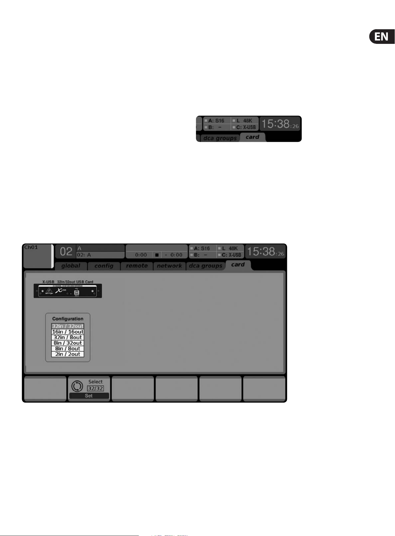
37 X32 DIGITAL MIXER Preliminary User Manual
6. USB Interface Operation Guide
Host system requirements for X-USB interface
expansion card
Check the BEHRINGER website at behringer.com for updates of X-USB rmware
or system requirements. Please nd the recommended hardware/software
minimum congurations in the specications section.
Note - the X32 initially shipped with the X-UF FireWire/USB card installed.
As FireWire has become an increasingly obsolete technology, we have begun
optimizing the X32's interface card to provide the most stable and reliable
performance via USB 2.0 on any system, including new computers that do not have
FireWire ports. Since there is no distinct advantage to using FireWire over USB,
we are condent that this update will not pose a major inconvenience to our users.
The BEHRINGER X-USB High-Performance 32-Channel
24-Bit USB Audio Interface
The X-USB card provides 32 channel, bi-directional audio I/O via USB 2.0 to
Mac or Windows PC. The simultaneous 32-in, 32-out audio channels enable
extremely powerful studio and live applications. You can run virtual live sound
checks or 32-track high-quality studio recordings, whileat the same time
remote operating your DAW via HUI/MackieControl emulation. Thehigh speed
24-bit signal transmission and ultra-low latency ASIO drivers and CoreAudio
compatibility even allow inserting audio plugins on your PC to perform advanced
outboard processing.
6.1 Conguring the X-USB card for use in
theconsole
The console will automatically detect the X-USB card during the regular boot
cycle, and it will display the card’s presence in several instances.
The green square in front of “C: X-USB” indicates that the card is installed and
working properly.
Conguration
After the console has fully booted up, you can access the Setup/Card screen to
view the current channel count conguration. Depending on your application,
you may want to select an option other than the maximum 32 x 32 channel count
to preserve system resources.
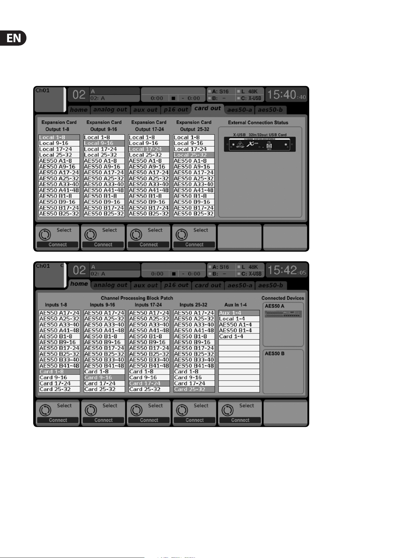
38 X32 DIGITAL MIXER Preliminary User Manual
This mode obviously allows the full potential of the interface to be tapped.
Notethat the computer needs to be able to handle that amount of concurrent I/O
stream without any glitches. Depending on its speed and memory conguration,
someoptimization for audio recording might be required.
It is also possible to run a virtual sound check of all 32 input channels by recording
them directly to a computer during a brief line check. The performers can leave
the stage while you play back the recorded instruments from the hard drive and
tweak the sound accordingly.
32 in / 32 out
Generally, the Card outputs may use any of the available signal sources in the
console (local or AES50) for recording independently. When the X32 console is
used in a quasi in-line mode, the card with connected computer represents a
classic tape machine. In this case, the X32 console mic inputs would be selected
to feed the card outputs (see graphic), and all signals are run from the mixer’s
preamps directly to the multi-track recording machine (PC) and from there 1:1
back into the console’s input channels.
When the console channel inputs are set to Card, the channel Gain control will be a
+/- 12 dB digital trim for the interface card signal, without direct access to any head
amp - which is great for mixdown but would be an issue for recording. So, mixing
and monitoring can be done using the X32 input channel controls, but the actual
mic preamps must now be controlled from the Setup/preamps page, which gives
remote control to every one of the available preamps in the system. Use the Setup/
preamps page to make sure that phantom power is set as needed, and that there is
a reasonable amount of headroom for recording the preamp signals.
TIP: Sometimes it is more convenient to run the sound check while the preamps
are still connected to the X32 input channels. Once you are condent about the
fundamental settings, you can switch the channel inputs to the X-USB Card
inputs for laying the tracks and monitoring the DAW outputs.
If you wish to switch back and forth between the two modes more frequently,
you could consider storing 2 routing scenes, ’DAW’ and ’preamps’. Make sure
Scene Safes are set in a way that all other parameters remain unchanged.
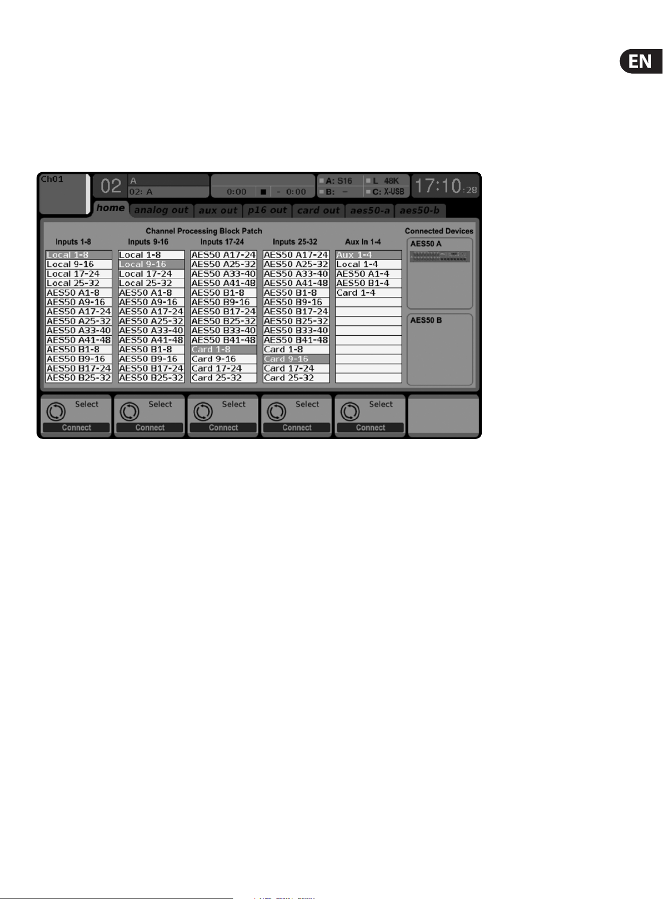
39 X32 DIGITAL MIXER Preliminary User Manual
32 in / 8 out
This mode is tailored to suit a typical studio and overdub recording situation,
withmany input channels but only a few output channels for monitoring of
previously recorded takes.
8 in / 8 out and 2 in / 2 out
For very small recording sessions or overdubs with single sources like vocals,
reducing the channel I/O frees up more processing power and ensures stable
operation with small latency settings.
8 in / 32 out
This is a useful mode for utilizing the excellent audio engine and eects
processing of the console during nal mixdown of your project. All 32 tracks
would be fed from your DAW into the console where all the magic happens.
Thenonly 2-8 tracks of the complete mixdown would be sent back to the DAW.
16 in / 16 out
If you don’t actually need more than 16 concurrent input and output tracks to
be exchanged between the console and your PC, then this mode might be more
appropriate for you. First, it will slow the required bandwidth on the interface
down. Second, there will be no excessive I/O tracks in your DAW conguration
that might clutter your setup. Third, it allows you to run a fully-featured
zero-latency overdub setup, which would be impossible if signals were run
through the computer. In this case, the 16 input signals are put on channels
1-16, whilethe tape (card) returns are put on channels 17-32. The monitoring is
directly fed from Ch1-16 as usual, including all processing and eects. It remains
independent from any computer audio latency, even though you can hear back all
the recorded tracks without any repatching.
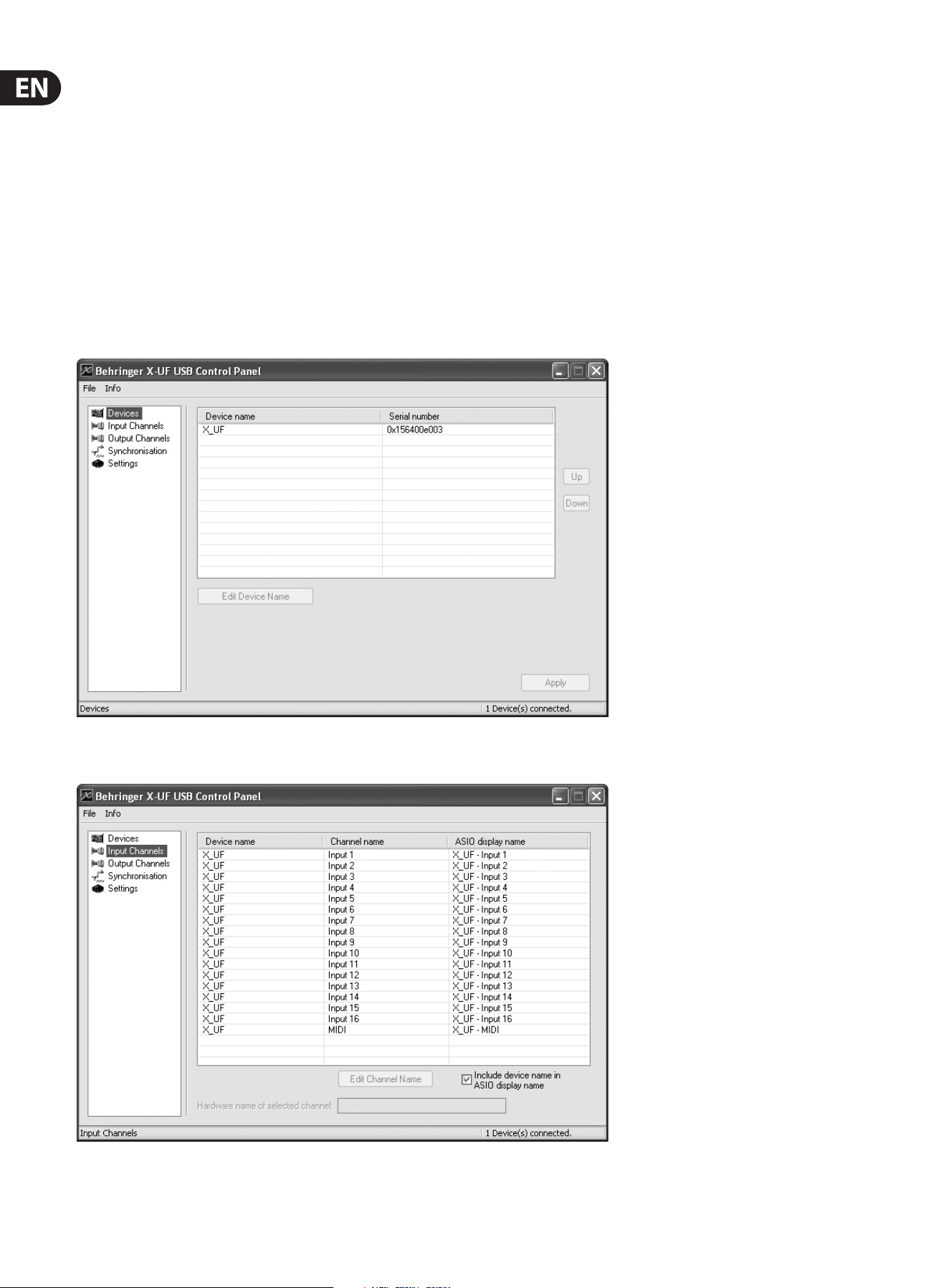
40 X32 DIGITAL MIXER Preliminary User Manual
6.2 Conguring the PC to Interface
withtheX-USB Card
Please watch behringer.com for further advice on the software conguration of
X-USB interface card.
Windows: There is an ASIO high-performance driver available for
download, which is essential for low-latency audio on
Windows computers.
MacOS: The X-USB is CoreAudio compatible and thus works with
low-latency on Mac computers without any additional
driverinstallation.
Windows ASIO Driver
Download the X32 ASIO driver installer les from behringer.com. Double-click on
Setup.exe in the corresponding unpacked folder and follow the instructions on
the screen.
Driver Control Panels
Once the driver is installed, you can open the control panel by double-clicking
on the small tray icon. These screens will allow conguring the X-USB expansion
card in the X32 as an audio interface for your computer.
The ’Devices’ screen displays the card name and serial number. You can rename
the card if necessary.
The ’Input Channels’ screen allows you to name each input channel for more
organized mixing.
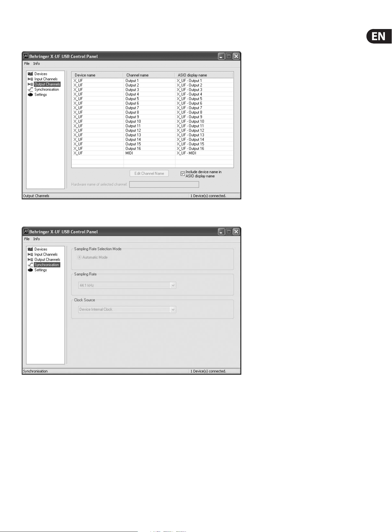
41 X32 DIGITAL MIXER Preliminary User Manual
The ’Output Channels’ screen allows you to name each output channel for more
organized mixing.
The ’Synchronisation’ screen allows manual selection of the sample rate and
clocksource.
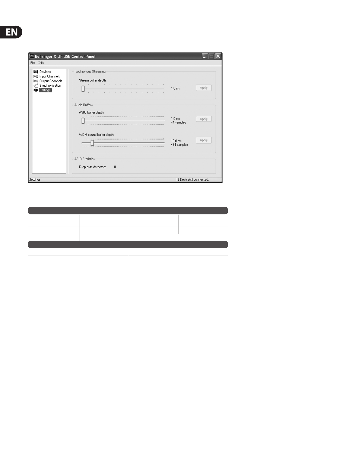
42 X32 DIGITAL MIXER Preliminary User Manual
The ’Settings’ screen allows the stream, ASIO, and WDM sound buers to be set.
Any detected drop outs will be documented as well, in which case a larger buer
should be selected.
6.3 X-USB Specications
* depends on system performance and application
Expansion Card Features:
Interface MIDI
Audio input channels
24-Bit, 44.1/48 kHz
Audio output channels
24-Bit, 44.1/48 kHz
HighSpeed USB 2.0 1 in x 1 out 32, 16, 8 or 2 32, 16, 8 or 2
DAW remote control Generic, HUI and Mackie Control emulation
Expansion Card Performance:
Interface Typical round-trip latency
HighSpeed USB 2.0 ~14 ms
Recommended Minimum Hardware:
Windows PC - Core 2 Duo CPU, 2 GHz
- USB 2.0 port
- 1 GB RAM
Mac - 1.5 GHz CPU
- USB 2.0 port
- 512 MB RAM
Recommended Operating Systems:
Windows: XP 32-Bit SP2 or higher, Win7 32-bit, Win7 64-bit ,
Win8 64-bit (X-USBASIO drivers supplied)
MacOSX: 10.5 Leopard, 10.6 Snow Leopard,
10.7 Lion
10.8 Mountain Lion
(CoreAudio compatible)

43 X32 DIGITAL MIXER Preliminary User Manual
7. X32 Main Display
7.1 Overview
7.1.1 Display and Navigation Controls
The controls in this section are used in conjunction with the color screen, in order
to navigate and control the graphical elements it contains.
By including dedicated rotary controllers that correspond to adjacent controls on
the screen, as well as including cursor buttons, the user can quickly navigate and
control all of the color screen’s elements.
Color Screen: This color screen contains various displays that give visual
feedback for the operation of the console, and also allow the user to make various
adjustments not provided for by the dedicated hardware controls.
Rotary Encoders: These six rotary encoders are used to adjust various color
screen elements located directly above them. Each of the six rotary encoders
can be pushed inward to activate a button press function. This function is useful
when controlling color screen elements that have a dual “on/o” type state that
is best controlled by a button, as opposed to a variable state that is best adjusted
by a rotary control.
Screen selection buttons: These 8 illuminated buttons allow the user to
immediately navigate to any of 8 master screens that address dierent sections
of the console. The 8 sections that can be navigated to with these buttons are:
1. Home
2. Meters
3. Routing
4. Setup
5. Library
6. Eects
7. Mute Group
8. Utility
Page Select Buttons: These two buttons allow for left-right navigation among
the dierent “pages” contained within a screen set. A graphical tab display shows
which page you are currently on.
Layer Up/Down Buttons: On some screens, there are more parameters present
than can be adjusted by the 6 encoders underneath. In these cases, use the layer
up/down buttons to navigate through any additional layers contained on the
screen page.
L/R Meter: This dual 24-segment meter displays the audio signal level output
from the main bus of the console.
M/C SOLO Meter: This dual 24-segment meter displays the audio signal level
output from the mono bus of the console. When one or more channels are
currently soloed, the meter switches to displaying the level of the currently
soloed signal(s).
7.1. 2 Console Screens
The color screen of the X32 oers a wealth of visual feedback and hands
on control for the console. Whereas the dedicated top panel controls oer
immediate hands-on adjustments for the most important operations of a
channel, the color screens oer similarly immediate visual feedback for a selected
channel, as well as more global areas of the console.
The screens are divided into three main areas:
1. Global Screen Elements
2. Main Display
3. Rotary Encoder Elements
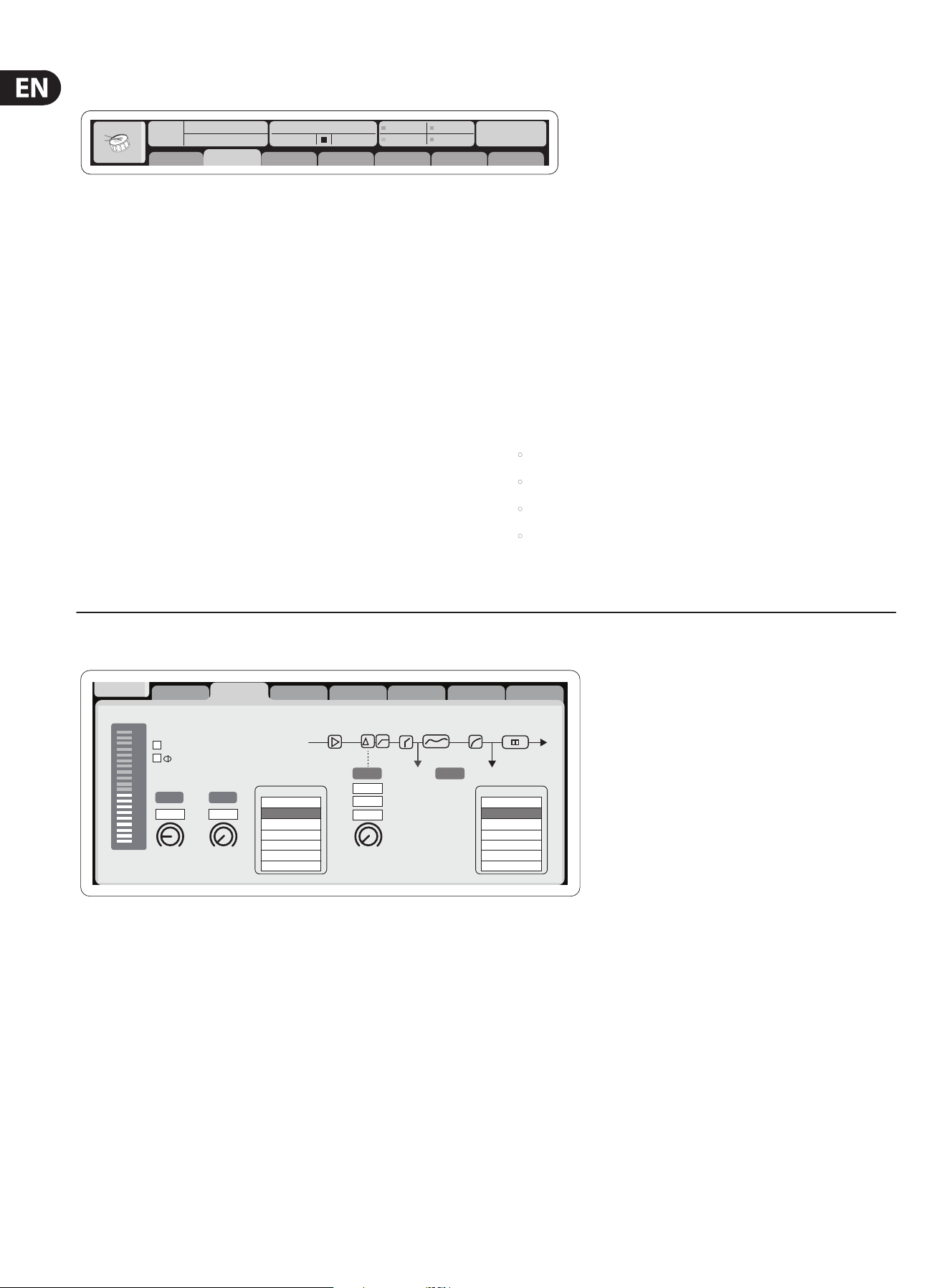
44 X32 DIGITAL MIXER Preliminary User Manual
Main Content
Link Lo Cut
01:
01
0:00 - 0:00
B: - C: XUF
: 37
14:11
-6
-12
-18
-24
-30
-36
-42
-48
-54
clip
home gate dyn eq sends main
cong
Gain
Gain
48V
In
Pre PostIns
Delay
Lo Cut
Lo Cut
Source Ins Pos InsertDelay
Delay
dB
+0.0
Hz
2.0
Reverse
t
ft
m
ms
0.3
0.10
0.03
Source
OFF
Input 01
Input 02
Input 03
Input 04
Input 05
Input 06
Insert
OFF
InsFX 1L
InsFX 1R
InsFX 2L
InsFX 2R
InsFX 3L
InsFX 3L
Insert Position
The main content of the screen is displayed in the middle of the screen and is
divided up into dierent sections of information, depending on the specic
screen being shown at any given time.
Information shown in the main content portion of the screen consists of
twotypes:
1. Display-only content: This type of content is a visual indication only and
cannot be adjusted by the user. An example would be the graphical response
curve of an equalizer or the response graph of a compressor.
2. Adjustable content: Content that displays an adjustable parameter,
controlled by a dedicated top-panel control. For example, the “home” tab of
the “home” screen displays a knob graphic for input gain (trim). This control
is adjustable by turning the dedicated “gain” control on the top panel of the
console, in the Channel Strip section of the top panel.
The most important information for any screen category will be located on it’s
“home” page. However, most screens contain alternate pages of information that
are also useful. They are represented by dierent “tabs” that can be seen towards
the top of the screen. Each tab is named to describe the functions it represents.
Navigate to these alternate tabs by pressing the Page Select left and right keys.
Global Screen Elements
Ch01
FatSnare
OpeningScene
02: next 0:00 - 0:00
A: S16 A: 48K
B: - C: X-USB
: 15
01 15:33
home
cong
gate dyn eq sends main
The “global” screen elements are located at the top of the screen, laid out in a
horizontal row. They always remain visible no matter what specic screen the
user has currently navigated to, because they displays console parameters that
are always important to keep in view at all times.
These screen elements include, from left to right:
Channel Indicator: Displays various elements of the currently
selected,including:
1. The number of the specic input or output channel that is currently selected
2. The custom channel name (if one has been assigned)
3. Channel color (if one has been assigned)
4. Channel icon (if one has been assigned)
Show Indicator: This number, presented in a large orange colored font,
displaysthe currently loaded show.
Scene Name/Number: Thus number, displayed in a smaller black colored font,
indicates the number of the currently loaded scene.
USB Recorder File: Displays the name of the active le that is currently being
recorded or played back.
AES50-A: Displays, by name, what AES50 based equipment is connected to the
console’s AES50-A port. The green LED lights solid when a valid AES50 connection
is present.
AES50-B: Displays, by name, what AES50 based equipment is connected to the
console’s AES50-B port. The green LED lights solid when a valid AES50 connection
is present.
Word Clock/Sample Rate Indicator:
1. Displays the current sample rate of the console.
2. The green LED illuminates when a valid internal or external clock is present.
3. Displays the current source of the clock:
• L: Internal Clock
• A: AES50 port A
• B: AES50 port B
• C: X-USB
Clock: Displays the current time of day in hours:minutes:seconds.

45 X32 DIGITAL MIXER Preliminary User Manual
7.1. 3 Navigation Methods
Following is an overview of how to navigate to the dierent console screens,
screen tabs, and sets of encoder parameters.
1. Press any of the assorted “View” buttons on any section of the console
top panel to switch the screen to the content that is tied to those
hardwarecontrols.
2. Alternatively, press any of the eight hardware buttons located to the right-
hand side of the screen to switch the screen to eight other areas that are not
covered by the assorted “View” buttons.
3. On any given screen, press the Page Select left/right keys to navigate among
the various screen “tabs” within a screen category.
4. On any given screen, press the Layer up/down keys to navigate among the
various sets of encoder parameters located at the bottom of each screen.
Dedicated Screens
The eight screens described in the following section are all “dedicated” screens.
They are accessed by pressing one of the eight dedicated buttons located to the
right of the screen itself. This is in contrast to the “View” based screens, whichare
navigated to by pressing the “View” button in various sections of the console
toppanel.
Rotary Encoder Elements:
Gain
dB
+0.00
Link
Lo Cut
Hz
20
Lo Cut
Input
Select
Source
PRE
Insert
Ins Pos
InsF
Connect
Insert
ms
0.3
Delay
Delay
The bottom of most screens contain 6 slots of information that are always paired
with the 6 hardware rotary encoders located directly underneath each slot.
Thehardware encoders are used to adjust parameters displayed in these slots,
and operate in the following manner:
1. Parameters displayed in the top half of each slot are most often “continuous”
type parameters, and are adjusted by rotating the corresponding encoder
located directly below the bottom of the screen.
• For example, in the “home” tab of the Home screen, the “gain”
parameter of the selected input (located in slot 1) is adjusted with the
rst encoder.
2. Parameters displayed in the bottom half of each slot (outlined in dark grey)
are most often “on/o” style parameters, and are adjusted by pushing the
encoder inward, using it as a button.
• For example, in the “home” tab of the Home screen, the “link”
parameter of the selected input (located in slot 1) is adjusted with the
rst encoder’s push action.
3. If a given screen contains more parameters than ts into the 6 slots, thena
2nd set of slots is made available. Navigate to the next set of slots by
pressing the Layer down key, and the bottom-of-screen content will change
to display the next set of 12 parameters to be adjusted. Press the Layer up
key to return to the original set of 12 parameters.

46 X32 DIGITAL MIXER Preliminary User Manual
7. 2 Home Screen
The home screen contains a high-level overview of the selected input or output
channel, and oers various adjustments not available through the dedicated
top-panel controls:
The home screen contains the following separate tabs:
1. Home: General signal path for the selected input or output channel
2. Cong: Allows selection of signal source/destination for the channel,
conguration of insert point, and other settings
3. Gate: Controls and displays the channel gate eect beyond those oered by
the dedicated top panel controls
4. Dynamics: Controls and displays the channel dynamics eect (compressor)
beyond those oered by the dedicated top panel controls
5. EQ: Controls and displays the channel equalizer eect beyond those oered
by the dedicated top panel controls
6. Sends: Controls and displays for channel sends, such as sends metering and
send muting
7. Main: Controls and displays for the selected channel’s output
7.2 .1 Home Screen: Home Tab
The home tab of the home screen displays a general signal path for the currently
selected input or output channel. It visually displays various parameters of the
input, gate, insert point, equalizer, dynamics, output path, and buses.
The home tab contains the following parameters (divided into two pages)
thatcan be adjusted using the six rotary-push encoders.
Page 1
1. Adjust the 1st encoder to control the input gain (trim) of the channel.
2. Tap the 1st encoder to link the channel with its adjacent channel.
3. Adjust the 2nd encoder to set the threshold of the channel noise gate.
4. Tap the 2nd encoder to toggle the channel noise gate in/out of the
signalpath.
5. Adjust the 3rd encoder to toggle the channel’s insert point between
pre-fader and post-fader status.
6. Tap the 3rd encoder to toggle the channel insert in/out of the signal path.
7. Adjust the 4th encoder to toggle the channel dynamics between pre-EQ and
post-EQ status.
8. Tap the 4th encoder to toggle the channel EQ in/out of the signal path.
9. Adjust the 5th encoder to set the threshold of the channel compressor.
10. Tap the 5th encoder to toggle the channel compressor in/out of the
signalpath.
11. Adjust the 6th encoder to pan the selected channel within the main
stereooutput.
12. Tap the 6th encoder to assign the selected channel to the main
stereooutput.
Page 2
1. Adjust the 1st encoder to select the console channel currently controlled by
the home screen.
2. Tap the 1st encoder to toggle +48V phantom power on/o for the currently
selected input.
3. Tap the 2nd encoder to toggle phase ip on/o for the currently
selectedchannel.
4. Adjust the 3rd encoder to select which of the 8 DCA groups the currently
selected channel will be assigned to.
5. Tap the 3rd encoder to assign the currently selected channel to the selected
DCA group.
6. Adjust the 4th encoder to select which of the 6 mute groups to assign the
currently selected channel to.
7. Tap the 4th encoder to assign the currently selected channel to the selected
mute group.
8. Tap the 5th encoder to toggles solo on/o for the currently selected channel.
9. Adjust the 6th encoder to adjust the fader level for the currently
selectedchannel.
10. Tap the 6th encoder to toggle mute on/o for the currently selected channel.

47 X32 DIGITAL MIXER Preliminary User Manual
7.2.2 Home Screen: Cong Tab
The conguration tab allows selection of signal source/destination for the
channel, conguration of insert point, and other settings, as well as conguration
of the channel delay.
The cong tab contains the following parameters that can be adjusted using the
six rotary-push encoders:
1. Adjust the 1st encoder to control the input gain (trim) of the channel.
2. Tap the 1st encoder to allow linking of the channel with adjacent channel.
3. Adjust the 2nd encoder to set the low-cut frequency of the channel.
4. Tap the 2nd encoder to toggle the low-cut lter in/out of the signal path.
5. Adjust the 3rd encoder to scroll among all of the possible sources for
thechannel.
6. Tap the 3rd encoder to select the currently highlighted source and assign it
to the channel.
7. Adjust the 4th encoder to set the amount of digital line delay applied to
thechannel.
*Note – this is not an echo eect
8. Tap the 4th encoder to toggle the delay in/out of the signal path.
9. Adjust the 5th encoder to toggle the channel insert between pre and post
EQ/compressor.
10. Tap the 5th encoder to toggle the channel insert in/out of the signal path.
11. Adjust the 6th encoder to scroll among the signal path choices for the
insertpoint.
12. Tap the 6th encoder to assign the selected signal path to the insert point.
7.2 . 3 Home Screen: Gate Tab
The gate tab displays all aspects of the channel noise gate and allows for very
deep control of the gate eect. Whereas the top panel’s dedicated gate section
allows control of the gate’s threshold and in/out status, the gate tab oers many
more controls. This tab can also be accessed directly by pressing the “View”
button in the top panel Gate section.
The gate tab contains the following parameters, divided among two pages,
thatcan be adjusted using the six rotary-push encoders:
Page 1
1. Adjust the 1st encoder to set the input threshold of the gate.
2. Tap the 1st encoder to toggle the noise gate in/out of the signal path.
3. Adjust the 2nd encoder to select between a gate, ducker, or 3 types
of expander.
4. Adjust the 3rd encoder to set the attack time of the onset of the noise
gateeect.
5. Adjust the 4th encoder to set the hold time of the noise gate eect.
6. Adjust the 5th encoder to set the release time of the noise gate,
controllinghow quickly the gate opens up and lets the signal through.
7. Adjust the 6th encoder to determine the range of signal reduction.
Page 2
1. Encoders 1 and 2 function the same on pages 1 and 2.
2. Adjust the 4th encoder to set the frequency of the key lter that can be used
to trigger the noise gate.
3. Tap the 4th encoder to toggle the key lter on/o, allowing a specic
frequency to control the gate.
4. Adjust the 5th encoder to set the steepness of the EQ slope used in the
keylter.
5. Tap the 5th encoder to send the key source to the solo bus, allowing the key
source to be monitored and evaluated.
6. Adjust the 6th encoder to select the specic key source to be used.
Choicesinclude “self” (the channel’s own signal) as well as any other
input/output of the console.
7. Tap the 6th encoder to assign the selected key source to the gate.

48 X32 DIGITAL MIXER Preliminary User Manual
7.2 . 4 Home Screen: Dynamics Tab
The dynamics tab displays all aspects of the channel compressor and allows for
very deep control of the eect. Whereas the top panel’s dedicated compressor
section allows control of the threshold and in/out status, the compressor tab
oers many more controls. This tab can also be accessed directly by pressing the
“View” button in the top panel Dynamics section.
The dynamics tab contains the following parameters that can be adjusted using
the six rotary-push encoders:
Page 1
1. Adjust the 1st encoder to set the input threshold of the compressor.
2. Tap the 1st encoder to toggle the compressor in/out of the signal path.
3. Adjust the 2nd encoder to set the ratio of the compressor.
4. Tap the 2nd encoder to switch the channel dynamics eect between
compression and expansion.
5. Adjust the 3rd encoder to set the attack time of the compressor eect.
6. Tap the 3rd encoder to switch the compressor between Peak and RMS
(root-mean-squared) mode, where the average level of the signal is
evaluated more than any specic peak of the channel material.
• PEAK: A peak sensing compressor responds to the instantaneous level
of the input signal. While providing tighter peak control, peaksensing
might yield very quick changes in gain reduction, more evident
compression, or sometimes even distortion. This mode is very suitable
for control/limiting of dynamic material.
• RMS: In this mode, the compressor applies an averaging function on the
input signal before its level is compared to the threshold. Thisallows
a more relaxed compression that also more closely relates to our
perception of loudness. Sharp dynamic transients will be less aected in
this mode. This mode is good for controlling levels in a mix.
7. Adjust the 4th encoder to adjust the “hold” time of the compressor.
• “Hold” time is a parameter not often found on commercial units, but is
very handy. If a compressor is set to use a very fast attack/release time,
audible distortion can occur, because the compressor is trying to work
on individual waveform cycles of the signal instead of sound envelope
as a whole. The “hold” parameter works around this issue by providing
a short delay. This delay prevents the compressor from releasing until a
certain time has passed.
8. Tap the 4th encoder to switch between Linear and Logarithmic modes for the
compressor. Following are some brief denitions of these dierent modes:
• LOG: This mode is used in many well-respected compressors and is the
natural result of more recent analogue units employing logarithmic
side chains and resistor/capacitor time constants. The exponential/
dB law has some interesting characteristics. Firstly, the time taken to
complete a compression event tends to stay the same however large
the dynamic signal excursion is. Also, since the peak rate of gain change
increases with dynamic excursion, the resulting harmonic content due
to compression tends to follow the loudness of the program in a way
the ear expects. This helps to mask the eects of the compression and
thus provides the most forgiving solution, being tolerant to diering
timing settings and program material. This makes it the best choice
for general compression use and overall dynamic control of complex
musical program.
• Linear: In this mode, the rate of gain change is constant (as set by the
timing controls). Therefore, the greater the signal dynamic excursion,
the longer the compressor will take to complete a gain change.
Also,since the total time that the compressor spends in attack or decay
is proportional to the size of the gain excursion, the harmonic content
of the compression artifacts will seem to reduce in frequency content.
The louder the signal excursion is. This type of compressor is useful
for generating dynamic sound eects because the sonic character of
the compression is much more aected by time control settings and
program material than the exponential type.
9. Adjust the 5th encoder to set the release time of the compressor.
10. Tap the 5th encoder to engage the “auto” function, which automatically
optimizes advanced parameters such as attack, hold and release.
11. Adjust the 6th encoder to set the makeup gain of the compressor,
usefulwhen the compression eect has reduced the overall signal level of
the channel too much.
Page 2
1. The 1st encoder still engages and adjusts the threshold.
2. Adjust the 2nd encoder to set the mix of the compressor. Normally this
would be set to 100%, but by reducing the mix level, an eect called
‘parallel compression’ can be achieved, allowing some of the signal to pass
through uncompressed.
3. Adjust the 3rd encoder to set the steepness of the compressor “knee”
between ve separate settings. Adjust this control to switch between a
“harder” sounding or more transparent compression eect.
4. Tap the 3rd encoder to move the compressor eect before or after the
equalizer in the channel signal path.
5. Adjust the 4th encoder to set the frequency of the key lter that can be used
to trigger the compressor.
6. Tap the 4th encoder to toggle the key lter on/o, allowing a specic
frequency to control the compressor.
7. Adjust the 5th encoder to set the steepness of the EQ slope used in
thecompressor.
8. Tap the 5th encoder to send the key source to the solo bus, allowing the key
source to be monitored and evaluated.
9. Adjust the 6th encoder to select the specic key source to be used.
Choicesinclude “self” (the channel’s own signal) as well as any other
input/output of the console.
10. Tap the 6th encoder to assign the selected key source to the compressor.

49 X32 DIGITAL MIXER Preliminary User Manual
7.2 . 5 Home Screen: EQ Tab
The EQ tab displays all aspects of the channel equalizer and also displays a
detailed visual graph of the current EQ curve. This tab can also be accessed
directly by pressing the “View” button in the top panel Equalizer section.
1. If the currently selected channel is an input, the channel equalizer contains
four bands, with various aspects of each band adjusted by encoders 2-5.
2. If the currently selected channel is a bus, the channel equalizer contains six
bands, with various aspects of each band adjusted by encoders 1-6.
3. On the EQ screen, the various push encoders are always tied to an aspect
of the frequency adjustment, and the Up/Down navigation controls are
used to toggle between the 4 bands. The 6th encoder also toggles which
band is active.
• Adjust the 1st encoder to set the low cut frequency.
• Tap the 1st encoder to engage the low cut.
• Adjust the 2nd encoder to adjust the frequency for the selected band. All 4
bands can be shifted between 20 Hz and 20 kHz, so the band labeled 'Low'
can actually be used to adjust mids, etc.
• Tap the 2nd encoder to determine whether the RTA operates as a bar graph
or spectrograph.
• Adjust the 3rd encoder to set the amount of cut or boost for the selected
band.
• Tap the 3rd encoder to set the RTA as pre or post, depending if you want to
monitor the incoming signal or the eects of the EQ adjustment.
• Adjust the 4th encoder to set the bandwidth (Q) of the selected band. This is
only available if the band is set to PEQ or VEQ.
• Tap the 4th encoder to reset the selected EQ band.
• Adjust the 5th encoder to determine the mode of the selected band. The
following options are available:
• Low cut
• Low shelf
• PEQ (standard parametric)
• VEQ (vintage style)
• High shelf
• High cut
• Tap the 5th encoder to reset all of the EQ bands.
• Adjust the 6th encoder to select the frequency band.
• Tap the 6th encoder to activate the EQ.
7.2 .6 Home Screen: Sends Tab
The sends tab displays and controls all aspects of the channel sends to the sixteen
mix buses. Compared to the dedicated top panel send controls, this screen
oers additional functions such as send muting and simultaneous metering of
the selected channel’s sixteen sends. This tab can also be accessed directly by
pressing the “View” button in the top panel sends section.
The sends tab contains the following parameters that can be adjusted using the
six rotary-push encoders:
Page 1
1. Adjust the 1st encoder to set the level for the rst send of the currently
selected four-send group.
2. Tap the 1st encoder to mute the rst send of the currently selected
four-sendgroup.
3. Repeat process with the next three encoders for the other three sends in the
currently selected four-send group.
4. Adjust the 6th encoder to select which four sends to control with the screen
encoders, shifting focus two sends at a time.
5. Tap the 6th encoder to select which four sends to control with the screen
encoders, shifting focus four sends at a time.
Page 2
1. Adjust the 1st encoder to select where in the signal chain the send is
tapped from, for the rst two sends of the currently focused four sends.
Optionsinclude:
• Pre-EQ
• Post-EQ
• Pre-Fader
• Post-Fader
• Sub-Group
2. Adjust the 3rd encoder to perform the same operation for the second two
sends of the currently focused four sends.
3. Adjust the 6th encoder to select which four sends to control with the screen
encoders, shifting focus two sends at a time.
4. Tap the 6th encoder to select which four sends to control with the screen
encoders, shifting focus four sends at a time.
7.2 .7 Home Screen: Main Tab
The main tab displays and controls all aspects of the main bus assignments.
The main tab contains the following parameters that can be adjusted using the
six rotary-push encoders:
1. Adjust the 1st encoder to pan the selected channel within the main
stereooutput.
2. Tap the 1st encoder to assign the selected channel to the main stereo output.
3. Adjust the 2nd encoder to adjust the level of the currently selected channel
within the mono (center) bus.
4. Tap the 2nd encoder to assign the selected channel to the mono output
signal path. Use this function when crafting an LCR mix as opposed to a
mono or stereo mix.
5. Tap the 5th encoder to solo/unsolo the currently selected channel.
6. Adjust the 6th encoder to set the fader level for the currently selected channel.
7. Tap the 6th encoder to mute/unmute the currently selected channel.

50 X32 DIGITAL MIXER Preliminary User Manual
7. 3 Meters Screen
The meters screen displays dierent groups of level meters for various signal
paths of the console, and is useful for quickly ascertaining if any channels need
level adjustment. A Real Time Analyzer has also been added for frequency
monitoring of various sources.
The meter screen contains the following separate screen tabs, each containing
level meters for the following signal paths:
1. Channel:
• Level meters and fader levels for the 32 input channels
• Gate response meters for the 16 input channels
• Gain reduction meters for the 16 input channels
2. Mix Bus:
• Level meters, fader levels, and gain reduction meters for the
16busmasters
• Level meters, fader levels, and gain reduction meters for the
6matrixoutputs
• Level meters, fader levels, and gain reduction meters for the stereo
main bus and the mono bus
3. Aux/FX:
• Level meters for the 6 auxiliary sends
• Level meters and fader levels for the 8 auxiliary returns
• Level meters and fader levels for the 4 stereo eects returns
4. In/Out:
• The 32 input channels
• The 8 auxiliary returns
• The 6 auxiliary sends
• The two rear panel digital outputs
• Monitor outputs
• The 16 rear panel analog outputs
• The P16 Ultranet outputs
5. RTA:
The Real Time Analyzer provides accurate feedback of source frequencies in either
bargraph or spectrograph form, allowing problematic or feedback frequencies to
be quickly identied. The frequency information can be viewed on the dedicated
RTA tab, but can also be overlayed on top of the channel parametric EQ or the
31-band EQ in an FX slot. The 6 encoders allow adjustment for all 3 scenarios.
1. Rotate the rst encoder to cycle through the 6 check boxes to select various
designations. Press the encoder to check the box.
Channel EQ Defaults
The channel parametric EQ defaults to post-EQ, allowing you to see the results
of your EQ adjustments in real time on the analyzer. Select the ‘Pre EQ’ box to
monitor the RTA independent of channel adjustments. Select the ‘Spectrograph’
box to view in spectrograph form instead of the default bargraph.
GEQ Defaults
Per default, the 31-band EQ will display the RTA information at the bus in which
the EQ is inserted (for example, Main LR). Select the ‘Use RTA Source’ box to
display the RTA source (see encoder 6). To view the frequencies as they are
adjusted by the EQ, select the 'Post GEQ' box. Select the ‘Spectrograph’ box to
view in spectrograph form instead of the default bargraph.
RTA Source
When the ‘Solo Priority’ box is selected, the RTA source will be replaced with
the monitor solo bus whenever a channel solo is active. This option is useful
for analyzing a group of channels concurrently, or only briey analyzing other
channels than the xed RTA source. This aects both the GEQ RTA view and the
dedicated RTA tab view.
2. Press the 2nd encoder to view the frequencies on the RTA tab as a bargraph
or spectrograph. Note that this does not aect the channel EQ or 31-band EQ
view. The spectrograph view displays frequencies over a 10 second window,
which may make it easier to identify highly dynamic source material.
3. Press the 4th encoder to enable Auto Gain, which is recommended for most
situations to ensure meaningful readings. However, when disabled, the gain
can be manually adjusted with the encoder which may be necessary for
comparing absolute frequency band levels between dierent channels.
4. Adjust the 5th encoder to set the EQ overlay transparency of the analyzer on
top of the channel or 31-band EQ. When set to 0%, the RTA will not be visible
on the EQ screens. Press the encoder to set the source as Pre or Post EQ.
5. Adjust the 6th encoder to select the RTA source. This can be dynamic if you
would like to monitor the currently selected channel or monitor source, or a
xed channel can be selected (for use with a dedicated measurement mic,
for example).

51 X32 DIGITAL MIXER Preliminary User Manual
7.4 Routing Screen
The routing screen is where all signal patching is done, allowing you to route
internal signal paths to and from the physical input/output connectors located on
the console’s rear panel.
The routing screen contains the following separate tabs:
1. Home: Allows patching of physical inputs to the 32 input channels and
Auxinputs of the console.
2. Analog Out: Allows patching of internal signal paths to the console’s
16 rear-panel XLR outputs.
3. Aux Out: Allows patching of internal signal paths to the console’s
6 rear-panel ¼"/RCA auxiliary outputs.
4. P16 Out: Allows patching of internal signal paths to the 16 outputs of the
console’s 16-channel P16 Ultranet output. The iQ speakers can also be set up
from this tab.
5. Card Out: Allows patching of internal signal paths to the 32 outputs of the
XUF card.
6. AES50-A: Allows patching of internal signal paths to the 48 outputs of the
rear panel AES50-A output.
7. AES50-B: Allows patching of internal signal paths to the 48 outputs of the
rear panel AES50-B output.
8. XLR out: Allows patching of internal signal paths to the XLR outputs on the
rear panel.
None of the routing screen’s tabs contains a secondary level of encoder functions.
When routing audio, the Layer up/down keys do not need to be used.
7.4.1 Routing Screen: Home Tab
The routing screen’s home tab allows the user to patch the console’s physical
rear-panel inputs to the 32 input channels and Aux inputs of the console.
As a default, the console maps the console’s 32 rear-panel analog inputs to their
the respective 32 channel inputs that are accessed on input fader layers one
and two, and maps the rear panel line-level (auxiliary) inputs to the third input
faderlayer.
However, the home tab of the routing screen can be used to change this
default assignment and “crosspatch” dierent physical inputs to dierent
channel inputs, in banks of 8 channels at a time. This allows the user to create a
custom layout of channel inputs that diers from the order that the sources are
plugged into the rear panel, and is easier than physically re-patching physical
audiocables.
To assign various inputs to the console’s input channels, perform the
followingsteps:
1. Adjust the rst rotary encoder to select which 8-channel audio input
source feeds input channels 1-8 of the console. As the encoder is rotated,
thecurrently selected input will be highlighted in the vertical list of choices.
2. When the desired 8-channel source is selected, push the 1st encoder to
“connect” the currently selected 8-channel source. The selected source now
feeds input channels 1-8 of the console.
3. Input choices that can be assigned include:
• Local 1-8
• Local 9-16
• Local 17-24
• Local 25-32
• AES50-A 1-8
• AES50-A 9-16
• AES50-A 17-24
• AES50-A 25-32
• AES50-A 33-40
• AES50-A 41-48
• AES50-B 1-8
• AES50-B 9-16
• AES50-B 17-24
• AES50-B 25-32
• AES50-B 33-40
• AES50-B 41-48
• Card 1-8
• Card 9-16
• Card 17-24
• Card 25-32
4. To assign an 8-channel source for the other input channels of the console
(9-16, 17-24, 25-32), simply repeat the process above, usingthe other four
rotary encoders on the same screen.
5. Choices for Aux In 1-4 include:
• Aux 1-4
• Local 1-4
• AES50-A 1-4
• AES50-B 1-4
• Card 1-4

52 X32 DIGITAL MIXER Preliminary User Manual
7.4.2 Routing Screen: Analog Out Tab
The routing screen’s analog out tab allows the user to patch the console’s various
internal signal paths to the 16 analog XLR outputs that are located on the console
rear panel.
The X32 console allows for many dierent kinds of output signal paths, and this
screen is where these output paths are assigned to an actual physical rear panel
output so that the signal path can be patched to their eventual destination
(suchas the front-of-house PA speakers or a powered stage monitor).
To assign the various output paths to the rear panel XLR outputs, perform the
following steps:
1. Adjust the 1st encoder to select which of the 16 rear panel analog outs you
wish to assign an output signal path to.
2. Adjust the 3rd encoder to select an output path “category”.
These categories include:
• O
• Main (LRC) Mix
• Mix Bus Outputs
• Matrix Outputs
• Direct Outs
• Monitor
3. Adjust the 4th encoder to select a specic output path, including:
• O
• Main L
• Main R
• Main C/M
• Any of the 16 Mix Outputs
• Any of the 6 matrix outputs
• Any of the 32 direct outputs
• Any of the 8 Auxiliary Outputs
• Any of the FX Direct Outputs
• Monitor L
• Monitor R
• Talkback
4. Tap the 4th encoder to assign the selected output path,
completing the process.
5. Adjust the 5th encoder to select the signal tap point for the output
assignment. This determines where in the audio signal path the source is
“tapped” as it is sent to the physical rear panel output. The available signal
tap points include:
• Input
• Pre-EQ
• Pre-Fader
• Post-Fader
6. Tap the 5th encoder to assign the selected signal tap point.
7. Adjust the 6th encoder to adjust the amount of digital line delay applied to
the output path as it is sent to the rear-panel physical output. As the amount
of delay is adjusted, the current delay time is displayed in three dierent
units of measurement: Feet, Meters, and Milliseconds.
8. Tap the 6th encoder to toggle delay on/o. The “delay” label illuminates
when the delay is inserted into the signal path.
TIP: Applying a delay to an output signal is typically done when the console is
used in a “multi-zone” P.A. speaker setup, where some PA speakers are located
near the stage and a second set of speakers are located further back within
the audience. By applying an appropriate amount of delay only to the speakers
located further from the stage, the audience hears the audio from the closer/
further speakers at the same time, insuring maximum time-alignment and
sound quality. The console assumes an operating temperature of 20°C/68°F
whencalculating the delay times.
7.4.3 Routing Screen: Aux Out Tab
The route screen’s aux out tab allows the user to patch an internal signal
path (such as a mix output used as an eects send) to the 6 separate ¼"/RCA
auxiliaryoutputs.
Since these six outputs can have a wide variety of signal paths assigned to them,
they can be used for a wide variety of tasks, such as:
1. Feeding an external eects processor when the internal eects
areinsucient
2. Patching a specic console signal path into an outboard recorder
3. Feeding the analog or digital audio inputs of a nearby video recorder
To make an assignment as described above, perform the following steps:
4. Adjust the 1st encoder to select which auxiliary outputs to assign a source
for. Choices include:
• Aux Out 1
• Aux Out 2
• Aux Out 3
• Aux Out 4
• Aux Out 5
• Aux Out 6
• AES/EBU (Digital) Out L
• AES/EBU (Digital) Out R
5. Adjust the 3rd encoder to select for coarse range
• Insert
• Main (LRC)
• Mix Bus
• Matrix
• Direct Out
• Monitor

53 X32 DIGITAL MIXER Preliminary User Manual
6. Adjust 4th encoder to select specic signal path to feed the selected physical
output. Choices include:
• Insert Point
• Main L
• Main R
• Main C/M
• Any of the 16 Mix Outputs
• Any of the 6 matrix outputs
• Any of the 32 direct outputs
• Any of the 8 Auxiliary Outputs
• Any of the FX Direct Outputs
• Monitor L
• Monitor R
• Talkback
7. Tap the 4th encoder to assign the selected output path,
completingtheprocess.
8. Adjust the 5th encoder to select the signal tap point for the output
assignment. Choices include:
• Input
• Pre-EQ
• Pre-Fader
• Post-Fader
9. Tap the 5th encoder to complete the signal tap point assignment.
7.4.4 Routing Screen: P16 Tab
The routing screen’s P16 tab allows the user to route various console signal paths
to the rear panel P16 Ultranet output. The Ultranet output allows for 16 channels
of audio to be sent, in digital form, to various accessories such as a personal
monitoring distribution box.
Using the P16 routing screen, the user can congure the P16 output to carry not
only the main LR mix, but also various audio “stems” of program material sources
from a bus send mix, such as a stereo drum mix, stereo keyboards, guitars,
bass, vocals, etc. Musicians on stage would then be free to each craft their own
personal mix of these musical stems, all delivered from the FOH position to stage
over a single Ethernet cable.
To select which audio signals are sent to the P16 bus, perform the followingsteps:
1. Adjust the 1st encoder to select which of the 16 channels in the P16 bus you
wish to select an audio source for.
2. Adjust the 3rd encoder to select a category of audio source to send to the
currently selected P16 channel. These categories include:
• Insert
• Main (LRC)
• Mix Bus
• Matrix
• Direct Out
• Monitor
3. Adjust the 4th encoder to select which specic signal path to feed to the
currently selected P16 output. Choices include:
• O
• Main L
• Main R
• Main C/M
• Any of the 16 Mix Outputs
• Any of the 6 matrix outputs
• Any of the 32 direct outputs
• Any of the 8 Auxiliary Outputs
• Any of the FX Direct Outputs
• Monitor L
• Monitor R
• Talkback
4. Tap the 4th encoder to assign the selected output path,
completing the process.
5. Adjust the 5th encoder to select the signal tap point for the output assignment.
This determines where in the audio signal path the source is “tapped” as it is
sent to the P16 output. The available signal tap pointsinclude:
• Input
• Pre-EQ
• Pre-Fader
• Post-Fader
6. Tap the 5th encoder to complete the signal tap point assignment.
7. Tap the 6th encoder to enter iQ Setup
• Adjust the 1st encoder to select a P16 channel.
• Adjust the 3rd encoder to select the iQ speaker assigned to the selected
channel. Press the encoder to conrm.
• Adjust the 4th encoder to select an EQ Preset, then press the encoder
to conrm.
• Adjust the 5th encoder to select a Sound Prole that the iQ speaker will
model, then press the encoder to conrm.
• Press the 6th encoder again to return to the P16 tab.

54 X32 DIGITAL MIXER Preliminary User Manual
7.4.5 Routing Screen: Card Output Tab:
The routing screen’s card tab allows the user to patch various signal paths to the
physical inputs and outputs of the X-USB card. The X-USB’s signal path provides
32channels of inputs and 32 channels of outputs. The 32 card inputs can be used
as alternate sources for the two input fader layers, switchable in banks of 8.
To assign an output path to the option card, perform the following steps:
1. Adjust the 1st encoder to select which 8-channel output path to send to the
rst 8 outputs of the card. Choices include:
• Local 1-8
• Local 9-16
• Local 17-24
• Local 25-32
• AES50-A 1-8
• AES50-A 9-16
• AES50-A 17-24
• AES50-A 25-32
• AES50-A 33-40
• AES50-A 41-48
• AES50-B 1-8
• AES50-B 9-16
• AES50-B 17-24
• AES50-B 25-32
• AES50-B 33-40
• AES50-B 41-48
• Card 1-8
• Card 9-16
• Card 17-24
• Card 25-32
• Out 1-8
• Out 9-16
• P16 1-8
• P16 9-16
• Aux 1-6/Mon
2. Tap the 1st encoder to assign the selected output path,
completing the process.
3. Repeat the process with encoders 2-4 to select output paths for the other
24channels of card outputs.
7.4.6 Routing Screen: AES50-A and AES50-B Tabs:
The routing screen’s AES50-A and AES50-B tabs allow the user to patch various
console output paths to the outputs of the dual AES50 connectors. These AES50
connectors can feed other AES50 equipped devices such as a digital stagebox or
standalone multi-track recorder.
The console contains two separate AES50 connectors, an “A” connector and a
“B” connector. These dual connectors allow for an increased level of exibility in
networking the console with various AES50 based equipment.
Each of the two AES50 screens contains the same following sets of parameters
that can be adjusted. To assign various console signal paths to the AES50
connectors, perform the following steps:
1. Adjust the 1st encoder to select an 8-channel signal path that will be sent to
the rst 8 channels of the AES50 connectors output. Choices include:
• Local 1-8
• Local 9-16
• Local 17-24
• Local 25-32
• AES50-A 1-8
• AES50-A 9-16
• AES50-A 17-24
• AES50-A 25-32
• AES50-A 33-40
• AES50-A 41-48
• AES50-B 1-8
• AES50-B 9-16
• AES50-B 17-24
• AES50-B 25-32
• AES50-B 33-40
• AES50-B 41-48
• Card 1-8
• Card 9-16
• Card 17-24
• Card 25-32
• Out 1-8
• Out 9-16
• P16 1-8
• P16 9-16
• Aux 1-6/Mon
2. Tap the 1st encoder to connect the currently selected signal path to the
AES50 pathway.
3. Repeat the above process for the other ve sets of 8-channel AES50 outputs.
The AES50-B tab works exactly the same as the AES50-A screen, but instead
selects sources sent to the output of the console’s AES50-B connector.
7.4.7 Routing Screen: XLR out tab:
The XLR tab allows the rear panel XLR outputs to be reassigned in blocks of 4.
Each encoder can be adjusted to select the desired source, and pressed to conrm
the selection.

55 X32 DIGITAL MIXER Preliminary User Manual
7. 5 Setup Screen
The setup screen oers various controls for global, high-level functions of
the console such as display adjustments, sample rates and synchronization,
usersettings, and network conguration.
The setup screen contains the following separate tabs:
1. Global: This screen oers adjustments for console sample rate and
synchronization, as well as initialization options.
2. Cong: This screen oers adjustments for various global preferences of how
the console operates.
3. Remote: This screen oers dierent controls for setting up the console as a
control surface for various DAW recording software on a connectedcomputer.
4. Network: This screen oers dierent controls for attaching the console to a
standard Ethernet network.
5. Scribble strip: This screen allows a custom color, icon and name to be selected
for each channel which will appear in that channel's scribble strip mini display.
6. Preamps: This screen allows access to various preamp controls.
7. Card: This screen selects between the USB and FireWire connectors, and also
selects the input/output conguration.
7.5.1 Setup Screen: Global Tab:
The setup screen’s global tab allows the user to adjust various global controls of the
console, such as display brightness and contrast, sample rate, and the time and date.
To make adjustments in the global screen, perform the following steps:
1. Adjust the 1st encoder to select from the list of System Controls:
• Shutdown
• Reboot
• Update Firmware
2. Tap the 1st encoder to engage the selected function.
3. Adjust the 2nd encoder to select the sample rate and synchronization.
4. Tap the 2nd encoder to conrm your selection.
5. Adjust the 4th encoder to select an item to initialize.
6. Tap the 4th encoder to initialize your selection.
7. Adjust the 5th encoder to change the currently selected gure for the time
or date.
8. Tap the 5th encoder to scroll through the entries for time and date.
9. Adjust the 6th encoder to change the LCD or LED brightness.
10. Tap the 6th encoder to alternate between LCD and LED brightness.
7.5. 2 Setup Screen: Cong Tab:
The Cong tab allows a variety of global preferences to be selected. All of the
adjustments are made with just 3 encoders.
1. Adjust the 1st encoder to scroll through the list of preferences.
2. Tap the 1st encoder to conrm the selection.
3. Adjust the 4th encoder to scroll through the list of Link and Pan preferences.
4. Tap the 4th encoder to conrm.
5. Adjust the 5th encoder to select a bus pre-conguration scheme. Note that
individual channels and buses can be changed on the Sends screen.
6. Tap the 5th encoder to select the conguration.
7.5.3 Setup Screen: Remote Tab:
The setup screen’s remote tab allows setting up the console as a control surface
for various DAW recording software on a connected computer. With its large
complement of motorized faders, the console can act as an excellent controller
for various DAW software, allowing the user to make level adjustments quickly
and easily without using a mouse.
To adjust the various remote settings, perform the following steps:
1. Tap the 1st encoder to enable the console’s top panel Remote button.
Thisswitches various console hardware, such as the bus faders, tocontrol
computer DAW software instead of the console’s internal audiopath.
2. Adjust the 2nd encoder to select the specic control surface protocol used,
inconjunction with the target DAW software. Choices include:
• Mackie Control: Use this protocol to control any DAW software that is
compatible with a Mackie Control hardware control surface.
• HUI: Use this protocol to control any D.A.W. software that is compatible
with a HUI hardware control surface, such as Pro Tools.
3. Tap the 2nd encoder to assign the currently selected control surface protocol.
4. Adjust the 5th encoder to select whether the remote function uses the MIDI
In and OUT jacks or the X-USB card’s MIDI.
5. Tap the 5th encoder to conrm the selection.
6. Adjust the 6th encoder to adjust various MIDI-based operations for the
console. Choices include:
• MIDI In/Out: This toggles the MIDI input and outputs for the console
on/o.
• Card MIDI: Allows MIDI transmission through the X-USB card.
• USB In/Out: This toggles the console’s USB ports on/o.
• RTP (Real-time Transport Protocol): This toggles on/o the console’s
ability to interface with an Ethernet-based MIDI system.
• Enable MIDI scene recall: This toggles on/o the console’s response to
incoming MIDI messages for switching console scenes.
7. Tap the 6th encoder to toggle the currently selected MIDI option
on/o. Thiscan be useful if you want to ensure that any connected MIDI
transmitters cannot interfere with the console.
7.5. 4 Setup Screen: Network Tab:
The setup screen’s network tab contains settings used when connecting the
console to a standard Ethernet network. The user can set parameters such as
using a xed IP address or having one assigned, as well as setting up the Ethernet
and subnet mask settings.
To set the network address for the console, perform the following steps:
1. Adjust the 1st encoder to select which specic network eld to adjust.
Choices include:
• IP Address
• Subnet Mask
• Gateway
2. Adjust encoders 2, 3, 4, and 5 to set the 4 numerical elds to be adjusted,
forthe selected network eld.
3. Tap the 6th encoder to assign the adjusted settings.
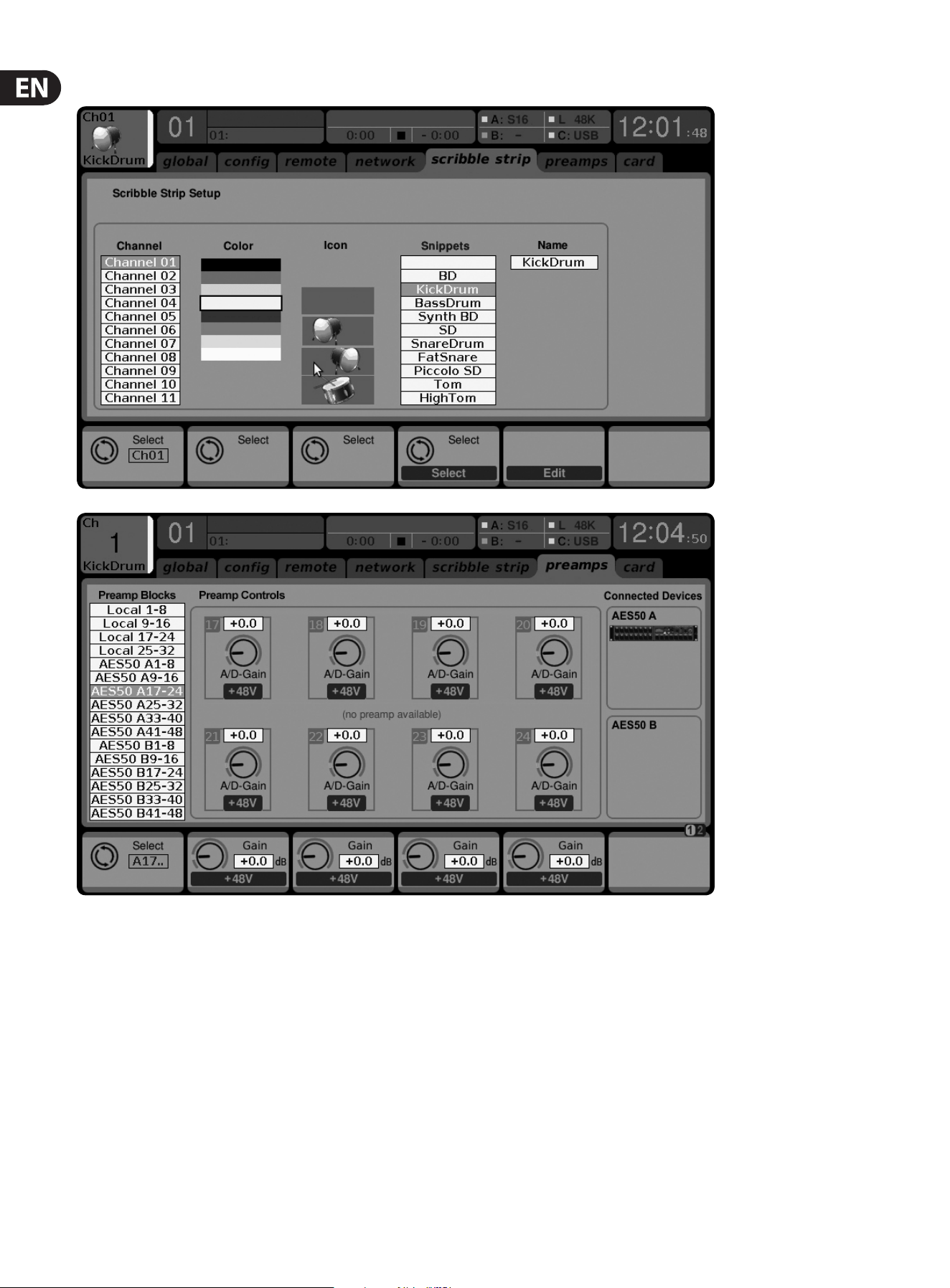
56 X32 DIGITAL MIXER Preliminary User Manual
7.5.5 Setup Screen: Scribble Strip Tab
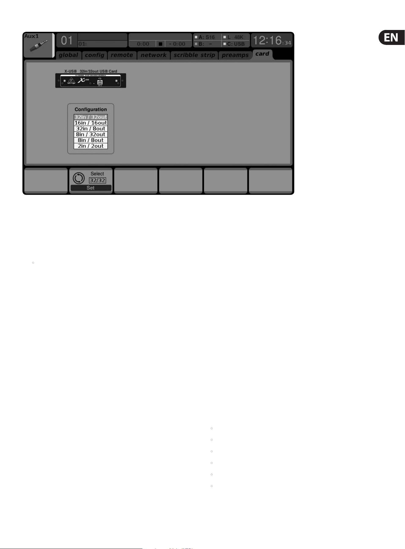
57 X32 DIGITAL MIXER Preliminary User Manual
The Scribble Strip tab allows the color, icon and name that appears in the small
LCD display of a channel, bus, matrix or DCA group to be adjusted.
1. Adjust the 1st encoder to select the channel, bus, matrix, DCA group,
etc. you wish toedit.
2. Adjust the 2nd encoder to set the color for the currently selected channel.
• The selected color will be shown in the LCD screen above the selected
channel’s fader. For example, if DCA#5 is assigned the color red, the LCD
screen above output fader #5 will illuminate in red.
3. Adjust the 3rd encoder to select the graphical icon for the channel. A large
variety of clip-art is available to represent various input sources and
outputdestinations.
4. Adjust the 4th encoder to select a name from a list of common preset names
(snippets), for the currently selected channel.
5. Tap the 4th encoder to assign the currently highlighted preset text (snippet)
to the channel.
6. Tap the 5th encoder to edit the channel name. An edit screen will pop up.
7. Adjust the 4th encoder to shift the cursor position.
8. Tap the 4th encoder to issue a “backspace” command, deleting the currently
highlighted character.
9. Adjust the 5th encoder to select a letter, number, or symbol to enter into the
channel’s name eld.
10. Tap the 5th encoder to insert the currently highlighted letter, number,
orsymbol into the channel’s name eld.
11. Adjust the 6th encoder to select whether the text entry choices oer capitals,
normal characters, or numbers and symbols.
12. Tap the 6th encoder to exit the editing page, and save the current
parameters to the channel.
7.5. 6 Setup Screen: Preamps Tab
The Preamps tab allows the digital trim to be adjusted for all local and
AES50 channels.
1. Adjust the 1st encoder to select a block of 8 channels.
2. Adjust encoders 2-5 to set the preamp gain for the top or bottom
row of inputs.
3. Tap encoders 2-5 to toggle phantom power on and o.
Note - Use the Layer Up and Down buttons to select the top or bottom row of
inputs for editing.
4. Rotate the 6th encoder to select one of 4 checkboxes, then press the encoder
to mark the box and activate that function.
Lock Stagebox prevents front panel adjustments to be made on a connected S16
digital snake.
HA Gain Split separates the channel gain (trim) from the head amp gain, allowing
the FOH console and monitor console to operate their own local digital trims
independently. Note that head amp gains can only be adjusted from the Setup/
preamps page and input channels with have digital trims only.
HA Remote allows console gains to be remote controlled by another console
connected via AES50. This is particularly useful when operating an X32 Rack unit
as a stagebox.
7.5.7 Setup Screen: Card Tab
The Card tab allows selection and conguration of the XUF card. Note that if no
card is installed, this tab is not accessible. Specic routing for the card can be
adjusted on the Routing: Home and Card Out tabs.
1. Adjust the 1st encoder to select between the FireWire and USB connectors.
2. Tap the 1st encoder to conrm your selection.
3. Adjust the 2nd encoder to select the conguration that best suits your
application. See the XUF card chapter for more details. Options include:
• 32 in/32 out
• 16 in/16 out
• 32 in/8 out
• 8 in/32 out
• 8 in/8 out
• 2 in/2 out
4. Tap the 2nd encoder to conrm your selection.

58 X32 DIGITAL MIXER Preliminary User Manual
7.6 Libraries Screen
The libraries screen allows loading and saving of commonly used setups for the
channel inputs, eects processors, and routing scenarios.
The libraries screen contains the following separate tabs:
1. Channel: This tab allows the user to load and save commonly used
combinations of the channel DSP eects.
2. Eects: This tab allows the user to load and save commonly used eects
processor presets.
3. Routing: This tab allows the user to load and save commonly used signal
routings they have set up.
7.6.1 Libraries Screen: Channel Tab
The library screen’s channel tab allows you to load and save commonly used
combinations of the channel DSP eects. For example, once you have dialed in
a combination of equalization and compression that works well for a particular
singer, you can save the channel DSP chain as a preset for later recall.
To adjust the various settings on the channel tab, perform the following steps:
1. Adjust the 1st encoder to navigate among which specic elements of
the input channel can be recalled when loading an input channel preset.
Choicesinclude:
• Head Amp (Microphone Preamplier)
• Conguration
• Gate
• Compressor
• Equalizer
• Sends
2. Tap the 1st encoder to turn the currently selected element on/o in the
recalllist.
3. Adjust the 2nd encoder to scroll among a list of input channel presets.
4. Tap the 2nd encoder to load the currently highlighted preset and make it
active on the currently selected console channel.
5. Adjust the 3rd encoder to scroll among a list of channel preset slots to save
the current state of the currently selected console channel.
6. Tap the 3rd encoder to save the currently selected channel’s state, to the
currently selected preset slot.
• When the 3rd encoder is tapped, a preset naming screen appears.
Adjustand tap encoders 4-6 to apply a custom name to the preset
before saving it, then tap the 6th encoder to complete the save process.
7. Tap the 4th encoder to delete a preset from the currently highlighted
presetslot.
7.6. 2 Libraries Screen: Eects Tab
The library screen’s eects tab allows you to load and save presets for the various
onboard eects processors.
To adjust the various settings on the FX tab, perform the following steps:
1. Adjust the 1st encoder to navigate among which of the eight eects slots to
load or save a preset.
• As you navigate among the eight eects slots, the specic eect
processor loaded into each slot will display on the screen as both a name
and icon.
2. To save and load presets, as well as import/export them, follow the same
procedures as detailed in the Libraries Screen: Channel Tab
7.6. 3 Libraries Screen: Routing Tab
The library screen’s routing tab allows you to load and save presets of the
console’s signal routings. This can be useful for repeating specic routing
scenarios that occur over and over on a regular basis, such as when using the
console for a weekly club gig or worship service.
To adjust the various settings on the routing tab, perform the following steps:
1. Adjust the 1st encoder to navigate among which specic console signal paths
will be recalled when loading a routing preset. Choices include:
• Channel Inputs
• Analog Out
• Auxiliary Out
• P16 (Ultranet) Out
• Card Out
• AES50 Out
• XLR Out
2. Tap the 1st encoder to turn the currently selected element on/o in the
recalllist.
3. To save and load presets, as well as import/export them, follow the same
procedures as detailed in the Libraries Screen: Channel Tab.

59 X32 DIGITAL MIXER Preliminary User Manual
7.7 Eects Screen
The eects screen controls various aspects of the eight internal eects
processors. On this screen, the user can select specic types of eects for
the eight internal eects processors, congure their input and output paths,
monitortheir levels, and adjust the various eects parameters.
The home screen contains the following separate tabs:
1. Home: The home screen provides a general overview for all eight eects
processors, displaying what eect has been inserted in each of the eight slots,
as well as displaying input/output paths for each slot and the I/O signal levels.
2. FX1-8: These eight duplicate screens display all relevant data for the eight
separate eects processors, allowing the user to adjust all parameters for
the selected eect.
7.7.1 Eects Screen: Home Tab
The eects screen’s home tab provides a high-level overview of the eight eect
processor slots, giving the user “at-a-glance” feedback on what eects they
have assigned to the slots, the console source and destination for each processor,
andthe input/output levels for each processor.
To make adjustment on the eects screen’s home tab, perform the
followingsteps:
1. Adjust the 1st encoder to select the input source for the currently highlighted
eect block. Signal path choices include:
• Insert Send
• Mix Bus 1-16
2. Tap the 1st encoder to assign the currently selected input source.
3. Adjust the 2nd encoder to select the input source for the right side of the
currently highlighted eect block.
4. Tap the 2nd encoder to assign the currently selected input source.
TIP: To congure an eect as mono input and stereo output, set both input
sources to the same signal path.
5. Tap the 4th and 5th encoders to mute either side of the eect block.
6. Adjust the 5th encoder to scroll among the dierent available audio eects.
Choices include:
7. Tap the 5th encoder to assign the selected eect to the currently highlighted
eects slot.
8. Adjust the 6th encoder to scroll among the eight eects slots, to select one
for editing.
9. Tap the 6th encoder to go to the edit page for the currently highlighted
eects slot.
7.7. 2 Eects Screen: FX 1-8 Tabs:
The eect editor tab allows you to edit the parameters for the specic eect
processor assigned to the corresponding eects slot.
In order to more closely simulate the look and feel of the outboard processors
that are no longer necessary with a digital console, the individual eects
processor screen provides a graphical representation of the eect processor’s real
world physical counterpart. This provides greater ease of use to the user than a
simple text list of parameters.
To make adjustment on the FX screen’s editing tab, perform the following steps:
1. Adjust the six rotary encoders to change the various eect parameters
shown at the bottom of the screen.
2. Use the Layer up/down buttons to switch the rotary encoders to a second
set of parameters for eects that contain more than six adjustable
parameterstotal.
3. When the eect processor has been edited to your satisfaction, push the 6th
encoder to go back to the FX home tab (or simply resume the mixing duties
in general).
4. See the FX Descriptions chapter for details on specic parameters.
TIP: For the Graphic EQ eects, tap the 1st encoder to implement the “Graphic EQ
on Faders” function. This allows you to boost-cut the dierent EQ bands using the
8 console output faders, 8 faders at a time, with the relevant EQ bands displayed
on the channel LCD screens.
7.8 Mute Group Screen
The mute group screen allows for quick assignment and control of the console’s
6mute groups, and oers two separate functions:
1. It mutes the active screen during the process of assigning channels to mute
groups. This ensures that no channels are accidentally muted during the
assignment process during a live performance.
2. It oers an additional interface for muting/unmuting the mute groups in
addition to the dedicated mute group buttons at the bottom of the console.
When activated, the mute screen only covers the bottom portion of the
main display, allowing the middle portion to continue displaying its usual
screencontent.
To assign channels to one of the 6 mute groups, perform the following steps:
1. Press the Mute Group button to switch the main display to the mute
groupsview.
2. Press and hold the desired mute group button (1-6) on the lower right hand
corner of the console.
3. While holding the mute group button, press the select keys of any input or
output channel, on any layer, that you wish to assign to the mute group.
4. When you have assigned all the desired channels to the mute group,
releasethe dedicated mute group button. The individual channel mute
buttons will resume their normal function.
1. Hall Reverb 21. Suboctaver 41. Fair Comp
2. Ambience 22. Delay + Chamber 42. M/S Fair Comp
3. Rich Plate Reverb 23. Chorus + Chamber 43. Dual Fair Comp
4. Room Reverb 24. Flanger + Chamber 44. Leisure Comp
5. Chamber Reverb 25. Delay + Chorus 45. Dual Leisure Comp
6. Plate Reverb 26. Modulation Delay 46. Ultimo Comp
7. Vintage Reverb 27. Dual Graphic EQ 47. Dual Ultimo Comp
8. Vintage Room 28. Stereo Graphic EQ 48. Dual Enhancer
9. Gated Reverb 29. Dual TruEQ 49. Stereo Enhancer
10. Reverse Reverb 30. Stereo TruEQ 50. Dual Exciter
11. Stereo Delay 31. Dual DeEsser 51. Stereo Exciter
12. 3-Tap Delay 32. Stereo DeEsser 52. Stereo Imager
13. Rhythm Delay 33. Stereo Xtec EQ1 53. Edison EX1
14. Stereo Chorus 34. Dual Xtec EQ1 54. Sound Maxer
15. Stereo Flanger 35. Stereo Xtec EQ5 55. Dual Guitar Amp
16. Stereo Phaser 36. Dual Xtec EQ5 56. Stereo Guitar Amp
17. Dimension-C 37. Wave Designer 57. Dual Tube Stage
18. Mood Filter 38. Precision Limiter 58. Stereo Tube Stage
19. Rotary Speaker 39. Combinator 59. Dual Pitch Shifter
20. Tremolo/Panner 40. Dual Combinator 60. Stereo Pitch

60 X32 DIGITAL MIXER Preliminary User Manual
To use the mute groups screen to mute/unmute the groups, perform the
following steps:
1. Tap any of the six encoders to mute the corresponding group, and thus mute
all channels that are assigned to that mute group.
2. Tap the encoder of a currently muted group to “un-mute” the mute group.
3. When nished working with mute groups, tap the Mute Group screen button
to exit the mute groups screen. The entire screen will again display its full set
of controls for whatever page it was previously on.
7.9 Utility Screen
The utility screen is a supplemental screen designed to work in conjunction
with the other screens that may be in view at any particular moment. The utility
screen is never seen by itself, it always exists in the context of another screen.
To reinforce this point, when the utility screen button is pressed, it illuminates at
the same time that another screen button is also illuminated, showing you which
screen it is providing extra utilities for. For most screens, pressing the utility
button simply acts as a shortcut to a page that can be navigated to by other
means. In a few cases, a utility page provides extra utility functions not seen
anywhere else.
The utility button works in the following manner with the other screens on
theconsole:
Channel Preamp Screens: Takes the user directly to the channel tab of the
library screen.
USB Screen: Takes the user directly to the “select folder” tab of the USB screen.
Monitor/Talkback Screens: There are no utility functions for any of the
dierent pages of the monitor screen.
Scenes Page: Provides an interface for copying, pasting, loading, and saving
dierent scenes in the scene list. Adjust and tap the six rotary encoders to
perform these functions.
Custom Screen: There are no utility functions for any of the dierent pages of
the custom screen.
Meters Screen: There are no utility functions for any of the dierent pages of
the meters screen.
Routing Screen: Takes the user directly to the routing tab of the library screen.
Setup Screen: There are no utility functions for any of the dierent pages of the
setup screen.
Library Screen: There are no utility functions for any of the dierent pages of
the library screen.
Eects Screen: Takes the user directly to the eects tab of the library screen.
“View” Based Screens
The screens described in the following sections are all “View” based screens.
Theyare navigated to by pressing the “View” button in various sections of the
console top panel.
7.10 Monitor/Talkback Screens:
The monitor screen is selected by pressing the “View” button of the top panel’s
monitor section, as well as the “View” button of the top panel’s talkback section.
The screen controls various aspects of the console’s solo bus, control room
outputs, and talkback section.
The monitor/talkback screen contains the following separate tabs:
Monitor: This screen controls various solo options, dimming, speaker delay,
andsources for the control room output.
Talkback A: This screen controls various adjustments for the talkback A path
ofconsole.
Talkback B: This screen controls various adjustments for the talkback B path
ofconsole.
Oscillator: This screen oers various controls for the onboard oscillator and how
it is routed throughout the console.
7.10.1 Monitor/Talkback Screen: Monitor Tab:
The monitor tab controls various console options related to the solo bus, aswell
as the console’s control room outputs. These options include various solo
settings, speaker dimming, speaker delay, and selection of sources for the control
room output.
To adjust the various settings on the monitor tab, perform the following steps:
1. Adjust the 1st encoder to change the gain of the monitor signal. This digital
gain stage occurs as a rst preliminary level control, before the top panel’s
analog-based monitor level control. A display above the encoder shows the
currently set gain value in dB.
• A multi-segment level meter is displayed on the color screen to allow for
proper gain staging of the monitor signal.
2. Adjust the 2nd encoder to scroll through the various solo methods
availableto the console when audio is routed to the solo bus.
Availableoptions include:
• Exclusive (Last): In this mode, pressing another solo button disengages
the previous solo.
• Solo Follows Select: When this method is selected, the audio of the
currently selected channel will automatically be sent to the solo bus.
Since a user will often select a channel to adjust its dedicated DSP
controls, this method is useful because the audio of the channel will
now already be feeding the solo bus where it can be monitored with
headphones in a live sound environment.
• Select Follows Solo: When this method is selected, any channel that is
soloed will automatically become the currently selected channel.
• Channel Solo AFL: With this method, the channel and select button do
not have any correlation to each other. When a channel’s solo button
is pressed, its audio is sent to the solo bus in “after-fader listen” mode,
reecting the current level of the channel fader and any channel DSP
that has been applied.

61 X32 DIGITAL MIXER Preliminary User Manual
• Mix Bus AFL/PFL: This toggles the AFL/PFL setting for the mix
buses when they are soloed (as opposed to the soloing of a single
inputchannel).
• DCA Group AFL: This puts the contents of a soloed DCA group into after-
fader listen mode when the solo button is pressed on a DCA channel.
• Use Master Fader: This allows the Main Fader/mute button to control the
solo/mon output.
3. Tap the 2nd encoder to select and assign the currently chosen solo option.
4. Adjust the 3rd encoder to adjust the amount of digital delay that is applied to
the control room signal path. The display on the screen will show the current
amount of delay in feet, meters, and milliseconds.
5. Tap the 3rd encoder to toggle the delay function on/o.
TIP: The delay function is useful for aligning the sound of audio monitored
through headphones or speakers used at the Front-of-House position with audio
that is coming from the stage location.
By delaying the control room audio, it can be brought into alignment with
the slightly delayed audio that has to travel from the stage to the Front of
Houseposition.
6. Adjust the 4th encoder to set the amount of volume reduction that occurs
when the control room bus has its “dim” function enabled. The amount of
volume reduction ranges from -40 dB to 0 dB (no change).
7. Tap the 4th encoder to toggle the dim function on/o.
8. Adjust the 5th encoder to adjust the volume trim for the source currently
feeding the control room bus, allowing it to be level/matched with other
sources. The amount of trim can be adjusted from -20 dB to +20 dB.
9. Tap the 5th encoder to toggle the control room between mono and stereo
operation. This is very useful in a studio context for checking how a mix
sounds when played back on a mono speaker such as a clock radio.
10. Adjust the 6th encoder to select what specic signal source to monitor in the
control room bus. Choices include:
• O (No source)
• LR Bus
• LR + C/M
• LR PFL (pre-fader listen solo bus)
• LR AFL (after-fader listen solo bus)
• Auxiliary returns 5/6
• Auxiliary returns 7/8
11. Tap the 6th encoder to activate the signal source that has been chosen.
7.10. 2 Monitor/Talkback Screen: Talkback Tabs:
The talkback tabs oer various adjustments for the talkback paths of the console,
such as destination of the talkback signal and more.
To adjust the various settings on the Talkback A tab, perform the following steps:
1. The screen displays a multi-segment level meter showing the signal strength
of the talkback signal as it has currently been set. It also displays a multi-
segment gain reduction meter, showing the user how much compression has
been automatically applied to the talkback signal to keep its level even to
the recipient.
2. Tap the 1st encoder to enable the talkback circuit. The internal/external
talkback microphone will now transmit audio to the Talkback A path’s
assigned destination.
3. Tap the 2nd encoder to switch the talkback circuit from the internal talkback
to the external microphone connector. A 2nd tap of the encoder switches the
console back to using the internal talkback microphone.
4. Adjust the 3rd encoder to set the gain of the talkback A signal. This is an
additional gain stage that follows the initial gain stage set by the top panel
Talk Level knob.
5. Tap the 3rd encoder to toggle on/o the talkback circuit’s “auto-dim”
function. This function is useful in a studio setting, and will automatically
dim the control room outputs when the talkback circuit is active.
Thisprevents a feedback loop from occurring between the talkback
microphone and the nearby studio monitors.
6. Adjust the 4th encoder to scroll through the various talkback destinations,
which include:
• Mix Bus 1-16
• LR Bus
• Center/Mono Bus
7. Tap the 4th encoder to activate any talkback destination when it is currently
selected. Multiple talkback destinations can be selected, allowing the
talkback signal to reach many destinations at the same time.
8. Tap the 5th encoder to toggle the dedicated top-panel talkback buttons
between latching and non-latching operation.
9. Adjust the 6th encoder to adjust the brightness of the lamp that is connected
to the console’s top-panel lamp connector.
10. Tap the 6th encoder to toggle the attached lamp on/o.
All controls for the talkback B tab work as described above, but pertain to the
talkback B signal path.

62 X32 DIGITAL MIXER Preliminary User Manual
7.10. 3 Monitor/Talkback Screen: Oscillator Tab:
The oscillator tab oers controls for the console’s onboard oscillator, a very handy
tool that can be used for setting up PA systems and testing various signal ow
paths without the need for a live source feeding a microphone. Settings include
oscillator type, frequency, volume, and routing destinations.
To adjust the various settings on the Oscillator tab, perform the following steps:
1. Adjust the 1st encoder to set the level of the onboard oscillator.
2. Tap the 1st encoder to toggle the onboard oscillator on/o.
• The color screen displays a multi-segment level meter that show the
current level of the oscillator.
3. Adjust the 2nd encoder to set the frequency of the primary
onboardoscillator.
4. Adjust the 3rd encoder to set the frequency of the alternate
onboardoscillator.
5. Tap the 3rd encoder to alternate between the 2 onboard oscillators.
6. Adjust the 4th encoder to select the type of oscillator to be used.
Choicesinclude:
• Sine Wave
• Pink Noise
• White Noise
7. Tap the 4th encoder to engage the selected oscillator type.
8. Adjust the 6th encoder to select a destination for the onboard oscillator.
Choices include:
• Mix Bus 1-16
• Main L Bus
• Main R Bus
• Main L+R Bus
• Main Center/Mono
• Matrix Outputs 1-6
9. Tap the 6th encoder to assign the selected oscillator destination.
7.11 USB Screen
The USB screen controls various aspects of the console’s onboard audio le
player/recorder, allowing the user to record stereo audio to an attached
USBdrive, as well as playback audio les from the drive through the console.
The USB screen contains the following separate tabs:
Home: This screen provides a general overview of the USB record/
playback interface.
Cong: This screen allows conguration of the various parameters associated
with recording to and playback from the USB drive, such as audio paths,
recordfolders, etc.
7.11.1 USB Screen: Home Tab:
The USB screen’s home tab provides a general overview of the recording/playback
process for audio les residing on the attached USB drive. It oers a basic set of
transport controls, as well as metering and a list of les available for playback.
To adjust the various settings on the USB screen’s home tab, perform the
following steps:
1. Tap the 1st encoder to stop playback of the audio le.
2. Tap the 2nd encoder to play back audio from the currently loaded audio le.
3. Tap the 3rd encoder to rewind the audio.
4. Tap the 4th encoder to fast forward the audio.
5. Tap the 5th encoder to record audio from the currently congured audio
path, to the attached USB drive.
6. Rotate the 6th encoder to select an audio track from the currently attached
USB drive.
7. Tap the 6th encoder to begin playback of the selected audio le.
A list of available audio les is displayed on the right hand side of the screen.
When the currently loaded track nishes playback, the next track in the list will
begin playback. This allows assorted audio tracks on the USB drive to be played
back in sequence and used as “break music” during a break in the band’s set.
The USB screen’s home tab also contains the following helpful displays:
• Stereo meter displays for the recorder input level
• Stereo output meters for the playback level of the le currently
playingback
• A list of available tracks on the attached USB drive
7.11.2 USB Screen: Conguration Tab
The conguration tab allows setting up all aspects of the stereo recorder. In this
screen, one can select audio paths to feed to the recorder and adjust the level of
incoming audio.
To adjust the various settings on the USB screen’s conguration tab, perform the
following steps:
1. Tap the 1st encoder to select a folder to save the recorded audio les to.
• A pop-up window appears, displaying all available folders on the
attached drive.
• Rotate the rst encoder to select an available folder.
• Tap the rst encoder to select the currently highlighted folder.
• Tap the 2nd encoder to select the folder and return to the
maininterface.
2. Rotate the 2nd encoder to adjust the input trim for the currently selected
channel of the stereo recorder. A stereo input meter on the left side of the
screen shows the current input level.
3. Tap the 2nd encoder to select the left or right input of the stereo recorder for
further conguration.

63 X32 DIGITAL MIXER Preliminary User Manual
4. Rotate the 3rd encoder to select the category of input to feed to the currently
selected channel of the stereo recorder. Choices include:
• Main (LRC)
• Mix Bus
• Matrix
• Direct Out
• Monitor
5. Rotate the 4th encoder to select the specic signal source to feed the
currently selected channel of the stereo recorder. Choices include:
• Main L
• Main R
• Main C/M
• Any of the 16 Mix Bus Outputs
• Any of the 6 matrix outputs
• Any of the 32 direct outputs
• Direct Outputs Aux 1-8
• Any of the FX Direct Outputs
• Monitor L
• Monitor R
• Talkback
6. Rotate the 5th encoder to select the signal tap point that the selected audio
path is tapped from when feeding currently selected channel of the stereo
recorder. Choices include:
• Pre EQ
• Post EQ
• Pre-Fader
• Post-Fader
7. Tap the 6th encoder to toggle the “playback folder” mode on/o.
• When playback folder mode is OFF, the transport will stop after playing
the currently selected audio le. This is useful for situations like
triggering audio cues or sound eects in a theatrical setting.
• When playback folder mode is ON, the transport will continue playing
back all audio les residing in the currently selected folder one by one.
This is useful for playing back several songs during a break in the main
set, allowing the attached USB drive to act as a source for “break music”.
7.12 Assign Screen
The assing screen allows setup for the 4 user-assignable rotary encoders and
eight user-assignable buttons. Using this screen, the console operator can assign
3 sets of 12 custom controls to be available for adjustment at all times.
The assign screen contains the following separate tabs:
Home: This screen provides a general overview of the 12 assigned controls for all
three control sets at the same time.
Set A: This screen allows assignment of dierent console parameters to the
12custom controls for set A.
Set B: Works as described above but for custom controls set B.
Set C: Works as described above but for custom controls set C.
7.12.1 Assign Screen: Home Tab
The assign screen’s “home” tab provides a visual overview of the 12 assigned
controls for all three sets at the same time.
The home tab oers visual feedback of the controls that have been assigned to
all three sets of custom controls, without having to bank between the three sets
one-by-one or relying on the abbreviated syntax shown in the custom control’s
dedicated LCD displays.
To adjust the various settings on the home tab, perform the following steps:
1. Press the Up and Down arrows to select Set A, B or C. You can also press the
1st encoder to skip to the next set.
2. Rotate encoders 2-5 to adjust the currently-assigned parameters.
3. Tap the 6th encoder to jump to the edit page for the currently selected set.
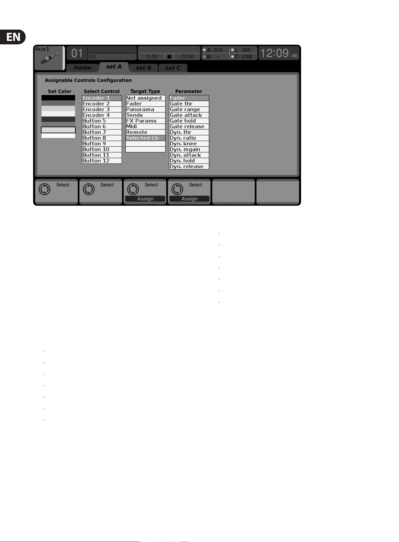
64 X32 DIGITAL MIXER Preliminary User Manual
7.12. 2 Assign Screen: Set A Tab
The “Set A” tab allows mapping of specic console parameters to the 8
assignable buttons and 4 assignable rotary encoders. Using this screen, the
user can map the exact parameters that are most useful to them to the desired
controls, in the desired order.
To adjust the various settings on the set A tab, perform the following steps:
1. Adjust the 1st encoder to select the color used for the LCD screens within
that set.
2. Tap the 1st encoder to invert the text and background color.
3. Adjust the 2nd encoder to select which of the 12 assignable controls in
set A you wish to map a parameter to. Choices include encoders 1-4 and
buttons 5-12.
4. Adjust the 3rd encoder to scroll through a list of parameter categories
that the selected assignable control can be mapped to. Choices for the
buttonsinclude:
• Not Assigned
• Jump to Page
• Mute Channel
• Inserts
• Eect button
• MIDI
• Remote
Choices for the encoders include:
• Not Assigned
• Panorama
• Sends
• Dynamics
• FX Parameters
• MIDI
• Remote
5. Tap the 3rd encoder to assign the selected.
6. Adjust the 4th encoder to scroll through a list of parameters that can be
mapped to the currently selected assignable control.
7. Tap the 4th encoder to assign the selected parameter.
8. Adjust the 5th encoder to select from additional parameters that can be
mapped to the assignable controls.
Assign Screen: Set B Tab and Set C tabs
The Assign screen’s “Set B” and “Set C” tabs works as described above, but are
used to congure the set B and set C controls instead of the set A controls.

65 X32 DIGITAL MIXER Preliminary User Manual
7.13 Scenes Screen
The scenes screen allows setup for saving and recalling dierent memory scenes
of the console. The comprehensive recallability of the console (including gain
settings for the digitally controlled mic preamps) is one of the most powerful
aspects of the console.
The scenes screen contains the following separate tabs:
Home: This screen contains a general overview of the scenes contained in the
console, along with their custom names and what parameters are included in
each scene.
MIDI: This screen allows the console to associate dierent scenes with incoming
and outgoing MIDI messages, allowing the console’s scene changes to control or
be controlled by external MIDI equipment.
Parameter Safe: This screen congures which console parameters are and are
not saved/switched with the console scenes.
Channel Safe: This screen congures which console channels are and are not
changed when a console scene change occurs.
7.13.1 Scenes Screen: Home Tab
The scenes screen’s home tab shows a general overview of the scenes that
have been congured in the console, along with their custom names and what
parameters are included in each scene.
For a setting where scenes are used heavily and are very critical (such as a theater
performance), this would be a good screen to leave on at all times so that the
console operator can be completely sure, at all times, what scene the console
currently resides on and what scene will come up next when the “Go” button
ispressed.
To adjust the various settings on the home tab, perform the following steps:
1. Rotate the 1st encoder to scroll among the available scenes in the scenes list,
which is displayed on the left side of the color screen.
2. Tap the 1st encoder to “go” to the currently selected scene in the list,
switching the console to the state it was in when that scene was stored
3. Rotate the 2nd encoder to select a scene in the list to be “skipped”
whencycling through scenes using the Prev and Next buttons.
4. Tap the 2nd encoder to complete the “skip” command on the currently
selected scene. That scene will now be skipped when scrolling through
thelist.
5. Rotate the 3rd encoder to add a Cue to the list, and determine if it will be
added as a completely new entry, or a subset of an existing cue. Tap the
encoder to bring up the edit screen where the cue can be named.
6. Rotate the 4th encoder to scroll through the list of scenes and tap the
encoder to select.
7. Rotate the 5th encoder to scroll through the list of snippets and tap the
encoder to select.
8. Tap the 6th encoder to undo.
7.13. 2 Scenes Screen: Scenes Tab
The scenes tab allows scenes to be saved, edited and loaded.
1. Rotate the 1st encoder to select a saved scene and tap the encoder to load.
2. Rotate the 2nd encoder to select a scene slot and press the encoder to bring
up the save screen where a name and note can be entered.
3. Rotate the 3rd encoder to select a scene to edit, then tap the encoder to
bring up the edit screen.
4. Tap the 4th encoder to import settings from an attached USB drive.
5. Tap the 5th encoder to save settings to an attached USB drive.
6. Rotate the 6th encoder to scroll through the list of scene safes, tapping the
encoder on each box that you wish to omit from the saved scene.
7.13. 3 Scenes Screen: Snippets Tab
The snippets tab allows specic bits of information to be saved,
edited and loaded.
1. Rotate the 1st encoder to scroll through the list of snippets, then tap the
encoder to load.
2. Rotate the 2nd encoder to scroll through the snippet slots and tap the
encoder to bring up the save screen.
3. Rotate encoders 3-6 to scroll through the list of inputs, outputs and specic
information to be saved, tapping the encoder to check the boxes.

66 X32 DIGITAL MIXER Preliminary User Manual
7.13. 4 Scenes Screen: Parameter Safe Tab
The scenes screen’s “parameter safe” tab congures which console parameters
are and are not saved/switched with the console scenes. This is very useful
when the operator has certain parameters that they wish to remain in control
of, andwould never want to have altered during a scene change, for example,
themic pre gains on the input channels.
To adjust the various settings on the Parameter Safe tab, perform the
followingsteps:
1. Rotate any of the rst 4 encoders to navigate among the checkboxes in the
color screen, which represent various console areas that can be isolated from
scene changes.
2. Tap any of the rst 4 encoders to select the console areas that have been
selected with the encoders. In each of the four columns, multiple console
areas can be selected and isolated from scene changes.
The following areas of the console can be isolated from scene changes, and are
divided up into 4 columns on the color screen:
Column 1: Input Channels
• HA (Head Amp/Microphone Preamp)
• Conguration
• Channel Equalizer
• Channel Gate/Compressor
• Channel Insert
• Channel Groups
• Fader, Pan, Mute, Mix Ons
Column 2: Input Channels
• Mix sends 1-16
Column 3: Mix Buses
• Mix sends 1-16
• Conguration
• Equalizer
• Compressor
• Insert
• Groups
• Fader, Pan, Mute, Matrix Ons
Column 4: Console
• Conguration
• Solo
• Routing
• Output Patch
7.13. 5 Scenes Screen: Channel Safe Tab
The scenes screen’s “channel safe” tab congures which console channels are
and are not changed when a console scene change occurs. This allows the
user to “protect” certain channels from ever changing during a scene change,
givingthem as much control as possible for key audio sources.
For example, in a theater context, the console operator may have dialed in just
the right EQ and compressor settings and channel volume for the voice of the lead
actor, and does not wish to have them altered when the console changes scenes
and alters various parameters.
To adjust the various settings on the Channel Safe tab, perform the
followingsteps:
1. Rotate any of the 6 encoders to navigate among the check boxes in the color
screen, which represent various groups of channels that can be isolated from
scene changes.
2. Tap any of the 6 encoders to select the console areas that have been
highlighted with the encoders. In each of the 6 columns, multiple console
areas can be selected and isolated from scene changes.
The following areas of the console can be isolated from scene changes, and are
divided up into six columns on the color screen:
Column 1: Channels
• Input Channels 1-16
Column 2: Channels
• Input Channels 17-32
Column 3: Buses
• Aux 1-8
• FX 1L through 4R
Column 4: Returns
• Mix 1-16
Column 5: Main/Matrix/Groups
• Matrix 1-6
• LR Bus
• Center/Mono Bus
• DCA groups 1-8
Column 6: Eects Slots
• FX 1-8

67 X32 DIGITAL MIXER Preliminary User Manual
7.13. 6 Scenes Screen: MIDI Tab
This MIDI tab of the scenes screen allows the console to associate dierent scenes
with outgoing MIDI messages, allowing the console’s scene changes to control by
external MIDI equipment.
For instance, the user could congure the console to issue a MIDI program
change message as each new scene is recalled, with the outgoing MIDI message
triggering a new scene of a MIDI-equipped lighting controller.
Note - Scenes can be recalled via MIDI using simple Program Change 1-100
commands, provided that MIDI Scene Recall is generally enabled on the
Setup/Remote page.
To adjust the various settings on the MIDI tab, perform the following steps:
1. Rotate the 1st encoder to scroll through the cue list.
2. Rotate the 3rd encoder to select program change, control change, or note.
3. Adjust encoders 3-6 to select the channel, number, and (if applicable) the
value or velocity.

68 X32 DIGITAL MIXER Preliminary User Manual
8. Specications
Processing
Number of input processing channels 32 input channels, 8 aux channels, 8 fx return channels
Internal eects engines, true-stereo / mono 8/16
Internal total recall scenes (incl. preamp and fader) 100
Signal processing 40-bit oating point
A/D-D/A conversion 24-bit @ 44.1 / 48 kHz, 114 dB dynamic range
I/O latency (console input to output) 0.8 ms
Network latency (stagebox in > console > stagebox out) 1.1 ms
Connectors
XLR inputs, programmable mic preamp, designed by MIDAS 32
Talkback mic input, XLR 1
RCA inputs/outputs 2/2
XLR outputs 16
Monitoring outputs XLR / ¼" TRS balanced 2/2
Aux inputs/outputs, ¼" TRS balanced 6/6
Phones outputs, ¼" TRS 2 (stereo)
Digital AES/EBU output, XLR 1
AES50 ports, SuperMac, Neutrik ethercon 2
Expansion card 32 channel audio input/output, various standards
P-16 connector, Ultranet (no power supplied) 1
MIDI inputs / outputs 1/1
USB Type A, top panel, for audio and data export/import 1
USB Type B, rear panel, for remote control 1
Ethernet, RJ45, rear panel, for remote control 1
Mic Input Characteristics
Design MIDAS
THD + noise, 20 dB gain, 0 dBu out < 0.006% A-weighted
Input impedance XLR, unbal. / bal. 5 kΩ / 10 kΩ
Non clip maximum input level, XLR +23 dBu
Phantom Power, switchable per input 48 V
Equivalent input noise level, XLR (input shorted) -128 dBu
CMRR, XLR, @ 20 dB gain (typical) > 70 dB
CMRR, XLR, @ 40 dB gain > 80 dB

69 X32 DIGITAL MIXER Preliminary User Manual
Input/Output Characteristics
Frequency range, @ 48 kHz sample rate, 0 dB to -1 dB 10 Hz - 22 kHz
Dynamic range, analog in to analog out (typical) 106 dB
A/D dynamic range, preamp and converter (typical) 109 dB
D/A dynamic range, converter and output 108 dB
Cross talk rejection @ 1 kHz, adjacent channels 100 dB
Output level, XLR, nom./max. +4 dBu / +21 dBu
Output impedance, XLR, unbal. / bal. 75 Ω / 75 Ω
Input impedance TRS Jack, unbal. / bal. 20 kΩ / 40 kΩ
Non clip maximum input level, TRS +16 dBu
Nominal output level, TRS +4 dBu / +16 dBu
Output impedance, TRS, unbal. / bal. 150 Ω / 300 Ω
Phones output impedance / level 40 Ω / +25 dBm (stereo)
Residual noise level, XLR and TRS -87 dBu A-weighted
Display
Main screen 7", 800 x 480, 262k color TFT
Channel LCD screen 128 x 64, LCD with RGB color backlight
Main meter 24-segment (-57 dB to clip)
Power
Switch-mode power supply Autorange 100-240 V (50/60 Hz)
Power consumption 120 W
Physical
Standard operating temperature range 5°C - 40°C (41°F - 104°F)
Dimensions 900 x 528 x 200 mm (35.4 x 20.8 x 7.9")
Weight 20.6 kg (45.4 lbs)
FireWire, iPhone, iPad, and OS X are trademarks of Apple Inc., registered in the US and other countries. Windows is a registered trademark of Microsoft Corporation in the United States and other countries.
The AES50 trademark is property of the Audio Engineering Society, NY. Cirrus Logic is a trademark of Cirrus Logic Inc. Linux is a registered trademark of Linus Torvalds.
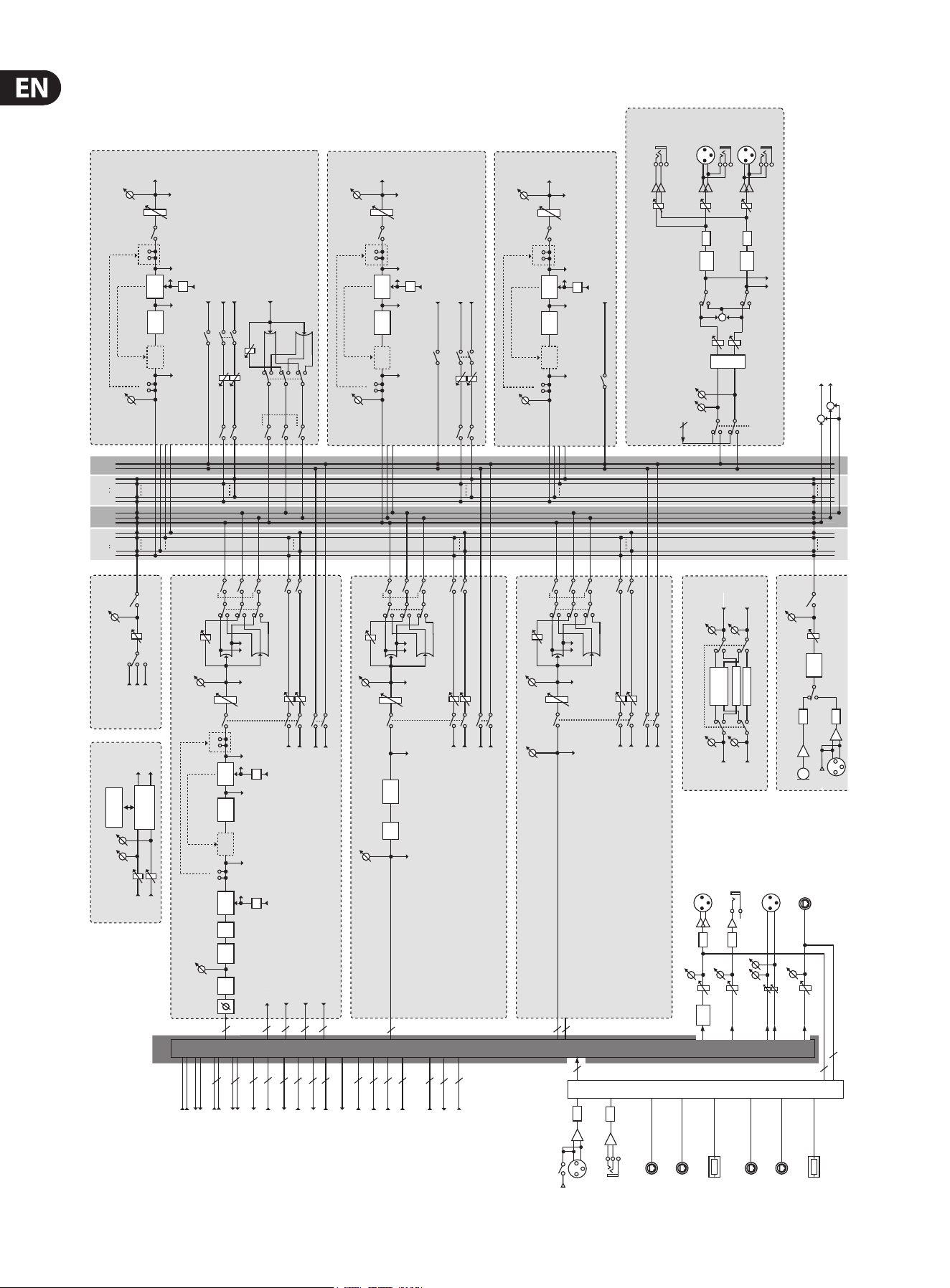
70 X32 DIGITAL MIXER Preliminary User Manual
Block Diagram
MAIN
L R C L R
SOLOMATRIX
1 2 5 6
MIX BUS
1 2 15 16
FADER
MIX 1–16
INSERT
6-BAND
EQ
INSERT
COMP/
EXPAN
KEY-IN
Pre EQ Post EQ
EQ
Pre Fader
Post Fader
Matrix 1,3,5
MUTE
MUTE
SOLO
Post Fader
Post Fader
Post Fader
Post Fader
Matrix 2,4,6
MIX 1-16
OUT
16
EFFECTS 1-8
EFFECT
31 BAND GEQ
31 BAND GEQ
FX OUT L
FX OUT R
FX IN L
FX IN R
USB
PLAY
USB
REC
USB RECORDER
REC
LEVEL
USB
MEMORY
USB MEMORY
RECORDER
L+C/R+C MIX
L+C OUT
R+C OUT
+
+
DSP
PATCH
USB
PLAY
USB
REC
FX 1-8 OUT (L / R)
FX 1-8 IN (L / R)
6
16
8 x 2
8 x 2
MIX 1-16 INSERT RETURN
16
MIX 1-16 INSERT SEND
16
MIX 1-16 OUT
MAIN LRC INSERT RETURN
MATRIX 1-6 INSERT RETURN
6
MATRIX 1-6 INSERT SEND
6
MATRIX 1-6 OUT
3
3
MAIN LRC INSERT SEND
3
MAIN LRC OUT
3
MAIN LRC PRE EQ OUT
PATCH CUE
MONITOR LR OUT
2
MONITOR L+C/R+C OUT
2
2
MONITOR SOURCE IN
I/O
PATCH
A/D
INPUT
(1-32)
AES-50 A
(48ch IN)
AES-50 B
(48ch IN)
SLOT
(32ch IN)
AES-50 A
(48ch OUT)
AES-50 B
(48ch OUT)
SLOT
(32ch OUT)
40
16
AUX
RETURN
(1-6)
+48V
PHANTOM
A/D
TALKBACK
COMP
ON
GAIN
+48V
A/D
A/D
P16 BUS
(16ch)
D/A
OUT 1-16
D/A
AUX OUT 1-6
DELAY
GAIN
GAIN
GAIN
AES/EBU OUT
GAIN
8
AUX Returns 1–8
AUX Returns 7–8 by default on USB Play
Pre EQ
Pre EQ/Pre Fader/Post Fader/Post Pan L
Pre EQ/Pre Fader/Post Fader/Post Pan R
Pre Fader
Mix 1,3...15
Mix 2,4...16
SOLO
4BAND
EQ
ATT
Pre EQ/Pre Fader/Post Fader/Post Pan L
Pre EQ/Pre Fader/Post Fader/Post Pan R
MUTE
MUTE
FADER
LCR
PAN (LR)
PAN (LCR)
GAIN
Post Fader
Post Pan
GAIN
32
32
32
32
32
ATT
CH 1–32
LOW
CUT
GATE/
DUCK
INSERT
4-BAND
EQ
INSERT
COMP/
EXPAN
DELAY
KEY-IN
Pre EQ
Post EQ
EQ
Pre Fader
Mix 1,3...15
Mix 2,4...16
Pre HP/Pre Gate/Post Gate/Pre EQ/Post EQ/Pre Fader/Post Fader/Post Pan L
Pre HP/Pre Gate/Post Gate/Pre EQ/Post EQ/Pre Fader/Post Fader/Post Pan R
KEY-IN
EQ
Pre HP/Pre Gate/Post Gate/Pre EQ/Post EQ/Pre Fader/Post Fader/Post Pan L
Pre HP/Pre Gate/Post Gate/Pre EQ/Post EQ/Pre Fader/Post Fader/Post Pan R
SOLO
INSERT RETURN
INSERT SEND
PRE LOW CUT OUT
POST FADER OUT
MUTE
MUTE
FADER
LCR
PAN (LR)
PAN (LCR)
GAIN
Post Fader
Post Pan
GAIN
COMP/
EXPAN
8 x 2
STEREO FX RETURNS 1 L/R – 8 L/R
Pre Fader/Post Fader/Post Pan L
Pre Fader/Post Fader/Post Pan R
Pre Fader
Mix 1,3...15
Mix 2,4...16
SOLO
Pre Fader/Post Fader/Post Pan L
Pre Fader/Post Fader/Post Pan R
MUTE
MUTE
FADER
LCR
PAN (LR)
PAN (LCR)
GAIN
Post Fader
Post Pan
GAIN
WHITE NOISE
PINK NOISE
OSCILLATOR
SINE WAVE
GENERATE
GAIN
COMP/
EXPAN
LCR
PAN (LR)
PAN (LCR)
GAIN
GAIN
GAIN
+
MONO
MONITOR LR OUT
DELAY
DELAY
MONITOR
D/A
PHONES
OUT
MONITOR L
OUT
D/A
MONITOR R
OUT
SOLO / SOURCE
MONITOR SOURCE IN
DIM
2
GAIN
GAIN
GAIN
FADER
MATRIX
1-6
INSERT
INSERT
KEY-IN
Pre EQ Post EQ
EQ
Pre Fader
Post Fader
MUTE
SOLO
MATRIX 1-6
OUT
Post Fader
COMP/
EXPAN
EQ
6BAND
COMP/
EXPAN
FADER
MAIN LRC
INSERT
6BAND
EQ
INSERT
COMP/
EXPAN
KEY-IN
Pre EQ Post EQ
EQ
GAIN
Pre Fader
Post Fader
Matrix 1,3,5
MUTE
MUTE
SOLO
Post Fader
Post Fader
Post Fader
Matrix 2,4,6
MAIN LRC
OUT
COMP/
EXPAN
mute
mute
mute
mute
mute
mute
mute
mute
mute
stereo
mono
stereo
mute
stereo
mono
stereo
stereo
mono
stereo
stereo
mono
stereo

71 X32 DIGITAL MIXER Preliminary User Manual
X32 MIDI Implementation
MIDI RX > SCENES
Whenever program change messages in the range 1-100 are received on MIDI
CH01, the corresponding scene of the X32 internal show memory will be loaded.
This requires the following preconditions:
• Setup / remote
> MIDI In/Out check marks must be set according to the connection on
which MIDI input will be accepted (via physical MIDI connectors on X32 or
S16, or via XUF Card)
> MIDI In/Out check mark must be set for “Enable MIDI Scene Recall”
• Setup / global
> when tick mark “Conrm Pop-Ups” / “Scene Load” is active, also MIDI
scene recalls will only become active after manual conrmation
> if you prefer activating scenes via MIDI program changes immediately,
un-check the “Conrm Pop-Ups” / “Scene Load” tick mark
• Scenes View / home
> valid scenes must be stored in the internal X32 show le. It is not possible
to recall empty scenes.
> the scope of changes applied by a MIDI scene recall depends on the Scene
Safes, Parameter Safes and Channel Safes settings, same as with recalling
the scene locally.
MIDI TX > SCENES
Every scene can be assigned one specic MIDI command/event. Each time the
scene is loaded the MIDI command will be sent out once. Possible choices for MIDI
commands/events to be found on Scenes View/MIDI page:
• O > no message will be sent upon scene load
• Program Change > select the MIDI Channel and the Program Number
(using knobs 4/5 at the main display)
• Control Change > select the MIDI Channel, Controller number and value
(using knobs 4-6 at the main display)
• Note > select the MIDI Channel, Note number and velocity (using knobs 4-6
at the main display) > will send out a Note On command directly followed by
the same Note O command
MIDI RX > ASSIGN
Whenever assignable controls are set up for transmitting MIDI commands,
reception of that same command (status or continuous) will be reected on the
respective assignable control element (button light, encoder LED collar).
MIDI TX > ASSIGN
We restricted the user assignable MIDI commands to some generic elements,
in order to keep things simple enough:
• Encoders 1-4 > can be assigned to sending control changes, program
changes or notes
> parameters are currently ‘Channel’ and ‘Value’
> for CC and Note commands ‘Value’ = controller number/note number,
and the encoder rotation determines the controller value/note-on velocity
> for Program Changes only the channel is specied, and the encoder
rotation determines the program number
• Buttons 5-12 > can be operated in two modes, ‘MIDI Push’ (non-latching)
for momentary commands, or ‘MIDI Toggle’ (latching) for static commands
MIDI Push:
> can be assigned to sending control changes, program changes or notes
> parameters are currently ‘Channel’ and ‘Value’
> for CC and Note commands ‘Value’ 0…127 = controller number/note
number, and the button momentarily toggles the controller value/note-on
velocity to 127 (depressed)à0 (released]
> for Program Changes ‘Value’ 0…127 = program/preset number, that will
be sent upon pressing the button
MIDI Toggle:
> can be assigned to sending control changes or notes
> parameters are currently ‘Channel’ and ‘Value’
> for CC and Note commands ‘Value’ 0…127 = controller number/note
number, and the button toggles the controller value/note-on velocity
between value/velocity 127 and 0 with every operation
• n.b.1) The ASSIGN section also reects/displays reception of the same MIDI
commands that are selected for transmission
• n.b.2) The MIDI commands assigned to the ASSIGN controls can be
transferred to and from stage via AES50 using the S16 stage box MIDI I/O

72 X32 DIGITAL MIXER Preliminary User Manual
MIDI RX/TX > REMOTE
Enables a specic form of bi-directional MIDI communication for remote
controlling a computer DAW application using control elements of the X32
console. REMOTE can be used in 3 modes, Mackie Control, HUI and raw MIDI CC
(raw) controllers (see Setup/remote)
• MIDI CC (raw) selected and Remote is enabled+active, the group
section buttons
> will emit the following messages on Channel 01:
Group 1-8 SELECT = Note 64-71, on(127)/o(0), push non-latching
Group 1-8 SOLO = CC 32-39, on(127)/o(0), toggle latching
Group 1-8 MUTE = CC 40-47, on(127)/o(0), toggle latching
Sends On Fader = CC 48, on(127)/o(0), toggle latching
Group DCA 1-8 = Note 72, on(127)/o(0), push non-latching
BUS 1-8 = Note 73, on(127)/o(0), push non-latching
BUS 9-16 = Note 74, on(127)/o(0), push non-latching
MTX 1-6 = Note 75, on(127)/o(0), push non-latching
MIDI CC (raw) selected and Remote is enabled+active, then group section
faders 1-8
> will emit CC #0-7, value 0…127 messages on Channel 01
• HUI selected and Remote is enabled+active, then the group fader section
and buttons will emulate the HUI control surface protocol, i.e. for ProTools.
> SELECT/SOLO 1-8 buttons will select or solo the corresponding track in the
DAW, in banks of 8 tracks
> Sends On Fader = enables touch-writing a fader automation on selected
track, track automation mode in DAW must be ‘touch’, (latching)
> use the layer buttons to determine the function assigned to the MUTE 1-8
buttons, the LED displays indicate that function
- Group DCA 1-8 = allows to move the bank selection of tracks in a DAW,
(push non-latching)
- BUS 1-8 = allows to set DAW tracks to ‘Record Ready’, (push non-latching)
- BUS 9-16 = enables using the MUTE buttons for track mute in the DAW,
(latching)
- MTX 1-6 = enables using the MUTE buttons for transport controls in the
DAW, (latching)
• MACKIE CTRL selected and Remote is enabled+active, then the group fader
section and buttons will emulate the Mackie Control Universal protocol
> SELECT/SOLO 1-8 buttons will select or solo the corresponding track in the
DAW, in banks of 8 tracks
> Sends On Fader = enables touch-writing a fader automation on selected
track, track automation mode in DAW must be ‘touch’ or ‘latch’, (latching)
> use the layer buttons to determine the function assigned to the MUTE 1-8
buttons, the LED displays indicate that function
- Group DCA 1-8 = allows to move the bank selection of tracks in a DAW,
(push non-latching)
- BUS 1-8 = allows to set DAW tracks to ‘Record Ready’, (push non-latching)
- BUS 9-16 = enables using the MUTE buttons for track mute in the
DAW, (latching)
- MTX 1-6 = enables using the MUTE buttons for transport controls in the
DAW, (latching)
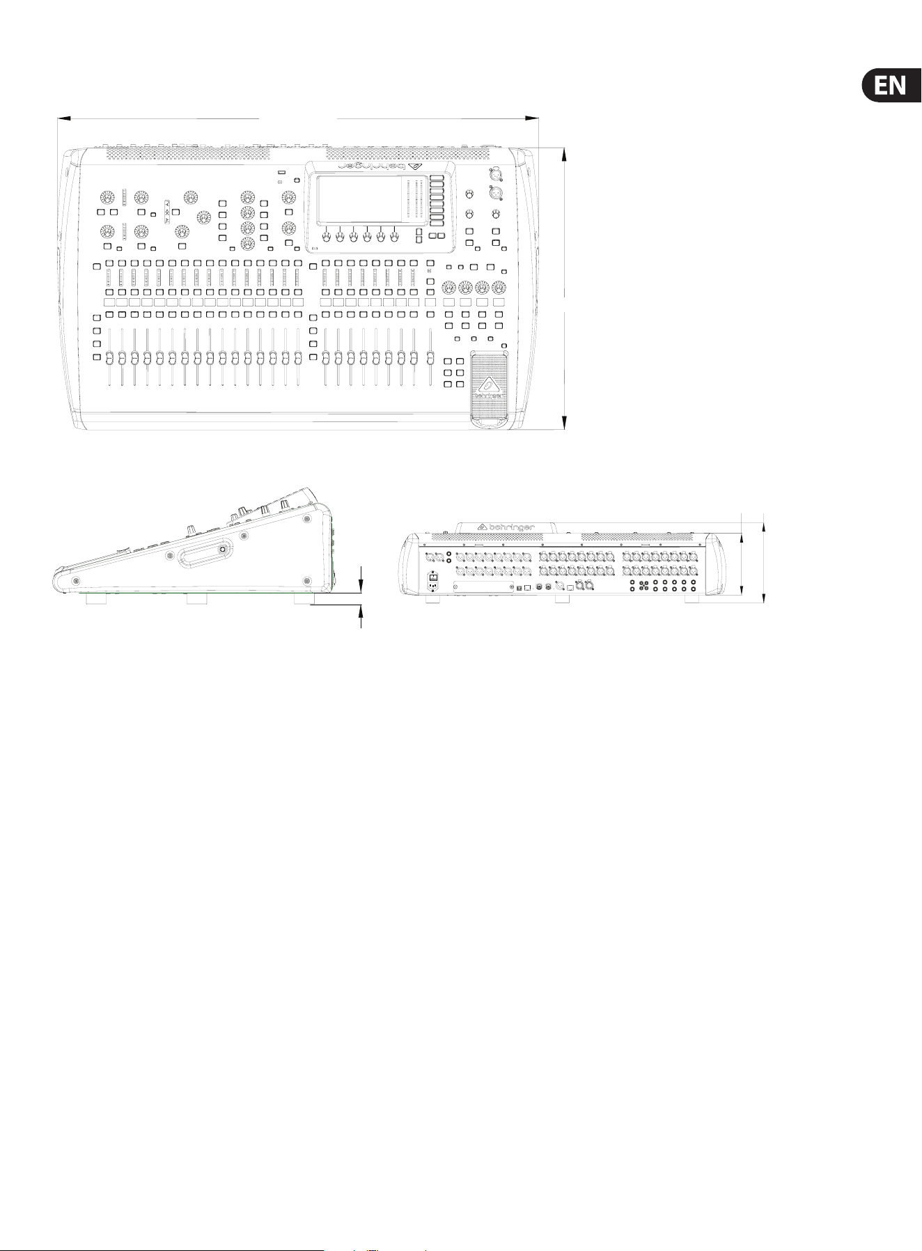
73 X32 DIGITAL MIXER Preliminary User Manual
Dimensions
22.00 mm
169.46 mm
221.33 mm
527.05 mm
900.23 mm
Top view
22.00 mm
169.46 mm
221.33 mm
527.05 mm
900.23 mm
Side view Back view

74 X32 DIGITAL MIXER Preliminary User Manual
FEDERAL COMMUNICATIONS
COMMISSION COMPLIANCE
INFORMATION
Responsible Party Name: MUSIC Group Services NV Inc.
Address: 5270 Procyon Street
Las Vegas, NV 89118
USA
Phone Number: +1 702 800 8290
X32 DIGITAL MIXER
complies with the FCC rules as mentioned in the followingparagraph:
This equipment has been tested and found to comply with the limits for a ClassB
digital device, pursuant to part 15 of the FCC Rules. These limits are designed
to provide reasonable protection against harmful interference in a residential
installation. This equipment generates, uses and can radiate radio frequency
energy and, if not installed and used in accordance with the instructions, may cause
harmful interference to radio communications. However, there is no guarantee that
interference will not occur in a particular installation. If this equipment does cause
harmful interference to radio or television reception, which can be determined
by turning the equipment o and on, the user is encouraged to try to correct the
interference by one or more of the followingmeasures:
• Reorient or relocate the receiving antenna.
• Increase the separation between the equipment and receiver.
• Connect the equipment into an outlet on a circuit dierent from that to which the
receiver is connected.
• Consult the dealer or an experienced radio/TV technician forhelp.
This device complies with Part 15 of the FCC rules. Operation is subject to the
following two conditions:
(1) this device may not cause harmful interference, and
(2) this device must accept any interference received, including interference that may
cause undesired operation.
Important information:
Changes or modications to the equipment not expressly approved by MUSIC Group
can void the user’s authority to use the equipment.
X32 DIGITAL MIXER

Dedicate Your Life to Music