
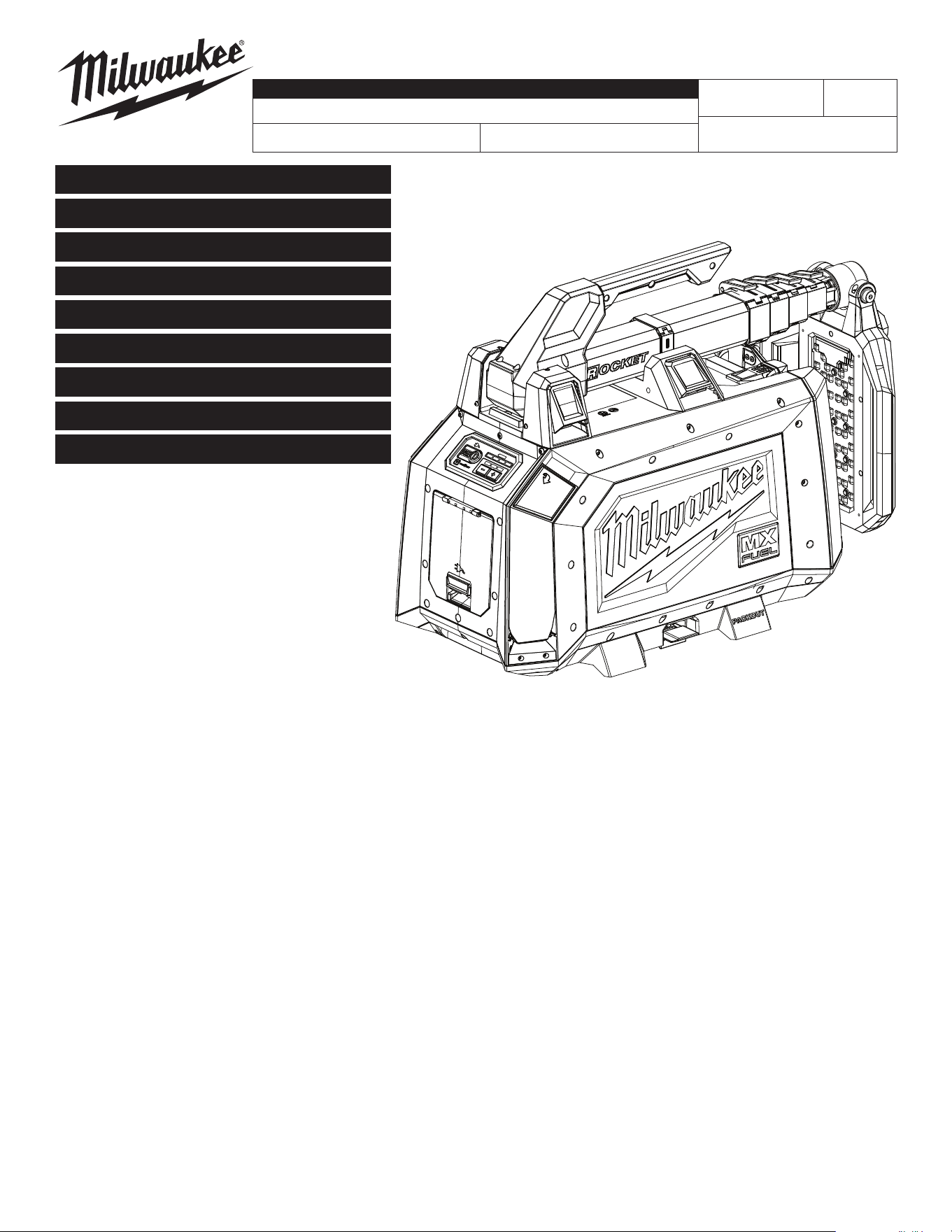
MILWAUKEE TOOL
l
www.milwaukeetool.com
13135 W. Lisbon Road, Brookeld, WI 53005
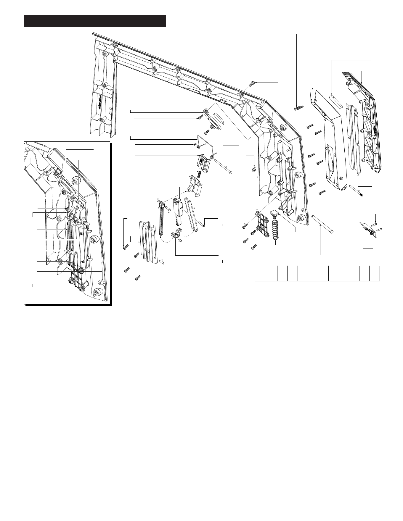
Drwg. 1
SUB ASSEMBLY LISTING PAGE 2
BULLETIN NO.
54-04-1105
SERVICE PARTS LIST
CATALOG NO. MXF040
REVISED BULLETIN
SPECIFY CATALOG NO. AND SERIAL NO. WHEN ORDERING PARTS
MX FUEL™ ROCKET™ DUAL POWER COMPACT TOWER LIGHT
SERIAL NO.
DATE
Aug. 2024
WIRING INSTRUCTION
P20A
See Pages 10-11
Only maintenance, service, repairs, and replacements of parts as dened in the Operator's Manual
can be performed by the user.
All other repairs are to ONLY be performed by personnel authorized by MILWAUKEE TOOL. Do not
attempt to install other parts; this COULD void your tool warranty.
For service, parts, or inquiries, contact us:
• Customer Service at 1.800.SAWDUST (1.800.729.3878)
• E-Service tool repair at: www.milwaukeetool.com/e-service
• Find a local authorized MILWAUKEE service location at Milwaukeetool.com
• Find a MILWAUKEE factory Service Center Location or MILWAUKEE factory Central Repair
Center at Milwaukeetool.com. Send the following, posted paid and insured:
• Your name, address, and phone number
• Description of the issues
• Copy of the proof of purchase
• Tool, charger, and batteries involved with the issues
MILWAUKEE factory Central Repair Centers:
MILWAUKEE TOOL MILWAUKEE TOOL
Central Repair Central Repair
1401 Sycamore Avenue 2198 Southtech Drive
Greenwood, MS 38930 Greenwood, IN 46143
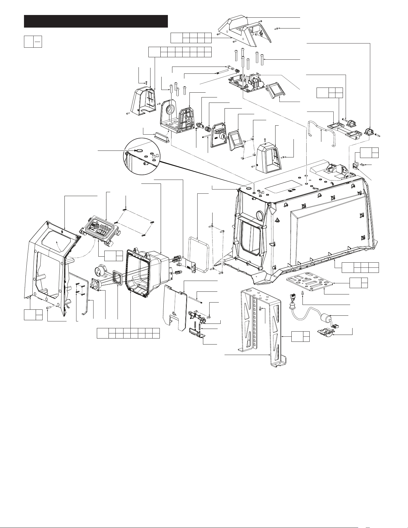
MAIN BODY, UI ASSEMBLIES PAGE 3
BATTERY HOUSING ASSY. PAGE 4
LEFT OUTRIGGER ASSY. PAGE 5
RIGHT OUTRIGGER ASSY. PAGE 6
LIGHT MAST ASSEMBLY PAGE 7
LIGHT MAST ASSEMBLY BOM PAGE 8
TORQUE SPECS CHART PAGE 9
WIRING PAGE 10-11

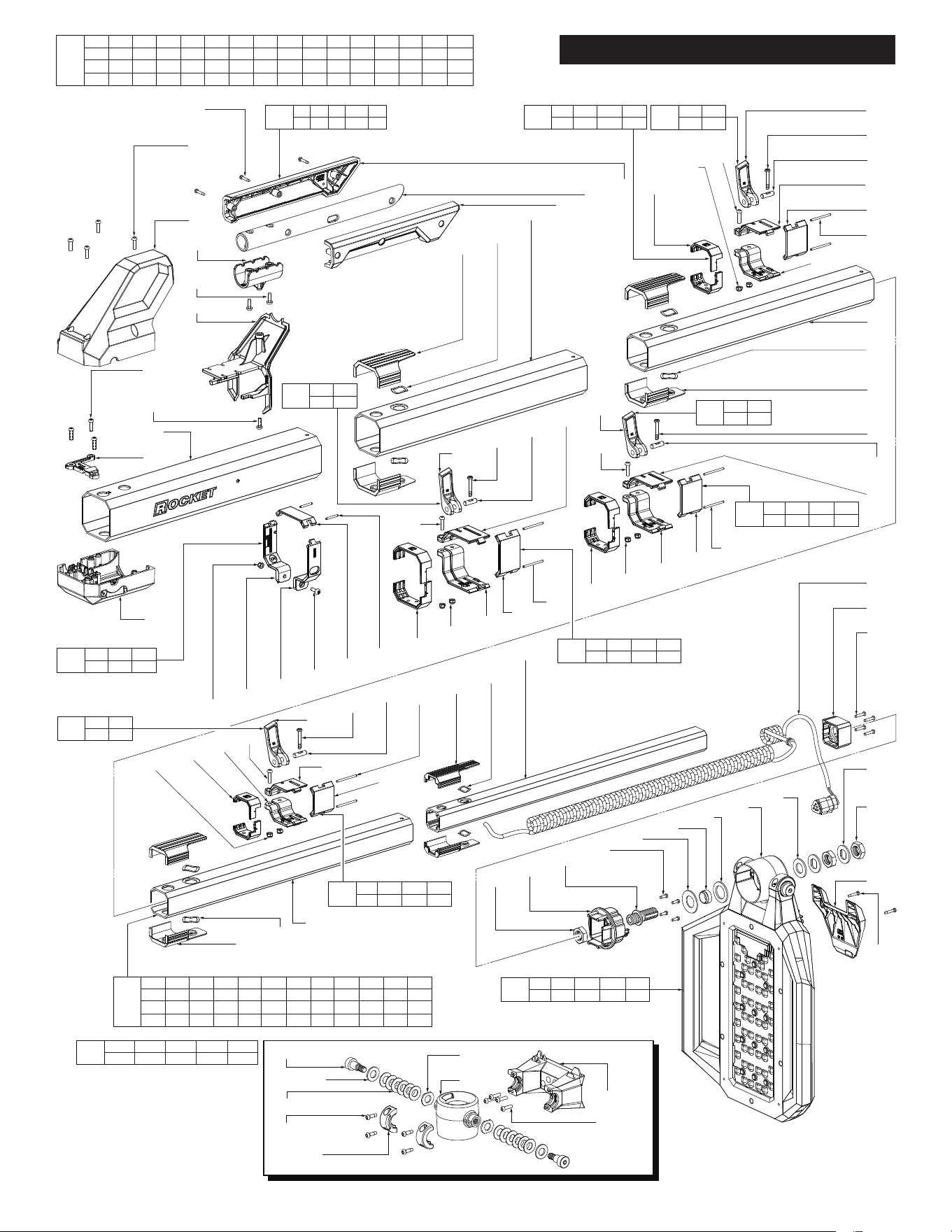
FIG. PART NO. DESCRIPTION OF PART NO. REQ.
1 --------------- Main Housing Gasket (1)
2 --------------- Bottom Housing (1)
3 05-81-9045 M4 x 12mm Pan Hd. Plastite T-15 Screw (48)
0
00
EXAMPLE:
Component Parts (Small #) Are Included
When Ordering The Assembly (Large #).
SUB ASSEMBLY LISTING PAGE 2
FIG. PART NO. DESCRIPTION OF PART NO. REQ.
4 06-82-4003 M4 x 16mm Pan Hd. ST T-20 Screw (6)
5 45-88-0204 Flat Washer (4)
6a 05-74-0242 M6 x 25mm Pan Hd. T-30 Machine Screw (4)
6b 05-74-0242 M6 x 25mm Pan Hd. T-30 Machine Screw (4)
7 --------------- Packout™ Bottom Housing (1)
8 --------------- Packout™ Latch (1)
9 05-88-1220 M4 x 10mm Pan Hd. ST T-20 Screw (40)
10 06-82-6351 M3 x 16mm Pan Hd. ST T-10 Screw (4)
11 --------------- Left Outrigger End Cap (1)
12 31-55-0565 Left Side Badge (1)
13 --------------- Internal Frame Mount Plate (1)
14 31-55-0575 Right Side Badge (1)
15 --------------- Right Outrigger End Cap (1)
16 05-88-1525 M4 x 30mm Pan Hd. ST T-20 Screw (2)
59 05-88-5375 M4 x 13.5mm Pan Hd. Plastite T-15 Screw (14)
93 05-81-1337 M4 x 14mm Pan Hd. T-20 Machine Screw (4)
189 06-82-0217 M4 x 10mm Pan Head Phillips Screw (3)
197 12-20-9985 Service Nameplate (1)
201 --------------- Battery Housing Assembly (See page 4) (1)
202 --------------- UI Assembly (See page 3) (1)
203 44-20-8495 Battery Latch Assembly (See page 3) (1)
204 --------------- Light Mast Assembly (See page 7) (1)
207 14-34-7165 Bottom Housing Assembly (1)
208 42-36-8585 Packout™ Plate Assembly (1)
211 42-36-8590 Lower Washer Kit (1)
233 14-46-9560 Left Outrigger Assembly (See page 5) (1)
234 14-46-9563 Right Outrigger Assembly (See page 6) (1)
239 --------------- Main Body Housing Service Assembly (1)
93
(4x)
#204
Light Mast
Assembly
(See page 7)
#233
Left Outrigger
Assembly
(See page 5)
#203
Battery Latch
Assembly
See page 3)
#239
Main Body
Housing Assy.
(See page 3)
#201
Battery Housing
Assembly
(See page 4)
#234
Right Outrigger Assy.
(See page 6)
#202
UI Assembly
(See page 3)
9
(12x)
16
(2x)
59
(4x)
9
(14x)
9
(14x)
10
(2x)
11
59
(10x)
6b
(4x)
1
2
4
(6x)
3
(26x)
5
(4x)
6a
(4x)
7
3
(22x)
12
14
8
10
(2x)
15
197
189
(3x)
13
207
1 2
3 4
211
6b
13
208
3 7
8
0
00
EXAMPLE:
Component Parts (Small #) Are Included
When Ordering The Assembly (Large #).
75
76
77
(4x)
81
82
39
83
59
(4x)
84
85
9
(2x)
86
87
(2x)
88
40
9
25
(3x)
36
35
(4x)
33
34
30
29
27
19
21
20
6
(4x)
25
(3x)
26
31
32
28
17
18
(4x)
92
(2x)
22
(6x)
91
(2x)
23
24
90
89
38
(2x)
37
41
9
188
42
77
(4x)
78 79 8059
(10x)
203
89 90
91 92
17 18 19 20
21 22 23 24
212
6 25 26 27 28 29 30
31 32 33 34 35 36
213
215
9
41
214
9
40
216
3
75
217
76
77
218
37
38
9 59 77 78 79 80 81
82 83 84 84 86 87 88
219
9 39 40
41 42 188
239
Apply 0.3 grams
Silicon Grease
here
FIG. PART NO. DESCRIPTION OF PART NO. REQ.
6 05-74-0242 M6 x 25mm Pan Hd. T-20 Machine Screw (4)
9 05-88-1220 M4 x 10mm Pan Hd. ST T-20 Screw (4)
17 31-50-6120 Mast Lock Housing (1)
18 05-81-0005 M3 x 11mm Pan Hd. Taptite T-10 Screw (4)
19 --------------- Mast Lock Compression Spring (1)
20 --------------- Mast Lock Pin (1)
21 --------------- Pin (1)
22 06-82-0073 M6 x 36mm Pan Hd. T-30 Machine Screw (6)
23 --------------- Latch Housing (1)
24 --------------- Lever Cam (1)
25 05-74-0900 M3 x 10mm Pan Hd. T-10 Machine Screw (6)
26 23-94-9890 Pivot Wire Outer Shroud (1)
27 --------------- Mast Pivot Base (1)
28 --------------- Pivot Base Wobble Stop (1)
29 --------------- Pivot Locking Piston (1)
30 --------------- Pivot Locking Spring (1)
31 --------------- 10mm Pivot Lock Pin (1)
32 --------------- 36.5mm Pivot Lock Pin (1)
33 --------------- Latch Pivot Base (1)
34 --------------- Mast Pivot Lock (1)
35 --------------- M4 x 7mm Pan Hd. T-20 Machine Screw (4)
36 44-20-8485 Pivot Latch Outer Shroud (1)
37 --------------- Padlock Latch (1)
38 --------------- M3 x 6mm Pan Hd. T-10 Machine Screw (2)
39 43-76-7041 Main Body Housing (1)
40 --------------- Internal Pivot Frame (1)
41 --------------- Top Washer Plate (1)
42 43-76-7042 Main Top Housing Ferrite Cap (1)
59 05-88-5375 M4 x 13.5mm Pan Hd. Plastite T-15 Screw (14)
75 31-12-7001 AC UI Bezel (1)
76 --------------- HMI PCBA (1)
77 05-78-0044 M3 x 12mm Pan Hd. Plast. T-10 TP Screw (8)
FIG. PART NO. DESCRIPTION OF PART NO. REQ.
78 --------------- AC Door Seal (1)
79 --------------- AC Wire Assembly (1)
80 --------------- AC Door Plug Cover (1)
81 --------------- AC Plug Box (1)
82 --------------- Wire Cap (1)
83 --------------- AC Housing Gasket (1)
84 --------------- AC Plug Housing Door (1)
85 --------------- Pin (1)
86 --------------- Fixed Latch (1)
87 --------------- Door Spring (2)
88 --------------- Slide Latch (1)
89 --------------- Metal Latch (1)
90 --------------- Dual Latch (1)
91 --------------- Pin (2)
92 --------------- Black Plate Latch (2)
188 23-94-9841 LED Jumper Wire Assembly (1)
203 44-20-8495 Battery Latch Service Assembly (1)
212 42-78-4015 Mast Lock Service Assembly (1)
213 42-78-4020 Pivot Lock Service Assembly (1)
214 42-36-8595 Internal Frame Service Kit (1)
215 05-90-0560 Top Washer Plate Service Kit (1)
216 31-58-5345 AC Bezel Service Kit (1)
217 31-06-2165 User Interface Service Kit (1)
218 14-46-9565 Padlock Plate Service Kit (1)
219 14-46-9567 AC Box Service Assembly (1)
239 14-38-7201 Main Body Housing Service Assembly (1)
MAIN BODY, UI ASSEMBLIES PAGE 3
FIG. PART NO. DESCRIPTION OF PART NO. REQ.
10 06-82-6351 M3 x 16mm Pan Hd. ST T-10 Screw (4)
43 --------------- Battery Rail - Left (1)
44 --------------- Battery Ejector (1)
45 --------------- Ejection Spring (2)
46 --------------- Ejection Spring Holder (1)
47 --------------- Battery Terminal Block Assembly (1)
48 --------------- Pivot Bushing (2)
49 --------------- M5 x 16mm Pan Hd. ST T-25 Screw (2)
50 --------------- Pivot Latch (1)
51 --------------- Spring (2)
52 --------------- Release Lever (1)
53 --------------- Spring (1)
54 --------------- Spring Holder (1)
55 --------------- Battery Rail - Right (1)
56 05-74-7195 M3 x 11mm Pan Hd. Taptite T-10 Screw (2)
57 42-36-9002 Captive Bracket (1)
58 14-20-0291 OKC PCBA (1)
59 05-88-5375 M4 x 13.5mm Pan Hd. Plastite T-15 Screw (11)
60 --------------- 3V Coin Cell Battery
(See Hardware Store - CR2032)
(1)
61 --------------- M2.6 x 12mm Flat Hd. ST Phillips Screw (2)
62 --------------- One Key Access Door (1)
63 --------------- Firmware Access Door (1)
64 22-80-0651 Programming PCBA (1)
56
(2x)
57
222
59
(3x)
71
58
72
73
74
(8x)
69
70
59
(3x)
66
65
(2x)
64
59
(5x)
67
(2x)
65
(6x)
68
60
61
62
61
63
46
45
(2x)
44
47
50
48
(2x)
52
53
54
43
49
(2x)
51
(2x)
55
10
(4x)
59 65 66 67
68 69 70
231
232
73
74
236
61
62
237
61
63
10 45 46 47 48 49 50
51 52 53 54 55 56 57
238
0
00
EXAMPLE:
Component Parts (Small #) Are Included
When Ordering The Assembly (Large #).
BATTERY HOUSING ASSY. PAGE 4
FIG. PART NO. DESCRIPTION OF PART NO. REQ.
65 --------------- M2.6 x 8mm Pan Hd. ST T-8 Screw (8)
66 --------------- Battery Door Handle (1)
67 --------------- Hinge Pin (2)
68 --------------- Hinge Pin Cover (1)
69 43-44-8565 Power Pack Door Gasket (1)
70 --------------- Battery Door (1)
71 58-10-9966 Battery Box (1)
72 43-44-8522 Power Pack Tub Gasket (1)
73 --------------- Main PCBA (1)
74 05-81-1195 M3 x 8mm Pan Hd. ST T-10 Screw (8)
222 22-09-6630 OKC Coin Cell PCB Service Assembly (1)
231 31-12-9120 Battery Door Service Assembly (1)
232 22-06-0570 Main PCBA Service Assembly (1)
236 31-15-9001 One-Key Cover Kit (1)
237 31-15-9002 Programing Board Cover Service Kit (1)
238 14-20-9502 UL Battery Rail Service Kit (1)
9
(14x)
10
(2x)
11
154 155
162
160 77
(8x)
164
158
159
181
180
165
166
161
169
179
56
(2x)
170
172
167
168
174
172
171
163
156
77
(4x)
177
176
175
157
173
178
77
(4x)
169
166
170
171
172
174
172
173
177
176
175
178
159
180
164
9 10 11 56 77 154 155 156 157 158 159
160 161 162 163 164 165 166 167 168 169 170
171 172 173 174 175 176 177 178 179 180 181
233
FIG. PART NO. DESCRIPTION OF PART NO. REQ.
9 05-88-1220 M4 x 10mm Pan Hd. ST T-20 Screw (14)
10 06-82-6351 M3 x 16mm Pan Hd. ST T-10 Screw (2)
11 --------------- Outrigger Cap - Left (1)
56 05-74-7195 M3 x 11mm Pan Hd. Taptite T-10 Screw (2)
77 05-78-0044 M3 x 12mm Pan Hd. Taptite T-10 Screw (16)
154 --------------- Outrigger Support - Left (1)
155 --------------- Strengthen Leg (1)
156 --------------- 3 x 17.2 OD Lock Pin (1)
157 --------------- Slider (1)
158 --------------- 3 x 42-7 OD Lock Pin (1)
159 --------------- 5 x 67 OD Outrigger Shaft (1)
160 --------------- Outrigger Cover - Left (1)
161 --------------- E-Ring (2)
162 --------------- Metal Block (1)
163 --------------- Outrigger Hinge (1)
164 --------------- Side Bezel - Left (1)
165 --------------- Magnet (1)
166 --------------- Magnet Plate - Left (1)
167 --------------- Release Button (1)
168 --------------- Spring (1)
169 --------------- 3 x 54.4 OD Lock Pin (1)
170 --------------- Coil Spring (1)
171 --------------- Button Lever (1)
172 --------------- C-Ring, E Type (2)
173 --------------- Lock Leg (1)
174 --------------- 3 x 13.5 OD Lock Leg Pin (1)
175 --------------- Level Pin (1)
176 --------------- 3.x 8.2 OD Lock Pin (1)
177 --------------- Lock Lever (1)
178 --------------- Outrigger Track - Left (1)
179 --------------- Spring Stopper (1)
180 --------------- Spring Housing - Left (1)
181 --------------- Spindle Lock Spring (1)
233 14-46-9560 Left Outrigger Assembly (1)
0
00
EXAMPLE:
Component Parts (Small #) Are Included
When Ordering The Assembly (Large #).
LEFT OUTRIGGER ASSY. PAGE 5
9
(14x)
185
168
169
185
56
(2x)
170
172
171
167
168
157
172
173
77
(4x)
186
174
165
161
169
182
187
163
156
77
(4x)
176
177
175
179
181
159
77
(8x)
184
162
183
155
158
170
172
174
173
175
177
176
159
187
10
(2x)
15
9 10 15 56 77 155 156 157 158 159 161
162 163 165 167 168 169 170 171 172 173 174
175 176 177 179 181 182 183 184 185 186 187
234
FIG. PART NO. DESCRIPTION OF PART NO. REQ.
9 05-88-1220 M4 x 10mm Pan Hd. ST T-20 Screw (14)
10 06-82-6351 M3 x 16mm Pan Hd. ST T-10 Screw (2)
15 --------------- Outrigger Cap - Right (1)
56 05-74-7195 M3 x 11mm Pan Hd. Taptite T-10 Screw (2)
77 05-78-0044 M3 x 12mm Pan Hd. Taptite T-10 Screw (16)
155 --------------- Strengthen Leg (1)
156 --------------- 3 x 17.2 OD Lock Pin (1)
157 --------------- Slider (1)
158 --------------- 3 x 42-7 OD Lock Pin (1)
159 --------------- 5 x 67 OD Outrigger Shaft (1)
161 --------------- E-Ring (2)
163 --------------- Outrigger Hinge (1)
165 --------------- Magnet (1)
167 --------------- Release Button (1)
168 --------------- Spring (1)
169 --------------- 3 x 54.4 OD Lock Pin (1)
170 --------------- Coil Spring (1)
171 --------------- Button Lever (1)
172 --------------- C-Ring, E Type (2)
173 --------------- Lock Leg (1)
174 --------------- 3 x 13.5 OD Lock Leg Pin (1)
175 --------------- Level Pin (1)
176 --------------- 3.x 8.2 OD Lock Pin (1)
177 --------------- Lock Lever (1)
179 --------------- Spring Stopper (1)
181 --------------- Spindle Lock Spring (1)
182 --------------- Side Bezel - Right (1)
183 --------------- Outrigger Support - Right (1)
184 --------------- Outrigger Cover - Right (1)
185 --------------- Magnet Plate - Right (1)
186 --------------- Outrigger Track - Right (1)
187 --------------- Spring Housing - Right (1)
234 14-46-9563 Right Outrigger Assembly (1)
RIGHT OUTRIGGER ASSY. PAGE 6
10
(3x)
93
(4x)
94
98
100
(2x)
99
189
(3x)
100
102
101
116
117
(2x)
122
(2x)
123
124
125
(2x)
131
(2x)
117
(2x)
132
133
125
(2x)
127
128
129
135
138
125
(2x)
107
105
(2x)
106
(2x)
128
129
134
113
114
115
(4x)
151
(2x)
146
(2x)
152
10
(2x)
126
137
(2x)
95
96
97
117
(2x)
136
104
120
(2x)
121
100
119
118
117
105
(2x)
103
(2x)
126
127
128
129
130
127
126
108
(2x)
105
(2x)
109
117
(2x)
140
(2x)
141
127
128
129
126
125
(2x)
139
142
110
(2x)
111
(2x)
112
146
145
144
143
(4x)
147
148
149
153
150
10 93 94 95 96
97 98 99 100
220
223
117 127
128 129
223
117 127
128 129
223
117 127
128 129
223
117 127
128 129
117 125 126 139
140 141 142
226
117 125 126 135
136 137 138
227
117 125 126 131
132 133 134
228
229
100 117 118
119 120 121
117 122 123 124
125 126 130
230
10 146 147 148 149
150 151 152 153
225
10 100 102 103 104 105 106 107 108 109 110 111
112 113 114 115 116 117 118 119 120 121 122 123
124 125 126 127 128 129 130 131 132 133 134 135
136 137 138 139 140 141 142 143 144 145 146
224
10 93 94 95 96 97 98 99 100 101 102 103 104 105 106 107
108 109 110 111 112 113 114 115 116 117 118 119 120 121 122 123
124 125 126 127 128 129 130 131 132 133 134 135 136 137 137 139
140 141 142 143 144 145 146 147 148 149 150 151 152 153 189
204
155a 155b 155c 155d 155e
155f 155g 155h 155j
235
155a (2x)
155b (2x)
155c (12x)
155e (4x)
155f (2x)
155d (2x)
155g
155j
155h (4x)
LIGHT MAST ASSEMBLY PAGE 7

FIG. PART NO. DESCRIPTION OF PART NO. REQ.
10 06-82-6351 M3 x 16mm Pan Hd. ST T-10 Screw (5)
93 05-81-1337 M4 x 14mm Pan Hd. T-20 Machine Screw (4)
94 --------------- Handle Receiver Pivot (1)
95 --------------- Handle Halve - Left Side (1)
96 --------------- Pivot Handle (1)
97 --------------- Handle Halve - Right Side (1)
98 --------------- Captive Cap (1)
99 --------------- Handle Cap (1)
100 --------------- M4 x 12mm Pan Hd. T-20 Machine Screw (4)
101 31-12-7002 Pivot Housing Wire Trap Cap (1)
102 --------------- Mast Extrusion 1 (1)
103 --------------- Shim, Extrusion 1 (2)
104 --------------- Mast Extrusion 2 (1)
105 --------------- Wave Washer (6)
106 --------------- Shim, Extrusion 2 (2)
107 --------------- Mast Extrusion 3 (1)
108 --------------- Shim, Extrusion 3 (2)
109 --------------- Mast Extrusion 4 (1)
110 --------------- Shim, Extrusion 4 (2)
111 --------------- Wave Washer (2)
112 --------------- Mast Extrusion 5 (1)
113 --------------- LED Wire Assembly (1)
114 --------------- Mast Cap Spacer (1)
115 --------------- M3 x 15mm Pan Hd. Taptite T-10 Screw (4)
116 --------------- Pivot Housing - Lock Side (1)
117 --------------- M4 Nylock Hex Nut (9)
118 --------------- Mast Lock Collar, 60mm (1)
119 --------------- Mast Lock Collar Side, 60mm (1)
120 --------------- Mast Lock Pin (2)
121 --------------- Mast Lock Collar Back (1)
122 --------------- Square Cam Spacer, 60mm (2)
123 --------------- Square Non Cam Side, 60mm (1)
124 --------------- Square Cam Back (1)
125 --------------- Cam Lock Pin (8)
126 --------------- M4 x 16mm Pan Hd. T-20 Machine Screw (4)
127 --------------- Cam Lever (4)
128 --------------- M4 x 26mm Pan Hd. Phillips Mach. Scr. (4)
129 --------------- Lever Lock Pin (4)
130 --------------- Square Cam Side, 60mm (1)
131 --------------- Square Cam Spacer, 53mm (1)
132 --------------- Square Non Cam Side, 53mm (1)
133 --------------- Square Cam Back, 53mm (1)
FIG. PART NO. DESCRIPTION OF PART NO. REQ.
134 --------------- Square Cam Side, 53mm (1)
135 --------------- Square Cam Side, 45mm (1)
136 --------------- Square Non Cam Side, 45mm (1)
137 --------------- Square Cam Spacer, 45mm (2)
138 --------------- Square Cam Back, 45mm (1)
139 --------------- Square Cam Side, 37mm (1)
140 --------------- Square Cam Spacer, 37mm (2)
141 --------------- Square Non Cam Side, 37mm (1)
142 --------------- Square Cam Back, 37mm (1)
143 --------------- M3 x 9.5mm Pan Hd. Taptite T-10 Screw (4)
144 --------------- Shoulder Stud (1)
145 --------------- Mast Cap (1)
146 --------------- Hex Nut (2)
147 --------------- Conical Spring Washer (1)
148 --------------- Sleeved Bushing (1)
149 --------------- Carriage Washer 3 (1)
150 --------------- Carriage Washer 2 (1)
151 --------------- Carriage Washer 1 (2)
152 --------------- Light Wire Cover (1)
153 --------------- LED PCBA (1)
155a --------------- M Screw TH M8.0 x 1.25-6g (2)
155b --------------- Flat Washer TH 10.5 x 20 x 1.8mm (2)
155c --------------- Conical Spring Washer (12)
155d --------------- Flat Washer w/ DD (2)
155e --------------- M4.0 x 1.411 Pan Hd. T-20 Machine Screw (4)
155f --------------- Carriage Cap (2)
155g --------------- Rotation Cap (1)
155h --------------- M4 x 14mm Pan Hd. T-20 Machine Screw (4)
155j --------------- Pivot Mount (1)
189 06-82-0217 M4 x 10mm Pan Hd. Phillips Screw (3)
204 --------------- Light Mast Assembly (1)
220 14-34-7175 Handle Service Assembly (1)
223 14-46-9649 Cam Lever Service Kit (1)
224 43-40-3035 Mast Service Assembly (1)
225 22-09-6620 Light Head Service Kit (1)
226 14-46-9575 Collar 1 Service Kit (1)
227 14-46-9577 Collar 2 Service Kit (1)
228 14-46-9580 Collar 3 Service Kit (1)
229 14-46-9590 Collar 5 Service Kit (1)
230 14-46-9585 Collar 4 Service Kit (1)
235 14-46-9651 Light Head Hinge Service Kit (1)
LIGHT MAST ASSEMBLY BOM PAGE 8
SCREW TORQUE SPECIFICATIONS
SEAT TORQUE
FIG. PART NO. DESCRIPTION OF FASTENER WHERE USED (lb-in) (kgf-cm)
3 05-81-9045 M4 x 12mm Pan Hd. Plastite T-15 Screw Bottom Housings, UI Assy., Batt. Hsg. 6.0±0.6 7±0.7
4 06-82-4003 M4 x 16mm Pan Hd. ST T-20 Screw Bottom Housing 8.6±0.8 10±1
6a 05-74-0242 M6 x 25mm Pan Hd. T-30 Machine Screw Bottom Housing 17.3±1.7 20±2
6b 05-74-0242 M6 x 25mm Pan Hd. T-30 Machine Screw Internal Frame Mount Plate 30.3±3.0 35±3.5
9 05-88-1220 M4 x 10mm Pan Hd. ST T-20 Screw Battery Box, Right & Left Outriggers 5.2±0.5 6±0.6
10 06-82-6351 M3 x 16mm Pan Hd. ST T-10 Screw Right & Left Outrigger End Caps 3.4±0.4 4±0.5
16 05-88-1525 M4 x 30mm Pan Hd. ST T-20 Screw Battery Box 5.2±0.5 6±0.6
59 05-88-5375 M4 x 13.5 Pan Hd. Plastite T-15 Screw UI Assembly, Battery Housing Assembly 6.0±0.6 7±0.7
93 05-81-1337 M4 x 14mm Pan Hd. T-20 Machine Screw Handle Receiver Pivot
21.6±2.1
25±2.5
189 06-82-0217 M4 x 10mm Pan Head Phillips Screw Pivot Hsg. Wire Trap Cap 15.6±1.5 18±1.8
6 05-74-0242 M6 x 25mm Pan Hd. T-30 Machine Screw Mast Pivot Base 30.3±3.0 35±3.5
9 05-88-1220 M4 x 10mm Pan Hd. ST T-20 Screw
Fixed Latch, Top Washer Plate, Internal Pivot Frame, Batt. Hsg. Assy.
5.2±0.5
6±0.6
18 05-81-0005 M3 x 11mm Pan Hd. Taptite T-10 Screw Mast Lock Housing 3.4±0.4 4±0.5
22 06-82-0073 M6 x 36mm Pan Hd. T-30 Machine Screw Latch Housing 30.3±3.0 35±3.5
25 --------------- M3 x 10mm Pan Hd. T-10 Machine Screw Pivot Wire & Pivot Latch Outer Shrouds 5.2±0.5 6±0.6
35 --------------- M4 x 7mm Pan Hd. T-20 Machine Screw Mast Pivot Lock 13.0±1.3 15±1.5
38 --------------- M3 x 6mm Pan Hd. T-10 Machine Screw Padlock Latch 4.3±0.4 5±0.5
59 05-88-5375 M4 x 13.5 Pan Hd. Plastite T-15 Screw AC UI Bezel, AC Plug Box 6.0±0.6 7±0.7
59 05-88-5375 M4 x 13.5 Pan Hd. Plastite T-15 Screw AC UI Bezel, AC Plug Box 6.0±0.6 7±0.7
77 05-78-0044 M3 x 12mm Pan Hd. Plast. T-10 TP Screw AC Wire Assembly, HMI PCBA 4.3±0.4 5±0.5
10 06-82-6351 M3 x 16mm Pan Hd. ST T-10 Screw Battery Rail - Right 10.4±1.0 12±1.2
49 --------------- M5 x 16mm Pan Hd. ST T-25 Screw Pivot Bushings 21.6±2.1 25±2.5
56 05-74-7195 M3 x 11mm Pan Hd. Taptite T-10 Screw Captive Bracket 3.4±0.4 4±0.5
59 05-88-5375 M4 x 13.5 Pan Hd. Plastite T-15 Screw Battery Door Handle, Battery Box 6.0±0.6 7±0.7
59 05-88-5375 M4 x 13.5 Pan Hd. Plastite T-15 Screw Battery Door Handle, Battery Box 6.0±0.6 7±0.7
61 --------------- M2.6 x 12mm Flat Hd. ST Phillips Screw One Key & Firmware Access Doors 2.1±0.4 2.5±0.5
65 --------------- M2.6 x 8mm Pan Hd. ST T-8 Screw Hinge Pin Cover, Programming PCBA 2.6±0.4 3±0.5
74 05-81-1195 M3 x 8mm Pan Hd. ST T-10 Screw Main PCBA 2.6±0.4 3±0.5
9 05-88-1220 M4 x 10mm Pan Hd. ST T-20 Screw Outrigger Side Bezel - Left 5.2±0.5 6±0.6
10 06-82-6351 M3 x 16mm Pan Hd. ST T-10 Screw Outrigger Cap - Left 2.6±0.4 4±0.5
56 --------------- M3 x 11mm Pan Hd. Taptite T-10 Screw Magnet Plate - Left 2.6±0.4 4±0.5
77 05-78-0044 M3 x 12mm Pan Hd. Plast. T-10 TP Screw Outrigger Cover & Track, Spring Hsg. 2.6±0.4 4±0.5
9 05-88-1220 M4 x 10mm Pan Hd. ST T-20 Screw Outrigger Side Bezel - Right 5.2±0.5 6±0.6
10 06-82-6351 M3 x 16mm Pan Hd. ST T-10 Screw Outrigger Cap - Right 2.6±0.4 4±0.5
56 --------------- M3 x 11mm Pan Hd. Taptite T-10 Screw Magnet Plate - Right 2.6±0.4 4±0.5
77 05-78-0044 M3 x 12mm Pan Hd. Plast. T-10 TP Screw Outrigger Cover & Track, Spring Hsg. 2.6±0.4 4±0.5
10 06-82-6351 M3 x 16mm Pan Hd. ST T-10 Screw Handle Halve - Left 10.4±1.0 12±1.2
10 06-82-6351 M3 x 16mm Pan Hd. ST T-10 Screw Light Wire Cover 6.0±0.6 7±0.7
93 05-81-1337 M4 x 14mm Pan Hd. T-20 Machine Screw
Handle Receiver Pivot, Pivot Hsg. Wire Trap Cap
21.6±2.1
25±2.5
100 --------------- M4 x 12mm Pan Hd. T-20 Machine Screw
Captive Cap, Handle Cap
21.6±2.1
25±2.5
100 --------------- M4 x 12mm Pan Hd. T-20 Machine Screw
Mast Lock Collar Side
13.0±1.3
15±1.5
115 --------------- M3 x 15mm Pan Hd. Taptite T-10 Screw Mast Cap Spacer 13.0±1.3 15±1.5
126 --------------- M4 x 16mm Pan Hd. T-20 Machine Screw Square Cam Side,
(37mm, 45mm, 53mm, 60mm)
6.0±0.6
7±0.7
128 --------------- M4 x 26mm Pan Hd. Phillips Mach. Scr. Lever Lock Pins 3.3±0.4 3.5±0.5
143 --------------- M3 x 9.5mm Pan Hd. Taptite T-10 Screw Mast Cap 13.0±1.3 15±1.5
189 06-82-0217 M4 x 10mm Pan Head Phillips Screw Pivot Hsg. Wire Trap Cap 15.6±1.5 18±1.8
PAGE
2
PAGE
3
PAGE
4
PAGE
5
PAGE
6
PAGE
7/8
WIRING INSTRUCTIONS PAGE 9
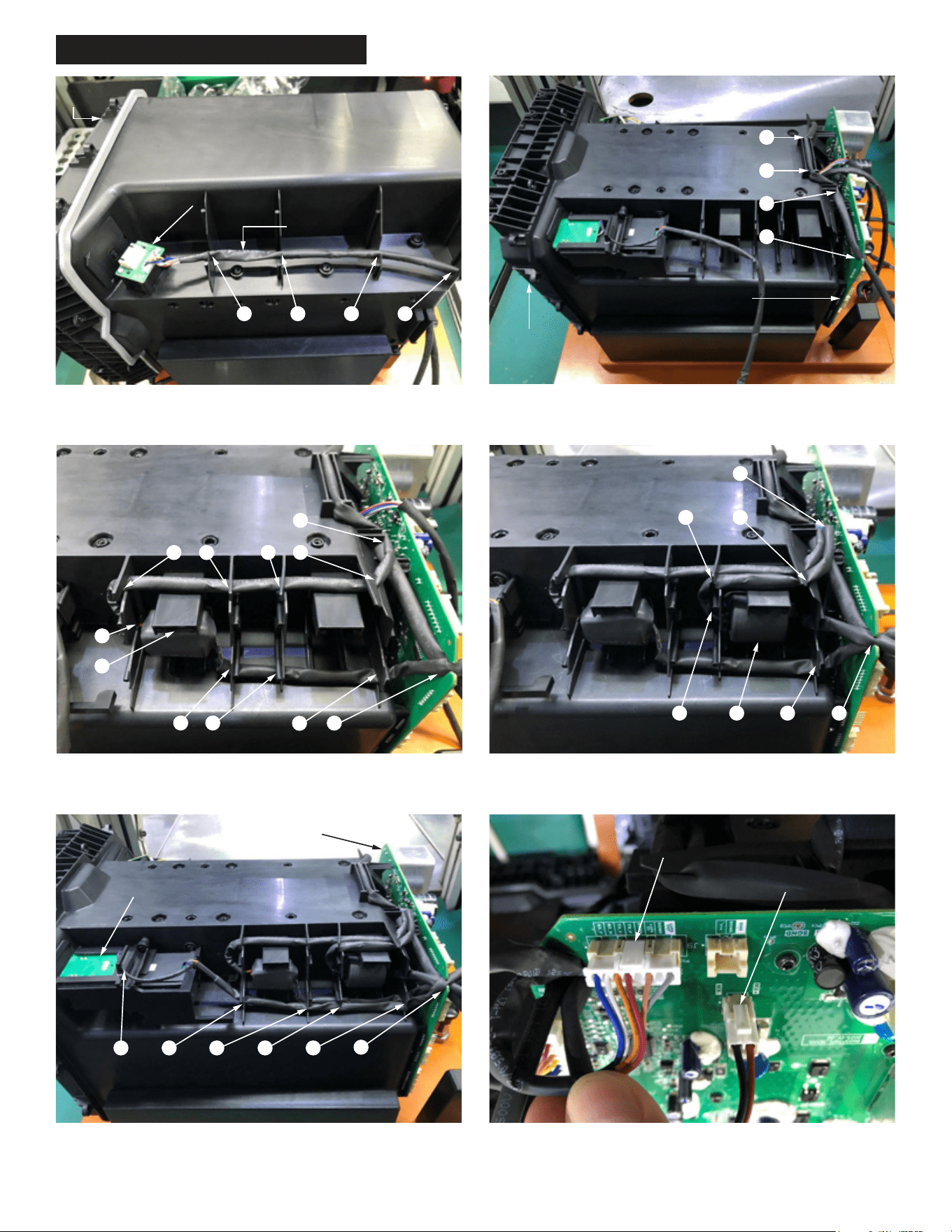
STEP 1: Place the sleeved Programming PCB wires into wire traps 1
through 4 of Battery Box. Be sure to press wires completely down in traps.
4
3
21
Programming PCBA
Battery
Box
Sleeved Wires
4
3
2
1
Main PCBA
Battery
Box
STEP 2: Route the sleeved Programming PCB wires into wire traps 1-3
of Battery Box and trap 4 of Main PCBA. Be sure to press wires
completely down in traps.
STEP 3: Route the sleeved long wire of Battery Terminal Block into wire
traps 1-10 of Battery Box and wire trap 11 of the Main PCBA, as shown.
Be sure all wires are pressed completely down in the traps.
4
3
2
1
10
11
5
6
7
8 9
4
3
2
1
5 6
7
STEP 4: Route the sleeved short wire of Battery Terminal Block into wire
traps 1-6 of Battery Box and wire trap 7 of the Main PCBA, as shown.
Be sure all wires are pressed completely down in the traps.
4
3
21 5
6
STEP 5: Route the sleeved wires of the One Key PCB into wire traps 1-5
of Battery Box and wire trap 6 of the Main PCBA, as shown. Be sure all
wires are pressed completely down in the traps.
One Key PCB
Main PCBA
STEP 6: Install the connectors from the sleeved short and long wires of
Battery Terminal Block to the Main PCBA as shown. Be sure connectors
fit firmly and squarely in place.
Connector of long wire from Battery
Terminal Block
Connector of short wire from
Battery Terminal Block
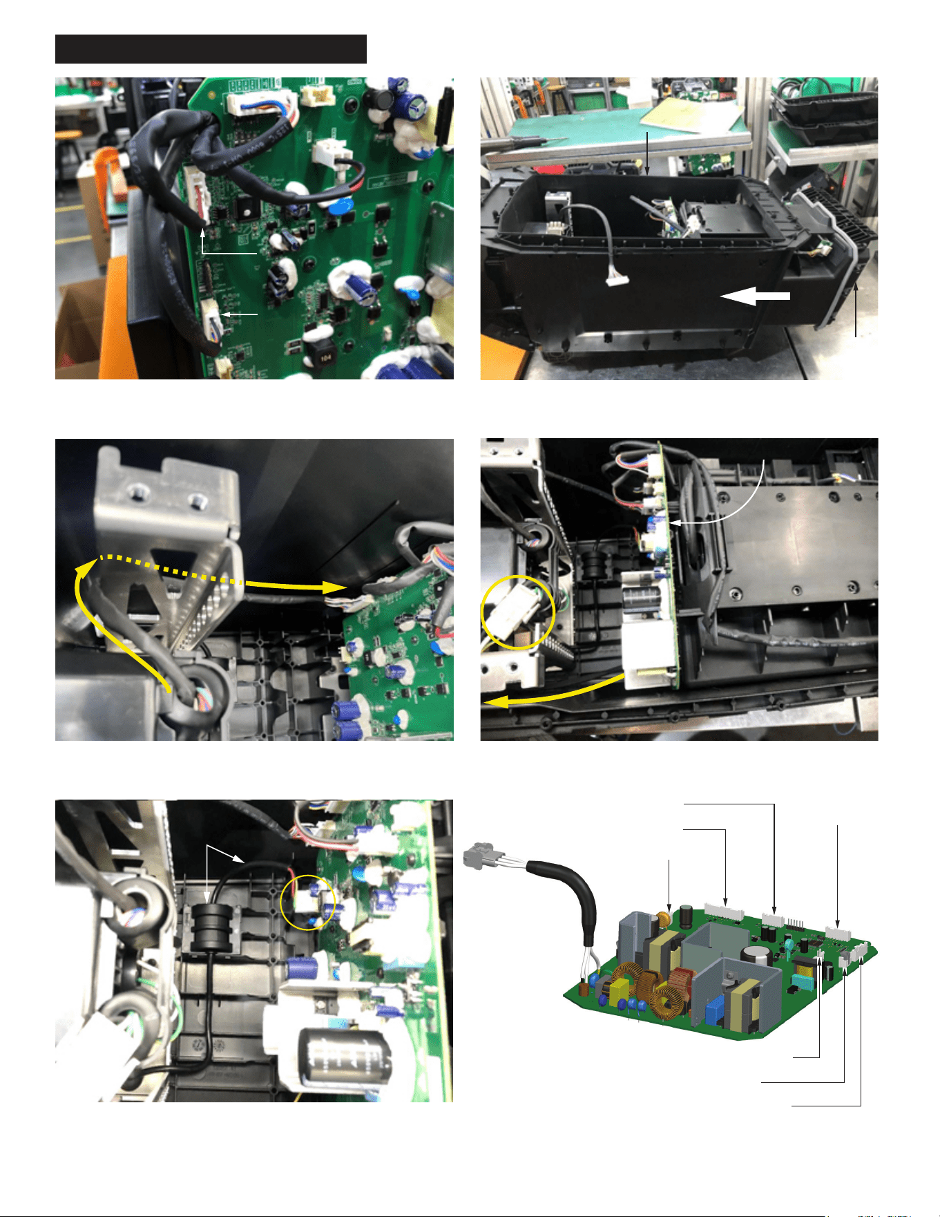
WIRING INSTRUCTIONS PAGE 10
STEP 7: Install the Programming PCB connector and the One Key Card
PCB connector to the Main PCBA. Be sure connectors are seated firmly
and squarely in place.
Programming PCB Connector
One Key Card PCB Connector
Battery
Housing
Assembly
Main Body Housing
STEP 8: Install the Battery Housing Assembly into Main Body Housing.
STEP 9: Route sleeved wires from the User Interface Assembly as shown,
around and over the frame bend. Install the connector to the Main PCBA.
Be sure connector is seated firmly and squarely in place.
STEP 10: Route the AC Wire around and over the frame bend as shown.
Join the AC Wire Connector to the Main PCBA. Be sure connector is
seated firmly and squarely in place.
Main PCBA
LED Jumper
Wire Assembly
STEP 11: Route LED Jumper Wire Assembly through wire traps as shown.
Attach connector from that wire assembly to Main PCBA. Be sure con-
nector and assembly components are seated firmly and squarely in place.
One Key Card Connector here
User Interface Connector here
AC Wire Connector here
Programming
Connector
here
Short Wire Battery Connector here
LED Jumper Connector here
Long Battery Wire Connector here
Main PCBA