
Triton 650Rz / Triton 750Rz / Triton 850Rz
Triton Series
Cybenetics Gold ATX 3.1 & PCIe 5 Fully Modular ATX Power Supply
▓ Supports 12V-2x6 PCIe connector with ATX 3.1 standard
▓ Latest PCIe Gen 5 standard to support up to 2X power excursion
▓ Silent running 120mm HMB cooling fan
▓ Black embossed cable design
▓ Full Japanese electrolytic capacitors
▓ High efficiency with Cybenetics Gold certification
▓ 24/7 continuous power output with 40℃ operating temperature
▓ Compact design with a 140mm depth for easy integration
1. AC INPUT
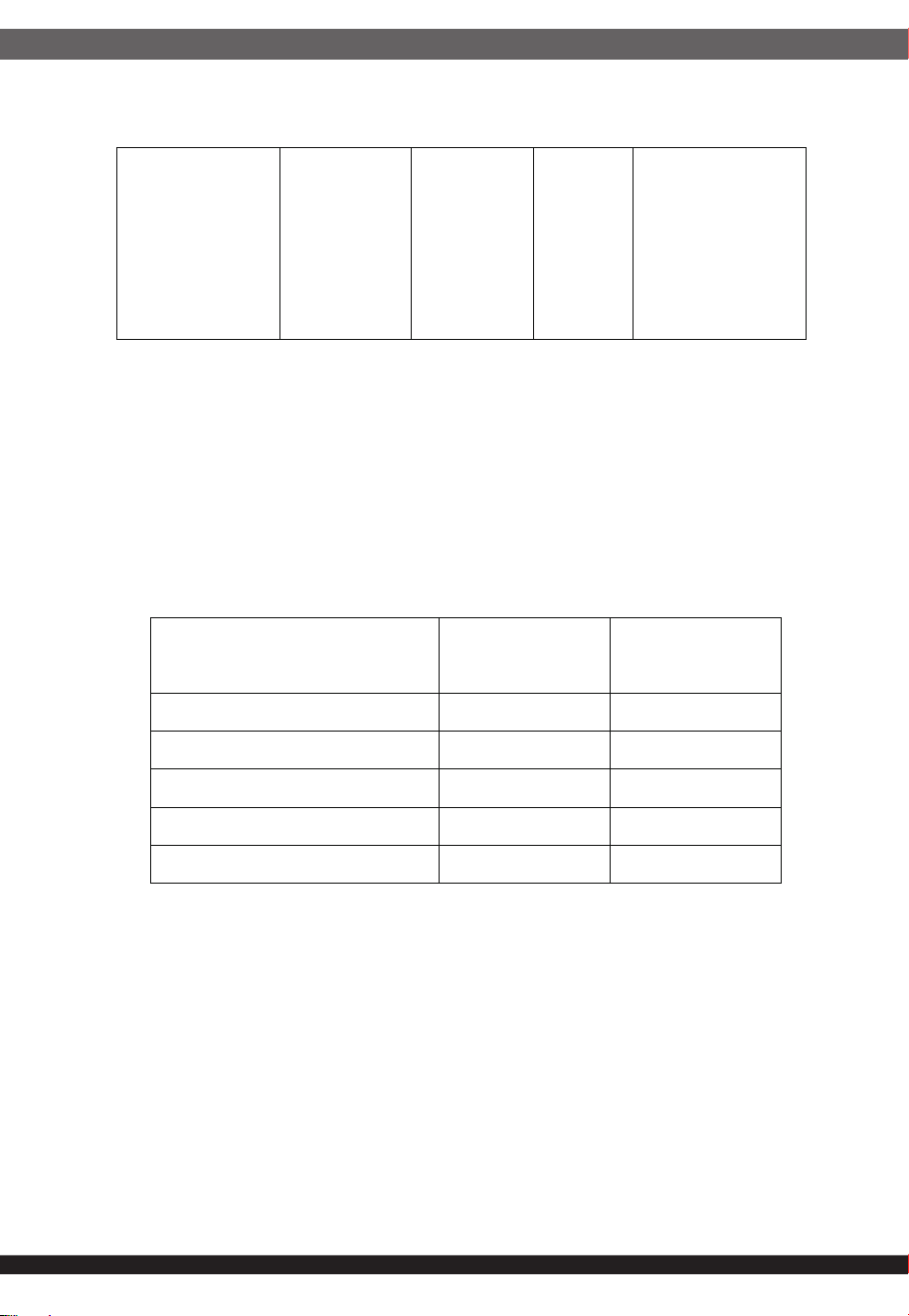
1.1 AC input requirements
The input voltage, current, and frequency requirements for continuous
operation are stated below.
1.2 Inrush current regulation
Power factor correction (PF)>0.90 at full load.
100 A @ 230Vrms (at 25°C ambient cold start).
50A @ 115Vrms
Table1
AC Input Line Requirements
650W / 750W / 850W
Triton 650Rz / Triton 750Rz
Triton 850Rz
Triton
SST-TR650R-GM / SST-TR750R-GM
SST-TR850R-GM
ATX Switching Power Supply
Cybenetics Gold efficiency certified.
This specification describes the requirements of 650W 750W 850 Watts
switching power supply with an stretch form-factor and ATX12V, +5V standby
voltage, remote on/off control, full range line input capability and forced air
cooling characteristics.
Parameter Min. Nom. Max. Unit
Vin 90 100-240 264 VACrms
Frequency 47 50 ------ 60 63 Hz
850W ( Iin )
10 -------- 5 Arms
750W ( Iin )
9 ------ 4.5 Arms
650W ( Iin )
8 ------- 4 Arms
2.2 Load ranges
2.2.1( 850 Watts )
2.2.2 ( 750 Watts )
( 1 ) Maximum continuous total DC output power should not exceed 850W.
( 2 ) Maximum continuous combined load on +3.3 VDC and +5 VDC outputs
shall not exceed 100W.
( 3 ) Maximum combined current for the 12 V outputs shall be 70.8A.
( 1 ) Maximum continuous total DC output power should not exceed 750W.
( 2 ) Maximum continuous combined load on +3.3 VDC and +5 VDC outputs
shall not exceed 100W.
( 3 ) Maximum combined current for the 12 V outputs shall be 62.5A.
Parameter Min Nom. Max Unit
+3.3V 0 - 18 Amps
+5V 0 - 18 Amps
+12V 0 - 62.5 Amps
-12V 0 - 0.3 Amps
+5VSB 0 - 3 Amps
02
2. DC OUTPUT
2.1 DC voltage regulation
Parameter Range Min Nom. Max Unit
+3.3V
±5%
+3.14 +3.3 +3.47 Volts
+5V
±5%
+4.75 +5 +5.25 Volts
+12V
±5%
+11.40 +12 +12.60 Volts
-12V
±10%
-10.80 -12 -13.20 Volts
+5VSB
±5%
+4.75 +5 +5.25 Volts
Parameter Min Nom. Max Unit
+3.3V 0 - 18 Amps
+5V 0 - 18 Amps
+12V 0 - 70.8 Amps
-12V 0 - 0.3 Amps
+5VSB 0 - 3 Amps
03
( 1 ) Maximum continuous total DC output power should not exceed 650W.
( 2 ) Maximum continuous combined load on +3.3 VDC and +5 VDC outputs
shall not exceed 100W.
( 3 ) Maximum combined current for the 12 V outputs shall be 54.1A.
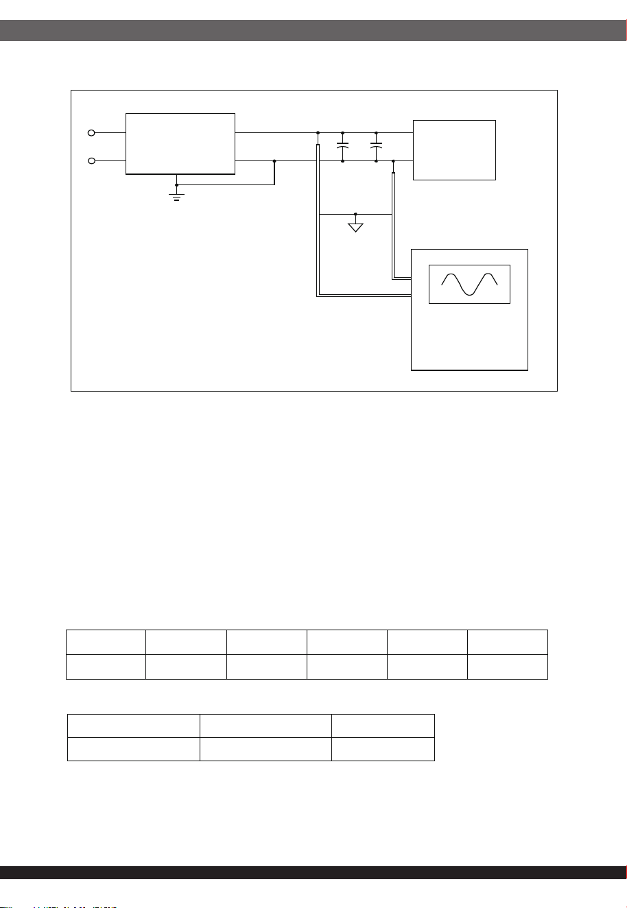
The ripple voltage of the outputs shall be measured at the pins of the
output connector when terminated in the load impedance specified in
figure 1. Ripple and noise are measured at the connectors with a 0.1uF
ceramic capacitor and a 10uF electrolytic capacitor to simulate system
loading. Ripple shall be measured under any condition of line voltage,
output load, line frequency, operation temperature.
2.3 Output Ripple
2.2.3( 650 Watts )
2.3.1 Ripple regulation
2.3.2 Definition
Parameter
Ripple&Noise
( Intel )
Unit
+3.3V 50 mVp-p
+5V 50 mVp-p
+12V 120 mVp-p
-12V 120 mVp-p
+5VSB 50 mVp-p
Parameter Min Nom. Max Unit
+3.3V 0 - 18 Amps
+5V 0 - 18 Amps
+12V 0 - 54.1 Amps
-12V 0 - 0.3 Amps
+5VSB 0 - 3 Amps
04
2.3.3 Ripple voltage test circuit
Figure 1. Ripple voltage test circuit
Any overshoot at turn on or turn off shall be less 10% of the normal
voltage value.
When the logic level "PS-ON" is low, the DC outputs are to be enabled.
When the logic level is high or open collector, the DC outputs are to be
disabled.
2.4 Overshoot
Power supply efficiency typical 87%/20% Loading, 90%/50% Loading,
87%/100% Loading, at normal AC 115V voltage.
2.5 Efficiency
2.5.1 For Gold
2.5.2 Recommended System DC and AC Power Consumption (+5VSB)
2.5.3 Low Load Efficiency Requirements
2.6 Remote ON/OFF control
AC H ot
AC N eutra l
Power Supply
V ou t
V return
10uF 0.1uF
Load
Scope
AC Ground
+5VSB 45mA 90m A 0.55A 1A Max Load
Efficiency 45% 55% 75% 75% 75%
Low Load Efficiency 10W 2%
Required 60% 60%
05
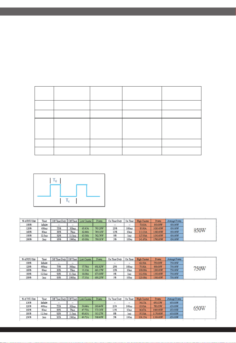
The PSU is subjected to a load change as shown in the table below at a
rate of 1A/μsec (unless otherwise specified).
The frequency of change is set to give the best readability of the deviation and
setting time.
All other output loads and the AC line voltage are chosen in order to obtain the
worst case condition
2.7 Dynamic loading
2.7.1 Duty Cycle Definition
2.7.2 Duty Cycle Example Test Criteria for 850W PSU
Duty Cycle Example Test Criteria for 750W PSU
Duty Cycle Example Test Criteria for 650W PSU
Output
Load
Caps [μF] (option)
Current slew rate Step Load Size ( Intel )
Maximum Step Size
(A)
3.3V 3300 1A/μs 30% of Max Load -
5V 3300 1A/μs 30% of Max Load -
12V 6600 1A or 5A/us
Steps from 100%-
200%
30% -100%
-
-12V 300 0.1A/μs - 0.1
+5VSB 3300 0.1A/μs - 0.5
06
3.1 Over current protection
3.2 Under voltage protection.
3.3 Over voltage protection
3. PROTECTION
The power supply shall have current limit to prevent the +3.3V,+5Vand +12V
outputs from exceeding the values shown in the following Table. If the current
limits are exceeded the power supply shall shutdown and latch off.
In an under voltage fault occurs, the supply will latch all DC outputs into a
shutdown state when +12V,+5V & +3.3V outputs under 60% of it's maximum
value.
output Minimum Nominal Maximum Unit
+12 VDC 13.4 15.0 15.6 Volts
+5 VDC 5.74 6.3 7.0 Volts
+3.3 VDC 3.76 4.2 4.3 Volts
Voltage Over Current Limit (Iout limit)
850W,+12V 85A minimum; 113A maximum
+5V 21A minimum; 27A maximum
+3.3V 21A minimum; 27A maximum
Voltage Over Current Limit (Iout limit)
750W,+12V 75A minimum; 100A maximum
+5V 21A minimum; 27A maximum
+3.3V 21A minimum; 27A maximum
Voltage Over Current Limit (Iout limit)
650W,+12V 65A minimum; 86.5A maximum
+5V 21A minimum; 27A maximum
+3.3V 21A minimum; 27A maximum
07
3.4 Short circuit
4. TIMING
An output short circuit is defined as any output impedance of less than 0.1
ohms. The power supply shall shut down and latch off for shorting the +3.3
VDC,+5 VDC,or+12 VDC rails to return or any other rail. Shorts between main
output rails and +5VSB shall not cause any damage to the power supply. The
power supply shall either shut down and latch off or fold back for shorting the
negative rails.+5VSB must be capable of being shorted indefinitely, but when
the short is removed, the power supply shall recover automatically or by cycling
PS_ON#. The power supply shall be capable of withstanding a continuous
short-circuit to the output without damage or overstress to the unit
3.5 Over-power protection
3.6 Over Temperature Protection (OTP)
The power supply will be shutdown and latch off when output power is
120%~160%.
The power supply shall include an over-temperature protection sensor,
which can trip and shut down the power supply at a preset temperature point.
Such an overheated condition is typically the result of internal current over-
loading or a cooling fan failure. If the protection circuit is non-latching, then it
should have hysteresis built in to avoid intermittent tripping. PSU connectors,
cables and all other components should not be melted or damaged prior
reaching to the OCP trigger. Test condition AC 115/230V.
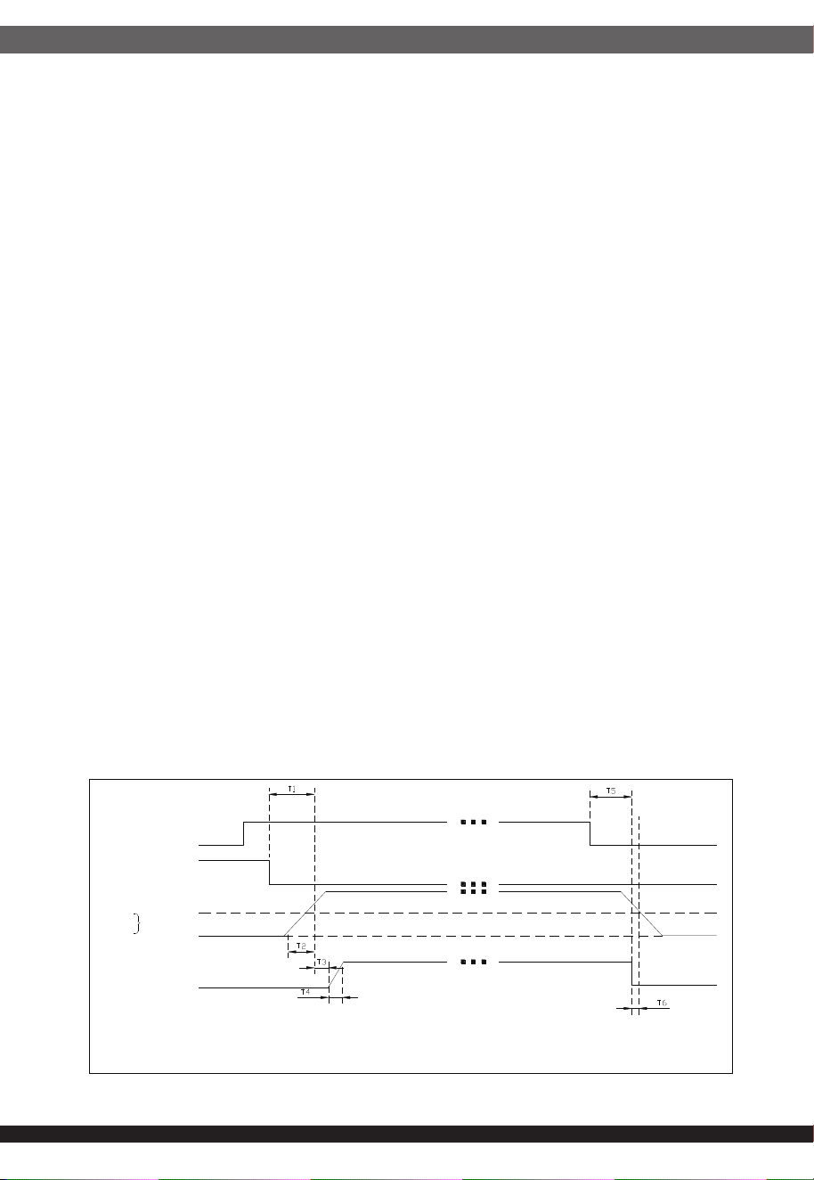
4.1 Signal timing drawing
Figure 2. is a reference for signal timing for main power connector signals and
rails.
Figure 2. PS-OK Timing Sequence
VAC
PS_ON#
Outputs
+12 VDC
+5 VDC
+3.3 VDC
95%
10%
PWR_O
K
PWR_OK Sense level=95% of nominal
T1:Power-on time < 500ms
T2:Rise time 0.2-20ms
T3:PWR_OK delay 100-250ms
T4:PWR_OK rise time < 10ms
T5:AC loss to PWR_OK hold-up time > 11ms
T6:PWR_OK inactive to DC loss delay > 1ms
4.2 Hold up time
When the power loss its input power, it shall maintain 11ms in regulation limit at
normal input voltage. Tested at 100% of maximum load and over 115V/60Hz or
230V/50Hz AC input.
P
Parameter
D
Description
V
Value
L
Legacy Timings
1
1
R
Required
R
Recommended
T0 AC power on time — <2s —
T1 Power-on time
7
<500ms <200ms <150ms
8
T2 Rise time — 0.2-20ms —
T3 PWR_OK delay
7
100ms
2
-500ms 100ms
2
-250ms 100ms
2
-150ms
8
T4 PWR_OK rise time — <10ms —
T5
AC loss to
PWR_OK hold-up
time
— >11ms
3
>16ms
4
T6
PWR_OK inactive
to DC loss delay
— >1ms
5
>1ms
6
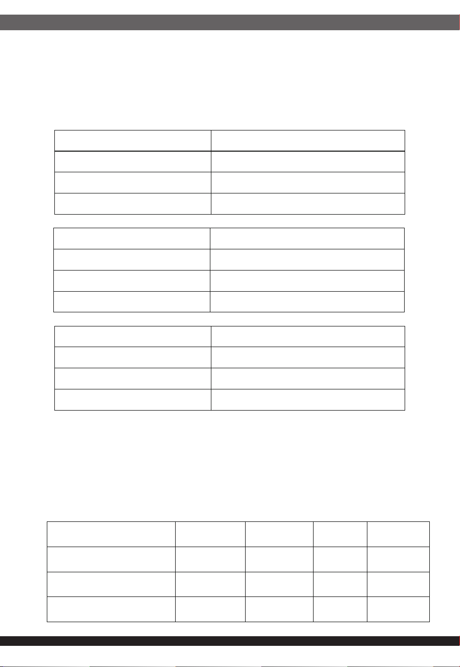
5. ENVIRONMENT
5.1 Operation
5.2 Shipping and Storage
5.3 Altitude
Temperature 0 to 40
o
C
Relative Humidity 10 to 90%, non-condensing
Temperature -40 TO 70
o
C
Relative Humidity
5 to 95%, non-condensing
Operating 20,000FT max
Storage
50,000FT max
08
09
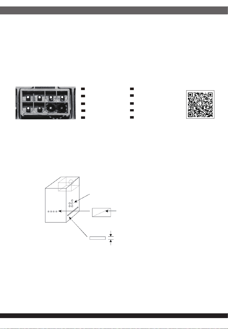
7. POWER SUPPLY CONNECTOR OVERUSE DEFINITION
6. DIMENSION
150x86x140mm
Definition einer Überlastung des
Netzanschlusses
DE
Définition de l'utilisation excessive du
connecteur d'alimentation électrique
FR
Definizione di uso eccessivo del connettore
di alimentazione
IT
Definición de uso excesivo del conector de
la Fuente de alimentación
ES
Определение чрезмерной нагрузки на
коннектор блока питания
RU
電力供給コネクタの使用限度超過に関する説明
JP
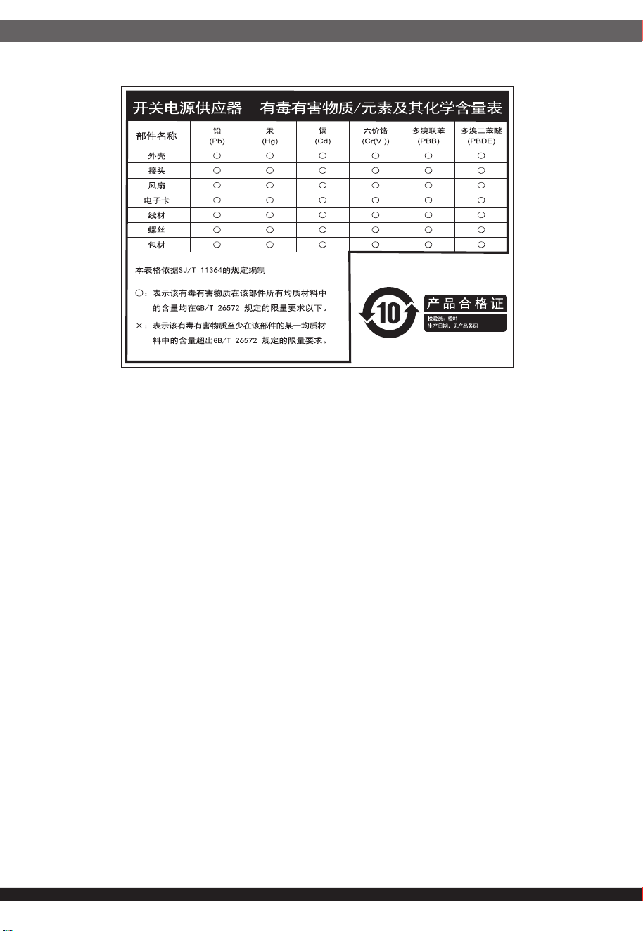
⬉⑤կᑨ఼༈䖛ᑺՓ⫼ᅮН
CN
䳏⑤կឝ఼丁䘢ᑺՓ⫼ᅮ㕽
TW
ขีดจำกัดการรองรับการใช้งานของขั้วต่อจากพาวเวอร์ซัพพลาย
TH
전원 공급 커넥터 과용 정의
KR
⚎њֱ䅋Փ⫼㗙ঞ䰆☿ⱘⳂⱘˈᅝ㺱ℸѸᓣ䳏⑤կឝ఼ᰖˈᖙ䷜ᅝ㺱ᮐヺড়ϟ߫䷙㽕∖ⱘ←Ёˈ
ϺϨᅝ㺱ཹᕠˈᠡৃϞ䳏⑤DŽ
←ᴤ䊾䷜⚎䰆☿←DŽᴤ䋼乏Ў䰆☿DŽ
←ⱘϞᮍঞو䙞П೧ᔶ䭟ᄨˈ᳔ܻᕥϡৃᮐPPDŽ
←ⱘϞᮍঞو䙞П䭋ṱൟ䭟ᄨˈᇡ㾦㎮䎱䲶ϡৃᮐPP˗㢹ᇀᑺᇣᮐPPˈࠛ䭋ᑺϡফ䰤ࠊDŽ
←ᑩ䚼ϡৃ᳝䭟ᄨDŽᑩ䚼ϡৃ᳝ᓔᄨDŽ
ⳈᕥϡᮐPP
ᇡ㾦㎮ϡᮐPP
ᇀᑺᇣᮐPPࠛ䭋ᑺϡ䰤
Openings that do not exceed 1mm in width regardless of length
Openings that do not exceed 5mm in any dimension
ᴀ⫶ક䔌ߎ᳝䱾㛑䞣ˈ⚎䙓ܡ᪡ᰖⱐ⫳䱾ˈ䷜ᮐ㺱ܹ㋏㍅″←Ϻᇛ᠔᳝䀁٭ᅝ㺱ཹ⭊ᕠᠡৃ䭟ଳ䳏⑤DŽ
ᴀ⫶કП䳏⑤䔌ߎ䴲ቀ䳏䰤ࠊൟ䳏⑤ˈ䂟䗷Փ⫼䰆☿←П䙞ˈҹ䙓ܡ☿♑䱾ⱐ⫳DŽ
%60,52+6䊛㿞
KWWSZZZVLOYHUVWRQHWHNFRPGRZQORDGV36856'SGI
10
This device complies with Part 15 of the FCC Rules.
Operation is subject to the following two conditions:
(1) this device may not cause harmful interference, and
(2) this device must accept any interference received,
including interference that may cause undesired operation.
Please refer to SilverStone website for latest specifications updates.
The equipment a Class | Switching Power Supply intended to use
for information technology equipment or Audio and Video equipment.
※付属の電源コードは当該製品専用です。他の機器に使用しないでください。
Model (safety certification): SST-AX0650FCGD-7QH
SST-AX0750FCGD-7QH
SST-AX0850FCGD-7QH
G11255340