
© SIMPLIPHI POWER, INC.
SIMPLIPHIPOWER.COM | 805-640-6700 | BSREV202111121120
1
MODEL NO. 053002
Installaon Manual
BOSS.12
12 Baery Only Storage System
BOSS.12
Not for reproduction

© SIMPLIPHI POWER, INC.
SIMPLIPHIPOWER.COM | 805-640-6700 | BSREV202111121120
2
MODEL NO. 053002
SimpliPhi Your Energy
Security and Independence
and gain control of your own power.
SimpliPhi Power helps you manage your power as a personal resource.
Anytime. Anywhere. SimpliPhi energy storage optimizes integration of any
power generation source – solar, wind, generator – on or off grid, and protects
your home and mission-critical business functions from power outages and
intermittency. SimpliPhi storage technology reduces operating temperature
constraints, toxic coolants and the risk of thermal runaway. Safe lithium ferrous
phosphate (LFP). No cobalt. No toxic hazards.
SimpliPhi’s battery technology utilizes the industry’s most environmentally benign
chemistry (LFP) combined with proprietary architecture and power electronics
(BMS) to create a portfolio of high performance, scalable and enduring energy
storage solutions that provide power security, resilience and daily cycling for
savings on your utility bill – all with a 98% efficiency rate.
SimpliPhi Power offers proprietary, commercially available energy storage and
management systems that are safe, non-toxic, reliable, durable, efficient, highly
scalable, and economical over the lifetime of the PHI Battery.
Not for reproduction

© SIMPLIPHI POWER, INC.
SIMPLIPHIPOWER.COM | 805-640-6700 | BSREV202111121120
3
MODEL NO. 053002
Table of Contents
1.0 – Important Safety Informaon .............................................................................................................. 4
1.1 – Safety Instrucons ............................................................................................................................... 4
1.2 – Limitaons of Use ................................................................................................................................ 5
2.0 – Product Descripon ............................................................................................................................... 5
2.1 – Introducon .......................................................................................................................................... 5
2.2 – Overview ............................................................................................................................................... 5
2.3 – Specicaons ........................................................................................................................................ 6
3.0 – Installaon ................................................................................................................................................ 7
3.1 – Inspecon .............................................................................................................................................. 7
3.2– Unpacking .............................................................................................................................................. 7
3.3 – Required Tools for Installaon .......................................................................................................... 9
3.4 – Installeon Site Locaon ................................................................................................................... 10
3.5 – Clearance Requirements .................................................................................................................... 10
3.6 – Knock-Out Locaon ............................................................................................................................ 11
3.7 – Pad Mounng ....................................................................................................................................... 11
3.8 – Assembling the BOSS.12 Enclosure ................................................................................................ 13
4.0 – Care & Maintenance............................................................................................................................... 18
5.0 – Technical Support .................................................................................................................................... 18
Not for reproduction

© SIMPLIPHI POWER, INC.
SIMPLIPHIPOWER.COM | 805-640-6700 | BSREV202111121120
4
MODEL NO. 053002
CAUTION: DO NOT VOID YOUR WARRANTY- FOLLOW THESE INSTRUCTIONS CAREFULLY AND
REVIEW WARRANTY DOCUMENT PRIOR TO INSTALLATION
1.0 – IMPORTANT SAFETY INFORMATION
1.1 – Safety Instrucons
1. Before assembling or using the SimpliPhi Baery Only Storage System for 12 Baeries (BOSS.12), read all instrucons and
cauonary markings included in this manual.
2. Perform all electrical work on the BOSS.12 Enclosure in accordance with local, state and federal electrical codes.
3. The BOSS.12 Enclosure is NEMA 3R-rated for a degree of protecon against debris, as well as rain, sleet and ice. The
Enclosure is NOT waterght and should therefore be protected against excessive exposure to liquids. For extreme weather
protecon, Rain Hoods are available (RH-1010) and can be ordered with the BOSS.12 Enclosure.
4. To reduce the chance of short-circuits and/or electrical shock, always use insulated tools when installing or working with
this equipment. For the same reason, remove all jewelry such as rings, watches, bracelets, etc., and wear insulated rubber
electrical gloves when installing or performing maintenance on the BOSS.12 Enclosure or the PHI baery modules
contained within.
5. Do not use the BOSS.12 Enclosure if there are indicaons that it has been damaged during shipping or otherwise.
6. Immediately inspect the BOSS.12 Enclosure upon its arrival to the site. Inspect the packaging as well as the BOSS.12
Enclosure itself for signs of rough handling or damage. If there is any evidence of damage, record the damage on the
receiving document before signing for receipt of the equipment. Damage claims should be led directly with the carrier. Not
doing so can limit your ability to claim damage of equipment with the carrier.
7. The BOSS.12 Enclosure is designed for the housing and wiring of up to 12 SimpliPhi PHI 3.8 kWh baeries (measuring
~13.5” wide x 15.5” high with terminals x 8.1” deep). Check with SimpliPhi Technical Support (techsupport@simpliphipower.
com) prior to using the BOSS.12 Enclosure with any other PHI baery models.
8. Prior to installing or performing maintenance on the BOSS.12 Enclosure, turn all included PHI Baery module built-in
circuit breakers’ “ON/OFF” switches to the “OFF” posion, and disconnect all wiring leading from the baeries to the
AccESS fully integrated unit or other Balance of System equipment. Doing so will minimize the risk of shock or sparks during
the baeries’ installaon.
9. Before commissioning the AccESS or BOSS.12 Enclosure with Baeries, PHI baeries MUST be fully charged. Failure to do
so will Void the baeries’ Warranty.
10. In addion to the instrucons outlined in this BOSS.12 Enclosure manual, adhere to all installaon and commissioning
protocols outlined in the PHI Baery Installaon Manual. Failure to do so will Void the baeries’ Warranty.
11. Verify polarity at all baery module connecons with a standard voltmeter before:
A. Energizing the system and,
B. Turning the PHI Baery’s circuit breaker “ON/OFF” switch to the “ON” posion. Reverse polarity at the PHI Baery
terminals will Void the Warranty and destroy the PHI Baeries.
12. Do not operate if the PHI Baery has been damaged in any way during shipping or otherwise.
Not for reproduction

© SIMPLIPHI POWER, INC.
SIMPLIPHIPOWER.COM | 805-640-6700 | BSREV202111121120
5
MODEL NO. 053002
1.2 - Limitaons of Use
The BOSS.6, ExprESS unit and PHI baery modules are not intended for use in connecon with life support systems or other
medical equipment or devices.
2.0 - Product Descripon
2.1 - Introducon
This installaon guide covers the recommended installaon of the BOSS.12 Enclosure. More informaon on SimpliPhi products,
including the SimpliPhi baeries that the BOSS.12 Enclosure is designed to house, can be found on our website: hp://
simpliphipower.com/.
2.2 - Overview
The BOSS.12 Enclosure is intended for the housing and wiring of up to twelve (12) PHI 3.8 kWh deep-cycle Lithium Ferro
Phosphate (LFP) baeries. The Enclosure may be used with the AccESS – Sol-Ark-12K fully integrated units, or as a PHI Baery
enclosure for any other installaon with SimpliPhi-compable equipment.
When the BOSS.12 Enclosure is used with the AccESS fully integrated unit, the Enclosure containing the addional PHI baeries
allows for an increased amount of available energy storage capacity, beyond the three or six PHI Baeries already included in
the fully integrated AccESS unit.
Note that the instantaneous power rang (kW) of the AccESS fully integrated unit is sll limited by the included inverter’s power
rang and/or the 5-point terminal blocks and wiring included with the BOSS.12 Enclosure. Standard wiring typically sold with
the BOSS.12 limits the contained baery bank’s output to a maximum potenal 440 Amps DC connuous. When powering
loads, consider the power rangs of all equipment included in the system, not just the baeries. Also, while the full instantaneous
power from the baery bank may not always be accessible, the baery bank’s full energy storage capacity (kWh) is always
accessible.
As outlined in the PHI Baery Installaon Manual, baeries must always be connected in parallel (Posive
to Posive / Negave to Negave). Any bussing used within the BOSS.12 Enclosure must be used to parallel
the baeries only; no series connecons are permied. Wiring the PHI baeries in series will destroy the
baeries and VOID the Warranty. More detailed connecon instrucons are included in later secons of this
manual.
Not for reproduction

© SIMPLIPHI POWER, INC.
SIMPLIPHIPOWER.COM | 805-640-6700 | BSREV202111121120
6
MODEL NO. 053002
2.3 - Specicaons
Review Table 1.0 below for BOSS.12 Enclosure specicaons, including physical dimensions, Warranty period and technical
data. See Table 2.0 for abbreviated specicaons on the PHI 3.8 kWh baeries included in the BOSS.12 Enclosure; refer to the
“Specicaon Sheets” secon of SimpliPhi’s Product Documentaon web page for addional details.
Table 1.0 – BOSS.12 Enclosure Specicaons
Table 2.0 – PHI 3.8 Baery Specicaons (NOT included with BOSS.12 Enclosure)
BOSS.12 Enclosure
WEIGHT 428 lbs. (194.138 kg.) Without Baeries
DIMENSIONS 29.5” W x 76”H (w/feet) x 20” D / 75 cm W x 193 cm H (w/feet) x 51 cm D
MOUNTING Free Standing or Pad Mounted
WARRANTY PERIOD 5 Years
INTERCONNECTING BUSBARS’
AMPACITY
500 - 599 Amps DC
DC CONNECTIONS 2 X 5-Point Terminal Blocks, 3/8” lugs, 650 Amps DC
PHI 3.8 48V
WEIGHT 86 lbs. (39 kg.)
DIMENSIONS
13.5” W x 14” H (15.5” w/terminals) x 8” D / 0.88 3
(34.3 cm x 35.6 cm x 20.3 cm / 0.025 m3)
DC VOLTAGE - NOMINAL 51.2 VDC
AMP HOURS 75 Ah
RATED kWh CAPACITY @ C/2
3.8 kWh at 100% DOD
3.04 kWh at 80% DOD
MAX Discharge Rate (10 minutes) 80 Amps DC (3.07 kW DC)
MAX Connuous Charge & Discharge Rate 37.5 Amps DC (1.92 kW DC)
OPERATING TEMPERATURE -4°F to 140°F (-20°C to 60°C)
CHARGING TEMPERATURE 32°F to 120°F (0°C to 49°C)
WARRANTY PERIOD 10 Years
Not for reproduction
© SIMPLIPHI POWER, INC.
SIMPLIPHIPOWER.COM | 805-640-6700 | BSREV202111121120
7
MODEL NO. 053002
3.0 - Installaon
3.1 - Inspecon
Immediately inspect the BOSS.12 Enclosure upon its arrival to the site. Inspect the packaging as well as the BOSS.12 Enclosure
itself for signs of rough handling or damage. If there is any evidence of damage, record the damage on the receiving document
before signing for receipt of the equipment. Damage claims should be led directly with the carrier. Not doing so can limit your
ability to claim damage of equipment with the carrier.
3.2 - Unpacking
Aer the shipment’s inspecon is completed, perform the following steps to unpack the equipment:
1. Open all cartons.
2. Compare the items received against the packing list to see if any items are missing. If an item is missing or damaged, contact
SimpliPhi Power (805-640-6700).
3. Remove all packing materials, envelopes, and boxes from the cartons. Keep all packing materials and cartons in case you
need to transport or ship the unit at a later date.
The BOSS.12 Enclosure shipment includes the following items, listed in Table 3.0 on the following page.
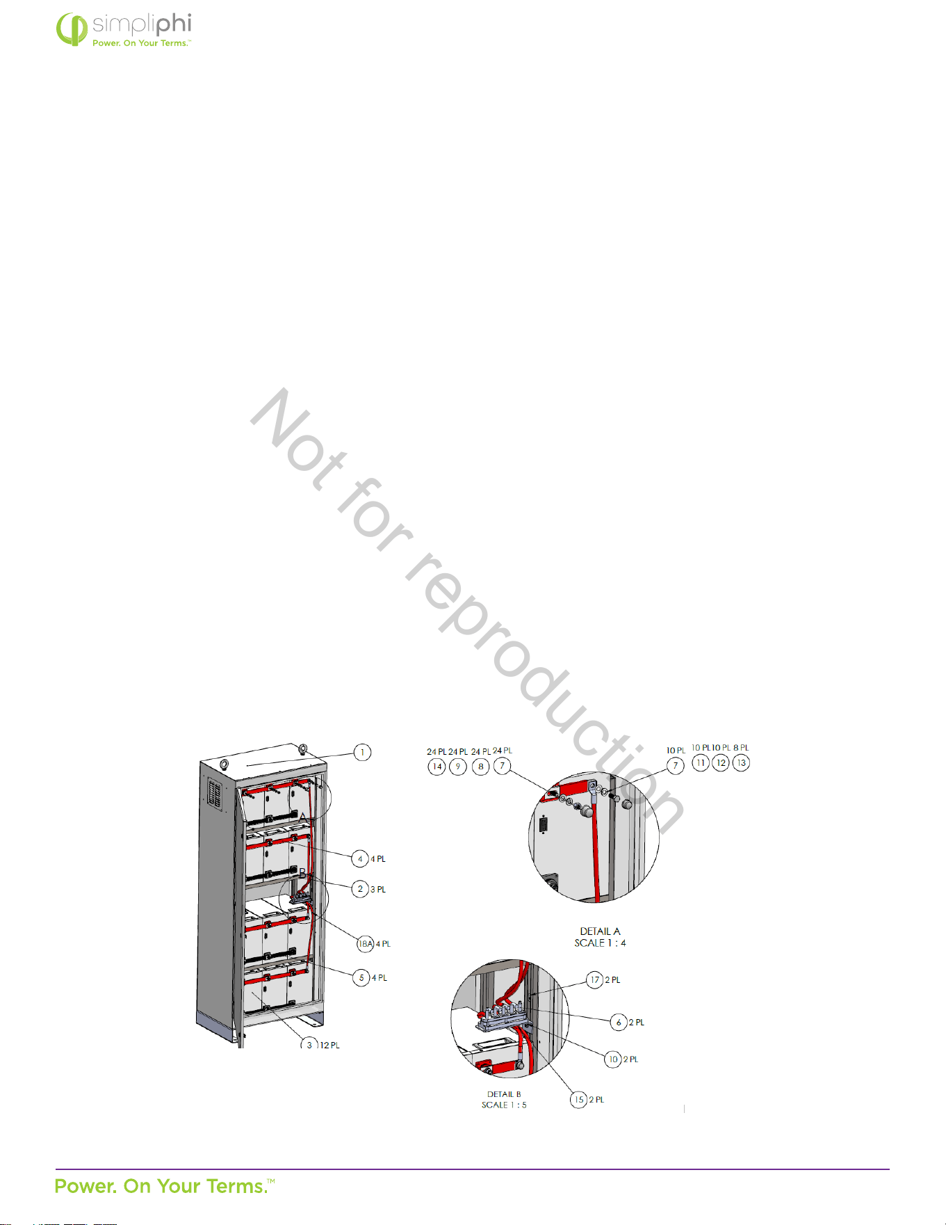
Refer to Figure 1 on the follow page for a visual depicon of the BOSS.12 Enclosure’s assembled internal layout with the
maximum number of addional PHI 3.8, 3.5, or 3.4 kWh baeries included — 12.
Figure 1 – Assembled AccESS Enclosure with 12 PHI Baeries (Refer to Tables 3 & 4 for Key)
Not for reproduction

© SIMPLIPHI POWER, INC.
SIMPLIPHIPOWER.COM | 805-640-6700 | BSREV202111121120
8
MODEL NO. 053002
Table 3 – Items Included in the BOSS.12 Shipment
Item
Number
Descripon Quanty
1 BOSS.12 Carbon Steel Enclosure with Built-In Fan and Thermal Sensor 1
2 Built-In 0.125” Carbon Steel Shelves 3
6 5-Point Terminal Block, 3/8” lugs, 650 Amps DC 2
7
3/8” Brass Washer
(not included with the BOSS.12 enclosure; included with busbars)
up to 32 (4 per busbar)
10 ¼”-20½”-long Steel Hex Head Screw 2
15 Marinco Busbar Bracket 2
16 3” Wide Pre-Installed Polypropylene Bar 2
17 ¼”-20 Threaded Strut Channel Nut with Spring 2
NP 96”-long 4/0 cables with 3/8” lugs (one negave, one posive) 2
Not Included
The BOSS.12 Enclosure shipment does not include interconnecng baery busbars, baery cables, or conduit. Busbar Kits can
be ordered from SimpliPhi or any SimpliPhi Distributor based on the guidance provided in Table 5.
The following list of items are recommended for complete BOSS.12 assembly but are not included with the BOSS.12 original
purchase.
Table 4 – Items Not Included in the BOSS.12 Original Purchase
Item
Number
Descripon Quanty
3 PHI 3.8 kWh Baery (Sold and Shipped Separately) up to 12
4 21.5”-long Posive Copper Busbar (Sold Separately) up to 4 (1 per 3-baery set)
5 19.5”-long Negave Copper Busbar (Sold Separately) up to 4 (1 per 3-baery set)
7 3/8” Brass Washer up to 32 (4 per busbar)
8 3/8” Stainless Steel Lock Washer up to 24 (2 per baery)
9 11/16” Stainless Steel Nut up to 24 (2 per baery)
11 3/8” Brass Lock Washer up to 8 (1 per busbar)
12 3/8”-16½”-long Brass Hex Head Screw up to 8 (1 per busbar)
13 Hex Nut Cap for 35/64” Wide Nut up to 8 (1 per busbar)
14 Hex Nut Cap for 43/64” Wide Nut up to 24 (3 per busbar)
Not for reproduction

© SIMPLIPHI POWER, INC.
SIMPLIPHIPOWER.COM | 805-640-6700 | BSREV202111121120
9
MODEL NO. 053002
Interconnecng busbars for paralleling two or three PHI baeries (SKU numbers BB-2-12 and BB-3-12, respecvely) may
be purchased from any SimpliPhi distributor: hps://simpliphipower.com/distributors/. All baeries contained within the PHI
baery bank must be idencally grouped (i.e. do not use both the BB-2-12 and BB-3-12 products within the same PHI baery
bank). This presents limitaons when wiring fewer than 12 PHI baeries in the BOSS.12 enclosure:
Table 5 – Recommended Baery Bussing and Cabling within the BOSS.12
Terminal block-to-inverter cables are included with the BOSS.12 purchase. SimpliPhi typically uses two (one posive, one
negave), 96”-long 4/0 Arcc Ultraex Blue® cables with 3/8” lugs included (one lug on each end of the cable), for connecng
between the terminal block and the inverter’s DC busbars or plates.
Note: Arcc Ultraex Blue® cables are rated according to the specicaons listed at this link:
hp://www.polarwire.com/properes-specs.pdf.
• Arcc Ultraex Blue® 2/0 AWG cable has a 325 Ampacity rang at 86°F (30°C)
• Arcc Ultraex Blue® 4/0 AWG cable has a 440 Ampacity rang at 86°F (30°C)
3.3 - Required Tools for Installaon
The following tools are required to assemble the BOSS.12 Enclosure:
• Torque Wrench
• 9/16” Socket
• 11/16” Socket
• 17mm Socket
• Protecve Wear
Number of PHI
Baeries
Recommendaon
12
Order 4 x BB-3-12 busbar sets (4 posive, 4 negave) and 8 total 45”-long 2/0 Arcc Ultraex Blue®
cables with 3/8” lugs included (4 posive, 4 negave).
11 Not supported, consider purchasing addional baery.
10 Not supported, consider purchasing addional baeries.
9
Order 3 x BB-3-12 busbar sets (3 posive, 3 negave) and 6 total 45”-long 2/0 Arcc Ultraex Blue®
cables with 3/8” lugs included (3 posive, 3 negave).
8
Order 4 x BB-2-12 busbar sets (4 posive, 4 negave) and 8 total 45”-long 2/0 Arcc Ultraex Blue®
cables with 3/8” lugs included (4 posive, 4 negave).
7 Not supported, consider purchasing addional baery.
6 or fewer
Use the BOSS.6 or follow BOSS.6 wiring guidance if considering expansion beyond 6 baeries in the
future.
CAUTION: The two (one posive, one negave) 4/0 AWG Arcc Ultraex Blue cables (each rated at 440A)
typically sold with the BOSS.12 will not suce when taking advantage of the FULL instantaneous connuous
current output of all 12 PHI baeries (450ADC combined).
Not for reproduction
© SIMPLIPHI POWER, INC.
SIMPLIPHIPOWER.COM | 805-640-6700 | BSREV202111121120
10
MODEL NO. 053002
3.4 - Installaon Site Locaon
The BOSS.12 Enclosure may be installed indoors or outdoors mounted onto a concrete pad. The cabinet is rated for NEMA-
3R use: moisture-resistant, but should be kept away from excessive moisture, mist, rain or wetness. For extreme weather
protecon, Rain Hoods are available (RH-1010) and can be ordered with the BOSS.12 Enclosure.
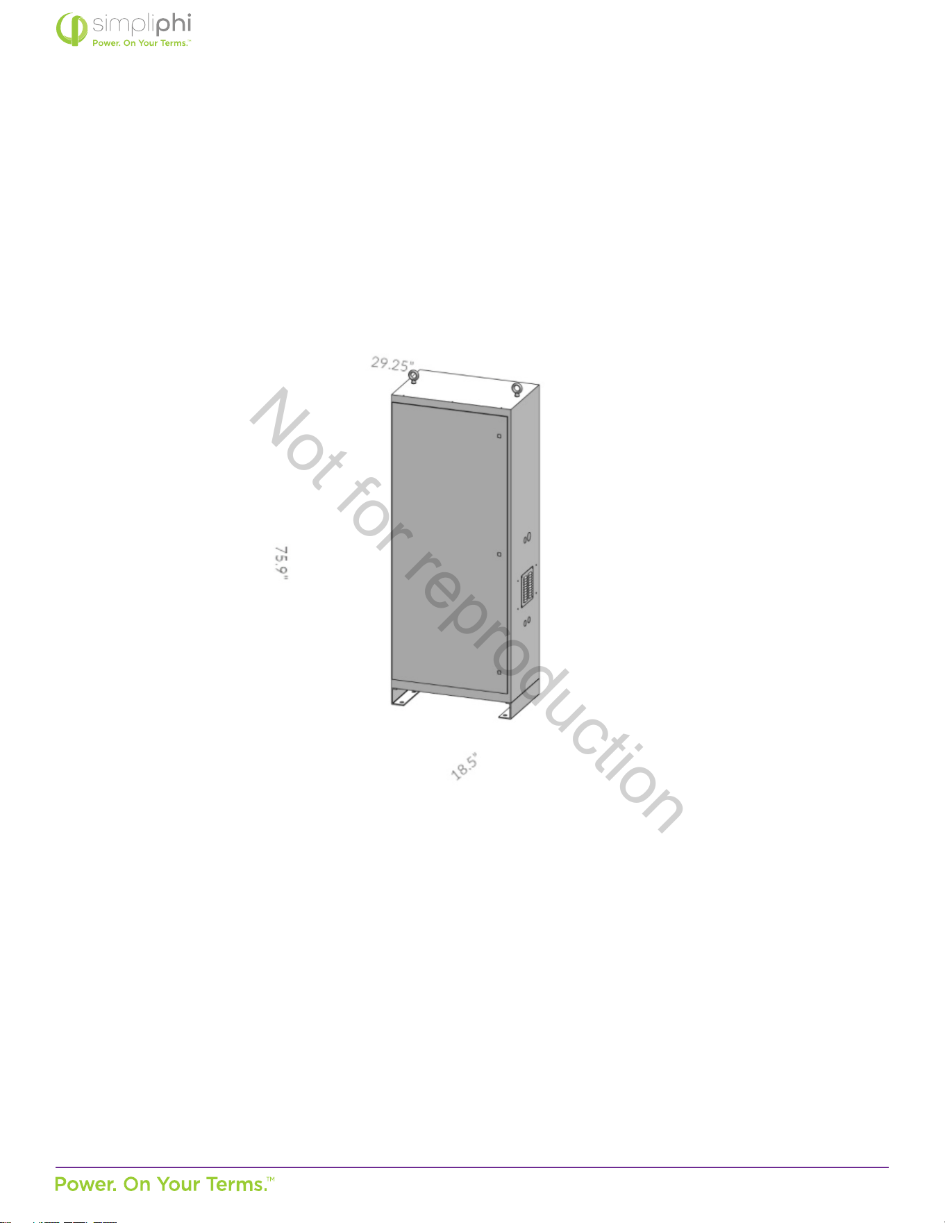
Keep the BOSS.12 Enclosure isolated from ammable materials or vapors.
Figure 2 - BOSS.12 Enclosure dimensions
3.5 - Clearance Requirements
The BOSS.12 Enclosure can be installed directly adjacent to the AccESS fully integrated unit. No clearance is required between
the two units. However, allow 3 feet of clearance in front of the BOSS.12 Enclosure and/or AccESS unit, and 3 inches of
clearance on the external sides of the BOSS.12 Enclosure and AccESS.
Not for reproduction
© SIMPLIPHI POWER, INC.
SIMPLIPHIPOWER.COM | 805-640-6700 | BSREV202111121120
11
MODEL NO. 053002
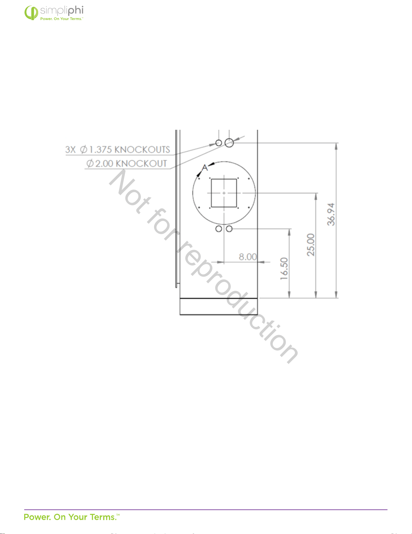
3.6 - Knock-Out Locaon
Three, 1.375-inch OD knockouts and one, 2-inch OD knockout are located on both sides of the BOSS.12 Enclosure. They can be
used for roung the two 4/0 baery cables from the enclosure to the inverter’s power panel (explained in greater detail on page
12, #18 of this manual). Not all knockouts must be used.
Figure 3 – BOSS.12 Enclosure Knockouts (sides)
3.7 - Pad Mounng
The BOSS.12 Enclosure must be installed and secured on level concrete. For a pre-cast concrete pad, a 4” minimum thickness is
required.
The AccESS fully integrated unit and BOSS.12 Enclosures are not suited for wall mounng. Any aempt to wall-mount the unit
will Void the Warranty.
Six 1-inch knockouts are located in the base of the BOSS.12 Enclosure for tool accessibility when mounng the BOSS.12
Enclosure to the concrete pad. Cover knockout holes with sealing tape aer pad mount installaon, and prior to installing the
PHI Baeries into the base of the cabinet.
Secure the BOSS.12 Enclosure to the concrete with concrete anchors, such as threaded rods, masonry bolts, or carriage bolts,
minimum ½” diameter. See Figure 4 and Figure 5 for details.
Not for reproduction
© SIMPLIPHI POWER, INC.
SIMPLIPHIPOWER.COM | 805-640-6700 | BSREV202111121120
12
MODEL NO. 053002
Figure 4 – BOSS.12 Enclosure Knockouts (boom)
Figure 5 – BOSS.12 Enclosure Knockouts (boom)
Not for reproduction
© SIMPLIPHI POWER, INC.
SIMPLIPHIPOWER.COM | 805-640-6700 | BSREV202111121120
13
MODEL NO. 053002
3.8 - Assembling the BOSS.12 Enclosure
4. The shelf mounng heights in the BOSS.12 Enclosure are pre-congured to accommodate the PHI baeries. Adjusng the
shelves’ locaons is not necessary.
5. Make sure all PHI Baery module circuit breakers are in the “OFF” posion. Prepare the baery modules for installaon by
removing all plasc terminal covers, 11/16” stainless steel hex nuts and 3/8” lock washers from the baeries’ terminals and
set aside.
6. Conrm that the polypropylene bars pre-assembled in the BOSS.12 enclosure are secure.
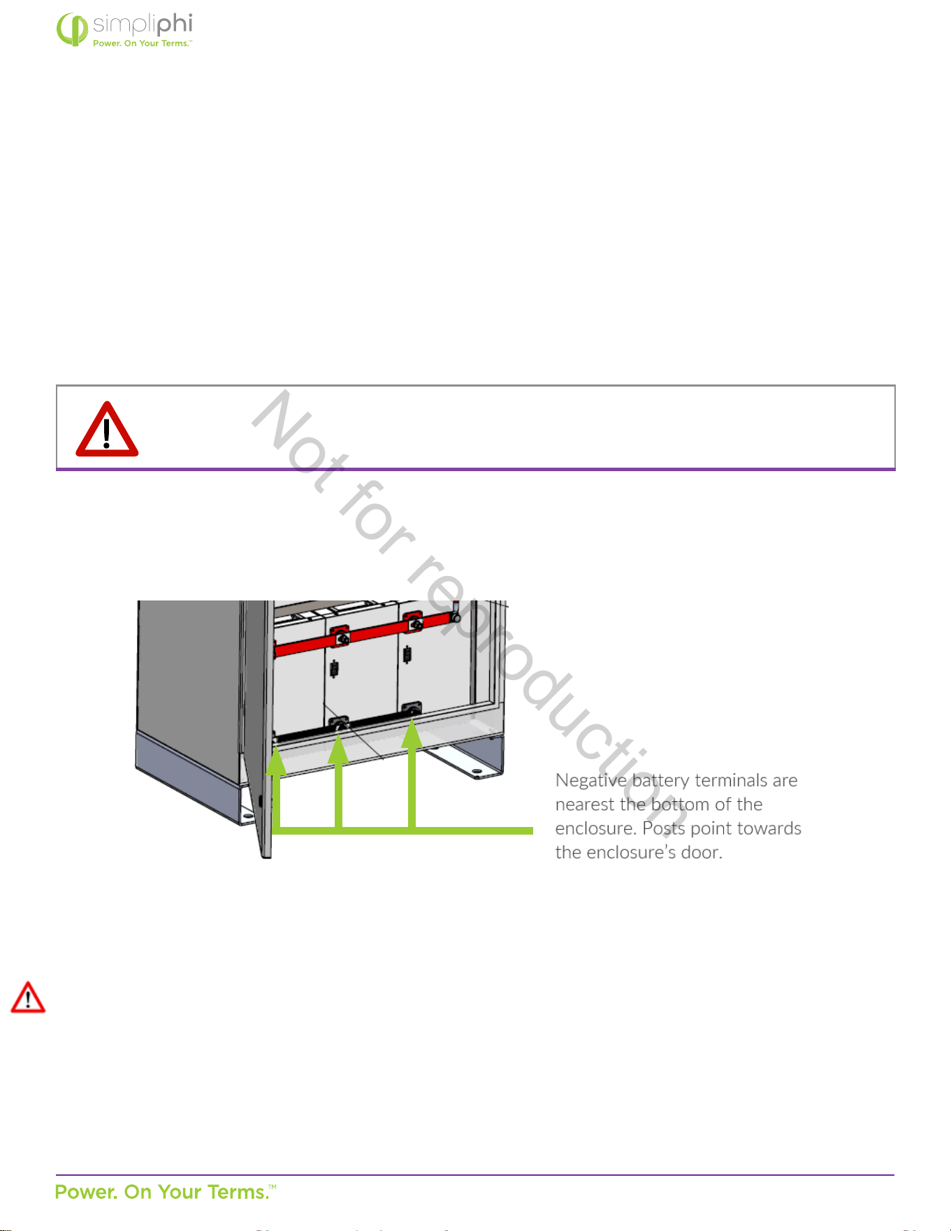
7. Install the PHI Baery modules in the enclosure starng at the boom of the enclosure.
8. Arrange up to three PHI Baery modules on each shelf. Orient the modules so that the baery terminals point forward
toward the door, with the negave posts nearest the boom of the enclosure (see Figure 5 on page 12).
Figure 6 – PHI Baery Module Arrangement in the BOSS.12 Enclosure
9. Connue arranging the PHI Baery modules on the remaining shelves.
10. Aer securely placing all the PHI Baery modules in the BOSS.12 Enclosure, conrm that all the module circuit breakers
are sll in the “OFF” posion.
11. Arrange the horizontal negave (black) interconnecng copper busbars onto the baeries’ negave terminals. Secure the
busbars to the baeries using the 3/8” at washers (included with the busbars), 3/8” stainless steel lock washers and 11/16”
stainless steel hex nuts (originally included on the baeries) to secure the busbars directly to the baeries’ terminals, and
ghten to 160 in-lbs.
CAUTION: Do not aempt to loosen the large brass nut at the base of the baery terminals.
Doing so will Void the Warranty
Not for reproduction
© SIMPLIPHI POWER, INC.
SIMPLIPHIPOWER.COM | 805-640-6700 | BSREV202111121120
14
MODEL NO. 053002
12. Aach the horizontal posive (red) interconnecng copper busbars onto the baeries’ posive terminals. Use the 3/8”
at washers (included with the busbars), 3/8” lock washers and 11/16” stainless steel hex nuts (originally included on the
baeries) to secure the busbars directly to the baeries’ terminals, ghtening the nuts to 160 in-lbs. (see Figure 6 on page
13)
Figure 7 – Interconnecng Busbars Aach Directly to PHI Baery Terminals
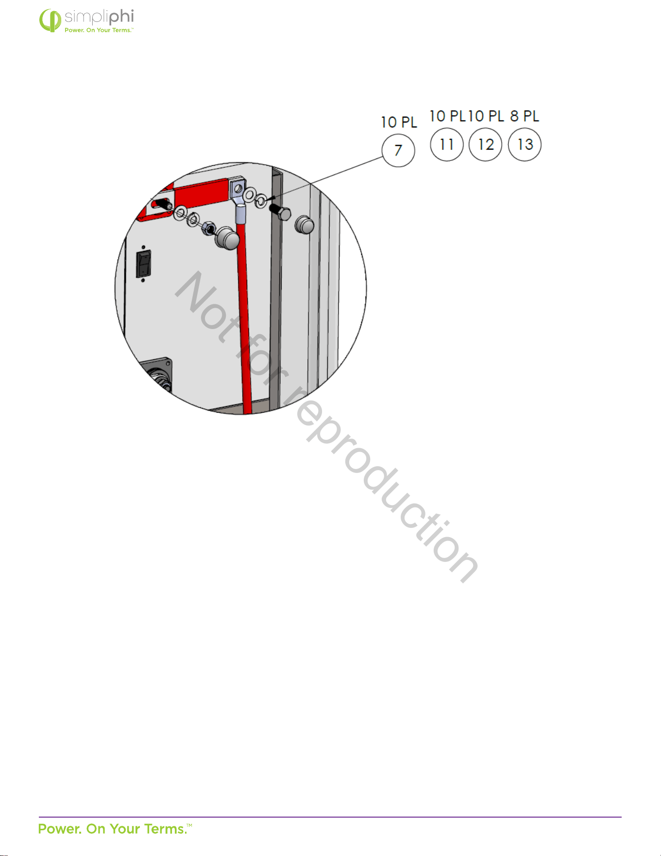
13. Wire each of the four (4) 45”-long 2/0 Arcc Ultraex Blue® negave cables to the connecon points located on each of the
ends of the four (4) negave busbars. Use the 3/8” at washers, 3/8” brass lock washers and 3/8”-16½”-long brass hex head
screws (included with the busbars) to secure the 2/0 cables to each of the busbars, and ghten to 120 in-lbs.
14. Wire each of the four (4) 45”-long 2/0 Arcc Ultraex Blue® posive cables to the connecon points located on each of the
ends of the four (4) posive busbars. Use the 3/8” at washers, 3/8” brass lock washers and 3/8”-16½”-long brass hex head
screws (included with the busbars) to secure the 2/0 cables to each of the busbars, and ghten to 120 in-lbs.
CAUTION: Do not place any material (such as a washer) between the large brass nut at the base of the
baery terminal and the interconnect.
(Refer to the Connecng a busbar to terminals on a SimpliPhi baery video.)
Not for reproduction
© SIMPLIPHI POWER, INC.
SIMPLIPHIPOWER.COM | 805-640-6700 | BSREV202111121120
15
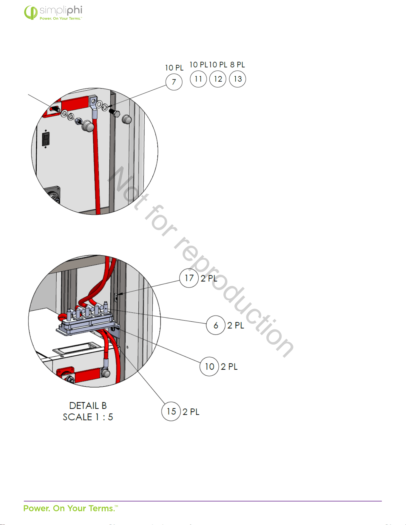
MODEL NO. 053002
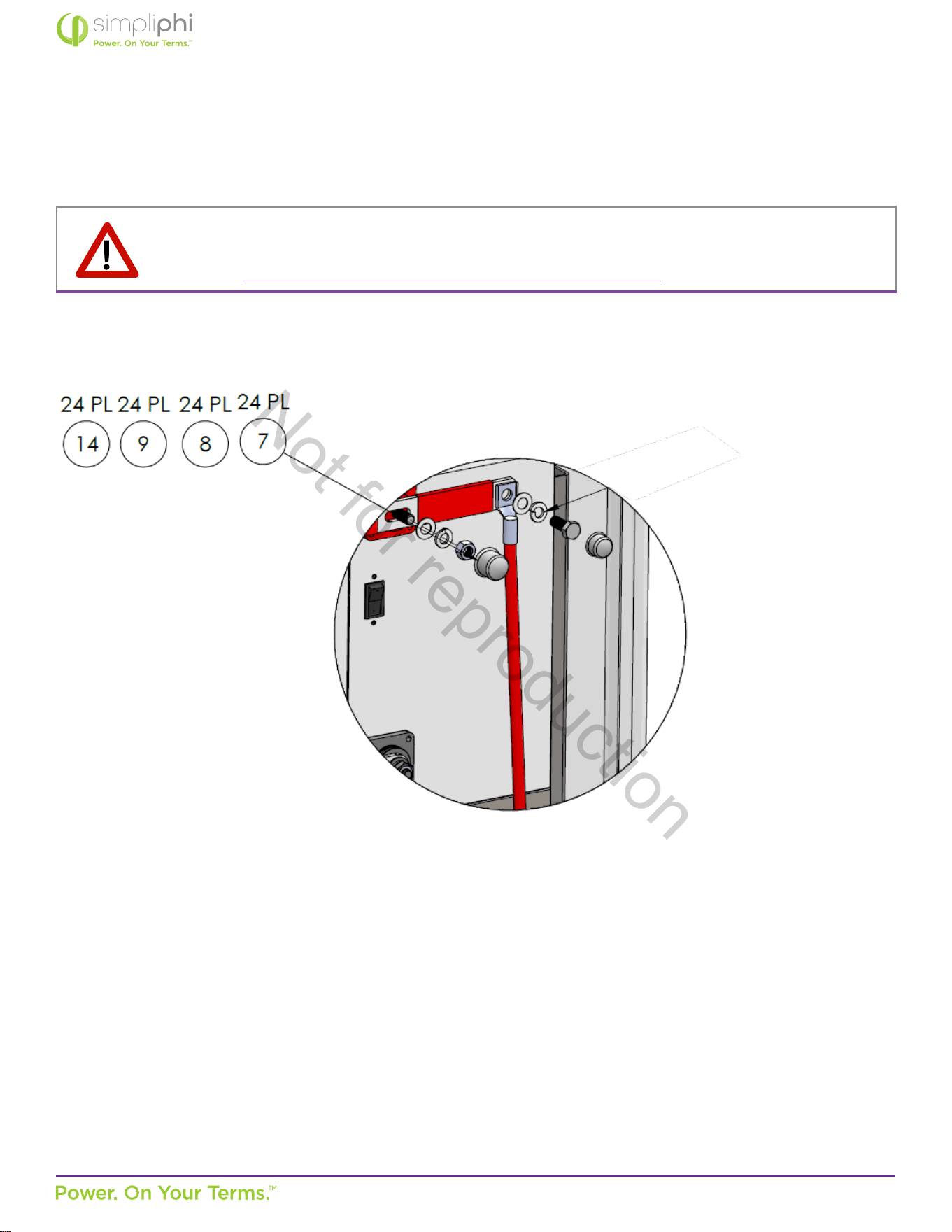
Figure 8 – 2/0 Cables Aach to ends of the Interconnecng Busbars
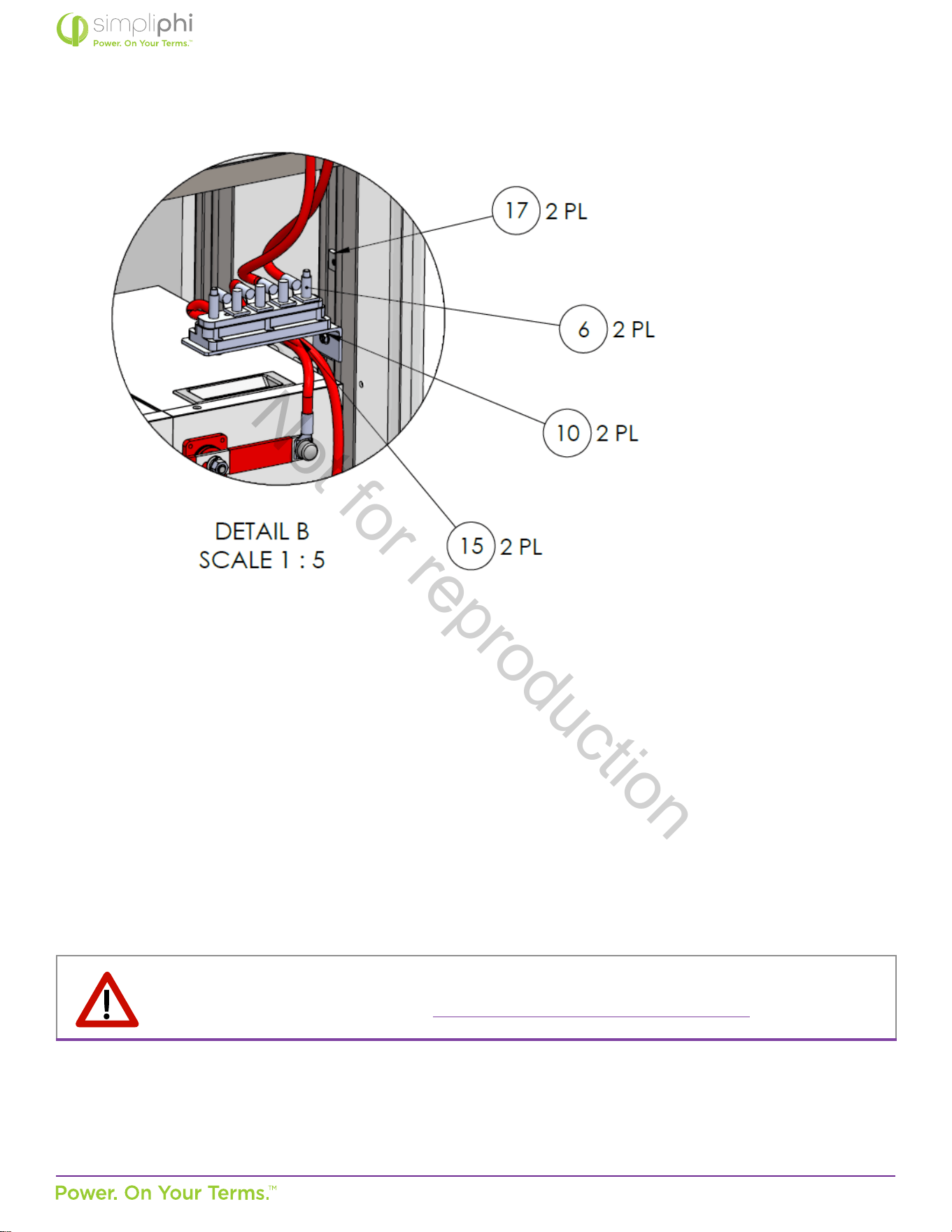
15. Land the four (4) 2/0 negave cables on four connecon points on the negave 5-point terminal block (located on the
installer’s le, when facing the enclosure*) using a 17mm wrench socket to ghten the ¼”-20 nuts. Tighten to a torque value
of 120 in-lbs.
16. Land the four (4) 2/0 posive cables on four connecon points on the posive 5-point terminal block (located on the
installer’s right, when facing the enclosure*) using a 17mm wrench socket to ghten the ¼”-20 nuts.* Tighten to a torque
value of 120 in-lbs.
*It is important to maintain the block on the installer’s le, when facing the enclosure, as the negave terminal block, and maintain
the block on the installer’s right, when facing the enclosure, as the posive terminal block, due to the BOSS.12’s fan coming pre-wired
to the terminal blocks within the unit.
Not for reproduction
© SIMPLIPHI POWER, INC.
SIMPLIPHIPOWER.COM | 805-640-6700 | BSREV202111121120
16
MODEL NO. 053002
Figure 9 – 2/0 Cables Wiring from Busbars to Terminal Blocks
17. Wire the PHI baery bank contained in the BOSS.12 to the inverter or inverter’s power panel
• Connect the 8- negave (black) 4/0 cable to the negave 5-point terminal busbar.
Tighten to a torque value of 120 in-lbs.
• Connect the 8- posive (red) 4/0 cable to the posive 5-point terminal busbar.
Tighten to a torque value of 120 in-lbs.
• Route the two 4/0 cables (included with the BOSS.12) conduit, using the desired knockouts on the side of the BOSS.12
enclosure to the inverter or inverter’s distribuon panel in the adjacent equipment or AccESS fully integrated unit.
• To access the DC negave and DC posive busbars or plates in the accompanying inverter’s distribuon panel, remove
the distribuon panel cover.
• Land the 8- negave (black) 4/0 cable on the DC negave bus or plate and the posive (red) 4/0 cable on the DC posive
bus or plate (see Figure 9 below).
• Re-aach the inverter’s distribuon panel cover.
18. Set the circuit breakers for all PHI baery modules to the ON posion.
This completes the installaon procedure for the BOSS.12 Enclosure.
CAUTION: Turn the inverter’s main DC Disconnect on only AFTER ALL the built-in circuit breakers in the PHI
Baery bank are turned on. (Refer to the System Commissioning SimpliPhi baery video.)
Not for reproduction

© SIMPLIPHI POWER, INC.
SIMPLIPHIPOWER.COM | 805-640-6700 | BSREV202111121120
17
MODEL NO. 053002
4.0 - Care and Maintenance
The BOSS.12 Enclosure is designed to deliver many years of reliable service in a wide variety of environments. The BOSS.12
Enclosure is resistant to most environmental elements, but should be isolated from excessive water or moisture, extreme heat,
solvents, ammable materials, and environmental hazards.
If the BOSS.12 Enclosure becomes dirty or grimy, wipe it as you would any kitchen cabinet. Do not use a pressure washer or
hose to clean the BOSS.12 Enclosure.
5.0 - Technical Support
For technical support related to your BOSS.12 Enclosure, please contact us as at:
805-640-6700
techsupport@simpliphipower.com
Remember, all Balance of System equipment must be programmed to SimpliPhi’s specied sengs and PHI
baeries must be fully charged before commissioning the system (i.e. before connecng the baeries to any
loads).
Not for reproduction