E-Bike
PRODUCT INSTRUCTION
MANUAL
Caution : Please read the manual before your rst ride!

CONTENTS
01 SAFETY INSTRUCTION
03 GENERAL INFORMATION
07 BIKE USAGE
09 INSTALLATION AND ADJUSTMENT
18 METER OPERATION
26 BATTERY AND CHARGING
29 MAINTENANCE
30 WARRANTY
31 ATTACHMENT
33 WARNING

01
Things To Know Before Use
Do not use the product before carefully reading the instructions from
this manual and understanding the performance of the item;
Don't lend this product to people who can't operate it, so as not to cause
harm; if you lend the bike, please let the user follow instructions, it could
help to decrease the risk of accident;
The E-bike cannot be used as o-road vehicles or used for extreme
bicycle sports; when riding the bicycle, please wear a safety helmet and
protective gear. It is forbidden to ride with one hand;
Please abide by the trac rules and prohibit riding on motorized lanes
and roads withmultiple pedestrians;
Carry people or objects in accordance with the requirements of laws and
regulations, and do not park in the building's lobby, evacuation stairs,
walkways, and safe entrances and exits;
It is recommended to charge and park in an outdoor dedicated parking
hall, while avoiding rain; when charging, keep away from combustibles,
and the charging time should not be too long ;
For safety reasons, please do not change the default speed setting of the
electric bicycle and do not exceed speed limit in accordance with the
trac rule. Riding on non-motorized lanes, downhills and paved roads
not exceeding 15km/h;
●
●
●
●
●
●
●
Thank you for choosing our products.
To ensure your safety and health, we encourage you to read this manual
thoroughly before you assemble the bike and take the rst ride. Safe and
eective use can only be assured if the equipment is assembled, maintained,
and used properly. More importantly, this will oer you a general
understanding and get the most out of your bike. Please check your electric
bike before every ride, especially when traveling long distances.
This manual is intended as a general guide to your new e-bike. For technical
support, including repair information, please consult your dealer.
SAFETY INSTRUCTION

02
SAFETY INSTRUCTION
When adjusting the handlebar or saddle, please be careful not to exceed
the safety line markings on the handlebar and saddle;
Please check the tire pressure before riding, the recommended tire
pressure is 35-45PSI;
Please check the power circuit, lighting circuit, etc. before riding;
Before riding, please check whether the front and rear brakes work
normally, check the fastening status of the handlebars and front and rear
wheels, and check whether the reector is damaged or contaminated;
When using the motor, please be careful not to hit vigorously and keep
the rotating shaft lubricated;
Try to avoid traveling in severe weather such as heavy rain;
Riding in rain or snow, the braking distance will be extended, pay
attention to slow down;
It is not allowed to exceed the maximum load of the vehicle body when
riding(the maximum load is 120KG);
It is suitable for people of 16+ years old and physically fit adults, and
it is strictly forbidden to drive electric bicycles on the road by people
under 16 years old.
●
●
●
●
●
●
●
●
●

03
GENERAL INFORMATION
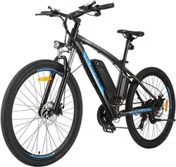
1. About ANCHEER Electric Bike
ANCHEER electric bike is a leading icon of e-bikes. For years, ANCHEER
has been not only dedicating to innovation, cutting-edge technology and
premium materials, but also providing cost eective e-bikes, to satisfy
riders' various needs of transportation and even desire of exploring sports &
outdoors life. Just ride freely with ANCHEER!
2. What’s In the Box (Parts List)
Description Quantity
ANCHEER Electric Bike
Pedal 2
1
User Manual
Saddle 1
1
Key
Saddle Tube
Tools Bag
1
1
2
Charging Adapter
Kickstand
Stem
Throttle
Rear Rack
Bell
1
1
1
1
1
1
Battery
Front Fender 1
1
04
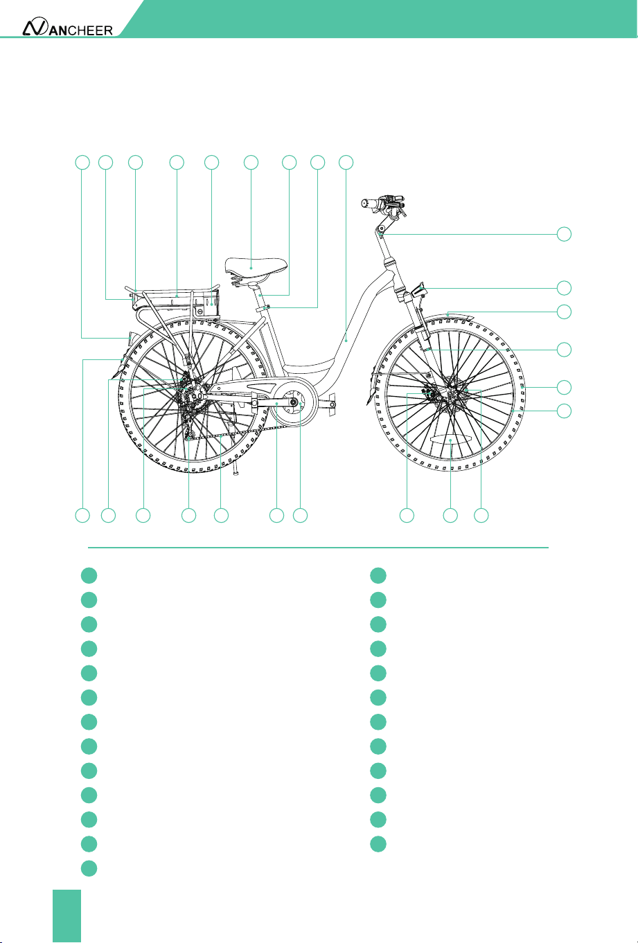
GENERAL INFORMATION
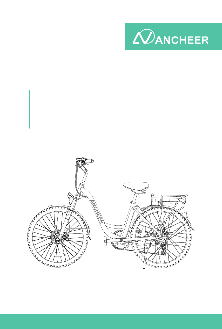
3. Bike Components
Rim
Battery
Front Fork
Rear Light
Rear Reector Lamp
Tyre
Rear Rack
Front Fender
Head Light/Front Light
Rear Fender
Stem
Rear Disc Brake Callipers
Flywheel
Rear Derailleur
Frame
Chain
Seat Post Clamp/ Seat Clamp
Crank
Saddle Post/ Seat Tube
Chain Wheel
Saddle
Front Disc Brake Calipers
Disc
Wheel Reector
Controller
1
13
2
14
3
15
4
16
5
17
6
18
7
19
8
20
9
21
10
22
11
23
12
24
25
1
2
711 1012131415
16 17 18 19 20 21 22 23 24 25
9 8
4
3
5
6
05
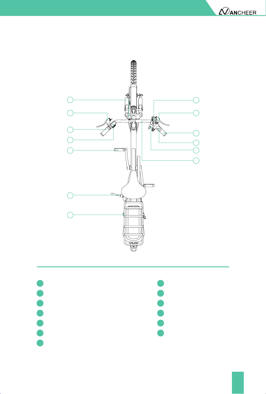
GENERAL INFORMATION
Front Reector Rear Shifter
Left Grip Right Grip
Left Brake Lever Right Brake Lever
Meter Throttle/ Twister
Pedal Bell
Kick Stand
Motor
Handle Bar
26 33
27 34
28 35
29 36
30 37
31
32
38
29
28
30
31
32
27
26
34
36
37
38
35
33
06
General Information
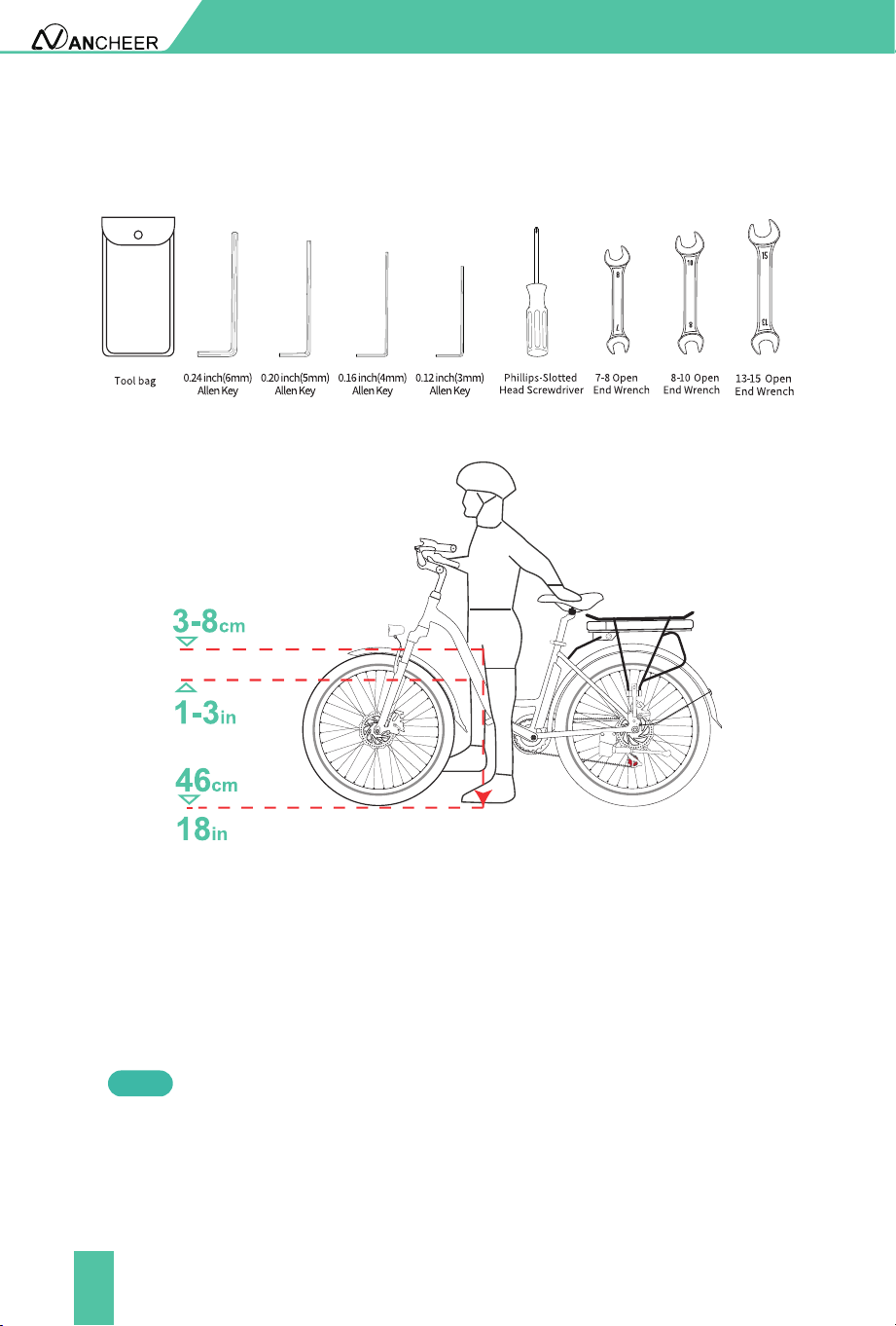
4. Tool list
5. Standover Height
For the sake of safety and comfortable riding, when the rider stands on the
ground there should be clearance of 46cm/18in from ground to the crotch of
the rider. Also, at least 3-8cm/1-3in between the crotch and the top tube of
the bike.
Standover height does not apply to bicycles with step-through frames.
Instead, the limiting dimension is determined by saddle height range. You
should adjust your saddle position without exceeding the limit line on the
saddle tube.
Note

07
BIKE USAGE
Before Riding
During Riding
Before riding the bike on the open road, try all the settings on the electric
bike, and get used to various results in a safe and controllable environment.
Please check the power circuit, lighting circuit, and test the brake system
before cycling.
Always check the tire pressure before starting to ride, and make sure that
the tire is inated to a pressure within the specied range.
In order to ensure the safety of riding, please check regularly for loose
parts or screws. The places that need to be checked include but not limited
to the seat tube, wheels, handlebars and pedals.
If necessary, please conrm whether the battery capacity can meet you
riding demand.
2
1
If the pressure exceeds the recommended maximum value, the tire
may blow out of the rim, which may damage the bicycle and cause
injury to the cyclist and nearby people.
If the pressure is too low, the wheel may be damaged, or the inner
tube may be squeezed, causing the tire to leak air.
Please wear helmets and riding gear that meet the requirements in
accordance with regulations.
Avoid traveling in severe weather such as heavy rain and snow, etc.
Carry people or objects in accordance with the requirements of laws and
regulations, and the load of the entire bike should not exceed 120kg.
Obey the trac rules.
●
●
●
●
●
●
●
●
●
After Riding
After heavy use, do not touch the hot surface, such as the disc brake rotor or
the side edge of the brake rim.
When folding the kickstand, always make sure that the stand is secure and
the base is rm to prevent the bicycle from falling.
If the bicycle is splashed with moisture, please wipe it dry and clean in time.
●
●
●
08
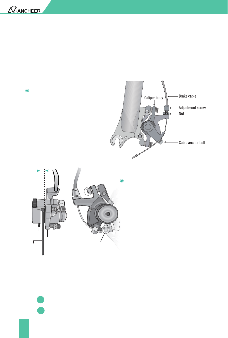
Brake Adjustment
If the brake is not sensitive, loosen
the anchor bolt of the brake cable
to shorten the brake distance of the
brake cable and then tighten the
bolt. Or, lengthen the distance of
the brake cable when the brake is
too sensitive.
If the rotor always rubs against
the brake pad or the gap is too
large, loose the two centering
adjustment screws, but do not
remove them. Slowly rotate
the wheel and check the space
between the rotor and the brake
pad; adjust the position of the
brake pad and the rotor. Centering
the rotor and the pads to avoid
friction. After the adjustment is
complete, tighten the screws.
Ensure that the brake cables are properly inserted into the brake levers
before aligning a mechanical disc brake. If the disc rotor is bent or damaged,
replace the rotor rst.
Leave the same clearance on
both sides of the disc rotor
Brake pad
Disc rotor
Adjust caliper
to center the
rotor
Centering
adjustment
screws
BIKE USAGE
Shifting Recommendations
In order to increase the range, we recommend shifting according to the
speed.
For starting and low-speed riding, it is best to use a low-speed gear.
At higher speeds, a higher gear should be selected.
2
1
09
Open the package of the bike, take out the electric bike and all the accessories
inside and use the tool to cut o the packing rope.
INSTALLATION AND ADJUSTMENT
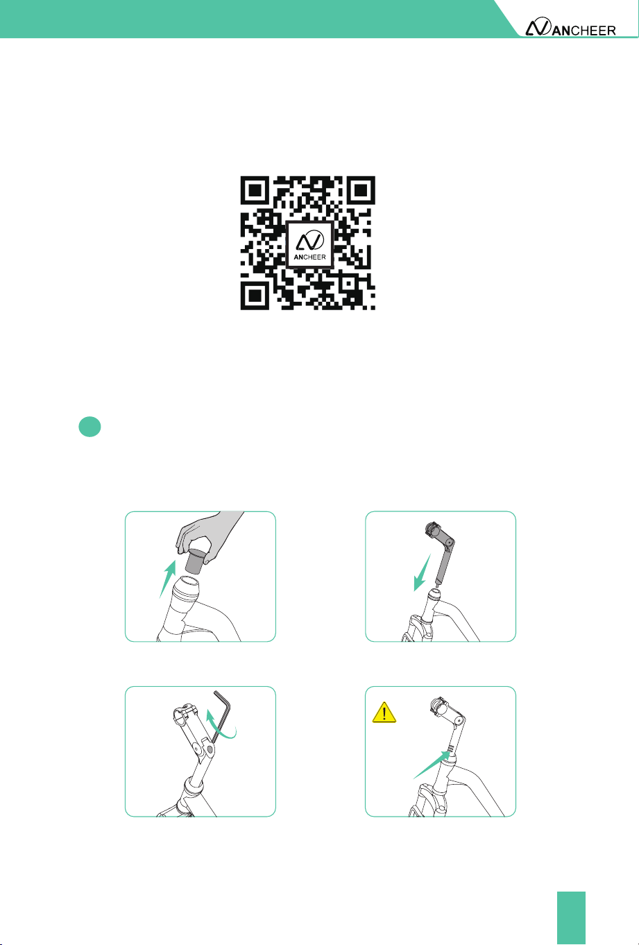
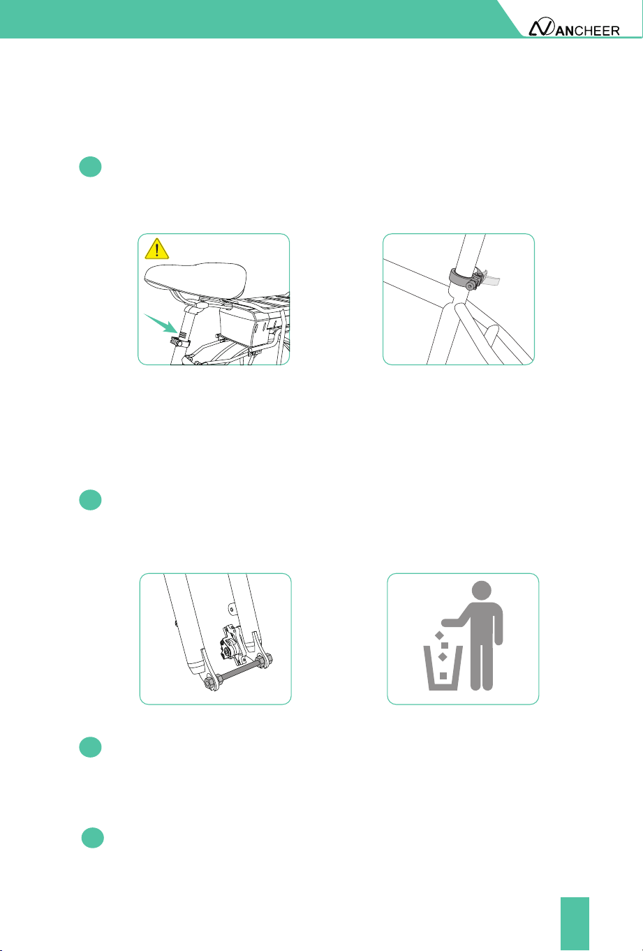
1. Install The Handlebar
Remove the protective plug, install the handlebar into the stem, align it
with the front fork, and then tighten the screw. Please be careful not to
exceed the limit line.
1.1
Don't exceed
the safety line.
10
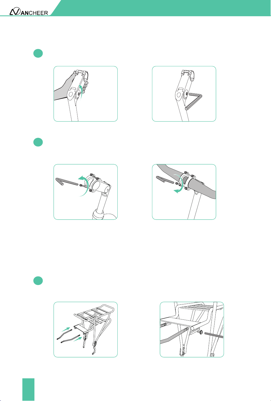
INSTALLATION AND ADJUSTMENT
Adjust the angle of the handlebar, and then tighten the screw.
Using the wrench from tool kit to further adjust the handlebar in a
property angel and position.
1.2
1.3
2. Install the Rack
Loosen the screws that secures the rack, put the rack in its position.
Then re-tighten the screws.
2.1
11
INSTALLATION AND ADJUSTMENT
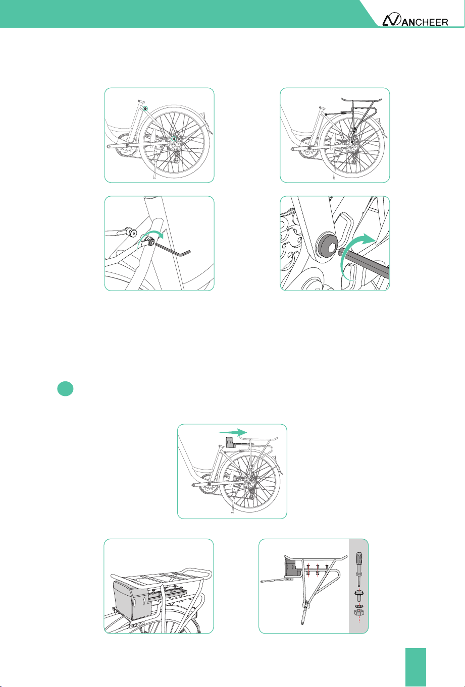
3. Install The Controller And Battery
Loosen the screws used to x the controller on the rear rack, then place
the controller on the front of the rear rack, re-x the screws and tighten
them.
3.1
12
OPEN
LOCK
INSTALLATION AND ADJUSTMENT
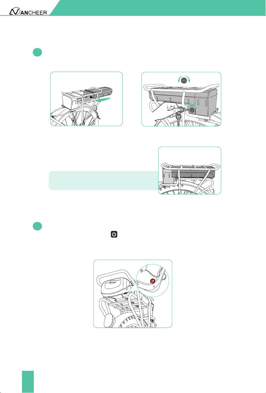
Push the battery along the slide, connect it with the controller tightly
and lock it .
After completing the installation, you can turn on the switch on the
battery, and press the " " button on the meter to see if the indicator
lights of the meter is on to conrm whether the controller and the
battery are properly connected.
3.2
3.3
The controller and battery should be
connected tightly.
Note:
13
INSTALLATION AND ADJUSTMENT
Using the tool to loosen the xing rod of the front fork and remove it
(this accessory is to prevent the front fork from being deformed during
delivery).
Install the saddle tube into post receiver. Set right its position and adjust
height to t your ridding habit. Please be careful not to exceed the limit
line. Then tighten the clamp that secures the saddle tube and fasten it.
5.1
4.1
4. Install the saddle tube
5. Install the front wheel
Don't exceed the safety
line.
5.2
Slide the wheel into the fork dropout slots. Insert the disc rotor into the
center of the disc brake at the same time you are inserting the wheel
axle into the fork drop out. Figure 4.3
5.3
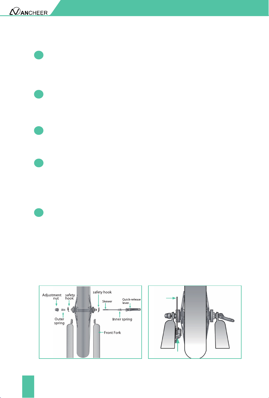
Unscrew the adjustment nut from the skewer, remove outer spring and
safety hook then slide the skewer through the front wheel axle so the
quick-release lever is on the same side of the chain. Figure 4.3
14
Disc
rotor
Caliper
5.7
5.8
Move the quick-release lever into the open position. With one hand on
the quick release lever and one hand on the adjustment nut, start to
hand tighten the adjustment nut until you start to feel some resistance
against the fork. Figure 4.4
Try to close the quick-release lever. If it closes easily, open it up and
tighten the adjustment nut further. If it is too dicult to close, open the
quick-release lever up and loosen the adjustment nut a little and try
again. Figure 4.4
NOTE: Do not attempt to tighten by turning the quick-release lever. The
quick-release lever is for closing, the adjustment nut is for adjusting the
tension.
Figure 4.3
INSTALLATION AND ADJUSTMENT
5.6
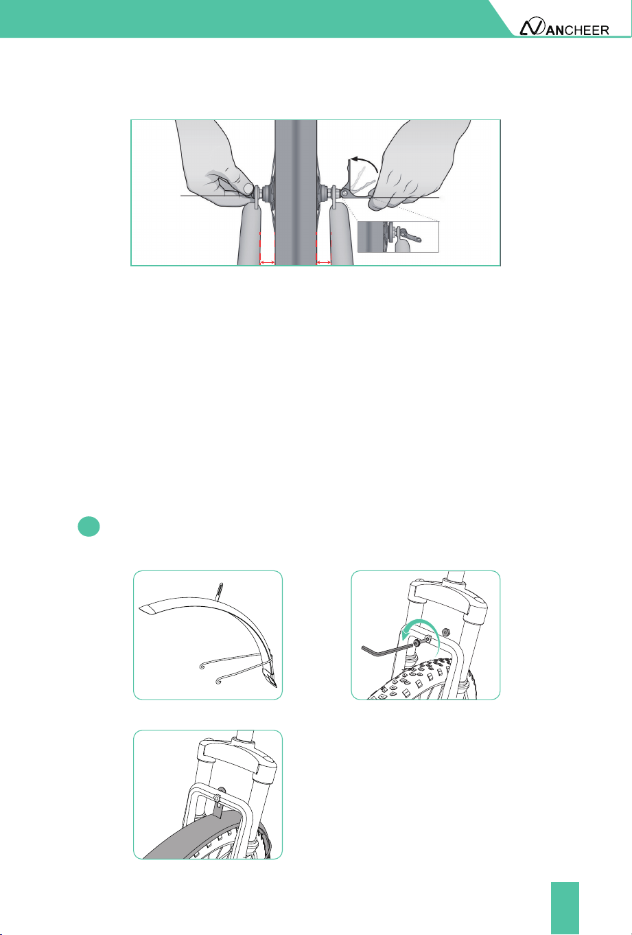
Re-check that the handlebars are perpendicular to the front wheel.
Adjust if needed. So you can adjust the distance A=distance B. Figure 4.4
5.5
5.4
Thread the adjustment nut back onto the skewer, but do not tighten too
far. Figure 4.3
Slide the outer spring and safety hook over the end of the skewer. Figure 4.3
Note: The smaller end of the spring should be in towards the wheel.
15
INSTALLATION AND ADJUSTMENT
NOTE: Make sure the wheel is in the middle of the fork. Length A= lenght B
Quick release
Attention:
Tighten the quick release
with the adjustment nut
only!
lever in the
closed position
Quick release
lever in the open
position
A
A = B
B
Figure 4.4
Important! You should feel resistance when you close the quick-release
lever that should leave a temporary impression on your ngers. Open
and close the handle to ensure the wheel is securely locked in place.
6. Assemble the front fender and headlight
Loosen the screw on the corresponding position of the front wheel, as
shown in the gure below. Put the fender in this position.
6.1
16
INSTALLATION AND ADJUSTMENT
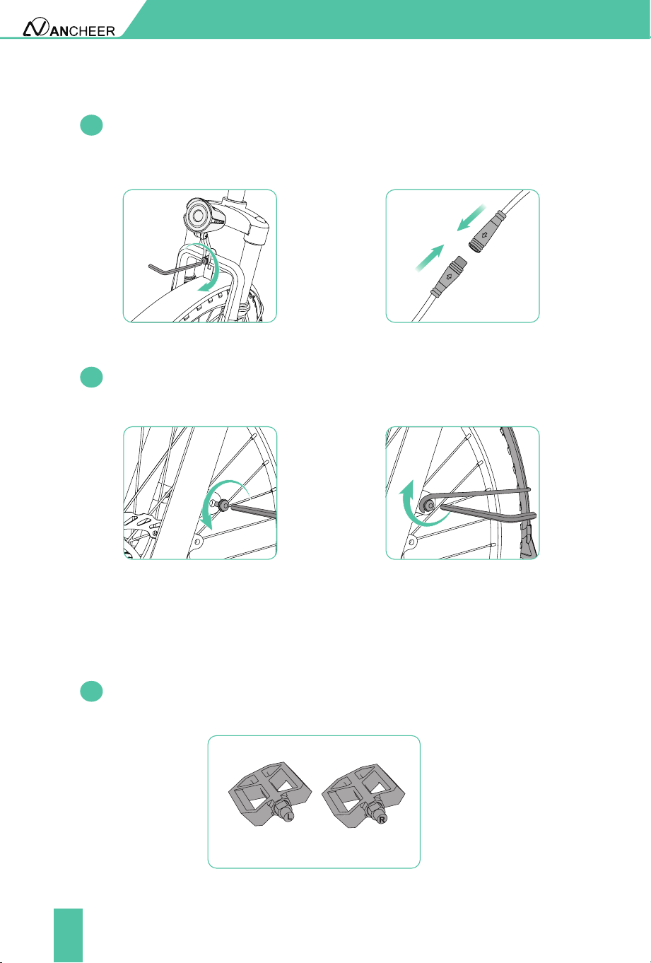
Loosen the screw on the fork with the hex key. Put the light in this
position. Tighten the screw that secures the light. Then connect the
plug when the arrow on the plug surface is aligned with the arrow.
Loosen the screws that secure the fender, x the fender and then tighten
them again.
There are a right pedal marked "R" and a left pedal marked "L". When
installing, make sure to identify the R/L letter on the pedal bolt.
6.2
6.3
7.1
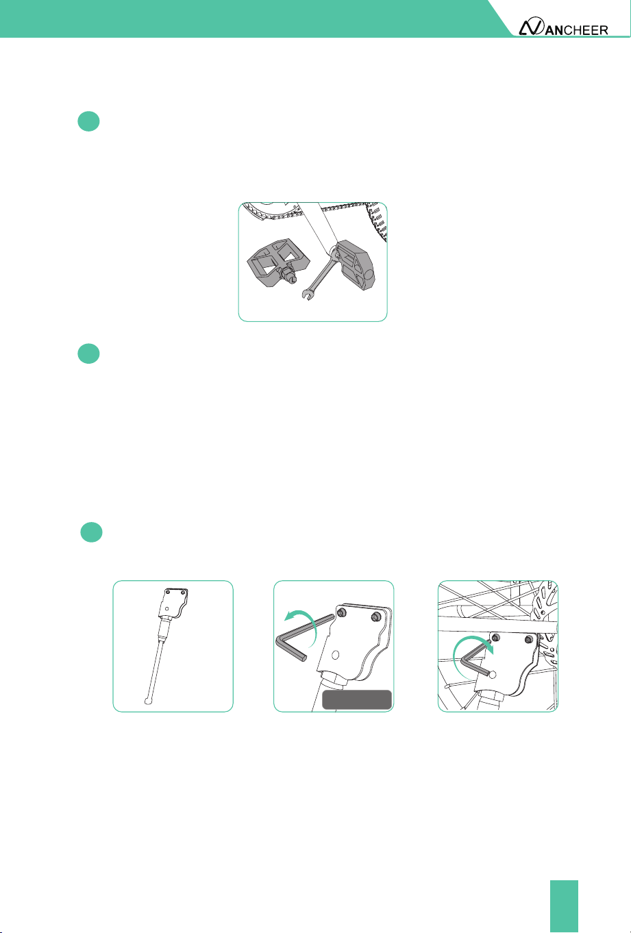
7. Install the pedals and the kickstand
17
INSTALLATION AND ADJUSTMENT
Finally, nd the corresponding position of the kickstand, install
the kickstand and x it with bolts.So far, congratulations! You have
completed the assembly of the entire bike.
Ensure that the thread of each pedal is fully inserted into the crank arm.
Tighten the pedals completely with a wrench. (Counterclockwise screw
the pedal marked "L" on the left side crank. Clockwise screw the pedal
marked "R" on the right side crank.)
7.3
7.2
8.1
Unscrew the screw in the kickstand, Install it and tighten the screw with
tool.
8. Install the kickstand
0.20 inch (5mm)
Allen Key
Tool:
18
METER OPERATION
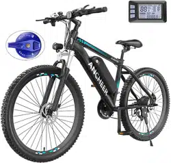
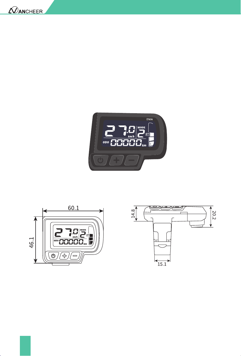
1. Product Name
2. Appearance And Dimensions
Intelligent LCD display for e-bike.
Fig. 2-2
Top View of Display
Dimensions
Fig. 2-3
Side View of Display
Dimensions
Fig. 2-1 Picture of Display

19
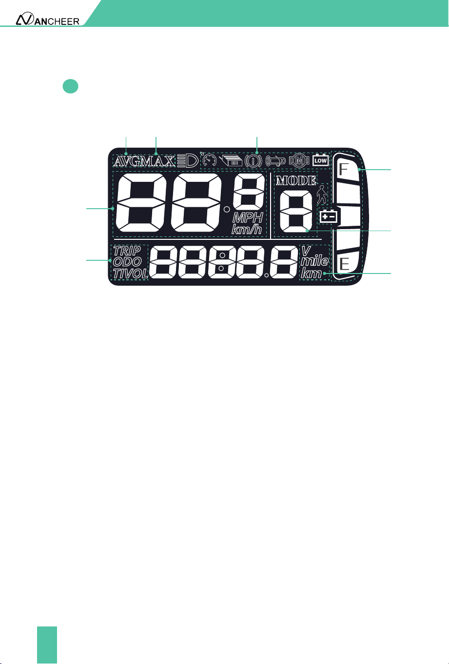
Display provides a variety of functions to meet the riding needs of users,
including:
3. Meter Function
3.2
Function Overview
Battery level indicator
Assist level adjustment and indication
Headlight indicator
Speed indicator (including real-time speed, maximum speed (MAXS)
and average speed (AVG))
Mileage indicator (including total mileage(ODO) and trip distance
(Trip))
Parameter setting function
●
●
●
●
●
●
METER OPERATION
There are three buttons on the operating unit of display, the on/o
button , plus button and minus button .
3.1
Button Denitions
20
3.3
Functional Area Layout
METER OPERATION
1 3
4
5
6
2
1:Average speed indicator
4:Battery level indicator
7:Trip distance indicator; ODO
6:Distance/speed unit — Metric system: km, km/h;Imperial system: mile, mph
3:Ebike Status Display Area
5:Pedal Assist Levels
8:Speed indicator — Speed unit Metric system: km/h; Imperial system: MPH
2:Maximum speed
8
7
21
METER OPERATION
By pressing and holding the button , the display will start to work
and the working power supply of the controller will be turned on. In the
power-on state, by pressing and holding the button , your e-bike will
be powered o.
If your e-bike is not used for more than 10 minutes, the display will
be automatically powered o.
4. General Operation
4.1
Power on/o
●
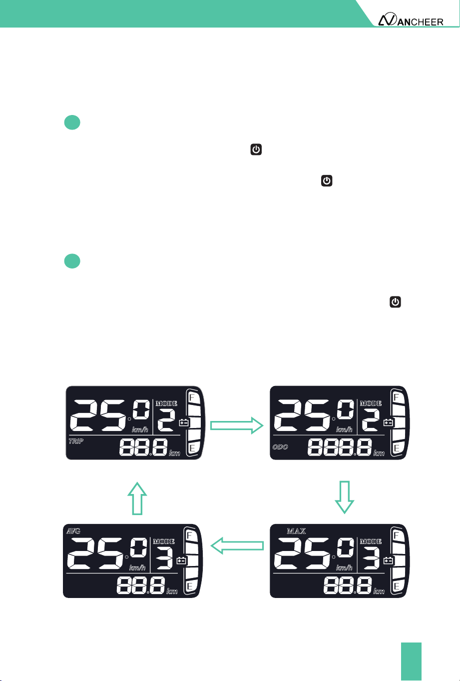
After the display is turned on, the display will show the real-time speed
(mph) and the mileage (mile) by default. By pressing the button ,
the information displayed will be switched between the mileage (mile),
ODO (mile), maximum speed (mph) and average speed (mph).
When the mileage reaches 9999.9 km, it will be automatically reset to zero.
4.2
Display interface
Mileage indicator
Average speed indicator
ODO
Maximum speed indicator
Fig. 4-1 Display Interface Switching
22
METER OPERATION
Full battery level
indication
Undervoltage
ashing
4.3
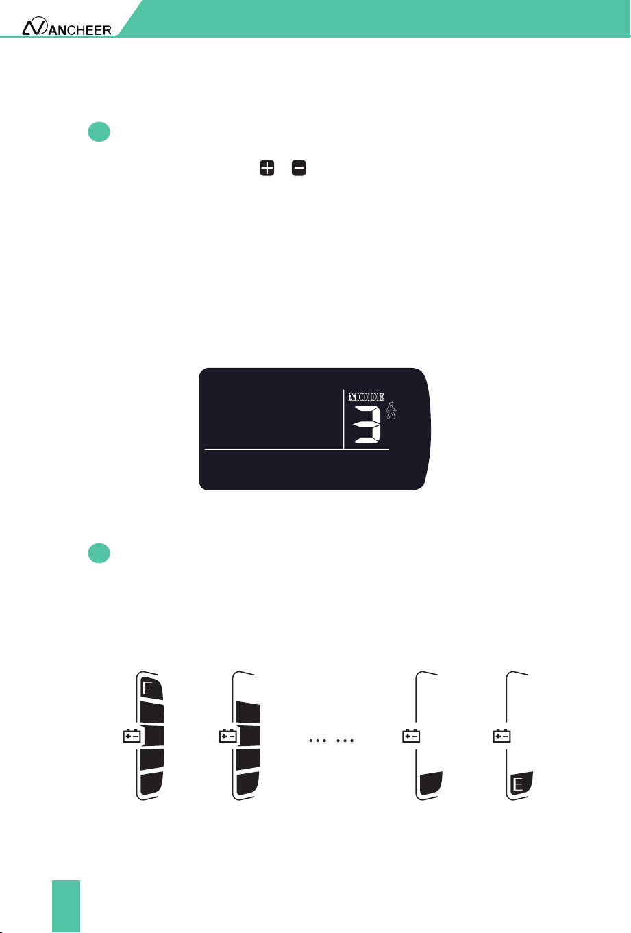
Assist level selection
By pressing the button / , the e-bike assist level will be switched
to change the motor output power. The assist levels available are levels
0-5. Level 0 is pure electric mode (throttle mode). PAS 1-5 are power-
assisted mode, and the default mode is level 1.
Cruise mode: When twisting and hold the throttle for 8 seconds, the
gear signal ashes, it will enter the auto cruise state, then release
the speed accelerator at this time, the electric bicycle will keep the
current speed and continue to drive. After braking or twist the throttle
again, you can cancel the cruise state. Please pay attention to the road
conditions and use cruiser mode carefully.
Fig. 4-4 Assist Level Switching Interface
Fig. 4-4 Battery level Switching Interface
4.4
Battery level indicator
The battery level indicator consists of ve segments. When the battery
is fully charged, the ve segments will be all on. In case of undervoltage,
the outline of the battery indicator will ash, which means the battery
has to be charged immediately.
23
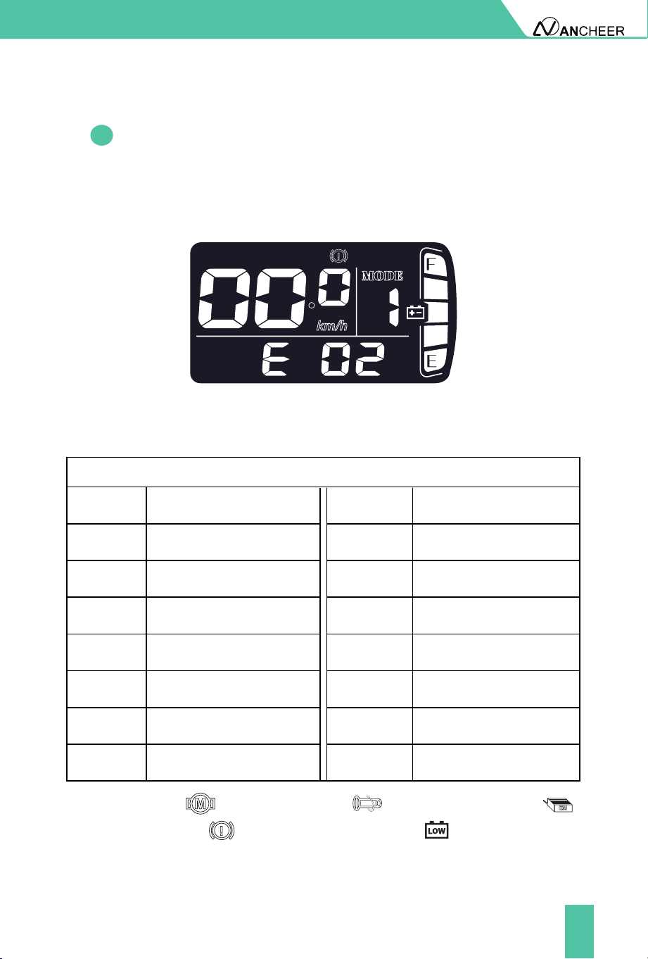
Motor Abnormalit: , Throttle Abnormality: , Controller Abnormality: ,
Brake Abnormality: , Undervoltage Protection:
METER OPERATION
4.5
Error code indicator
When a fault occurs in the electronic control system of your e-bike, the
display will automaticlly indicate the error code in the mileage area
in the format of E0*. Detailed denitions of error codes are shown in
Schedule 1.
Fig. 4-6 Error Code Indicator Interface
Schedule1 Error Code Denitions
Error codes
Error codes Error codes Denition Denition
Normal Status Motor Abnormality
Headlight Abnormality
Reserved Throttle Abnormality
Brake Abnormality
Assist Sensor Abnormality
6KM/H Cruise
Real-time Cruise
Battery Undervoltage
Controller Abnormality
Communication
Reception Abnormality
Communication
Transmission Abnormality
BMS Communication
Abnormality
E00 E07
E03 E10
E04 E11
E05 E12
E06 E13
E01 E08
E02 E09
When an error code appears on the display, please conduct
troubleshooting in time. Otherwise, your e-bike will not work normally.
■
24
METER OPERATION
5. General Setting
All parameters can only be set when your e-bike stops. The steps for
general setting are as follows:
In the power-on state, when the display shows the speed of 0,
■
6. Custom Setting
All parameters can only be set when your e-bike stops. The steps for
custom setting are as follows:
In the power-on state, when the display shows the speed of 0,
Press and hold the buttons and at the same time for more than
2 seconds to enter the selection interface of custom setting options;
Press the button / to switch the selection interface of general
setting options, and press the button to enter the parameter
modication interface;
Press the button / for parameter selection;
Press the button to save the parameter and return to the selection
interface of custom setting options;
Press and hold the button to save the parameter and exit the
selection interface of custom setting options.
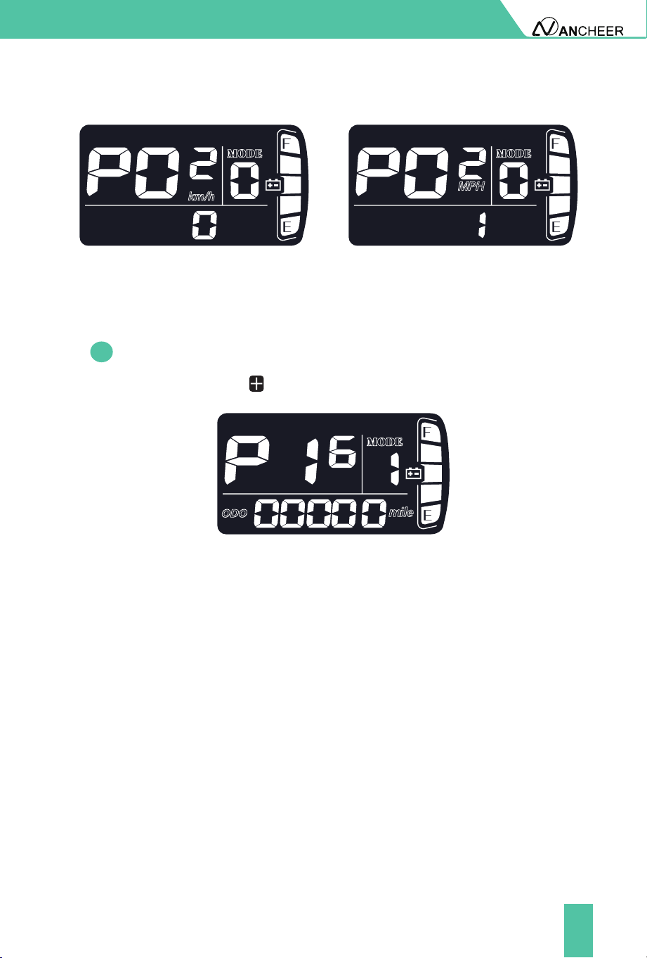
P02 refers to the metric/imperial system setting option. 0 represents
the metric system, and 1 represents the imperial system. Press the
button to enter the parameter modication interface. Press the
button / for parameter selection. Press the button to save the
parameter and return to the selection interface of general setting options.
6.1
Metric/imperial system setting
■
1
2
3
4
5
25
METER OPERATION
6.2
Odometer reset
Press and hold the " " buttons for more than 5 seconds to reset the
mileage.
Metric system indicator interface Imperial system indicator interface
Fig. 6-1 Metric/imperial System Setting Interface
Please use safely, and do not plug or unplug the display when it is powered on.
Please avoid bumping as far as possible.
Please do not alter the background parameter settings of the display at
will, otherwise normal riding cannot be guaranteed.
If the display fails to work normally, it should be repaired as soon as
possible.
Due to product upgrades of the Company, part of the displayed contents
or functions of the product you bought may be dierent from the manual,
depending on the actual model.
7. CAUTIONS
●
●
●
●

26
BATTERY AND CHARGING
Battery: Further information
Keep the battery out of reach of children.
Charging at 0°C~40°C/ 32°F~104°F, and discharging at -5°C~40°C/
23°F~104°F. Please do not store the battery in temperatures above 35°C/
95°F or below -5°C/ 23°F.
Keep the battery dry, do not put the battery in acidic or alkaline liquid,
keep away from rain, re and high temperature environment.
It is strictly forbidden to connect the positive and negative poles of the
battery reversely, and it is strictly forbidden to damage, disassemble or
short-circuit the battery.
Used batteries are hazardous chemicals, and the used batteries should
not be disassembled without authorization, and recycled by relevant
professional departments.
It is forbidden to modify the battery, electronic control system and the
frame structure of the bike, etc. Otherwise, it may cause safety hazards
and void the warranty service. If you continue to do so, all will be at your
own peril.
Use the original battery. Do not replace it with other brand's or product's
battery.
●
●
●
●
●
●
●
Please follow the instructions for use, otherwise the consequences are at
his own risk. Please use the original special charger. It is strictly prohibited
to use other chargers.
Pay attention to the battery type and applicable voltage that the charger
can charge, and it is strictly forbidden to mix them. The charging time
shall not exceed 12 hours, and the charging current shall not exceed 2A.
●
●
Charging: Safe operation guide
27
BATTERY AND CHARGING
When charging, it should be placed in a ventilated environment, and it is
strictly forbidden to charge in a conned space, residential building or in
a hot environment.
The charger should not be carried with the ebike as much as possible. If it
is really necessary to carry it, it should be placed in the toolbox after the
shock absorption treatment is done. It is not allowed to disassemble or
replace the components in the charger by yourself.
When not in use for a long time, keep the battery in a cool and dry place,
and charge the battery for two hours a month.
WHEN CHARGING THE BATTERY
●
●
●
●
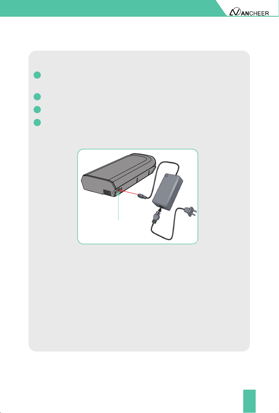
Insert the charger probe into the charger port on the e-bike battery. As
shown in the gure.
Insert the pronged end of the battery cord into the battery charger.
Insert the AC plug into an AC outlet.
The red indicator light turns on and will remain red until it is fully
charged. The indicator light turns green once the battery is fully
charged.
1
2
3
4
Charging port
28
BATTERY AND CHARGING
Battery: Further information
Reminder
Charge a new battery 4-6 hours before you use it in your product for the rst
time.
If the battery is dropped or damaged due to a bicycle accident, there may
be a danger of electrolyte leakage. Please stop using it immediately.
It is better not to wait until the power is completely exhausted before
charging, which can more eectively extend the battery life. Besides,
Overheating or undercharging the battery may shorten battery life.
How far can a fully charged battery go?
It depends on the load weight, road conditions and battery capacity.
But under the same conditions, the average speed can last longer riding
distances. Using pedal assist mode allows you to go further.
It is recommended to charge the battery in the reproof battery
charging cover when charging. And the battery should be stored in
the reproof battery charging cover when not in use.
Battery must be recycled or disposed of in an environmentally sound
manner.
Do not dispose of the battery in a re. The battery may explode or leak.
Do not dispose of a battery in your regular household trash.
Battery Disposal
●
●
●

29
MAINTENANCE
●
●
●
●
●
●
●
●
●
●
●
The front and rear wheels of the vehicle should be located in the center
of the front fork or frame.
After riding, please store the bike in a place without sunlight and rain.
Water showering is forbidden, and the surface of the car body can be
wiped with a semi-dry cloth.
Do not touch the charging hole on the bicycle, or touch it with metal,
otherwise, it may cause an accident due to an instantaneous short circuit
of the current.
Check all cables and cable housings for fraying, breaks, rust, or corrosion
and replace if necessary.
Check the motor and brake frequently, and do not ll the brake area with
oil. Additionally, check the brake pads for any damage as they will be
worn over time and eventually need replacement.
Regularly check the various screws of the car and the places that need to
be fastened, and regularly reinforce to prevent injury and unnecessary
wear and tear on your e-bike.
Recommended torque (unit: kgf.cm): the horizontal screw 60-80, the
stem screw 175- 200, the seat cushion screw 175-250, the wheel screw
320-450.
Regularly check the tension of the chain, which can be adjusted by the
chain regulator.
Always check the tire for scratches, cracks, or excessive wear. The inner
tube and the valve should be perpendicular to the wheel hub and not
crooked. Accidentally punctured, damaged or excessively worn inner and
outer tires need to be replaced immediately, please seek professional
technicians to repair or replace your tires.
It is forbidden to modify key structural parts such as the frame, front fork,
standpipe, and electrical function parts. If damaged, use the original parts
to replace it. Otherwise, the guarantee service will not be provided. Any
loss or damage caused by the modication shall be solely responsible.

30
Your electric bike includes a One Year Limited Hardware Warranty. ANCHEER
provides warranty service for the electric bikes. If there is a hardware defect
and a valid claim is received during the warranty period, we will resend new
parts within the scope permitted by law.
The Warranty covers product defects in materials and workmanship under
normal use. This Warranty is limited to original purchasers and is not
assignable or transferable.
The Warranty starts on the date of your purchase and lasts for one year (the
"Warranty Period") and the Warranty Period is not extended if the product
is repaired or replaced.
The Warranty does not cover any damage due to: improper use; failure to
follow the product instructions or to perform any preventive maintenance;
unauthorized repair; external causes such as accidents, abuse, or other
actions or events beyond our reasonable control.
Accessories Warranty Period Service ContentQuality Problem
A year
A year
A year
A year
A year
Motor
Controller
Charger
Lithium
Battery
Throttle
Free delivery of
parts
Free delivery of
parts
Free delivery of
parts
Free delivery of
parts
Free delivery of
parts
Failure occurs under
normal use
Failure occurs under
normal use
Failure occurs under
normal use
Failure occurs under
normal use
Failure occurs under
normal use
One-Year Limited Hardware Warranty
WARRANTY
Customer Services
We provide lifetime customer support services. For any questions about
the product, please contact customer service from where you brought the
equipment. We will be happy to answer your questions.
You can also email us your inquiries at support@iancheer.com.

31
Technical parameters
ATTACHMENT
Performance index Project Parameter
Wheel Size
Vehicle Size
26*1.95 Inches
Frame Material Aluminium Alloy
Maximum Load 120KG
Vehicle Weight 27.6KG
Maximum Speed 20mph(32km/h)
Recommended Gradient <= 15 degrees
Rear Derailleur 7-Speed
Working Temperature 23°F-104°F (-5℃~40℃)
Rated Voltage 48V
Battery Capacity 10.4ah
Service Life 500 Times
Charging time 3-4hours
Motor Power 350W
Motor Type Brushless Gear Motor
Maximum Torque 50N.M
Input Voltage AC100-240V
Input Current 3A
Output Voltage DC54.6V
1850*660*1060 MM
Basic
Parameters
Performance
Parameters
Battery
Parameters
Motor
Parameters
Charger
Parameters

32
ATTACHMENT
Display
Suspension
Digital Display
Suspension Front Fork
Brake
Light
Disc Brake
Front light and rear Light
Remarks:
After fully charged, the charger indicator light turns from red to green.
The amount of battery remaining, load of the bike(weight of rider and
cargo), tire pressure, road environment, chain and wheel axle lubrication,
etc. will aect the maximum speed;
Riding habits, temperature, load, tire pressure, road environment and
other factors will aect the riding range.
●
●
●
Performance index Project Parameter
Other
Parameters

33
WARNING
Operation General
Personal Restrictions
Only use the e-bike and the drive assist system for safe, recreational riding.
Use of the e-bike for a purpose it was not intended for is dangerous and
could result in property damage, serious injury or death. Always follow the
instructions for intended use and limitations.
Use of this e-bike by persons (including children) with reduced physical,
sensory or mental capabilities or persons lacking experience and
knowledge in the use of the e-bike could result in serious injury or death.
The owner of this e-bike must ensure this product is not used by people
with the conditions described above. Always follow the rules, regulations
and laws (including age limits) related to the use of an e-bike in its area
of use.
A child may not realize or understand the e-bike has moving parts and
components (e.g. battery). Never allow children to play or come into
contact with the e-bike or its parts. Always follow all rules, regulations
and laws regarding age limits and operation in the e-bike area of use.
Riding the e-bike through water could result in loss of control and damage
to the drive assist system. Do not ride into, or attempt to ride through,
water or sub-merge any part of the e-bike.
Riding with the kickstand in the down position may result in unexpected
contact with the ground or other objects causing loss of control. Always
ensure the kickstand is in the up position and securely locked in place
before riding the e-bike.
Sitting on the e-bike with the kickstand down may result in the e-bike
tipping over. Never sit on the e-bike when it is only supported and
stabilized by the kickstand. The kickstand is not designed to support the
weight of a person.
Overloading a rear basket could create dangerous riding conditions. Always
observe the maximum weight limit. Never overload the rear basket.
An improperly secured load on a rear rack could create dangerous riding
conditions. Always ensure the load on the rear rack is properly secured
before riding.
●
●
●
●
●
●
●
●

34
Never move the shifter while pedaling backward, nor pedal backwards
immediately after having moved the shifter. This could jam the chain and
cause serious damage to the bicycle.
Like any mechanical device, a bicycle and its components are subject to
wear and stress. Dierent materials and mechanisms wear or fatigue from
stress at dierent rates and have dierent life cycles. If a component’s
life cycle is exceeded, the component can suddenly and catastrophically
fail, causing serious injury or death to the rider.
Scratches, cracks, fraying and discoloration are signs of stress caused
fatigue and indicate that a part is at the end of its useful life and needs to
be replaced. Product life is often related to the kind of riding you do and
to the treatment to which you submit the bicycle. The bicycle’s warranty
is not meant to suggest that the bicycle cannot be broken or will last
forever. It only means that the bicycle is covered subject to the terms of
the warranty.
Frequent inspection of your bike is important to your safety. Periodic,
more detailed inspection of your bicycle is important. How often this
more detailed inspection is needed depends upon you.You, the rider/
owner, have control and knowledge of how often you use your bike,
how hard you use it and where you use it. The materials used to make
your bike determine how and how frequently to inspect. Ignoring this
WARNING can lead to frame, fork or other component failure, which can
result in serious injury or death.
●
●
●
●
Operation Details:
Correct tightening force on fasteners- nuts, bolts, screws- on your bicycle
is important. Too little force, and the fastener may not hold securely. Too
much force, and the fastener can strip threads, stretch, deform or break.
Either way, incorrect tightening force can result in component failure,
which can cause you to loose control and fall.
Loose or damaged handlebar grips or extensions can cause you to lose
control and fall. Unplugged handlebars or extensions can cut you and
cause serious injury in an otherwise minor accident.
●
●

35
Operation Details:
The area in which you ride may require specic safety devices. It is your
responsibility to familiarize yourself with the laws of the area where you
ride and to comply with all applicable laws, including properly equipping
yourself and your bike as the law requires. Observe all local bicycle laws
and regulations. Observe regulations about bicycle lighting, licensing
of bicycles, riding on sidewalks, laws regulating bike path and trail use,
helmet laws, child carrier laws, special bicycle trac laws. It’s your
responsibility to know and obey the laws. Failure to wear a helmet when
riding may result in serious injury or even death.
Do not remove the front or rear reectors or reector brackets from your
bicycle. They are an integral part of the bicycle’s safety system. Removing
the reectors reduces your visibility to others using the roadway.Being
struck by other vehicles may result in serious injury or death.The reector
brackets may protect you from a brake straddle cable catching on the tire
in the event of brake cable failure. If a brake straddle cable catches on the
tire, it can cause the wheel to stop suddenly, causing you to lose control
and fall.
Although many catalogs, advertisements and articles about bicycling
depict riders engaged in extreme riding, this activity is extremely
dangerous, increases your risk of injury or death, and increases the severity
of any injury. Remember that the action depicted is being performed by
professionals with many years of training and experience. Know your
limits and always wear a helmet and other appropriate safety gear.
Even with state- of the-art protective safety gear, you could be seriously
injured or killed when jumping, stunt riding, riding downhill at speed or
in competition.Bicycles and bicycle parts have limitations with regard to
strength and integrity, and this type of riding can exceed those limitations
or dramatically reduce the length of their safe use.
Failure to conrm compatibility, properly install, operate and maintain
any component or accessory can result in serious injury or death.Exposed
springs on the saddle of any bicycle tted with a child seat can cause
serious injury to the child.Changing the components on your bike with
other than genuine replacement parts may compromise the safety of
your bicycle and may void the warranty. Contact customer service before
changing the components on your bike.
●
●
●
●

36
If your seat post is not inserted in the seat tube, the seat post, binder or
even frame may break, which could cause you to lose control and fall.
When making saddle angle adjustments with a single bolt saddle clamp,
always check to make sure that the serrations on the mating surfaces of the
clamp are not worn. Worn serrations on the clamp can allow the saddle to
move, causing you to lose control and fall. Always tighten fasteners to the
correct torque. Bolts that are too tight can stretch and deform. Bolts that
are too loose can move and fatigue. Either mistake can lead to a sudden
failure of the bolt, causing you to lose control and fall.
An insuciently tightened stem clamp bolt, handlebar clamp bolt or bar
end extension clamping bolt may compromise steering action, which
could cause you to lose control and fall. Place the front wheel of the bicycle
between your legs and attempt to twist the handlebar/stem assembly. If
you can twist the stem in relation to the front wheel, turn the handlebars
in relation to the stem, or turn the bar end extensions in relation to the
handlebar, the bolts are insuciently tightened.Be aware that adding
aerodynamic extensions to handlebars will change the steering and
braking response of the bicycle.
Bolt or bar end extension clamping bolt may compromise steering action,
which could cause you to lose control and fall. Place the front wheel of
the bicycle between your legs and attempt to twist the handlebar/stem
assembly. If you can twist the stem in relation to the front wheel, turn
the handlebars in relation to the stem, or turn the bar end extensions in
relation to the handlebar, the bolts are insuciently tightened.Be aware
that adding aerodynamic extensions to handlebars will change the steering
and braking response of the bicycle.
WARNING! The shorter the brake lever reach, the more critical it is to have
correctly adjusted brakes, so that full braking power can be applied within
available brake lever travel. Brake lever travel insucient to apply full
braking power can result in loss of control, which may result in serious
injury or death.
All quick-release levers should be inspected before every ride to be sure
they are fully closed and secure. Failure to properly close a quick-release
lever can cause loss of control of the bicycle resulting in injury or death.
Make sure the wheel is properly seated and the quick-release lever is
properly closed.
Disregarding or misunderstanding of the following safety warnings, the
safety warnings in the manuals associated with the e-bike parts, and safety
labels on the e-bike could result in serious injury or death.
●
●
●
●
●
●

37
Anyone assembling, using, maintaining, transporting or storing this
e-bike must read, understand, and follow these safety warnings before
performing any of the actions stated.
SAVE THESE INSTRUCTIONS.
●

Customer Service
Input: 54.6V, 3A max
Highest speed: 20mph (32km/h)
Power: 350W
support@iancheer.com
KOMDA INDUSTRIAL(DONGGUAN)CO, LTD
Made in China
Model: AMA005929
E Bike