Download the app
& activate product
Warning notices: Before using this product, please read this manual carefully and keep it for future reference.
The design and specifications are subject to change without prior notice for product improvement.
Consult with the dealer or manufacturer for details.
The diagram above is just for reference. Please take the appearance of the actual product as the standard.
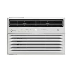
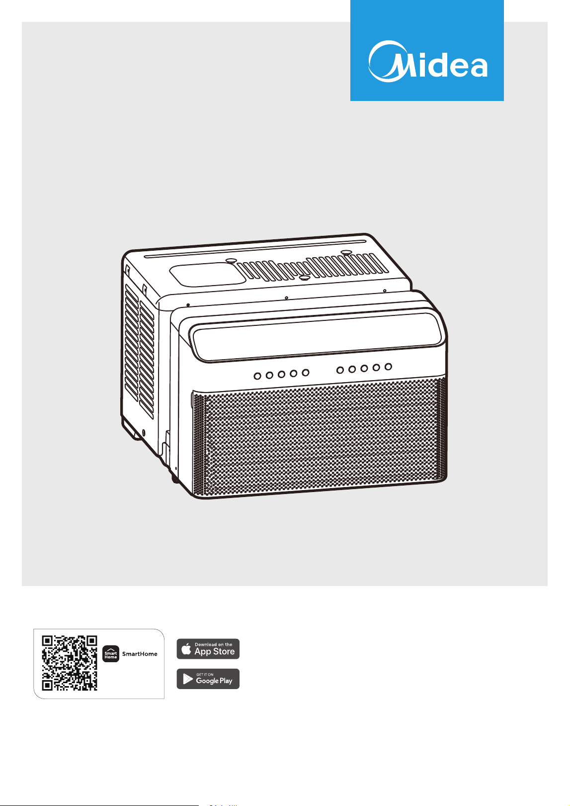
Window Air Conditioner
MAW
USER MANUAL
MAW08W1QWT
MAW10W1QWT
MAW12W1QWT
12
THANK YOU FOR CHOOSING MIDEA!
Before using your new Midea product, please review this manual thoroughly to ensure safe and eective
operation of its features and functions.
CONTENTS
REMOTE CONTROL AND SMART APP SETUP
2
18
23
41
42
46
44
45
A2L
Safety and Inspection Guidelines
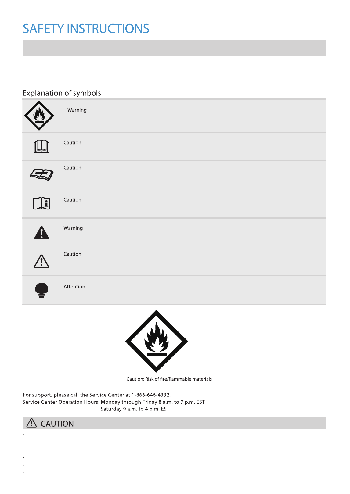
This symbol indicates that the operation manual should be read carefully.
This symbol indicates that a service personnel should be handling this equipment with reference to the installation
manual.
This symbol indicates operating and installation instructions.
This signal indicates a medium-level hazard that, if not avoided, could result in death or serious injury.
This signal indicates a hazard with a low degree of risk which, if not avoided, may result in a minor or moderate
injury.
This signal indicates important information (i.e. prevent property damage) but does not represent danger.
3
A2L
This symbol indicates that the unit uses a ammable refrigerant. If the refrigerant leaks and comes into contact
with an ignition source, there is a risk of re.
These guidelines are provided to prevent risks and damage from unsafe operation of the unit. Inspect the packaging and unit upon
arrival to ensure integrity. If any damage is found, contact the retailer or dealer immediately. Modications or alterations to the unit
are prohibited. Unintended use may result in hazards and void warranty claims.
This unit is not intended for use by people (including children) with reduced physical, sensory, or mental capabilities or lack of
experience and knowledge, unless they have been given supervision or instruction concerning use of the unit by a person
responsible for their safety.
Children should be supervised to ensure that they do not play with the unit.
The unit shall be installed in accordance with national wiring regulations.
Do not operate the air conditioner in a humid room such as a bathroom or laundry room.

WARNING
4
• Plug in power cord plug properly.
• Do not modify power cord length or share the outlet with other appliances.
•
Always ensure effective grounding.
• Ventilate room before operating the air conditioner if there is a gas leakage from another appliance.
• Do not operate or stop the unit by inserting or pulling out the power cord plug.
• Do not operate with wet hands or in very humid environments.
• Do not allow water to come into contact with any electric parts.
• Do not use the socket if it is loose or damaged.
• Do not use or keep the power cord close to heating appliances.
• Do not use any devices or materials for installation that are not recommended in this manual.
• Do not disassemble or modify unit.
• Do not damage or use an alternate power cord.
If the power cord is damaged, it must be replaced by the manufacturer or an authorized service center or a similarly
qualified person in order to avoid a hazard.
• Do not open the unit during operation.
•
Avoid directing the unit's airflow directly towards individuals to prevent potential health risks.
Do not use the power cord near flammable gas or combustibles. (i.e. gasoline, benzene, thinner etc)
•
•
Do not use an extension cord or an adapter plug or remove any prongs from the power cord.
• Ensure the unit is properly grounded using the three-prong plug to enhance electrical safety.
• Use the unit with a properly grounded wall receptacle. If the receptacle is not adequately grounded or protected by a
time-delay fuse or circuit breaker, have a qualified electrician install a suitable one. Ensure the receptacle remains
accessible after the unit is installed.
• Verify that the electrical service meets the requirements forthe specific model. Refer to the serial plate on the side of
the cabinet, behind the grille, for this information.
• Do not ingest water drained from the unit.
• Be sure the air conditioner has been securely and correctly installed according to the installation instructions in this manual.
Save this manual for future reference when removing or re-installing this unit.
• Unplug the unit if unusual sounds, smells or smoke are from it.
• Do not let children hang onto the air conditioner or bracket.
removing the air filter.
Turn off the unit and switch off the circuit breaker before cleaning.
If water spills on the unit, turn it off, switch off the circuit breaker, unplug the power supply and contact customer service.
Do not clean the unit with water.
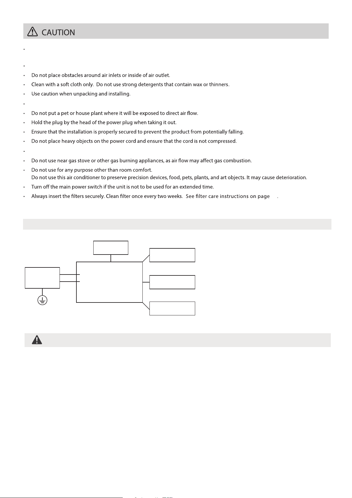
Electronic Work
WARNING:
BEFORE PERFORMING ANY ELECTRICAL OR WIRING WORK, TURN OFF THE
MAIN POWER TO THE SYSTEM.
Main Control
Compressor
Fan Motor
Display
Power
Supply
L/AC L/L1/L-IN
N/AC N/L2/N-IN
Other
41
Turn off the unit and switch off the circuit breaker before cleaning. Do not touch the metal parts of the unit when
NOTE:
Please strictly follow the
wiring label attached to the
machine for all wiring connections.
The wiring diagram may vary for
dierent unit. Please refer to the
wiring diagram on the machine.
The above wiring diagram is a
simplified version for preliminary
illustration purposes only.
5

• Servicing shall only be performed as recommended by the equipment manufacturer. Maintenance and
repair requiring the assistance of other skilled personnel shall be carried out under the supervision of a
person competent in the use of fl ammable refrigerants.
• DO NOT modify the length of the power cord or use an extension cord to power the unit.
• DO NOT share a single outlet with other electrical appliances. Improper power supply can cause fi re or
electrical shock.
•
WARNING
Flammable!
Refrigerant R32 is used within the unit.
• When maintaining or disposing the unit, the refrigerant (R32) shall be recovered properly, shall not
discharge to air directly.
• Compliance with national gas regulations shall be observed.
• Keep ventilation openings clear of obstruction.
•
• A warning that the unit shall be stored in a well-ventilated area where the room size corresponds to the
room area as specifi ed for operation.
WARNING
• Any person who is involved with working on or breaking into a refrigerant circuit should hold a current
valid certifi cate from an industry-accredited assessment authority, which authorizes their competence to
Examples for such working procedures are:
• Breaking into the refrigerating circuit;
• Opening of sealed components;
• Opening of ventilated enclosures.
•
fl ammable refrigerant, and follow instructions carefully to prevent mechanical damage.
• Do not use means to accelerate the defrosting process or to clean, other than those recommended by the
manufacturer.
• The unit shall be stored in a room without continuously operating ignition sources (i.e. open fl ames, an
operating gas appliance) and ignition sources (i.e. an operating electric heater) close to the unit.
• Do not pierce or burn.
• Be aware that the refrigerants may not contain an odor.
handle refrigerants safely in accordance with an industry recognized assessment specification. All training
shall follow the ANNEX HH requirements of UL 60335-2-40 4th Edition.
6
Please follow the instructions carefully to handle, install, clean and service the unit to avoid any damage
or hazard.
The unit shall be stored so as to prevent mechanical damage from occurring.
Keep the unit away from open flames or devices that may cause sparks to avoid igniting the

How To Handle Equipment Containing Flammable Refrigerants
1. Transport of equipment containing fl ammable refrigerants.
See transport regulations.
2. Marking of equipment using signs.
See local regulations.
3. Disposal of equipment using fl ammable refrigerants.
See national regulations.
6. Information on servicing.
1) Checks to the area
Prior to beginning work on systems containing fl ammable refrigerants, safety checks are necessary
to ensure that the risk of ignition is minimized. For repair to the refrigerating system, the following
precautions shall be complied with prior to conducting work on the system.
2) Work procedure
Work shall be undertaken under a controlled procedure so as to minimize the risk of a fl ammable gas or
vapor being present while the work is being performed.
3) General work area
All maintenance staff and others working in the local area shall be instructed on the nature of work being
carried out. Work in confi ned spaces shall be avoided. The area around the workspace shall be sectioned
4) Checking for presence of refrigerant
The area shall be checked with an appropriate refrigerating detector prior to and during work, to ensure the
technician is aware of potentially fl ammable atmospheres. Ensure that the leak detection equipment being
used is suitable for use with fl ammable refrigerants. (i.e. non-sparkling, adequately sealed or intrinsically safe).
5) Presence of fi re extinguisher
If any hot work is to be conducted on the refrigeration equipment or any associated parts, appropriate
fi re extinguishing equipment shall be available to hand. Have a dry powder or CO2 fi re extinguisher
adjacent to the charging area.
6) No ignition sources
During work on refrigeration systems involving pipes containing or having contained fl ammable
refrigerants, individuals must avoid using any ignition sources that could potentially cause fi re or
explosion risks. This includes maintaining a safe distance from the installation, repair, removal, and
disposal sites where fl ammable refrigerants may be present. Before commencing work, the surrounding
area must be inspected to ensure there are no fl ammable hazards or ignition risks. Additionally, ‘No
Smoking’ signs should be prominently displayed.
off. Ensure that the conditions within the area have been made safe by control of flammable material.
7) Ventilated area
Before initiating any system breach or conducting hot work, ensure the area is outdoors or properly
ventilated. Adequate ventilation must be maintained throughout the duration of the work to safely
disperse any released refrigerant, ideally venting it externally into the atmosphere.
The storage of the appliance should be in accordance with the applicable regulations or instructions,
whichever is more stringent.
7
4. Storage of equipment.
5. Storage of packed (unsold) unit.
Storage package protection should be constructed such that mechanical damage to the unit inside the
package will not cause a leak of the refrigerant charge. The maximum number of pieces of equipment
permitted to be stored together will be determined by local regulations.

8) Checks to the refrigerating equipment
When replacing electrical components, ensure they are suitable for their intended purpose and meet
the correct specifi cations. Always adhere to the manufacturer’s maintenance and service guidelines. If
uncertain, seek guidance from the manufacturer’s technical department. The following checks should be
performed for installations utilizing fl ammable refrigerants:
The refrigerant charge must align with the size of the room where refrigerant-containing parts are
installed. Ensure ventilation systems and outlets operate effectively and remain unobstructed. If using
an indirect refrigerating circuit, verify the presence of refrigerant in the secondary circuit. Equipment
markings must be visible and legible at all times; any illegible markings or signs should be promptly
corrected. Refrigeration pipes and components should be installed in locations unlikely to expose them
to corrosive substances, unless they are inherently corrosion-resistant materials or adequately protected
against corrosion.
9) Checks to electrical devices
Repair and maintenance of electrical components must begin with initial safety checks and thorough
inspection procedures. If a fault is identifi ed that could pose a safety risk, no electrical supply should be
connected to the circuit until the issue is resolved. If immediate correction of the fault isn't
feasible but operation must continue, a suitable temporary solution must be implemented. This action
Initial safety checks shall include:
Ensure capacitors are discharged safely to prevent sparking. Ensure no live electrical components or
exposed wiring during charging, recovering, or purging the system. Verify continuity of earth bonding
throughout these procedures.
7. Sealed electrical components shall be replaced.
8. Intrinsically safe components must be replaced.
9. Cabling.
Check that cabling will not be subject to wear, corrosion, excessive pressure, vibration, sharp edges or any
other adverse environmental effects. The check shall also take into account the effects of aging or continual
vibration from sources such as compressors or fans.
10. Detection of fl ammable refrigerants.
Under no circumstances should potential sources of ignition be used during the search for or detection
of refrigerant leaks. This includes avoiding the use of halide torches or any other detectors that utilize
naked fl ames.
The following leak detection methods are deemed acceptable for systems containing fl ammable
refrigerants. Electronic leak detectors shall be used to detect fl ammable refrigerants, but the sensitivity
may not be adequate, or may need re-calibration.
(Detection equipment shall be calibrated in a refrigerant-free area).
Ensure that the detector is not a potential source of ignition and is suitable for the refrigerant used. Leak
detection equipment shall be set at a percentage of the LFL of the refrigerant and shall be calibrated
to the refrigerant employed and the appropriate percentage of gas (25% maximum) is confi rmed. Leak
detection fl uids are suitable for use with most refrigerants but the use of detergents containing chlorine
shall be avoided as the chlorine may react with the refrigerant and corrode the copper pipe-work.
If a leak is suspected, all naked fl ames shall be removed/extinguished. If a refrigerant leak requiring brazing
is detected, all refrigerant must be recovered from the system, or isolated (using shut-off valves) in a part of
the system away from the leak. Removal of refrigerant shall be according to “Removal and evacuation”.
8
should be promptly reported to the unit owner to ensure all parties are informed.

11. Removal and evacuation.
When breaking into the refrigerant circuit to make repairs - or for any other purpose - conventional
procedures shall be used. However, for fl ammable refrigerants it is important that best practice be
followed, since fl ammability is a consideration. The following procedure shall be adhered to:
- Safely remove refrigerant following local and national regulations;
- Evacuate;
- Purge the circuit with inert gas (optional for A2L);
- Evacuate (optional for A2L);
- Continuously fl ush or purge with inert gas when using fl ame to open circuit; and
- Open the circuit.
The refrigerant charge must be recovered into appropriate recovery cylinders if venting is prohibited by
local and national codes. For appliances containing fl ammable refrigerants, the system should be purged
with non-fl ammable refrigerants that are oxygen-free. Under no circumstances should compressed air or
oxygen be used for purging refrigerant systems.
For appliances containing fl ammable refrigerants, purging must be conducted by initially breaking the
vacuum in the system with oxygen-free nitrogen. Nitrogen should be continuously added until the desired
working pressure is reached, then vented to the atmosphere. Subsequently, the system should be pulled
down to a vacuum (this step is optional for A2L refrigerants). This purging process should be repeated until
no refrigerant remains in the system (optional for A2L refrigerants). After the fi nal charge of oxygen-free
nitrogen is used, the system should be vented to atmospheric pressure to facilitate further work.
The outlet for the vacuum pump shall not be close to any potential ignition sources, and ventilation shall
be available.
The refrigerant charge shall be recovered into the correct recovery cylinders if venting is not allowed by
local and national codes. For appliances containing fl ammable refrigerants, the system shall be purged
with oxygen-free nitrogen to render the appliance safe for fl ammable refrigerants. This process might
need to be repeated several times. Compressed air or oxygen shall not be used for purging refrigerant
systems. For appliances containing fl ammable refrigerants, refrigerants purging shall be achieved by
breaking the vacuum in the system with oxygen-free nitrogen and continuing to fi ll until the working
pressure is achieved, then venting to atmosphere, and fi nally pulling down to a vacuum (optional for A2L).
This process shall be repeated until no refrigerant is within the system (optional for A2L). When the fi nal
oxygen-free nitrogen charge is used, the system shall be vented down to atmospheric pressure to enable
work to take place. Ensure that the outlet for the vacuum pump is not close to any potential ignition
sources and that ventilation is available.
12. Charging procedures.
In addition to conventional charging procedures, the following requirements shall be followed. Ensure that
contamination of different refrigerants does not occur when using charging equipment. Hoses or lines shall
be as short as possible to minimize the amount of refrigerant contained in them. Cylinders shall be kept
in an appropriate position according to the instructions. Ensure that the refrigeration system is earthed
prior to charging the system with refrigerant. Label the system when charging is complete (if not already).
Extreme care shall be taken not to overfi ll the refrigeration system. Prior to recharging the system it shall
be pressure tested with OFN. The system shall be leak tested on completion of charging but prior to
commissioning. A follow up leak test shall be carried out prior to leaving the site.
How To Handle Equipment Containing Flammable Refrigerants (cont.)
9

13. Decommissioning.
Before carrying out this procedure, it is essential that the technician is completely familiar with the
Before commencing the task, it is essential to take oil and refrigerant samples in case analysis is needed
before reclaimed refrigerant can be reused. Ensure electrical power is available prior to starting the task.
a. Become familiar with the equipment and its operation.
b. Isolate system electrically.
c. Before attempting the procedure ensure that mechanical handling equipment is available if required for
handling refrigerant cylinders;
All personal protective equipment is available and being used correctly; The recovery process is supervised
at all times by a competent person; Recovery equipment and cylinders conform to the appropriate standards.
d. If possible, pump down the refrigerant system.
e. If a vacuum is not possible, make a manifold so that refrigerant can be removed from various parts of
the system.
f. Make sure that cylinder is situated on the scales before recovery takes place.
g. Start the recovery machine and operate in accordance with instructions.
h. Do not overfi ll cylinders. (No more than 80% volume liquid charge).
i. Do not exceed the maximum working pressure of the cylinder, even temporarily.
j. When the cylinders have been fi lled correctly and the process completed, make sure that the cylinders and
the equipment are removed from site promptly and all isolation valves on the equipment are closed off.
k. Recovered refrigerant shall not be charged into another refrigeration system unless it has been cleaned
and checked.
14. Labeling.
Equipment shall be labeled stating that it has been de-commissioned and emptied of refrigerant. The label
shall be dated and signed.
15. Recovery.
When removing refrigerant from a system, either for servicing or decommissioning, it is recommended
good practice that all refrigerants are removed safely.
When transferring refrigerant into cylinders, ensure that only appropriate refrigerant recovery cylinders
are employed. Ensure that the correct number of cylinders for holding the total system charge is available.
All cylinders to be used are designated for the recovered refrigerant and labeled for that refrigerant (i.e.
special cylinders for the recovery of refrigerant). Cylinders shall be complete with pressure-relief valve and
associated shut-off valves in good working order. Empty recovery cylinders are evacuated and, if possible,
cooled before recovery occurs.
The recovered refrigerant shall be processed according to local legislation in the correct recovery cylinder,
and the relevant waste transfer note arranged. Do not mix refrigerants in recovery units and especially not
in cylinders.
If compressors or compressor oils are to be removed, ensure that they have been evacuated to an
acceptable level to make certain that fl ammable refrigerant does not remain within the lubricant. The
compressor body shall not be heated by an open fl ame or other ignition sources to accelerate this process.
When oil is drained from a system, it shall be carried out safely.
Non-duct connected appliances containing A2L refrigerants with the supply and return air openings in the
conditioned space may have the body of the appliance installed in open areas such as false ceilings not
being used as return air plenums, as long as the conditioned air does not directly communicate with the air
of the false ceiling.
10
Ensure that there are labels on the unit stating the unit contains flammable refrigerant.
The recovery unit shall be in good working order with a set of instructions concerning the unit that is at
hand and shall be suitable for the recovery of the flammable refrigerant. If in doubt, the manufacturer
should be consulted. In addition, a set of calibrated weighing scales shall be available and in good working
order. Hoses shall be complete with leak-free disconnect couplings and in good condition.
unit and all its detail. It is recommended good practice that all refrigerants are recovered safely.
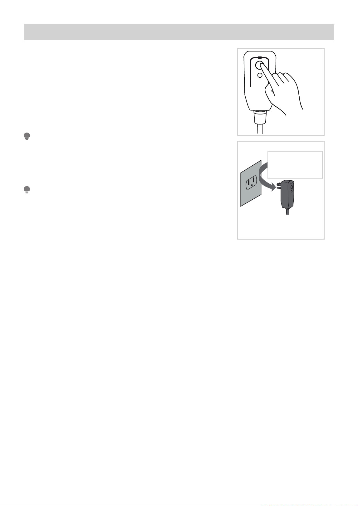
Operation of Current Device
RESE T
TEST
Plug in &
press RESET
The power supply cord with this air conditioner contains a current
detection device designed to reduce the risk of re.
In the event that the power supply cord is damaged, it can not be
repaired. It must be replaced with a cord from the manufacturer.
NOTE
• Do not use this device to turn the unit on or o.
• Always make sure the RESET button is pushed in for correct
operation.
•
NOTE
Do not, under any
circumstances, cut,
remove or bypass
the grounding prong.
Power supply cord with
3-prong grounding plug and
current detection device.
Grounding type wall receptacle
Do not, under any
circumstances, cut,
remove or bypass
the grounding prong.
If the power supply cord does not reset when the TEST button is pressed or
cannot be reset, it must be replaced. Please contact customer service for
assistance.
The power supply cord contains a current measuring device that detects
damage to the power cord. Test the power supply cord as follows:
1. Plug in the air conditioner.
2. The power supply cord will have TWO buttons on the plug head.
Press the TEST button. A click will be heard as the RESET button
pops out.
3. Press the RESET Button. A click will be heard as the button engages.
4. The power supply cord is now supplying electricity to the unit. (On
some units this is also indicated by a light on the plug head.)
11
PRODUCT INSTALLATION
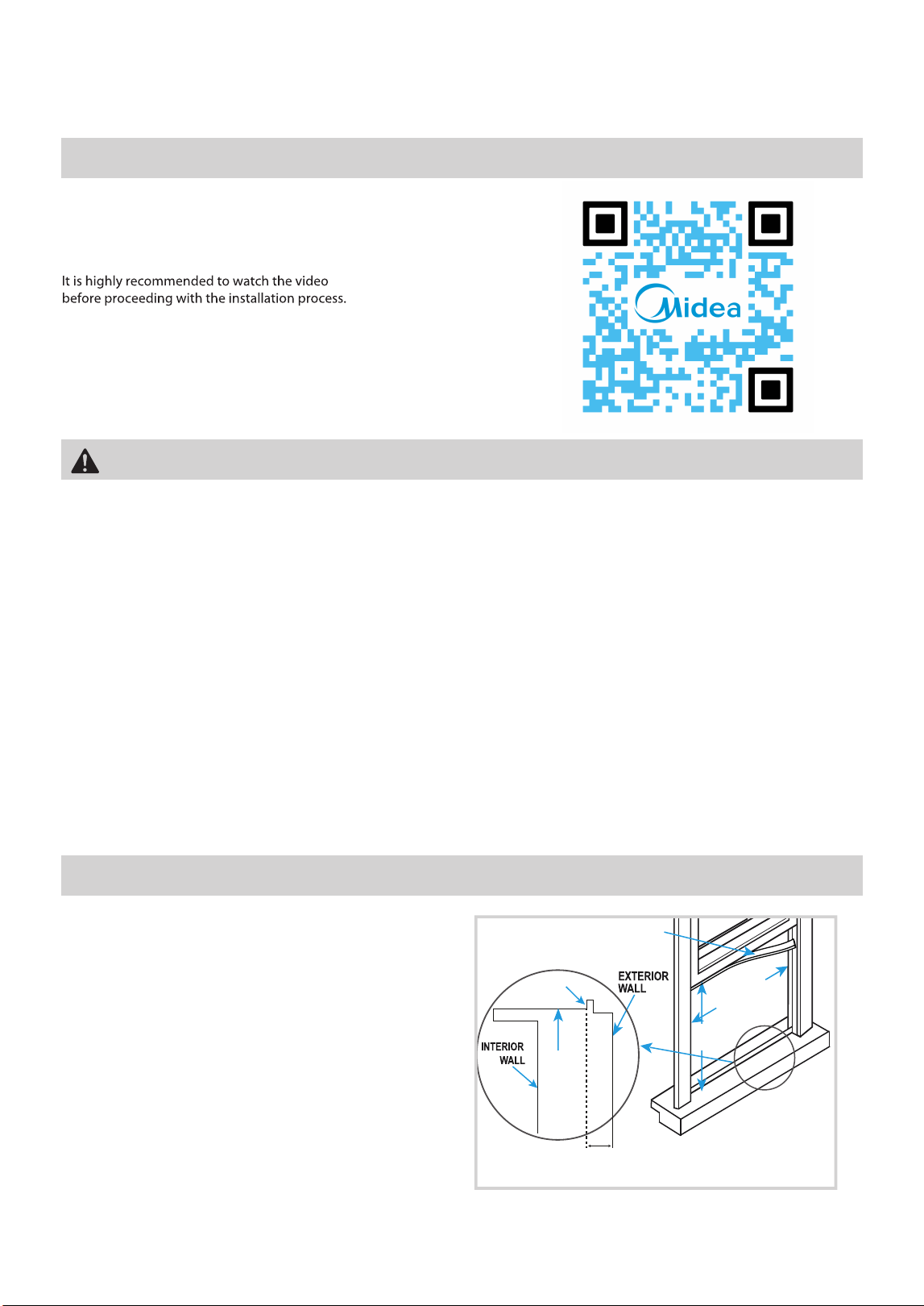
Installation Video
Window Requirements
Vinyl-Clad Windows
INNER
WINDOW
SILL
13.75" min
(34.9 cm)
22" to 36"
(55.8 cm
to 91.4cm)
SEAL FOAM
Note: Midea U bracket works on walls with
thickness 3 to 10.5 inches from inside of
window to outside wall.
Vinyl lip
Scan the QR code to watch an installation video of the Midea U.
If the power supply cord does not reset when the TEST button
is pressed or cannot be reset, it must be replaced. Please
contact customer service for assistance.
Read these instructions completely and carefully.
- Save these instructions.
- Observe all governing codes and ordinances.
We recommend that two people install this unit.
Proper installation is the responsibility of the installer.
Product failure due to improper installation is not covered under the Limited Warranty.
Do not, under any circumstances, cut or remove the third (ground) prong from the power cord.
Do not change the plug on the power cord of the unit.
Aluminum house wiring may present special problems - consult a qualified electrician.
When handling the unit, be careful to avoid cuts from sharp metal edges and aluminum fins on front
and rear coils. Please wear cut-resistant gloves.
Bracket should only be used for its intended purpose. Failure to do so will void the warranty.
This unit is designed to installed in a standard double
hung window with opening widths of 22'' to 36''
(55.8cm to 91.4cm) and a window height of
13.75'' (34.9 m).
All supplied parts must be used, and proper installation procedures outlined in these instructions must be followed when installing
this air conditioner.
12
WARNING - Before Beginning
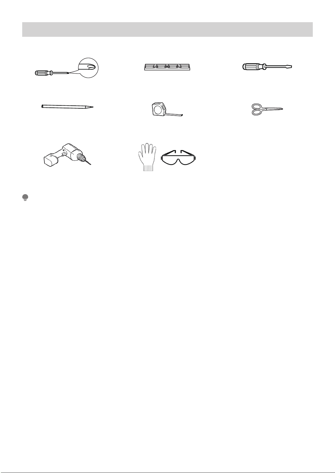
Pencil
Drill and 1/8” drill bit
Level
Ruler or tape measure
Proper PPE
Scissors or knife
Save carton and these Installation Instructions for future reference. The carton is the best way to store unit
during winter, or when not in use. If any piece of hardware is missing, DO NOT INSTALL THE PRODUCT, and call
customer service at 1-866-646-4332.
NOTE
Required Tools
Phillips screwdriver Flathead screwdriver
*Not Included
13
Install AC Support bracket and AC
Lip Window Flat Window
Lip
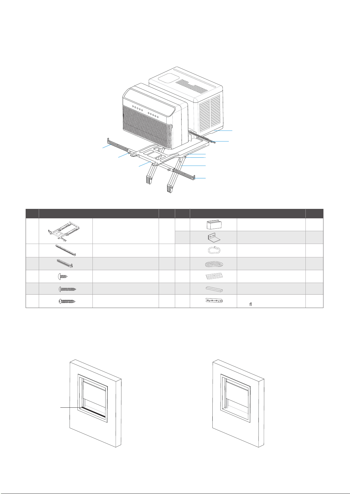
Installation exploded view:
Left Extension Arm
Right Extension Arm
Main Support
Spring Pin
Support arms
Adjusting button
Unit
Guide button
(Indoor side)
Anti-Tip Brackets
Installation Hardware:
Dierent type of Windows :
Mounting Hardware
Qty. Qty. NO. NO. Mounting Hardware
2
1
1
1A1
A2
A3
A4
A5
A6
B2
B1
B3
B4
B5
B6
B7
2
2
2
2
1
1
1
1
1
Flat Sill Adapter
(for
at sill windows)
Main Bracket
1/2” Type A Screw
1” Type A Screw
Side Arm Foam
Right Extension Arm – Short
(For 22”-26” windows)
Right Extension Arm
(For 26”-36” windows)
Window Sash Lock
Window Sash Foam
Window Sealing Foam
Bracket Sealing Foam
Additional Side Arm Foam
1.5” Type A Screw
*Indicates additional hardware provided in separate bags for certain models.
14
Determine whether the windowsill is flat or has a lip.
15
Right Extension Arm(A2)
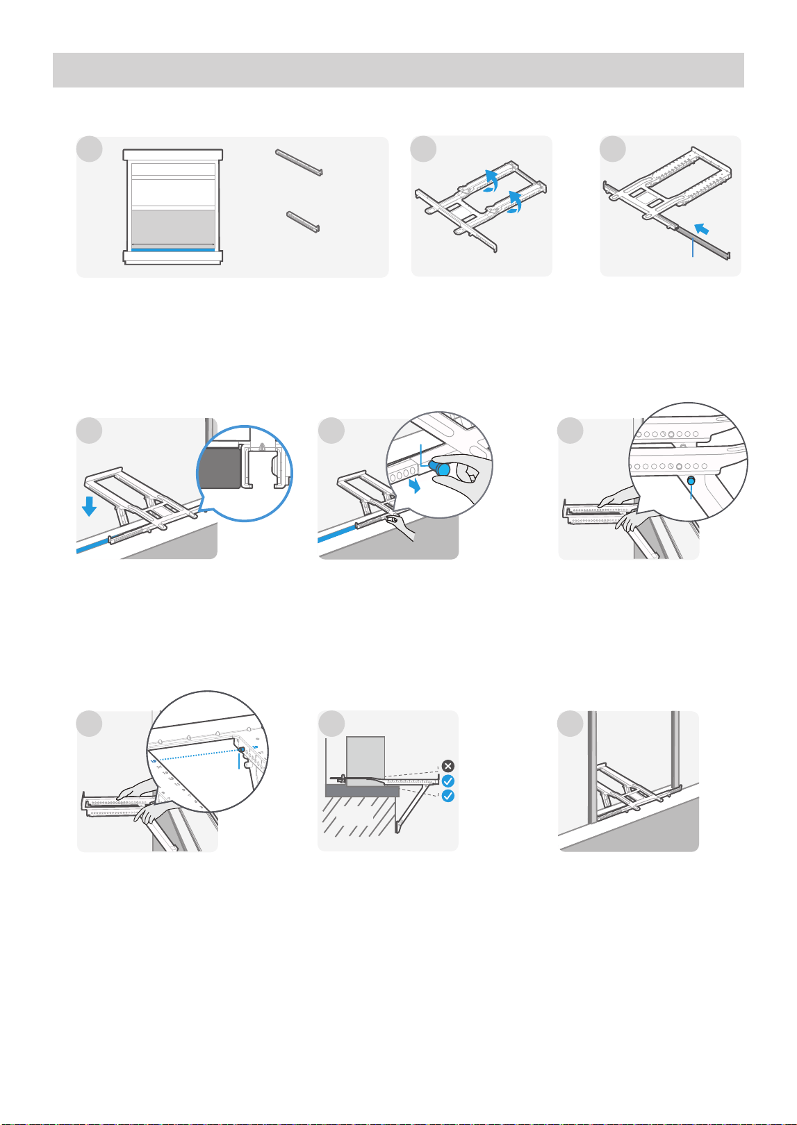
Step 1 : Install Support Bracket (for Lip Window)
Select the proper extension arm based on the width of
Use Right Extension Arm – Short for 22-26". windows,
and Right Extension Arm for 26-36". windows.
Remove the tape from
the bracket (A1) and
flip it over.
Place the bracket in the
center of the window.
Ensure the main support
is on the interior side of
the lip.
Ensure the guide button
are protruding from the
same number hole on
each arm.
Ensure the bracket is level or
angled slightly towards the
outside.
Pull the spring pin and
slide the arm out until it
contacts the window
casing. Repeat on the
other side.
Press the adjusting button on
each support arm to adjust
the legs until they rest against
the wall on the outside.
Insert the proper
extension arm in the
bracket as shown.
The bracket is ready for
the unit to be installed.
W
Wall
1
4
5
6
7
8
9
2
3
Right Extension
Arm – Short (A3)
Right Extension Arm (A2)
Adjusting
button
Guide
button
Pin
Side view
the window.
16
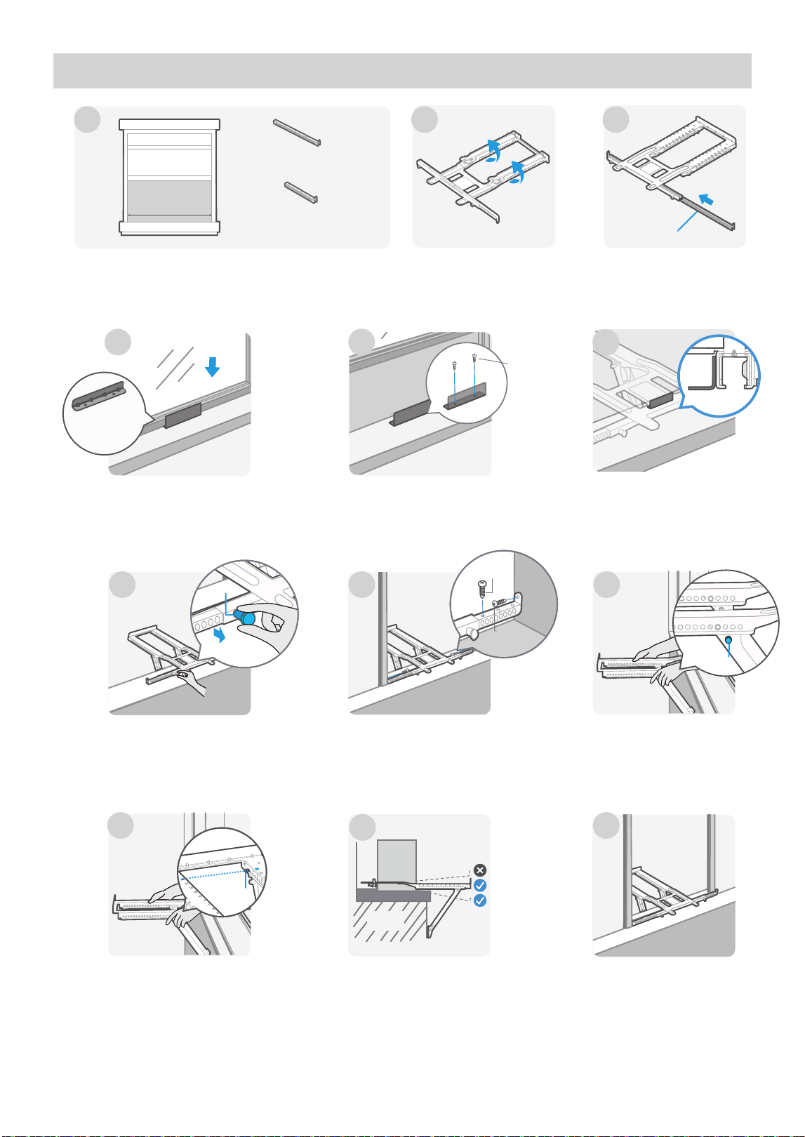
Step 1 : Install Support Bracket (for Flat Window)
The bracket is ready for
the unit to be installed.
Flat Sill
Adapter
(B7)
Flat Sill
Adapter
1” Type A
screws (A5)
Right Extension Arm (A2)
Remove the tape from
the bracket and flip it
over.
Insert the proper
extension arm in the
bracket as shown.
W
Pull the spring pin and
slide the arm out until it
contacts the window
casing. Repeat on the
other side.
Place the flat sill adapter (B7)
on the windowsill so that the
window sash lowers just
behind the vertical face of
the adapter.
Secure the flat sill adapter
(B7) to the window sill
using 1” (A5)Type A
screws.
Ensure the guide button
are protruding from the
same number hole on
each arm.
Ensure the bracket is level or
angled slightly towards the
outside.
4
5
Wall
11
7
10 12
Secure it to the windowsill using
the 1 –
1
/2” (A6) Type A screws on
both sides as shown. Use the
1
/2”
(A4) screws to fasten each
extension arm to the wall as
shown.
Press the adjusting
button on each support
arm to adjust the legs
until they rest against the
wall on the outside.
9
1 2
3
Right Extension
Arm – Short (A3)
Right Extension Arm (A2)
8
A4
A6
Adjusting
button
Guide
button
Place the bracket in the
center of the window,
with the main support
resting on the interior
side of the adapter.
6
Side view
Pin
Select the proper extension arm based on the width of
Use Right Extension Arm – Short for 22-26". windows,
and Right Extension Arm for 26-36". windows.
the window.
17
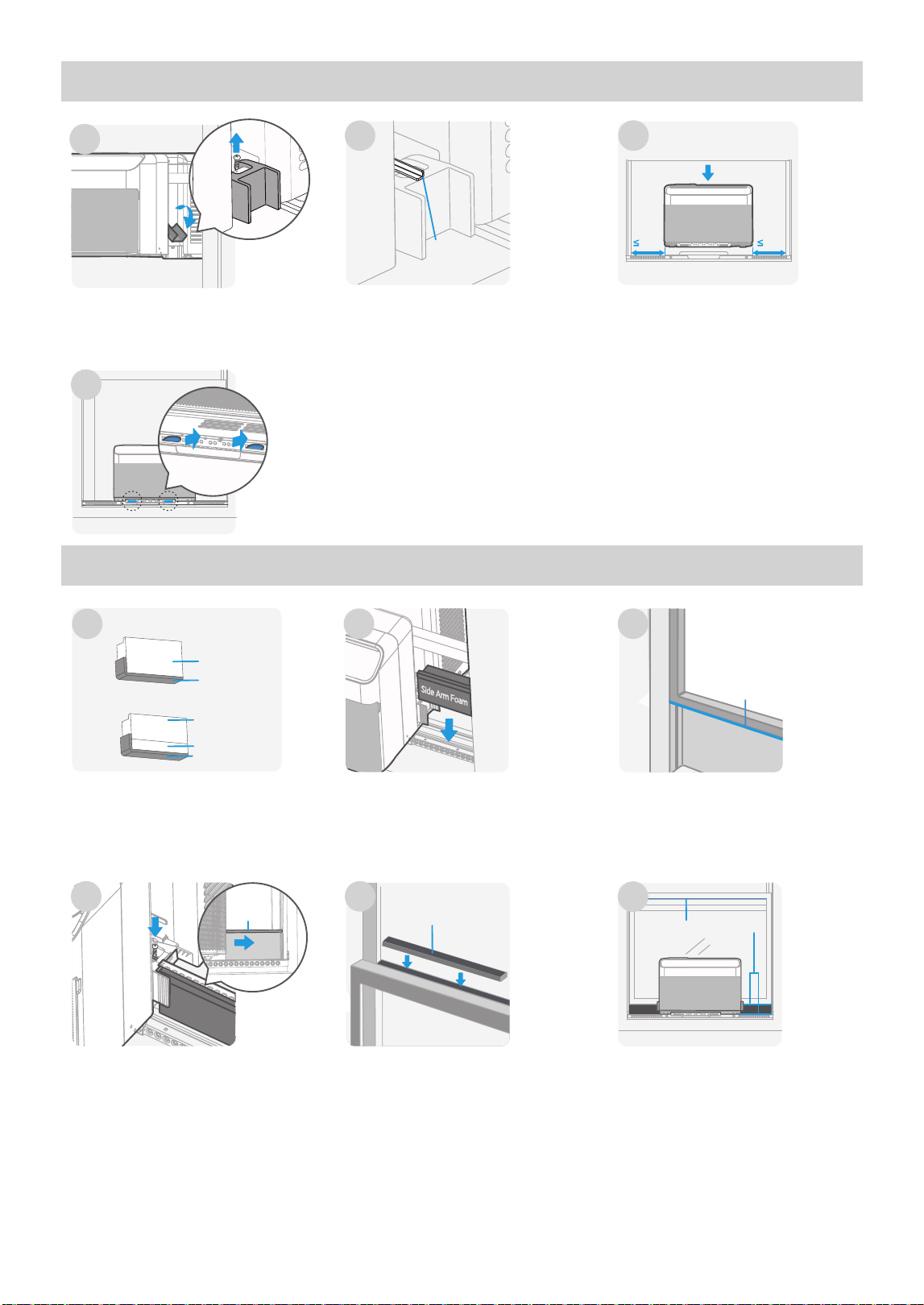
Step 3 : Foam Installation
Step 2 : Install Air Conditioner
Fold down both side arm
hinges and remove the screw
on each side. Save these
screws for the following step
3 and step 4 .
Remove the tape and slide
out the anti-tip arms from
each side about 1 inch
through the opening in the
side arm hinges.
1
Place the AC unit on the
bracket. Ensure it is centered in
the window.
8" 8"
3
2
4
Carefully slide the unit out until the
flanges on the bracket pass through the
grooves on the bottom of the unit.
Anti-Tip
Brackets
Cut window sash foam
(B3) and insert it in the
space between the upper
and lower sashes.
Installation is completed.The anti-tip brackets must
be extended into the
window track opening (the
vertical track the window
slides up and down in) until
they stop. Secure the
brackets in place using the
screws which were removed
in step 1 and step 2.
Insert the side arm foam
(B1) on each side.
Cut the adhesive window
sealing foam (B4) to the
width of the window and
attach it to the bottom of
the windowpane.
Cut the side arm foam (B1) to
length and attach the window
sealing foam (B4) and additional
side arm foam (B6) as shown
type.
Type A(For lip window)
Type B(For flat window)
1
5
2 3
4
Check for Gaps.
6
Window Sash Foam
(B3)
Window
Sealing Foam(B4)
B1
B4
B4
B6
B1
Anti-Tip
Brackets
above based on the window
OPERATION INSTRUCTIONS
Gurgle/Hiss
Gurgling or hissing noises may be heard
due to refrigerant owing through
evaporator during normal operation.
Sound of Rushing Air
High Pitched Chatter
High eciency compressors
may have a high pitched
sound during cooling cycle.
Vibration
Unit may vibrate and make
noise because of poor wall
or window construction or
incorrect installation.
Trickling Sound
Droplets of water hitting
condenser during normal
operation may cause a
trickling sound.
WARNING
To reduce the risk of re, electrical shock, or injury to people or property, read the SAFETY PRECAUTIONS
before operating this appliance.
Cooling Operation
Outdoor temp.: 64°F - 109°F / 18°C - 43°C
Indoor temp.: 60°F - 90°F / 16°C - 32°C
• The relative humidity of the room should be less than 80%. If the unit is used in a condition with a relative
humidity over 80%, there will be condensed water on the surface of the unit.
• Performance may be reduced outside of these operating temperatures.
NOTE
Always wait 3 minutes when turning the unit o and then on again, or when changing from cool to fan and back
to cool. This prevents damage from occurring to the compressor.
NOTE
Normal Operating Sounds
In front of the unit, the sound of
rushing air from the fan may be
audible.
18
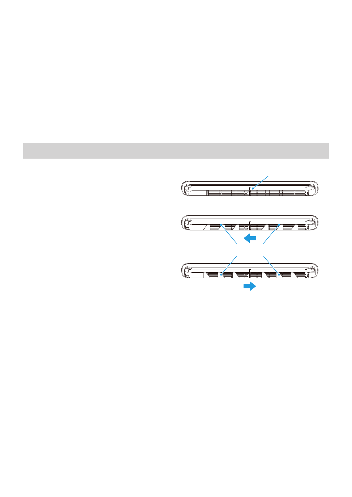
Air Directional Louvers
To begin operating the air conditioner, follow these steps:
Use SWING button for up/down direction
Adjust louvers for left/right direction
Air Direction
Move the louvers from side to side until the desired
left/right direction is obtained.
1. Plug in the air conditioner (be sure to follow the power cord instructions) on page 11.
2. Turn the power on to the air conditioner, using the ON/OFF button.
3. Set the thermostat to the coldest temperature setting.
4. Select the Cool mode setting.
Adjust the louver for comfortable air flow (see Air Directional Louvers).
Once the room has cooled, adjust the thermostat to the setting that is most comfortable.
Make sure the air flow inside and outside is not obstructed by anything.
5.
6.
7.
The louvers can direct airflow up or down and left or
right as needed. Use the SWING button to adjust the
up/down direction.
19
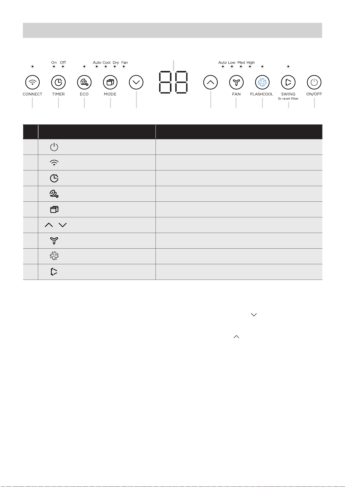
Features
Description
1 FFO / NO
2
Connect Function Press to initiate smart connection mode.
Press to turn unit on or off.
Press to set timer feature on/off.3
Timer
4
Energy Saver
Press to initiate this feature, which will maintain comfort
and save energy.
5
Mode Fuctions
Press to choose operating mode in a sequence that goes
from Auto, Cool, Dry and Fan.
6
Press to change temperature setting.
7
Fan Speed
Press to select the Fan Speed in four steps - Auto, Low,
Med or High.
8
9
Swing / Check Filter
Press to initiate the auto swing feature.
Press for 3 sec to turn off the clean filter reminder.
Up/Down Button
1. ON/OFF Button
2. CONNECT Button
and hold CONNECT and DOWN (
) buttons at the
and the LED DISPLAY shows ‘OF’ for 3 seconds,
press CONNECT and UP ( ) buttons at the same
time to turn on ction and the LED DISPLAY
shows ‘On’ for 3 seconds.
3. Timer Button: Auto Start/Stop Feature
TIMER Button
•
Connect fun
After Wireless Connection is successful, press
same time for 3 seconds to turn off CONNECT function
If connection (router) is successful within 8 minutes,
the unit will exit Wireless Connection mode automatically
and the CONNECT indicator illuminates.
If connection failed within 8 minutes, the unit
exits Wireless Connection mode automatically and the
CONNECT indicator does not illuminate.
FlashCool Function
2 3 4 5 7 8 9 16 6
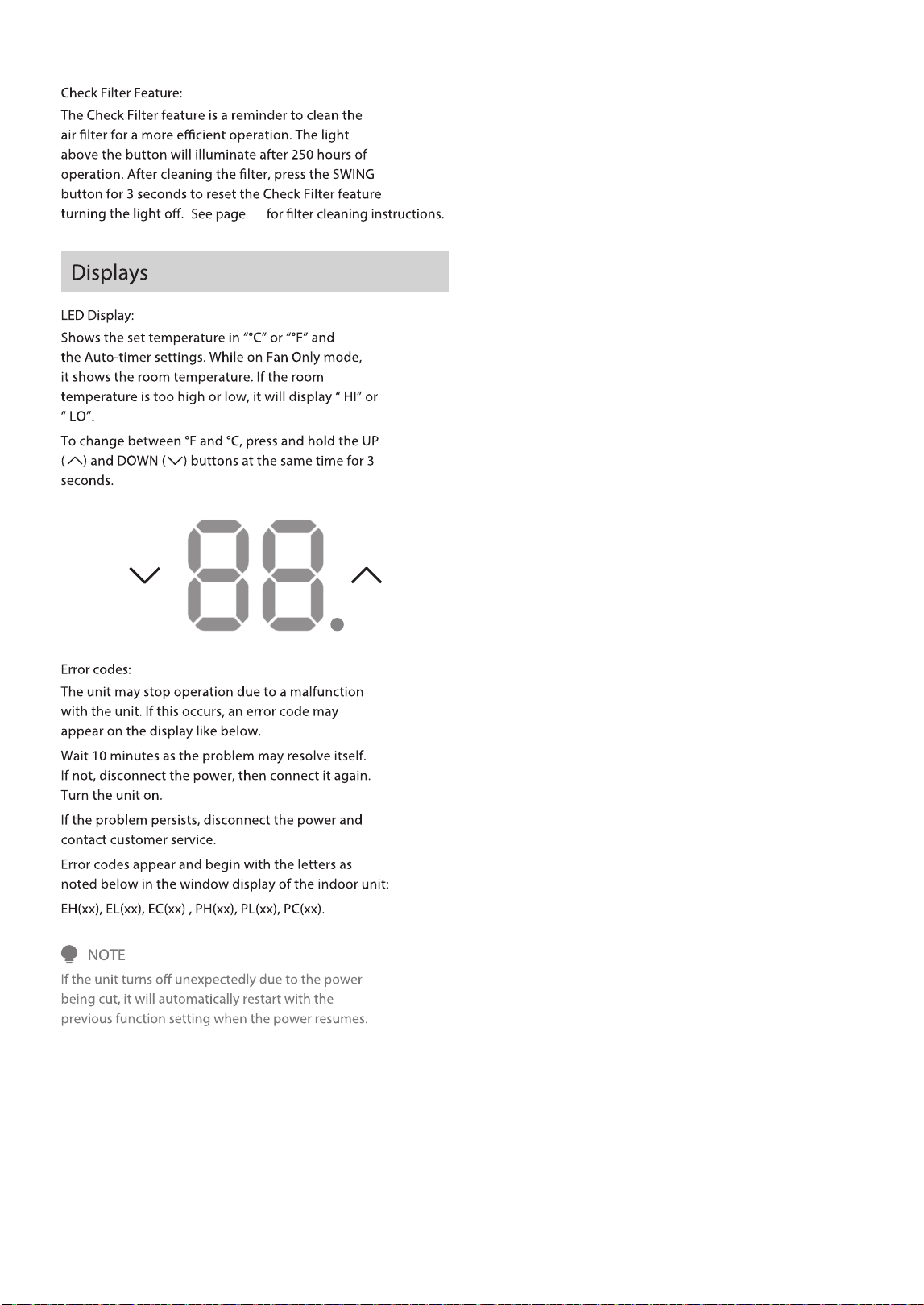
LED Display
Press to initiate the FlashCool mode.
The TlMER button enables the AUTO OFF and AUTO
ON features, which allows to set a desired time for
the unit to turn off or on automatically.
Press ON/OFF button to turn unit on or o.
When connecting the unit to Wireless Connection,
press the CONNECT button for 3 seconds to initiate
the Wireless Connection mode.
The display shows ‘AP’ to indicate the unit is in the
Wireless Connection mode. Refer to the Connect
section for further instructions.
20
6. UP/DOWN Button
Press UP ( ) or DOWN ( ) button to change
temperature setting.
7. FAN SPEED Button
Press Fan button to select the Fan Speed in four
steps - Auto, Low, Med or High. Each time the
button is pressed, the fan speed mode is shifted.
9. SWING Button
Use the SWING button to initiate the auto swing
feature for the outlet louver. When the auto swing is
on, pressing the SWING button can stop the louver at
the desired angle.
• While the unit is running, press the TIMER button
once to enable the AUTO OFF feature.
• Press the UP and DOWN buttons to choose the
To operate the AUTO OFF Feature
•
button once to enable the AUTO ON feature.
Press the UP and DOWN buttons to choose the
desired time, in hours, to turn the unit on.
To operate the AUTO ON Feature
• Turning the unit ON or OFF at any time or
adjusting the timer setting to 0.0 will cancel the
Auto Start/Stop timed program.
To cancel timer operation, press and hold the timer
button for 2 seconds until the beep/buzzer is heard.
NOTE
4. ECO Button
This function is available on COOL, DRY, and AUTO
(only AUTO-COOLING and AUTO-FAN) modes.
The fan will continue to run for 3 minutes after the
The fan then cycles on for 2 minutes at 10 minute
intervals until the room temperature is above the set
temperature, at which time the compressor turns back
on and Cooling Starts.
5. MODE Button
• To choose the operating mode, press the MODE
selected in a sequence that goes from Auto, Cool,
Dry and Fan. The indicator light beside the button
will be illuminated and remain on once that mode
is selected.
•
power button, the unit will automatically switch
on the Energy Saver Function for the following
modes: Cool, Dry, Auto.
To operate on AUTO
• In AUTO mode, the air conditioner will automatically
select either cooling or fan-only operation based on
the selected temperature and the current room
temperature.
• The air conditioner will automatically control the
room temperature according to the set temperature.
• In this mode, the fan speed cannot be adjusted
and is automatically controlled based on the
temperature setting and room temperature.
To operate on COOL mode:
• Choose Cool Mode to set the cooling function.
Use the UP (
) or DOWN ( ) buttons to choose
the desired temperature. When Cool Mode is
selected, the fan speed can be adjusted by
pressing the fan button.
To operate on DRY mode:
• In this mode, the air conditioner will generally
space is a closed or sealed area, some degree of
cooling will continue. On Dry mode, the fan speed
is not adjustable.
operate as a dehumidifier. Since the conditioned
To operate on FAN mode:
• Use this function only when cooling is not desired,
such as for room air circulation. Any fan speed can
be selected.
• In Fan Only mode, the temperature cannot be
room temperature, not the set temperature as in
the cooling mode.
mode:
8. FLASHCOOL Button
Press to turn FlashCool on or off. In FlashCool mode, the air
speed to provide additional cooling to reach the temperature
setpoint. Once the setpoint is reached, the unit will continue to
run the fan in high speed and stay in FlashCool mode.
FlashCool mode will end if:
• Button is pressed again
• The unit is turned off
• The mode is changed
• The fan speed is changed
• Sleep mode is enabled.
button. Each time the button is pressed, a mode is
adjusted and the display will show the actual
conditioner will run at the highest fan speed and compressor
21
41
22
REMOTE CONTROL AND SMART APP SETUP
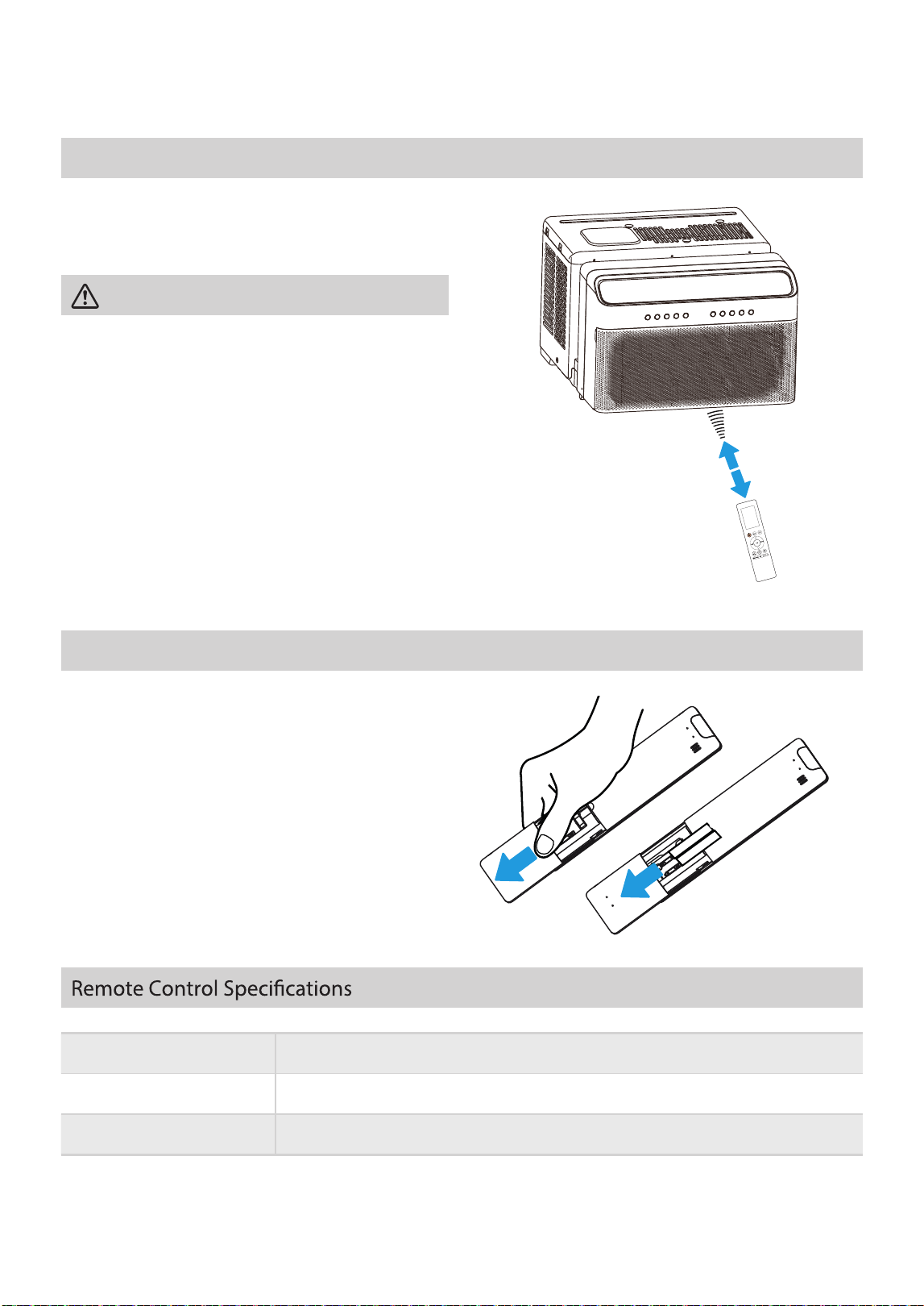
Location of the remote control
Inserting and Replacing Batteries
Use the remote control within a distance of 26 ft. (8m)
from the air conditioner, pointing it towards the unit.
The unit will beep when it receives a signal.
26 ft (8 meters)
CAUTION
• The air conditioner will not operate if curtains,
doors or other materials block the signals from the
remote control to the unit.
• Prevent any liquid from spilling onto the remote
control. Do not expose the remote control to
direct sunlight or heat.
• If the infrared signal receiver on the indoor unit is
exposed to direct sunlight, the air conditioner may
not function properly. Use curtains to prevent the
sunlight from falling on the receiver.
• If other electrical appliances react to the remote
control, either move these appliances or consult
The unit comes with 2 AAA batteries.
Put the batteries in the remote control before use.
1. Slide the back cover of the remote control
outward to reveal the battery compartment.
2. Insert the batteries, ensuring the (+) and (-)
ends align with the symbols inside the battery
compartment.
3. Slide the battery cover back into place.
Rated Voltage 3.0V (Dry batteries R03/LR03x2)
Signal Receiving Range 26 ft (8 m)
Environment -5 °C ~ 60 °C (23°F ~ 140°F)
the local dealer.
23

Battery Warning
•
•
•
•
•
•
Do not mix old and new batteries, or batteries of different types.
Always purchase the correct size and grade of battery most suitable for the intended
use.
Replace all batteries of a set at the same time.
Clean the battery contacts and those of the unit before installing the batteries.
Remove batteries from the remote control when not in use for an extended period.
Remove used batteries promptly.
Notes
The unit could comply with the local national regulations.
In Canada, it should comply with CAN ICES-3(B)/NMB-3(B).
In USA, this unit complies with part 15 of the FCC Rules. Operation is subject to
the following two conditions:
(1) This unit may not cause harmful interference, and
(2) This unit must accept any interference received, including interference that may
cause undesired operation.
This unit has been tested and found to comply with the limits for a Class B digital
device, pursuant to part 15 of the FCC Rules. These limits are designed to provide
reasonable protection against harmful interference in a residential installation. This
unit generates, uses and can radiate radio frequency energy and, if not installed and
used in accordance with the instructions, may cause harmful interference to radio
communications. However, there is no guarantee that interference will not occur in
a particular installation. If this unit does cause harmful interference to radio or
television reception, which can be determined by turning the unit off and on, the
user is encouraged to try to correct the interference by one or more of the following
measures:
Reorient or relocate the receiving antenna.
Increase the separation between the unit and receiver.
Connect the unit into an outlet on a circuit different from that to which the
receiver is connected.
Consult the dealer or an experienced radio/TV technician for help.
Changes or modifications not approved by the party responsible for compliance
could void user’s authority to operate the unit.
Dispose of used batteries according to local laws and regulations.
•
24
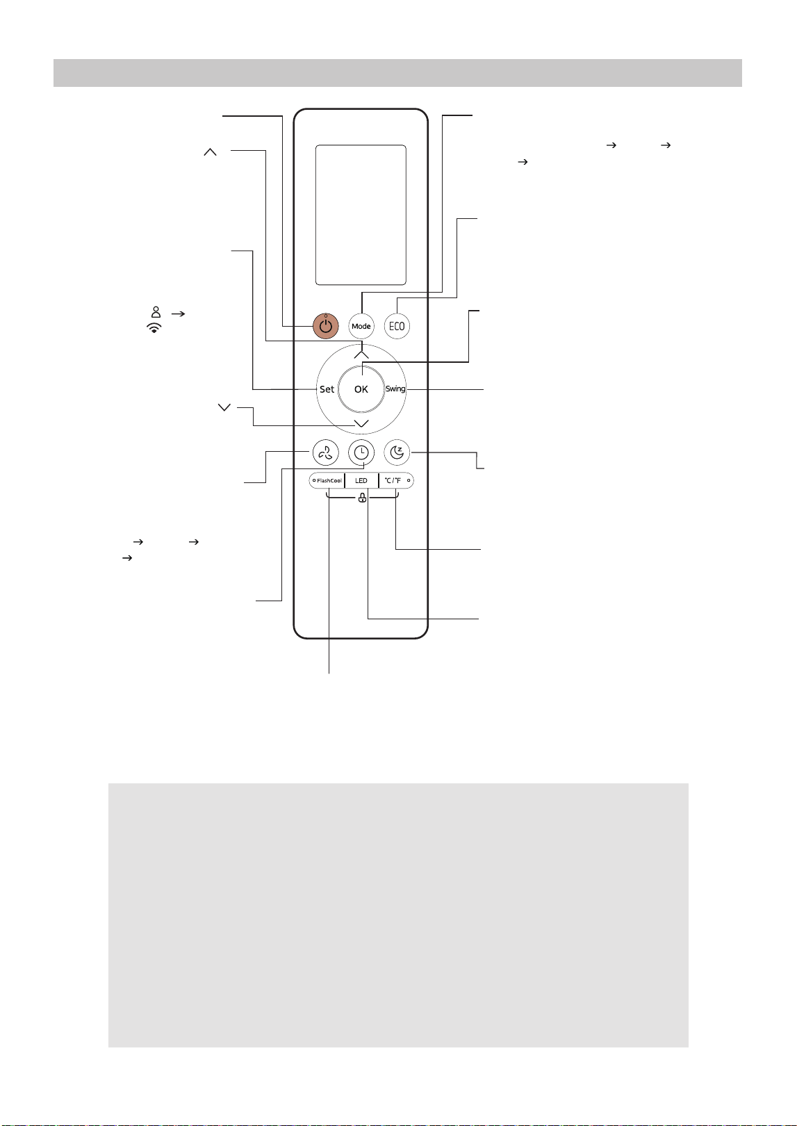
Buttons and Functions
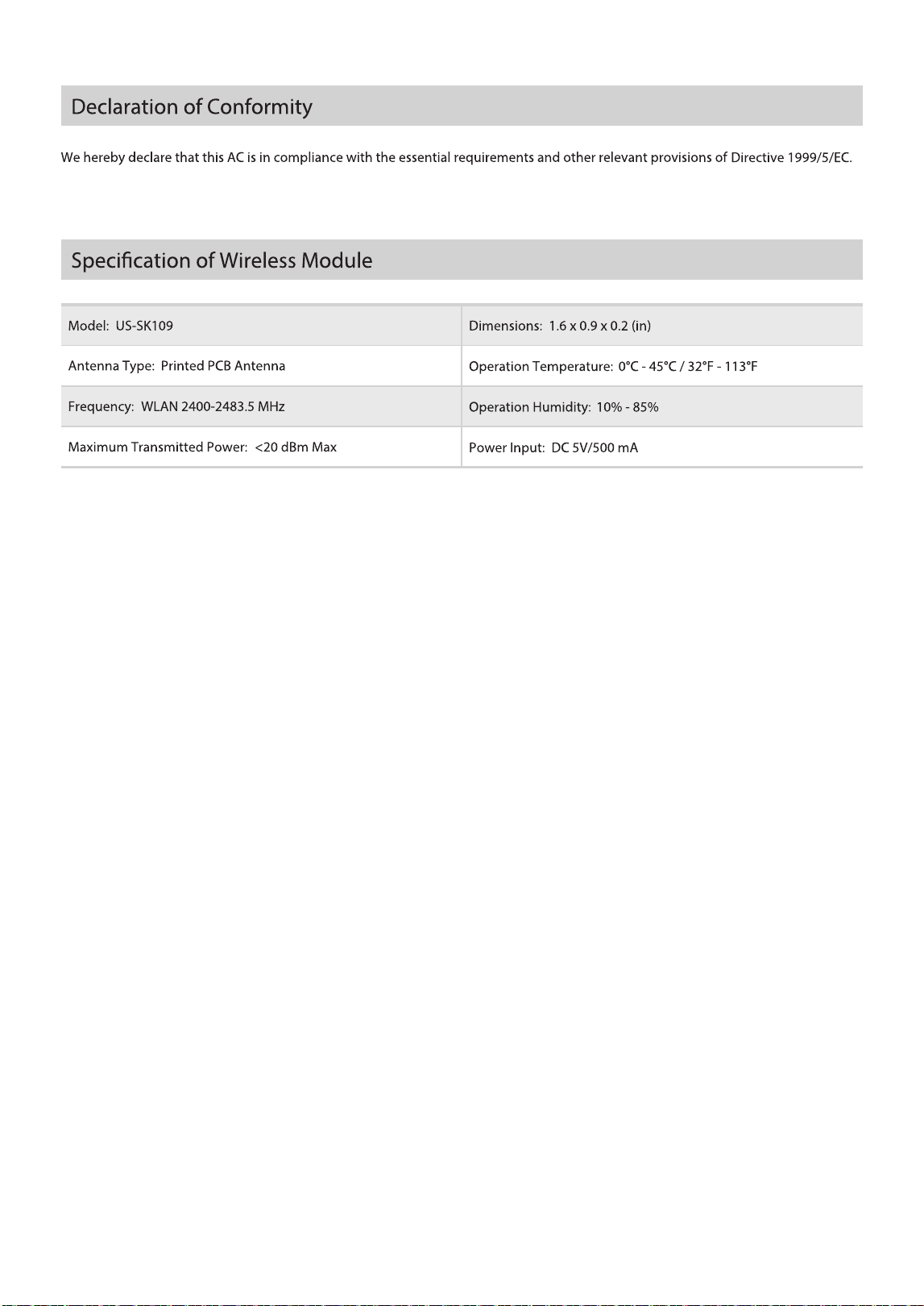
Supplier's Declaration of Conformity
47 CFR § 2.1077 Compliance Information
Unique Identifier:
Responsible Party U.S. Contact Information
Midea America Corporation
300 Kimball Dr
Parsippany NJ
07054
This device complies with Part 15 of the FCC Rules. Operation is subject to the
following two conditions: (1) This device may not cause harmful interference, and
(2) this device must accept any interference received, including interference that
may cause undesired operation.
Telephone number or internet contact information: Midea.com/us
FCC Compliance Statement ( products subject to Part 15)
Midea brand, RG10A16(B2S)/BGCEFU1
SLEEP
Saves energy during sleeping
hours (see How to Use Basic
Functions for instructions).
Enables unit to reach preset
temperature in shortest possible
FAN SPEED
SWING
Starts and stops the horizontal
louver movement.
ON/OFF
SET
Turns the unit on or off.
MODE
OK
FlashCool
Scrolls through operation modes
as follows:
AUTO
COOL
DRY
FAN
TIMER
Increases temperature in
1°F (1°C) increments.
Max. temperature is
86°F (30°C).
TEMP
TEMP
Used to confirm the selected
functions
Decreases temperature
in 1°F(1°C) increments.
Min. temperature is
60°F(16°C).
Scrolls through operation
functions as follows:
C SENSE ( )
AP Mode( )
The selected symbol will
flash on the display area,
press the OK button to
confirm.
Sets timer to turn unit
on (see How to Use Basic
Functions for instructions).
°C/°F
The temperature display
between the °C&°F.
ECO
AUTO LOW
MED HIGH
Selects fan speeds in
the following order:
LED
Press this button to activate
energy-saving mode. Press it
again to deactivate the function.
Turns LED display and buzzer on
or off (depending on the model).
(see How to Use Basic Functions
for instructions)
25
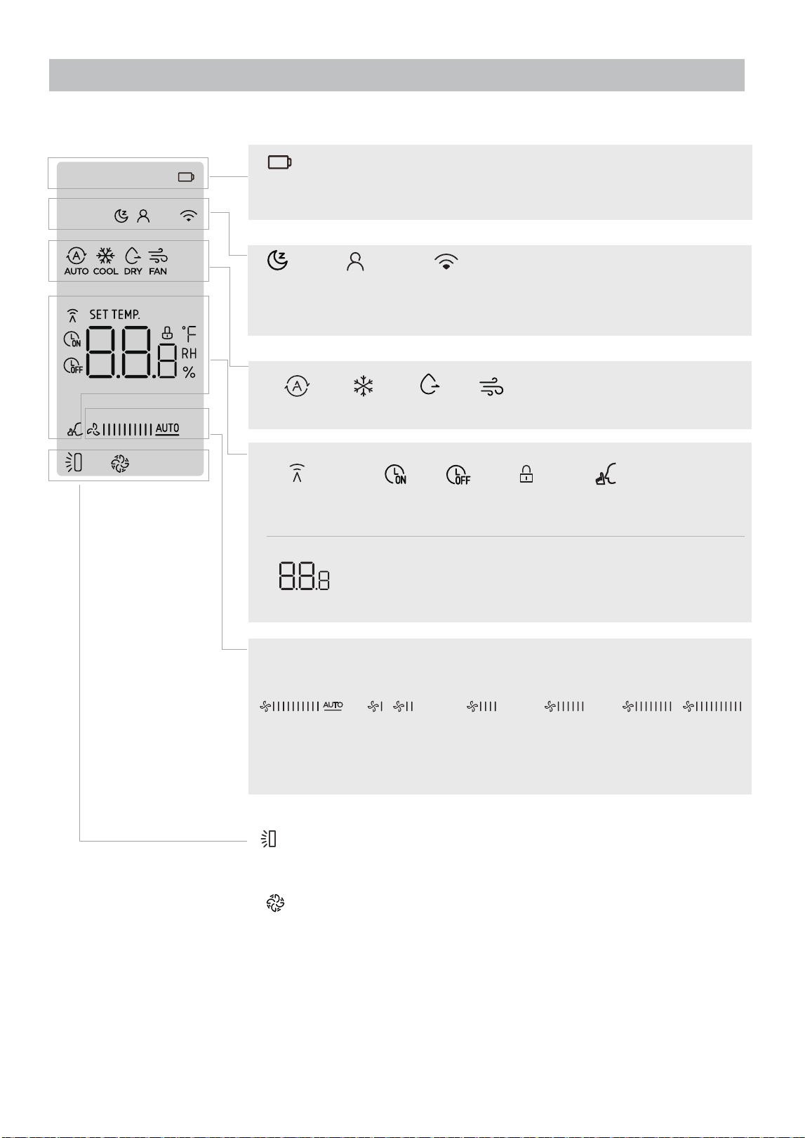
Information is displayed when the remote controller is powered on.
Note:
All indicators shown above are for information purposes. During the actual operation, only the
relevant indicators will be shown on the display.
Remote Screen Indicators
Temperature/Timer/Fan speed display
Displays the set temperature by default, or fan speed
or timer setting when using TIMER ON/OFF functions.
Low battery
(If flashes)
AUTO
COOL
DRY
FAN
MODE display Displays the current mode
Transmission
Indicator
Timer
OFF
Lock
Feature
Timer
ON
Silence
Feature
SILENCE
1%
NOTE: The fan speed can not be adjusted in AUTO or DRY mode.
2-20%
FAN SPEED
LOW MED
21-40% 41-60%
HIGHAUTO
61-80%
81-100%
Horizontal louver swing
FlashCool mode
[*]: Model dependent
Sleep
mode
Wireless
control
*
Comfort
Sense
26
5 hours later
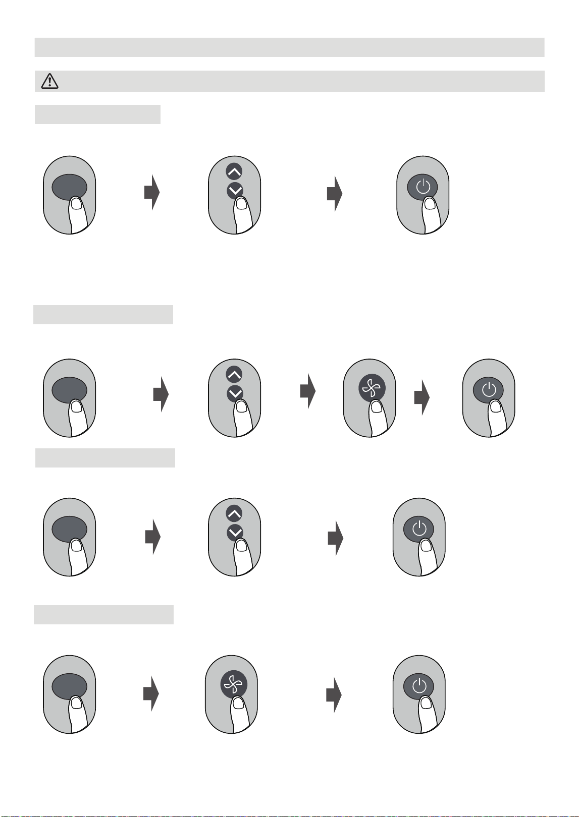
How to Use Basic Functions
AUTO Mode
COOL Mode
DRY Mode
Select AUTO mode
NOTE:
1. In AUTO mode,
the unit will automatically select the COOL, FAN function based on
the set temperature.
2. In AUTO mode, fan speed cannot be set.
Turn on the air conditioner
Select DRY mode Turn on the air conditioner
FAN Mode
Select FAN mode Turn on the air conditioner
Select COOL mode
Set the temperature
Turn on the air
conditioner
Set the fan speed
Set the fan speed
NOTE:
In DRY mode, fan speed cannot be set since it has already been automatically controlled.
NOTE:
In FAN mode, fan speed cannot be set. As a result, no temperature displays on the remote screen.
Before operation, please ensure the unit is plugged in and power is available.
Note:
MODE
MODE
MODE
MODE
Set the temperature
Set the temperature
27
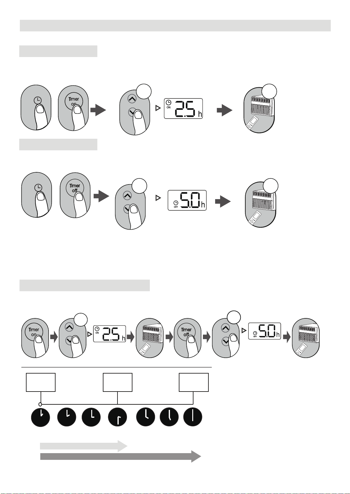
Setting the TIMER
TIMER ON setting
TIMER OFF setting
Example of TIMER sequence
TIMER ON/OFF - Set the amount of time after which the unit will automatically turn on/o.
Press TIMER ON button to
initiate the ON sequence.
Press up or down button for
multiple times to set the desired
time to turn on the unit.
Point remote to unit and wait
1 second, the TIMER ON will be
activated.
x5
1sec
Press Temp. up or down button for
multiple times to set the desired
time to turn off the unit.
Press TIMER OFF button to
initiate the OFF time sequence.
Point remote to unit and wait
1 second, the TIMER OFF will be
activated.
1sec
x10
NOTE:
1. When setting the TIMER ON or TIMER OFF, the time will increase by 30 minutes increments
with each press, up to 10 hours. After the 10th hour, the timer increases in 1-hour increments up
to 24 hours. (i.e. Pressing the button 5 times sets the timer to 2.5 hours, and pressing 10 times sets
it to 5 hours. The timer will reset to 0.0 after reaching 24 hours.)
2. Cancel either function by setting its timer to 0.0h.
Current
time 1PM
2:00PM 3:00PM
4PM 5PM
6PM
Timer starts
Unit turns
ON
Unit turns
OFF
2.5 hours later
5 hours later
3:30PM
1:00PM, to set the timer as above
steps, the unit will turn on 2.5h
later (3:30PM) and turn off at
6:00PM.
Note that the time periods set for both functions are based on hours from the current time.
xn
xnxn
or
or
TIMER
TIMER
28
i.e. If current timer is
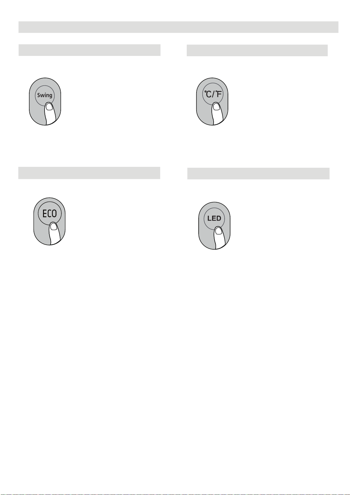
How to Use Advanced Functions
The horizontal louver will swing up and down
automatically when pressing Swing button.
Press again to make it stop.
Swing function
ECO function
Press ECO to turn on the energy saver function.
This function is available on COOL, DRY,
AUTO modes.
Press this button will alternate the temperature
display between the °C & °F.
°C/°F
LED DISPLAY
Press this button to turn on and turn off the
display on the indoor unit.
29
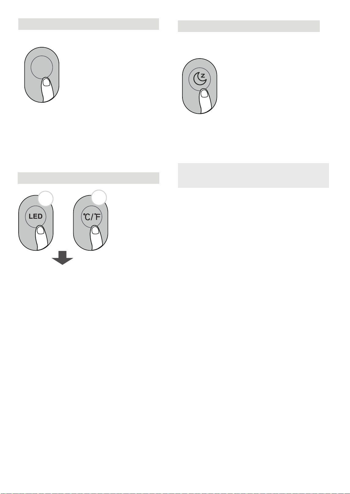
LOCK function
5s
5s
+
Press together LED button and °C/°F button
at the same time more than 5 seconds to
activate Lock function.
All buttons will be unresponsive except for
these two. Press and hold them for two
seconds to disable the lock function.
SLEEP function reduces energy usage when
activated by adjusting the temperature settings.
Note:
The SLEEP function is not available in
FAN or DRY mode.
SLEEP Function
FlashCool Function
Press FlashCool button
FlashCool
Press this button in COOL mode to activate the
FlashCool function. In this mode, the unit will
rapidly lower the room temperature.
30
or
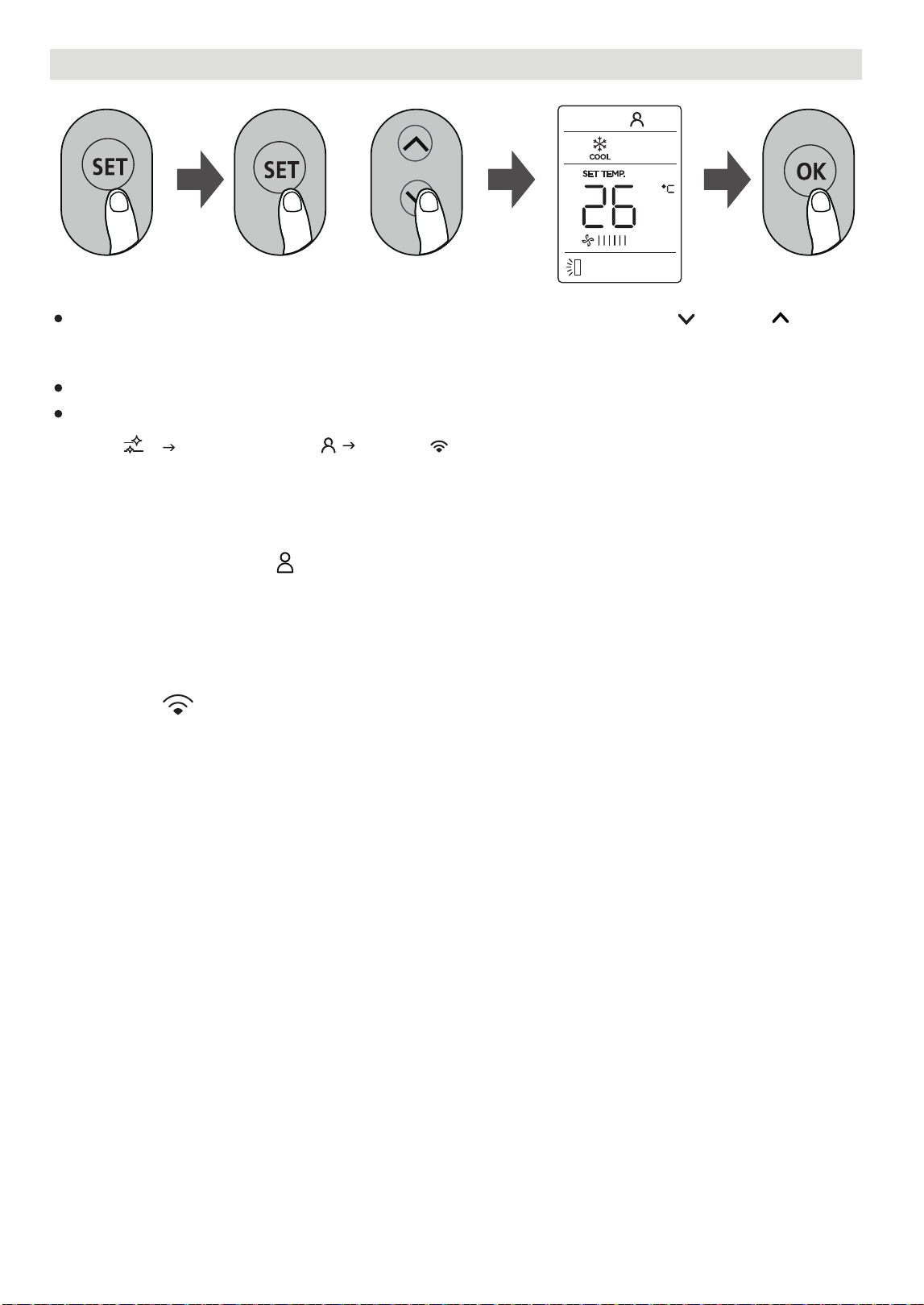
SET function
Press the SET button to enter the function setting, then press SET button or TEMP or TEMP
button to select the desired function. The selected symbol will flash on the display area, press the
OK button to confirm.
Press the SET button to scroll through operation functions as follows:
AP function ( ) :
Choose AP mode to do wireless network configuration. For some units, it doesn’t work by pressing
the SET button. To enter the AP mode, continuously press the LED button seven times in 10
seconds.
Clean COMFORT SENSE ( ) AP mode( )
[ ]: Model dependent.
*
*
*
COMFORT SENSE function ( ) :
The COMFORT SENSE function allows the remote control to measure the temperature at its location and
send this data to the air conditioner every 3 minutes. In AUTO, COOL modes, using the remote
control's temperature readings instead of those from the indoor unit helps optimize the temperature
around the user for maximum comfort.
( )
31
To cancel the selected function, please follow the same procedures outlined above.
32
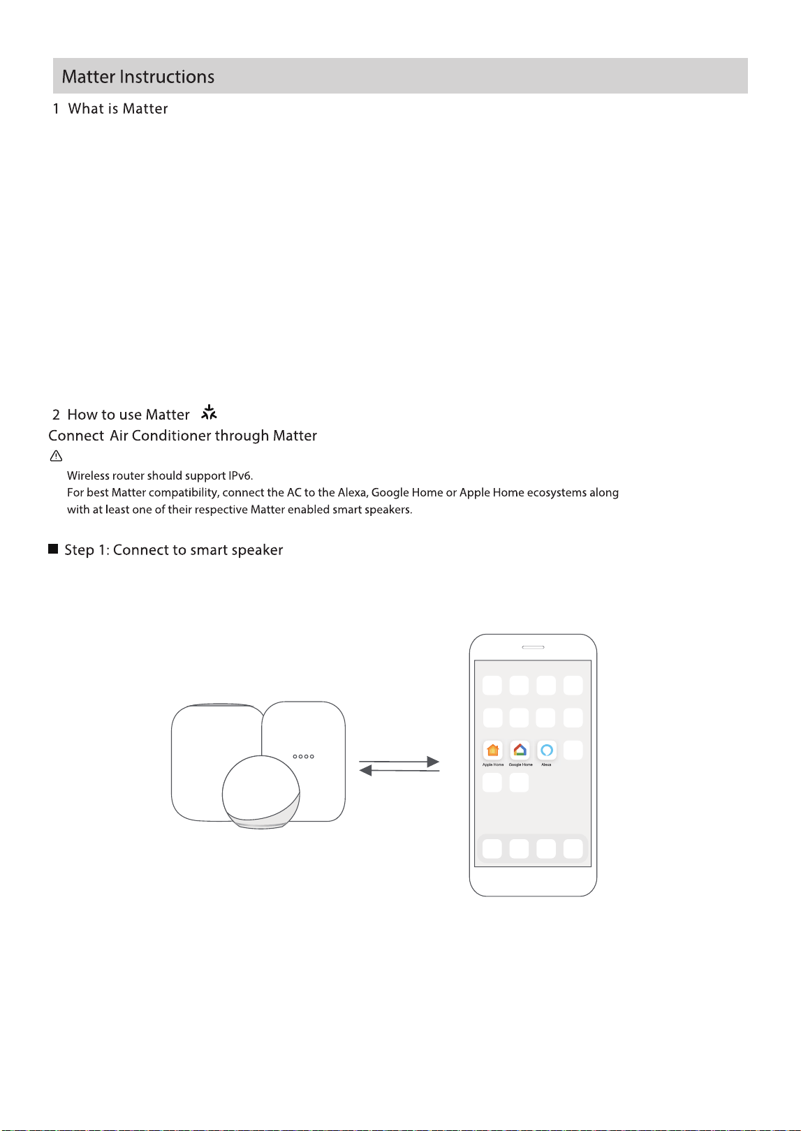
and Apple Home) to speak the same language thus creating exciting new features and use cases.
Matter is a connectivity technology that unifies the smart home by allowing devices and ecosystems (such as Alexa, Google Home
Top industry brands such as Apple, Google, Amazon, Midea and others collaborated to create Matter which provides the following
benefits:
- Seal of approval that smart home devices will work seamlessly together – today and tomorrow.
- Familiar and consistent process to make setup simple, reliable, and secure.
- Consistent and responsive local connectivity that still works if the internet is down.
- Extra layer of cybersecurity for peace of mind.
- If a Matter-enabled smart speaker and/or display is available, refer to the "How to use Matter" instructions below.
- If a Matter-enabled smart speaker and/or display is not available, Matter cannot be used at this time. Full functionality can still
Make sure the mobile device is connected to the correct wireless router.
Select the preferred platform (Alexa, Google Home, or Apple Home) and ensure that a Matter-enabled product
(such as a smart speaker) from that platform is connected to the wireless router.
To use Matter, at least one Matter-enabled smart speaker or display from Amazon, Google, or Apple is required, along with the
respective app for that device.
33
be achieved using the SmartHome app. For details, see the "How to use SmartHome app" section on page 37.
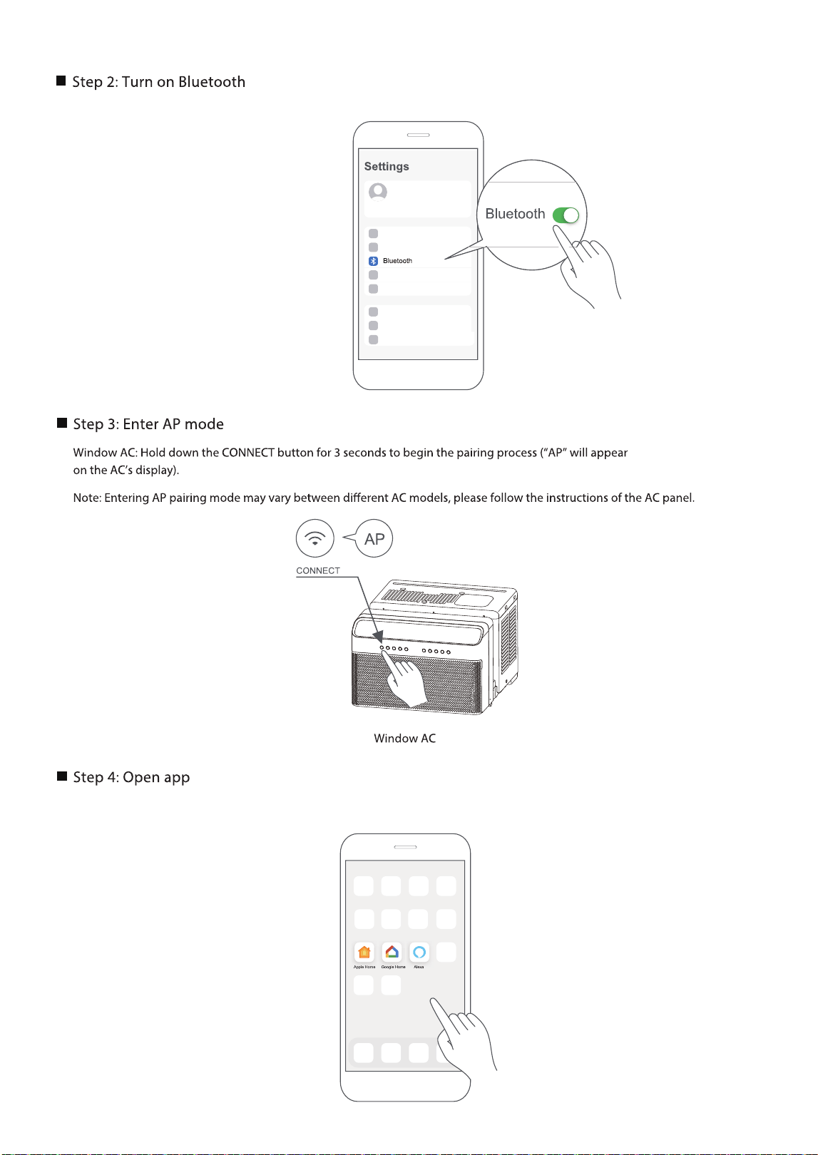
Turn on Bluetooth on the mobile device.
Open the Alexa, Google Home, Apple Home app on the mobile device.
34
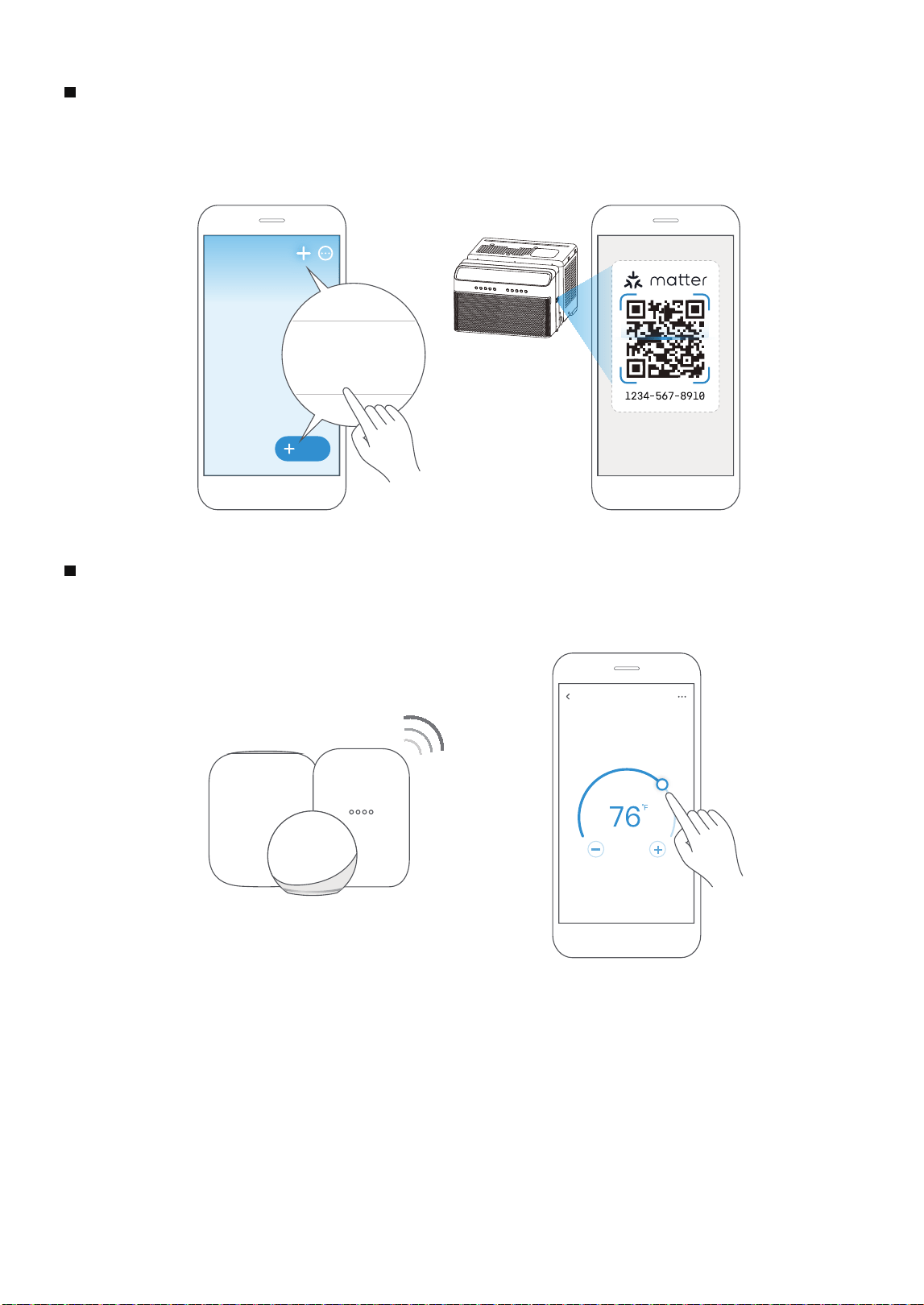
Tap the “+” and “Add Device/Accessory” or tap "+Add" in the app and then select Matter device and scan
the Matter QR code found on the side of the AC device. Follow the respective instructions in the Alexa,
Google Home or Apple Home app to complete the pairing process.
Step 6: Control device
Air conditioner
Add
Add Device/Accessory
scan
Matter QR code
found on the side of the device
Step 5: Scan Matter QR code
After a successful pairing, the unit's temperature and mode settings etc. can be controlled through the respective platform
app or smart speaker.
35
App & Smart Speakers can support Matter only when using these versions or above.
NOTE:
Setup processes and features may vary between ecosystems.
Make sure the Matter enabled app is up to date to ensure the best experience.
Device software updates can be accomplished through the SmartHome app.
9094439556
Google Play services min version: 22.36.15
Google Home app (GHA) min version: 2.58.24.1-dogfood
Google Hub rmware min version: 1.56.324896
(appears on hub as Chromecast rmware version)
2.2.536317
16.5
Device Version
iOS16.5 iPhone
Apple Home
Pod
Alexa Echo
Device
Android
Google
Home Hub
Alexa App
Periodically, the software will be updated to improve experience.
36
Ensure that the mobile phone is connected to the wireless network. Bluetooth must be turned on.
The device must also be powered up.
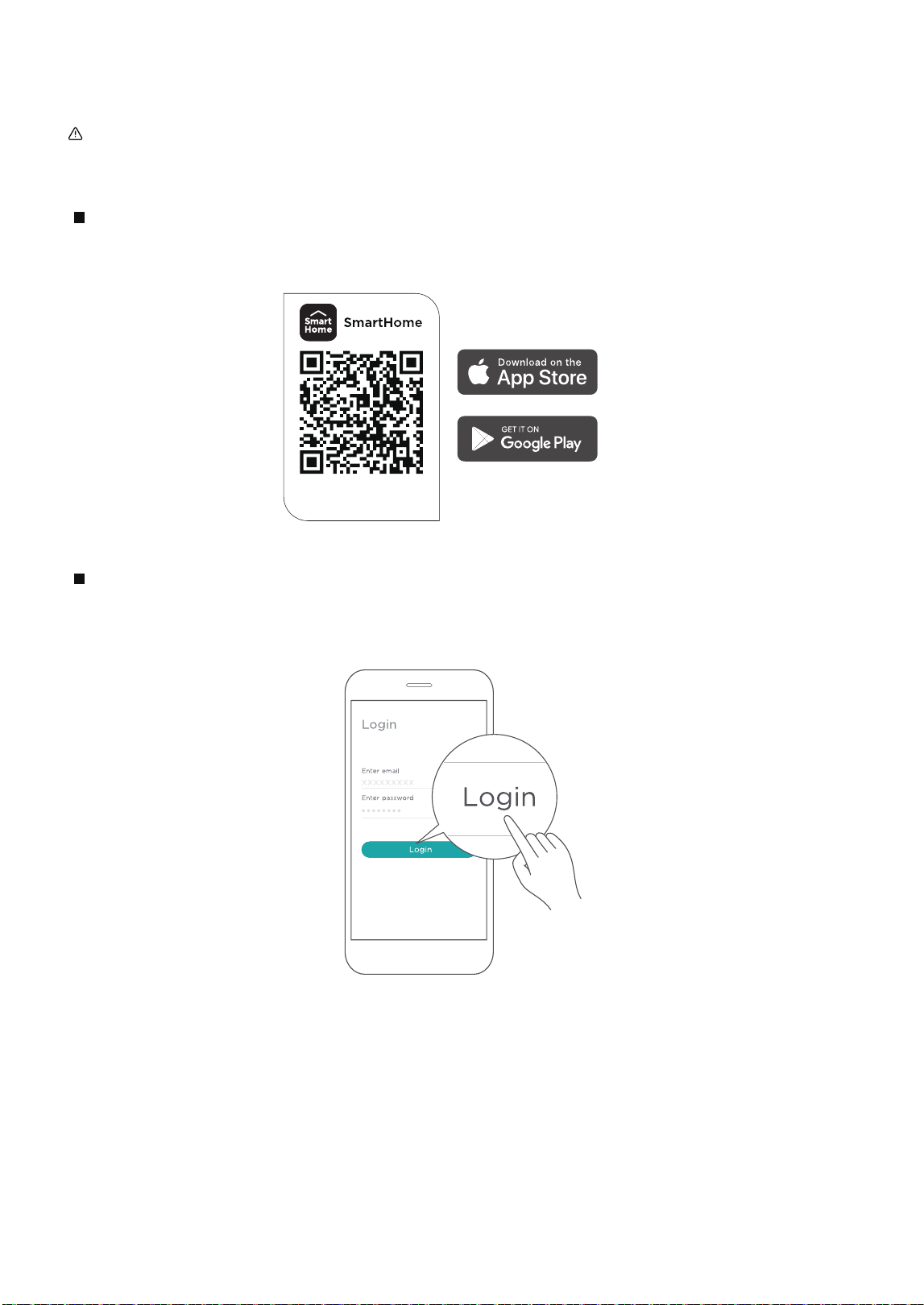
Scan the QR code below to download the SmartHome app from the app store or search for it directly on the
Google Play Store or Apple's App Store.
Step 1: Download the SmartHome app
Open the SmartHome app. Log in if an existing SmartHome account is available or create a new account.
Alternatively, use a third-party login platform.
Step 2: Log in
Download the app
& activate product
3 How to use SmartHome App
37
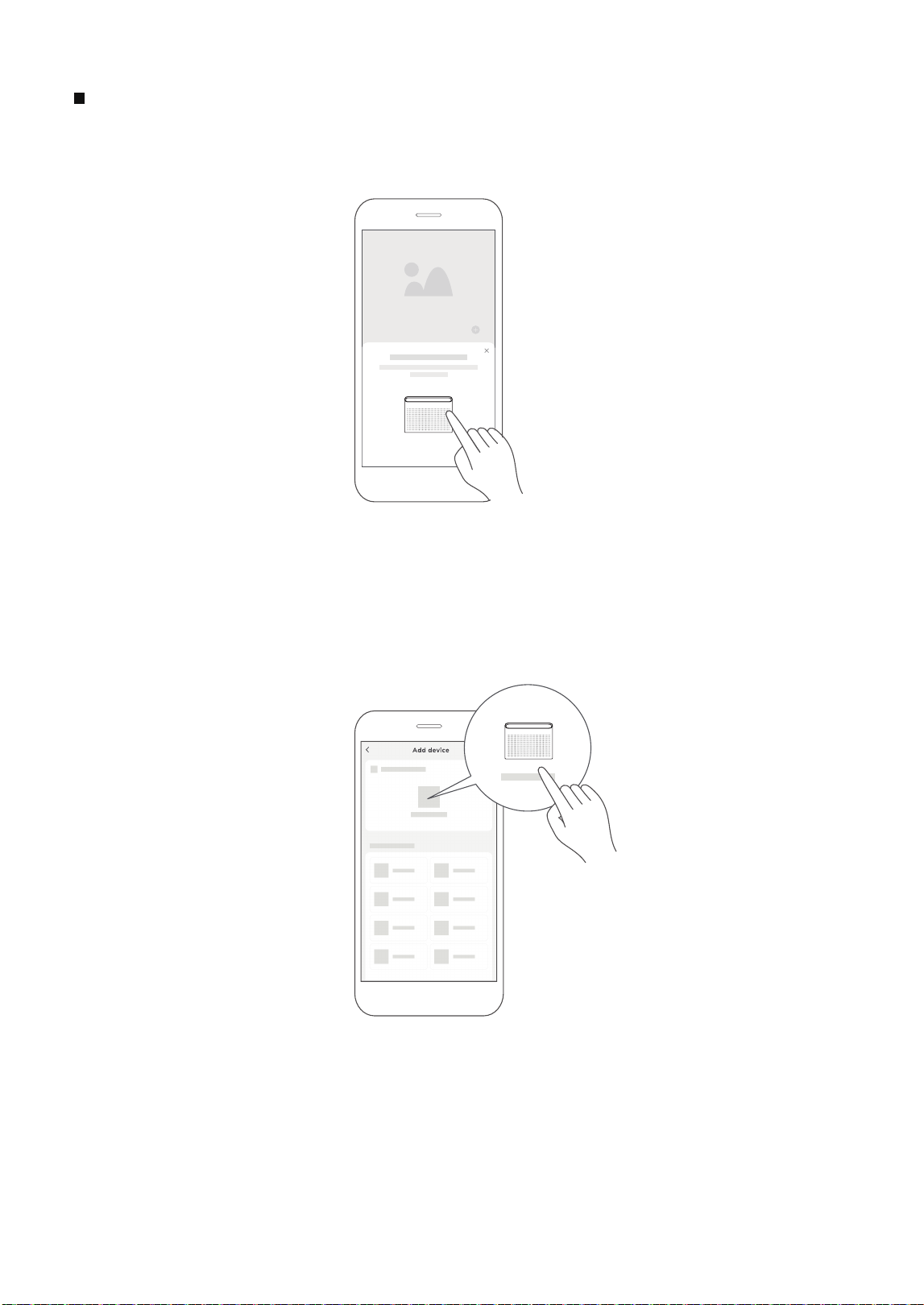
Step 3: Connecting the device
1) Upon logging in, a message stating "Smart devices discovered nearby" may appear. Tap to add the device.
2) If the message does not appear, tap on "+" and select the device from the list of nearby available devices.
If the device is not listed, add it manually by first selecting the device category, such as Window AC.
38
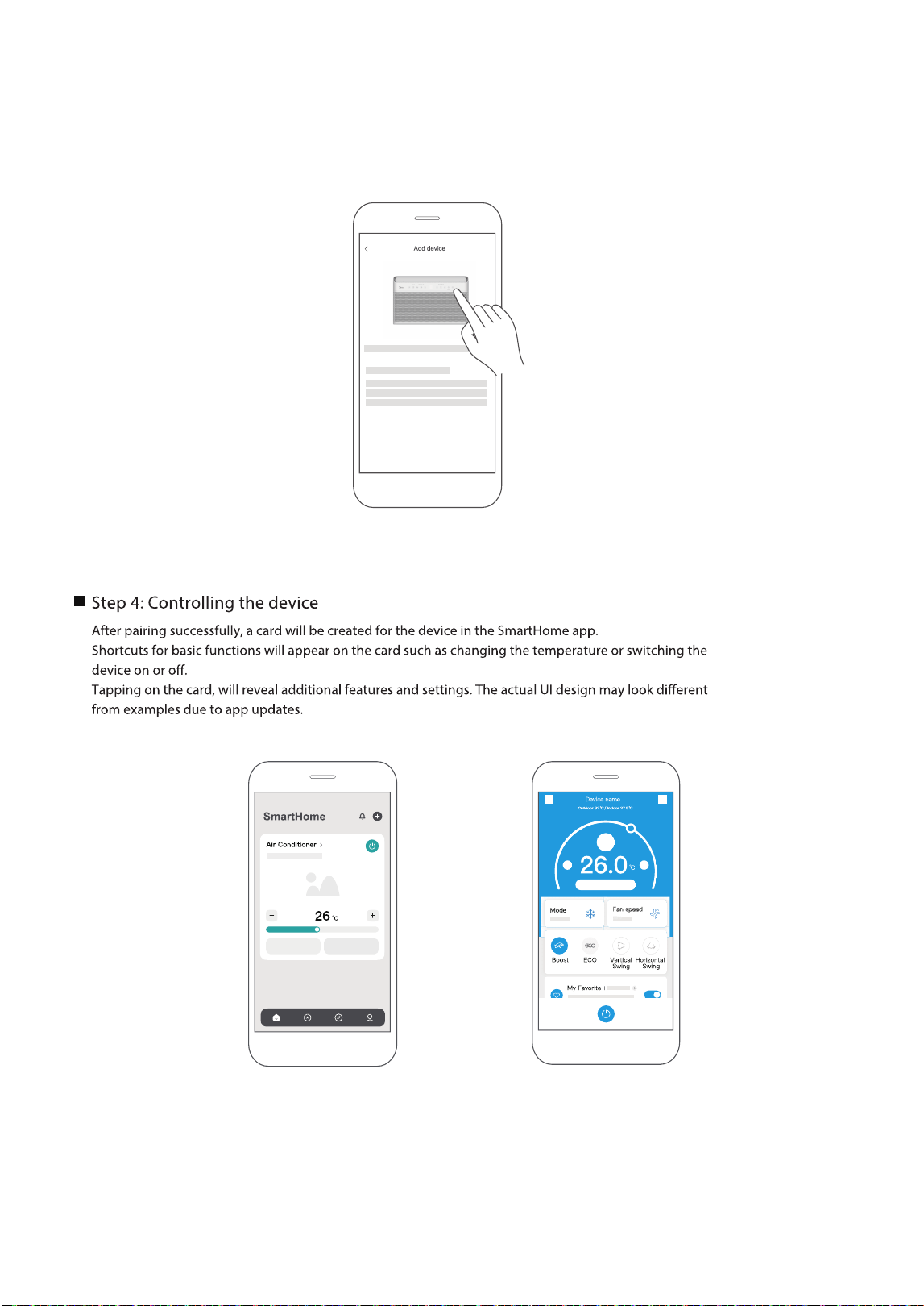
3) Follow the app's instructions to connect the device to the wireless network. If the connection fails, refer to the
additional instructions provided in the app.
(Fig. 1)
(Fig. 1)
39

This device complies with Part 15 of the FCC Rules and Industry Canada’s licenceexempt RSSs.
Operation is subject to the following two conditions:
This equipment has been tested and found to comply with the limits for a Class B digital device, pursuant
to part 15 of the FCC Rules. These limits are designed to provide reasonable protection against harmful
interference in a residential installation.
This equipment generates, uses and can radiate radio frequency energy and, if not installed and used in
accordance with the instructions, may cause harmful interference to radio communications. However, there
is no guarantee that interference will not occur in a particular installation. If this equipment does cause
harmful interference to radio or television reception, which can be determined by turning the equipment
o and on, the user is encouraged to try to correct the interference by one or more of the following
measures:
--Reorient or relocate the receiving antenna.
--Increase the separation between the equipment and receiver.
--Connect the equipment into an outlet on a circuit dierent from that to which the receiver is connected.
--Consult the dealer or an experienced radio/TV technician for help.
We, hereby declare that this device is in compliance with the relevant provisions of RE
Directive 2014/53/EU. A copy of the full DoC is attached (Europen Union products only).
Only operate the device in accordance with the instructions supplied.
Changes or modications to this unit not expressly approved by the party responsible for compliance
could void the user's authority to operate the equipment.
This device complies with FCC radiation exposure limits set forth for an uncontrolled environment. In order
to avoid the possibility of exceeding the FCC radio frequency exposure limits, human proximity to the
antenna shall not be less than 20cm (8 inches) during normal operation.
(1) This device may not cause interference;
(2) This device must acceptany interference,including interference that may cause undesired operation
of the device.
Declaration of conformity
FCC ID: 2ADQOMDNA23
IC: 12575A-MDNA23
NOTE:
40
CLEANING AND MAINTENANCE
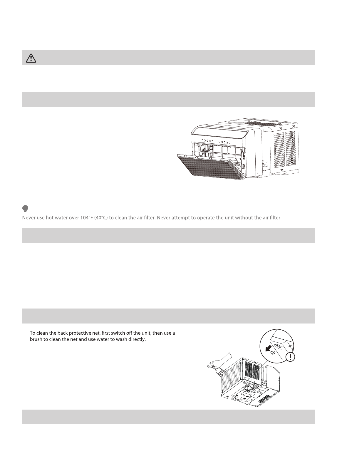
Air Filter Cleaning
Cabinet Cleaning
•
•
thoroughly.
•
•
Instead of washing, the filter may also be
vacuumed clean.
Grasp the filter by the center and pull up and out.
Wash the filter using warm water. Rinse filter
Gently shake excess water from the filter. Be sure
the filter is thoroughly dry before replacing.
The air filter should be checked at least once every
two weeks to see if cleaning is necessary. Trapped
particles in the filter can build up and reduce
performance by restricting airflow through the coils.
•
• Never use harsh cleansers, wax, or polish on the air conditioner.
Be sure to unplug the air conditioner to prevent shock or fire hazard. The cabinet and front may be
dusted with an oil-free cloth or washed with a cloth dampened in a solution of warm water and mild liquid
dishwashing detergent. Rinse thoroughly and wipe dry.
• Be sure to wring excess water from the cloth before wiping around the controls. Excess water in or around
the controls will cause damage to the air conditioner.
• Plug in air conditioner.
CAUTION
Clean the air conditioner occasionally to keep it looking new. Be sure to unplug the unit before cleaning to prevent shock or fire
hazards.
NOTE
Winter Storage
If storing the air conditioner for winter, remove it carefully from the window following the installation instructions. Avoid spilling any
standing water from the unit’s base pan; if water is present, drain it carefully. Cover the unit with plastic or place it back in the original
carton and store in a cool, dry place.
It is highly recommended to remove the water plug when washing the back
protective net, and then insert the water plug back into the original place
after draining to avoid mold or odor.
•
•
Back Protective Net Cleaning (On some models)
41

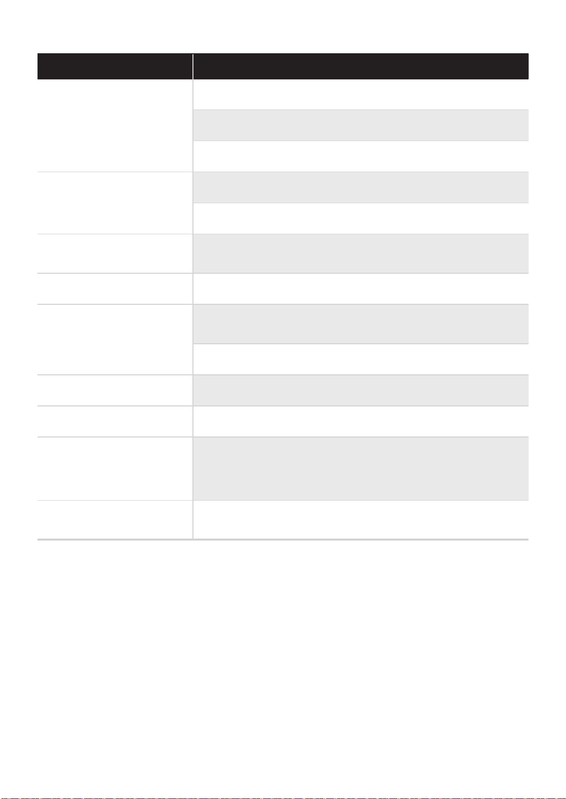
TROUBLESHOOTING TIPS
Problem Solution
Air conditioner does not start.
Wall plug disconnected. Push plug rmly into wall outlet.
Circuit breaker tripped. Reset circuit breaker.
Check if the light on the plug is on. If it is o, press the RESET button.
Power is OFF. Turn power ON.
Unit turned o and then on quickly. Turn unit o and wait 3 minutes
before restarting.
Air from unit does not feel cold
enough.
Room temperature below 6 F (1 C). Cooling may not occur until room
temperature rises above 6 F (1 C).
Temperature sensor behind the air lter is touching the cold coil. Try to
move it so it does not contact the cold coil.
Reset to a lower temperature.
Compressor shut-o by changing modes. Wait approximately 3 minutes
and listen for compressor to restart when set in the COOL mode.
Check for potential obstructions blocking the outdoor intake/exhaust.
Clear any obstructions.
Air conditioner cooling, but room
is too warm- ice forming on
cooling coil behind air lter.
Outdoor temperature below 64°F (18°C). To defrost the coil, set to FAN
ONLY mode.
Air lter may be dirty. Clean lter. Refer to Care and Cleaning section. To
defrost, set to FAN ONLY mode.
Thermostat set too cold for night-time cooling. To defrost the coil, set to
FAN ONLY mode. Then, set temperature to a higher setting.
Air conditioner cooling, but room
is too warm- NO ice forming on
cooling coil behind air lter.
Dirty or restricted air lter. Clean lter. Refer to Care and Cleaning section.
To defrost, set to FAN ONLY mode.
Temperature is set too high, set temperature to a lower setting.
Air directional louvers positioned improperly. Position louvers for better
air distribution.
Front of unit is blocked by drapes, blinds, furniture, etc. - restricts air
distribution. Clear obstruction in front of unit.
Any open doors, windows, or vents may allow cold air to escape. Close
any doors, windows, or vents.
The room may be too warm. Allow additional time to remove “stored
heat” from walls, ceiling, oor and furniture.
Before calling for service, review this list. It may save time and expense. This list includes common
0°
0°
6°
6°
occurrences that are not the result of defective workmanship or materials in this unit.
42
Problem Solution
Air conditioner turns on and o
rapidly.
Dirty air lter- air restricted. Clean air lter.
Outside temperature extremely hot. Set FAN speed to a higher setting to
bring air past cooling coils more frequently.
Check for potential obstructions blocking the outdoor intake/exhaust.
Clear any obstructions.
Noise when unit is cooling.
Air movement sound. This is normal. If too loud, set to a slower FAN
setting.
Window vibration - poor installation. Refer to installation instructions or
check with installer.
Water dripping INSIDE when unit
is cooling.
Improper installation. Tilt air conditioner slightly to the outside to allow water
drainage.
Refer to installation instructions - check with installer.
Water dripping OUTSIDE when
unit is cooling.
Unit removing large quantity of moisture from humid room. This is normal
during excessively humid days.
Remote sensing deactivating
prematurely (some models).
Remote control not located within range. Place remote control within
26 feet & 180°, radius of the front of the unit, and pointed in the general
direction of the air conditioner unit.
Remote control signal obstructed. Remove obstruction.
Noise when unit starts.
A 30 second high pitched noise may occur when the unit is turned on due
to the compressor starting. This is normal.
Window does not insert into the
U-shaped slot.
Ensure that the “U-shaped” slot is in line with the window, if not, align the
slot with the window.
Ensure that the unit is not slanted too much to cause interference with
the top of the unit. Reference the installation instructions for more
information.
Unit will not connect to WiFi
or App does not work (some
models).
For additional support and troubleshooting tips, visit the “Help” tab within
the SmartHome app.
Temperature setting too low. Increase temperature setting.
Room too cold.
43
logo, word marks, trade name, trade dress and all versions thereof are valu-
-
marks, copyrights and other intellectual property rights, and all goodwill derived from
using any part of a Midea trademark. Use of Midea trademark for commercial purposes
without the prior written consent of Midea may constitute trademark
infringement or unfair competition in violation of relevant laws.
This manual is created by Midea and Midea reserves all copyrights thereof. No entity or
individual may use, duplicate, modify, distribute in whole or in part this manual, or
bundle or sell with other products without the prior written consent of Midea.
All the described functions and instructions were up to date at the time of printing this
manual. However, the actual product may vary due to improved functions and designs.
TRADEMARKS, COPYRIGHTS
AND LEGAL STATEMENT
44
DATA PROTECTION NOTICE
For the provision of the services agreed with the customer,
we agree to comply without restriction with all stipulations of applicable data
protection law, in line with agreed countries within which services to the customer
will be delivered, as well as, where applicable, the EU General Data Protection
Regulation (GDPR).
for product safety reasons, to safeguard your rights in connection with warranty
and product registration questions. In some cases, but only if appropriate data
protection is ensured, personal data might be transferred to recipients located
outside of the European Economic Area.
Further information are provided on request. You can contact our Data Protection
[email protected]. To exercise your rights such as right to object
your personal date being processed for direct marketing purposes, please contact
us via [email protected]. To find further information, please follow the QR
Code.
The design and specifications are subject to change without prior notice for
product improvement. Consult with the sales agency or manufacturer for details.
Any updates to the manual will be uploaded to the service website, please check
for the latest version.
Generally, our data processing is to fulfill our obligation under contract with you and
45

WARRANTY
Air Conditioner Limited Warranty
Your product is protected by this Limited Warranty:
Warranty service must be obtained from Midea Consumer Services or an authorized Midea servicer.
Warranty
Midea, through its authorized servicers will:
Consumer will be responsible for:
• Diagnostics, removal, transportation and reinstallation cost required because of service.
• Costs of service calls that are a result of items listed under NORMAL RESPONSABILITIES OF THE CONSUMER**
Midea replacement parts shall be used and
will be warranted only for the original war
ranty.
This warranty applies only to products in ordinary household use, and the consumer is responsible for the
items listed below:
.
EX
CLUSIONS
This warranty does not cover the following:
1)
malfunction), by its improper installation, or by unreasonable use of the unit, including without limitation,
failure to provide reasonable and necessary maintenance or to follow the written installation and
Operating Instructions.
2) Damages caused by serviced performed by persons other than those authorized by Midea customer
service; or external causes such as abuse, misuse, inadequate power supply or acts of God.
3) If the unit is put to commercial, business, rental, or other use or application other than for consumer
use, we make no warranties, express or implied, including but not limited to, any implied warranty of
merchantability or tness for use or purpose.
4) Products without original serial numbers or products that have serial numbers which have been altered or
cannot be readily determined.
NOTICE: Some states do not allow the exclusions or limitation of incidental or consequential damages.
So this limitation or exclusion may not apply to you.
IF YOU NEED SERVICE
Service under this warranty must be obtained by following these steps, in order:
1) Contact Midea Consumer Services or an authorized Midea services at 1 866 646 4332.
2) If there is a question as to where to obtain service, contact our consumer relations Departament.
NORMAL RESPONSIBILITIES OF THE CONSUMER**
2. Routine maintenance and cleaning necessary to keep the good working condition.
4. Proper connection to a grouded power supply of su cient voltage, replacement of blown fuses, repair of loosen
connections or defects in house wiring.
6.
Failure caused by damage to the unit while in your possession (other than damage caused by defect or
Damages to finish after installation.
46
• One Year Limited Warranty from the date of delivery or the purchase date, whichever is later.
• Five Year Limited Sealed System Warranty (includes components containing refrigerant) from the date of
delivery or the purchase date, whichever is later.
• Three Year Limited Compressor Warranty from the date of delivery or the purchase date, whichever is later.
• The date of delivery establishes the warranty period, should service be required.
• Pay all costs for reparing or replacing parts of this unit which prove to be defective in materials or workmanship.
Keep the bill of sale, delivery slip, or some other appropriate payment record.
The date on the bill establishes the warranty period, should service be required.
If service is performed, its your best interest to obtain and keep all receipts.
This written warranty provides specific legal rights, and additional rights may vary by state.
1.
3. Proper installation by an authorized service professional in accordance with instructions provided with the
unit and in accordance with all local plumbing, electrical and/or gas codes.
5. Expenses for making the unit accessible for servicing.
Proper use of the unit in accordance with instructions provided with the product.


CW009UI-QB
2024
20241012
16120300A34192