
6a
(6x)
9s
9r
4b
6b
38
6a
4f
9j
11
4c
(15x)
4a
4d
4e
6c
9k
9m
9q
9p
9n
9c
(2x)
9d
(2x)
9e
(2x)
9f
(2x)
36
9g
(2x)
1c
(2x)
9h
(4x)
50
9r 9s
43
9k 9m
9n 9p
9q
42
9c 9d
9e 9f
9g
41
1c
39
4a 4b 4c 4d
4e 4f 6a 11
35
6a 6b
6c 9h
37
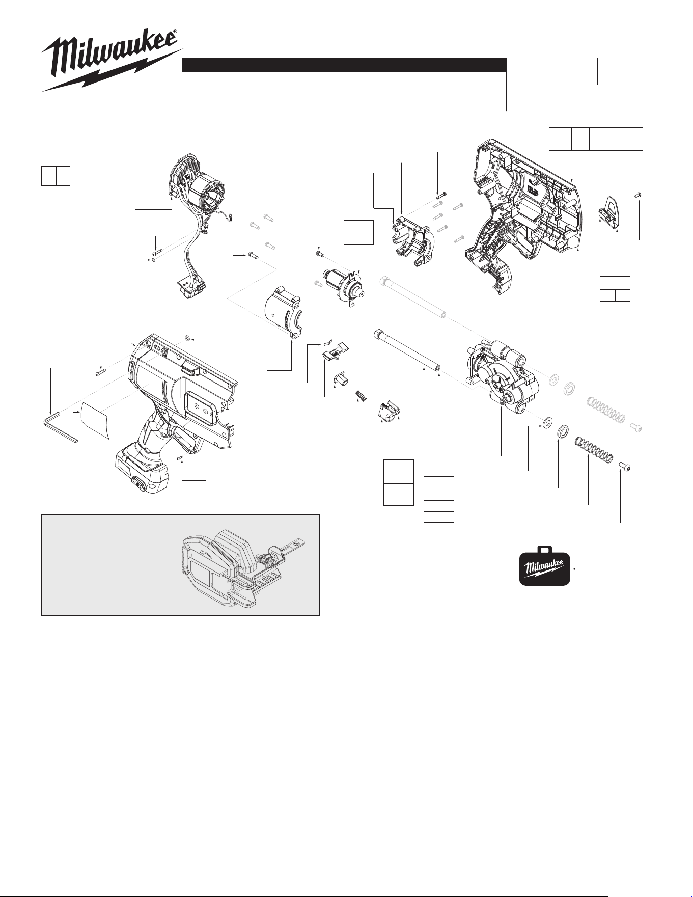
BULLETIN NO.
PN0005261
SERVICE PARTS LIST
CATALOG NO. 3469-20
REVISED BULLETIN
SPECIFY CATALOG NO. AND SERIAL NO. WHEN ORDERING PARTS
M18 FUEL™ 1/2" – 1" STEEL PIPE CUTTER
SERIAL NO.
DATE
May 2025
WIRING INSTRUCTION
R22A
See Page 4
MILWAUKEE TOOL
l
www.milwaukeetool.com
13135 W. LISBON RD., BROOKFIELD, WI 53005
Drwg. 1
FIG. SERVICE NOTES
11,12
A clean, dry surface is essential for proper performance for
any adhesive system. The area intended for application of any
adhesive label or nameplate must be prepared by cleaning with
isopropyl alcohol. The solvent is to be applied with a clean, lint
free applicator and the surface allowed to dry before applying
the label or nameplate.
FIG. PART NO. DESCRIPTION OF PART NO. REQ.
1c 05-78-0105 M4 x 10mm Pan Hd. Torx T-20 Screw (2)
4a --------------- Housing Cover (1)
4b --------------- Housing Support (1)
4c 05-88-0122 M3.5 x 16mm PH Self Tapping Screw (15)
4d 34-40-4480 O-Ring (1)
4e --------------- M2.3 x 9mm PH Torx T-8 B ST Screw (1)
4f --------------- O-Ring for Trigger Switch (1)
6a 06-82-6351 M3 x 16mm PH Torx T-10 B ST Screw (7)
6b --------------- Motor Housing Support (1)
6c --------------- Motor Housing Cover (1)
9c 05-81-0132 M6 x 14mm PH Torx T-30 M Screw (2)
9d --------------- Compression Spring (2)
9e --------------- Dust Cover (2)
9f --------------- Dust Felt (2)
9g --------------- Guide Pin (2)
9h 05-78-5316 M4 x 14mm Torx T-20 Taptite Screw (4)
9j 49-96-0600 3/16" Hex Key (1)
9k --------------- Spring Plate (1)
9m --------------- Forward & Reverse Shuttle (1)
9n --------------- Spring Housing Switch (1)
9p --------------- Trigger Spring (1)
9q --------------- Linear Trigger Cap (1)
9r 42-70-5151 Belt Hook (1)
9s 06-82-2500 #6-32 PH Torx T-15 & Slot M Screw (1)
11 12-20-3469 Service Nameplate (1)
35 31-50-3400 Housing Kit (1)
36 14-29-3400 Gearbox Assembly (1)
37 14-46-3402 Motor Housing Kit (1)
38 14-20-3401 Electronics Assembly (1)
39 16-01-3400 Rotor Assembly (1)
41 14-46-3404 Guide Pin & Spring Kit (1)
42 14-46-3403 Trigger Kit (1)
43 42-70-0950 Belt Clip Kit (1)
50 42-55-0081 BMC - Blow Molded Case (1)
FIG. PART NO. DESCRIPTION OF PART NO. REQ.
0
00
EXAMPLE:
Component Parts (Small #)
Are Included When Ordering
The Assembly (Large #).
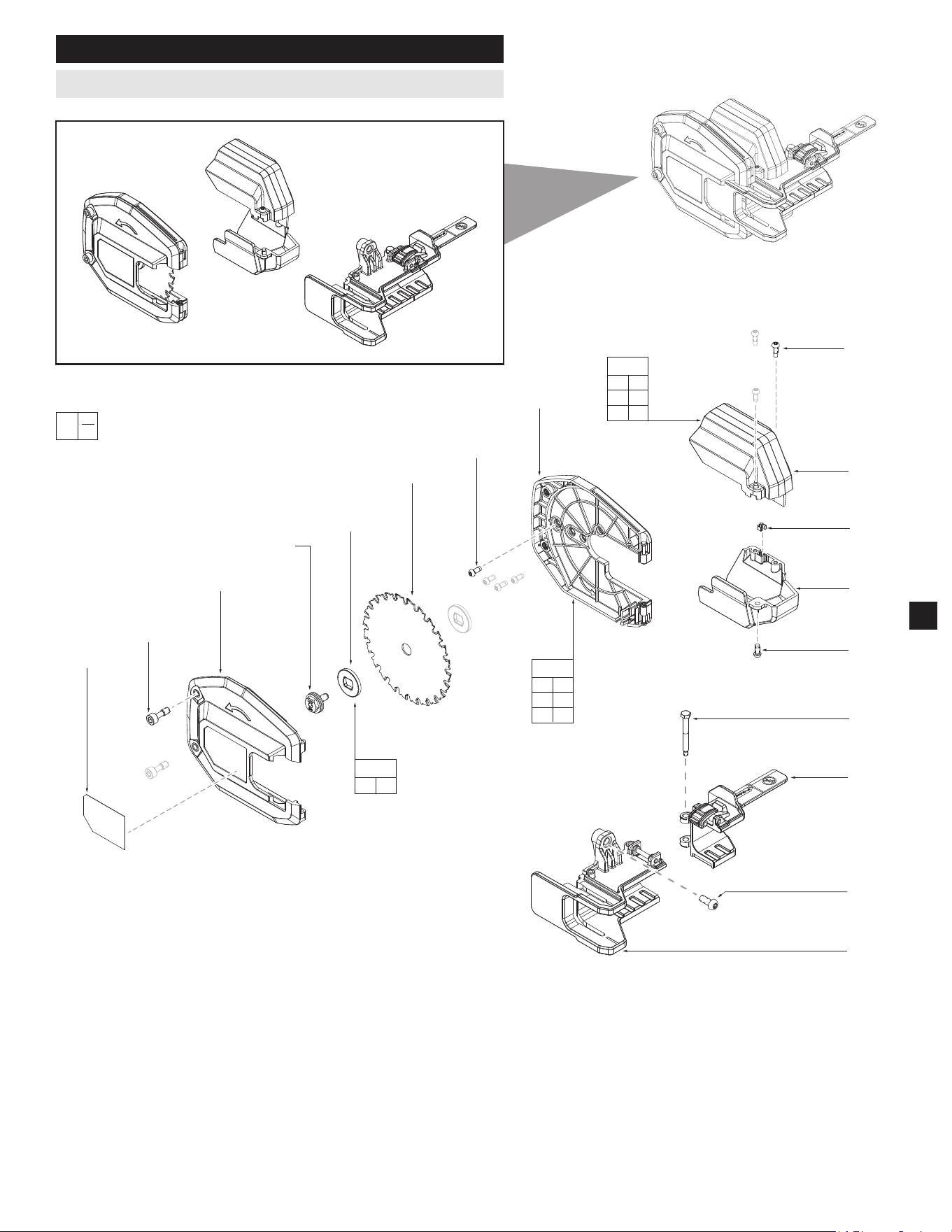
PLUNGE PLATE,
SHIELD COVER,
SIDE PLATE &
GUARD
- See page 2
12
1a
(2x)
1b
9a
9b
(2x)
15
1c
(4x)
1d
2d
(2x)
2b
2c
2a
1c
(2x)
3c
33
9c
34
1a 1b
1c 1d
12
31
1c 2a
2b 2c
2d
32
9a 9b
40
FIG. PART NO. DESCRIPTION OF PART NO. REQ.
1a --------------- Guard Screw (2)
1b --------------- Blade Guard (Right) (1)
1c 05-78-0105 M4 x 10mm PH T-20 Taptite Screw (6)
1d --------------- Blade Guard (Left) (1)
2a --------------- Bottom Shield Cover (1)
2b --------------- Top Shield Cover (1)
2c 44-60-5335 Detent, Side Grip (1)
2d --------------- M4 x 12mm PH T-20 ST Screw (2)
3c 44-60-3400 Folding Handle Slide Pin (1)
9a --------------- M6 x SEMS Screw with Disc Spring (1)
SERVICE BILL OF MATERIAL (BOM) LISTING - Cont'd
EXAMPLE:
Component Parts (Small #)
Are Included When Ordering
The Assembly (Large #).
0
00
2
9b --------------- Inner Flange (2)
9c 05-81-0132 M6 x 14mm PH Torx T-30 M Screw (1)
12 10-22-3400 Warning Label (1)
15 48-40-4062 Blade (1)
31 14-32-0365 Guard Assembly (1)
32 14-46-3406 Shield Cover Kit (1)
33 43-56-3400 Side Grip Assembly (1)
34 44-70-3400 Plunge Plate Assembly (1)
40 14-46-3401 Blade Flange Kit (1)
FIG. PART NO. DESCRIPTION OF PART NO. REQ.
Guard • Shield Cover • Plunge Plate & Side Grip
1
2
3
4
5
6
7
8
9
10
11
12
13
14
15
16
1
2
3
4
5
6
7
3
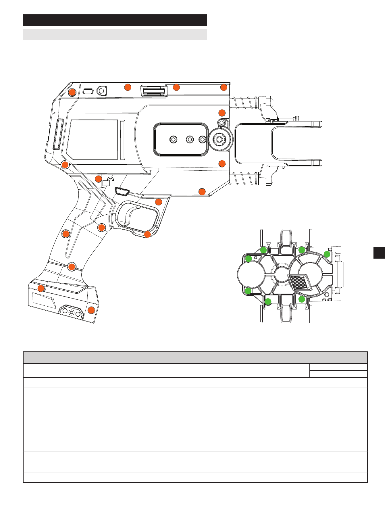
SCREW FASTENING ORDER
SEAT TORQUE
FIG. PART NO. DESCRIPTION OF FASTENER QTY WHERE USED (kgf-cm) (lb-in)
1a --------------- Guard Screw w/ THD. M6x1.0 Hex 2 Blade Guard (Right) 30 ± 3 26 ± 2.6
1c 05-78-0105 M4 x 10mm PH T-20 Taptite Screw 4 Blade Guard (Left) 23 ± 3 20 ± 2.6
2 Bearing Retainer 23 ± 3 20 ± 2.6
2 Shield Cover 19 ± 2 16.5 ± 1.7
2d --------------- M4 x 12mm PH T-20 ST Screw 2 Shield Cover 16 ± 2 13.8 ± 1.7
3c 44-60-3400 Folding Handle Slide Pin 1 Plunge Plate 15 ± 2 13 ± 1.7
4c 06-82-2025 M3.5 x 16mm PH Self Tapping Screw 15 Housing Cover 12 ± 2 17 ± 1.7
4e --------------- M2.3 x 9mm PH Torx T-8 B ST Screw 1 Housing Cover 3.5 ± 0.5 3 ± 0.4
6a --------------- M3 x 16mm PH Torx T-10 B ST Screw 6 Motor Housing Support 10 ± 2 8.6 ± 1.7
1 PCBA Electronics 4 ± 0.5 3.5 ± 0.4
9a --------------- M6 x SEMS Screw with Disc Spring 1 Inner Flange 60 ± 5 52 ± 4.3
9c 05-81-0132 M6 x 14mm PH Torx T-30 M Screw 2 Plunge Plate 85 ± 8 74 ± 6.9
9h 05-78-5316 M4 x 14mm Torx T-20 Taptite Screw 4 Motor Housing Cover 19 ± 2 16.5 ± 1.7
9s --------------- #6-32 PH Torx T-15 & Slot M Screw 1 Belt Hook 16 ± 2 13.8 ± 1.7
SCREW TORQUE SPECIFICATIONS
Handle Housing • Gearcase
Please follow the screw sequence below
when tightening and loosening the screws.
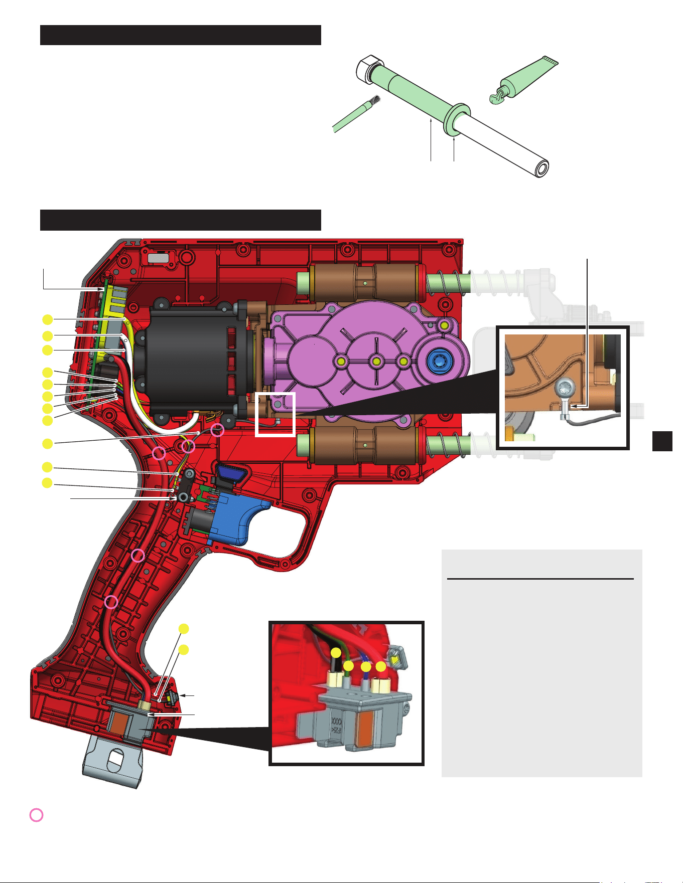
Use a brush to paint 0.2 ±0.1 g
of Grease on the half of the
Guide Pin (#9g) as shown.
Apply 0.5±0.2 g
of Grease on the
Dust Felt (#9f)
9g
9f
WIRE TRAPS
are designated
by pink circle
8
9
10
11
12
13
14
15
16
1
2
5
6
17
7
3
4
Terminal Block
Control
Board
LED Lens
Switch
Ground
Terminal
LUBRICATION INSTRUCTIONS
►
Type "J" Grease
No. 49-08-4220, 1 lb can
Apply thin coat of grease to areas indicated.
NOTE: When servicing, remove 90-95% of
the existing grease prior to installing Type "J".
Original grease may be similar in color but
not compatible with "J".
4
WIRING INSTRUCTIONS
FIG DESTINATION WIRE
# DESIGNATOR COLOR
1 Switch to Control Board Black
2 Switch to Control Board Yellow
3 LED to Control Board Red
4 LED to Control Board White
5 Hall Board to Control Board Yellow
6 Hall Board to Control Board Green
7 Hall Board to Control Board Blue
8 Hall Board to Control Board Black
9 Hall Board to Control Board Red
10 Stator to Control Board Yellow
11 Stator to Control Board White
12 Stator to Control Board Blue
13 Terminal to Control Board Black
14 Terminal to Control Board Green
15 Terminal to Control Board Blue
16 Terminal to Control Board Red
17 Terminal to Gearcase Left Black
WARNING
• Take notice of wire routing and position in wire guides and traps while dismantling tool.
• Besurethatallcomponentsoftheelectronicskitareseatedrmlyandsquarelyinhousingrecesses.
• Avoid pinched wires, be sure all wires and sleeves are pressed completely down in wire guides and traps.
• Prior to installing housing cover onto handle support, be sure that there are no interferences.
• Be sure to check for C functionality of switches and buttons after housing halves have been secured.