TEC_TM_157 REV. B
08/22/2022
ADA HEIGHT 15" TRUE ICE
®
MACHINE INSTALL GUIDE
*829074*
PRESERVE THE MOMENT
®
ADA HEIGHT
15 INCH TRUE ICE
®
MACHINE
INSTALL GUIDE AND USER'S MANUAL
TRUE RESIDENTIAL
®

TRUE RESIDENTIAL
®
P#829074 TEC_TM_157 REV. B EN08/22/2022Page 2 of 80
THANK YOU
FOR YOUR PURCHASE
ADA HEIGHT 15" TRUE ICE
®
MACHINE INSTALL GUIDETEC_TM_157 REV. B EN
08/22/2022
Page 3 of 80
PRESERVE THE MOMENT
®
LUXURY REFRIGERATION WITH COMMERCIAL DNA

TRUE RESIDENTIAL
®
P#829074 TEC_TM_157 REV. B EN08/22/2022Page 4 of 80
CONTENTS
INSTALLATION CHECKLIST 6
15 INCH TRUE ICE
®
MACHINE MODELS 7
SAFETY INFORMATION & OWNERSHIP
FEATURES OF THE TRUE ICE
®
MACHINE 10
OWNERSHIP 11
REFRIGERANT SAFETY & WARNING
INFORMATION 11
SAFETY LABELS & LOCATIONS 12
BASIC SAFETY & WARNING PRECAUTIONS 14
PROPER DISPOSAL OF THE CABINET 14
CABINET LOCATION & SPECIFICATIONS 15
CONTACT US 15
OUTDOOR USE 15
PRIOR TO INSTALLATION
ADA-COMPLIANT INSTALLATION ROUGH
OPENING & PLAN VIEWS [32" (813 MM)
OPENING] 18
OPTIONAL INSTALLATION ROUGH
OPENING & PLAN VIEWS [34-1/2"
(877 MM) OPENING] 21
CUSTOM OVERLAY PANEL
SPECIFICATIONS 26
ELECTRICAL INSTALLATION & SAFETY 34
PLUMBING REQUIREMENTS &
INSTALLATION 36
INSTALLATION
UNCRATING 44
LEVELING LEGS 45
LEVELING 46
KICKPLATE INSTALLATION 46
CABINET SETUP
ICE SCOOP 48
90˚DOORSTOP INSTALLATION
(OPTIONAL ACCESSORY) 48

ADA HEIGHT 15" TRUE ICE
®
MACHINE INSTALL GUIDETEC_TM_157 REV. B EN
08/22/2022
Page 5 of 80
CONTENTS
CABINET OPERATION
BEFORE OPERATING 50
BREAKER RESET 50
POWER SEQUENCE 50
ICE MAKING SEQUENCE 51
ELECTRONIC CONTROL OPERATION 52
MAINTENANCE, CARE, & CLEANING
GENERAL MAINTENANCE 60
WATER FILTER REPLACEMENT 61
CONDENSER COIL CLEANING 62
STAINLESS STEEL EQUIPMENT
CARE & CLEANING 64
DESCALING & SANITIZING 66
INTERIOR COMPONENTS 68
WINTERIZING 71
SERVICING, REPLACING
COMPONENTS & ADJUSTMENTS
SERVICING & REPLACING COMPONENTS 74
REVERSING DOOR 74
DOOR ADJUSTMENT 77
CONTACT US 77
WARRANTY
ADA WARRANTY STATEMENT 79

TRUE RESIDENTIAL
®
P#829074 TEC_TM_157 REV. B EN08/22/2022Page 6 of 80
INSTALLATION CHECKLIST
To ensure no part of the installation process has been overlooked, complete the checklist below.
Has an authorized True dealer or licensed installer inspected stainless steel surfaces
for imperfection?
(Cosmetic defects are covered by a limited 30-day warranty)
Have all packaging materials been removed?
Is the unit properly leveled with all leveling legs contacting the floor?
Has the water filter been installed? Has the water supply been turned on?
Have the water supply and drain connections been made?
Is the water supply temperature always between 40-100˚F (4.4-7.8˚C)?
Has the ice machine drain line been routed into an open drain with no more than 84"
(2,133.36 mm) vertical rise for 3/8" O.D. tubing and no more than 100’ (30.48 m) run?
Has the water supply been turned on?
Is the power cord plugged into a properly grounded three-prong outlet in accordance with all
applicable electrical codes?
Have all connections been checked for water leaks? If not, pour water directly into the ice
storage bin to ensure drain pump operation and inspect for leaks.
Were the ice maker and storage bin disinfected prior to use? If not, see “Sanitizing" (page 67).
Has the ice machine been turned on? During the initial fill, can you hear the water valve turn
on and see water filling the reservoir tank?
After the first ice cycle, did all 24 ice cubes fall into the bin during harvest?
Have the first two batches of ice been discarded?
Has the customer reviewed the unit’s operation in this manual?
Has the customer reviewed the schedule of maintenance of the machine?
ADA HEIGHT 15" TRUE ICE
®
MACHINE INSTALL GUIDETEC_TM_157 REV. B EN
08/22/2022
Page 7 of 80
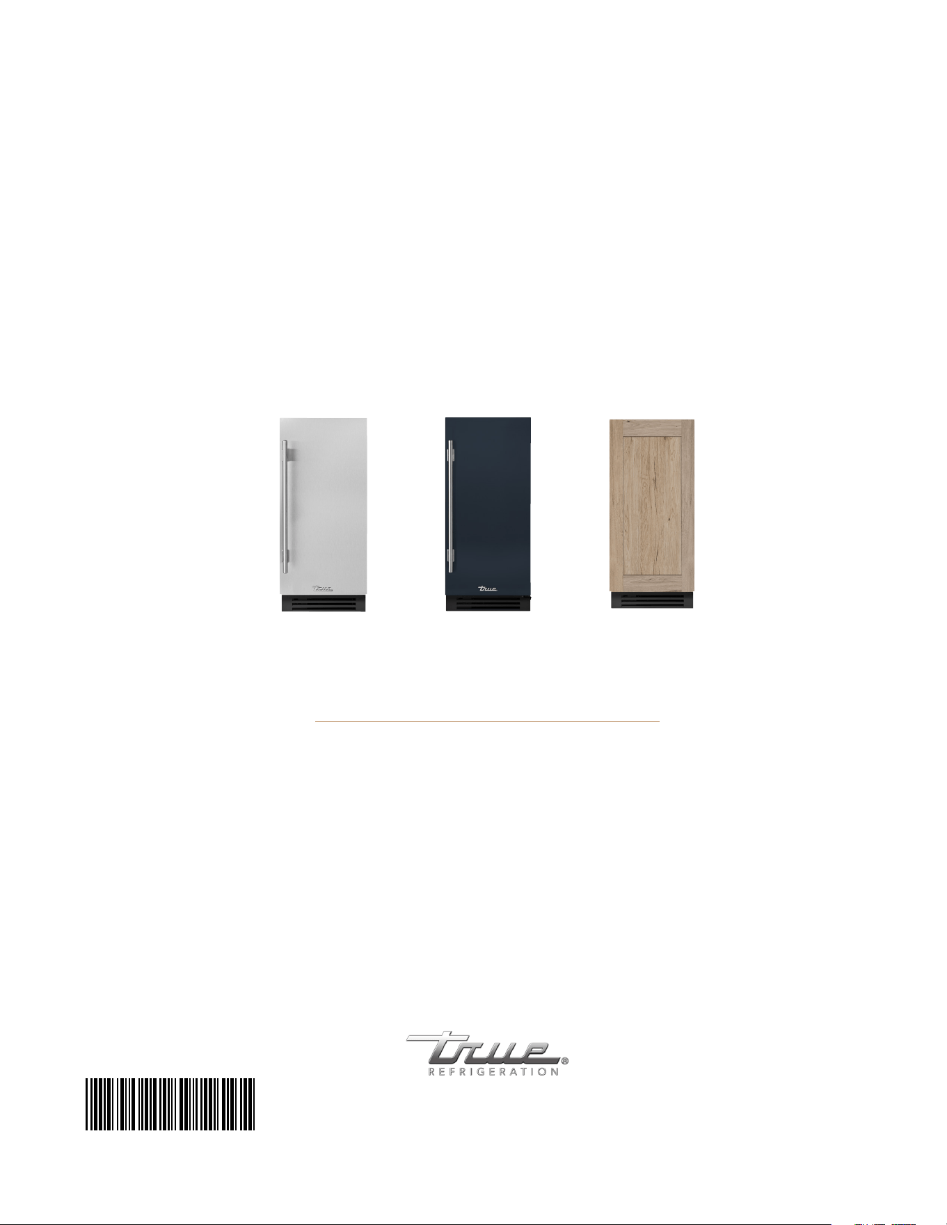
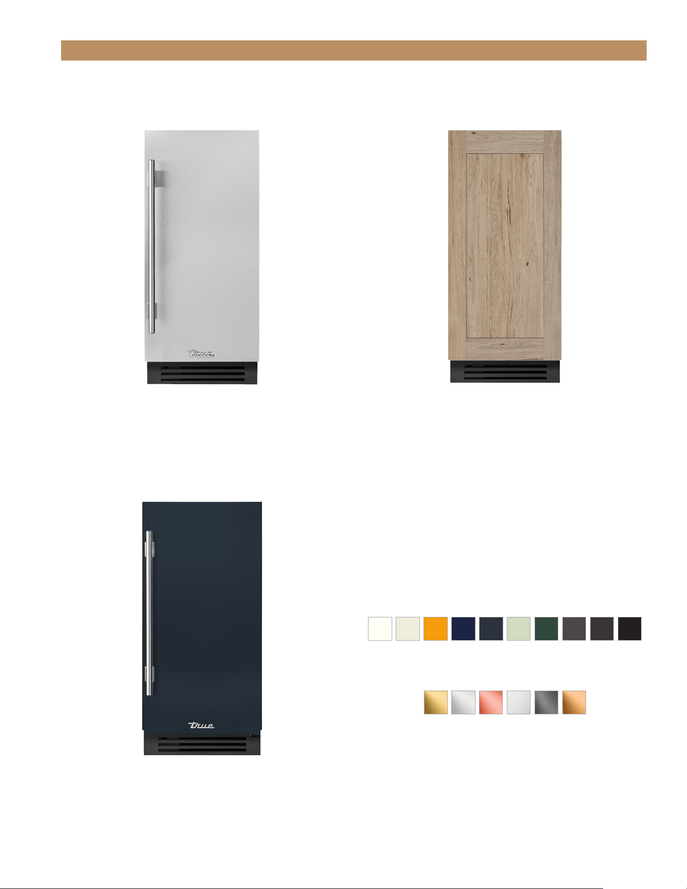
15 INCH TRUE ICE
®
MACHINE MODELS
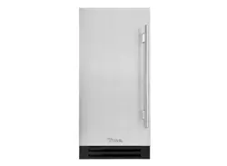
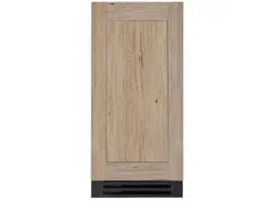
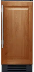
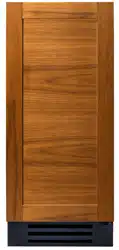
FINISHES
15" STAINLESS STEEL 15" OVERLAY PANEL
15" CUSTOM FINISH
HARDWARE
TUIADA-15-RS/LS-A~S TUIADA-15-RS/LS-A~O
TUIADA-15-RS-A~104-H04
CUSTOMIZE YOUR TRUE WITH
A VARIETY OF FINISH AND
HARDWARE OPTIONS AT
https://true-residential.com/custom/

TRUE RESIDENTIAL
®
P#829074 TEC_TM_157 REV. B EN08/22/2022Page 8 of 80
NOTES

ADA HEIGHT 15" TRUE ICE
®
MACHINE INSTALL GUIDETEC_TM_157 REV. B EN
08/22/2022
Page 9 of 80
FEATURES OF THE TRUE ICE
®
MACHINE
OWNERSHIP
REFRIGERANT SAFETY & WARNING INFORMATION
SAFETY LABELS & LOCATIONS
BASIC SAFETY PRECAUTIONS & WARNINGS
PROPER DISPOSAL OF THE CABINET
CABINET LOCATION & SPECIFICATIONS
CONTACT US
OUTDOOR USE
SAFETY INFORMATION & OWNERSHIP
PRESERVE THE MOMENT
®
TRUE RESIDENTIAL
®
P#829074 TEC_TM_157 REV. B EN08/22/2022Page 10 of 80
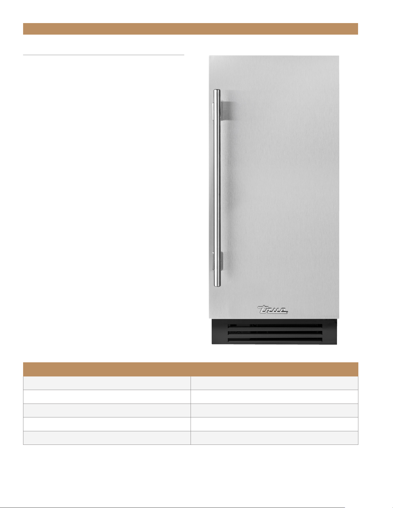
SAFETY INFORMATION & OWNERSHIP
FEATURES OF THE TRUE ICE MACHINE
• Articulating, soft close hinge allows fully integrated,
flexible installations.
• Produces up to 75lb (34kg) of clear ice per day
with a storage capacity of 28lb (12.7kg).
• Bin Level Control for entertaining flexibility
(50%, 65%, 70%, 85%, 100%).
• Patented TruLumina
®
LED lighting gently illuminates
your product and allows you to choose from 14
different color options with the push of a button.
• Concealed digital control located behind toekick.
• Exclusive True Magna Scoop for easy storage
on door.
• Industry exclusive, standard built-in drain pump.
• External water filter kit included – rated up to
1250 gallons.
• Automatic cleaning system.
• All undercounter models UL rated for outdoor use.
• Environmentally friendly R290 refrigerant.
• Energy Star rated.
• Industry-leading True Warranty.
PERFORMANCE SPECIFICATIONS
*Maximum Ice Capacity (lbs/day)
75lb (34kg) / day
**Rated Ice Capacity (lbs/day)
75lb (34kg) / day
**Rated Ice Storage (lbs)
28lb (12.7kg)
**Rated Energy Consumption (kWh/lbs)
6.65 kwH / 100 lbs
**Rated Water Consumption (Gal/lbs)
24.2 Gal / 100 lbs
*Performance rated at 70˚F (21.1˚C) air / 50˚F (10˚C) water / 30 psig (206.8 kPa) water pressure
**Performance rated at 90˚F (32.2˚C) air / 70˚F (21.1˚C) water / 30 psig (206.8 kPa) water pressure
ADA HEIGHT 15" TRUE ICE
®
MACHINE INSTALL GUIDETEC_TM_157 REV. B EN
08/22/2022
Page 11 of 80
SAFETY INFORMATION & OWNERSHIP
OWNERSHIP
To ensure that your unit works properly from the
first day, it must be installed properly. We highly
recommend a trained refrigeration mechanic and
electrician install your True equipment. The cost of a
professional installation is money well spent.
Before you start to install your TRUE unit, carefully
inspect it for freight damage. IF DAMAGE IS
DISCOVERED, DO NOT INSTALL THE UNIT OR PUT
IT IN SERVICE. Notify True customer service, and
immediately file a claim with the delivery freight carrier.
TRUE is not responsible for damage incurred during
shipment.
For any questions about installation, please contact
your True dealer or True Residential Technical Service
at 844-746-9423 or TrueResidentialService@TrueMfg.
com. Please have your model and serial number
available.
WARNING! PROPER INSTALLATION
REQUIRES A CONNECTION TO
THE WATER SUPPLY, A DRAIN,
AND A DEDICATED ELECTRICAL
CIRCUIT. THESE CONNECTIONS ARE THE
RESPONSIBILITIES OF THE INSTALLER.
IMPROPER CONNECTIONS CAN RESULT IN
PERSONAL INJURY, PROPERTY DAMAGE AND
IMPROPER OPERATION. THE ICE MACHINE
MUST BE INSTALLED ACCORDING TO ALL
APPLICABLE NATIONAL, STATE AND LOCAL
CODES AND REGULATIONS.
REFRIGERANT SAFETY & WARNING
INFORMATION
This unit contains hydrocarbon refrigerant (R-290).
Please carefully and completely read all
safety labels and the warnings below:
DANGER! Risk of fire or explosion.
Flammable refrigerant used. DO NOT use
mechanical devices to defrost refrigerator.
DO NOT puncture refrigerant tubing;
follow handling instructions carefully. To
be repaired only by trained service personnel.
DANGER! Risk of fire or explosion
(flammable refrigerant used), consult
repair manual/owner’s guide before
attempting to service this product. All
safety precautions must be followed.
Dispose of properly in accordance with
local and federal regulations. Follow all
safety precautions.
CAUTION! Keep all ventilation openings
clear of obstruction in the appliance
enclosure or in the structure housing the
appliance.
INFORMATIONS DE SÉCURITÉ ET
D’AVERTISSEMENT CONCERNANT LE
FRIGORIGÈNE
Consultez l’étiquette de numéro de série à l’intérieur
de l’armoire pour connaître le type de réfrigération des
appareils. Pour une réfrigération aux hydricarbures
seulement (R290), voir ci-dessous
DANGER! Risque de feu ou d’explosion. Le
frigorigène utilisé est inflammable.
Ne PAS! utiliser des appareils mécaniques
pour dégivrer le réfrigérateur.
Ne PAS! percer les tuyaux de réfrigérant;
suivre scrupuleusement les instructions
de manutention. Les réparations doivent
être effectuées seulement par à un
technicien qualifié.
DANGER! Risque d’incendie ou d’explosion
(réfrigérant inflammable utilisé), consultez
le manuel de réparation/guide d’utilisation
avant toute tentative d’intervention
sur ce produit. Toutes les mesures de
sécurité doivent être respectées. Mettez
au rebut conformément aux règlements
fédéraux ou locaux. Respectez toutes les
précautions de sécurité.
ATTENTION! Éviter toute obstruction des
ouvertures de ventilation dans la pièce où
l’armoire est située ou sur l’armoire elle-
même.
TRUE RESIDENTIAL
®
P#829074 TEC_TM_157 REV. B EN08/22/2022Page 12 of 80
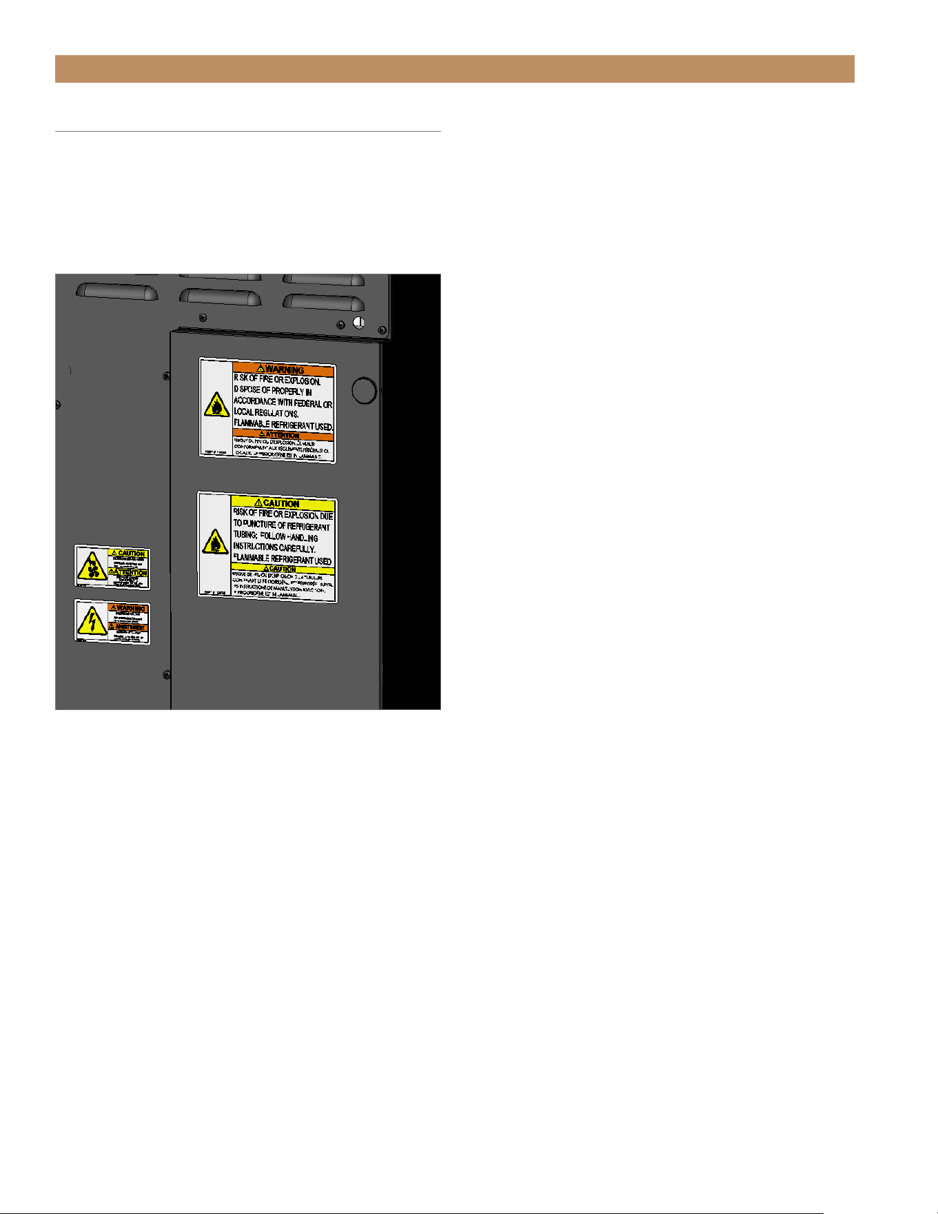
SAFETY INFORMATION & OWNERSHIP
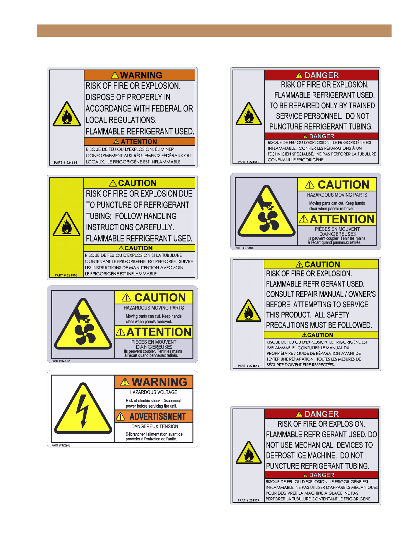
SAFETY LABELS & LOCATIONS
Your new ice maker has labels placed in specific
locations throughout the cabinet which identify
important safety information. Please take a moment
to familiarize yourself with the content and label
locations.
FIG. 1.
Example of safety label locations. Not all labels or locations shown.
ADA HEIGHT 15" TRUE ICE
®
MACHINE INSTALL GUIDETEC_TM_157 REV. B EN
08/22/2022
Page 13 of 80
SAFETY INFORMATION & OWNERSHIP
INSIDE THE COMPRESSOR COMPARTMENTON THE REAR PANEL
BENEATH THE EVAPORATOR COVER’S TOP PANEL
TRUE RESIDENTIAL
®
P#829074 TEC_TM_157 REV. B EN08/22/2022Page 14 of 80
BASIC SAFETY & WARNING
PRECAUTIONS
• Take care during operation, maintenance or repairs
to avoid cuts or pinching from any part/component
of the cabinet.
• Units may pose a tipping hazard while uncrating,
during installation, or when moving the unit.
• Ensure the unit is properly installed and located in
accordance with the Installation Instructions before
use.
• This appliance is not to be used, cleaned or
maintained by persons (including children) with
reduced physical, sensory or mental capabilities or
lack of experience and knowledge, unless they have
been given supervision or instruction.
• DO NOT allow children to play with the appliance
or climb, stand, or hang on the unit’s shelves to
prevent damage to the refrigerator and personal
injury.
• DO NOT touch the cold surfaces in the freezer
compartment when hands are damp or wet. Skin
may stick to these extremely cold surfaces.
• Unplug the ice maker before cleaning and making
repairs.
• Powering off the ice maker will not remove power
from all components (e.g., light circuit and drain
pump).
• DO NOT store or use gasoline, or other flammable
vapors and liquids, in the vicinity of this or any
other appliance.
• DO NOT store explosive substances such as aerosol
cans with a flammable propellant in this appliance.
• Keep fingers out of the "pinch point" areas;
clearances between the doors and cabinet are
necessarily small; be careful closing doors when
children are in the area.
• DO NOT use electrical appliances inside the food
storage compartments of the units unless the
appliances are of the type recommended by the
manufacturer.
NOTE: ALL SERVICING MUST BE
PERFORMED BY A QUALIFIED TECHNICIAN.
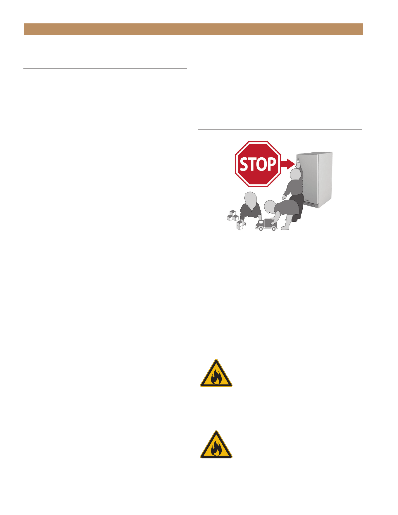
PROPER DISPOSAL OF THE CABINET
DANGER! RISK OF CHILD
ENTRAPMENT
Child entrapment and suffocation are not problems
of the past. Junked or abandoned appliances are still
dangerous, even if they will sit for "just a few days." If
you are getting rid of your old appliance, please follow
the instructions below to help prevent accidents.
Before throwing away your old ice machine:
Take off the door.
DANGER – Risk of fire or explosion.
Flammable insulation and/or refrigerant
used. Dispose of all in accordance with
local and federal regulations. Follow all
safety precautions.
DANGER – Risque de feu ou d’explosion.
Isolation et/ou réfrigérant inflammable
utilisé. Toujours mettre au rebut
conformément aux règlements fédéraux
ou locaux. Respectez toutes les
précautions de sécurité.
SAFETY INFORMATION & OWNERSHIP
ADA HEIGHT 15" TRUE ICE
®
MACHINE INSTALL GUIDETEC_TM_157 REV. B EN
08/22/2022
Page 15 of 80
CABINET LOCATION &
SPECIFICATIONS
For more information regarding the installation
location or cabinet specifications, please see “Prior to
Installation" starting on page 17.
• Appliance is Certified to NSF Standard 12.
• Appliance is UL rated for outdoor use.
• Appliance is not suitable for an area where a
pressure washer or hose may be used.
• Ensure the location will provide adequate
clearances and sufficient airflow for the cabinet.
• Ensure the power supply for the cabinet matches
the cabinet specification sheet or cabinet data plate
and is within the rated voltage (±5%) Also, ensure
the amperage rating of the circuit is correct and the
circuit is properly grounded.
• The cabinet should always be plugged into its own
individual dedicated electrical circuit. The use of
adapter plugs and extension cords is prohibited.
CONTACT US
For any questions about installation, please contact
your TRUE dealer or TRUE Residential Technical
Service. Please have your model and serial number
(see serial label location below) available so we can
better assist you with your service- or parts-related
inquiries.
Customer Service
Phone: 888-616-8783
info@true-residential.com
Warranty Department
Phone: 844-849-6179
TrueResidentialWarranty@truemfg.com
Technical Service Department
Phone: 844-746-9423
TrueResidentialService@truemfg.com
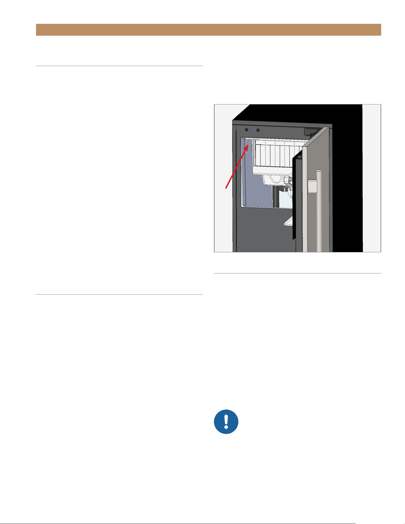
SERIAL LABEL LOCATION
Your serial label contains important information such
as your model and serial number. The label is located
on the upper left interior wall.
OUTDOOR USE
All True undercounter ice machines are rated for
outdoor use.
• The unit must be covered or otherwise protected
from direct exposure to rain.
• For the safest possible outdoor installation, build
the unit into an undercounter kitchenette area
within stone, brick, wood, etc.
• If the unit is expected to be exposed to low air
temperatures for a prolonged period of time,
please turn the unit off and winterize the unit.
See “Winterizing" (page 71).
NOTICE! DO NOT ALLOW THE ICE
MACHINE TO BE EXPOSED TO
TEMPERATURES BELOW 32˚F (0˚C)
WITHOUT WINTERIZING THE UNIT
AS THIS WILL CAUSE ANY WATER IN THE
MACHINE TO FREEZE. FAILURES CAUSED BY
EXPOSURE TO FREEZING TEMPERATURES ARE
NOT COVERED BY THE WARRANTY.
SAFETY INFORMATION & OWNERSHIP

TRUE RESIDENTIAL
®
P#829074 TEC_TM_157 REV. B EN08/22/2022Page 16 of 80
NOTES

ADA HEIGHT 15" TRUE ICE
®
MACHINE INSTALL GUIDETEC_TM_157 REV. B EN
08/22/2022
Page 17 of 80
PRIOR TO INSTALLATION
ADA-COMPLIANT INSTALLATION ROUGH OPENING & PLAN VIEWS
[32" (813 MM) OPENING]
OPTIONAL INSTALLATION ROUGH OPENING & PLAN VIEWS
[34-1/2" (877 MM) OPENING]
CUSTOM OVERLAY PANEL SPECIFICATIONS
CUSTOM OVERLAY PANEL INSTALLATION
ELECTRICAL SAFETY & INSTALLATION
PRESERVE THE MOMENT
®
TRUE RESIDENTIAL
®
P#829074 TEC_TM_157 REV. B EN08/22/2022Page 18 of 80
PRIOR TO INSTALLATION
ALLOWABLE AIR TEMPERATURES
Air Temperature Water Temperature Water Pressure
Minimum 40˚F (4.4˚C) 40˚F (4.4˚C) 20 psig (1.4 bar)
Maximum 100˚F (37.8˚C) 100˚F (37.8˚C) 80 psig (5.5 bar)
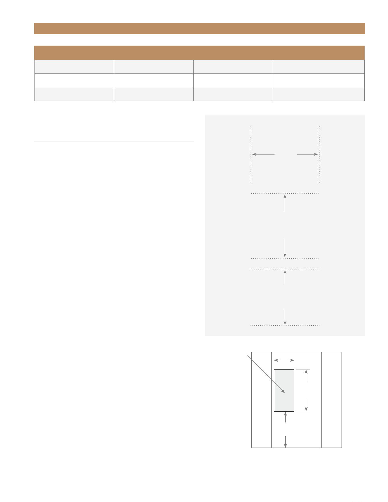
Avoid running
wires or
plumbing in this
area.
SURROUNDING CABINETRY
SURROUNDING CABINETRY
9"
(228.6 mm)
16"
(406.4 mm)
9
11/16
"
(233.1 mm)
FRONT VIEW OF CABINETRY OPENING
ANTI-SWEAT FOAM END PANELS
When installing two or more True units side-by-side,
be sure to leave at least a 5/8" (15.88 mm) gap
between the cabinets, or install foam pads between
the cabinets and on any side without this gap, to
prevent moisture from developing on applications.
If installing anti-sweat foam end panels, True
recommends applying a panel to each of the
units being joined together. To order foam pads,
contact our parts department at 844-849-6226 or
TrueResidentialParts@TrueMfg.com.
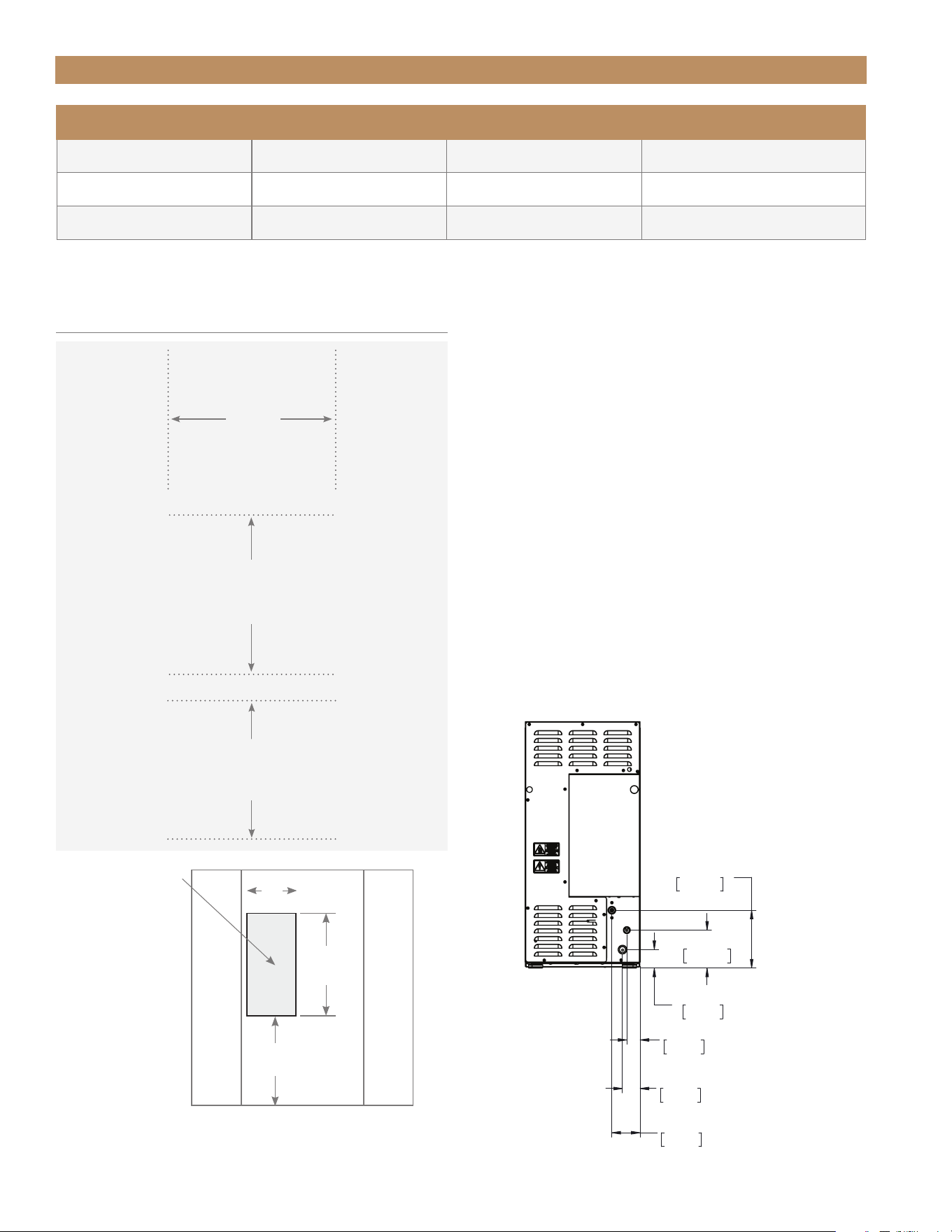
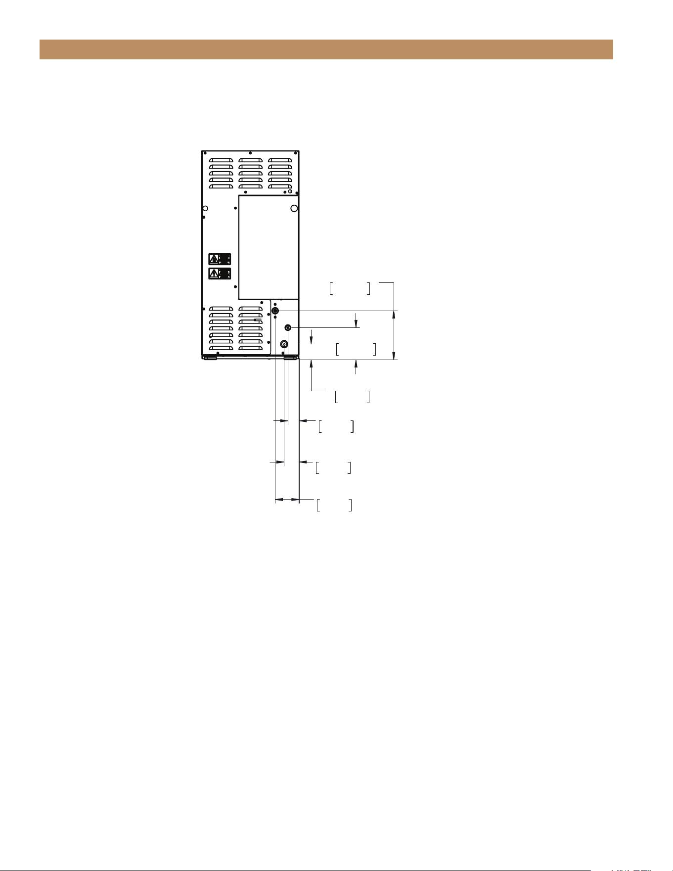
WATER LINE, DRAIN LINE, AND POWER CORD
LOCATIONS
The ice maker must be installed with adequate
clearance for water and drain connections at the rear
of the unit. For plumbing specifications, please see
“Plumbing Requirements & Installation” (page 36).
ROUGH
OPENING
HEIGHT
32" min
(813 mm)
ROUGH
OPENING
WIDTH
15" min
(381 mm)
ROUGH
OPENING
DEPTH
24" min
(609 mm)
ADA-COMPLIANT INSTALLATION
ROUGH OPENING & PLAN VIEWS
[32" (813 MM) OPENING]
7 15/32"
190mm
4 29/32"
125mm
2 3/8"
61mm
1 23/32"
44mm
POWER CORD
2 9/32"
58mm
WATER LINE
3 21/32"
93mm
DRAIN LINE
ADA HEIGHT 15" TRUE ICE
®
MACHINE INSTALL GUIDETEC_TM_157 REV. B EN
08/22/2022
Page 19 of 80
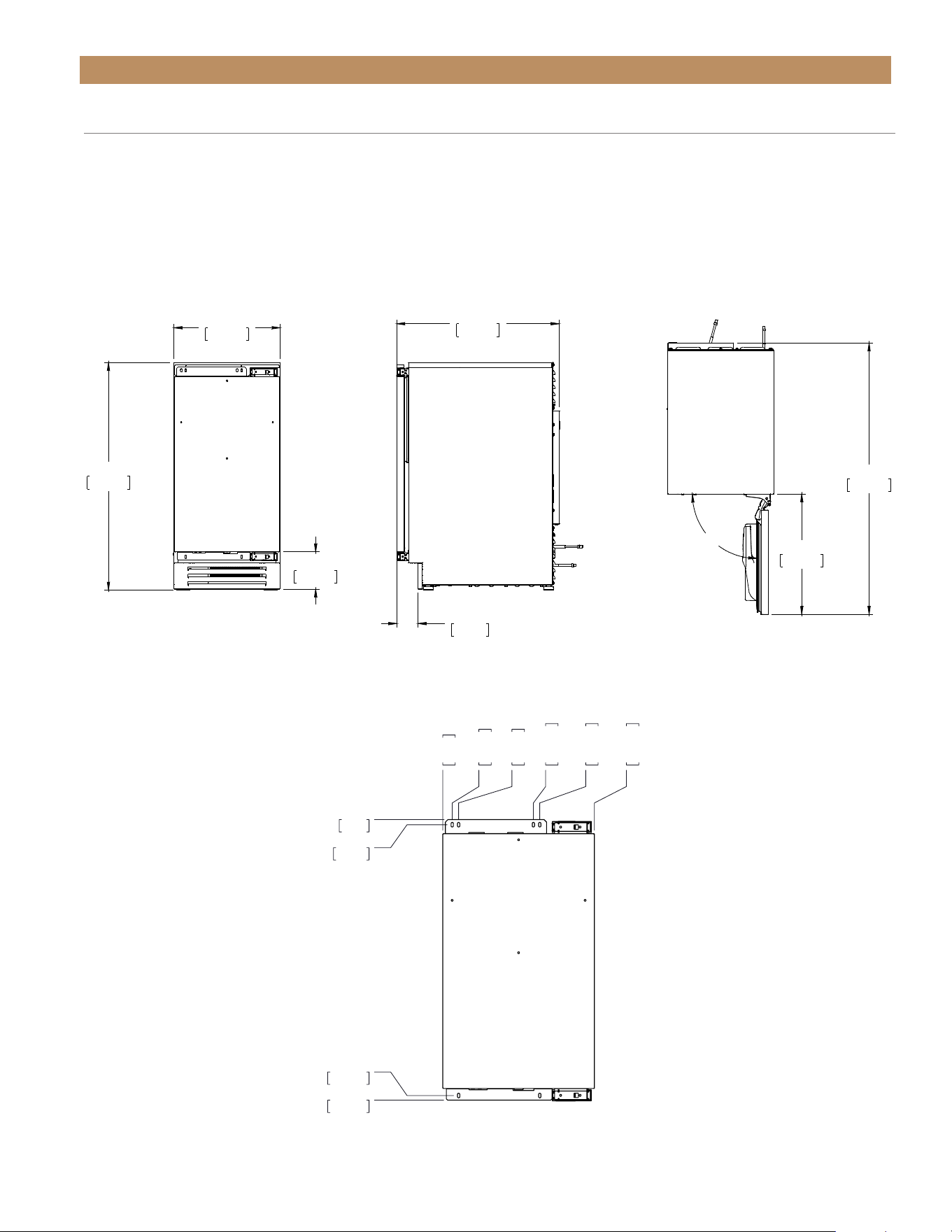
14 7/8"
377mm
31 7/8"
810mm
22 13/16"
580mm
3 23/32"
95mm
23 19/32"
599mm
15/16"
24mm
20 1/4"
514mm
16 29/32"
429mm
38 1/32"
966mm
90°
PRIOR TO INSTALLATION
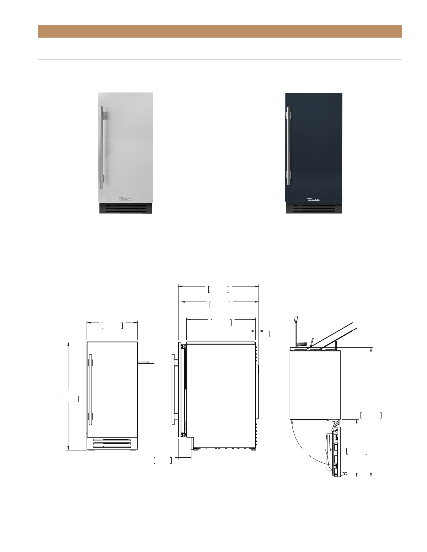
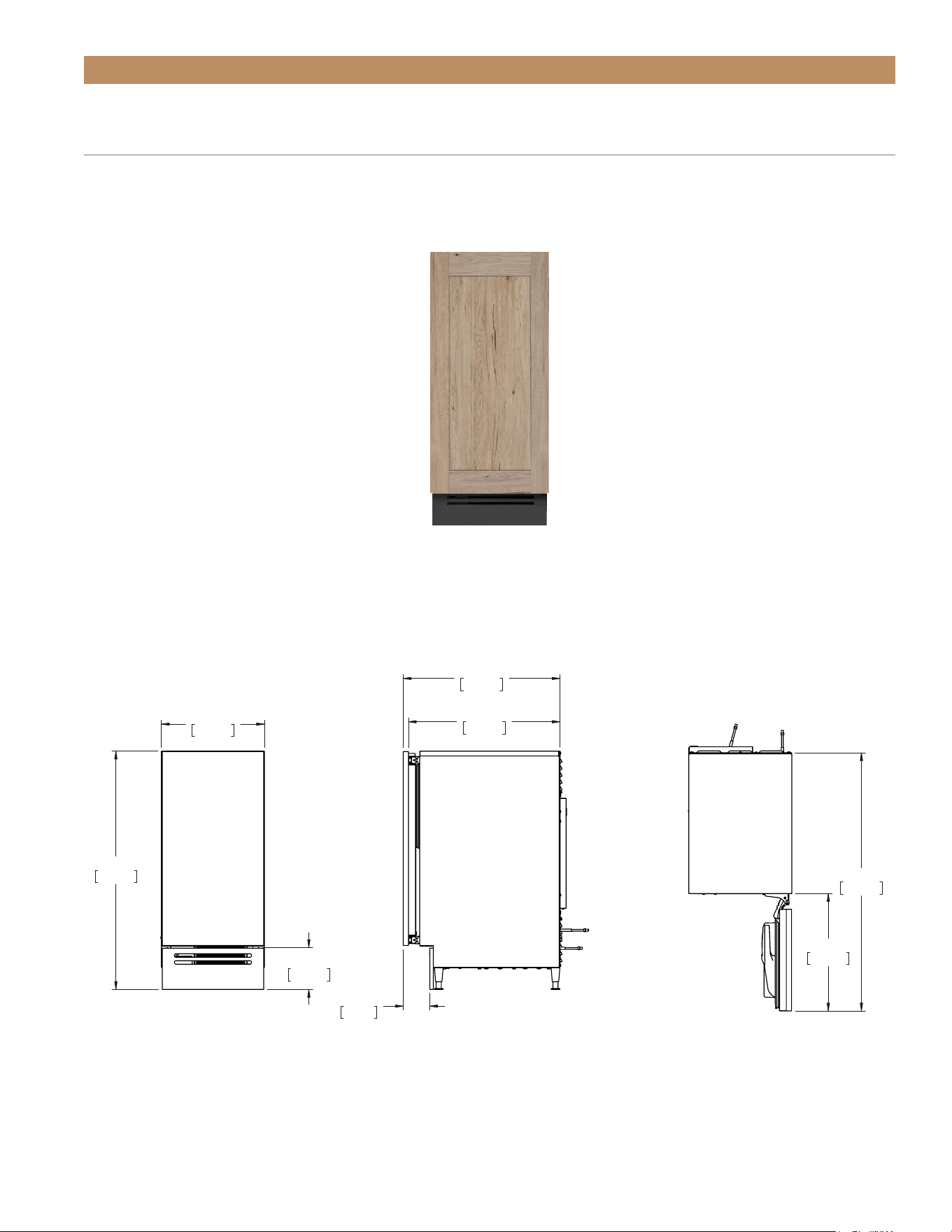
PLAN VIEW DIMENSIONS
STAINLESS STEEL DOOR
STAINLESS & FINISHED SOLID UNITS
Dimensions may vary by ± 1/8" (3.2 mm)
CUSTOM FINISH (DSK)
TUIADA-15-RS-A~104-H04TUIADA-15-RS/LS-A~S
SIDE TOPFRONT
TRUE RESIDENTIAL
®
P#829074 TEC_TM_157 REV. B EN08/22/2022Page 20 of 80
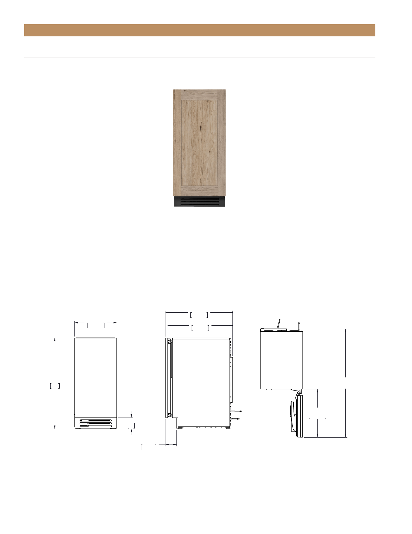
SIDE TOPFRONT
TUIADA-15-RS/LS-A~O
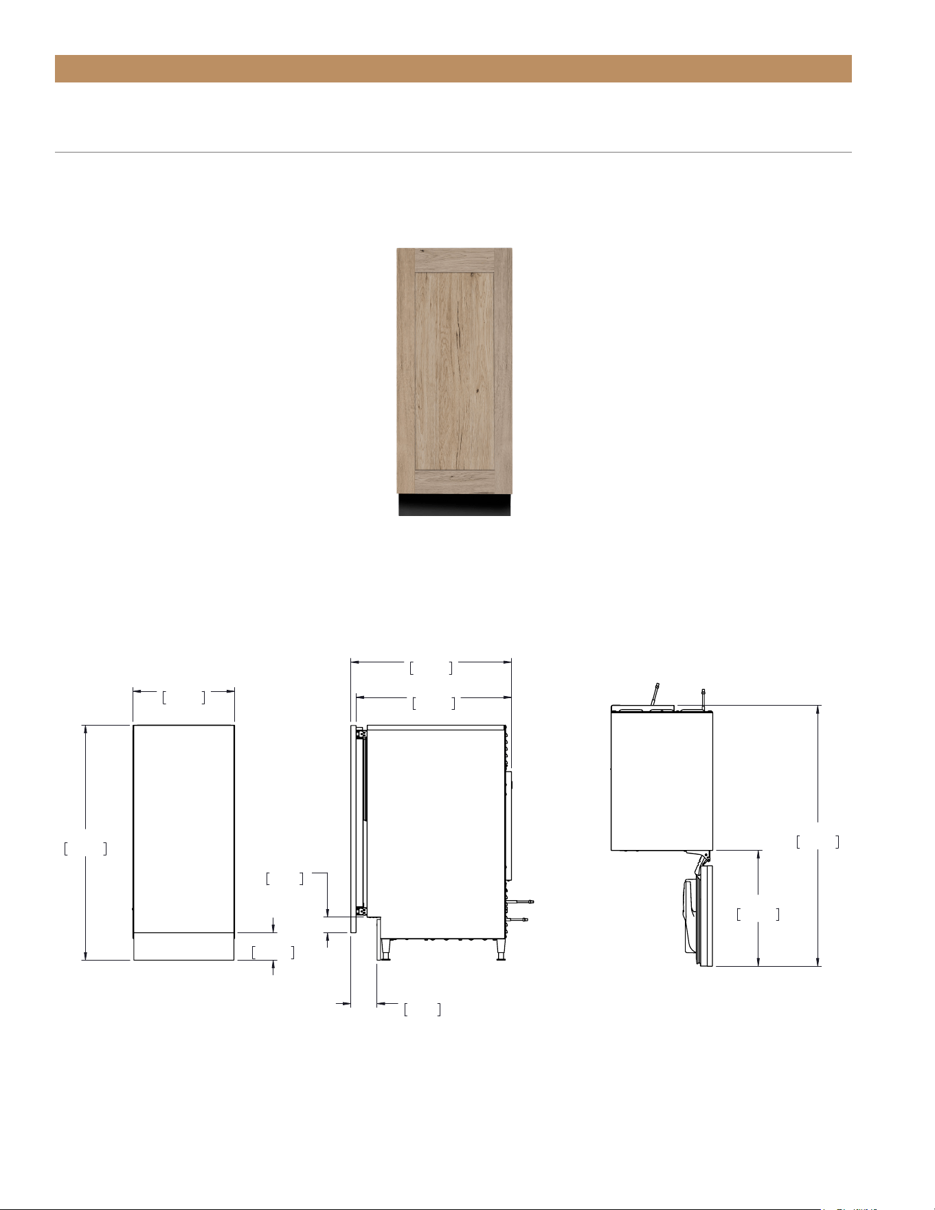
PRIOR TO INSTALLATION
SOLID OVERLAY UNITS
PLAN VIEW DIMENSIONS*
SOLID PANEL-READY DOOR (OP)
NOTE: Unit shown with overlay panel provided by others.
14 7/8"
377mm
31 13/16"
808
3 29/32"
99
3 27/32"
97mm
23 1/2"
597mm
22 3/4"
578mm
16 7/8"
429mm
38"
965mm
OVERLAY EXACT WITH REG LEGS
08/15/22
Dimensions may vary by ± 1/8" (3.2 mm)
*Depth measurement includes 3/4" (19 mm) thick panel (not provided by True)
ADA HEIGHT 15" TRUE ICE
®
MACHINE INSTALL GUIDETEC_TM_157 REV. B EN
08/22/2022
Page 21 of 80
OPTIONAL INSTALLATION
ALLOWABLE AIR TEMPERATURES
Air Temperature Water Temperature Water Pressure
Minimum 40˚F (4.4˚C) 40˚F (4.4˚C) 20 psig (1.4 bar)
Maximum 100˚F (37.8˚C) 100˚F (37.8˚C) 80 psig (5.5 bar)
Avoid running
wires or
plumbing in this
area.
SURROUNDING CABINETRY
SURROUNDING CABINETRY
9"
(228.6 mm)
16"
(406.4 mm)
9
11/16
"
(233.1 mm)
FRONT VIEW OF CABINETRY OPENING
OPTIONAL INSTALLATION ROUGH
OPENING & PLAN VIEWS
[34-1/2" (877 MM) OPENING]
Optional installations use combinations of 2-1/2"
(64 mm) leveling legs, 6" (153 mm) grill, and custom
overlay panels to raise (or appear to raise) the overall
height of the unit. This section shows the cabinet
specifications for the following configurations:
A. 2-1/2" leveling legs and 6" grill (stainless steel unit)
B. 2-1/2" leveling legs, 6" grill, and standard door
overlay panel
C. 2-1/2" leveling legs, 6" grill, and tall door overlay
panel.
D. Standard leveling legs and tall door overlay panel
ROUGH
OPENING
HEIGHT
34-1/2" min
(876.3 mm)
ROUGH
OPENING
WIDTH
15" min
(381 mm)
ROUGH
OPENING
DEPTH
24" min
(609 mm)
OPTIONAL INSTALLATION ROUGH OPENING
Please see the recommended dimensions for a
nonstandard rough opening below. The height includes
2-1/2" (64 mm) leveling legs in the measure. For unit
specifications, please see Optional Installation Plan
Views starting on page 23.
ANTI-SWEAT FOAM END PANELS
When installing two or more True units side-by-side,
be sure to leave at least 5/8" (16 mm) gap between the
cabinets, or install foam pads between the cabinets
and on any side without this gap, to prevent moisture
from developing on applications.
If installing ant-sweat foam end panels, True
recommends applying a panel to each of the
units being joined together. To order foam pads,
contact our parts department at 844-849-6226 or
TrueResidentialParts@TrueMfg.com.
TRUE RESIDENTIAL
®
P#829074 TEC_TM_157 REV. B EN08/22/2022Page 22 of 80
OPTIONAL INSTALLATION
WATER LINE, DRAIN LINE, AND POWER CORD LOCATIONS
The ice maker must be installed with adequate clearance for water and drain connections at the rear of the unit.
7 15/32"
190mm
4 29/32"
125mm
2 3/8"
61mm
1 23/32"
44mm
POWER CORD
2 9/32"
58mm
WATER LINE
3 21/32"
93mm
DRAIN LINE
ADA HEIGHT 15" TRUE ICE
®
MACHINE INSTALL GUIDETEC_TM_157 REV. B EN
08/22/2022
Page 23 of 80
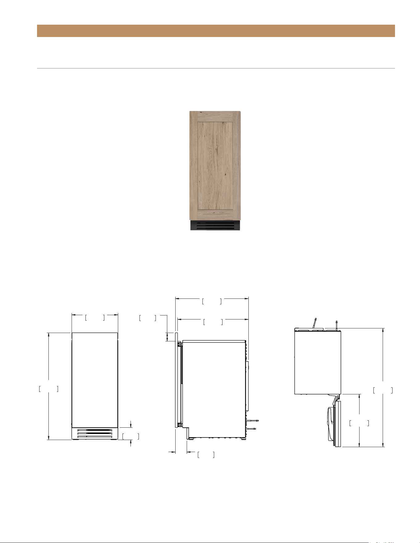
OPTIONAL INSTALLATION PLAN VIEWS
PLAN VIEW DIMENSIONS*
A & B. 2-1/2" (64 MM) LEVELING LEGS WITH 6" (153 MM) GRILL AND STANDARD
DOOR (OVERLAY PANEL)
To order a 6" (153 mm) grill (stainless steel or black) or the 2-1/2" (64 mm) leveling legs please contact our parts
department at 844-849-6226 or TrueResidentialParts@TrueMfg.com. For custom panel specifications, please see
“Custom Overlay Panel Specifications" starting on page 26.
SIDE TOPFRONT
Dimensions may vary by ± 1/8" (3.2 mm)
*Depth measurement includes 3/4" (19 mm) thick panel (not provided by True)
34 1/4"
870mm
14 7/8"
377mm
6"
153mm
22 5/8"
575mm
21 7/8"
556mm
3 27/32"
97mm
37 1/8"
943mm
16 7/8"
429mm
OLAY EXACT 3 INCH LEGS
01/06/22
TUIADA-15-RS/LS-A~O
TRUE RESIDENTIAL
®
P#829074 TEC_TM_157 REV. B EN08/22/2022Page 24 of 80
Dimensions may vary by ± 1/8" (3.2 mm)
*Depth measurement includes 3/4" (19 mm) thick panel (not provided by True)
SIDE TOPFRONT
TUIADA-15-RS/LS-A~O
OPTIONAL INSTALLATION PLAN VIEWS
C. 2-1/2" (64 MM) LEVELING LEGS WITH 6" (153 MM) GRILL AND TALL DOOR
OVERLAY PANEL (DOOR EXTENDS DOWN)
To order a 6" (153 mm) grill (stainless steel or black) or the 2-1/2" (64 mm) leveling legs please contact our parts
department at 844-849-6226 or TrueResidentialParts@TrueMfg.com. For custom panel specifications, please see
“Custom Overlay Panel Specifications" starting on page 26.
PLAN VIEW DIMENSIONS*
NOTE: Unit shown with overlay panel provided by others.
14 7/8"
377mm
34 1/4"
870mm
4"
102mm
23 1/2"
597mm
22 3/4"
578mm
2 1/4"
57mm
3 27/32"
97mm
16 7/8"
429mm
38"
965mm
OLAY EXTEND DOWN 3 IN LEG
01/06/22
ADA HEIGHT 15" TRUE ICE
®
MACHINE INSTALL GUIDETEC_TM_157 REV. B EN
08/22/2022
Page 25 of 80
OPTIONAL INSTALLATION PLAN VIEWS
PLAN VIEW DIMENSIONS
D. STANDARD LEVELING LEGS WITH TALL DOOR OVERLAY PANEL
(DOOR EXTENDS UP)
For custom panel specifications, please see “Custom Overlay Panel Specifications" starting on page 26.
SIDE TOPFRONT
*Measures include 3/4" (19 mm) thick panel (not provided by True)
Dimensions may vary by ± 1/8" (3.2 mm)
TUIADA-15-RS/LS-A~O
14 7/8"
377mm
3 7/8"
98mm
34 1/4"
870mm
2 23/32"
69mm
23 1/2"
597mm
22 3/4"
578mm
3 23/32"
94mm
38"
965mm
16 7/8"
429mm
OLAY EXTEND UP REG LEG
01/06/22
TRUE RESIDENTIAL
®
P#829074 TEC_TM_157 REV. B EN08/22/2022Page 26 of 80
OPTIONAL INSTALLATION
CUSTOM OVERLAY PANEL SPECIFICATIONS
Overlay units can be fitted with custom panels to
match adjacent cabinetry. Please see this section for
recommended panel specifications.
NOTE! PANEL HEIGHT CAN EXCEED THESE
RECOMMENDATIONS BASED ON ROUGH
OPENING SIZE AND CABINET SPECIFICATIONS.
True units assume 3/4" (19 mm) thick overlay panels
of the specified width (see spefiications tables) to
be supplied by the end user or others. Thicker/wider
panels increase the potential for panel interference.
See fig. 1.
NOTE! THIS INTERFERENCE CAN BE
MINIMIZED WITH A 90° DOORSTOP. SEE
“90° DOORSTOP INSTALLATION” (PAGE 48).
FIG. 1.
Panels 3/4" (19 mm) thick are designed to not interfere with
surrounding units or cabinetry.
115º
3/4" (19 mm)
panel(s)
ADA HEIGHT 15" TRUE ICE
®
MACHINE INSTALL GUIDETEC_TM_157 REV. B EN
08/22/2022
Page 27 of 80
PRIOR TO INSTALLATION
For panel installation instructions, please see “Custom
Overlay Panel Installation" (page 32).
STANDARD SOLID DOOR OVERLAY PANEL - OPTIONAL INSTALLATIONS A & B
SPECIFICATIONS
Panel Width 14-5/8" (371.5 mm)
Panel Height 27-7/8" (708 mm)
Panel Depth 3/4" (19 mm) max
Panel Weight 10lb (4.5kg) max
Rail Style Dimension 2" (50.8 mm) min
27-7/8"
(708 mm)
14-5/8"
(371.5 mm)
TRUE RESIDENTIAL
®
P#829074 TEC_TM_157 REV. B EN08/22/2022Page 28 of 80
PRIOR TO INSTALLATION
Overlay units can be fitted with custom panels to
match adjacent cabinetry. For example, the tall door
overlay panel can extend the apparent height of the
unit or disguise the actual height of a 6" (600 mm)
grill. For more detail, please see “Optional Installations
Rough Opening & Plan Views" starting on page 21.
Please see below for panel specifications.
TALL DOOR OVERLAY PANEL – OPTIONAL INSTALLATIONS C & D
SPECIFICATIONS
Panel Width 14-5/8" (371.5 mm)
Panel Height 30-1/8" (765.2 mm)
Panel Depth 3/4" (19 mm) max
Panel Weight 10lb (4.5kg) max
Rail Style Dimension 2" (50.8 mm) min
30-1/8"
(765.2 mm)
14-5/8"
(371.5 mm)
ADA HEIGHT 15" TRUE ICE
®
MACHINE INSTALL GUIDETEC_TM_157 REV. B EN
08/22/2022
Page 29 of 80
PRIOR TO INSTALLATION
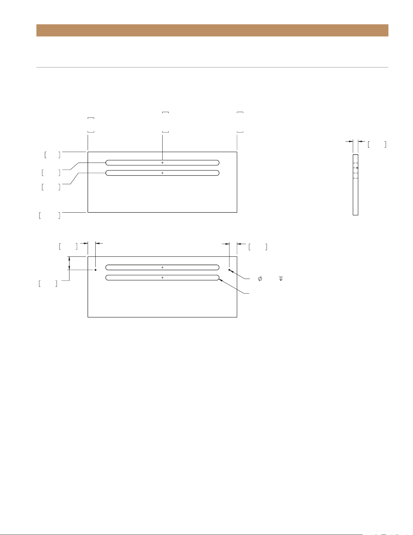
6" (153 MM) OVERLAY LOUVER GRILL TEMPLATE – OPTIONAL INSTALLATIONS
A , B, & C
2-1/2" (64 mm) leveling legs create a visible gap between the bottom of the grill and the floor. To conceal this gap
with overlay, please see the custom overlay louver grill template below.
0"
0mm
1 1/16"
27mm
2 1/16"
52mm
5 15/16"
151mm
0"
0mm
7 5/16"
186mm
14 5/8"
371mm
7 5/16"
186mm
1/2"
13mm
3/4"
19mm
1 5/16"
33mm
3/4"
19mm
2X
.1250
.1250
2X .5000 X 11.1250 THRU
BACK
TRUE RESIDENTIAL
®
P#829074 TEC_TM_157 REV. B EN08/22/2022Page 30 of 80
PRIOR TO INSTALLATION
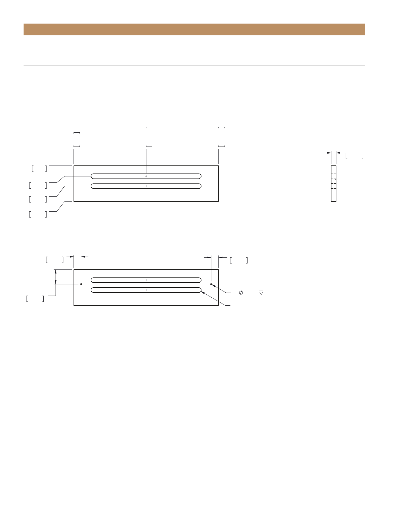
4" (102 MM) STANDARD OVERLAY LOUVER GRILL TEMPLATE –
OPTIONAL INSTALLATION D
If so desired, you can replace the kickplate with a custom overlay louver grill. Please see the template below.
0"
0mm
1 1/16"
27mm
2 1/16"
52mm
3 5/8"
92mm
0"
0mm
7 5/16"
186mm
14 5/8"
371mm
7 5/16"
186mm
1/2"
13mm
3/4"
19mm
1 15/32"
37mm
3/4"
19mm
2X
.1250
.1250
2X .5000 X 11.1250 THRU
BACK
ADA HEIGHT 15" TRUE ICE
®
MACHINE INSTALL GUIDETEC_TM_157 REV. B EN
08/22/2022
Page 31 of 80
"8/7 61
mm824
°09
"
83
mm569
"23/32 22
mm775
"23/13 2
mm57
"8/7 41
mm773
"61/31 13
mm808
"23/7 5
mm231
YALREVO ON
12/71/21
PRIOR TO INSTALLATION
• Custom door overlay panels must be at least
14-5/8" (375.1 mm) x 23-13/16" (605.1 mm) x
3/4" (19 mm) to cover the panel-ready door front.
Your panel dimensions may vary based on the
rough opening size and / or adjacent cabinetry
specifications.
• For correct hinge operation, be sure to install door
overlay panels with its hinge side aligned flush with
the door front’s hinge side.
• Doors have pre-drilled holes to assist overlay panel
installation. See fig. 1.
ADDITIONAL DOOR OVERLAY PANEL INFORMATION
SIDE TOPFRONT
FIG. 1.
Door front bracket hole and pre-drilled hole locations and measurements
0"
0mm
29/32"
23mm
1 17/32"
39mm
8 23/32"
222mm
9 11/32"
237mm
14 5/8"
371mm
0"
0mm
1/2"
13mm
26 19/32"
675mm
27 1/32"
687mm
DOOR ASM COMP RH
R

TRUE RESIDENTIAL
®
P#829074 TEC_TM_157 REV. B EN08/22/2022Page 32 of 80
PRIOR TO INSTALLATION
CUSTOM OVERLAY PANEL
INSTALLATION
Your new ice machine comes with articulating, or soft-
closing, hinges. The hinges can be installed on either
the left of right to change the direction the door opens.
Before installing panels, be sure the door assembly is
oriented as desired. See “Reversing Door" (page 74).
Please closely read all instructions before installing
your panels.
REQUIRED TOOLS
Required tools include (but may not be limited to) the
following.
• Surface protection*
• 2+ Clamps ≥ 2" (51 mm)
• 1/8" Hex Head Allen Wrench
• Phillips Screwdriver or Bit Driver
• 1/8" Drill Bit
• (Qty 6) #6 x 1/2" Screws**
• Drill
*Cardboard, moving blanket, foam padding, etc.
**Screw type varies by panel material.
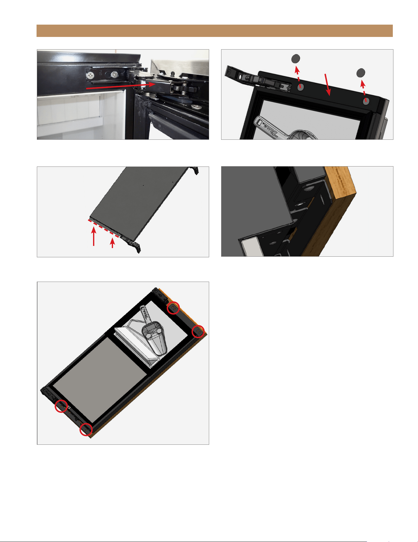
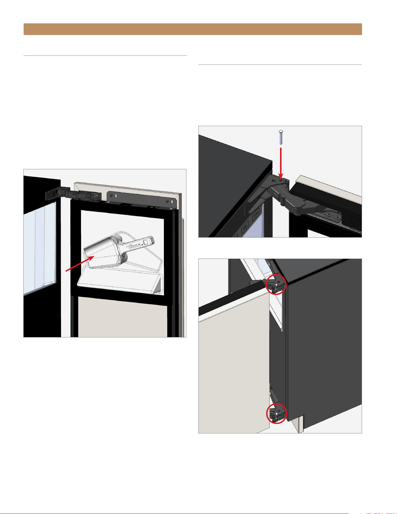
PROCEDURE
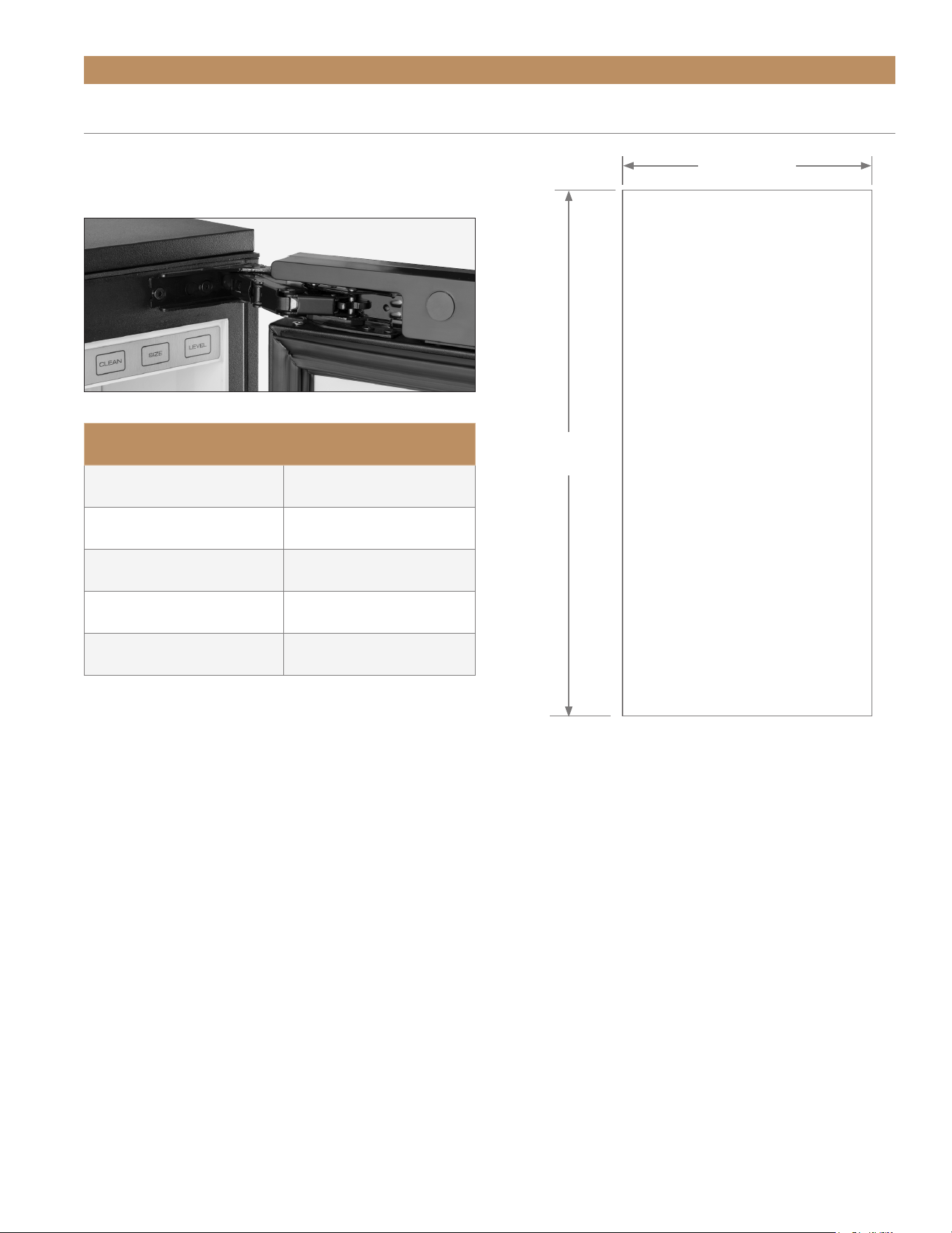
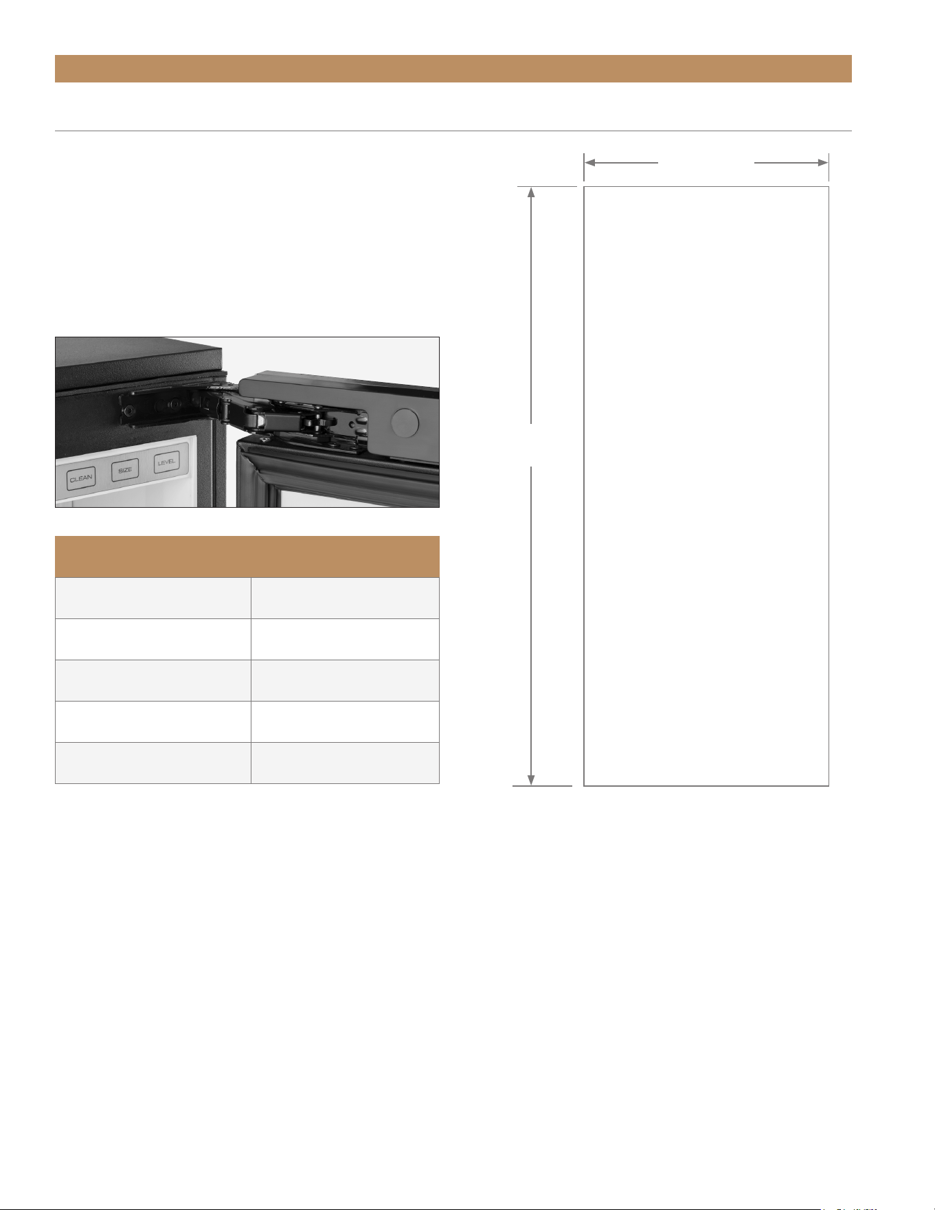
1. Carefully lay the door overlay panel face down on a
protected surface.
2. With a 1/8" hex head Allen wrench, loosen the
cabinet hinge bolts. Then, remove the door.
See fig. 1.
NOTE: DO NOT REMOVE THE HINGE FROM THE
DOOR ASSEMBLY.
3. If NSF Cover is present, carefully pry screw caps
from the cover to access the door bracket screws.
See fig. 2.
4. Place the door front face down on the overlay
panel. Then, align the bottom door bracket’s
bottom edge with the overlay panel’s bottom edge.
See figs. 3 and 4.
5. Clamp the door assembly panel.
NOTE: IF THE CLAMP JAWS ARE NOT PADDED,
INSERT PADDING BETWEEN THE CLAMP AND
THE OVERLAY TO PROTECT THE PANEL’S
FINISH.
6. If desired, install a handle before proceeding to the
next step. For best installation, fasten the handle
with recessed screws.
7. With a 1/8" drill bit, carefully drill pilot holes into
the door front. See fig. 5.
NOTE: TAKE CARE TO NOT DRILL THROUGH THE
FRONT OF THE PANEL.
8. With the appropriate hardware, fasten the overlay
panel to the door front. Then, remove the clamps.
9. Install the door assembly. Be sure to fully tighten
the hinge screws.
10. Verify the door closes correctly and seals without
gaps. Adjust the door as needed; see “Door
Adjustment" (page 77).
ADA HEIGHT 15" TRUE ICE
®
MACHINE INSTALL GUIDETEC_TM_157 REV. B EN
08/22/2022
Page 33 of 80
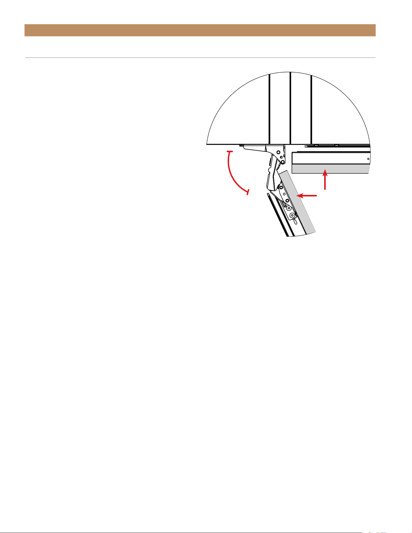
PRIOR TO INSTALLATION
FIG. 1.
Slide the door off the hinge bolts through the keyhole slots.
FIG. 3.
Align along the bottom door bracket edge. Front of door assembly
shown.
FIG. 4.
The bottom edge of the panel should align with the bracket
as shown.
FIG. 2.
Remove the NSF cover screw caps.
NSF Cover
Screw cap
Align along
this edge
FIG. 5.
Carefully fasten the overlay panel to the door front.
TRUE RESIDENTIAL
®
P#829074 TEC_TM_157 REV. B EN08/22/2022Page 34 of 80
The unit is approved by UL for outdoor installation.
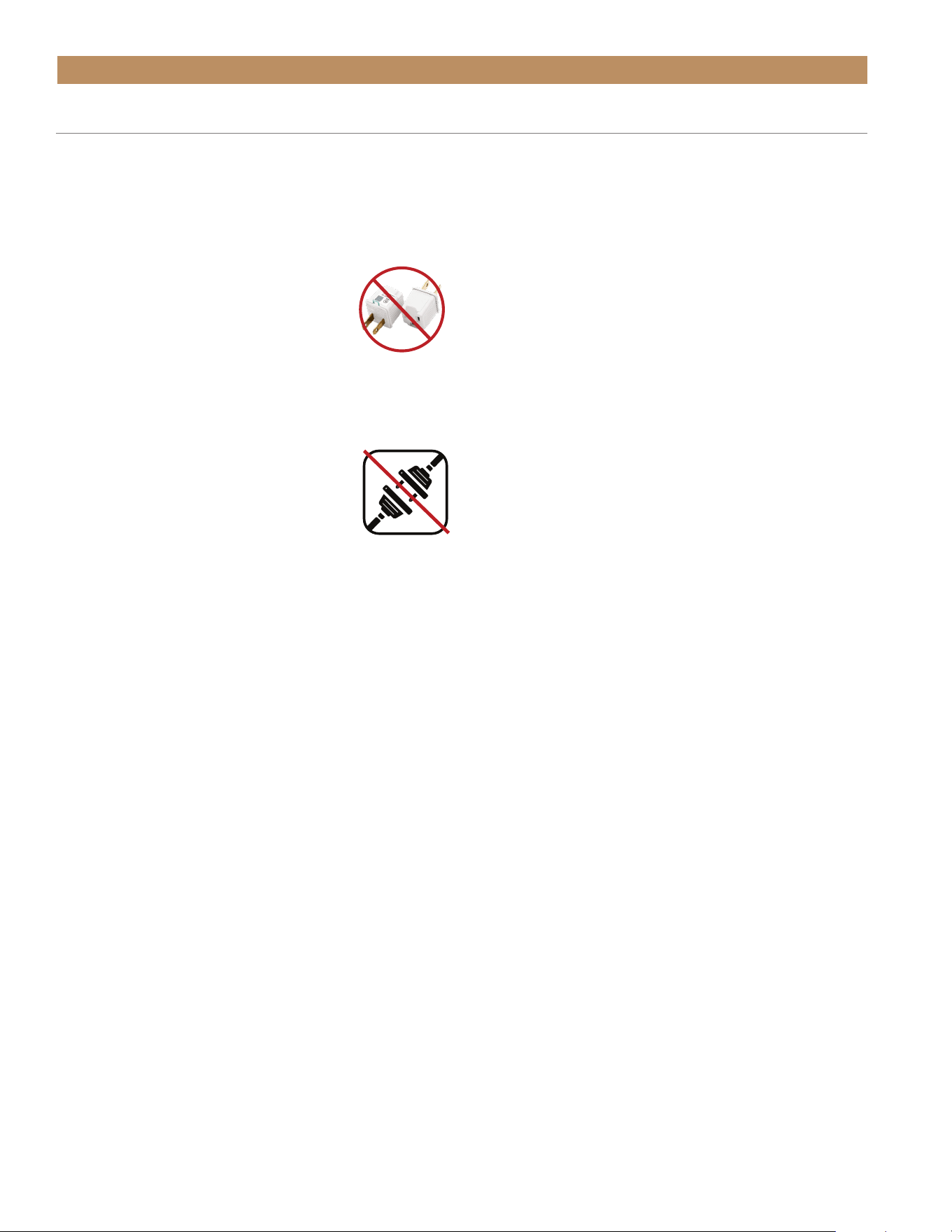
USE OF ADAPTER PLUGS
NEVER USE AN ADAPTER PLUG! An adapter plug alters the
original OEM plug configuration when connecting it to
a power source.
TRUE will not warranty any refrigerator/
freezer that has been connected to an
adapter plug.
USE OF EXTENSION CORDS
NEVER USE AN EXTENSION CORD! An extension cord is
determined to be any component that adds
length to the original OEM power cord
when connecting it to a power source.
TRUE will not warranty any refrigerator/
freezer that has been connected to an extension cord.
HOW TO CONNECT ELECTRICITY
• The ice maker should always be plugged into a
dedicated electrical circuit. This provides the best
performance and prevents building wiring circuits
from being overloaded, which could cause
a fire hazard from overheated wires.
• Before your new unit is connected to a power
supply, check the incoming voltage with a voltmeter.
If the recorded voltage is less than the rated voltage
for operation (+/-5%) and amp rating, correct
immediately. Refer to cabinet data plate for this
voltage requirement.
• The electrical outlet must be within 36" (914.4 mm)
of the center of the back wall of the ice maker’s
final location. Outlet must be flush with wall and
comply with local electrical codes.
• The wall outlet and circuit should be checked by
a licensed electrician to make sure the outlet is
properly grounded.
• The power cord of this appliance is equipped
with a 3-prong (grounding) plug which mates
PRIOR TO INSTALLATION
with a standard 3-prong (grounding) wall outlet to
minimize the possibility of electric shock hazard
from this appliance. A 115v AC, 60 Hz, 15 amp
circuit breaker and electrical supply are required.
• If the outlet is a standard 2-prong outlet, it is your
personal responsibility and obligation to have it
replaced with the properly grounded wall outlet.
• DO NOT, under any circumstances, cut or remove the
ground prong from the power cord. For personal
safety, this appliance must be properly grounded.
• When moving the ice maker, for any reason, be
careful not to roll over or damage the power cord.
• Repair or replace immediately all power cords that
have become frayed or otherwise damaged. DO NOT
use a power cord that shows cracks or abrasion
damage along its length or at either end.
• If the supply power cord is damaged, it should be
replaced with original equipment manufacturer
(OEM) components. To avoid hazard this should be
done by a licensed service provider.
• NEVER unplug your ice maker by pulling on the
power cord. Always grip plug firmly and pull straight
out from the outlet.
ELECTRICAL INSTALLATION & SAFETY
ADA HEIGHT 15" TRUE ICE
®
MACHINE INSTALL GUIDETEC_TM_157 REV. B EN
08/22/2022
Page 35 of 80
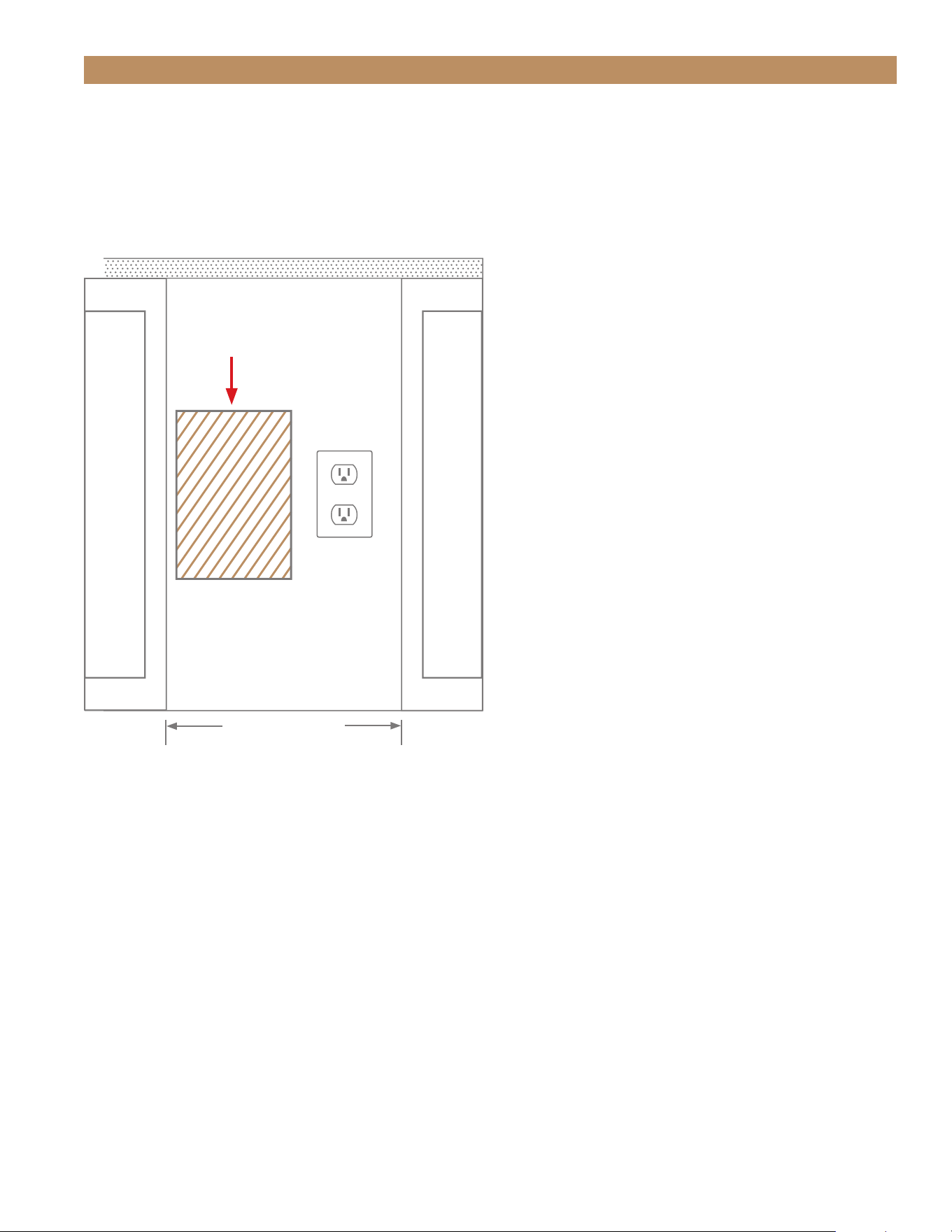
PRIOR TO INSTALLATION
ELECTRICAL OUTLET LOCATION
To minimize the depth of the cutout opening, the
electrical outlet must be positioned as shown below.
Outlet must be flush with wall.
Rear wall of cut out
DO NOT INSTALL
OUTLET IN THIS AREA!
Countertop
15" (381 mm)
opening
TRUE RESIDENTIAL
®
P#829074 TEC_TM_157 REV. B EN08/22/2022Page 36 of 80
PRIOR TO INSTALLATION
WATER
TEMPERATURE
WATER PRESSURE
Minimum 40˚F (4.4˚C) 20 psig (1.4 bar)
Maximum 100˚F (37.8˚C) 80 psig (5.5 bar)
PLUMBING MATERIAL
Water Supply
• 1/4" O.D. copper
• braided stainless steel
• PEX tubing and compression fittings
(1/4" lines and fittings not provided by
TRUE)
Drain Connection
1/2" O.D. Female NPT Fitting
(see fig. 1.)
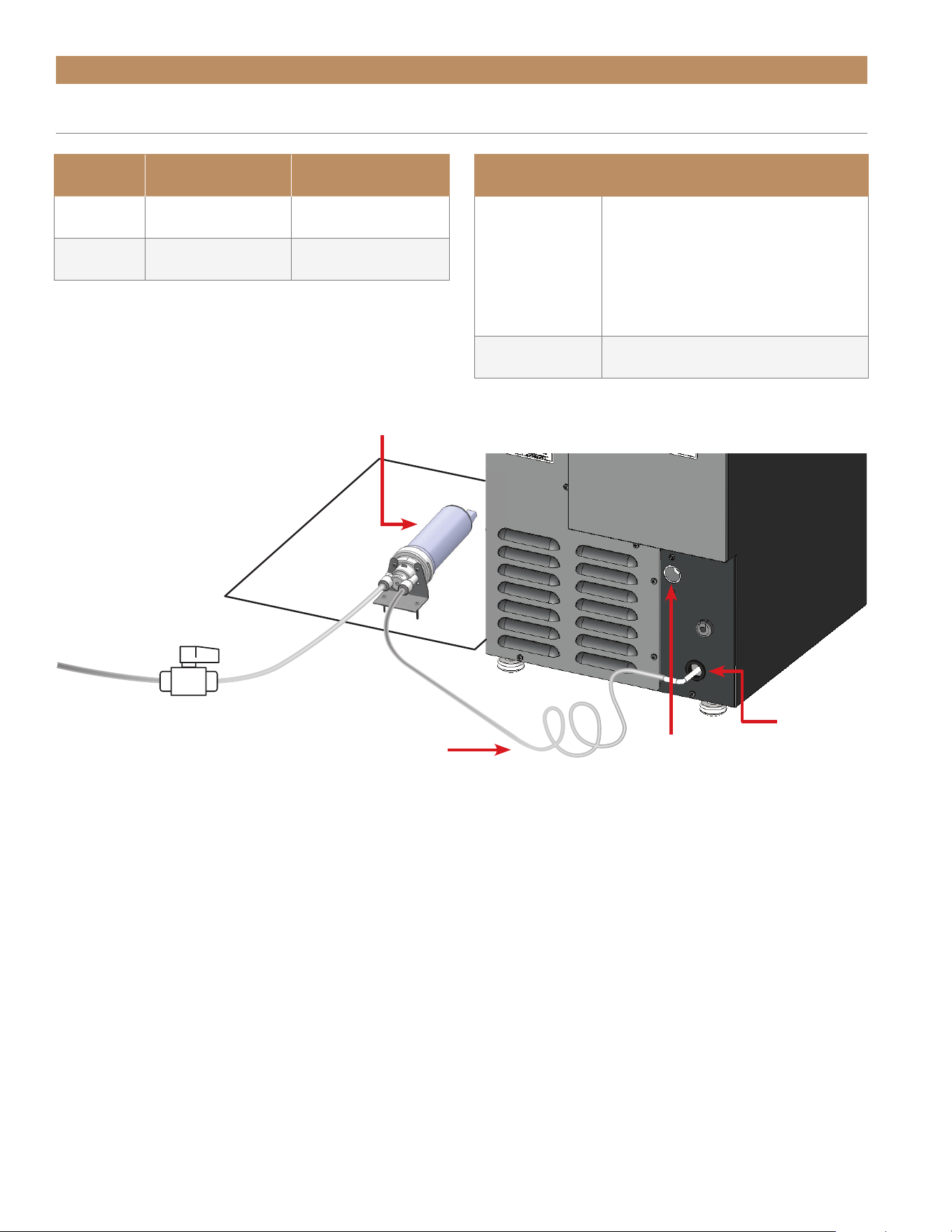
FIG. 1.
Example of correct water supply and water filter installation.
W A T E R
FILTER
SHUT-OFF
VALVE
48" (1219.2 mm)
SUPPLY HOSE
(Provided by True)
Extra hose coiled for
proper servicing
D R A I N
FITTING
Surrounding
cabinetry
TO WATER
SUPPLY
W A T E R
INLET
PLUMBING REQUIREMENTS & INSTALLATION

ADA HEIGHT 15" TRUE ICE
®
MACHINE INSTALL GUIDETEC_TM_157 REV. B EN
08/22/2022
Page 37 of 80
PRIOR TO INSTALLATION
WATER SUPPLY
• The ice maker comes with a 48" (1219.2 mm) of
1/4" O.D. PEX tubing for connecting the water filter
to the unit. See fig. 1 for the ice machine’s water
inlet location.
• DO NOT connect the water supply directly to the
icemaker. Connect the water supply to the water
filter. Tubing for connecting water filter to water
supply NOT provided by TRUE.
• Failure to install the water filter will void the
machine warranty.
• The provided water filter must be installed within
30" (762 mm) of the ice machine’s water inlet.
• Water pressure must be between 20-80 psig
(1.4. 5.5 bar). If the water pressure exceeds
the maximum pressure, install a water pressure
regulator.
• A reverse osmosis system can be used if there is
constant water pressure of 20-80 psig (1.4-5.5 bar).
• Cold water supply required. Incoming water
temperature must remain 40-100°F (4.4-7.8°C).
• Never connect to a hot water supply. Be sure all
hot water restrictors installed for other equipment
are working, such as check valves on sink faucets,
dishwashers, etc.
• Water regulating valve recommended for pressures
higher than 80 psig (5.5 bar). If so desired,
installing a water hammer valve can reduce the
noise and shock from the valve closing.
• Use tight-fitting, leak-proof permanent connections
for the water supply. Soldered connections are
always best. In the absence of soldering, use
compression-type fittings for more reliability.
• While push fittings are acceptable, they are prone
to leaks when installed incorrectly and/or not
according to the manufacturer’s specifications.
• TRUE recommends coiling extra length of supply
hose behind the machine to allow proper servicing
of the unit. See fig. 1.
• Connect the water supply line to the house supply
with an easily accessible shut-off valve in your
installation. See fig. 1.
• Insulate the supply line to prevent condensation.
• When switching to PEX, the tubing must be rated
for 150 psi (10.3 bar) burst pressure minimum and
180°F (82.2°C).

TRUE RESIDENTIAL
®
P#829074 TEC_TM_157 REV. B EN08/22/2022Page 38 of 80
PRIOR TO INSTALLATION
WATER FILTER INSTALLATION
NOTE: FAILURE TO INSTALL THE WATER FILTER
WILL VOID THE MACHINE WARRANTY.
The provided water filter removes any unpleasant taste
and odor, as well as inhibiting scale.
• The ice maker comes with a 48" (1219.2 mm) of
1/4" O.D. PEX tubing for connecting the water filter
to the unit.
NOTE: TUBING FOR CONNECTING WATER FILTER
TO THE WATER SUPPLY NOT PROVIDED BY TRUE.
SEE “WATER SUPPLY" (PAGE 37)
• Install the water filter within 30" (762 mm) of the
ice machine’s water inlet.
• Do not install the water filter behind the unit.
• The filter life expectancy is 12 months for low-scale
water and 6 months for high-scale water.
• The ice maker monitors how long the filter has been
in operation; the display will show rtr when the filter
needs to be replaced. See water filter replacement
instructions on page 61.
• To order a replacement water filter, go to
www.store.trueresidential.com/collections/
maintenance-1 or contact our parts department at
844-849-6226 or TrueResidentialParts@TrueMfg.
com.
CAUTION: DO NOT ALLOW THE ICE MACHINE TO
BE EXPOSED TO TEMPERATURES BELOW 32°F
(0°C) WITHOUT WINTERIZING THE MACHINE AS
THIS WILL CAUSE ANY WATER IN THE MACHINE
TO FREEZE. FAILURES CAUSED BY EXPOSURE TO
FREEZING TEMPERATURES ARE NOT COVERED BY
THE WARRANTY.
REQUIRED TOOLS
• (2) #8 Screws*
• Appropriate Bit Driver
• 1/8" Drill Bit (optional)
• Marking Utensil (optional)
• Drill
*Screw type varies by surface material.
PROCEDURE
1. Position the water filter head assembly. Then mark
the bracket hole locations.
2. Carefully drill pilot holes in the marked locations.
3. Install the water filter head assembly.
NOTE: BE SURE THE BRACKET IS SECURELY
FASTENED BEFORE INSTALLING THE FILTER.
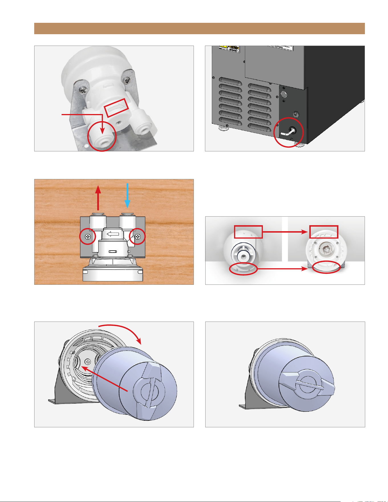
4. Connect the water filter head to the icemaker water
inlet (tubing provided by TRUE). See figs. 2 and 3.
5. Connect the water filter head to the water supply.
(Tubing NOT provided by TRUE, see “Water
Supply” on page 37). See fig. 3.
6. Apply the provided lubricant to the water filter
O-rings.
7. Align the filter with the filter head’s teeth. See fig.
3.
8. Insert the water filter and rotate the water filter
clockwise. See figs. 4 and 5.
9. Check all plumbing connections for leaks.
ADA HEIGHT 15" TRUE ICE
®
MACHINE INSTALL GUIDETEC_TM_157 REV. B EN
08/22/2022
Page 39 of 80
FIG. 4.
Align the water filter’s slots with the corresponding teeth in the
filter head.
PRIOR TO INSTALLATION
FIG. 1.
The water inlet has the strainer and is behind the direction arrow.
FIG. 5.
Insert the water filter and rotate it clockwise.
FIG. 6.
Installed water filter.
FIG. 3.
Water filter head inlet, outlet, and bracket screw locations. Top-
down view shown.
FIG. 2.
Ice machine water inlet location.
W A T E R
INLET
W A T E R
OUT
W A T E R
IN
TRUE RESIDENTIAL
®
P#829074 TEC_TM_157 REV. B EN08/22/2022Page 40 of 80
DRAIN CONNECTION
The True Ice
®
machine has a built-in drain pump.
WARNING: PROPER INSTALLATION REQUIRES
CONNECTION TO THE WATER SUPPLY AND
A DRAIN. THESE CONNECTIONS ARE THE
RESPONSIBILITIES OF THE INSTALLER. TRUE
WILL NOT WARRANT LEAKS OR DAMAGE
CAUSED BY IMPROPER INSTALLATION.
IMPROPER CONNECTIONS CAN RESULT IN
PERSONAL INJURY, PROPERTY DAMAGE AND
IMPROPER OPERATION. THE ICE MACHINE
MUST BE INSTALLED ACCORDING TO ALL
APPLICABLE NATIONAL, STATE AND LOCAL
CODES AND REGULATIONS.
DO NOT reduce drain connections any smaller than
3/8" O.D.
• 84” (2,133.6 mm) Clear PVC drain hose, 1/2"
male NPT connector, and 3/8" hose clamp
provided by True
• Using hose larger than 1/2" O.D. may require a
larger pump. A check valve may be required to
prevent excessive cycling of the drain pump.
• Be sure to use the correct O.D. hose for your
vertical rise to ensure the proper flowrate and
prevent drain time alarms. For more information,
see “Drain Time Alarm" (page 54).
• If the installation requires a vertical rise greater
than 84" (2,133.6 mm) include an external drain
pump to cover the additional required pumping
height. Connect the drain tube outlet from the ice
maker to the external drain pump inlet. Do not
remove the internal drain pump provided with the
ice maker. Altering the internal components in any
way will void the warranty.
• DO NOT USE HOSE SMALLER THAN 3/8" O.D.
• The floor drain must be large enough to
accommodate additional drainage.
• The drain pump discharge line must terminate at an
open site drain.
• Be sure to thoroughly inspect all connections after
installation to ensure there are no leaks. Use of
thread sealant recommended.
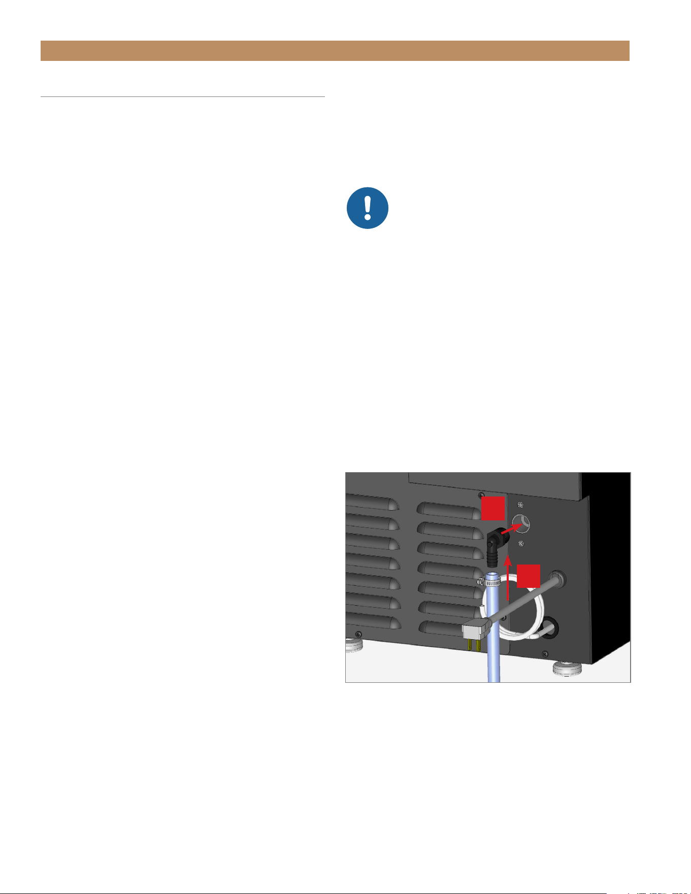
PRIOR TO INSTALLATION
PROCEDURE
1. Thread the 1/2" NPT connector into the drain
fitting. See fig. 1.
NOTE: THREAD SEALANT REQUIRED AND
TO BE SUPPLIED BY INSTALLER.
NOTICE: DO NOT OVERTIGHTEN THE
NPT CONNECTOR!
DO NOT TORQUE THE CONNECTOR
MORE THAN 50 IN-LB (5.65 NM).
THIS MAY CAUSE THE FITTING TO CRACK.
CHECK THE DRAIN FITTING FOR LEAKS
BEFORE COMPLETING THE INSTALLATION.
2. With the clamp on the hose, connect the clear
drain hose to the barbed fitting. See fig. 1.
3. Tighten the hose clamp.
NOTE: VERIFY THE ICE MAKER DRAINS
THROUGH TWO CYCLES WITHOUT ANY DRAIN
ALARM DURING INSTALLATION.
For more information, see “Drain Time Alarm"
(page 54).
FIG. 1.
Be sure to tightly clamp the drain line into the barbed fitting.
Thread sealant required.
1
2
ADA HEIGHT 15" TRUE ICE
®
MACHINE INSTALL GUIDETEC_TM_157 REV. B EN
08/22/2022
Page 41 of 80
PRIOR TO INSTALLATION
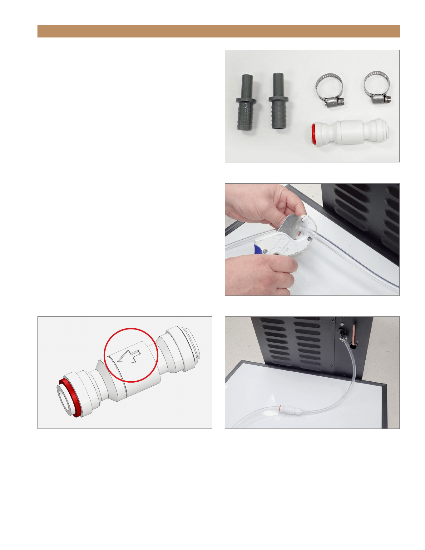
CHECK VALVE INSTALLATION
1. Locate the provided check valve kit. See fig. 2.
2. With tubing cutters, cut the drain line near the
connection point. See fig. 3.
3. With the water flow arrow (see fig. 4) pointing away
from the ice machine, connect the cut drain line
to the check valve. See fig. 5. Use the provided
adapters and clamps as needed.
4. Check the drain system for leaks.
FIG. 2.
Check valve kit shipped inside the ice machine.
FIG. 3.
Cut the drain line with tubing cutters.
FIG. 5.
Installed check valve.
FIG. 4.
Water flow arrow on the check valve.
TRUE RESIDENTIAL
®
P#829074 TEC_TM_157 REV. B EN08/22/2022Page 42 of 80
PRIOR TO INSTALLATION
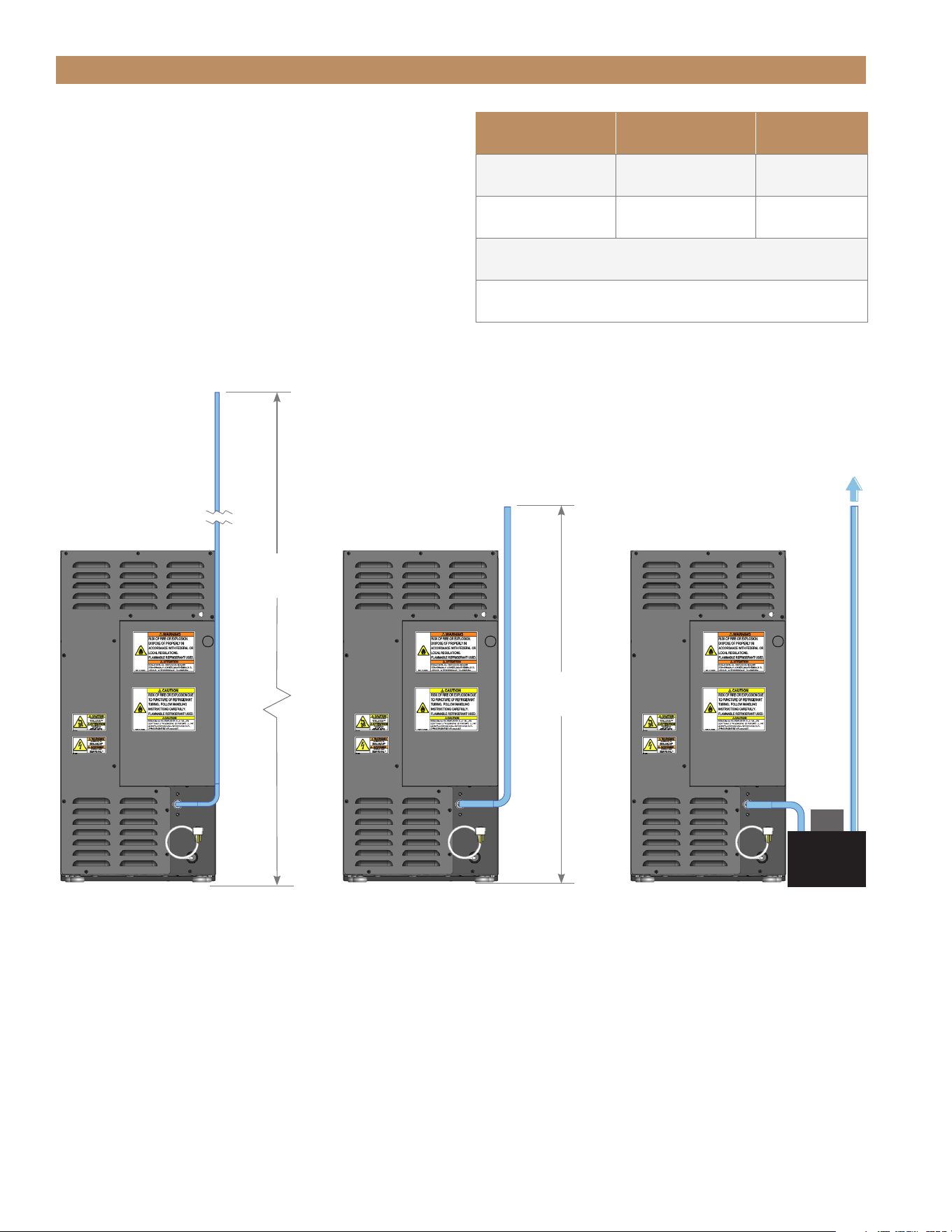
48" MAX
(1,219.2 mm)
84" MAX
(2,133.6 mm)
E x t e r n a l
Pump
1/2" O.D. HOSE
(NOT Provided by TRUE)
EXTERNAL PUMP3/8" O.D. HOSE
(Provided by TRUE)
MAXIMUM
VERTICAL RISE MAX RUN
3/8" O.D. Hose
(provided by TRUE)
84"
(2,133.6 mm)
100’
(30.84 m)
1/2" O.D. Hose 48" (1,219.2 mm) 100’ (30.84 m)
Hose larger than 1/2" O.D. may require an external pump.
Vertical rise higher that 84" will require external pump.
PUMP HEIGHTS
Do NOT exceed the Maximum Vertical Rise. See table
on right, diagrams below.

ADA HEIGHT 15" TRUE ICE
®
MACHINE INSTALL GUIDETEC_TM_157 REV. B EN
08/22/2022
Page 43 of 80
INSTALLATION
UNCRATING
LEVELING LEGS
LEVELING
KICKPLATE INSTALLATION
WATER FILTER INSTALLATION
PRESERVE THE MOMENT
®
TRUE RESIDENTIAL
®
P#829074 TEC_TM_157 REV. B EN08/22/2022Page 44 of 80
UNCRATING
REQUIRED TOOLS
• Cutting Tool
• Hammer
• Crowbar
• Phillips Screwdriver
• Floor Protector
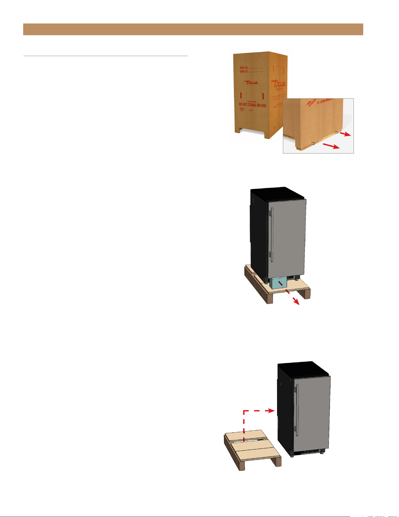
PROCEDURE
The following procedure is recommended for uncrating
the unit:
1. Remove the outer packaging (cardboard and clear
plastic). See fig. 1.
2. Inspect the unit for concealed damage. Immediately
file a claim with the freight carrier if there is damage.
3. Cut the plastic band and remove the foam block.
See fig. 2.
NOTE: MOVE THE UNIT AS CLOSE AS
POSSIBLE TO ITS FINAL LOCATION BEFORE
REMOVING THE SKID.
4. Position the floor protector next to the skid.
5. Carefully lift the unit off the skid and place the unit
on the floor protector. See fig. 3.
6. Remove the interior packaging.
INSTALLATION
FIG. 1.
Pull the staples from the skid.
FIG. 3.
Carefully move the unit off the skid.
FIG. 2.
Remove the foam block after moving the unit as
close as possible to the final installation location.
ADA HEIGHT 15" TRUE ICE
®
MACHINE INSTALL GUIDETEC_TM_157 REV. B EN
08/22/2022
Page 45 of 80
INSTALLATION
LEVELING LEGS
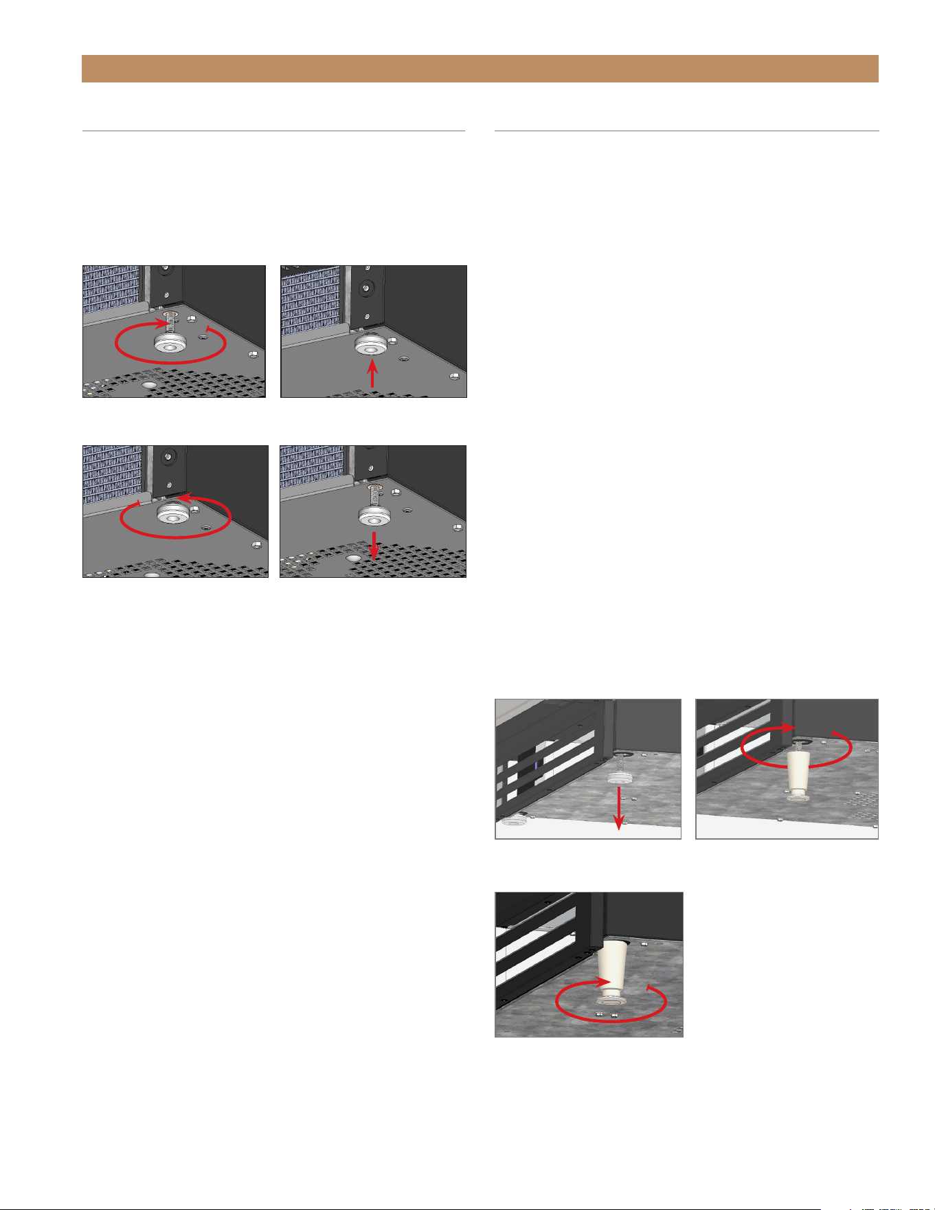
PROCEDURE
With access to the bottom of the cabinet, turn the
leveling legs to adjust the level as needed.
See figs. 1 and 2.
FIG. 1.
Turn the leveling legs clockwise to lower the unit.
FIG. 2.
Turn the leveling legs counterclockwise to raise the unit.
2-1/2" LEVELING LEGS
2-1/2" (64 mm) leveling legs raise the minimum height
of the unit to 33-3/4" (857.25 mm). The leveling
legs are adjustable up to 1" (25.4 mm), raising the
maximum height of the unit to 34-3/4" (882.7 mm). If
so desired, you can order a taller grill to hide the gap
caused by the 2-1/2" leveling legs. Please contact our
parts department at 844-849-6226 or
TrueResidentialParts@TrueMfg.com.
PROCEDURE
1. Access the bottom of the cabinet.
2. Remove the existing standard leveling legs.
See fig. 3.
3. Thread the new leveling legs into the bottom of
the cabinet. See fig. 4.
4. Verify the level of the cabinet. If the cabinet is
not level, gently lift and support the low end of
the cabinet. Then, adjust the bottom stem of the
leveling leg to level and support the cabinet.
See fig. 5.
FIG. 5.
Turn the bottom stem to
level the cabinet.
FIG. 3.
Remove the existing
leveling legs.
FIG. 4.
Screw in the leveling legs.
TRUE RESIDENTIAL
®
P#829074 TEC_TM_157 REV. B EN08/22/2022Page 46 of 80
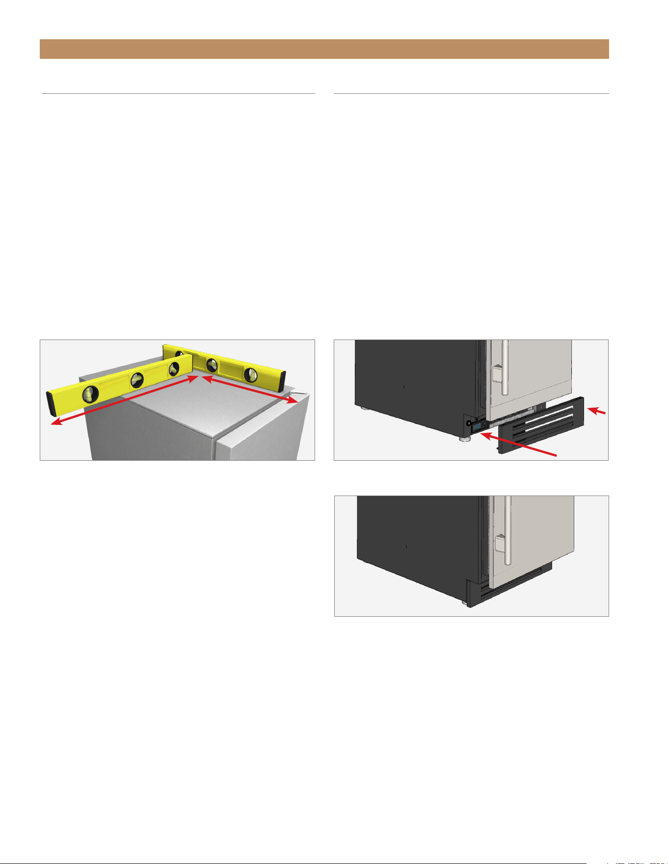
LEVELING
Proper leveling of your ice maker is critical to
operating success. Leveling effects drainage and door
operation.
PROCEDURE
1. Set the unit in its final location. Be sure there is
adequate ventilation in your room.
2. Verify the unit’s level. On the unit’s top, check the
level front-to-back and side-to-side. See fig. 1.
3. Turn the leveling legs as needed to adjust the
level. See “Leveling Legs" (page 45).
INSTALLATION
FIG. 1.
Check the level from the top of the unit.
FIG. 1.
Attach the kickplate to the magnets below the door.
FIG. 2.
Adjust the kickplate as needed.
KICKPLATE INSTALLATION
The kickplate is shipped unattached to the unit to
allow easy access for levelling. The kickplate attaches
to the unit with magnets at the bottom of the unit.
PROCEDURE
1. After leveling the unit, position the kickplate below
the door. See figs. 1 and 2.
2. Verify the kickplate is correctly aligned. Adjust
as needed.
REMOVAL
Pull the kickplate away from the unit.

ADA HEIGHT 15" TRUE ICE
®
MACHINE INSTALL GUIDETEC_TM_157 REV. B EN
08/22/2022
Page 47 of 80
CABINET SETUP
ICE SCOOP
90˚DOORSTOP INSTALLATION (OPTIONAL ACCESSORY)
PRESERVE THE MOMENT
®
TRUE RESIDENTIAL
®
P#829074 TEC_TM_157 REV. B EN08/22/2022Page 48 of 80
CABINET SETUP
ICE SCOOP
For easy storage, position the ice scoop on the door’s
interior. See fig. 1.
PROCEDURE
1. Orient the door as desired. See “Reversing Door".
(page 74).
2. Locate the ice scoop in the interior packaging.
3. Position the ice scoop on the door’s interior.
See fig. 1.
FIG. 1.
Attach the ice scoop to the door.
90° DOORSTOP INSTALLATION
(OPTIONAL ACCESSORY)
The doorstop restricts the door from opening past
approximately 90˚ to prevent damage to surrounding
cabinets.
NOTE: BE SURE TO PUT A DOORSTOP PIN IN BOTH
THE TOP AND BOTTOM HINGES. SEE FIGS. 1 AND 2.
FIG. 1.
Drop the doorstop pin into the articulated hinge.
FIG. 2.
Install a doorstop pin in both hinges.

ADA HEIGHT 15" TRUE ICE
®
MACHINE INSTALL GUIDETEC_TM_157 REV. B EN
08/22/2022
Page 49 of 80
CABINET OPERATION
BEFORE OPERATING
BREAKER RESET
POWER SEQUENCE
ICE MAKING SEQUENCE
ELECTRONIC CONTROL OPERATION
PRESERVE THE MOMENT
®
TRUE RESIDENTIAL
®
P#829074 TEC_TM_157 REV. B EN08/22/2022Page 50 of 80
CABINET OPERATION
BEFORE OPERATING
Before running the unit, verify the water shutters and
pump cap are correctly installed. Failure to do so can
cause incorrect operation. See "Interior Components"
on page 68.
To ensure ice quality, please clean and sanitize this
machine prior to first use. See “Descaling & Sanitizing"
(page 66). To ensure proper operation, follow the
installation checklist at the front of this manual.
NOTE: COSTS ASSOCIATED WITH
ADJUSTMENTS, CLEANING AND SANITIZING
PROCEDURES IN THIS GUIDE ARE NOT
COVERED BY THE WARRANTY.
WARNING! DO NOT USE THE ICE
MACHINE TO STORE ANYTHING
OTHER THAN ICE.
WARNING! DO NOT OPERATE
EQUIPMENT THAT HAS BEEN
MISUSED, NEGLECTED, DAMAGED,
ALTERED OR MODIFIED IN ANY WAY.
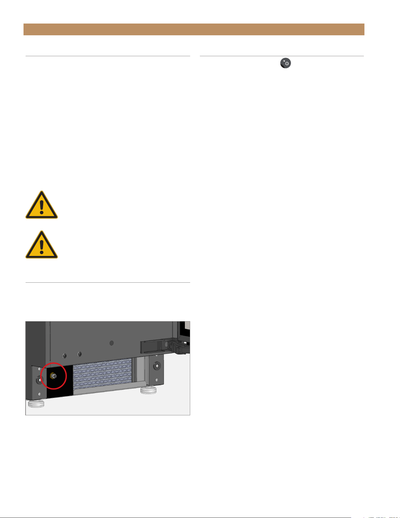
BREAKER RESET
The breaker switch is located behind the kickplate
(see fig. 1). If the unit trips, press the breaker to reset
the switch.
FIG. 1.
Breaker switch location.
POWER SEQUENCE
• Press the power button
once to begin ice
making operation. Press the button a second time
to turn the ice machine off.
• When unit is plugged in, the control board goes
through a sequence of checks to verify all sensors
are working properly.
• The drain system is energized when power is
supplied to the unit. It automatically turns on when
it senses water in the drain tube.
• Display will show oFF until the power button is pressed.
• If the unit powers the drain pump but the drain remains
clogged for five minutes, the display will show drn and
cut power to the unit.
• If unit is too cold / too hot, or if the temperature probe is
unplugged / failed, the unit shuts down and displays an
error message.

ADA HEIGHT 15" TRUE ICE
®
MACHINE INSTALL GUIDETEC_TM_157 REV. B EN
08/22/2022
Page 51 of 80
CABINET OPERATION
ICE MAKING SEQUENCE
Your TRUE Ice
®
machine will produce one batch of ice
(24 cubes) approximately every 20 minutes.
The following steps occur during ice making —
INITIAL FILL / INITIAL HARVEST
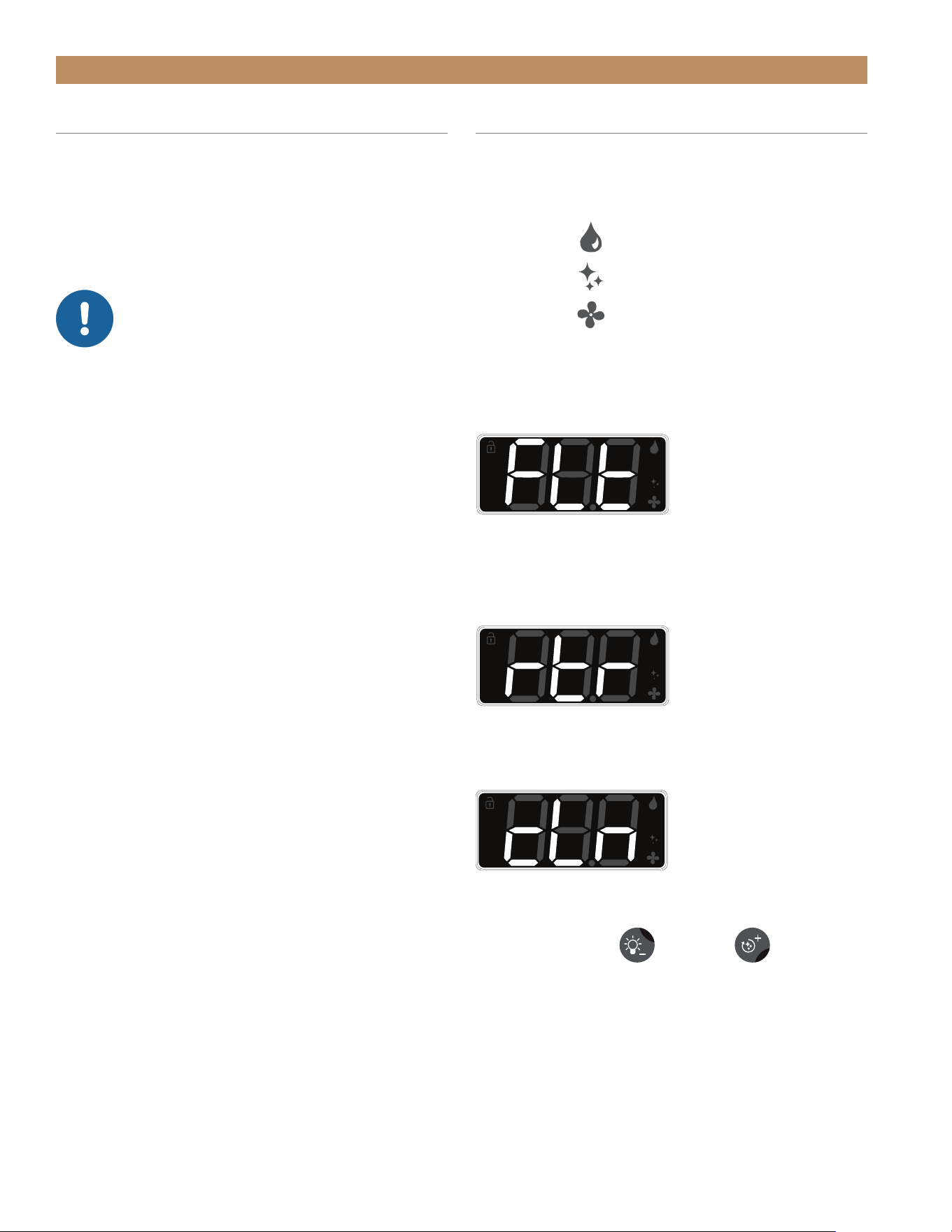
The ice machine always begins in Fill mode.
During Fill or Harvest modes —
• The display will read FiL (Fill mode) or hAr
(Harvest mode).
• The reservoir fills with water (for 2–3 minutes)
• Excess / residual water drains.
• Any residual ice cubes from a previous cycle are
melted free from the evaporator by warming the
evaporator with a warm refrigerant (Harvest mode).
ICE MAKING
When making ice —
• The display will read ICE
• Water sprays into the inverted ice cups as the
evaporator cools, forming ultra-clear ice cubes in
each cup
• The compressor, condenser fan motor, and water
pump operate.
• As ice is produced on the evaporator, the reservoir's
water level will lower.
• Adjusting the ice cube size alters the water level
needed for completing the cycle.
• The ice making cycle ends when
○ The reservoir's water level has dropped to a
sufficient level based on the ice cube size
setting OR
○ When the t1 evaporator probe detects the
minimum temperature threshold.
ICE HARVEST
When harvesting ice —
• The display will read hAr
• The compressor remains on, but the condenser fan
motor and pump turn off. The hot gas bypass and
water valves open.
• As the evaporator warms, ice cubes begin to fall
into the ice bin.
• The reservoir refills with water and overflows to
flush impurities down to the drain pump.
• The harvest cycle ends when the evaporator
reaches 47˚F (8.3˚C) and then a completion
timer expires.
• All 24 ice cubes should fall into the ice storage bin
before the next ice making cycle begins.
FULL BIN
When the ice bin is full —
• The display will read FUL
• The ice machine shuts off automatically when the
ice level sensor determines the amount of ice has
reached the set level.
• The condenser fan will turn on in reverse to clean
the condenser; this removes any built-up dust or
debris, which prolongs the time needed between
full condenser coil cleanings.
• The drain pump will periodically run to remove any
residual water in the bin from melted ice cubes.
• The ice machine turns back on when the ice level
sensor determines the amount of ice has decreased
to below the set level.
TRUE RESIDENTIAL
®
P#829074 TEC_TM_157 REV. B EN08/22/2022Page 52 of 80
CABINET OPERATION
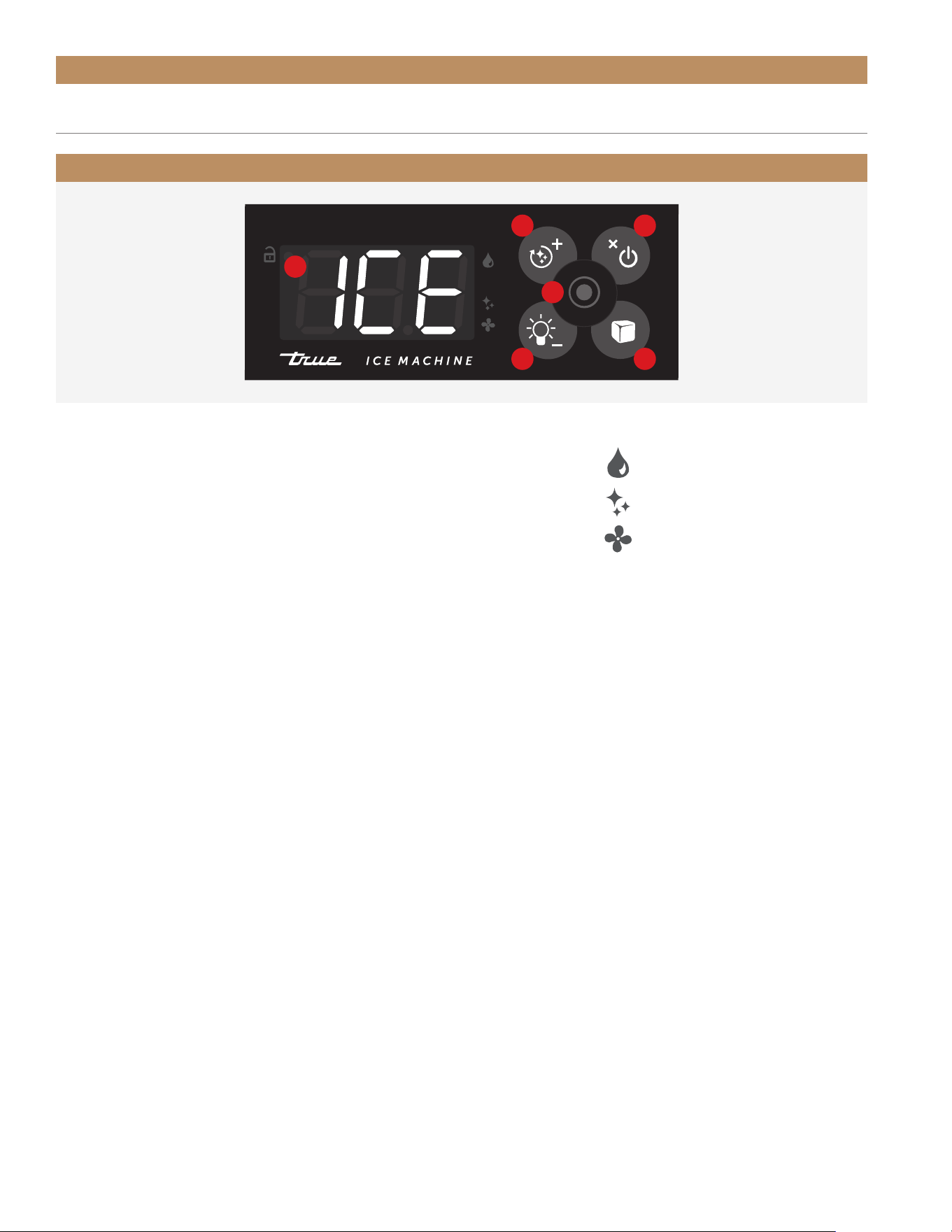
ELECTRONIC CONTROL OPERATION
ELECTRONIC CONTROL LEGEND
WATER FILTER REMINDER
CLEANING REMINDER
AIR FILTER REMINDER
A. DISPLAY
B. INITIATE AUTOMATIC CLEAN;
SCROLL UP (IN MENU MODE)
C. TOGGLES POWER/STANDBY;
BACK/RETURN
D. OKAY/ENTER
E. TOGGLES LIGHT/ CHANGE BIN
LIGHT COLORS; SCROLL DOWN
(IN MENU MODE)
F. ADJUST CUBE SIZE
A
B C
D
E
F
ADA HEIGHT 15" TRUE ICE
®
MACHINE INSTALL GUIDETEC_TM_157 REV. B EN
08/22/2022
Page 53 of 80
CABINET OPERATION
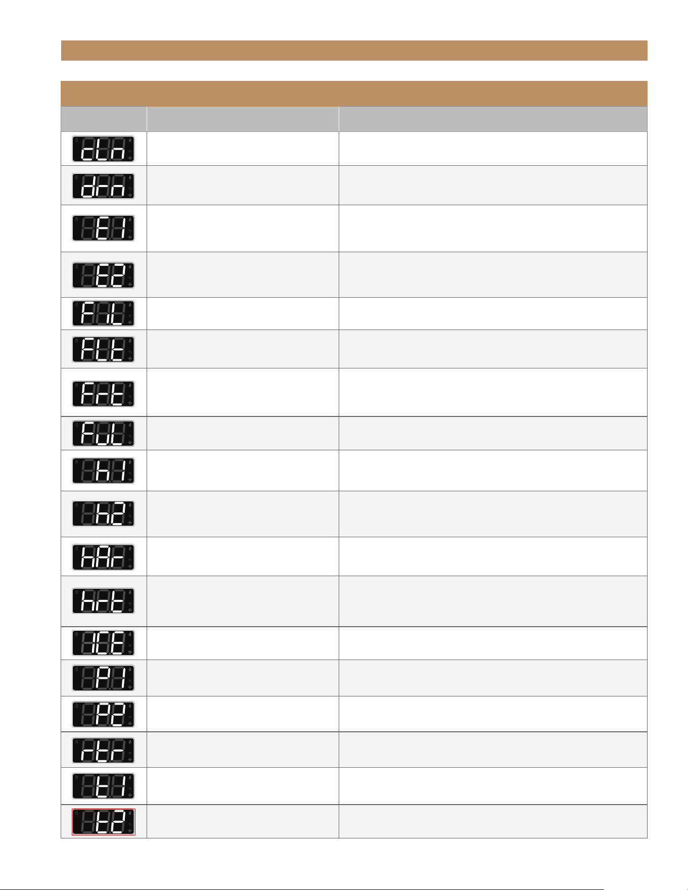
ELECTRONIC DISPLAY CODES
Display Definition Detailed Description
Clean cycle reminder
In Menu Mode: view the number days elapsed since the
automatic clean cycle was performed
Drain pump failure
Clogged or kinked drain line. Drain was not able to clear
within 5 minutes of running.
Thermistor 1 Failure
Thermistor 1 is located on the evaporator outlet tube and is
used for terminating the harvest. E1 means the probe has a
bad or loose connection.
Thermistor 2 Failure
Thermistor 2 is located on the condenser outlet tube and is
used for fan cycling. E2 means the probe has a bad or loose
connection.
Fill mode
Water fills the reservoir for 2-3 minutes
Condenser coil cleaning reminder
In Menu Mode: view the number of days elapsed since the
last condenser coil cleaning.
Freeze time
In Menu Mode: view the most recent freeze times in min-
utes. View history of five previous cycles:
-1 (most recent), -2, -3, -4, -5
Ice storage bin is full
Ice has reached the full level and the unit is in standby.
Water level sensor
In Menu Mode: h1 is the water level reading inside the
sump tank read in mm of H
2
O.
Ice level sensor
In Menu Mode: h2 is the ice level reading inside the ice
storage bin in cm.
Full = 35.0 and Empty = 55.0
Harvesting ice
Ice cubes drop in the storage bin and water fills the
reservoir for the next batch of ice.
Harvest time
In Menu Mode: view the most recent harvest times in min-
utes. View history of five previous cycles
-1 (most recent), -2, -3, -4, -5
Making ice
Circulation pump is running, machine sprays water into the
molds to make cubes.
High Pressure sensor (Optional)
In Menu Mode: P1 is the high side pressure transducer
taken at the compressor discharge read in PSI (lb/in
2
)
Low Pressure sensor (Optional)
In Menu Mode: P2 is the low side pressure transducer
taken at the compressor suction read in PSI (lb/in
2
)
Water filter reminder
In Menu Mode: view the number of days elapsed since the
last water filter replacement
Evaporator temperature
In Menu Mode: t1 is the evaporator outlet temperature read
in degrees Fahrenheit
Condenser temperature
In Menu Mode: t2 is the condenser outlet temperature read
in degrees Fahrenheit
TRUE RESIDENTIAL
®
P#829074 TEC_TM_157 REV. B EN08/22/2022Page 54 of 80
CABINET OPERATION
DRAIN TIME ALARM
If the drain does not clear within 5 minutes of
running, the display will show drn to signal a clogged /
kinked drain line or a drain pump failure. The control
automatically shut off the water supply.
If a clogged drain clears, the display will show drn
and oFF.
NOTICE! ADHERE TO LOCAL AND
STATE PLUMBING CODES.DO NOT
EXCEED THE MAXIMUM PLUMBING
HEIGHTS FOR THE GIVEN SETUP. SEE "DRAIN
CONNECTION" (PAGE 40). THE DRAIN ALARM
IS INITIATED BY THE CONTROL BOARD IN THE
EVENT OF IMPROPER DRAINAGE.
NOTE: VERIFY THE ICE MAKER DRAINS
THROUGH TWO CYCLES WITHOUT ANY ALARM
DURING INSTALLATION.
CONDENSER CLEANING REMINDER
Days elapsed since last condenser coil cleaning.
AUTOMATIC CLEANING REMINDER
Days elapsed since last performed automatic cleaning.
WATER FILTER REMINDER
Total time elapsed (shown in days) of water running
through the filter since the last water filter replacement.
MAINTENANCE REMINDERS
Your ice machine will remind you to clean, when to
perform the automatic clean, when to clean condenser
coil, and when to replace your water filter.
RESET REMINDERS
Press both the light and clean
buttons.
NOTE: RESETTING THE REMINDERS RESETS
BOTH THE CONDENSER CLEANING AND THE
WATER FILTER REPLACEMENT REMINDERS.
NOTE: THE AUTOMATIC CLEAN REMINDER
CAN ONLY BE RESET BY COMPLETING THE
AUTOMATIC CLEANING CYCLE.
Water Filter reminder
Cleaning reminder
Air Filter reminder
ADA HEIGHT 15" TRUE ICE
®
MACHINE INSTALL GUIDETEC_TM_157 REV. B EN
08/22/2022
Page 55 of 80
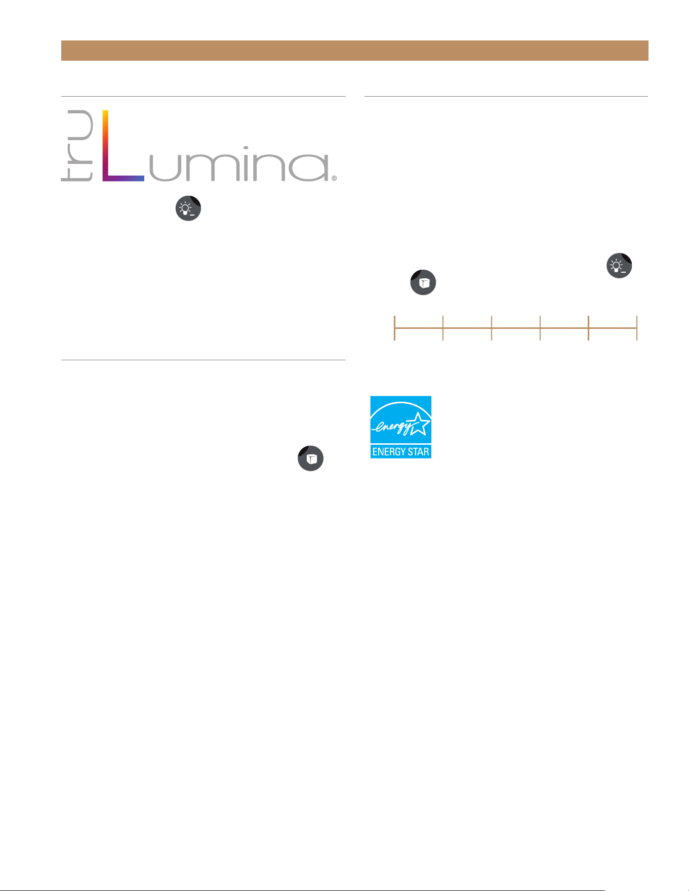
BIN LIGHT
Press the light button
to control the bin light.
• Press the light button repeatedly to cycle through
the 14 preset designer light colors
• Press and hold the light button for 5 seconds to
toggle the bin light on or off.
ADJUST CUBE SIZE
The ice cube size is easily adjustable to meet your
usage.
The available cube sizes range from -6 (smallest) to
+6 (largest). The default is 0.
To adjust the cube size, press the size button
until the display shows the desired setting.
CABINET OPERATION
FIG. 1.
Water quality setting range.
ADJUST FOR WATER QUALITY
The water quality setting allows your ice machine to
easily accommodate different levels of water quality /
hardness / scale. The available settings range from 0
(soft water / low scale) to 5 (hard water / high scale).
The default setting is 0. Please see fig. 1.
If you are unsure of your water quality, check your
water with a water quality test kit (not provided
by TRUE).
To adjust for water quality, press both the light
and size
buttons.
0
Soft water/
low scale
5
Hard water/
high scale
1 2 3 4
TRUE RESIDENTIAL
®
P#829074 TEC_TM_157 REV. B EN08/22/2022Page 56 of 80
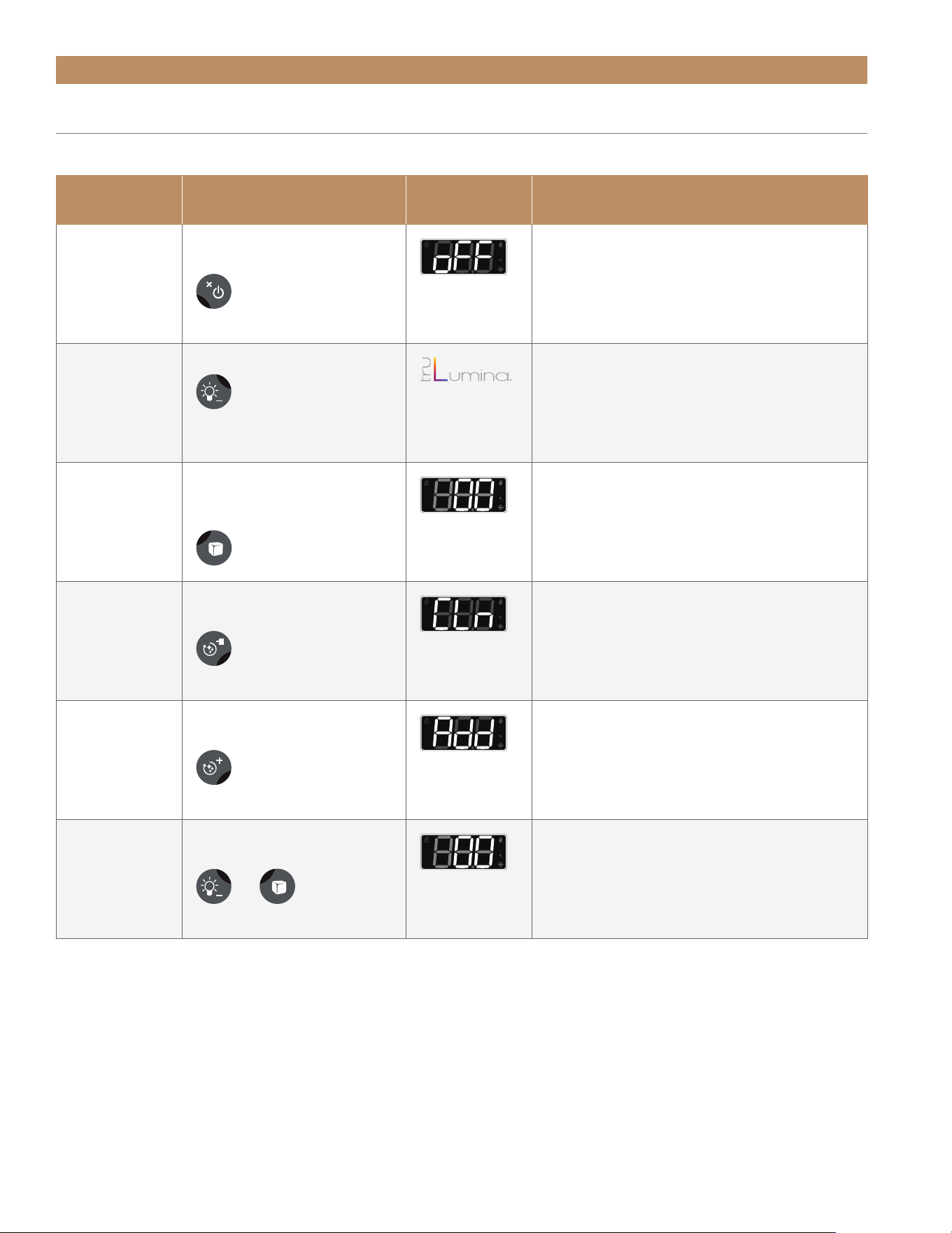
Command Key Combination Display Code Detailed Description
Power unit
on / off
Press and hold the power
button for 3 seconds
Turns the unit on and off.
Change light
color
Press the light button Switch between the 14 LED colors.
Adjust cube
size
Press the size button until
the display shows the de-
sired setting
Adjusts cube size in increments from 1 to
6 for larger cubes, then -6 to -1 for smaller
cubes.
Ice Size default is 0.
Clean Mode Press and hold the clean
button for 3 seconds
Press and hold Clean for 3 seconds to begin
(or end) the automatic cycle. Follow the
prompts to select the settings and start the
cycle.
Add cleaning
chemicals
After adding cleaning chemi-
cals, press the clean button
In Clean Mode, the "Add" notification notifies
when to add cleaners to the sump tank. Once
complete, push any button to continue the
automatic cycle.
Adjust for wa-
ter quality
Press both the light and the
size buttons
+
Soft water / low scale setting is 0. Hard water
/ high scale setting is 5. Adjusting the value
higher flushes more water between cycles,
resulting in clearer ice cubes.
CABINET OPERATION
COMMANDS AND KEY COMBINATIONS
See the table below for commands and their corresponding key combinations.
ADA HEIGHT 15" TRUE ICE
®
MACHINE INSTALL GUIDETEC_TM_157 REV. B EN
08/22/2022
Page 57 of 80
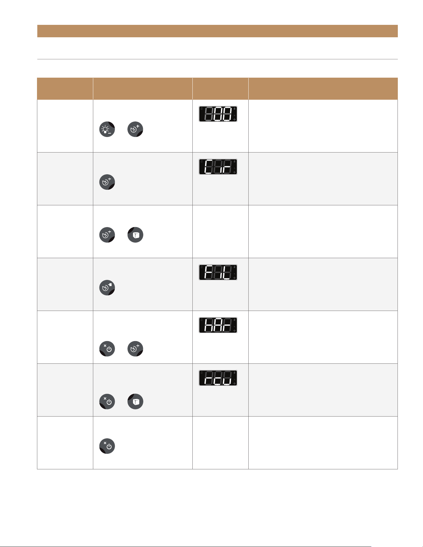
Command Key Combination Display Code Detailed Description
Reset
maintenance
reminders
Press both the light and the
clean buttons.
+
Resets the condenser cleaning and water
filter replacement reminders. Both are reset
when pressed. See "Maintenance Reminders"
(page 53).
Circulate pump
motor
Press the clean button
2 times.
In Standby: Circulates the Pump motor
(on / off).
Initiate manual
drain pump
operation
Press and hold both the
clean and size buttons.
+
n/a Bypasses the background operations and runs
the drain pump only while buttons are held.
Initiate manual
fill
Press the clean button
3 times.
In Standby: Starts a Manual Fill Routine.
Initiate manual
harvest
Press and hold the power
and the clean buttons for
3 seconds.
+
In Standby of Freeze: Starts a Manual
Harvest Cycle.
Initiate reverse
condenser
cleaning
Press and hold the power
and the size buttons for
3 seconds.
+
In Standby: Starts a Reverse Condenser
Cleaning.
Clear the
alarm history
Press the power button
2 times.
n/a Removes any alarms from the machine's
memory.
COMMANDS AND KEY COMBINATIONS
See the table below for commands and their corresponding key combinations.
CABINET OPERATION

TRUE RESIDENTIAL
®
P#829074 TEC_TM_157 REV. B EN08/22/2022Page 58 of 80
NOTES

ADA HEIGHT 15" TRUE ICE
®
MACHINE INSTALL GUIDETEC_TM_157 REV. B EN
08/22/2022
Page 59 of 80
GENERAL MAINTENANCE
WATER FILTER REPLACEMENT
CONDENSER COIL CLEANING
STAINLESS STEEL EQUIPMENT CARE AND CLEANING
DESCALING & SANITIZING
INTERIOR COMPONENTS
WINTERIZING
MAINTENANCE, CARE & CLEANING
PRESERVE THE MOMENT
®
TRUE RESIDENTIAL
®
P#829074 TEC_TM_157 REV. B EN08/22/2022Page 60 of 80
MAINTENANCE, CARE & CLEANING
GENERAL MAINTENANCE
You are responsible for maintaining the ice machine
in accordance with the instructions in this manual.
Maintenance procedures are not covered by warranty.
True recommends performing the following
maintenance procedures a minimum of once every six
months to ensure reliable, trouble-free operation.
WARNING! IF YOU DO NOT
UNDERSTAND THE NECESSARY
PROCEDURES OR SAFETY
PRECAUTIONS, CALL YOUR LOCAL
TRUE SERVICE REPRESENTATIVE TO PERFORM
MAINTENANCE PROCEDURES FOR YOU.
CAUTION! TAKE CARE DURING
OPERATION, MAINTENANCE, OR
REPAIRS TO AVOID CUTS OR
PINCHING FROM ANY CABINET
PART/COMPONENT.
EXTERIOR CLEANING
Clean the exterior as needed. Follow stainless steel
cleaning recommendations (page 64) to ensure your
machine always looks like new.
DESCALING & SANITIZING
Descale and sanitize every 6 months. See "Descaling
& Sanitizing" (page 66).
WATER FILTER REPLACEMENT
Replace the water filter at least once every 12 months.
More frequent replacement may be required based
on your water quality. See "Water Filter Replacement"
(page 61).
CONDENSER CLEANING
For optimum operation, clean your condenser coil
every 6 months. See "Condenser Coil Cleaning"
(page 62).
MAINTENANCE WEEKLY SEMI-ANNUAL ANNUAL
AFTER
PROLONGED
SHUTDOWN
AT START-UP
CLEAN CABINET
EXTERIOR
X X X
SANITIZE ICE
MACHINE
X X X X
DESCALE ICE
MACHINE
X X X X
CLEAN
CONDENSER COIL
X X X
CHANGE THE
WATER FILTER
X X X
CHECK ICE
QUALITY
X X X X X
ADA HEIGHT 15" TRUE ICE
®
MACHINE INSTALL GUIDETEC_TM_157 REV. B EN
08/22/2022
Page 61 of 80
MAINTENANCE, CARE & CLEANING
WATER FILTER REPLACEMENT
To order a replacement water filter, go to www.store.
trueresidential.com/collections/maintenance-1 or
contact our parts department at 844-849-6226 or
TrueResidentialParts@TrueMfg.com.
NOTE: BE SURE TO RESET THE WATER FILTER
REPLACEMENT REMINDER AFTER REPLACING
THE WATER FILTER. SEE "MAINTENANCE
REMINDERS" (PAGE 53).
NOTICE! TRUE RECOMMENDS
TURNING OFF THE WATER SUPPLY
BEFORE REPLACING THE WATER
FILTER TO PREVENT WATER FILTER
DAMAGE OR LEAKS.
NOTICE! DO NOT INSTALL THE
WATER FILTER WHILE THE WATER
SUPPLY IS PRESSURIZED. ALWAYS
RELIEVE THE WATER PRESSURE
BEFORE CHANGING THE FILTER.
PROCEDURE
1. Relieve the water pressure.
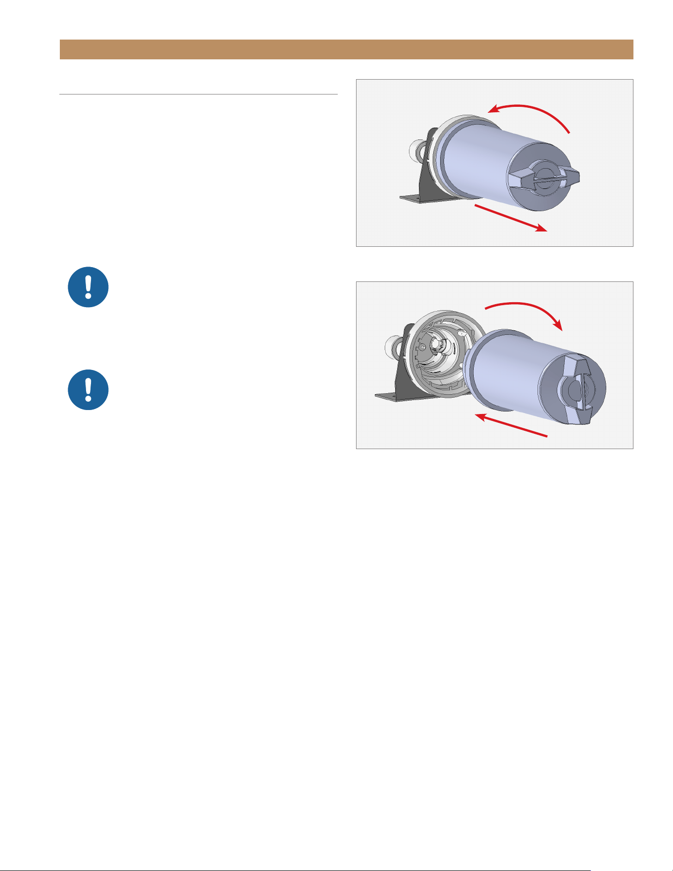
2. Rotate the water filter counterclockwise and pull
the filter from the unit. See fig. 1.
3. Apply the provided lubricant to the replacement
water filter o-rings.
4. Insert the replacement water filter and rotate the
filter clockwise. See fig. 2.
NOTE: BE SURE TO RESET THE WATER
FILTER REPLACEMENT REMINDER AFTER
REPLACING THE WATER FILTER. SEE
"MAINTENANCE REMINDERS" (PAGE 54).
FIG. 1.
Rotate the existing water filter counterclockwise and pull.
FIG. 2.
Insert the replacement water filter and rotate it clockwise.
TRUE RESIDENTIAL
®
P#829074 TEC_TM_157 REV. B EN08/22/2022Page 62 of 80
MAINTENANCE, CARE & CLEANING
CONDENSER COIL CLEANING
Keeping the condenser coil clean minimizes required
servicing and lowers electrical cost. Warranty does not
cover cleaning the condenser coil.
NOTE: BE SURE TO RESET THE CONDENSER
COIL CLEANING REMINDER AFTER CLEANING
THE CONDENSER COIL. SEE "MAINTENANCE
REMINDERS" (PAGE 54).
WARNING – Electrical shock or burn
hazard. Unplug the unit or turn off the
power supply before proceeding. DO NOT
clean appliance with a pressure washer or
hose.
ATTENTION – Risque d’électrocution ou
de brûlure. Débranchez l’appareil ou
coupez l’alimentation électrique avant de
continuer. Ne nettoyez pas l’appareil avec
un nettoyeur haute pression ou un tuyau.
CAUTION – Risk of eye injury from debris.
Eye protection is recommended.
ATTENTION – Les ailettes sont coupantes.
Soyez prudent pour éviter les lésions
oculaires. Une protection des yeux est
recommandée.
CAUTION – Coil fins are sharp. Gloves are
recommended.
ATTENTION – Les ailettes de la bobine
sont tranchantes. Les gants sont
recommandés.
REQUIRED TOOLS
Required tools include (but may not be limited to) the
following.
PROCEDURE
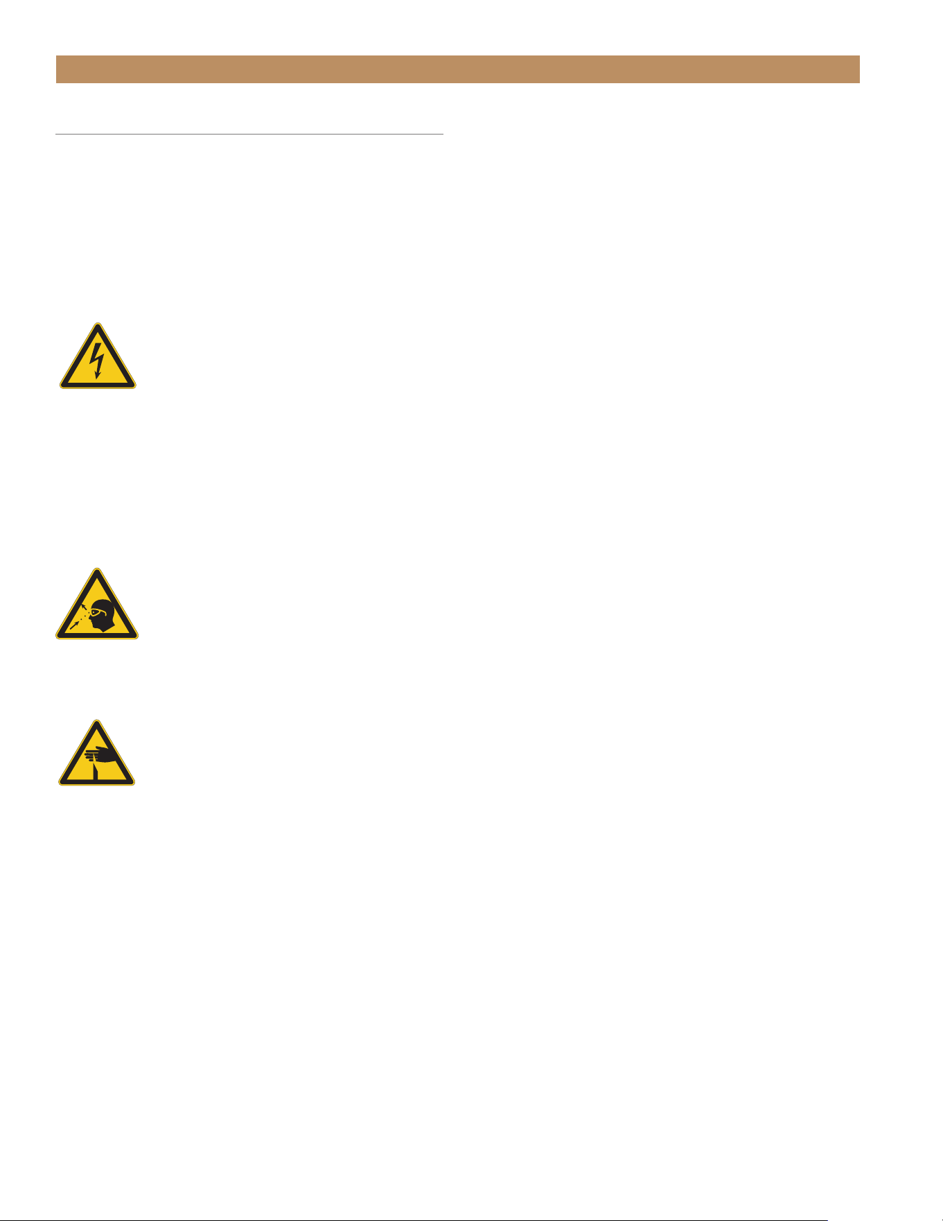
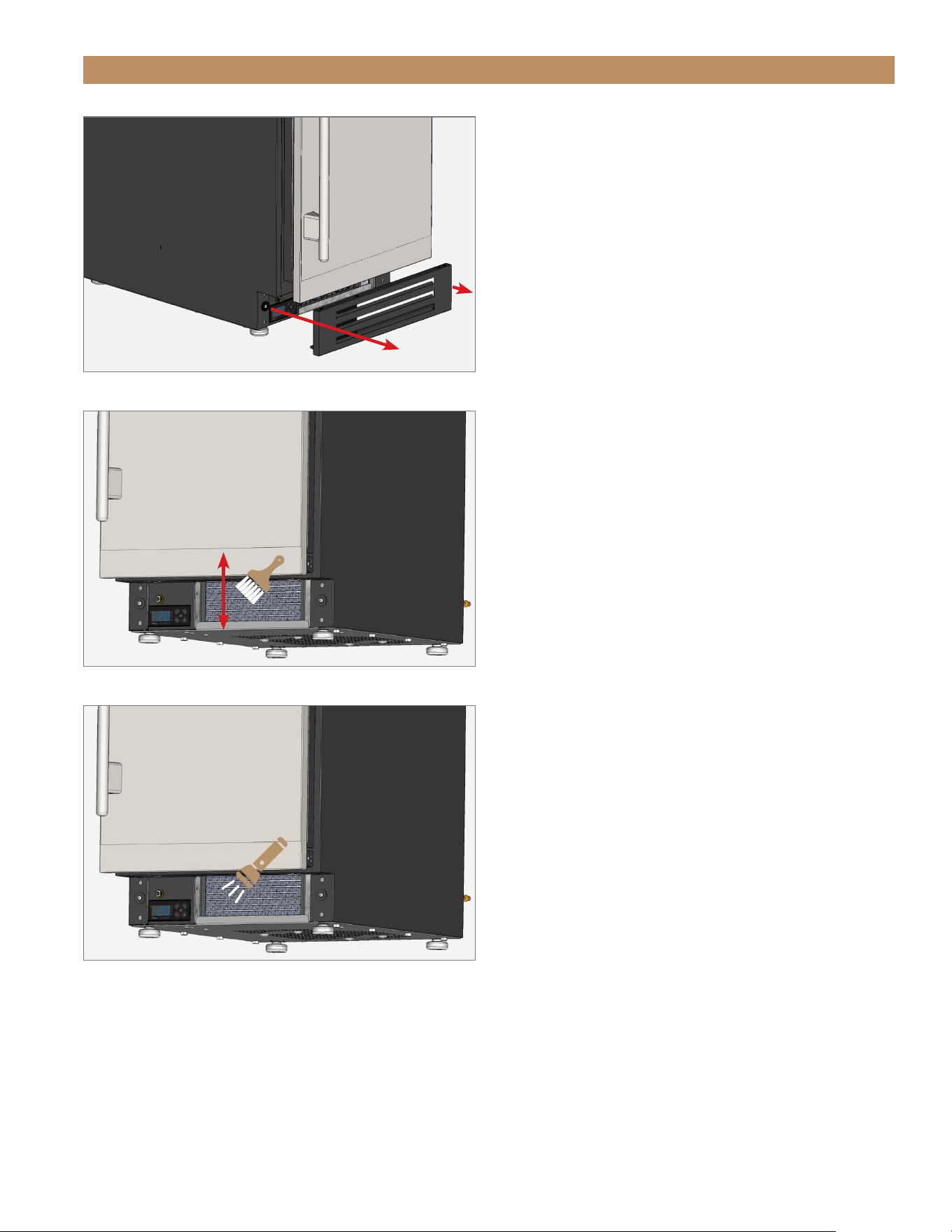
1. Remove the kickplate. See fig. 1.
2. With a stiff bristle brush, carefully clean
accumulated dirt from the front coil fins.
3. With the dirt removed from the surface of the coil,
use a flashlight to verify you can see through the
coil and observe the condenser fan blade spinning.
See fig. 3.
4. If the view is clear, reinstall the kickplate, restore
power, and verify correct operation.
5. If the view is not clear, gently blow compressed air
or CO
2
through the coil until it is clean.
6. Carefully vacuum any dirt around the condensing
unit area.
7. Reinstall the kickplate, restore power, and verify
correct operation.
• Gloves
• Eye Protection
• Stiff Bristle Brush
• Vacuum Cleaner
• Flashlight
• Tank of Compressed Air
ADA HEIGHT 15" TRUE ICE
®
MACHINE INSTALL GUIDETEC_TM_157 REV. B EN
08/22/2022
Page 63 of 80
FIG. 1.
Pull the kickplate off the magnets.
FIG. 2.
Never brush across the coil fins.
FIG. 3.
Verify all blockages have been removed.
MAINTENANCE, CARE & CLEANING

TRUE RESIDENTIAL
®
P#829074 TEC_TM_157 REV. B EN08/22/2022Page 64 of 80
MAINTENANCE, CARE & CLEANING
NOTICE! DO NOT USE ANY STEEL
WOOL, ABRASIVE OR CHLORINE
BASED PRODUCTS TO CLEAN
STAINLESS STEEL SURFACES.
STAINLESS STEEL OPPONENTS
There are three basic things which can break down
your stainless steel’s passivity layer and allow corrosion
to rear its ugly head.
• Scratches from wire brushes, scrapers, and steel
pads are just a few examples of items that can be
abrasive to stainless steel’s surface.
• Deposits left on your stainless steel can leave spots.
You may have hard or soft water depending on what
part of the country you live in. Hard water can leave
spots. Hard water that is heated can leave deposits
if left to sit too long. These deposits can cause the
passive layer to break down and rust your stainless
steel. All deposits left from food prep or service
should be removed as soon as possible.
• Chlorides are present in table salt, food, and water.
Household and industrial cleaners are the worst
type of chlorides to use.
STAINLESS STEEL EQUIPMENT CARE & CLEANING
STAINLESS STEEL CLEANING & RESTORATION
Do not use stainless steel cleaners or similar solvents
to clean plastic or powder-coated parts. Instead, use
warm soapy water.
• For routine cleaning and removal of grease and
oil, apply white vinegar, ammonia, or any good
commercial detergent* with a soft cloth or sponge.
• Stainless steel polish (i.e., Zep
®
Stainless Steel
Polish, Weiman
®
Stainless Steel Cleaner & Polish,
Nyco
®
Stainless Steel Cleaner & Polish, or Ecolab
®
Ecoshine
®
) and olive oil can act as a barrier against
fingerprints and smears.
• Degreasers* (i.e., Easy-Off
®
Specialty Kitchen
Degreaser or Simple Green
®
Industrial Cleaner &
Degreaser) are excellent for removal of grease, fatty
acids, blood and burnt-on foods on all surfaces.
• For restoration/passivation or removing stubborn
stains and discoloration, Brillo
®
Cameo
®
, Zud
®
Cleanser, Ecolab
®
Specifax
™
First Impression
®
Metal Polish, Sheila Shine, or talc can be applied
by rubbing in the direction of the polish lines.
* Do not use detergents or degreasers with chlorides
or phosphates.
NOTE: THE USE OF PROPRIETARY NAMES IS
INTENDED FOR EXAMPLE ONLY AND DOES NOT
CONSTITUTE OR IMPLY AN ENDORSEMENT.
OMISSION OF PROPRIETARY CLEANSERS FROM
THIS LIST DOES NOT IMPLY INADEQUACY.

ADA HEIGHT 15" TRUE ICE
®
MACHINE INSTALL GUIDETEC_TM_157 REV. B EN
08/22/2022
Page 65 of 80
MAINTENANCE, CARE & CLEANING
• Maintain the Cleanliness of Your Equipment – Avoid
build-up of hard stains by cleaning frequently. Use
cleaners at the recommended strength (alkaline
chlorinated or non-chloride).
• Use the Correct Cleaning Tools – Use non-abrasive
tools when cleaning your stainless steel products.
The stainless steel’s passive layer will not be
harmed by soft cloths and plastic scouring pads.
• Clean Along Polishing Lines – Polishing lines ("grain")
are visible on some stainless steels. Always scrub
parallel to polishing lines when visible. Use a plastic
scouring pad or soft cloth when you cannot see the
grain.
• Use Alkaline, Alkaline-Chlorinated or Non-Chloride
Cleaners – While many traditional cleaners are
loaded with chlorides, the industry is providing an
ever increasing choice of non-chloride cleaners. If
you are not sure of your cleaner’s chloride content,
contact your cleaner supplier. If they tell you that
your present cleaner contains chlorides, ask if
they have an alternative. Avoid cleaners containing
quaternary salts, as they can attack stainless steel,
causing pitting and rusting.
• Rinse – When using chlorinated cleaners, you must
rinse and wipe dry immediately. It is better to wipe
standing cleaning agents and water as soon as
possible. Allow the stainless steel equipment to air
dry. Oxygen helps maintain the passivity film on
stainless steel.
• Never Use Hydrochloric Acid (Muriatic Acid) on
Stainless Steel – Even diluted, hydrochloric acid
can cause corrosion, pitting and stress corrosion
cracking of stainless steel.
• Water Treatment – To reduce deposits, soften hard
water when possible. Installation of certain filters
can remove corrosive and distasteful elements.
Salts in a properly maintained water softener can
also be to your advantage. Contact a treatment
specialist if you are not sure of the proper water
treatment.
• Regularly Restore & Passivate Stainless Steel –
Stainless steel gets its stainless properties from the
protective chromium oxides on its surface. If these
oxides are removed by scouring, or by reaction
with harmful chemicals, then the iron in the steel
is exposed and can begin to oxidize, or rust.
Passivation is a chemical process that removes
free iron and other contaminants from the surface
of stainless steel, allowing the protective chromium
oxides to re-form.
8 TIPS TO HELP PREVENT RUST ON STAINLESS STEEL
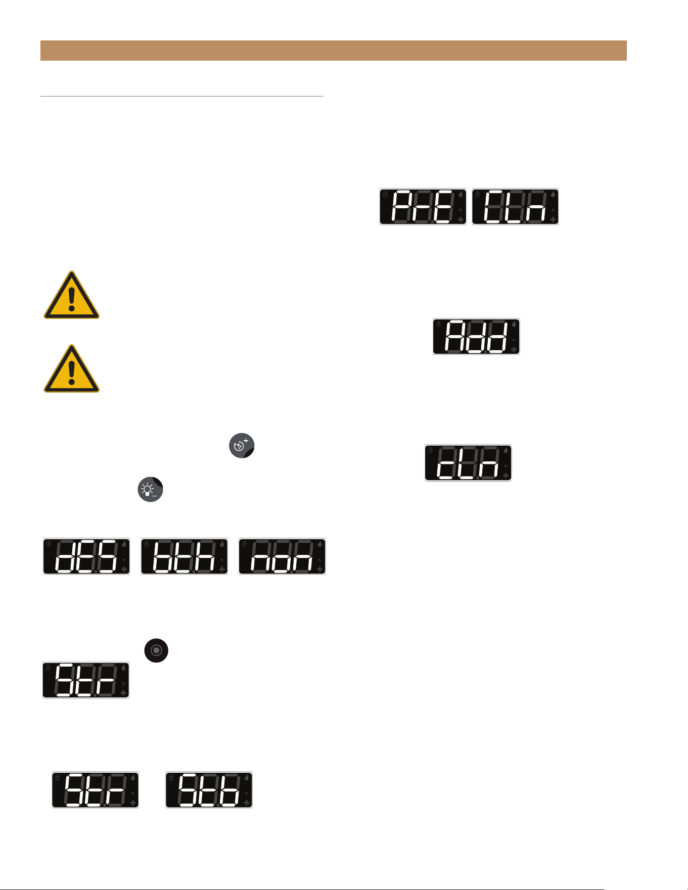
TRUE RESIDENTIAL
®
P#829074 TEC_TM_157 REV. B EN08/22/2022Page 66 of 80
MAINTENANCE, CARE & CLEANING
DESCALING & SANITIZING
You should fully descale your ice machine every 6
months. Descaling also involves removing key ice
machine parts and rinsing them and the inside of the
machine with ice machine descaler.
Sanitizing the ice machine removes potential biological
contaminations and molding. The sanitation process
is identical to the descaling process, except that a
sanitizing agent is used in place of the descaling
chemicals.
WARNING! WEAR RUBBER GLOVES
AND EYE PROTECTION WHEN
HANDLING ICE MACHINE DESCALER
OR SANITIZER.
CAUTION! DO NOT COMBINE
DESCALER AND SANITIZER.
DESCALING PROCEDURE
1. Press and hold the clean button
for 3
seconds. The display will show dES.
2. Press the light
and / or the clean button until
the display shows dES (descale only) or bth (both
descale and sanitize), or non (none)
3. With the display showing the desired cycle, press
the okay button
. The display will show Str.
4. Press the light and / or the clean button until
the display shows either Str or Stb (standby).
This determines the ice machine's action upon
completion of the selected cleaning cycle.
5. With the display showing the desired action, press
the okay button. The selected cleaning cycle will
begin.
6. The display will alternate between PrE and CLn
(preclean) for approximately 3 minutes.
7. When the display shows Add, pour 6 fl. oz. of
undiluted True Ice
TM
Machine Descaler into the
spray compartment behind the water shutters.
8. After adding the descaler, press the okay button.
The automatic cycle will continue.
9. Wait for the rinse and drain cycles to complete
(30 minutes). For light descaling, proceed to
step 14.
10. Remove the ice guide, water shutters, spray
bar and pump clean-out cap. See "Interior
Components" (page 67).
11. Mix a descaling solution of 10 fl. oz. undiluted
True Ice
TM
Machine Descaler and 1 gal. of water.
12. With approximately half the descaling solution,
clean the removed parts with a brush; then soak
them for 20 minutes.
13. With the remaining solution, descale the ice
bin, door, door gasket, spray compartment, and
evaporator.
14. Rinse all parts with clean water.
Run descale
cycle only
Run both descale
and sanitize cycles
Exit descale and
sanitize menu
Machine will begin
ice making sequence
Machine will
enter standby
Preclean stage
Add cleaning
chemicals
While running the
automatic clean cycle
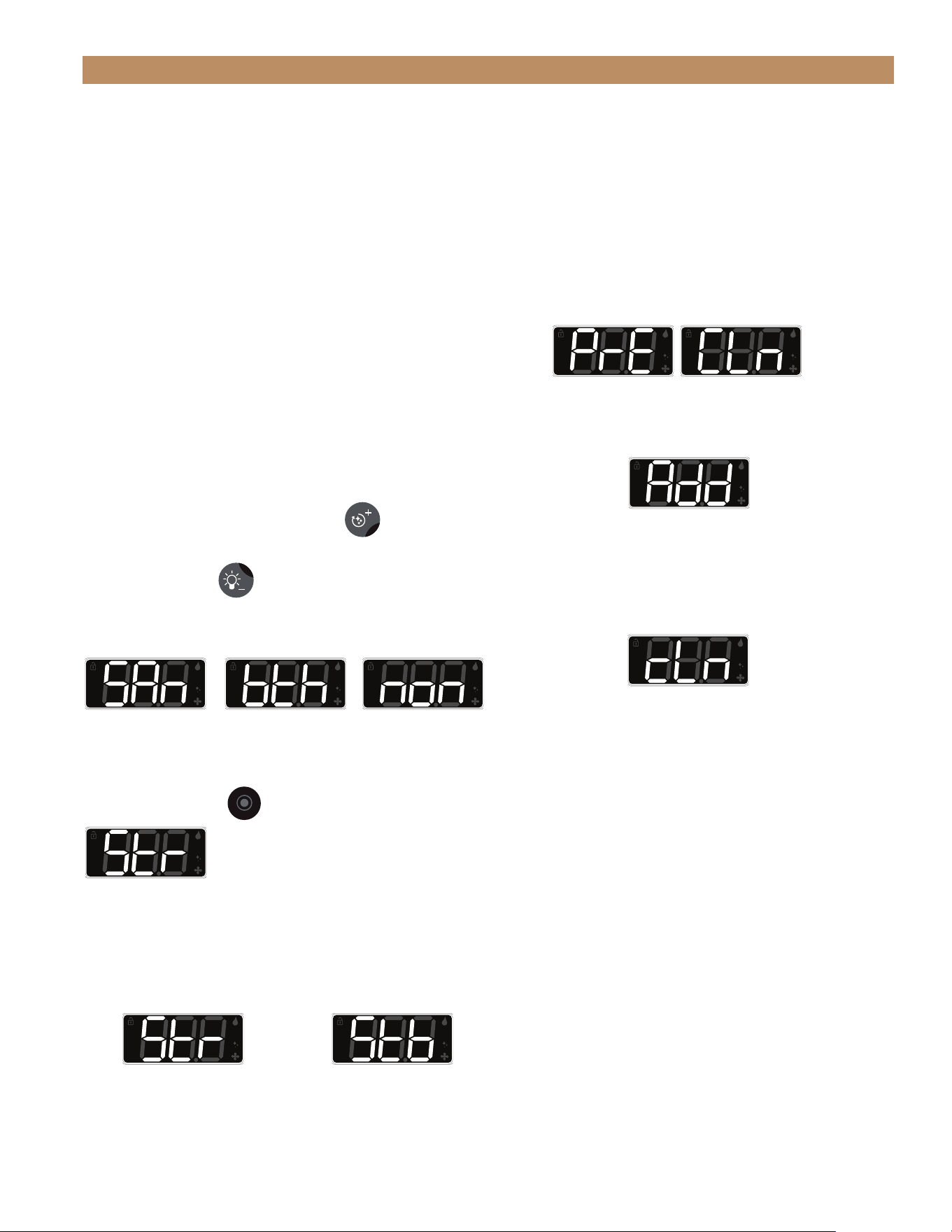
ADA HEIGHT 15" TRUE ICE
®
MACHINE INSTALL GUIDETEC_TM_157 REV. B EN
08/22/2022
Page 67 of 80
MAINTENANCE, CARE & CLEANING
SANITIZING PROCEDURE
1. Remove the ice guide, water supply, spray bar and
pump clean-out cap. See "Interior Components"
(page 67).
2. Mix 1.5 fluid ounces (3 tbsp) of 5.25% hypochlorite
solution (chlorine bleach) with 3 gallons of warm
water.
3. Use 1/2 of the solution to sanitize the removed
parts. Soak the parts in the solution. DO NOT RINSE
THE PARTS AFTER SANITIZING.
4. With the remaining solution, sanitize the interior
surfaces of the machine and the bin. DO NOT RINSE
THE SANITIZED AREAS.
5. Reinstall the components.
6. Press and hold the clean button
for 3
seconds. The display will show dES.
7. Press the light
and / or the clean button until
the display shows SAn (descale only) or bth (both
descale and sanitize), or non (none)
8. With the display showing the desired cycle, press
the okay button
. The display will show Str.
9. Press the LIGHT and / or the CLEAN button until the
display shows either Str (startup) or Stb (standby).
This determines the ice machine's action upon
completion of the selected cleaning cycle.
Run Sanitize
cycle only
Run both descale
and sanitize cycles
Machine will begin
ice making sequence
Machine will
enter standby
10. With the display showing the desired action,
press the okay button. The selected cleaning cycle
will begin.
11. The display will alternate between PrE and CLn
(preclean) for approximately 3 minutes.
12. When the display shows Add, pour 2 teaspoons of
5.25% hypochlorite solution (chlorine bleach) into
the spray compartment behind the water shutters.
13. After adding the sanitizer solution, press the okay
button. The automatic cycle will continue.
14. Wait for the sanitizing cycle to finish. Immediately
rinse off and dry any exterior areas where
sanitizing solution may have spilled.
Add cleaning
chemicals
Preclean stage
While running the
automatic clean cycle
Exit descale and
sanitize menu
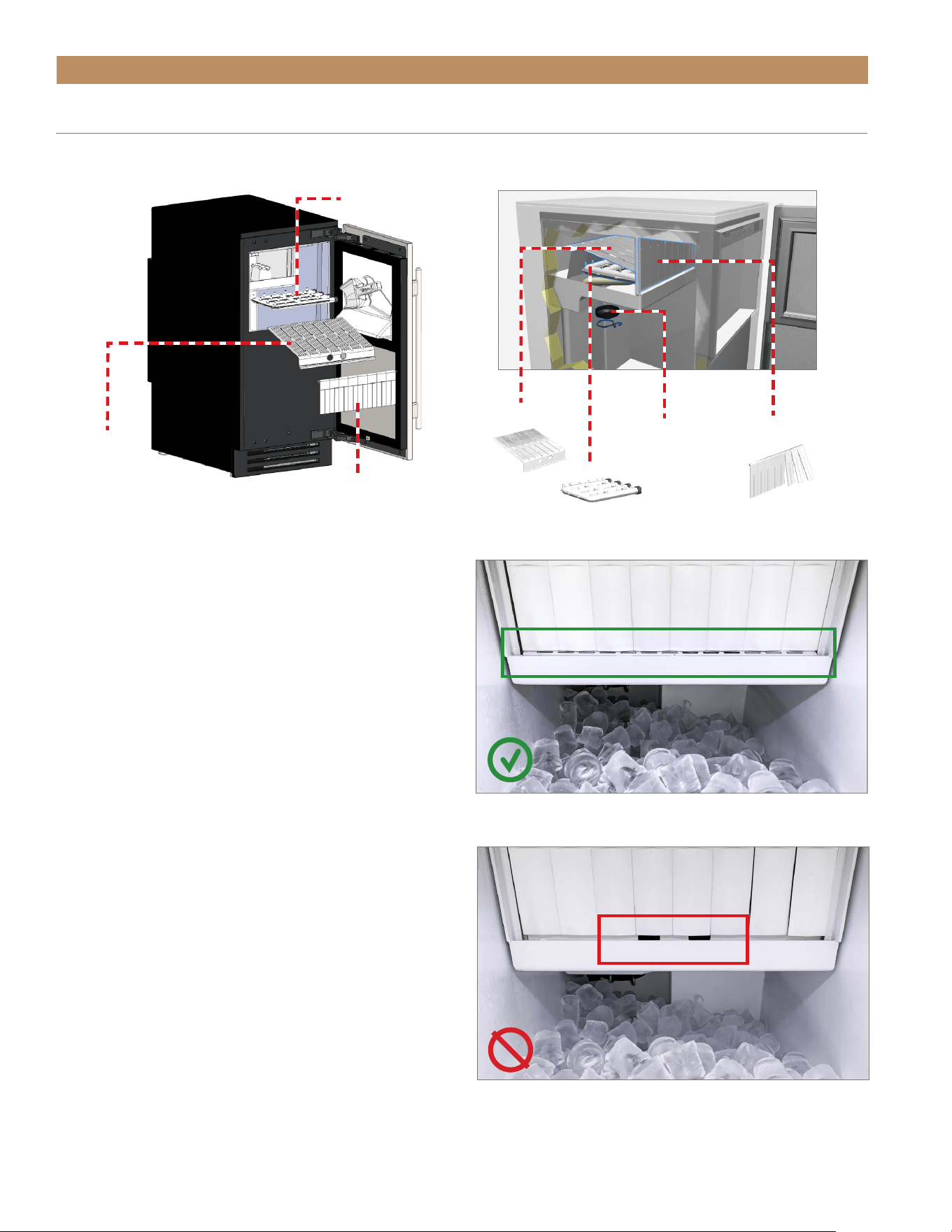
TRUE RESIDENTIAL
®
P#829074 TEC_TM_157 REV. B EN08/22/2022Page 68 of 80
MAINTENANCE, CARE & CLEANING
SPRAY BAR
SPRAY BAR
WATER
SHUTTERS
WATER
SHUTTERS
ICE GUIDE
ICE GUIDE
PUMP CLEAN-OUT CAP
WATER SHUTTER
The water shutter hangs in front of the spray bar and
ice guide. It prevents spraying water from escaping the
evaporator compartment.
REMOVAL
Lift the shutter rod's ends from the recesses in the
sidewall.
INSTALLATION PROCEDURE
Insert the shutter rod's ends into the recesses in the
sidewall. To be correctly installed, the water shutter
must–
• Hang from a shutter rod fully seated in the recessed
end supports.
• Conceal the ice guide finger holes.
CORRECT.
Ice guide finger holes are hidden; ice guide slotted holes are
visible.
INCORRECT.
Ice guide finger holes are visible.
INTERIOR COMPONENTS
See the following for the removal and correct installation of the interior components.
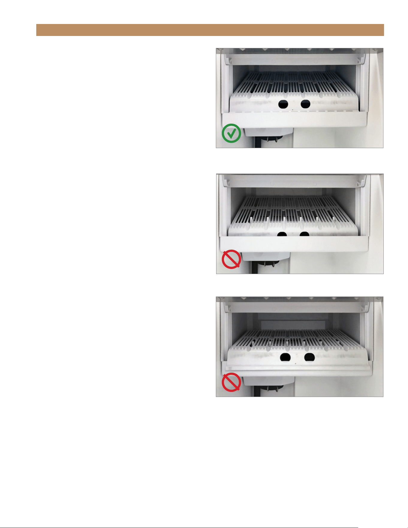
ADA HEIGHT 15" TRUE ICE
®
MACHINE INSTALL GUIDETEC_TM_157 REV. B EN
08/22/2022
Page 69 of 80
MAINTENANCE, CARE & CLEANING
CORRECT.
Ice guide positioned in the guide channel and flush against the
back side of the water trough opening.
INCORRECT.
Ice guide positioned too far inside the water trough.
INCORRECT.
Ice guide positioned outside the water trough.
ICE GUIDE
The ice guide sits over the spray nozzles and directs
falling ice into the bin.
REMOVAL
Lift the front of the guide and pull the guide forward.
INSTALLATION PROCEDURE
Position the ice guide over the spray bar. To be
correctly installed, the ice guide must–
• Be firmly positioned over the spray bar.
• Sit with its front edge inside the water trough.
• Have its slots aligned with the spray nozzles.
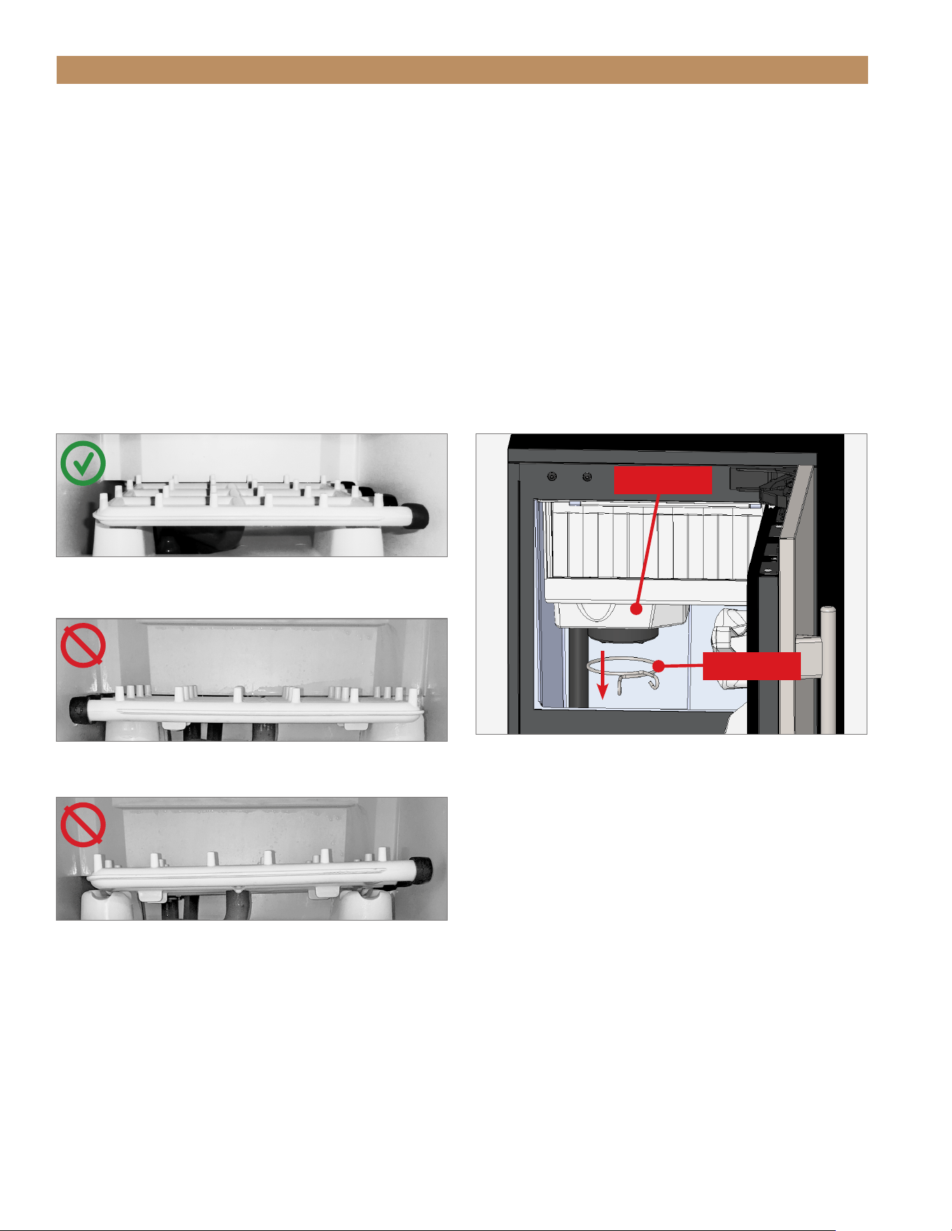
TRUE RESIDENTIAL
®
P#829074 TEC_TM_157 REV. B EN08/22/2022Page 70 of 80
SPRAY BAR
REMOVAL
Carefully pull the spray bar from the water supply
hose.
INSTALLATION PROCEDURE
The spray bar, located in the water trough, supplies
water to the individual ice cube cups. To be correctly
installed, the spray bar must–
• Be positioned with the clean-out caps on the right.
• Sit fully seated and horizontally level.
CORRECT.
Spray bar is fully seated, level, and positioned with the clean-
out caps on the right..
INCORRECT.
Spray bar is not fully seated or level.
INCORRECT.
Spray bar positioned with clean-out caps on the left.
MAINTENANCE, CARE & CLEANING
PUMP CLEAN-OUT CAP
REMOVAL
1. Remove the pump clamp. See fig. 1.
2. Pull the clean-out cap down.
INSTALLATION PROCEDURE
3. Slide the clean-out cap over the hole beneath
the pump.
4. Reinstall the pump cap clamp.
FIG. 1.
Pump cap and clamp locations.
Pump cap
Clamp

ADA HEIGHT 15" TRUE ICE
®
MACHINE INSTALL GUIDETEC_TM_157 REV. B EN
08/22/2022
Page 71 of 80
MAINTENANCE, CARE & CLEANING
RESTARTING
Use the following instructions to restart your ice
machine after winterization:
PROCEDURE
1. Install a new water filter in the unit. See "Water
Filter Installation" (page 38).
2. Reconnect the incoming water line and turn on the
water supply.
3. Plug in the unit.
4. Descale the ice machine. See "Descaling"
(page 66).
5. Press the power button
to start ice making.
NOTE: THE FRESH WATER THAT IS
INTRODUCED DURING DESCALING AND START-
UP WILL FLUSH THE PROPYLENE GLYCOL
DOWN THE DRAIN.
WINTERIZING
CAUTION: DO NOT ALLOW THE ICE MACHINE
TO BE EXPOSED TO TEMPERATURES BELOW
32˚F (0˚C) WITHOUT WINTERIZING THE UNIT
AS THIS WILL CAUSE ANY WATER IN THE
MACHINE TO FREEZE. FAILURES CAUSED BY
EXPOSURE TO FREEZING TEMPERATURES ARE
NOT COVERED BY THE WARRANTY.
Use the following instructions to prepare your ice
machine for storage or winterization:
PROCEDURE
1. Descale and sanitize the ice machine. See
"Descaling & Sanitizing" (page 66).
2. Turn off the water supply to the machine.
3. Disconnect the incoming water line from the back
of the unit.
4. Remove and discard the water filter. See "Water
Filter Replacement" step 1 (page 61).
5. Press the power button
until the display
shows FiL. Leave the machine on for 20 seconds,
and then press power to turn the unit off.
6. Drain the evaporator compartment by removing the
pump clean-out cap. See "Pump Clean-out Cap"
(page 70).
7. Pour 1 gallon of propylene glycol (RV antifreeze)
into the bin drain to fill the drain pump.
8. Once the drain pump shuts off and all the
propylene glycol is drained, unplug the unit or turn
off the circuit breaker.
9. Wipe down the interior bin with a dry clean cloth.
10. Re-install the pump clean-out cap.

TRUE RESIDENTIAL
®
P#829074 TEC_TM_157 REV. B EN08/22/2022Page 72 of 80
NOTES

ADA HEIGHT 15" TRUE ICE
®
MACHINE INSTALL GUIDETEC_TM_157 REV. B EN
08/22/2022
Page 73 of 80
SERVICING, REPLACING COMPONENTS & ADJUSTMENTS
SERVICING, REPLACING COMPONENTS & ADJUSTMENTS
REVERSING DOOR
DOOR ADJUSTMENT
CONTACT US
PRESERVE THE MOMENT
®

TRUE RESIDENTIAL
®
P#829074 TEC_TM_157 REV. B EN08/22/2022Page 74 of 80
SERVICING, REPLACING COMPONENTS & ADJUSTMENTS
SERVICING & REPLACING
COMPONENTS
NOTE: ANY CABINET ADJUSTMENTS ARE TO
BE MADE AFTER THE CABINET HAS BEEN
VERIFIED LEVEL AND PROPERLY SUPPORTED.
• Replace component parts with original equipment
manufacturer (OEM) components.
• Contact the dealer or our parts department at
844-849-6179 or TrueResidentialParts@truemfg.com
for replacement parts.
• Have a licensed service provider service your unit
to minimize the risk of possible ignition due to
incorrect parts or improper service and to ensure
the operator’s health and safety.
• Unplug the ice machine before cleaning or making
any repairs. Powering off an electronic control may
not remove power from all components
(e.g., light circuits, perimeter heaters, and
evaporator fans).
REVERSING DOOR
The new TUIADA-15 models come with articulating,
soft-close hinges. The hinges can be installed on
either the left-hand or right-hand orientation.
To order additional spacers of NSF cover screw caps,
contact our parts department at 844-89-6226 or
TrueResidentialParts@TrueMfg.com.
REQUIRED TOOLS
Required tools include (but may not be limited to) the
following:
• 1/8" Hex Head Allen Wrench
• Putty Knife (if NSF cover present)
PROCEDURE
NOTE: Figures show converting a right-hinged door to a
left-hinged door.
1. Loosen the hinge bolts and remove the door.
See fig. 1.
2. If NSF Cover is present, carefully pry screw caps
from the cover to access the door bracket screws.
See fig. 2.
3. If present, remove the door skin. See fig. 3.
4. Remove the existing spacer. See fig. 3.
5. Remove the hinge assemblies from the door
assembly. See fig. 4.
6. Shift the door brackets to the opposite side.
See fig. 5.
7. Install the bottom hinge at the top and the top
hinge on the bottom. See figs. 6 and 7.
8. Install the door skin. If present, reinstall the NSF
cover screw caps.
9. Move the remaining door hardware to the opposite
sides. See fig. 8.
10. Install the reversed door. Be sure to fully tighten
the hinge screws.
NOTE: BE SURE TO INSTALL THE CORRECT
SPACER FOR YOUR DOOR ORIENTATION.
11. Verify the door closes correctly and the gasket
seals without gaps. Adjust the door as needed. See
"Door Adjustment" (page 75).
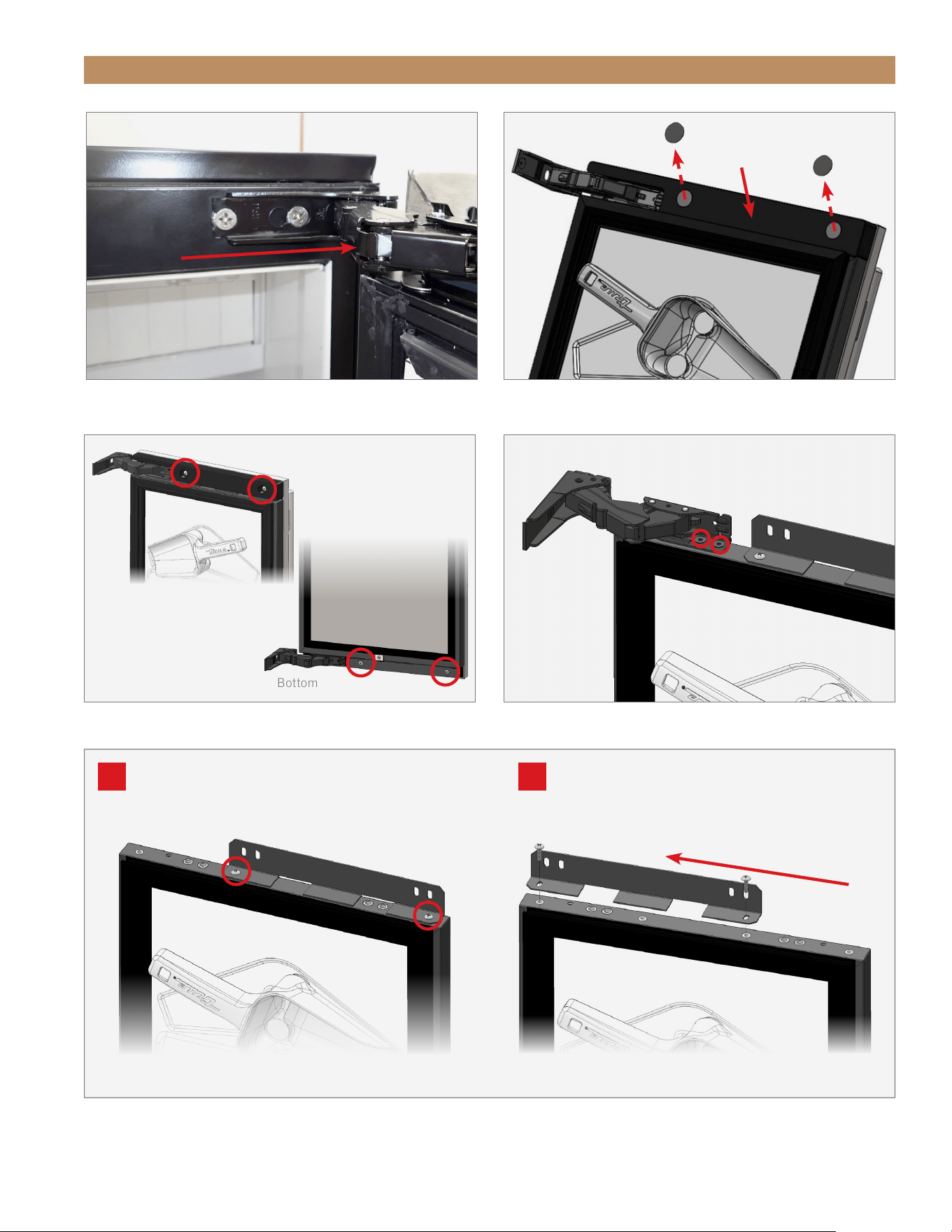
ADA HEIGHT 15" TRUE ICE
®
MACHINE INSTALL GUIDETEC_TM_157 REV. B EN
08/22/2022
Page 75 of 80
FIG. 1.
Slide the door off the hinge bolts through the keyhole slots.
SERVICING, REPLACING COMPONENTS & ADJUSTMENTS
FIG. 3.
Spacer and door bracket screw locations.
FIG. 4.
Hinge door screw locations. Top hinge shown.
FIG. 5.
Top Bracket shown.
A: Door Skin bracket screw locations.
B: Move the door skin bracket to the opposite side.
FIG. 2.
Remove the NSF cover screw caps.
NSF Cover
Screw cap
Screw cap
Top
Bottom
A B
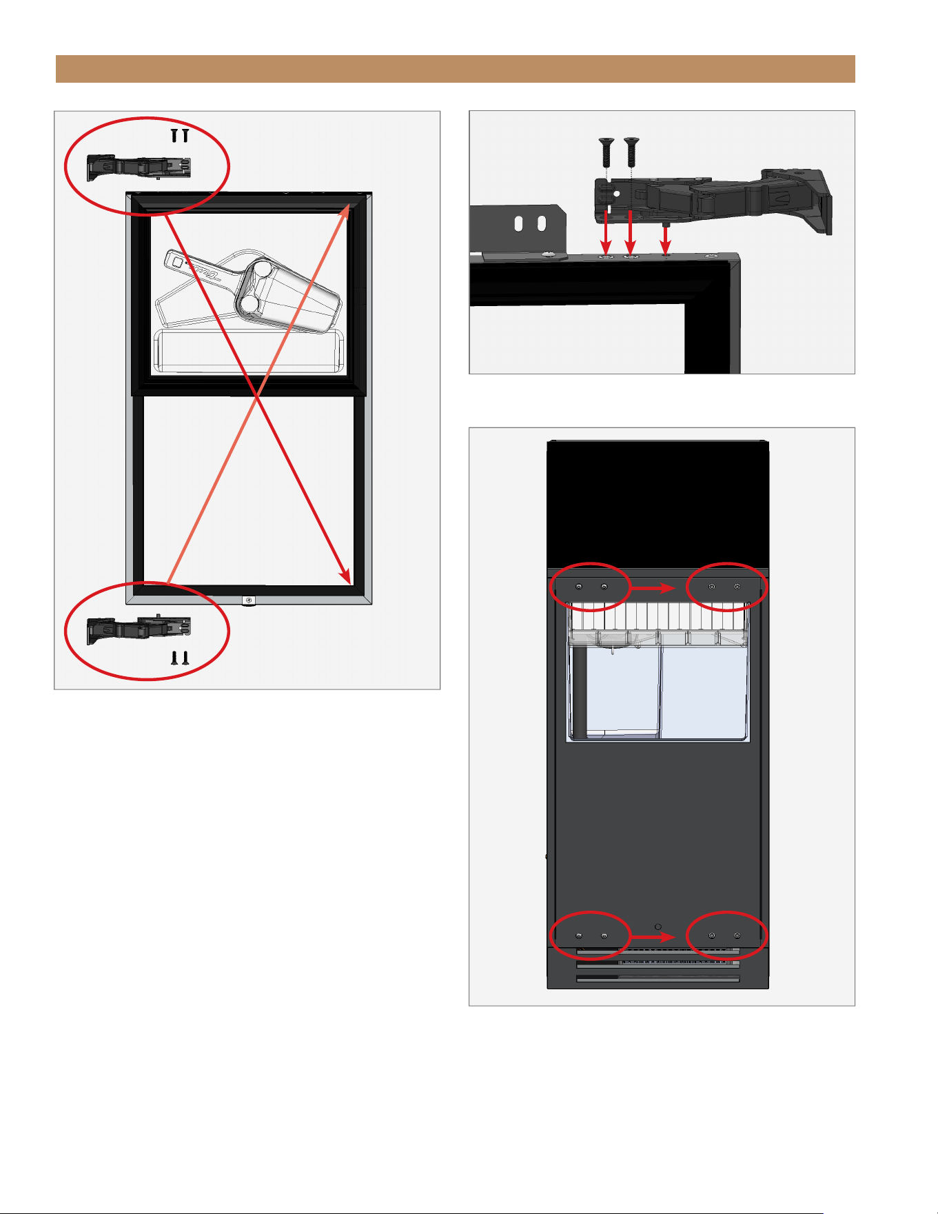
TRUE RESIDENTIAL
®
P#829074 TEC_TM_157 REV. B EN08/22/2022Page 76 of 80
SERVICING, REPLACING COMPONENTS & ADJUSTMENTS
FIG. 6.
Switch the top and bottom hinge assemblies with each other.
FIG. 8.
Move the remaining door hardware to the opposite side.
FIG. 7.
Install the hinge assembly.
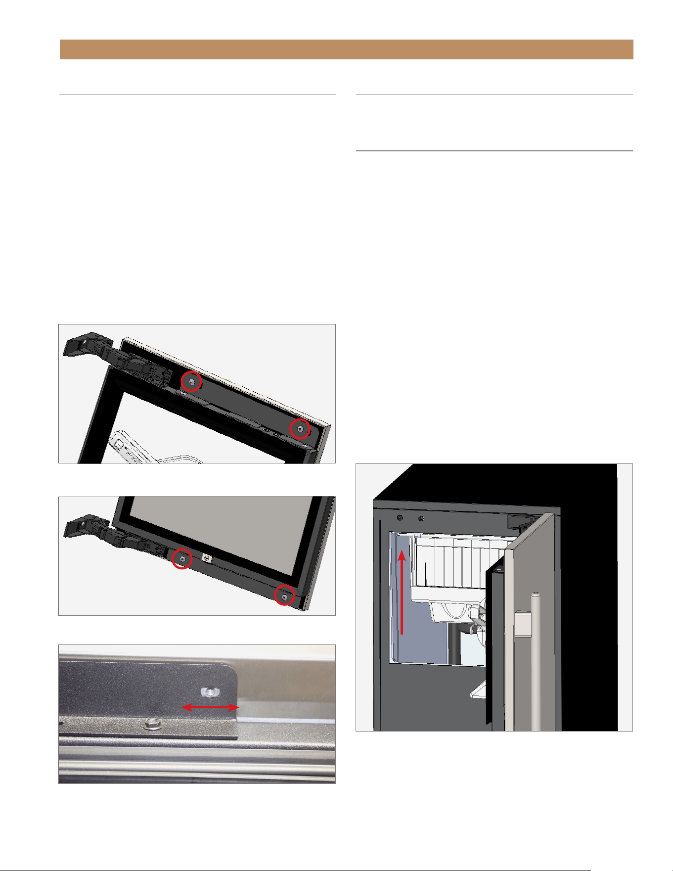
ADA HEIGHT 15" TRUE ICE
®
MACHINE INSTALL GUIDETEC_TM_157 REV. B EN
08/22/2022
Page 77 of 80
SERVICING, REPLACING COMPONENTS & ADJUSTMENTS
DOOR ADJUSTMENT
Door skin bracket screw holes are slotted to assist with
door adjustment. See figs. 1–3
PROCEDURE
1. If applicable, remove the NSF cover screw caps.
2. Loosen the door skin bracket and spacer screws.
See figs. 1–3
3. Adjust the door skin / panel as needed.
4. Tighten the door skin bracket and spacer screws.
5. If applicable, reinstall NSF cover screw caps.
FIG. 1.
Spacer / top door bracket screw locations.
FIG. 2.
Bottom door bracket screw locations.
FIG. 3.
Bracket screw holes are slotted for easy adjustment. Screw
removed for illustration.
HANDLE TIGHTENING
Tighten the handle with a 3/32" Allen wrench.
CONTACT US
For any questions about installation, please contact
your TRUE dealer or TRUE Residential Technical
Service. Please have your model and serial number
(see serial label location below) available so we can
better assist you with your service- or parts-related
inquires.
Customer Service
Phone: 888-616-8783
info@true-residential.com
Warranty Department
Phone: 844-849-6179
TrueResidentialWarranty@truemfg.com
Service Department
Phone: 844-746-9423
TrueResidentialService@truemfg.com

TRUE RESIDENTIAL
®
P#829074 TEC_TM_157 REV. B EN08/22/2022Page 78 of 80
NOTES

ADA HEIGHT 15" TRUE ICE
®
MACHINE INSTALL GUIDETEC_TM_157 REV. B EN
08/22/2022
Page 79 of 80
ADA TRUE RESIDENTIAL
®
WARRANTY STATEMENT
ADA TRUE RESIDENTIAL
®
WARRANTY STATEMENT
TWO-YEAR PARTS & LABOR WARRANTY
TRUE
®
warrants to the original purchaser of every new TRUE refrigerated unit, the cabinet and all parts thereof, to be free from defects in material or
workmanship under normal and proper use and maintenance as specified by TRUE and upon proper installation and start-up in accordance with the
instruction packet supplied with each TRUE unit. TRUE’s obligation under this warranty is limited to a period of two (2) years from the date of original
installation. Any warranty coverage is dependent on the purchase date of the cabinet being within 27 months of the original ship date from TRUE.
ADDITIONAL THREE-YEAR COMPRESSOR WARRANTY
In addition to the Two (2) year warranty stated above, TRUE warrants its hermetically and semi-hermetically sealed compressor to be free from defects in both
material and workmanship under normal and proper use and maintenance service for a period of three (3) additional years the date of original installation. Any
part covered under this warranty that is determined by TRUE to have been defective within this time frame, is limited to the repair or replacement, including
labor charges, of defective parts or assemblies. Compressors determined by TRUE to have been defective within this extended time period will, at TRUE’s
option, be either repaired or replaced with a compressor or compressor parts of similar design and capacity. The three (3) year extended compressor warranty
applies only to hermetically and semi-hermetically sealed parts of the compressor and does not apply to any other parts or components, including, but not
limited to: cabinet, paint finish, temperature control, refrigerant, metering device, driers, motor starting equipment, fan assembly or any other electrical
component, etcetera.
COMPRESSOR WARRANTY
The three (3) year compressor warranty detailed above will be voided if the following procedure is not carefully adhered to:
1. This system contains R600 refrigerant and polyol ester lubricant. The polyol ester lubricant has rapid moisture absorbing qualities. If long exposure to
the ambient conditions occur, the lubricant must be removed and replaced with new. For oil amounts and specifications please call TRUE technical service
department (855-372-1368). Failure to comply with recommended lubricant specification will void the compressor warranty.
2. Drier replacement is very important and must be changed when a system is opened for servicing. An OEM exact replacement should be used. The new drier
must also be the same capacity as the drier being replaced.
3. Micron level vacuums must be achieved to ensure low moisture levels in the system. 500 microns or lower must be obtained
DISPLAY PRODUCTS
True Residential Products on showroom display that are sold more than 2 years and 3 months (27 months) from the invoice date to the dealer would carry a
1 year parts and labor warranty, along with an additional 2 year compressor, parts only warranty.
TERMS APPLICABLE TO EACH WARRANTY
Any part covered under the above warranties that is determined by TRUE to have been defective within the time frame is limited to the repair or replacement,
including labor charges, of defective parts or assemblies. The labor warranty shall include standard straight time labor charges only and reasonable travel time,
as determined by TRUE.
WARRANTY CLAIMS
All claims for labor or parts must be made directly through TRUE. All claims should include: model number and serial number of cabinet, proof of purchase,
and date of installation. In case of warranted compressor, the compressor model tag must be returned to TRUE along with the above listed information. Any
action for breach of these warranty provisions must be commenced within three (3) months of the defect giving rise to the breach.
WHAT IS NOT COVERED BY THIS WARRANTY
TRUE’s sole obligation under this warranty is limited to either repair or replacement of parts, subject to the additional limitations below. This warranty neither
assumes nor authorizes any person to assume obligations other than those expressly covered by this warranty.
NO CONSEQUENTIAL DAMAGES
TRUE is not responsible for economic loss, profit loss; or special, indirect or consequential damages, including without limitation, losses or damages arising
from food or product spoilage claims whether or not on account or refrigeration failure.
WARRANTY IS NOT TRANSFERABLE
This warranty is not assignable and applies only in favor of the original purchaser/user to whom delivered. Any such assignment or transfer shall void the
warranties herein made and shall void all warranties, express or implied, including any warranty or merchantability or fitness for a particular purpose.
IMPROPER USAGE
TRUE assumes no liability for parts or labor coverage for component failure or other damages resulting from improper usage or installation or failure to clean
and/or maintain product as set forth in the warranty packet provided with the unit.
ALTERATION OR NEGLECT
TRUE is not responsible for the repair or replacement of any parts that TRUE determines have been subjected after the date of manufacture to alteration,
neglect, abuse, misuse, accident, damage during transit or installation, fire, flood, or act of God.
IMPROPER ELECTRICAL CONNECTIONS
TRUE is not responsible for the repair or replacement of failed or damaged components resulting from electrical power failure, high or low voltage, use of
extension cords, or improper grounding of the unit.
YOUR RIGHTS UNDER STATE LAW
This warranty gives you specific legal rights and you may have other rights that vary from state to state. Some states do not allow the exclusion or limitation of
consequential damages or a limitation on how long an implied warranty lasts, so the above exclusion or limitation may not apply to you.
ENVIRONMENTAL ATTRIBUTES
Any and all environmental attributes, including environmental offset credit rights, with respect to TRUE refrigeration units manufactured after September 1,
2015, shall remain the property of TRUE Manufacturing Co., Inc. and are not transferred.
OUTSIDE U.S./CANADA
This warranty does not apply to, and TRUE is not responsible for, any warranty claims made on products sold or used outside the United States or Canada.
SUBMIT WARRANTY CLAIMS TO: True Residential
2001 East Terra Lane
O’Fallon MO 63366
181839_DF_12.21 API#2480

TRUE RESIDENTIAL
®
P#829074 TEC_TM_157 REV. B EN08/22/2022Page 80 of 80
AL_BP_181044_08.22
PRESERVE THE MOMENT
®
CONTACT US
true-residential.com
636.240.2400
|
toll free 888.616.8783