
Visit our website at: http://www.harborfreight.com
email our technical support at: [email protected]
59726
2HP, 5 MICRON, 35 GAL
DUST COLLECTOR
Owner’s Manual & Safety Instructions
Save This Manual Keep this manual for the safety warnings and precautions, assembly,
operating, inspection, maintenance and cleaning procedures. Write the product’s serial number in the
back of the manual (or month and year of purchase if product has no number). Keep this manual and the
receipt in a safe and dry place for future reference. 24d
When unpacking, make sure that the product is intact
and undamaged. If any parts are missing or broken,
please call 1‑888‑866‑5797 as soon as possible.
Copyright
©
2022 by Harbor Freight Tools
®
. All rights reserved.
No portion of this manual or any artwork contained herein may be reproduced in
any shape or form without the express written consent of Harbor Freight Tools.
Diagrams within this manual may not be drawn proportionally. Due to continuing
improvements, actual product may differ slightly from the product described herein.
Tools required for assembly and service may not be included.
Read this material before using this product.
Failure to do so can result in serious injury.
SAVE THIS MANUAL.
Page 2 For technical questions, please call 1-888-866-5797. Item 59726
SaFety OperatiOn MaintenanceSetup
table of contents
Safety ......................................................... 2
Specifications ............................................. 6
Setup .......................................................... 7
Operation ................................................... 11
Maintenance .............................................. 12
Parts List and Diagram .............................. 14
Warranty .................................................... 16
WarninG SyMBOLS anD DeFinitiOnS
This is the safety alert symbol. It is used to alert you to potential
personal injury hazards. Obey all safety messages that
follow this symbol to avoid possible injury or death.
Indicates a hazardous situation which, if not avoided,
will result in death or serious injury.
Indicates a hazardous situation which, if not avoided,
could result in death or serious injury.
Indicates a hazardous situation which, if not avoided,
could result in minor or moderate injury.
Addresses practices not related to personal injury.
instructions pertaining to a risk of Fire, electric Shock, or injury to persons
iMpOrtant SaFety inStructiOnS
When using an electrical appliance, basic precautions should always be followed, including the following:
reaD aLL inStructiOnS BeFOre uSinG tHiS appLiance.
to reduce the risk of fire, electric shock, or injury:
1. Do not leave appliance when plugged in. Unplug
from outlet when not in use and before servicing.
2. Do not use outdoors or on wet surfaces.
3. Do not allow to be used as a toy. Close attention
is necessary when used by or near children.
4. Use only as described in this manual. Use only
manufacturer’s recommended attachments.
5. Do not use with damaged cord or plug.
If appliance is not working as it should, has been
dropped, damaged, left outdoors, or dropped
into water, return it to a service center.
6. Do not pull or carry by cord, use cord as a handle,
close a door on cord, or pull cord around sharp
edges or corners. Do not run appliance over cord.
Keep cord away from heated surfaces.
7. Do not unplug by pulling on cord.
To unplug, grasp the plug, not the cord.
8. Do not handle plug or appliance with wet hands.
9. Do not put any object into openings. Do not use
with any opening blocked; keep free of dust, lint,
hair, and anything that may reduce air flow.
10. Keep hair, loose clothing, fingers, and all parts of
body away from openings and moving parts.

Page 3For technical questions, please call 1-888-866-5797.Item 59726
SaFetyOperatiOnMaintenance Setup
11. Turn off all controls before unplugging.
12. Use extra care when cleaning on stairs.
13. Do not use to pick up flammable or
combustible liquids, such as gasoline, or
use in areas where they may be present.
14. Connect to a properly grounded outlet only.
See Grounding Instructions.
15. Do not pick up anything that is burning
or smoking, such as cigarettes,
matches, or hot ashes.
16. Do not use without dust bag
and/or filters in place.
17. FOR HOUSEHOLD USE ONLY.
18. Stay alert, watch what you are doing and use
common sense when operating an appliance.
Do not use an appliance while you are tired or under
the influence of drugs, alcohol or medication.
A moment of inattention while operating
appliances may result in serious personal injury.
19. Maintain labels and nameplates
on the appliance. These carry important safety
information. If unreadable or missing, contact
Harbor Freight Tools for a replacement.
20. People with pacemakers should consult their
physician(s) before use. Electromagnetic fields in
close proximity to heart pacemaker could cause
pacemaker interference or pacemaker failure.
21. The warnings, precautions, and instructions
discussed in this instruction manual cannot cover all
possible conditions and situations that may occur.
It must be understood by the operator that
common sense and caution are factors
which cannot be built into this product,
but must be supplied by the operator.
SaVe tHeSe inStructiOnS
Page 4 For technical questions, please call 1-888-866-5797. Item 59726
SaFety OperatiOn MaintenanceSetup
Grounding instructions
this appliance must be grounded. if it should malfunction or breakdown, grounding provides a path of
least resistance for electric current to reduce the risk of electric shock. this appliance is equipped with a
cord having an equipment-grounding conductor and grounding plug. the plug must be inserted into an
appropriate outlet that is properly installed and grounded in accordance with all local codes and ordinances.
improper connection of the equipment-grounding conductor can result in a risk of
electric shock. check with a qualified electrician or service person if you are in doubt as to
whether the outlet is properly grounded. Do not modify the plug provided with the appliance –
if it will not fit the outlet, have a proper outlet installed by a qualified electrician.
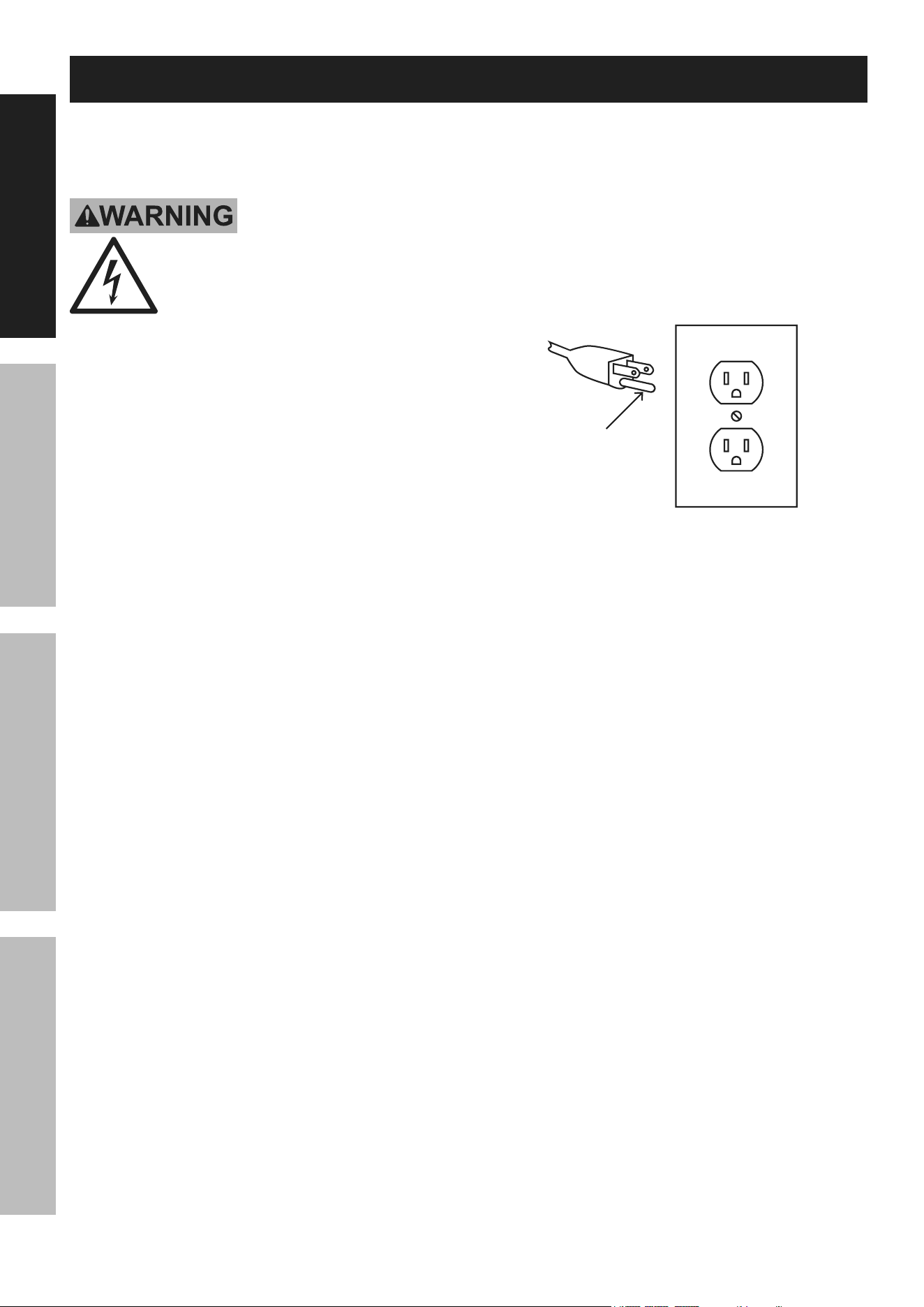
This appliance is for use on a nominal 120‑V circuit
and has a grounding attachment plug that looks like the
plug illustrated in 125 Vac 3-prong plug and Outlet.
Make sure that the appliance is connected to an
outlet having the same configuration as the plug.
No adaptor should be used with this appliance.
Grounding
pin
125 Vac 3-prong plug and Outlet
(for up to 125 Vac and up to 15 a)

Page 5For technical questions, please call 1-888-866-5797.Item 59726
SaFetyOperatiOnMaintenance Setup
extension cords
1. Grounded tools require a three wire extension
cord. Double Insulated tools can use either
a two or three wire extension cord.
2. As the distance from the supply outlet increases,
you must use a heavier gauge extension cord.
Using extension cords with inadequately sized wire
causes a serious drop in voltage, resulting in loss of
power and possible tool damage.
(See table a.) The smaller the gauge number
of the wire, the greater the capacity of the cord.
For example, a 14 gauge cord can carry a higher
current than a 16 gauge cord. (See table a.)
3. When using more than one extension cord
to make up the total length, make sure
each cord contains at least the minimum
wire size required. (See table a.)
4. If you are using one extension cord for more
than one tool, add the nameplate amperes
and use the sum to determine the required
minimum cord size. (See table a.)
5. If you are using an extension cord outdoors, make
sure it is marked with the suffix “W‑A” (“W” in
Canada) to indicate it is acceptable for outdoor use.
6. Make sure the extension cord is properly wired
and in good electrical condition. Always replace
a damaged extension cord or have it repaired
by a qualified electrician before using it.
7. Protect the extension cords from sharp objects,
excessive heat, and damp or wet areas.
recOMMenDeD MiniMuM Wire
GauGe FOr eXtenSiOn cOrDS*
(120/240 VOLt)
naMepLate
aMpereS
(at full load)
eXtenSiOn cOrD
LenGtH
25’
50’
75’
100’
150’
0 – 2.0 18 18 18 18 16
2.1 – 3.4 18 18 18 16 14
3.5 – 5.0 18 18 16 14 12
5.1 – 7.0 18 16 14 12 12
7.1 – 12.0 18 14 12 10 ‑
12.1 – 16.0 14 12 10 ‑ ‑
16.1 – 20.0 12 10 ‑ ‑ ‑
taBLe a
* Based on limiting the line
voltage drop to five volts at
150% of the rated amperes.

Page 6 For technical questions, please call 1-888-866-5797. Item 59726
SaFety OperatiOn MaintenanceSetup
Specifications
Electrical Rating
120VAC / 60Hz / 15A / 2HP
Single Phase
RPM 3450
Bag Dimensions
Top:19-1/2″ Dia. x 30″ L
Bottom: 19-1/2″ Dia. x 30-7/8″ L
Bag Filtration Ratio 5 Microns
Intake 4-3/8″ ID (screen & filter)
Exhaust Diameter 4-1/2″ ID With Screen
Page 7For technical questions, please call 1-888-866-5797.Item 59726
SaFetyOperatiOnMaintenance Setup
Setup - Before use:
read the entire iMpOrtant SaFety inFOrMatiOn section at the beginning of this
manual including all text under subheadings therein before set up or use of this product.
tO preVent SeriOuS inJury FrOM acciDentaL OperatiOn:
turn the power Switch of the appliance off and unplug the appliance from its
electrical outlet before performing any procedure in this section.
note: For additional information regarding the parts listed in the following pages,
refer to the Assembly Diagram near the end of this manual.
assembly
note: Your Dust Collector will require complete
assembly prior to use. It is important that you
read the entire manual to become familiar with the
product BEFORE you use the Dust Collector. Before
assembling the Dust Collector be sure that you have all
parts described in the Parts List and Assembly Diagram.
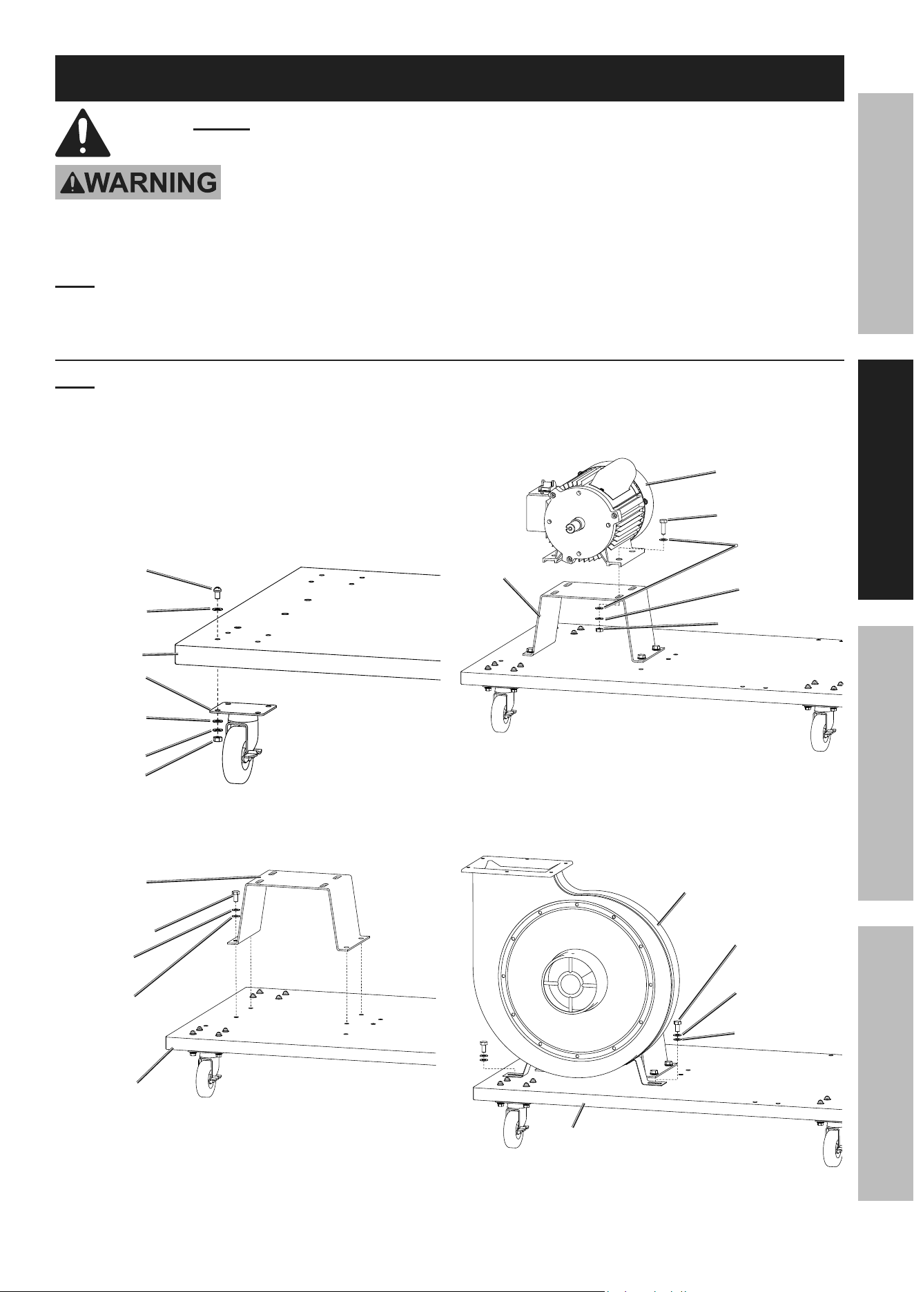
1. Assemble Casters (40) to Base Plate (41)
with Screws (42), Flat Washers (39),
Lock Washers (9), and Nuts (38).
Screw (42)
Flat
Washer (39)
Base
plate (41)
caster (40)
Flat
Washer (39)
nut (38)
Lock
Washer (9)
2. Assemble Motor Base (44) to Base Plate (41)
with Bolts (17), Lock Washers (16),
and Flat Washers (15).
Bolt (17)
Motor
Base (44)
Base
plate (41)
Flat
Washer (15)
Lock
Washer (16)
3. Assemble Motor (27) (Fan Housing (18) not
shown for visibility) to Motor Base (44) with
Bolts (28), Flat Washers (43), Lock Washers (16),
and Nuts (36). Leave hardware loose.
Motor (27)
nut (36)
Motor
Base (44)
Bolt (28)
Flat
Washer (43)
Lock
Washer (16)
4. Assemble Fan Housing (18) to Base Plate (41)
with Bolts (17), Flat Washers (15), and
Lock Washers (16) Tighten hardware,
then tighten loose hardware in Step 3.
Base
plate (41)
Fan
Housing (18)
Lock
Washer (16)
Flat
Washer (15)
Bolt (17)
Page 8 For technical questions, please call 1-888-866-5797. Item 59726
SaFety OperatiOn MaintenanceSetup
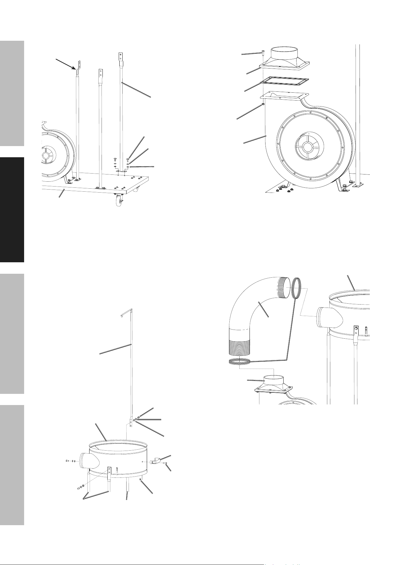
5. Assemble Collector Supports (29) with bend
facing inwards to Base Plate (41) with Bolts (17),
Lock Washers (16), and Flat Washers (15).
collector
Support (29)
Base
plate (41)
Bolt (17)
Lock
Washer (16)
Flat
Washer (15)
Bend
6. Assemble Collector to Collector Supports:
a. Assemble Collector (30) to first and
second Supports (29) with Bolts (17),
Lock Washers (16), and Flat Washers (15).
b. Assemble Filter Support (33) to third Support (29)
to Collector (30) with Bolts (17),
Lock Washers (16), and Flat Washers (15).
c. Assemble Handle (34) to Collector (30)
with Hex Screws (35) and Nuts (36).
1st & 2nd collector
Supports (29)
collector (30)
Handle (34)
nut (36)
Filter
Support (33)
Bolt (17)
Lock
Washer (16)
Flat
Washer (15)
Hex
Screw (35)
3rd collector
Support (29)
7. Assemble Outlet (21) and Outlet Gasket (20) to
Fan Housing (18) with Bolts (22) and Lock Nuts (19).
Fan
Housing (18)
Outlet
Gasket (20)
Outlet (21)
Bolt (22)
Lock
nut (19)
8. Slide Hose Clamps (23) onto Hose (24).
Loosen screws on Hose Clamps as needed.
9. Slide Hose (24) with Hose Clamps (23) onto
Outlet (21) and Collector (30). With Hose in place
and Hose Clamps in‑line with Outlet and Collector
openings, tighten screws on Hose Clamps until
Hose is securely fastened to Outlet and Collector.
Hose (24)
Hose
clamp (23)
collector (30)
Outlet (21)
Page 9For technical questions, please call 1-888-866-5797.Item 59726
SaFetyOperatiOnMaintenance Setup
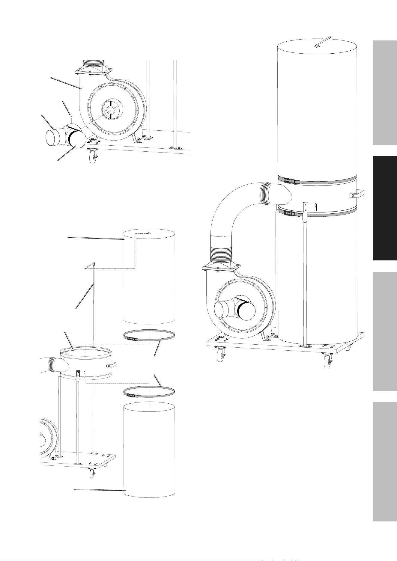
10. Remove Screw (3) from Fan Housing (18).
Assemble Y‑Inlet (2) to Fan Housing and secure
with Screw. If only using one inlet on Y‑Inlet (2),
cap off the unused inlet with the Inlet Cap (1).
Fan
Housing (18)
y-inlet (2)
Screw (3)
inlet
cap (1)
11. Hang Filter Bag (32) from Filter Support (33).
Slide Filter Clamp (31) over Filter Bag and
secure Filter Bag to Collector (30).
12. Slide Filter Clamp (31) over Collection Bag (37)
and secure Collection Bag to Collector (30).
Filter
Support (33)
collector (30)
Filter
Bag (32)
collection
Bag (37)
Filter
clamp (31)
13. Finished Assembly.
Page 10 For technical questions, please call 1-888-866-5797. Item 59726
SaFety OperatiOn MaintenanceSetup
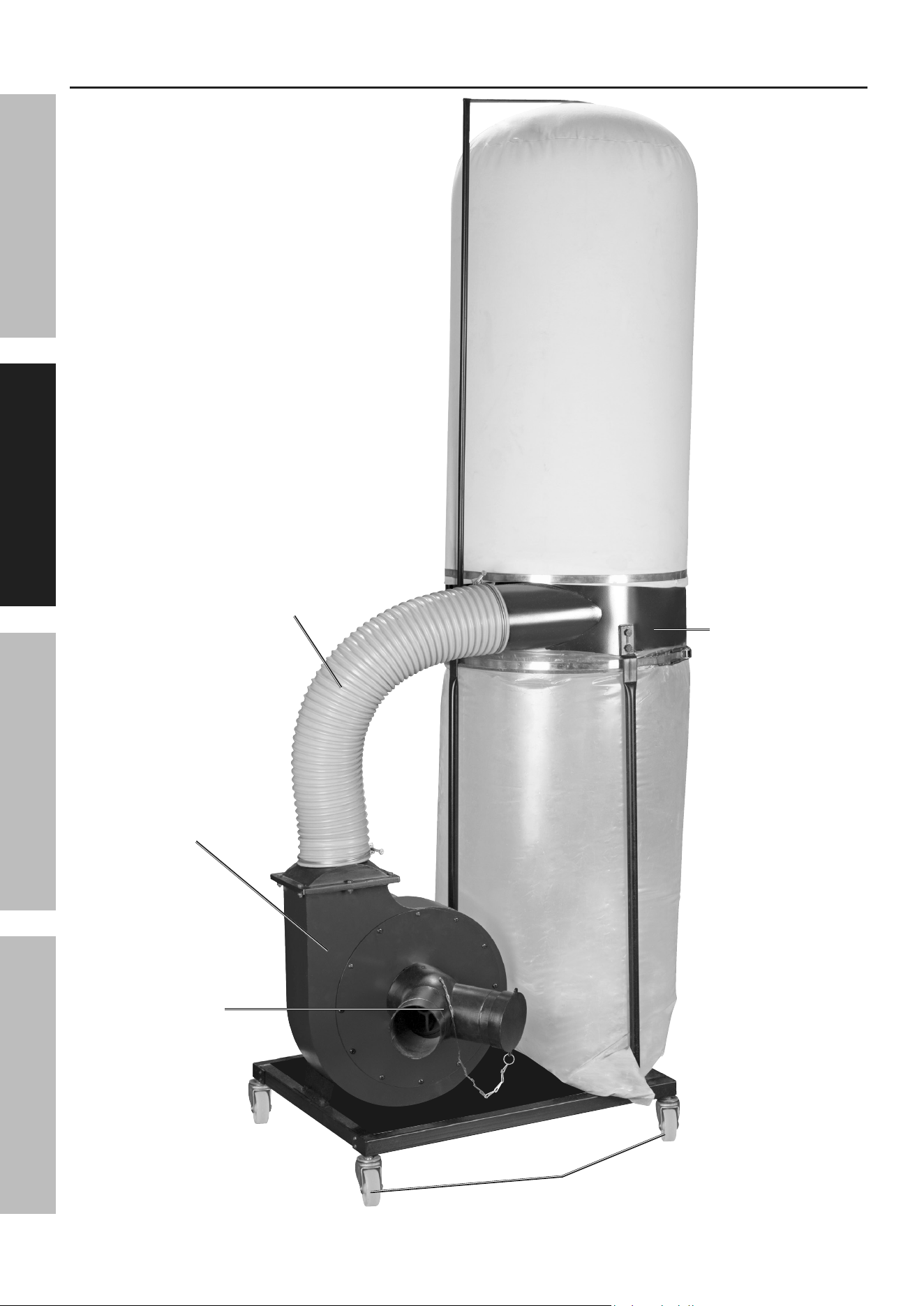
Functions
Hose
Filter Bag
collection
Bag
collector
caster
y-inlet
Fan Housing

Page 11For technical questions, please call 1-888-866-5797.Item 59726
SaFetyOperatiOnMaintenance Setup
Operating instructions
read the entire iMpOrtant SaFety inFOrMatiOn section at the beginning of this
manual including all text under subheadings therein before set up or use of this product.
tool Set up
tO preVent SeriOuS inJury FrOM acciDentaL OperatiOn:
Make sure that the trigger is in the off-position and unplug the tool from its
electrical outlet before performing any procedure in this section.
Workpiece and Work area Set up
1. Designate a work area that is clean and well lit.
The work area must not allow access by children
or pets to prevent distraction and injury.
2. Route the power cord along a safe route to reach
the work area without creating a tripping hazard or
exposing the power cord to possible damage. The
power cord must reach the work area with enough
extra length to allow free movement while working.
3. Secure loose workpieces using a vise or clamps
(not included) to prevent movement while working.
4. There must not be objects, such as utility lines,
nearby that will present a hazard while working.
General Operating instructions
tO preVent SeriOuS inJury FrOM acciDentaL OperatiOn:
turn the Switch off and unplug the power cord from its electrical outlet before removing the power Head.
Do not tamper with or remove the grounding pole on the plug. you must use
this unit with a 3 pole receptacle. if you use an extension cord, it must meet
amperage specified (16 aWG), and the cord must be 3-pronged.
This unit is designed for use with an existing dust
system, or you can construct a new system.
1. If constructing a new system, connect 4″ vent pipe
(not included) to the 4″ inlet side of the collector.
2. Determine the size of the dust ports on your
tools and run vacuum hoses from each
tool to an appropriate sized adapter, and
into the 4″ vent pipe (none included).
3. Make sure that the Switch is in its off position.
Plug the Power Cord into the power outlet.
4. Turn the switch on to operate the Dust Collector.
5. Make sure the Collection Bag (37)
is on tight and not leaking.
6. During operation, periodically check how full
the Collection Bag is. Do not let it fill more
than 3/4 full. A completely full bag puts a
lot of stress on the bag and the clamp.
7. To change Collection Bag, wear ANSI‑approved
safety goggles, and a dust mask. Turn Dust
Collector off, remove the Filter Clamp (31), and
empty the bag. Reinstall the bag and clamp.
8. To prevent accidents, turn off the appliance and
unplug it after use.
Empty and clean Bags, clean Filter
(see cleaning Filter on page 12),
then store the appliance indoors
out of children’s reach.
Page 12 For technical questions, please call 1-888-866-5797. Item 59726
SaFety OperatiOn MaintenanceSetup
user-maintenance and Storage
procedures not specifically explained in this manual must
be performed only by a qualified technician.
tO preVent SeriOuS inJury FrOM acciDentaL OperatiOn:
turn the power Switch of the appliance off and unplug the appliance from its
electrical outlet before performing any procedure in this section.
tO preVent SeriOuS inJury FrOM appLiance FaiLure:
Do not use damaged equipment. if abnormal noise or vibration
occurs, have the problem corrected before further use.
cleaning, Maintenance, and Lubrication
1. BeFOre eacH uSe, inspect the
general condition of the appliance. Check for:
• loose hardware,
• misalignment or binding of moving parts,
• cracked or broken parts,
• damaged electrical wiring, and
• any other condition that may
affect its safe operation.
2. aFter uSe, wipe external surfaces of
the appliance with clean cloth. Store in an
indoor dry area out of reach of children.
3. All parts are permanently lubricated.
Do not use additional lubrication.
4. Check Collection and Filter Bags (1 each) prior to
each use for tears or fraying. Replace if necessary.
5. Periodically tighten the Filter Clamps (31)
and Hose Clamps (23).
6. Keep the Motor (27) clean of dirt and debris.
7. WarninG! tO preVent SeriOuS
inJury: if the supply cord of this appliance
is damaged, it must be replaced only
by a qualified service technician.
cleaning Filter
to ensure proper operation, clean the Filter regularly. torn Filters should be replaced:
cLOtH FiLter:
1. Gently tap or brush dirt off outdoors.
2. Wash Cloth Filter using mild soap and water.
3. Rinse all soap and dust out thoroughly.
4. allow the cloth Filter to dry for at
least one day before reinstalling.
WarninG! tO preVent SeriOuS inJury:
installing a wet Filter will increase the risk
of electric shock and may damage the
vacuum.
5. Reinstall the Filter.
Page 13For technical questions, please call 1-888-866-5797.Item 59726
SaFetyOperatiOnMaintenance Setup
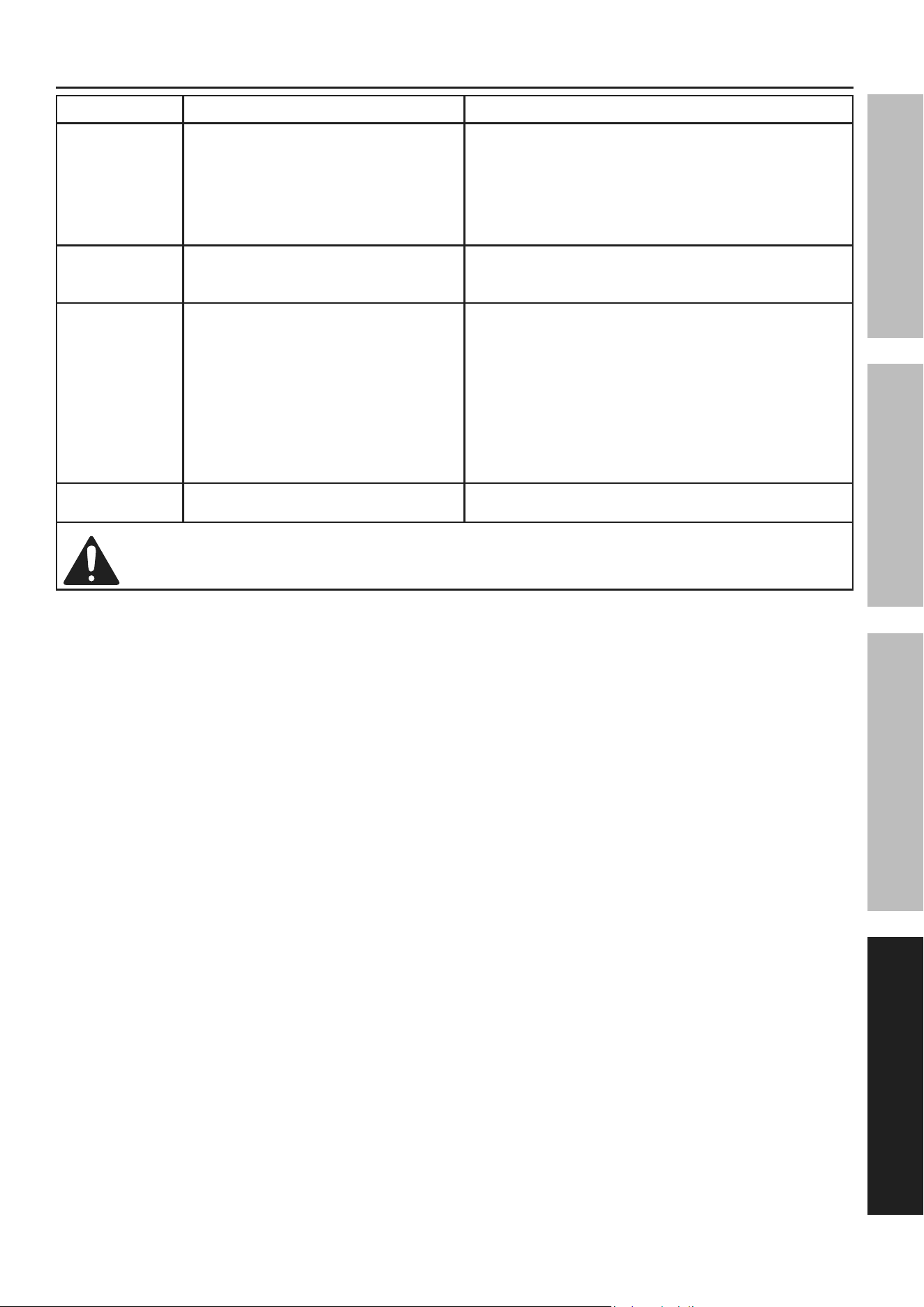
troubleshooting
problem possible causes Likely Solutions
Tool will not start. 1. Cord not connected.
2. No power at outlet.
3. Internal damage or wear.
1. Check that cord is plugged in.
2. Check power at outlet. If outlet is unpowered,
turn off tool and check circuit breaker.
If breaker is tripped, make sure circuit is right
capacity for tool and circuit has no other loads.
3. Have technician service tool.
Tool operates
slowly.
Extension cord too long or
wire size too small.
Eliminate use of extension cord. If an extension cord
is needed, use one with the proper diameter for its
length and load. See taBLe a on page 5.
Overheating. 1. Blocked motor housing vents.
2. Motor being strained by long or
small diameter extension cord.
3. Motor being strained by
over‑full Collection Bag.
1. Wear ANSI‑approved safety goggles and
NIOSH‑approved dust mask/respirator while
blowing dust out of motor using compressed air.
2. Eliminate use of extension cord.
If an extension cord is needed, use one with
the proper diameter for its length and load.
See taBLe a on page 5.
3. Empty Collection Bag. Do not
allow to fill past 3/4 full.
Suction loss. Collection Bag / Filter Bag
is loose or leaking.
Tighten Clamps on Bags.
Follow all safety precautions whenever diagnosing or servicing the tool.
Disconnect power supply before service.
Page 14 For technical questions, please call 1-888-866-5797. Item 59726
SaFety OperatiOn MaintenanceSetup
parts List and Diagram
pLeaSe reaD tHe FOLLOWinG careFuLLy
THE MANUFACTURER AND/OR DISTRIBUTOR HAS PROVIDED THE PARTS LIST AND ASSEMBLY DIAGRAM
IN THIS MANUAL AS A REFERENCE TOOL ONLY. NEITHER THE MANUFACTURER OR DISTRIBUTOR
MAKES ANY REPRESENTATION OR WARRANTY OF ANY KIND TO THE BUYER THAT HE OR SHE IS
QUALIFIED TO MAKE ANY REPAIRS TO THE PRODUCT, OR THAT HE OR SHE IS QUALIFIED TO REPLACE
ANY PARTS OF THE PRODUCT. IN FACT, THE MANUFACTURER AND/OR DISTRIBUTOR EXPRESSLY
STATES THAT ALL REPAIRS AND PARTS REPLACEMENTS SHOULD BE UNDERTAKEN BY CERTIFIED AND
LICENSED TECHNICIANS, AND NOT BY THE BUYER. THE BUYER ASSUMES ALL RISK AND LIABILITY
ARISING OUT OF HIS OR HER REPAIRS TO THE ORIGINAL PRODUCT OR REPLACEMENT PARTS
THERETO, OR ARISING OUT OF HIS OR HER INSTALLATION OF REPLACEMENT PARTS THERETO.
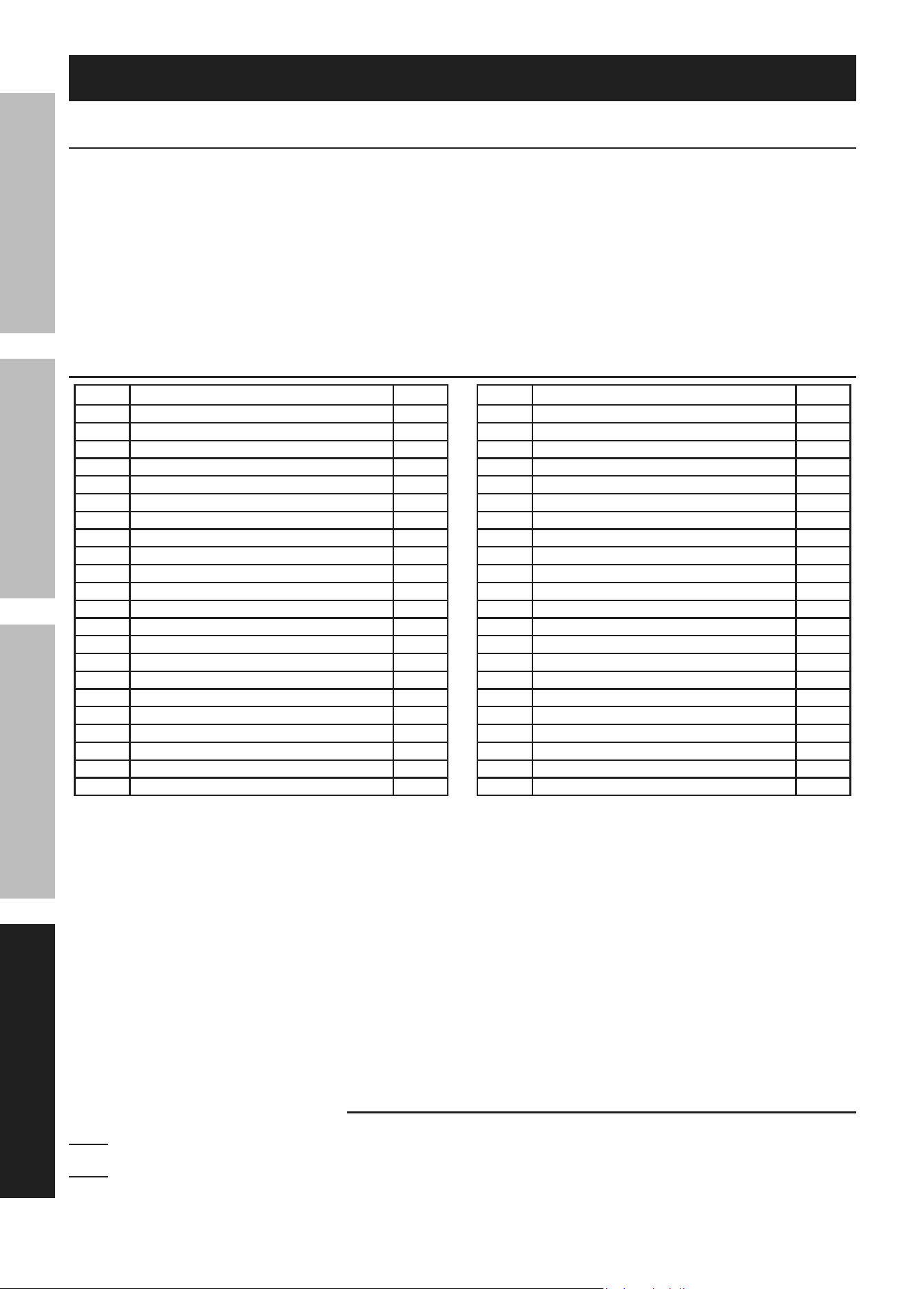
parts List
part Description Qty
1 Inlet Cap 1
2 Y‑Inlet 1
3 Screw M5x10 1
4 Chain 1
5 Screw M6x10 12
6 Inlet Cover 1
7 Inlet Cover Gasket 1
8 Screw M6x20 1
9 Lock Washer 6 17
10 Special Washer 1
11 Impeller 1
12 Bolt M10x16 4
13 Lock Washer 10 4
14 Flat Washer 10 4
15 Flat Washer 8 18
16 Lock Washer 8 22
17 Bolt M8X16 18
18 Fan Housing 1
19 Lock Nut M6 6
20 Outlet Gasket 1
21 Outlet 1
22 Bolt M6x20 6
part Description Qty
23 Hose Clamp Ø120‑Ø140 2
24 Hose Ø125x75 1
25 Rubber Gasket 1
26 Flat Key 5x30 1
27 Motor 1
28 Bolt M8x25 4
29 Collector Support 3
30 Collector 1
31 Filter Clamp 2
32 Filter Bag 1
33 Filter Support 1
34 Handle 1
35 Hex Socket Screw 2
36 Nut M8 6
37 Collection Bag 1
38 Nut M6 16
39 Flat Washer 6 32
40 Caster 4
41 Base Plate 1
42 Screw M6x12 16
43 Flat Washer 8 8
44 Motor Base 1
record product’s Serial number Here:
note: if product has no serial number, record month and year of purchase instead.
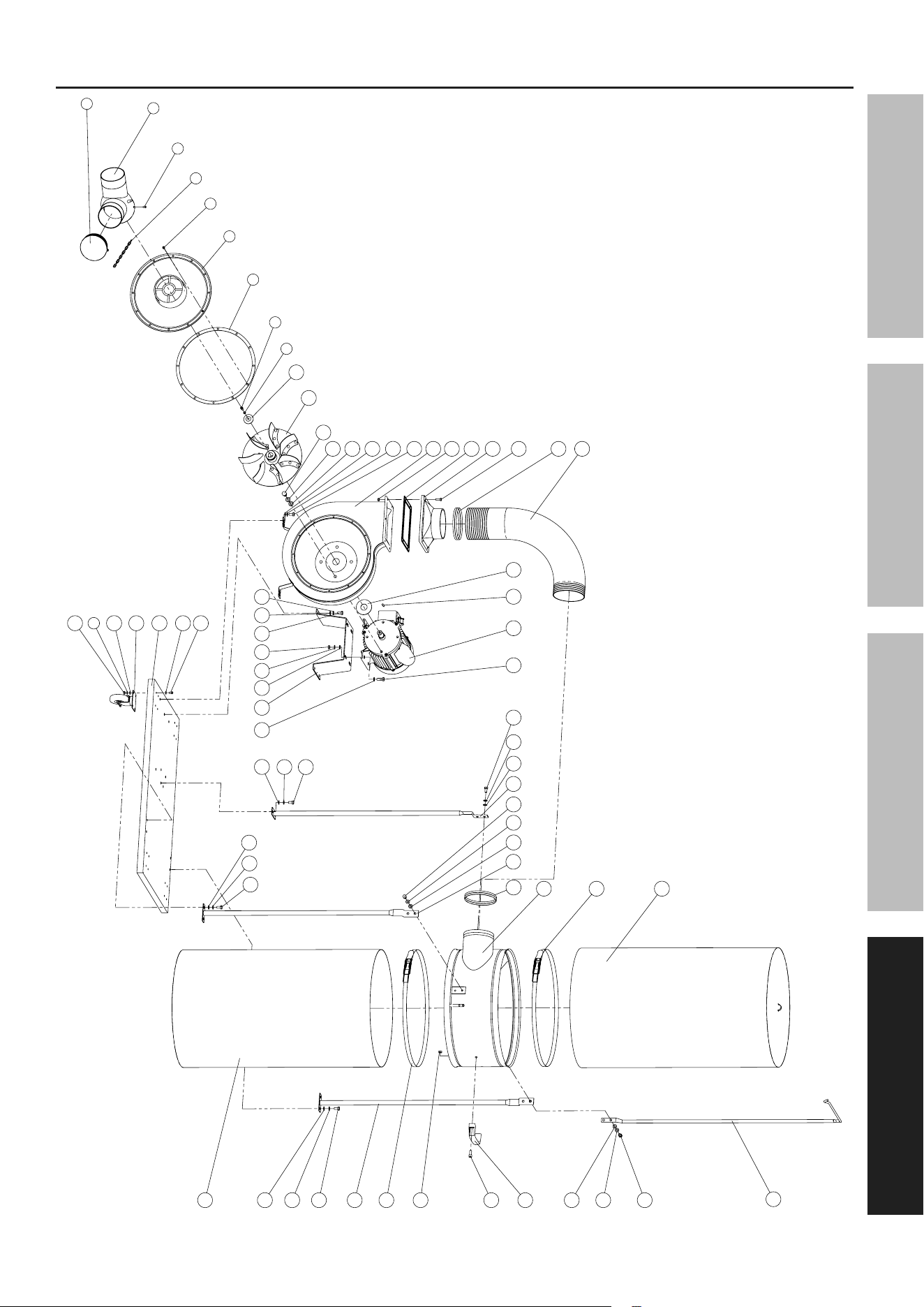
note: Some parts are listed and shown for illustration purposes only, and are not
available individually as replacement parts. Reference UPC 193175481627.
Page 15For technical questions, please call 1-888-866-5797.Item 59726
SaFetyOperatiOnMaintenance Setup
assembly Diagram
2
1
3
4
5
6
7
8
9
10
11
12
13
18
19
20
21
22
23
24
15
17
26
2725 28
43
44
16
36
15
17
42
39
41
40
9
38
17
29
17
15
32
31
30
23
31
37
29
15
17
17
15
33
17
15
34
35
17
16
36
29
16
16
15
16
16
15
16
39
16
16
43
14

Limited 90 Day Warranty
Harbor Freight Tools Co. makes every effort to assure that its products meet high quality and durability standards,
and warrants to the original purchaser that this product is free from defects in materials and workmanship for the
period of 90 days from the date of purchase. This warranty does not apply to damage due directly or indirectly,
to misuse, abuse, negligence or accidents, repairs or alterations outside our facilities, criminal activity, improper
installation, normal wear and tear, or to lack of maintenance. We shall in no event be liable for death, injuries
to persons or property, or for incidental, contingent, special or consequential damages arising from the use of
our product. Some states do not allow the exclusion or limitation of incidental or consequential damages, so the
above limitation of exclusion may not apply to you. THIS WARRANTY IS EXPRESSLY IN LIEU OF ALL OTHER
WARRANTIES, EXPRESS OR IMPLIED, INCLUDING THE WARRANTIES OF MERCHANTABILITY AND FITNESS.
To take advantage of this warranty, the product or part must be returned to us with transportation charges
prepaid. Proof of purchase date and an explanation of the complaint must accompany the merchandise.
If our inspection verifies the defect, we will either repair or replace the product at our election or we may
elect to refund the purchase price if we cannot readily and quickly provide you with a replacement. We will
return repaired products at our expense, but if we determine there is no defect, or that the defect resulted
from causes not within the scope of our warranty, then you must bear the cost of returning the product.
This warranty gives you specific legal rights and you may also have other rights which vary from state to state.
26677 agoura road • calabasas, ca 91302 • 1-888-866-5797