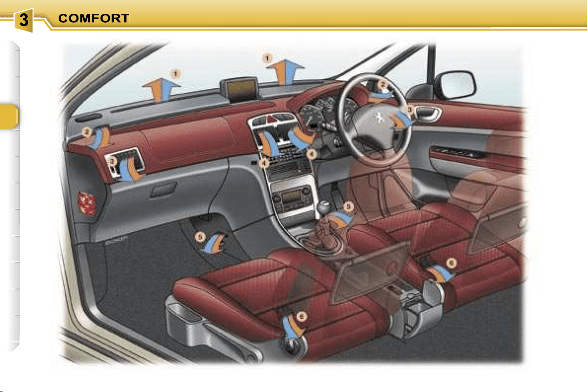
1.
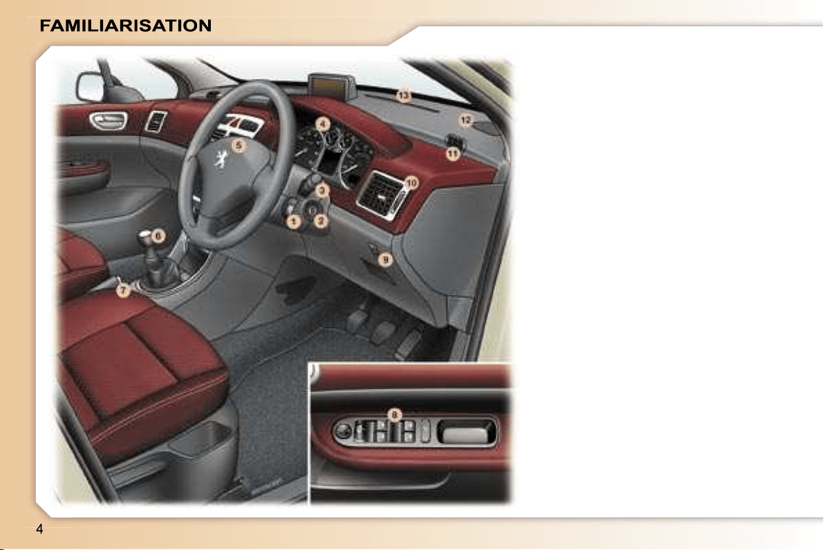
Audio remote control stalk.
2.
Steering lock and ignition.
3.
Windscreen wipers/wash-wipe/
trip computer stalk.
4.
Instrument dials.
5.
Driver’s air bag.
Horn.
6.
Gear lever.
7.
Handbrake.
8.
Electric mirror controls.
Window controls.
Rear window disarming control.
9.
Headlamp height adjustment.
10.
Side adjustable and closing
vent.
11.
Side window demisting vent.
12.
Speaker (tweeter) location.
13.
Windscreen demisting vents.
INSTRUMENTS AND CONTROLS
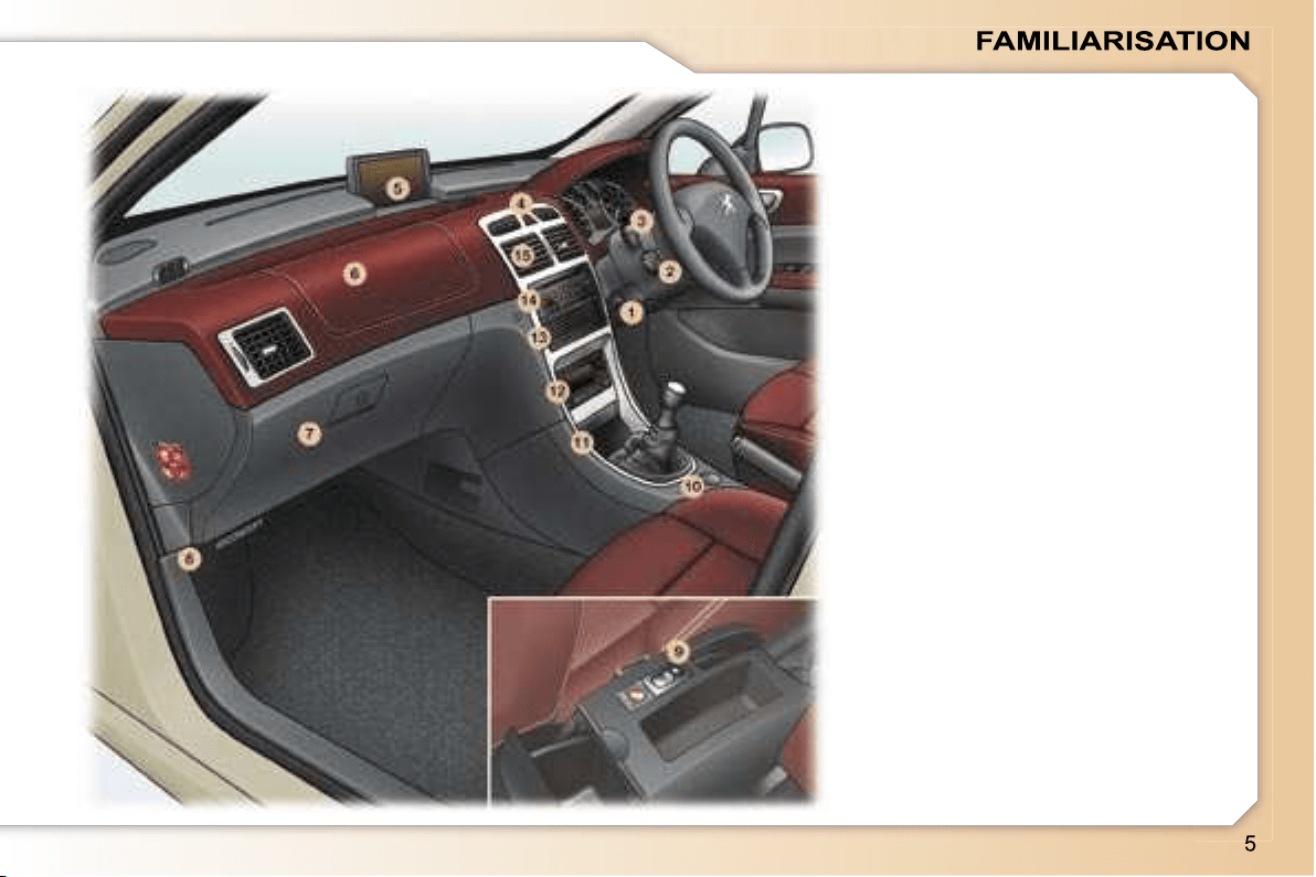
1.
Steering wheel adjustment
control.
2.
Cruise control/speed limiter
switch.
3.
Lights and direction indicators
stalk.
4.
Alarm button.
Central locking button.
Hazard warning lights switch.
Electronic stability control
(ESP/ASR) button.
Front seat belts unfastening/not
fastened warning light.
5.
Multifunction display.
6.
Passenger air bag.
7.
Glove box/Audio/video sockets/
Fuse box.
8.
Bonnet opening control.
9.
Panoramic roof shutter switch.
10.
12 volt socket.
11.
Front ashtray.
12.
Ventilation/air conditioning
controls.
13.
CD changer.
14.
RD4 audio equipment or RT3
GPS audio/telephone.
15.
Central adjustable and closing
vents.
INSTRUMENTS AND CONTROLS
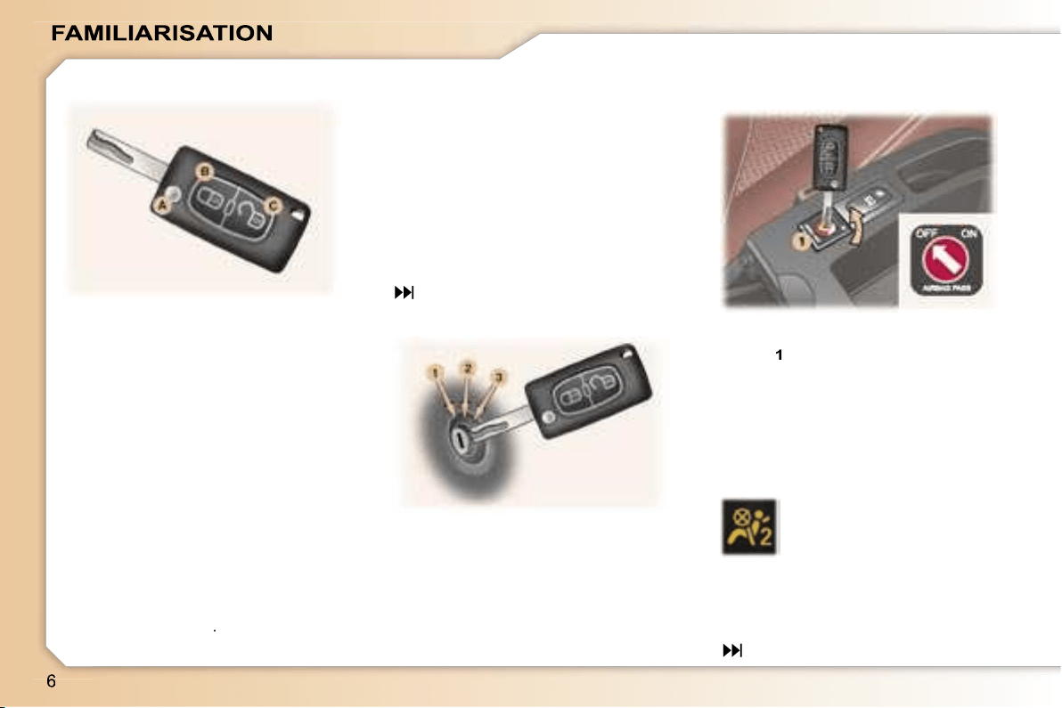
The remote control permits locking,
deadlocking, unlocking and locating
of the vehicle, as well as folding and
unfolding of the exterior mirrors.
The key allows you to switch on the
ignition and mechanically and inde-
pendently operate the lock on the
glove box, the fuel filler cap, the pas-
senger air bag disarming switch and
the child lock.
From the driver’s door, the key allows
you to electrically control the locking,
deadlocking and unlocking of the
doors and tailgate and the folding
and unfolding of the exterior mirrors.
Locking
Press button
B
to lock the vehicle.
This is confirmed by fixed lighting of
the direction indicators for approxi-
mately two seconds.
66
1. STOP position:
The ignition is off.
2. Running position:
The ignition is on and the
accessories can be used.
3. Starting position:
Operates the starter.
With the ignition off
, insert the key
in the passenger air bag disarming
switch
1
, turn it to the
"OFF"
posi-
tion, then remove the key keeping it
in this position.
As soon as you remove the child
seat, turn the air bag switch to the
"ON"
position to activate the air bag
again.
With the ignition switched
on,
illumination of this warn-
ing light indicates that the
passenger air bag is dis-
armed (switch in the
"OFF"
position).
The warning light remains on through-
out the duration of disarming.
Disarming check
*
According to country.
96
THE REMOTE CONTROL KEY
STARTING
DISARMING THE
PASSENGER AIR BAG*
Unlocking
Press button
C
to unlock the vehicle.
This is confirmed by rapid flashing of
the direction indicators for approxi-
mately two seconds.
Unfolding/Folding the key
First press button
A
.
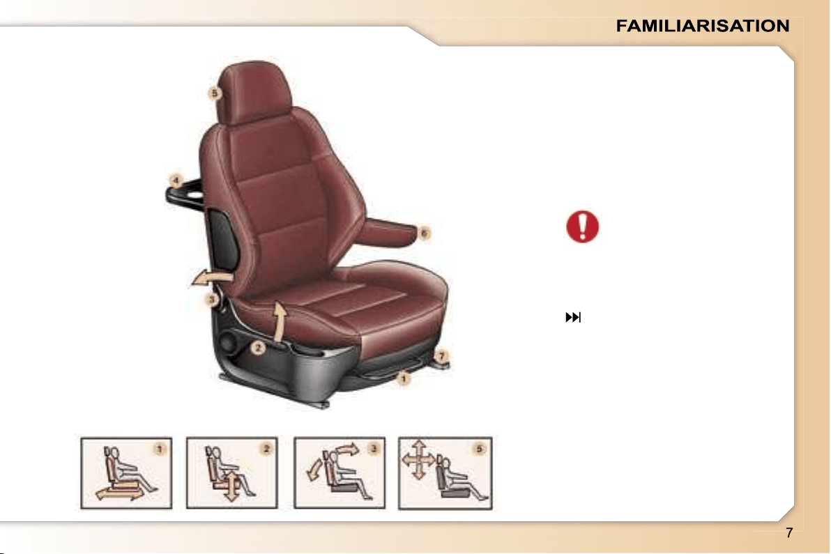
FRONT SEATS
1.
Forwards
/
backwards
adjustment.
2.
Driver or passenger seat height
adjustment.
3.
Seat back angle adjustment.
4.
"Aircraft" style table.
5.
Head restraint height and angle
adjustment.
Never drive with the head
restraints removed.
6.
Front removable armrest.
7.
Storage drawer.
52
–
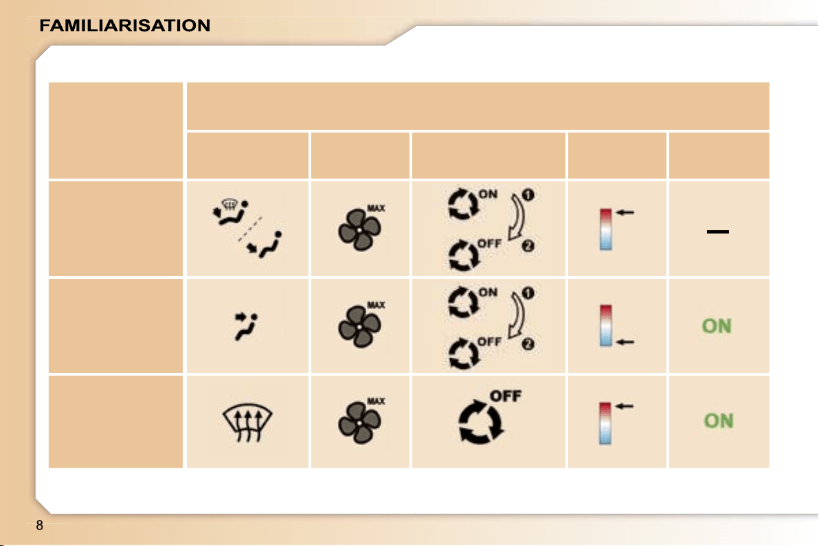
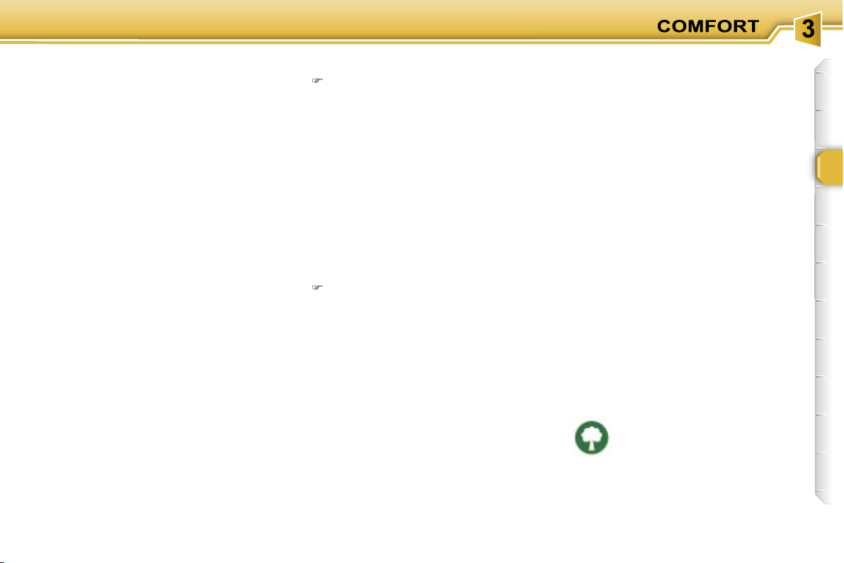
I require...
Manual air conditioning
Air distribution
Air flow
Air recirculation/Intake
of exterior air
Temperature
Manual AC
HOT
COLD
DEMISTING
DE-ICING
RECOMMENDED INTERIOR SETTINGS
48
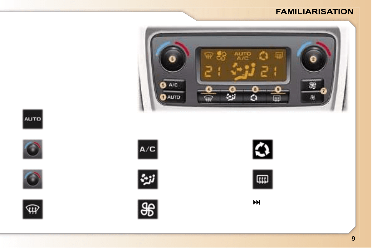
1.
Automatic comfort
programme.
DUAL ZONE AUTOMATIC AIR
CONDITIONING
The driver and his front passenger
can each adjust the temperature to
suit their requirements.
It is preferable to use the automatic
mode which optimises all of the func-
tions: temperature, air flow, air distri-
bution and air recirculation.
2.
Driver’s temperature
adjustment.
3.
Passenger’s
temperature
adjustment.
4.
Automatic visibility
programme.
5.
Air conditioning
On/Off.
6.
Air distribution
adjustment.
7.
Air flow adjustment.
8.
Air intake/Air
recirculation.
9.
Rear screen and
mirrors demisting.
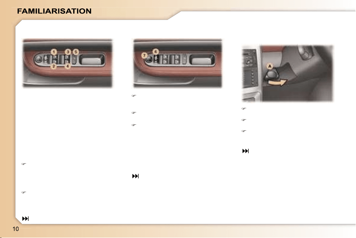
Move switch
6
to the right or to
the left to select the mirror to be
adjusted.
Move switch
7
in all four directions
to adjust.
Return switch
6
to the centre
position.
When parking the vehicle, the mir-
rors can be folded back electrically
by pulling switch
6
rearwards or auto-
matically on locking the vehicle using
the remote control or the key.
When stationary, pull handle
A
to
unlock the steering wheel.
Adjust the height and depth of the
steering wheel.
Lock it by pushing handle
A
in
fully.
51
1. Driver’s electric window.
2. Passenger’s electric window.
3. Rear right electric window.
4. Rear left electric window.
5. Disarming the rear window
switches.
70
50
Manual operation:
Press or pull the switch lightly.
The window stops as soon as the
switch is released.
ELECTRIC WINDOWS ELECTRIC MIRRORS STEERING WHEEL HEIGHT
AND DEPTH ADJUSTMENT
Automatic operation:
Press or pull the switch firmly. One
touch completely opens or closes
the window.
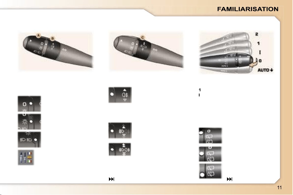
Front
2
Rapid wipe.
1
Normal wipe.
I
Intermittent wipe.
0
Off.
AUTO
Automatic wipe
or single wipe.
Wash-wipe: pull the stalk towards you.
The position is indicated on the in-
strument panel by the corresponding
indicator light.
75
Front and rear lights (ring A)
Lights off.
Side lights.
Dipped/Main beam
headlamps.
Rear fog lamp (rotation
of the ring forwards)
Front fog lamps (first
rotation of the ring for-
wards)
Front fog lamps and
rear fog lamp (second
rotation of the ring for-
wards).
Switching off: rotation of the ring
rearwards.
Automatic switching on of
lights
Activate or deactivate the
function from the multifunc-
tion display configuration
menu.
Vehicles fitted with a rear fog
lamp (ring B)
Vehicles fitted with front fog
lamps and a rear fog lamp
(ring C)
Rear
Off.
Intermittent wipe.
Wash-wipe.
78
LIGHTS STALK WINDSCREEN WIPERS
STALK

1.
Function Selection/Off.
2.
Decreasing of the speed.
3.
Increasing of the speed.
4.
Activation/Deactivation of the
system.
The values must be set with the en-
gine running.
CRUISE CONTROL
102
104
106
The cruise control or speed limiter
function appears on the instrument
panel when it is activated.
Pressing the button enables you to
alternate between the activated func-
tion display and the distance record-
er displays.
SPEED LIMITER
1.
Function Selection/Off.
2.
Storing of a speed/Decreasing
of the stored speed.
3.
Storing of a speed/Increasing of
the stored speed.
4.
Deactivation/Reactivation of the
cruise control.
In order to be stored or activated,
the vehicle speed must be above
25 mph (40 km/h), with at least fourth
gear engaged on the manual gear-
box (second gear on the automatic
gearbox).
Instrument panel display
"PORSCHE TIPTRONIC-
SYSTEM" AUTOMATIC
GEARBOX
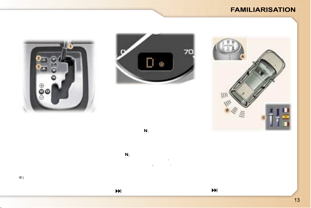
1.
Gear lever.
2.
"SPORT"
button
3.
"SNOW"
button.
99
Move the lever in the gate to select
one of the positions.
Once the position has been selected,
the corresponding indicator light
appears on the instrument panel
display.
A.
Switching on.
B.
Detection.
C.
Activation/Deactivation.
Activate or deactivate the
system from the multifunction
display configuration menu.
When reverse gear is engaged, you
are guided by an audible signal and
a graphic, depending on the multi-
function display, during the reversing
manoeuvre.
108
Gear selection gate
VISUAL AND AUDIBLE REAR
PARKING ASSISTANCE
Instrument panel display
P:
Park.
R:
Reverse.
N:
Neutral.
D:
Drive.
M:
Manual mode.
S:
Sport programme.
:
Snow programme.
1 2 3 4 5* 6*:
gears engaged.
Starting the engine
With the handbrake applied, select
position
P
or
N
.
Switch on the ignition.
Moving off
With the engine running, in position
P
or
N
,
with your foot on the brake,
release the handbrake
.
Select position
R
,
D
or
M
.
Gradually release the brake pedal;
the vehicle moves off immediately.
* According to model.
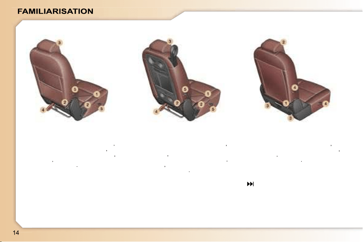
Manoeuvring a side seat:
- forwards-backwards adjustment
(1)
,
- seat back angle adjustment
(2)
,
- head restraint height adjustment
(3)
,
- folding
(4)
,
- removal/refitting
(5)
.
Manoeuvring a centre seat:
- forwards-backwards adjustment
(1)
,
- seat back angle adjustment, table
position
(2)
,
- head restraint height adjustment
(3)
,
- folding
(4)
,
- removal/refitting
(5)
.
Manoeuvring an additional seat:
- seat back angle adjustment
(1)
,
- head restraint height adjustment
(2)
,
- folding
(3)
,
- removal/refitting
(4)
.
54
REAR SEATS
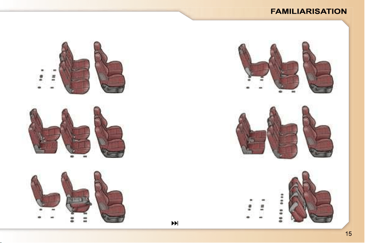
SEAT MODULARITY AND DIFFERENT CONFIGURATIONS
5 seats
5 seats with centre seat in row 3
6 seats with one additional seat
7 seats with two additional seats
Transportation of long objects with table position
Loading of a large volume
57
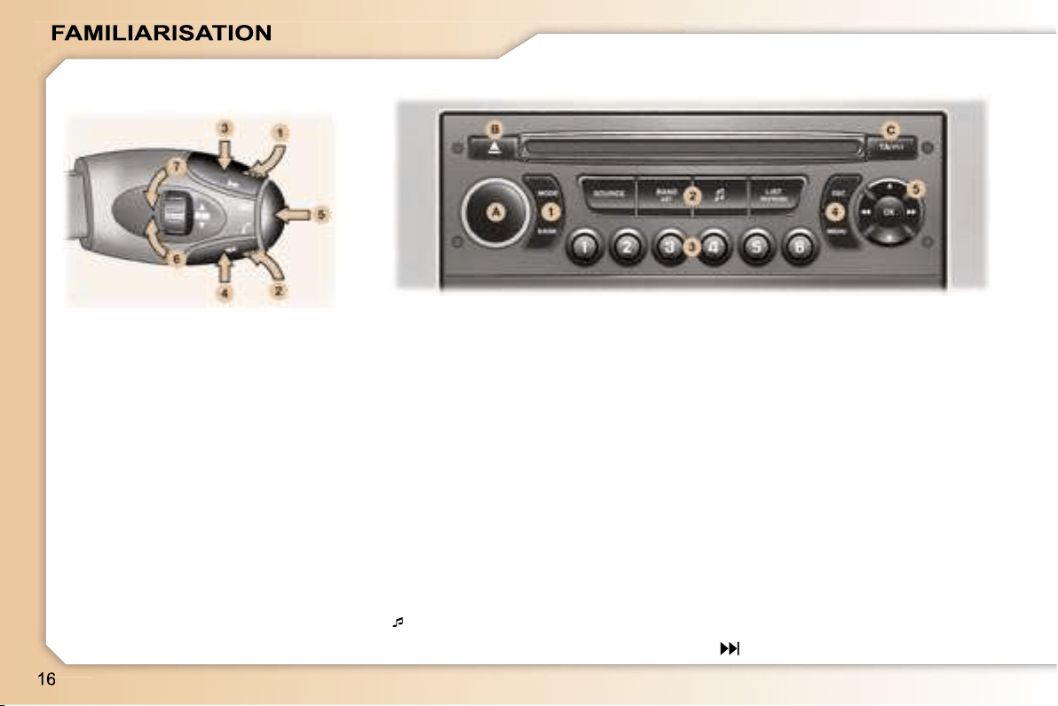
Volume adjustment
1.
Increase by pressing the back
2.
Decrease by pressing the back
1+2.
Cutting off/Restoring of the sound
LIST REFRESH: displaying and up-
dating of the list of stations received,
of the tracks on the CD.
RD4 CONTROL PANEL
Button (A)
ON/OFF and volume adjustment.
AUDIO REMOTE CONTROL
STALK
Search/Selection by pressing
3.
Higher radio frequency - CD/CD
changer: next track
4.
Lower radio frequency - CD/CD
changer: previous track
Sound sources
5.
Change of sound source
Access to the telephone displays
Selection of stations/CD changer
CD by rotation
6.
Higher stored station - Next CD
7.
Lower stored station - Previous
CD
Button (B)
CD eject.
Keypad (1)
MODE: changing of the display of the
permanent application (audio equip-
ment, trip computer, ...).
DARK: 1st press: black screen under
the banner - 2nd press: completely
black screen - 3rd press: return to
the display.
Keypad (2)
SOURCE: change of source between
radio, CD, CD changer.
BAND AST: selection of the frequen-
cy wavebands.
: access to the musical ambience
settings.
Keypad (3)
Storing of the radio station.
Selection of the stored station, of the
CD in relation to the position in the
CD changer.
Keypad (4)
ESC (Escape): cancellation of the
operation in progress.
MENU: displaying of the general
operation in progress.
operation in progress.
menu.
Keypad (5)
Navigator.
Button (C)
TA: traffic information priority on/off.
PTY: access to the search by type of
programme.
165
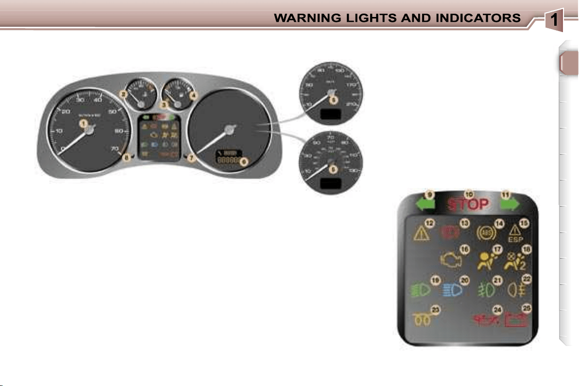
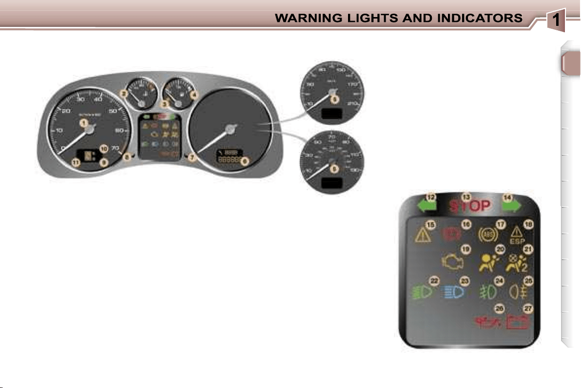
17
1.
Rev counter.
2.
Coolant temperature indicator.
3.
Low fuel level warning light.
4.
Fuel gauge.
5.
Speedometer.
6.
Service indicator, oil level
indicator, distance recorder and
cruise control/speed limiter.
7.
Trip recorder zero reset button.
8.
Lighting rheostat button.
9.
Left-hand direction indicator.
10.
Central STOP warning light.
11.
Right-hand direction indicator.
12.
Service warning light.
13.
Handbrake, brake fluid level
and electronic brake force
distribution warning light.
14.
Anti-lock braking system (ABS)
warning light.
15.
Electronic stability control
(ESP/ASR) warning light.
16.
Emission control system
warning light.
17.
Air bags warning light.
18.
Passenger air bag disarmed
indicator light*.
19.
Dipped beam headlamps
indicator light.
20.
Main beam headlamps indicator
light.
21.
Front fog lamps indicator light.
22.
Rear fog lamp indicator light.
23.
Diesel engine preheating light.
24.
Engine oil pressure warning light*.
25.
Battery charge warning light*.
PETROL/DIESEL INSTRUMENT PANEL DIALS: MANUAL
GEARBOX
* According to country.
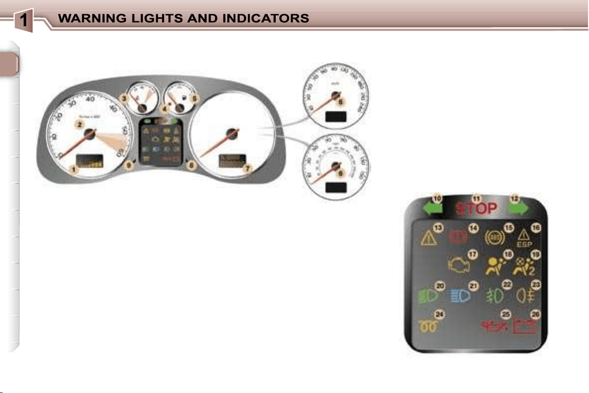
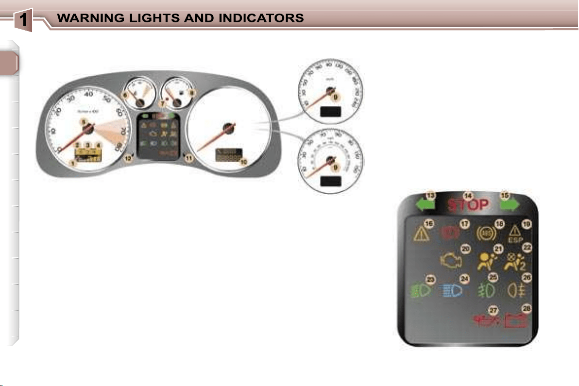
18
1.
Engine oil temperature indicator.
2.
Rev counter.
3.
Coolant temperature indicator.
4.
Low fuel level warning light.
5.
Fuel gauge.
6.
Speedometer.
7.
Service indicator, oil level
indicator, distance recorder and
cruise control/speed limiter.
8.
Trip recorder zero reset button.
9.
Lighting rheostat button.
10.
Left-hand direction indicator.
11.
Central STOP warning light.
12.
Right-hand direction indicator.
13.
Service warning light.
14.
Handbrake, brake fluid level
and electronic brake force
distribution warning light.
15.
Anti-lock braking system (ABS)
warning light.
16.
Electronic stability control
(ESP/ASR) warning light.
17.
Emission control system
warning light.
18.
Air bags warning light.
19.
Passenger air bag disarmed
indicator light*.
20.
Dipped beam headlamps
indicator light.
21.
Main beam headlamps indicator
light.
22.
Front fog lamps indicator light.
23.
Rear fog lamp indicator light.
24.
Diesel engine pre-heat indicator
light.
25.
Engine oil pressure warning light*.
26.
Battery charge warning light*.
PETROL-DIESEL SPORT INSTRUMENT PANEL DIALS: MANUAL
GEARBOX
* According to country.
19
1.
Rev counter.
2.
Coolant temperature indicator.
3.
Low fuel level warning light.
4.
Fuel gauge.
5.
Speedometer.
6.
Service indicator, oil level
indicator, distance recorder and
cruise control/speed limiter.
7.
Trip recorder zero reset button.
8.
Lighting rheostat button.
9.
Snow programme indicator light.
10.
Sport programme indicator light.
11.
Gear lever position indicator.
12.
Left-hand direction indicator.
13.
Central STOP warning light.
14.
Right-hand direction indicator.
15.
Service warning light.
16.
Handbrake, brake fluid level
and electronic brake force
distribution warning light.
17.
Anti-lock braking system (ABS)
warning light.
18.
Electronic stability control
(ESP/ASR) warning light.
19.
Emission control system
warning light.
20.
Air bags warning light.
21.
Passenger air bag disarmed
indicator light*.
22.
Dipped beam headlamps
indicator light.
23.
Main beam headlamps indicator
light.
24.
Front fog lamps indicator light.
25.
Rear fog lamp indicator light.
26.
Engine oil pressure warning
light*.
27.
Battery charge warning light*.
PETROL INSTRUMENT PANEL DIALS: AUTOMATIC GEARBOX
* According to country.
20
1.
Engine oil temperature indicator.
2.
Sport programme indicator light.
3.
Gear lever position indicator.
4.
Snow programme indicator light.
5.
Rev counter.
6.
Coolant temperature indicator.
7.
Low fuel level warning light.
8.
Fuel gauge.
9.
Speedometer.
10.
Service indicator, oil level
indicator, distance recorder and
cruise control/speed limiter.
11.
Trip recorder zero reset button.
12.
Lighting rheostat button.
13.
Left-hand direction indicator.
14.
Central STOP warning light.
15.
Right-hand direction indicator.
16.
Service warning light.
17.
Handbrake, brake fluid level
and electronic brake force
distribution warning light.
18.
Anti-lock braking system (ABS)
warning light.
19.
Electronic stability control
(ESP/ASR) warning light.
20.
Emission control system
warning light.
21.
Air bags warning light.
22.
Passenger air bag disarmed
indicator light*.
23.
Dipped beam headlamps
indicator light.
24.
Main beam headlamps indicator
light.
25.
Front fog lamps indicator light.
26.
Rear fog lamp indicator light.
27.
Engine oil pressure warning light*.
28.
Battery charge warning light*.
PETROL SPORT INSTRUMENT PANEL DIALS: AUTOMATIC
GEARBOX
* According to country.
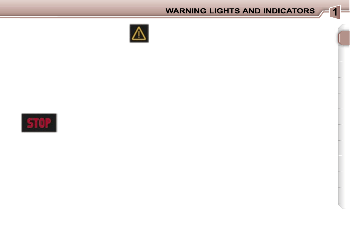
21
OPERATION WARNING
LIGHTS
A permanently lit warning light or
one that flashes with the engine
running, indicates an operating fault
in the relevant unit. Some warning
lights may be linked to buzzers and
a message on the multifunction dis-
play. Do not ignore this warning:
contact a PEUGEOT dealer as soon
as possible.
If the Central STOP warning light
comes on when you are driving,
stop immediately where it is safe
to do so.
Central STOP
warning light
This light comes on
for a few seconds
each time the ignition is switched
on.
It is linked to the "engine oil pres-
sure"*, "low brake fluid level" and
"electronic brake force distribution
fault" warning lights and the coolant
temperature gauge.
Stop immediately if it flashes with
the engine running.
Contact a PEUGEOT dealer.
It also comes on in the event of a
puncture, accompanied by an audible
signal and a message on the multi-
function display locating the wheel
concerned.
Service warning light
This light comes on for a
few seconds each time the
ignition is switched on. If it
remains on or comes on when the
engine is running, accompanied by
an audible signal and a message on
the multifunction display, it indicates
one of the following:
- a battery charge fault*,
- an automatic gearbox operation
fault,
- an engine immobiliser system
fault,
- an engine management system
fault,
- a speed control system fault (cruise
control/speed limiter),
- a rear parking assistance system
fault,
- an automatic switching on of the
lights system fault,
- an automatic headlamp adjustment
system fault,
- a tyre under-inflation detection
system fault,
- a deflated tyre,
- a flat remote control battery,
- one or more door(s) open at a vehicle
speed above 6 mph (10 km/h),
- a low diesel additive reservoir level
(Diesel),
- a lack of engine oil,
- the start of saturation of the particle
emission filter (Diesel) due to
exceptionally prolonged urban
driving conditions: low speed, long
traffic jams, ...
In order to regenerate the filter, you
are advised to drive at a speed of
40 mph (60 km/h) or above for at
least five minutes (until the warning
light is switched off) as soon as
possible, when traffic conditions
permit. If the warning light remains
on, contact a PEUGEOT dealer.
During regeneration of the particle
emission filter, relay noise may be
heard from underneath the fascia.
- the presence of water in the diesel
filter (Diesel)*.
Risk of damage to the injection
system.
Contact a PEUGEOT dealer as
soon as possible.
- a low coolant level**.
Stop immediately.
Warning:
wait for the engine to
cool before topping up the level.
The cooling system is pressurised.
In order to avoid any risk of scalding,
unscrew the cap by two turns to
allow the pressure to drop. When
the pressure has dropped, remove
the cap and top up the level.
Contact a PEUGEOT dealer.
* According to country.
** According to engine.
22
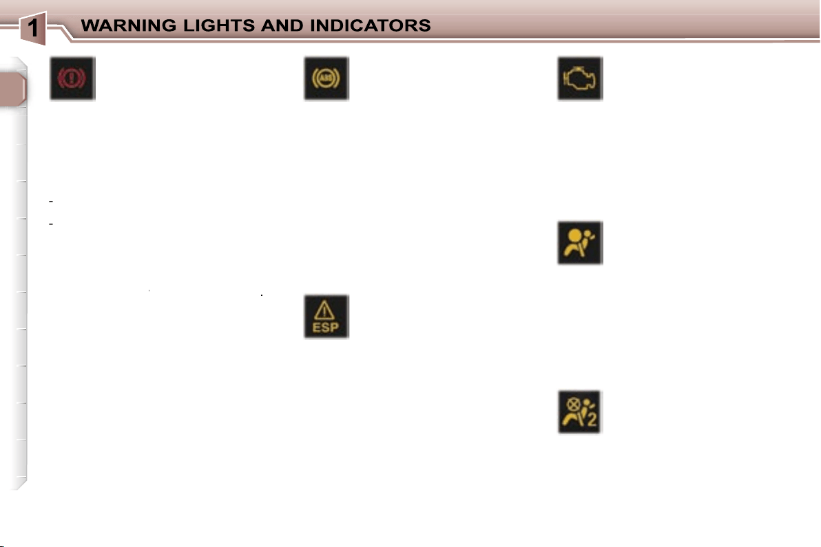
Electronic stability
programme (ESP/ASR)
warning light
This comes on for a few
seconds each time the igni-
tion is switched on.
If the light remains on or comes on
when the engine is running and the
vehicle is moving, it is accompanied
by an audible signal and a message
on the multifunction display; contact
a PEUGEOT dealer.
When the engine is running and the
vehicle is moving, it flashes if the
system is activated.
It is lit continuously when the system
is disarmed.
Emission control system
warning light
This comes on each time
the ignition is switched on.
It should switch off a few seconds af-
ter the engine is started.
If the light comes on when the engine
is running, accompanied by an audible
signal and a message on the multifunc-
tion display, this indicates a malfunc-
tion of the emission control system.
Contact a PEUGEOT dealer as soon
as possible.
Air bag warning light
This comes on for a few
seconds each time the igni-
tion is switched on.
Illumination of this warning light, with
the engine running, is accompanied by
an audible signal and a message on
the multifunction display indicating:
- a fault in the front air bags,
or
- a fault in the side air bags or curtain
air bags.
Contact a PEUGEOT dealer.
Passenger air bag
disarmed indicator light*
This comes on for a few
seconds each time the igni-
tion is switched on.
If the passager air bag is disarmed,
the indicator light remains on.
In all cases, if the indicator light flash-
es, contact a PEUGEOT dealer.
Handbrake, low brake
fluid level and electronic
brake force distribution
fault warning light.
Linked to the central
STOP
warning
light.
This comes on for a few seconds each
time the ignition is switched on.
Illumination of this light is accompanied
by an audible signal and a message on
the multifunction display indicating:
-
that the handrake is applied or has
not been released correctly,
-
an excessive drop in the brake fluid
level (if the light remains on even
with the handbrake released),
- a malfunction of the electronic
brake force distribution, if linked to
the ABS warning light.
Stop immediately
in the last two cases
Stop immediately
Stop immediately
.
Contact a PEUGEOT dealer.
Anti-lock braking system
(ABS) warning light
This light comes on for a
few seconds each time the
ignition is switched on.
If it remains on or comes on above
8 mph (12 kmh), this indicates a mal-
function of the ABS.
However, the vehicle retains conven-
tional servo-assisted braking.
Illumination of this light is accompa-
nied by an audible signal and a mes-
sage on the multifunction display.
Contact a PEUGEOT dealer.
23
Battery charge warning
light*
This comes on for a few
seconds each time the igni-
tion is switched on.
If it comes on with the engine run-
ning, it is accompanied by an audible
signal and a message on the multi-
function display.
According to country, this warning
light may be replaced by the service
warning light.
It can indicate:
- faulty operation of the charging
circuit,
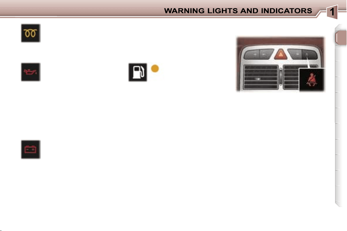
Low fuel level
warning light
This comes on for a
few seconds each
time the ignition is
switched on.
When this light comes on with the en-
gine running, it is accompanied by an
audible signal and a message on the
multifunction display.
When the warning light comes on, you
have enough fuel left to drive approxi-
mately
30 miles (50 km)
. The tank ca-
pacity is approximately 60 litres.
Diesel pre-heat light
This comes on for a few
seconds each time the igni-
tion is switched on.
Wait until it goes out before trying the
starter.
Engine oil pressure
warning light*
Linked to the central
STOP
warning light.
If it comes on with the engine run-
ning, it is accompanied by an audible
signal and a message on the multi-
function display.
Stop immediately.
If there is a lack of oil in the lubrica-
tion circuit, top up the level.
Contact a PEUGEOT dealer without
delay.
Engine oil pressure warning*
Linked to the central
STOP
warning
light.
When the engine is running, the en-
gine oil pressure warning message is
accompanied by an audible signal.
Stop immediately.
If there is a lack of oil in the lubrica-
tion circuit, top up the level.
Contact a PEUGEOT dealer as soon
as possible.
When the ignition is switched on, the
light comes on if the driver and/or the
front passenger has not fastened his
seat belt.
With the engine running and the
doors closed, the light switches off
automatically after 30 seconds.
If a front seat belt is unfastened:
- below 12 mph (20 km/h), the light
comes on constantly,
- above 12 mph (20 km/h) and for
two minutes, the light flashes
accompanied by an audible signal
of increasing volume. Once these
two minutes have elapsed, the light
remains on until the driver and/or
the front passenger fastens his
seat belt.
Seat belt unfastened/not fastened
warning light
* According to country.
- loose battery or starter terminals,
- a cut or slack alternator belt,
- an alternator fault.
Contact a PEUGEOT dealer.
24
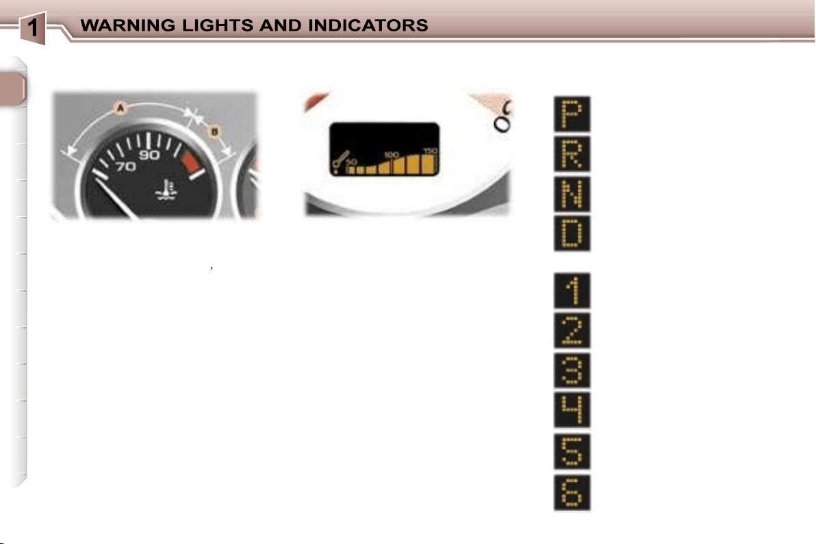
When the needle is in zone
A
, the
temperature is correct.
When the needle is in zone
B
,
the tem-
perature is too high. The central
STOP
warning light flashes,
accompanied by
an audible signal and a message on
the multifunction display.
You must stop immediately.
Warning:
wait for the engine to cool
before topping up the level.
The cooling system is pressurised.
In order to avoid any risk of scalding,
unscrew the cap two turns to allow
the pressure to drop.
When the pressure has dropped, re-
move the cap and top up the level.
Contact a PEUGEOT dealer.
Park
Automatic gearbox lever
positions indicator
Reverse
Neutral
Drive
Manual mode:
1st gear engaged
2nd gear engaged
3rd gear engaged
4th gear engaged
When the engine is running, this indi-
cates the temperature of the oil.
The temperature is too high if the
maximum graduation is reached.
You must stop immediately.
Contact a PEUGEOT dealer.
Coolant temperature indicator
Engine oil temperature
indicator
* According to model.
5th gear* engaged
6th gear* engaged
25
In the event of under-revving or over-
revving, the gear selected flashes for
a few seconds, then the actual gear
engaged is displayed.
This comes on when the
"SPORT"
programme on
the automatic gearbox is
selected.
This comes on when the
"SNOW"
programme on
the automatic gearbox is
selected.
Automatic gearbox indicator
lights
"SNOW" indicator light
This is displayed if a gear is
not engaged correctly (selec-
tor between two positions).
"SPORT" indicator light
Invalid value during manual
operation
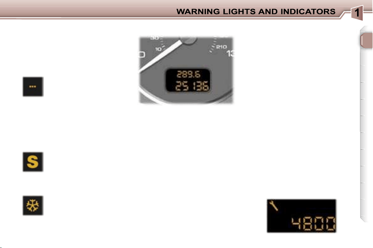
After switching on the ignition, three
functions are shown in succession:
- service indicator,
- engine oil level indicator,
- total distance recorder (total and
trip distances).
Note:
the total and trip distances are
displayed for 30 seconds when the
ignition is switched off, on opening
the driver’s door, as well as on lock-
ing and unlocking the vehicle.
It also displays the information re-
lating to the cruise control or speed
limiter, when either of these is acti-
vated (see corresponding section).
Service indicator
This indicates when the next service
is due in accordance with the manu-
facturer’s servicing schedule.
The point at which the next service
is due is calculated from the last indi-
cator zero reset (see corresponding
section). It is determined by two pa-
rameters:
- the distance travelled,
- the time which has elapsed since
the last service.
Note:
the distance remaining before
the next service may be weighted by
the time factor, depending on the us-
er’s driving habits.
Operation
For 5 seconds after the ignition is
switched on, the spanner symbolis-
ing the servicing operations comes
on; the distance recorder display in-
dicates the number of miles [kilome-
tres] (rounded off) remaining until the
next service.
Example:
4,800 miles/km remain
before the next service. For five sec-
onds after the ignition is switched on,
the display indicates:
INSTRUMENT PANEL DISPLAY
26
5 seconds after the ignition was
switched on, the distance recorder
resumes its normal operation and
the display indicates the total and trip
distance.
Your PEUGEOT dealer carries out
this operation after each service.
However, if you carry out the service
yourself, the re-set procedure is as
follows:
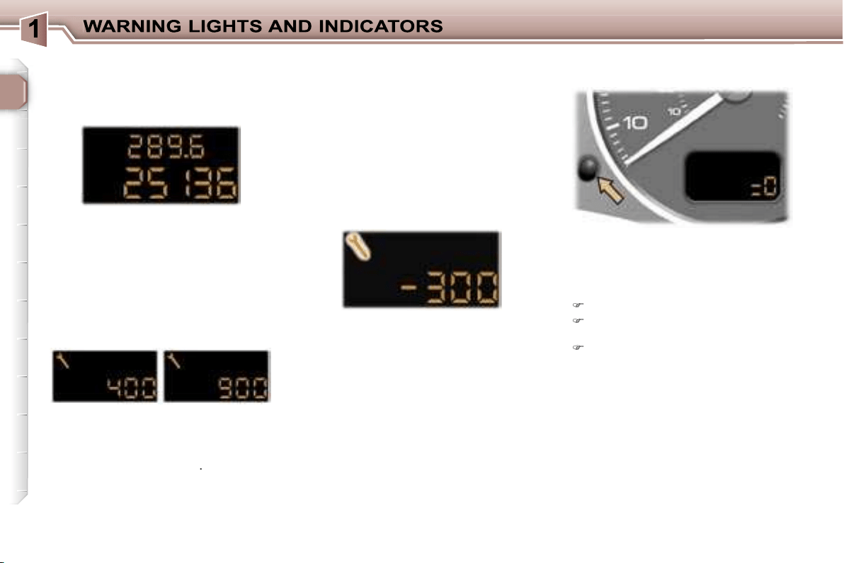
Switch off the ignition,
Press and hold the trip recorder
re-set button,
Switch on the ignition.
The display begins a countdown.
When the display shows
"=0"
, re-
lease the button; the service symbol
disappears.
Important:
after this operation, if you
wish to disconnect the battery, lock
the vehicle and wait for at least five
minutes, otherwise the zero re-set
will not be registered.
The service is overdue.
The service spanner flashes for 5 sec-
onds after the ignition is switched on.
Example:
the service is overdue by
300 miles/km, your vehicle must be
serviced as soon as possible.
For 5 seconds after the ignition is
switched on, the display indicates:
5 seconds after the ignition was
switched on, the distance recorder
resumes its normal operation and
the service spanner remains lit. The
display indicates the total and trip
distance.
Note:
the service spanner may also
come on if more than two years have
elapsed since the last service.
The distance remaining to the
next service is less than 500 miles
(1,000 km).
Example:
400 miles (900 km) re-
main before the next service.
For 5 seconds after the ignition is
switched on, the indicator displays:
5 seconds after the ignition was
switched on, the distance recorder
resumes its normal operation and
the spanner remains lit
.
It indicates that a service must be
carried out soon. The display indi-
cates the total and trip distance.
Service indicator zero reset
27
With the lights on, press the button
to vary the intensity of the lighting of
the instruments and controls. When
the lighting reaches the minimum (or
maximum) setting, release the button
then press it again to increase (or re-
duce) the brightness.
As soon as the lighting is of the re-
quired brightness, release the button.
With the ignition on, press the button
until the zeros appear.
Pressing the button enables you to
alternate between the distance re-
corder and cruise control or speed
limiter displays, when either of these
is activated.
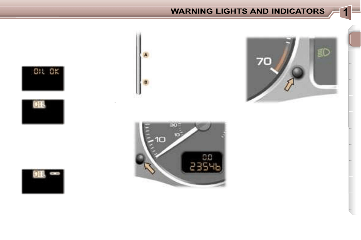
Engine oil level indicator
When the ignition is switched on, the
engine oil level is indicated for a few
seconds, after the service information.
Oil level correct
Oil level gauge fault
Flashing of
"OIL --"
indicates a malfunc-
tion of the engine oil
level gauge.
Contact a PEUGEOT dealer.
The level read will only be correct
if the vehicle is on level ground
and the engine has been off for
more than 15 minutes.
Flashing of
"OIL"
,
linked with the serv-
ice warning light,
accompanied by an
audible signal and
a message on the
multifunction display, indicates a lack
of oil which could damage the engine.
If the lack of oil is confirmed by a
check using the dipstick, it is essen-
tial that the level is topped up.
Lack of oil
Dipstick
There are 2 marks on the
dipstick:
- never exceed level A,
- in position B, top up the
level via the oil filler cap,
using the type of oil suited
to your engine.
A
= max.
B
= min.
Trip recorder zero reset
button
Lighting rheostat

25
In the event of under-revving or over-
revving, the gear selected flashes for
a few seconds, then the actual gear
engaged is displayed.
This comes on when the
"SPORT"
programme on
the automatic gearbox is
selected.
This comes on when the
"SNOW"
programme on
the automatic gearbox is
selected.
Automatic gearbox indicator
lights
"SNOW" indicator light
This is displayed if a gear is
not engaged correctly (selec-
tor between two positions).
"SPORT" indicator light
Invalid value during manual
operation
After switching on the ignition, three
functions are shown in succession:
- service indicator,
- engine oil level indicator,
- total distance recorder (total and
trip distances).
Note:
the total and trip distances are
displayed for 30 seconds when the
ignition is switched off, on opening
the driver’s door, as well as on lock-
ing and unlocking the vehicle.
It also displays the information re-
lating to the cruise control or speed
limiter, when either of these is acti-
vated (see corresponding section).
Service indicator
This indicates when the next service
is due in accordance with the manu-
facturer’s servicing schedule.
The point at which the next service
is due is calculated from the last indi-
cator zero reset (see corresponding
section). It is determined by two pa-
rameters:
- the distance travelled,
- the time which has elapsed since
the last service.
Note:
the distance remaining before
the next service may be weighted by
the time factor, depending on the us-
er’s driving habits.
Operation
For 5 seconds after the ignition is
switched on, the spanner symbolis-
ing the servicing operations comes
on; the distance recorder display in-
dicates the number of miles [kilome-
tres] (rounded off) remaining until the
next service.
Example:
4,800 miles/km remain
before the next service. For five sec-
onds after the ignition is switched on,
the display indicates:
INSTRUMENT PANEL DISPLAY

26
5 seconds after the ignition was
switched on, the distance recorder
resumes its normal operation and
the display indicates the total and trip
distance.
Your PEUGEOT dealer carries out
this operation after each service.
However, if you carry out the service
yourself, the re-set procedure is as
follows:
Switch off the ignition,
Press and hold the trip recorder
re-set button,
Switch on the ignition.
The display begins a countdown.
When the display shows
"=0"
, re-
lease the button; the service symbol
disappears.
Important:
after this operation, if you
wish to disconnect the battery, lock
the vehicle and wait for at least five
minutes, otherwise the zero re-set
will not be registered.
The service is overdue.
The service spanner flashes for 5 sec-
onds after the ignition is switched on.
Example:
the service is overdue by
300 miles/km, your vehicle must be
serviced as soon as possible.
For 5 seconds after the ignition is
switched on, the display indicates:
5 seconds after the ignition was
switched on, the distance recorder
resumes its normal operation and
the service spanner remains lit. The
display indicates the total and trip
distance.
Note:
the service spanner may also
come on if more than two years have
elapsed since the last service.
The distance remaining to the
next service is less than 500 miles
(1,000 km).
Example:
400 miles (900 km) re-
main before the next service.
For 5 seconds after the ignition is
switched on, the indicator displays:
5 seconds after the ignition was
switched on, the distance recorder
resumes its normal operation and
the spanner remains lit
.
It indicates that a service must be
carried out soon. The display indi-
cates the total and trip distance.
Service indicator zero reset

27
With the lights on, press the button
to vary the intensity of the lighting of
the instruments and controls. When
the lighting reaches the minimum (or
maximum) setting, release the button
then press it again to increase (or re-
duce) the brightness.
As soon as the lighting is of the re-
quired brightness, release the button.
With the ignition on, press the button
until the zeros appear.
Pressing the button enables you to
alternate between the distance re-
corder and cruise control or speed
limiter displays, when either of these
is activated.
Engine oil level indicator
When the ignition is switched on, the
engine oil level is indicated for a few
seconds, after the service information.
Oil level correct
Oil level gauge fault
Flashing of
"OIL --"
indicates a malfunc-
tion of the engine oil
level gauge.
Contact a PEUGEOT dealer.
The level read will only be correct
if the vehicle is on level ground
and the engine has been off for
more than 15 minutes.
Flashing of
"OIL"
,
linked with the serv-
ice warning light,
accompanied by an
audible signal and
a message on the
multifunction display, indicates a lack
of oil which could damage the engine.
If the lack of oil is confirmed by a
check using the dipstick, it is essen-
tial that the level is topped up.
Lack of oil
Dipstick
There are 2 marks on the
dipstick:
- never exceed level A,
- in position B, top up the
level via the oil filler cap,
using the type of oil suited
to your engine.
A
= max.
B
= min.
Trip recorder zero reset
button
Lighting rheostat
28
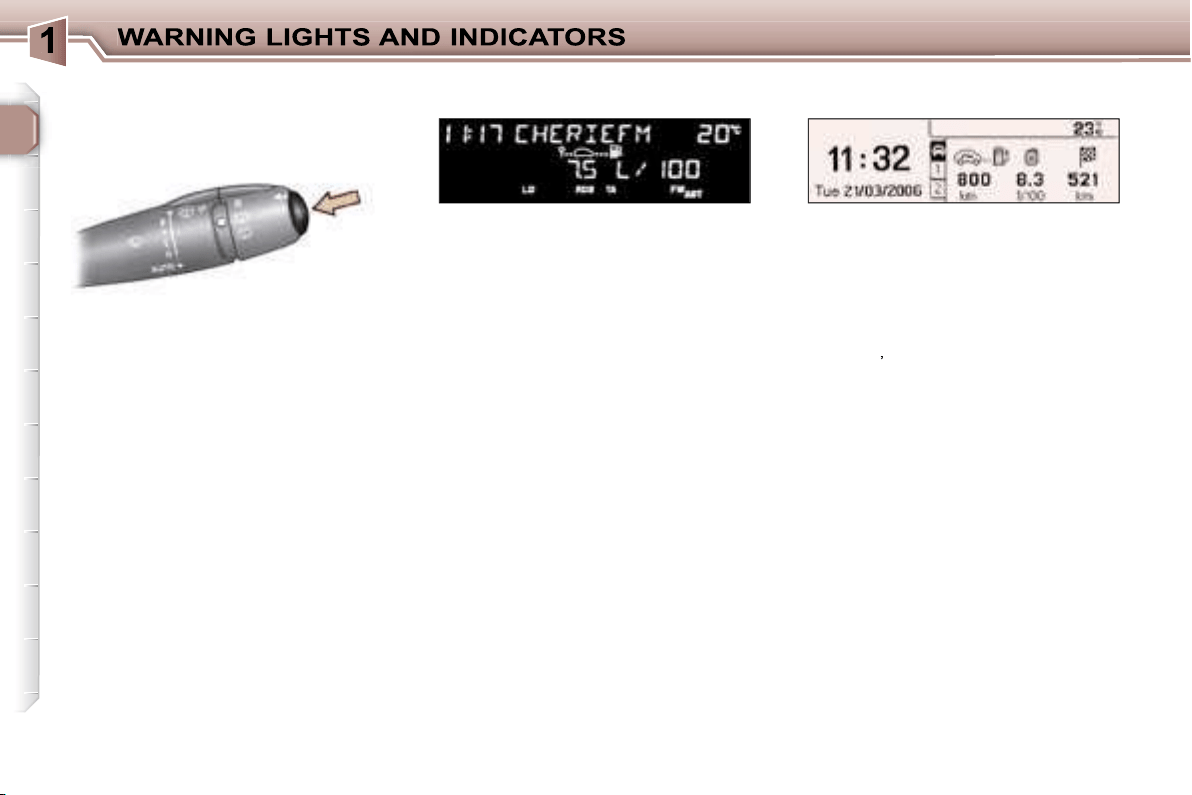
TRIP COMPUTER
Monochrome screens A
- the range,
- the current consumption,
- the distance travelled,
- the average consumption,
- the average speed.
Each time the button on the end of
the
wiper stalk
is pressed, the vari-
ous items of trip computer data are
displayed in succession, depending
on the multifunction display:
Zero reset
Press the stalk for more than two
seconds.
Monochrome screens C
- the
"vehicle"
tab with:
• the range, the current consump-
tion and the distance still to be
driven,
- tab
"1"
(route 1) with:
• the average speed, the average
consumption and the distance
driven calculated over route
"1"
,
- tab
"2"
(route 2) with the same
features for a second route.
Zero reset
When the required route is displayed,
press the button for more than two
seconds.

29
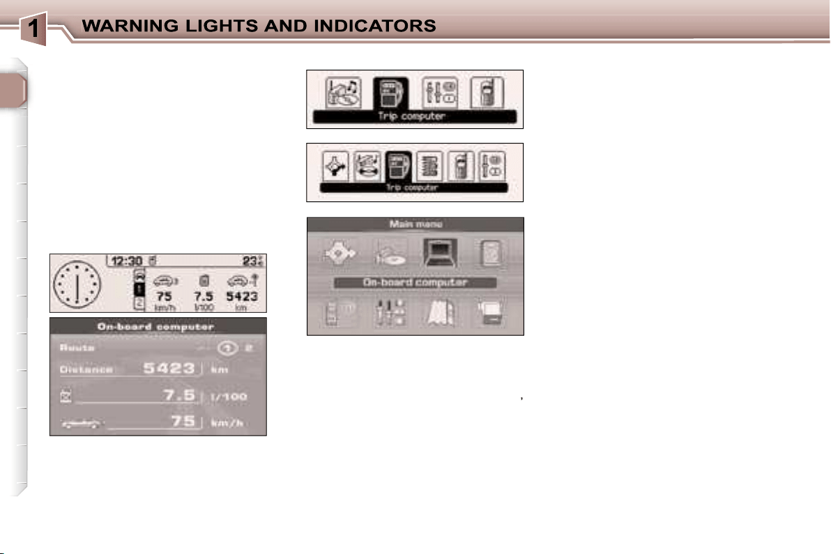
Colour screen DT
- the
"Current information"
with:
• the range,
• the current consumption,
• the distance still to be driven.
-
"Route 1"
with:
• the distance travelled,
• the average consumption,
• the average speed,
-
"Route 2"
with the same features
for a second route.
Monochrome screen CT
-
the
"vehicle"
tab with:
• the range, the current
consumption
and the distance
still to be driven,
- tab
"1"
(route 1) with:
• the average speed, the average
consumption and the distance
driven calculated over route
"1"
-
tab
"2"
(route 2) with the same
features for a second route.
Zero re-set
When the required route is displayed,
press the button for more than two
seconds.
Zero re-set
When the required route is displayed,
press the button for more than two
seconds.
This figure may increase if there is
a change in the style of driving or
the road surface, producing a sig-
nificant drop in current consump-
tion.
When the range is less than 20 miles
(30 km), dashes are displayed. After
filling with at least 5 litres of fuel, the
range is recalculated and is displayed
when it exceeds 62 miles (100 km).
If dashes are displayed for long
periods instead of digits, contact a
PEUGEOT dealer.
Current consumption
This is the average quantity of fuel con-
sumed during the last few seconds.
This function is displayed only when
the vehicle is travelling at a speed
greater than 20 mph (30 km/h).
It can be displayed in litres/100, km/
litre or mpg (refer to on-board com-
puter configuration).
Average consumption
This is the average fuel consumption
since the computer was last set to
zero.
It can be displayed in litres/100, km/
litre or mpg (refer to on-board com-
puter configuration).
Distance travelled
This indicates the distance travelled
since the computer was last set to
zero.
Range
This shows the distance that can still
be covered with the fuel remaining in
the tank in accordance with the av-
erage consumption over the last few
miles (kilometres) driven.
30
The routes
"1"
and
"2"
are independ-
ent but have identical application.
Route
"1"
for example allows you
to make daily calculations and route
"2"
monthly calculations.
Distance remaining to be
travelled
This is the distance remaining to the
final destination. It can either be cal-
culated continuously by the naviga-
tion system if guidance is activated,
or entered by the user.
If the distance is not entered, dashes
are displayed in place of the digits.
Average speed
This is the average speed calculated
since the computer was last set to
zero (with the ignition on).
The routes
Access via the general menu
Screen C
Screen CT
Screen DT
"On-board computer" menu
Press the
"MENU"
button to access
the general menu.
Select the icon
"On-board computer"
,
then validate to access its menu.
Depending on the multifunction dis-
play, this menu offers various choices:
- Enter distance to destination,
- Warning log.
- Status of the functions.
or
- On-board computer configuration.
- Diagnostics,
- Status of the functions.
Enter distance to destination
If guidance has not been activated,
this enables you to enter an approxi-
mate distance to final destination
value, to permit all of the on-board
computer calculations.
Warning log
This summarises the active warning
messages, displaying them in suc-
cession on the multifunction display.
Status of the functions
This summarises the active or not
active status of the functions present
on the vehicle.
On-board computer configuration
This function allows the distance to
the destination to be input (when
guidance is not activated; otherwise
this information is given by the navi-
gation system) and also changing of
the units of measurement (°C or °F,
km and litres or miles and gallons).
The consumption values (current or
average) can be displayed in litres/
100, km/litre or mpg.
Diagnostics
This presents the information relating
to the warning log, as regards the en-
ergy remaining in the back-up battery
and the number of satellites which
can be seen by the GPS system.
31
Presentation
This displays the following information:
- the time,
- the date,
- the outside temperature (this
flashes if there is a risk of ice),
- the status of the accesses (doors,
boot, ...),
- the warning messages (e.g.:
"Emission control system faulty") or
information messages (e.g.: "Auto
lights on"), displayed temporarily,
can be cleared by pressing the
"ESC"
button,
- the trip computer (see corresponding
section).
MONOCHROME SCREEN A
(without RD4 audio equipment)
Parameter configuration
There are three display control buttons:
-
"ESC"
to abandon the operation in
progress,
-
"MENU"
to scroll through the
menus or sub-menus,
-
"OK"
to select the menu or sub-
menu required.
Press the
"MENU"
button to scroll
through the various menus of the
general menu:
- vehicle configuration,
- options,
- display settings,
- languages,
- units.
Press the
"OK"
button to select the
menu required.
General menu
32
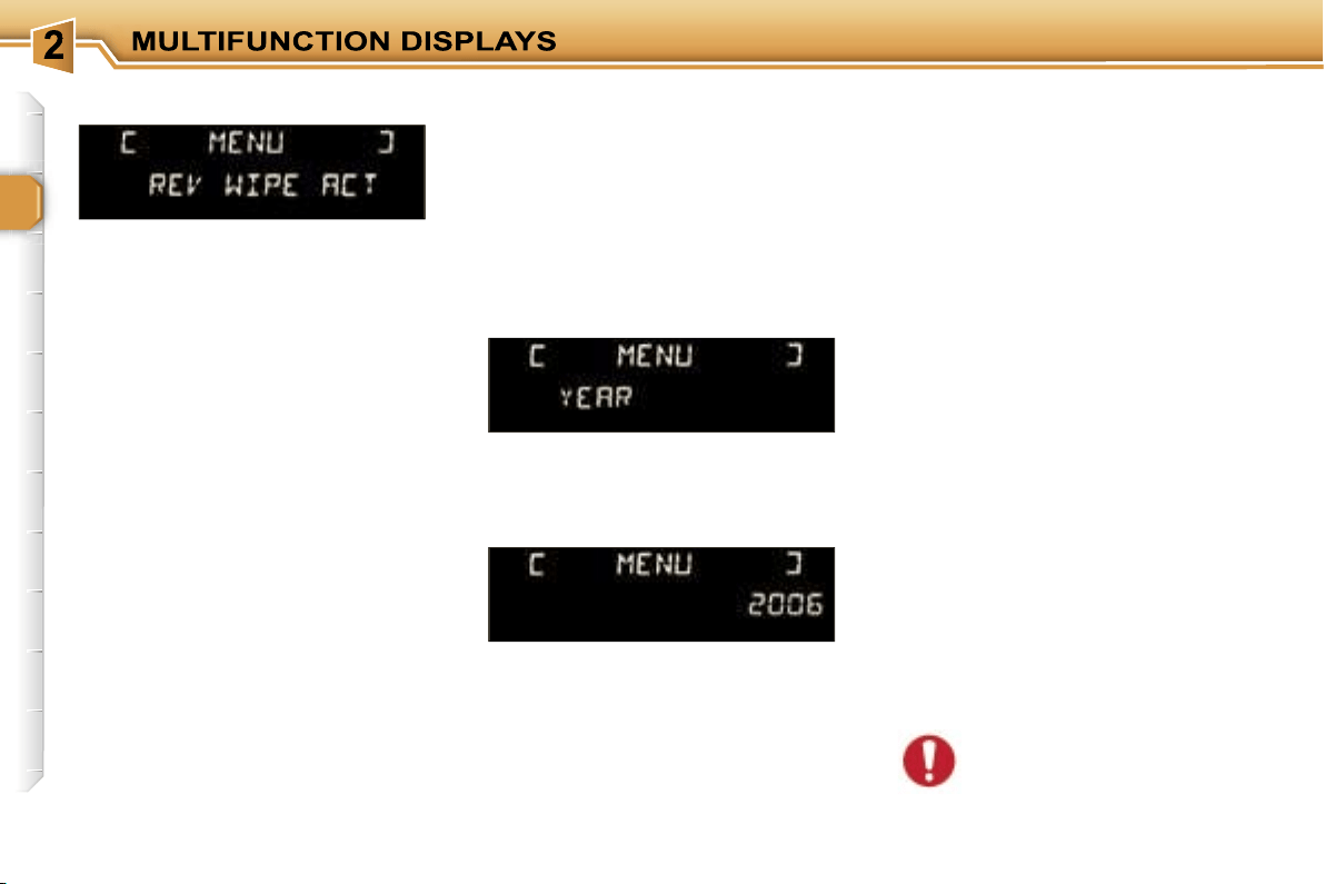
Once the
"Vehicle configuration"
menu
has been selected, you can activate or
deactivate the following equipment:
- wiper linked with reverse gear,
- automatic switching on of the lights,
- "follow-me-home" lighting,
- parking assistance.
Options
Once the "Options" menu has been
selected, you can start diagnostics of
the status of the equipment (active,
not active, faulty).
Languages
Once the "Languages" menu has been
selected, you can change the language
used by the display (Français, Italiano,
Nederlands, Portugues, Portugues-
Brasil, Deutsch, English, Espanol).
Display settings
Once the "Display settings" menu has
been selected, you can gain access
to the following settings:
- year,
- month,
- day,
- hour,
- minutes,
- 12 or 24 hour mode.
Units
Once the "Units" menu has been
selected, you can change the units
of the following parameters:
- temperature (°C or °F),
- fuel consumption (l/100, mpg or km/l).
Once you have selected a setting,
press the
"OK"
button to change its
value.
Wait for approximately ten seconds
without any action to allow the
changed data to be recorded or press
the
"ESC"
button to cancel.
The display then returns to the
normal display.
For safety reasons, configu-
ration of the multifunction
displays by the driver must
take place when stationary.
Vehicle configuration
33
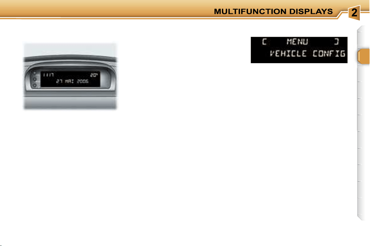
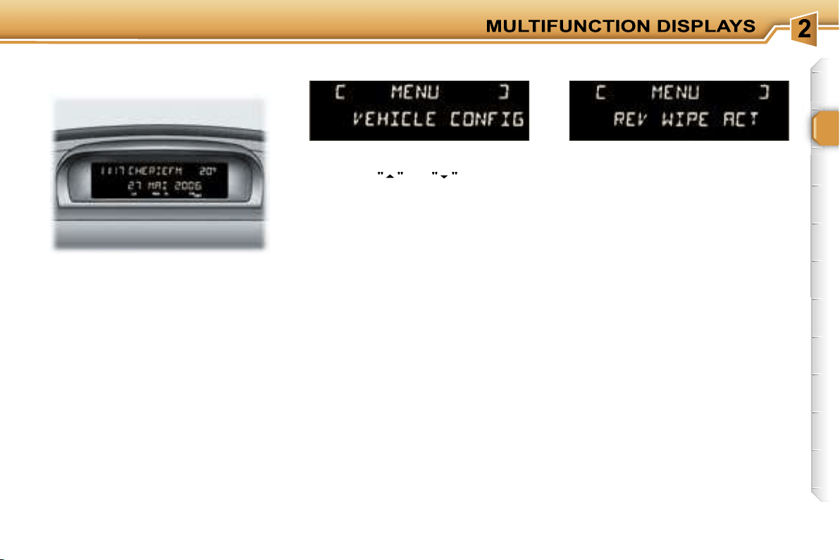
MONOCHROME DISPLAY A
Press the
"MENU"
button to gain
access to the general menu, then
press the
"
"
or
"
"
buttons to
scroll through the following items:
- radio-CD,
- vehicle configuration,
- options,
- display settings,
- languages,
- units.
Press the
"OK"
button to select the
menu required.
Presentation
This displays the following information,
via the RD4 audio equipment control
keypad:
- the time,
- the date,
- the outside temperature (this
flashes if there is a risk of ice),
- the audio source displays (radio,
CD, ...),
- the status of the accesses (doors,
boot, ...),
-
the warning messages (e.g.:
"Emission control system faulty") or
information messages (e.g.: "Auto
lights on"), displayed temporarily, can
be cleared by pressing the
"ESC"
button,
- the trip computer (see corresponding
section).
Radio-CD
With the RD4 audio equipment
switched on, once the "Radio-CD"
menu has been selected, you can
activate or deactivate the functions
linked with the use of the radio (RDS
following, REG mode), the CD or the
CD changer (introscan, random play,
CD repeat).
Once the "Vehicle configuration"
menu has been selected, you can
activate or deactivate the following
equipment:
- rear wiper linked with reverse gear,
- automatic switching on of the
lights,
- "follow-me-home" lighting,
- parking assistance.
Options
Once the "Options" menu has been
selected, you can start diagnostics of
the status of the equipment (active,
not active, faulty).
General menu
Vehicle configuration
34
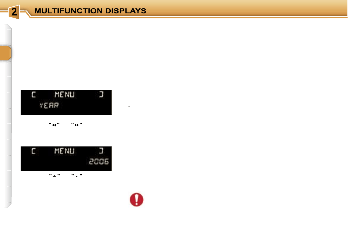
Display settings
Once the "Display settings" menu has
been selected, you can gain access
to the following settings:
- year,
- month,
- day,
- hour,
- minutes,
- 12 or 24 hour mode.
Languages
Once the "Languages" menu has been
selected, you can change the language
used by the display (Français, Italiano,
Nederlands, Portugues, Portugues-
Brasil, Deutsch, English, Espanol).
Units
Once the "Units" menu has been
selected, you can change the units
of the following parameters:
- temperature (°C or °F),
-
fuel consumption (l/100, mpg or km/l).
Once you have selected a setting,
press the
"
"
or
"
"
buttons to
change its value.
Press the
"
"
or
"
"
buttons to
move to the previous or next setting
respectively.
Press the
"OK"
button to record
the change and return to the normal
display or press the
"ESC"
button to
cancel.
For safety reasons, configu-
ration of the multifunction
displays by the driver must
take place when stationary.
35
Presentation
It displays the following information:
- the time,
- the date,
- the exterior temperature (this
flashes if there is a risk of ice),
- the accesses check (doors, boot, ...),
- the warning messages (e.g.:
"Depollution system faulty") or
information messages (e.g.:
"Automatic headlamp lighting
activated"), displayed temporarily,
can be cleared by pressing the
"ESC"
button,
- the trip computer (see correspond-
ing section).
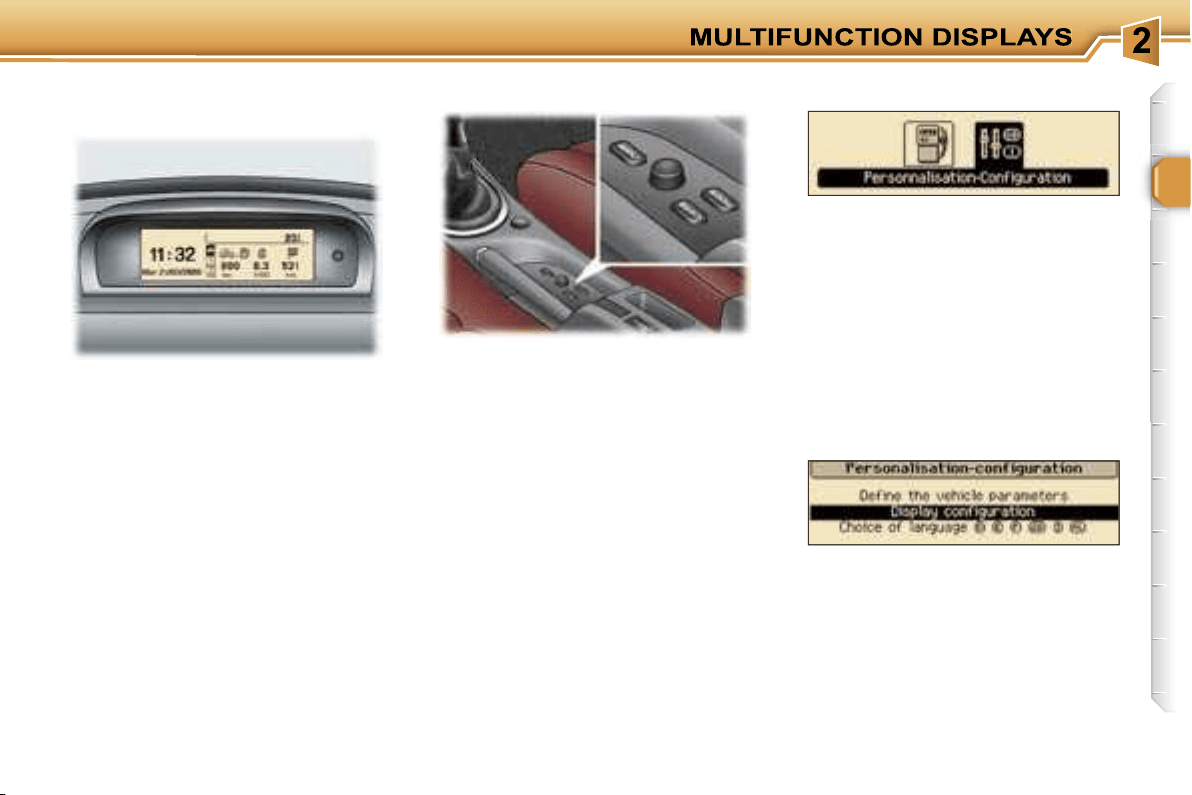
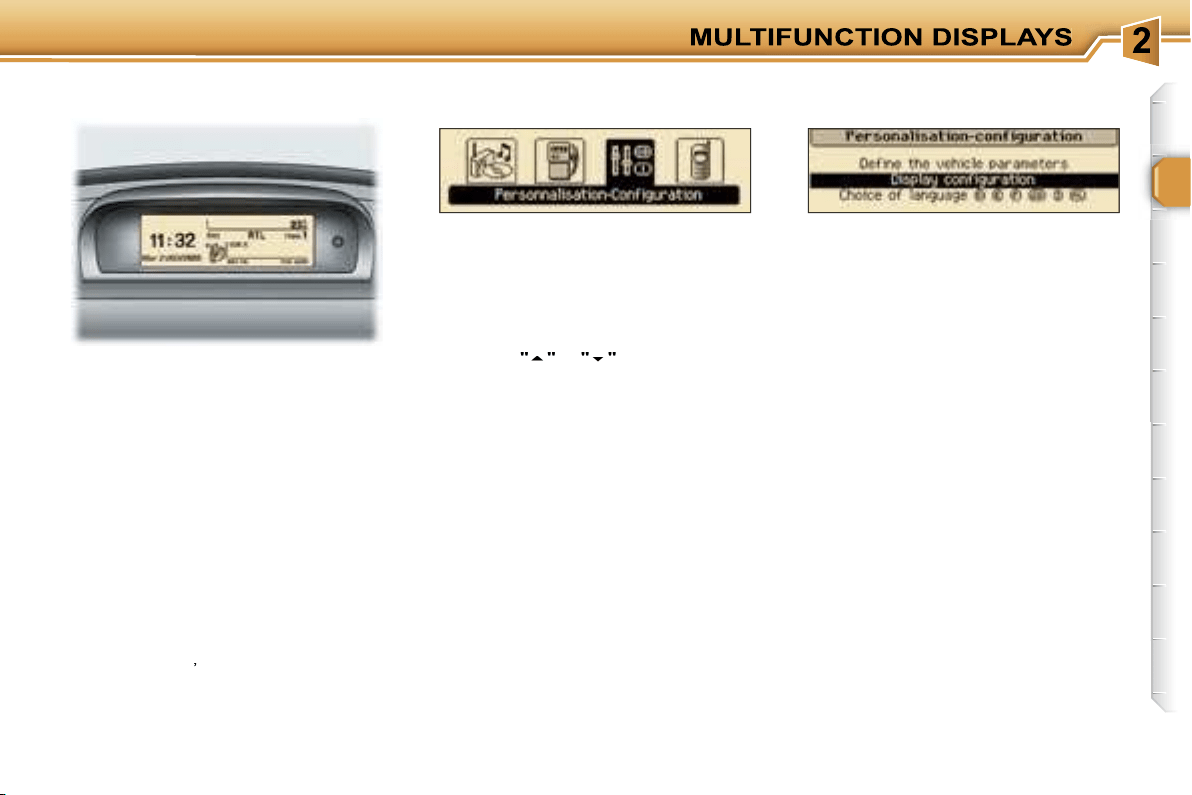
MONOCHROME DISPLAY C
(without RD4 audio equipment)
There are three buttons and a
navigator to enable you to control the
screen:
-
"MENU"
to display the general
menu,
-
"MODE"
to change the permanent
application (trip computer, date, ...),
-
"ESC"
to abandon the operation in
progress,
-
Rotation of the navigator:
move-
ment on the display or changing of
a setting,
-
Press on the navigator:
confirma-
tion of the selection.
Press the
"MENU"
button to access
the general menu:
- trip computer (see corresponding
section),
- personalisation-configuration.
Turn the navigator to select the menu
required, then confirm by pressing
the navigator.
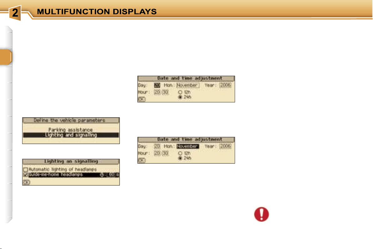
Once this menu has been selected,
you can access the following
functions:
- define the vehicle parameters,
- display configuration,
- selection of the language.
Parameter configuration
General menu
"Personalisation-
Configuration" menu
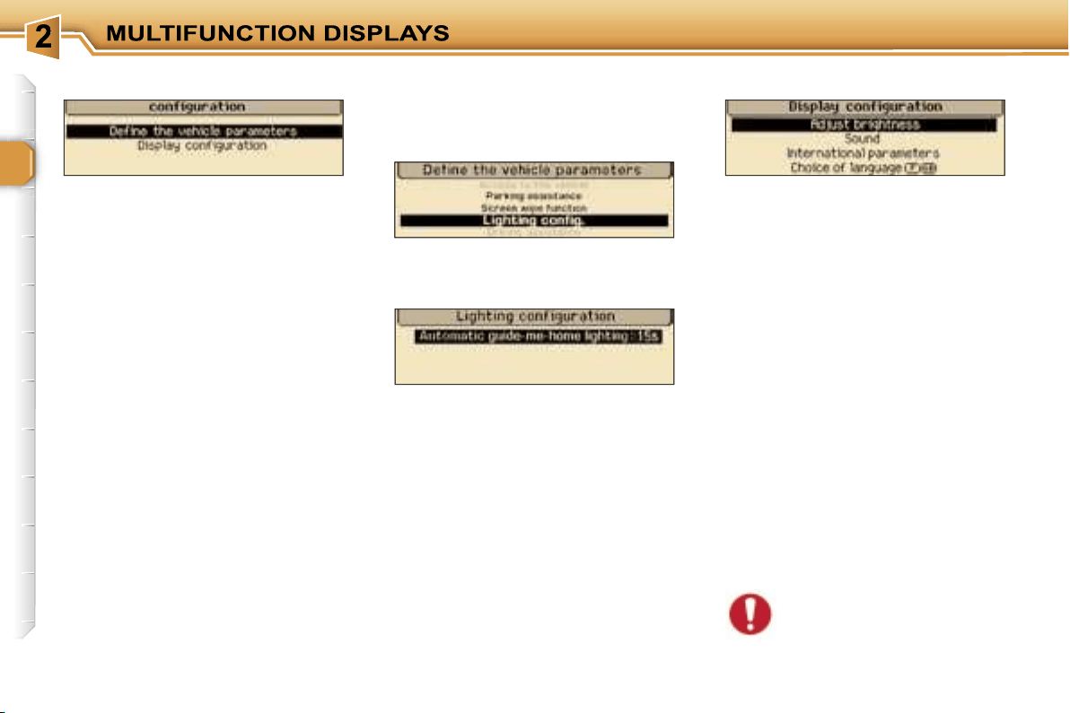
36
Selection of the language
Once this menu has been selected,
you can change the language used
on the display (Deutsch, English,
Espanol, Français, Italiano,
Nederlands, Portugues, Portugues-
Brasil).
Display configuration
Once this menu has been selected,
you can access the following
settings:
- brightness-video setting,
- date and time setting,
- selection of the units.
Example: "Duration of the "follow-
me-home" lighting"
For safety reasons, configu-
ration of the multifunction
displays by the driver must
take place when stationary.
Define the vehicle parameters
Once this menu has been selected,
you can activate or deactivate the
following equipment:
- wiper linked with reverse gear,
- automatic switching on of the
lights,
- "follow-me-home" lighting and
duration,
- parking assistance.
Once you have selected a setting,
press the navigator.
Turn the navigator to change its
value.
Press the navigator to record the
change and move on to the next
setting or press the
"ESC"
button to
cancel.
37
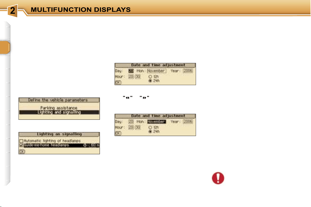
MONOCHROME SCREEN C
Press the
"MENU"
button to gain
access to the general menu:
- audio functions,
- trip computer (see corresponding
section),
- personalisation-configuration,
- telephone (hands-free kit).
Press the
"
"
or
"
"
buttons to select
the menu required, then confirm by
pressing the
"OK"
button.
Presentation
This displays the following information,
via the RD4 audio equipment control
keypad:
- the time,
- the date,
- the outside temperature (this flashes
if there is a risk of ice),
- the audio source displays (radio,
CD, ...),
- the status of the accesses (doors,
boot, ...),
-
the warning messages (e.g.: "Depol-
lution system faulty") or information
messages (e.g.: "Automatic headlamp
lighting activated"), displayed tempo-
rarily, can be cleared by pressing the
"ESC"
button
,
- the trip computer (see corresponding
section).
"Audio functions" menu
With the RD4 audio equipment
switched on, once this menu has
been selected, you can activate
or deactivate the functions linked
with the use of the radio (RDS,
REG, RadioText), the CD or the CD
changer (introscan, random play, CD
repeat).
Once this menu has been selected,
you can gain access to the following
functions:
- define the vehicle parameters,
- display configuration,
- selection of the language.
"Personalisation-
Configuration" menu
General menu
38
Define the vehicle parameters
Once this menu has been selected,
you can activate or deactivate the
folllowing equipment:
- wiper linked with reverse gear,
- automatic switching on of the
lights,
- "follow-me-home lighting" and
duration,
- parking assistance.
Selection of the language
Once this menu has been selected,
you can change the language used
by the display (Deutsch, English,
Espanol, Français, Italiano, Nederlands,
Portugues, Portugues-Brasil).
Display configuration
Once this menu has been selected,
you can gain access to the following
settings:
- brightness-video setting,
- date and time setting,
- selection of the units.
When you have selected a setting,
press the
"OK"
button, then press
the
"
"
or
"
"
buttons to change its
value.
Press the
"OK"
button to record the
change and move on to the next
setting or press the
"ESC"
button to
cancel.
Example: "duration of follow-me-
home lighting"
For safety reasons, configu-
ration of the multifunction
displays by the driver must
take place when stationary.
39
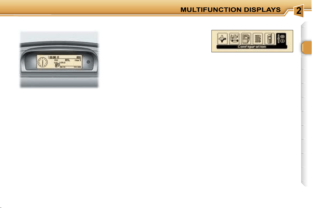
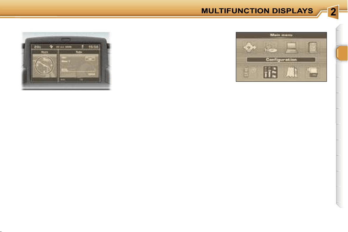
MONOCHROME SCREEN CT
Presentation
This displays the following information,
via the RT3 audio/telephone control
keypad:
- the time,
- the date,
- the outside temperature (if there is
a risk of ice, you are warned by a
message),
- the audio source displays (radio,
CD, ...),
- the telematic system displays (tele-
phone, services, ...),
- the status of the accesses (doors,
boot, ...),
- the warning messages (e.g.: "Fuel
level low") and vehicle function
status messages (e.g.: "Automatic
switching on of the lights activated")
displayed temporarily,
- the trip computer display,
- the satellite navigation system
displays.
In order to enable you to use all of
your system’s functions, you have
two CD-Roms:
- one, "Configuration", contains the
software and the various display
languages and spoken information,
- the other, "Navigation", contains
the satellite navigation system map
data.
Press the
"MENU"
button on the
RT3 audio/telephone to access the
general menu
and select one of the
following applications:
- navigation - guidance,
- audio functions,
- trip computer,
- directory,
- telematics,
- configuration.
For further details regarding these
functions, refer to the corresponding
section.
General menu
40
The
"Display configuration"
menu
provides access to the following
parameters:
• "Brightness setting": setting of the
brightness of the display,
• "Sound": setting of the voice syn-
thesiser (for the male/female voice
parameter: insert the configura-
tion CD-Rom); setting of the voice
commands,
• "International parameters": setting
of the date and time (12 or 24 hour
mode, adjustment of the minutes on
GPS); selection of the units (l/100 - °C
or mpg - °F),
• "Selection of the language": selection
of the language of the display,
information and voice commands
(Français, English, Italiano, Portugues,
Espanol, Deutsch, Nederlands: insert
the configuration CD-rom).
For safety reasons, configu-
ration of the multifunction
displays by the driver must
take place when stationary.
This provides access to successive
confirmation windows.
Example: "duration of follow-me-
home lighting"
Define the vehicle parameters
This enables you to activate or
deactivate certain driving and comfort
functions:
- wiper linked with reverse gear,
- automatic switching on of the lights,
- "follow-me-home" lighting and
duration,
- parking assistance.
"Configuration" menu
Display configuration
41
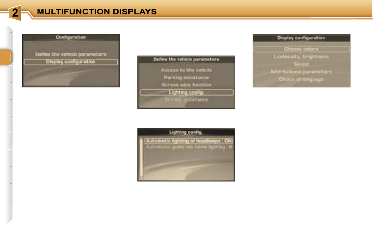
COLOUR SCREEN DT
Presentation
This displays the following information,
via the RT3 audio/telephone control
panel:
- the time,
- the date,
- the outside temperature (if there is
a risk of ice, you are warned by a
message),
- the audio source displays (radio,
CD, ...),
- the telematic system displays (tele-
phone, services, ...),
- the status of the accesses (doors,
boot, ...),
- the warning messages (e.g.: "Fuel
level low") and vehicle function
status messages (e.g.: "Automatic
switching on of the lights activated")
displayed temporarily,
- the trip computer display,
- the satellite navigation system
displays.
In order to enable you to use all of
your system’s functions, you have
two CD-Roms:
- one, "Configuration", contains the
software and the various display
languages and spoken information,
- the other, "Navigation", contains the
satellite navigation system map data.
Press the
"MENU"
button on the
RT3 audio/telephone to access the
general menu
and select one of the
following applications:
- navigation - guidance,
- audio functions,
- trip computer,
- directory,
- telematics,
- configuration,
- map,
- video.
For further details regarding these
functions, refer to the corresponding
section.
General menu
42
The
"Display configuration"
menu
provides access to the following
parameters:
• "Select the colours": selection from
the palette of colours available for
the display,
• "Brightness and intensity": setting
of the brightness and intensity of
the display,
• "Sound": setting of the voice
synthesiser (for the male/female
voice parameter: insert the
configuration CD-Rom); setting of
the voice commands,
• "International parameters": setting
of the date and time (12 or 24 hour
mode, adjustment of the minutes on
GPS); selection of the units (l/100 - °C
or mpg - °F),
• "Selection of the language": selection
of the language of the display,
information and voice commands
(Français, English, Italiano, Portugues,
Espanol, Deutsch, Nederlands: insert
the configuration CD-rom).
This provides access to successive
confirmation windows.
Define the vehicle parameters
This enables you to activate or
deactivate certain driving and comfort
functions:
- wiper linked with reverse gear,
- automatic switching on of the
lights,
- "follow-me-home" lighting and
duration,
- parking assistance.
Example: "Automatic switching on of
the lights"
Display configuration
"Configuration" menu
43
A FEW DEFINITIONS...
Superimposed display
This is a window which appears
temporarily over the current
application to announce a change of
status of another application.
Permanent application
This is the main application currently
in use, displayed as the main screen
window.
Contextual menu
This is a menu, limited to the main
functions of the main application
currently in use, displayed as the
main screen window.
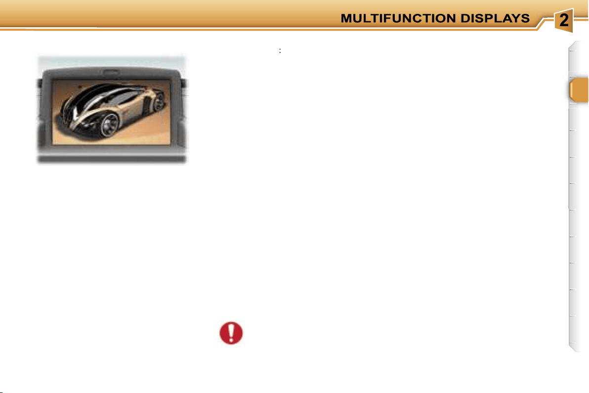
You can connect video equipment
(camcorder, digital camera, DVD
player, ...) to the three audio/video
sockets, located in the glove box.
Videos can only be displayed
when stationary.
Select the
"Video"
menu from the
general menu
:
- "Activate video mode" to activate/
deactivate the video,
- "Video parameters" to set the display
format, the brightness, the contrast
and the colours.
Pressing the
"MODE"
or
"DARK"
button disconnects the display from
the video.
Successive presses on the
"SOURCE"
button permit the selection of an audio
source other than that of the video.
For safety reasons, configu-
ration of the multifunction
displays by the driver must
take place when stationary.
"Video" menu
44
45
VENTILATION
1.
Windscreen de-icing or
demisting vents.
2.
Front window de-icing or
demisting vents.
3.
Side vents.
4.
Centre vents.
5.
Air outlet to front footwells.
6.
Air outlet to rear footwells.
Advice on operation
If, when the vehicle has been
parked in the sun for a long time,
the interior temperature remains
very high, do not hesitate to ven-
tilate the passenger compartment
for a few minutes.
Place the air flow control at a level
sufficient to ensure a good renew-
al of air in the passenger compart-
ment.
When the air flow control is in po-
sition
0
(deactivation of the sys-
tem), temperature related com-
fort is no longer guaranteed but a
slight flow of air, due to the move-
ment of the vehicle, can still be
felt.
For even air distribution, take care
not to obstruct the exterior air in-
take grille at the base of the wind-
screen, the vents, the air outlets
under the front seats and the air
extractor located behind the flaps
in the boot.
Check that the passenger com-
partment filter is in good condi-
tion. Have the filters replaced
regularly. If you drive in a dusty
environment, change them twice
as often.
Switch off the rear screen
and exterior mirrors demist-
ing as soon as you consider
this necessary as reducing
the current consumption reduces the
fuel consumption.
46
The air conditioning only operates
when the engine is running.
2. Temperature adjustment
1. Air conditioning On/Off
Turn the control from blue
(cold) to red (warm) to ad-
just the temperature to your
requirements.
4. Air distribution adjustment
Windscreen and side
windows.
Windscreen, side windows
and footwells.
Footwells
(vents closed).
The air conditioning is de-
signed to operate effectively
in all seasons, with the win-
dows closed. In summer,
it enables the temperature
to be lowered and in winter, above
0 °C, it increases the effectiveness of
the demisting.
Press the switch, the indicator light
comes on.
The air conditioning does not op-
erate while the air flow adjustment
control 3 is in position "0".
Centre and side vents.
3. Air flow adjustment
Turn the control from posi-
tion
1
to position
4
to obtain
an air flow sufficient to en-
sure your comfort.
The air distribution can be adjusted
by placing the control in an interme-
diate position, marked
"
"
.
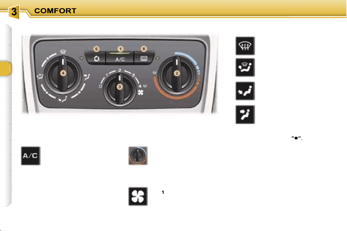
AIR CONDITIONING
47
6. Demisting the rear screen and
the mirrors
Pressing the button once
demists the rear screen
and the exterior mirrors.
This switches off automati-
cally to prevent an exces-
sive consumption of current.
Pressing again reactivates demisting.
It is possible to stop demisting be-
fore it is switched off automatically by
pressing the button again.
In certain cases of particu-
larly arduous use (towing the
maximum load on a steep
gradient in high tempera-
tures), switching off the air condition-
ing permits the recovery of engine
power and therefore an increase in
the towing capacity.
In order for the air conditioning to be
fully effective, the windows must be
closed.
The air conditioning system does not
contain chlorine and does not present
any danger to the ozone layer.
Operate the air conditioning system
for 5 to 10 minutes, once or twice a
month, to keep it in perfect working
order.
The water produced by the air con-
ditioning condensation is discharged
through an opening provided for this
purpose. Therefore, a puddle of wa-
ter may form underneath the vehicle
when stationary.
In order to ensure that the air condi-
tioning system operates correctly, reg-
ular checks are also recommended.
If the system does not produce
cold air, do not use it and contact a
PEUGEOT dealer.
5. Air intake/Air recirculation
Pressing button
5
permits
recirculation of the interior
air. This is indicated by il-
lumination of the indicator
light.
As soon as possible, press button
5
again to permit the intake of outside
air, to prevent deterioration of the air
quality and to avoid misting of the
windows. This is indicated by the
switching off of the indicator light.
The interior air recirculation enables
you to isolate the passenger com-
partment from exterior odours and
smoke.
The outside air intake enables you to
prevent and eliminate misting of the
windscreen and side windows.
Used simultaneously with the air con-
ditioning, air recirculation enables
performance to be improved.
Used in a humid climate, air recir-
culation may result in misting of the
windows.
Rapid demisting of the
windscreen
To quickly de-ice or demist the wind-
screen and side windows:
- place the air distribution control in
the "windscreen and side windows"
position,
- place the temperature
2
and air
flow
3
controls at maximum, as
indicated by the "Windscreen and
side windows" symbol on the con-
trol panel,
- close the centre vents,
- switch air intake button
5
to the
"Outside Air Intake" position (but-
ton
5
indicator light off),
- start the air conditioning by pressing
button
1
.

48
The air conditioning only operates
when the engine is running.
When the engine is cold, to prevent
too great a distribution of cold air, the
air flow will reach its optimum level
gradually.
The driver and his front
passenger can each adjust
the temperature to their re-
quirements.
The value indicated on the
display corresponds to a level of
comfort and not to a temperature in
degrees Celsius or Fahrenheit.
Turn control
2
or
3
to the left or to
the right respectively to decrease or
increase this value.
A setting around the
value 21
provides
optimum comfort. However, depending
on your requirements, a setting between
18 and 24 is normal.
For optimum comfort, you are advised
to avoid a left/right setting difference
of more than 3.
For maximum cooling or heating of the
passenger compartment, it is possible
to go below the value 15 by turning un-
til
"LO"
is displayed or above the value
27 by turning until
"HI"
is displayed.
4. Automatic visibility
programme
The automatic comfort pro-
gramme may not be sufficient
to quickly demist or de-ice the
windscreen and side windows
(humidity, several passengers,
ice, etc.).
In this case, select the automatic vis-
ibility programme.
The system automatically controls
the air conditioning, the air flow and
the air intake and provides optimum
distribution of the ventilation to the
windscreen and side windows.
To switch it off, press button
4
again
or press the
"AUTO"
button, the but-
ton’s indicator light switches off and
"AUTO"
is displayed.
Automatic operation
1. Automatic comfort
programme
Press the
"AUTO"
button.
The
"AUTO"
symbol is dis-
played.
We recommend the use of
this mode: it permits auto-
matic and optimised adjustment of
all of the functions, passenger com-
partment temperature, air flow, air
distribution and air recirculation, in
accordance with the comfort value
that you have chosen. This system is
designed to operate effectively in all
seasons, with the windows closed.
2. Driver’s side adjustment
3. Passenger side adjustment
On entering the vehicle, if
the interior temperature is
much colder or warmer than
the comfort value, there is no
need to change the value displayed
in order to obtain the comfort re-
quired. The system corrects the dif-
ference in temperature automatically
and as quickly as possible.
DUAL ZONE AUTOMATIC AIR CONDITIONING
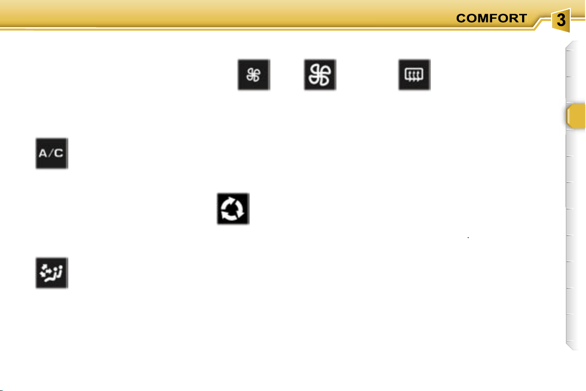
49
Manual operation
If you wish, you can make a different
choice from that offered by the sys-
tem by changing a setting. The other
functions will still be controlled auto-
matically. Pressing the
"AUTO"
button
returns the system to completely auto-
matic operation.
Press this button to stop air
cooling.
Avoid prolonged use of this
mode (risk of condensation,
odour, humidity).
Press this button again as soon as
possible to return to automatic op-
eration of the air conditioning. The
symbol
"A/C"
is displayed.
6. Air distribution adjustment
Pressing this button sev-
eral times in succession
enables the air flow to be
directed in turn towards:
- the windscreen and side windows
(de-icing or demisting),
- the windscreen, the side windows
and the footwells,
- the footwells,
- the centre vents, the side vents and
the footwells,
- the centre and side vents.
7. Air flow adjustment
Press the
"small fan"
or
"large fan"
button respectively to decrease or in-
crease the flow of air.
The air flow symbol, the fan, fills pro-
gressively in relation to the value re-
quired.
8. Air intake/Air
recirculation
9. Demisting the rear screen
and the mirrors
10. Switching the system off
Press the
"small fan"
button of the
air flow
7
until the fan symbol disap-
pears.
This action switches off all of the func-
tions of the air conditioning system,
with the exception of the demisting of
the rear screen
9
.
Temperature related comfort is no
longer guaranteed but a slight flow of
air, due to the movement of the vehi-
cle, can still be felt.
Pressing the
"large fan"
button of
the air flow
7
again or the
AUTO
but-
ton reactivates the system with the
values set before it was switched off.
Press this button for recir-
culation of the interior air.
The air recirculation symbol
8
is displayed.
Air recirculation enables the
passenger compartment to be isolat-
ed from exterior odours and smoke.
Avoid prolonged recirculation of interior
air (risk of condensation and deteriora-
tion of the air quality).
As soon as possible, press this button
again to permit the intake of outside
air and prevent condensation.
5. Air conditioning
On/Off
Press this button to demist
the rear screen and the ex-
terior mirrors. The button
9
indicator light comes on.
Demisting switches off au-
tomatically to prevent an
excessive consumption of current.
It is possible to stop operation of the
demisting before it is switched off
automatically by pressing the button
again.

50
Electric exterior mirrors
Adjustment
Slide switch
A
to the right or to the
left to select the corresponding
mirror.
Move knob
B
in all four directions
to adjust.
Return switch
A
to the centre
position.
Folding
- from inside:
with the ignition on, pull switch
A
rearwards.
- from outside:
lock the vehicle using the remote
control or the key.
Unfolding
- from inside:
with the ignition on, pull switch
A
rearwards.
- from outside:
unlock the vehicle using the
remote control or the key.
The folding and unfolding of
the exterior mirrors can be
deactivated by a PEUGEOT
dealer.
In certain cases of particu-
larly arduous use (towing the
maximum load on a steep
gradient in high tempera-
tures), switching off the air condition-
ing permits the recovery of engine
power and therefore an increase in
the towing capacity.
In order for the air conditioning to be
fully effective, the windows must be
closed.
The air conditioning system does not
contain chlorine and does not present
any danger to the ozone layer.
Operate the air conditioning for 5 to
10 minutes, once or twice a month, to
keep it in good working order.
The water produced by the air con-
ditioning condensation is discharged
through an opening provided for this
purpose. Therefore, a puddle of wa-
ter may form underneath the vehicle
when stationary.
In order to ensure that the air condi-
tioning system operates correctly, reg-
ular checks are also recommended.
If the system does not produce cold air,
do not use it and contact a PEUGEOT
dealer.
Note:
if the mirrors are folded using
switch
A
, they will not unfold when
the vehicle is unlocked using the
remote control or the key. Switch
A
must be pulled again.
MIRRORS
The end of the driver’s mirror is
aspheric (outer area indicat-
ed by a dotted line) in order
to reduce the "blind spot".
Objects seen in the driver and
passenger mirrors are in reality
closer than they appear.
Therefore, this must be taken into ac-
count in order to correctly judge the
proximity of vehicles approaching
from the rear.
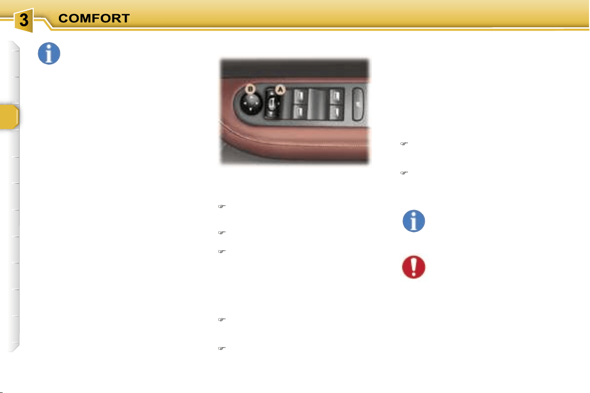

51
This automatically and gradually
changes between the day and night
positions. To prevent dazzling, the
glass of the mirror darkens auto-
matically depending on the intensity
of the light from behind. It clears as
the light (headlamps of following ve-
hicles, sunlight) decreases, ensuring
maximum visibility.
Manual interior mirror
The interior mirror has two positions:
- day (normal),
- night (anti-dazzle).
To change from one to the other,
push or pull the lever on the lower
edge of the mirror.
Operation
Switch on the ignition and press
switch
1
:
- Indicator light
2
lit (switch pressed):
automatic operation.
- Indicator light
2
off: automatic
system off. The mirror remains at
its most clear.
Special feature
To ensure maximum visibility during
manoeuvres, the mirror clears auto-
matically when reverse gear is en-
gaged.
When the vehicle is stationary, un-
lock the steering wheel by pulling
handle
A
.
Adjust the height and depth of the
steering wheel.
Lock it by pushing handle
A
down
fully.
STEERING WHEEL HEIGHT
AND DEPTH ADJUSTMENT
Automatic day/night interior
mirror
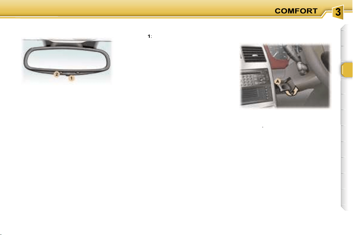
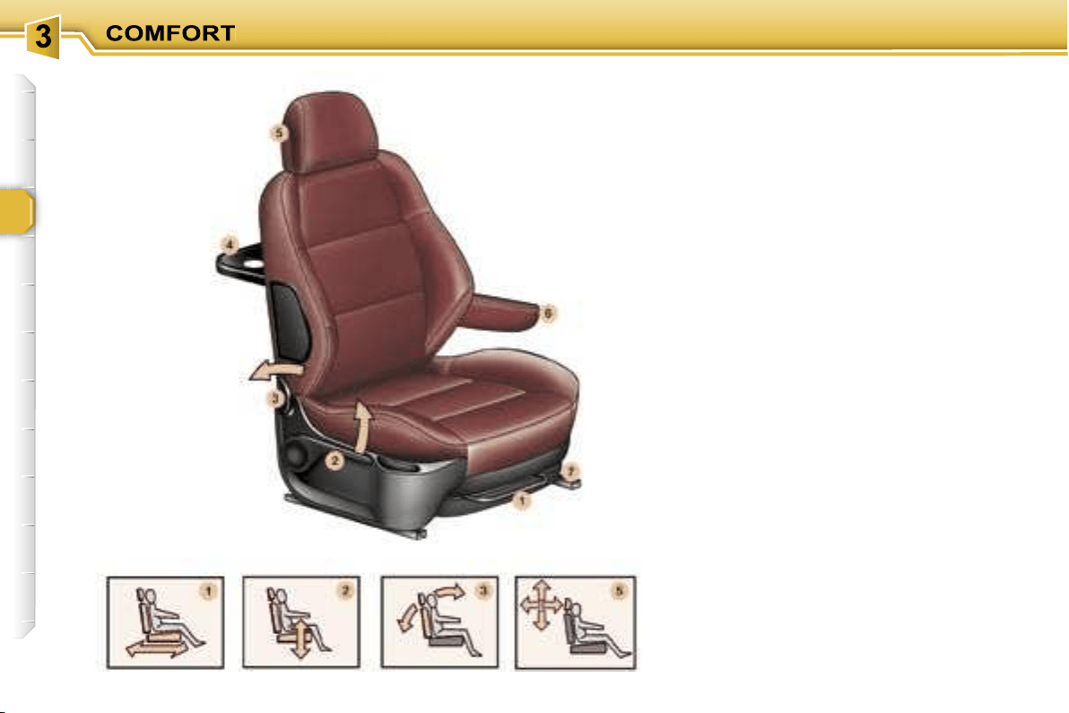
52
FRONT SEATS
1. Forwards
/
backwards
adjustment
Lift the control and slide the seat for-
wards or backwards.
2. Driver’s or passenger’s seat
height adjustment
Pull the handle upwards or push it
downwards as many times as neces-
sary to obtain the required position.
3.
Seat
back angle adjustment
Push the handle towards the rear.
4. "Aircraft" style table
There is an "aircraft" style table,
fitted with a can holder, at the rear of
each front seat.
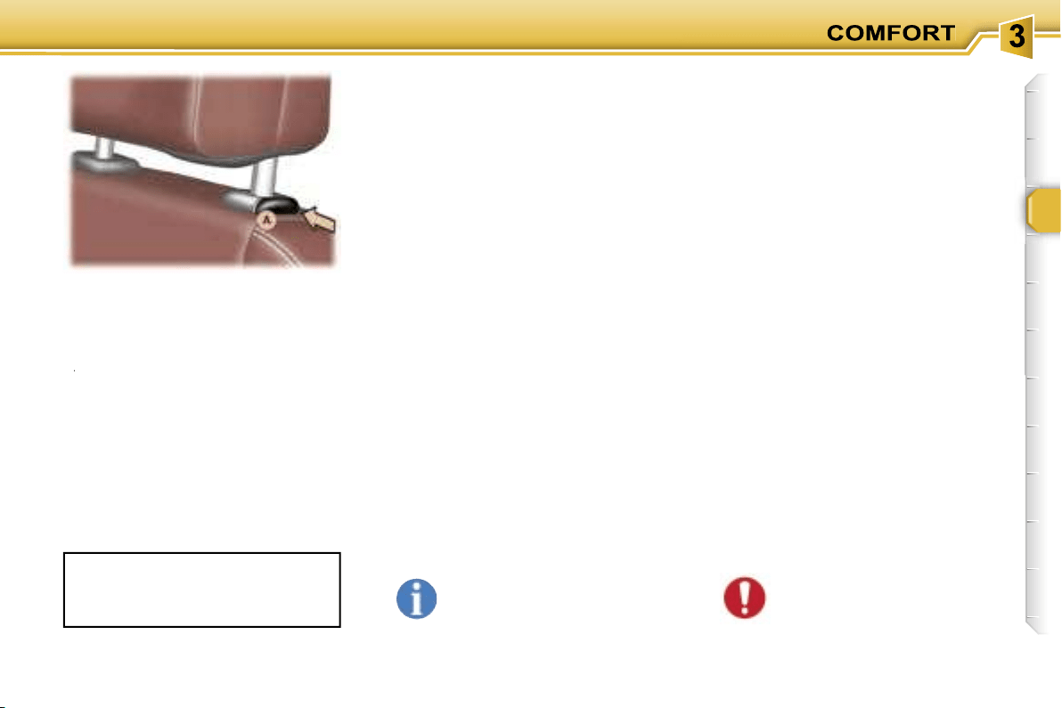
53
5. Head restraint height
and angle adjustment
To raise the head restraint, pull it up-
wards.
To remove the head restraint, press the lug
A
and pull the head restraint upwards.
A
A
To put the head restraint back in po-
sition, locate the stems of the head
restraint in the holes, taking care to
keep them in line with the seat back.
To lower the head restraint, press the
lug
A
and the head restraint at the
same time.
The head restraint frame has a catch
which prevents it from lowering; this
safety device provides protection in
the event of an impact.
Never drive with the head
restraints removed; they
should be in place and cor-
rectly adjusted.
6. Armrests
These can be folded down and are
removable.
To remove them, press the button lo-
cated between the armrest and the
side of the seat and pull it.
7. Storage drawers
There is a storage drawer under each
front seat*.
- To open it, lift it and pull.
- To take it out, open it to its full extent,
press the ends of the slides and lift
it, then remove it completely.
- To put it back in place, at the end of
its travel, press the top of the draw-
er to secure it.
Under the front passenger seat, the
layout of the floor allows for storage
of a first aid kit and a warning triangle
(small version).
The adjustment is correct when the
upper edge of the head restraint is
level with the top of the head.
To tilt the head restraint, tilt the lower
part forwards or backwards.
Do not place heavy objects
in the drawers.
REAR HEAD RESTRAINTS
These have a high position for when
they are in use and a low position for
when they are stored.
The head restraints are
also remov-
able.
To remove them, pull upwards as far
as the stop, then press the lug (side
seat) or the two lugs (centre seat).
* According to version.

54
Exit from the 3rd row or folding
from the boot
Place the head restraint in the low
position.
Fold the seat back onto the cushion
using the strap
B
.
Note:
you can lock the seat back
in this position (for removal) by press-
ing down on it.
Pull the strap
C
upwards to release
the rear feet.
Place the seat in the folded position.
Forwards-backwards adjustment*
Lift the bar
A
and slide the seat
forwards or backwards.
* Except additional seat.
Seat back angle adjustment
Pull the strap
B
, at the front of the
seat on the right or on the left, then
adjust to the required angle.
Release the strap to lock.
To adjust the angle of the seat back
from the 3rd row or the boot, pull the
strap
B
at the rear of the seat.
Note:
the additional seat can be
angled and folded by means of the
strap
B
at the rear of the seat on the
right or on the left.
Access to the 3rd row
Place the head restraint in the low
position.
If necessary, push the seat back
using bar
A
.
Fold the seat back onto the cushion
using the strap
B
.
Note:
you can lock the seat back
in this position (e.g. for removal) by
pressing down on it.
Pull the strap
C
upwards to release
the rear feet.
Place the seat in the "folded" position.
Folding a side seat
REAR SEATS
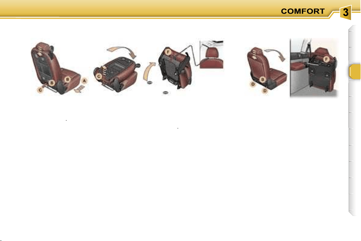
55
Place the head restraint in the low
position.
Fold the seat back onto the cushion
using the strap
B
.
You now have a small table with four
can holders, two pen holders and a
document holder.
Folding the centre seat
Place the head restraint in the low
position.
Fold the seat back onto the cushion
using the strap
B
.
Note:
you can lock the seat back
in this position (for removal) by press-
ing down on it.
Pull the strap
C
upwards to release
the rear feet.
Place the seat in the folded position.
While driving, attach the retain-
ing strap (contained in the storage
pocket of one of the front seats) on
one side to the carrying handle F
and on the other side, to one of the
stems of a front head restraint.
Place the head restraint in the low
position.
Pull the strap
B
(at the rear of the
seat to the right or to the left) back-
wards then press on the seat back to
release it, while continuing to pull the
strap.
Fold the seat back onto the seat
cushion.
Note:
you can lock the seat back
in this position (for removal) by press-
ing down on it.
Push the two levers
D
upwards to un-
lock the rear feet.
Place the seat in the folded position.
While driving, attach the retain-
ing strap (contained in the storage
pocket of the additional seat) on
one side to the carrying handle F
and on the other side, to the rear
armrest grab handle.
Centre seat table
position
Folding an additional
seat
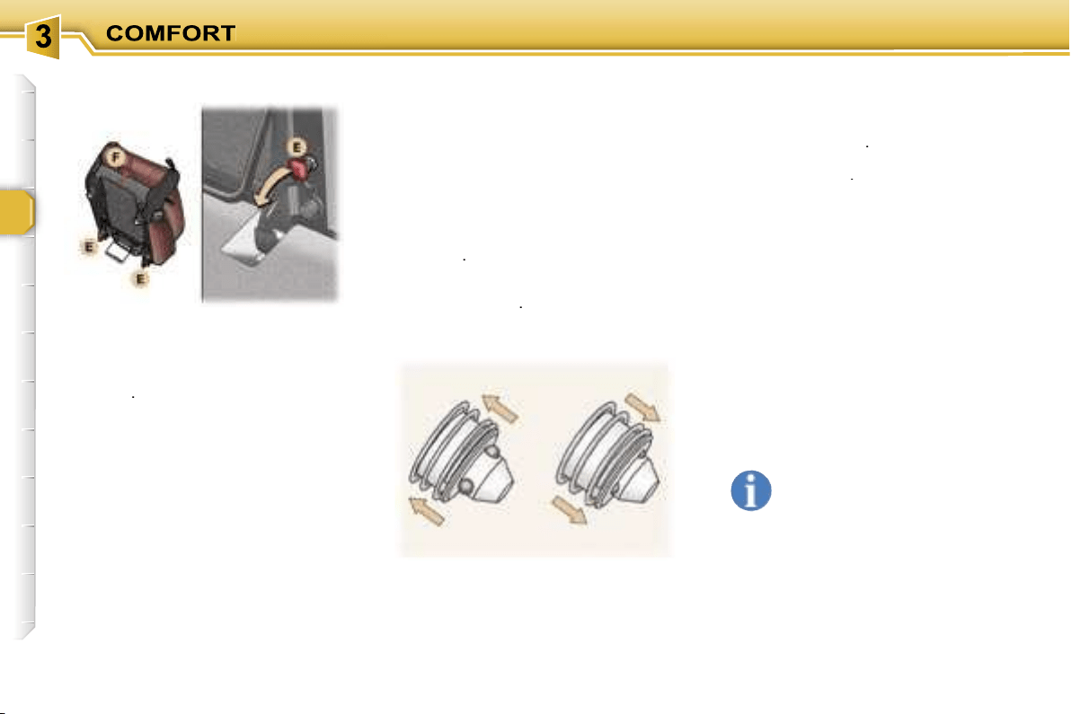
56
Fold the corresponding seat.
Tilt the two red levers
E
under the
seat to release the front feet.
Lift it and carry it using the carrying
handle
F
.
In the 3rd row, position the fixing point
closers to obtain a flat boot floor.
Refitting a seat
In the 3rd row, first remove the floor
fixing point closers using a thin
screwdriver.
Before positioning the 3rd row seats,
move those of the 2nd row forward if
necessary.
Check that nothing is obstructing the
floor fixing points thus preventing
correct locking of the seat feet.
Carry the seat using the carrying
handle
F
.
Position the front feet in the securing
points and lock them by means of the
two red levers
E
.
Locked
Pull the strap
C
upwards to check
that the rear feet are free.
Tilt the folded seat backwards.
The rear feet lock automatically.
Check that the seat is locked
correctly.
Lift the seat back, first releasing it by
pulling the strap
B
.
To lock the additional seats, press
the two levers
D
.
Only lock the seat back on
the cushion occasionally, to
avoid undue wear of the seat
covers.
Avoid placing luggage on folded
seats.
Never use the adjusting straps to re-
move, refit or carry a seat, use the
carrying handle provided for this pur-
pose.
Free
Removing a seat
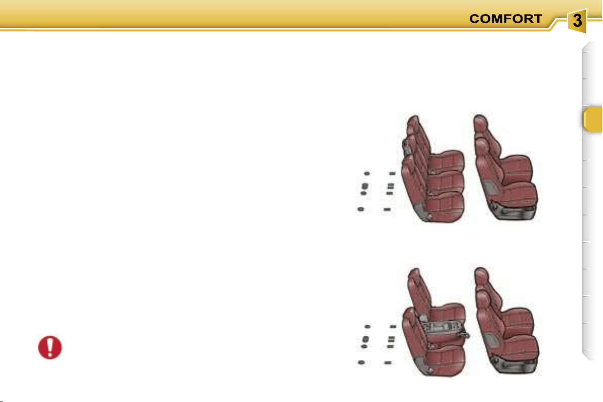
57
SEAT MODULARITY AND DIFFERENT CONFIGURATIONS
The design of your vehicle and of its seats offers multiple
seat configurations.
There are
side seats
which can be installed in the 2nd or
3rd row, on the right or on the left.
Once the centre seat has been removed from the 2nd row,
you can recentre the side seats for more comfort.
There is also a
centre seat
, fitted in the central position of
the 2nd row, which can also be installed in the left position
in the 3rd row.
In this case, you must use the 3rd row rear left seat belt
without passing it through the strap guide.
You can add up to two
additional seats
in the 3rd row, on
the right or on the left.
The various operations resulting in modifica-
tion of the existing configuration must be carried
out when the vehicle is stationary (see "Seats"
section).
Examples of varied arrangements combining comfort
and practicality:
5 seats
4 seats with table position
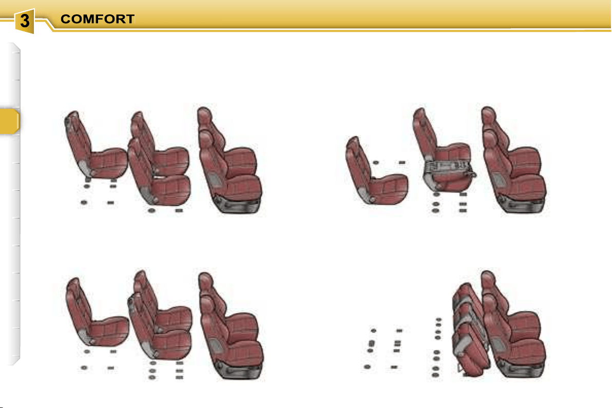
58
5 seats with centre seat in the 3rd row
Transportation of long objects
4 seats with side seat in the 3rd row
Loading of a large volume
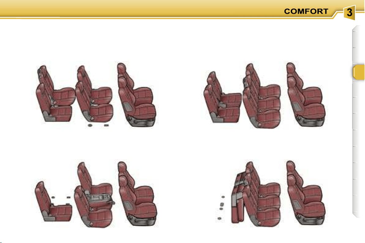
59
6 seats with an additional seat and the centre seat in
the 3rd row
5 seats with table position and one additional seat
7 seats with two additional seats
5 seats with two folded additional seats
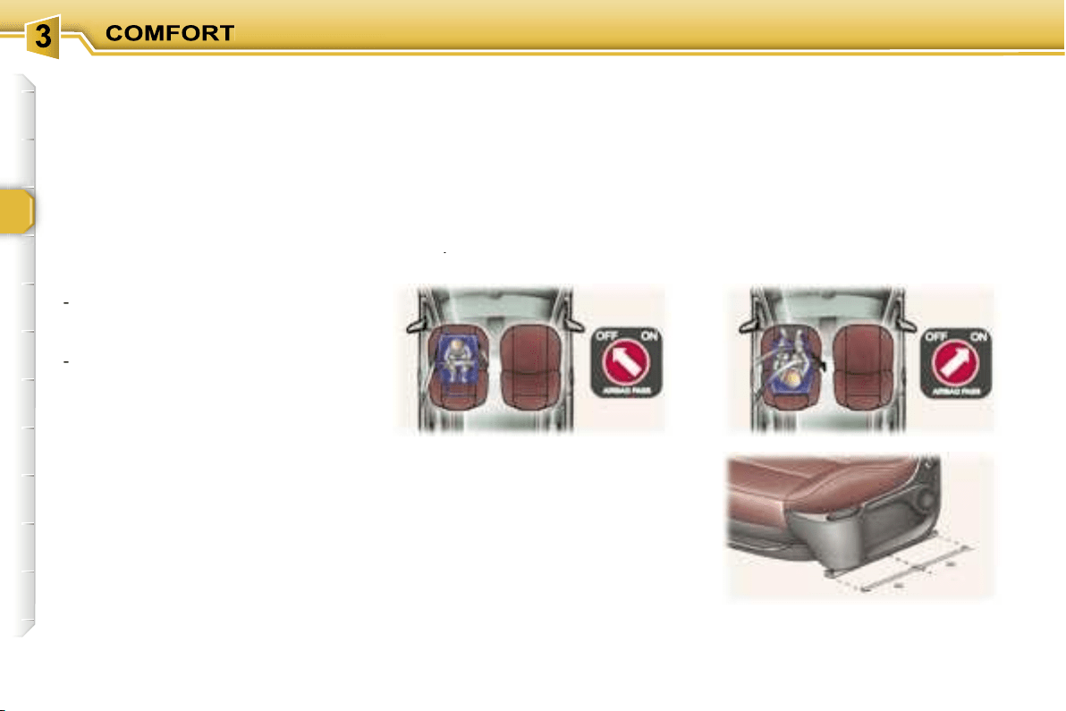
60
"Forwards-facing"
When a "forwards-facing" child seat
is installed on the
front passenger
seat
, adjust the vehicle’s seat to the
intermediate longitudinal position
with the seat back upright and leave
the passenger air bag armed**.
INSTALLING A CHILD SEAT
USING A THREE POINT SEAT
BELT
"Rearwards-facing"
When a "rearwards-facing" child seat
is installed on the
front passenger
seat
, it is essential that the passenger
air bag** is disarmed. Otherwise,
the
child would risk being seriously in-
jured or killed if the air bag were to
inflate
.
GENERAL POINTS RELATING
TO CHILD SEATS
Although one of PEUGEOT’s main
criteria when designing your vehicle,
the safety of your children also de-
pends on you.
For maximum safety, please follow
these precautions:
- since 1992, and in accordance with
Directive 2000/3,
all children un-
der the age of 12 must travel in
approved child seats* suited to
their weight
, on seats fitted with a
seat belt or ISOFIX mountings**.
-
statistically, the safest seats in
your vehicle for the transpor-
tation of children are the rear
seats,
-
a child weighing less than 9 kg
must travel in the "rearwards-
facing" position both in the front
and in the rear.
PEUGEOT recommends
that children
should travel in the
rear seats
of your
vehicle:
-
"rearwards-facing"
up to the age
of 2,
-
"forwards-facing"
over the age of 2.
* According to current legislation in
the country.
** According to model.
Intermediate longitudinal
position

61
** According to version.
Passenger air bag OFF**
CHILD SEATS RECOMMENDED BY PEUGEOT
PEUGEOT offers a complete range of recommended child seats which are se-
cured using a
three point seat belt
:
Group 0: from birth to 10 kg
Group 0+: from birth to 13 kg
L1
"BRITAX
Babysure"
(E11 0344117)
Installed in
the rear-facing
position.
L2
"ROMER
Baby-Safe"
(E1 03301146)
Installed in
the rear-facing
position.
L3
"MAXI COSI
Cabrio"
(E4 03443301/
E4 04443517)
Installed in
the rear-facing
position.
Groups 1, 2 and 3: from 9 to 36 kg
L4
"KIDDY Life"
(E1 03301135)
For the safety of
young children
(from 9 to 18 kg),
PEUGEOT
recommends use
of the restraining
cushion.
Groups 2 and 3: from 15 to 36 kg
L5
"RECARO Start"
(E1 03301108)
L6
"KLIPPAN Optima"
(E17 030007) From
the age of 6 years
(approximately
22 kg), the booster
is used on its own.
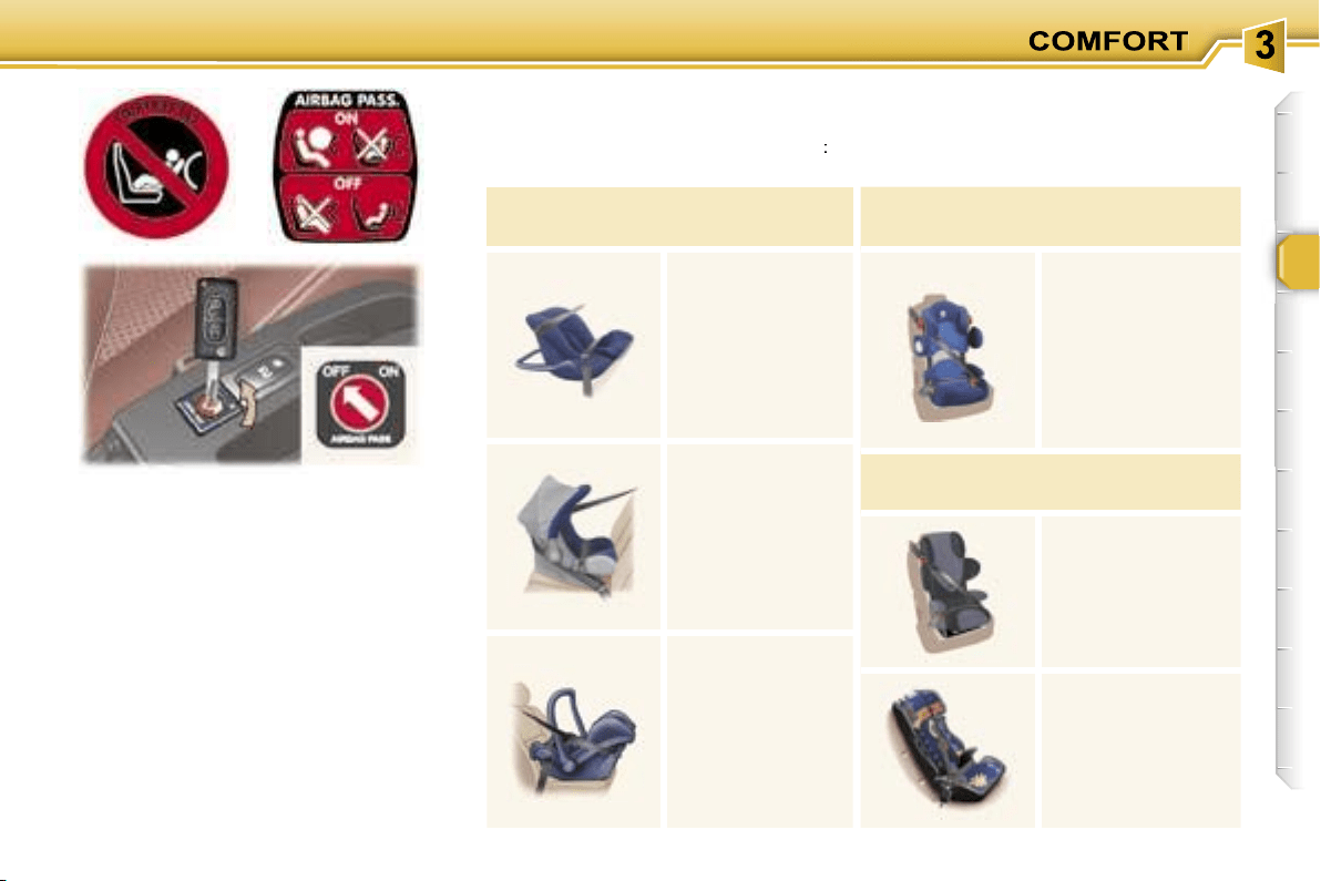
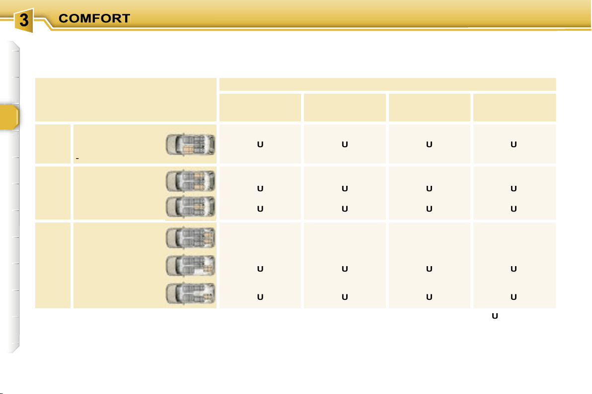
62
Seat
Weight of the child/
indicative age
Below 13 kg
(groups 0 (b) and 0+)
Up to 1 year approx
9 to 18 kg
(group 1)
1 to 3 years approx
15 to 25 kg
(group 2)
3 to 6 years approx
22 to 36 kg
(group 3)
6 to 10 years approx
1st
row
Front passenger
seat (c)
- fixed
-
height adjustable (R)
U
U (R)
U
U (R)
U
U (R)
U
U (R)
2nd
row
Side
Seat off centre
and recentred
Centre
Centre seat
U
U
U
U
U
U
U
U
3rd
row
Side
Additional seat
L1, L2
L4
L4, L5, L6
L4, L5, L6
Side
2nd row
side seat
U
U
U
U
Side
2nd row
centre seat
U
U
U
U
LOCATION OF CHILD SEATS SECURED USING THE SEAT BELT
In accordance with the European regulation (Directive 2000/3), this table indicates the options for the installation of child seats
secured using the seat belt and universally approved (a) depending on the weight of the child and the seat in the vehicle.
(a) Universal child seat: child seat
which can be installed in all
vehicles using the seat belt.
(b) Group 0: from birth to 10 kg.
(c) Consult the current legislation
in your country before installing
your child on this seat.
U:
seat suitable for the installation of
a child seat secured using the seat
belt and universally approved, "rear
facing" and/or "forwards facing".
U (R):
identical to
U
, the vehicle
seat must be adjusted to the highest
position.
L-:
only the child seats indicated can
be installed on the seat concerned
(according to country).
63
ADVICE ON CHILD
SEATS
Children under the age of 10 must not
travel in the "forward facing" position
on the front passenger seat, unless
the rear seats are already occupied
by other children, cannot be used or
are absent.
Disarm the passenger air bag* when
a "rear facing" child seat is installed
on the front seat. Otherwise, the child
would risk being seriously injured or
killed if the air bag were to inflate.
* According to version.
Installing a booster seat
The chest part of the seat belt must
be positioned on the child’s shoulder
without touching the neck.
Ensure that the lap part of the seat
belt passes correctly over the child’s
thighs.
PEUGEOT recommends the use of
a booster seat which has a back,
fitted with a seat belt guide at shoul-
der level.
As a safety precaution, do not leave:
- one or more children alone and
unsupervised in a vehicle,
- a child or an animal in a vehicle
which is exposed to the sun, with
the windows closed,
- the keys within reach of children in-
side the vehicle.
To prevent accidental opening of the
doors, use the "Child lock"*.
Take care not to open the rear
windows by more than one third*.
To protect young children from the
rays of the sun, fit side blinds on the
rear windows.
The incorrect installation of a child
seat in a vehicle compromises the
child’s protection in the event of an
accident.
Remember to fasten the seat belts
or the child seat harnesses
keeping
the slack
in relation to the child’s
body
to a minimum
, even for short
journeys.
For optimum installation of the "for-
ward facing" child seat, ensure that
the back of the child seat is in contact
with the back of the vehicle’s seat
and that the head restraint does not
cause any discomfort.
If the head restraint has to be re-
moved, ensure that it is stored or at-
tached securely to prevent it from be-
ing thrown around the vehicle in the
event of sharp braking.
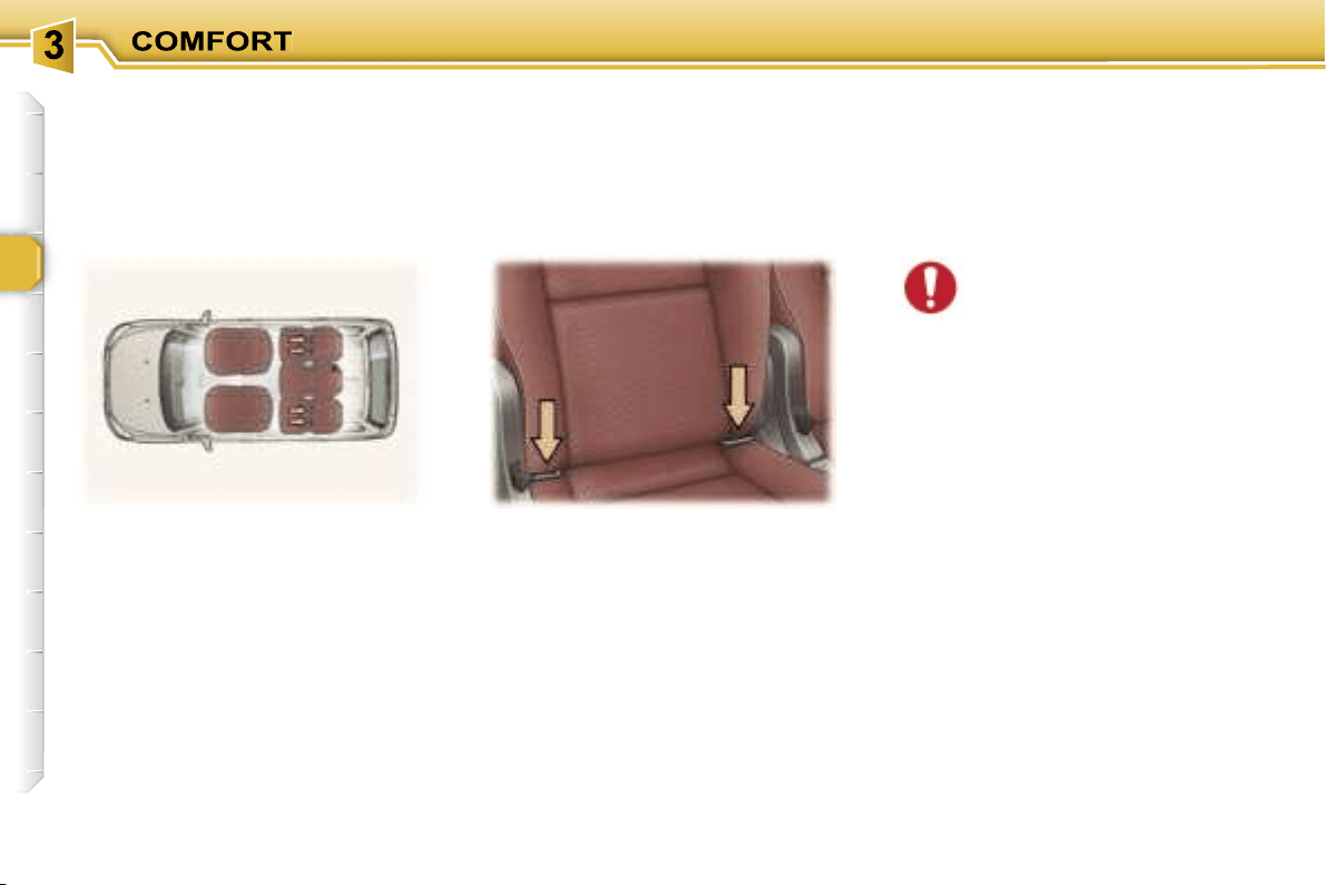
64
These are two rings located between
the seat back and the seat cushion.
The
ISOFIX child seats
are fitted
with two locks which are secured
easily on these rings.
"ISOFIX" MOUNTINGS
These seats* are fitted with ISOFIX
mountings.
This ISOFIX mounting system guar-
antees reliable, safe and fast fitting of
the child seat in your vehicle.
* According to version.
The additional seats are not
fitted with ISOFIX mountings.
If you wish to install an ISO-
FIX child seat in the 3rd row,
one of the 2nd row side seats must
be placed in the 3rd row.
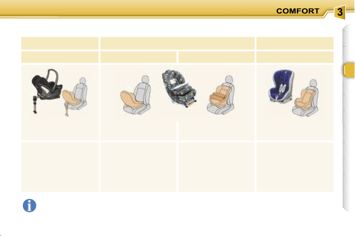
65
ISOFIX CHILD SEATS RECOMMENDED BY PEUGEOT
AND APPROVED FOR YOUR VEHICLE
These child seats can also be used on seats which are not fitted with ISOFIX mountings. In this case, it is essential
that they are secured to the vehicle’s seat by means of the three point seat belt.
Follow the instructions for fitting the child seat indicated in the seat manufacturer’s installation guide.
MAXI COSI CabrioFix
ISOFIX KIDDY
ISOFIX RÖMER Duo
Group 0+:
from birth to 13 kg
Group 0+:
from birth to 13 kg
Group 1: from 9 to 18 kg
Group 1: from 9 to 18 kg
Installed in the rear facing
position in the 2nd row only.
Installed in the rear
facing position in the 2nd
and 3rd rows.
Installed in the forwards
facing position, in the
2nd row only.
Installed in the forwards
facing position only.
The ISOFIX base is fitted with
a height adjustable strut.
This strut must be in contact
with the floor of the vehicle.
In the 2nd row, the side seats
must be recentred. The body
of the child seat must be in
contact with the back of the
corresponding front seat.
In the 3rd row, the body of the
child seat must be in contact
with the back of a 2nd row
side seat.
It is essential that the vehi-
cle’s front seat is adjusted to
the intermediate longitudinal
position.
Secured without the top strap.
Three child seat body angles:
sitting, reclining and lying po-
sitions.
Adjust the vehicle’s front seat
so that the child’s feet do not
touch the seat back.
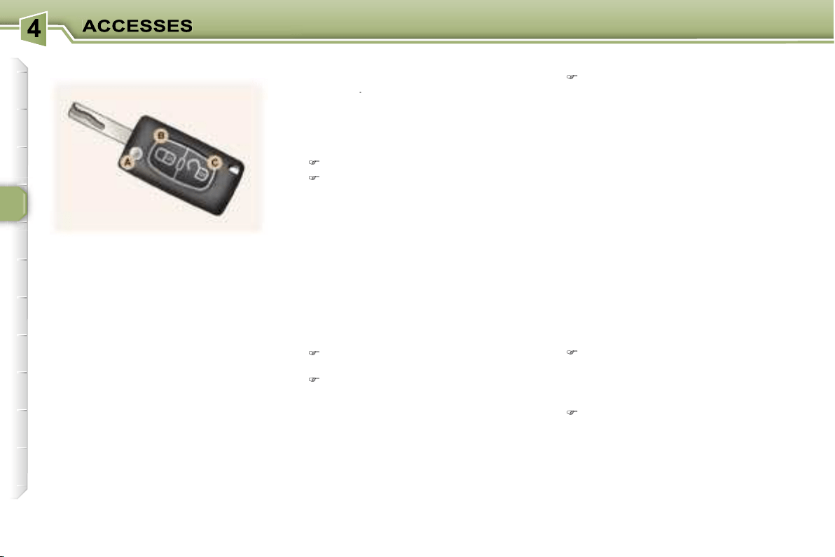
66
The remote control permits locking,
deadlocking, unlocking and locating
of the vehicle, as well as folding and
unfolding of the exterior mirrors.
The key allows you to switch on the
ignition and mechanically and inde-
pendently operate the lock on the
glove box, the fuel filler cap, the pas-
senger air bag disarming switch and
the child lock.
From the driver’s door, the key al-
lows you to electrically control the
locking, deadlocking and unlocking
of the doors and tailgate, as well as
the folding and unfolding of the exte-
rior mirrors.
If one of the doors or the boot is open,
the central locking does not work.
Using the key
Turn the key in the lock on the
driver’s door to lock the vehicle.
Turn the key and hold it in this posi-
tion for more than two seconds to
activate the automatic closing of
the windows in addition to locking.
Each action is confirmed by fixed
lighting of the direction indicators for
approximately two seconds.
At the same time, the exterior mirrors
fold back.
Unfolding/Folding the key
To unfold or fold the key, first press
button
A
.
Locking
Using the remote control
Press
button
B
to lock the vehicle.
Press button B for more than
2 seconds
to activate the auto-
matic closing of the windows in
addition to locking.
Each action is confirmed by fixed
lighting of the direction indicators for
approximately two seconds.
At the same time, the exterior mirrors
fold back.
Deadlocking
This renders the
internal
and exter-
nal door locking controls inoperative.
It also disarms the internal central
locking button.
Unlocking
Press button
C
to unlock the vehi-
cle.
This is confirmed by rapid flashing of
the direction indicators.
At the same time, the exterior mirrors
unfold.
Using the remote control
One press
on button
B
locks the
vehicle or
one press on button
B for more than 2 seconds
acti-
vates the automatic closing of the
windows in addition to locking.
A second press
within five seconds
deadlocks the vehicle.
Each action is confirmed by fixed
lighting of the direction indicators for
approximately two seconds.
THE REMOTE CONTROL KEY

67
ELECTRONIC ENGINE
IMMOBILISER
This locks the engine control sys-
tem a few moments after the ignition
has been switched off and therefore
prevents starting of the vehicle by
anyone who does not have the key.
The ignition key has an electronic
chip which has a special code. When
the ignition is switched on, the code is
recognised and starting is possible.
If the system does not function cor-
rectly,
the service warning light comes
on, accompanied by an audible signal
and a message on the multifunction
display.
In this case, your vehicle will not start.
Contact a PEUGEOT dealer as soon
as possible.
Battery ref.: CR1620/3 volts.
The information "battery flat" is given
by displaying of the service warning
light, accompanied by an audible
signal and a message on the multi-
function display.
To replace the battery, unclip the cas-
ing using a coin at the notch.
If the remote control does not work
after the battery has been changed,
re-programme the remote control.
Key in ignition
A buzzer sounds on opening the
driver’s door, if the key has been left
in the ignition.
Reprogramming the remote
control
Following disconnection of the vehi-
cle’s battery, replacement of the re-
mote control battery or in the event
of a remote control malfunction, the
remote control must be reinitialised.
Switch off the ignition.
Switch the ignition on again.
Press the remote control locking but-
ton immediately for a few seconds.
Switch off the ignition and remove
the remote control key from the ig-
nition lock.
The remote control is now working
again.
Locating your vehicle
Using the key
Turn the key in the lock on the
driver’s door to lock the vehicle
and hold it in this position for more
than two seconds to activate the
automatic closing of the windows
in addition to locking.
Turn the key again within five sec-
onds to deadlock the vehicle.
Each action is confirmed by fixed
lighting of the direction indicators for
approximately two seconds.
When the vehicle is locked,
if unlocking is activated inad-
vertently without a door being
opened within 30 seconds,
the vehicle will lock automatically.
The folding and unfolding of the ex-
terior mirrors can be deactivated by
a PEUGEOT dealer.
To locate your vehicle, if
you have locked it, in a
car park:
press button
B
, the courtesy lights
come on and the direction indica-
tors flash for a few seconds.
Changing the remote control
battery

68
Make a careful note of the
number on each key. The key
number is coded on the label
attached to the key.
If the keys are lost, your PEUGEOT
dealer can rapidly supply you with
new keys.
The high frequency remote con-
trol is a sensitive system; do not
operate it while it is in your pocket
as there is a possibility that it may
unlock your vehicle, without you
being aware of it.
The remote control does not oper-
ate when the key is in the ignition,
even when the ignition is switched
off, except for reprogramming.
Do not operate the deadlocking
function if there is anyone inside
the vehicle.
Driving with the doors locked may
make access to the passenger com-
partment by the emergency services
more difficult in an emergency.
As a safety precaution (with chil-
dren on board), remove the ignition
key when you leave the vehicle,
even for a short time.
Do not repeatedly press the but-
ton of your remote control out of
range and out of sight of your ve-
hicle. You run the risk of stopping
it from working and the remote
control would have to be repro-
grammed.
When purchasing a second-hand
vehicle:
- ensure that you are given the
confidential card;
- have the key codes memorised
by a PEUGEOT dealer, to ensure
that the keys in your possession
are the only ones which can start
the vehicle.
Do not make any modifications to
the electronic engine immobiliser
system.
This is given to you on delivery of
your vehicle with the duplicate keys.
It contains the identification code
necessary for any work carried out
by a PEUGEOT dealer on the elec-
tronic immobiliser system. This code
is hidden by a film, which should be
removed only if necessary.
Keep your card in a safe place,
never inside the vehicle.
When undertaking a long trip or jour-
ney, however, it is advisable to take
it with you along with your personal
papers.
Do not throw the remote con-
trol batteries away, they con-
tain metals which are harmful
to the environment.
Take them to an approved collection
point.
CONFIDENTIAL CARD
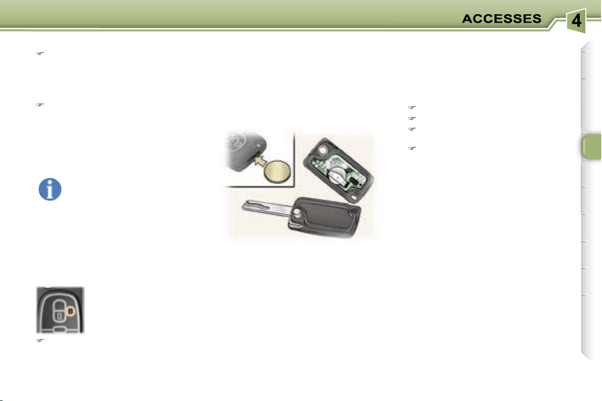
67
ELECTRONIC ENGINE
IMMOBILISER
This locks the engine control sys-
tem a few moments after the ignition
has been switched off and therefore
prevents starting of the vehicle by
anyone who does not have the key.
The ignition key has an electronic
chip which has a special code. When
the ignition is switched on, the code is
recognised and starting is possible.
If the system does not function cor-
rectly,
the service warning light comes
on, accompanied by an audible signal
and a message on the multifunction
display.
In this case, your vehicle will not start.
Contact a PEUGEOT dealer as soon
as possible.
Battery ref.: CR1620/3 volts.
The information "battery flat" is given
by displaying of the service warning
light, accompanied by an audible
signal and a message on the multi-
function display.
To replace the battery, unclip the cas-
ing using a coin at the notch.
If the remote control does not work
after the battery has been changed,
re-programme the remote control.
Key in ignition
A buzzer sounds on opening the
driver’s door, if the key has been left
in the ignition.
Reprogramming the remote
control
Following disconnection of the vehi-
cle’s battery, replacement of the re-
mote control battery or in the event
of a remote control malfunction, the
remote control must be reinitialised.
Switch off the ignition.
Switch the ignition on again.
Press the remote control locking but-
ton immediately for a few seconds.
Switch off the ignition and remove
the remote control key from the ig-
nition lock.
The remote control is now working
again.
Locating your vehicle
Using the key
Turn the key in the lock on the
driver’s door to lock the vehicle
and hold it in this position for more
than two seconds to activate the
automatic closing of the windows
in addition to locking.
Turn the key again within five sec-
onds to deadlock the vehicle.
Each action is confirmed by fixed
lighting of the direction indicators for
approximately two seconds.
When the vehicle is locked,
if unlocking is activated inad-
vertently without a door being
opened within 30 seconds,
the vehicle will lock automatically.
The folding and unfolding of the ex-
terior mirrors can be deactivated by
a PEUGEOT dealer.
To locate your vehicle, if
you have locked it, in a
car park:
press button
B
, the courtesy lights
come on and the direction indica-
tors flash for a few seconds.
Changing the remote control
battery
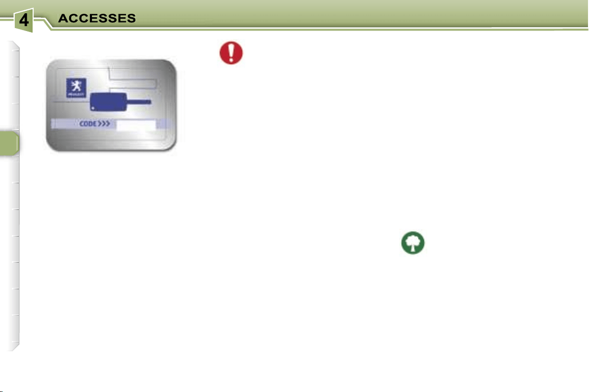
68
Make a careful note of the
number on each key. The key
number is coded on the label
attached to the key.
If the keys are lost, your PEUGEOT
dealer can rapidly supply you with
new keys.
The high frequency remote con-
trol is a sensitive system; do not
operate it while it is in your pocket
as there is a possibility that it may
unlock your vehicle, without you
being aware of it.
The remote control does not oper-
ate when the key is in the ignition,
even when the ignition is switched
off, except for reprogramming.
Do not operate the deadlocking
function if there is anyone inside
the vehicle.
Driving with the doors locked may
make access to the passenger com-
partment by the emergency services
more difficult in an emergency.
As a safety precaution (with chil-
dren on board), remove the ignition
key when you leave the vehicle,
even for a short time.
Do not repeatedly press the but-
ton of your remote control out of
range and out of sight of your ve-
hicle. You run the risk of stopping
it from working and the remote
control would have to be repro-
grammed.
When purchasing a second-hand
vehicle:
- ensure that you are given the
confidential card;
- have the key codes memorised
by a PEUGEOT dealer, to ensure
that the keys in your possession
are the only ones which can start
the vehicle.
Do not make any modifications to
the electronic engine immobiliser
system.
This is given to you on delivery of
your vehicle with the duplicate keys.
It contains the identification code
necessary for any work carried out
by a PEUGEOT dealer on the elec-
tronic immobiliser system. This code
is hidden by a film, which should be
removed only if necessary.
Keep your card in a safe place,
never inside the vehicle.
When undertaking a long trip or jour-
ney, however, it is advisable to take
it with you along with your personal
papers.
Do not throw the remote con-
trol batteries away, they con-
tain metals which are harmful
to the environment.
Take them to an approved collection
point.
CONFIDENTIAL CARD
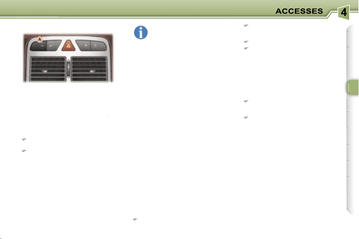
69
This provides two types of protection:
-
exterior protection:
it sounds if
a door, the boot or the bonnet is
opened.
-
interior protection:
it sounds if
the volume inside the passenger
compartment changes (breaking of
the volume inside the passenger
the volume inside the passenger
a window or a movement inside the
vehicle).
In the next ten seconds, press
button
A
until the indicator light is
on continuously,
Get out of the vehicle,
Set the alarm by locking or dead-
locking using the remote control
(button
A
indicator light flashes
once a second).
In order for the alarm to be set in
this mode, these operations must be
carried out each time the ignition is
switched off.
Setting the alarm
Switch off the ignition and get out
of the vehicle.
Set the alarm, by locking or dead-
locking using the remote control
(button
A
indicator light flashes
once per second).
Note:
if you wish to lock your vehi-
cle without setting the alarm, use the
door lock.
When the alarm is triggered, the si-
ren sounds and the direction indicator
lights flash for thirty seconds.
After triggering, the alarm remains set.
Disarming
Unlock the vehicle with the remote
control key (button
A
indicator light
goes out).
Note:
if the alarm has been triggered
while you were away from your vehicle,
the rapid flashing of the indicator light will
stop when you switch on the ignition.
If the alarm has been trig-
gered ten times in succes-
sion, on the eleventh time it
becomes inactive.
If button
A
indicator light flashes rap-
A
A
idly, the alarm has been triggered while
you were away from your vehicle.
45 seconds following pressing of the
locking button on the remote control,
the alarm is set, regardless of the
status of the doors or boot.
When washing your vehicle, to pre-
vent triggering of the alarm:
- lock the doors using the key,
or
- set the exterior alarm only.
To set the alarm with exterior
protection only
If, while you are away from the vehi-
cle, you wish to leave a window par-
tially open or a pet inside the vehicle,
you should choose exterior protec-
tion only.
Switch off the ignition,
THE ALARM
* According to country.
Failure of the remote control
Unlock the doors with the key and
open the door. The alarm is trig-
gered.
Switch on the ignition. The alarm
is disarmed.
Incorrect operation
When the ignition is switched on, if
button
A
lights for ten seconds, there
is a fault in the siren connection.
Contact a PEUGEOT dealer to have
the system checked.
Automatic activation*
The alarm is activated automatically
two minutes after the last closure of a
door or the boot.
In order to avoid accidental triggering
of the alarm when a door or the boot
is opened, it is essential to first press
the unlocking button on the remote
control.
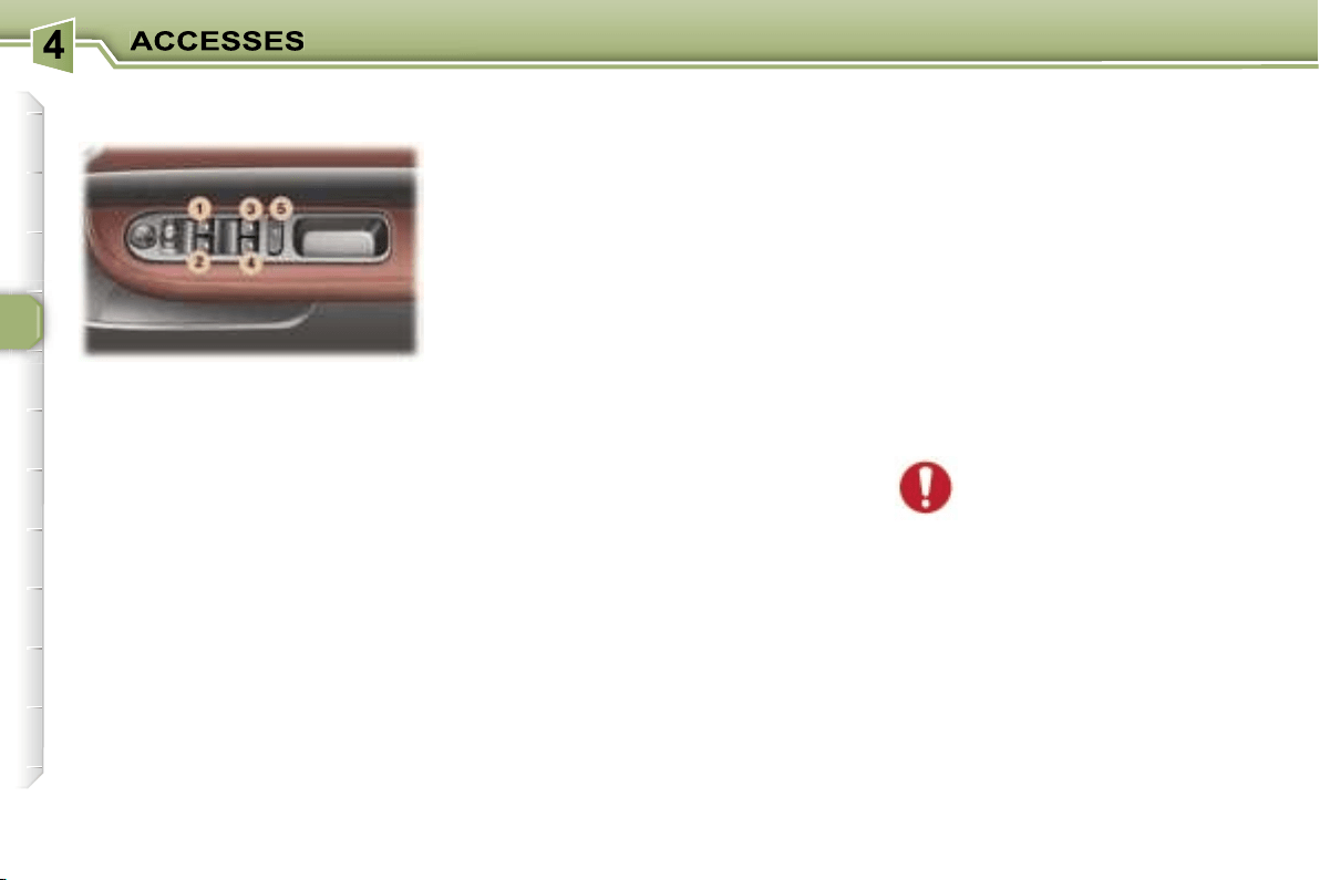
70
1. Driver’s electric window
switch.
2. Passenger’s
electric window
switch.
3.
Rear right electric window
switch.
4. Rear left
electric window
switch.
5. Disarming of the rear electric
window switches (child lock).
You have two options:
Automatic operation:
Press or pull the switch fully: the win-
dow opens or closes completely when
the switch is released. Pressing the
switch again stops the movement of
the window.
Note:
approximately 45 seconds fol-
lowing removal of the ignition key,
none of the windows can be opened
or closed. The ignition must be
switched on again to open or close
the windows.
Always remove the key from
the ignition when leaving
the vehicle, even for a short
time.
In the event of contact during opera-
tion of the windows, you must reverse
the movement of the window. To do
this, press the switch concerned.
When the driver operates the pas-
senger electric window switches, he
must ensure that no one is prevent-
ing correct closing of the windows.
The driver must ensure that the pas-
sengers use the electric windows
correctly.
Be aware of children when operating
the windows.
Reinitialisation of the
windows
Following reconnection of the battery
or in the event of a malfunction:
- release the switch and pull it again
until it closes completely,
- hold the switch for approximately
one second after closing,
- press the switch to lower the
window automatically,
- when the window has reached the
low position, press the switch again
for approximately one second.
The safety auto-reverse function
is not active during these opera-
tions.
Manual operation:
Press or pull the switch gently. The
window stops as soon as the switch
is released.
ELECTRIC WINDOWS
Safety auto-reverse
When the window rises and meets
an obstacle, it stops and partially
lowers again.
Disarming the rear window
controls
For the safety of your children, press
switch
5
to prevent operation of the
rear windows irrespective of their po-
sition.
When the button is pressed down,
disarming is active. When the button
is raised, disarming is deactivated.
Note:
In the event of unwanted opening
of the window on closing (for exam-
ple in the presence of frost), press
the switch until it opens completely,
then pull it immediately until it clos-
es. Continue to hold the switch for
approximately one second after the
window has closed.
The safety auto-reverse function is
not active during these operations.
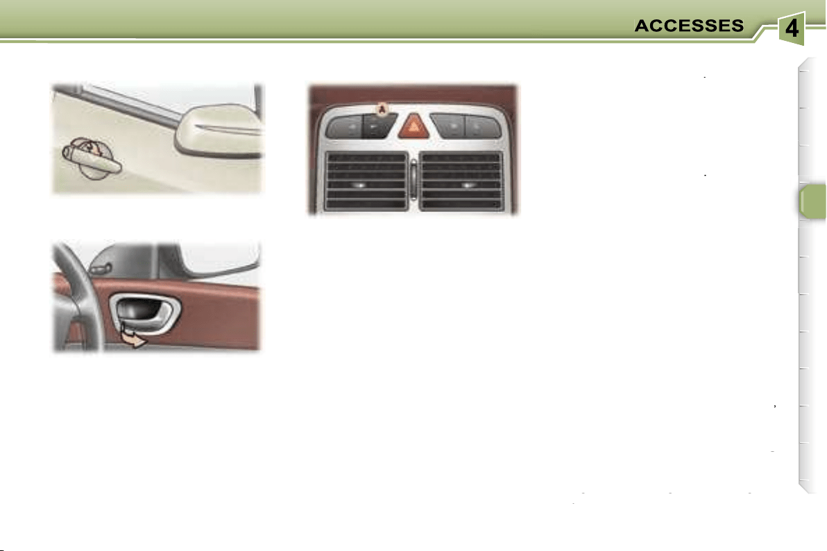
71
Opening the doors from inside
The door opening control permits
complete unlocking of the vehicle.
Note:
the door opening switches
do not function when the vehicle is
deadlocked.
Pressing button
A
permits locking or
unlocking of the vehicle.
The red warning light on the button
comes on when the vehicle is locked
and switches off when it is unlocked.
Note:
if the vehicle is locked or dead-
locked from outside, the red warning
light flashes and button
A
does not
function. In this case, use the key or
the remote control for unlocking.
THE DOORS
Opening the doors from outside
To switch on
Press and hold button
A
.
Activation of the function is accom-
panied by a message on the multi-
function display.
Automatic central locking of the
doors
The doors can lock automatically
when you are driving (at a speed of
more than 6 mph (10 km/h)).
Above 6 mph (10 km/h), press button
A
briefly to unlock the doors tempo-
rarily.
You can activate or deactivate this
function.
To switch off
Press and hold button
A
.
Deactivation of the function is ac-
companied by a message on the
multifunction display.
"Door open" alert
If a door has not been closed properly:
-
when the engine is running
,
you are warned by a diagram and
a message on the multifunction
you are warned by a diagram and
you are warned by a diagram and
display for a few seconds,
a message on the multifunction
a message on the multifunction
-
when the vehicle is moving
(speed above 6 mph (10 km/h)),
when the vehicle is moving
when the vehicle is moving
the service warning light comes on.
This is accompanied by an audible
signal, a message and a diagram
on the multifunction display for a
signal, a message and a diagram
signal, a message and a diagram
few seconds.
on the multifunction display for a
on the multifunction display for a
Notes:
If one of the doors is open, locking
from the inside and automatic central
locking are not possible.
If the boot is open, automatic central
locking of the doors is active.
Locking/
Unlocking from the inside

72
This prevents either of the rear doors
being opened from inside.
Turn the switch a quarter of a turn
using the ignition key.
"Tailgate open" warning
If the tailgate has not been closed
properly:
-
when the engine is running
,
you are warned by a diagram and
a message on the multifunction
display for a few seconds,
-
when the vehicle is being driven
(speed above 6 mph (10 km/h)),
the service warning light comes on.
This is accompanied by an audible
signal, a diagram and a message
on the multifunction display.
Simultaneous locking or
unlocking of the tailgate and
the doors
The tailgate is locked or unlocked
by the remote control or the driver’s
door lock.
To open, pull handle
A
and lift the
tailgate.
Note:
the tailgate locks automati-
cally when the vehicle is being driven
above 6 mph (10 km/h). It unlocks
when one of the doors is opened or
when the internal central locking/un-
locking button is pressed (speed be-
low 6 mph (10 km/h)).
TAILGATE
Child safety
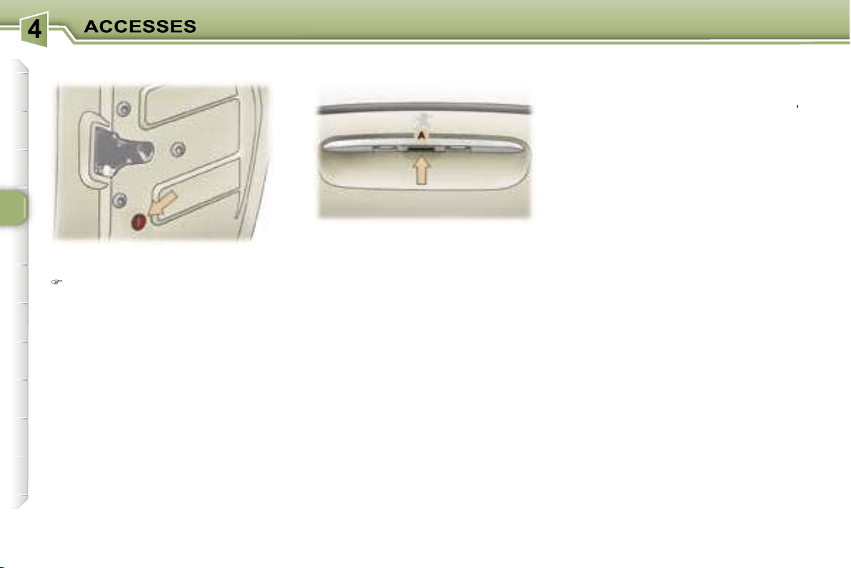
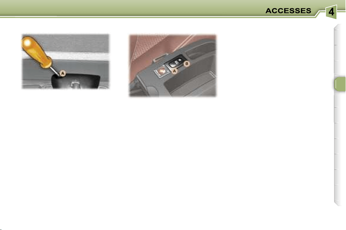
73
This enables the tailgate to be un-
locked in the event of a central locking
fault.
- Fold back the rear seats to gain
access to the lock
from inside the
boot,
- Insert a small screwdriver into hole
A
of the lock to unlock the tailgate.
Safety auto-reverse
At the end of its travel, if the shutter
encounters an obstacle to closing, it
stops and moves back slightly.
Your vehicle is fitted with a tinted
glass panoramic roof which increas-
es the light and visibility in the pas-
senger compartment. Its electric con-
cealing shutter improves temperature
conditions.
To open:
press part
A
of the switch.
To close:
press part
B
of the switch.
Manually:
press the switch without
going past the point of resistance; the
shutter stops as soon as the switch is
released.
Automatically:
press the switch
beyond the point of resistance; one
press fully opens or closes the shut-
ter. Press the switch again to stop the
shutter.
Notes
If the shutter’s power supply is cut
off, while it is moving or immediately
after it has stopped, you must reini-
tialise the safety auto-reverse:
- press section
B
of the switch until the
shutter is completely closed (closing
in stages of a few centimetres).
In the event of unwanted opening of
the shutter on closing, and immedi-
ately after the shutter has stopped:
- press section
A
of the switch until
the shutter is fully open,
- release section
A
and immediately
afterwards press section
B
of
the switch until the shutter is fully
closed (closing in stages of a few
centimetres).
The safety auto-reverse function
is not active during these opera-
tions.
PANORAMIC ROOF
Tailgate release
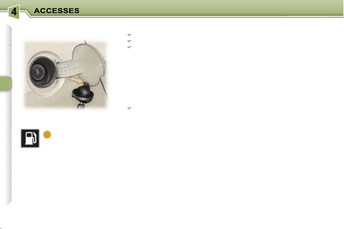
74
The engine must be switched off
when filling with fuel.
Open the fuel filler flap.
Insert the key then turn it to the left.
Remove the cap and hang it on
the hook located on the inside of
the flap.
A label affixed to the inside of the fuel
filler flap indicates which type of fuel
to use.
When you fill your tank, do not con-
tinue after the third cut-off of the
pump. This could cause your vehicle
to malfunction.
The capacity of the tank is approxi-
mately 60 litres.
After filling the tank, lock the cap
and close the fuel filler flap.
Low fuel level
When the minimum
fuel level in the tank
is reached, this
warning light comes
on on the instrument
panel.
You can still drive approximately
30 miles (50 km).
Operating fault
With the ignition on, if the fuel gauge
needle remains in or returns to the
rest positon (below zero), this in-
dicates a malfunction of the fuel
gauge.
Contact a PEUGEOT dealer.
FILLING WITH FUEL
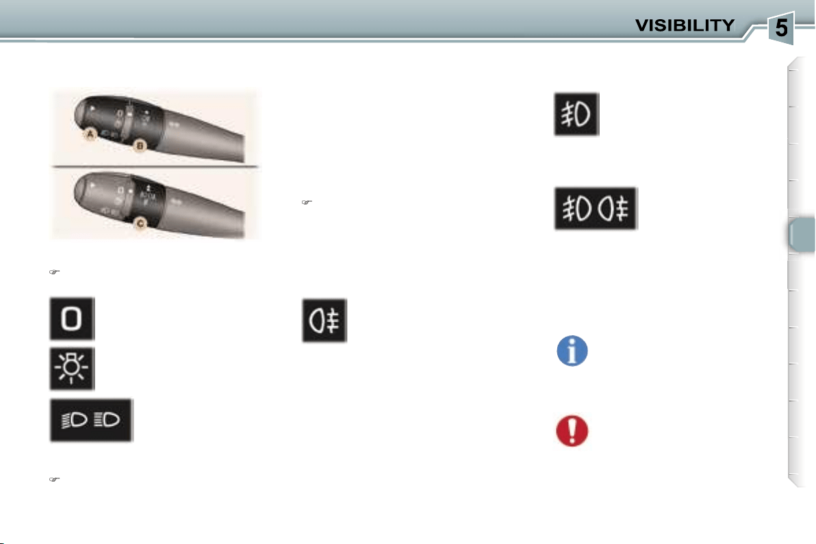
75
Front and rear lights
(ring A)
Place ring
A
in the required
position.
Dipped/Main beam change
Pull the stalk towards you.
Vehicles fitted with front fog
lamps and a rear fog lamp (ring C)
Lights off
Side lights
Dipped/main beam
headlamps
Rear fog lamp
Front fog lamps (first rota-
tion of the ring forwards)
Front and rear fog
lamps (2nd rotation
of the ring forwards).
Note:
to switch off the rear fog lamp
and the front fog lamps, turn the ring
backwards twice in succession.
Vehicles fitted with a rear fog
lamp (ring B)
This operates with the dipped/main
beam headlamps.
Note:
when the lights are switched off
automatically, the rear fog lamp and
the dipped headlamps will remain on.
Turn the ring backwards to switch off
the rear fog lamp. The dipped head-
lamps will then be switched off.
The front fog lamps operate with
the side lights and the dipped head-
lamps.
Front fog lamps and rear fog
lamp
Turn ring
B
or
C
forwards to switch
on and backwards to switch off.
The status is confirmed by the
indicator light on the instrument
panel.
Lights on buzzer
With the ignition off and the automat-
ic switching on of the lights deactivat-
ed, when the driver’s door is opened,
a buzzer sounds to warn you that you
have left your lights on.
In good or rainy weather,
both day and night, the front
fog lamps and the rear fog
lamp are dazzling and are
prohibited.
Do not forget to switch them off when
they are no longer needed.
LIGHTS STALK
The rear fog lamp will be de-
activated automatically when
towing or when a bicycle car-
rier fitted with a fog lamp is
fitted.

76
Automatic switching on of the
lights
Side lights and dipped beam head-
lamps switch on automatically if the
light is poor, or during operation of
the windscreen wipers. They switch
off as soon as the light becomes
bright enough or the windscreen wip-
ers stop.
Note:
in foggy weather or in snow,
the brightness sensor can detect suf-
ficient light. As a consequence, the
lights will not come on automatically.
Deactivation
The deactivation of this function is
accompanied by a message on the
multifunction display.
The function is deactivated tempo-
rarily when you use the manual lights
stalk.
Manual "Follow-me-home" lighting
When the automatic switching on
of the lights function is deactivated
,
the side lights and dipped headlamps
remain on for the duration selected for
the automatic "follow-me-home" lighting.
If the vehicle is not fitted with the
automatic switching on of the lights
function
, when you leave your vehicle,
the side lights and dipped headlamps
remain on for thirty seconds.
Direction indicators (flashers)
Left:
downwards.
Right:
upwards.
Note:
if you forget to cancel the di-
rection indicator, the volume of the
audible signal will increase, if you
are driving at a speed greater than
50 mph (80 km/h).
Automatic "Follow me home"
lighting
With the ignition off, when you leave
your vehicle with the
automatic
switching on of the lights function
activated
, the side lights and dipped
headlamps remain on for the select-
ed duration.
Activation:
switch off the engine,
"flash" the headlamps,
get out of the vehicle and lock it.
Deactivation:
"flash" the headlamps again,
get out of the vehicle and lock it.
To deactivate or activate
this function, go to the multi-
function display configura-
tion menu.
The duration of the timed
period must also be set (15, 30,
60 seconds), via the multifunction
display configuration menu, except
in the case of the
monochrome
screen A
for which it is pre-set.
Cancelling:
"flash" the headlamps,
get out of the vehicle and lock it.
To switch the function on
or off, use the multifunction
display configuration menu.
Activation
The activation of this function is
accompanied by a message on the
multifunction display.
The function is activated when the
manual lights stalk is in position
0
.
If the brightness sensor does not
function correctly
, the lights come
on accompanied by the service
warning light, an audible signal and
a message on the multifunction
display.
Contact a PEUGEOT dealer.
Do not cover the brightness
sensor, coupled with the rain
sensor, located in the centre
of the windscreen, behind
the interior mirror. It is used for the
automatic switching on of the lights.
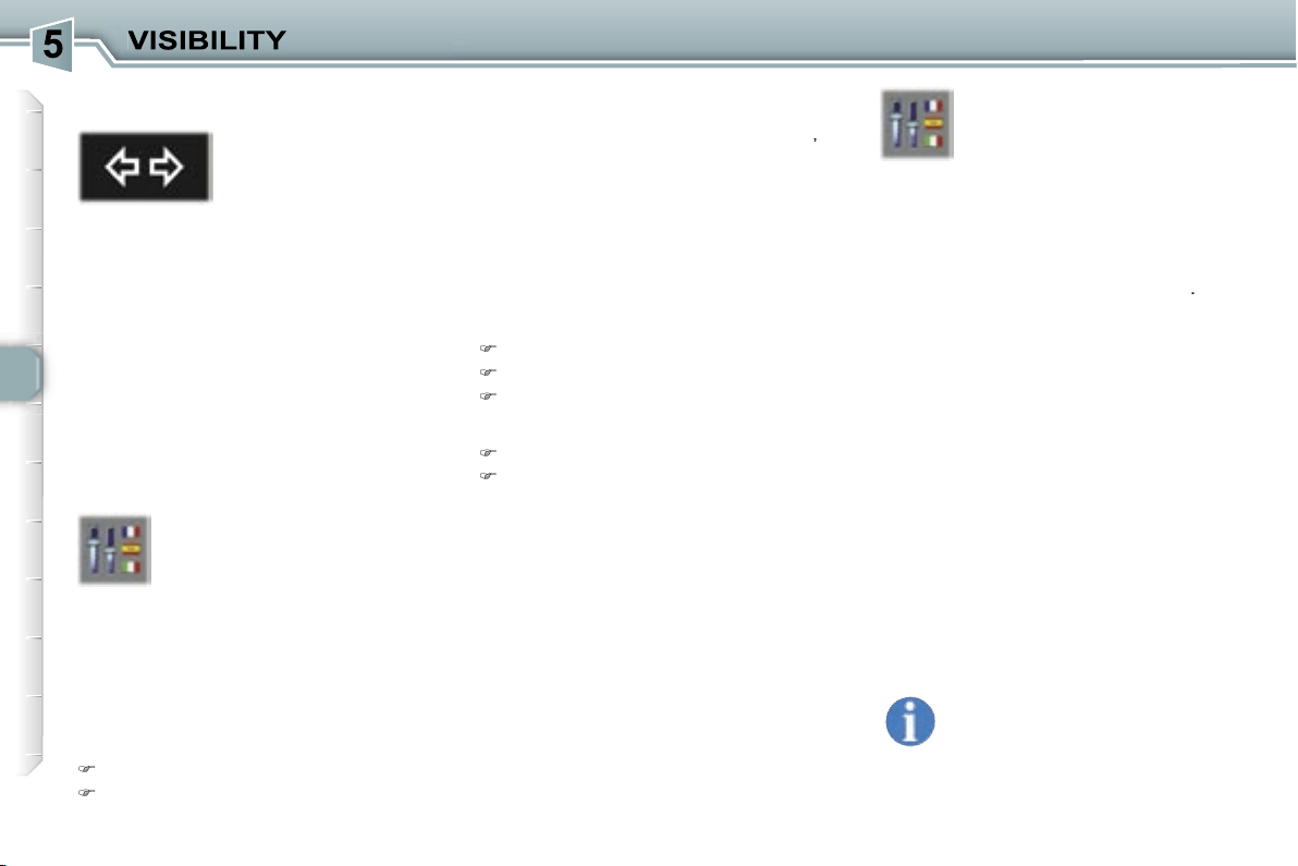
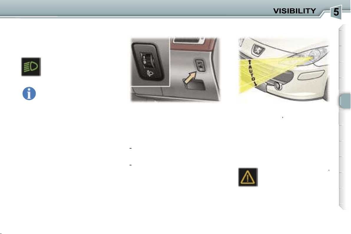
77
For vehicles fitted with halogen
bulbs, depending on the load in your
vehicle, adjusting the beam of your
headlamps is recommended.
0.
1 or 2 people in the front seats.
-.
3 people.
1.
5 or 7 people.
-
.
Intermediate setting.
2.
5 or 7 people + maximum
authorised load.
-
.
Intermediate setting.
3.
Driver + maximum authorised
load.
Initial setting is position 0.
On vehicles with xenon bulbs:
when stationary
,
the system auto-
matically corrects the height of the
beam, whatever the load of the vehi-
cle. The driver is then assured of hav-
ing optimum lighting and not causing
a nuisance to other road users.
In cases of malfunction
,
the service warning light
comes on on the instrument
panel, accompanied by an
audible signal and a mes-
sage on the multifunction display.
The system places your headlamps
to the low position.
Do not touch the xenon bulbs.
Contact a PEUGEOT dealer.
Daytime lights*
On vehicles which are equipped with
daytime lights, the dipped headlamps
come on when the vehicle is started.
* According to country.
The instruments and controls
(instrument panel, multifunc-
tion display, air conditioning
control panel, ...) are only lit
on switching to the automatic switch-
ing on of the lights mode or when the
lights are switched on manually.
This warning light comes
on on the instrument panel.
MANUAL ADJUSTMENT OF
THE HEADLAMPS
AUTOMATIC HEADLAMP
ADJUSTMENT
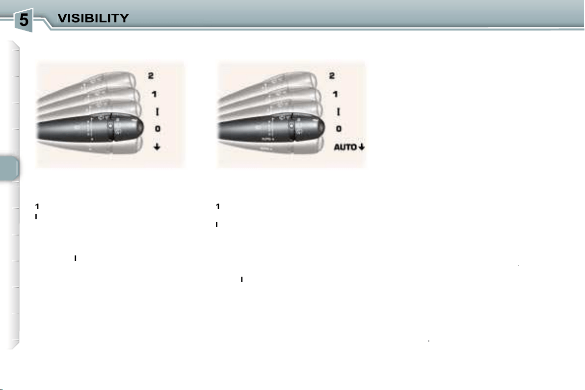
78
Special position of the front
windscreen wiper
In the minute following switching off
of the ignition, any action on the stalk
positions the wipers in the centre of
the windscreen.
This action enables you to position
the wiper blades for winter parking,
cleaning or replacement (See section
"Practical information - Changing a
wiper blade").
To park the wipers after this has
been done, switch on the ignition and
operate the stalk.
Windscreen and headlamp wash
Pull the windscreen wiper stalk to-
wards you. The windscreen wash
then the windscreen wipers operate
for a fixed period.
The headlamp wash is also activat-
ed,
if the headlamps are on
.
Automatic windscreen wipers
In
AUTO
mode, the windscreen wip-
ers operate automatically and
adapt
their speed to the intensity of the
rainfall
.
Front windscreen wiper with
automatic wipe
2
Fast wipe (heavy rain).
1
Normal wipe
(moderate rain).
I
Intermittent wipe.
0
Off.
AUTO
Automatic or single wipe
(press downwards).
In the
I
ntermittent position, the wiping
speed is in proportion to the speed of
the vehicle.
In
AUTO
mode, the wiping speed is
in proportion to the intensity of the
rainfall. The first press of the stalk
downwards activates the automatic
wipe.
Subsequent presses trigger a single
wipe.
WINDSCREEN WIPER STALK
Front windscreen wiper with
intermittent wipe
2
Fast wipe (heavy rain).
1
Normal wipe (moderate rain).
l
Intermittent wipe.
0
Off.
Single wipe (press downwards).
In the
I
ntermittent position, the
wiping speed is in proportion to the
vehicle speed.
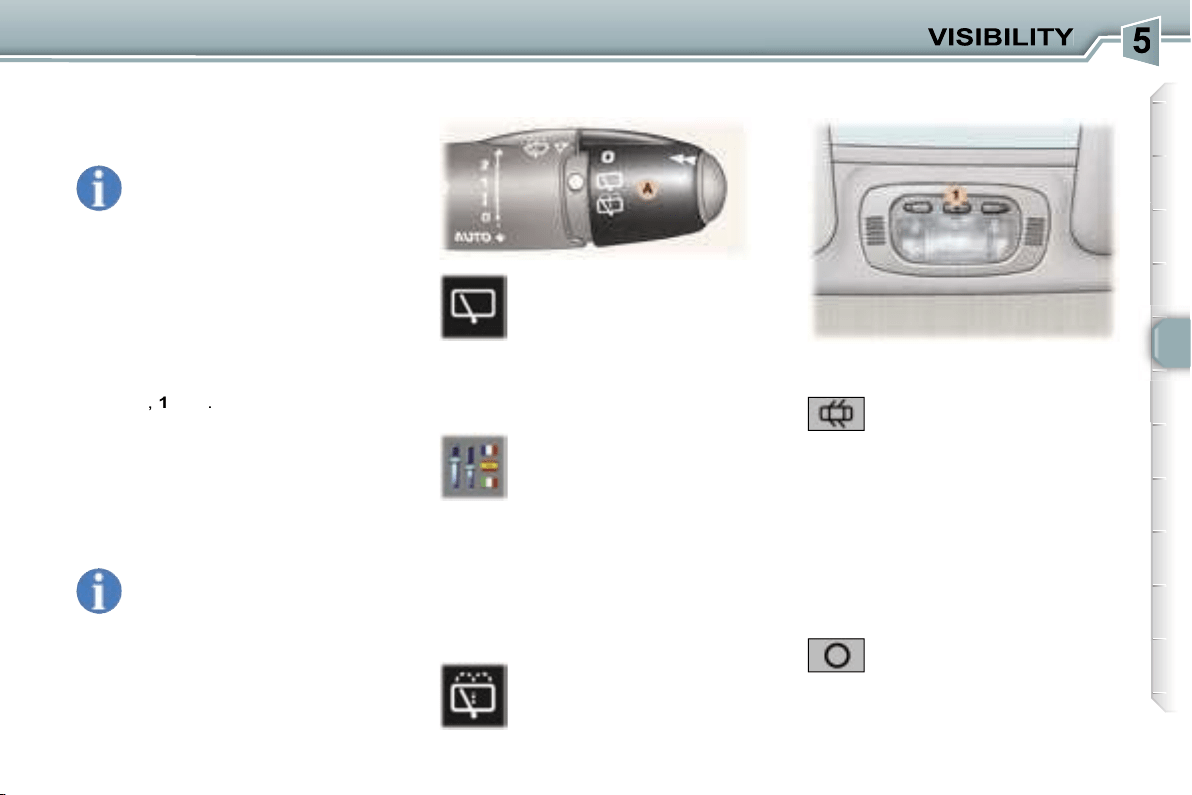
79
Do not cover the rain sensor
located on the windscreen
behind the interior mirror.
When using an automatic car
wash, switch off the ignition.
In winter, it is advisable to wait for the
windscreen to completely clear of ice
before operating the automatic wipe.
Activation
Activation of the function is accom-
panied by a message on the multi-
function display.
Turn ring
A
to the first notch
for intermittent wiping.
When reverse gear is en-
gaged, if the windscreen
wipers are in operation, the
rear wiper will start wiping.
To activate or deactivate
this function, go to the multi-
function display configura-
tion menu.
If there is a significant accumulation
of snow or ice and when using a bicy-
cle carrier on the tailgate, deactivate
the automatic rear wiping by going to
the multifunction display configura-
tion menu.
Turn ring
A
past the first
notch; the windscreen wash
then the windscreen wiper
operate for a fixed period.
Deactivation
Deactivation of the function is ac-
companied by a message on the
multifunction display.
The function is deactivated when the
windscreen wipers stalk is moved to
position
I
,
1
or
2
.
In the event of malfunction
of the
automatic windscreen wipers, the
windscreen wipers will operate in in-
termittent mode.
Contact a PEUGEOT dealer to have
the system checked.
Rear windscreen wash
1. Front courtesy light
In this position, the courtesy
light comes on automatically:
- when the vehicle is unlocked,
- when the key is removed from the
ignition,
- when a door is opened,
- when the vehicle location function is used.
Permanently off.
It switches off gradually:
- when the vehicle is locked,
- when the ignition is switched on,
- with the ignition off, 30 seconds
after the last door is closed.
COURTESY LIGHTS
Rear windscreen wiper
The automatic windscreen
wipers function must be
reactivated if the ignition
has been switched off for
more than one minute, by press-
ing the stalk downwards.
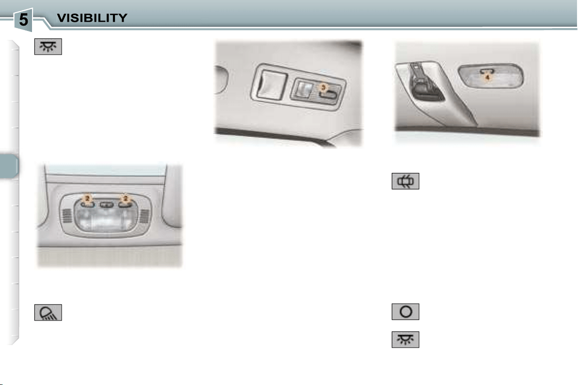
80
3. 2nd row rear reading lights
Permanently off.
The reading light comes on:
- when the vehicle is unlocked,
- when the key is removed from the
ignition,
- when a door is opened,
- when the vehicle location function
is used.
It switches off gradually:
- when the vehicle is locked,
- when the ignition is switched on,
- with the ignition off, 30 seconds
after the last door is closed.
With the ignition on (function not avail-
able in economy mode), press the
switch to obtain permanent lighting.
Press the switch again to switch the
reading light off.
In this position, the courtesy
light comes on automatically:
4. 3rd row rear courtesy light
Permanently on when the
ignition is on (function not
available in economy mode).
- when the vehicle is unlocked,
- when the key is removed from the
ignition,
- when a door is opened,
- when the vehicle location function
is used.
It switches off gradually:
- when the vehicle is locked,
- when the ignition is switched on,
- with the ignition off, 30 seconds
after the last door is closed.
Permanently on.
2. Front map reading lights
Different lighting times are available:
- with the ignition off or on,
approximately 10 minutes,
- in economy mode, approximately
30 seconds,
- when the engine is running, no
limit.
With the ignition on, press
the corresponding switch.
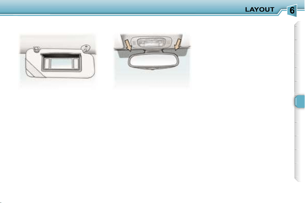
81
With the ignition on, the mirror is
automatically lit up when the flap is
opened.
The athermic windscreen has two non-
reflective zones located either side of
the base of the interior mirror.
They are intended for affixing toll
cards and/or car park tickets.
S
UN VISOR WITH ILLUMINATED
COURTESY MIRROR
AREAS FOR TOLL CARDS/
CAR PARK TICKETS
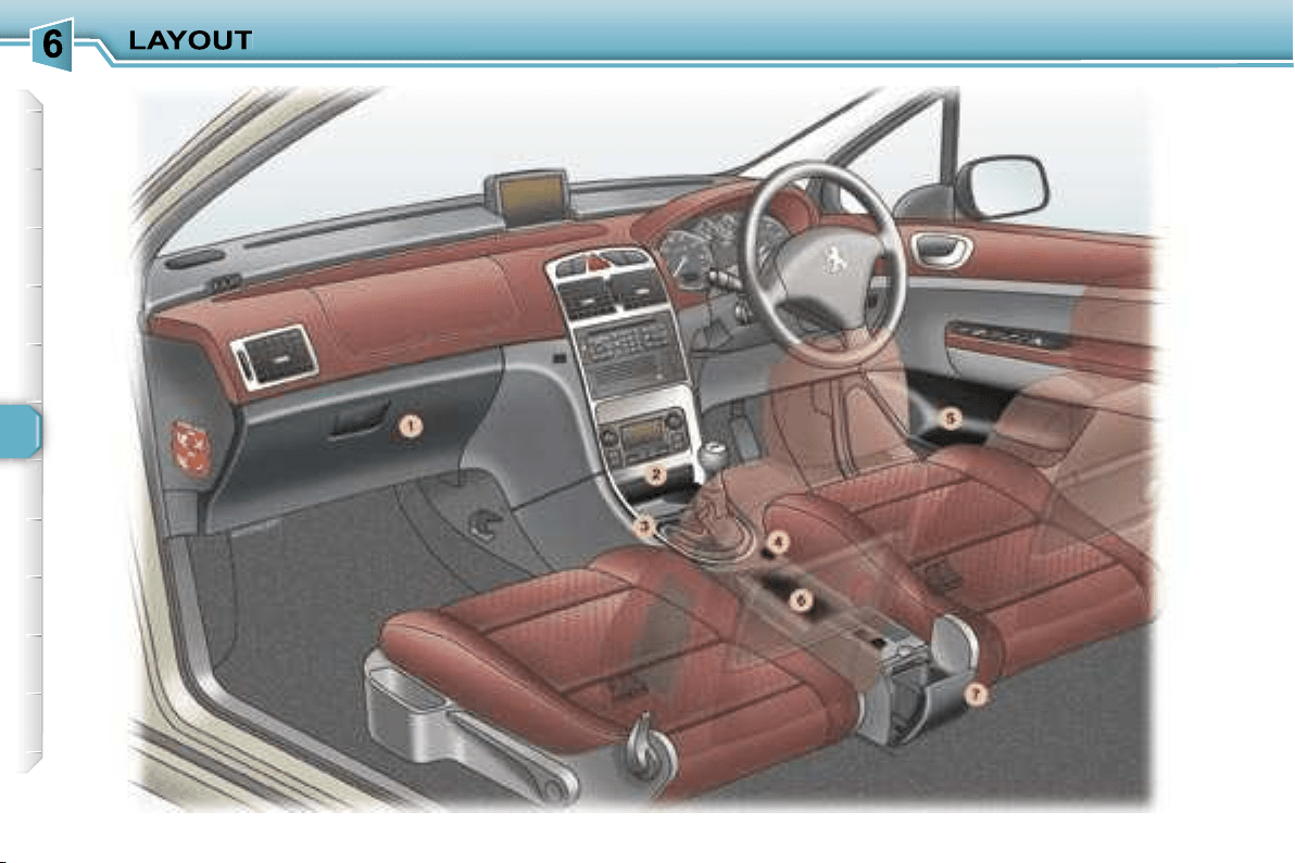
82
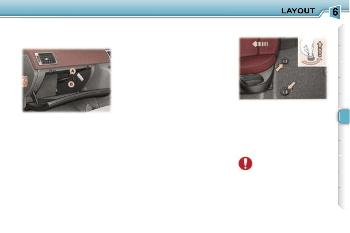
83
INTERIOR LAYOUT
2. Front ashtray
Pull the lid to open the ashtray.
To empty it after opening, press the
tab and remove the ashtray.
3. Storage
4. 12 volt socket (100 W max)
This is a lighter type socket, fitted
with a cap. It is supplied with current
from the running position.
5. Door tray
6. Storage/
C
an holder
7. Waste container
To empty, open it fully (past the point
of resistance) then pull on the recep-
tacle to remove it.
To refit, lock it in place on the cover.
This is fitted with a lock.
To open the glove box, lift the han-
dle.
The glove box lights when the lid is
opened.
It has a ventilation nozzle that can
be closed
A
, distributing the same
cooled air as the vents of the pas-
senger compartment.
It contains three sockets*
B
for con-
necting video equipment.
The layout allows storage of a water
bottle, a pen, the vehicle handbook,
a pair of spectacles, tokens, etc.
When fitting the mat for the first time,
use only the fixings supplied in the
wallet attached.
When removing the mat on the driv-
er’s side:
- push the seat as far back as pos-
sible,
- unscrew the fixings fully,
- remove the fixings, then the mat.
* DT colour screen only.
1. Glove box with cooling facility
FITTING/REMOVING THE MAT
When refitting, position the
mat correctly and replace the
fixings by pressing them in.
Ensure that the mat is secured correctly.
To prevent the mat from becoming
caught under the pedals:
- only use mats which are suited to
the fixings already present in the
vehicle. It is imperative that these
fixings are used.
- never fit one mat on top of another.
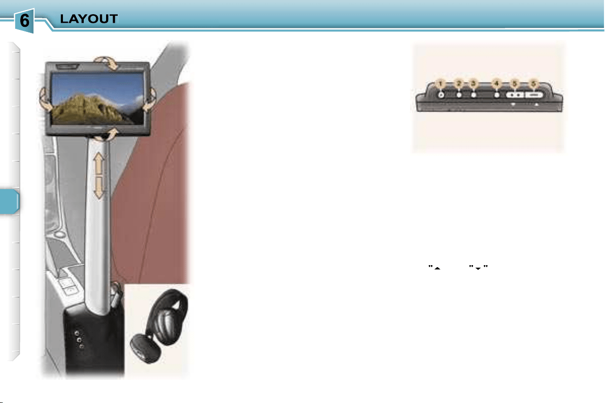
84
ENTERTAINMENT SCREEN KIT
This video assembly will enable the
rear passengers to pass the time
pleasantly while watching their fa-
vourite film or playing their favourite
game, by means, in particular, of the
connection of a DVD player or games
console to the central support, fitted
between the front seats.
The entertainment screen kit con-
sists of:
- a 16/9ths, 7 inch, LCD colour monitor
with direction adjustment in the three
axes,
- two high frequency, wireless, ster-
eo headphones,
- a removable support,
- three audio/video sockets on the
fixed base and in the glove com-
partment.
The monitor and the support can be
removed and stored, each in their
own protective cover.
The entertainment screen kit accepts
all types of audio/video source, PAL/
NTSC compatible, such as: DVD
player, camcorder, games console, ...
These sources are connected to the
three audio/video sockets,
AV1
in the
glove compartment or
AV2
on the
fixed base.
The upper face of the monitor incor-
porates the following controls:
1.
"POWER" button to switch the
monitor on/off.
2.
"FUNC" button for selection of
the input source, AV1 or AV2.
3.
"WIDE" button to change the
display format (normal, full
screen, wide, cinema).
4.
"MENU" button for selection of
the menus and settings.
5.
"
"
and
"
"
buttons to change
the settings.
By pressing buttons
4
and
5
, you can
adjust the brightness, the contrast,
the colours, ...
For further details, refer to the oper-
ating manuals "Video kit operation"
and "VMA8582 7 inch LCD colour
monitor".
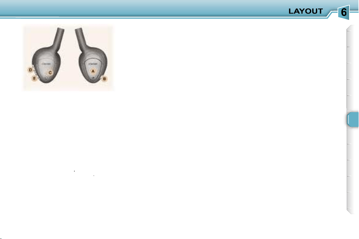
85
Various controls are incorporated in
the headphones:
A.
Housing for the two LR03
batteries.
B.
Headphones on/off button.
C.
On/off indicator light.
D.
Tuning frequency adjustment
control.
E.
Headphones volume adjustment
control.
To get the best out of the head-
phones, you must adjust their size to
suit you, find their tuning frequency
by rotating control
D
,
then adjust the
volume by rotating control
E
.
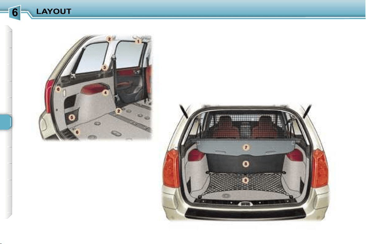
86

87
BOOT LAYOUT
4. Rear armrests with
grab handle
5. Storage nets
One of them contains the luggage re-
taining net.
6. Luggage retaining net
fastenings ("hammock"
version) in the tailgate
Fold the net in two.
Secure the two centre hooks in the
stowing rings on the floor.
Secure the net’s remaining four
hooks on the boot pillars.
7. Load space cover
To install it:
- position one end of the cover roller
in the 2nd row,
- compress the opposite end of the
roller and position it,
- release it to allow it to engage,
- unroll the cover as far as the boot
pillars,
- insert the cover guides in the rails
in the pillars,
To remove it:
- remove the cover guides from the
pillar rails,
- return the cover into its roller,
- compress it and remove it from its
support at the 2nd row,
To store it, pull it back and place it
with the two storage nets, already
lowered.
Note:
the roller has two hooks for se-
curing the luggage retaining net de-
pending on where it is installed.
8. High load retaining net
9. Luggage retaining net
Secure the net’s seven hooks in the
stowing rings and the fastenings on
the floor.
See configuration of the nets (next
page)
1. Grab handles and coat hooks
2. High load retaining
net fastenings
The high load retaining net can be fit-
ted in the 2nd or 3rd row.
Open the covers of the correspond-
ing upper fastenings.
Fit the ends of the metal bar in these
fastenings.
Secure the two opaque material
strap hooks in the stowing rings on
the floor.
The rings are located directly below
the corresponding upper fastenings.
Pull the two straps taut.
Secure the two hooks on the elastic
parts of the opaque material in these
rings.
Note:
the net must be positioned so
that the label can be seen from the
boot. This ensures that the central
seat belt is routed correctly.
3. 12 volt socket
This is a 12 volt socket (lighter type),
installed on the load space cover left
support.
It is supplied from the "Running" po-
sition.
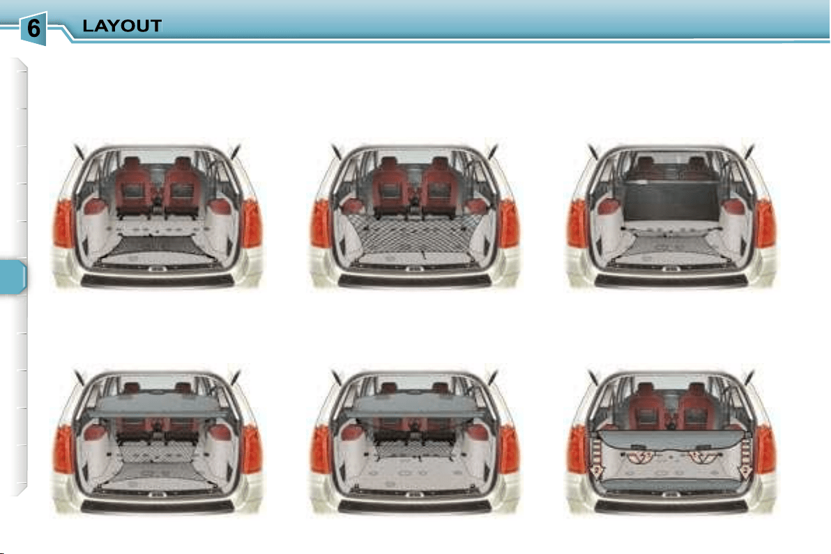
88
Example of installation of the nets:
Luggage retaining net, "folded"
version
Luggage retaining net, "L"
version
Luggage retaining net,
"hammock" version, in the
tailgate
Luggage retaining net,
"hammock" version at the roller
High load retaining net
in the 2nd row
Load space cover stored with the
two storage nets
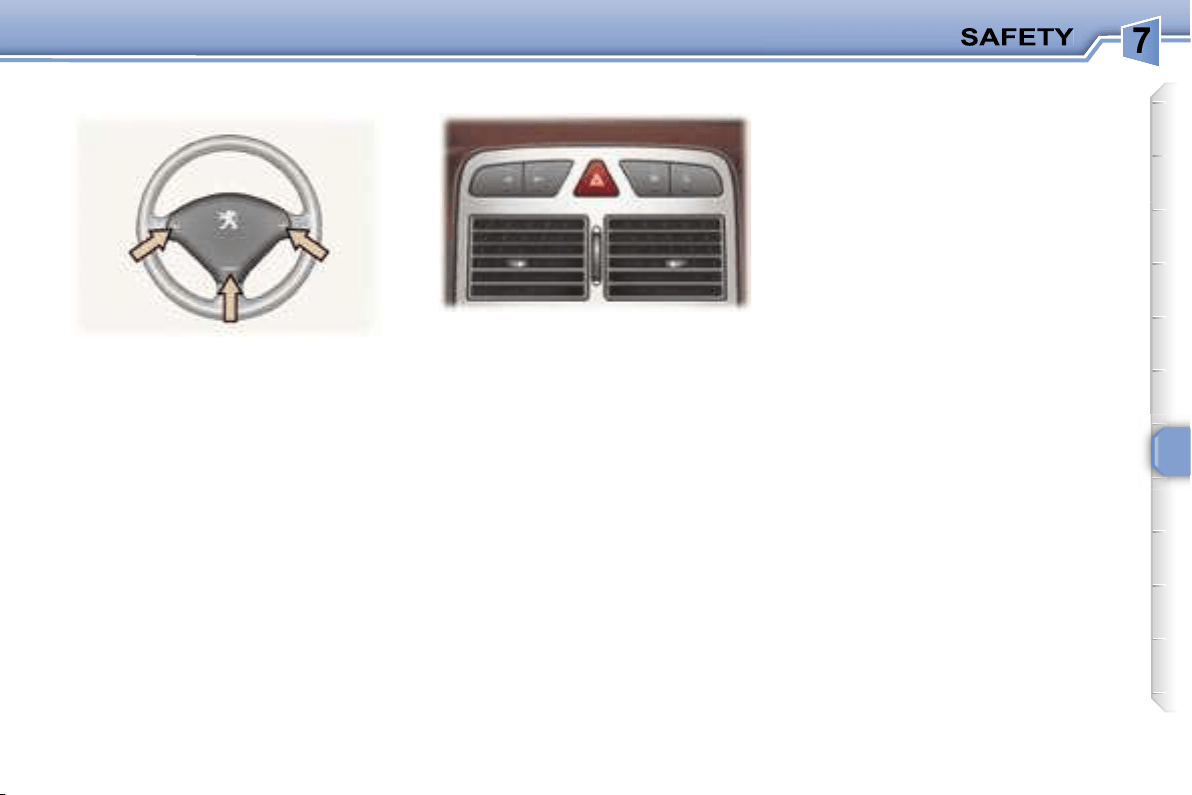
89
Press the button, the direction indica-
tors flash.
They can operate with the ignition off.
Press one of the spokes of the
steering wheel.
Automatic lighting of hazard
warning lights*
When braking in an emergency,
depending on the deceleration, the
hazard warning lights come on auto-
matically. They switch off automati-
cally the first time you accelerate.
It is also possible to switch them off
by pressing the button.
* According to country.
HAZARD WARNING LIGHTSHORN
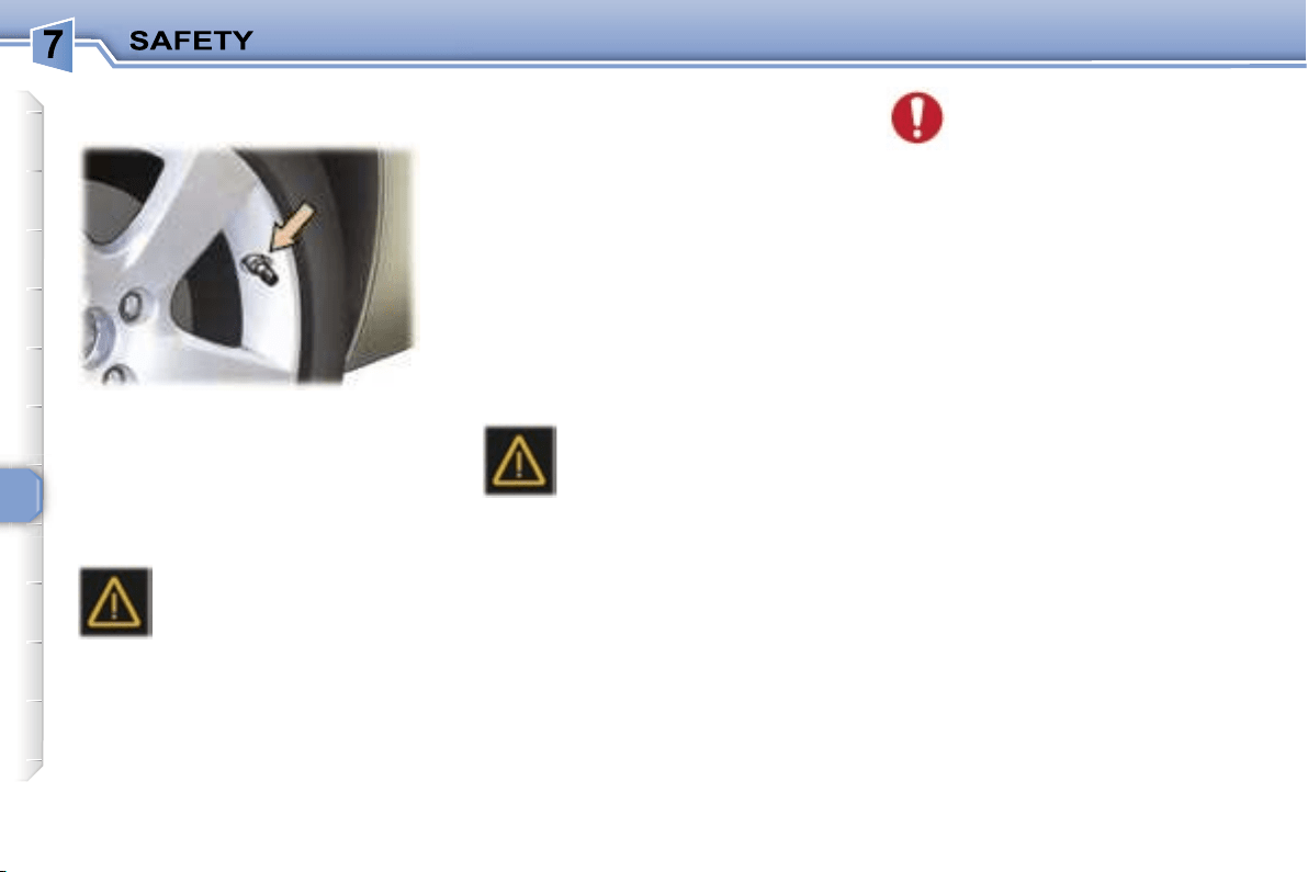
90
Sensors fitted in each valve check the
tyre pressure during driving and trigger
a warning in the event of malfunction
(speed above 12 mph (20 km/h)).
The service warning light
comes on on the instrument
panel, accompanied by an
audible signal and a message
on the multifunction display lo-
cating the wheel concerned.
Check the tyre pressures as soon as
possible. This check must be carried
out when the tyres are cold.
Puncture
The
STOP
warning light comes on on
the instrument panel, accompanied
by an audible signal and a message
on the multi-function display locating
the wheel concerned.
Stop immediately, avoiding any sud-
den movement of the steering wheel
and the brakes.
Change the damaged wheel (punc-
tured or very deflated tyre), and have
the tyre pressure checked as soon
as possible.
The service warning light
comes on on the instrument
panel, accompanied by an
audible signal and a mes-
sage on the multifunction
display locating the wheel or wheels
which are not detected or indicating a
fault in the system.
Contact a PEUGEOT dealer to re-
place the faulty sensor(s).
All repairs and changing of
tyres on a wheel fitted with
this system must be carried
out by a PEUGEOT dealer.
If, when changing a tyre, you
install a wheel which is not detect-
ed by your vehicle (example: fitting
of snow tyres), you must have the
system reinitialised by a PEUGEOT
dealer.
The tyre under-inflation detection
system is an aid to driving which does
not replace the need for the driver to
be vigilant or to drive responsibly.
This system does not eliminate
the need to have the tyre pressure
checked regularly (see manufactur-
er’s label on the door pillar) to ensure
that the optimum dynamic perform-
ance of the vehicle is maintained and
prevent premature wear of the tyres,
particularly in arduous driving condi-
tions (heavy load, high speed).
The tyre pressures must be checked
cold, at least once a month.
Remember to check the pressure of
the spare wheel.
The tyre under-inflation detection
system may experience temporary
interference due to radioelectric
emissions on a frequency close to
that used by the system.
Flat tyre
Sensor(s) not detected or faulty
Notes:
This message is also displayed when
one of the wheels is away from the
vehicle (being repaired) or when one
or more wheels without a sensor are
fitted.
The spare wheel is not fitted with a
sensor.
TYRE UNDER-INFLATION
DETECTION
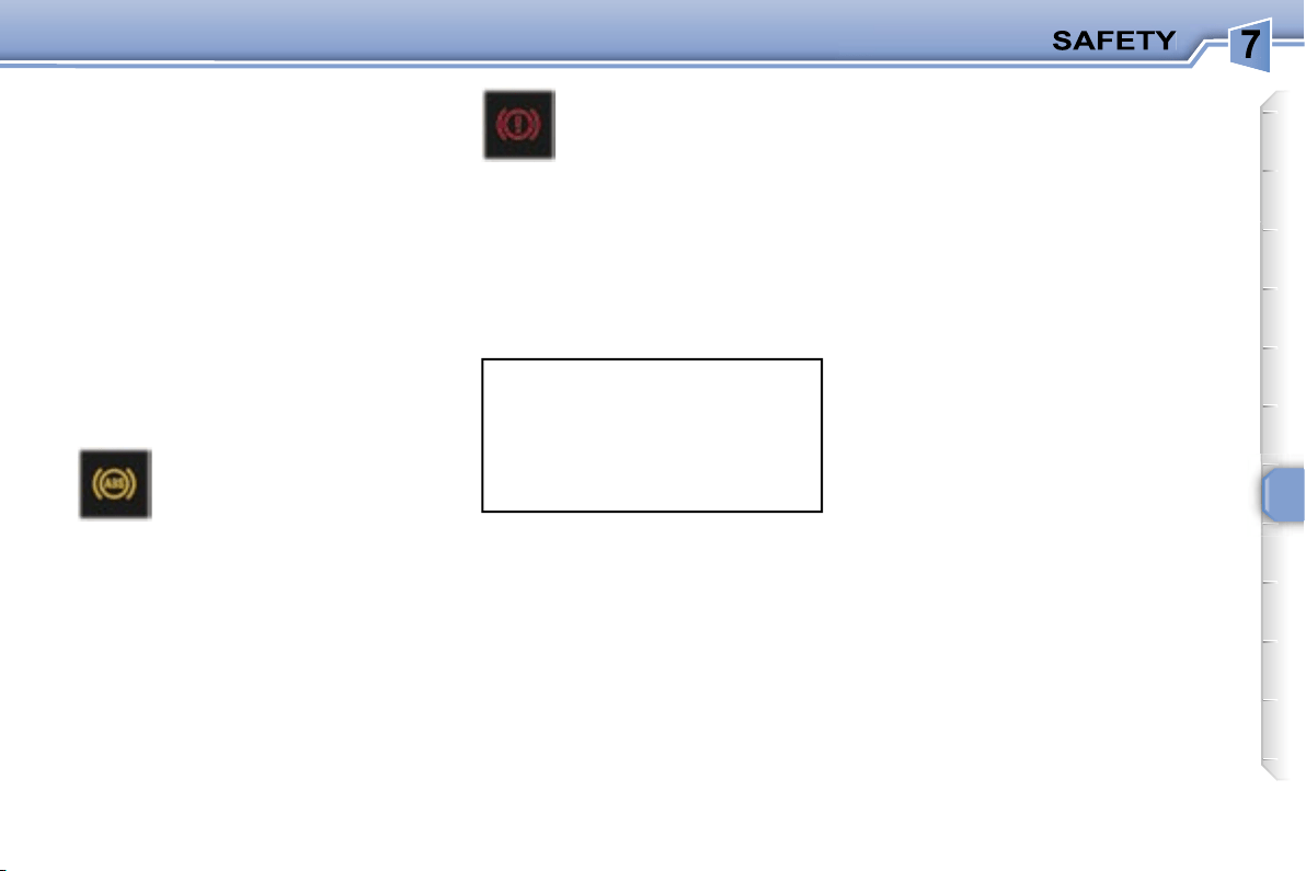
91
ANTI-LOCK BRAKING
SYSTEM (ABS) AND
ELECTRONIC BRAKE FORCE
DISTRIBUTION (EBFD)
The ABS, in conjunction with the
electronic brake force distribution,
increases the stability and mano-
evrability of your vehicle on braking,
in particular on poor or slippery road
surfaces.
Note:
when changing wheels (tyres
and rims), make sure that these are
approved.
The anti-lock braking system comes
into operation automatically when
there is a risk of wheel lock.
EMERGENCY BRAKING
ASSISTANCE SYSTEM
In an emergency, this system enables
the optimum braking pressure to be
reached more quickly, thus reducing
the stopping distance.
It is triggered by the speed at which
the brake pedal is activated. The
effect of this is a reduction in the re-
sistance of the pedal and an increase
in braking efficiency.
When this warning light
comes on, accompanied
by a buzzer and a mes-
sage, it indicates that there
is a malfunction of the ABS,
which can cause a loss of control of
the vehicle when braking.
When this warning light
comes on, connected to
the
STOP
and
ABS
warn-
ing lights, accompanied by
a buzzer and a message,
it indicates that there is a
malfunction of the electronic brake
force distribution, which can cause
a loss of control of the vehicle when
braking.
Stop immediately.
In both cases, consult a P
EUGEOT
dealer.
Normal operation of the ABS may
make itself felt by slight vibrations
of the brake pedal.
In emergency braking, press
very firmly without releasing the
pressure.
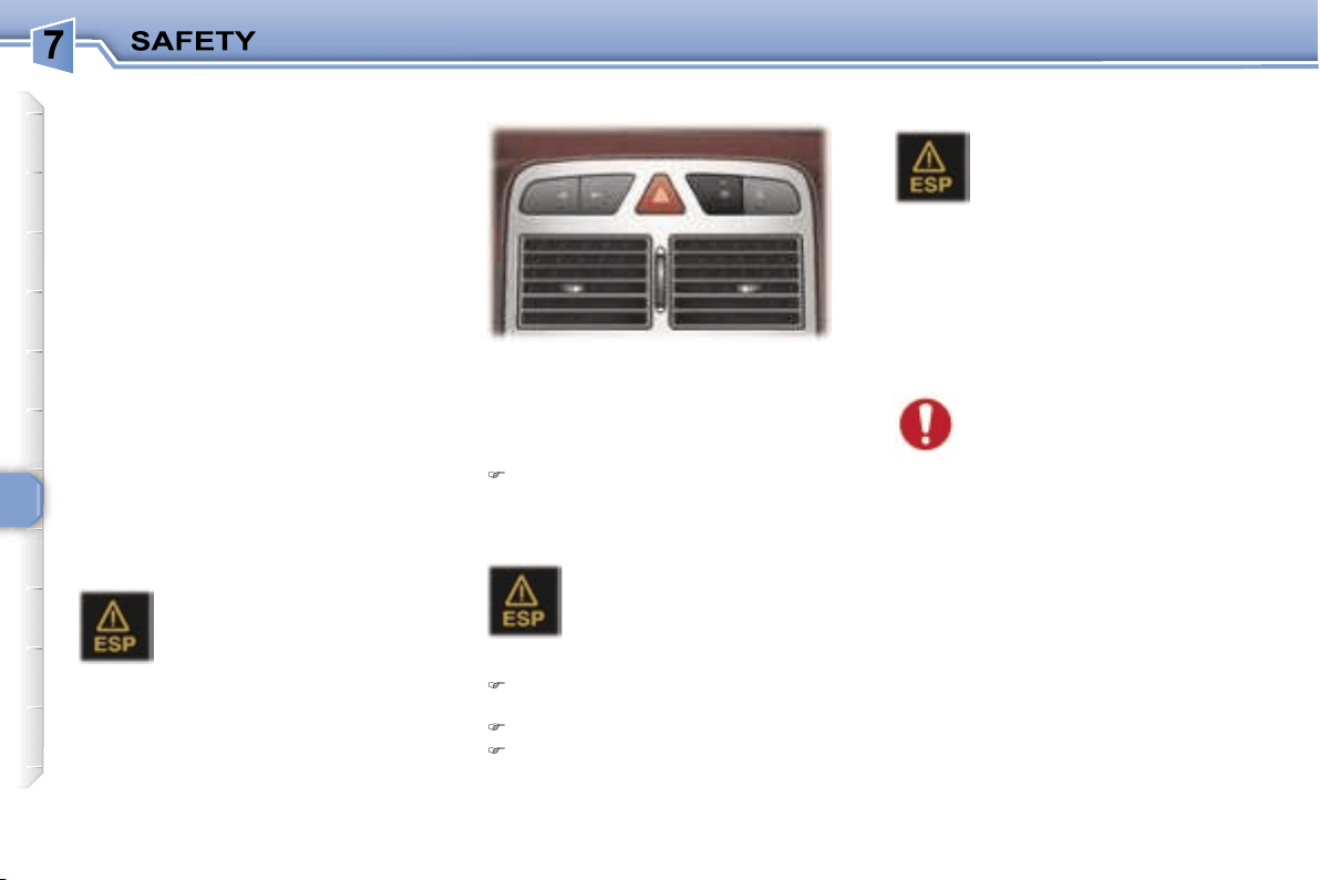
92
TRACTION CONTROL (ASR)
AND DYNAMIC STABILITY
CONTROL (ESP)
These systems are linked and
complement the ABS.
The ASR system optimises drive to
prevent the wheels skidding, by act-
ing on the brakes of the drive wheels
and on the engine. It also allows the
directional stability of the vehicle to
be improved on acceleration.
If there is a variation between the tra-
jectory followed by the vehicle and
that required by the driver, the ESP
system automatically acts on the en-
gine and the brake of one or more
wheels, in order to put the vehicle
back on course, within the limits of
the laws of physics.
In exceptional conditions (starting a
vehicle which is bogged down, stuck
in snow, on soft ground, ...), it may
be advisable to disarm the ASR and
ESP systems, so that the wheels can
move freely and regain grip.
Press the
"ESP OFF"
switch, lo-
cated on the central section of the
fascia.
Operating check
The ESP/ASR systems offer
exceptional safety in normal
driving, but this should not
encourage the driver to take
extra risks or drive at high speed.
The correct functioning of these
systems depends on observation of
the manufacturer’s recommenda-
tions regarding the wheels (tyres
and rims), the braking components,
the electronic components and the
PEUGEOT assembly and operation
procedures.
After an impact, have the systems
checked by a PEUGEOT dealer.
Operation of the ASR and ESP
systems
The switch lights up and
the warning light comes on:
the ASR and ESP systems
are disarmed.
Reactivation
Automatic if the ignition is switched
off.
Automatic above 30 mph (50 km/h).
Manual by pressing the switch
again.
When a malfunction of the
systems occurs, the switch
light flashes and the warn-
ing light comes on, accom-
panied by an audible signal
and a message on the multifunction
display.
Contact a PEUGEOT dealer to have
the systems checked.
The warning light flashes
if the ASR or ESP is acti-
vated.
Disarming
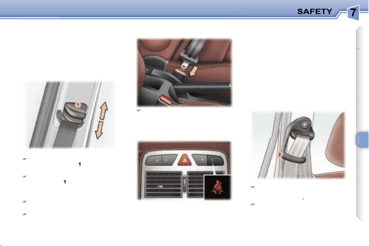
93
To adjust the height in the front:
To lower the attachment point,
squeeze control
1
and slide it
downwards.
To raise the attachment point,
slide control
1
upwards.
Fastening the seat belts
Pull the strap, then insert the
buckle into the stalk.
Check that the seat belt is faste-
ned by pulling the strap.
Unfastening the seat belts
When the ignition is switched on, the
warning light comes on if the driver
and/or the front passenger has not
fastened his seat belt.
for children or people of a short
stature, pass the seat belt under
the strap guide
2
,
for other passengers, pass the
seat belt over the strap guide.
This strap guide prevents the seat
belt from passing over the neck of
these passengers.
SEAT BELTS
Front and 2nd row rear side
seat belts
The front seats are fitted with pre-
tensioners and force limiters while
the rear seats have force limiters
only.
Seat belt unfastened/not fastened
warning light
Press the red button on the stalk
then remove the buckle.
With the engine running and the
doors closed, the light switches off
automatically after 30 seconds.
If a front seat belt is unfastened:
- below 12 mph (20 km/h), the light
comes on constantly,
- above 12 mph (20 km/h) and for
two minutes, the warning light
flashes accompanied by an audible
signal of increasing volume. Once
these two minutes have elapsed,
the warning light remains on until
the driver and/or the front passen-
ger fastens his seat belt.
Routing the 2nd row rear side
seat belt:
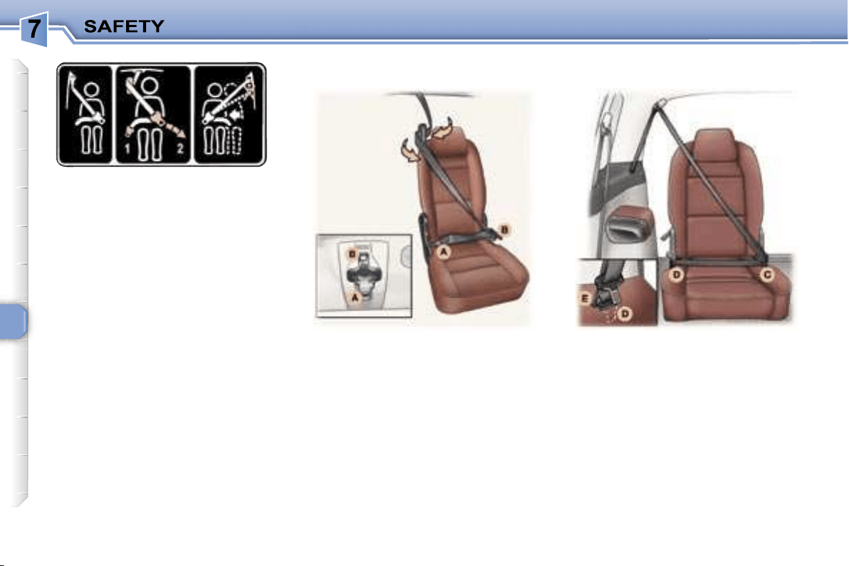
94
- On the left-hand side: in the 3-seat
configuration in the 2nd row, use
the strap guide for people of a short
stature only.
- On the right-hand side: in the re-
aligned side seats configuration, do
not use the strap guide.
Pre-tensioning and force-limiting
seat belts
Safety in the event of a frontal impact
has been improved by the introduc-
tion of pre-tensioning and force-
limiting seat belts. Depending on the
seriousness of the impact, the pre-
tensioning system instantly tightens
the seat belts firmly against the body
of the occupant.
The pre-tensioning seat belts are
armed when the ignition is on.
The force-limiting device reduces the
pressure of the seat belt against the
occupant’s body in the event of an
accident.
The 2nd row rear centre seat has a
three-point inertia reel seat belt in-
corporated in the centre of the roof.
Pass buckle
A
, then buckle
B
, into
the strap guide working from the in-
side to the outside of the seat.
Insert buckle
A
into its stalk (right),
then buckle
B
into its stalk (left).
To remove the seat belt, proceed in
the reverse order, then move buck-
le
B
to the magnet of the roof fixing
point.
The 3rd row rear seats are fitted
with two three-point inertia reel seat
belts.
To put on the seat belt, insert buckle
C
then buckle
D
into their respective
stalks.
To remove the seat belt, proceed in
the reverse order, then move buckle
D
to the location
E
provided.
2nd row rear centre seat belt
3rd row rear seat belts
95
Wherever you are seated in
the vehicle, always fasten
your seat belt, even for short
journeys.
In order to be effective, a seat belt:
- must be tightened as close to the
body as possible,
- must restrain one adult only,
- must not bear any trace of cuts or
fraying,
- must be pulled in front of you with a
smooth movement, checking that it
does not twist,
- must not be transformed or modified
to avoid altering its performance.
In accordance with current safety
regulations, all repairs and checks
must be carried out by a PEUGEOT
dealer who guarantees that the work
is carried out correctly.
Have your seat belts checked regu-
larly by a PEUGEOT dealer and par-
ticularly if the straps show signs of
damage.
Clean the seat belt straps with soapy
water or a textile cleaning product,
sold by PEUGEOT dealers.
After folding or moving a seat or rear
bench seat, ensure that the seat belt
is positioned and rolled up correctly.
* According to model.
Do not invert the seat belt buckles as
they will not fulfil their role fully.
If the seats have armrests*, the lap
part of the seat belt must always
pass under the armrest.
The seat belts are fitted with an in-
ertia reel permitting automatic adjust-
ment of the length of the strap to your
size. The seat belt is stored automat-
ically when not in use.
Before and after use, ensure that the
seat belt is rolled up correctly.
The lower part of the strap must be
positioned as low as possible on the
pelvis.
The upper part must be positioned in
the hollow of the shoulder.
The inertia reels are fitted with an au-
tomatic locking device which comes
into operation in the event of a colli-
sion or emergency braking. You can
release the device by pulling rapidly
on the strap and releasing it.
Recommendations for children:
- use a suitable child seat if the pas-
senger is less than 12 years old or
shorter than one metre fifty,
- do not use the strap-guide* when a
child seat is installed.
- never use the same seat belt to se-
cure more than one person,
- never allow a child to travel on your
lap.
Depending on the nature and se-
riousness of the impacts
, the pre-
tensioning device may be triggered
before and independently of the air
bags.
In all cases, the air bag warning light
comes on.
Following an impact, have the seat
belts system checked, and if neces-
sary replaced, by a PEUGEOT dealer.
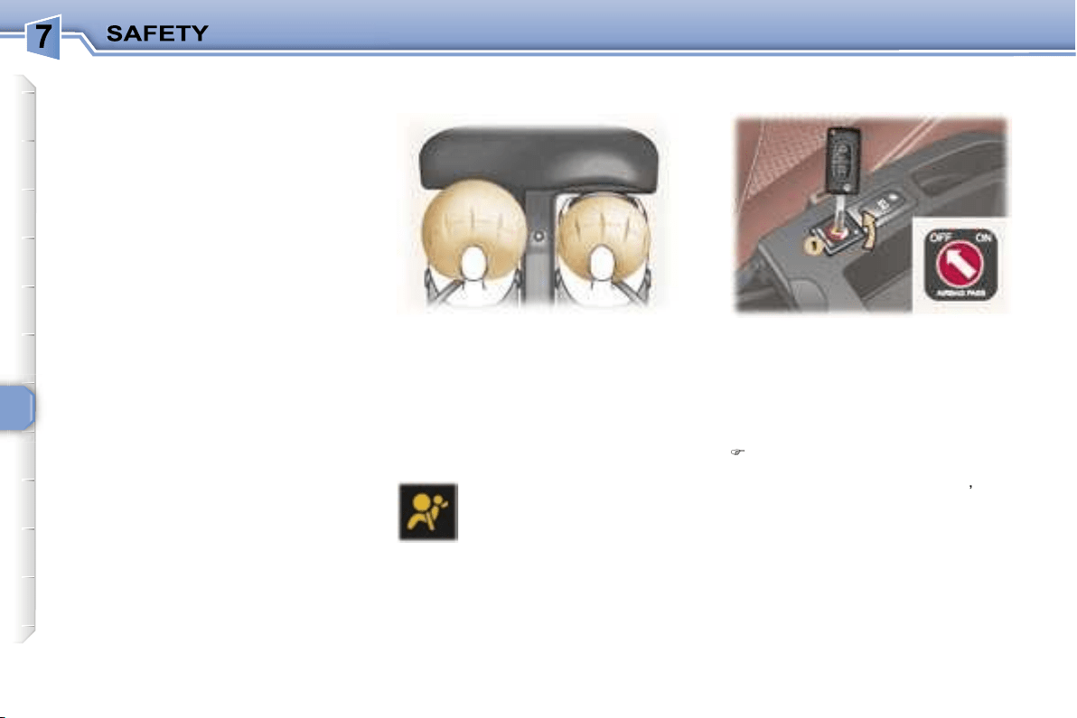
96
AIR BAGS
The air bags have been designed to
maximise the safety of the occupants
in the event of serious collisions; they
work in conjunction with the force
limiting seat belts.
In the event of a serious collision, the
electronic detectors record and ana-
lyse any abrupt deceleration of the
vehicle: if the triggering threshold is
reached, the air bags inflate instantly
and protect the occupants of the ve-
hicle.
Immediately after the impact, the air
bags deflate rapidly, so that they do
not hinder the visibility of the occu-
pants nor their possible exit from the
vehicle.
The air bags will not be deployed in
collisions which are not serious, for
which the seat belt is sufficient to
provide maximum protection. The
seriousness of the collision depends
on the nature of the obstacle and the
speed of the vehicle at the moment
of impact.
Air bags only operate when the ig-
nition is switched on.
Note:
the gas escaping from the air
bags can be a minor irritant.
These are folded in the centre of the
steering wheel for the driver and in
the fascia for the front passenger.
They are deployed simultaneously,
except in cases where the air bag is
disarmed.
To ensure the safety of your child,
it is essential to disarm the pas-
senger air bag when you install a
rear-facing child seat on the front
passenger seat. Otherwise, the
child would risk being seriously
injured or killed if the air bag were
to inflate.
With the ignition switched off
,
insert the key into the passenger
air bag disarming switch
1
,
turn
it to the
"OFF"
position, then re-
move the key keeping the switch
in this position.
If this warning light comes
on, accompanied by a buzz-
er and a message on the
multifunction display,
con-
tact a PEUGEOT dealer to
have the system checked.
Front air bag malfunction
* According to country.
Disarming the passenger
air bag*
FRONT AIR BAGS

97
In the
"OFF"
position, the passen-
ger air bag will not be triggered in the
event of an impact.
As soon as the child seat is removed,
turn the air bag switch to the
"ON"
position to re-activate the air bag and
thus ensure the safety of your pas-
senger in the event of an impact.
SIDE AIR BAGS* AND
CURTAIN AIR BAGS*
If the passenger air bag dis-
arming warning light flashes,
contact a PEUGEOT dealer.
In the event of permanent lighting
of the two air bag warning lights, do
not install a rear facing child seat.
Contact a PEUGEOT dealer.
With the ignition on, this is
confirmed by illumination of
this warning light which in-
dicates that the passenger
air bag is disarmed (switch
in the
"OFF"
position).
The warning light is lit throughout the
duration of disarming.
If this indicator light comes
on, accompanied by an au-
dible signal and a message
on the multi-function dis-
play, contact a PEUGEOT
dealer to have the system
checked.
* According to country.
Air bag fault
Disarming check
The side air bags are incorporated
into the front seat backs on the door
side.
The curtain air bags are incorporated
into the door pillars and the upper
part of the passenger compartment.
They are deployed independently of
each other depending on which side
the collision occurs.
98
For the front, side* and
curtain* air bags to be fully
effective, observe the fol-
lowing safety rules:
• Wear a correctly adjusted seat belt.
• Sit in a normal upright position.
• Do not leave anything between the
occupants and the air bags (child,
animal, object...).
This could hamper the operation
of the air bags or injure the occu-
pants.
• All work on the air bag systems is
strictly prohibited unless it is car-
ried out by qualified personnel of
the PEUGEOT network.
• After an accident or if the vehicle
has been stolen or broken into,
have the air bag systems checked.
Front air bags
• Do not drive holding the steering
wheel by its spokes or resting your
hands on the centre part of the
wheel.
• Passengers must not place their
feet on the fascia.
• Smoke as little as possible; deploy-
ment of the air bags can cause
burns or the risk of injury from a
cigarette or pipe.
• Never remove or pierce the steer-
ing wheel or hit it violently.
Curtain air bags*
• Do not fix or glue anything to the
pillars or the roof. This could cause
injury to the head when the curtain
air bag inflates.
• Do not remove the bolts from the
grab handles installed on the roof,
they play a part in securing the
curtain air bags.
* According to country.
Side air bags*
• Only put approved covers on
the front seats. Contact your
PEUGEOT dealer.
• Do not fix or glue anything to the
front seat backs. This could cause
injury to the chest or arms when the
side air bag inflates.
• Do not sit with the upper part of the
body any nearer to the door than
necessary.
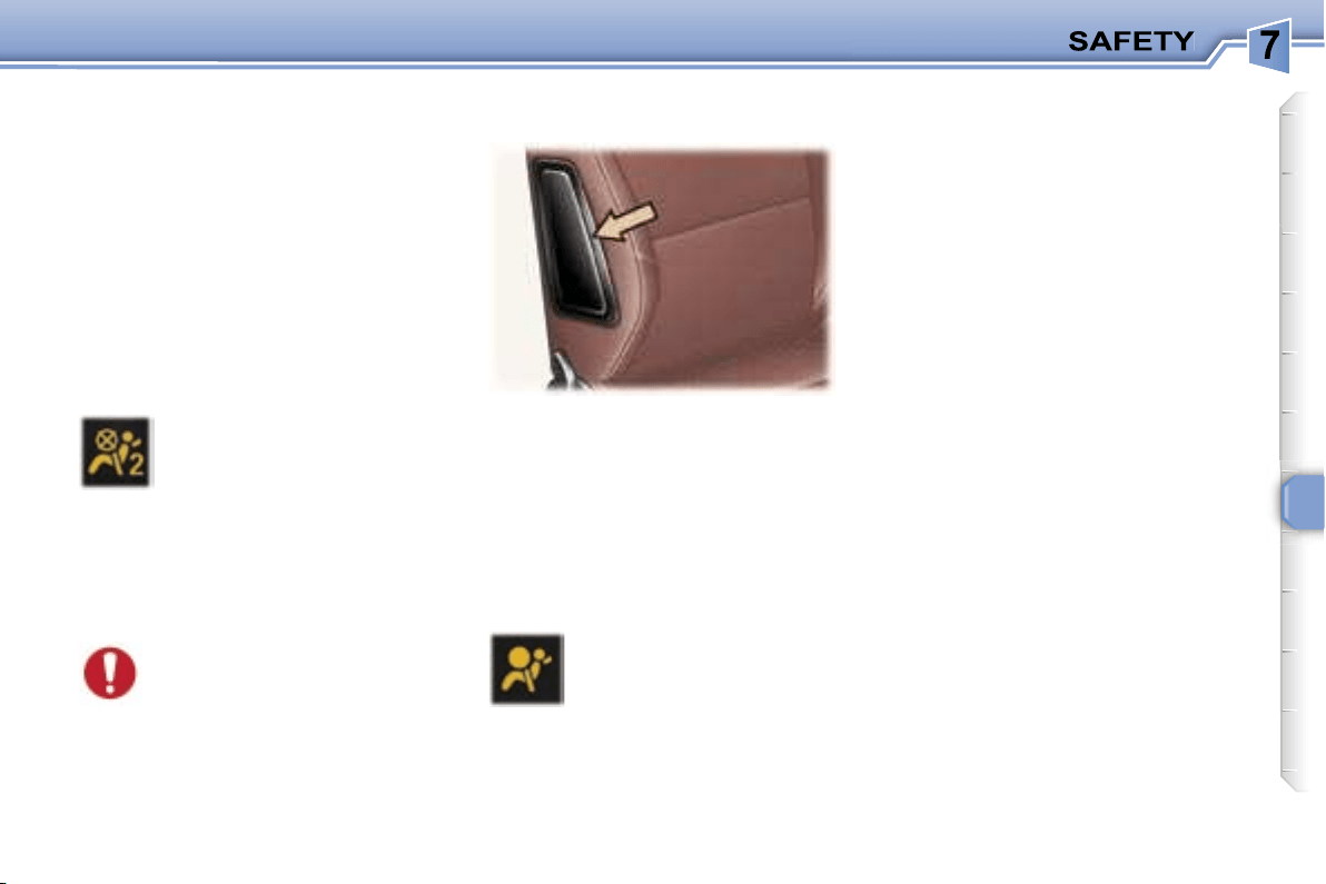
97
In the
"OFF"
position, the passen-
ger air bag will not be triggered in the
event of an impact.
As soon as the child seat is removed,
turn the air bag switch to the
"ON"
position to re-activate the air bag and
thus ensure the safety of your pas-
senger in the event of an impact.
SIDE AIR BAGS* AND
CURTAIN AIR BAGS*
If the passenger air bag dis-
arming warning light flashes,
contact a PEUGEOT dealer.
In the event of permanent lighting
of the two air bag warning lights, do
not install a rear facing child seat.
Contact a PEUGEOT dealer.
With the ignition on, this is
confirmed by illumination of
this warning light which in-
dicates that the passenger
air bag is disarmed (switch
in the
"OFF"
position).
The warning light is lit throughout the
duration of disarming.
If this indicator light comes
on, accompanied by an au-
dible signal and a message
on the multi-function dis-
play, contact a PEUGEOT
dealer to have the system
checked.
* According to country.
Air bag fault
Disarming check
The side air bags are incorporated
into the front seat backs on the door
side.
The curtain air bags are incorporated
into the door pillars and the upper
part of the passenger compartment.
They are deployed independently of
each other depending on which side
the collision occurs.

98
For the front, side* and
curtain* air bags to be fully
effective, observe the fol-
lowing safety rules:
• Wear a correctly adjusted seat belt.
• Sit in a normal upright position.
• Do not leave anything between the
occupants and the air bags (child,
animal, object...).
This could hamper the operation
of the air bags or injure the occu-
pants.
• All work on the air bag systems is
strictly prohibited unless it is car-
ried out by qualified personnel of
the PEUGEOT network.
• After an accident or if the vehicle
has been stolen or broken into,
have the air bag systems checked.
Front air bags
• Do not drive holding the steering
wheel by its spokes or resting your
hands on the centre part of the
wheel.
• Passengers must not place their
feet on the fascia.
• Smoke as little as possible; deploy-
ment of the air bags can cause
burns or the risk of injury from a
cigarette or pipe.
• Never remove or pierce the steer-
ing wheel or hit it violently.
Curtain air bags*
• Do not fix or glue anything to the
pillars or the roof. This could cause
injury to the head when the curtain
air bag inflates.
• Do not remove the bolts from the
grab handles installed on the roof,
they play a part in securing the
curtain air bags.
* According to country.
Side air bags*
• Only put approved covers on
the front seats. Contact your
PEUGEOT dealer.
• Do not fix or glue anything to the
front seat backs. This could cause
injury to the chest or arms when the
side air bag inflates.
• Do not sit with the upper part of the
body any nearer to the door than
necessary.
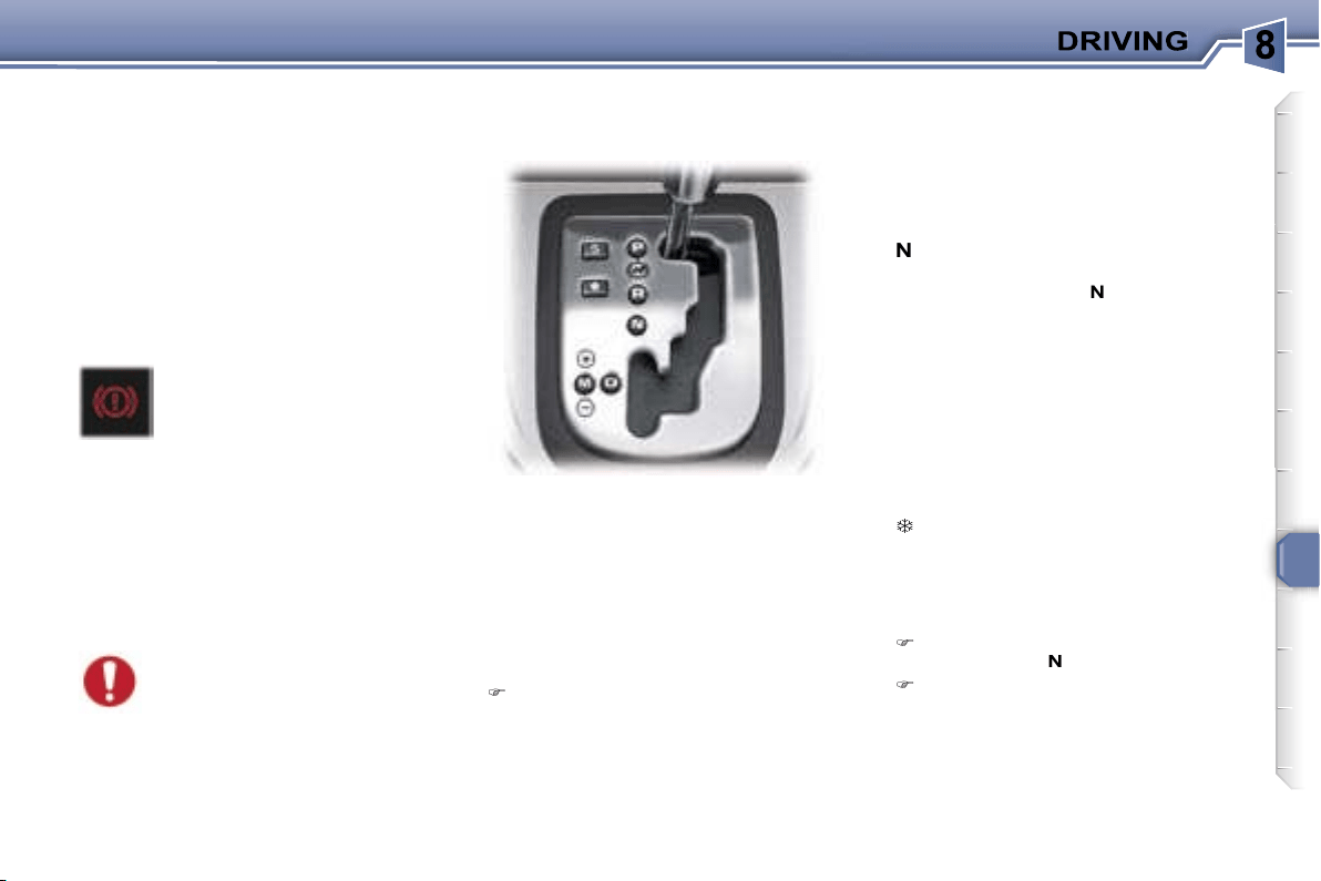
99
HANDBRAKE
Applying
Pull the handbrake to immobilise
your vehicle.
When the vehicle is being
driven, illumination of this
warning light and of the
STOP
warning light, ac-
companied by an audible
signal and a message on the multi-
function display, indicates that the
handbrake is still on or has not been
properly released.
When parking on a slope,
direct your wheels towards
the pavement and pull the
handbrake.
Releasing
Pull on the handle and press the
button to release the handbrake.
The four or six speed
automatic
gearbox offers a choice between
the comfort of
integral automatic
operation, enhanced by a
sport
and
a snow programme, or
manual gear
changing.
P
ark: to
immobilise
the vehicle or
start the engine
, with the handbrake
on or off.
R
everse: to
reverse
(select this
position with the vehicle stationary,
engine at idle).
N
eutral: to
start the engine
and to
park
, with the handbrake on.
Note:
if position
N
is engaged
inadvertently while driving, allow
the engine to return to idle before
engaging position
D
to accelerate.
D
rive: for
driving
in automatic
mode.
M
anual: to
select
the gears.
S
: sport programme.
: snow programme.
Gear selection gate
Move the lever in the gate to
select a position.
The indicator light for the selec-
tion is displayed on the instrument
panel display.
Starting the engine
with the handbrake applied, select
position
P
or
N
in the gate,
turn the ignition key to the
Starting
position.
Otherwise, you are warned by an
audible signal and a message on the
multifunction display.
"PORSCHE TIPTRONIC
SYSTEM" AUTOMATIC
GEARBOX
100
Moving off
With the engine running, to move off
from position
P
:
it is essential to press the brake
pedal,
release the handbrake,
select position
R
,
D
or
M
, then
gradually release the pressure
on the brake pedal; the vehicle
moves off immediately.
You can also move off from position
N
.
When the engine is at idle,
brakes not applied, if posi-
tion
R
,
D
or
M
is selected the
vehicle moves even without
the accelerator being pressed.
For this reason,
do not leave
children unsupervised inside the
vehicle, with the engine running
.
If the lever is not in position
P
, an
audible signal is heard and a mes-
sage appears when the driver’s door
is opened or approximately 45 sec-
onds after the ignition is switched
off. Move the lever to
P
. The audible
signal stops and the message disap-
pears.
When maintenance opera-
tions need to be carried out
with the engine running, ap-
ply the handbrake and select
position
P
.
Never select position
N
when
the vehicle is moving.
Never select positions
P
or
R
unless the vehicle is
stationary.
Never change between positions to
optimise braking on a slippery sur-
face.
Sport and snow programmes
In addition to the auto-adaptive
programme, there are two special
programmes.
The programme is displayed on the
instrument panel screen.
Automatic operation
Automatic
changing of the four or
six gears:
select position
D
in the gate.
The gearbox automatically adapts
the gear in relation to the style of
driving, the road profile and the
vehicle load.
The gearbox is then operating in
auto-adaptive mode, without any
action on your part.
For immediate maximum accelera-
tion without touching the gear lever,
press the accelerator pedal down as
far as it will go (kickdown). The gear-
box will automatically change down
or maintain the gear selected until
maximum engine speed is reached.
When braking, the gearbox will au-
tomatically change down in order to
provide efficient engine braking.
If you take your foot off the accel-
erator suddenly, the gearbox will not
change to a higher gear for reasons
of safety.
Sport programme
Press button
S
once the engine
has been started.
The gearbox automatically favours
sporty driving and more dynamic
acceleration.
Snow programme
This programme improves starting
and drive when traction is poor.
Press button
once the engine
has been started.
The gearbox adapts to driving on
slippery roads.
Note:
you can return to the auto-
adaptive programme at any time.
Press button
S
or
again to switch
off the programme you are in.
101
Manual operation
Manual
changing of the four or six
gears:
select position
M
in the gate,
push the lever to the
+
sign to
change to a higher gear,
pull the lever to the
-
sign to chan-
ge to a lower gear.
You can change from position
D
(driving in automatic mode) to posi-
tion
M
(driving in manual mode) at
any time.
Invalid value during manual
operation
Notes
It is only possible to change from one
gear to another if the vehicle speed
and engine speed permit. If they do
not, the vehicle will operate tempo-
rarily in automatic mode.
In the event of under-revving or over-
revving, the gear selected flashes for
a few seconds, then the actual gear
engaged is displayed.
When the vehicle is stationary or
moving very slowly, the gearbox au-
tomatically selects gear
M1
.
Programme
S
(sport) and
(snow)
do not operate in manual mode.
Operating abnormality
Any operating abnormality
is indicated by the display-
ing of this warning light, an
audible signal and a mes-
sage on the multi-function
display.
In this situation the gearbox oper-
ates in downgrade mode (locked in
3
rd
ates in downgrade mode (locked in
ates in downgrade mode (locked in
gear). You may feel a substantial
knock when changing from
P
to
R
and from
N
to
R
(this will not cause
any damage to the gearbox).
Do not exceed 60 mph (100 km/h),
keeping within the limit of local speed
restrictions.
Contact a PEUGEOT dealer as soon
as possible.
If the battery is flat and the
lever is in position
P
, it will be
impossible to change to an-
other position.
Above all, do not force the le-
ver as there is a risk of damage to the
automatic gearbox.
This is displayed if a gear
is not engaged correctly
(selector between two posi-
tions).
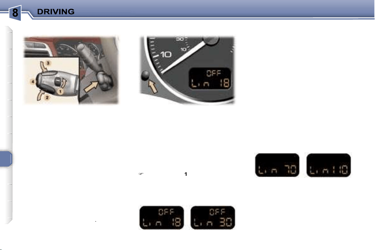
102
This speed limiter, of the new gener-
ation, has a display on the instrument
panel to indicate the programmed
speed.
It prevents exceeding of the vehicle
speed programmed by the driver.
When the programmed speed is
reached, pressing the accelerator
pedal no longer has any effect.
The limiter operates with a pro-
grammed speed of at least 18 mph
(30 km/h); it remains active regard-
less of any action on the brake and
clutch pedals.
The operating actions must be
carried out:
- when stationary, with the engine
running,
or
- with the vehicle moving
.
When the speed limiter function is
active, pressing this button displays
the distance recorders.
After a few seconds or when this but-
ton is pressed again, the display re-
turns to the speed limiter function.
Storing a speed
A speed can be stored without acti-
vating the limiter.
Press buttons
2
and
3
briefly to de-
crease or increase by 1 mph (1 km/h).
An extended press decreases or in-
creases by 5 mph (5 km/h).
A maintained press decreases or
increases the programmed speed in
steps of 5 mph (5 km/h).
Selecting the function
Place the dial
1
in the
LIMIT
posi-
tion. The limiter is not yet active.
By default, the display indicates:
Activating/deactivating the limiter
Pressing button
4
once activates the
limiter, pressing the button again de-
activates it.
When the limiter is active, the display
indicates (e.g. at 70 mph (110 km/h)):
* According to country.
Instrument panel displaySPEED LIMITER*
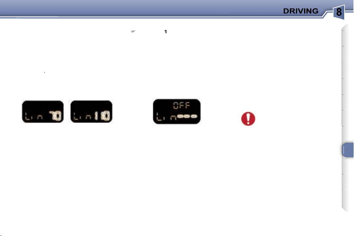
103
Note:
the speed also flashes when
the limiter cannot prevent the vehi-
cle from exceeding the programmed
speed (on a steep descent, in the
event of sharp acceleration).
To reactivate the limiter, release the
accelerator to slow down to a speed
below the programmed speed.
Switching the function off
Place dial
1
in position
0
or switch
off the ignition to switch the sys-
tem off. The last programmed
speed remains in the memory.
Operating fault
In the event of a limiter malfunction,
the programmed speed is cleared,
the dashes flash for a few seconds:
Contact a PEUGEOT dealer to have
the system checked.
In the event of a steep de-
scent or sharp acceleration,
the speed limiter will not be
able to prevent the vehicle
from exceeding the programmed
speed.
In any event, the speed limiter cannot
replace the need to observe speed
limits, nor can it replace the need for
vigilance and responsibility on the
part of the driver.
To prevent the mat from becoming
caught under the pedals:
- ensure that the mat is positioned
correctly.
- never fit one mat on top of another.
Exceeding the programmed
speed
In exceptional circumstances, use
this mode to exceed the programmed
speed.
Pressing the accelerator in order to
exceed the programmed speed will
have no effect unless you press the
pedal
firmly
beyond the
point of re-
sistance
.
The limiter is deactivated temporarily
and the speed displayed on the instru-
ment panel flashes (e.g. at 70 mph
(110 km/h)):
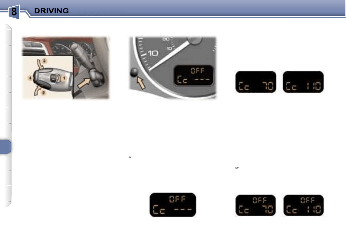
104
This cruise control, of the new genera-
tion, is linked with the speed limiter. It
has a display on the instrument panel
to indicate the memorised reference
speed.
It enables the vehicle to maintain a
steady speed programmed by the
driver.
In order for it to be memorised or ac-
tivated, the vehicle speed must be
greater than 25 mph (40 km/h) with
at least fourth gear engaged for vehi-
cles fitted with a manual gearbox.
On vehicles fitted with an automatic
gearbox, the lever must be in posi-
tion
D
, or in at least second gear in
sequential mode.
When the cruise control function is
activated, pressing this button ena-
bles you to display the distance re-
corders.
After a few seconds or when this button
is pressed again, the display returns to
the cruise control function.
First activation/memorising a
reference speed
As soon as you reach the chosen
speed, press button
2
or
3
. This me-
morises the speed and the display in-
dicates (e.g. at 70 mph (110 km/h)):
Selecting the function
Place switch
1
in the
CRUISE
po-
sition. The cruise control is not yet
active and no speed has been me-
morised. The display indicates:
Note:
It is possible to accelerate
and drive momentarily at a speed
greater than the memorised speed.
The value memorised flashes. When
the accelerator pedal is released, the
vehicle will return to the memorised
speed.
Cancelling the cruise control
If you wish to cancel the cruise
control:
Press button
4
or the brake or
clutch pedal.
The display indicates (e.g. at 70 mph
(110 km/h)):
* According to country.
CRUISE CONTROL* Instrument panel display

105
Cancelling the memorised
reference speed
When the vehicle becomes statio-
nary, after switching off the ignition,
the system no longer memorises a
speed.
When changing the memo-
rised reference speed by
means of a maintained press,
pay attention as the speed
can increase or decrease rapidly.
Do not use the cruise control on slip-
pery roads or in heavy traffic.
In the event of a steep slope, the
cruise control cannot prevent the
vehicle from exceeding the pro-
grammed speed.
In any event, the cruise control can-
not replace the need to comply with
speed limits, nor can it replace the
need for vigilance and responsibility
on the part of the driver.
To prevent the mat from becoming
caught under the pedals:
- ensure that the mat is positioned
correctly.
- never fit one mat on top of another.
Reactivating the cruise control
After cancellation of the cruise con-
trol,
press
button
4
. Your vehicle will
return to the last memorised speed.
The display indicates (e.g. at 70 mph
(110 km/h)):
Changing the memorised
reference speed
To memorise a speed higher than the
previous one, there are two options:
Without using the accelerator:
press button
3
;
A brief press increases by 1 mph
(1 km/h).
An extended press increases by
5 mph (5 km/h).
A maintained press increases in
steps of 5 mph (5 km/h).
Using the accelerator:
exceed the memorised speed un-
til the required speed is reached,
press button
2
or
3
.
Switching the function off
Place dial
1
in position
0
to switch
the system off.
Operating fault
In the event of a cruise control mal-
function, the memorised speed is
erased, the dashes flash for a few
seconds:
To memorise a speed lower than the
previous one:
press button
2
;
A brief press decreases by 1 mph (1 km/h).
An extended press decreases by 5 mph
(5 km/h).
A maintained press decreases in steps
of 5 mph (5 km/h).
Contact a PEUGEOT dealer to have
the system checked.
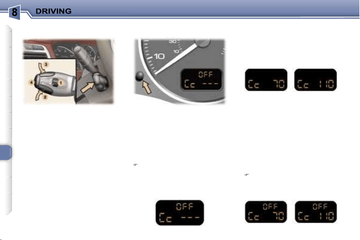
106
This cruise control has a display on
the instrument panel to indicate the
memorised reference speed.
It enables the vehicle to maintain a
steady speed programmed by the
driver.
In order for it to be memorised or ac-
tivated, the vehicle speed must be
greater than 25 mph (40 km/h) with
at least fourth gear engaged for vehi-
cles fitted with a manual gearbox.
On vehicles fitted with an automatic
gearbox, the lever must be in posi-
tion
D
or at least second gear must
be engaged in sequential driving
mode.
When the cruise control function is
activated, pressing this button ena-
bles you to display the distance re-
corder.
After a few seconds or when this but-
ton is pressed again, the display re-
turns to the cruise control function.
First activation/memorising a
reference speed
As soon as you reach the chosen
speed, press button
2
or
3
. This me-
morises the speed and the display in-
dicates (e.g. at 70 mph (110 km/h)):
Selecting the function
Place switch
1
in the
ON
position.
The cruise control is not yet active
and no speed has been memo-
rised. The display indicates:
Note:
It is possible to accelerate
and drive momentarily at a speed
greater than the memorised speed.
The value memorised flashes. When
the accelerator pedal is released, the
vehicle will return to the memorised
speed.
Cancelling the cruise control
If you wish to cancel the cruise
control:
Press button
4
or the brake or
clutch pedal.
The display indicates (e.g. at 70 mph
(110 km/h)):
* According to country.
Instrument panel displayCRUISE CONTROL*
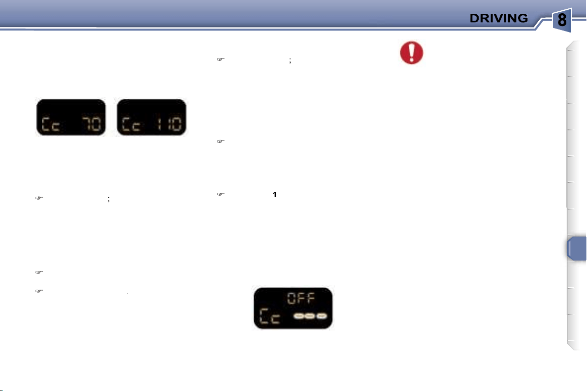
107
Reactivating the cruise control
After cancellation of the cruise con-
trol,
press
button
4
. Your vehicle will
return to the last memorised speed.
The display indicates (e.g. at 70 mph
(110 km/h)):
Cancelling the memorised
reference speed
When the vehicle is stationary, af-
ter the ignition has been switched
off, the system no longer stores
any speed.
Changing the memorised
reference speed
To memorise a speed higher than the
previous one, there are two options:
Without using the accelerator:
press button
3
;
A brief press increases by 1 mph
(1 km/h).
An extended press increases by
5 mph (5 km/h).
A maintained press increases in
steps of 5 mph (5 km/h).
Using the accelerator:
exceed the memorised speed un-
til the required speed is reached,
press button
2
or
3
.
Switching the function off
Place dial
1
in the
OFF
position to
switch the system off.
Operating fault
In the event of a cruise control mal-
function, the memorised speed is
erased, the dashes flash for a few
seconds:
When changing the memo-
rised reference speed by
means of a maintained press,
pay attention as the speed
can increase or decrease rapidly.
Do not use the cruise control on slip-
pery roads or in heavy traffic.
In the event of a steep slope, the
cruise control cannot prevent the
vehicle from exceeding the pro-
grammed speed.
In any event, the cruise control can-
not replace the need to observe the
speed limits, nor can it replace the
need for vigilance and responsibility
on the part of the driver.
To prevent the mat from becoming
caught under the pedals:
- ensure that the mat is positioned
correctly.
- never fit one mat on top of another.
To memorise a speed lower than the
previous one:
press button
2
;
A brief press decreases by 1 mph (1 km/h).
An extended press decreases by 5 mph
(5 km/h).
A maintained press decreases in
steps of 5 mph (5 km/h).
Contact a PEUGEOT dealer to have
the system checked.
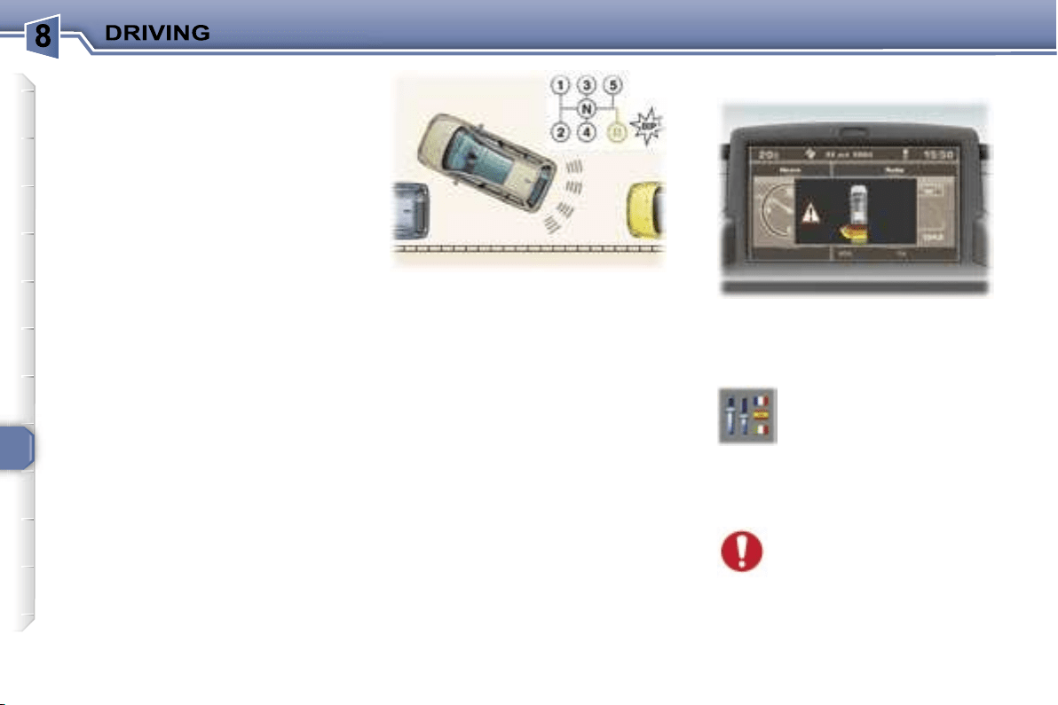
108
VISUAL AND AUDIBLE REAR
PARKING ASSISTANCE
This system consists of four proximity
sensors, located in the rear bumper.
This detects any obstacle (person,
vehicle, tree, gate, etc.) behind the
vehicle. Nevertheless, it cannot de-
tect obstacles located just below the
bumper.
An object, such as a stake, a road-
works cone or any other similar object
may be detected at the beginning of
the manoeuvre, but may no longer
be detected when the vehicle comes
close to it.
Note:
this function will be disarmed
automatically when the vehicle is
towing a trailer or when a bicycle car-
rier is fitted (vehicle fitted with towing
attachment or bicycle carrier
recom-
mended by PEUGEOT).
In bad or wintry weather, ensure that
the sensors are not covered with
mud, frost or snow. When reverse
gear is engaged, an audible signal
(long bleep) indicates that the sen-
sors may be dirty.
The proximity information is given
by:
- an audible signal, which becomes
more rapid as the vehicle ap-
proaches the obstacle,
- a graphic on the multifunction dis-
play, with blocks which become
progressively closer to the vehicle.
Depending on the multifunction dis-
play, the audible signal is transmitted
by a buzzer or by the rear speakers
which transmit:
- on the right if an obstacle is detect-
ed on the right,
- on the left if an obstacle is detected
on the left,
- on the right and on the left if an
obstacle is detected in the centre.
When the distance between the rear
of the vehicle and the obstacle is
less than approximately thirty centi-
metres, the audible signal becomes
continuous and the "Danger" symbol
appears depending on the multifunc-
tion display.
Change to neutral, the system is
again inactive.
If there is an operating fault,
when reverse gear is en-
gaged, the service warning
light comes on, accompanied
by an audible signal (short bleep)
and a message on the multifunction
display.
Contact a PEUGEOT dealer.
Activation/Deactivation
Activation
The system is activated as soon as
reverse gear is engaged.
This is accompanied by an audible
signal and displaying of the vehicle,
depending on the multifunction dis-
play.
The system can be activat-
ed or deactivated from the
multifunction display con-
figuration menu.
The activation and deacti-
vation of the system are memorised
when the engine is switched off.
Switching the system off
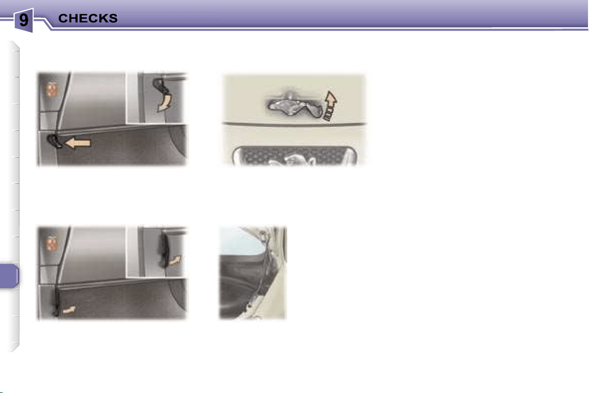
110
Push the handle on the left-hand side
under the fascia.
Lift the catch and raise the bonnet.
Bonnet strut
RUNNING OUT OF FUEL
(DIESEL)
If you should run out of fuel, it is nec-
essary to re-prime the circuit.
The repriming pump, the degas
screw and the transparent pipe are
located under the bonnet (see corre-
sponding drawing):
1.6 litre HDI 16V engine
- fill the fuel tank with at least five li-
tres of diesel,
- unclip the style cover to access the
repriming pump,
- squeeze and release the manual
repriming pump until fuel appears
in the transparent pipe with the
green connector,
- operate the starter until the engine
starts.
2 litre HDI 16V engine
- fill the fuel tank with at least five li-
tres of diesel,
- unclip the style cover to access the
repriming pump,
- unscrew the degas screw,
- squeeze and release the manual
repriming pump until diesel is seen
escaping via the degas screw,
- retighten the degas screw,
- operate the starter until the engine
starts.
Tilt the handle on the left-hand side
under the fascia to the right*.
OPENING THE BONNET
From outside
or
* During the year.
Secure the strut
to hold the bonnet
open.
Before closing the
bonnet, replace
the strut in its
housing.
To close
Lower the bonnet and release it at
the end of its travel.
Check that the bonnet is properly locked.
From inside
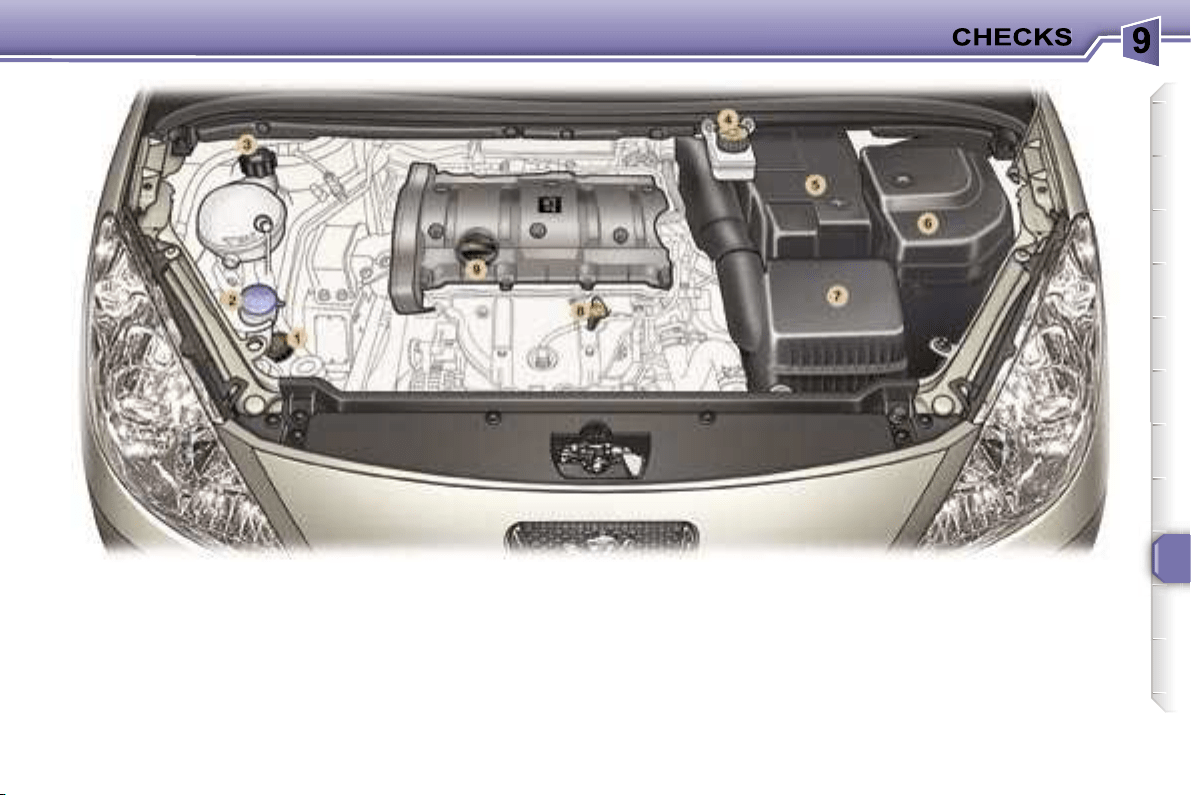
111
1.
Power steering reservoir.
2.
Windscreen/headlamp wash
reservoir.
3.
Coolant reservoir.
4.
Brake fluid reservoir.
5.
Battery.
6.
Fuse box.
7.
Air filter.
8.
Dipstick.
9.
Engine oil reservoir.
1.6 LITRE 16V PETROL ENGINE
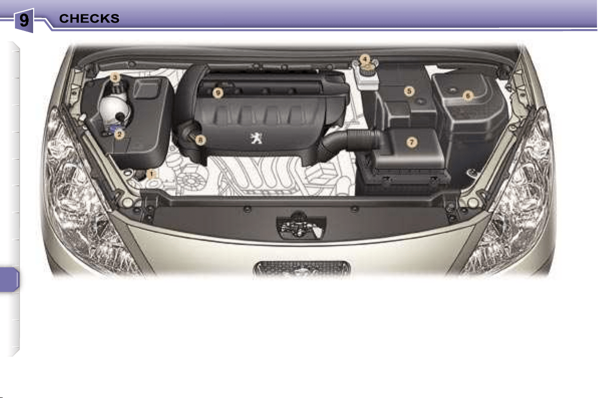
112
1.
Power steering reservoir.
2.
Windscreen/headlamp wash
reservoir.
3.
Coolant reservoir.
4.
Brake fluid reservoir.
5.
Battery.
6.
Fuse box.
7.
Air filter.
8.
Dipstick.
9.
Engine oil reservoir.
2 LITRE 16V PETROL ENGINE
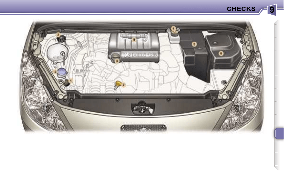
113
1.
Power steering reservoir.
2.
Windscreen/headlamp wash
reservoir.
3.
Coolant reservoir.
4.
Brake fluid reservoir.
5.
Battery.
6.
Fuse box.
7.
Dipstick.
8.
Engine oil reservoir.
9.
Priming pump.
1.6 LITRE 16V TURBO DIESEL HDI ENGINE (90 bhp/110 bhp)
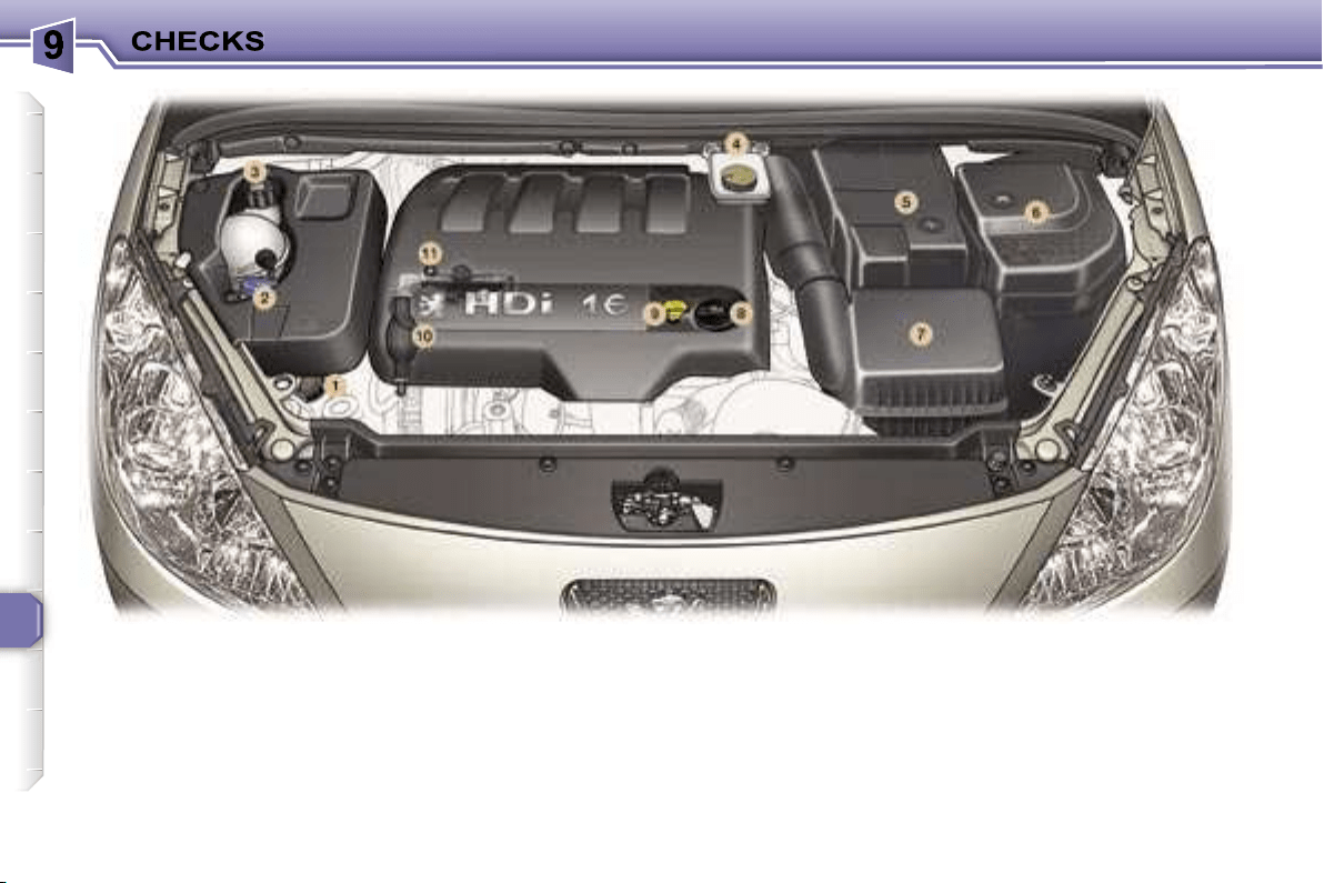
114
1.
Power steering reservoir.
2.
Windscreen/headlamp wash
reservoir.
3.
Coolant reservoir.
4.
Brake fluid reservoir.
5.
Battery.
6.
Fuse box.
7.
Air filter.
8.
Engine oil reservoir.
9.
Dipstick.
10.
Priming pump.
11.
Degas screw.
2 LITRE 16V TURBO DIESEL HDI ENGINE (136 bhp)
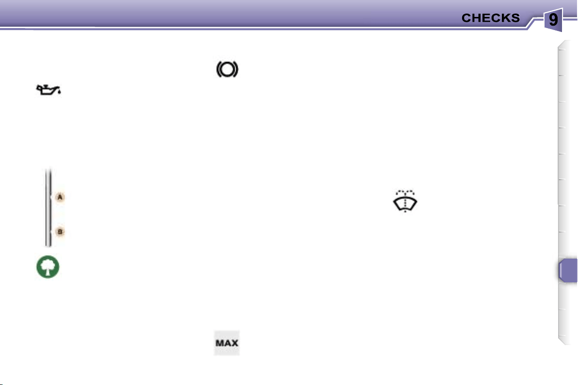
115
CHECKING THE LEVELS
There are two marks on
the dipstick:
A
= maximum
Never fill past this mark.
B
= minimum
To maintain the reliability of
engines and emission control
systems, the use of additives
in engine oil is prohibited.
Viscosity selection
In all cases, the oil selected must
meet the manufacturer’s require-
ments.
Note:
the coolant does not need to
be changed.
Dipstick
Cooling system
Use the fluid recommended by the
manufacturer.
When the engine is warm, the tem-
perature of the coolant is controlled
by the engine fan. This fan can oper-
ate with the ignition off.
In the case of vehicles fitted with
a particle emission filter, the fan
can operate after the vehicle has
stopped, even when the engine is
cold.
In addition, as the cooling system is
pressurised, wait for at least one hour
after the engine has stopped before
carrying out any work.
Slacken the cap by two turns to re-
lease the pressure to prevent any
risk of scalding. When the pressure
has dropped, remove the cap and
top up the level.
Windscreen and headlamp
wash level
Diesel additive level (Diesel
with particle emission filter)
If the service warning light comes on,
accompanied by a message and an
audible signal, this indicates a low
diesel additive level.
This additive must be topped up.
Contact a PEUGEOT dealer as soon
as possible.
* According to engine.
Brake fluid level
Oil level
Oil change
According to the information given in
the servicing booklet.
The level should always be
above the MIN mark and
close to the MAX mark.
Power steering reservoir
Remove the style trim* (see §
"Changing a bulb - Front lights").
Open the reservoir, with the engine
at ambient temperature. The level
should always be above the MIN.
mark and close to the MAX. mark.
For best quality clean-
ing and for your safety, we
would advise that you use
products recommended by
PEUGEOT.
Replacement must be car-
ried out according to the
manufacturer’s servicing
schedule.
Use fluids recommended by
the manufacturer, which fulfil DOT4
standards.
Check the level regularly and
top up between changes. The
maximum consumption is 0.5 l
per 600 miles (1 000 km).
Check the level with the
vehicle level, engine cold, using the
oil level gauge on the instrument
panel or the dipstick.

116
CHECKS
Where the handbrake travel
is too great or there is a re-
duction in the performance
of the system, the hand-
brake should be adjusted,
even between services.
Have the system checked by a
PEUGEOT dealer.
Air filter and passenger
compartment filter
Particle emission filter (Diesel)
It is imperative that the particle emis-
sion filter is maintained in accordance
with the manufacturer’s servicing
schedule, by a PEUGEOT dealer.
Brake pad wear depends
on the style of driving, in
particular for vehicles which
are used in town, over short
distances
.
Disc and drum wear status
For any information relating to
the wear status of the surfaces
of the discs and drums, contact a
PEUGEOT dealer.
Only use products recom-
mended by PEUGEOT or
products of equivalent qual-
ity and characteristics.
To ensure best performance from
components as important as the
power steering and the braking sys-
tem, PEUGEOT selects and offers
quite specific products.
To prevent damage to the electrical
units, high pressure washing to clean
the engine compartment is strictly
prohibited
.
Oil filter
Used products
Avoid all prolonged contact of the
used oil with the skin.
Brake fluid is harmful to health and
very corrosive.
Note:
following prolonged operation
of the vehicle at very low speed or at
idle, you may, in exceptional cases,
notice discharges of water vapour
at the exhaust on acceleration. This
has no effect on the behaviour of the
vehicle or on the environment.
Do not dispose of used oil,
brake fluid or coolant into
drains or onto the ground.
Empty the used oil into the
containers provided for this purpose
in the PEUGEOT network.
Battery
At the start of winter, have
your battery checked by a
PEUGEOT dealer.
Have the filter elements
replaced regularly.
If you
drive in dusty conditions,
change them twice as of-
ten.
Brake pads
It may be necessary to
check the thickness of the
pads, even between serv-
ices.
Handbrake
Change the filter regular-
ly, in accordance with the
servicing schedule.
Manual gearbox
To check the main levels
and certain components,
in accordance with the
manufacturer’s servic-
ing schedule, refer to the
pages of the servicing booklet
which correspond to your vehi-
cle’s engine.
This does not require an oil
change. Have the level checked
in accordance with the manu-
facturer’s servicing schedule.
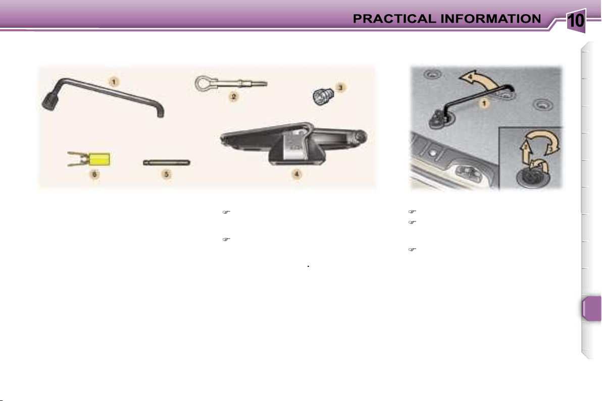
10
117
Parking the vehicle
As far as possible, park the vehi-
cle on level, stable and non-slip-
pery ground.
Apply the handbrake, switch off
the ignition and engage first or re-
verse gear (position
P
for the au-
tomatic gearbox)
.
Access to the spare wheel
Open the boot.
Open the flap using the lug to re-
lease the winch and gain access
to its control nut.
Unscrew the nut fully, using the
wheelbrace
1
, to unroll the winch
cable.
Tools
The following tools are located:
- in the right-hand trim of the boot,
1.
Wheelbrace.
2.
Removable towing eye.
3.
Socket for anti-theft bolts.
- in the holder in the centre of the
spare wheel,
4.
Jack with handle.
5.
Centralising tool.
6.
Bolt cover tool.
CHANGING A WHEEL
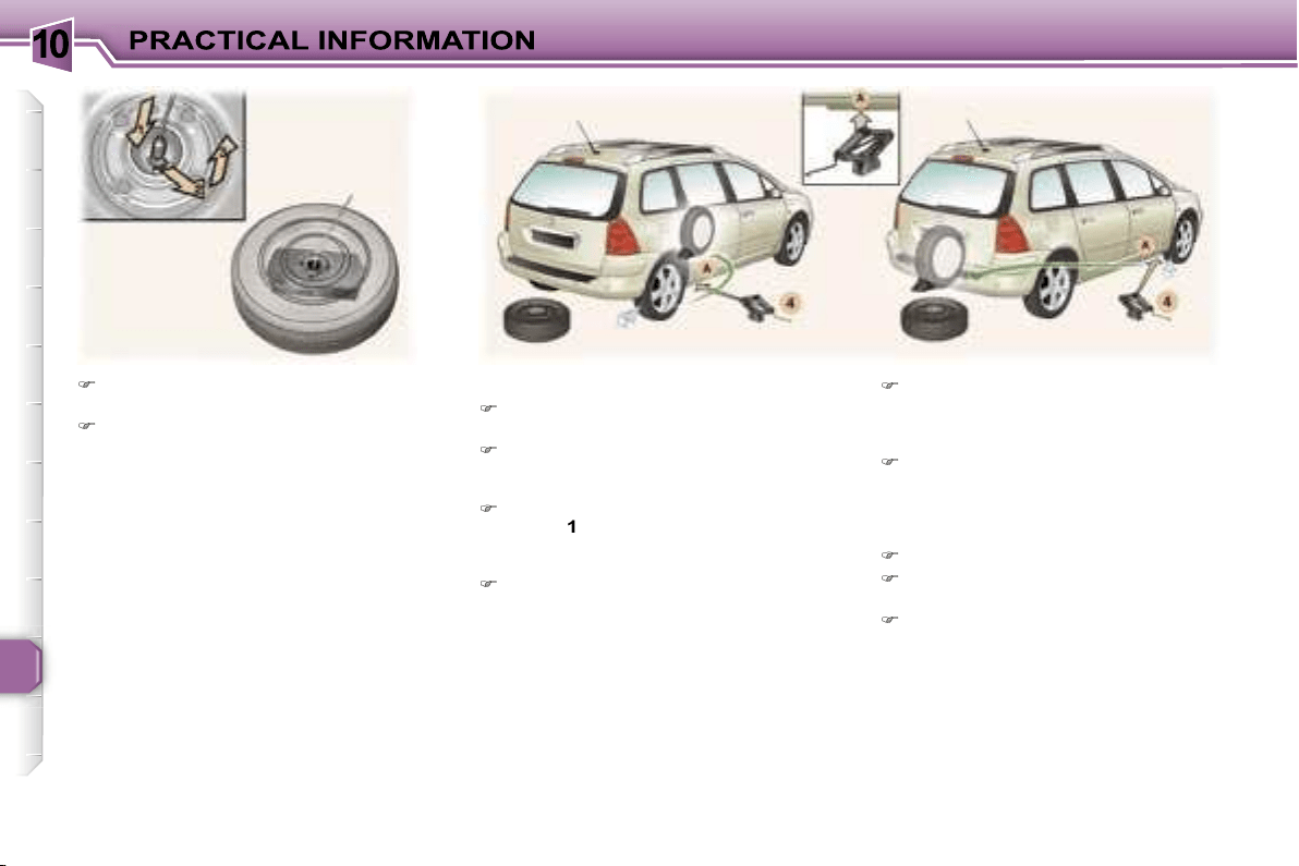
10
118
Detach the wheel/holder assem-
bly from the rear of the vehicle.
Take out the notched hook to re-
lease the wheel, as shown in the
illustration.
Removing the wheel
Slide the holder cover to gain ac-
cess to the tools.
If necessary, place a chock under
the wheel diagonally opposite to
the one to be changed.
Remove the trim, using the wheel-
brace
1
, pulling at the valve pas-
sage hole (for vehicles fitted with
steel wheels).
Loosen the wheel bolts (see §
"Special features of alloy wheels"
for vehicles fitted with alloy
wheels).
Note:
you can use the other end
of the tool
6
to unscrew the wheel
bolts.
Place the jack
4
in contact with one
of the four locating points
A
on the
sub-frame, the one which is clos-
est to the wheel to be changed.
Extend the jack
4
until its base is
in contact with the ground. Ensure
that the centre line of the base of
the jack is straight above the lo-
cating point
A
used.
Raise the vehicle
Remove one bolt and install the
centralising tool
5
in its place.
Unscrew the other bolts and re-
move the wheel.
10
119
Fitting a wheel
Position the wheel using the cen-
tralising tool
5
to assist you.
Tighten the bolts by hand and re-
move the centralising tool
5
.
Partly tighten the bolts using the
wheelbrace
1
.
Fold the jack
4
and
remove it.
Fully tighten the bolts using the
wheelbrace
1
.
Replace the wheel trim, starting
by placing the wheel trim notch
opposite the valve, and press it on
using the palm of the hand.
Put the corresponding tools in the
holder and secure its cover.
Place the holder on the ground
and align the spare wheel on it.
Pass the notched hook into the
holder cover.
Refit the wheel under the vehicle
tightening the winch control nut
using the wheelbrace
1
.
Fully tighten and
check that
the wheel is horizontally flush
against the rear floor
.
Close the flap using the lug to lock
the winch.
Store the rest of the tools in the
right-hand trim of the boot.
For your safety, always
change the wheel:
- on level, stable, non-slippery
ground,
- with the handbrake on and the igni-
tion switched off,
- with first or reverse gear engaged
(position
P
for the automatic gear-
box),
- with the vehicle chocked.
Never go underneath a vehicle that
is supported only by a jack (use a
ramp).
Never refit the holder under the
vehicle without the spare wheel.
Do not use a screwdriver in place
of the wheelbrace to unwind or
wind the winch.
Recommendations when using
the temporary spare wheel*
Your vehicle may be equipped with a
spare wheel which has a different rim
to the standard wheel.
After use, have it replaced as quickly
as possible.
Observe the following instructions in
order to avoid altering the behaviour
of the vehicle:
- do not exceed
50 mph (80 km/h)
,
- do not fit a wheel trim,
- drive with care,
- check the tyre pressure indicated
on the label.
* According to model and country.
After changing the wheel:
- have the correct positioning of the
punctured wheel, the tightening
of the bolts and the tyre pressure
checked by a PEUGEOT dealer as
soon as possible,
- have the punctured tyre repaired
and refit it to the vehicle as soon as
possible,
- have the correct positioning of
the spare wheel checked by a
PEUGEOT dealer.
Wheels fitted with the Tyre
Under-Inflation Detection system
For further information refer to "Tyre
under-inflation detection" in the safe-
ty section.
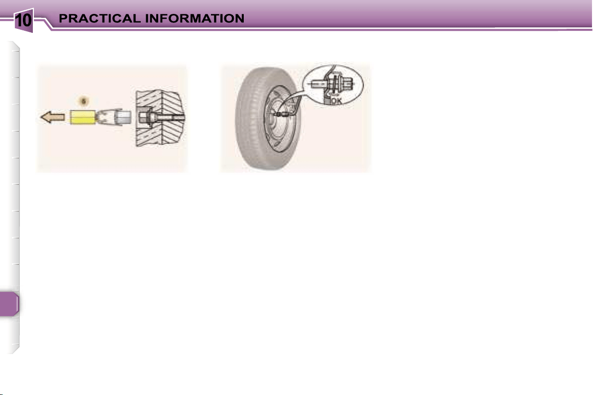
10
120
Bolt covers
Alloy wheel bolts are covered by
chrome trims.
Use the yellow tool
6
to remove the
trims before slackening the bolts.
If your vehicle is fitted with a steel
spare wheel, when fitting it, it is
nor-
mal
when tightening the bolts to no-
tice that the washers do not come
into contact with the rim. The spare
wheel is secured by the cone shape
of each bolt.
Fitting snow tyres
If you fit snow tyres mounted on
steel wheels onto your vehicle, it is
essential
to use special bolts
available from your PEUGEOT dealer.
Special features of alloy
wheels
Fitting the spare wheel
Anti-theft bolts
If your wheels are fitted with an anti-
theft bolt (one per wheel), the chrome
trim must be removed before un-
screwing the bolt using the anti-theft
socket and the wheelbrace.
This anti-theft socket was given to
you on delivery of your vehicle along
with the duplicate keys and the con-
fidential card.
Make a careful note of the code
number engraved on the head of the
anti-theft socket. This will enable you
to obtain a duplicate socket from a
Peugeot dealer.
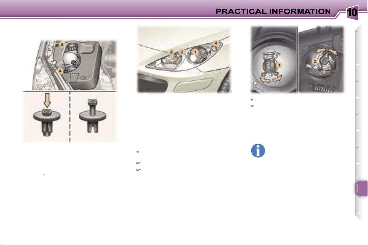
10
121
1. Dipped beam headlamps
(H1-55 W or xenon bulb).
WARNING: RISK OF ELECTROCUTION
Xenon bulbs must be changed by a
PEUGEOT dealer.
2. Main beam headlamps
(H7-55 W).
Remove the protective cover cor-
responding to the faulty bulb.
Disconnect the connector.
Press the end of each securing
clip. Change the bulb.
When fitting the new bulb, ensure
that the direction notches are po-
sitioned correctly and the securing
clips are fixed properly.
Reconnect the connector.
Refit the protective cover.
Front lights
In the engine compartment, on the
right-hand side, remove the style trim*:
- press the centre of each plastic
stud
A
,
- remove each plastic stud,
- remove the style trim.
When you have finished, do not for-
get to put everything back in place
correctly:
- position the style trim*,
- refit each plastic stud
A
by pressing
on it.
* According to engine.
Handle the bulbs with a dry
cloth.
The headlamps are fitted
with polycarbonate glass
with a protective coating.
Do not
clean them with a dry or abrasive
cloth, nor with a detergent or sol-
vent product.
Use a sponge and soapy water.
CHANGING A BULB
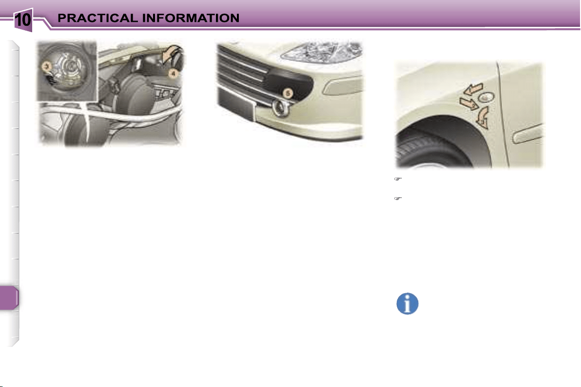
10
122
3. Side lights (W 5 W).
Remove the protective cover cor-
responding to the faulty bulb.
Disconnect the connector.
Remove the bulb and change it.
4. Direction indicators
(PY 21 W amber).
Turn the bulb holder a quarter of a
turn and remove it.
Change the bulb.
Note:
in certain climatic conditions
(low temperature, humidity),
con-
densation inside the headlamp
glass is normal
; it disappears a few
minutes after the lights are switched
on.
5. Fog lamps (H11-55 W).
Contact a PEUGEOT dealer to have
these bulbs changed.
Push the repeater forwards and
release it.
Remove the repeater and change
it.
These can be obtained from a
PEUGEOT dealer.
Amber coloured bulbs, such
as the direction indicators,
must be replaced with bulbs
of identical specification and
colour.
Integrated direction indicator side
repeaters.
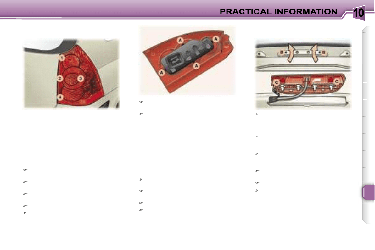
10
123
1. Brake lights (P 21 W).
2. Side lights (x 2) (R 5 W).
3. Direction indicators (P 21 W).
4. Reversing light (P 21 W), left
side.
Fog lamp (P 21 W), right side.
These 6 bulbs are changed by
removing the light:
Remove the respective boot side
trim to access the light,
Remove the mounting nut for the
light inside the boot.
Remove the mounting nut for the
light outside the boot.
Remove the light.
Unclip the harness.
Press the tabs
A
and remove the
bulb holder,
Change the faulty bulb.
Note:
if necessary use the wheel-
brace to remove the nuts.
When refitting, take care to position the
bulb holder and the bulb correctly.
Remove the tailgate upper trim
carefully by unclipping it on either
side, perpendicular to its direction
of engagement.
Insert a screwdriver into the two
outer holes
B
to press on the two
tabs
C
.
Push the light unit outwards while
maintaining the pressure on the
tabs.
Pull the light unit outwards while
tilting it.
Change the faulty bulb.
When refitting, ensure that the
light unit tabs are engaged cor-
rectly and that the tailgate upper
trim has been put back in place
correctly.
Number plate lights (W 5 W)
Insert a small screwdriver in one
of the external holes of the lens
Push the lens outwards to unclip
it.
Remove the lens.
Change the faulty bulb.
Third brake light:
4 W 5 W bulbs.
Rear lights
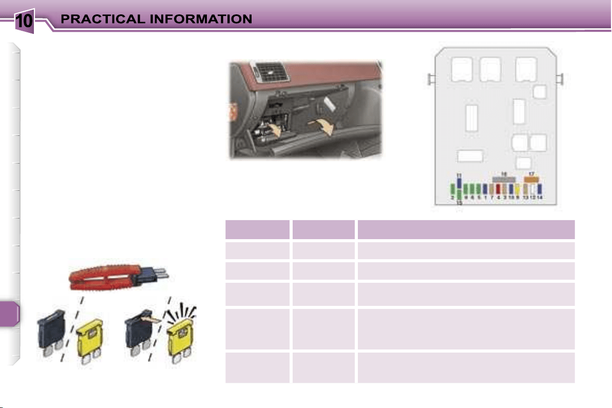
10
124
CHANGING A FUSE
The fuse boxes are placed in the
lower part of the fascia (driver’s side)
and in the engine compartment (left-
hand side).
Correct
Incorrect
Open the glove box lid to gain ac-
cess to the fuses.
Fuse N°
Rating
Functions
F1
15 A
Rear wiper.
F2
30 A
Locking and deadlocking.
F3
5 A
Air bags and pre-tensioners unit.
F4
10 A
Brake and clutch pedals switch, engine coolant
level switch, steering wheel angle sensor,
diagnostic socket, ESP sensor, electrochromatic
mirror, particle emission filter pump.
F5
30 A
Front electric windows and panoramic roof
concealing shutter supply, heated mirrors.
Replacing a fuse
Before replacing a fuse, the cause of
the incident must be found and recti-
fied. The fuse numbers are indicated
on the fuse box.
Always replace a faulty fuse with a
fuse of the same rating (same col-
our).
Use the special pliers located on the
inside of the fascia fuse box cover,
this support also contains the re-
placement fuses.
Fascia fuses
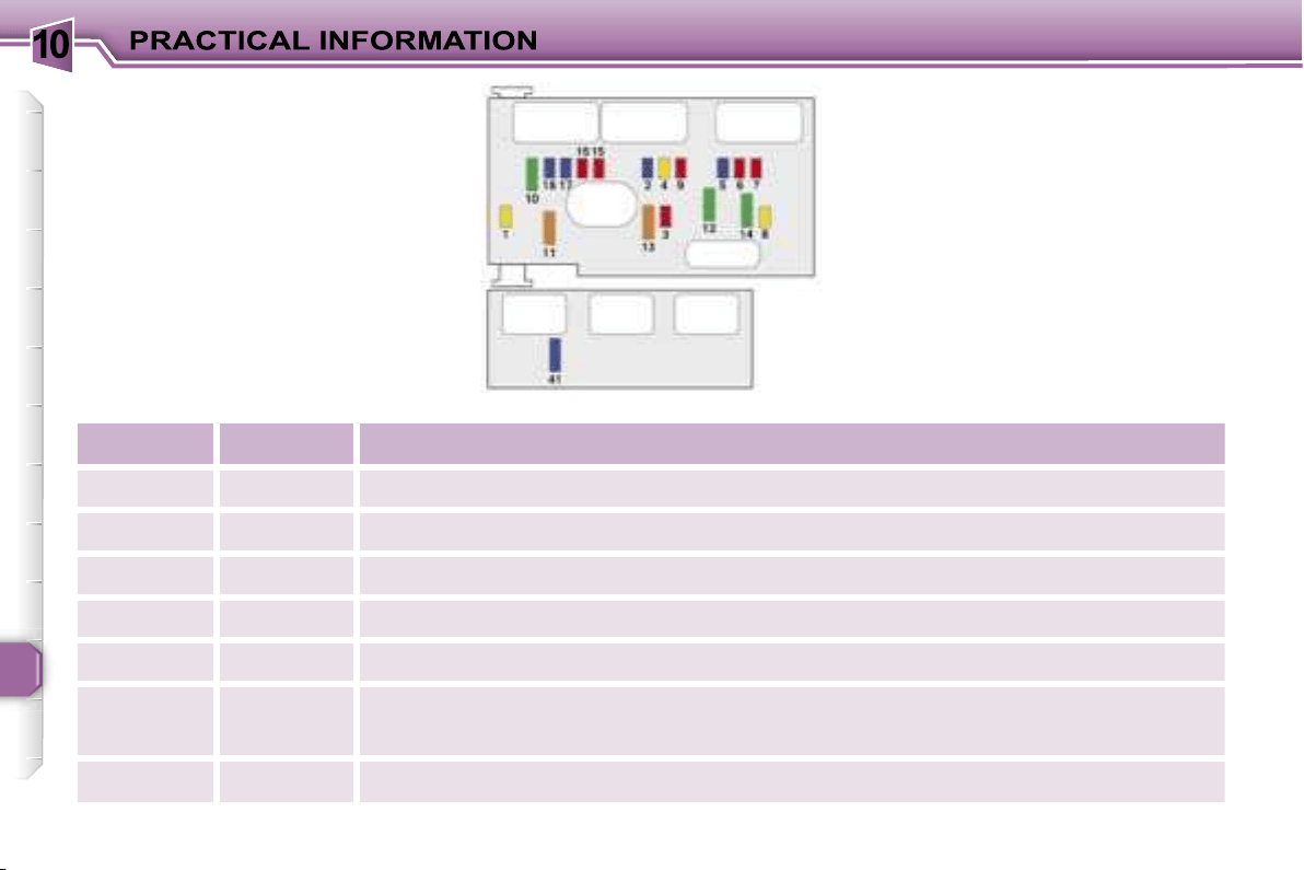
10
126
Engine compartment fuses
To access the fuses located in the
engine compartment (next to the bat-
tery), unclip the fuse box lid.
When you have finished, close the lid
carefully to guarantee the sealing of
the fuse box.
Fuse N°
Rating
Functions
F1
20 A
Engine control unit and fan assembly high speed relays supply.
F2
15 A
Horn.
F3
10 A
Front and rear wash-wipe.
F4
20 A
Headlamp wash.
F5
15 A
Fuel pump and purge canister solenoid valve (2 litre petrol).
F6
10 A
Four speed automatic gearbox control unit, automatic gearbox lever locking control,
push control switch, fan assembly high speed relay, right and left xenon headlamps.
F7
10 A
ABS/ESP control unit, power steering electropump assembly control unit.
10
127
Fuse N°
Rating
Functions
F8
20 A
Starter control.
F9
10 A
Additional heating unit (Diesel), coolant level switch.
F10
30 A
Engine control unit actuators (ignition coil, solenoid valves, oxygen sensors, control units,
injectors, heaters), purge canister solenoid valve (1.6 litre petrol).
F11
40 A
Air conditioning blower.
F12
30 A
Windscreen wipers low/high speed.
F13
40 A
Built-in systems interface supply (ignition positive).
F14
30 A
Air pump (2 litre petrol).
F15
10 A
Right main beam headlamp.
F16
10 A
Left main beam headlamp.
F17
15 A
Left dipped headlamp.
F18
15 A
Right dipped headlamp.
F41
15 A
Six speed automatic gearbox control unit.
10
128
The electrical system of your vehicle is designed to operate with standard or optional equipment.
Before installing other electrical equipment or accessories on your vehicle, contact a PEUGEOT dealer.
PEUGEOT will not accept responsibility for the cost incurred in repairing your vehicle or for rectifying the malfunctions
resulting from the installation of accessories not supplied and not recommended by PEUGEOT and not installed in
accordance with its instructions, in particular where the equipment in question consumes more than 10 milliamperes.
Fuse N°
Rating
Functions
MF1*
30 A
200 W fan assembly.
50 A
400 W and 460 W fan assembly.
MF2*
30 A
ABS/ESP pump.
MF3*
30 A
ABS/ESP solenoid valves.
MF4*
80 A
Built-in systems interface supply.
MF5*
80 A
Built-in systems interface supply.
MF6*
80 A
Passenger compartment fuse box.
MF8*
70 A
Power steering electropump assembly.
* The maxi-fuses provide additional protection for the electrical systems. All work must be carried out by a PEUGEOT
dealer.

10
124
CHANGING A FUSE
The fuse boxes are placed in the
lower part of the fascia (driver’s side)
and in the engine compartment (left-
hand side).
Correct
Incorrect
Open the glove box lid to gain ac-
cess to the fuses.
Fuse N°
Rating
Functions
F1
15 A
Rear wiper.
F2
30 A
Locking and deadlocking.
F3
5 A
Air bags and pre-tensioners unit.
F4
10 A
Brake and clutch pedals switch, engine coolant
level switch, steering wheel angle sensor,
diagnostic socket, ESP sensor, electrochromatic
mirror, particle emission filter pump.
F5
30 A
Front electric windows and panoramic roof
concealing shutter supply, heated mirrors.
Replacing a fuse
Before replacing a fuse, the cause of
the incident must be found and recti-
fied. The fuse numbers are indicated
on the fuse box.
Always replace a faulty fuse with a
fuse of the same rating (same col-
our).
Use the special pliers located on the
inside of the fascia fuse box cover,
this support also contains the re-
placement fuses.
Fascia fuses
10
125
Fuse N°
Rating
Functions
F6
30 A
Rear electric windows supply.
F7
5 A
Front and rear courtesy lights, map reading lights, glove box light, concealing shutter
control.
F8
20 A
Audio equipment, audio/telephone, multifunction display, alarm siren, alarm unit, trailer
fusebox, steering wheel controls supply.
F9
30 A
Front 12 V socket, rear 12 V socket.
F10
15 A
Automatic gearbox control unit, STOP switch, tyre under-inflation detection control unit.
F11
15 A
Diagnostic socket, low current ignition switch, particle emission filter unit.
F12
15 A
Rear parking assistance.
F13
5 A
Engine fusebox supply, rain and brightness sensor.
F14
15 A
Trailer fusebox, instrument panel, automatic air conditioning, air bags and pre-tensioners
unit, hands-free kit.
F15
30 A
Locking and deadlocking supply.
F16
-
PARC shunt.
F17
40 A
Heated rear screen.
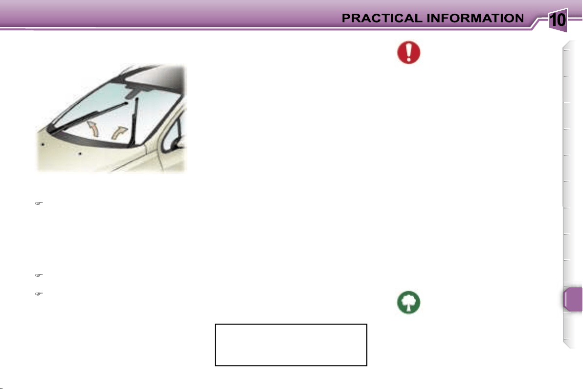
10
129
Special front windscreen wiper
position
Within one minute of switching off
the ignition, operate the wipers
stalk to position the wiper blades
in the centre of the windscreen
(maintenance position).
Changing a wiper blade
Lift the wiper arm, then unclip the
blade and remove it.
Fit the new blade and push back
the arm.
Note:
the shortest blade is fitted on
the vehicle’s right-hand windscreen
wiper arm.
To return the windscreen wipers
to their normal position, switch on
the ignition and operate the wiper
stalk.
BATTERY
To charge the battery using a
battery charger:
- Disconnect the battery starting with
the negative (-) terminal,
- Follow the instructions for use giv-
en by the battery charger manufac-
turer,
- Check that the terminals and
connectors are clean. If they are
covered with sulphate (white or
greenish deposit), disconnect
them and clean them,
- Reconnect starting with the nega-
tive (-) terminal.
Before disconnecting the
battery, you must wait for
2 minutes after switching off
the ignition.
Never disconnect a terminal when the
engine is running.
Never charge a battery without first
disconnecting the terminals.
Close the windows and the roof con-
cealing shutter before disconnecting
the battery. If the windows and the
shutter do not operate normally fol-
lowing reconnection of the battery,
they must be reinitialised (see sec-
tion "Reinitialisation of the electric
windows" and "Panoramic roof").
After every reconnection of the bat-
tery, switch on the ignition and wait
1 minute before starting to allow the
electronic systems to be initialised. If
slight difficulties are experienced af-
ter this, please contact a PEUGEOT
dealer.
Following disconnection of the bat-
tery, the remote control key and the
GPS satellite navigation system must
be reinitialised (see corresponding
section).
It is advisable to disconnect the
battery if the vehicle is not to be
used for a period of more than
one month.
To start the vehicle from
another battery:
- Connect the red cable to the positive
(+) terminals of the two batteries,
- Connect one end of the green
or black cable to the negative (-)
terminal of the slave battery,
- Connect the other end of the green
or black cable to an earth point on
the broken down vehicle as far as
possible from the battery,
- Operate the starter, let the engine
run,
- Wait for the engine to return to idle,
then disconnect the cables.
The batteries contain harmful
substances such as sulphu-
ric acid and lead. They must
be disposed of in accordance
with regulations and must never be
discarded with household waste.
Take used remote control and vehicle
batteries to an approved collection
point.
CHANGING A WINDSCREEN
WIPER BLADE
10
130
ECONOMY MODE FUNCTION
After the engine has stopped, certain
functions (windscreen wiper, elec-
tric windows, courtesy lights, audio
equipment, telephone, dipped head-
lamps, etc.) can only be used for a
combined duration of approximately
thirty minutes, to prevent discharging
the battery.
Once the thirty minutes are over, a
switching to economy mode mes-
sage appears on the multifunction
display and the active functions are
put on standby.
These functions are reactivated au-
tomatically next time the vehicle is
driven.
In order to resume the use of these
functions immediately, the engine
must be started and left to run for a
few minutes.
The time available to you will then be
double the duration for which the en-
gine is left running. However, this pe-
riod will always be between five and
thirty minutes.
A flat battery prevents the
engine from starting.
LOAD REDUCTION
FUNCTION
When driving, certain functions (air con-
ditioning, heated rear screen, heating
system for passenger compartment of
diesel vehicles, etc.) may be switched
off temporarily, depending on the level
of battery charge.
Reactivation of these functions is au-
tomatic, once the battery charge is
sufficient.
Note:
at the risk of discharging the
battery, the functions that have been
switched off may be reactivated
manually.
Note:
if the telephone is be-
ing used when economy
mode starts, it will still be
possible to finish the call.
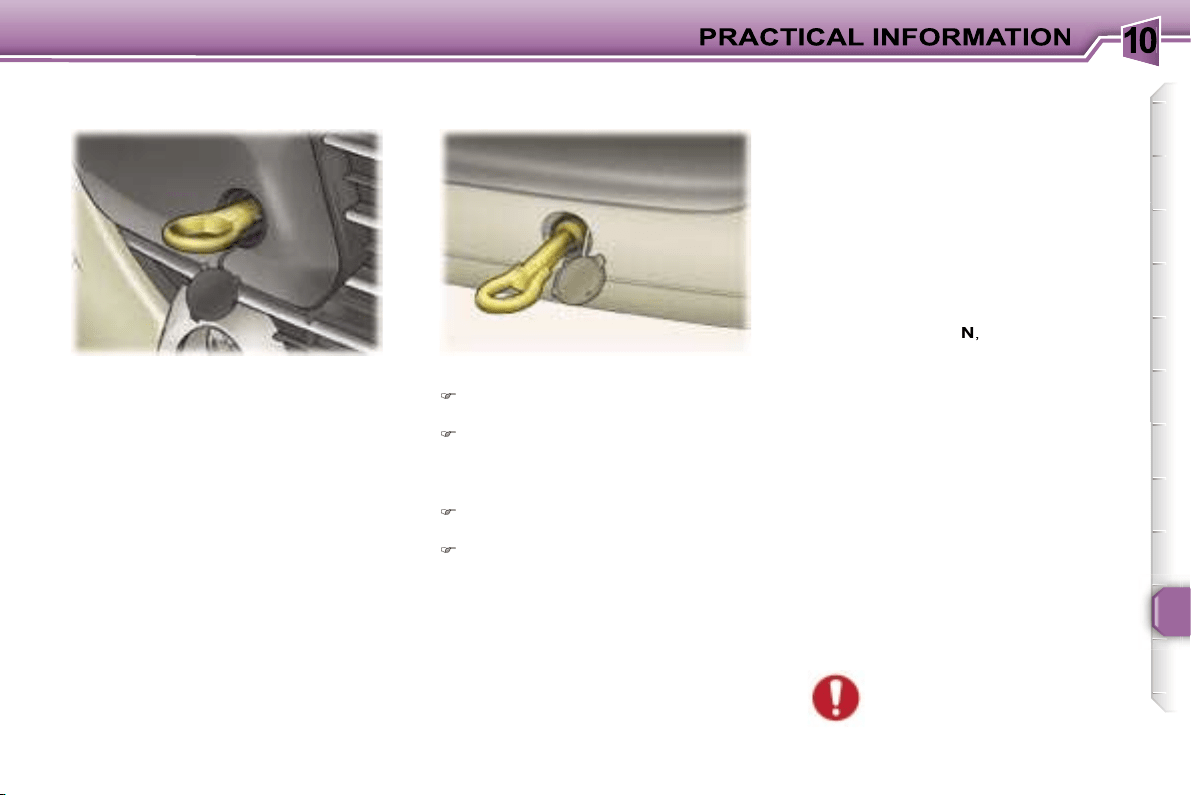
10
131
Without lifting
(4 wheels on the road)
You should always use a towbar.
The removable towing eye is inside
the boot right-hand trim.
From the front:
Unclip the cover, by pressing the
bottom part,
Screw in the removable towing
eye as far as it will go.
Lifting
(2 wheels only on the road)
It is preferable to raise the vehicle
with a professional lifting device.
When towing with the engine
switched off, there is no brak-
ing or steering assistance.
TOWING YOUR VEHICLE
From the rear:
Unclip the top of the cover using a
coin,
Screw in the removable towing
eye as far as it will go.
Special features of the
automatic gearbox
When towing with four wheels on the
ground, the following rules must be
obeyed:
- lever in position
N
,
- tow the vehicle at less than 30 mph
(50 km/h) over a maximum dis-
tance of 30 miles (50 km).
- do not add oil to the gearbox.
10
132
Driving advice
Distribution of loads:
Distribute the
load in the trailer so that the heaviest
items are as close as possible to the
axle and the nose weight approach-
es the maximum permitted without
exceeding it.
Cooling:
towing a trailer on a slope
increases the temperature of the
coolant.
As the fan is electrically controlled,
its cooling capacity is not dependent
on the engine speed.
To lower the engine speed, reduce
your speed.
The maximum towing load on a long
slope depends on the gradient and
the outside temperature.
In all cases, pay attention to the cool-
ant temperature.
If the warning light comes on, stop
the vehicle and switch off the engine
as soon as possible.
Tyres:
check the tyre pressures of
the towing vehicle and of the trailer,
observing the recommended pres-
sures.
Braking:
towing increases the brak-
ing distance.
Lights:
check the electrical signal-
ling on the trailer.
Side wind:
take into acount the in-
creased sensitivity to side wind.
TOWING A TRAILER,
CARAVAN, BOAT, etc.
We recommend the use of original
PEUGEOT towbars that have been
tested and approved from the design
stage of your vehicle and that the fit-
ting of the towbar is entrusted to a
PEUGEOT dealer.
Your vehicle is primarily designed
for transporting people and luggage
but it may also be used for towing a
trailer.
Driving with a trailer subjects the tow-
ing vehicle to more significant stress
and its driver must be particularly
careful.
Air density decreases with altitude,
thus reducing engine performance.
Above 1 000 metres, the maximum
towing load must be reduced by 10 %
and so on for every 1 000 metres of
altitude.
The rear parking assistance function
will be disarmed automatically when
a towbar is fitted.
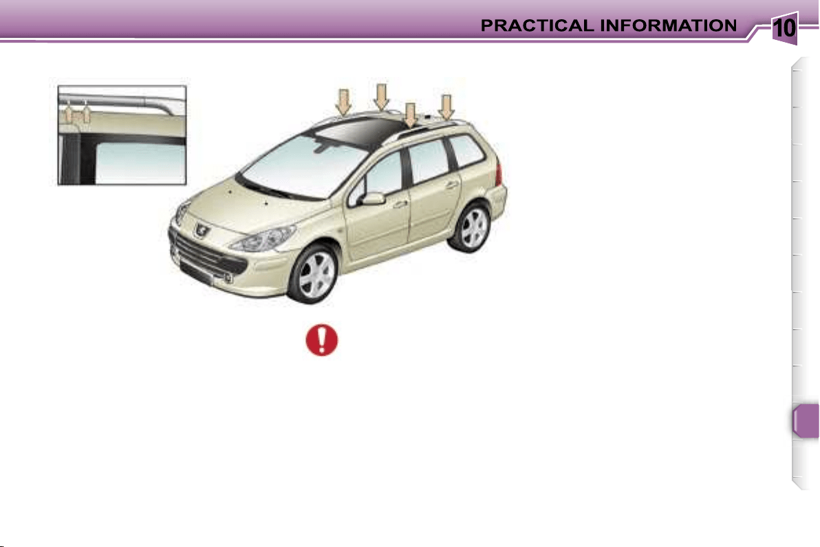
10
133
When fitting transverse roof bars,
ensure that they are positioned
correctly.
The correct positions are shown by
marks on each of the longitudinal
bars.
Use accessories recommended by
PEUGEOT and follow the manufac-
turer’s fitting instructions.
Maximum authorised weight
on the roof rack, for a load-
ing height not exceeding
40 cm (with the exception
of bicycle carriers): 100 kg.
If the height exceeds 40 cm, adapt
the speed of the vehicle to the pro-
file of the road to avoid damaging
the roof bars.
FITTING ROOF BARS
10
134
ACCESSORIES FOR YOUR
307 SW
A wide range of accessories recom-
mended by PEUGEOT and original
parts are offered by the Network.
They all benefit from PEUGEOT’s
recommendation.
These accessories and parts, having
been tested and approved for reli-
ability and safety, are all adapted to
your PEUGEOT vehicle.
The product range offered by
PEUGEOT Accessories is structured
around 5 categories: PROTECTION -
TOURING - IN-CAR TECHNOLOGY -
STYLING - UNIVERSAL.
"Touring":
fixed coat hook on head
restraint, mats, boot tray,
aluminium or PVC sill pro-
tectors.
For leisure pursuits: trans-
verse roof bars, transpor-
tation accessories (bicycle carrier,
ski carrier), roof box, child seats and
booster cushions, additional seats,
rear screen blind, side blinds, audio/
telephone console, front centre arm-
rest, CD storage, cool box.
Trailer towbar which must be fitted by
the PEUGEOT Network.
The fitting of electrical equip-
ment or accessories which
are not recommended by
PEUGEOT may result in a
failure of your vehicle’s electronic
system.
Please note this specific warning.
You are advised to contact a repre-
sentative of the Marque to be shown
the range of recommended equip-
ment and accessories.
"Universal":
windscreen wash fluid, in-
terior and exterior cleaning
and maintenance products.
"Protection":
anti-theft alarm, stolen
vehicle tracking system,
window engraving, lock-
ing wheel nuts, first aid kit,
warning triangle, high vis-
ibility safety jacket, snow
chains.
"In-Car Technology":
audio equipment, audio/
telephone, speakers, ampli-
fiers, hands-free kits, satel-
lite navigation systems, CD
changer, DVD player, con-
nection kit for MP3 player
or portable CD player, entertainment
screen kit, rear parking assistance.
"Styling":
seat covers compatible with
side air bags, aluminium
gear lever knob, fog lamps,
alloy wheels, wheel trims,
styling strips, door spoilers,
sport exhaust.
Note
To prevent the mat from becoming
caught under the pedals:
- ensure that the mat is positioned
and secured correctly,
- never fit one mat on top of another.
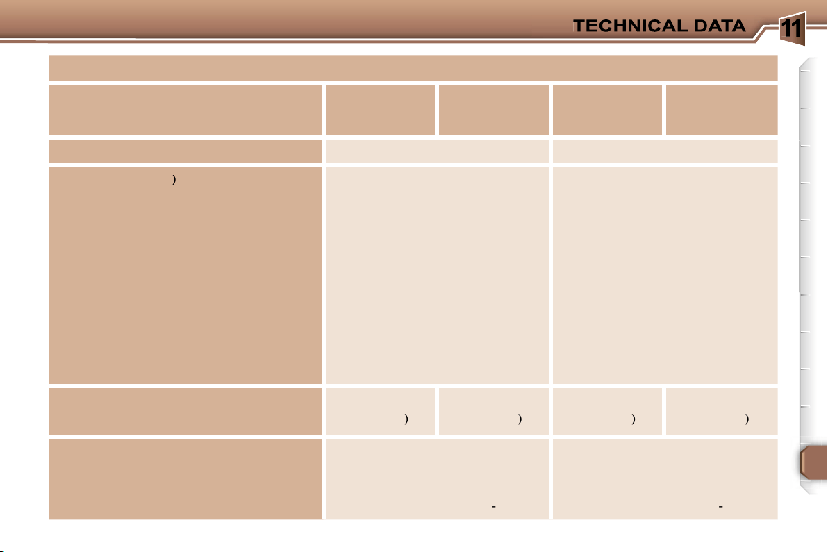
1
135
ENGINES AND GEARBOXES
MODELS:
Model codes: 3H...
NFUC
NFUF
RFJC
RFJF
PETROL ENGINES
1.6 litre
16V 110 bhp
2 litre 16V 143 bhp
Cubic capacity
(cm
3
)
1 587
1 997
Bore x stroke (mm)
78.5 x 82
85 x 88
EU standard max power (kW)
80
103
Max power engine speed (rpm)
5 800
6 000
EU standard max torque (Nm)
147
200
Max torque engine speed (rpm)
4 000
4 000
Fuel
Unleaded
Unleaded
Catalytic converter
Yes
Yes
GEARBOX
Manual
(5
speed
)
Automatic
(4
speed
)
Manual
(5
speed
)
Automatic
(4
speed
)
OIL CAPACITIES (in litres)
Engine (with cartridge replacement)
3.25
5
Gearbox-Final drive
2
-
1.9
-

1
136
ENGINES AND GEARBOXES
MODELS:
Model codes: 3H...
9HXC
9HVC
9HZC
9HYB
RHRH
RHRJ
DIESEL ENGINES
1.6 litre Turbo HDI 16V
90 bhp
1.6 litre Turbo HDI 16V
110 bhp
2 litre 16V Turbo HDI
136 bhp
Cubic capacity
(cm
3
)
1 560
1 560
1 997
Bore x stroke
(mm)
75 x 88.3
75 x 88.3
85 x 88
EU standard max power (kW)
66
80
100
Max power engine speed (rpm)
4 000
4 000
4 000
EU standard max torque (Nm)
215
240
320
Max torque engine speed (rpm)
1 750
1 750
2 000
Fuel
Diesel
Diesel
Diesel
Catalytic converter
Yes
Yes
Yes
Particulate emission filter
No
Yes
No
Yes
Yes
GEARBOX
Manual
(5
speed
)
Manual
(5
speed
)
Manual
(6
speed
)
Auto
(6
speed
)
OIL CAPACITIES (in litres)
Engine (with cartridge replacement)
3.75
3.75
5.25
Gearbox-Final drive
1.9
1.9
2.4
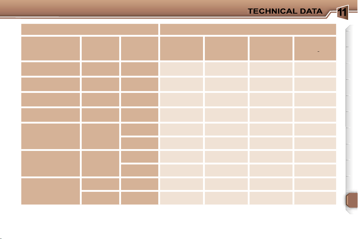
1
137
The consumption values presented here correspond to the values communicated at the time of printing. The consumption
values were established in accordance with EC Directive 80/1268 (as amended). They may vary in relation to the style of driving,
driving conditions, weather conditions, the vehicle load, the maintenance of the vehicle and the use of the accessories.
CONSUMPTION
In accordance with EC Directive 80/1268 (as amended) [In MPG (litres/100 km)]
Engine
Gearbox
Model
Codes
3H...
Urban
Circuit
Inter-urban
Circuit
Mixed
Circuit
Emission
of
CO
2
by
weight g/km
2
2
1.6 litre 16V
Manual
NFUC
28.5 (9.9)
44.8 (6.3)
36.7 (7.7)
178
1.6 litre 16V
Automatic
NFUF
24.8 (11.4)
44.8 (6.3)
34.0 (8.3)
194
2 litre 16V
Manual
RFJC
25.7 (11.0)
46.3 (6.1)
35.8 (7.9)
188
2 litre 16V
Automatic
RFJF
23.2 (12.2)
44.8 (6.3)
33.6 (8.4)
199
1.6 litre Turbo HDI
16V 90 bhp
Manual
9HXC
44.8 (6.3)
62.8 (4.5)
55.4 (5.1)
134
9HVC
44.8 (6.3)
62.8 (4.5)
55.4 (5.1)
134
1.6 litre Turbo HDI
16V 110 bhp
Manual
9HZC
44.8 (6.3)
62.8 (4.5)
55.4 (5.1)
134
9HYB
45.6 (6.2)
64.2 (4.4)
56.5 (5.0)
131
2 litre 16V turbo HDI
Manual
RHRH
38.7 (7.3)
60.1 (4.7)
50.4 (5.6)
148
Automatic
RHRJ
29.7 (9.5)
52.4 (5.4)
40.9 (6.9)
183
1
138
WEIGHTS AND TOWING LOADS (in kg)
The GTW and towing load values indicated are valid up to a maximum altitude of 1 000 metres; the towing load mentioned
must be reduced by 10 % for each additional 1 000 metres of altitude.
The speed of a towing vehicle must not exceed 60 mph (100 km/h) (comply with the legislation in force in your country).
High exterior temperatures may result in a reduction of the performance of the vehicle in order to protect the engine; if the
exterior temperature is above 37 °C, limit the towed weight.
* The weight of the braked trailer can be increased, within the GTW, if the GVW of the towing vehicle is reduced by an equal
amount; warning, towing using a lightly loaded towing vehicle may have an adverse effect on its road holding.
Petrol engines
1.6 litre 16V
2 litre 16V
Gearbox
Manual
Automatic
Manual
Automatic
Model codes: 3H...
NFUC
NFUF
RFJC
RFJF
•
Kerb weight
1 435
1 469
1 466
1 493
•
Payload
505
511
504
492
•
Gross vehicle weight (GVW)
1 940
1 980
1 970
1 985
•
Gross train weight (GTW)
on a 12 % gradient
2 900
2 900
3 200
3 200
on an 8 % gradient
2 900
2 900
3 200
3 200
•
Braked trailer (within GTW)
on a 12 % gradient
960
920
1 230
1 215
on an 8 % gradient
960
920
1 230
1 215
•
Braked trailer* (with load transfer
within GTW)
1 200
1 200
1 500
1 500
•
Unbraked trailer
715
730
730
745
•
Recommended nose weight
60
60
60
60
1
139
WEIGHTS AND TOWING LOADS (in kg)
The GTW and towing load values indicated are valid up to a maximum altitude of 1 000 metres; the towing load mentioned
must be reduced by 10 % for each additional 1 000 metres of altitude.
The speed of a towing vehicle must not exceed 60 mph (100 km/h) (comply with the legislation in force in your country).
High exterior temperatures may result in a reduction of the performance of the vehicle in order to protect the engine; if the
exterior temperature is above 37 °C, limit the towed weight.
* The weight of the braked trailer can be increased, within the GTW, if the GVW of the towing vehicle is reduced by an equal
amount; warning, towing using a lightly loaded towing vehicle may have an adverse effect on its road holding.
Diesel engines
1.6 litre Turbo HDI 16V
90 bhp
1.6 litre Turbo HDI 16V
110 bhp
2 litre 16V Turbo HDI
Gearbox
Manual
Manual
Manual
Automatic
Model codes: 3H...
9HXC
9HVC
9HZC
9HYB
RHRH
RHRJ
•
Kerb weight
1 469
1 492
1 492
1 483
1 575
1 606
•
Payload
501
508
508
517
505
509
•
Gross vehicle weight (GVW)
1 970
2 000
2 000
2 000
2 080
2 115
•
Gross train weight (GTW)
on a 12 % gradient
3 130
3 130
3 130
3 130
3 450
3 450
on an 8 % gradient
3 130
3 130
3 130
3 130
3 450
3 450
•
Braked trailer
(within GTW)
on a 12 % gradient
1 160
1 300
1 130
1 130
1 370
1 335
on an 8 % gradient
1 160
1 300
1 130
1 130
1 370
1 335
•
Braked trailer* (with load transfer
within GTW)
1 300
1 300
1 300
1 300
1 500
1 500
•
Unbraked trailer
730
745
745
740
750
750
•
Recommended nose weight
60
60
60
60
60
60
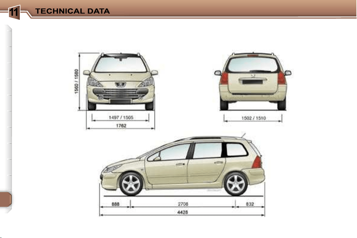
1
140
DIMENSIONS (in mm)
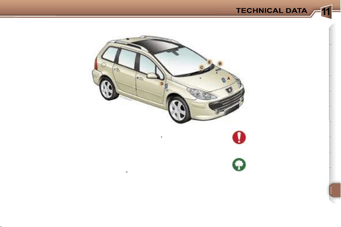
1
141
A. Manufacturer’s plate.
B. Serial number on the
bodywork.
C. Serial number on the fascia.
D. Tyres and paint colour
reference
.
The label
D
on the pillar, near the
hinges of the driver’s door, gives:
- the wheel and tyre sizes,
- the brands of tyres* approved by
the manufacturer,
- the tyre pressures,
-
the paint colour reference*.
The tyre pressure must be
checked when the tyre is
cold, at least once a month.
Low tyre pressures increase
fuel consumption.
IDENTIFICATION FEATURES OF YOUR 307 SW
E. Fuel consumption figures* in
the corner of the windscreen.
*
According to country.
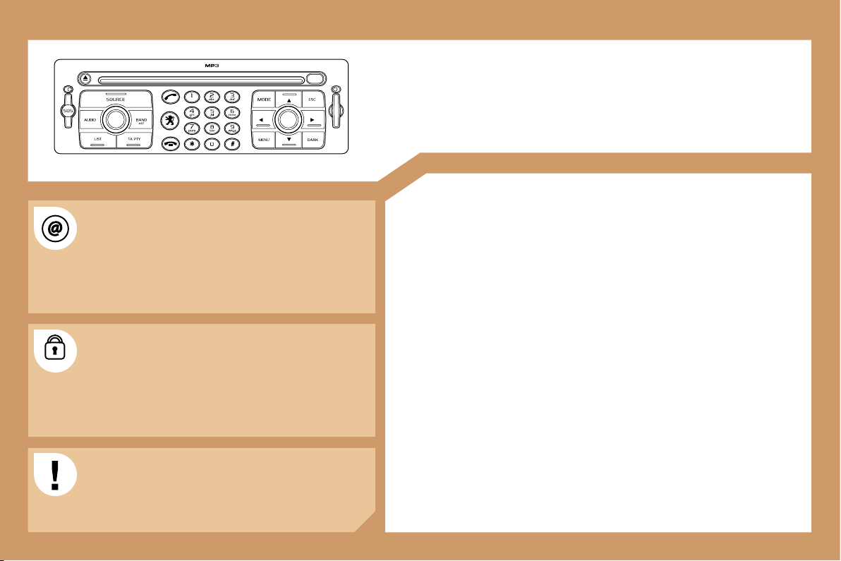
142
RT3
AUDIO EQUIPMENT/TELEPONE/GPS
CONTENTS
• 01 First steps
pg. 143
• 02 General menu
pg. 144
• 03 GPS
pg. 145
• 04 Audio
pg. 152
• 05 Telephone
pg. 154
• 06 Control short-cuts
pg. 157
• 07 Configuration
pg. 159
• 08 Display flow charts
pg. 161
The INFOTEC internet site provides additional
animated information on the RT3. It can be consulted
at the following address:
http://public.infotec.peugeot.com
Simple registration permits access and free
consultation of the handbook.
The RT3 GPS audio/telephone is coded in such a
way that it will only operate in your vehicle. If it is to be
installed in another vehicle, contact your PEUGEOT
dealer for configuration of the system.
For safety reasons, the driver must carry out
operations which require prolonged attention while
the vehicle is stationary.
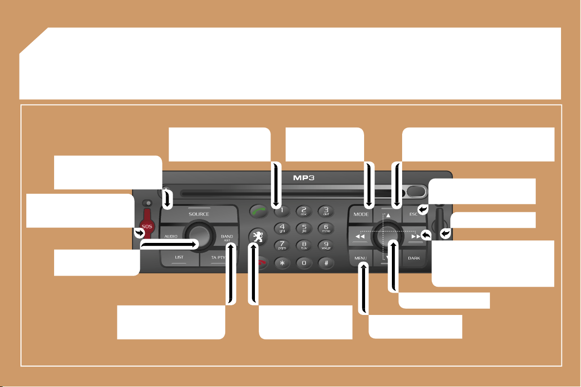
143
01 FIRST STEPS
Selection of the source: radio,
CD, CD changer and auxiliary
(AUX).
Long press on the SOS button:
emergency call.
On/Off.
Volume adjustment.
Selection of the FM1, FM2,
FMast, AM wavebands.
Keypad for entering
descriptions by means of
successive presses.
Access to the "PEUGEOT"
services menu.
Displaying of the general
menu.
SIM card flap.
Cancellation of the current
operation.
- Selection of a lower/higher frequency.
- Selection of the previous/next CD.
- Selection of the previous/next MP3
directory.
- Automatic search for a lower/
higher frequency.
- Selection of the previous/next
track on CD or MP3.
Selection and
confirmation.
Selection of the
screen display mode.
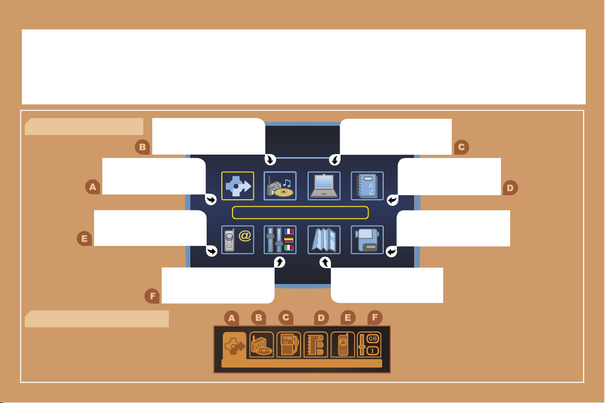
144
02 GENERAL MENU
AUDIO FUNCTIONS: radio,
options.
NAVIGATION: GPS, traffic
information, options.
> COLOUR DISPLAY DT
TRIP COMPUTER: speed,
consumption, distance.
DIRECTORY: telephone
and GPS.
VIDEO: activation, parameters.
MAP: GPS, details, orientation.
CONFIGURATION: vehicle
parameters, display, time,
languages.
TELEPHONE functions:
services, telephone functions,
SMS.
> MONOCHROME DISPLAY CT
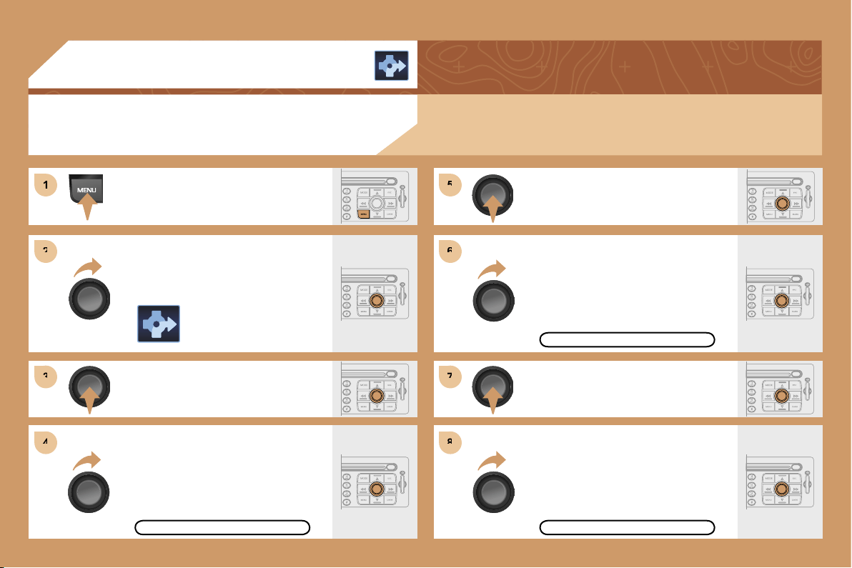
1
1
2
2
3
3
5
5
7
7
4
4
6
6
8
8
145
03 GPS
ENTERING AN ADDRESS AND
ACTIVATING GUIDANCE
Press the MENU button.
Turn the dial and select the
NAVIGATION function.
Press the dial to confirm the selection.
Turn the dial and select the
DESTINATION CHOICE function.
Press the dial to confirm the selection.
Press the dial to confirm the selection.
Turn the dial and select the
ENTER AN ADDRESS function.
Turn the dial and select the TOWN
function.
TOWN
ENTER AN ADDRESS
The navigation CD ROM:
Insert the navigation CD ROM in the drive on the control panel and leave it
there in order to use the Navigation functions.
DESTINATION CHOICE
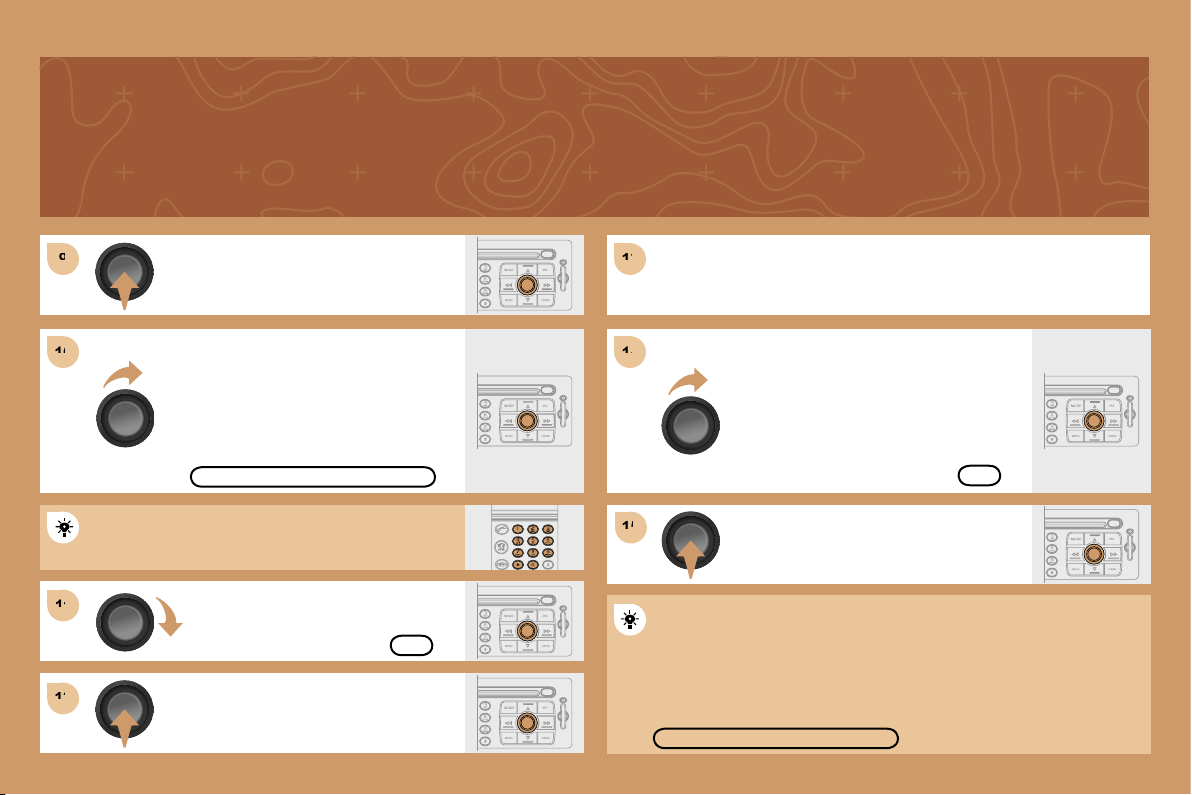
9
9
11
11
12
12
13
13
15
15
10
10
14
14
146
Press the dial to confirm the selection.
Turn the dial and select the letters of
the town one by one confirming each
time by pressing the dial.
Turn the dial and select the OK
function.
Press the dial to confirm the selection.
Use the alphanumeric keypad to enter the letters and
digits and * to correct.
Press the dial to confirm the selection.
Select the OK function on the
ENTER AN ADDRESS page.
Repeat steps 8 to 12 for the ROAD and N°
functions.
PARIS
OK
OK
Select the STORE function to record the address entered in a
directory record and press the dial to confirm the selection.
STORE
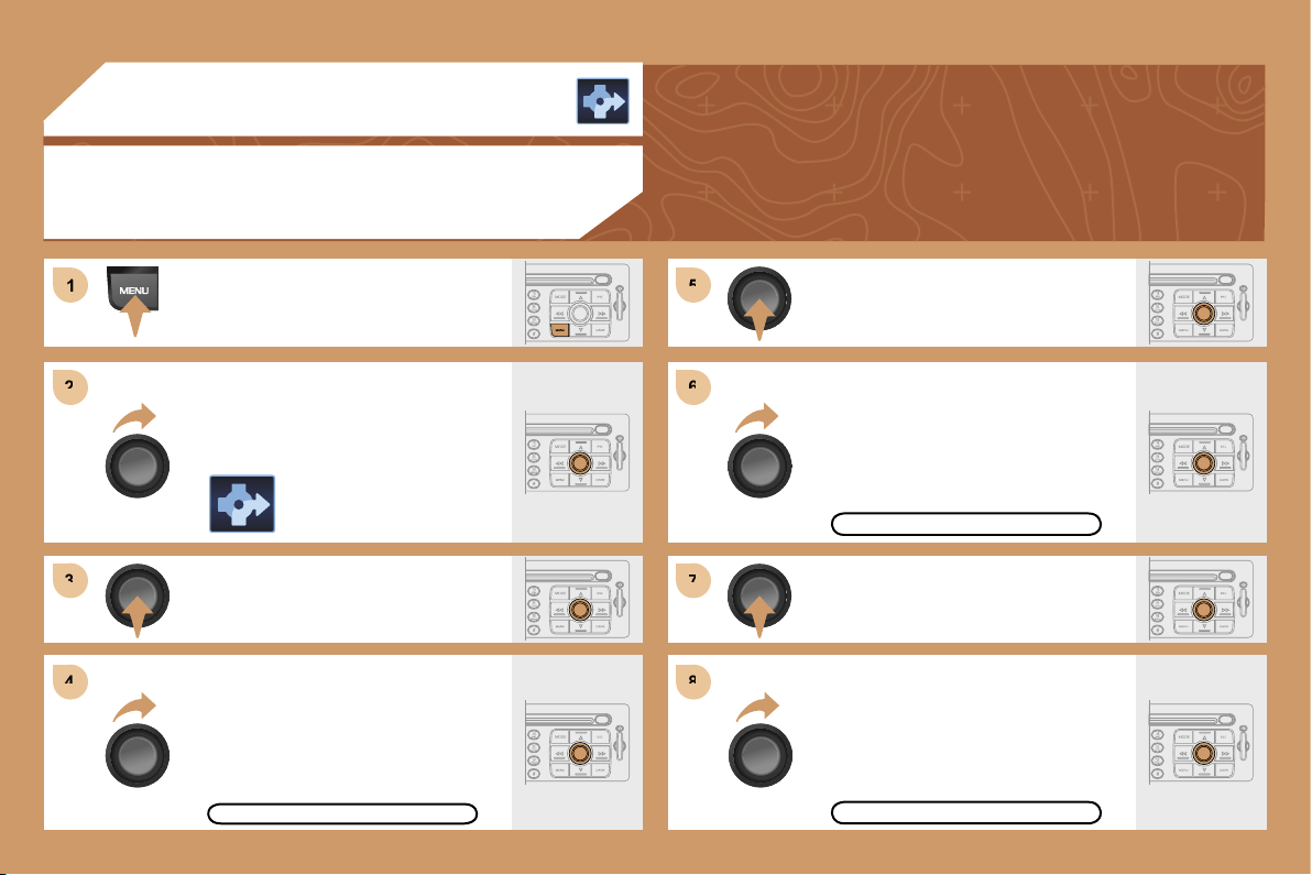
1
1
2
2
3
3
4
4
5
5
6
6
7
7
8
8
147
03 GPS
GUIDANCE OPTIONS
Press the MENU button.
Turn the dial and select the
NAVIGATION function.
Press the dial to confirm the selection.
Turn the dial and select the
GUIDANCE OPTIONS function.
Press the dial to confirm the selection.
Press the dial to confirm the selection.
Turn the dial and select the DEFINE
CALCULATION CRITERIA function.
Turn the dial and select, for example,
the FASTEST ROUTE function.
GUIDANCE OPTIONS
FASTEST ROUTE
DEFINE CALCULATION CRITERIA
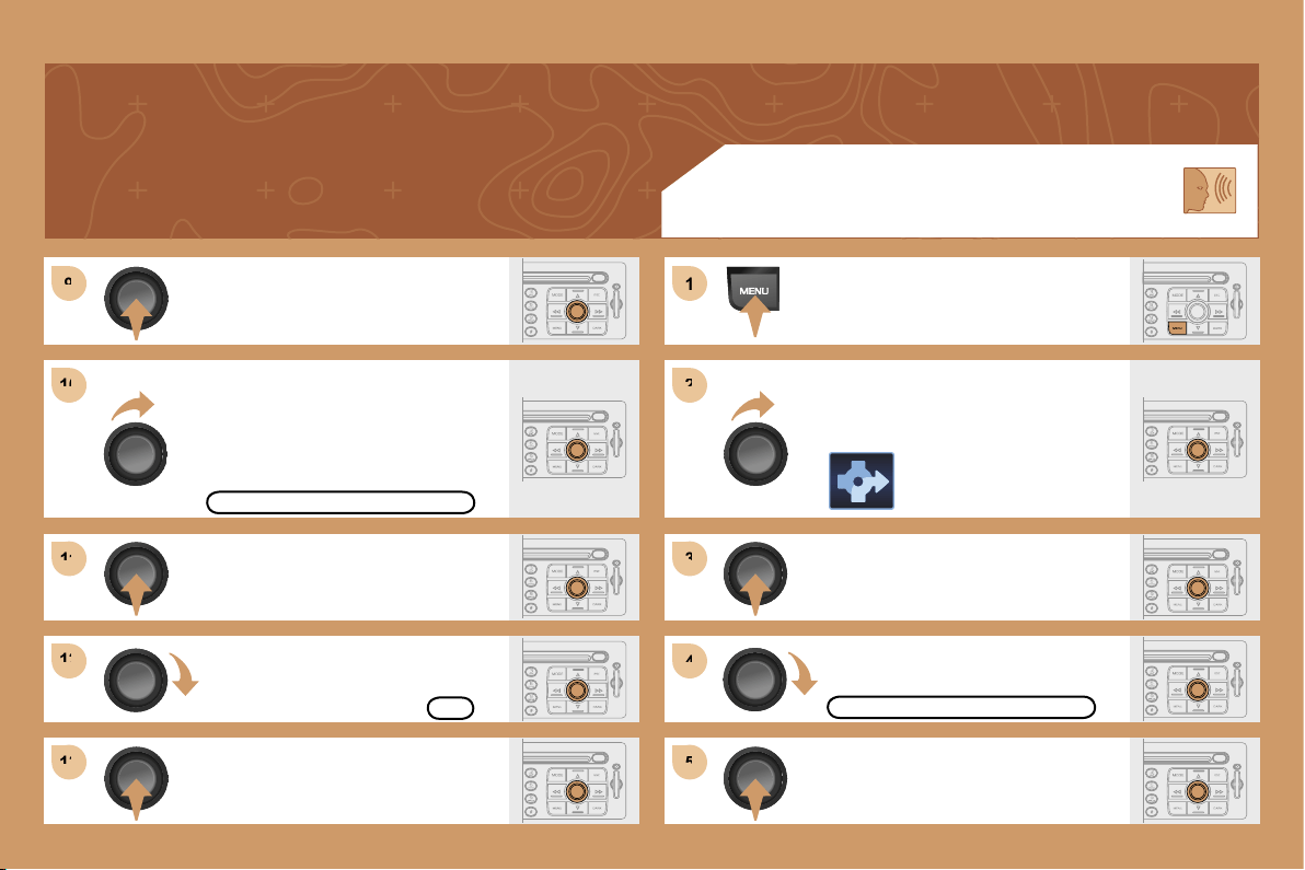
9
9
10
10
11
11
12
12
13
13
1
1
2
2
3
3
4
4
5
5
148
Press the dial to confirm the selection.
Press the dial to confirm the selection.
Turn the dial and select the WITH
TOLLS function if it is not ticked.
SPEECH SYNTHESIS
Press the MENU button.
Turn the dial and select the
NAVIGATION function.
Press the dial to confirm the selection.
Turn the dial and select the
GUIDANCE OPTIONS function.
WITH TOLLS
GUIDANCE OPTIONS
Press the dial to confirm the selection.
Turn the dial and select the OK
function.
Press the dial to confirm the selection.
OK
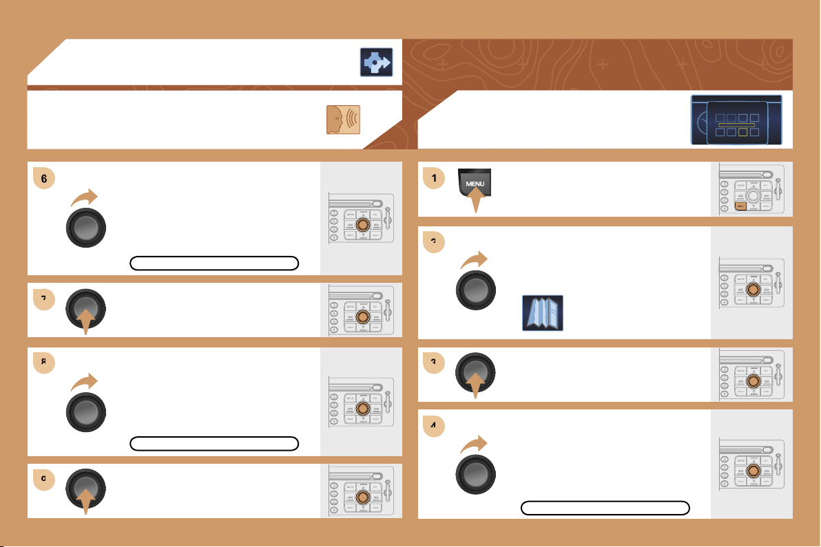
6
7
7
8
8
9
9
1
1
2
2
3
3
4
4
149
Press the dial to confirm the selection.
Turn the dial and select the ADJUST
SPEECH SYNTHESIS function.
Turn the dial and select the ACTIVATE
function.
Press the dial to confirm the function.
03 GPS
SPEECH SYNTHESIS
ADJUST SPEECH SYNTHESIS
ACTIVATE
Press the MENU button.
Turn the dial and select the MAP
function.
Press the dial to confirm the selection.
Turn the dial and select
the MAP DETAILS function.
Permits selection of the services
which can be seen on the map
(hotels, restaurants...).
ACTIONS ON THE MAP
(Colour display DT only)
MAP DETAILS
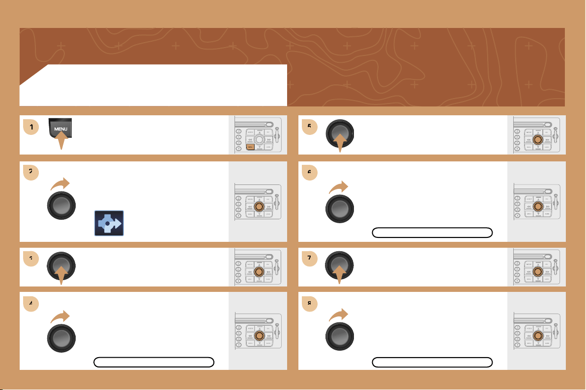
1
1
2
2
3
3
4
4
5
5
6
6
7
7
8
8
150
ACTIVATING THE ROUTE FILTER
Press the MENU button.
Turn the dial and select the
NAVIGATION function.
Press the dial to confirm the selection.
Turn the dial and select the TMC
TRAFFIC INFORMATION function.
TMC TRAFFIC INFORMATION
Press the dial to confirm the selection.
Turn the dial and select the FILTER
THE TMC INFORMATION function.
FILTER THE TMC INFORMATION
Press the dial to confirm the selection.
Turn the dial and select the
ACTIVATE ROUTE FILTER function.
ACTIVATE ROUTE FILTER
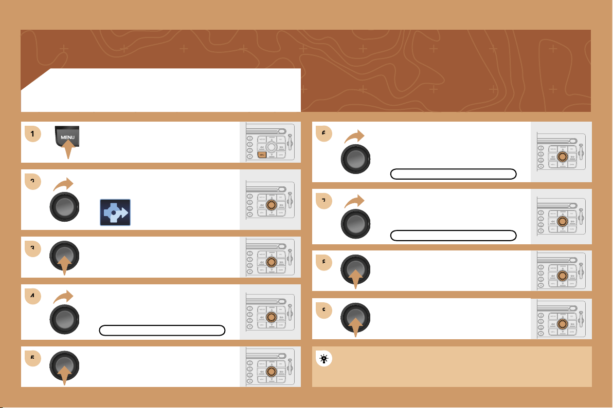
1
1
2
2
3
3
4
4
6
6
5
5
7
7
8
8
8
8
151
ADDING A STAGE
Press the MENU button.
Turn the dial and select the
NAVIGATION function.
Press the dial to confirm the selection.
Turn the dial and select the
STAGES AND ROUTE function.
STAGES AND ROUTE
Turn the dial and select the ADD A
STAGE function. Press the dial to
confirm the selection.
ADD A STAGE
Press the dial to confirm the selection.
Enter an address (see GPS section)
or select SERVICE CHOICE
(restaurants, hotel...).
SERVICE CHOICE
Press the dial to confirm the selection.
Press the dial to confirm the order of
the stages.
The stage must be completed or deleted before the guidance can
continue to the next destination.
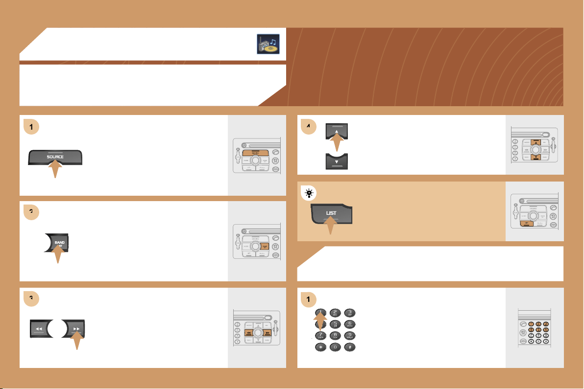
1
1
2
2
3
3
4
4
1
1
152
04 AUDIO
RADIO
SELECTING A STATION
RADIO
STORING A STATION
Press the SOURCE button several
times in succession and select the
RADIO.
Press the BAND AST button to select
a waveband: FM1, FM2, FMast, AM.
Briefly press one of the buttons
to carry out an automatic search
of the radio stations.
Press one of the buttons on the
alphanumeric keypad for more than
2 seconds to store the frequency of
the current station.
Press one of the buttons to carry out
a manual search of the radio stations.
Press the LIST button to display
the list of stations received locally.
To update this list, press for more
than two seconds.
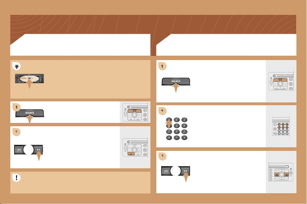
2
2
1
1
2
2
3
3
1
1
153
CD
PLAYING A CD OR AN MP3 COMPILATION
CD CHANGER
PLAYING A CD (NOT MP3 COMPATIBLE)
If the GPS is used, the navigation CD ROM must
remain in the RT3 audio/telephone player. In this case,
audio CDs must be inserted in the CD changer.
Otherwise, insert an audio CD or an MP3 compilation
in the player, play begins automatically.
If the player already contains a disc,
press the SOURCE button several
times in succession and select CD.
Press one of the buttons to select a
track on the CD.
Press the LIST button to display
the list of tracks on the CD or of the
directories of the MP3 compilation.
Insert one or more CDs in the changer.
Press the SOURCE button several
times in succession and select CD
CHANGER.
Press one of the buttons on the
alphanumeric keypad to select the
corresponding CD.
Press one of the buttons to select a
track on the CD.
The playing and displaying of an MP3 compilation may depend on
the recording programme and/or the parameter settings used. We
recommend use of the ISO 9660 recording standard.
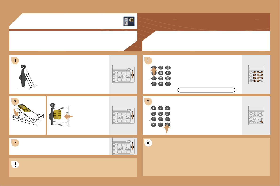
1
1
2
2
3
3
1
1
2
2
154
05 TELEPHONE
INSTALLING THE SIM CARD
(NOT SUPPLIED)
ENTERING THE PIN CODE
Access the slot by pressing the button
using the tip of a pen.
Install the SIM
card in the holder
and then insert it
in the slot.
To remove the SIM card, repeat step 1.
The SIM card must be installed and removed with the RT3 GPS
The SIM card must be installed and removed with the RT3 GPS
audio/telephone switched off and the ignition off.
Enter the PIN code on the keypad.
Confirm the PIN code by pressing
button #.
PIN CODE
When entering the PIN code, tick the STORE PIN tab to gain access
When entering the PIN code, tick the STORE PIN tab to gain access
to the telephone without having to enter this code when it is used
to the telephone without having to enter this code when it is used
subsequently.
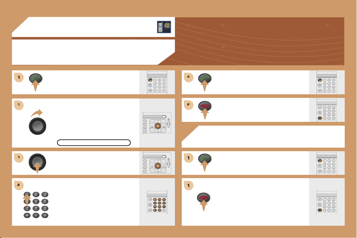
1
1
2
2
3
3
4
4
5
5
6
6
1
1
1
1
155
05 TELEPHONE
CALLING A CONTACT
Turn the dial and select the DIAL
function.
Press the PICK UP button to display
the superimposed telephone menu.
Press the dial to confirm the selection.
Dial the telephone number of your
contact using the alphanumeric
keypad.
Press the PICK UP button to call
the number dialled.
Press the HANG UP button to end
the call.
ACCEPTING OR REFUSING A CALL
Press the PICK UP button.
Press the HANG UP button.
The call will then be transferred to
your voice mailbox.
DIAL
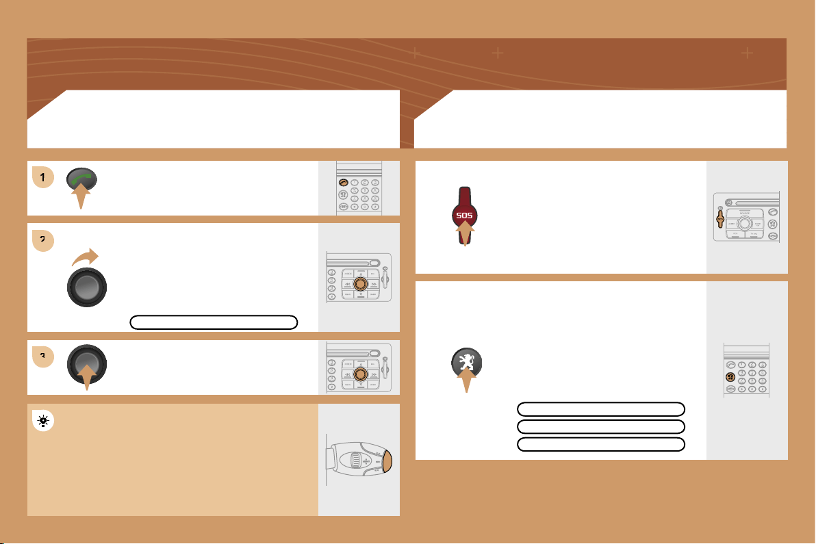
1
2
2
3
3
156
Turn the dial and select the MAILBOX
function.
Press the PICK UP button.
Press the dial to confirm the selection.
CONSULTING THE MAILBOX
CONSULTING THE SERVICES
Press the LION button to gain access
to the
PEUGEOT
services.
The services and options are subject
to conditions and availability.
In an emergency, press the SOS
button until you hear an audible
signal and a CONFIRMATION/
CANCELLATION screen is displayed.
The services and options are subject
to conditions and availability.
MAILBOX
OPERATOR SERVICES
PEUGEOT ASSISTANCE
CUSTOMER CONTACT CENTRE
Press the end of the steering wheel stalk for more
than 2 seconds to gain access to the telephone
menu: call log, directory, mailbox.
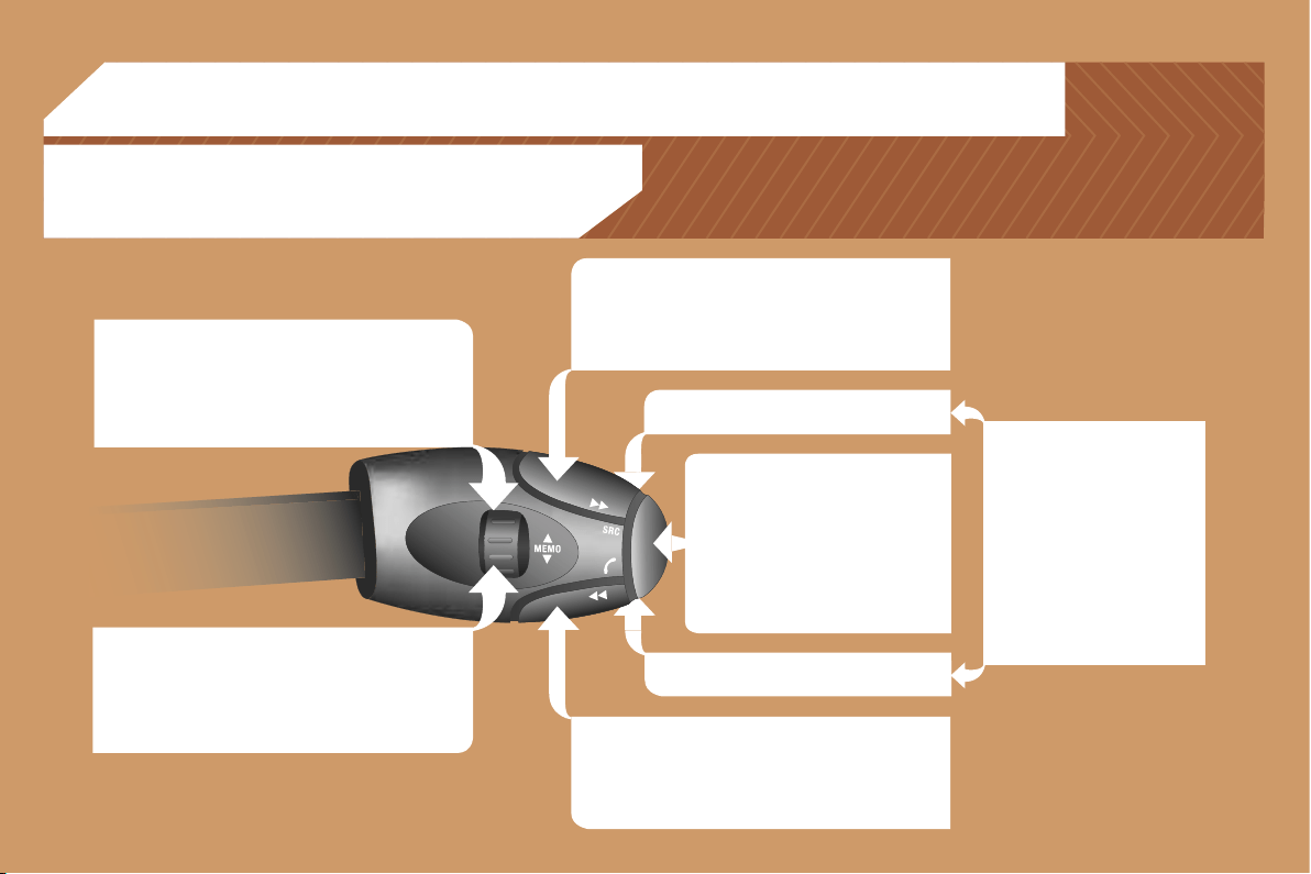
157
RADIO: selection of the previous stored station.
CD CHANGER: selection of the previous CD.
Selection of the previous item on a menu.
MP3: selection of the previous directory.
RADIO: selection of the next stored station.
CD CHANGER: selection of the next CD.
Selection of the next item on a menu.
MP3: selection of the next directory.
RADIO: automatic search for a higher frequency.
CD/CD CHANGER/MP3: selection of the next track.
Continuous press: fast forwards play.
RADIO: automatic search for a lower frequency.
CD/CD CHANGER/MP3: selection of the previous
track.
Continuous press: fast backwards play.
- Change of sound source.
- Confirmation of a selection.
- Pick up/Hang up the telephone.
- Press for more than 2 seconds:
access to the telephone menu.
Volume increase.
Volume decrease.
06 CONTROL SHORT-CUTS
STEERING WHEEL CONTROLS
Mute: by pressing the volume
increase and decrease
buttons simultaneously.
The sound is restored by
pressing one of the two
volume buttons.
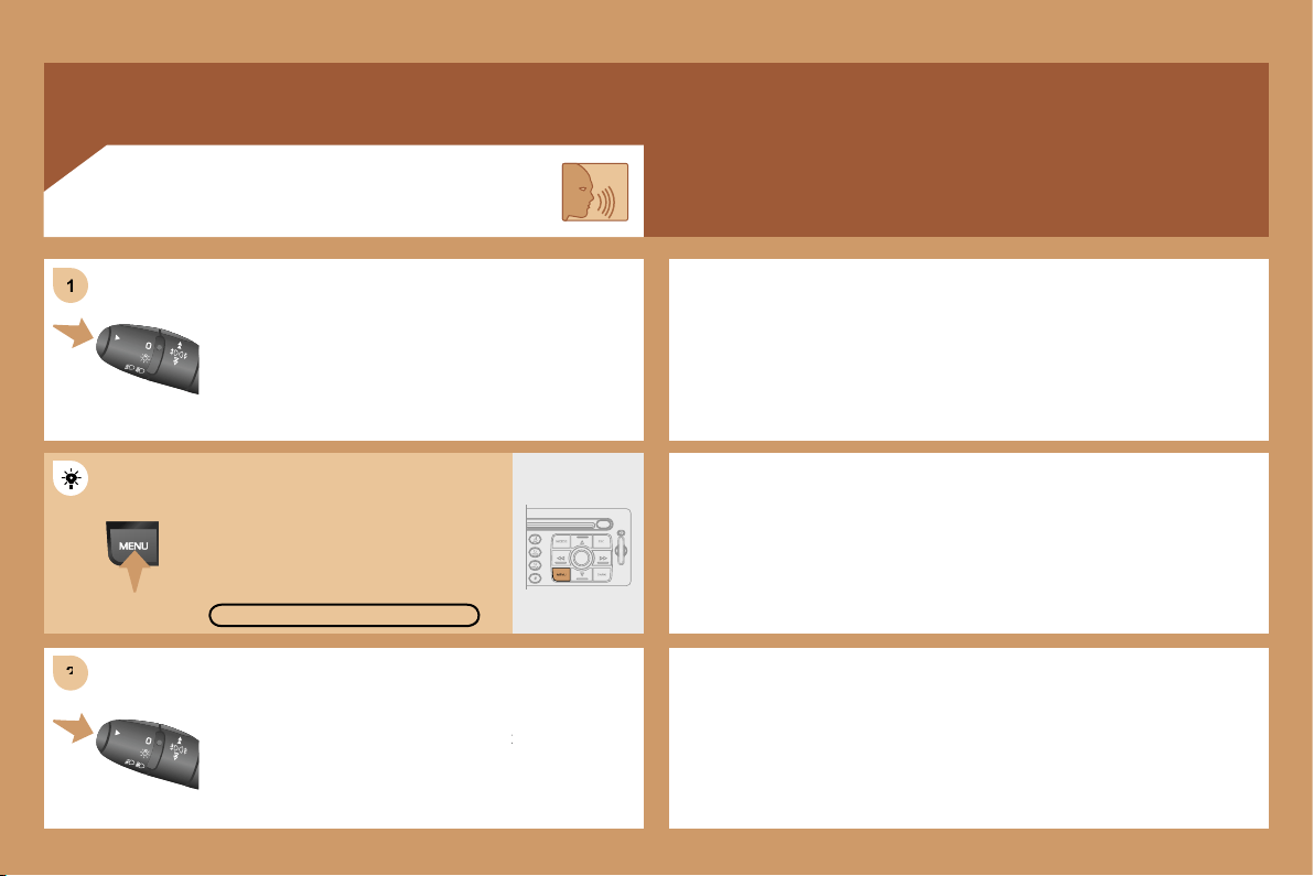
2
2
1
1
158
Press the end of the lights stalk to start the voice
Press the end of the lights stalk to start the voice
recognition.
Say the words one by one and wait for the audible
Say the words one by one and wait for the audible
confirmation signal between each word.
The list which follows is not exhaustive.
AUDIO
- RADIO then NEXT
- CD PLAYER then NEXT TRACK
- CD CHANGER then NEXT DISK
TELEPHONE
- TELEPHONE then REDIAL
- TELEPHONE then DIRECTORY then DESCRIPTION
- TELEPHONE then VOICE MAILBOX
GPS
- NAVIGATION then SHOW then DESTINATION
- NAVIGATION then STOP
- NAVIGATION then ZOOM IN
VOICE COMMANDS
To display the list of available voice commands, press
To display the list of available voice commands, press
the end of the lights stalk to start the voice recognition,
the end of the lights stalk to start the voice recognition,
then say HELP or WHAT CAN I SAY.
For the same operation, press and
hold the MENU button and select
the function VOICE COMMANDS
LIST.
VOICE COMMANDS LIST
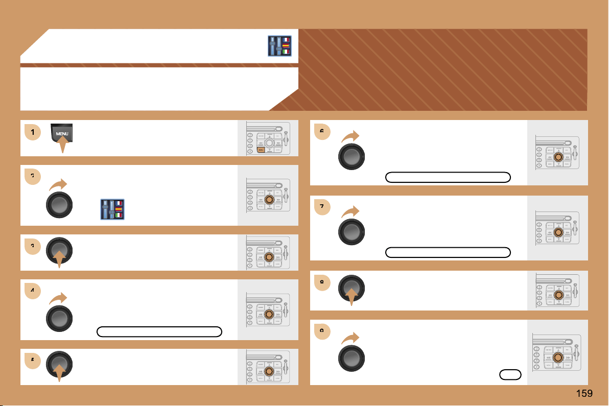
1
1
2
2
3
3
4
4
5
5
6
6
7
7
8
8
9
9
07 CONFIGURATION
ADJUSTING THE DATE AND TIME
Press the MENU button.
Turn the dial and select the
CONFIGURATION function.
Press the dial to confirm the selection.
Turn the dial and select the
DISPLAY CONFIGURATION function.
Press the dial to confirm the
selection.
Turn the dial and select the
ADJUST THE DATE AND TIME
function.
Adjust the parameters one by one
confirming by pressing the OK
button. Next select the OK tab on
the display then confirm.
DISPLAY CONFIGURATION
ADJUST THE DATE AND TIME
OK
Press the dial to confirm the selection.
Turn the dial and select the
INTERNATIONAL PARAMETERS
function then confirm.
INTERNATIONAL PARAMETERS
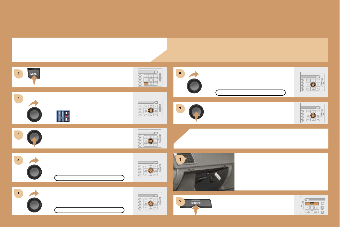
2
2
3
3
4
4
5
5
6
6
7
7
1
1
1
2
2
ACTIVATING THE AUXILIARY INPUT (AUX)
COLOUR DISPLAY DT
Press the MENU button.
Turn the dial and select the
CONFIGURATION function.
Press the dial to confirm the selection.
Turn the dial and select
the DISPLAY CONFIGURATION
function then confirm.
DISPLAY CONFIGURATION
Turn the dial and select the SOUND
function then confirm.
ACTIVATE AUX INPUT
SOUND
Turn the dial and select
the ACTIVATE AUX INPUT
function.
USING THE AUXILIARY INPUT (AUX)
CABLE NOT SUPPLIED
Press the SOURCE button several
times in succession and select AUX.
Connect the portable equipment
(MP3 player…) to the audio sockets
(white and red, RCA type) located
in the glove box.
Press the dial to confirm the selection.
The auxiliary input permits the connection of portable equipment
(MP3 player...).
160
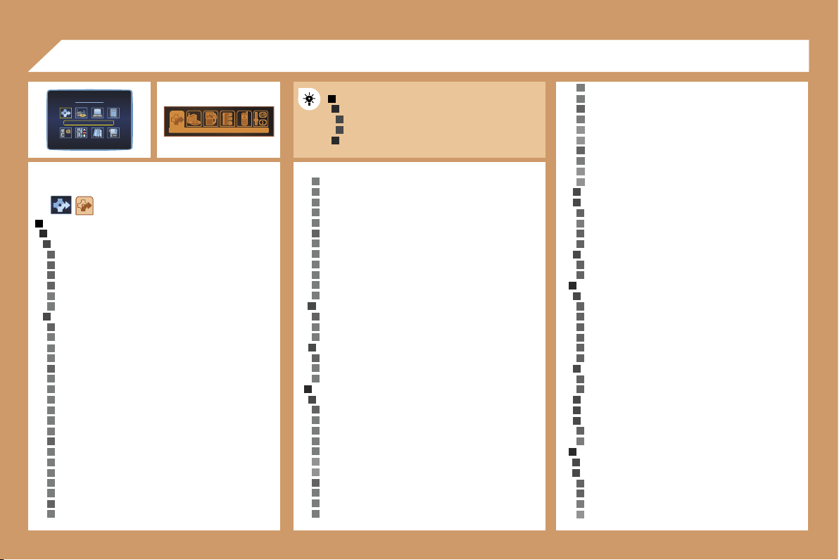
1
2
3
2
3
1
2
3
4
5
4
4
4
3
4
5
5
4
5
5
5
5
5
5
4
5
5
5
5
5
4
5
5
5
5
5
5
4
5
5
5
5
5
5
3
4
5
5
3
4
5
5
2
3
4
5
5
5
5
6
6
4
5
5
5
4
5
6
6
4
5
6
6
3
3
4
5
4
4
3
4
4
2
5
5
3
4
4
4
4
4
4
3
4
4
3
3
3
4
5
2
3
3
4
4
5
6
5
5
161
DT
MAIN FUNCTION
CHOICE A
Choice
A1
Choice A2
CHOICE B...
08 DISPLAY FLOW CHARTS
COMMON FLOW CHART
DISPLAYS DT AND CT
golf courses
skating rinks, bowling alleys
winter sports centres
parks & gardens
theme parks
transport & automobile
ports, airports
station, bus stations
automatic checks
vehicle hire
rest areas, parking
service stations, garages
directory
nav directory
town, street, n°
ok
previous destinations
list of destinations
town, street, n°
ok
STAGES AND ROUTE
add a stage
enter an address
town
street
junction n°
gps
longitude
latitude
choice of a service
administration & security
hotels, restaurants & businesses
culture, tourism & shows
sports centres & outdoor pursuits
transport & automobile
directory
nav directory
town, street, n°
ok
previous destinations
list of destinations
town, street, n°
ok
order/delete stages
divert route
divert route over 2 km
the best diversion possible is 3 km. continue?
range 1-50
ok
chosen destination
town, street, n°
change
GUIDANCE OPTION
define the calculation criteria
the fastest
the shortest
distance/time
with tolls
with ferry
traffic info
adjust speech synthesis
volume
activate/deactivate
activate/deactivate street names
description of the cd-rom
delete the previous destinations
do you want to delete the list of previous destinations?
yes/no
TMC TRAFFIC INFORMATION
consult the messages
filter the TMC traffic information
activate/deactivate the route filter
filter by event
traffic information
traffic information
NAVIGATION/TRAFFIC INFO
CHOICE OF DESTINATION
enter an address
town
street
junction n°
gps
longitude
latitude
choice of a service
administration & security
town halls, town centre
universities, colleges
hospitals
hotels, restaurants & businesses
hotels
restaurants
vinyards
business centres
supermarkets, shopping
craft centres
culture, tourism & shows
tourism, historical monuments
culture, museums & theatres
shows & exhibitions
casinos & nightlife
cinemas
sports centres & outdoor pursuits
sports centres, complexes
CT
6
6
6
6
5
5
3
4
2
5
4
5
5
4
3
6
6
6
4
5
1
2
2
2
2
1
2
3
3
4
4
4
4
4
4
2
3
3
3
2
3
5
5
5
5
6
6
5
6
7
6
6
5
3
4
3
4
3
4
5
5
2
3
4
3
3
4
4
2
3
4
4
1
2
3
4
6
6
7
6
6
6
6
4
3
4
4
4
4
1
2
3
2
3
3
3
4
2
3
4
5
6
5
4
5
3
4
4
4
3
4
4
4
5
5
5
5
5
3
3
3
3
162
TRIP COMPUTER
TRIP COMPUTER CONFIGURATION
enter distance to destination
0 km
select units
l/100 & km
mpg & miles
km/l & km
°c/°f
bar, psi
DIAGNOSTICS
warning log
equipment backup supply
gps coverage
STATUS OF FUNCTIONS
list of functions
road closures
road restrictions
road conditions
weather & visibility
urban information
parking
public transport
demonstrations
geographical filter
around the vehicle
around a place/select
filter radius 50 km
choice of TMC station
station name
next station
speech synthesis
volume
activate/deactivate
activate/deactivate presentation of messages
RESUME/STOP GUIDANCE
AUDIO FUNCTIONS
ACTIVATE/DEACTIVATE RDS ALTERNATIVE FREQUENCIES
ACTIVATE/DEACTIVATE REGIONAL MODE
ACTIVATE/DEACTIVATE RADIO TEXT INFO
ACTIVATE/DEACTIVATE CD DETAILS INFO
DIRECTORY
MANAGEMENT OF DIRECTORY FILES
consult or change a file
entire directory
name
voice recording
notes
address
town
street
n°
number
display
list of numbers
change
add
delete
e-mail
display
list of numbers
change
add
delete
add a file
description
delete a file
entire directory
delete all files
do you want to delete all of the files in the directory
(non sim)?
yes
no
CONFIGURATION OF THE DIRECTORY
select a directory
user xxxx
name a directory
select the starting directory
user xxx
last directory used
FILE TRANSFER
infrared exchange
send all files
send one file
receive by infrared
exchange with the sim card
send all files
send one file
receive all files
receive one file
TELEPHONE AND TELEMATIC SERVICES
CALL
calls log
dial
directory
voice mail
SERVICE
customer contact centre
PEUGEOT
assistance
PEUGEOT
mobile services
(if services available and/or activated)
messages received
list of v-cards
TELEPHONE FUNCTIONS
network
network search mode
automatic mode
manual mode
list of networks
networks available
list of networks
duration of calls
partial counter
total duration
zero reset
manage the pin code
activate
store the pin code
change the pin code
entering the pin code
old code
> new code
confirmation
>> correct
4
5
5
4
5
3
2
3
4
3
4
3
4
4
5
6
6
5
6
1
2
3
4
3
5
6
6
5
6
6
5
6
6
5
6
4
5
5
3
4
5
5
5
4
5
5
5
5
5
3
4
2
1
2
3
4
4
4
3
4
4
3
4
5
6
6
5
6
6
5
6
5
6
4
5
5
3
4
5
5
5
4
5
5
5
5
5
3
4
2
4
5
5
4
3
163
call options
delete the list of calls and sms
do you want to delete the list of calls and sms from the
equipment?
configure the calls
displaying of my number
automatic pick-up after 3 rings
ring options
for voice calls
volume
type of ring
for text messages (sms)
text message buzzer
voice call diversion n°
TEXT MESSAGES (SMS)
reading text messages received
list of text messages received
sending a text message
list of saved text messages
writing a text message
text message
message sent
delete the list of text messages
SPECIAL FEATURES OF CT DISPLAYS
CONFIGURATION
DISPLAY CONFIGURATION
adjust the brightness
sound
speech synthesis adjustment
volume of guidance instructions
volume
activate/deactivate
volume of other messages
volume
activate/deactivate
select a voice
male
female
speech synthesis
activate/deactivate
voice command adjustment
volume
activate/deactivate
international parameters
adjust the date & time
day, month, year
time, 12 h, 24 h, am/pm
adjusting the minutes on gps
select the units
l/100 & km
mpg & miles
km/l & km
°c/°f
bar, psi
choice of language
list of languages available
DEFINE THE VEHICLE PARAMETERS*
* The parameters vary according to vehicle
SPECIAL FEATURES OF DT DISPLAYS
CONFIGURATION
DISPLAY CONFIGURATION
select the colours
6 colours
night
automatic day/night
luminosity & brightness
luminosity
brightness
sound
speech synthesis adjustment
volume of guidance instructions
volume
activate/deactivate
volume of other messages
volume
activate/deactivate
select a voice
male/female
speech synthesis
activate/deactivate
voice command adjustment
volume
activate/deactivate
aux input
activate/deactivate
international parameters
adjust the date & time
day, month, year
time, 12 h, 24 h, am/pm
adjusting the minutes on gps
select the units
l/100 & km
mpg & miles
km/l & km
°c/°f
bar, psi
choice of language
list of languages available
DEFINE THE VEHICLE PARAMETERS*
2
3
4
2
3
2
3
2
4
4
3
4
4
4
4
4
4
3
4
4
4
4
4
3
4
4
4
4
4
4
3
4
4
4
4
4
1
3
2
4
4
2
3
2
4
4
3
3
3
1
164
Flow chart version 6.6
MAP
MOVE THE MAP
MAP ORIENTATION
north oriented map
vehicle oriented map
CENTRE AROUND VEHICLE
MAP DETAILS
administration & security
town halls, town centre
universities, colleges
hospitals
hotels, restaurants & businesses
hotels
restaurants
vinyards
business centres
supermarkets, shopping
craft centres
culture, tourism & shows
tourism, historical monuments
culture, museums & theatres
shows & exhibitions
casinos & nightlife
cinemas
sports centres & outdoor pursuits
sports centres, complexes
golf courses
skating rinks, bowling alleys
winter sports centres
parks & gardens
theme parks
transport & automobile
ports, airports
station, bus stations
automatic checks*
vehicle hire
rest areas, car parks
service stations, garages
STORE THE CURRENT POSITION
description
deleted
VIDEO
ACTIVATE VIDEO MODE
VIDEO PARAMETERS
display formats
16/9 (full screen)
4/3 (conventional)
adjust brightness
set colours
set contrast
* Function not available to date.
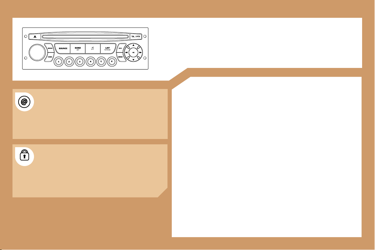
165
RD4
AUDIO EQUIPMENT
CONTENTS
• 01 First steps
pg. 166
• 02 General menu
pg. 167
• 03 Audio
pg. 168
• 04 Hands-free kit
pg. 170
• 05 Control short-cuts
pg. 171
• 06 Configuration
pg. 172
• 07 Display flow charts
pg. 173
The INFOTEC internet site provides additional
animated information on the RD4. It can be consulted
at the following address:
http://public.infotec.peugeot.com
Simple registration permits access and free
consultation of the handbook.
The RD4 audio equipment is coded in such a way that
it will only operate in your vehicle. If it is to be installed
in another vehicle, contact your PEUGEOT dealer for
configuration of the system.
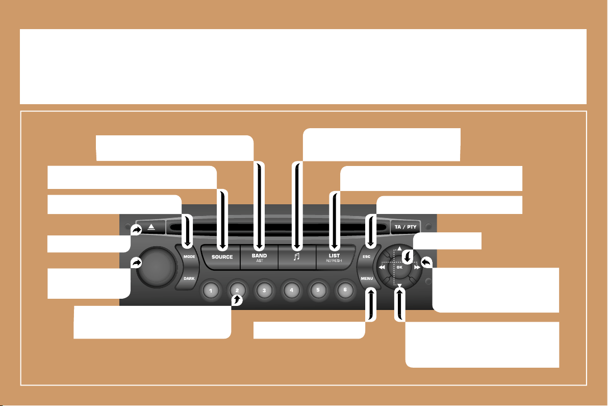
166
01 FIRST STEPS
On/Off and volume
adjustment.
CD eject.
Selection of the FM1, FM2, FMast and AM
wavebands.
Displaying of the general
menu.
- Selection of a lower/higher frequency.
- Selection of the previous/next CD.
- Selection of the previous/next MP3
directory.
- Automatic search for a lower/
higher frequency.
- Selection of previous/next CD or
MP3 track.
Selection of the source: radio, CD and CD
changer.
- Storing of a station.
- Selection of a stored radio station.
- Selection of a CD in the CD changer.
Setting the audio options:
Front/rear balance, left/right balance,
loudness, sound ambiences.
Displaying of the local stations, of the tracks on the
CD or of the MP3 directories.
Abandon current operation.
Selection of the screen display mode.
Confirmation.
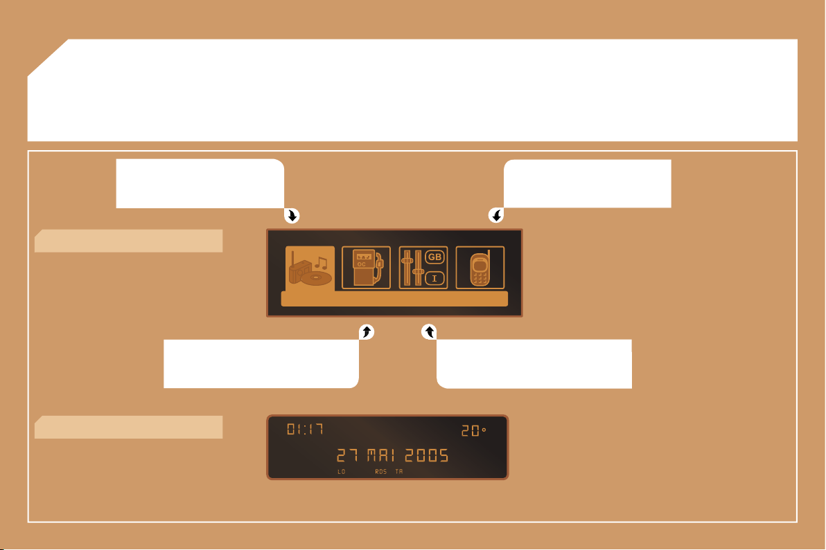
167
02 GENERAL MENU
AUDIO FUNCTION: radio, CD,
options.
TELEPHONE: hands-free kit,
matching, management of a
communication.
TRIP COMPUTER: distance entering,
warnings, status of functions.
> MONOCHROME DISPLAY C
PERSONALISATION-CONFIGURATION:
vehicle parameters, display, languages.
> MONOCHROME DISPLAY A
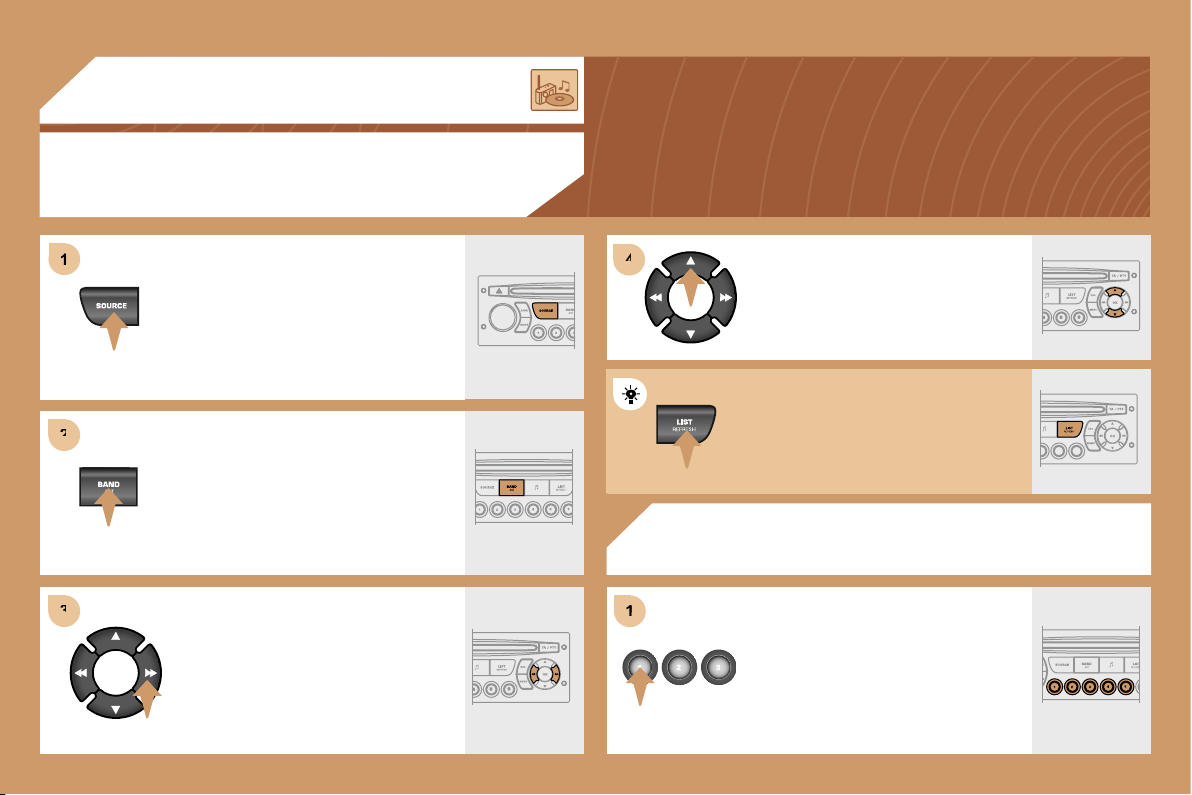
1
1
2
2
3
3
4
4
1
1
168
03 AUDIO
RADIO
SELECTING A STATION
RADIO
STORING A STATION
Press the SOURCE button several
times in succession and select the
radio.
Press the BAND AST button to select
a waveband: FM1, FM2, FMast, AM.
Briefly press one of the buttons to
carry out an automatic search of the
radio stations.
Press one of the buttons to carry out a
manual search of the radio stations.
Press one of the buttons on the
numeric keypad for more than
2 seconds to store the frequency of
the current station.
Press the LIST REFRESH button to
display the list of stations received
locally.
To update this list, press for more than
two seconds.
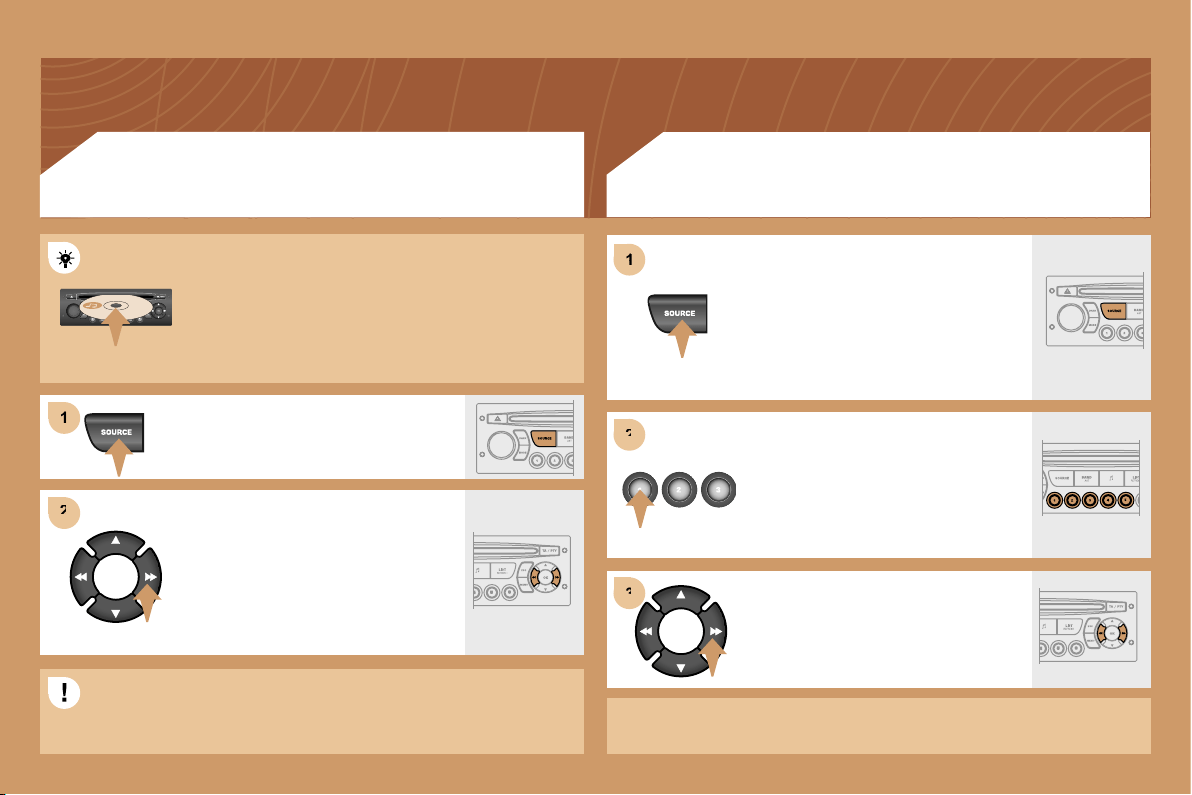
1
2
2
3
3
1
1
2
2
169
CD CHANGER
PLAYING A CD (NOT MP3 COMPATIBLE)
Insert one or more CDs in the
changer.
Press the SOURCE button several
times in succession and select CD
CHANGER.
Press one of the buttons on the
numeric keypad to select the
corresponding CD.
Press one of the buttons to select a
track on the CD.
Press and hold one of the buttons for
fast forwards or backwards play.
CD
PLAYING A CD OR AN MP3 COMPILATION*
Insert circular compact discs only. Some anti-pirating
systems, on original discs or CDs copied using a
personal recorder, may cause faults which are no
reflection on the quality of the original player.
Insert a CD or an MP3 compilation in the player, play
begins automatically.
If the player already contains a disc,
press the SOURCE button several
times in succession and select CD.
Press one of the buttons to select a
track on the CD.
Press the LIST REFRESH button to
display the list of tracks on the CD or
of the directories of the MP3
compilation.
The playing and displaying of an MP3 compilation may depend on
the recording programme and/or the parameter settings used. We
recommend use of the ISO 9660 recording standard.
* according to specification.

1
1
2
2
1
1
2
2
3
3
4
4
1
1
170
YES
YES
Press the end of the steering wheel stalk to accept
the call.
The services offered by the hands-free kit depend on the network,
the SIM card and the compatibility of the Bluetooth equipment used.
Consult your telephone’s manual and your operator to find out which
services are available to you. A list of mobile telephones which offer the
best range of services is available from the network. Contact a PEUGEOT
dealer.
MAKING A CALL
Press and hold the end of the steering wheel stalk
to access your directory.
To dial a number, use the keypad on your telephone.
04 HANDS-FREE KIT
MATCHING A TELEPHONE
DISPLAY C
For safety reasons and because they require prolonged attention
on the part of the driver, the operations for matching of the
Bluetooth mobile telephone with the RD4 hands-free kit must be
carried out with the vehicle stationary and the ignition on.
Activate the telephone’s Bluetooth function and
carry out a search of the Bluetooth accessories
present for the telephone.
Select the accessory which corresponds to
the name of the vehicle, a superimposed
configuration display appears on the multi-function
display.
Enter the vehicle’s authentication code (=1234).
Depending on the telephone, you may be asked
to enter this code before the superimposed
configuration display appears.
Select the YES tab on the display
using the buttons then confirm by
pressing OK.
RECEIVING A CALL
An incoming call is announced by a ring and a superimposed
display on the multi-function display.
Select the YES tab on the display
using the buttons and confirm by
pressing OK.
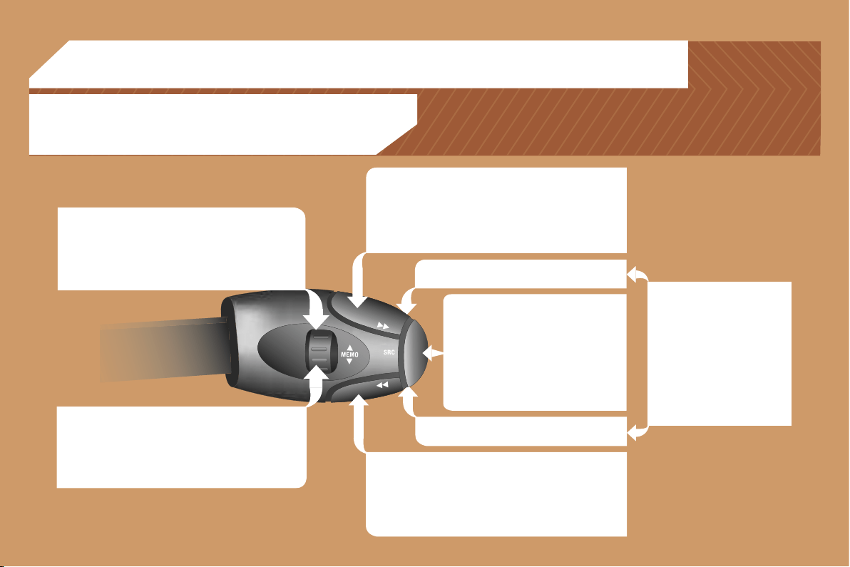
171
RADIO: selection of the next stored station.
CD CHANGER: selection of the next CD.
Selection of the next item on a menu.
MP3: selection of the next directory.
RADIO: selection of the previous stored station.
CD CHANGER: selection of the previous CD.
Selection of the previous item on a menu.
MP3: selection of the previous directory.
RADIO: automatic search for a higher frequency.
CD/CD CHANGER/MP3: selection of the next track.
Continuous press: fast forwards play.
Selection of the previous item.
RADIO: automatic search for a lower frequency.
CD/CD CHANGER/MP3: selection of the previous track.
Continuous press: fast backwards play.
Selection of the next item.
Volume increase.
Volume decrease.
05 CONTROL SHORT-CUTS
Mute: by pressing the volume
increase and decrease
buttons simultaneously.
The sound is restored by
pressing one of the two
volume buttons.
- Change of sound source.
- Confirmation of a selection.
- Pick up/Hang up the telephone.
- Press for more than 2 seconds:
access to the telephone menu.
STEERING WHEEL CONTROLS
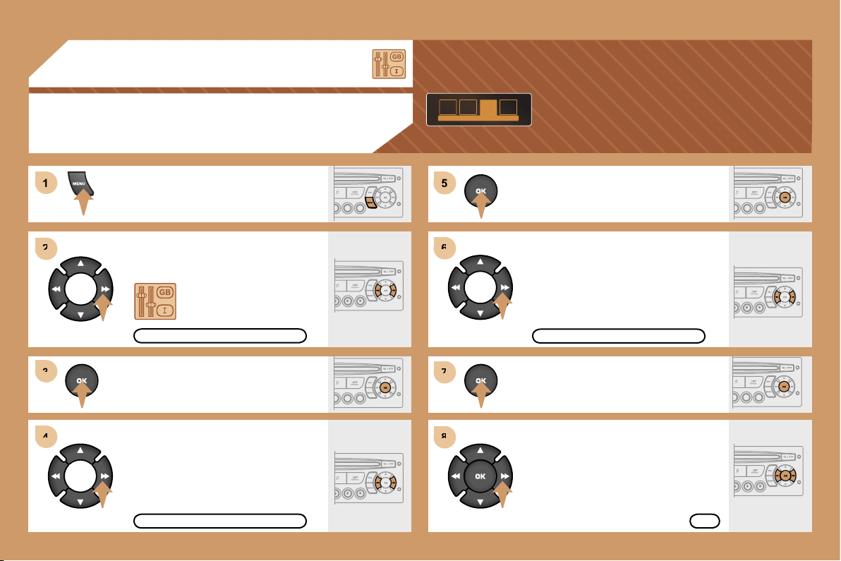
5
6
6
7
7
8
8
1
1
2
2
3
3
4
4
172
06 CONFIGURATION
ADJUSTING THE DATE AND TIME
DISPLAY C
Press the MENU button.
Using the arrows, select
the PERSONALISATION
CONFIGURATION function.
Press to confirm the selection.
Using the arrows, select
the DISPLAY CONFIGURATION
function.
Press to confirm the selection.
Press to confirm the selection.
Using the arrows, select
the ADJUST DATE AND TIME
function.
Adjust the parameters one by one
confirming by pressing the OK button.
Next select the OK tab on the display
then confirm.
DISPLAY CONFIGURATION
ADJUST DATE AND TIME
OK
PERSONALISATION CONFIGURATION
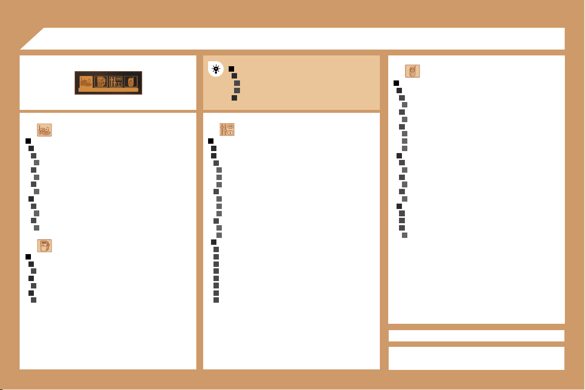
1
2
3
2
3
1
2
2
4
3
4
4
4
3
4
4
4
3
4
1
2
3
4
3
4
4
2
3
4
3
4
1
2
3
2
3
2
3
1
2
3
4
3
4
3
4
4
4
2
3
4
3
4
3
4
2
3
3
3
4
2
3
3
3
3
3
3
3
3
3
173
AUDIO FUNCTIONS
FM BAND PREFERENCES
alternative frequencies (RDS)
activate/deactivate
regional mode (REG)
activate/deactivate
radio-text information (RDTXT)
activate/deactivate
AUDIO CD PREFERENCES
cd changer repeat (RPT)
activate/deactivate
track random play (RDM)
activate/deactivate
TELEPHONE
CONSULTING DIRECTORIES**
telephone directory
directory list
call log
call list
services directory
customer contact centre
breakdown call
emergency call
CONFIGURATION
deletion of a match
list of matches
consulting matches
list of matches
choice of a mobile to connect
list of mobiles
MANAGEMENT OF A COMMUNICATION
switch**
terminate the current call
secret mode
activate/deactivate
07 DISPLAY FLOW CHART
monochrome C
PERSONALISATION-CONFIGURATION
DEFINE THE VEHICLE PARAMETERS*
DISPLAY CONFIGURATION
video brightness adjustment
normal video
inverse video
brightness (- +) adjustment
date and time adjustment
day/month/year adjustment
hour/minute adjustment
choice of 12 h/24 h mode
choice of units
l/100 km - mpg - km/l
°Celsius/°Fahrenheit
CHOICE OF LANGUAGE
deutsch
english
espanol
français
italiano
nederlands
portugues
portugues-brasil
MAIN FUNCTION
CHOICE A
Choice A1
Choice A2
CHOICE B...
TRIP COMPUTER
ENTER DISTANCE TO DESTINATION
distance: x km
WARNING LOG
diagnostics
STATUS OF FUNCTIONS
functions activated or deactivated
* The parameters vary according to vehicle.
** According to compatibility of Bluetooth telephone
and service contract.
C
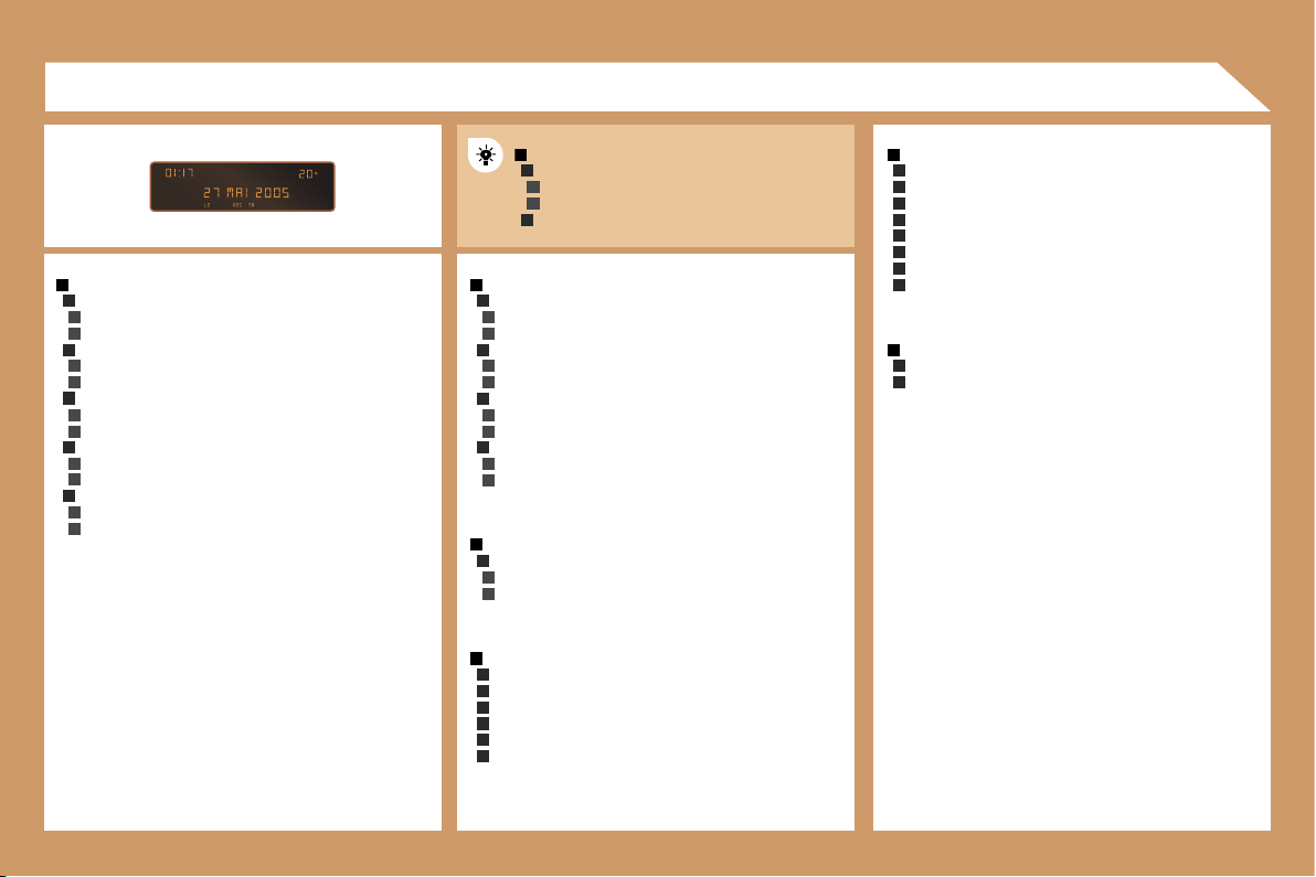
1
2
3
3
2
3
3
2
3
3
2
3
3
2
3
3
1
2
3
3
2
3
3
1
2
3
3
1
2
2
2
2
2
2
1
2
2
2
2
2
2
2
2
1
2
2
1
2
3
2
3
2
3
3
2
3
3
174
RADIO-CD
RDS SEARCH
active
inactive
REG MODE
active
inactive
INTROSCAN
active
inactive
CD REPEAT
active
inactive
RANDOM PLAY
active
inactive
VEHICLE CONFIG
REV WIPE ACT
active
inactive
AUTO LAMPS
active
inactive
GUIDE LAMPS
active
inactive
PARKING ASSIST
active
inactive
LANGUAGES
FRANCAIS
ITALIANO
NEDERLANDS
PORTUGUES
PORTUGUES-BRASIL
DEUTSCH
ENGLISH
ESPANOL
OPTIONS
ABANDON/CONSULT LIST OF FAULTS
functions activated (or not)
warning messages
DISPLAY ADJUST
YEAR
MONTH
DAY
HOUR
MINUTES
12 H/24 H MODE
UNITS
TEMPERATURE: °CELSIUS/°FAHRENHEIT
FUEL CONSUMPTION: KM/L - L/100 - MPG
07 DISPLAY FLOW CHART
monochrome A
MAIN FUNCTION
CHOICE A
Choice A1
Choice A2
CHOICE B...
A
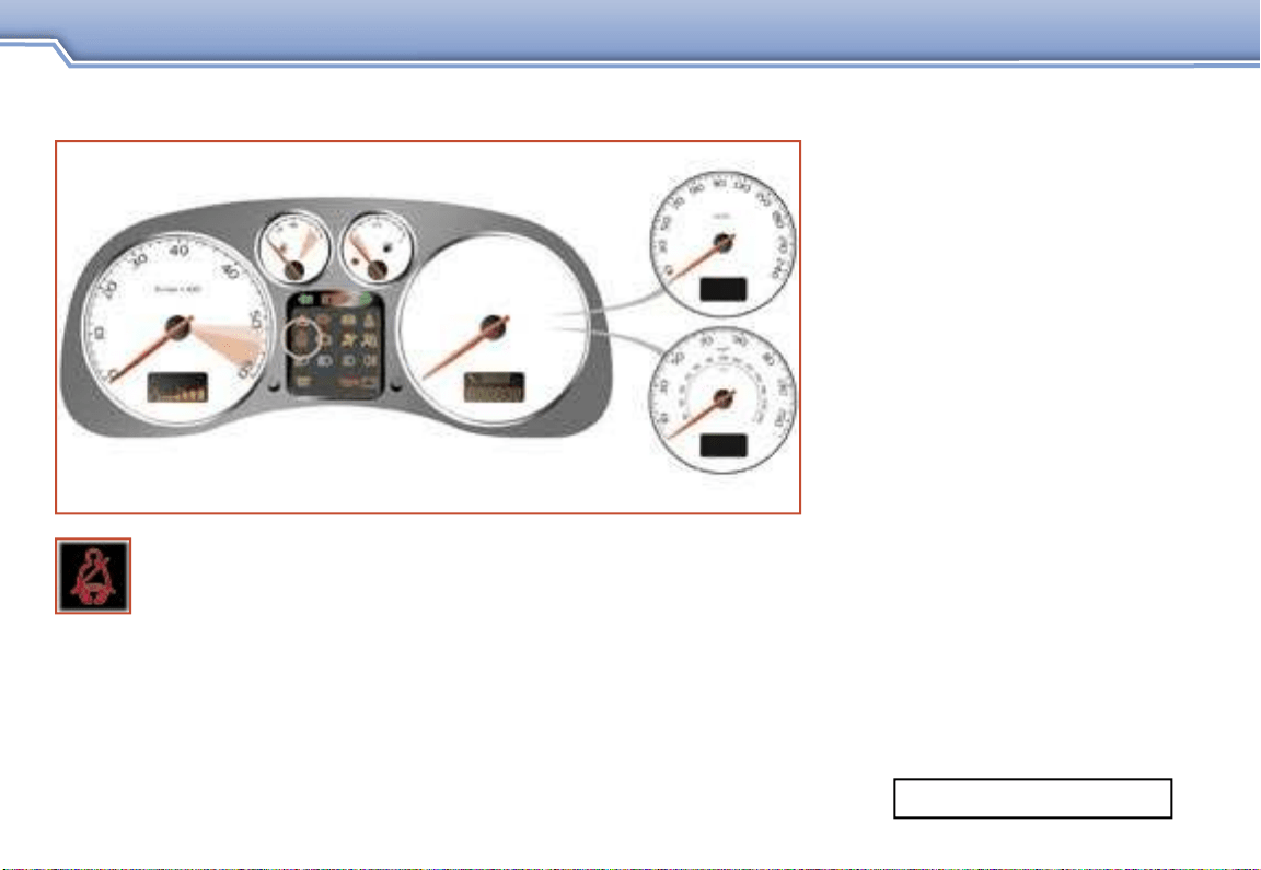
SUPPLEMENT TO THE 307 HANDBOOK
SAFETY
SEAT BELT NOT FASTENED WARNING LIGHT
Printed in the EU
20.0 09-06 English
The warning light comes on each time the ignition is switched on.
The warning light remains on until the driver fastens his seat belt.
From around 12 mph (20 km/h) the warning light flashes for
approximately two minutes accompanied by an audible signal
which increases in volume. Once these two minutes have elapsed, the
warning light remains on until the driver fastens his seat belt.
AN. 06307. A030
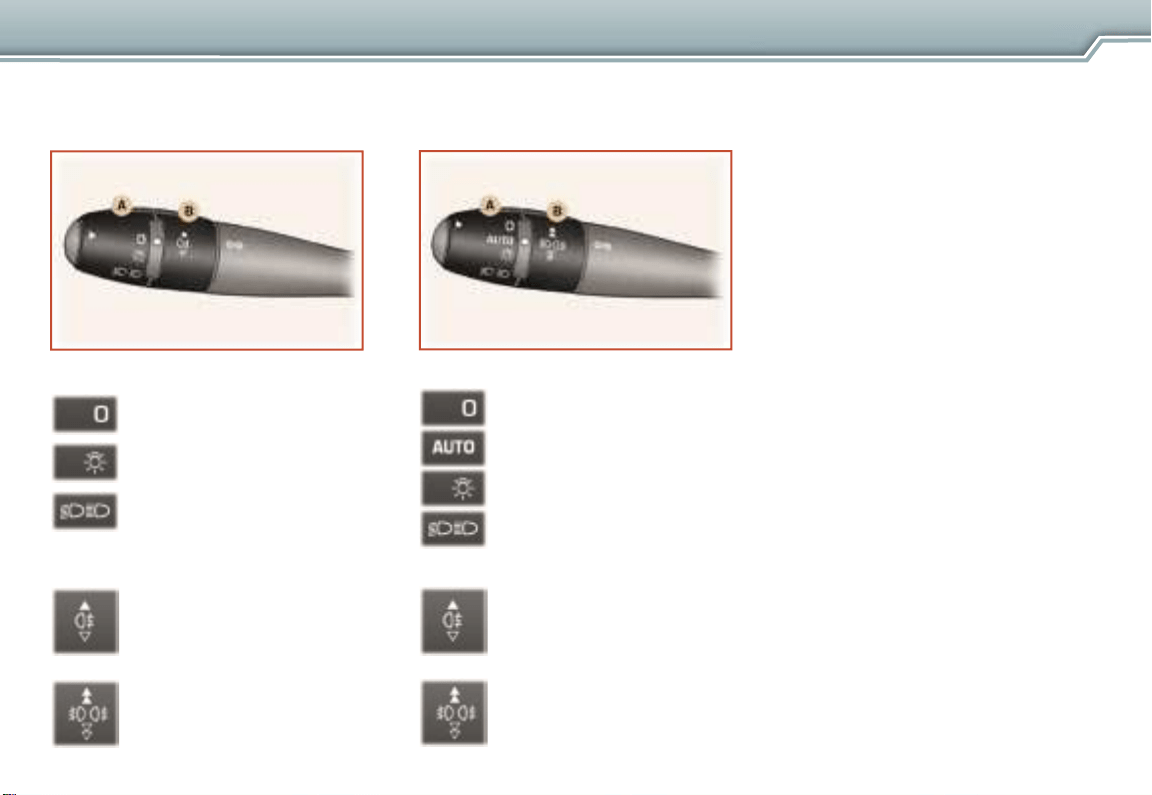
LIGHTS STALK
SUPPLEMENT TO THE 307 HANDBOOK
VISIBILITY
Stalk with AUTO lighting
Stalk without AUTO lighting
Ring A
Lights off.
Side lights.
Dipped headlamps /
main beam headlamps.
Ring B
Rear fog lamps.
or
Front and rear fog lamps.
Ring A
Lights off.
Automatic switching on
of the lights.
Side lights.
Ring B
Rear fog lamps.
or
Front and rear fog lamps.
Dipped headlamps /
main beam headlamps.
Automatic lighting
The side lights and dipped
headlamps come on automatically,
without any action on the part
of the driver, when a low level of
exterior light is detected (sensor
behind the interior mirror) or when
the wipers are switched on.
When the light returns to a
sufficient level or the wipers
are switched off, the lights are
switched off automatically.
Activation
Turn ring A to the "AUTO"
position. The automatic lighting
is accompanied by a message
on the multifunction display.
Deactivation
Turn ring A to a position other
than the "AUTO" position.
Deactivation is accompanied by
a message on the multifunction
display.