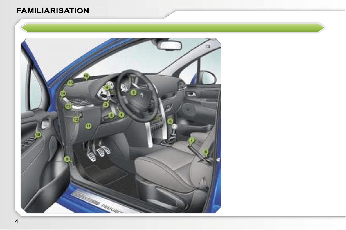
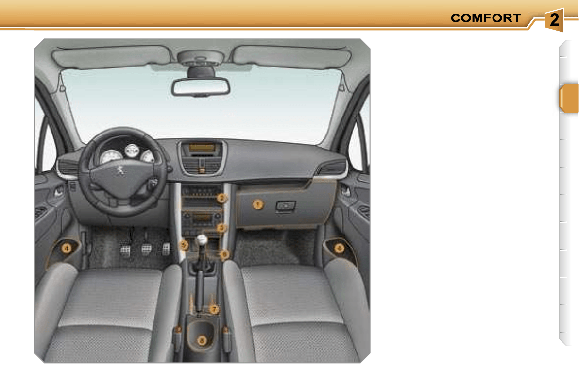
INSTRUMENTS AND CONTROLS
1.
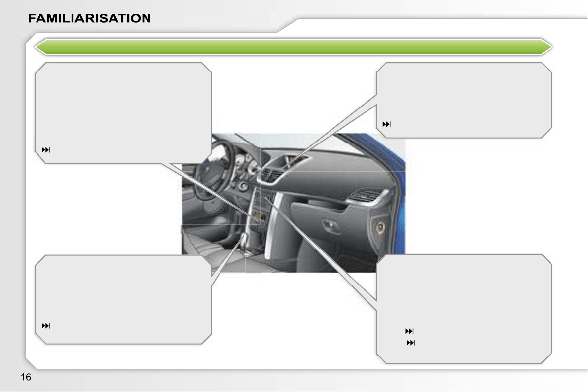
Cruise control/speed limiter switch.
2.
Steering wheel adjustments
control.
3.
Lights and direction indicators
controls.
4.
Instrument panel.
5.
Driver’s air bag.
Horn.
6.
Gear lever.
7.
Handbrake.
8.
Panoramic roof shutter control (SW).
9.
Bonnet release control.
10.
Exterior mirror controls.
Electric window controls.
Rear electric windows deactivation
control.
11.
Fuse box.
12.
Headlamp height adjustment.
13.
Side adjustable and closing vent.
14.
Front door window de-icing vent.
15.
Speaker (tweeter).
16.
Windscreen de-icing vent.
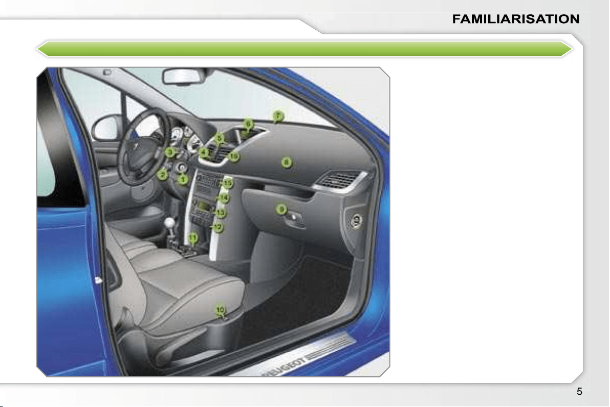
INSTRUMENTS AND CONTROLS
1.
Steering lock and ignition.
2.
Audio equipment steering wheel
control.
3.
Wipers/wash-wipe/trip computer
controls.
4.
Hazard warning lights switch.
5.
Fragrance diffuser.
6.
Multifunction display.
Seat belt fastening status warning
lights.
7.
Sunshine sensor.
8.
Passenger air bag.
9.
Glove box/Passenger air bag
disarming/Audio/video sockets.
10.
Heated seat control.
11.
Front ashtray/Lighter.
12.
Dynamic stability control (ESP/
ASR) button.
Rear parking assistance button.
Central locking button.
Alarm button.
Electric child lock button.
13.
Heating/air conditioning controls.
14.
CD changer.
15.
Audio RD4 or RT3 GPS audio/
telephone.
16.
Central adjustable and closing
vents.
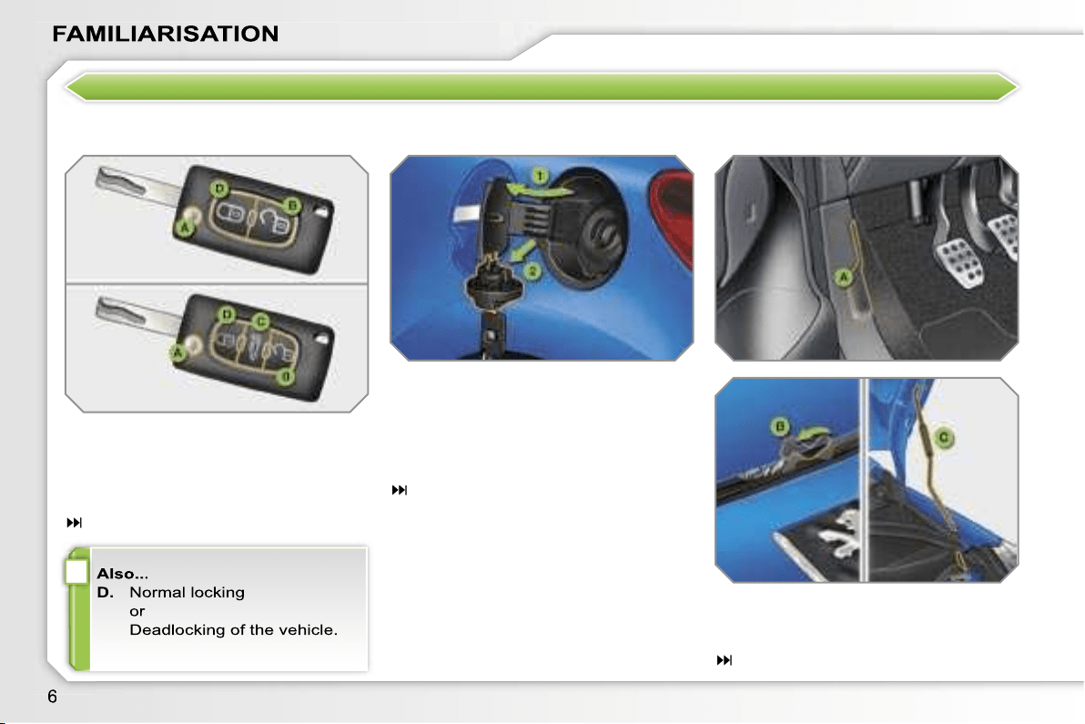
i
OPEN
Remote control key
A.
Unfolding/Folding the key.
B.
Unlocking the vehicle.
C.
Unlocking and partially opening
the rear screen (SW).
70
Fuel tank
1.
Opening the fuel filler flap.
2.
Opening and hooking the fuel filler
cap.
Capacity of the tank: approximately
50
litres.
84
Bonnet
A.
Interior control.
B.
Exterior control.
C.
Bonnet strut.
129
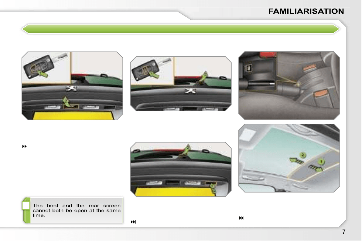
i
OPEN
Boot (SW)
1.
Unlocking the vehicle.
2.
Opening the boot.
81
Rear screen (SW)
Vehicle locked
Panoramic roof (SW)
1.
Unlocking and partially opening
the rear screen.
2.
Opening the rear screen.
1.
Opening the shutter.
2.
Closing the shutter.
83
81
1.
Partially opening the rear screen.
2.
Opening the rear screen.
Vehicle unlocked
i
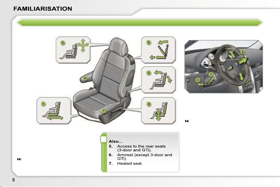
SITTING COMFORTABLY
Front seat adjustment Steering wheel adjustment
1.
Forwards-backwards adjustment.
2.
Height adjustment.
3.
Seat back angle adjustment.
4.
Head restraint height and angle
adjustment (except GTi).
54
1.
Unlocking the control.
2.
Height and depth adjustment.
3.
Locking the control.
61
i
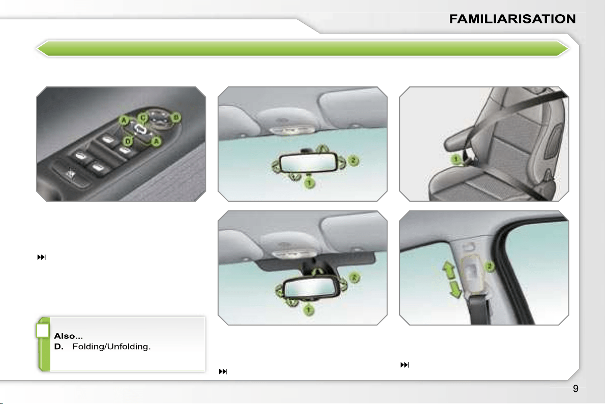
SITTING COMFORTABLY
Exterior mirrors adjustment
A.
Selecting the mirror.
B.
Adjusting the position of the mirror.
C.
De-selecting the mirror.
59
Interior mirror adjustment
1.
Selecting the "day" position of the
mirror.
2.
Directing the mirror.
60
Front seat belt
1.
Fastening.
2.
Height adjustment.
108
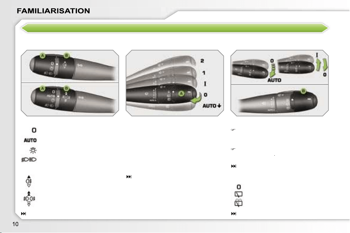
SEEING CLEARLY
Lights
Ring A
Switching on "AUTO" mode
Push the lever downwards and re-
lease it.
Ring B
Lever A: windscreen wipers
2.
Fast wipe.
1.
Normal wipe.
I.
Intermittent wipe.
0.
Park.
AUTO
Automatic wiping or single
wipe.
Wash-wipe: pull the lever towards you.
89
Wipers
Switching off "AUTO" mode
Push the lever upwards and return it
to position
"0"
.
91
Ring B: rear wiper
85
90
Lights off.
Side lights.
Dipped/main beam headlamps.
Rear fog lamps.
or
Front and rear fog lamps.
Park.
Intermittent wipe.
Wash-wipe.
Automatic lighting.
–
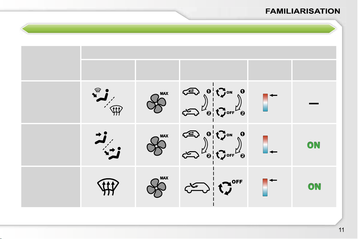
VENTILATION
Advice on interior settings
I require...
Heating or Manual air conditioning
Air distribution
Air flow
Air recirculation/
Exterior air intake
Temperature
Manual A/C
HEAT
COOL
DEMISTING
DE-ICING
Automatic air conditioning:
use of the fully automatic mode by pressing the
"AUTO"
button is preferable.
MONITORING
Instrument panel Controls bar
A.
With the ignition on, the fuel gauge
needle should rise.
B.
With the engine running, the
associated low level warning light
should switch off.
C.
With the ignition on, the oil level
indicator should display
"OIL OK"
for a few seconds.
If the levels are not correct, top up the
level which is low.
22
Lighting of the indicator light indicates
the status of the corresponding function.
A.
Deactivation of the ESP/ASR
system.
107
B.
Deactivation of the rear parking
assistance.
126
C.
Central locking.
70
D.
Deactivation of the interior
protection alarm.
74
E.
Activation of the electric child
lock*.
103
1.
With the ignition on, the orange
and red warning lights come on.
2.
With the engine running, these
warning lights should switch off.
If a warning light remains on, refer to
the page concerned.
23
Warning lights
* Except 3-door and GTi.
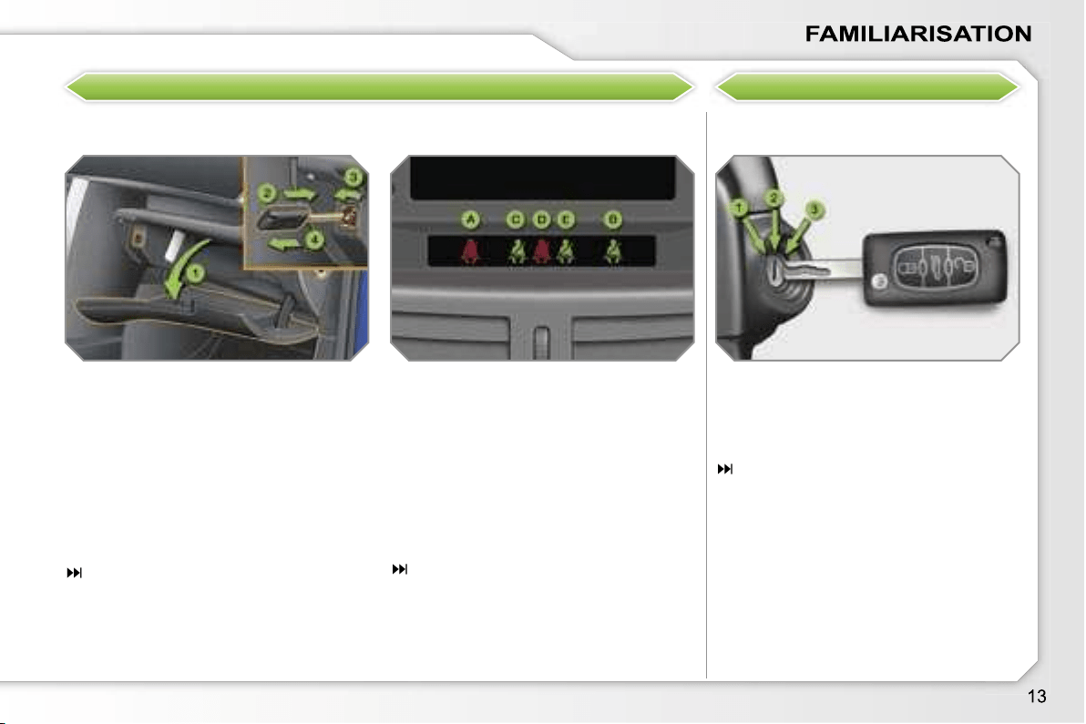
KEEPING YOUR PASSENGERS SAFE
Front passenger air bag Ignition switch
1.
Open the glove box.
2.
Insert the key.
3.
Select position:
"ON"
(activation), with front pas-
senger or "forwards facing" child
seat,
"OFF"
(deactivation), with "rear
facing" child seat.
4.
Remove the key keeping the
switch in this position.
111
1.
Stop
position.
2.
Ignition
position.
3.
Starting
position.
72
A.
Front left seat belt not fastened or
unfastened warning light lit in red.
B.
Front right seat belt fastened
indicator light lit in green.
C.
Rear left seat belt fastened
indicator light lit in green.
D.
Rear centre seat belt unfastened
indicator light lit in red*.
E.
Rear right seat belt fastened
indicator light lit in green.
108
Front and rear seat belts
START
* Except GTi.
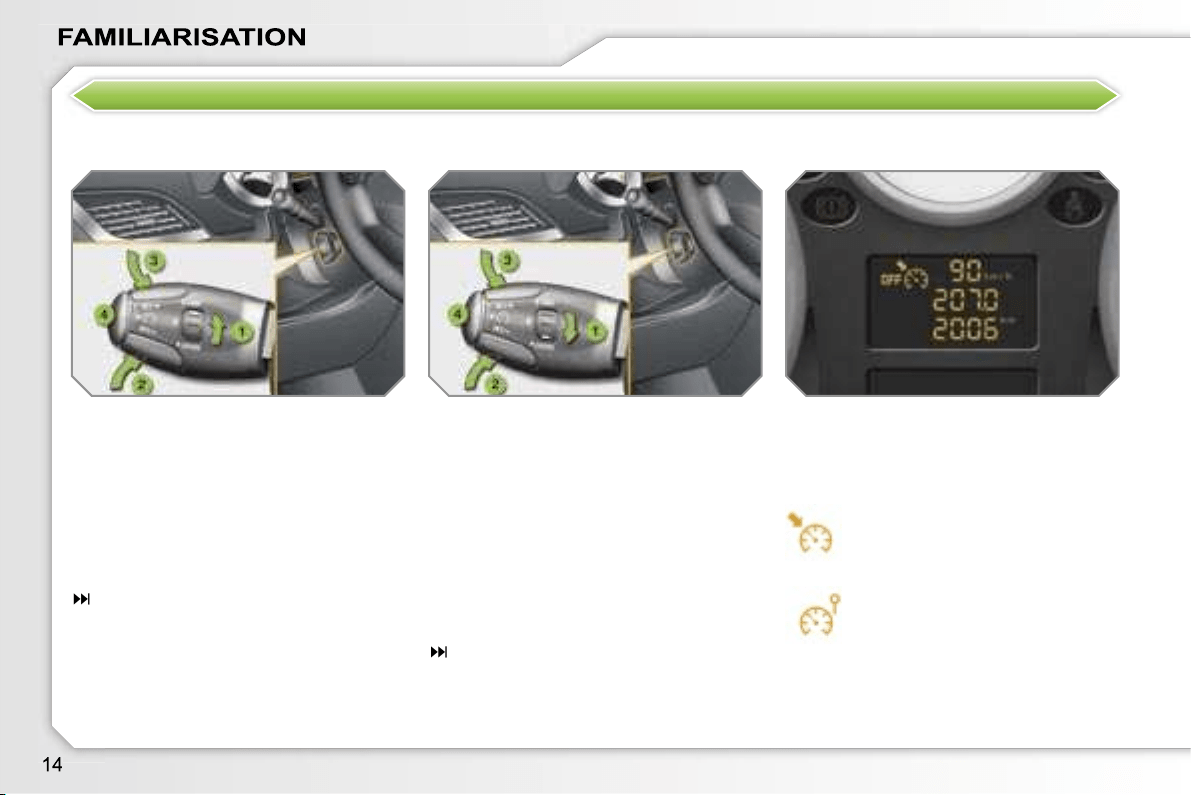
DRIVING SAFELY
Speed limiter Instrument panel display
1.
Selecting/Switching off speed
limiter mode.
2.
Decrease the programmed value.
3.
Increase the programmed value.
4.
Speed limiter on/off.
The values must be set with the engine
running.
122
The cruise control or speed limiter mode
appears on the instrument panel when
it is selected.
1.
Selecting/Switching off cruise
control mode.
2.
Decrease the programmed value.
3.
Increase the programmed value.
4.
Cruise control on/off.
In order to be programmed or activated,
the vehicle speed must be higher than
25 mph (40 km/h), with at least fourth
gear engaged on the manual gearbox
(second gear on the automatic gear-
box).
124
Cruise control
Cruise control
Speed limiter
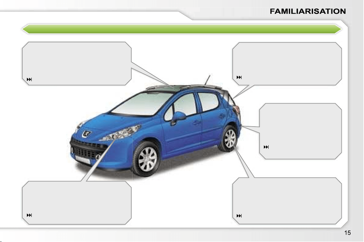
EXTERIOR FEATURES
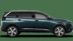
Panoramic roof
This extensively glazed roof provides
incomparable visibility and light in the
passenger compartment.
83
Static directional lighting
This additional lighting automatically pro-
vides extended visibility when turning.
88
Opening rear screen (SW)
This equipment permits easy access to
the luggage compartment without hav-
ing to open the tailgate.
81
Tyre under-inflation detection
This equipment monitors the pressure
in each tyre and warns you if a puncture
or deflation occurs.
105
Rear parking
assistance
This equipment provides a
warning when reversing by
detecting obstacles located
behind the vehicle.
126
INTERIOR FEATURES
Dual zone automatic air
conditioning
This equipment permits the setting of a
different level of comfort for the driver
and front passenger. It then automati-
cally controls this level in relation to the
exterior climatic conditions.
51
"2 Tronic" gearbox*
This equipment provides perfect driving
by combining a fully automatic mode, a
manual mode and an auto-sequential
mode which unites the advantages of
the other two modes.
116
Fragrance diffuser
This fragrance diffuser diffuses the per-
fume that you have selected throughout
the passenger compartment by means
of its location in the ventilation system.
53
Audio and communication
systems
This equipment benefits from the latest
technology: MP3 compatible audio
RD4, Bluetooth hands-free kit, RT3
audio/telephone with navigation (except
SW), JBL audio system.
RT3
175
RD4
197
* During the year.
22
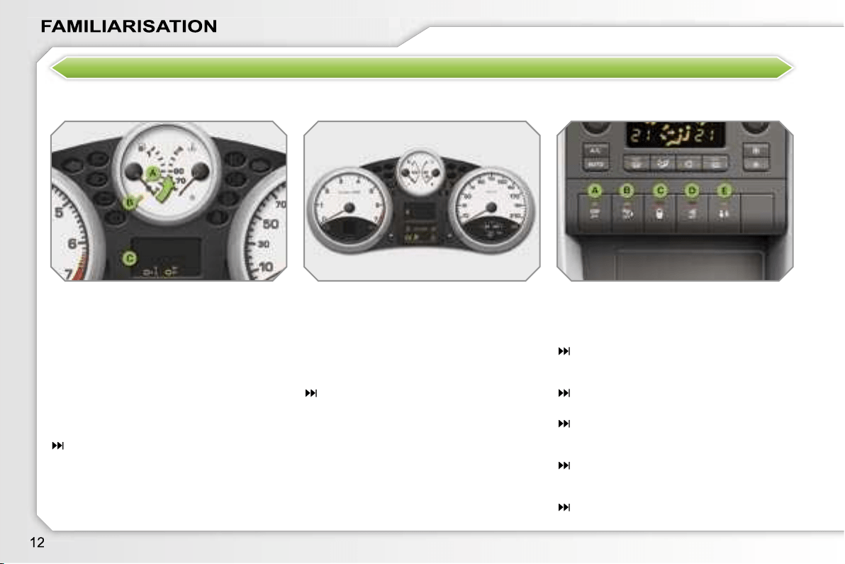
PETROL - DIESEL MANUAL GEARBOX, "2 TRONIC" GEARBOX
OR AUTOMATIC GEARBOX INSTRUMENT PANELS
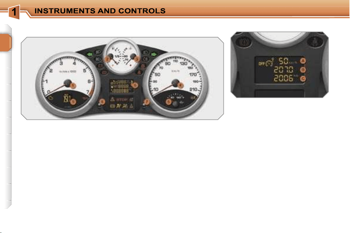
Panel which groups together the vehi-
cle operation dials and indicator lights.
5.
Oil temperature.
Indicates the temperature of the oil
in the engine (°Celsius).
6.
Display.
7.
Display zero reset button.
Resets the selected function to
zero (trip distance recorder or
service indicator).
8.
Instrument panel lighting
button.
Adjusts the brightness of the
lighting of the instruments and
controls.
9.
"2 Tronic" gearbox or automatic
gearbox.
Indicates the programme selected
and the gear engaged.
Dials
1.
Rev counter.
Indicates the speed of rotation of
the engine (x 1 000 rpm).
2.
Fuel gauge.
Indicates the quantity of fuel
remaining in the tank.
3.
Cooling temperature.
Indicates the temperature of the
engine coolant (°Celsius).
4.
Speedometer.
Indicates the current speed of the
moving vehicle (km/h or mph).
A.
Speed limiter
or
Cruise control.
(km/h or mph)
B.
Trip distance recorder.
(km or miles)
C.
Service indicator.
(km or miles) then,
Engine oil level indicator.
then
Distance recorder.
(km or miles)
These three functions are
displayed in succession when the
ignition is switched on.
For further information, refer to the sec-
tion which corresponds to the function
and to the display associated with it.
Display
!
23
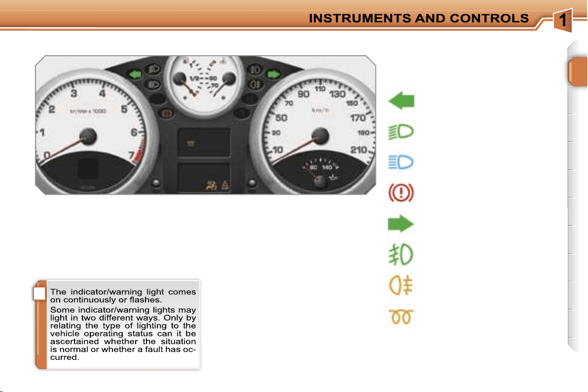
Indicator and warning lights
Visual indicators which inform the driv-
er when a system comes into opera-
tion (operation or deactivation indicator
lights) or of the occurrence of a fault
(warning light).
Associated warnings
The lighting of certain indicator/warning
lights may be accompanied by an audi-
ble signal and a message on the multi-
function display.
Operation indicator lights
The lighting of one of the following indi-
cator lights confirms that the correspond-
ing system has come into operation.
Left-hand direction
indicator.
Handbrake applied.
Right-hand direction indicator.
Main beam headlamps.
Dipped headlamps.
Diesel engine pre-heating.
Wait until this switches off be-
fore operating the starter.
Front fog lamps.
Rear fog lamps.
When the ignition is switched on
The warning lights come on for a few
seconds when the vehicle ignition is
switched on.
When the engine is started, these warn-
ing lights should switch off.
If they remain on, before moving off,
consult the text relating to the warning
light concerned.
24
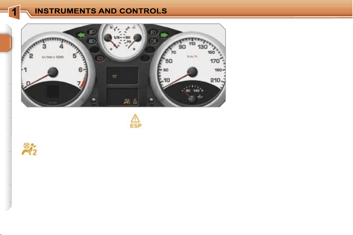
Deactivation indicator lights
The lighting of one of the following in-
dicator lights confirms that the corre-
sponding system has been switched off
intentionally.
Passenger air bag system
disarmed.
The passenger air bag system
is activated automatically when
the vehicle is started.
A special switch, located in the
glove box, permits the disarming of this
system. This is confirmed by continu-
ous lighting of this indicator light.
Deactivation of the dynamic
stability control (ESP).
The ESP system is activated automati-
cally when the vehicle is started.
A special button, located in the centre
of the fascia, permits the deactivation of
this system. This is confirmed by con-
tinuous lighting of this indicator light and
of the indicator light on the button.
!
25
When the engine is running or the vehi-
cle is moving, the lighting of one of the
following warning lights indicates the
occurrence of a fault which requires ac-
tion on the part of the driver.
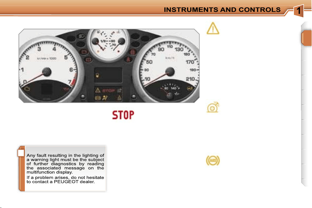
Centralised alert.
Lighting of the centralised alert
is associated with the lighting
of another warning light:
- punctured wheel,
- braking,
- engine oil pressure,
- coolant temperature.
It is imperative that the vehicle is
stopped as soon as it is safe to do so.
Service.
Lighting of the service warning
light indicates the occurrence of
a problem in one of the systems
which does not have a specific
warning light.
To identify the problem, consult the
message on the multifunction display.
After checking:
- the remote control battery,
- the engine oil level,
- the screenwash level,
for other cases, contact a PEUGEOT
dealer.
Punctured tyre.
The lighting of this warning light
indicates that one or more tyres
are punctured. It is imperative
that the vehicle is stopped as soon as it
is safe to do so.
Change the damaged wheel and have it
repaired by a PEUGEOT dealer.
Anti-lock braking system
(ABS).
The lighting of this warning light
indicates the occurrence of a
fault in the anti-lock braking
system.
However, this does not prevent the op-
eration of the vehicle’s assisted brak-
ing.
Warning lights
26
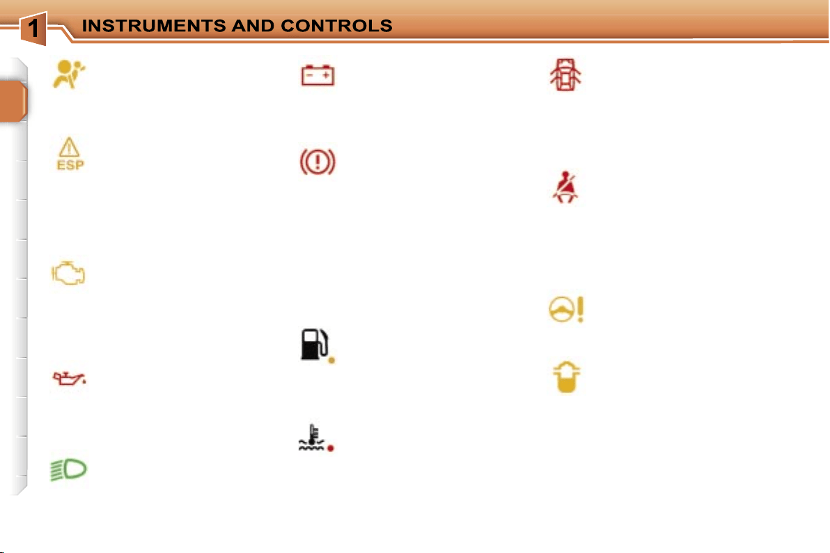
Air bags.
The lighting of this warning
light indicates the occurrence
of a fault in one of the air bags
(front, side or curtain) or pre-tensioning
seat belt systems.
Dynamic stability control
(ESP).
The ESP system is activated auto-
matically when the vehicle is started.
Unless the system has been deactivat-
ed, continuous lighting of this warning
light and flashing of the indicator light
on the button indicate the occurrence of
a fault in this system.
Engine autodiagnostics
system.
The lighting of this warning light
indicates the occurrence of a
fault in the engine management system.
Flashing of this warning light indicates
the occurrence of a fault in the emission
control system.
Engine oil pressure.
The lighting of this warning light
indicates the occurrence of a
fault in the engine lubrication
circuit. It is imperative that the vehicle is
stopped as soon as it is safe to do so.
Battery charge.
The lighting of this warning light
indicates the occurrence of a
fault in the battery charging cir-
cuit (dirty or loose terminals, slack or
cut alternator belt, ...).
Braking.
The lighting of this warning light
indicates the occurrence of a fault
in one of the braking systems:
- significant drop in the level in the cir-
cuit,
- electronic brake force distribution
(EBFD) faulty (if lit at the same time
as the ABS warning light).
It is imperative that the vehicle is
stopped as soon as it is safe to do so.
If the vehicle is moving, check that the
handbrake has been released fully.
Low fuel level.
The lighting of this warning light indi-
cates that there is enough fuel left to
drive approximately 30 miles (50 km).
The capacity of the fuel tank is approxi-
mately 50 litres.
Maximum coolant
temperature.
The lighting of this warning light
indicates an excessively high
temperature in the cooling system. It is
imperative that the vehicle is stopped
as soon as it is safe to do so.
Door open.
A door, the boot or the bonnet
is still open:
- if the speed is below 6 mph (10 km/h),
this warning light comes on continuously,
- if the speed is above 6 mph (10 km/h),
this warning light comes on continuous-
ly, accompanied by an audible signal.
Seat belt not fastened/
unfastened.
The lighting of this warning light
indicates that the driver* and/or
the front passenger has not fastened
his seat belt or has unfastened it.
It also indicates that one or more rear
passengers have unfastened their seat
belt.
Power steering.
The lighting of this warning light
indicates the occurrence of a fault
in the electric power steering.
Presence of water in diesel*.
The lighting of this warning light
indicates the presence of water
in the diesel filter.
There is a risk of damage to the
injection system on Diesel engines.
Directional headlamps.
Flashing of this warning light
indicates the occurrence of a
fault in the directional head-
lamps system.
* According to country.
i
27
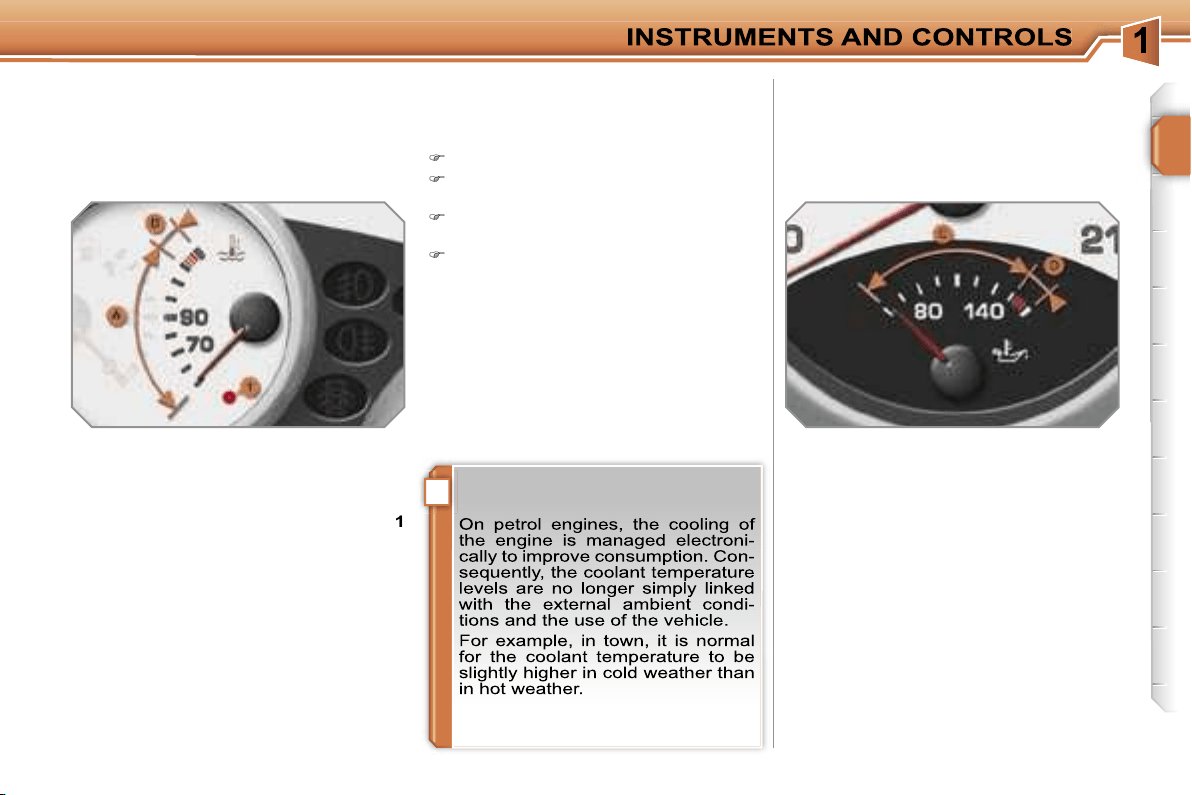
Coolant temperature
indicator
System which informs the driver of the
changes in the temperature of the en-
gine coolant while driving.
With the engine running, when the nee-
dle is:
- in zone
A
, the temperature is correct,
- in zone
B
, the temperature is too high;
the max temperature warning light
1
and the central
STOP
warning light
come on, accompanied by an audible
signal and a message on the multi-
function display.
You MUST stop as soon as it is safe
to do so.
Contact a PEUGEOT dealer.
After driving for a few minutes, the tem-
perature and pressure in the cooling
system increase.
To top up the level:
wait for the engine to cool,
unscrew the cap by two turns to al-
low the pressure to drop,
when the pressure has dropped, re-
move the cap,
top up the level to the "MAX" mark.
Engine oil temperature
indicator
System which informs the driver of the
changes in the temperature of the en-
gine oil while driving.
With the engine running, when the nee-
dle is:
- in zone
C
, the temperature is correct,
- in zone
D
, the temperature is too high;
the oil pressure warning light and the
central
STOP
warning light come on,
accompanied by an audible signal
and a message on the multifunction
display.
You MUST stop as soon as it is safe
to do so.
Contact a PEUGEOT dealer.
28
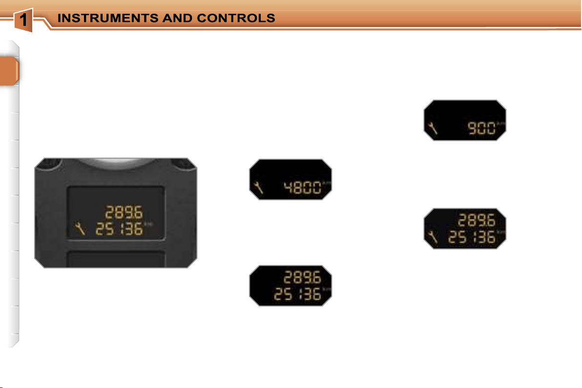
Service indicator
System which informs the driver when
the next service is due, in accord-
ance with the manufacturer’s servicing
schedule.
The point at which the service is due is
calculated from the last indicator zero
reset. It is determined by two para-
meters:
- the distance travelled,
- the time elapsed since the last service.
More than 500 miles (1 000 km)
remain before the next service is
due
For 5 seconds after the ignition is
switched on, the spanner symbolising
the service operations comes on. The
distance recorder display line indicates
the distance remaining before the next
service is due.
Example:
4 800 miles/km remain be-
fore the next service is due.
For 5 seconds after the ignition is
switched on, the display indicates:
5 seconds after the ignition is switched
on,
the spanner is switched off
; the
distance recorder resumes its normal
operation. The display then indicates
the total and trip distances.
Less than 500 miles (1 000 km)
remain before the next service is due
Example:
400 miles (900 km) remain
before the next service is due.
For 5 seconds after the ignition is
switched on, the display indicates:
5 seconds after the ignition is switched
on, the distance recorder resumes its
normal operation.
The spanner re-
mains on
to indicate that a service
must be carried out soon.
i
i
29
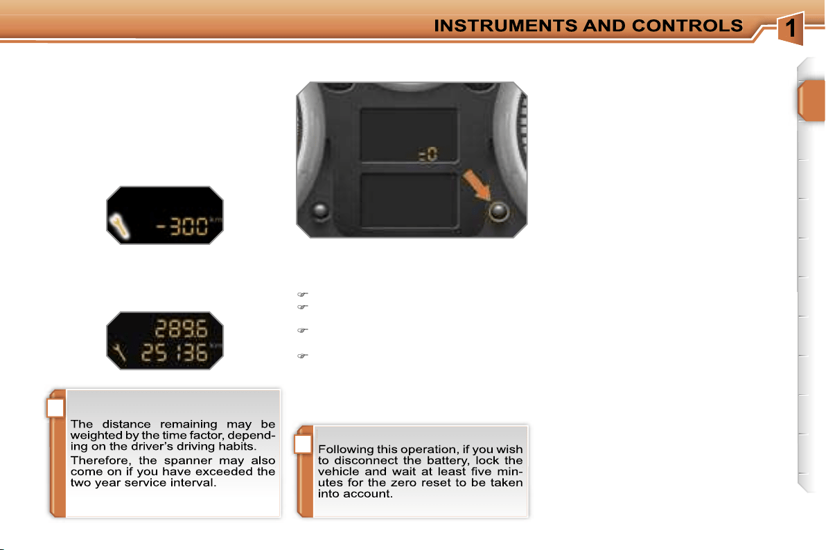
Service indicator zero reset
After each service, the service indicator
must be reset to zero.
To do this, carry out the following pro-
cedure:
switch off the ignition,
press and hold the trip distance re-
corder zero reset button,
switch on the ignition; the distance re-
corder display begins a countdown,
when the display indicates
"=0"
, re-
lease the button; the spanner disap-
pears.
Service overdue
For 5 seconds after the ignition is
switched on,
the spanner flashes
to
indicate that the service must be carried
out as soon as possible.
Example:
the service is overdue by
300 miles (km).
For 5 seconds after the ignition is
switched on, the display indicates:
5 seconds after the ignition is switched
on, the distance recorder resumes its
normal operation.
The spanner re-
mains lit.
i
30
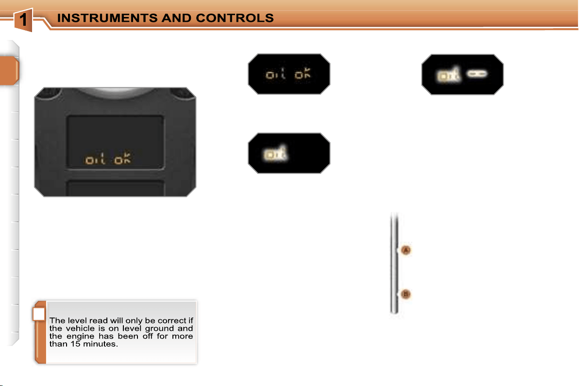
Engine oil level indicator
System which informs the driver of the
validity or invalidity of the engine oil
level.
This information is indicated for a few
seconds when the ignition is switched
on, after the service information.
Oil level correct
Lack of oil
Oil level gauge fault
Dipstick
This is indicated by the flashing of
"OIL"
, linked with the service warning
light, accompanied by an audible signal
and a message on the multifunction dis-
play.
If the lack of oil is confirmed by a check
using the dipstick, it is essential that the
level is topped up to prevent damage to
the engine.
This is indicated by the flashing of
"OIL --"
.
Contact a PEUGEOT dealer.
Refer to the "Checks" section to locate
the dipstick and the oil filler cap on your
engine.
There are 2 marks on the
dipstick:
-
A
= max; never exceed
this level,
-
B
= min; top up the level
via the oil filler cap, using
the type of oil suited to
your engine.
31
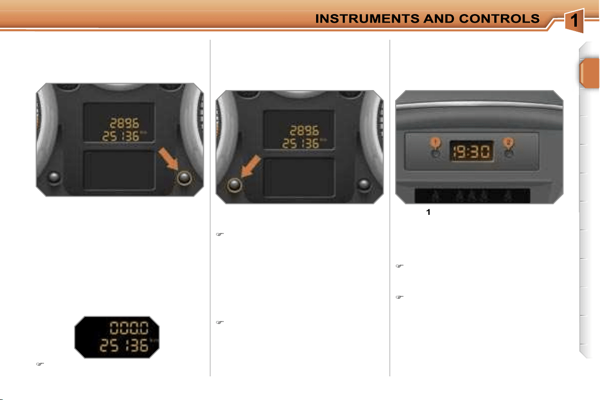
Total distance recorder
System which measures the total distance
travelled by the vehicle during its life.
Lighting rheostat
System for manual adjustment of the
brightness of the instruments and con-
trols in relation to the exterior bright-
ness.
CLOCK
Integrated system which displays the
time with independent setting of the
hours and minutes.
The total and trip distances are dis-
played for thirty seconds when the ig-
nition is switched off, when the driver’s
door is opened and when the vehicle is
locked or unlocked.
Trip distance recorder
System which measures a distance
travelled during a day or other period
until it is reset to zero by the driver.
With the ignition on, press the button
until zeros appear.
Activation
When the lights are on:
press the button to change the bright-
ness of the instruments and controls,
when the lighting reaches the mini-
mum setting, release the button,
then press again to increase it,
or
when the lighting reaches the maxi-
mum setting, release the button,
then press again to reduce it,
when the lighting reaches the level of
brightness required, release the button.
Button
1
: setting of the hours.
Button
2
: setting of the minutes.
Deactivation
When the lights are off, or in day mode on
vehicles fitted with daytime lights, pressing
the button does not have any effect.
Setting
Press the corresponding button brief-
ly to obtain slow scrolling.
or
Continue to press the corresponding
button to obtain rapid scrolling.
32
Displays on the screen
This displays the following information:
- the time,
- the date,
- the outside temperature* (this flashes
if there is a risk of ice),
- the status of the accesses (doors,
boot, ...),
- the trip computer (refer to the end of
the section).
Warning messages (e.g.: "Emission
control system faulty") or information
messages (e.g.: "Boot open") may ap-
pear temporarily. These can be cleared
by pressing the
"ESC"
button.
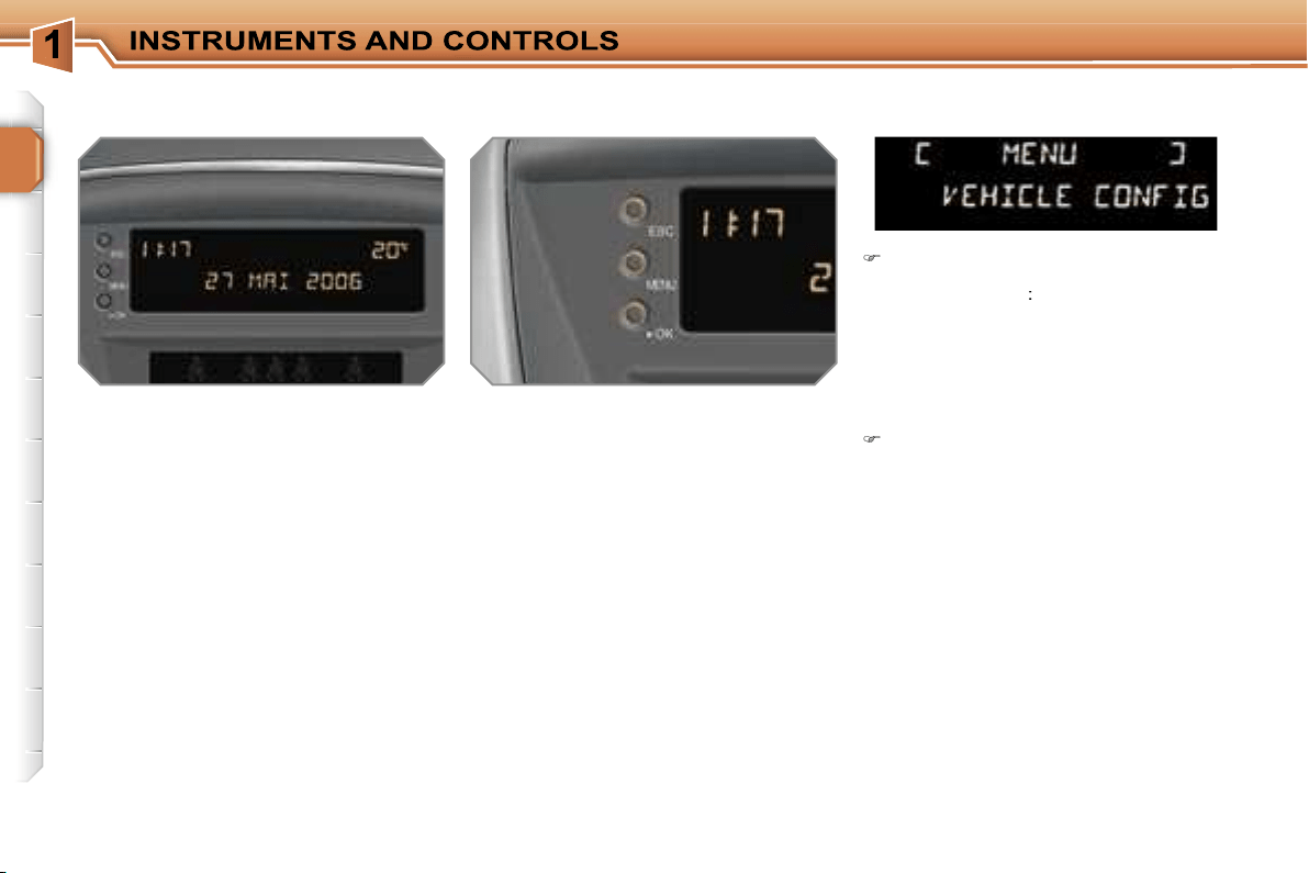
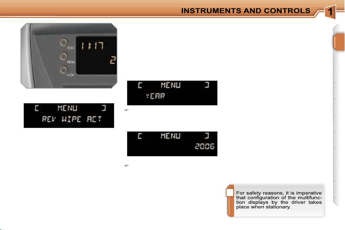
MONOCHROME SCREEN A
(without RD4 audio equipment)
Controls
General menu
There are three display control buttons:
-
"ESC"
to abandon the operation in
progress,
-
"MENU"
to scroll through the menus
or sub-menus,
-
"OK"
to select the menu or sub-menu
required.
Press the
"MENU"
button to scroll
through the various menus of the
general menu
:
- vehicle configuration,
- options,
- display settings,
- languages,
- units.
Press the
"OK"
button to select the
menu required.
* With air conditioning only.
!
33
Vehicle configuration
Options
Once the "Options" menu has been se-
lected, you can start diagnostics of the
status of the equipment (active, not ac-
tive, faulty).
Languages
Once the "Languages" menu has been
selected, you can change the language
used by the display (Français, Italiano,
Nederlands, Portugues, Portugues-
Brasil, Deutsch, English, Espanol).
Display settings
Once the "Display settings" menu has
been selected, you can gain access to
the following settings:
- year,
- month,
- day,
- hour,
- minutes,
- 12 or 24 hour mode.
Units
Once the "Units" menu has been
selected, you can change the units of
the following parameters:
- temperature (°C or °F),
- fuel consumption (l/100 km, mpg or
km/l).
Once you have selected a setting,
press the
"OK"
button to change its
value.
Wait for approximately ten sec-
onds without any action to allow
the changed data to be recorded or
press the
"ESC"
button to cancel.
The display then returns to the normal
display.
Once the "Vehicle configuration" menu
has been selected, you can activate or
deactivate the following equipment:
- wiper linked with reverse gear (refer to
the "Visibility" section),
- directional headlamps (refer to the
"Visibility" section),
- "follow-me-home" lighting (refer to the
"Visibility" section).
34
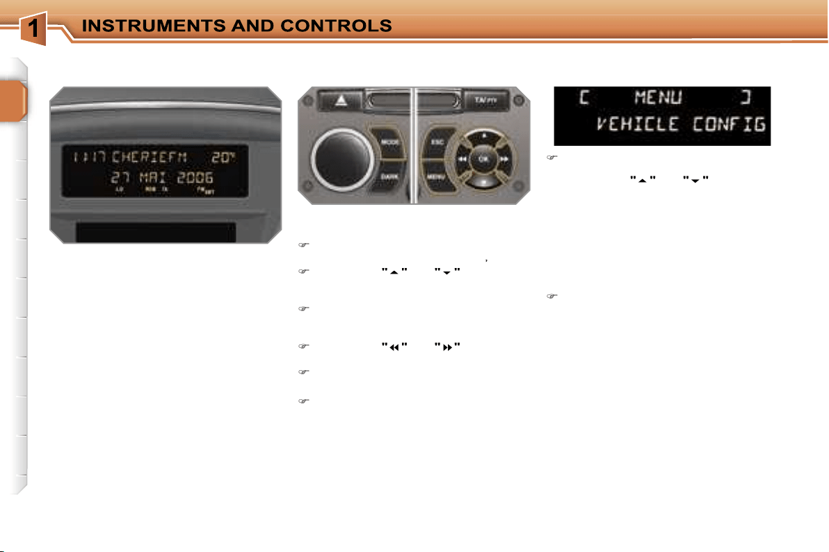
MONOCHROME SCREEN A
Controls
Displays on the screen
This displays the following information:
- the time,
- the date,
- the outside temperature* (this flashes
if there is a risk of ice),
- the status of the accesses (doors,
boot, ...),
- the audio sources (radio, CD, ...),
- the trip computer (refer to the end of
the section).
Warning messages (e.g.: "Emission
control system faulty") or information
messages (e.g.: "Boot open") may ap-
pear temporarily. These can be cleared
by pressing the
"ESC"
button.
General menu
Press the
"MENU"
button to gain
access to the
general menu
, then
press the
"
"
or
"
"
buttons to
scroll through the various menus:
- radio-CD,
- vehicle configuration,
- options,
- display settings,
- languages,
- units.
Press the
"OK"
button to select the
menu required.
From the RD4 audio equipment control
panel, you can:
press the
"MENU"
button to gain
access to the
general menu
,
press the
"
"
or
"
"
buttons to
scroll through the items on the
screen,
press the
"MODE"
button to change
the permanent application (trip com-
puter, audio source, ...),
press the
"
"
or
"
"
buttons to
change a setting value,
press the
"OK"
button to confirm,
or
press the
"ESC"
button to abandon
the operation in progress.
Radio-CD
With the RD4 audio equipment switched
on, once the "Radio-CD" menu has been
selected you can activate or deactivate
the functions linked with use of the radio
(RDS, REG), the CD or the CD changer
(introscan, shuffle, CD repeat).
For further details concerning the
"Radio-CD" application, refer to the
RD4 part of the "Audio and Telematics"
section.
* With air conditioning only.
!
35
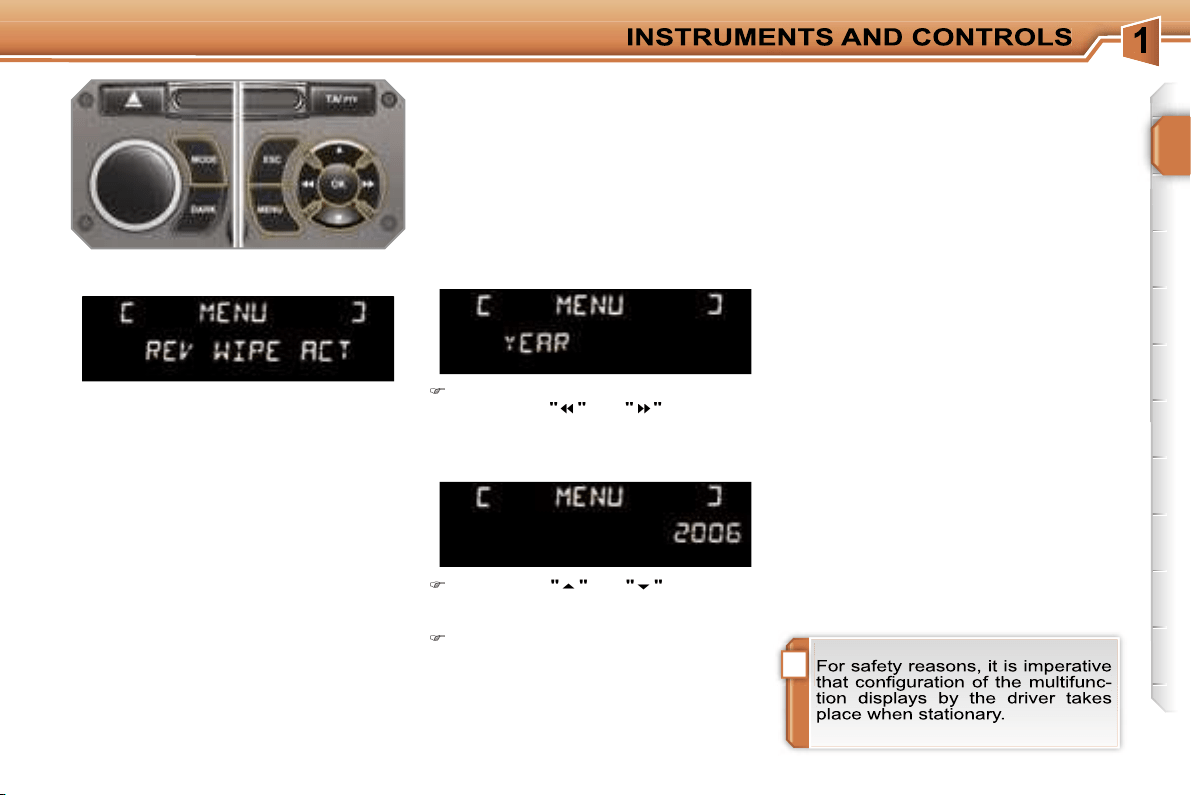
Display settings
Once the "Display settings" menu has
been selected, you can gain access to
the following settings:
- year,
- month,
- day,
- hour,
- minutes,
- 12 or 24 hour mode.
Languages
Once the "Languages" menu has been
selected, you can change the language
used by the display (Français, Italiano,
Nederlands, Portugues, Portugues-
Brasil, Deutsch, English, Espanol).
Units
Once the "Units" menu has been se-
lected, you can change the units of the
following parameters:
- temperature (°C or °F),
- fuel consumption (l/100 km, mpg or
km/l).
Once you have selected a setting,
press the
"
"
or
"
"
buttons to
change its value.
Press the
"
"
or
"
"
buttons to
switch respectively to the previous
or next setting.
Press the
"OK"
button to record the
change and return to the normal dis-
play or press the
"ESC"
button to
cancel.
Vehicle configuration
Options
Once the "Options" menu has been se-
lected, you can start diagnostics of the
status of the equipment (active, not ac-
tive, faulty).
Once the "Vehicle Configuration" menu
has been selected, you can activate or
deactivate the following equipment:
- wiper linked with reverse gear (refer to
the "Visibility" section),
- directional headlamps (refer to the
"Visibility" section),
- "follow-me-home" lighting (refer to the
"Visibility" section).
36
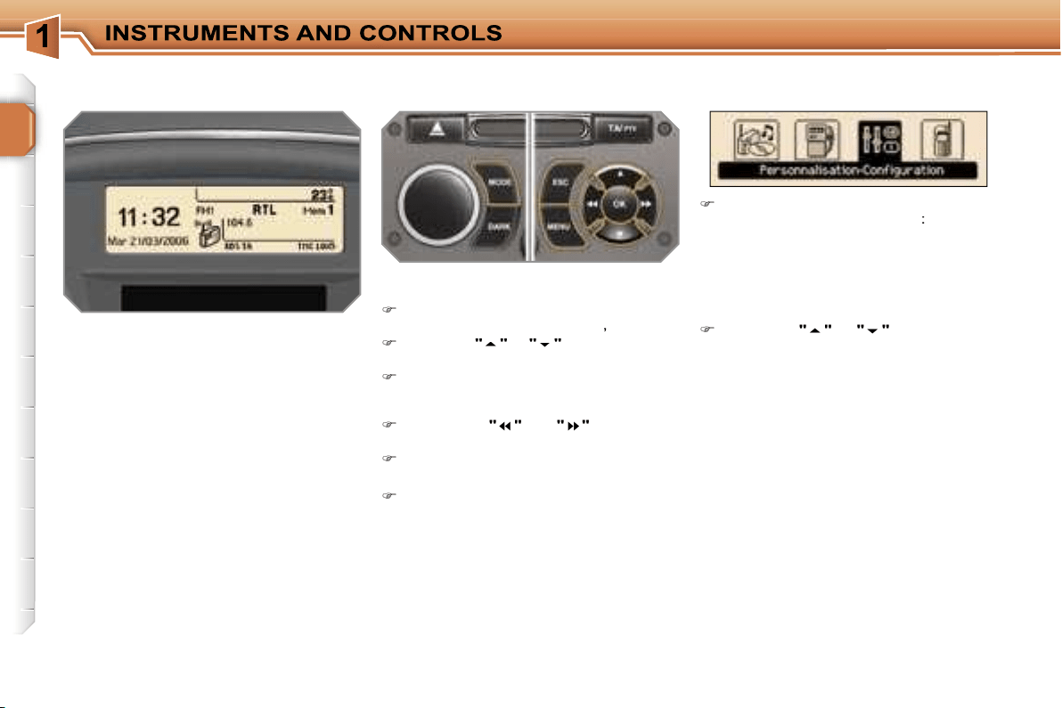
MONOCHROME SCREEN C
General menu
Displays on the screen
This displays the following information:
- the time,
- the date,
- the outside temperature* (this flashes
if there is a risk of ice),
- the status of the accesses (doors,
boot, ...),
- the audio sources (radio, CD, ...),
- the trip computer (refer to the end of
the section).
Warning messages (e.g.: "Emission
control system faulty") or information
messages (e.g.: "Automatic switching
on of the headlamps activated") may ap-
pear temporarily. These can be cleared
by pressing the
"ESC"
button.
"Audio functions" menu
With the RD4 audio equipment switched
on, once this menu has been selected
you can activate or deactivate the func-
tions linked with use of the radio (RDS,
REG, RadioText), the CD or the CD
changer (introscan, shuffle, CD repeat).
For further details concerning the "Au-
dio functions" application, refer to the
RD4 part of the "Audio and Telematics"
section.
Controls
From the RD4 audio equipment control
panel, you can:
press the
"MENU"
button to gain ac-
cess to the
general menu
,
press the
"
"
or
"
"
buttons to scroll
through the items on the screen,
press the
"MODE"
button to change
the permanent application (trip com-
puter, audio source, ...),
press the
"
"
or
"
"
buttons to
change a setting value,
press the
"OK"
button to confirm,
or
press the
"ESC"
button to abandon
the operation in progress.
Press the
"MENU"
button to gain ac-
cess to the
general menu
:
- audio functions,
- trip computer (refer to the end of
the section),
- personalisation-configuration,
- telephone (hands-free kit).
Press the
"
"
or
"
"
buttons to se-
lect the menu required, then confirm
by pressing the
"OK"
button.
* With air conditioning only.
"Trip computer" menu
Once this menu has been selected, you
can consult information concerning the
status of the vehicle (warnings log, sta-
tus of the functions, ...).
!
37
Define the vehicle parameters
Once this menu has been selected, you
can activate or deactivate the following
equipment:
- wiper linked with reverse gear (refer to
the "Visibility" section),
- directional headlamps (refer to the
"Visibility" section),
- "follow-me-home" lighting (refer to the
"Visibility" section).
"Telephone" menu
With the RD4 audio equipment switched
on, once this menu has been select-
ed you can configure your Bluetooth
hands-free kit (matching), consult the
various telephone directories (calls log,
services, ...) and manage your commu-
nications (pick up, hang up, call waiting,
secret mode, ...).
For further details concerning the "Tele-
phone" application, refer to the RD4 part
of the "Audio and Telematics" section.
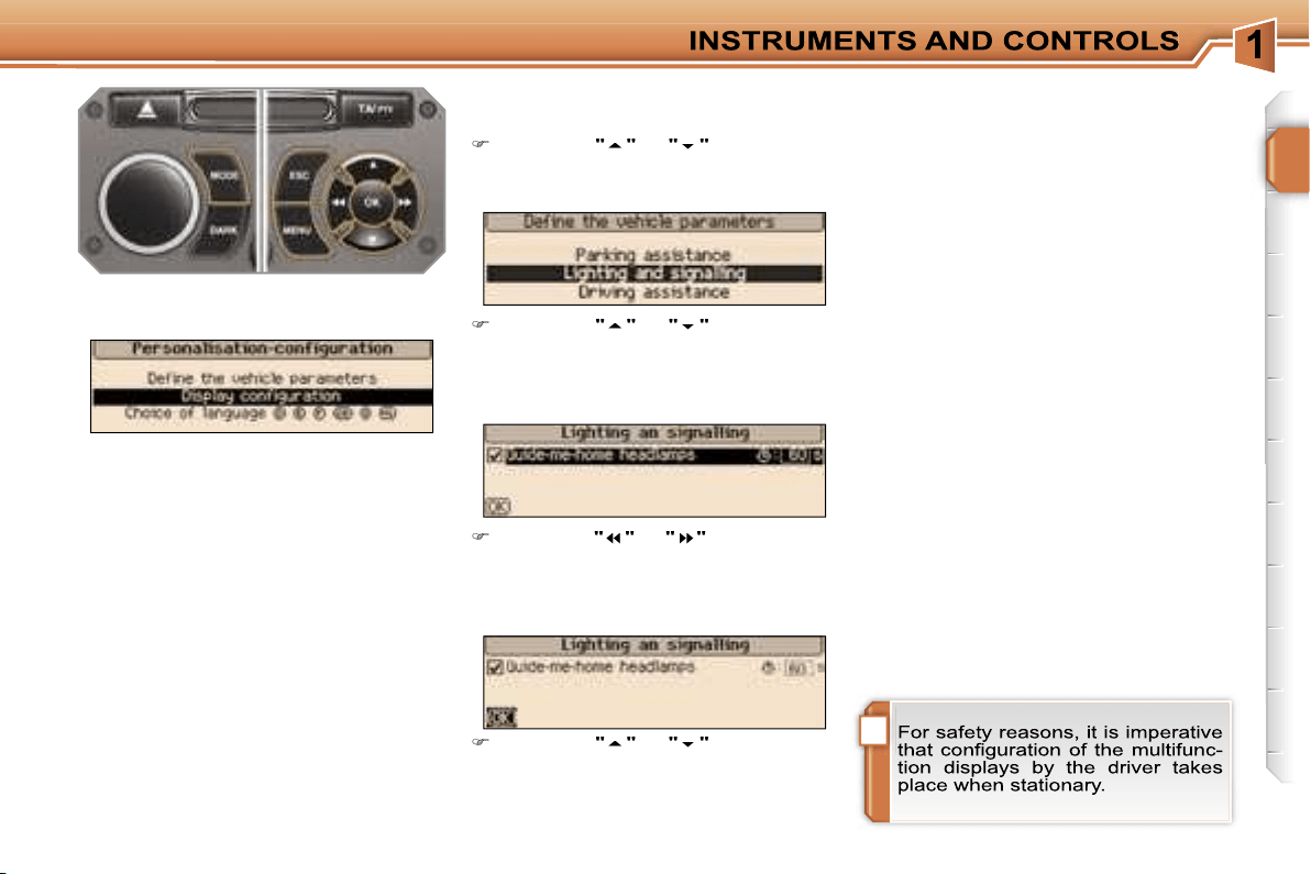
Display configuration
Once this menu has been selected, you
can gain access to the following set-
tings:
- brightness-video setting,
- date and time setting,
- selection of the units.
Selection of the language
Once this menu has been selected,
you can change the language used by
the display (Deutsch, English, Espanol,
Français, Italiano, Nederlands, Portu-
gues, Portugues-Brasil).
Example: setting of the duration of the
"follow-me-home" lighting
"Personalisation-Configuration"
menu
Once this menu has been selected, you
can gain access to the following func-
tions:
- define the vehicle parameters,
- display configuration,
- selection of the language.
Press the
"
"
or
"
"
buttons, then
the
"OK"
button to select the menu
required.
Press the
"
"
or
"
"
buttons, then
the
"OK"
button to select the "Fol-
low-me-home lighting" line.
Press the
"
"
or
"
"
buttons to set
the value required (15, 30 or 60 sec-
onds), then press the
"OK"
button to
confirm.
Press the
"
"
or
"
"
buttons, then
the
"OK"
button to select the
"OK"
box and confirm or press the
"ESC"
button to cancel.
38
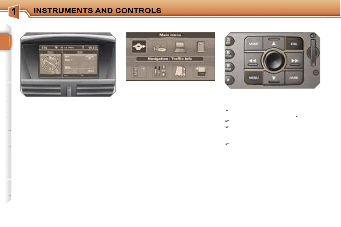
COLOUR SCREEN DT
Displays on the screen
When the RT3 GPS audio/telephone is
switched on, select the menu which cor-
responds to the following applications:
- the satellite navigation system and the
traffic information,
- the audio sources (radio, CD, ...),
- the trip computer (consumption,
route, ...),
- the directories,
- the telephone,
- the configuration of the screen and
the setting of the parameters of the
vehicle’s equipment,
- the guidance on the map,
- the displaying of a video.
Controls
When the ignition is switched on, this
displays the following information auto-
matically and directly:
- the time,
- the date,
- the outside temperature (if there is a
risk of ice, you are warned by a mes-
sage).
Warning messages (e.g.: "Fuel level
low") and vehicle function status mes-
sages (e.g.: "Automatic switching on of
the headlamps activated") may appear
temporarily. These can be cleared by
pressing the
"ESC"
button.
From the RT3 GPS audio/telephone
control panel, to select one of the ap-
plications:
press the
"MENU"
button to gain ac-
cess to the
general menu
,
turn the dial to move the selection,
press the dial to confirm the selec-
tion,
or
press the
"ESC"
button to abandon
the operation in progress and return
to the previous display.
For further details concerning these ap-
plications, refer to the RT3 part of the
"Audio and Telematics" section.
General menu
39
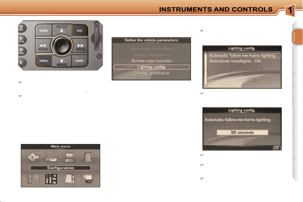
Define the vehicle parameters
Once the "Define the vehicle parame-
ters" menu has been selected, you can
activate or deactivate certain driving
and comfort equipment:
- wiper linked with reverse gear (refer to
the "Visibility" section),
- directional headlamps (refer to the
"Visibility" section),
- "follow-me-home" lighting and dura-
tion (refer to the "Visibility" section).
Example: setting the duration of the
"follow-me-home" lighting
Turn the dial to select the
"Lighting
configuration"
menu, then press it
to confirm.
Select the line "Duration of the "follow-
me-home" lighting" then confirm.
"Configuration" menu
Press the
"MENU"
button on the
RT3 GPS audio/telephone to gain
access to the
general menu
.
Turn the dial to select the
"Configu-
ration"
menu, then press it to con-
firm.
Once this menu has been selected, you
can gain access to the following func-
tions:
Select the duration then press the
dial.
Turn the dial to set the value required
(15, 30 or 60 seconds), then press
the dial.
Select the
"OK"
box, then confirm.
!
i
40
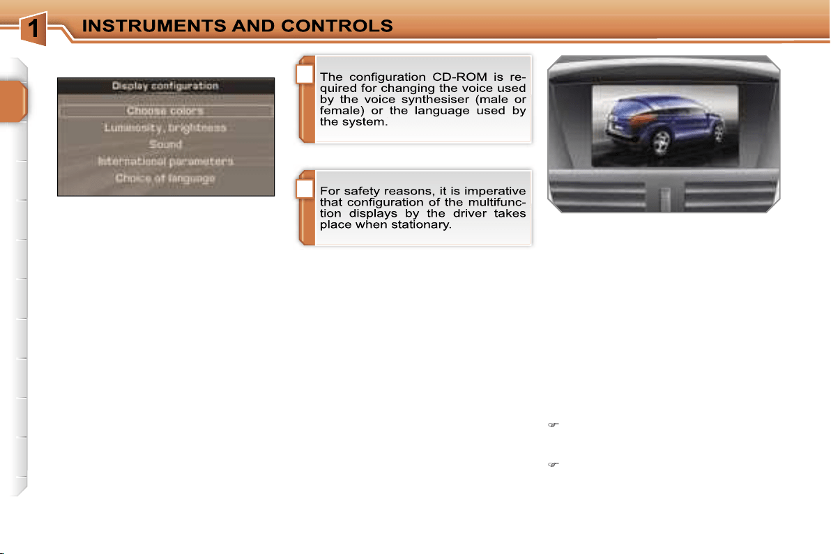
Once the "Display configuration" menu
has been selected, you gain access to
the following parameters:
- selection of the palette of colours
available for the display,
- setting of the brightness and brilliance
of the display,
- setting of the voice commands; set-
ting of the voice synthesiser (volume,
male or female); activation of the aux-
iliary input AUX,
- from the "international parameters",
setting of the date and time (12 or
24 hour mode, adjustment of the
minutes on GPS); selection of the
units (temperature in °Celsius or
°Fahrenheit; consumption in l/100 km
or mpg or km/l),
- selection of the display, information and
voice commands language (Français,
English, Italiano, Portugues, Espanol,
Deutsch, Nederlands).
Display configuration
"Video" menu
You can connect video equipment
(camcorder, digital camera, DVD play-
er, ...) to the three audio/video sockets,
located in the glove box.
Videos can only be displayed when
stationary.
Once this menu has been selected, you
can select:
- "Activate video mode" to activate/
deactivate the video,
- "Video parameters" to set the display
format, the brightness, the contrast
and the colours.
Press the
"MODE"
or
"DARK"
but-
ton to disconnect the displaying of
the video.
Press the
"SOURCE"
button sev-
eral times in succession to select an
audio source other than that of the
video.
41
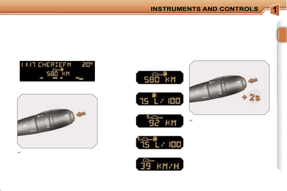
TRIP COMPUTER
Press the button, located at the end
of the
wipers stalk
, to display the
various items of trip computer data
in succession.
The trip computer data is the following:
System which provides current infor-
mation concerning the route travelled
(range, consumption, ...).
Press the control for more than two
seconds to reset the distance travel-
led, the average consumption and
the average speed to zero.
Monochrome screen A
Zero reset
Data displays
- the range,
- the current consumption,
- the distance travelled,
- the average consumption,
- the average speed.

!
i
i
43
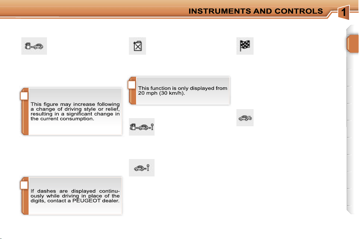
Distance remaining to be
travelled
(km or miles)
This is the distance remaining
to be travelled to the final destination. It
is calculated either instantly by the navi-
gation system if guidance is activated,
or entered by the user.
If the distance is not entered, dashes
are displayed in place of the digits.
Average speed
(km/h or mph)
This is the average speed cal-
culated since the last trip com-
puter zero reset (ignition on).
Range
(km or miles)
This indicates the number of
miles (or kilometres) which
can still be travelled with the fuel re-
maining in the tank in relation to the
average consumption over the last few
miles (kilometres) travelled.
Current consumption
(l/100 km or km/l or mpg)
This is the average quantity of
fuel consumed over the last few
seconds.
Average consumption
(l/100 km or km/l or mpg)
This is the average quantity
of fuel consumed since the
last trip computer zero re-
set.
Distance travelled
(km or miles)
This indicates the distance
travelled since the last trip
computer zero reset.
A few definitions…
When the range falls below 20 miles
(30 km), dashes are displayed. After fill-
ing with at least 5 litres of fuel, the range
is recalculated and is displayed when it
exceeds 60 miles (100 km).
42
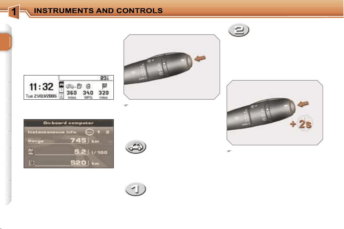
Colour screen DT
- the current information tab
with:
• the range,
• the current consumption,
• the distance remaining to
be travelled,
Route zero reset
Monochrome screen C
Press the button, located at the end
of the
wipers stalk
, to display the
various trip computer tabs in succes-
sion:
Data displays
When the route required is displayed,
press the control for more than two
seconds.
- the route
"1"
tab with:
• the distance travelled,
• the average consumption,
• the average speed,
for the first route.
- the route
"2"
tab with:
• the distance travelled,
• the average consumption,
• the average speed, for
the second route.
Routes
"1"
and
"2"
are independent
but their use is identical.
Route
"1"
permits, for example, daily
calculations, and route
"2"
monthly cal-
culations.
TRIP COMPUTER
System which provides current infor-
mation concerning the route travelled
(range, consumption, …).
!
i
i
43
Distance remaining to be
travelled
(km or miles)
This is the distance remaining
to be travelled to the final destination. It
is calculated either instantly by the navi-
gation system if guidance is activated,
or entered by the user.
If the distance is not entered, dashes
are displayed in place of the digits.
Average speed
(km/h or mph)
This is the average speed cal-
culated since the last trip com-
puter zero reset (ignition on).
Range
(km or miles)
This indicates the number of
miles (or kilometres) which
can still be travelled with the fuel re-
maining in the tank in relation to the
average consumption over the last few
miles (kilometres) travelled.
Current consumption
(l/100 km or km/l or mpg)
This is the average quantity of
fuel consumed over the last few
seconds.
Average consumption
(l/100 km or km/l or mpg)
This is the average quantity
of fuel consumed since the
last trip computer zero re-
set.
Distance travelled
(km or miles)
This indicates the distance
travelled since the last trip
computer zero reset.
A few definitions…
When the range falls below 20 miles
(30 km), dashes are displayed. After fill-
ing with at least 5 litres of fuel, the range
is recalculated and is displayed when it
exceeds 60 miles (100 km).
44
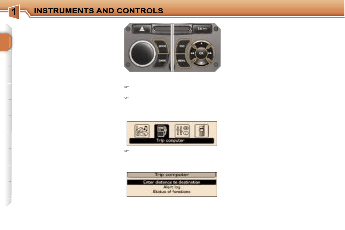
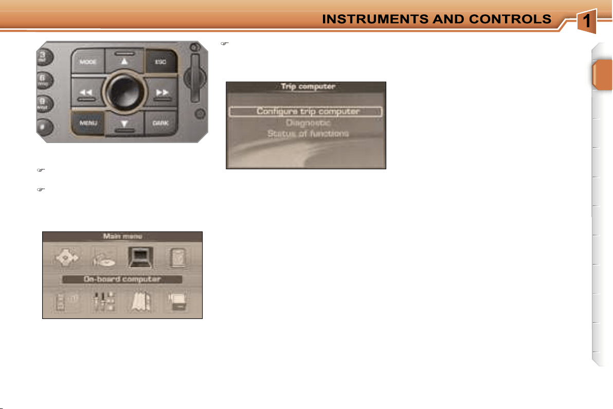
"TRIP COMPUTER" MENU
Screen C
Press the
"MENU"
button to gain ac-
cess to the general menu.
Press the arrows, then the
"OK"
but-
ton to select the
"Trip computer"
menu.
On the
"Trip computer"
menu,
select one of the following applica-
tions:
Warnings log
This summarises the active warning
messages, displaying them in succes-
sion on the multifunction display.
Status of the functions
This summarises the active or inactive
status of the functions present on the
vehicle.
Enter the distance to the destination
This enables you to enter an approxi-
mate value for the distance to the final
destination.
System which provides general infor-
mation concerning the status of certain
equipment with which your vehicle is
equipped, such as the warnings log, the
status of the functions...
45
Trip computer configuration
This function enables you to enter the
distance to the destination (when no
guidance is activated; otherwise, the
information is provided by the naviga-
tion) and change the units (°C or °F, km
and litres, miles and Gallons or km and
km/litre).
Diagnostics
This presents the information relating to
the warnings log, the level of charge re-
maining in the back-up battery and the
number of satellites which can be seen
by the GPS system.
Screen DT
Press the
"MENU"
button to gain
access to the general menu.
Turn the dial and press it to select
the
"Trip computer"
menu.
On the
"Trip computer"
menu,
select one of the following applica-
tions:
Status of the functions
This summarises the active or inactive
status of the functions present on the
vehicle.
46
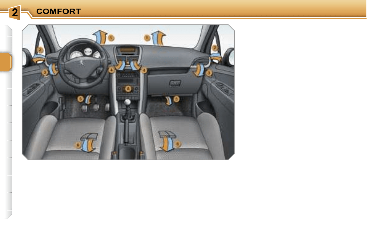
VENTILATION
System which creates and maintains
comfortable conditions in the vehicle’s
passenger compartment.
Air treatment
The incoming air follows various routes
depending on the controls selected by
the driver:
- direct arrival in the passenger com-
partment (air intake),
- passage through a heating circuit
(heating),
- passage through a cooling circuit (air
conditioning).
The temperature control enables you to
obtain the level of comfort required by
mixing the air of the various circuits.
The air distribution control enables you
to diffuse the air in the passenger com-
partment combining several air vents.
The air flow control enables you to in-
crease or reduce the speed of the ven-
tilation blower.
Air intake
The air circulating in the passenger com-
partment is filtered and originates either
from the outside via the grille located at
the base of the windscreen or from the in-
side in air recirculation mode.
Control panel
The controls of this system are grouped
together on control panel
A
on the cen-
tre console. Depending on the model,
the functions offered are:
- the level of comfort required,
- the air flow,
- the air distribution,
- the de-icing and demisting,
- the manual or automatic air condition-
ing controls.
Air diffusion
1.
Windscreen de-icing or demisting
vents.
2.
Front side window de-icing or
demisting vents.
3.
Side adjustable and closing vents.
4.
Central adjustable and closing
vents.
5.
Air outlets to the front footwells.
6.
Air outlets to the rear footwells.
i
47
RECOMMENDATIONS FOR VENTILATION AND
AIR CONDITIONING

48
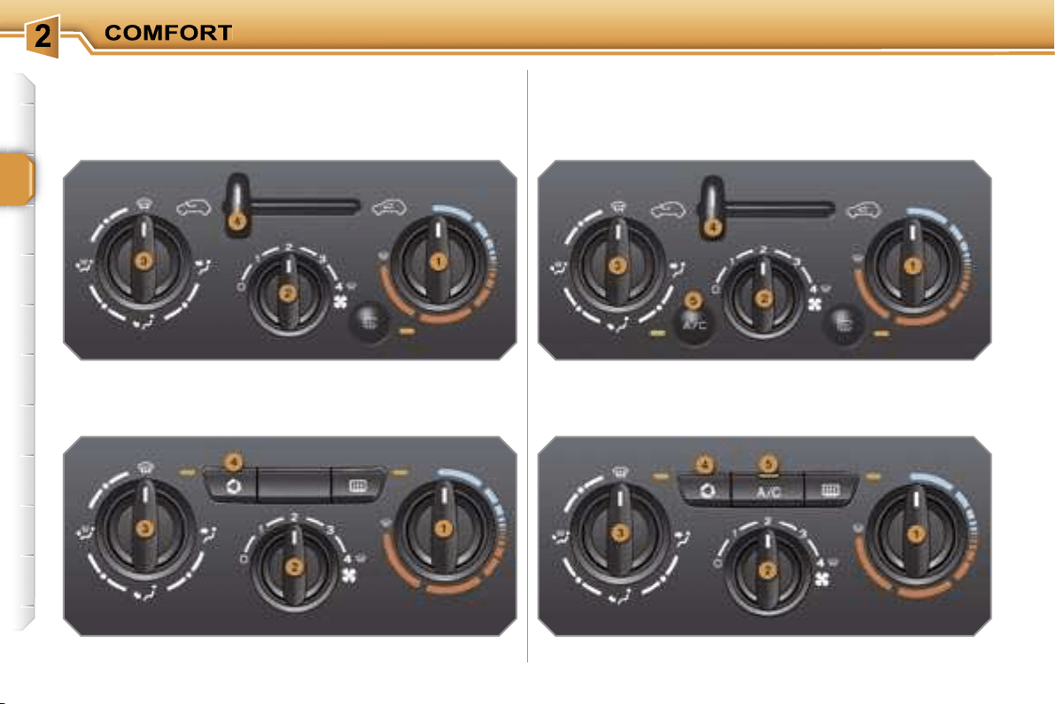
HEATING/VENTILATION
Control panel with manual control
Control panel with electric control
MANUAL AIR CONDITIONING
Control panel with manual control
Control panel with electric control
i
49
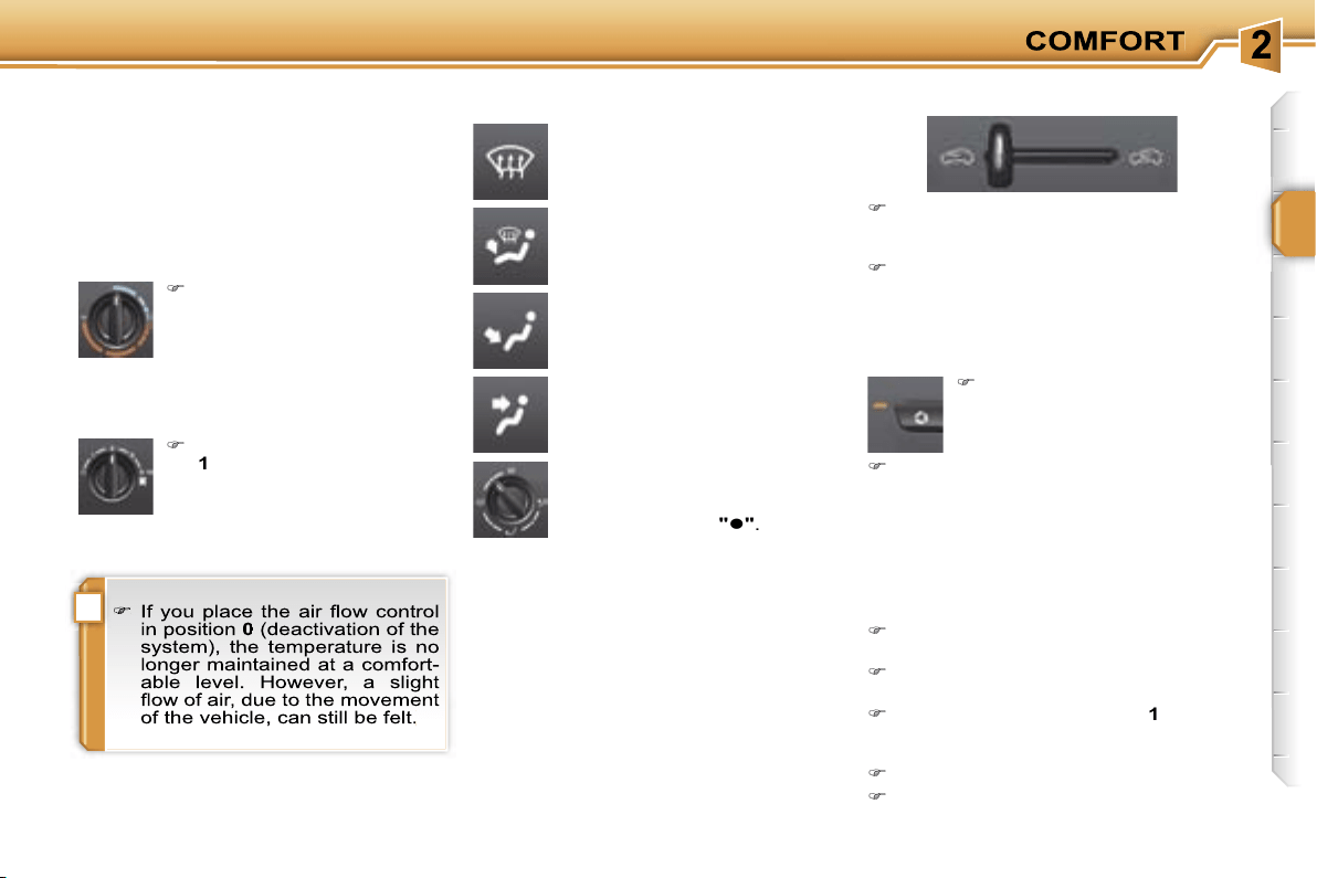
2. Air flow adjustment
Turn the dial from position
1
to position
4
to obtain an
air flow sufficient to ensure
your comfort.
Windscreen, side windows
and footwells.
Footwells.
(vents closed)
Central and side vents.
Turn the dial from blue
(cold) to red (hot) to ad-
just the temperature to suit
your requirements.
Windscreen and side win-
dows.
1. Temperature adustment
The air distribution can be
adapted by placing the dial
in an intermediate position,
marked by a dot
"
"
.
The heating/ventilation or air condition-
ing systems can only operate when the
engine is running.
HEATING/VENTILATION AND
MANUAL AIR CONDITIONING
Control panel with manual control
4. Air intake/Air recirculation
The intake of exterior air prevents the
formation of condensation on the wind-
screen and side windows.
The recirculation of interior air prevents
exterior odours and smoke from enter-
ing the passenger compartment.
Return to exterior air intake mode as
soon as possible to avoid deterioration
of the air quality and prevent condensa-
tion.
Control panel with electric control
De-icing-Demisting
To quickly de-ice or demist the wind-
screen and side windows:
place the air intake control
4
in the
"Exterior air intake" position,
place the air distribution dial
3
in the
"Windscreen" position,
place the temperature dial
1
and the
air flow dial
2
in the maximum posi-
tion,
close the central vents,
switch on the air conditioning by
pressing the
"A/C"
button.
3. Air distribution adjustment
Move the manual control to the right
to the "Interior air recirculation" posi-
tion.
Move the manual control to the left
to return to the "Exterior air intake"
position.
Press the button to recir-
culate the interior air. This
is displayed by lighting of
the indicator light.
Press the button again to permit the
intake of exterior air. This is displayed
by switching off of the indicator light.
48
HEATING/VENTILATION
Control panel with manual control
Control panel with electric control
MANUAL AIR CONDITIONING
Control panel with manual control
Control panel with electric control

i
49
2. Air flow adjustment
Turn the dial from position
1
to position
4
to obtain an
air flow sufficient to ensure
your comfort.
Windscreen, side windows
and footwells.
Footwells.
(vents closed)
Central and side vents.
Turn the dial from blue
(cold) to red (hot) to ad-
just the temperature to suit
your requirements.
Windscreen and side win-
dows.
1. Temperature adustment
The air distribution can be
adapted by placing the dial
in an intermediate position,
marked by a dot
"
"
.
The heating/ventilation or air condition-
ing systems can only operate when the
engine is running.
HEATING/VENTILATION AND
MANUAL AIR CONDITIONING
Control panel with manual control
4. Air intake/Air recirculation
The intake of exterior air prevents the
formation of condensation on the wind-
screen and side windows.
The recirculation of interior air prevents
exterior odours and smoke from enter-
ing the passenger compartment.
Return to exterior air intake mode as
soon as possible to avoid deterioration
of the air quality and prevent condensa-
tion.
Control panel with electric control
De-icing-Demisting
To quickly de-ice or demist the wind-
screen and side windows:
place the air intake control
4
in the
"Exterior air intake" position,
place the air distribution dial
3
in the
"Windscreen" position,
place the temperature dial
1
and the
air flow dial
2
in the maximum posi-
tion,
close the central vents,
switch on the air conditioning by
pressing the
"A/C"
button.
3. Air distribution adjustment
Move the manual control to the right
to the "Interior air recirculation" posi-
tion.
Move the manual control to the left
to return to the "Exterior air intake"
position.
Press the button to recir-
culate the interior air. This
is displayed by lighting of
the indicator light.
Press the button again to permit the
intake of exterior air. This is displayed
by switching off of the indicator light.
i
50
5. Air conditioning On/Off
The air conditioning is de-
signed to operate effectively in
all seasons, with the windows
closed.
The control button is located on
the heating or air conditioning
system control panel.
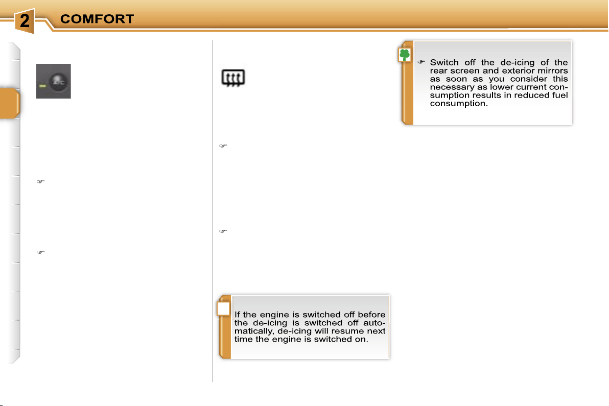
REAR SCREEN DE-ICING
Switching on
The rear screen de-icing can only oper-
ate when the engine is running.
Press this button to de-ice the rear
screen and the exterior mirrors. The
indicator light associated with the
button comes on.
Switching off
The de-icing switches off automatically
to prevent an excessive consumption of
current.
It is possible to stop the de-icing op-
eration before it is switched off au-
tomatically by pressing the button
again. The indicator light associated
with the button switches off.
It enables you to:
- lower the temperature, in summer,
- increase the effectiveness of the de-
misting, in winter above 0 °C.
Switching on
Press the
"A/C"
button, the associ-
ated indicator light comes on.
The air conditioning does not oper-
ate when the air flow adjustment dial
2 is in position "0".
Switching off
Press the
"A/C"
button again, the
associated indicator light switches
off.

i
50
5. Air conditioning On/Off
The air conditioning is de-
signed to operate effectively in
all seasons, with the windows
closed.
The control button is located on
the heating or air conditioning
system control panel.
REAR SCREEN DE-ICING
Switching on
The rear screen de-icing can only oper-
ate when the engine is running.
Press this button to de-ice the rear
screen and the exterior mirrors. The
indicator light associated with the
button comes on.
Switching off
The de-icing switches off automatically
to prevent an excessive consumption of
current.
It is possible to stop the de-icing op-
eration before it is switched off au-
tomatically by pressing the button
again. The indicator light associated
with the button switches off.
It enables you to:
- lower the temperature, in summer,
- increase the effectiveness of the de-
misting, in winter above 0 °C.
Switching on
Press the
"A/C"
button, the associ-
ated indicator light comes on.
The air conditioning does not oper-
ate when the air flow adjustment dial
2 is in position "0".
Switching off
Press the
"A/C"
button again, the
associated indicator light switches
off.
i
i
51
The air conditioning can only operate
with the engine running.
The driver and his front pas-
senger can each set the tem-
perature to suit their require-
ments.
Turn dial
2
or
3
to the left to reduce
the value or to the right to increase
it.
A setting around 21 enables you to ob-
tain an optimum level of comfort. De-
pending on your requirements, a setting
between 18 and 24 is usual.
In addition, it is recommended that you
avoid a left/right setting difference of
more than 3.
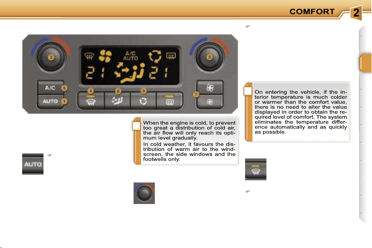
4. Automatic visibility programme
The automatic comfort pro-
gramme may not be sufficient
to quickly demist or de-ice the
windscreen and side windows
(humidity, several passen-
gers, ice...).
In this case, select the automatic vis-
ibility programme.
The system automatically controls the
air conditioning, the air flow and the air
intake and provides optimum distribu-
tion of the ventilation to the windscreen
and side windows.
Automatic operation
1. Automatic comfort programme
Press the
"AUTO"
button.
The
"AUTO"
symbol is
displayed.
2. Driver’s side adjustment
3. Passenger side adjustment
DUAL ZONE AUTOMATIC AIR CONDITIONING
We recommend that you use this mode:
it provides optimised automatic control
of all of the functions, passenger com-
partment temperature, air flow, air dis-
tribution and air recirculation, in accord-
ance with the comfort value that you
have selected.
This system is designed to operate ef-
fectively in all seasons, with the win-
dows closed.
The value indicated on the display cor-
responds to a level of comfort and not
to a temperature in degrees Celsius or
Fahrenheit.
!
!
i
52
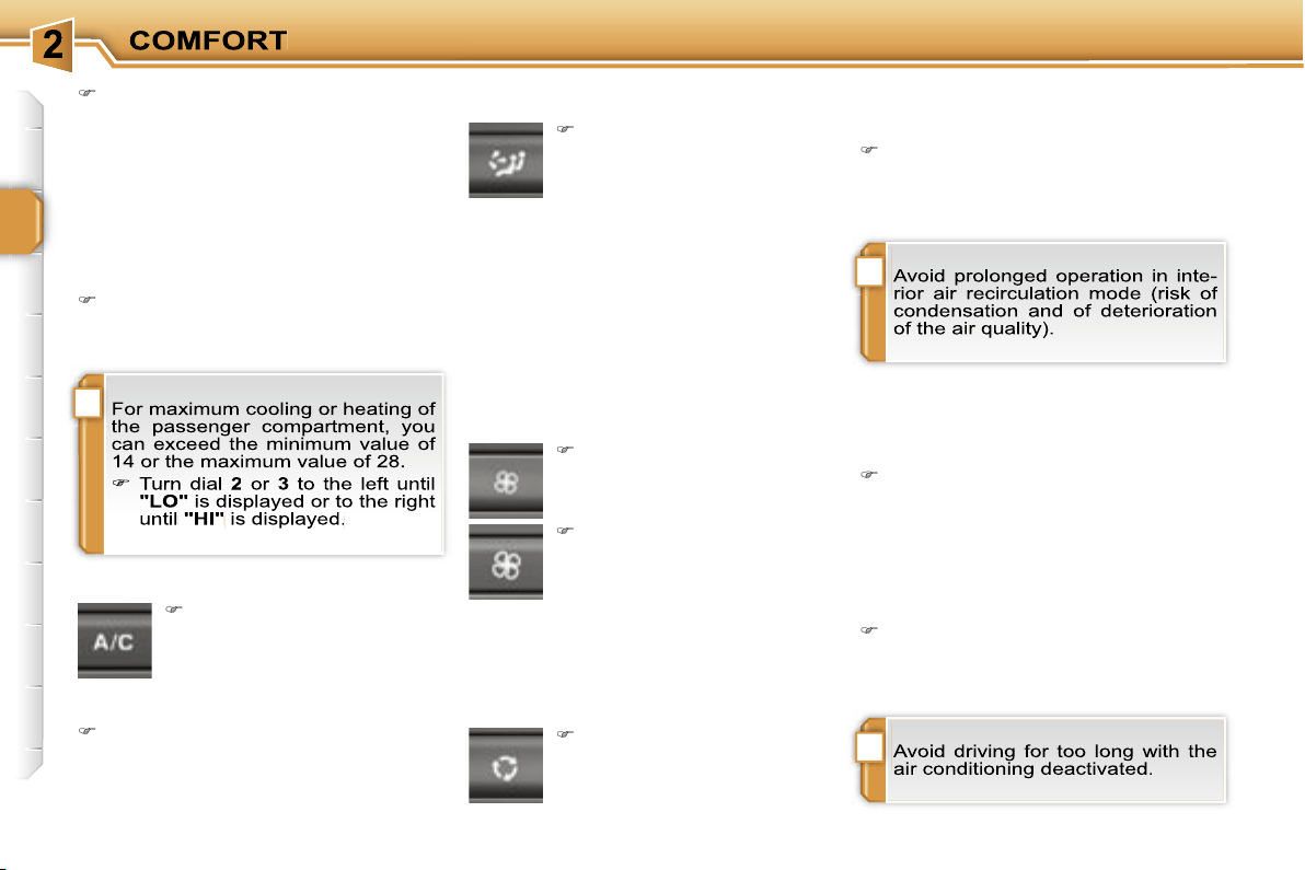
To exit this programme, press the
"vi-
sibility"
button again or the
"AUTO"
button, the indicator light on the button
switches off and
"AUTO"
is displayed.
Press this button to switch
the air conditioning off.
Switching the system off may result in
discomfort (humidity, condensation).
Press the button again to return to
automatic operation of the air con-
ditioning. The symbol
"A/C"
is dis-
played.
6. Air distribution adjustment
Press this button several
times in succession to di-
rect the air flow in turn to-
wards:
7. Air flow adjustment
Press the
"small fan"
but-
ton to reduce the air flow.
8. Air intake/Air recirculation
Deactivation of the system
Press the
"small fan"
button until
the fan symbol disappears.
This action deactivates all of the func-
tions of the air conditioning system.
The temperature is no longer main-
tained at a comfortable level. However,
a slight flow of air, due to the movement
of the vehicle, can still be felt.
Press the
"large fan"
button again
or the
"AUTO"
button to reactivate
the system with the values which
were set before it was deactivated.
Press this button to recir-
culate the interior air. The
air recirculation symbol is
displayed.
5. Air conditioning On/Off
- the windscreen, the side windows and
the footwells,
- the windscreen and side windows (de-
misting or de-icing),
- the central and side vents,
- the central vents, the side vents and
the footwells,
- the footwells.
Press the
"large fan"
button to increase the air
flow.
The air flow symbol, the fan, is filled in
progressively in relation to the value re-
quired.
Air recirculation prevents exterior odours
and smoke from entering the passenger
compartment.
As soon as possible, press this but-
ton again to permit the intake of ex-
terior air and prevent condensation.
Resuming manual control
Depending on your requirements, you
can make a different selection from that
offered by the system by changing a
setting. The other functions will still be
controlled automatically.
Press the
"AUTO"
button to return
to fully automatic operation.
!
i
i
53
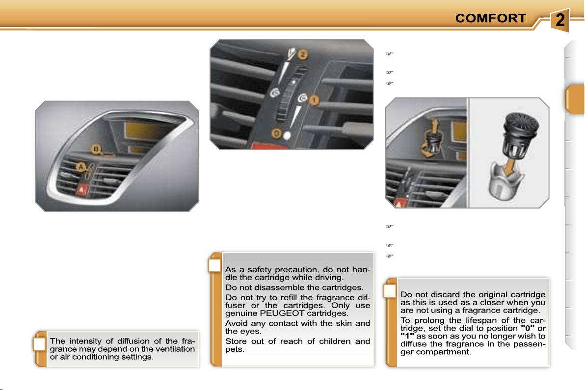
FRAGRANCE DIFFUSER
System which permits the diffusion of
fragrance in the passenger compartment
in accordance with your requirements,
by means of the adjustment dial and the
various fragrance cartridges available.
Fitting the cartridge
Remove the sealing cap from the
cartridge.
Install the cartridge in the fascia.
Press the cartridge and turn it one
quarter of a turn.
Controls
A. Adjustment dial.
This dial permits simultaneous adjust-
ment of the ventilation and of the intensity
of diffusion of the fragrance. There are
three main positions:
0.
Zero ventilation.
1.
Maximum ventilation/Zero diffusion.
2.
Maximum ventilation/Maximum
diffusion.
B. Fragrance cartridge.
This cartridge can be removed very
easily.
You can change it at any time and store
it, using the cap which seals it if it has
been partly used.
You can obtain different fragrance car-
tridges from your PEUGEOT dealer.
Removing the cartridge
Turn the cartridge one quarter of a
turn.
Remove the cartridge from the fascia.
Refit its sealing cap.
54
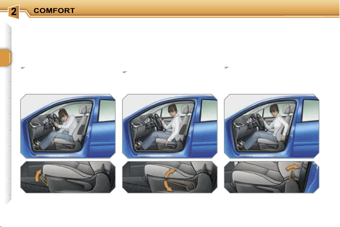
FRONT SEATS
Seat consisting of a seat cushion, seat
back and head restraint which can all
be adjusted to adapt your position for
maximum ease of driving and comfort.
1.
Forwards-backwards adjustment
Lift the control and slide the seat for-
wards or backwards.
2. Driver’s or passenger’s seat
height adjustment
Pull the handle upwards or push it
downwards as many times as nec-
essary to obtain the required posi-
tion.
3.
Seat
back angle adjustment
Push the handle towards the rear.
!
!
55
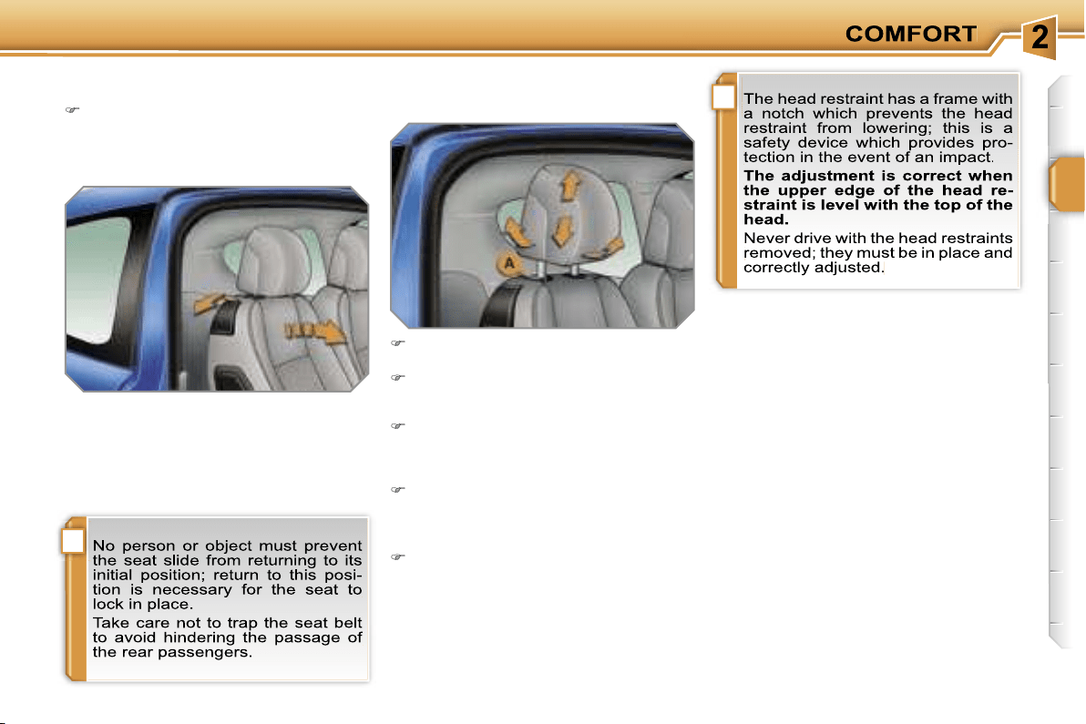
4. Access to rear seats
(3 door and GTi)
Pull the handle to fold the seat back
and move the seat forwards. On re-
positioning, the seat returns to its ini-
tial position.
5. Head restraint height and angle
adjustment (except GTi)
To raise the head restraint, pull it up-
wards.
To remove the head restraint, press
the lug
A
and pull the head restraint
upwards.
To put the head restraint back in po-
sition, locate the stems of the head
restraint in the holes, taking care to
keep them in line with the seat back.
To lower the head restraint, press
the lug
A
and the head restraint at
the same time.
To tilt the head restraint, tilt the lower
part forwards or rearwards.

!
i
56
REAR SEATS
Bench seat the left-hand part (2/3) or
right-hand part (1/3) of which can be
folded to adapt the load space in the
boot.
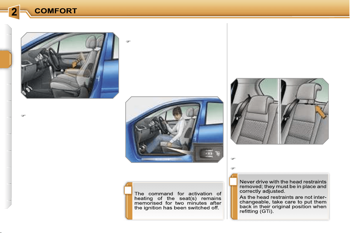
Rear head restraints
These have a high position (comfort)
and a low position (rear visibility).
7. Heated seats switch
With the engine running, the front seats
can be heated separately.
Use the adjustment dial, placed on
the side of each front seat, to switch
on and select the level of heating re-
quired:
0:
Off.
1:
Low.
2:
Medium.
3:
High.
They can also be removed; to remove
them:
pull the head restraint upwards to
the stop,
then, press the lug.
6.
Armrests (except 3 door and GTi)
These can be folded down and are re-
movable.
To remove them, press the button lo-
cated between the armrest and the
side of the seat and pull it.
!
i
56
REAR SEATS
Bench seat the left-hand part (2/3) or
right-hand part (1/3) of which can be
folded to adapt the load space in the
boot.
Rear head restraints
These have a high position (comfort)
and a low position (rear visibility).
7. Heated seats switch
With the engine running, the front seats
can be heated separately.
Use the adjustment dial, placed on
the side of each front seat, to switch
on and select the level of heating re-
quired:
0:
Off.
1:
Low.
2:
Medium.
3:
High.
They can also be removed; to remove
them:
pull the head restraint upwards to
the stop,
then, press the lug.
6.
Armrests (except 3 door and GTi)
These can be folded down and are re-
movable.
To remove them, press the button lo-
cated between the armrest and the
side of the seat and pull it.
!
57
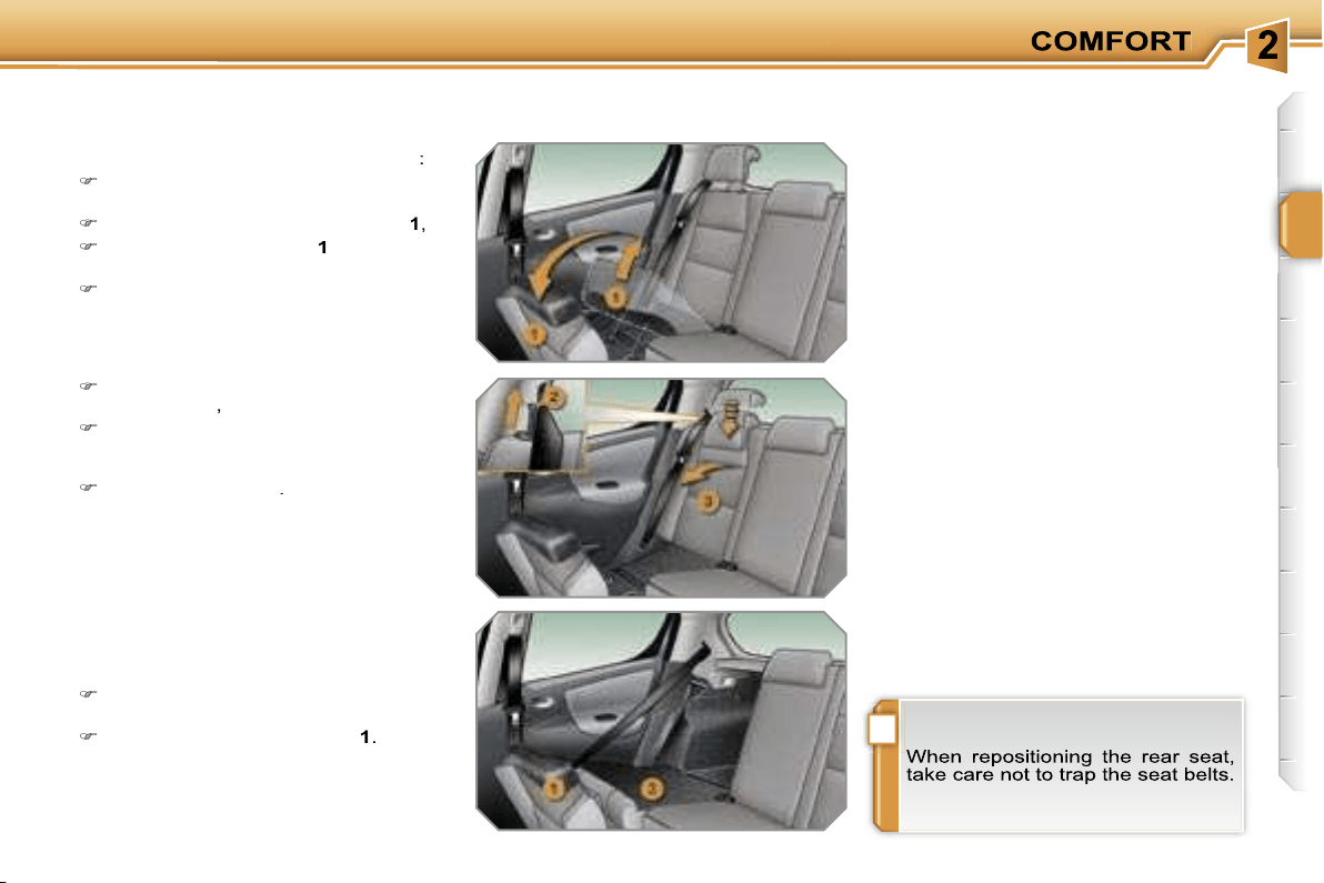
Folding the seat (Saloon)
To fold a rear seat without any risk of
damage to it,
always start with the
seat cushion, never the seat back
:
move the corresponding front seat
forward if necessary,
raise the front of the seat cushion
1
,
tilt the seat cushion
1
against the
front seat,
check that the seat belt is positioned
correctly on the side of the seat
back,
Repositioning the seat
(Saloon)
When repositioning the rear seat:
straighten the seat back
3
and se-
cure it,
fold back the seat cushion
1
.
pull control
2
upwards to release the
seat back
3
,
place the head restraints in the low
position or remove them if neces-
sary,
tilt the seat back
3
.

!
i
56
REAR SEATS
Bench seat the left-hand part (2/3) or
right-hand part (1/3) of which can be
folded to adapt the load space in the
boot.
Rear head restraints
These have a high position (comfort)
and a low position (rear visibility).
7. Heated seats switch
With the engine running, the front seats
can be heated separately.
Use the adjustment dial, placed on
the side of each front seat, to switch
on and select the level of heating re-
quired:
0:
Off.
1:
Low.
2:
Medium.
3:
High.
They can also be removed; to remove
them:
pull the head restraint upwards to
the stop,
then, press the lug.
6.
Armrests (except 3 door and GTi)
These can be folded down and are re-
movable.
To remove them, press the button lo-
cated between the armrest and the
side of the seat and pull it.
!
i
58
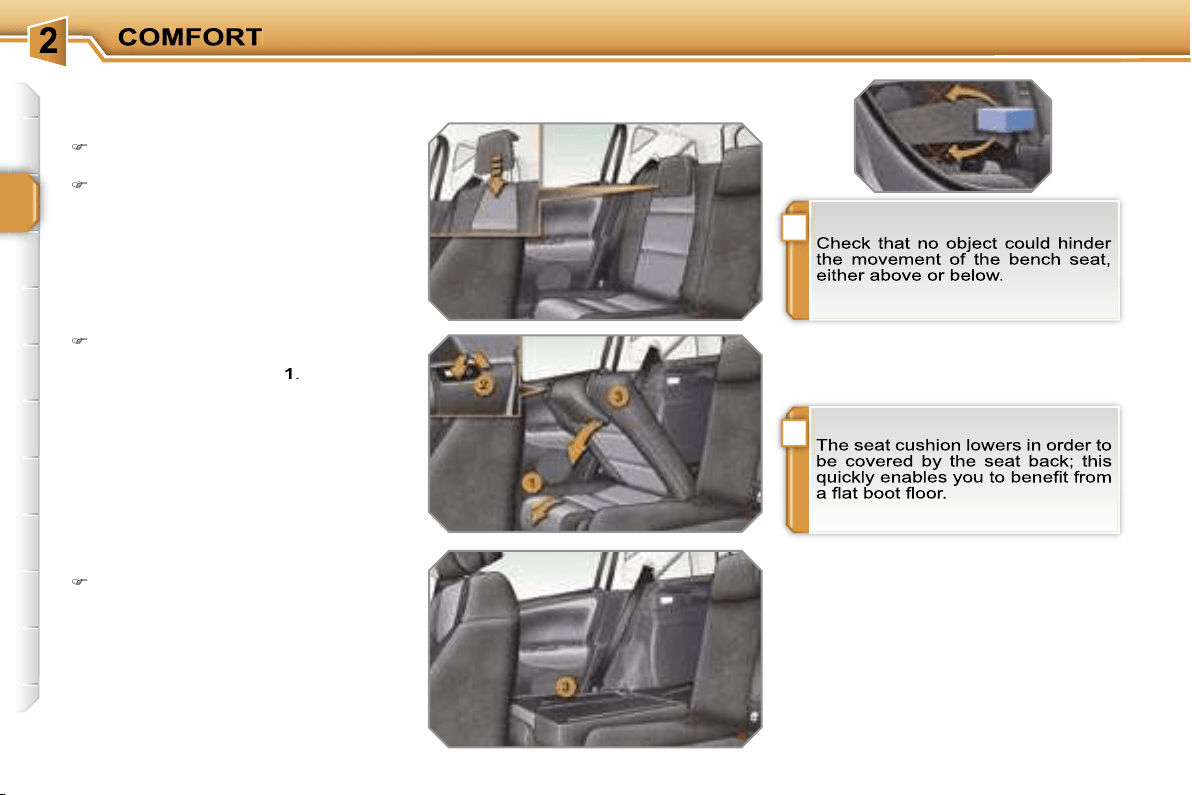
Folding the seat (SW)
To fold a rear seat without any risk of
damage:
move the corresponding front seat
forward if necessary,
place the head restraints in the low
position,
Repositioning the seat (SW)
when repositioning the rear seat,
straighten the seat back
3
and lock
it.
pull the control
2
forward to release
the seat back
3
which folds easily
onto the seat cushion
1
.
i
!
59
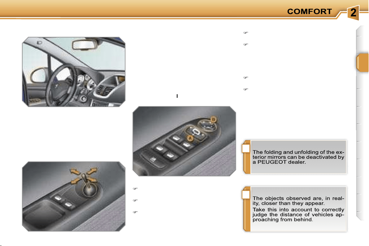
MIRRORS
Exterior mirrors
Adjustable mirror permitting the lateral
rearward vision necessary when over-
taking or parking.
Folding
from outside: lock the vehicle using
the remote control or the key.
from inside: with the ignition on, pull
switch
A
rearwards.
Manual model
Adjustment
Move the lever in all four directions
to direct the mirror correctly.
Folding
When parked, fold the mirror manu-
ally to protect it.
Unfolding
Before starting, unfold the mirror.
Electric mode
l
Adjustment
Slide switch
A
to the right or to the left
to select the corresponding mirror.
Move knob
B
in all four directions to
adjust.
Return switch
A
to the centre
position.
Unfolding
from outside: unlock the vehicle us-
ing the remote control or the key.
from inside: with the ignition on, pull
switch
A
rearwards.
!
i
60
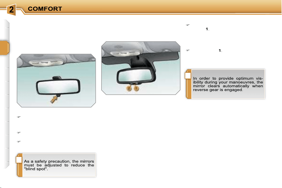
Interior mirror
Adjustable mirror permitting central
rearward vision.
Adjustment
Adjust the mirror to direct it correctly
in the "day" position.
Automatic day/night model
System which automatically and gradu-
ally changes between the day and night
uses.
To avoid glare, the interior mirror dark-
ens automatically in relation to the in-
tensity of the light from the rear.
It clears as soon as the light (light beam
of vehicles behind, sun...) decreases,
so providing optimum visibility.
Switching on
Switch on the ignition and press
switch
1
.
The indicator light
2
comes on and the
mirror operates in automatic mode.
Manual model
The mirror is fitted with a night anti-
dazzle device.
Day/night position
Pull the lever to change to the "night"
anti-dazzle position.
Push the lever to change to the
normal "day" position.
Switching off
Press switch
1
.
The indicator light
2
switches off and
the mirror remains at its clearest.
!
i
61
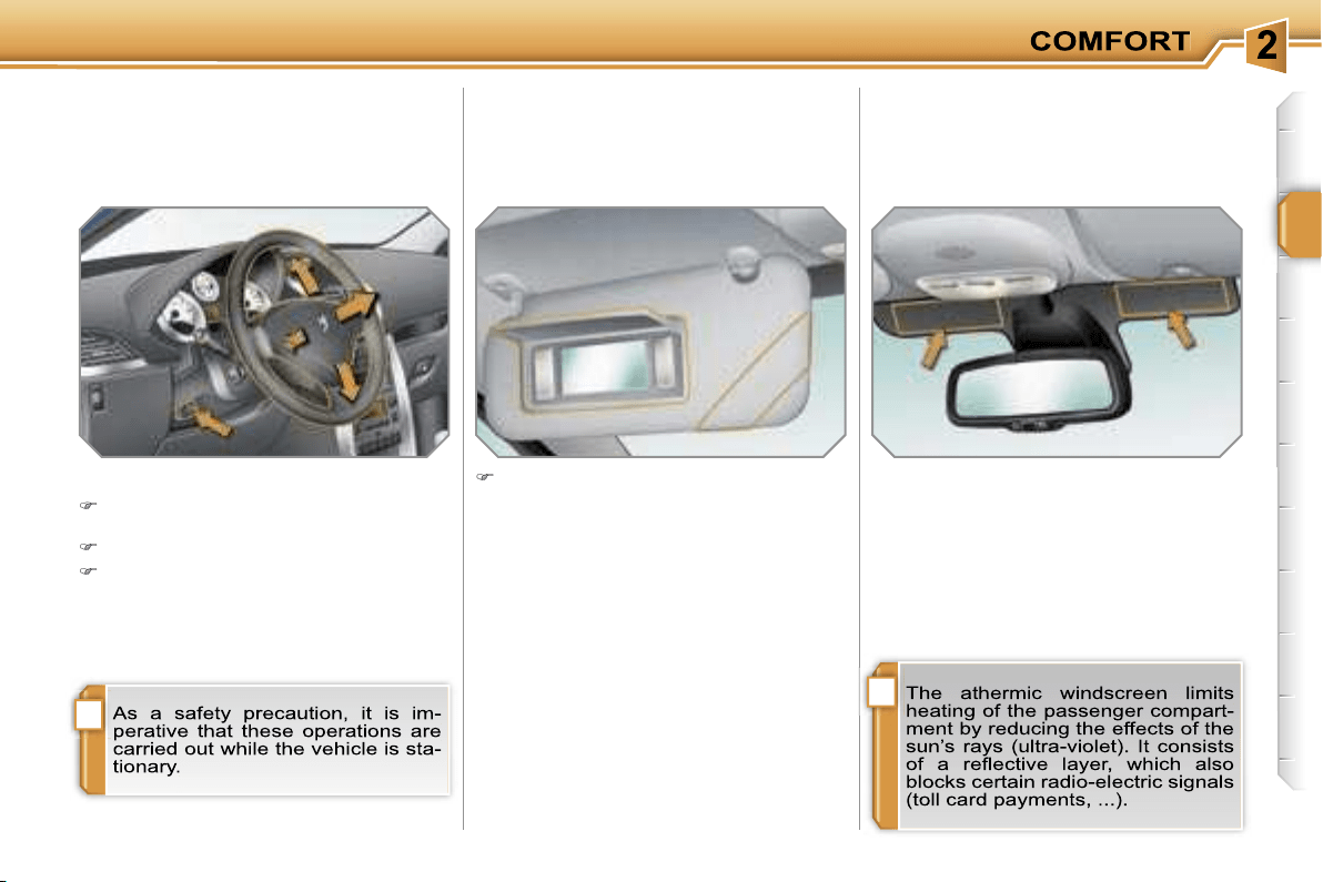
STEERING WHEEL ADJUSTMENT
The height and depth of the steering
wheel can be adjusted to adapt the driv-
ing position to the size of the driver.
Adjustment
When stationary,
pull the control to
unlock the steering wheel.
Adjust the height and depth.
Push the control to lock the steering
wheel.
SUN VISOR
Component which protects against
sunlight from the front or the side, also
equipped with an illuminated courtesy
mirror.
With the ignition on, raise the con-
cealing flap; the mirror is lit automati-
cally.
This sun visor is also equipped with a
ticket holder.
TOLL CARD/CAR PARK TICKET
WINDOWS
Facility for affixing toll cards and/or car
park tickets.
These windows are located on each
side of the base of the interior mirror.
They are two non-reflective areas of the
athermic windscreen.
!
62
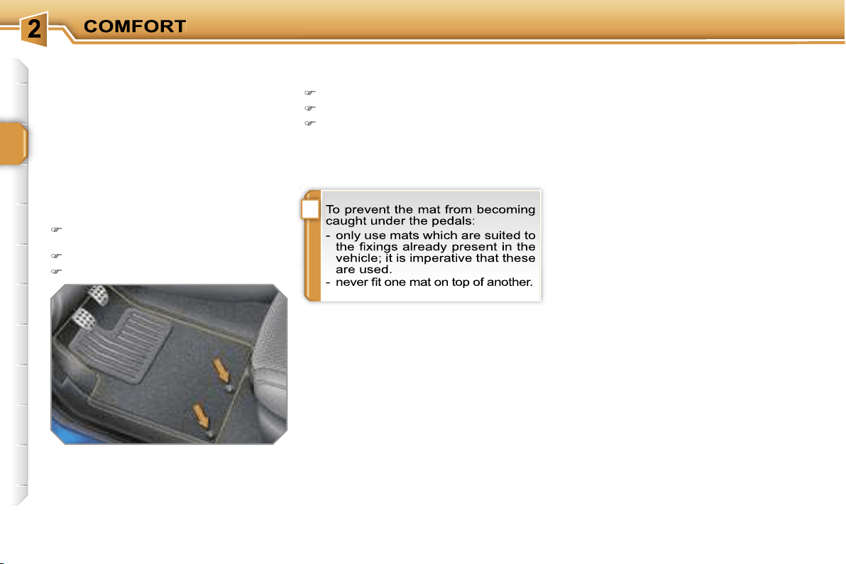
MAT
Removable component which protects
the carpet against exterior dirt.
Refitting
To refit the mat on the driver’s side:
position the mat correctly,
refit the fixings by pressing,
check that the mat is secured
correctly.
Fitting
When fitting the mat for the first time,
use only the fixings provided in the wal-
let attached.
Removal
To remove the mat on the driver’s side:
move the seat as far back as pos-
sible,
unclip the fixings,
remove the fixings, then the mat.
63
INTERIOR LAYOUT
1. Glove box with light
(see details on following page)
2. Storage compartment with
non-slip mat
3. Card holder
4. Door tray
5. Storage compartment with
non-slip mat
6. Ashtray with light/Lighter
(see details on following page)
7. Storage compartments
8. Can holder
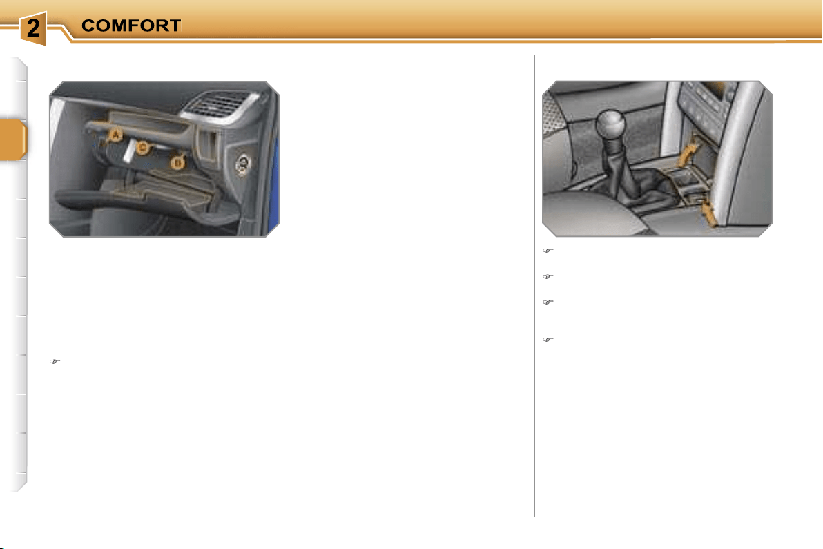
64
Glove box with light
This has an upper open storage com-
partment, a recess and locations for
storing a bottle of water, the vehicle’s
handbook, ...
Its lid has locations for storing a pen,
a pair of spectacles, tokens, cards, a
can, ...
It may be fitted with a lock.
To open the glove box, raise the
handle.
It is lit when the lid is opened.
Ashtray with light/Lighter
Raise the lid to gain access to the
ashtray and the lighter.
To empty the ashtray, after opening,
remove its receptacle.
To use the lighter, press it and wait
a few seconds until it pops out auto-
matically.
To connect a 12 V accessory (max
power: 100 Watts), remove the
lighter and connect the appropriate
adaptor.
It houses the front passenger air bag
disarming switch
A
and three sockets*
B
for connecting audio/video equipment
(refer to the "Audio and Telematics"
section to activate the auxiliary input
sockets).
If the vehicle is fitted with air condi-
tioning, it provides access to the ven-
tilation nozzle
C
, which can be opened
or closed, distributing the same condi-
tioned air as the vents in the passenger
compartment.
* With DT colour display only.
65
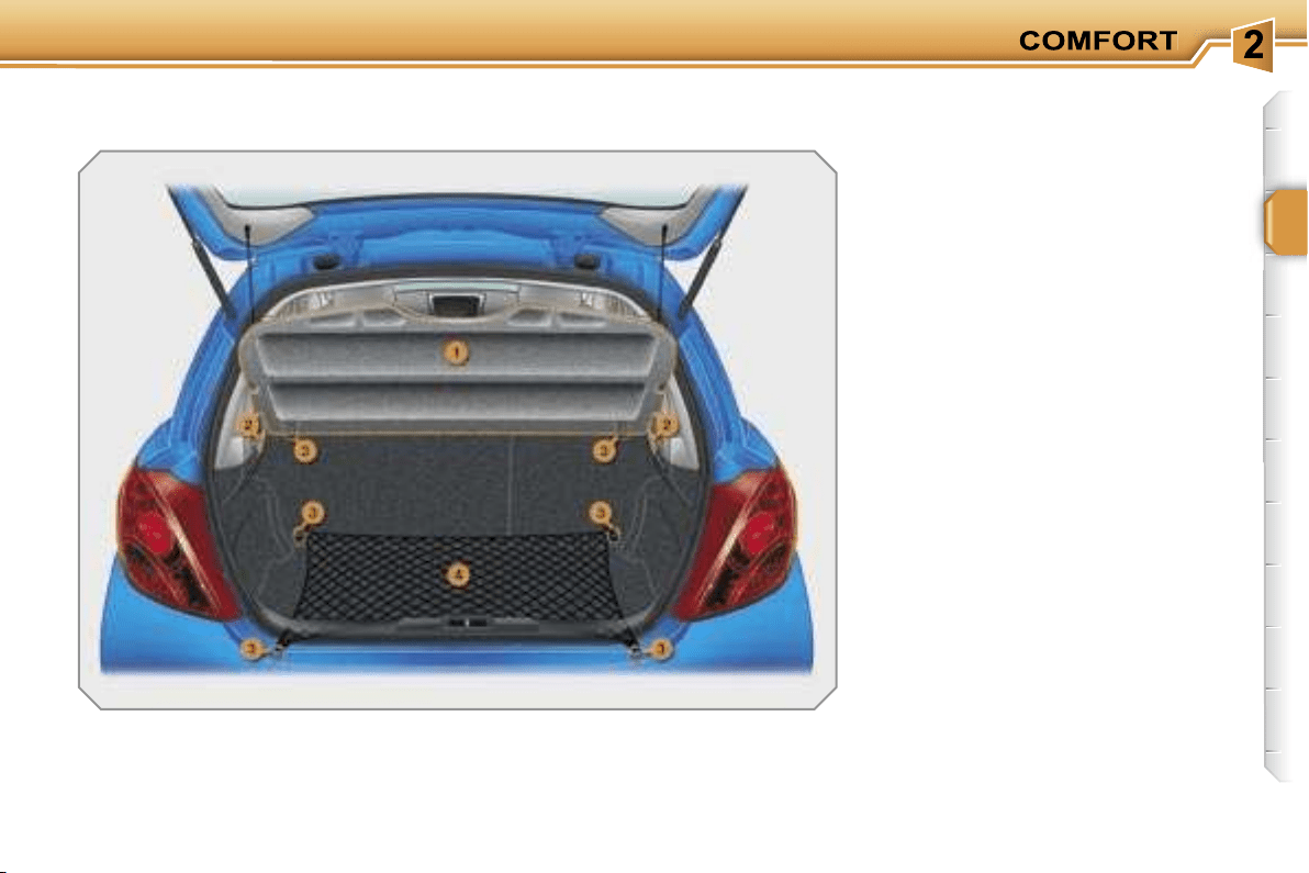
BOOT LAYOUT
(SALOON)
1. Rear shelf
(see details on following page)
2. Hooks
(see details on following page)
3. Stowing rings
4. Luggage retaining net
(see details on following page)
i
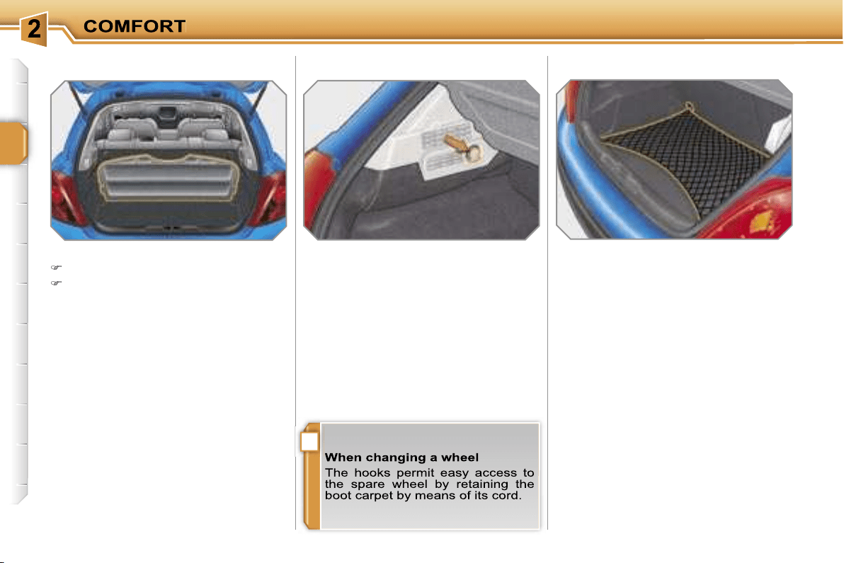
66
Hooks
Hooked onto the stowing rings, this ena-
bles you to secure your luggage, either
to the bottom of the boot or to the back
of the rear seats.
Rear shelf (Saloon)
To remove the shelf:
unhook the two cords,
raise the shelf slightly, then remove
it.
You have two storage options:
- either upright behind the front seats,
- or upright behind the rear seats.
The hooks permit the securing of shop-
ping bags.
Luggage retaining net
67
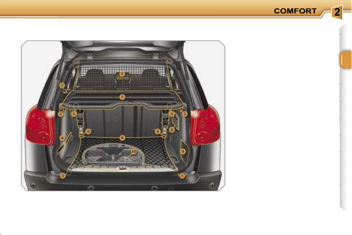
BOOT LAYOUT (SW)
1. Load space cover
(see details on following page)
2. 12 V accessories socket
(see details on following page)
3. Hooks
(see details on previous page)
4. Retaining straps
5. Stowing rings
6. Luggage retaining net
(see details on previous page)
7. High load retaining net
(see details on following page)
8. Storage box
9. Storage net
10. Storage box
(refer to the section "Practical
information - § Changing a wheel")
i
68
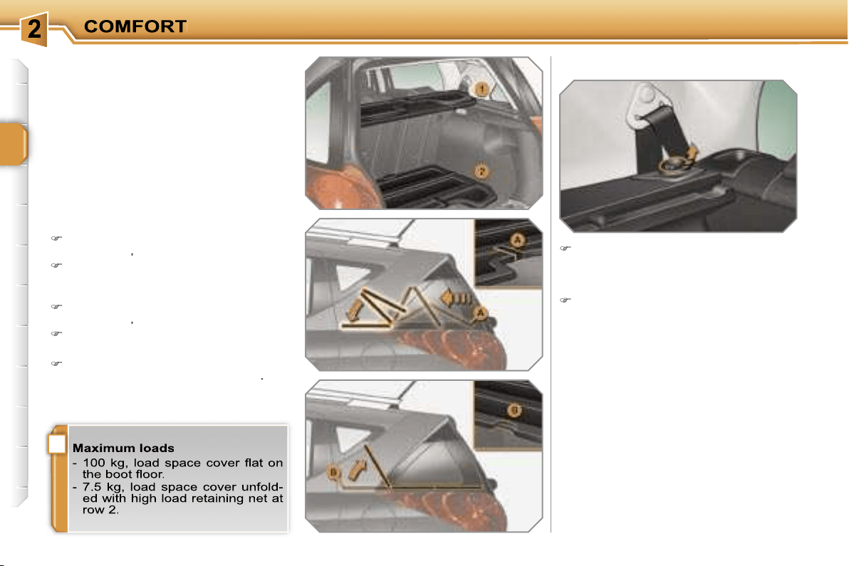
Load space cover (SW)
This consists of three sections which
can be folded back on each other.
There are two storage options:
- either folded on itself near the rear
seats (1),
- or unfolded and placed flat on the boot
floor (2).
To fold it from the boot:
take hold of the load space cover by
its strap
A
,
fold it concertina-style to the rear
seats.
To unfold it from the boot:
take hold of the load space cover by
its strap
A
,
unfold it to the boot pillars.
To gain access from the rear seats:
raise the front section of the load
space cover using the handle
B
.
12 V accessories socket (SW)
In order to connect a 12 V accessory
(max power: 100 Watts), remove
the cap and connect the appropriate
adaptor.
Turn the key to the ignition position.
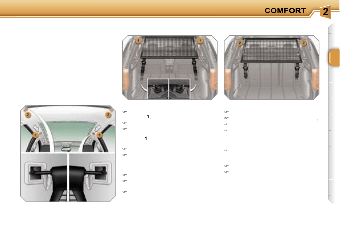
69
High load retaining
net (SW)
Hooked onto the upper fixings and onto
the stowing rings or lugs, this permits
use of the entire loading volume
up to
the roof:
- behind the rear seats (row 2) when
the load space cover is absent,
- behind the front seats (row 1) when
the rear seats are folded.
To use it in row 1:
open the covers of the upper
fixings
1
,
unroll the high load retaining net,
position one of the ends of the net's
metal bar in the corresponding upper
fixing
1
, then do the same with the
other end,
slacken the straps fully,
fix the snap hook of each of the
straps on the corresponding lug,
located under the bench seat cush-
ion,
fold the rear seats,
tighten the straps without raising the
bench seat,
check that the net is hooked and
tightened correctly.
To use it in row 2:
fold or remove the load space cover,
open the covers of the upper fixings
2
,
unroll the high load retaining net,
position one of the ends of the net's
metal bar in the corresponding upper
fixing
2
, then do the same with the
other end,
attach the hook of each of the net's
straps in the corresponding stowing
ring,
tighten the straps,
check that the net is hooked and
tightened correctly.
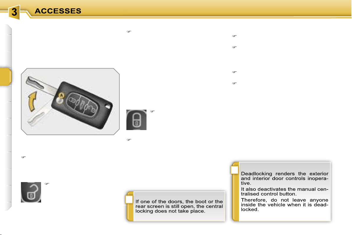
!
i
70
REMOTE CONTROL KEY
System which permits central unlocking
or locking of the vehicle using the lock
or remotely. It also locates and starts
the vehicle, as well as providing protec-
tion against theft.
Unfolding the key
First press button
A
to unfold the
key.
Unlocking the vehicle
Unlocking is confirmed by rapid flashing
of the direction indicators for approxi-
mately two seconds.
According to version, the exterior mir-
rors unfold at the same time.
Locking the vehicle
Normal locking using the remote
control
Deadlocking using the remote
control
Press the closed padlock to lock the
vehicle.
Press the closed padlock again within
five seconds to deadlock the vehicle.
Press the open padlock to
unlock the vehicle.
Unlocking using the key
Turn the key to the left in the driver's
door lock to unlock the vehicle.
Press the closed padlock to
lock the vehicle.
Normal locking using the key
Turn the key to the right in the dri-
ver's door lock to lock the vehicle.
Locking is confirmed by fixed lighting of
the direction indicators for approximate-
ly two seconds.
According to version, the exterior mir-
rors fold at the same time.
Unlocking using the remote
control
Deadlocking using the key
Turn the key to the right in the dri-
ver's door lock to lock the vehicle.
Turn the key to the right again within
five seconds to deadlock the vehicle.
Deadlocking is confirmed by fixed light-
ing of the direction indicators for ap-
proximately two seconds.
According to version, the exterior mir-
rors fold at the same time.

!
i
i
71
Folding the key
First press button
A
to fold the key.
Confidential card
Electronic engine immobiliser
The key contains an electronic chip
which has a special code. When the
ignition is switched on, this code must
be recognised in order for starting to be
possible.
This electronic engine immobiliser locks
the engine management system a few
minutes after the ignition is switched off
and prevents starting of the engine by
anyone who does not have the key.
Anti-theft protection
This is given to you with the duplicate
keys on delivery of your vehicle.
It bears the identification code necessary
for any work on the electronic engine im-
mobiliser by a PEUGEOT dealer.
This code is hidden by a film which
should not be removed until necessary.
In the event of a malfunction,
you are informed by lighting of
this warning light, an audible
signal and a message on the
multifunction display.
In this case, your vehicle does not start;
contact a PEUGEOT dealer as soon as
possible.
Unlocking and partial opening
of the rear screen (SW)
Press this button for more
than two seconds to par-
tially open the rear screen.
This action will unlock the
vehicle first.

i
72
Starting the vehicle
Insert the key in the starter.
Wait a few seconds for the starting
code to be recognised.
Turn the key fully towards the fascia
to position
3 (Starting)
.
When the engine starts, release the
key.
Switching the vehicle off
Immobilise the vehicle.
Turn the key fully towards you to
position
1 (Stop)
.
Remove the key from the starter.
Remote control problem
Following disconnection of the vehicle
battery, replacement of the remote con-
trol battery or in the event of a remote
control malfunction, you can no longer
unlock, lock or locate your vehicle.
First of all, use the key in the lock to
unlock or lock your vehicle.
Then, reinitialise the remote control.
If the problem persists, contact a
PEUGEOT dealer as soon as possible.
Changing the battery
Battery ref.: CR1620/3 volts.
Reinitialisation
Switch off the ignition.
Turn the key to position
2 (Ignition)
.
Press the closed padlock immedi-
ately for a few seconds.
Switch off the ignition and remove
the key from the starter.
The remote control is fully operational
again.
Unclip the casing using a coin at the
notch.
Slide the flat battery out of its loca-
tion.
Slide the new battery into its location
observing the original direction.
Clip the casing.
Reinitialise the remote control.
If the battery is flat, you are in-
formed by lighting of this warn-
ing light, an audible signal and
a message on the multifunction
display.
Locating your vehicle
To locate your vehicle, if you have
locked it, in a car park:
press the closed padlock
,
the cour-
tesy lights come on and the direction
indicators flash for a few seconds.

!
73
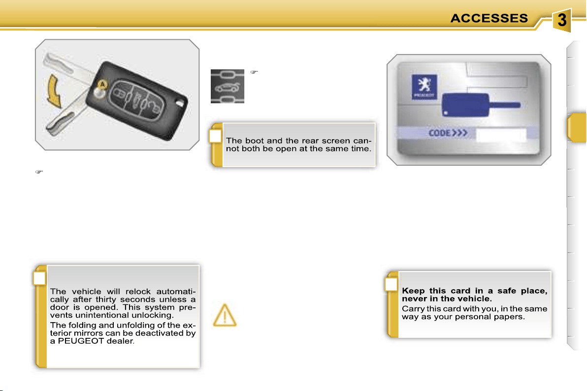
!
i
i
71
Folding the key
First press button
A
to fold the key.
Confidential card
Electronic engine immobiliser
The key contains an electronic chip
which has a special code. When the
ignition is switched on, this code must
be recognised in order for starting to be
possible.
This electronic engine immobiliser locks
the engine management system a few
minutes after the ignition is switched off
and prevents starting of the engine by
anyone who does not have the key.
Anti-theft protection
This is given to you with the duplicate
keys on delivery of your vehicle.
It bears the identification code necessary
for any work on the electronic engine im-
mobiliser by a PEUGEOT dealer.
This code is hidden by a film which
should not be removed until necessary.
In the event of a malfunction,
you are informed by lighting of
this warning light, an audible
signal and a message on the
multifunction display.
In this case, your vehicle does not start;
contact a PEUGEOT dealer as soon as
possible.
Unlocking and partial opening
of the rear screen (SW)
Press this button for more
than two seconds to par-
tially open the rear screen.
This action will unlock the
vehicle first.

i
72
Starting the vehicle
Insert the key in the starter.
Wait a few seconds for the starting
code to be recognised.
Turn the key fully towards the fascia
to position
3 (Starting)
.
When the engine starts, release the
key.
Switching the vehicle off
Immobilise the vehicle.
Turn the key fully towards you to
position
1 (Stop)
.
Remove the key from the starter.
Remote control problem
Following disconnection of the vehicle
battery, replacement of the remote con-
trol battery or in the event of a remote
control malfunction, you can no longer
unlock, lock or locate your vehicle.
First of all, use the key in the lock to
unlock or lock your vehicle.
Then, reinitialise the remote control.
If the problem persists, contact a
PEUGEOT dealer as soon as possible.
Changing the battery
Battery ref.: CR1620/3 volts.
Reinitialisation
Switch off the ignition.
Turn the key to position
2 (Ignition)
.
Press the closed padlock immedi-
ately for a few seconds.
Switch off the ignition and remove
the key from the starter.
The remote control is fully operational
again.
Unclip the casing using a coin at the
notch.
Slide the flat battery out of its loca-
tion.
Slide the new battery into its location
observing the original direction.
Clip the casing.
Reinitialise the remote control.
If the battery is flat, you are in-
formed by lighting of this warn-
ing light, an audible signal and
a message on the multifunction
display.
Locating your vehicle
To locate your vehicle, if you have
locked it, in a car park:
press the closed padlock
,
the cour-
tesy lights come on and the direction
indicators flash for a few seconds.
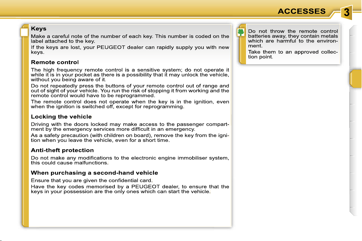
!
73
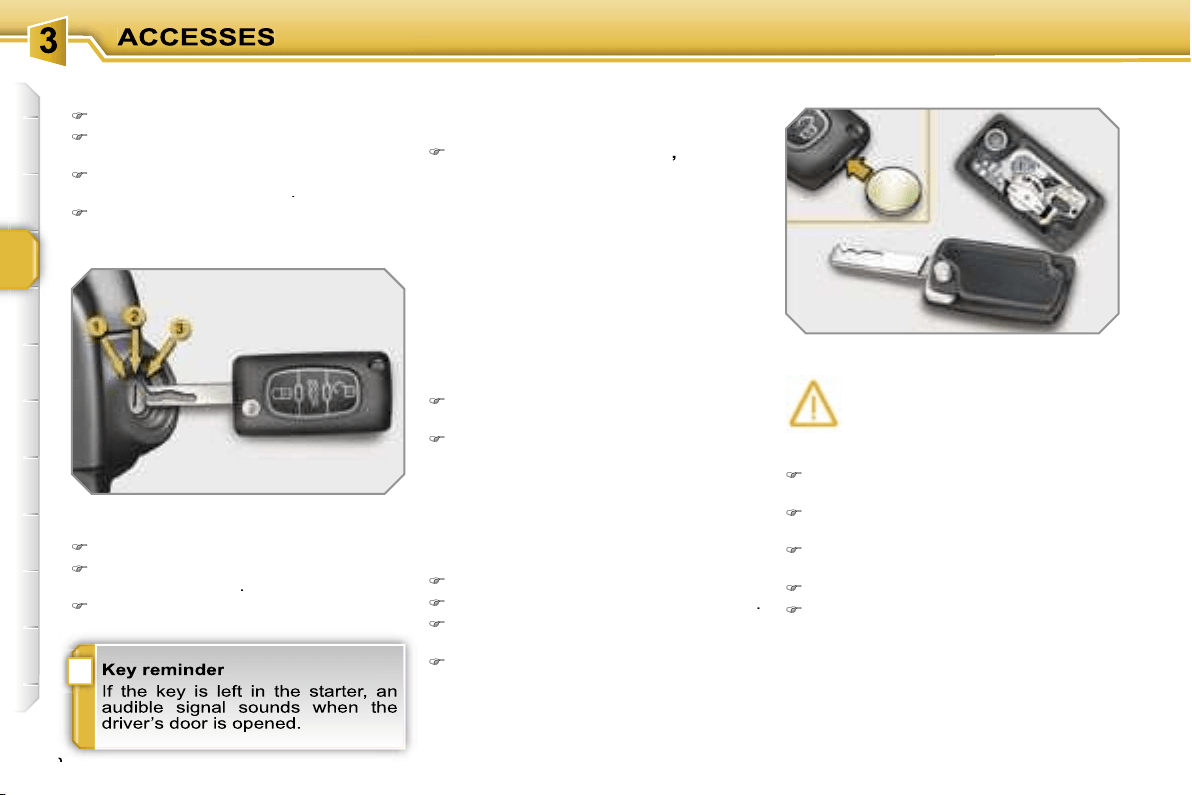
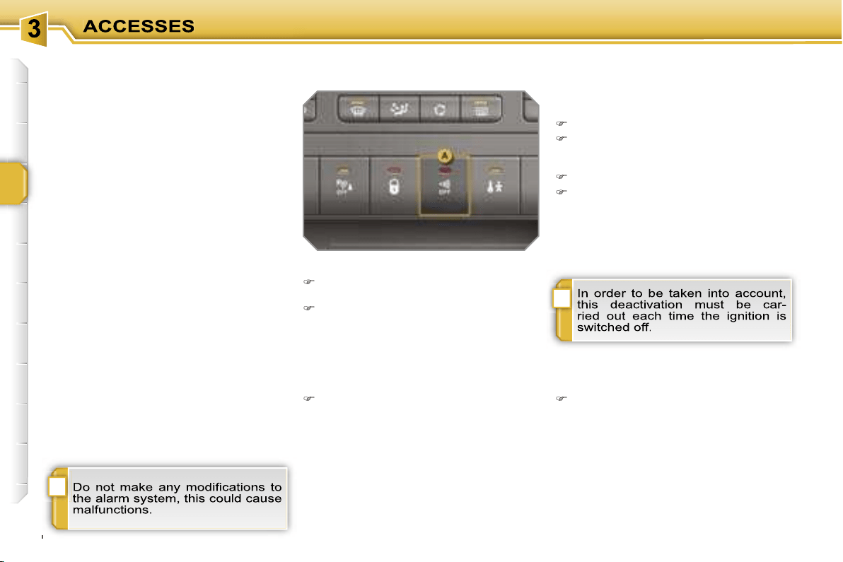
!
i
74
ALARM
System which protects and dissuades
against the theft of your vehicle. It pro-
vides two types of protection, exterior
and interior, as well as an anti-tamper
function.
Locking the vehicle with full
alarm
Reactivation of the interior
protection
Unlock the vehicle using the unlock-
ing button on the remote control.
The alarm is activated again with both
types of protection; the indicator light on
button
A
switches off.
Locking the vehicle with exterior
protection alarm only
Deactivation of the interior
protection
Switch off the ignition.
Within ten seconds, press button
A
until the indicator light is lit continu-
ously.
Get out of the vehicle.
Lock or deadlock the vehicle using
the locking button on the remote
control.
The exterior protection alarm alone re-
mains activated; the indicator light on
button
A
flashes once per second.
Activation
Switch off the ignition and get out of
the vehicle.
Lock or deadlock the vehicle using
the locking button on the remote
control.
The alarm is activated; the indicator light
on button
A
flashes once per second.
Exterior protection
The system detects opening of the
vehicle.
The alarm is triggered if anyone tries to
enter the vehicle by forcing a door, the
boot or the bonnet.
Interior protection
The system detects any variation in the
volume in the passenger compartment.
The alarm is triggered if anyone breaks
a window or moves inside the vehicle.
If you wish to leave a pet in the vehicle
or a window partially open, deactivate
the interior protection.
Anti-tamper function
The system detects the putting out of
service of its components.
The alarm is triggered if anyone tries
to put the wires of the siren, the central
control or the battery out of service.
Deactivation
Unlock the vehicle using the unlock-
ing button on the remote control.
The alarm is deactivated; the indicator
light on button
A
switches off.
!
75
Triggering
This is indicated by sounding of the si-
ren and flashing of the direction indica-
tors for approximately thirty seconds.
After it has been triggered, the alarm is
again operational.
Failure of the remote control
Unlock the vehicle using the key in
the driver’s door lock.
Open the door; the alarm is trig-
gered.
Switch on the ignition; the alarm
stops.
* According to country.
Malfunction
When the ignition is switched on, light-
ing of the indicator light on button
A
for
ten seconds indicates a siren fault.
Contact a PEUGEOT dealer as soon as
possible.
Locking the vehicle without
alarm
Lock or deadlock the vehicle using
the key in the driver’s door lock.
Automatic operation*
Depending on the legislation in force in
your country, one of these cases may
occur:
- 45 seconds after the vehicle is locked
using the remote control, the alarm is
activated, regardless of the status of
the doors and boot.
- 2 minutes after the last door or the
boot is closed, the alarm is activated.
To avoid triggering the alarm on
entering the vehicle, first press the
unlocking button on the remote
control.
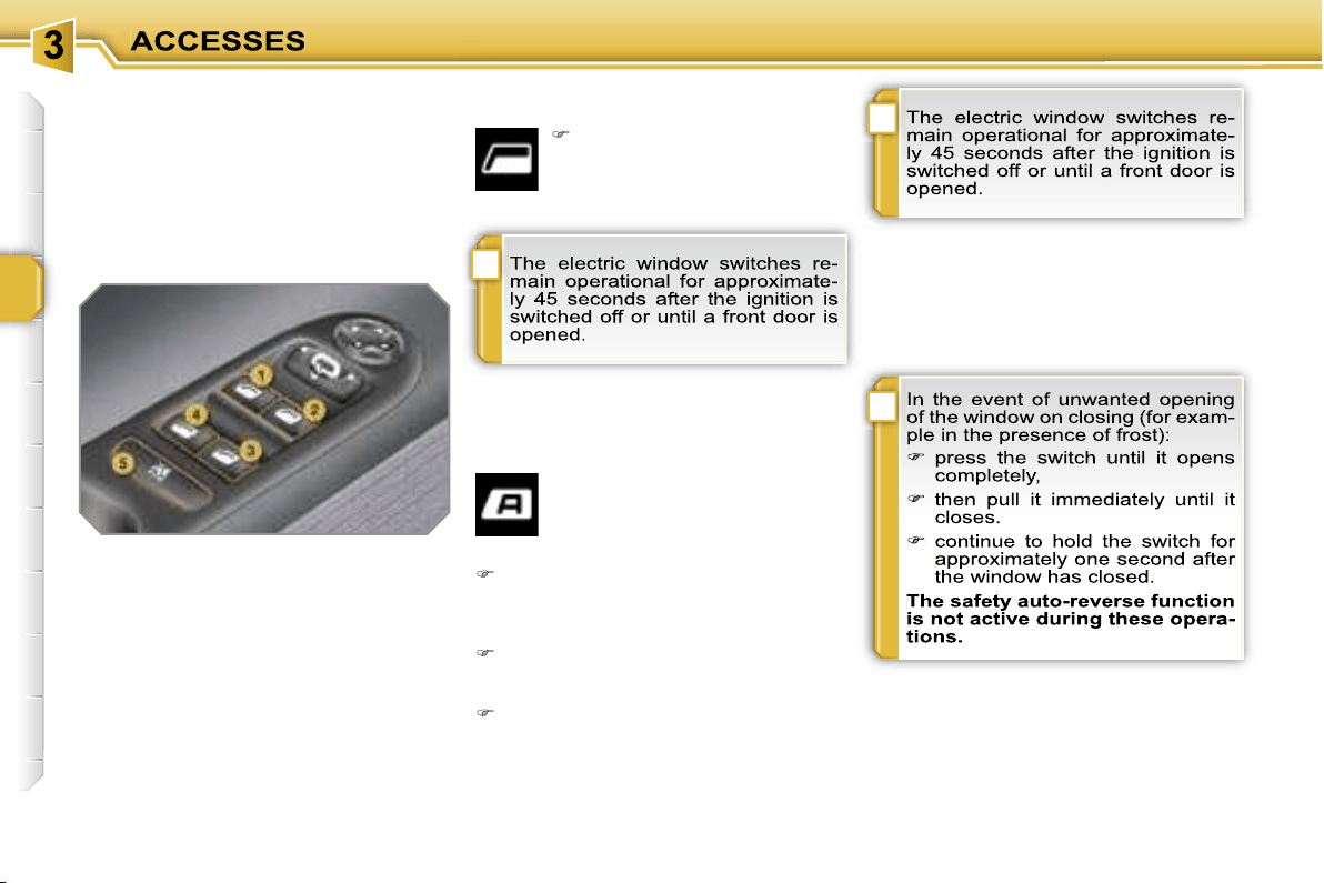
i
i
i
76
WINDOW MECHANISMS
System which opens or closes a win-
dow manually or automatically. It is fit-
ted with a system which provides pro-
tection if an obstacle is detected on the
one-touch models and a deactivation
system to prevent misuse of the rear
switches on all models.
1. Driver’s electric window switch.
2. Passenger’s
electric window
switch.
3.
Rear right electric window
switch.
4. Rear left
electric window switch.
5. Disarming of the rear electric
window switches.
Electric windows
Safety auto-reverse
In automatic mode, when the window
rises and meets an obstacle, it stops
and partially lowers again.
One-touch electric windows
There are two methods of op-
eration:
- manual mode
Press or pull the switch gently. The
window stops as soon as the switch
is released.
- automatic mode
Press or pull the switch fully. The
window opens or closes completely
when the switch is released.
Pressing the switch again stops the
movement of the window.
Press or pull the switch. The
window stops as soon as the
switch is released.

!
77
Disarming the rear window
switches
Reinitialisation
Following reconnection of the battery or
in the event of a malfunction you must
reinitialise the operation of the electric
windows:
release the switch and pull it again
until the window closes completely,
hold the switch for approximately
one second after closing,
REAR QUARTER WINDOWS
On the 3-door versions, system for ven-
tilation of the rear seats limiting the par-
tial opening of the window.
Opening
For the safety of your children, press
switch
5
to prevent operation of the
rear windows irrespective of their
position.
When the button is pressed down,
disarming is active.
When the button is raised, disarming is
deactivated.
Closing
Pull the lever to release the window.
Tilt the lever fully inwards to secure
the window in the closed position.
Tilt the lever outwards.
Push it fully to secure the window in
the open position.
press the switch to lower the window
automatically,
when the window has reached the
low position, press the switch again
for approximately one second.
The safety auto-reverse function is
not active during these operations.
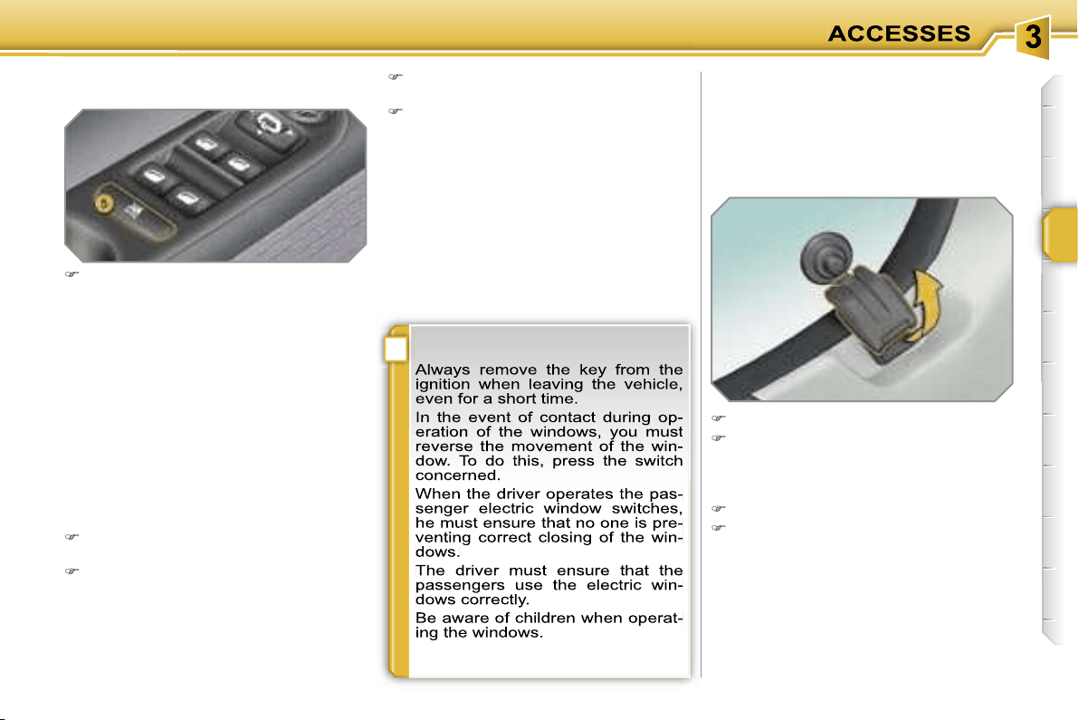
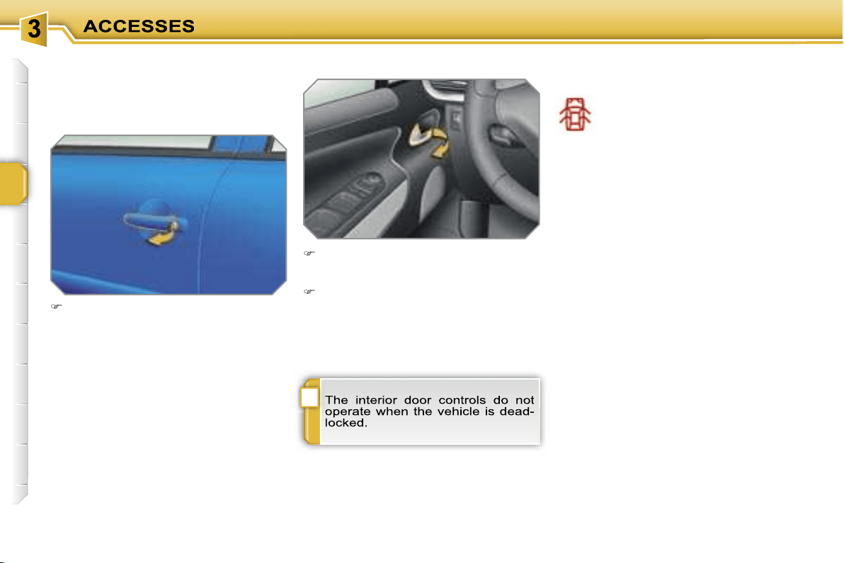
!
78
DOORS
Opening
From outside
After unlocking the vehicle using the
remote control or the key, pull the
door handle.
From inside
Pull the front door control to open the
door; this unlocks the vehicle com-
pletely.
Pull the rear door control to open
the door; this unlocks the door con-
cerned only.
Closing
If a door is not closed correctly:
-
when the engine is running
,
this warning light comes on,
accompanied by a message
on the multifunction display
for a few seconds,
-
when the vehicle is moving
(speed
above 6 mph (10 km/h)), this warn-
ing light comes on, accompanied by
an audible signal and a message
on the multifunction display for a
few seconds.
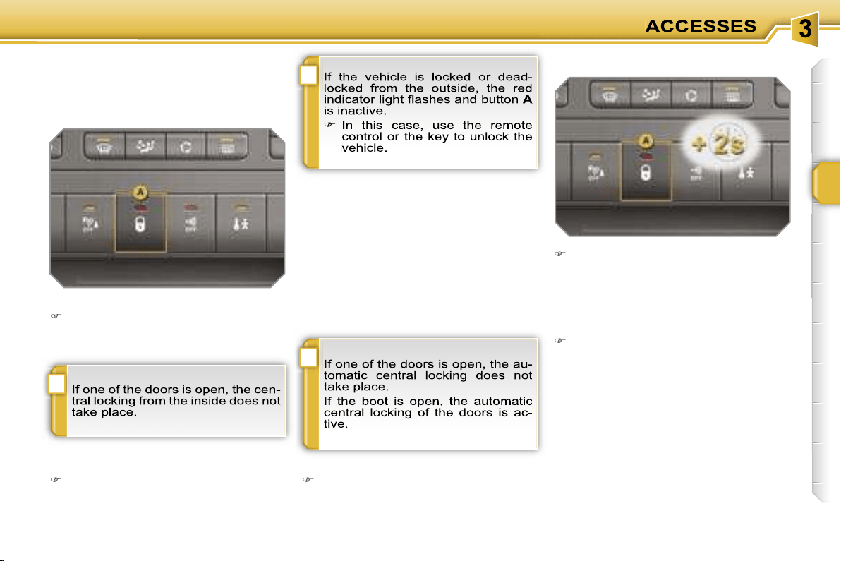
i
!
i
79
Manual centralised control
System which provides full manual
locking or unlocking of the doors from
the inside.
Locking
Press button
A
to lock the vehicle.
The red indicator light on the button
comes on.
Automatic centralised
control
System which provides full automatic
locking or unlocking of the doors and
boot while driving.
You can activate or deactivate this
function.
Activation
Press button
A
for more than
A
A
two seconds.
A confirmation message appears on the
multifunction display.
Unlocking
Above 6 mph (10 km/h), press but-
ton
A
to unlock the doors and boot
temporarily.
Unlocking
Press button
A
again to unlock the
vehicle.
The red indicator light on the button
switches off.
Locking
When the speed exceeds 6 mph (10 km/h),
the doors and boot lock automatically.
Deactivation
Press button
A
again for more than
two seconds.
A confirmation message appears on the
multifunction display.
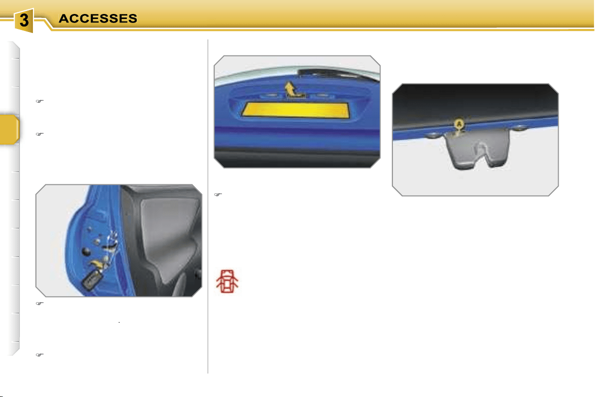
80
Emergency control
System which locks or unlocks the doors
mechanically in the event of a malfunc-
tion of the central locking.
Insert the key in the lock, located on
the edge of the door, then turn it
one
eighth of a turn
.
Tailgate release
System for mechanical unlocking of the
boot in the event of a central locking
malfunction.
Unlocking
Fold back the rear seats to gain
access to the lock
from inside the
boot.
Insert a small screwdriver into hole
A
of the lock to unlock the tailgate.
Locking the driver’s door
Insert the key in the lock, then turn it
to the right.
Unlocking the driver’s door
Insert the key in the lock, then turn it
to the left.
Locking the front and rear
passenger doors
Unlocking the front and rear
passenger doors
Pull the interior door opening control.
Opening
After unlocking the vehicle using the
remote control or the key, pull the
handle and raise the tailgate.
BOOT (SALOON)
-
when the engine is running
,
this warning light comes on,
accompanied by a message
on the multifunction display
for a few seconds,
-
when the vehicle is moving
(speed
above 6 mph (10 km/h)), this warn-
ing light comes on, accompanied by
an audible signal and a message on
the multifunction display for a few sec-
onds.
Closing
If the tailgate is not closed correctly:
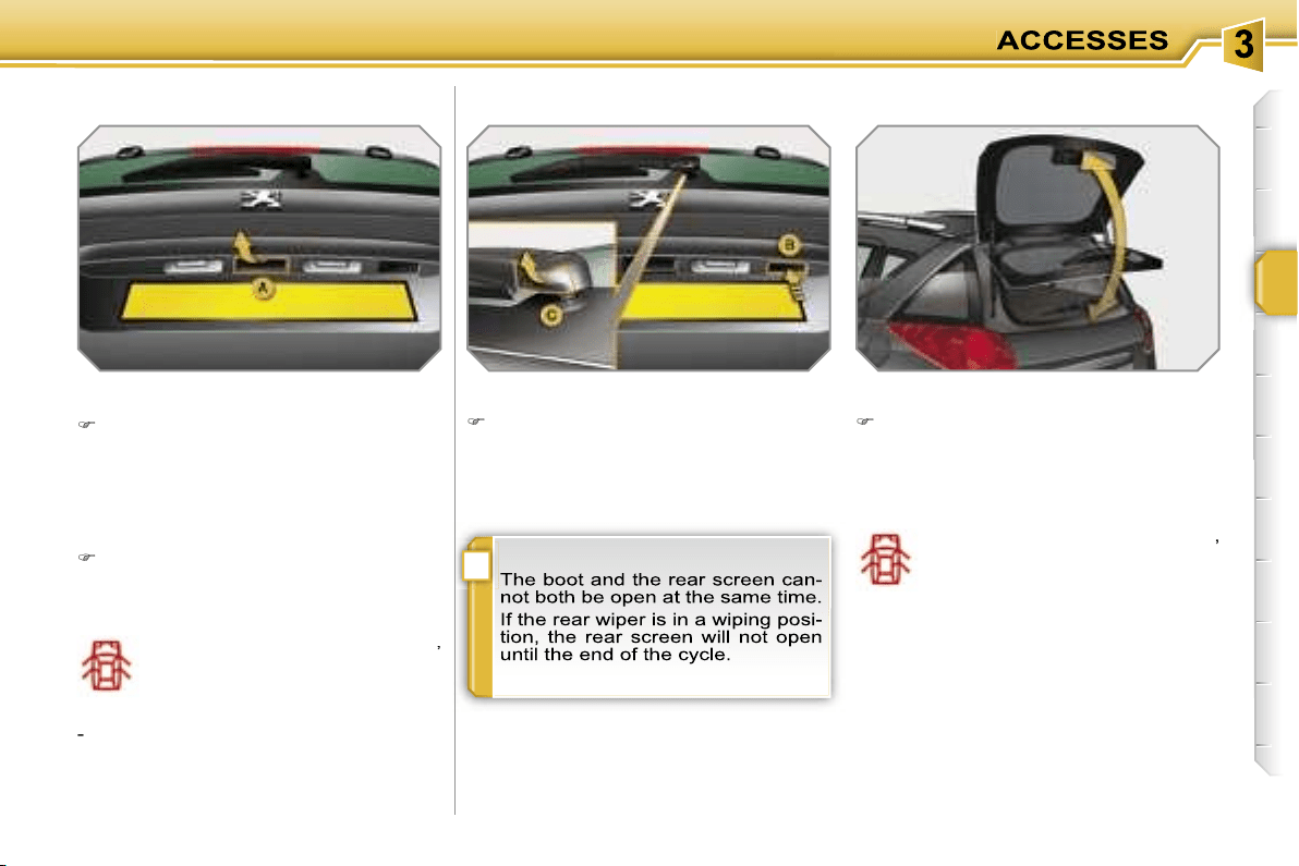
i
81
Opening
After unlocking the vehicle using the
remote control or the key, with the
rear screen closed, pull on the han-
dle
A
and raise the tailgate.
-
when the engine is running
,
this warning light comes on,
accompanied by a message
on the multifunction display
for a few seconds,
-
when the vehicle is moving
(speed
above 6 mph (10 km/h)), this warning
light comes on, accompanied by an au-
dible signal and a message on the mul-
tifunction display for a few seconds.
Closing
Lower the tailgate using the interior
grab handle.
If the tailgate is not closed correctly:
REAR SCREEN (SW)
Opening
After unlocking the vehicle using the
remote control or the key, with the
boot closed, press on the handle
B
and raise the rear screen using the
base
C
of the wiper arm.
Closing
Close the rear screen by pressing at
the centre of the glass.
If the rear screen is not closed correctly:
-
when the engine is running
,
this warning light comes on,
accompanied by a message
on the multifunction display
for a few seconds,
-
when the vehicle is moving
(speed
above 6 mph (10 km/h)), this warning
light comes on, accompanied by an au-
dible signal and a message on the mul-
tifunction display for a few seconds.
BOOT (SW)
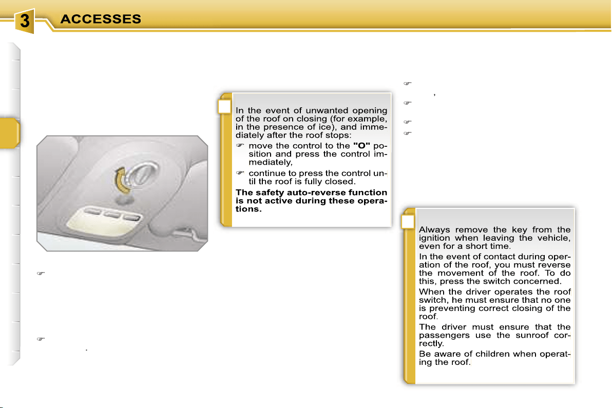
i
!
82
SUNROOF (SALOON)
System which improves the ventilation
and light in the passenger compartment.
It is fitted with a system which provides
protection if an obstacle is detected and
a shutter to maintain a comfortable tem-
perature.
Opening
Turn the control to the left (nine pos-
sible settings).
A deflector gradually unfolds on open-
ing to prevent unwanted gusts of air.
Safety auto-reverse
When the sunroof is closing and meets
an obstacle, it stops then partially opens
again.
Reinitialisation
If a malfunction occurs following recon-
nection of the battery, the sunroof must
be reinitialised:
place the control in the initial position
"O"
,
press the centre of the control for
more than two seconds,
wait until the roof closes completely,
then, the sunroof opens again by a
few millimetres.
The safety auto-reverse function is
not active during these operations.
Shutter
The sunroof shutter is manual.
It is stored automatically when the roof
is opened.
Operation
Closing
Return the control to the initial posi-
tion
"O"
.
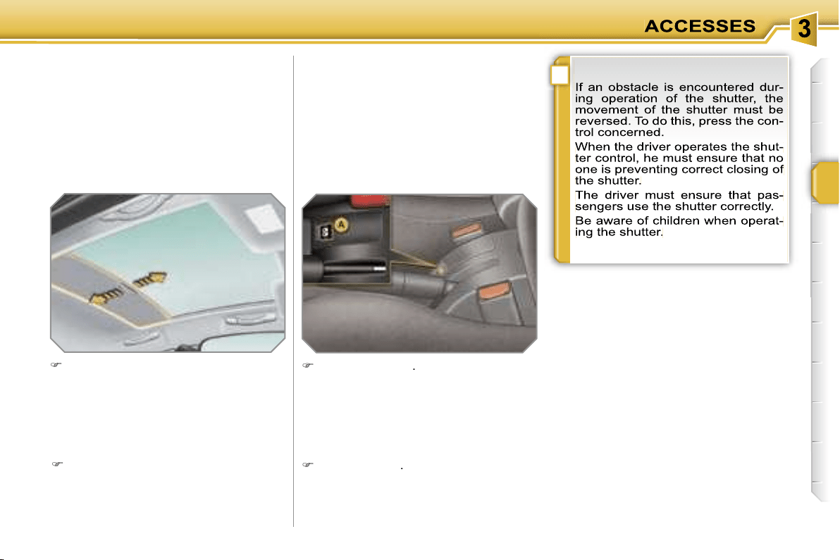
!
83
PANORAMIC ROOF
(SALOON)
System which consists of a panoramic
surface of tinted glass to increase the
light and visibility in the passenger com-
partment. It is fitted with a manual shut-
ter in two parts to maintain a comfortable
temperature.
Take the shutter by its handle and
push it rearwards to the required po-
sition.
Opening
Closing
Take the shutter by its handle and
pull it forwards to the required
position.
PANORAMIC ROOF (SW)
System which consists of a panoramic
surface of tinted glass to increase the
light and visibility in the passenger
compartment. It is fitted with an electric
shutter in two parts to maintain a com-
fortable temperature.
Opening
Press control
A
.
The shutter stops when the control is
released.
Closing
Pull control
A
.
The shutter stops when the control is
released.
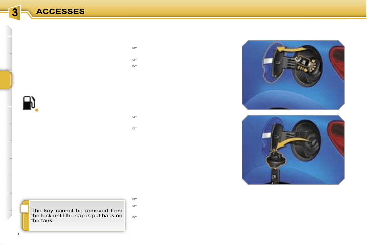
i
84
FUEL TANK
Reservoir which should be refilled with
fuel, when the minimum level has been
detected.
Fuel tank capacity: approximately
50 litres.
To fill the tank in complete safety:
it is imperative that the engine is
switched off,
open the fuel filler flap,
insert the key in the cap, then turn it
to the left,
When you have filled the tank:
put the cap back in place,
turn the key to the right, then remove
it from the cap,
close the flap.
remove the cap and hook it onto the
clip located on the inside of the flap,
fill the tank, but
do not continue af-
ter the 3rd cut-off of the pump
; this
could cause malfunctions.
Low fuel level
Filling
A label affixed to the inside of the flap
reminds you of the type of fuel to be
used depending on your engine.
When the fuel tank minimum level
is reached, this warning light comes
on on the instrument panel.
The distance which can be
travelled with the fuel remaining is
approximately 30 miles (50 km).
If you run out of fuel, refer also to the
"Practical information" section.
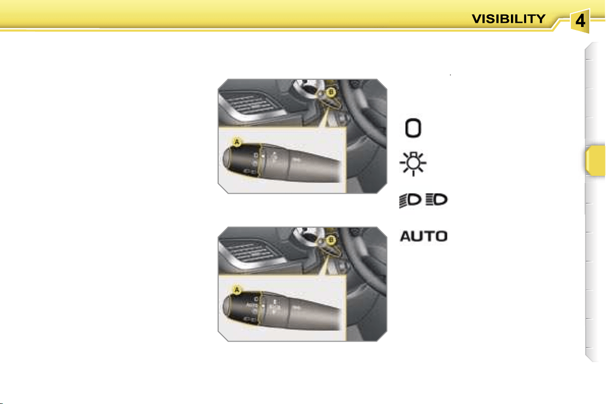
85
LIGHTING CONTROLS
System for selection and control of the
various front and rear lights providing
the vehicle’s lighting.
Manual controls
The lighting commands are made di-
rectly by the driver by means of ring
A
and lever
B
.
lights off,
side lights only,
dipped or main beam
headlamps,
B.
lever for inversion of the lights by
pulling: dipped headlamps/main
beam headlamps.
In the lights off and side lights modes,
the driver can switch on the main beam
headlamps directly ("headlamp flash")
for as long as he pulls the lever.
Displays
The corresponding indicator light comes
on on the instrument panel to confirm
the selective switching on of the lighting
selected.
Main lighting
The vehicle’s various front and rear
lights are designed to adapt the driver’s
visibility gradually in relation to the cli-
matic conditions:
- side lights, to be seen,
- dipped headlamps to see without dazz-
ling other drivers,
- main beam headlamps for good vis-
ibility when the road is clear.
Additional lighting
Other lights are installed to respond to
particular driving conditions:
- rear fog lamps to be seen from a dis-
tance,
- front fog lamps for even better visibil-
ity,
- directional headlamps for improved
visibility around bends.
Programmes
Various automatic lighting control
modes are also available according to
the following options:
- "follow-me-home" lighting,
- automatic lighting,
- static directional lighting.
A.
main lighting mode selection ring,
with:
Model without AUTO lighting
Model with AUTO lighting
automatic lighting.
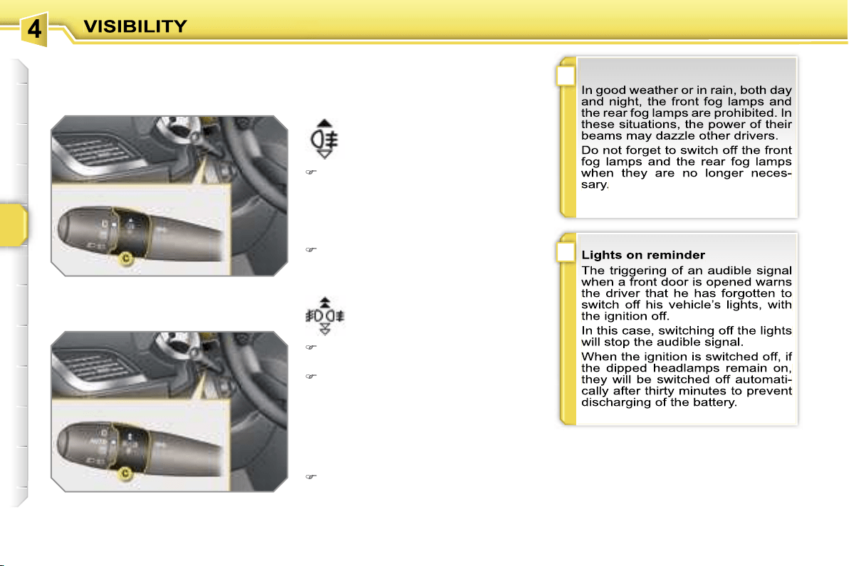
!
i
86
Model with rear fog lamps only
Model with front and rear fog lamps
front and rear fog lamps
rear fog lamps
C.
fog lamps selection ring.
These operate with the dipped and main
beam headlamps.
To switch on the fog lamps, turn push
ring
C
forwards.
When the lights are switched off au-
tomatically (on AUTO model), the fog
lamps and the dipped headlamps will
remain on.
To switch off all of the lights, turn
push ring
C
rearwards.
To switch on the fog lamps, turn push
ring
C
forwards.
To switch off the rear fog lamps, turn
push ring
C
rearwards twice in suc-
cession.
When the lights are switched off auto-
matically (on AUTO model) or when
the dipped headlamps are switched off
manually, the fog lamps and the side
lights will remain on.
Turn the ring rearwards to switch
off the fog lamps, the side lights will
then switch off.

!
87
Coupling with the "Follow-me-
home" lighting
Association with the automatic lighting
provides the "follow-me-home" lighting
with the following additional options:
- selection of the duration of maintaining
of the lighting for 15, 30 or 60 seconds
in the vehicle parameters on the multi-
function display configuration menu,
- automatic activation of "follow-me-
home" lighting when the automatic
lighting is in operation.
Automatic lighting
The side lights and dipped headlamps
are switched on automatically, without
any action on the part of the driver,
when a low level of external light is de-
tected (sensor behind the interior mir-
ror) or when the windscreen wipers are
switched on.
As soon as the brightness returns to a
sufficient level or the windscreen wipers
are switched off, the lights are switched
off automatically.
"Follow-me-home" lighting
The dipped headlamps remain on tem-
porarily, after switching off the vehicle’s
ignition, to make the driver’s exit easier
in poor light.
Activation
With the ignition off, activate a "head-
lamp flash" using lever
B
.
A second "headlamp flash" switches
the function off again.
Switching off
The "follow-me-home" lighting is
switched off automatically following the
door locking command, after a given
time.
Activation
Turn ring A to the "AUTO" position.
The automatic lighting is accompa-
nied by a message on the multifunc-
tion display.
Operating fault
In the event of a malfunction of
the brightness sensor, the lights
come on accompanied by the
service warning light, an audi-
ble signal and a message on the multi-
function display.
In this case, contact a PEUGEOT dealer.
Daytime lights*
On vehicles fitted with daytime lights,
the dipped headlamps come on when
the vehicle is started.
* According to country.
This indicator light comes on
on the instrument panel.
The instruments and controls (instru-
ment panel, multifunction display, air
conditioning control panel, ...) are not
lit, unless the automatic switching on of
the lights mode is activated or the lights
are switched on manually.
Deactivation
Turn ring A to a position other than
"AUTO". Deactivation is accompa-
nied by a message on the multifunc-
tion display.
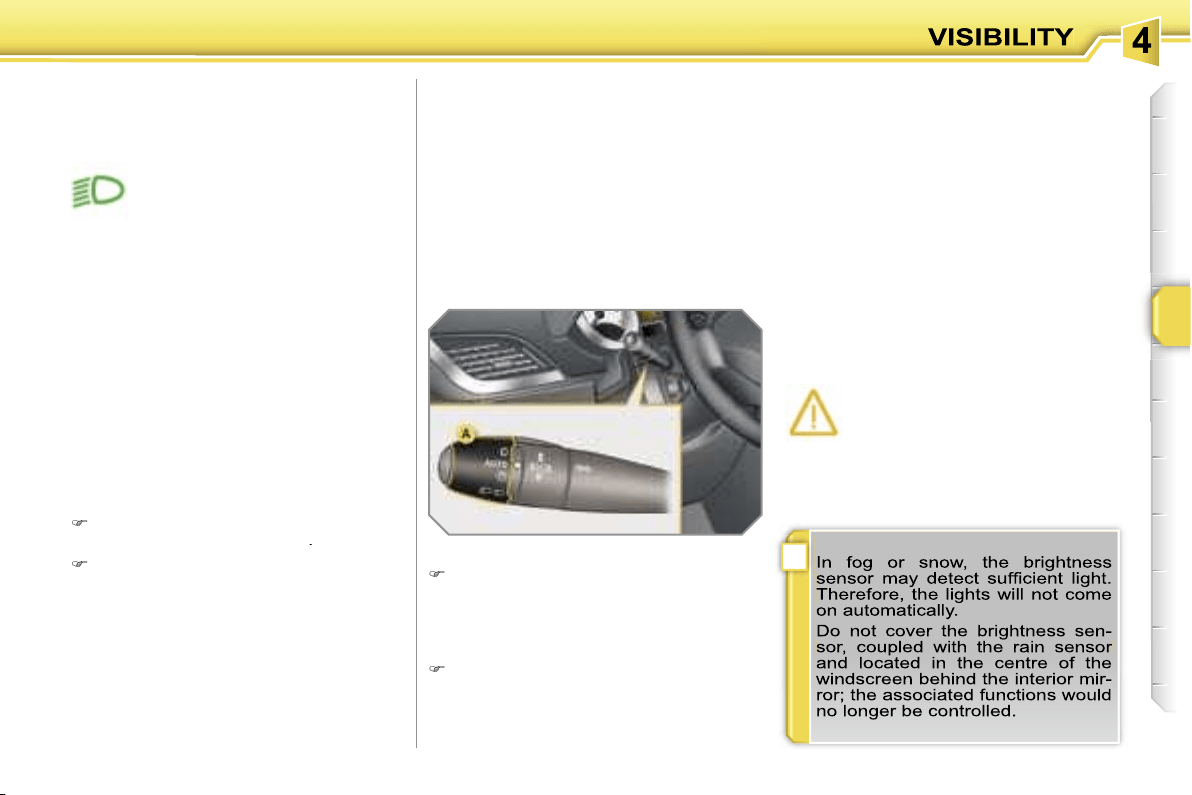
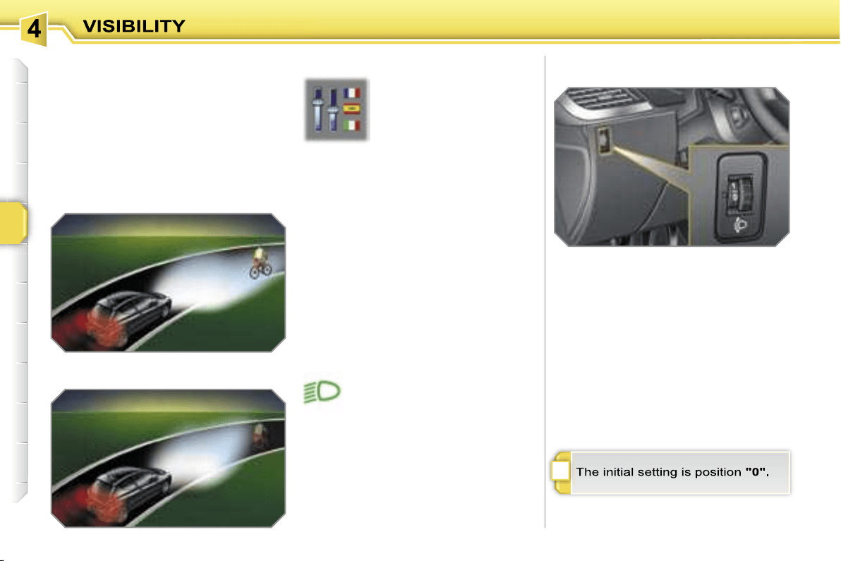
i
88
STATIC DIRECTIONAL
LIGHTING
When the dipped or main beam head-
lamps are on, this function enables the
beam to light the inside of the turn with an
additional angle of approximately 30°.
The use of this lighting is optimum
above all at low and average speed
(city driving, winding roads, ...).
with directional lighting
without directional lighting
Programming
Switching on
The system is switched on from a cer-
tain speed and a certain angle of rota-
tion of the steering wheel.
Operating fault
The function is activated or
deactivated via the multi-
function display configura-
tion menu.
By default, this function is
activated.
In the event of a malfunction,
this warning light flashes on the
instrument panel, accompanied
by a message on the multifunc-
tion display.
HEADLAMP ADJUSTMENT
To avoid causing a nuisance to other
road users, the height of the headlamps
should be adjusted in relation to the
load in the vehicle.
0.
1 or 2 people in the front seats.
-.
3 people.
1.
5 people.
2.
5 people + maximum authorised
load.
3.
Driver + maximum authorised load.
Switching off
The system is switched off below a certain
angle of rotation of the steering wheel.
It is switched off when reverse gear is
engaged.
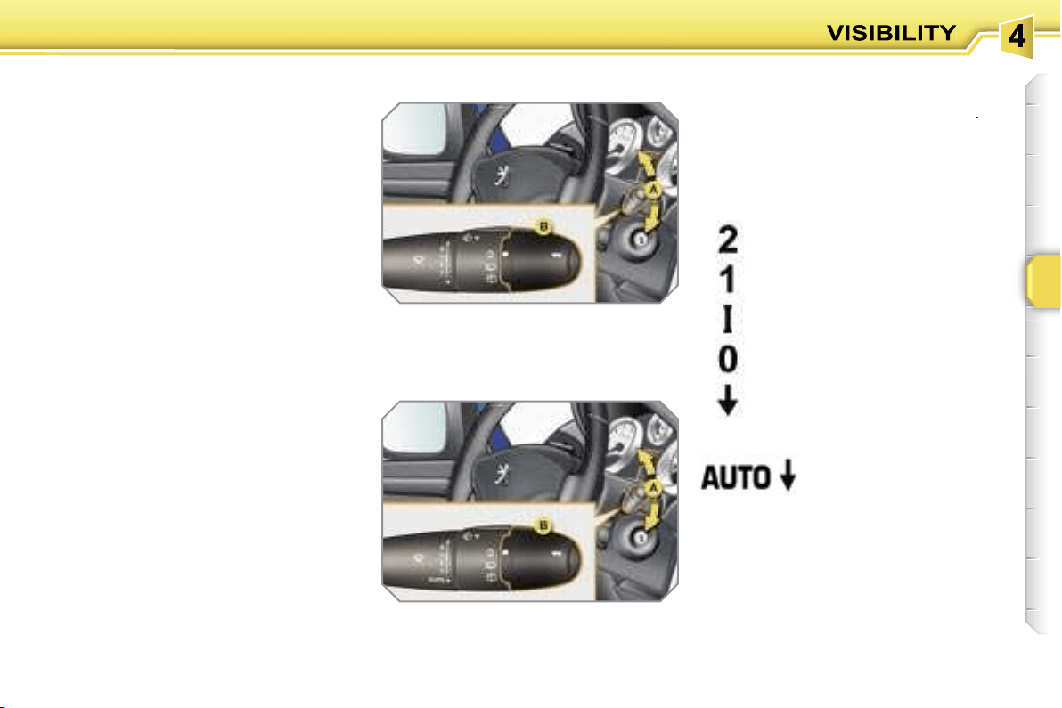
89
WIPER CONTROLS
System for the selection and control of
the various front and rear wiping modes
permitting the dispersal of rain and
cleaning.
The vehicle’s various front and rear wip-
ers are designed to gradually improve
the driver’s visibility in relation to the
weather conditions.
Manual controls
The wiping commands are made directly
by the driver using lever
A
and ring
B
.
Model with intermittent wiping
Model with AUTO wiping
fast (heavy rain),
normal (moderate rain),
intermittent (in proportion to
the speed of the vehicle),
automatic (refer to the
following page).
off,
single wipe (press downwards),
Programmes
Various automatic wiping control modes
are also available depending on the fol-
lowing options:
- automatic windscreen wiping,
- rear wiping on engaging reverse gear.
Windscreen wipers
A.
wiping speed selection lever:
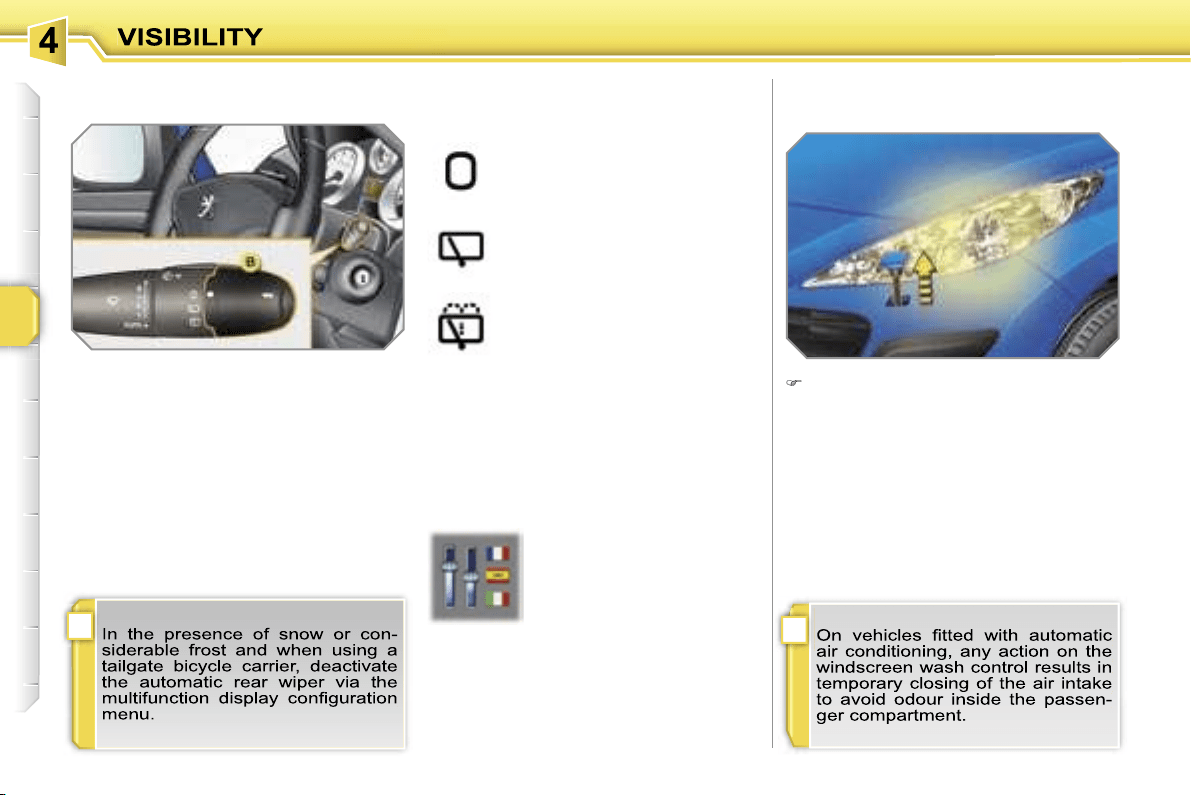
!
i
90
Windscreen and headlamp wash
B.
rear wiper selection ring:
off,
intermittent wipe,
wiping with screenwash (fixed
duration).
Reverse gear
When reverse gear is engaged, if the
windscreen wipers are operating, the
rear wiper will start.
Programming
Pull the windscreen wiper stalk to-
wards you. The windscreen wash
then the windscreen wipers operate
for a fixed period.
The headlamp wash is also activated,
if
the dipped headlamps are on.
Rear wiper
The function is activated or
switched off via the multi-
function display configura-
tion menu.
By default, this function is
activated.
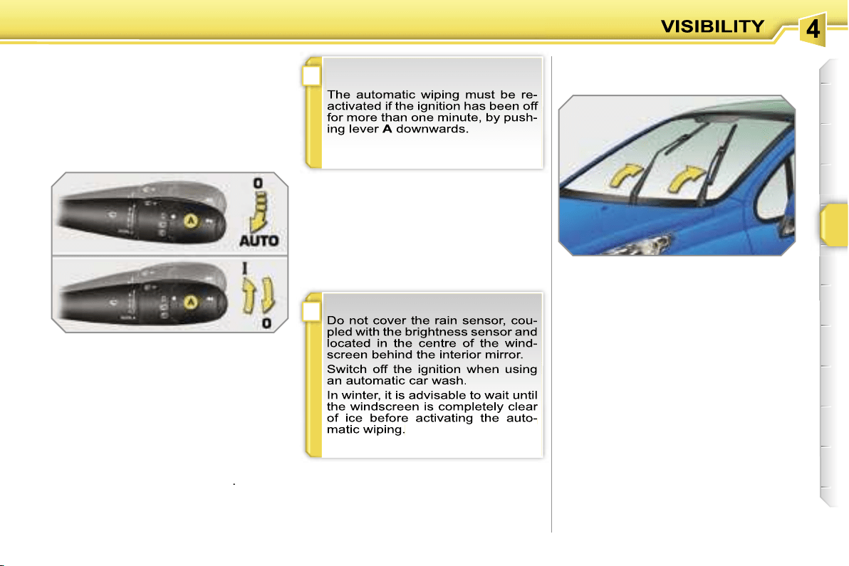
!
i
91
Special position of the
windscreen wipers
Automatic windscreen wiping
The windscreen wipers operate automati-
cally, without any action on the part of the
driver, if rain is detected (sensor behind
the interior mirror), adapting their speed
to the intensity of the rainfall.
Activation
This is controlled manually by the driver
by pushing lever
A
to the
"AUTO"
posi-
tion.
It is accompanied by a message on the
multifunction display.
In the minute following switching off of
the ignition, any action on the stalk po-
sitions the wipers in the centre of the
windscreen.
This action enables you to position the
wiper blades for winter parking.
To park the wipers after this has been
done, switch on the ignition and operate
the stalk.
Switching off
This is controlled manually by the driver
by moving lever
A
to another position
and returning it to position
"0"
.
It is accompanied by a message on the
multifunction display.
Operating fault
If an automatic wiping malfunction oc-
curs, the wipers will operate in intermit-
tent mode.
Contact a PEUGEOT dealer to have the
system checked.
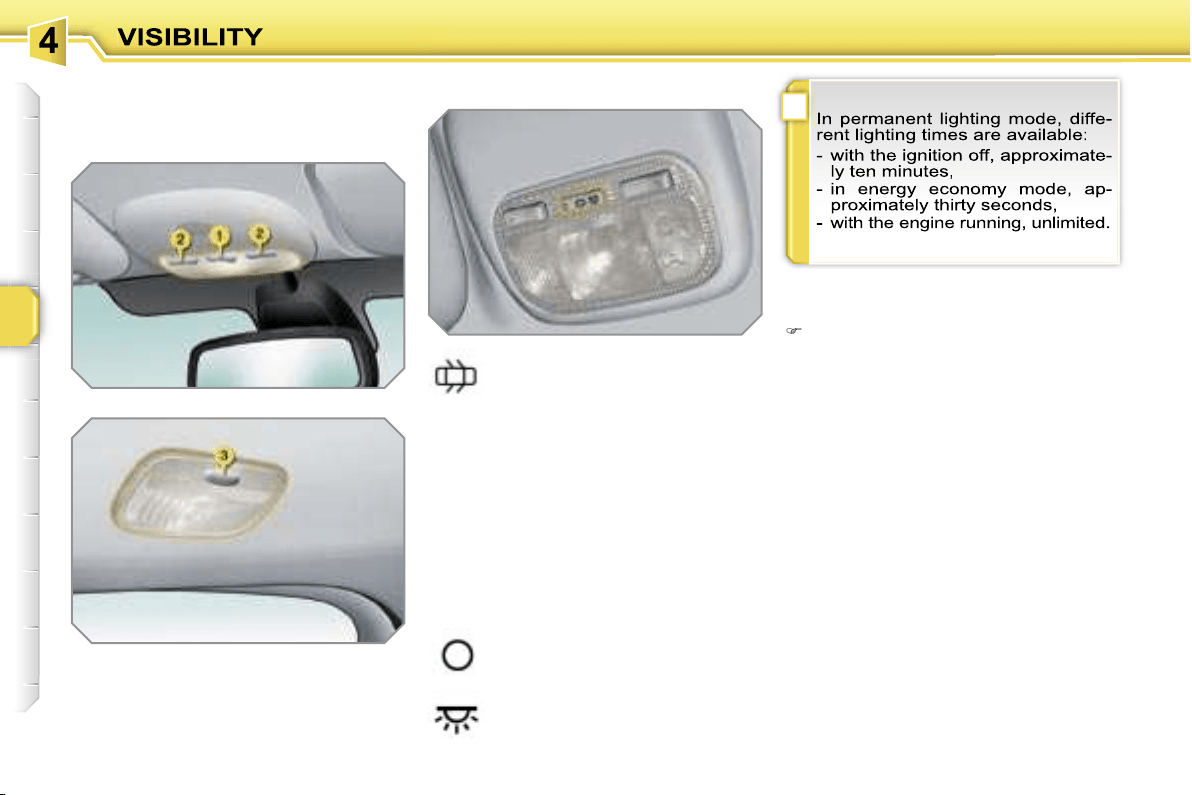
i
92
COURTESY LIGHTS
Selection and control of the various pas-
senger compartment lights.
1. Front courtesy light
2. Map reading lights
3. Rear courtesy light
Front and rear courtesy lights
In this position, the courtesy
light comes on gradually:
Map reading lights
With the ignition on, press the cor-
responding switch.
- when the vehicle is unlocked,
- when the key is removed from the ig-
nition,
- when the remote control locking but-
ton is activated, in order to locate your
vehicle.
It switches off gradually:
- when the vehicle is locked,
- when the ignition is switched on,
- 30 seconds after the last door is closed.
Permanently off.
Permanent lighting.
!
93
ADVICE ON CHILD
SEATS
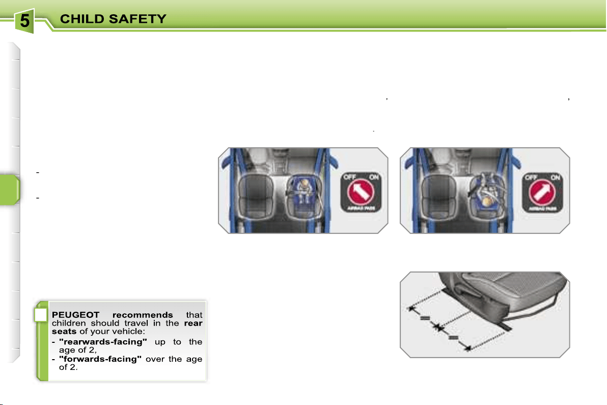
i
94
GENERAL POINTS RELATING
TO CHILD SEATS
Although one of PEUGEOT’s main cri-
teria when designing your vehicle, the
safety of your children also depends on
you.
For maximum safety, please follow
these precautions:
- in accordance with Directive 2003/20,
all children under the age of 12 or
less than one metre fifty tall must
travel in approved child seats suit-
ed to their weight
, on seats fitted with
a seat belt or ISOFIX mountings*,
-
statistically, the safest seats in
your vehicle for the transportation
of children are the rear seats,
-
a child weighing less than 9 kg
must travel in the "rearwards-fac-
ing" position both in the front and
in the rear.
INSTALLING A CHILD SEAT
USING A THREE POINT SEAT
BELT
"Forwards-facing"
When a "forwards-facing" child seat is
installed on the
front passenger seat
,
adjust the vehicle’s seat to the interme-
diate longitudinal position with the seat
back upright and leave the passenger
air bag armed**.
"Rearwards-facing"
When a "rearwards-facing" child seat is
installed on the
front passenger seat
,
it is essential that the passenger air
bag** is disarmed. Otherwise,
the child
would risk being seriously injured or
killed if the air bag were to inflate
.
Intermediate longitudinal
position
* The rules for transporting children are
specific to each country. Consult the
current legislation in your country.
** According to model.
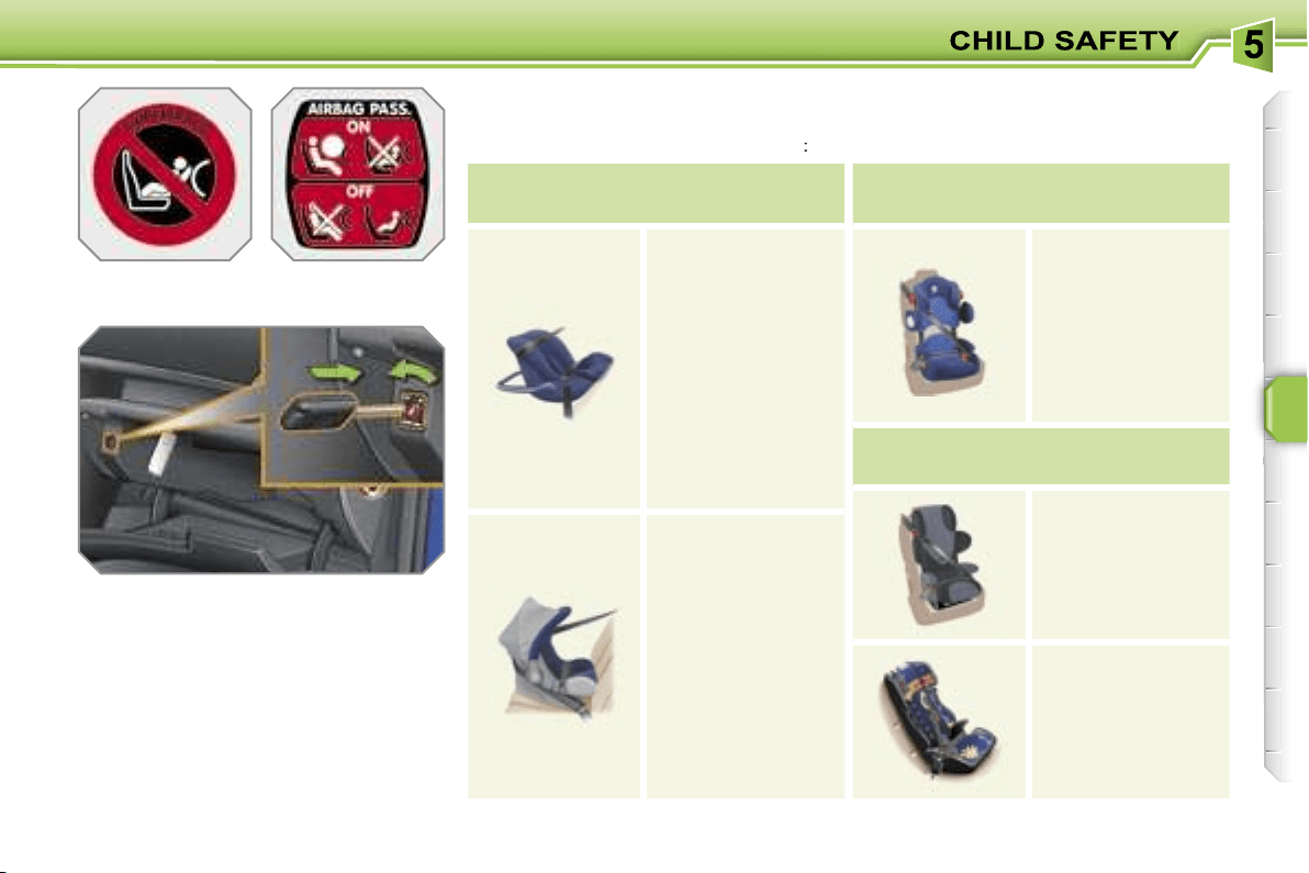
95
Passenger air bag OFF**
** According to version.
CHILD SEATS RECOMMENDED BY PEUGEOT
PEUGEOT offers a complete range of recommended child seats which are se-
cured using a
three point seat belt
:
Group 0: from birth to 10 kg
Group 0+: from birth to 13 kg
L1
"BRITAX
Babysure"
Installed in the
rear-facing position.
L2
"ROMER
Baby-Safe Plus"
Installed in the
rear-facing position.
Groups 1, 2 and 3: from 9 to 36 kg
L3
"KIDDY Life"
For the safety of
young children
(from 9 to 18 kg),
PEUGEOT
recommends use
of the
restraining
cushion.
Groups 2 and 3: from 15 to 36 kg
L4
"RECARO Start".
L5
"KLIPPAN Optima"
From the age
of 6 years
(approximately 22 kg),
the booster is
used on its own.
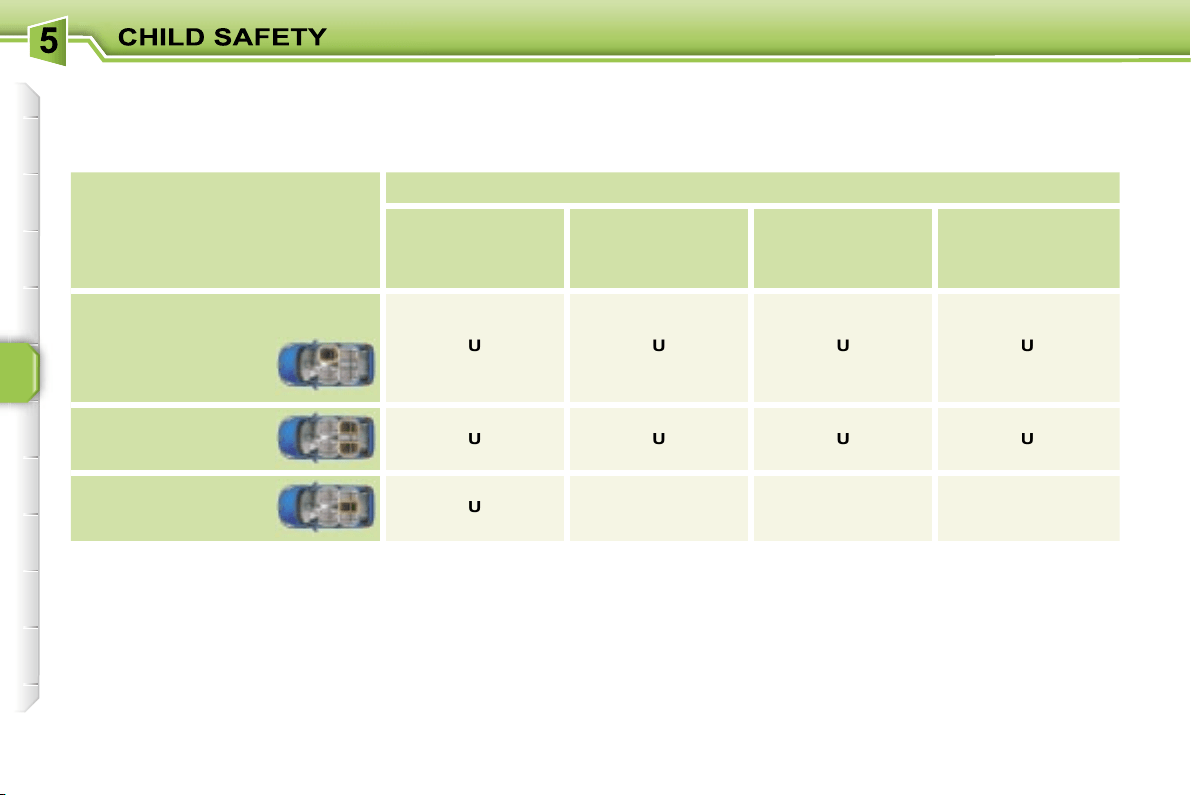
96
LOCATION OF CHILD SEATS SECURED USING THE SEAT BELT (SALOON)
In accordance with the European regulation (Directive 2000/3), this table indicates the options for the installation of child seats
secured using the seat belt and universally approved (a) in relation to the weight of the child and the seat in the vehicle.
* Except GTi.
(a) Universal child seat: child seat which can be installed in all vehicles using the seat belt.
(b) Group 0: from birth to 10 kg.
(c) Consult the legislation in force in your country before installing your child on this seat.
U:
seat suitable for the installation of a child seat secured using the seat belt and universally approved "rear facing" and/or
"forward facing".
X:
seat not suitable for the installation of a child seat of the weight group indicated.
Seat
Weight of the child/
indicative age
Less than 13 kg
(groups 0 (b)
and 0+)
Up to 1 year approx
From 9 to 18 kg
(group 1)
From 1 to 3 years
approx
From 15 to 25 kg
(group 2)
From 3 to 6 years
approx
From 22 to 36 kg
(group 3)
From 6 to 10 years
approx
Front passenger seat (c)
- fixed
U
U
U
U
- height adjustable
Rear side seats
U
U
U
U
Rear centre seat*
U
X
X
X
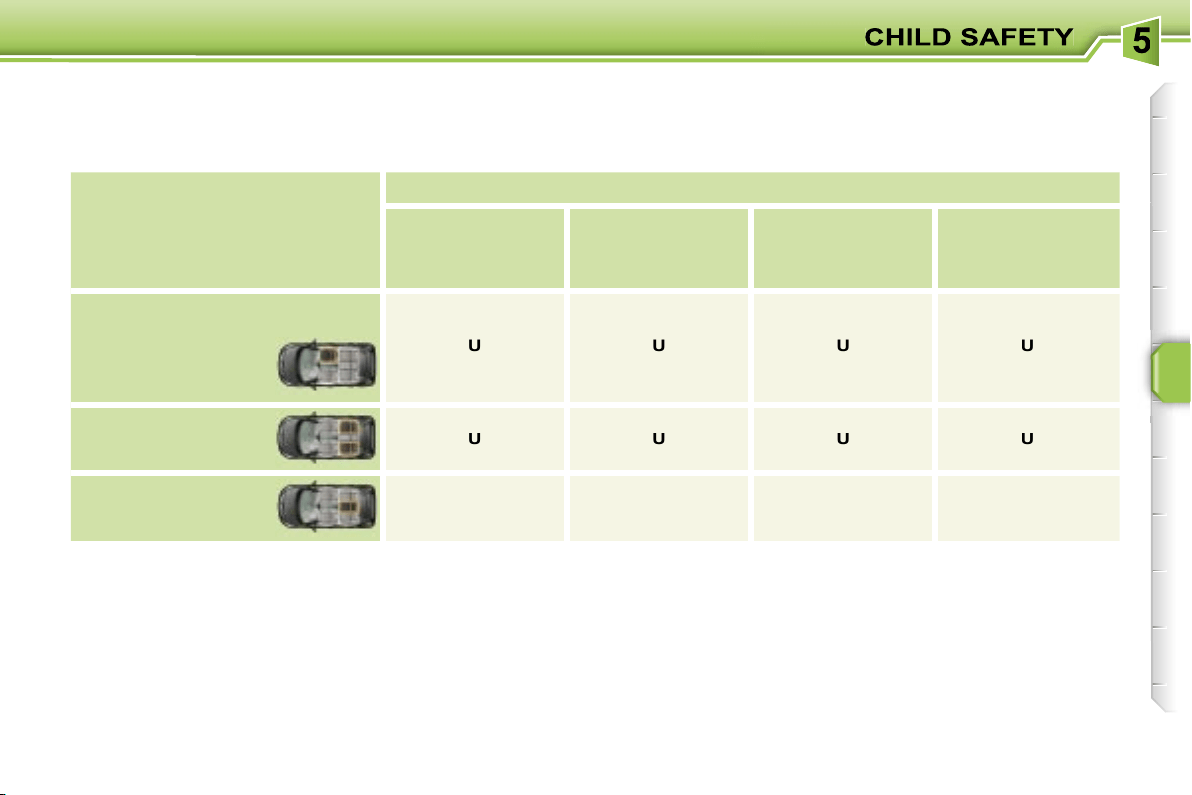
97
LOCATION OF CHILD SEATS SECURED USING THE SEAT BELT (SW)
In accordance with the European regulation (Directive 2000/3), this table indicates the options for the installation of child seats
secured using the seat belt and universally approved (a) in relation to the weight of the child and the seat in the vehicle.
* The rear left side seat becomes unusable.
(a) Universal child seat: child seat which can be installed in all vehicles using the seat belt.
(b) Group 0: from birth to 10 kg.
(c) Consult the legislation in force in your country before installing your child on this seat.
U:
Seat suitable for the installation of a child seat secured using the seat belt and universally approved "rear facing" and/or
"forward facing".
Seat
Weight of the child/
indicative age
Less than 13 kg
(groups 0 (b)
and 0+)
Up to 1 year approx
From 9 to 18 kg
(group 1)
From 1 to 3 years
approx
From 15 to 25 kg
(group 2)
From 3 to 6 years
approx
From 22 to 36 kg
(group 3)
From 6 to 10 years
approx
Front passenger seat (c)
- fixed
U
U
U
U
- height adjustable
Rear side seats
U
U
U
U
Rear centre seat
U*
U*
U*
U*
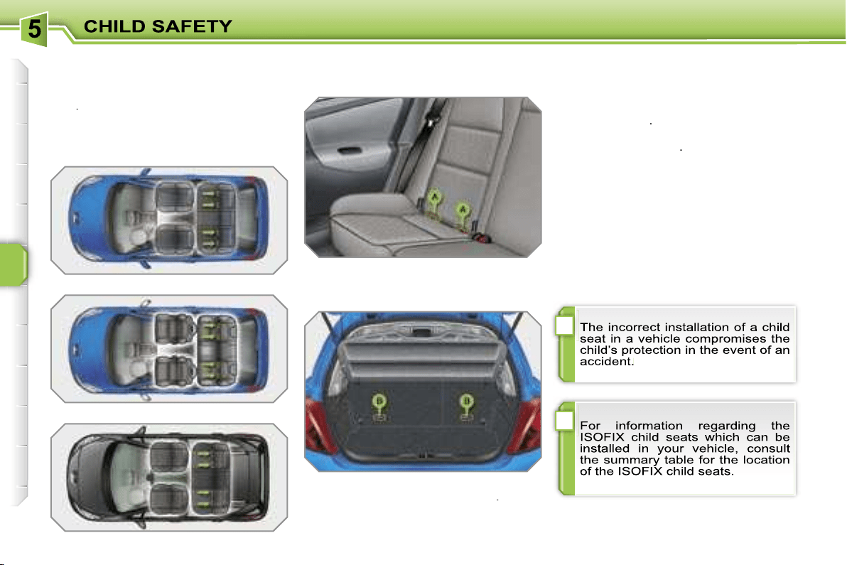
!
i
98
"ISOFIX" MOUNTINGS
Your vehicle has been approved in ac-
cordance with the
new ISOFIX regula-
tion
.
The seats*, represented below, are fit-
ted with regulation ISOFIX mountings:
These are three rings for each seat:
- two rings
A
, located between the ve-
hicle seat back and cushion, indicated
by a label,
- a ring
B
, for fixing the upper strap re-
ferred to as the
TOP TETHER
.
This ISOFIX mounting system guaran-
tees you fast, reliable and safe fitting of
the child seat in your vehicle.
The
ISOFIX child seats
are fitted with
two locks which are secured easily on
the two rings
A
.
Some also have an
upper strap
which
is attached to ring
B
.
To attach this strap, raise the vehicle
seat’s head restraint then pass the hook
between its rods. Then fix the hook on
ring
B
and tighten the upper strap.
* According to version.
Saloon
GTi
SW
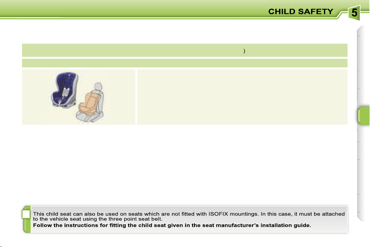
i
99
ISOFIX CHILD SEAT RECOMMENDED BY PEUGEOT AND APPROVED FOR YOUR VEHICLE
ISOFIX RÖMER Duo Plus
(size category
B1
)
Group 1: from 9 to 18 kg
Installed in the forward facing position.
Fitted with an upper strap to be secured on the ISOFIX upper ring,
referred to as the TOP TETHER.
Three seat body angles: sitting, reclining, lying.

100
SUMMARY TABLE FOR THE INSTALLATION OF ISOFIX CHILD SEATS (SALOON)
In accordance with the European regulation (ECE 16), this table indicates the options for the installation of ISOFIX child seats
on the vehicle seats fitted with ISOFIX mountings.
In the case of the universal and semi-universal ISOFIX child seats, the child seat’s ISOFIX size category, determined by a
letter from
A
to
G
, is indicated on the child seat next to the ISOFIX logo.
IUF:
seat suitable for the installation of an
I
sofix
U
niversal seat, "
F
orward facing" and secured using the "Top Tether" upper strap.
IL-SU:
seat suitable for the installation an
I
sofix
S
emi-
U
niversal seat which is:
- "rear facing" fitted with a "Top Tether" upper strap or a stay,
- "forward facing" fitted with a stay,
- an infant car seat fitted with a "Top Tether" upper strap or a stay.
For the securing of the "Top Tether" upper strap, refer to the "Isofix Mountings" section.
X:
seat which is not suitable for the installation of an ISOFIX seat of the size category indicated.
* The ISOFIX infant car seat, fixed to the lower rings of a seat equipped with ISOFIX mountings, occupies the three rear
seats.
To install it on the rear seats of a 3-door model, the front seat belt must be adjusted to the lowest position.
** The head restraint of the seat equipped with ISOFIX mountings must be removed and stored.
Weight of the child/
indicative age
Less than 10 kg
(group 0)
Up to 6 months
approx
Less than 10 kg
(group 0)
Less than 13 kg
(group 0+)
Up to 1 year approx
From 9 to 18 kg
(group 1)
From 1 to 3 years approx
Type of ISOFIX
child seat
Infant car seat*
"rear facing"
"rear facing"
"forward facing"
ISOFIX size category
F
G
C*
D**
E
C*
D**
A
B
B1
Universal and
semi-universal
ISOFIX child seats
which can be installed
on the rear seats
IL-SU**
X
IL-SU**
X
IL-SU**
IUF**
IL-SU**
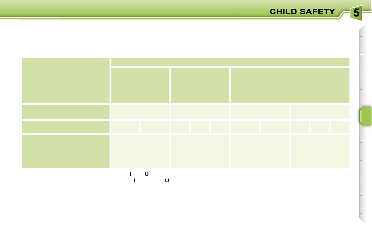
101
SUMMARY TABLE FOR THE INSTALLATION OF ISOFIX CHILD SEATS (GTi)
In accordance with the European regulation (ECE 16), this table indicates the options for the installation of ISOFIX child seats
on the vehicle seats fitted with ISOFIX mountings.
In the case of the universal and semi-universal ISOFIX child seats, the child seat’s ISOFIX size category, determined by a
letter from
A
to
G
, is indicated on the child seat next to the ISOFIX logo.
IUF:
seat suitable for the installation of an
I
sofix
U
niversal seat, "
F
orward facing" and secured using the "Top Tether" upper strap.
IL-SU:
seat suitable for the installation an
I
sofix
S
emi-
U
niversal seat which is:
- "rear facing" fitted with a "Top Tether" upper strap or a stay,
- "forward facing" fitted with a stay.
For the securing of the "Top Tether" upper strap, refer to the "Isofix Mountings" section.
X:
seat which is not suitable for the installation of an ISOFIX seat of the size category indicated.
* The corresponding front seat belt must be adjusted to the highest position minus one notch.
The corresponding front seat must be adjusted to the mid-way longitudinal position plus two notches.
** The corresponding front seat belt must be adjusted to the highest position minus one notch.
Weight of the child/
indicative age
Less than 10 kg
(group 0)
Up to 6 months
approx
Less than 10 kg
(group 0)
Less than 13 kg
(group 0+)
Up to 1 year approx
From 9 to 18 kg
(group 1)
From 1 to 3 years approx
Type of ISOFIX
child seat
Infant car seat
"rear facing"
"rear facing"
"forward facing"
ISOFIX size category
F
G
C*
D**
E
C*
D**
A
B
B1
Universal and semi-universal
ISOFIX child seats
which can be installed
on the rear seats
X
IL-SU
IL-SU
IUF
IL-SU
102
SUMMARY TABLE FOR THE INSTALLATION OF ISOFIX CHILD SEATS (SW)
In accordance with the European regulation (ECE 16), this table indicates the options for the installation of ISOFIX child seats
on the vehicle seats fitted with ISOFIX mountings.
In the case of the universal and semi-universal ISOFIX child seats, the child seat’s ISOFIX size category, determined by a
letter from
A
to
G
, is indicated on the child seat next to the ISOFIX logo.
IUF:
seat suitable for the installation of an
I
sofix
U
niversal seat, "
F
orward facing" and secured using the "Top Tether" upper strap.
IL-SU:
seat suitable for the installation an
I
sofix
S
emi-
U
niversal seat which is:
- "rear facing" fitted with a "Top Tether" upper strap or a stay,
- "forward facing" fitted with a stay,
- an infant car seat fitted with a "Top Tether" upper strap or a stay.
For the securing of the "Top Tether" upper strap, refer to the "Isofix Mountings" section.
X:
seat which is not suitable for the installation of an ISOFIX seat of the size category indicated.
* The ISOFIX infant car seat, fixed to the lower rings of a seat equipped with ISOFIX mountings, occupies the three rear
seats and prevents use of the 2/3 - 1/3 modularity.
** The front seat must be adjusted to the most forward position minus five notches.
(a) The head restraint of the seat equipped with ISOFIX mountings must be removed and stored.
Weight of the child/
indicative age
Less than 10 kg
(group 0)
Up to 6 months
approx
Less than 10 kg
(group 0)
Less than 13 kg
(group 0+)
Up to 1 year approx
From 9 to 18 kg
(group 1)
From 1 to 3 years approx
Type of ISOFIX child seat
Infant car seat*
"rear facing"
"rear facing"
"forward facing"
ISOFIX size category
F
G
C**
D
E
C**
D
A
B
B1
Universal and semi-universal
ISOFIX child seats
which can be installed on the
rear seats
IL-SU (a)
IL-SU (a)
IL-SU (a)
IUF (a)
IL-SU (a)
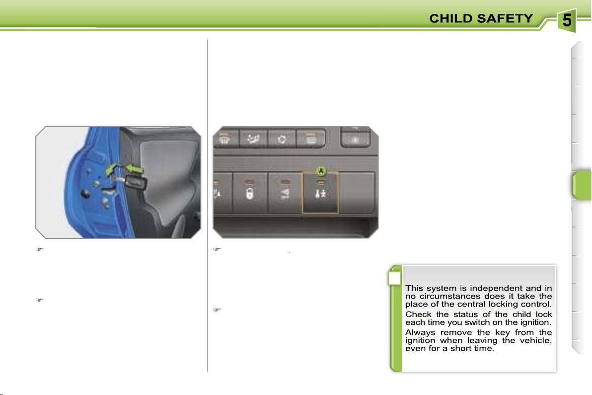
!
103
MANUAL CHILD
LOCK
Mechanical system to prevent opening
of the rear door using its interior control.
The control is located on the edge of
each rear door.
Turn the red control one quarter of
a turn to the right using the ignition
key.
ELECTRIC CHILD LOCK
Remote control system to prevent open-
ing of the rear doors using their interior
controls.
The control is located in the centre of
the fascia.
Press button
A
.
The indicator light on button
A
comes
on, accompanied by a message on the
multifunction display.
Locking
Unlocking
Turn the red control one quarter of a
turn to the left using the ignition key.
Activation
Deactivation
Press button
A
again.
The indicator light on button
A
switches
off, accompanied by a message on the
multifunction display.
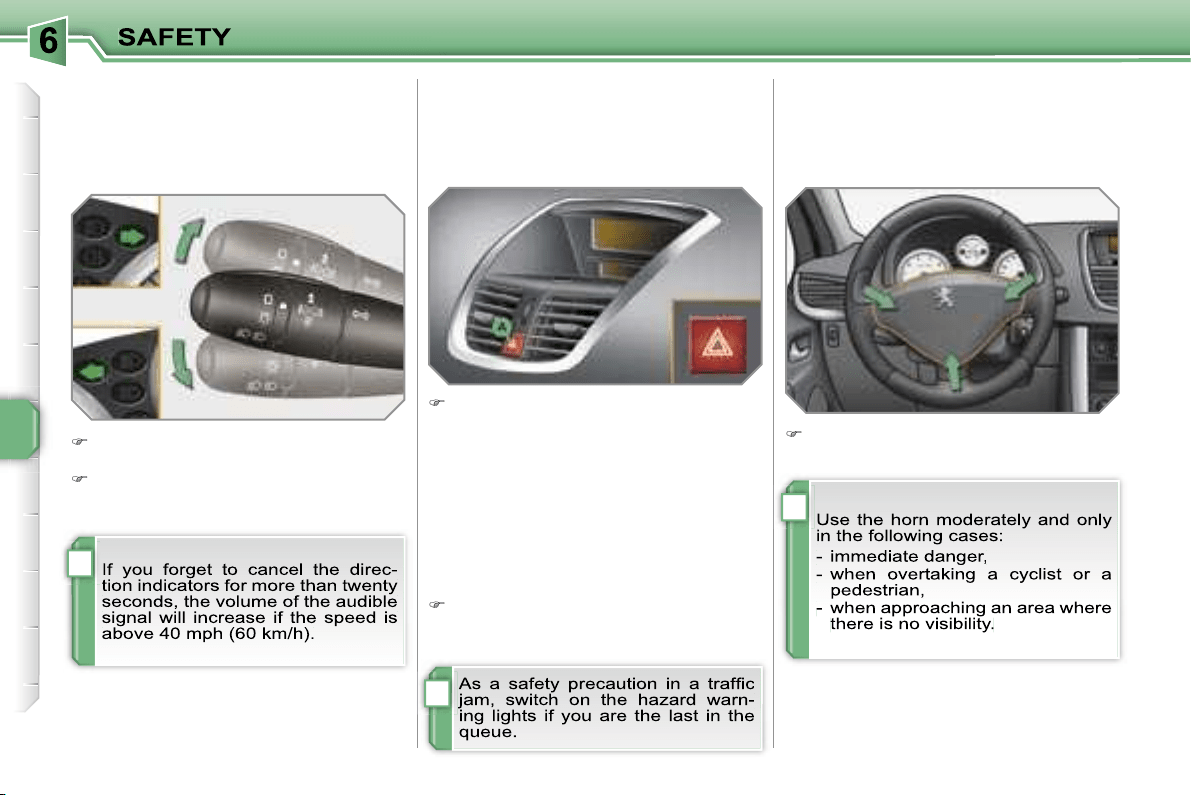
i
i
i
104
DIRECTION INDICATORS
Selection of the left or right direction
indicators to signal a change of direc-
tion of the vehicle.
Lower the lights stalk when moving
to the left.
Raise the lights stalk when moving
to the right.
HAZARD WARNING LIGHTS
A visual warning by means of the
direction indicators to alert other road
users to a vehicle breakdown, towing or
accident.
Press button
A
, the direction indica-
tors flash.
They can operate with the ignition off.
Automatic lighting of hazard
warning lights*
When braking in an emergency,
depending on the deceleration, the
hazard warning lights come on.
They will switch off automatically the
first time you accelerate.
If they do not, press button
A
to
switch the direction indicators off
HORN
Audible warning to alert other road
users to an imminent danger.
Press one of the spokes of the steer-
ing wheel.
* According to country.
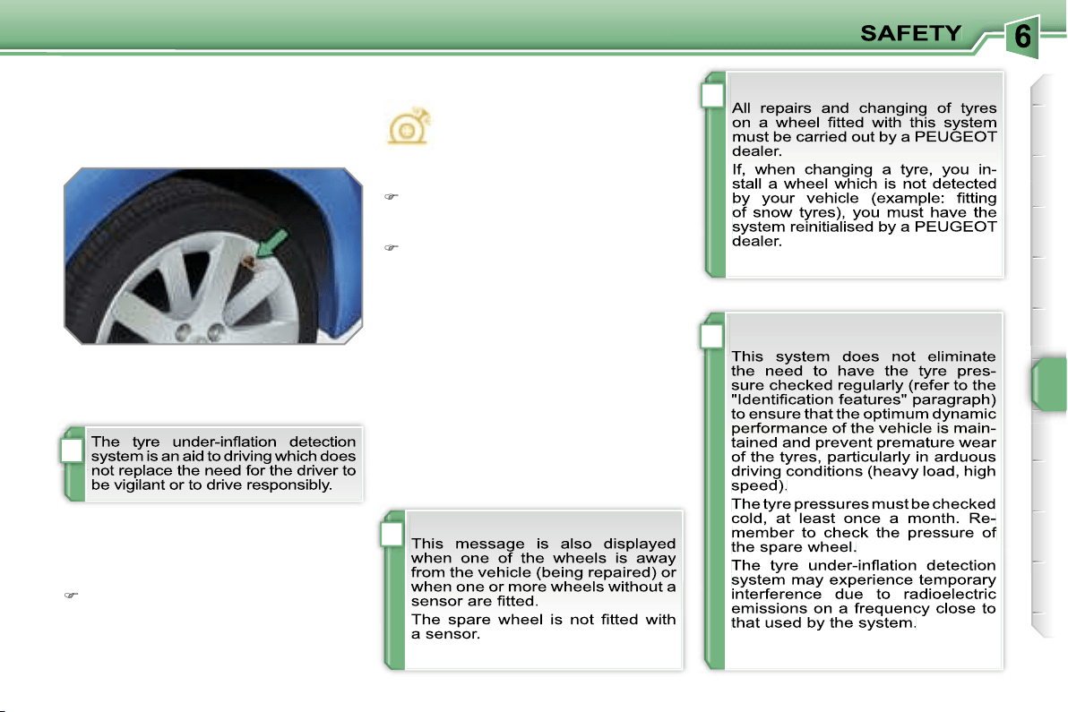
!
i
i
i
105
TYRE UNDER-INFLATION
DETECTION
System which automatically checks the
pressure of the tyres while driving.
Sensors fitted in each valve trigger a
warning in the event of malfunction
(speed above 12 mph (20 km/h)).
A message appears on the multifunc-
tion display, accompanied by an audible
signal, to locate the wheel concerned.
Check the tyre pressures as soon as
possible.
This check must be carried out when
the tyres are cold.
Flat tyre
This warning light and the
STOP
warning light come on on the
instrument panel, accompanied
by an audible signal and a mes-
sage on the multifunction display
locating the wheel concerned.
Stop immediately, avoiding any sud-
den movement of the steering wheel
and the brakes.
Change the damaged wheel (punc-
tured or very deflated tyre), and have
the tyre pressure checked as soon
as possible.
Puncture
Sensor(s) not detected or faulty
A message appears on the multifunc-
tion display, accompanied by an audi-
ble signal, to locate the wheel or wheels
which are not detected or to indicate a
fault in the system.
Contact a PEUGEOT dealer to replace
the faulty sensor(s).
!
i
106
BRAKING ASSISTANCE
SYSTEMS*
Group of supplementary systems which
help you to obtain optimum braking in
complete safety in emergency situations:
- the anti-lock braking system (ABS),
- the electronic brake force distribution
(EBFD),
- the emergency braking assistance
(EBA).
Anti-lock braking system
and electronic brake force
distribution
Linked systems which improve the
stability and manoeuvrability of your
vehicle when braking, in particular on
poor or slippery surfaces.
Operating fault
If this warning light comes on,
accompanied by an audible
signal and a message on the
multifunction display, it indi-
cates a malfunction of the anti-lock brak-
ing system which could result in loss of
control of the vehicle when braking.
If this warning light comes on,
together with the
STOP
and
ABS warning lights, accompa-
nied by an audible signal and a
message on the multifunction display, it
indicates a malfunction of the electron-
ic brake force distribution which could
result in loss of control of the vehicle
when braking.
You MUST stop as soon as it is safe
to do so.
In both cases, contact a PEUGEOT
dealer.
Emergency braking assistance
System which, in an emergency, ena-
bles you to obtain the optimum braking
pressure more quickly, thus reducing
the stopping distance.
* According to country.
Activation
The anti-lock braking system comes
into operation automatically when there
is a risk of wheel lock.
Normal operation of the ABS may make
itself felt by slight vibration of the brake
pedal.
Activation
It is triggered by the speed at which the
brake pedal is pressed.
The effect of this is a reduction in the
resistance of the pedal and an increase
in braking efficiency.
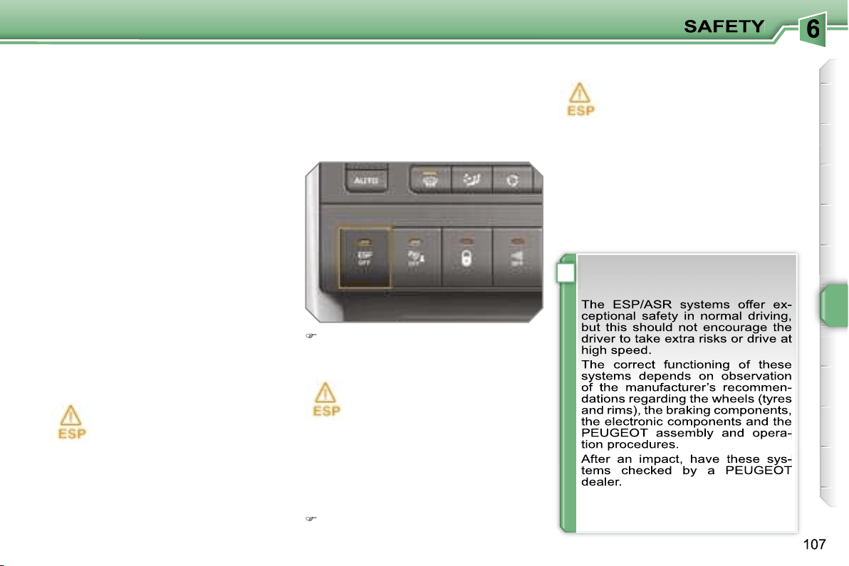
!
Disarming
In exceptional conditions (starting a
vehicle which is bogged down, stuck
in snow, on soft ground, ...), it may be
advisable to disarm the ASR and ESP
systems, so that the wheels can move
freely and regain grip.
Press the
"ESP OFF"
button, locat-
ed in the centre of the fascia.
If this warning light comes on on the instru-
ment panel and the indicator light on the
button comes on, this indicates that the
ASR and ESP systems are disarmed.
Reactivation
These systems are reactivated automat-
ically each time the ignition is switched
back on or from 30 mph (50 km/h) (ex-
cept in the case of the 1.6 l 16V THP
175 bhp petrol engine).
Press the
"ESP OFF"
button again
to reactivate them manually.
Operating fault
If this warning light comes on,
accompanied by an audible sig-
nal and a message on the mul-
tifunction display, this indicates
a malfunction of these systems.
Contact a PEUGEOT dealer to have the
systems checked.
TRAJECTORY CONTROL
SYSTEMS
Associated systems which guarantee
the directional stability of the vehicle
within the limits of the laws of physics:
- the anti-skid regulation (ASR),
- the electronic stability programme
(ESP).
Activation
These systems are activated auto-
matically each time the vehicle is started.
Anti-skid regulation and
electronic stability programme
The anti-skid regulation optimises trac-
tion to prevent skidding of the wheels,
by acting on the brakes of the driving
wheels and on the engine.
The electronic stability programme acts
on the brake of one or more wheels and
on the engine to keep the vehicle on the
trajectory required by the driver.
They come into operation in
the event of a grip or trajectory
problem.
This is indicated by flashing of
this warning light on the instru-
ment panel.
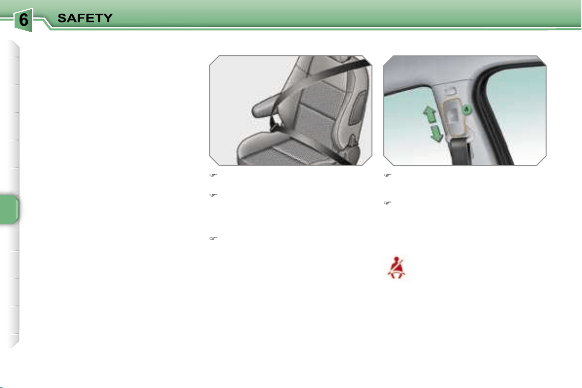
108
SEAT BELTS
Front seat belts
The front seat belts are fitted with a pre-
tensioning and force limiting system.
This system improves safety in the front
seats in the event of front impacts. De-
pending on the severity of the impact,
the pretensioning system instantly tight-
ens the seat belts against the body of
the occupants.
The pretensioning seat belts are active
when the ignition is on.
The force limiter reduces the pressure
of the seat belt on the chest of the oc-
cupant, increasing his protection.
On the 5-door and GTi versions, a slid-
er, fitted on the seat belt, makes it pos-
sible to support the buckle as close as
possible to the strap return.
Height adjustment
Seat belt not fastened/unfastened
warning light
Fastening
Pull the strap, then insert the tongue
in the buckle.
Check that the seat belt is fastened
correctly by pulling the strap.
To lower the attachment point,
squeeze control
A
and slide it down-
wards.
To raise the attachment point, slide
control
A
upwards.
When the ignition is switched on,
this warning light comes on on
the instrument panel if the driver*
and/or the front passenger has
not fastened his seat belt.
Above approximately 12 mph (20 km/h)
and for two minutes, this warning light
flashes accompanied by an audible sig-
nal of increasing volume. When the two
minutes have elapsed, this warning light
remains on until the driver* and/or the
front passenger fastens his seat belt.
* According to country.
Unfastening
Press the red button on the buckle.
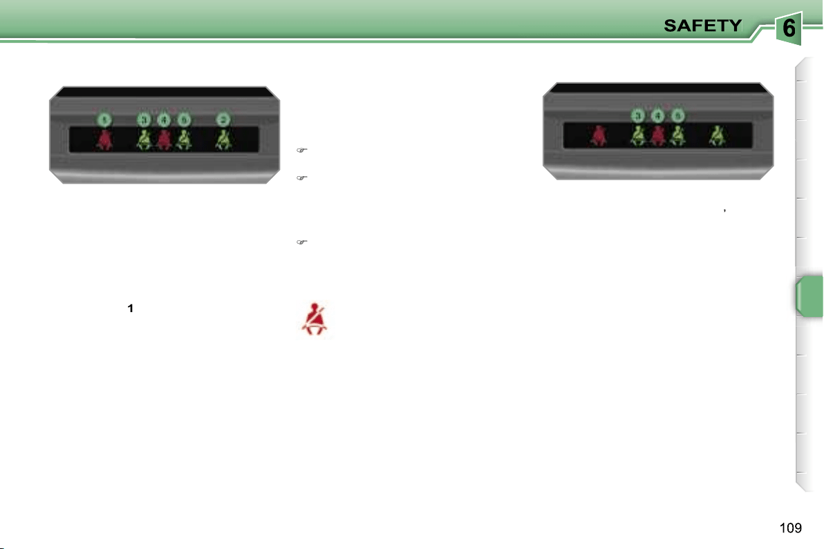
1.
Front left seat belt warning light.
2.
Front right seat belt warning light.
3.
Rear left seat belt warning light.
4.
Rear centre seat belt warning
light**.
5.
Rear right seat belt warning light.
On the central bar, the corresponding
warning light
1
or
2
comes on:
- in red, if the seat belt is not fastened
or is unfastened,
- in green, if it is fastened.
Seat belt not fastened/unfastened
warning lights bar
Rear seat belts
The rear seats are fitted with three seat
belts**, each with three anchoring points
and an inertia reel with force limiter.
Seat belt unfastened warning light
This warning light comes on on
the instrument panel if one or
more rear passengers unbuckle
their seat belt.
Fastening
Pull the strap, then insert the tongue
in the buckle.
Check that the seat belt is fastened
correctly by pulling the strap.
Seat belt unfastened warning
lights bar
When the ignition is switched on, the
corresponding warning lights
3
,
4**
and
5
come on for approximately 30 se-
conds:
- in red, if the seat belt is not fastened,
- in green, if it is fastened.
When the engine is running, the corre-
sponding warning light
3
,
4**
or
5
comes
on in red, accompanied by an audible
signal and a message on the multifunc-
tion display, if a rear passenger has un-
fastened his seat belt.
Unfastening
Press the red button on the buckle.
** Except GTi.
i
110
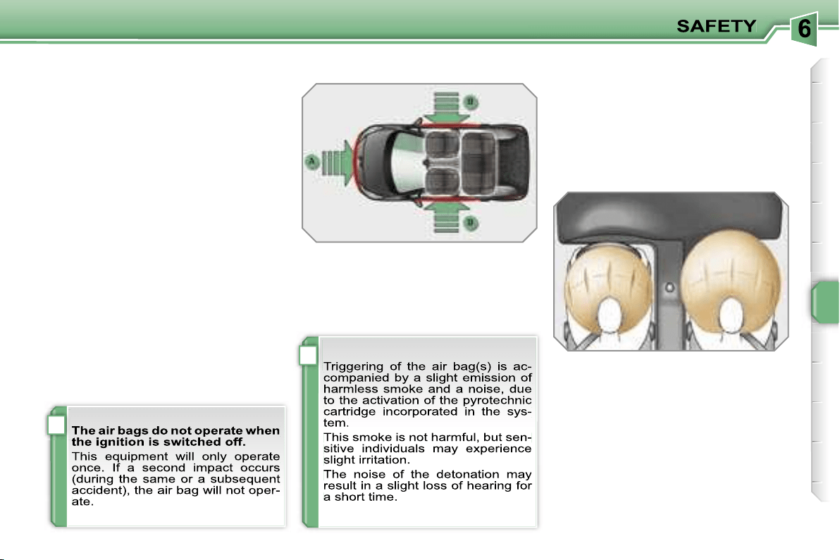
!
i
111
AIR BAGS
System designed to maximise the safety
of the occupants (with the exception of
the rear centre passenger) in the event
of violent collisions. It supplements the
action of the force-limiting seat belts.
If a collision occurs, the electronic de-
tectors record and analyse the front and
side impacts sustained in the impact
detection zones:
- in the case of a serious impact, the air
bags are triggered instantly and pro-
tect the occupants of the vehicle (with
the exception of the rear centre pas-
senger); immediately after the impact,
the air bags deflate rapidly so that
they do not hinder visibility or the exit
of the occupants,
- in the case of a minor or rear impact
or in certain roll-over conditions, the
air bags will not be triggered; the seat
belt alone is sufficient to provide opti-
mum protection in these situations.
Front air bags
System which protects the driver and
front passenger in the event of a seri-
ous front impact in order to limit the risk
of injury to the head and chest.
The driver’s air bag is incorporated in
the centre of the steering wheel; the
front passenger’s air bag is incorporat-
ed in the fascia above the glove box.
Activation
The air bags are triggered simultane-
ously, unless the passenger’s front air
bag is disarmed, in the event of a seri-
ous front impact applied to all or part of
the front impact zone
A
, in the longitu-
dinal centreline of the vehicle on a hori-
zontal plane and directed from the front
to the rear of the vehicle.
The front air bag inflates between the
front occupant of the vehicle and the
fascia to cushion his forward move-
ment.
Impact detection zones
A.
Front impact zone.
B.
Side impact zone.
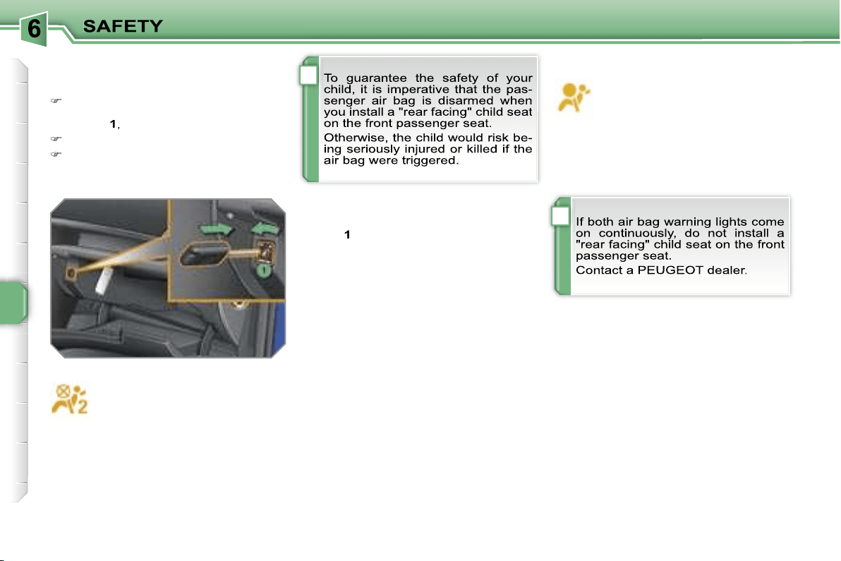
!
!
112
Operating fault
If this warning light comes on on
the instrument panel, accompa-
nied by an audible warning and
a message on the multifunction
display, contact a PEUGEOT dealer to
have the system checked. The air bags
may no longer be triggered in the event
of a serious impact.
According to version, this warn-
ing light comes on either on
the instrument panel or on the
central bar when the ignition is
on and until the air bag is re-
armed.
Reactivation
When you remove the child seat, turn
switch
1
to the
"ON"
position to re-arm
the air bag and so guarantee the safety
of your front passenger in the event of
an impact.
Deactivation
Only the front passenger’s air bag can
be disarmed:
with the ignition off,
insert the key
in the passenger air bag disarming
switch
1
,
turn it to the
"OFF"
position,
then, remove the key keeping the
switch in this position.
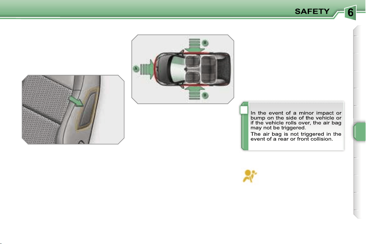
!
113
Side air bags*
System which protects the driver and
front passenger in the event of a seri-
ous side impact in order to limit the risk
of injury to the chest.
Each side air bag is incorporated in the
front seat back frame, on the door side.
Activation
It is triggered unilaterally in the event
of a serious side impact applied to all
or part of the side impact zone
B
, per-
pendicular to the longitudinal centreline
of the vehicle on a horizontal plane and
directed from the outside towards the
inside of the vehicle.
The side air bag inflates between the
front occupant of the vehicle and the
corresponding door trim pad.
Curtain air bags*
System which protects the driver and
passengers (with the exception of the
rear centre passenger) in the event of a
serious side impact in order to limit the
risk of head injuries.
Each curtain air bag is incorporated in
the pillars and the upper part of the pas-
senger compartment.
If this warning light comes on on
the instrument panel, accompa-
nied by an audible signal and a
message on the multifunction
display, contact a PEUGEOT dealer to
have the system checked. The air bags
may no longer be triggered in the event
of a serious impact.
* According to country.
Operating fault
Activation
It is triggered at the same time as the
corresponding side air bag in the event
of a serious side impact applied to all
or part of the side impact zone
B
, per-
pendicular to the longitudinal centreline
of the vehicle on a horizontal plane and
directed from the outside towards the
inside of the vehicle.
The curtain air bag inflates between the
front or rear occupant of the vehicle and
the windows.
Impact detection zones
A.
Front impact zone.
B.
Side impact zone.
!
114
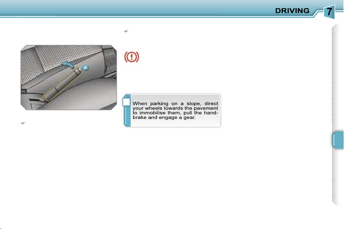
!
115
HANDBRAKE
Mechanical brake to hold the vehicle
when stationary.
Applying
Pull the handbrake to immobilise
your vehicle.
When the vehicle is being driv-
en, if this warning light and the
STOP
warning light come on,
accompanied by an audible sig-
nal and a message on the multi-function
display, this indicates that the hand-
brake is still on or has not been properly
released.
Releasing
Pull on the handle and press the
button
A
to release the handbrake.
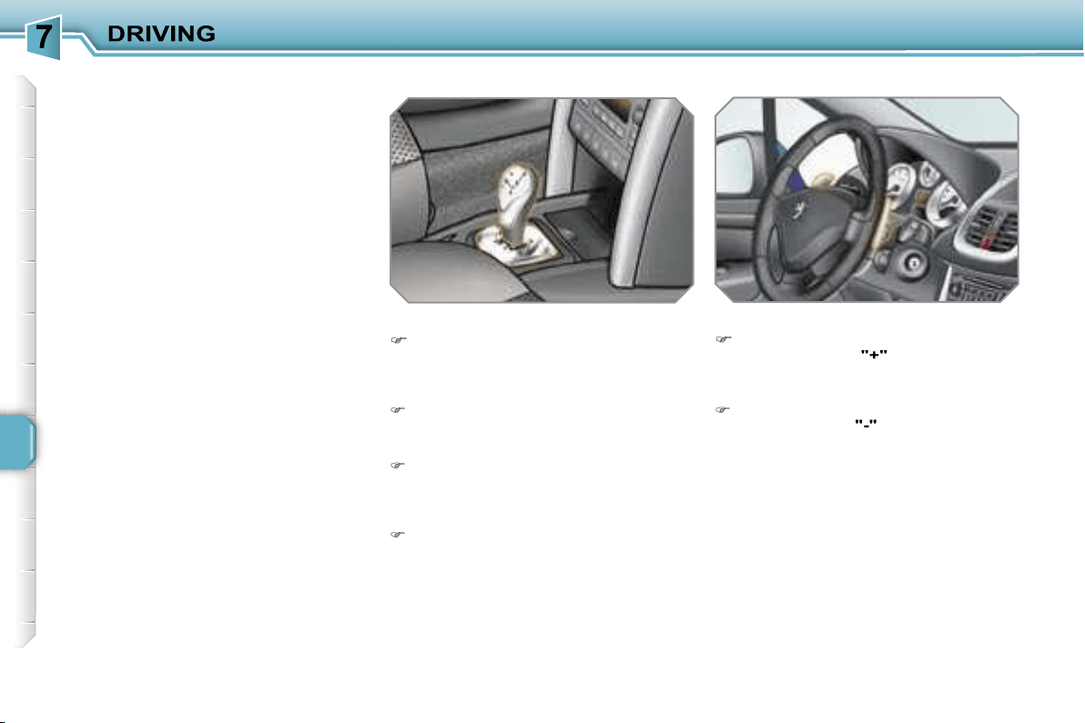
116
"2 TRONIC" GEARBOX
(SALOON)*
Five-speed controlled manual gearbox
which offers a choice between the com-
fort of automatic operation or the pleas-
ure of manual gear changing.
Three driving modes are offered:
- the
automated
mode for automatic
control of the gears by the gearbox,
- the
sequential
mode for manual
changing of the gears by the driver,
- the
auto sequential
mode for over-
taking, for example, remaining in the
automated mode while using the func-
tions of the sequential mode.
Gear lever
R.
Reverse
With your foot on the brake, move
the lever upwards to select this po-
sition.
N.
Neutral.
With your foot on the brake, select
this position to start the engine.
A.
Automated mode.
Move the lever downwards to se-
lect this mode.
M +/-
Sequential mode with manual
gear changing.
Move the lever downwards, then to
the left to select this mode, then:
- push forwards to change up a gear,
- or push rearwards to change down a
gear.
Steering wheel controls
+.
Change up control.
Press the back of the steering
wheel control
"+"
to change up a
gear.
-.
Change down control.
Press the back of the steering
wheel control
"-"
to change down a
gear.
* During the course of the year.
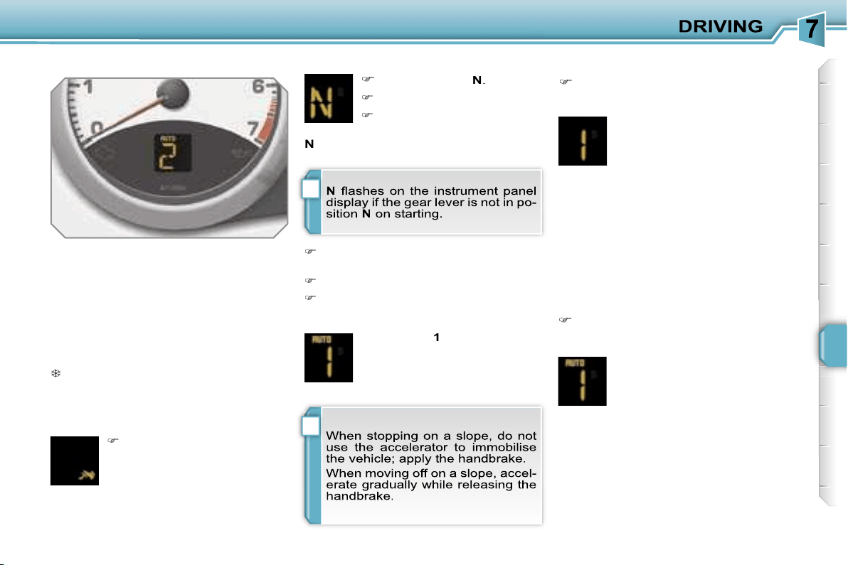
i
i
117
Instrument panel displays
Gear lever positions
Moving off
Sequential mode
After starting the vehicle, select po-
sition
M
to change to sequential
mode.
N
Neutral
R
Reverse
1, 2, 3, 4, 5
Gears in sequential mode
AUTO.
This comes on when the
automated mode is selected.
It switches off on changing to
sequential mode.
In the automated mode, if the
gearbox detects poor grip, this
warning light comes on.
Place your
foot on the
brake
when this warning light
is displayed (e.g.: starting the
engine).
Select position
N
.
Press the brake pedal.
Start the engine.
N
appears on the instrument panel dis-
play.
Select first gear (position
M
or
A
) or
reverse (position
R
).
Release the handbrake.
Take your foot off the brake pedal,
then accelerate.
AUTO
and
1
or
R
appear on
the instrument panel display.
AUTO
disappears and the
gears engaged appear in suc-
cession on the instrument
panel display.
The gear change requests are only car-
ried out if the engine speed permits.
When driving at low speed, on ap-
proaching a stop sign or traffic lights for
example, the gearbox changes down to
first gear automatically.
The gearbox then operates in auto-
adaptive mode, without any action on
the part of the driver. It continuously se-
lects the most suitable gear in relation
to the following parameters:
- driving style,
- road conditions,
- vehicle load.
AUTO
and the gear engaged
appear on the instrument pan-
el display.
Automated mode
Following use of the sequential
mode, select position
A
to return to
the automated mode.
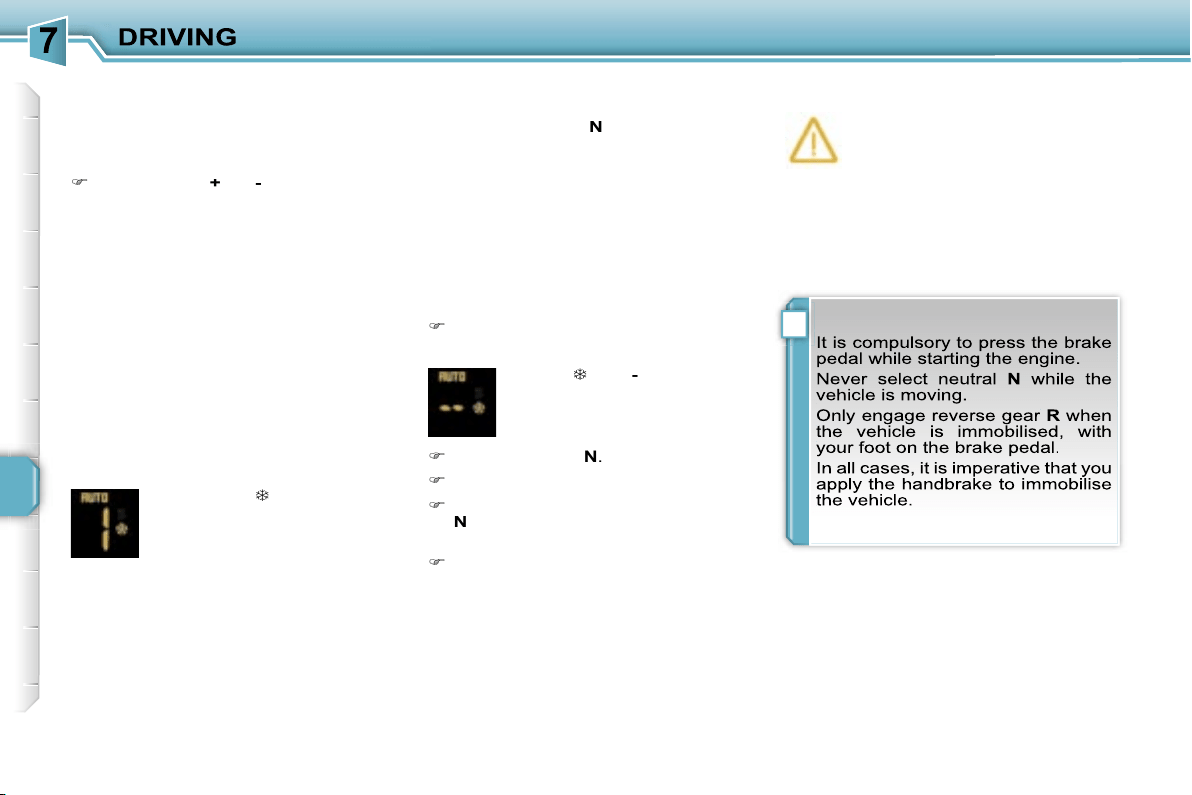
!
118
"Auto sequential" mode
This mode enables you to overtake, for
example, while remaining in the auto-
mated mode, using the functions of the
sequential mode.
Operate the
+
or
-
positions of the
steering wheel controls.
The gearbox engages the required gear if
the engine speed permits.
AUTO
remains
displayed on the instrument panel.
After a few minutes without any action
on the controls, the gearbox resumes
automatic control of the gears.
Stopping the vehicle
Before switching off the engine, you can
change to position
N
to be in neutral.
In this case, it is imperative that you
apply the handbrake to immobilise the
vehicle.
Operating fault
With the ignition on, if this warn-
ing light comes on and
AUTO
flashes, accompanied by an au-
dible signal and a message on
the multifunction display, this indicates
a gearbox malfunction.
Contact a PEUGEOT dealer without
delay.
AUTO
and
appear on the
instrument panel display.
"Snow" automated mode
In the automated mode, if the vehi-
cle detects poor grip, the gearbox will
change automatically to the snow auto-
mated mode.
Reinitialisation
Following disconnection of the battery,
the gearbox must be reinitialised.
Switch on the ignition.
AUTO,
and
-
appear on the
instrument panel display.
Select position
N
.
Press the brake pedal.
Wait approximately 30 seconds until
N
or a gear appears on the instru-
ment panel display.
Release the brake pedal.
The gearbox is operational again.

119
"PORSCHE TIPTRONIC
SYSTEM" AUTOMATIC
GEARBOX
Four-speed automatic gearbox which
offers a choice between the comfort of
fully automatic operation, enhanced by
sport and snow programmes, or manual
gear changing.
Therefore, four driving modes are of-
fered:
-
automatic
operation for electronic
management of the gears by the gear-
box,
-
sport
programme for a more dynamic
style of driving,
-
snow
programme to improve driving
when traction is poor,
-
manual
operation for sequential
changing of the gears by the driver.
Gear lever
P.
Park.
- Immobilisation of the vehicle,
handbrake on or off.
- Starting the engine.
R.
Reverse.
- Reversing manoeuvres, vehicle
stationary, engine at idle.
N.
Neutral.
- Immobilisation of the vehicle,
handbrake on.
- Starting the engine.
D.
Automatic operation.
M. +/-
Manual operation with sequen-
tial changing of the four gears.
Press forwards to change up through
the gears.
or
Press rearwards to change down
through the gears.
Displays on the instrument panel
When you move the lever in the gate
to select a position, the corresponding
indicator light is displayed on the instru-
ment panel.
P.
Park
R.
Reverse
N.
Neutral
D.
Drive (Automatic driving)
S.
Sport
programme
.
Snow
programme
1, 2, 3, 4.
Gear engaged during manual
operation
-.
Invalid value during manual opera-
tion
Press the brake pedal when
this indicator light is dis-
played on the instrument
panel (e.g.: starting the en-
gine).
Gear selection gate
1.
Gear lever.
2.
Button
"S"
(sport)
.
3.
Button
"
"
(snow)
.
Foot on brake
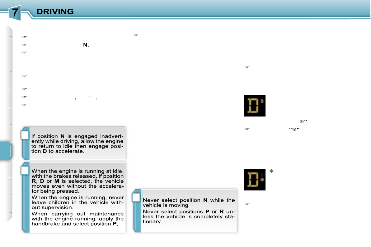
!
!
i
120
Moving off
Apply the handbrake.
Select position
P
or
N
.
Start the engine.
If this procedure is not followed, an au-
dible signal is heard, accompanied by a
message on the multifunction display.
With the engine running, press the
brake pedal.
Release the handbrake.
Select position
R
,
D
or
M
or
or
,
Gradually release the brake pedal.
The vehicle moves off immediately.
The gearbox then operates in auto-
adaptive mode, without any intervention
on the part of the driver. It continuously
selects the most suitable gear accord-
ing to the style of driving, the profile of
the road and the load in the vehicle.
For maximum acceleration without
touching the lever, press the accelera-
tor pedal down fully (kick down). The
gearbox changes down automatically
or maintains the gear selected until the
maximum engine speed is reached.
On braking, the gearbox changes down
automatically to provide efficient engine
braking.
If you release the accelerator sharply,
the gearbox will not change to a higher
gear for safety reasons.
Automatic operation
Select position
D
for
automatic
changing of the four gears.
appears on the instrument
panel.
Snow programme "
"
Press button
"
"
, after starting the
engine.
The gearbox adapts to driving on slip-
pery roads.
This programme improves starting and
drive when traction is poor.
S
appears on the instrument
panel.
Sport programme "S"
Press button
"S"
, after starting the
engine.
The gearbox automatically favours a
dynamic style of driving.
Sport and snow programmes
These two special programmes supple-
ment the automatic operation in very
specific conditions of use.
Return to automatic operation
At any time, press the button se-
lected again to quit the programme
engaged and return to auto-adaptive
mode.
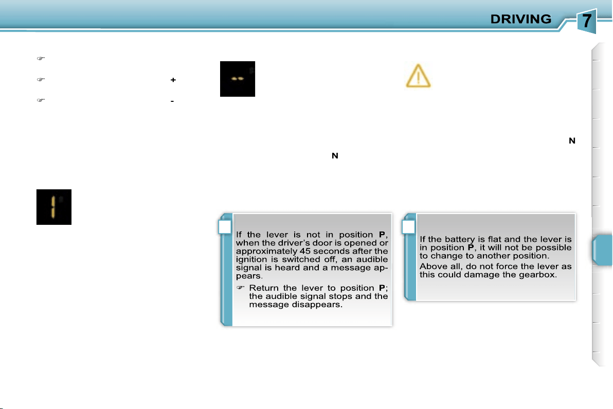
!i
121
Stopping the vehicle
Before switching off the engine, you
can engage position
P
or
N
to place the
gearbox in neutral.
In both cases, apply the handbrake to
immobilise the vehicle.
Operating fault
When the ignition is on, the
lighting of this warning light, ac-
companied by an audible signal
and a message on the multi-
function display, indicates a gearbox
malfunction.
In this case, the gearbox switches to
emergency mode and is locked in 3rd
gear. You may feel a substantial knock
when changing from
P
to
R
and from
N
to
R
. This will not cause any damage to
the gearbox.
Do not exceed 60 mph (100 km/h), local
speed restrictions permitting.
Contact a PEUGEOT dealer as soon as
possible.
Manual operation
Select position
M
for
sequential
changing of the four gears.
Push the lever towards the
+
sign to
change up a gear.
Pull the lever towards the
-
sign to
change down a gear.
D
disappears and the gears
engaged appear in succes-
sion on the instrument panel.
In the event of under-revving
or over-revving, the gear se-
lected flashes for a few seconds, then
the actual gear engaged is displayed.
It is possible to change from position
D
(automatic) to position
M
(manual) at
any time.
When the vehicle is stationary or mov-
ing very slowly, the gearbox selects
gear
M1
automatically.
The sport and snow programmes do not
operate in manual mode.
It is only possible to change from one
gear to another if the vehicle speed and
engine speed permit; otherwise, the
gearbox will operate temporarily in au-
tomatic mode.
Invalid value during manual
operation
This symbol is displayed if a
gear is not engaged correctly
(selector between two posi-
tions).

i
122
SPEED LIMITER
System which prevents the vehicle from
exceeding the speed programmed by
the driver.
When the programmed speed limit is
reached, pressing the accelerator pedal
no longer has any effect.
The speed limiter is
switched on
man-
ually: it requires a programmed speed
of at least 20 mph (30 km/h).
The speed limiter is
switched off
by
switched off
switched off
manual operation of the control.
The programmed speed can be ex-
ceeded temporarily by pressing the ac-
celerator firmly.
To return to the programmed speed,
simply slow down to a speed below the
programmed speed.
The programmed speed remains in the
memory when the ignition is switched
off.
The controls of this system are grouped
together on stalk
A
.
1.
Speed limiter mode selection dial
2.
Value decrease button
3.
Value increase button
4.
Speed limiter on/off button
The programmed information is grouped
together on the instrument panel display.
5.
Speed limiter on/off indication
6.
Speed limiter mode selection indi-
cation
7.
Programmed speed value
Steering wheel controls
Displays on the instrument panel
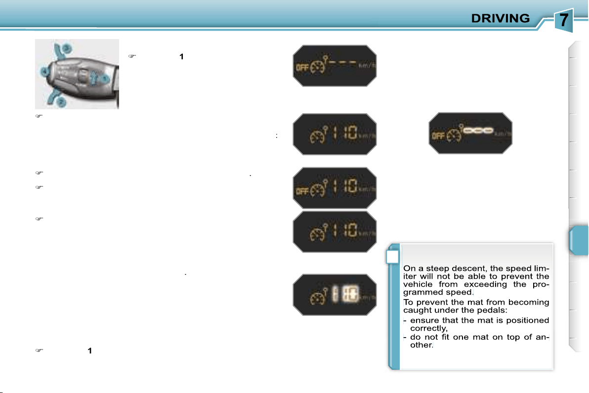
!
123
Programming
Turn dial
1
to the
"LIMIT"
position:
the speed limiter mode is selected
but is not switched on (OFF).
Exceeding the programmed speed
Pressing the accelerator pedal to exceed the programmed
speed will not have any effect unless you press the pedal
firmly
past the
point of resistance
.
The speed limiter is deactivated temporarily and the pro-
grammed speed, which is still displayed, flashes.
Returning to the programmed speed, by means of intention-
al or unintentional deceleration of the vehicle, automatically
cancels the flashing of the programmed speed.
Return to normal driving
Turn dial
1
to the
"0"
position: the speed limiter mode is
deselected. The display returns to the distance recorder.
Operating fault
In the event of a speed limiter mal-
function, the speed is cleared result-
ing in flashing of the dashes. Contact a
PEUGEOT dealer to have the system
checked.
You do not have to switch the speed
limiter on in order to set the speed.
Switch the speed limiter off by pressing button
4
: the dis-
play confirms that it has been switched off (OFF).
Switch the speed limiter back on by pressing button
4
again.
Set the speed value by pressing button
2
or
3
(e.g.:
70 mph (110 km/h)).
You can then change the programmed speed using buttons
2
and
3
:
- by + or - 1 mph (km/h) = short press,
- by + or - 5 mph (km/h) = long press,
- in steps of + or - 5 mph (km/h) = maintained press.
Switch the speed limiter on by pressing button
4
.
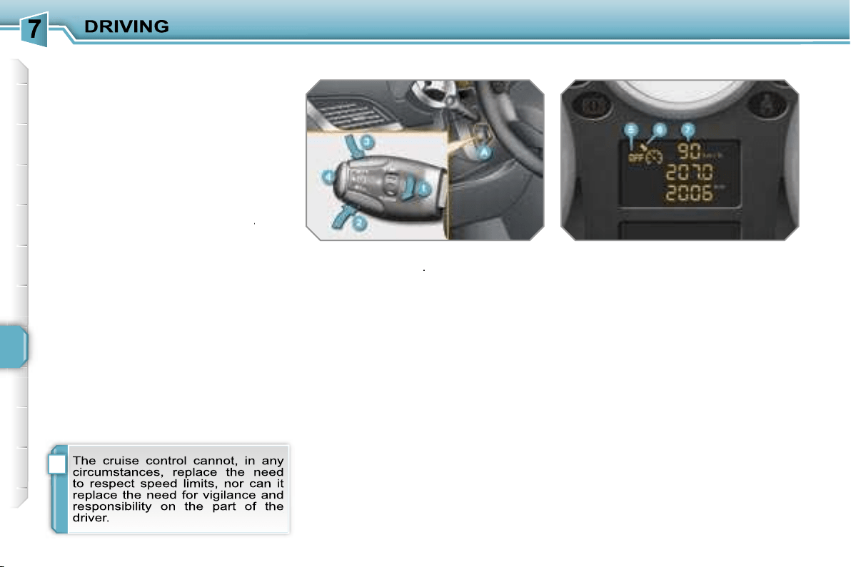
i
124
CRUISE CONTROL
System which automatically maintains
the speed of the vehicle at the value
programmed by the driver, without any
action on the accelerator pedal.
The cruise control is
switched on
manually: it requires a minimum vehi-
cle speed of 25 mph (40 km/h) and the
engaging of fourth gear on the manual
gearbox.
The cruise control is
switched off
man-
switched off
switched off
ually or by pressing the brake or clutch
pedal or on triggering of the ESP sys-
tem.
It is possible to exceed the programmed
speed temporarily by pressing the ac-
celerator pedal.
To return to the programmed speed,
simply release the accelerator pedal.
Switching off the ignition cancels any
programmed speed value.
The controls of this system are grouped
together on lever
A
.
1.
Cruise control mode selection dial
2.
Value decrease button
3.
Value increase button
4.
Cruise control on/off button
The programmed information is grouped
together on the instrument panel display.
5.
Cruise control on/off indication
6.
Cruise control mode selection indi-
cation
7.
Programmed speed value
Steering wheel controls
Displays on the instrument panel
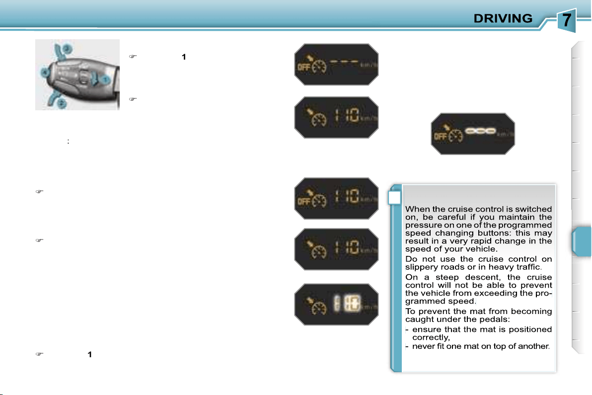
!
125
Programming
Turn dial
1
to the
"CRUISE"
posi-
tion: the cruise control mode is se-
lected but is not switched on (OFF).
Exceeding the programmed speed
Intentional or unintentional exceeding of the programmed
speed results in flashing of this speed on the display.
Return to the programmed speed, by means of intentional or
unintentional deceleration of the vehicle, automatically can-
cels the flashing of the speed.
Return to normal driving
Turn dial
1
to the
"0"
position: the cruise control mode is
deselected. The display returns to the distance recorder.
Operating fault
In the event of a cruise control mal-
function, the speed is cleared result-
ing in flashing of the dashes. Contact a
PEUGEOT dealer to have the system
checked.
Set the programmed speed by ac-
celerating to the required speed,
then press button
2
or
3
(e.g.:
70 mph (110 km/h)).
Switch off the cruise control by pressing button
4
: the
display confirms that it has been switched off (OFF).
Switch the cruise control back on by pressing button
4
again.
You can then change the programmed speed using buttons
2
and
3
:
- by + or - 1 mph (km/h) = short press,
- by + or - 5 mph (km/h) = long press,
- in steps of + or - 5 mph (km/h) = maintained press.
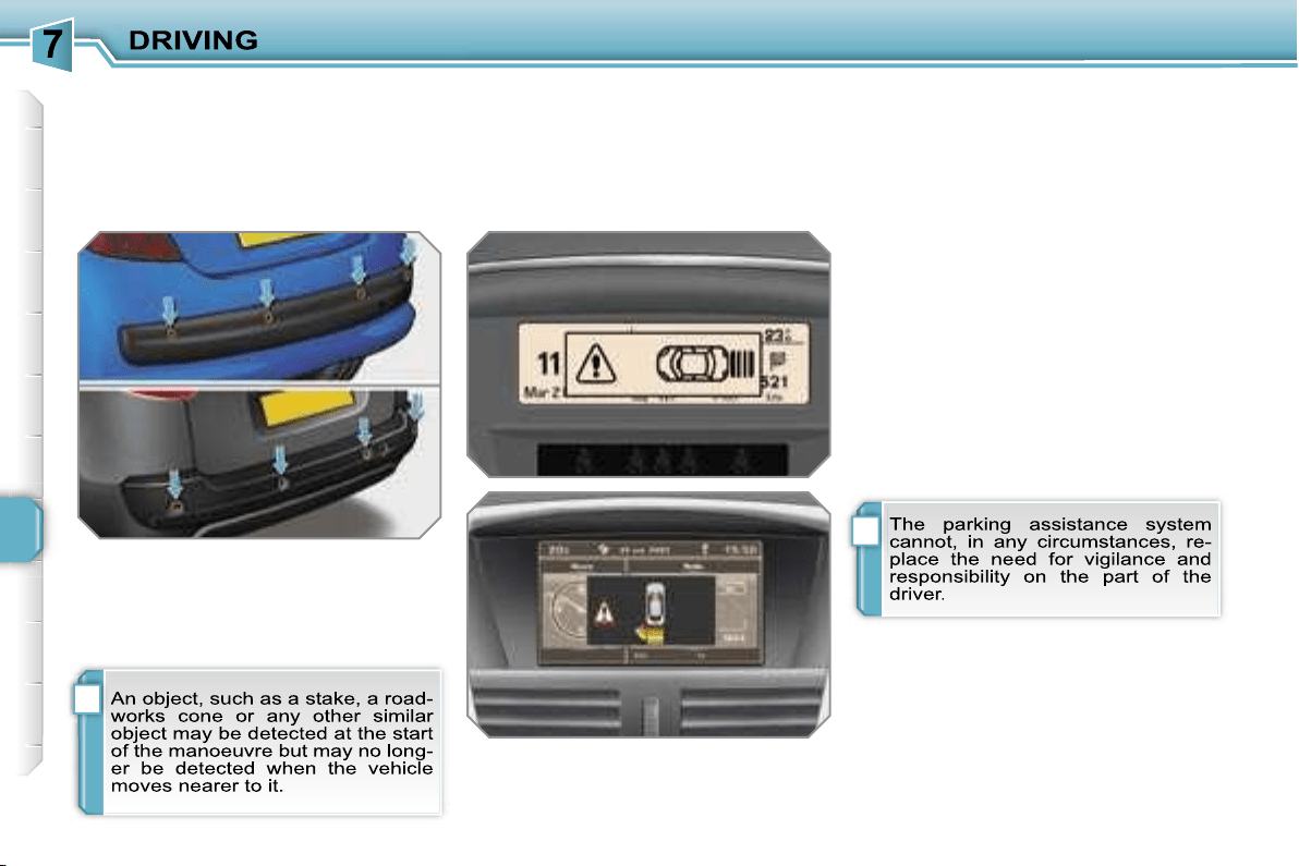
i
i
126
VISUAL AND AUDIBLE REAR
PARKING ASSISTANCE
System consisting of four proximity sen-
sors, installed in the rear bumper.
It detects any obstacle (person, vehicle,
tree, barrier...) located behind the vehi-
cle, however, it will not be able to detect
obstacles located immediately below
the bumper.
The parking assistance is
switched on
by engaging reverse gear.
This is accompanied by an audible signal.
* According to version.
The proximity information is indicated
by:
- an audible signal which becomes
more rapid as the vehicle approaches
the obstacle,
- a diagram on the multifunction dis-
play*, with blocks which move closer
to the vehicle.
When the distance between the rear
of the vehicle and the obstacle is less
than approximately thirty centimetres,
the audible signal becomes continu-
ous and the "Danger" symbol appears,
depending on the multifunction display
version.
The parking assistance is
switched off
by moving the gear lever to neutral.
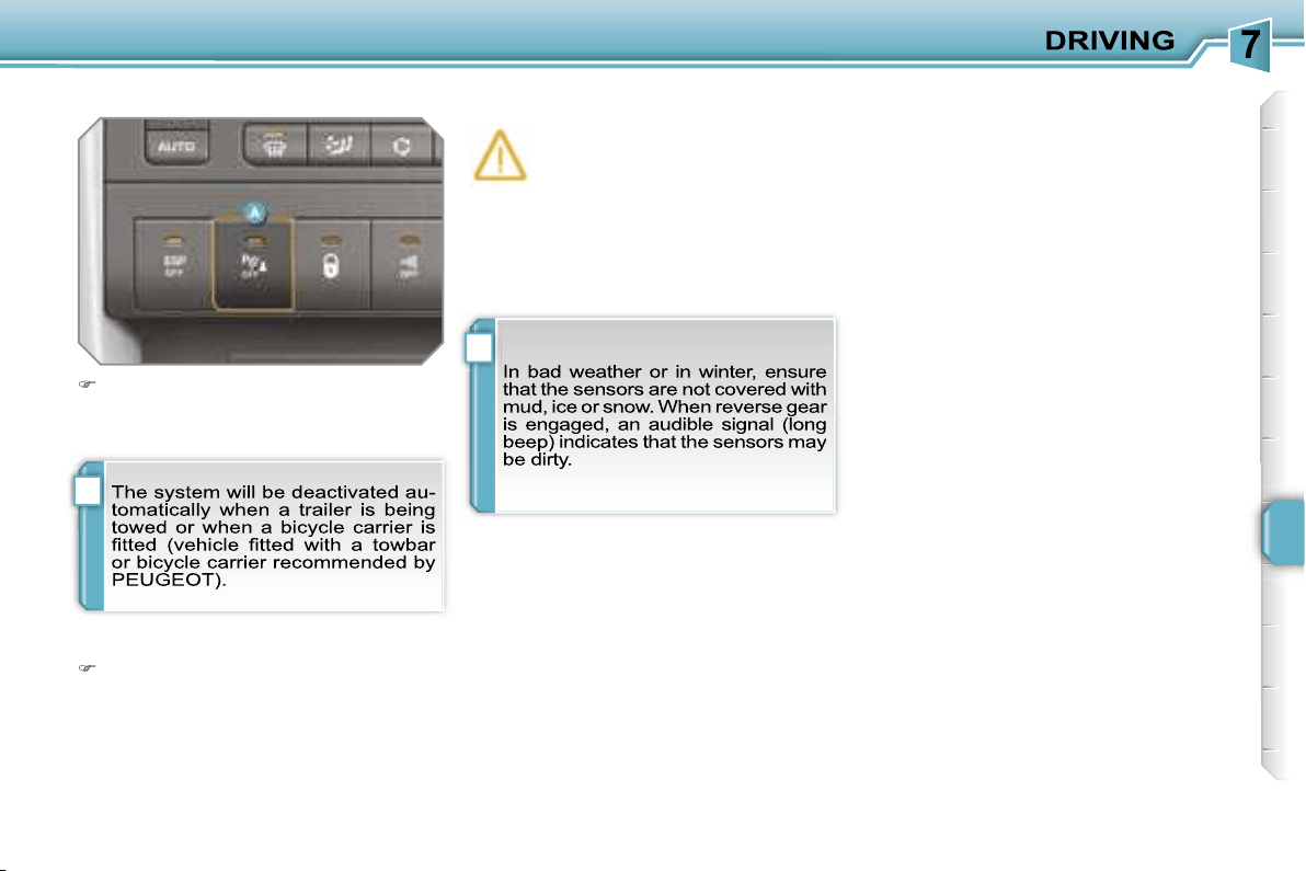
i
i
127
Deactivation
Operating fault
If an operating fault occurs, this
warning light comes on, when
reverse gear is engaged, ac-
companied by an audible signal
(short beep) and a message on the mul-
tifunction display.
Contact a PEUGEOT dealer.
Reactivation
Press button
A
again, the warning
light switches off, the system is reac-
tivated.
Press button
A
, the warning light
comes on, the system is fully deacti-
vated.
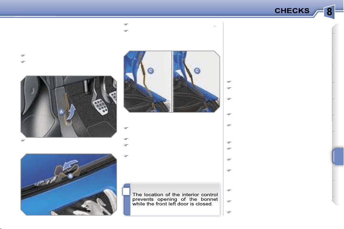
i
129
BONNET
Protects the components of the en-
gine and provides access for checking
levels.
Push the exterior control
B
to the left
and raise the bonnet.
Unclip the strut
C
from its housing
.
Fix the strut in one of the two notches
to hold the bonnet open.
Closing
Take the strut out of the support
notch.
Clip the strut in its housing.
Lower the bonnet and release it at
the end of its travel.
Pull on the bonnet to check that it is
secured correctly.
RUNNING OUT OF FUEL
(DIESEL)
If your vehicle is fitted with an HDI en-
gine, the fuel circuit must be reprimed
if you run out of fuel (refer to the corre-
sponding graphic).
This system consists of a repriming
pump and a transparent pipe.
Opening
Open the front left door.
Pull the interior control
A
, located at
the bottom of the door frame.
1.4 litre Turbo HDI engine
Open the bonnet.
Fill the fuel tank with at least five
litres of diesel.
Squeeze and release the repriming
pump until fuel appears in the trans-
parent pipe.
Operate the starter until the engine
starts.
Close the bonnet.
1.6 litre Turbo HDI 16V engine
Open the bonnet.
Fill the fuel tank with at least five
litres of diesel.
Unclip the style cover to gain access
to the repriming pump.
Squeeze and release the repriming
pump until fuel appears in the trans-
parent pipe with the green connec-
tor.
Operate the starter until the engine
starts.
Put the style cover back in position
and clip it in place.
Close the bonnet.
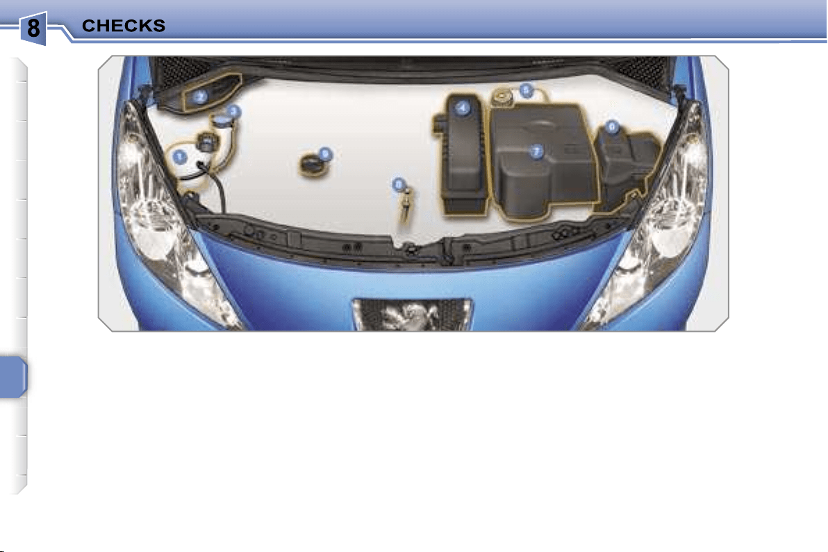
130
PETROL ENGINES
These allow you access to check the level of the various fluids and to replace certain components.
1.
Coolant reservoir.
2.
Passenger compartment filter.
3.
Wash-wipe and headlamp wash
reservoir.
4.
Air filter.
5.
Brake fluid reservoir.
6.
Fuse box.
7.
Battery.
8.
Dipstick.
9.
Engine oil filler cap.
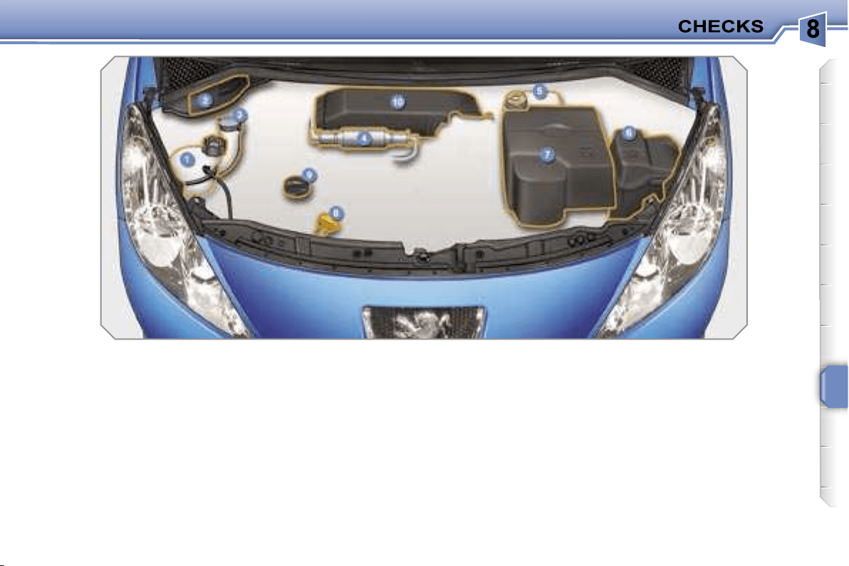
131
DIESEL ENGINES
These allow you access to check the level of the various fluids, to replace certain components and to reprime the fuel.
1.
Coolant reservoir.
2.
Passenger compartment filter.
3.
Wash-wipe and headlamp wash
reservoir.
4.
Repriming pump.
5.
Brake fluid reservoir.
6.
Fuse box.
7.
Battery.
8.
Dipstick.
9.
Engine oil filler cap.
10.
Air filter.
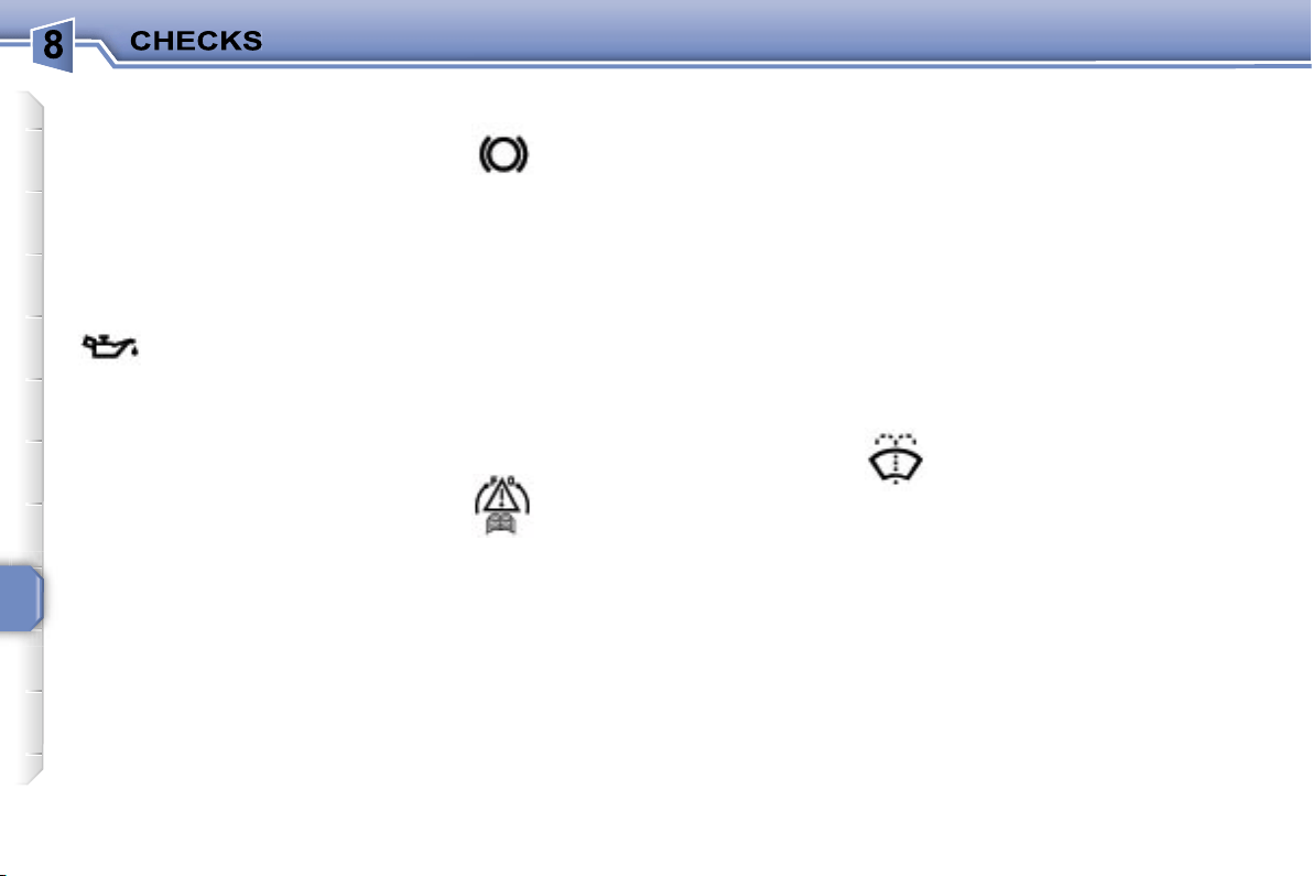
132
CHECKING LEVELS
Check all of these levels regularly and
top them up if necessary, unless other-
wise indicated.
If a level drops significantly, have the
corresponding circuit checked by a
PEUGEOT dealer.
Brake fluid level
To avoid any risk of scalding, unscrew
the cap by two turns to allow the pres-
sure to drop. When the pressure has
dropped, remove the cap and top up
the level.
Oil level
The reading will only be correct
if the vehicle is on level ground
and the engine has been off for
more than 15 minutes.
The check is carried out either when the
ignition is switched on using the oil level
indicator on the instrument panel, or
using the dipstick.
Between two oil changes, the consump-
tion should not exceed 0.5 litre per
600 miles (1,000 km).
The brake fluid level should be
close to the "MAX" mark. If it is
not, check the brake pad wear.
Draining the circuit
Refer to the servicing booklet for details
of the interval for this operation.
Coolant level
The coolant level should be
close to the "MAX" mark but
should never exceed it.
When the engine is warm, the tempera-
ture of the coolant is regulated by the fan.
This can operate with the ignition off.
On vehicles which are fitted with a par-
ticle emission filter, the fan may oper-
ate after the vehicle has been switched
off, even if the engine is cold.
In addition, as the cooling system is
pressurised, wait at least one hour after
switching off the engine before carrying
out any work.
Wash-wipe and headlamp wash*
fluid
The minimum level of this fluid
is indicated by an audible sig-
nal and a message on the multi-
function display.
Top up the level when you stop the ve-
hicle.
* According to country.
Draining the engine
Refer to the servicing booklet for details
of the interval for this operation.
In order to maintain the relia-
bility of the engine and emission control
system, the use of additives in the en-
gine oil is prohibited.
Oil specification
The oil must correspond to your engine
and conform to the manufacturer’s rec-
ommendations.
Fluid specification
The brake fluid must conform to the
manufacturer’s recommendations and
fulfil the DOT4 standards.
Draining the circuit
The coolant does not have to be
changed.
Fluid specification
The coolant must conform to the manu-
facturer’s recommendations.
Fluid specification
This fluid must conform to the manufac-
turer’s recommendations for optimum
cleaning.
!
i
133
Diesel additive level (Diesel with
particle emission filter)
The minimum level of this additive is in-
dicated by lighting of the service warn-
ing light, accompanied by an audible
signal and a message on the multifunc-
tion display.
Used products
CHECKS
Unless otherwise indicated, check
these components in accordance with
the servicing booklet and in relation to
your engine.
Otherwise, have them checked by a
PEUGEOT dealer.
Battery
The battery does not require
any maintenance.
However, check that the ter-
minals are clean and correctly
tightened, particularly in sum-
mer and winter.
When carrying out work on the battery,
refer to the "Practical information" sec-
tion for details of the precautions to be
taken before disconnecting the battery
and following its reconnection.
Air filter and passenger compartment filter
Refer to the servicing booklet
for details of the replacement
intervals for these compo-
nents.
Depending on the environ-
ment (dusty atmosphere...) and the use
of the vehicle (city driving...),
replace
them twice as often if necessary
(re-
fer to the "Engines" paragraph).
A clogged passenger compartment filter
may have an adverse effect on the per-
formance of the air conditioning system
and generate undesirable odours.
Particle emission filter (Diesel)
It is imperative that the maintenance of
the particle emission filter is carried out
by a PEUGEOT dealer.
Oil filter
Replace the oil filter each time
the engine oil is changed.
Refer to the servicing booklet
for details of the replacement
interval for this component.
Topping up
It is imperative that this additive is
topped up by a PEUGEOT dealer with-
out delay.
!
134
Automatic gearbox
The gearbox does not re-
quire any maintenance (no oil
change).
Refer to the servicing booklet
for details of the level checking
intervals for this component.
Brake disc drum wear status
For any information relating
to checking of the brake disc
and/or drum wear status, con-
tact a PEUGEOT dealer.
Manual gearbox
The gearbox does not re-
quire any maintenance (no oil
change).
Refer to the servicing booklet
for details of the level checking
intervals for this component.
Brake pads
Brake wear depends on the
style of driving, particularly in
the case of vehicles used in
town, over short distances. It
may be necessary to have the
condition of the brakes checked, even
between vehicle services.
Unless there is a leak on the circuit, a
drop in the brake fluid level indicates
that the brake pads are worn.
Handbrake
If the handbrake travel is too
long or if you notice a loss
of effectiveness of this sys-
tem, the handbrake must be
adjusted, even between two
services.
This system must be checked by a
PEUGEOT dealer.
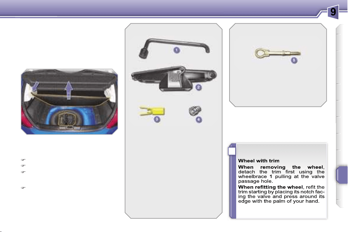
i
PRACTICAL INFORMATION
135
CHANGING A WHEEL
Procedure for changing a faulty wheel
for the spare wheel using the tools
provided with the vehicle.
The tools are installed in the boot under
the floor.
To gain access to them:
open the boot,
raise the floor,
secure it by hooking the cord(s) on
the hook(s) on the rear shelf sup-
port,
remove the box containing the tools.
1.
Wheelbrace.
Permits removal of the wheel
trim and removal of the wheel
fixing bolts.
2.
Jack with integral handle.
Permits raising of the vehicle.
3.
"Bolt cover" tool.
Permits removal of the bolt pro-
tectors (covers) on alloy wheels.
4.
Socket for the anti-theft bolts
(located in the glove box).
Permits adaptation of the wheel-
brace to the special "anti-theft"
bolts.
List of tools
Other accessories
5.
Removable towing eye.
Refer to the paragraph "Towing
the vehicle".
Access to the tools
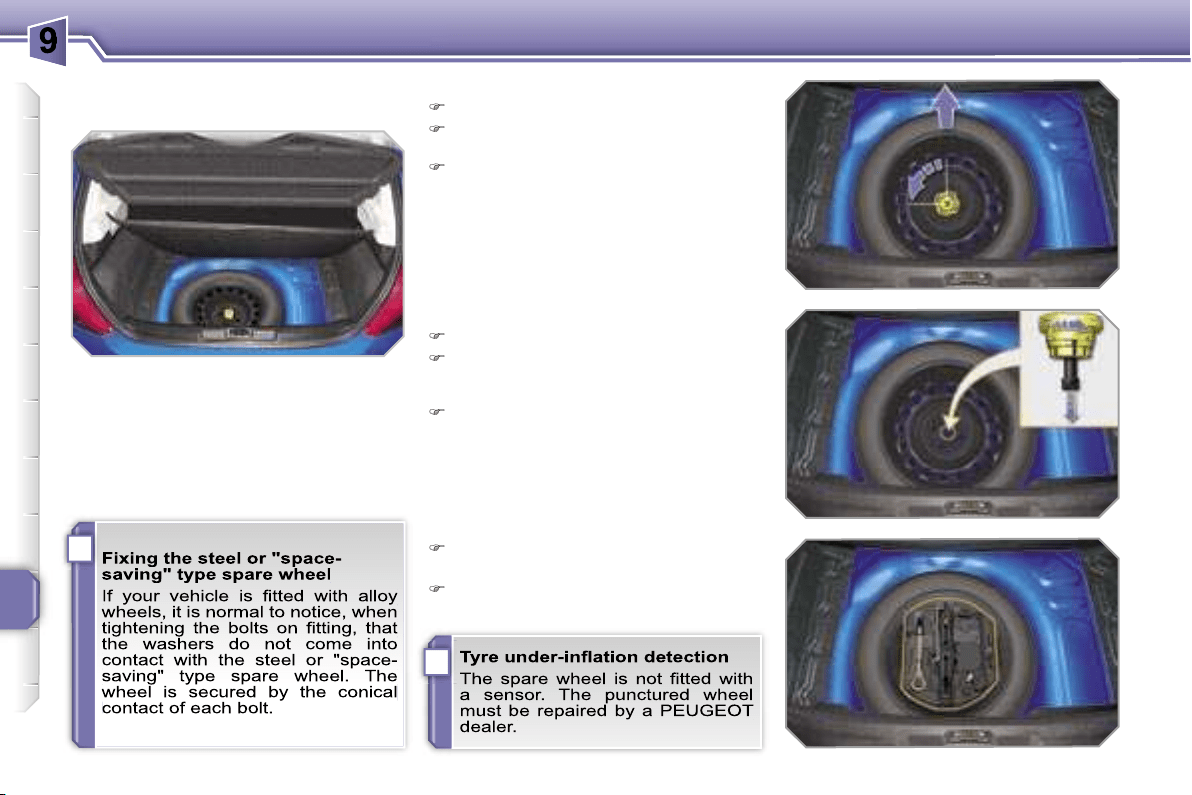
i
i
PRACTICAL INFORMATION
136
Access to the spare wheel
(Saloon)
The spare wheel is installed in the boot
under the floor.
According to model, the spare wheel may
be steel or of the "space saving" type.
To gain access to it, refer to the para-
graph "Access to the tools" on the pre-
vious page.
Taking out the wheel
Unscrew the yellow central bolt.
Raise the spare wheel towards you
from the rear.
Take the wheel out of the boot.
Putting the wheel back in place
Put the wheel back in its housing.
Unscrew the yellow central bolt by a
few turns then put it in place in the
centre of the wheel.
Tighten fully until the central bolt
clicks to retain the wheel correctly.
Put the box back in place in the
centre of the wheel.
Put the boot floor back in place.
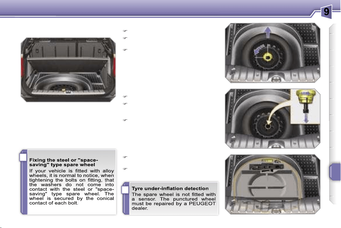
i
i
PRACTICAL INFORMATION
137
Access to the spare wheel (SW)
The spare wheel is installed in the boot
under the floor.
According to model, the spare wheel may
be steel or of the "space saving" type.
To gain access to it, refer to the para-
graph "Access to the tools".
Taking out the wheel
Unscrew the yellow central bolt.
Raise the spare wheel towards you
from the rear.
Take the wheel out of the boot.
Putting the wheel back in place
Put the wheel back in its housing.
Unscrew the yellow central bolt by a
few turns then put it in place in the
centre of the wheel.
Tighten fully until the central bolt
clicks to retain the wheel correctly.
Put the box back in place in the cen-
tre of the wheel.
Put the boot floor back in place.
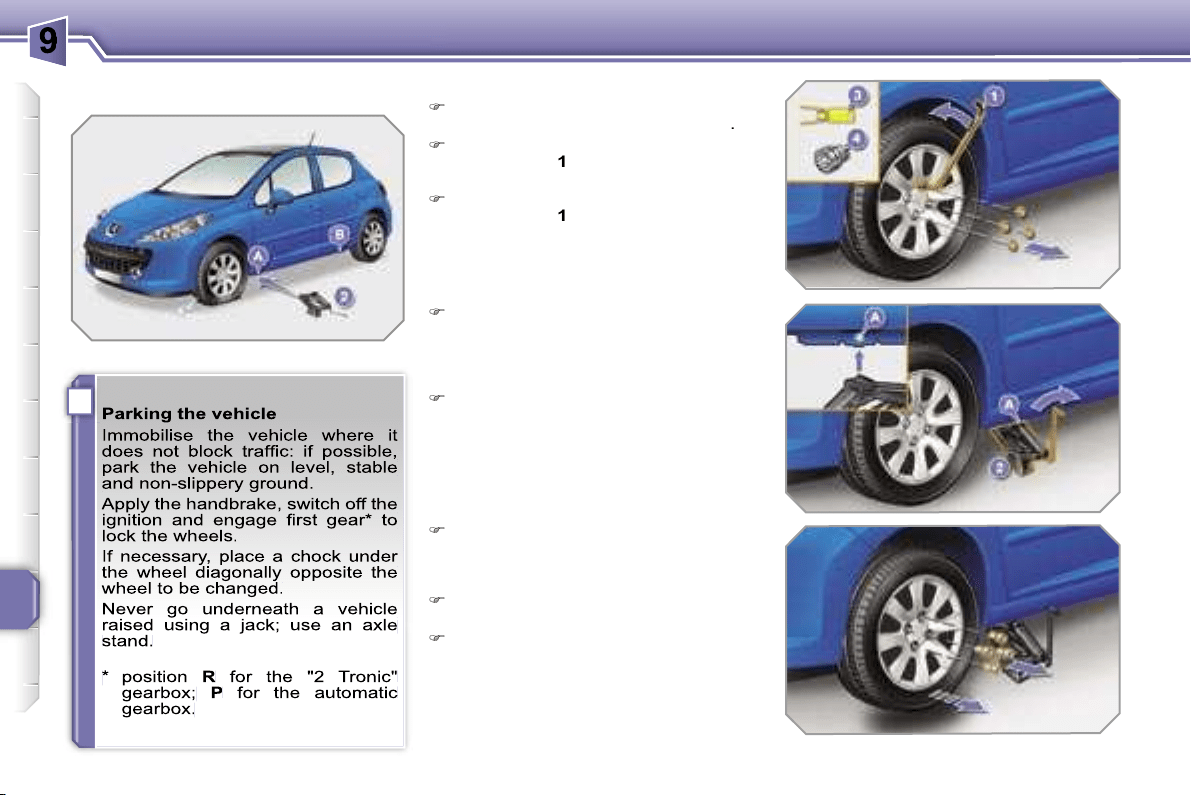
i
PRACTICAL INFORMATION
138
Removing the wheel
List of operations
Remove the chromed bolt cover from
each of the bolts using the tool
3
.
Fit the anti-theft socket
4
on the
wheelbrace
1
to unlock the anti-theft
bolt.
Unlock the other bolts using the
wheelbrace
1
only.
Place the jack
2
in contact with one
of the two front
A
or rear
B
locations
provided on the underframe, which-
ever is closest to the wheel to be
changed.
Extend the jack
2
until its base plate
is in contact with the ground. Ensure
that the centreline of the jack base
plate is directly below the location
A
or
B
used.
Raise the vehicle until there is suf-
ficient space between the wheel and
the ground to admit the spare (not
punctured) wheel easily.
Remove the bolts and store them in
a clean place.
Remove the wheel.
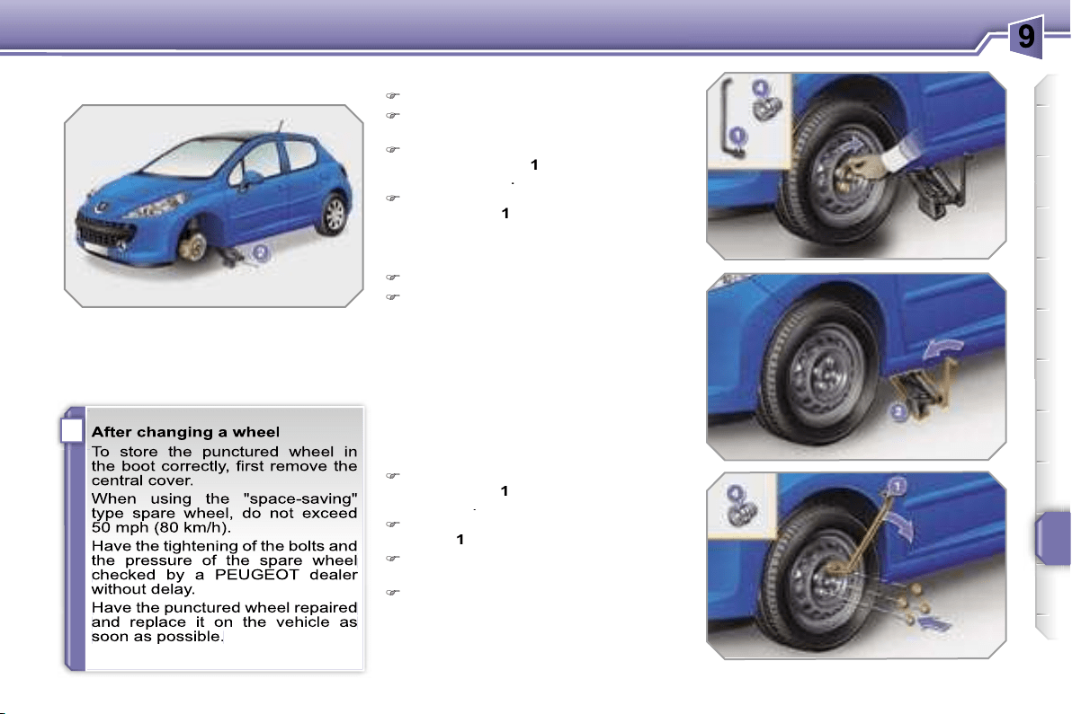
i
PRACTICAL INFORMATION
139
Fitting the wheel
List of operations
Put the wheel in place on the hub.
Screw in the bolts by hand to the
stop.
Pre-tighten the anti-theft bolt using
the wheelbrace
1
fitted with the anti-
theft socket
4
.
Pre-tighten the other bolts using the
wheelbrace
1
only.
Lower the vehicle fully.
Fold the jack
2
and detach it.
Lock the anti-theft bolt using the
wheelbrace
1
fitted with the anti-theft
socket
4
.
Lock the other bolts using the wheel-
brace
1
only.
Refit the chromed bolt covers on
each of the bolts.
Store the tools in the box.
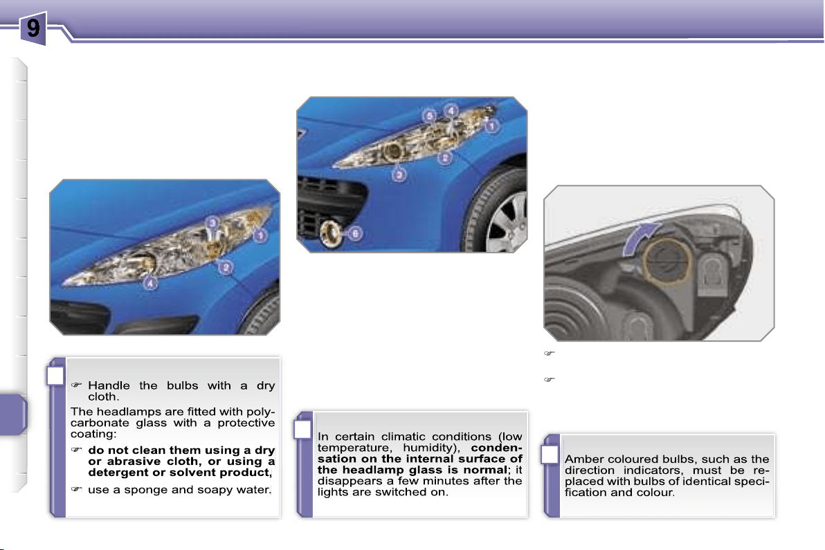
!
i
i
PRACTICAL INFORMATION
140
CHANGING A BULB
Procedure for the replacement of a
faulty bulb with a new bulb without the
use of tools.
1. Direction indicators
(PY 21 W amber).
2. Side lights (W 5 W).
3. Dipped headlamps (H7-55 W).
4. Main beam headlamps (H1-55 W).
5. Directional headlamps
(H7-55 W).
6. Fog lamps (H11-55 W).
Changing the direction indicators
Model with dipped headlamps with
elliptical module and directional
headlamps
Turn the bulb holder one quarter of a
turn and remove it.
Pull the bulb then change it.
To refit, carry out these operations in
reverse order.
Front lights
Model with conventional lights
Blown bulb
A message appears on the multifunc-
tion display to indicate the bulb to be
changed.
Refer to the appropriate procedure to
change the corresponding bulb.
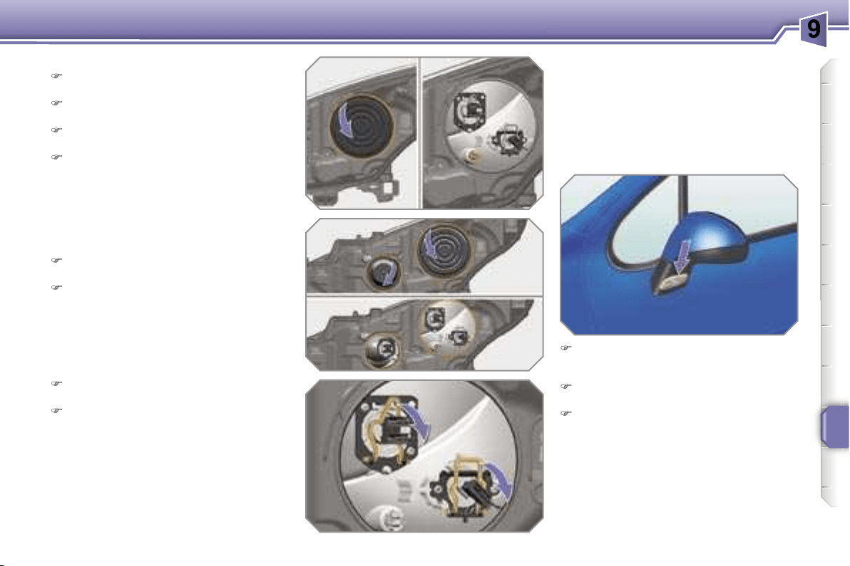
PRACTICAL INFORMATION
141
Changing the side lights
Disconnect the main headlamp con-
nector.
Remove the plastic protective cover
by pulling on the tab.
Turn the bulb holder one quarter of a
turn and remove it.
Pull the bulb and change it.
To refit, carry out these operations in
reverse order.
Changing the dipped headlamps,
main beam headlamps or directional
headlamps
Disconnect the main headlamp con-
nector.
Remove the corresponding plastic
protective cover by pulling on the
tab.
Changing the integrated direction
indicator side repeaters
Insert a screwdriver towards the
centre of the repeater between the
repeater and the base of the mirror.
Tilt the screwdriver to extract the re-
peater and remove the repeater.
Disconnect the repeater connector.
To refit, carry out these operations in re-
verse order.
To obtain a replacement repeater, con-
tact a PEUGEOT dealer.
Disconnect the connector of the cor-
responding light.
Move aside the spring to release the
bulb and remove the bulb.
To refit, carry out these operations in re-
verse order.
Changing the fog lamps
For replacement of these bulbs, contact
a PEUGEOT dealer.
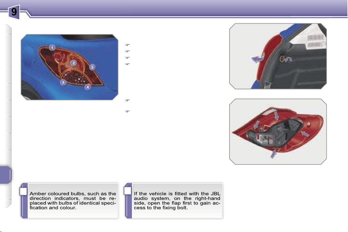
i
i
PRACTICAL INFORMATION
142
Rear lights (Saloon)
1. Brake lights (P 21 W).
2. Side lights (R 5 W).
3. Fog lamps (P 21 W).
4. Direction indicators
(PY 21 W amber).
5. Reversing lights (P 21 W).
Changing bulbs
These five bulbs are changed from out-
side the boot:
remove the light fixing bolt,
take out the light from the outside,
disconnect the light connector,
remove the light seal,
press the four tabs and remove the
bulb holder,
turn the bulb one quarter of a turn
and change it.
To refit, carry out these operations in re-
verse order.
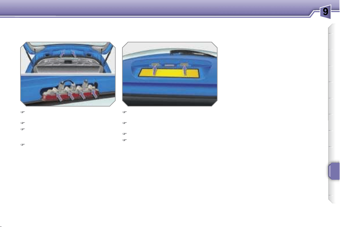
PRACTICAL INFORMATION
143
Changing the third brake light bulbs
(4 bulbs W 5 W)
Press on the fixing pins on each side
of the light.
Take out the light from the outside.
Turn the bulb holder which corre-
sponds to the faulty bulb one quarter
of a turn and remove it.
Pull the bulb and change it.
To refit, carry out these operations in re-
verse order.
Changing the number plate light
bulbs (W 5 W)
Insert a thin screwdriver in one of the
exterior holes of the lens.
Push it towards the outside to unclip
it.
Remove the lens.
Pull the bulb and change it.
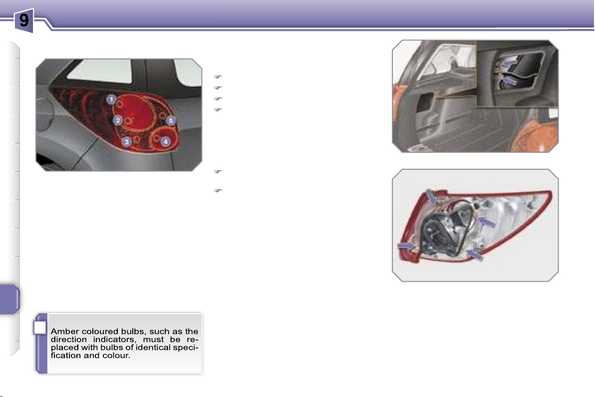
i
PRACTICAL INFORMATION
144
Rear lights (SW)
1. Brake lights (P 21 W).
2. Side lights (R 5 W).
3. Direction indicators
(PY 21 W amber).
4. Fog lamps (P 21 W).
5. Reversing lights (P 21 W).
Changing bulbs
These five bulbs are changed from out-
side the boot:
remove the access flap,
disconnect the light connector,
remove the light fixing bolt,
take out the light from the outside,
press on the four tabs and remove
the bulb holder,
turn the bulb a quarter of a turn and
change it.
To refit, carry out these operations in re-
verse order.
Take care to engage the light in its
guides keeping it in the centreline of the
vehicle.
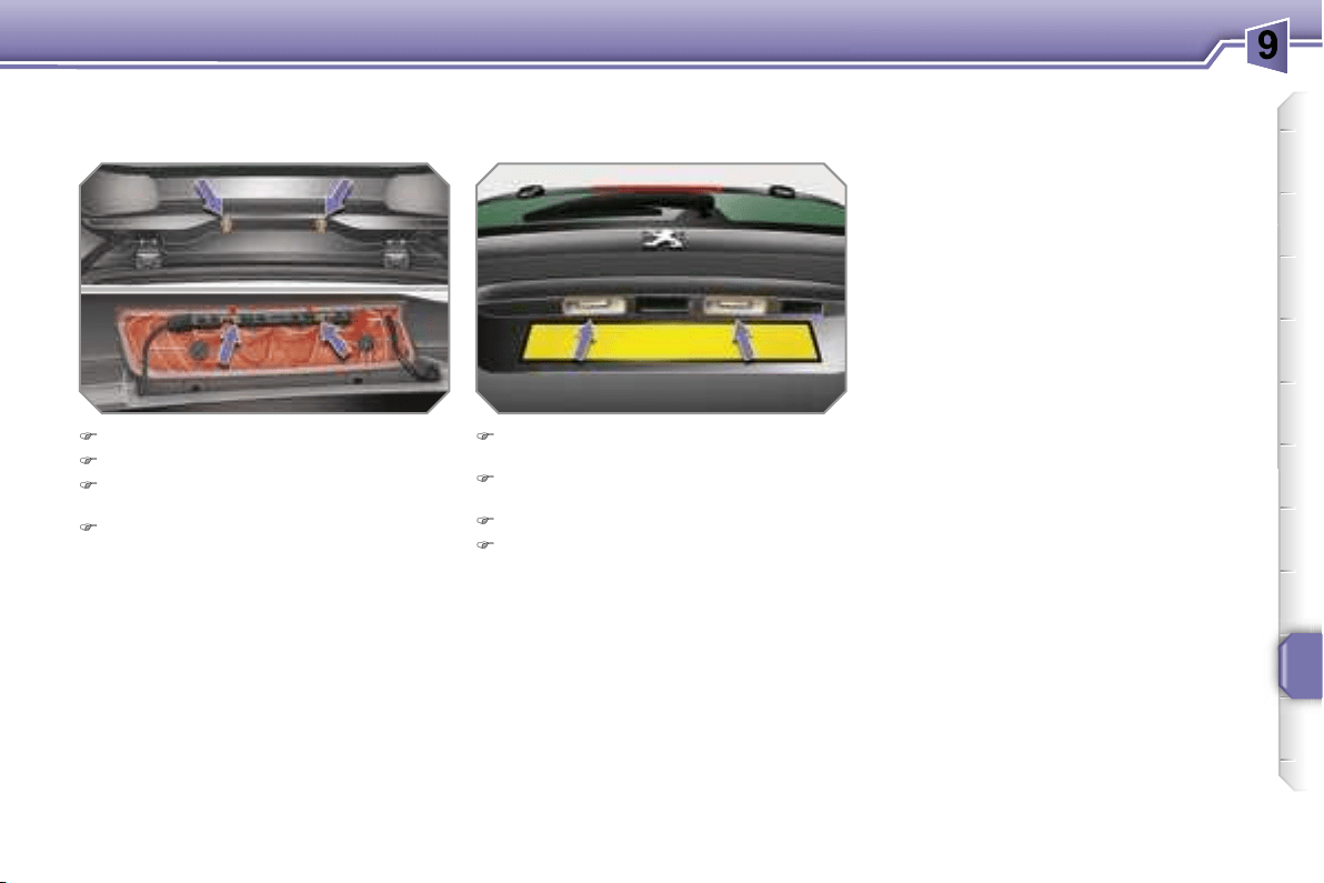
PRACTICAL INFORMATION
145
Changing the third brake light bulbs
(4 bulbs W 5 W)
Remove the two light fixing nuts.
Take out the light from the outside.
Press on the two tabs and remove
the bulb holder.
Pull the bulb and change it.
To refit, carry out these operations in re-
verse order.
Changing the number plate bulbs
(W 5 W)
Insert a thin screwdriver into one of
the exterior holes of the lens.
Push it towards the outside to unclip
it.
Remove the lens.
Pull the bulb and change it.

!
i
PRACTICAL INFORMATION
146
CHANGING A FUSE
Procedure for the replacement of a
faulty fuse with a new fuse in order to
rectify a failure of the corresponding
function.
Access to the tools
The extraction pliers are installed on the
back of the fascia fuse box cover.
To gain access to them:
unclip the cover pulling at the top,
remove the cover completely,
remove the pliers.
Replacing a fuse
Before replacing a fuse, the cause of
the failure must be identified and recti-
fied.
Identify the faulty fuse by examining
the condition of its filament.
Use the special pliers to extract the
fuse from its housing.
Always replace the faulty fuse with a
fuse of the same rating.
Check that the number engraved
on the box and the rating engraved
on the top correspond to the tables
which follow.
Correct
Incorrect
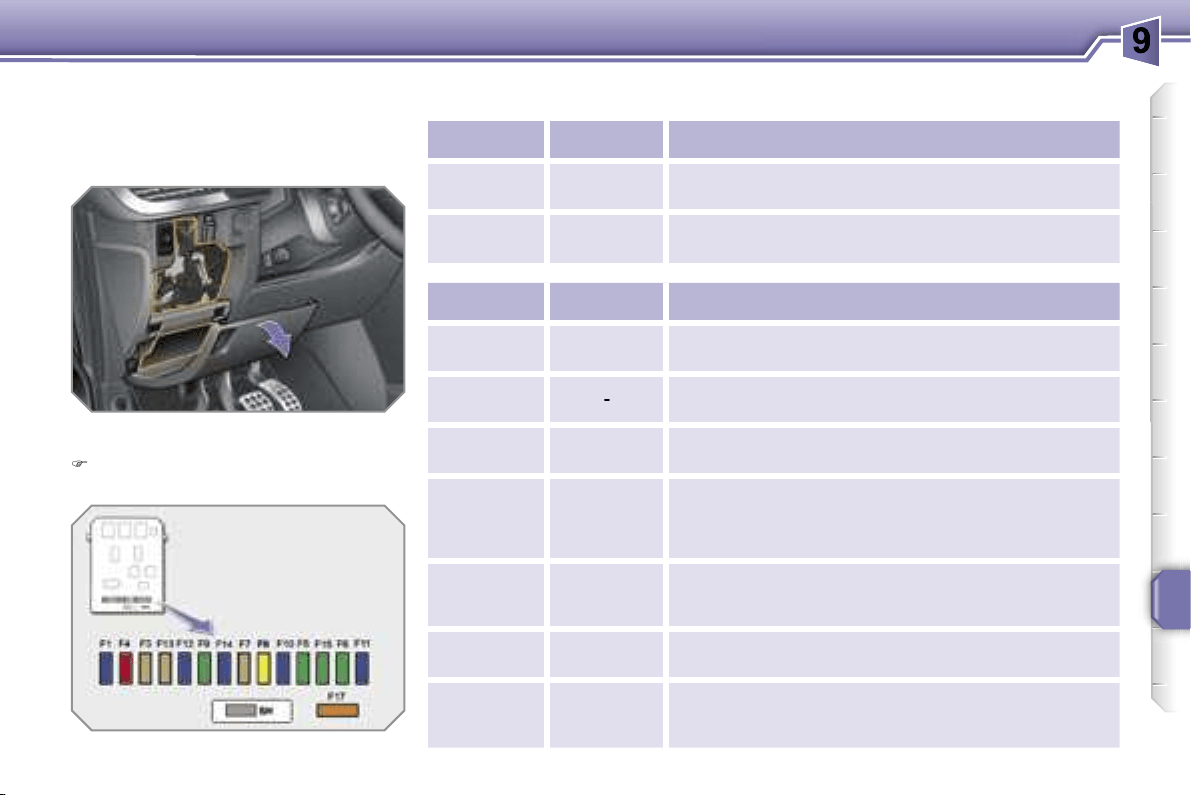
PRACTICAL INFORMATION
147
Fascia fuses
The fuse box is placed in the lower part
of the fascia (left-hand side).
Access to the fuses
refer to the "Access to the tools"
paragraph.
Fuse tables
Fuse N°
Rating
Functions
G39
20 A
Hi-Fi amplifier.
G40
20 A
Driver and passenger heated seats.
Fuse N°
Rating
Functions
F1
15 A
Rear wiper.
F2
-
Not used.
F3
5 A
Air bags and pre-tensioners control unit.
F4
10 A
Clutch pedal switch, diagnostic socket,
electrochromatic interior mirror, air conditioning,
steering wheel angle sensor, particle emission filter
pump (Diesel).
F5
30 A
Electric windows, rear one-touch electric
windows, sunroof, panoramic roof shutter (SW).
F6
30 A
Front one-touch electric windows, folding mirrors
supply.
F7
5 A
Front and rear courtesy lights, map reading
lights, sun visor lighting, glove box lighting, clock.
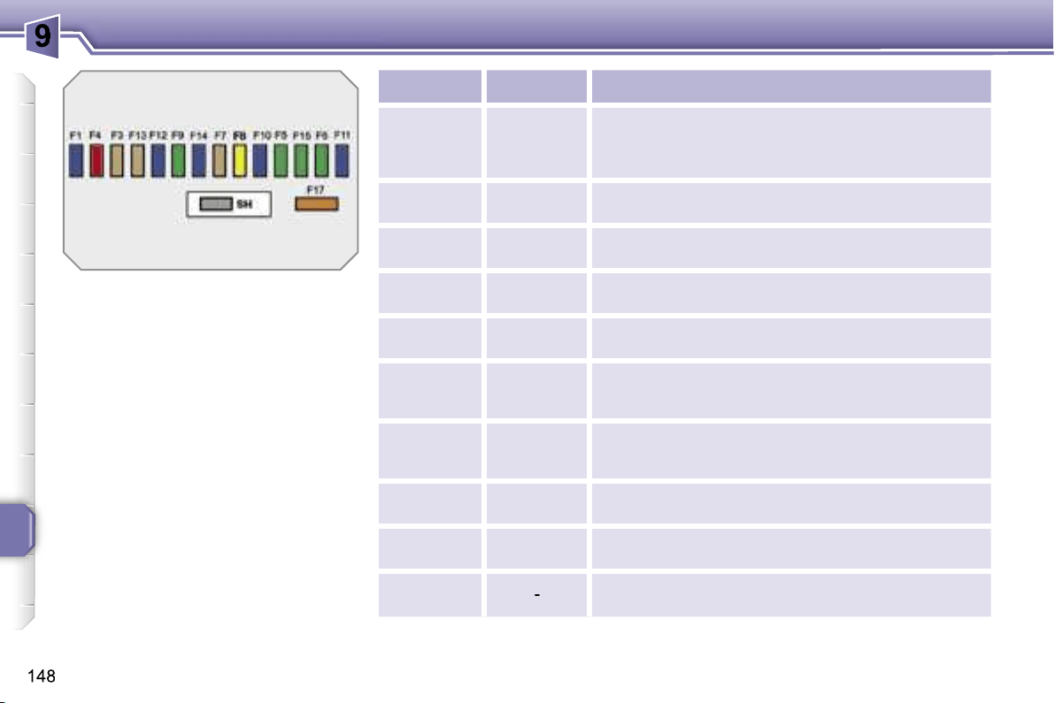
PRACTICAL INFORMATION
Fuse N°
Rating
Functions
F8
20 A
Audio equipment, audio/telephone, CD changer,
multifunction display, clock, steering wheel controls,
tyre under-inflation detection, trailer fuse box.
F9
30 A
Front 12 V socket.
F10
15 A
Alarm siren, alarm control unit, directional
headlamps.
F11
15 A
Diagnostic socket, low current ignition switch,
automatic gearbox control unit.
F12
15 A
Rain/brightness sensor, amplifier, trailer fuse box,
driving school module.
F13
5 A
Engine fuse box, ABS relay, "2 Tronic" gearbox
selector lever, dual-function brake switch.
F14
15 A
Instrument panel, seat belt warning lights bar,
headlamp adjustment, air conditioning, hands-free
kit, rear parking assistance control unit, air bags.
F15
30 A
Locking and deadlocking.
F17
40 A
Rear screen and exterior mirrors de-icing.
SH
-
PARC shunt.
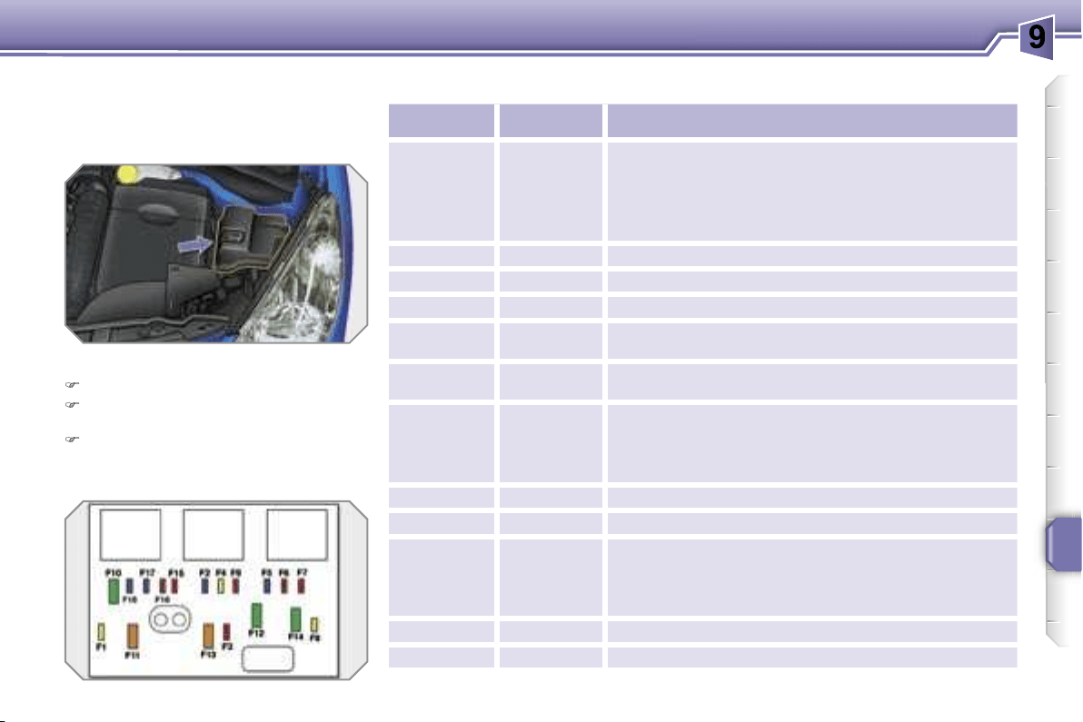
PRACTICAL INFORMATION
149
Engine compartment fuses
The fuse box is placed in the engine
compartment, near the battery (left-
hand side).
Access to the fuses
Unclip the cover.
Replace the fuse (refer to the corre-
sponding paragraph).
When you have finished, close the
cover carefully to guarantee the
sealing of the fuse box.
Fuse table
Fuse N°
Rating
Functions
F1
20 A
Engine control unit and fan assembly control
relay supply, timing and canister solenoid valves
(1.6 l 16V THP), air flow sensor (Diesel), injection
pump (Diesel), water in diesel sensor (Diesel),
EGR solenoid valves, air heating (Diesel).
F2
15 A
Horn.
F3
10 A
Front and rear wash-wipe.
F4
20 A
Headlamp wash.
F5
15 A
Fuel pump (petrol), Turbo solenoid valves
(1.6 l 16V THP).
F6
10 A
Vehicle speed sensor, automatic gearbox.
F7
10 A
Electric power steering, directional headlamps,
directional headlamps control relay, switching and
protection unit (Diesel).
F8
20 A
Starter control.
F9
10 A
ABS/ESP control unit, brake pedal switch.
F10
30 A
Engine control unit actuators (petrol: ignition
coils, solenoid valves, oxygen sensors, injectors,
heaters, controlled thermostat) (Diesel: solenoid
valves, heaters).
F11
40 A
Air conditioning blower.
F12
30 A
Windscreen wipers Low/High speed.
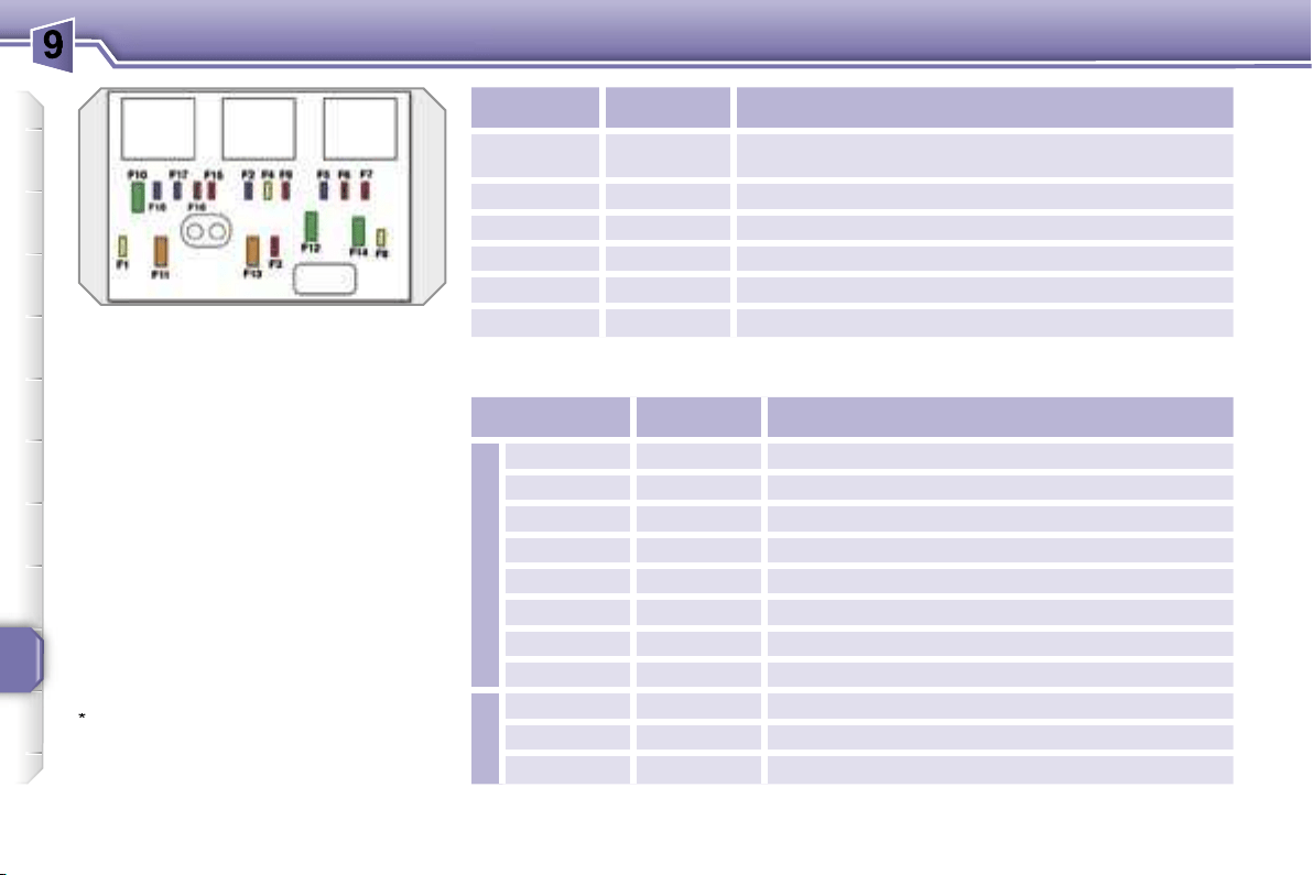
PRACTICAL INFORMATION
150
Fuse N°
Rating
Functions
F13
40 A
Built-in systems interface supply (ignition positive).
F14
30 A
Diesel heater (Diesel).
F15
10 A
Left main beam headlamp.
F16
10 A
Right main beam headlamp.
F17
15 A
Left dipped beam headlamp.
F18
15 A
Right dipped beam headlamp.
Maxi-fuse table
*
The maxi-fuses provide additional
protection for the electrical systems.
All work on the maxi-fuses must be
carried out by a PEUGEOT dealer.
Fuse N°
Rating
Functions
Box 1
MF1*
70 A
Fan assembly.
MF2*
20 A/30 A
ABS/ESP pump.
MF3*
20 A/30 A
ABS/ESP solenoid valves.
MF4*
60 A
Built-in systems interface supply.
MF5*
60 A
Built-in systems interface supply.
MF6*
30 A
Additional fan assembly (1.6 l 16V THP).
MF7*
80 A
Passenger compartment fuse box.
MF8*
30 A
"2 Tronic" gearbox control unit.
Box 2
MF9*
80 A
Heating unit (Diesel).
MF10*
80 A
Electric power steering.
MF11*
40 A
Valvetronic electric motor (1.6 l 16V THP).
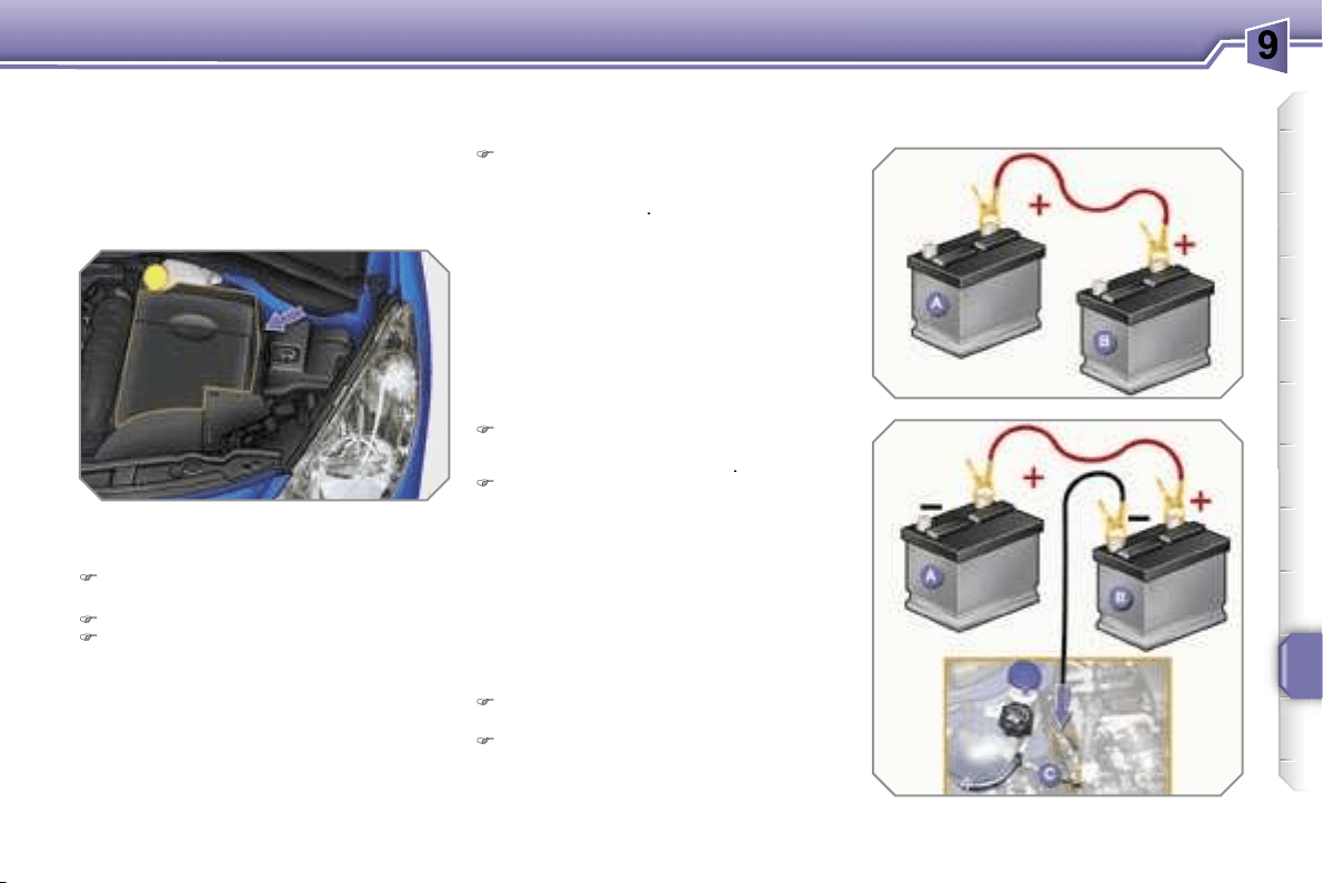
PRACTICAL INFORMATION
151
BATTERY
Procedure for charging your battery
when it is flat or for starting the engine
using another battery.
Access to the battery
Starting using another battery
Connect the red cable to the positive
terminal (+) of the flat battery
A
, then
to the positive terminal (+) of the
slave battery
B
.
Connect one end of the green or
black cable to the negative terminal
(-) of the slave battery
B
.
Connect the other end of the green
or black cable to an earth point
C
on
the broken down vehicle, as far as
possible from the battery (for exam-
ple, right-hand engine mounting).
Operate the starter, let the engine
run.
Wait until the engine returns to idle
and disconnect the cables.
The battery is located under the bonnet
on the left.
To gain access to it:
open the bonnet using the interior
lever, then the exterior lever,
secure the bonnet strut,
remove the plastic cover to gain
access to the two terminals.
!
!
i
PRACTICAL INFORMATION
152
Charging the battery using a
battery charger
Disconnect the battery from the vehicle.
Follow the instructions for use pro-
vided by the manufacturer of the
charger.
Reconnect starting with the negative
terminal (-).
Check that the terminals and con-
nectors are clean. If they are cov-
ered with sulphate (whitish or green-
ish deposit), remove them and clean
them.
LOAD REDUCTION MODE
System which manages the use of cer-
tain functions in relation to the level of
charge remaining in the battery.
When the vehicle is being driven, the load
reduction function temporarily deactivates
certain functions, such as the air condi
tioning, the rear screen de-icing...
The deactivated functions are reactivat-
ed automatically as soon as conditions
permit.

!
!
i
PRACTICAL INFORMATION
152
Charging the battery using a
battery charger
Disconnect the battery from the vehicle.
Follow the instructions for use pro-
vided by the manufacturer of the
charger.
Reconnect starting with the negative
terminal (-).
Check that the terminals and con-
nectors are clean. If they are cov-
ered with sulphate (whitish or green-
ish deposit), remove them and clean
them.
LOAD REDUCTION MODE
System which manages the use of cer-
tain functions in relation to the level of
charge remaining in the battery.
When the vehicle is being driven, the load
reduction function temporarily deactivates
certain functions, such as the air condi
tioning, the rear screen de-icing...
The deactivated functions are reactivat-
ed automatically as soon as conditions
permit.
!
i
PRACTICAL INFORMATION
153
ENERGY ECONOMY MODE
System which manages the duration of
use of certain functions to conserve a
sufficient level of charge in the battery.
After the engine has stopped, you can
still use functions such as the audio
equipment, windscreen wipers, dipped
headlamps, courtesy lights, etc. for a
maximum combined duration of thirty
minutes.
Exiting economy mode
These functions are reactivated auto-
matically next time the vehicle is driven.
In order to resume the use of these
functions immediately, start the en-
gine and let it run for a few minutes.
The time available to you will then be
double the duration for which the en-
gine is left running. However, this period
will always be between five and thirty
minutes.
Switching to economy mode
Once the thirty minutes are over, a
message appears on the multi-function
display indicating that the vehicle has
switched to economy mode and the ac-
tive functions are put on standby.
CHANGING A WIPER BLADE
Procedure for replacing a worn wiper
blade with a new one without the use
of tools.
Removing a front or rear wiper
blade
Raise the corresponding wiper arm.
Unclip the wiper blade and remove it.
Fitting a front or rear wiper
blade
At the front, check the size of the wip-
er blade as the shorter blade is fitted
on the right-hand side of the vehicle.
Put the corresponding new wiper
blade in place and clip it.
Fold down the wiper arm carefully.
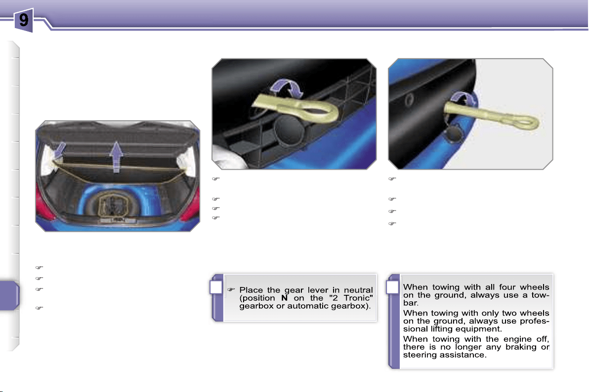
!
i
PRACTICAL INFORMATION
154
TOWING THE VEHICLE
Procedure for having your vehicle towed
or for towing another vehicle using a re-
movable towing eye.
Access to the tools
Towing your vehicle
On the front bumper, unclip the cover
by pressing at the bottom.
Screw the towing eye in fully.
Install the towbar.
Switch on the hazard warning lights
on the towed vehicle.
On the rear bumper, unclip the cover
by pressing at the bottom.
Screw the towing eye in fully.
Install the towbar.
Switch on the hazard warning lights
on the towed vehicle.
Towing another vehicle
The towing eye is installed in the boot
under the floor.
To gain access to it:
open the boot,
raise the floor,
secure it by hooking its cord on the
hook on the shelf support,
remove the towing eye from the
holder.
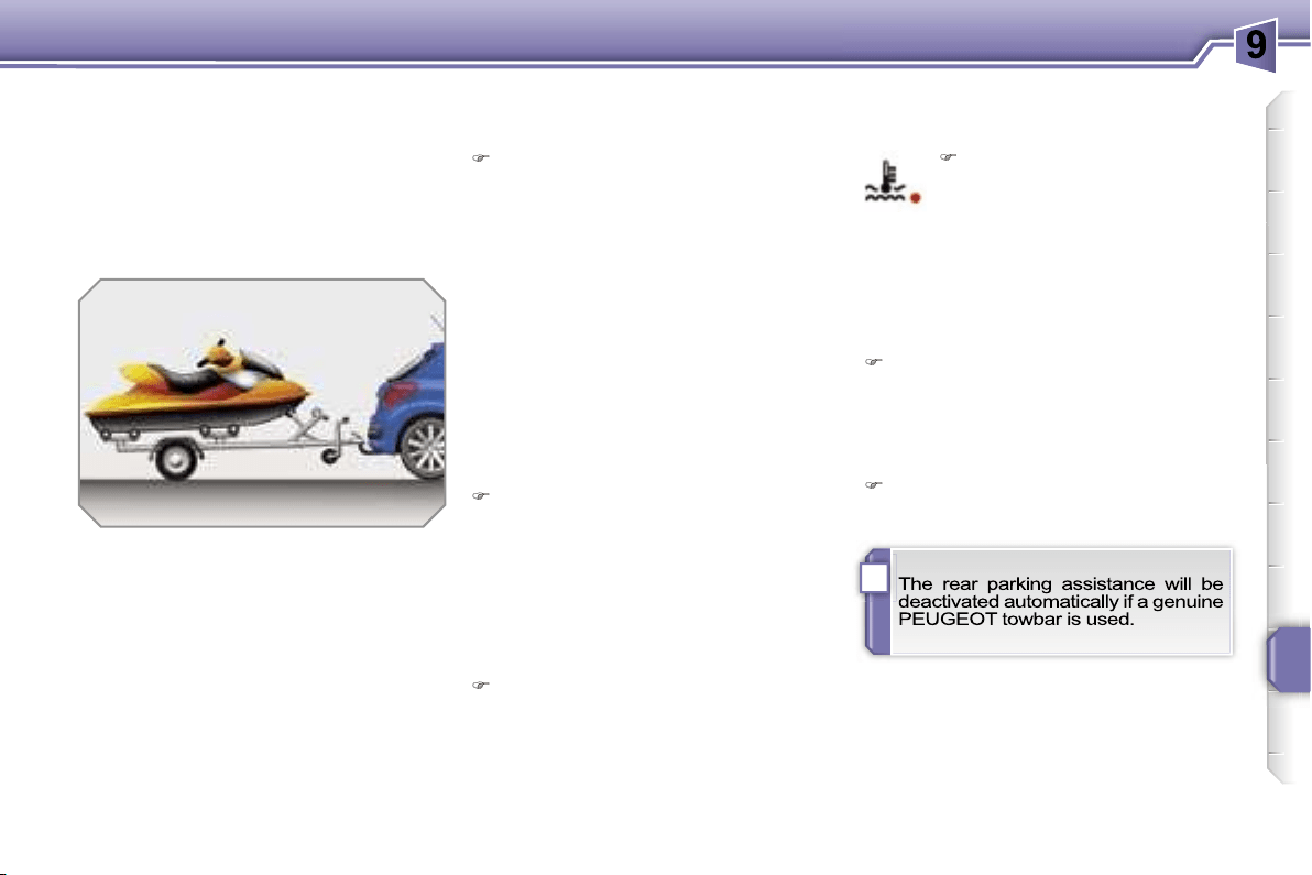
i
PRACTICAL INFORMATION
155
TOWING A TRAILER,
CARAVAN, etc.
Towbar suited to the attachment of a
trailer or caravan with additional signal-
ling and lighting.
Your vehicle is primarily designed for
transporting people and luggage, but it
may also be used for towing a trailer.
We recommend the use of original
PEUGEOT towbars that have been
tested and approved from the design
stage of your vehicle and that the fit-
ting of the towbar is entrusted to a
PEUGEOT dealer.
Driving with a trailer subjects the towing
vehicle to more significant stress and its
driver must be particularly careful.
Driving advice
Distribution of loads
Distribute the load in the trailer so
that the heaviest items are as close
as possible to the axle and the nose
weight approaches the maximum
permitted without exceeding it.
Air density decreases with altitude, thus
reducing engine performance. Above
1 000 metres, the maximum towing load
must be reduced by 10 % and so on for
every 1 000 metres of altitude.
Refer to the "Technical Data" section for
details of the weights and towing loads
which apply to your vehicle.
In all cases, pay attention to the coolant
temperature.
Side wind
Take into account the increased sen-
sitivity to side wind.
Cooling
Towing a trailer on a slope increases
the temperature of the coolant.
As the fan is electrically controlled, its
cooling capacity is not dependent on
the engine speed.
To lower the engine speed, reduce
your speed.
The maximum towing load on a long
slope depends on the gradient and the
outside temperature.
Braking
Towing a trailer increases the brak-
ing distance.
Tyres
Check the tyre pressures of the tow-
ing vehicle and of the trailer, observ-
ing the recommended pressures.
Lights
Check the electrical signalling on the
trailer.
If the warning light and the
STOP
warning light come on,
stop the vehicle and switch off
the engine as soon as possible.
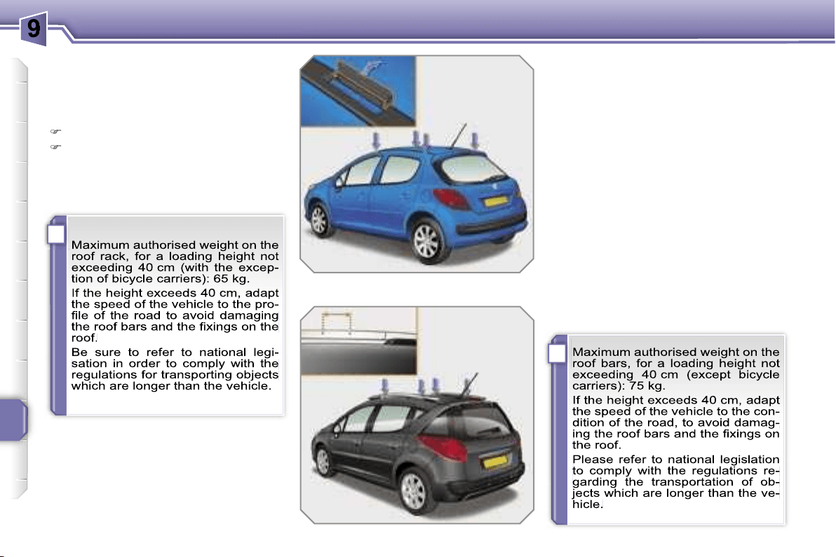
i
i
PRACTICAL INFORMATION
156
FITTING ROOF
BARS (SALOON)
When fitting transverse roof bars, use
the four quick-fit fixings provided for this
purpose:
lift the concealing flaps,
adjust the roof bar quick-fit fixings.
FITTING ROOF BARS (SW)
Consult a PEUGEOT dealer for the in-
stallation of longitudinal roof bars.
When fitting transverse roof bars, en-
sure that they are positioned correctly
as shown by marks on the longitudinal
roof bars.
Use accessories recommended by
PEUGEOT and follow the accessory
manufacturer’s fitting instructions.
In order to place a load on the roof, your
vehicle must be fitted with longitudinal
roof bars with transverse roof bars fitted
on top of these.
Lashing the straps through the ends of
the longitudinal roof bars is prohibited.
The longitudinal roof bars cannot be re-
moved.
!
i
PRACTICAL INFORMATION
157
ACCESSORIES
You can obtain a wide range of ac-
cessories and original parts from the
PEUGEOT network.
These accessories and parts have been
tested and approved for reliability and
safety.
They are all adapted to your vehicle and
benefit from PEUGEOT’s recommenda-
tion and warranty.
The product range offered by PEUGEOT
Accessories is structured around 5 cat-
egories: PROTECTION - TOURING -
IN-CAR TECHNOLOGY - STYLING -
UNIVERSAL.
"Protection":
"Touring":
"In-car technology":
"Styling":
"Universal":
You can obtain "Van" conversion kits to
transform a private vehicle into a van.
*
To prevent the mat from becoming
caught under the pedals:
- ensure that the mat is positioned and
secured correctly,
- never fit one mat on top of another.
anti-theft alarm, window en-
graving, wheel locks, first aid
kit, warning triangle, safety
jacket, stolen vehicle tracking
system, snow chains.
mats*, boot tray, luggage net,
dog guard, fixed coat hook on
head restraint, aluminium or
PVC door sills.
For leisure pursuits: roof bars,
bicycle carrier on towbar, bi-
cycle carrier on roof bars, ski
carrier, roof box, booster seats
and child seats, audio/telephone con-
sole, side blinds and rear blind, front
centre armrest, CD storage, under shelf
storage.
Trailer towbar which must be fitted by
the PEUGEOT network.
audio systems, telephone,
amplifiers, satellite naviga-
tion systems, hands-free kit,
CD changer, speakers, DVD
player, connection kit for MP3
player or portable CD player,
rear parking assistance.
seat covers compatible with
side air bags, aluminium
gear lever knob, fog lamps,
door deflectors, spoiler, styl-
ing strips, alloy wheels, trims,
sport exhaust, chromed mirror
casings.
screenwash, interior and exte-
rior maintenance and cleaning
products.

10
158
MODELS:
ENGINES AND GEARBOXES
Model codes:
KFV-C
KFU-C
KFU-C/P
8FS-C
PETROL ENGINES
1.4 litre
75 bhp
1.4 litre 16V
90 bhp*
1.4 litre 16V
95 bhp
Cubic capacity (cm
3
)
1 360
1 360
1 397
Bore x stroke (mm)
75 x 77
75 x 77
75 x 77
Maximum power: EU standard (kW)
54
65
70
Maximum power engine speed (rpm)
5 400
5 250
6 000
Maximum torque: EU standard (Nm)
118
133
135
Maximum torque engine speed (rpm)
3 300
3 250
3 500
Fuel
Unleaded
Unleaded
Unleaded
Catalytic converter
Yes
Yes
Yes
GEARBOX
Manual
(5-speed)
Manual
(5-speed)
"2 Tronic"
(5-speed)
Manual
(5-speed)
OIL CAPACITIES (in litres)
Engine (with cartridge replacement)
3.25
3.25
3.25
4.25
Gearbox - Final drive
1.9
1.9
-
1.9
* Not available on SW.
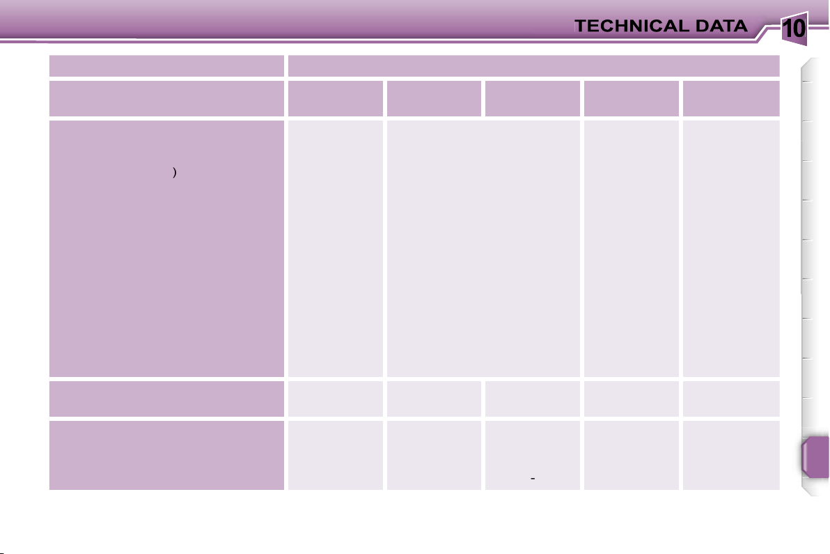
10
159
MODELS:
ENGINES AND GEARBOXES
Model codes:
NFU-C
5FW-C
5FW-F
5FX-C
5FY-C
PETROL ENGINES
1.6 litre 16V
110 bhp*
1.6 litre 16V
120 bhp
1.6 litre THP
16V 150 bhp*
1.6 litre THP
16V 175 bhp
Cubic capacity (cm
3
)
1 587
1 598
1 598
1 598
Bore x stroke (mm)
78.5 x 82
77 x 85.8
77 x 85.8
77 x 85.8
Maximum power: EU standard (kW)
80
88
110
128
Maximum power engine speed (rpm)
5 800
6 000
5 800
6 000
Maximum torque: EU standard (Nm)
147
160
240
240
Maximum torque engine speed (rpm)
4 000
4 250
1 400
1 600
Fuel
Unleaded
Unleaded
Unleaded
Unleaded**
Catalytic converter
Yes
Yes
Yes
Yes
GEARBOX
Manual
(5-speed)
Manual
(5-speed)
Auto
(4-speed)
Manual
(5-speed)
Manual
(5-speed)
OIL CAPACITIES (in litres)
Engine (with cartridge replacement)
3.25
4.25
4.25
4.25
4.25
Gearbox - Final drive
1.9
1.9
-
1.9
1.9
* Not available on SW.
** PEUGEOT recommends the use of RON98 unleaded petrol to guarantee optimum performance of the engine.
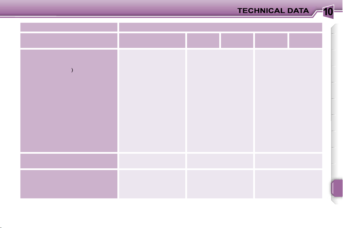
10
167
MODELS:
ENGINES AND GEARBOXES
Model codes:
8HZ-C
9HX-C
9HV-C
9HY-C
9HZ-C
DIESEL ENGINES
1.4 litre Turbo HDI
70 bhp*
1.6 litre Turbo HDI 16V
90 bhp
1.6 litre Turbo HDI 16V
110 bhp
Cubic capacity (cm
3
)
1 398
1 560
1 560
Bore x stroke (mm)
73.7 x 82
75 x 88.3
75 x 88.3
Maximum power: EU standard (kW)
50
66
80
Maximum power engine speed (rpm)
4 000
4 000
4 000
Maximum torque: EU standard (Nm)
160
215
240
Maximum torque engine speed (rpm)
2 000
1 750
1 750
Fuel
Diesel
Diesel
Diesel
Catalytic converter
Yes
Yes
Yes
Particle emission filter
No
No
Yes
No
Yes
GEARBOX
Manual
(5-speed)
Manual
(5-speed)
Manual
(5-speed)
OIL CAPACITIES (in litres)
Engine (with cartridge replacement)
3.75
3.25
3.25
Gearbox - Final drive
1.9
1.9
1.9
* Not available on SW.
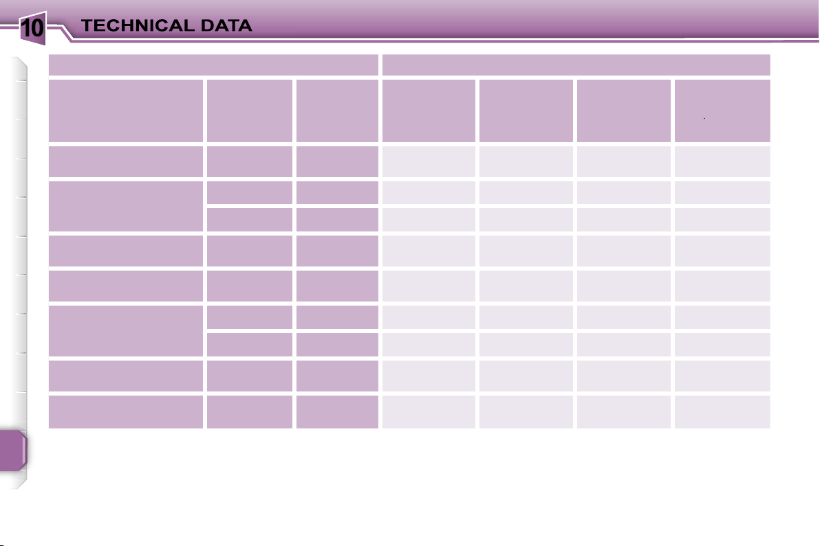
10
160
SALOON CONSUMPTION
In accordance with EC Directive 80/1268 (as amended)
Petrol engines
Gearbox
Model
codes
WC... WA...
WG... WM...
Urban driving
mpg (litres/
100 km)
Inter-urban
driving mpg
(litres/
100 km)
Mixed driving
mpg (litres/
100 km)
Emission of
CO
2
by mass
(g/km)
2
2
1.4 litre 75 bhp
Manual
KFV-C
33.6 (8.4)
56.5 (5.0)
44.8 (6.3)
150
1.4 litre 16V 90 bhp
Manual
KFU-C
33.2 (8.5)
54.3 (5.2)
44.1 (6.4)
152
"2 Tronic"
KFU-C/P
35.8 (7.9)
54.3 (5.2)
45.6 (6.2)
146
1.4 litre 16V 95 bhp
Manual
8FS-C
34.9 (8.1)
56.5 (5.0)
46.3 (6.1)
145
1.6 litre 16V 110 bhp
Manual
NFU-C
30.4 (9.3)
50.4 (5.6)
40.4 (7.0)
166
1.6 litre 16V 120 bhp
Manual
5FW-C
33.6 (8.4)
60.1 (4.8)
46.3 (6.1)
145
Auto.
5FW-F
28.8 (9.8)
51.4 (5.5)
40.4 (7.0)
167
1.6 litre THP 16V
150 bhp
Manual
5FX-C
30.4 (9.3)
50.4 (5.6)
40.4 (7.0)
166
1.6 litre THP 16V
175 bhp
Manual
5FY-C
28.5 (9.9)
49.6 (5.7)
39.2 (7.2)
171
The consumption figures shown here correspond to the values communicated at the time of printing.
These consumption values were established in accordance with EC Directive 80/1268 (as amended). They may vary depend-
ing on the style of driving, traffic conditions, weather conditions, the load in the vehicle, the maintenance of the vehicle and
the use of the accessories.
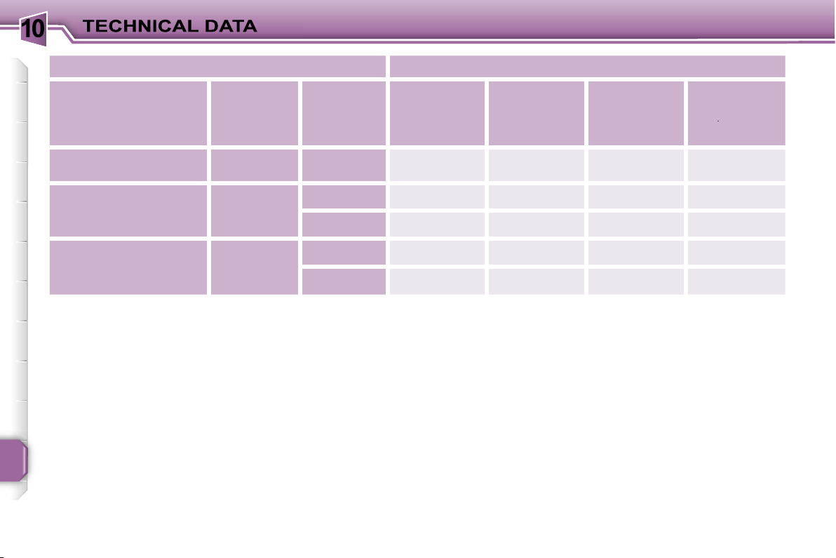
10
168
SALOON CONSUMPTION
In accordance with EC Directive 80/1268 (as amended)
Diesel engines
Gearbox
Model
codes
WC... WA...
WG...
Urban driving
mpg (litres/
100 km)
Inter-urban
driving mpg
(litres/
100 km)
Mixed driving
mpg (litres/
100 km)
Emission of
CO
2
by mass
(g/km)
2
2
1.4 litre Turbo HDI
70 bhp
Manual
8HZ-C
48.7 (5.8)
74.3 (3.8)
62.8 (4.5)
120
1.6 litre Turbo HDI 16V
90 bhp
Manual
9HX-C
48.7 (5.8)
74.3 (3.8)
62.8 (4.5)
120
9HV-C
47.1 (6.0)
68.9 (4.1)
58.8 (4.8)
126
1.6 litre Turbo HDI 16V
110 bhp
Manual
9HY-C
45.6 (6.2)
68.9 (4.1)
57.6 (4.9)
129
9HZ-C
47.1 (6.0)
68.9 (4.1)
58.8 (4.8)
126
The consumption figures shown here correspond to the values communicated at the time of printing.
These consumption values were established in accordance with EC Directive 80/1268 (as amended). They may vary depend-
ing on the style of driving, traffic conditions, weather conditions, the load in the vehicle, the maintenance of the vehicle and
the use of the accessories.
10
161
SW CONSUMPTION
In accordance with EC Directive 80/1268 (as amended)
Petrol engines
Gearbox
Model
codes WE...
Urban driving
mpg (litres/
100 km)
Inter-urban
driving mpg
(litres/
100 km)
Mixed driving
mpg (litres/
100 km)
Emission of
CO
2
by mass
(g/km)
2
2
1.4 litre 75 bhp
Manual
KFV-C
8,8
5,3
6,5
155
1.4 litre 16V 95 bhp
Manual
8FS-C
8,2
5,2
6,3
150
1.6 litre 16V 120 bhp
Manual
5FW-C
8,6
5,0
6,3
150
Auto.
5FW-F
9,8
5,5
7,0
167
1.6 litre THP 16V
175 bhp
Manual
5FY-C
10,2
5,9
7,4
175
The consumption figures shown here correspond to the values communicated at the time of printing.
These consumption values were established in accordance with EC Directive 80/1268 (as amended). They may vary depend-
ing on the style of driving, traffic conditions, weather conditions, the load in the vehicle, the maintenance of the vehicle and
the use of the accessories.
10
169
SW CONSUMPTION
In accordance with EC Directive 80/1268 (as amended)
Diesel engines
Gearbox
Model
codes WE...
Urban driving
mpg (litres/
100 km)
Inter-urban
driving mpg
(litres/
100 km)
Mixed driving
mpg (litres/
100 km)
Emission of
CO
2
by mass
(g/km)
2
2
1.6 litre Turbo HDI 16V
90 bhp
Manual
9HX-C
48.7 (5.8)
70.7 (4.0)
61.6 (4.6)
123
9HV-C
46.3 (6.1)
64.2 (4.4)
56.5 (5.0)
131
1.6 litre Turbo HDI 16V
110 bhp
Manual
9HY-C
-
-
-
-
9HZ-C
46.3 (6.1)
64.2 (4.4)
56.5 (5.0)
131
The consumption figures shown here correspond to the values communicated at the time of printing.
These consumption values were established in accordance with EC Directive 80/1268 (as amended). They may vary depend-
ing on the style of driving, traffic conditions, weather conditions, the load in the vehicle, the maintenance of the vehicle and
the use of the accessories.
10
162
SALOON WEIGHTS AND TOWED LOADS (in kg)
Petrol engines
1.4 litre 75 bhp
1.4 litre 16V 90 bhp
Gearbox
Manual
Manual
"2 Tronic"
Model codes: WC... WA... WG...
KFV-C
KFU-C
KFU-C/P
- Kerb weight
1 300 - 1 288 - 1 232
1 224 - 1 214
1 241 - 1 231
- Payload
320 - 292 - 338
416 - 406
409 - 399
- Gross vehicle weight (GVW)
1 620 - 1 580 - 1 570
1 640 - 1 620
1 650 - 1 630
- Gross train weight (GTW)
on a 12 % gradient
2 400
2 580
2 580
- Braked trailer (within GTW limit)
on a 10 % or 12 % gradient
780 - 820 - 830
940 - 960
930 - 950
on an 8 % gradient
830 - 870
980 - 1 000
950 - 970
- Braked trailer* (with load transfer within GTW limit)
950
1 150
1 150
- Unbraked trailer
600 - 600 - 590
600
600
- Recommended nose weight
38 - 38 - 46
46
46
* The weight of the braked trailer may be increased, within the GTW limit, on condition that the GVW of the towing vehicle is reduced
by the same amount; warning, towing using a lightly loaded towing vehicle may adversely affect its roadholding performance.
The GTW and towed load values indicated apply up to a maximum altitude of 1 000 metres; the towed load mentioned must be
reduced by 10 % for each additional 1 000 metres of altitude.
The speed of a towing vehicle must not exceed 60 mph (100 km/h) (comply with the legislation in force in your country).
High exterior temperatures may result in a reduction in the performance of the vehicle in order to protect the engine; when the
exterior temperature is higher than 37 °C, limit the weight towed.

10
163
SALOON WEIGHTS AND TOWED LOADS (in kg)
Petrol engines
1.4 litre 16V 95 bhp
1.6 litre 16V 110 bhp
Gearbox
Manual
Manual
Model codes: WC... WA... WG...
8FS-C
NFU-C
- Kerb weight
1 253 - 1 240
1 300 - 1 288
- Payload
387 - 400
380 - 382
- Gross vehicle weight (GVW)
1 640
1 680 - 1 670
- Gross train weight (GTW)
on a 12 % gradient
2 580
2 630
- Braked trailer (within GTW limit)
on a 10 % or 12 % gradient
940
950 - 960
on an 8 % gradient
-
1 000 - 1 010
- Braked trailer* (with load transfer within GTW limit)
1 150
1 150
- Unbraked trailer
600
600
- Recommended nose weight
46
46
* The weight of the braked trailer may be increased, within the GTW limit, on condition that the GVW of the towing vehicle is reduced
by the same amount; warning, towing using a lightly loaded towing vehicle may adversely affect its roadholding performance.
The GTW and towed load values indicated apply up to a maximum altitude of 1 000 metres; the towed load mentioned must be
reduced by 10 % for each additional 1 000 metres of altitude.
The speed of a towing vehicle must not exceed 60 mph (100 km/h) (comply with the legislation in force in your country).
High exterior temperatures may result in a reduction in the performance of the vehicle in order to protect the engine; when the exterior
temperature is higher than 37 °C, limit the weight towed.

10
164
SALOON WEIGHTS AND TOWED LOADS (in kg)
Petrol engines
1.6 litre 16V 120 bhp
1.6 litre THP 16V
150 bhp
150 bhp
1.6 litre THP 16V
175 bhp
175 bhp
Gearbox
Manual
Auto
Manual
Manual
Model codes: WC... WA... WM...
5FW-C
5FW-F
5FX-C
5FY-C
- Kerb weight
1 275
1 321 - 1 312
1 370 - 1 356
1 325
- Payload
375 - 365
374 - 366
340 - 344
275
- Gross vehicle weight (GVW)
1 650 - 1 640
1 695 - 1 678
1 710 - 1 700
1 600
- Gross train weight (GTW)
on a 12 % gradient
2 600
2 645 - 2 638
2 640
2 500
- Braked trailer (within GTW limit)
on a 10 % or 12 % gradient
950 - 960
950 - 960
930
900
on an 8 % gradient
1 000 - 1 010
1 000 - 1 010
1 000
1 000
-
Braked trailer* (with load transfer within GTW limit)
1 150
1 150
1 150
1 080
- Unbraked trailer
600
600
600
600
- Recommended nose weight
46
46
46
44
* The weight of the braked trailer may be increased, within the GTW limit, on condition that the GVW of the towing vehicle
is reduced by the same amount; warning, towing using a lightly loaded towing vehicle may adversely affect its roadholding
performance.
The GTW and towed load values indicated apply up to a maximum altitude of 1 000 metres; the towed load mentioned must
be reduced by 10 % for each additional 1 000 metres of altitude.
The speed of a towing vehicle must not exceed 60 mph (100 km/h) (comply with the legislation in force in your country).
High exterior temperatures may result in a reduction in the performance of the vehicle in order to protect the engine; when
the exterior temperature is higher than 37 °C, limit the weight towed.

10
170
SALOON WEIGHTS AND TOWED LOADS (in kg)
Diesel engines
1.4 litre Turbo HDI
70 bhp
70 bhp
1.6 litre Turbo HDI 16V
90 bhp
90 bhp
90 bhp
1.6 litre Turbo HDI 16V
110 bhp
110 bhp
110 bhp
Gearbox
Manual
Manual
Manual
Model codes: WC... WA... WG...
8HZ-C
9HX-C
9HV-C
9HY-C
9HZ-C
- Kerb weight
1 261 - 1 251 - 1 269
1 280 - 1 272 - 1 290
1 328 - 1 319 - 1 358
- Payload
399 - 369 - 341
420 - 408 - 340
382 - 391 - 323
- Gross vehicle weight (GVW)
1 660 - 1 620 - 1 610
1 700 - 1 680 - 1 630
1 710 - 1 710 - 1 681
- Gross train weight (GTW)
on a 12 % gradient
2 600
2 650
2 690
- Braked trailer (within GTW limit)
on a 10 % or 12 % gradient
940 - 980 - 990
950 - 970 - 1 020
980
on an 8 % gradient
940 - 980
980 - 1 000
1 030
-
Braked trailer* (with load transfer within GTW limit)
1 150
1 150
1 150
- Unbraked trailer
600
600
600
- Recommended nose weight
46
46
46
* The weight of the braked trailer may be increased, within the GTW limit, on condition that the GVW of the towing vehicle is reduced
by the same amount; warning, towing using a lightly loaded towing vehicle may adversely affect its roadholding performance.
The GTW and towed load values indicated apply up to a maximum altitude of 1 000 metres; the towed load mentioned must be
reduced by 10 % for each additional 1 000 metres of altitude.
The speed of a towing vehicle must not exceed 60 mph (100 km/h) (comply with the legislation in force in your country).
High exterior temperatures may result in a reduction in the performance of the vehicle in order to protect the engine; when the
exterior temperature is higher than 37 °C, limit the weight towed.

10
165
SW WEIGHTS AND TOWED LOADS (in kg)
Petrol engines
1.4 litre 75 bhp
1.4 litre 16V 95 bhp
Gearbox
Manual
Manual
Model codes: WE...
KFV-C
8FS-C
- Kerb weight
1 271
1 290
- Payload
371
401
- Gross vehicle weight (GVW)
1 642
1 691
- Gross train weight (GTW)
on a 12 % gradient
2 422
2 591
- Braked trailer (within GTW limit)
on a 10 % or 12 % gradient
780
900
on an 8 % gradient
-
-
-
Braked trailer* (with load transfer within GTW limit)
1 045
1 150
- Unbraked trailer
600
600
- Recommended nose weight
42
46
* The weight of the braked trailer may be increased, within the GTW limit, on condition that the GVW of the towing vehicle is reduced
by the same amount; warning, towing using a lightly loaded towing vehicle may adversely affect its roadholding performance.
The GTW and towed load values indicated apply up to a maximum altitude of 1 000 metres; the towed load mentioned must be
reduced by 10 % for each additional 1 000 metres of altitude.
The speed of a towing vehicle must not exceed 60 mph (100 km/h) (comply with the legislation in force in your country).
High exterior temperatures may result in a reduction in the performance of the vehicle in order to protect the engine; when the
exterior temperature is higher than 37 °C, limit the weight towed.
10
166
SW WEIGHTS AND TOWED LOADS (in kg)
Petrol engines
1.6 litre 16V 120 bhp
1.6 litre THP 16V 175 bhp
Gearbox
Manual
Auto
Manual
Model codes: WE...
5FW-C
5FW-F
5FY-C
- Kerb weight
1 302
1 335
1 428
- Payload
403
402
340
- Gross vehicle weight (GVW)
1 705
1 737
1 768
- Gross train weight (GTW)
on a 12 % gradient
2 605
2 687
2 718
- Braked trailer (within GTW limit)
on a 10 % or 12 % gradient
900
950
950
on an 8 % gradient
-
-
-
-
Braked trailer* (with load transfer within GTW limit)
1 150
1 150
1 150
- Unbraked trailer
600
600
600
- Recommended nose weight
46
46
46
* The weight of the braked trailer may be increased, within the GTW limit, on condition that the GVW of the towing vehicle is reduced
by the same amount; warning, towing using a lightly loaded towing vehicle may adversely affect its roadholding performance.
The GTW and towed load values indicated apply up to a maximum altitude of 1 000 metres; the towed load mentioned must be
reduced by 10 % for each additional 1 000 metres of altitude.
The speed of a towing vehicle must not exceed 60 mph (100 km/h) (comply with the legislation in force in your country).
High exterior temperatures may result in a reduction in the performance of the vehicle in order to protect the engine; when the
exterior temperature is higher than 37 °C, limit the weight towed.
10
171
SW WEIGHTS AND TOWED LOADS (in kg)
Diesel engines
1.6 litre Turbo HDI 16V 90 ch
1.6 litre Turbo HDI 16V 110 ch
Gearbox
Manuelle
Manuelle
Model codes: WE...
9HX-C
9HV-C
9HY-C
9HZ-C
- Kerb weight
1 339
1 350
- Payload
402
408
- Gross vehicle weight (GVW)
1 741
1 758
- Gross train weight (GTW)
on a 12 % gradient
2 691
2 708
- Braked trailer (within GTW limit)
on a 10 % or 12 % gradient
950
950
on an 8 % gradient
-
-
-
Braked trailer* (with load transfer within GTW limit)
1 150
1 150
- Unbraked trailer
600
600
- Recommended nose weight
46
46
* The weight of the braked trailer may be increased, within the GTW limit, on condition that the GVW of the towing vehicle is reduced
by the same amount; warning, towing using a lightly loaded towing vehicle may adversely affect its roadholding performance.
The GTW and towed load values indicated apply up to a maximum altitude of 1 000 metres; the towed load mentioned must be
reduced by 10 % for each additional 1 000 metres of altitude.
The speed of a towing vehicle must not exceed 60 mph (100 km/h) (comply with the legislation in force in your country).
High exterior temperatures may result in a reduction in the performance of the vehicle in order to protect the engine; when the
exterior temperature is higher than 37 °C, limit the weight towed.
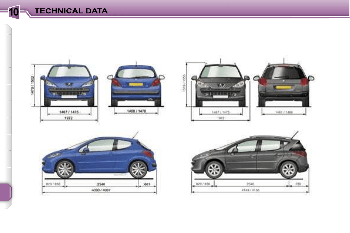
10
172
DIMENSIONS (in mm)
207 saloon (3 and 5 door versions)/207 GTi 207 SW
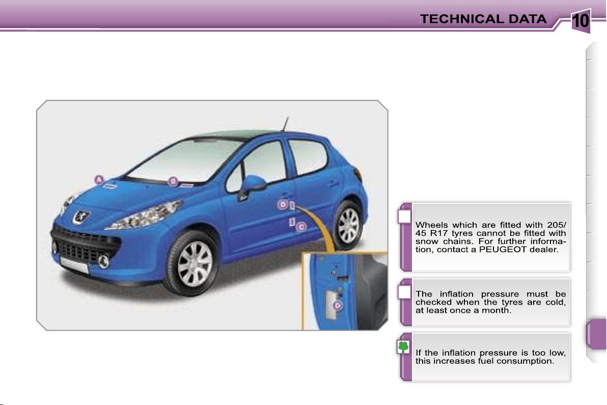
10
!
i
173
IDENTIFICATION FEATURES
Various visible marking elements for
the identification and tracking of your
vehicle.
A. Chassis number under
the bonnet.
This number is etched on the bodywork
near the passenger compartment filter.
B. Chassis number on the fascia.
This number is indicated on a gummed
label which is visible through the wind-
screen.
C. Chassis number on the chassis.
This number is indicated on a self-
destroying label affixed to the centre pil-
lar, near the driver’s door striker.
D. Manufacturer’s label.
This label is affixed to the edge of the
door on the driver’s side.
It bears the following information:
- the wheel rim and tyre sizes,
- the brands of tyre recommended by
the manufacturer,
- the associated inflation pressures,
- the paint colour reference.
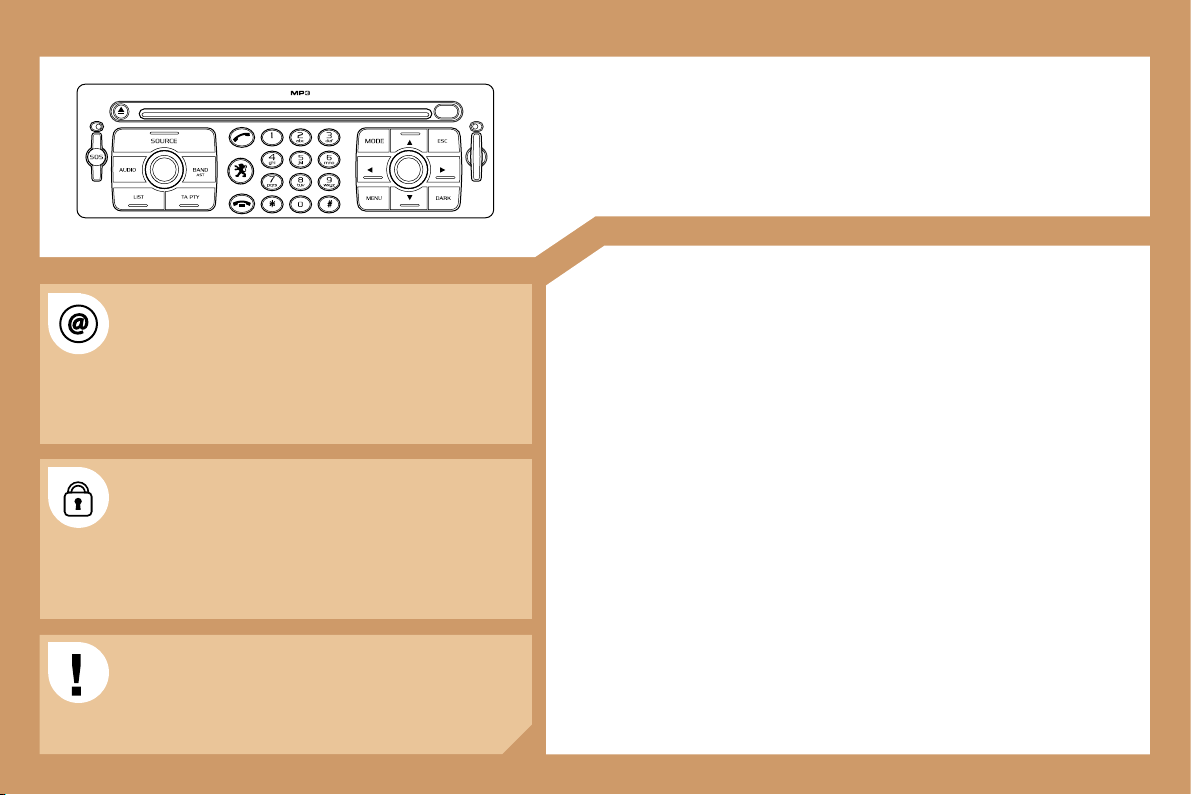
175
RT3
AUDIO EQUIPMENT/TELEPONE/GPS
CONTENTS
• 01 First steps pg. 178
• 02 General menu pg. 179
• 03 GPS pg. 180
• 04 Audio pg. 187
• 05 Telephone pg. 189
• 06 Control short-cuts pg. 192
• 07 Configuration pg. 194
• 08 Display flow chart pg. 196
• Frequently asked questions pg. 209
The INFOTEC website provides additional, animated
information on the RT3. It can be consulted at the
following address:
http://public.infotec.peugeot.com.
Registering on the site allows access to the vehicle
handbook documentation, which can be consulted free
of charge.
The RT3 GPS audio/telephone is coded in such a
way that it will only operate in your vehicle. If it is to be
installed in another vehicle, contact your PEUGEOT
dealer for configuration of the system.
For safety reasons, the driver must carry out
operations which require prolonged attention while the
vehicle is stationary.
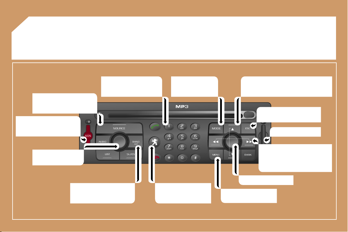
176
01 FIRST STEPS
Selection of the source: radio,
CD, CD changer and auxiliary
(AUX).
Long press on the SOS button:
emergency call.
On/Off.
Volume adjustment.
Selection of the FM1, FM2,
FMast, AM wavebands.
Keypad for entering
descriptions by means of
successive presses.
Access to the "PEUGEOT"
services menu.
Displaying of the general
menu.
SIM card flap.
Cancellation of the current
operation.
- Selection of a lower/higher frequency.
- Selection of the previous/next CD.
- Selection of the previous/next MP3
directory.
- Automatic search for a lower/
higher frequency.
- Selection of the previous/next
track on CD or MP3.
Selection and confirmation.
Selection of the
screen display mode.
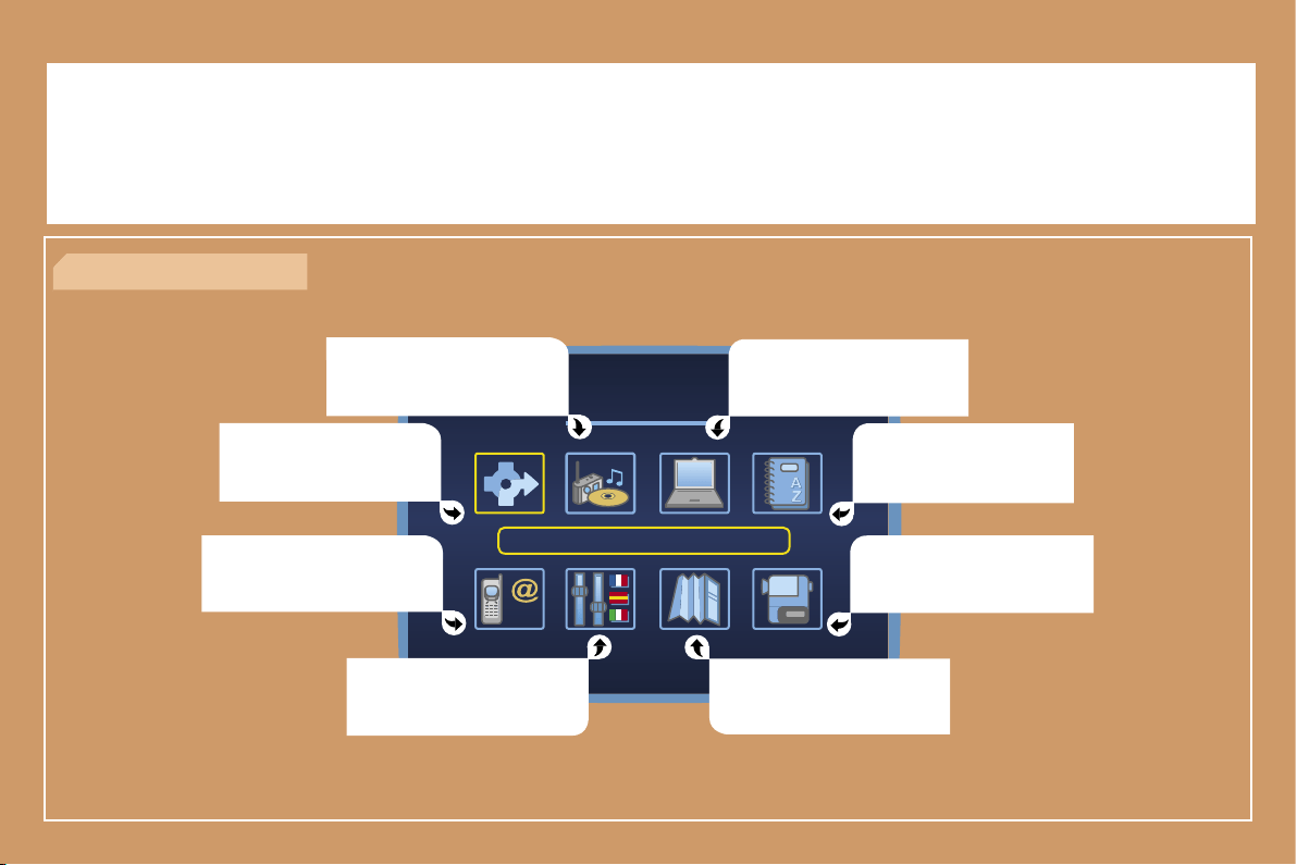
177
02 GENERAL MENU
AUDIO FUNCTIONS: radio,
options.
NAVIGATION: GPS, traffic
information, options.
> COLOUR DISPLAY DT
TRIP COMPUTER: speed,
consumption, distance.
DIRECTORY: telephone and
GPS.
VIDEO: activation, parameters.
MAP: GPS, details, orientation.
CONFIGURATION: vehicle
parameters, display, time,
languages.
TELEPHONE functions:
services, telephone functions,
SMS.
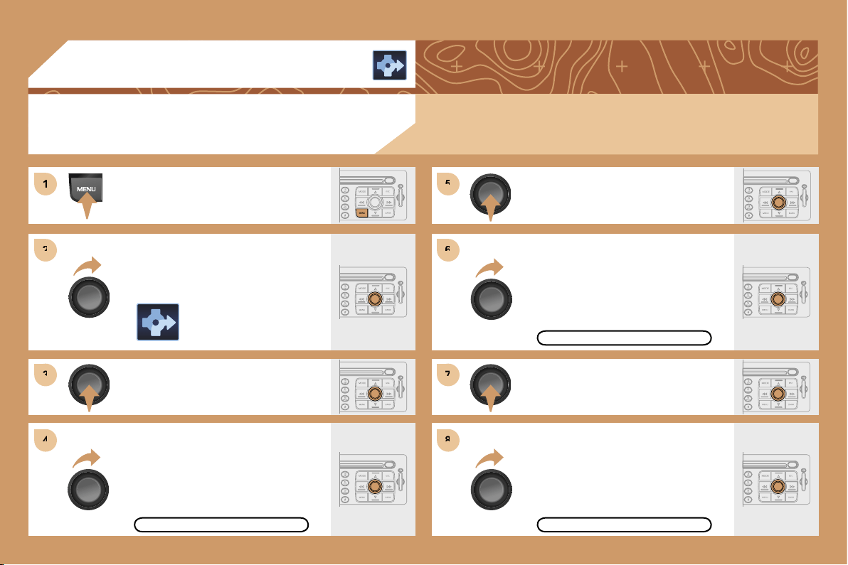
178
1
1
2
2
3
3
5
5
7
7
4
4
6
6
8
8
03 GPS
ENTERING AN ADDRESS AND
ACTIVATING GUIDANCE
Press the MENU button.
Turn the dial and select the
NAVIGATION function.
Press the dial to confirm the selection.
Turn the dial and select the
DESTINATION CHOICE function.
Press the dial to confirm the selection.
Press the dial to confirm the selection.
Turn the dial and select the
ENTER AN ADDRESS function.
Turn the dial and select the TOWN
function.
TOWN
ENTER AN ADDRESS
The navigation CD ROM:
Insert the navigation CD ROM in the drive on the control panel and leave it
there in order to use the Navigation functions.
DESTINATION CHOICE
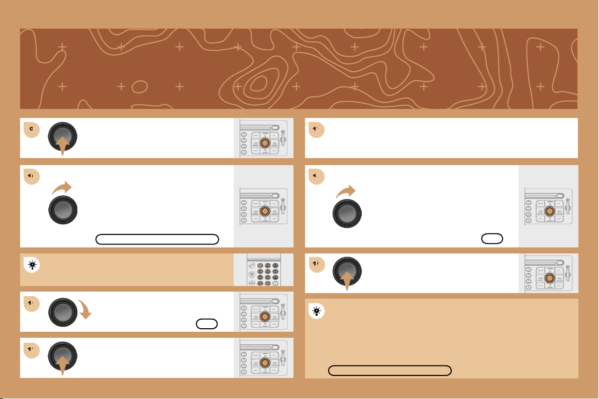
179
9
9
11
11
12
12
13
13
15
15
10
10
14
14
Press the dial to confirm the selection.
Turn the dial and select the letters of
the town one by one confirming each
time by pressing the dial.
Turn the dial and select the OK
function.
Press the dial to confirm the selection.
Use the alphanumeric keypad to enter the letters and
digits and * to correct.
Press the dial to confirm the selection.
Select the OK function on the
ENTER AN ADDRESS page.
Repeat steps 8 to 12 for the ROAD and N
o
functions.
PARIS
OK
OK
Select the STORE function to record the address entered in a
directory record and press the dial to confirm the selection.
STORE
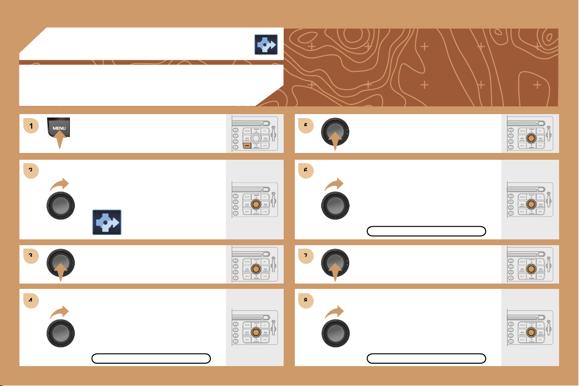
180
1
1
2
2
3
3
4
4
5
5
6
6
7
7
8
8
03 GPS
GUIDANCE OPTIONS
Press the MENU button.
Turn the dial and select the
NAVIGATION function.
Press the dial to confirm the selection.
Turn the dial and select the
GUIDANCE OPTIONS function.
Press the dial to confirm the selection.
Press the dial to confirm the selection.
Turn the dial and select the
DEFINE CALCULATION CRITERIA
function.
Turn the dial and select, for example,
the FASTEST ROUTE function.
GUIDANCE OPTIONS
FASTEST ROUTE
DEFINE CALCULATION CRITERIA
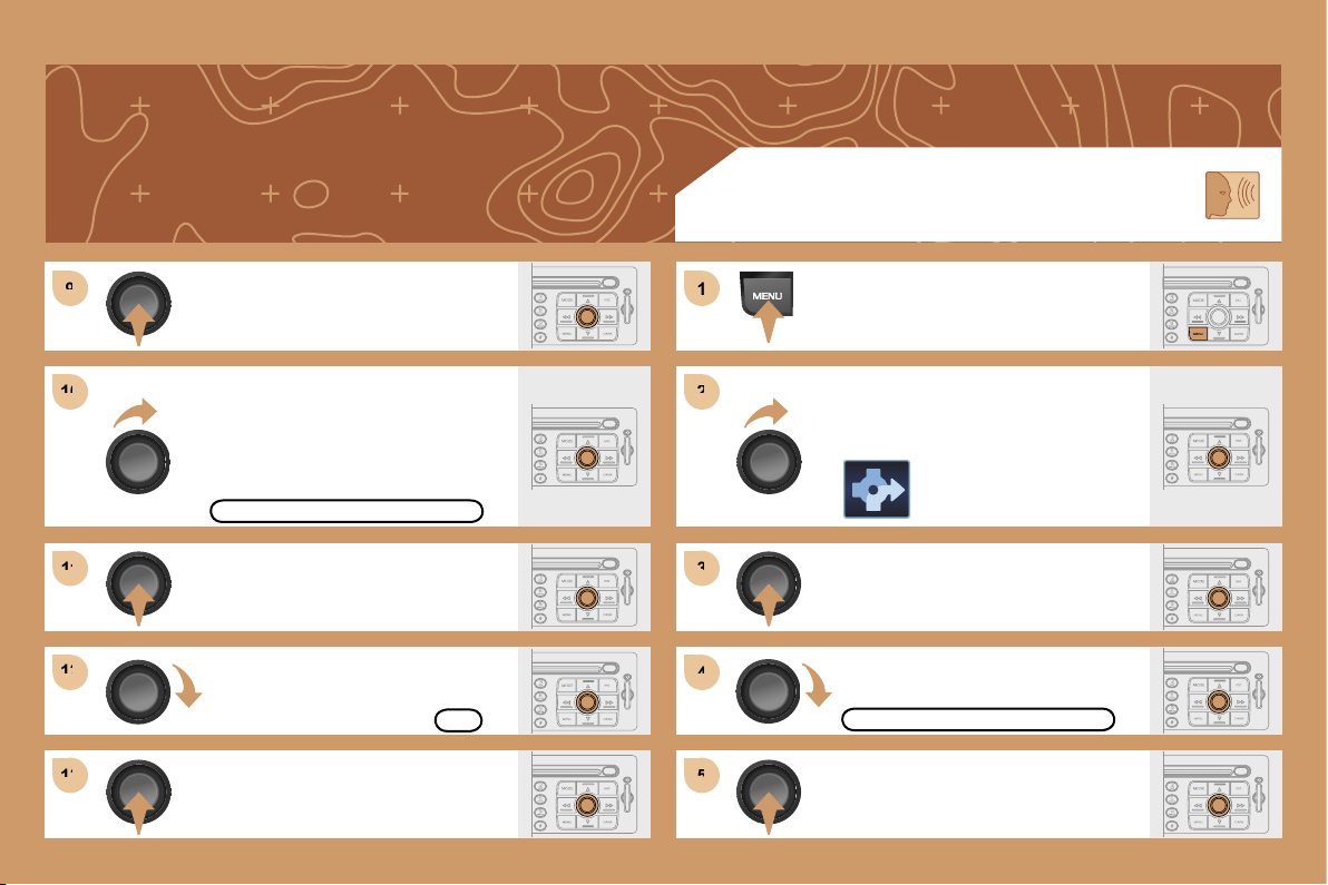
181
9
9
10
10
11
11
12
12
13
13
1
1
2
2
3
3
4
4
5
5
Press the dial to confirm the selection.
Press the dial to confirm the selection.
Turn the dial and select the
WITH TOLLS function if it is
not ticked.
SPEECH SYNTHESIS
Press the MENU button.
Turn the dial and select the
NAVIGATION function.
Press the dial to confirm the selection.
Turn the dial and select the
GUIDANCE OPTIONS function.
WITH TOLLS
GUIDANCE OPTIONS
Press the dial to confirm the selection.
Turn the dial and select the OK
function.
Press the dial to confirm the selection.
OK
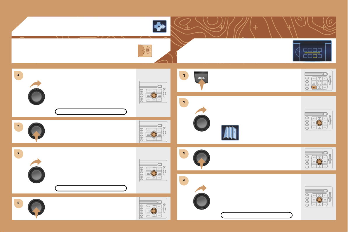
182
6
6
7
7
8
8
9
9
1
1
2
2
3
3
4
4
Press the dial to confirm the selection.
Turn the dial and select the
ADJUST SPEECH SYNTHESIS
function.
Turn the dial and select the ACTIVATE
function.
Press the dial to confirm the function.
03 GPS
SPEECH SYNTHESIS
ADJUST SPEECH SYNTHESIS
ACTIVATE
Press the MENU button.
Turn the dial and select the MAP
function.
Press the dial to confirm the selection.
Turn the dial and select the MAP
DETAILS function.
Permits selection of the services
which can be seen on the map (hotels,
restaurants...).
ACTIONS ON THE MAP
MAP DETAILS
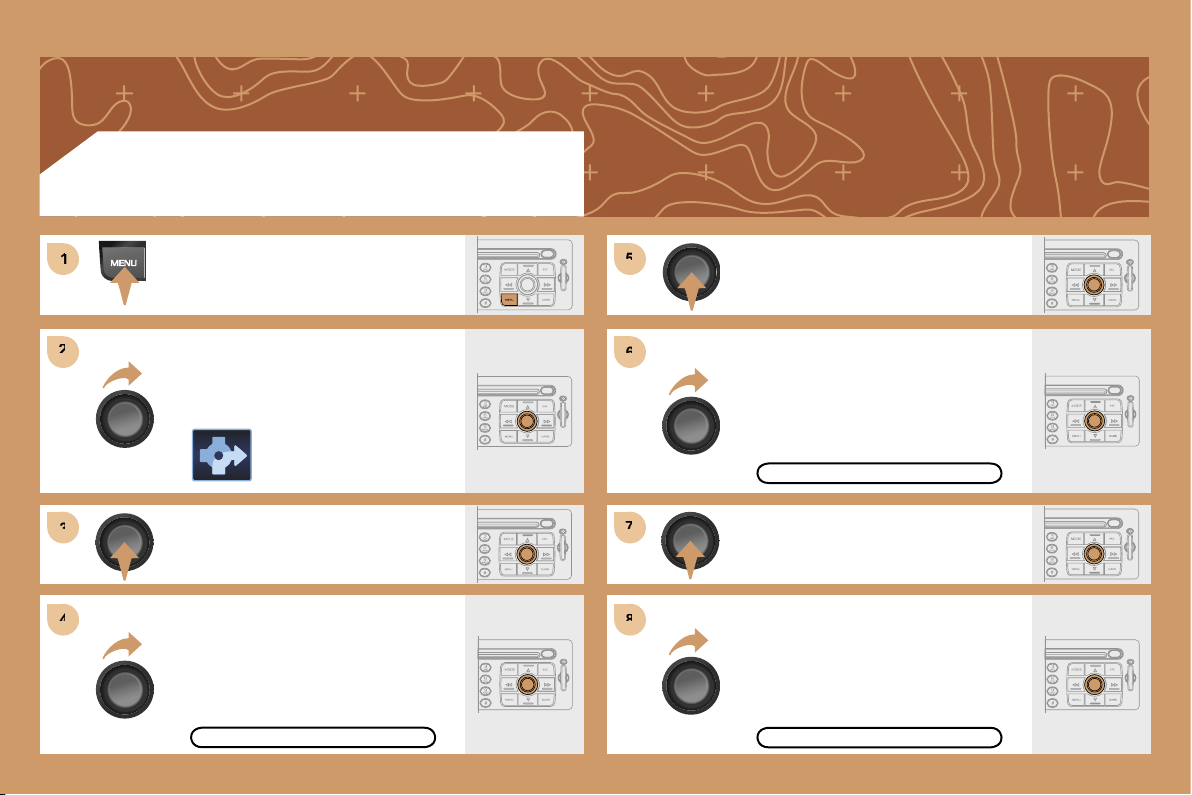
183
1
1
2
2
3
3
4
4
5
5
6
6
7
7
8
8
ACTIVATING THE ROUTE FILTER
Press the MENU button.
Turn the dial and select the
NAVIGATION function.
Press the dial to confirm the selection.
Turn the dial and select the TMC
TRAFFIC INFORMATION function.
TMC TRAFFIC INFORMATION
Press the dial to confirm the selection.
Turn the dial and select the
FILTER THE TMC INFORMATION
function.
FILTER TMC INFORMATION
Press the dial to confirm the selection.
Turn the dial and select the
ACTIVATE ROUTE FILTER function.
ACTIVATE ROUTE FILTER
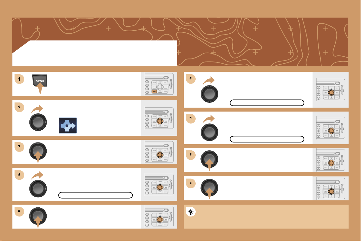
184
1
1
2
2
3
3
4
4
6
6
5
5
7
7
8
8
9
9
ADDING A STAGE
Press the MENU button.
Turn the dial and select the
NAVIGATION function.
Press the dial to confirm the selection.
Turn the dial and select the STAGES
AND ROUTE function.
STAGES AND ROUTE
Turn the dial and select the ADD A
STAGE function.
Press the dial to confirm the selection.
ADD A STAGE
Press the dial to confirm the selection.
Enter an address (see GPS section)
or select SERVICE CHOICE
(restaurants, hotel...).
SERVICE CHOICE
Press the dial to confirm the selection.
Press the dial to confirm the order of
the stages.
Once the stage has been reached, guidance is redirected towards the
destination.
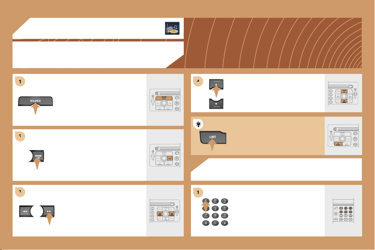
185
1
2
2
3
3
4
4
1
1
04 AUDIO
RADIO
SELECTING A STATION
RADIO
STORING A STATION
Press the SOURCE button several
times in succession and select the
RADIO.
Press the BAND AST button to select a
waveband: FM1, FM2, FMast, AM.
Briefly press one of the buttons to carry
out an automatic search of the radio
stations.
Press one of the buttons on the
alphanumeric keypad for more than
2 seconds to store the frequency
of the current station.
Press one of the buttons to carry out a
manual search of the radio stations.
Press the LIST button to display
the list of stations received locally.
To update this list, press for more than
two seconds.
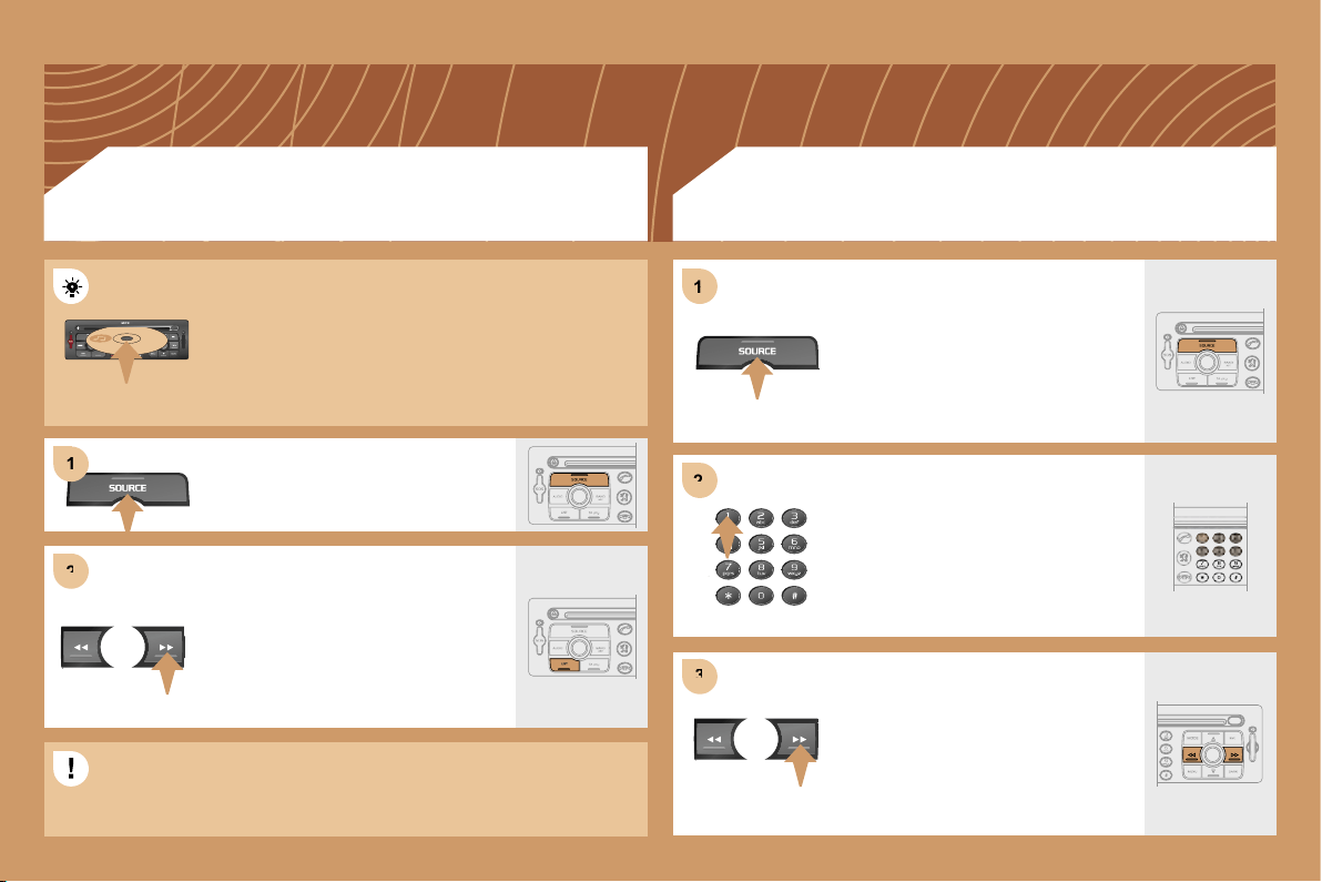
186
2
2
1
1
2
2
3
3
1
1
CD
PLAYING A CD OR AN MP3 COMPILATION
CD CHANGER
PLAYING A CD (NOT MP3 COMPATIBLE)
If the GPS is used, the navigation CD ROM must
remain in the RT3 audio/telephone player. In this case,
audio CDs must be inserted in the CD changer.
Otherwise, insert an audio CD or an MP3 compilation
in the player, play begins automatically.
If the player already contains a disc,
press the SOURCE button several
times in succession and select CD.
Press one of the buttons to select a
track on the CD.
Press the LIST button to display the list
of tracks on the CD or of the directories
of the MP3 compilation.
Insert one or more CDs in the changer.
Press the SOURCE button several
times in succession and select CD
CHANGER.
Press one of the buttons on the
alphanumeric keypad to select the
corresponding CD.
Press one of the buttons to select a
track on the CD.
The playing and displaying of an MP3 compilation may depend on
the recording programme and/or the parameter settings used. We
recommend use of the ISO 9660 recording standard.
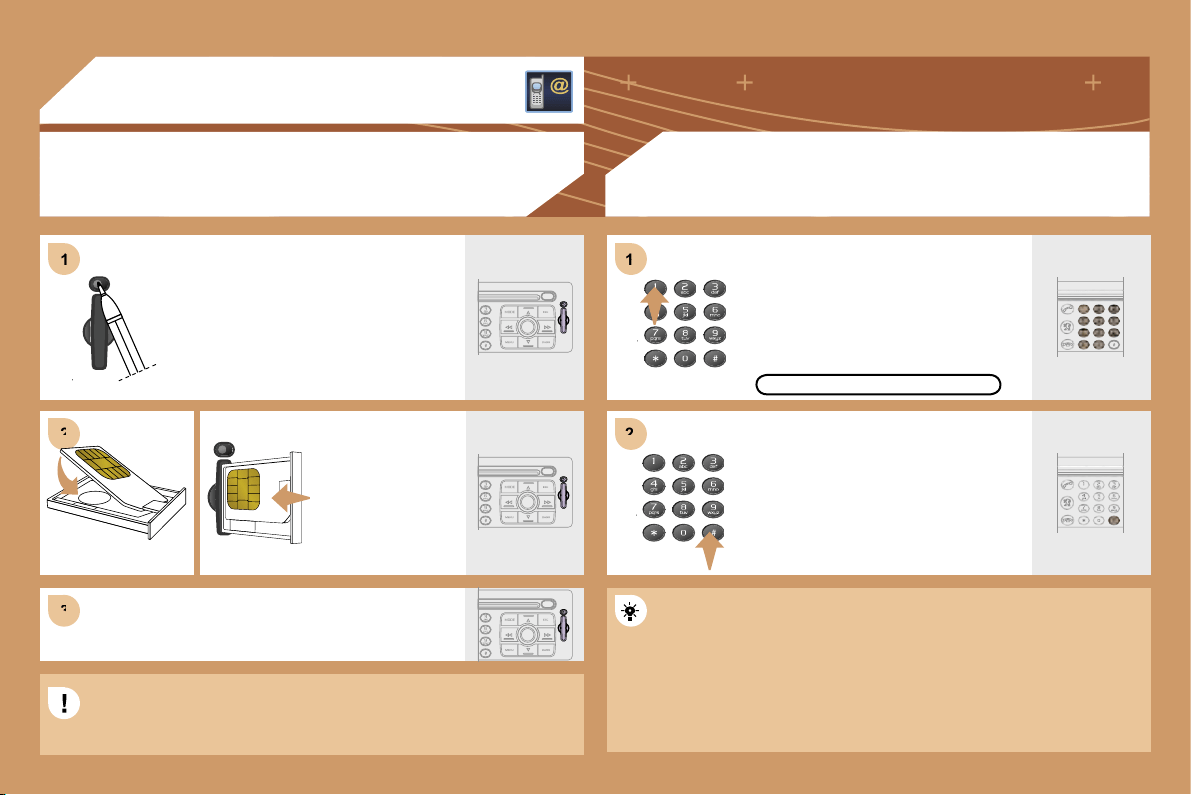
187
1
1
2
2
3
3
1
1
2
2
05 TELEPHONE
INSTALLING THE SIM CARD
(NOT SUPPLIED)
ENTERING THE PIN CODE
Access the slot by pressing the button
using the tip of a pen.
Install the SIM
card in the holder
and then insert it
in the slot.
To remove the SIM card, repeat step 1.
The SIM card must be installed and removed with the RT3 GPS
The SIM card must be installed and removed with the RT3 GPS
audio/telephone switched off and the ignition off.
Enter the PIN code on the keypad.
Confirm the PIN code by pressing
button #.
PIN CODE
When entering the PIN code, tick the STORE PIN tab to gain access
When entering the PIN code, tick the STORE PIN tab to gain access
to the telephone without having to enter this code when it is used
to the telephone without having to enter this code when it is used
subsequently.
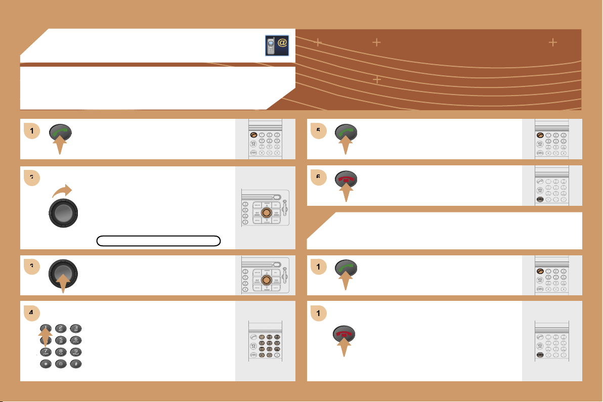
188
1
1
2
2
3
3
4
4
5
5
6
6
1
1
1
1
05 TELEPHONE
CALLING A CONTACT
Turn the dial and select the DIAL
function.
Press the PICK UP button to display
the superimposed telephone menu.
Press the dial to confirm the selection.
Dial the telephone number of your
contact using the alphanumeric
keypad.
Press the PICK UP button to call
the number dialled.
Press the HANG UP button to end
the call.
ACCEPTING OR REFUSING A CALL
Press the PICK UP button.
Press the HANG UP button.
The call will then be transferred to
your voice mailbox.
DIAL
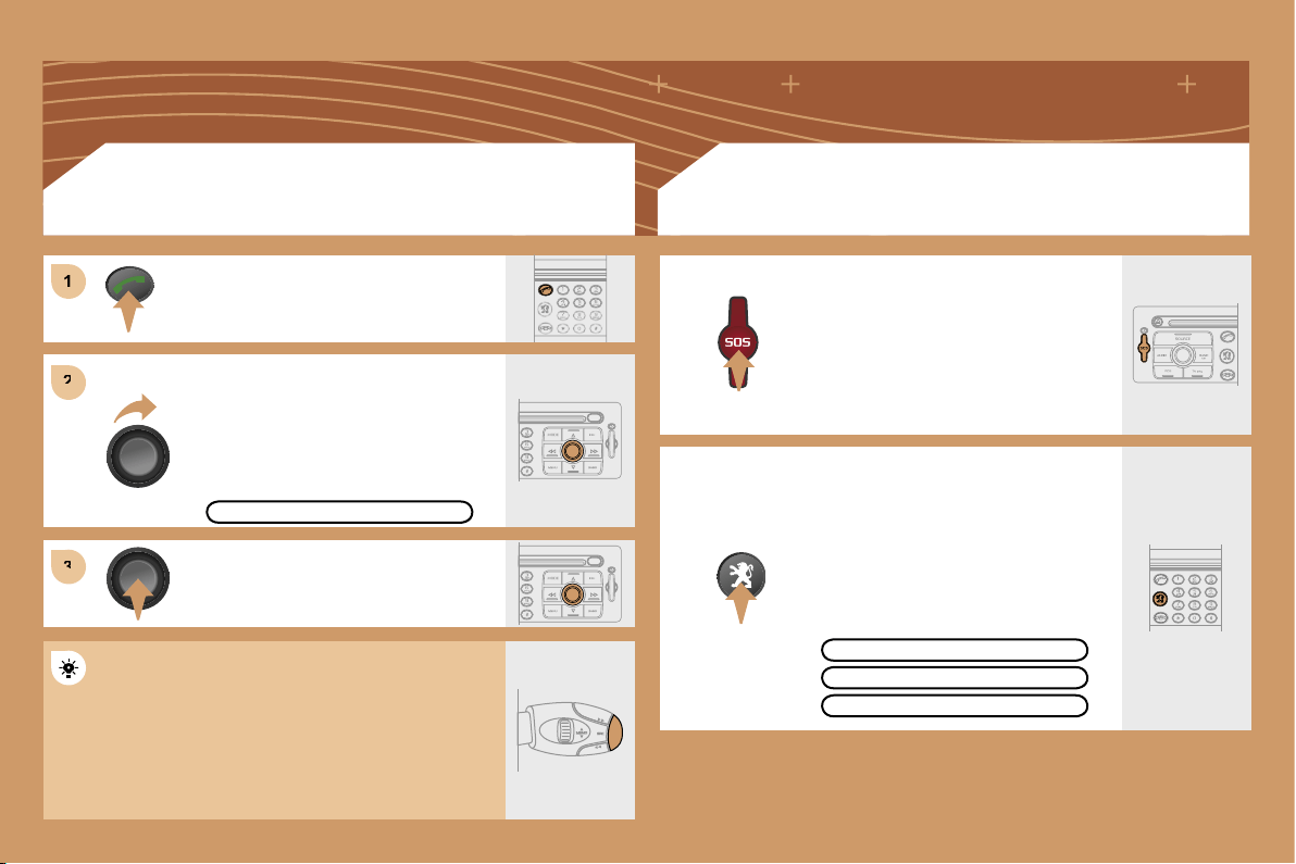
189
1
1
2
2
3
3
Turn the dial and select the MAILBOX
function.
Press the PICK UP button.
Press the dial to confirm the selection.
CONSULTING THE MAILBOX
CONSULTING THE SERVICES
Press the LION button to gain access
to the PEUGEOT services.
The services and options are subject to
conditions and availability.
In an emergency, press the SOS button
until you hear an audible signal and
a CONFIRMATION/CANCELLATION
screen is displayed.
The services and options are subject to
conditions and availability.
MAILBOX
OPERATOR SERVICES
PEUGEOT ASSISTANCE
CUSTOMER CONTACT CENTRE
Press the end of the steering wheel stalk for more
than 2 seconds to gain access to the telephone
menu: call log, directory, mailbox.
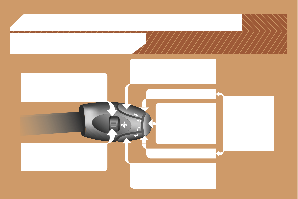
190
RADIO: selection of the previous stored station.
CD CHANGER: selection of the previous CD.
Selection of the previous item on a menu.
MP3: selection of the previous directory.
RADIO: selection of the next stored station.
CD CHANGER: selection of the next CD.
Selection of the next item on a menu.
MP3: selection of the next directory.
RADIO: automatic search for a higher frequency.
CD/CD CHANGER/MP3: selection of the next track.
Continuous press: fast forwards play.
RADIO: automatic search for a lower frequency.
CD/CD CHANGER/MP3: selection of the previous
track.
Continuous press: fast backwards play.
- Change of sound source.
- Confirmation of a selection.
- Pick up/Hang up the telephone.
- Press for more than 2 seconds:
access to the telephone menu.
Volume increase.
Volume decrease.
06 CONTROL SHORT-CUTS
STEERING WHEEL CONTROLS
Mute: by pressing the volume
increase and decrease
buttons simultaneously.
The sound is restored by
pressing one of the two
volume buttons.
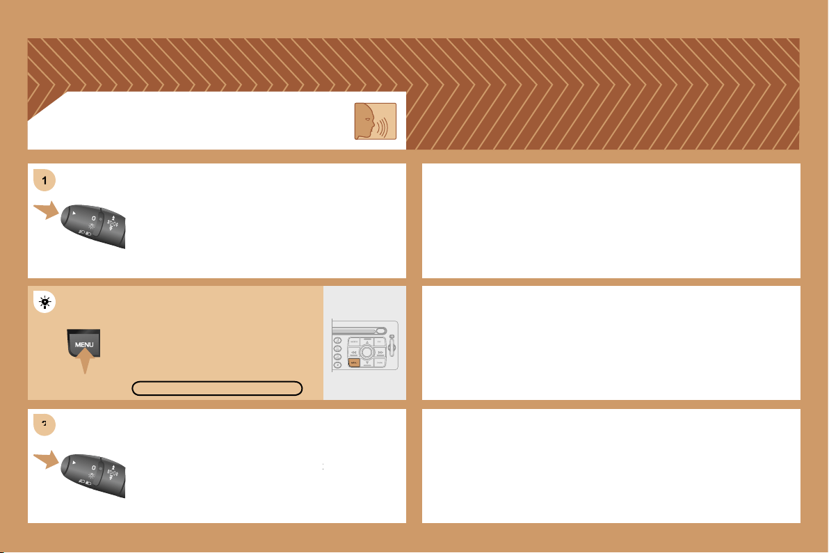
191
2
2
1
1
Press the end of the lights stalk to start the voice
Press the end of the lights stalk to start the voice
recognition.
Say the words one by one and wait for the audible
Say the words one by one and wait for the audible
confirmation signal between each word.
The list which follows is not exhaustive.
AUDIO
- RADIO then NEXT
- CD PLAYER then NEXT TRACK
- CD CHANGER then NEXT DISK
TELEPHONE
- TELEPHONE then REDIAL
- TELEPHONE then DIRECTORY then DESCRIPTION
- TELEPHONE then VOICE MAILBOX
GPS
- NAVIGATION then SHOW then DESTINATION
- NAVIGATION then STOP
- NAVIGATION then ZOOM IN
VOICE COMMANDS
To display the list of available voice commands, press
To display the list of available voice commands, press
the end of the lights stalk to start the voice recognition,
the end of the lights stalk to start the voice recognition,
then say HELP or WHAT CAN I SAY.
For the same operation, press and
hold the MENU button and select
the function
VOICE COMMANDS LIST.
VOICE COMMANDS LIST
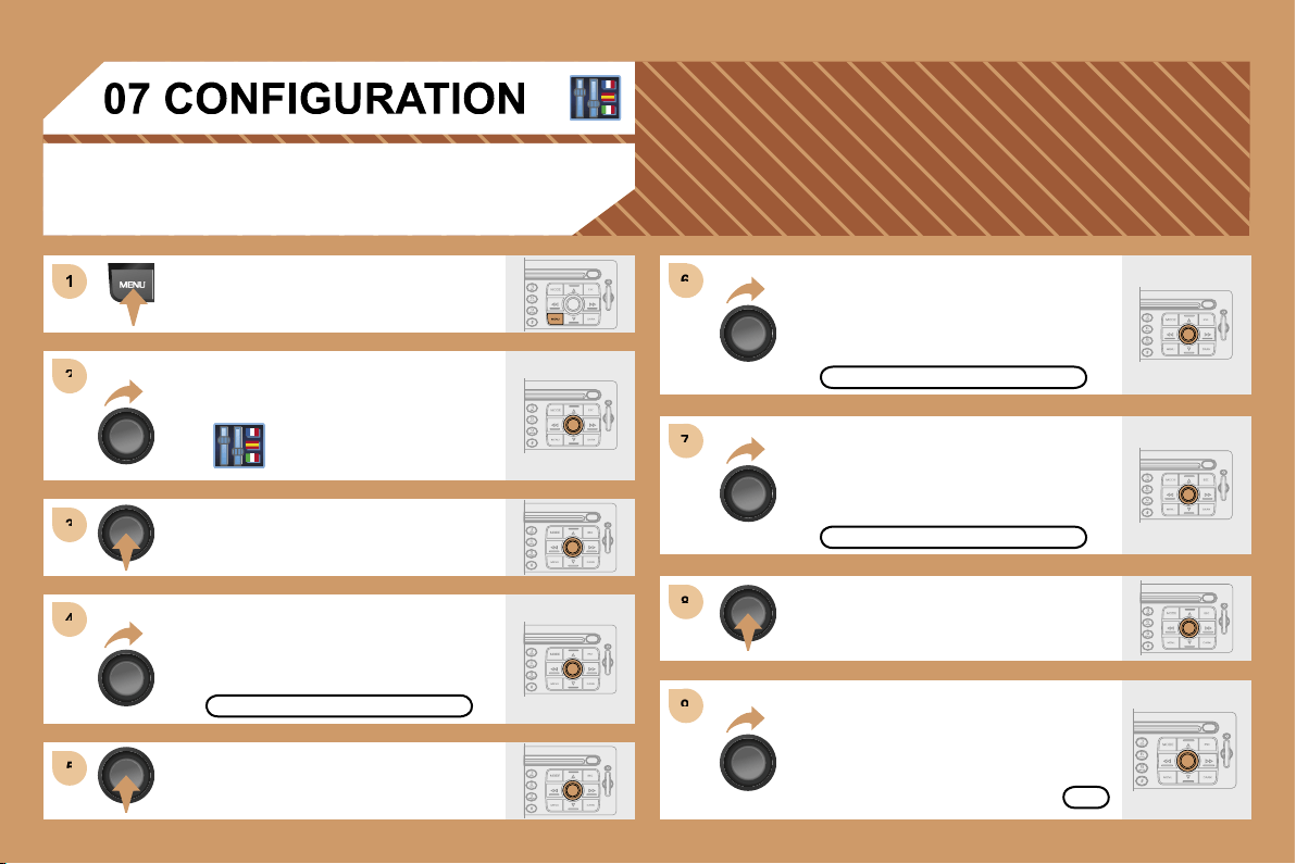
192
1
1
2
2
3
3
4
4
5
5
6
6
7
7
8
8
9
9
ADJUSTING THE DATE AND TIME
Press the MENU button.
Turn the dial and select the
CONFIGURATION function.
Press the dial to confirm the selection.
Turn the dial and select the
DISPLAY CONFIGURATION function.
Press the dial to confirm the
selection.
Turn the dial and select the
ADJUST THE DATE AND TIME
function.
Adjust the parameters one by one
confirming by pressing the OK
button. Next select the OK tab on
the display then confirm.
DISPLAY CONFIGURATION
ADJUST THE DATE AND TIME
OK
Press the dial to confirm the selection.
Turn the dial and select the
INTERNATIONAL PARAMETERS
function then confirm.
INTERNATIONAL PARAMETERS
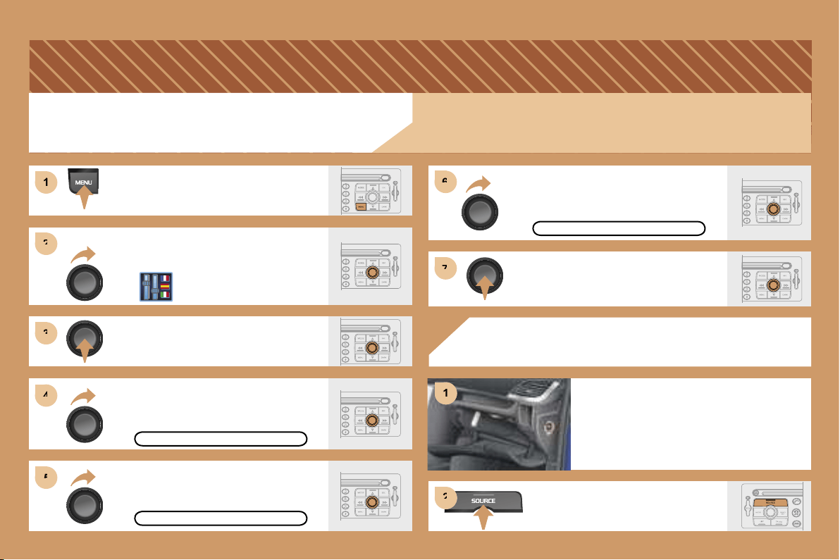
193
2
2
3
3
4
4
5
5
6
6
7
7
1
1
1
1
2
2
ACTIVATING THE AUXILIARY INPUT (AUX)
Press the MENU button.
Turn the dial and select the
CONFIGURATION function.
Press the dial to confirm the selection.
Turn the dial and select the DISPLAY
CONFIGURATION function then
confirm.
DISPLAY CONFIGURATION
Turn the dial and select the SOUND
function then confirm.
ACTIVATE AUX INPUT
SOUND
Turn the dial and select the ACTIVATE
AUX INPUT function.
USING THE AUXILIARY INPUT (AUX)
CABLE NOT SUPPLIED
Press the SOURCE button several
times in succession and select AUX.
Connect the portable equipment
(MP3 player…) to the audio sockets
(white and red, RCA type) located
in the glove box.
Press the dial to confirm the selection.
The auxiliary input permits the connection of portable equipment
(MP3 player...).
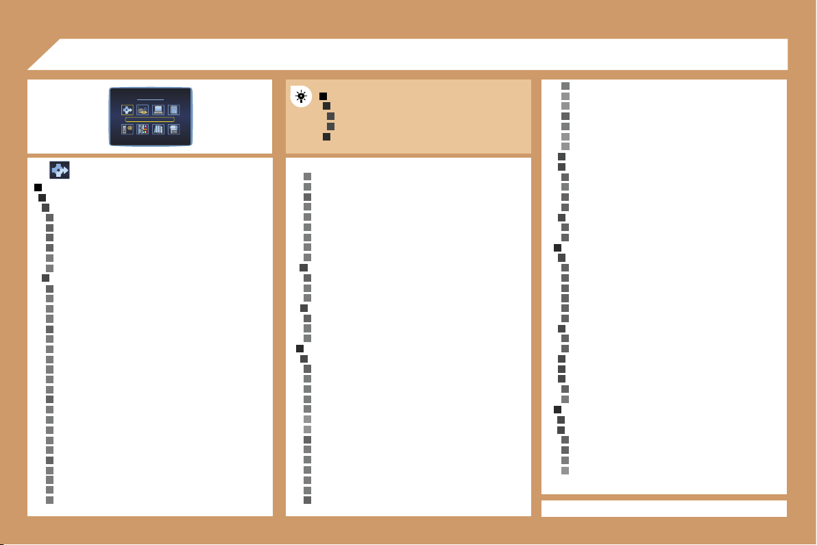
194
1
2
3
2
3
1
2
3
4
5
4
4
4
3
4
5
5
4
5
5
5
5
5
5
4
5
5
5
5
5
4
5
5
5
4
5
5
5
5
5
5
3
4
5
5
3
4
5
5
2
3
4
5
5
5
5
6
6
4
5
5
5
5
6
6
4
5
6
6
3
3
4
5
4
4
3
4
4
2
3
4
4
4
4
4
4
3
4
4
3
3
3
4
5
2
3
3
4
4
5
6
5
5
5
5
5
5
5
4
* Function not available at present.
08 DISPLAY FLOW CHART
MAIN FUNCTION
CHOICE A
choice A1
choice A2
CHOICE B...
DT
parks & gardens
theme parks
transport & automobile
ports, airports
station, bus stations
automatic checks*
vehicle hire
rest areas, car parks
service stations, garages
directory
nav directory
town, street, n°
ok
previous destinations
list of destinations
town, street, n°
ok
STAGES AND ROUTES
add a stage
enter an address
town
street
junction n°
gps
longitude
latitude
choice of a service
administration & security
hotels, restaurants & businesses
culture, tourism & shows
sports centres & outdoor pursuits
transport & automobile
directory
nav directory
town, street, n°
ok
previous destinations
list of destinations
town, street, n°
ok
order/delete stages
divert route
divert route over 2 km
the best diversion possible is 3 km. continue?
range 1-50
ok
chosen destination
town, street, n°
change
GUIDANCE OPTION
define the calculation criteria
the fastest
the shortest
distance/time
with tolls
with ferry
traffic info
adjust speech synthesis
volume
activate/deactivate
activate/deactivate street names
description of the cd-rom
delete the previous destinations
do you want to delete the list of previous destinations?
yes/no
TMC TRAFFIC INFORMATION
consult the messages
filter the TMC traffic information
activate/deactivate the route filter
filter by event
traffic information
traffic information
NAVIGATION/TRAFFIC INFO
CHOICE OF DESTINATION
enter an address
town
street
junction n°
gps
longitude
latitude
choice of a service
administration & security
town halls, town centre
universities, colleges
hospitals
hotels, restaurants & businesses
hotels
restaurants
vineyards
business centres
supermarkets, shopping
craft centres
culture, tourism & shows
tourism, historical monuments
culture, museums & theatres
shows & exhibitions
casinos & nightlife
cinemas
sports centres & outdoor pursuits
sports centres, complexes
golf courses
skating rinks, bowling alleys
winter sports centres
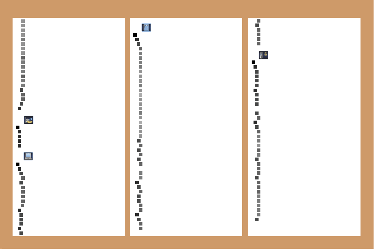
195
6
5
5
3
4
2
5
4
5
5
4
3
6
6
6
4
5
1
2
2
2
2
1
2
3
3
4
4
4
4
4
4
3
3
3
2
3
5
5
5
5
6
6
5
6
7
6
6
5
3
4
3
4
3
4
5
5
2
3
4
3
3
4
4
2
3
4
4
1
2
3
4
6
6
7
6
6
6
6
4
3
4
4
4
4
1
2
3
2
3
3
3
4
2
3
4
5
6
5
4
5
3
4
4
4
3
4
4
4
5
5
5
5
5
3
3
3
3
3
6
6
6
2
AUDIO FUNCTIONS
ACTIVATE/DEACTIVATE RDS ALTERNATIVE FREQUENCIES
ACTIVATE/DEACTIVATE REGIONAL MODE
ACTIVATE/DEACTIVATE RADIO TEXT INFO
ACTIVATE/DEACTIVATE CD DETAILS INFO
road closures
road restrictions
road conditions
weather & visibility
urban information
parking
public transport
demonstrations
geographical filter
around the vehicle
around a place/select
filter radius 50 km
choice of TMC station
station name
next station
speech synthesis
volume
activate/deactivate
activate/deactivate presentation of messages
RESUME/STOP GUIDANCE
TRIP COMPUTER
TRIP COMPUTER CONFIGURATION
enter distance to destination
0 km
select units
l/100 & km
mpg & miles
km/l & km
°c/°f
bar, psi
DIAGNOSTICS
warning log
equipment backup supply
gps coverage
STATUS OF FUNCTIONS
list of functions
DIRECTORY
MANAGEMENT OF DIRECTORY FILES
consult or change a file
entire directory
name
voice recording
notes
address
town
street
n°
number
display
list of numbers
change
add
delete
e-mail
display
list of numbers
change
add
delete
add a file
description
delete a file
entire directory
delete all files
do you want to delete all of the files in the directory
(non sim)?
yes
no
CONFIGURATION OF THE DIRECTORY
select a directory
user xxxx
name a directory
select the starting directory
user xxx
last directory used
FILE TRANSFER
infrared exchange
send all files
send one file
receive by infrared
exchange with the sim card
send all files
send one file
receive all files
receive one file
TELEPHONE AND TELEMATIC SERVICES
CALL
calls log
dial
directory
voice mail
SERVICE
customer contact centre
PEUGEOT
assistance
PEUGEOT
mobile services
(if services available and/or activated)
messages received
list of v-cards
TELEPHONE FUNCTIONS
network
network search mode
automatic mode
manual mode
list of networks
networks available
list of networks
duration of calls
partial counter
total duration
zero reset
manage the pin code
activate
store the pin code
change the pin code
entering the pin code
old code
> new code
confirmation
>> correct
call options
196
4
5
5
4
5
3
2
3
4
3
4
3
4
4
5
6
6
5
6
2
3
4
4
4
3
4
4
3
4
5
6
6
5
6
6
5
6
5
6
4
5
5
3
4
5
5
5
4
5
5
5
5
5
3
4
2
4
5
2
3
4
2
3
2
3
2
4
4
3
4
4
4
4
4
4
3
4
4
4
4
4
3
4
4
4
4
4
4
3
4
4
4
4
4
1
3
2
4
4
2
3
2
4
4
3
3
3
1
5
4
1
delete the list of calls and sms
do you want to delete the list of calls and sms
from the equipment?
configure the calls
displaying of my number
automatic pick-up after 3 rings
ring options
for voice calls
volume
type of ring
for text messages (sms)
text message buzzer
voice call diversion n°
TEXT MESSAGES (SMS)
reading text messages received
list of text messages received
sending a text message
list of saved text messages
writing a text message
text message
message sent
delete the list of text messages
CONFIGURATION
DISPLAY CONFIGURATION
select the colours
6 colours
night
automatic day/night
luminosity & brightness
luminosity
brightness
sound
speech synthesis adjustment
volume of guidance instructions
volume
activate/deactivate
volume of other messages
volume
activate/deactivate
select a voice
male/female
speech synthesis
activate/deactivate
voice command adjustment
volume
activate/deactivate
aux input
activate/deactivate
international parameters
adjust the date & time
day, month, year
time, 12 h, 24 h, am/pm
adjusting the minutes on gps
select the units
l/100 & km
mpg & miles
km/l & km
°c/°f
bar, psi
choice of language
list of languages available
DEFINE THE VEHICLE PARAMETERS
according to vehicle
MAP
MOVE THE MAP
MAP ORIENTATION
north oriented map
vehicle oriented map
CENTRE AROUND VEHICLE
MAP DETAILS
administration & security
town halls, town centre
universities, colleges
hospitals
hotels, restaurants & businesses
hotels
restaurants
vineyards
business centres
supermarkets, shopping
craft centres
culture, tourism & shows
tourism, historical monuments
culture, museums & theatres
shows & exhibitions
casinos & nightlife
cinemas
sports centres & outdoor pursuits
sports centres, complexes
golf courses
skating rinks, bowling alleys
winter sports centres
parks & gardens
theme parks
transport & automobile
ports, airports
station, bus stations
automatic checks*
vehicle hire
rest areas, car parks
service stations, garages
STORE THE CURRENT POSITION
description
deleted
VIDEO
ACTIVATE VIDEO MODE
VIDEO PARAMETERS
display formats
16/9 (full screen)
4/3 (conventional)
adjust brightness
set colours
set contrast
Flow chart version 6.6
* Function not available at present.
209
QUESTION
SOLUTION
RESPONSE
There is a difference in
sound quality between
the different audio
sources (radio, CD, CD
changer...).
Check that the audio settings (Volume, Bass,
Treble, Ambience, Loudness) are adapted to
the sources listened to. It is advisable to set
the AUDIO functions (Bass, Treble, Front-Rear
Balance, Left-Right Balance) to the middle
position, select the musical ambience "None"
and set the loudness correction to the "Active"
position in CD mode or to the "Inactive" position
in radio mode.
For optimum sound quality, the audio settings (Volume, Bass, Treble,
Ambience, Loudness) can be adapted to the different sound sources,
which may result in audible differences when changing source (radio, CD,
CD changer...).
The CD is ejected
automatically or is not
played by the player.
- Check that the CD is inserted in the player the
right way up.
- Check the condition of the CD: the CD cannot
be played if it is too damaged.
- Check the content in the case of a recorded
CD: consult the advice in the Audio section.
- The audio equipment’s CD player does not
play DVDs.
- Due to inadequate quality, certain recorded
CDs will not be played by the audio system.
- The CD changer does not play MP3 CDs.
The CD is inserted upside down, is unplayable, does not contain any audio
data or contains an audio format which the player cannot play.
The CD is protected by an anti-pirating protection system which is not
recognised by the audio equipment.
FREQUENTLY ASKED QUESTIONS
The CD player sound
is poor.
The CD used is scratched or of poor quality.
Insert good quality CDs and store them in
suitable conditions.
The audio equipment settings (bass, treble, ambiences) are unsuitable.
Set the treble or bass level to 0, without selecting
an ambience.

210
QUESTION
SOLUTION
RESPONSE
The stored stations do
not function (no sound,
87.5 Mhz is displayed...).
An incorrect waveband is selected.
Press the BAND AST button to return to the
waveband (AM, FM1, FM2, FMAST) on which the
stations are stored.
The traffic announcement
(TA) is displayed. I do
not receive any traffic
information.
Tune to a radio station which broadcasts traffic
information.
The radio station is not part of the regional traffic information network.
The quality of reception
of the radio station
listened to gradually
deteriorates or the
stored stations do not
function (no sound,
87.5 Mhz is
displayed...).
The vehicle is too far from the transmitter used by the station listened to or
there is no transmitter in the geographical area through which the vehicle
is travelling.
The environment (hills, buildings, tunnels, basement car parks...) block
reception, including in RDS mode.
The aerial is absent or has been damaged (for example when going
through a car wash or into an underground car park).
Activate the RDS function to enable the system
to check whether there is a more powerful
transmitter in the geographical area.
This phenomenon is normal and does not
indicate a failure of the audio equipment.
Have the aerial checked by a
PEUGEOT
dealer.
PEUGEOT
PEUGEOT
Sound cut-outs of 1 to
2 seconds in radio mode.
During this brief sound cut-out, the RDS searches for any frequency
permitting better reception of the station.
Deactivate the RDS function if the phenomenon
is too frequent and always on the same route.
With the engine off,
the audio equipment
switches off after a few
minutes of use.
When the engine is switched off, the audio equipment operating time
depends on the battery charge.
The switch-off is normal: the audio equipment switches to economy mode
and switches off to prevent discharging of the vehicle’s battery.
Start the vehicle’s engine to increase the battery
charge.
The message "the audio
system is overheated"
appears on the display.
Switch the audio system off for a few minutes to
allow the system to cool.
In order to protect the installation if the surrounding temperature is too high,
the audio equipment switches to an automatic thermal protection mode
leading to a reduction of the volume or stopping of the playing of the CD.
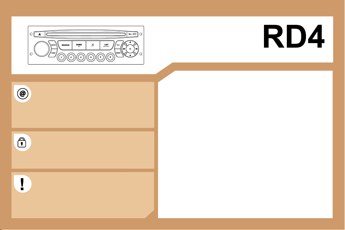
197
AUDIO EQUIPMENT/HANDS-FREE KIT
CONTENTS
• 01 First steps pg. 198
• 02 General menu pg. 199
• 03 Audio pg. 200
• 04 Hands-free kit pg. 203
• 05 Control short-cuts pg. 204
• 06 Configuration pg. 205
• 07 Display flow charts pg. 206
• Frequently asked questions pg. 209
The INFOTEC website provides additional, animated
information on the RD4. It can be consulted at the
following address:
http://public.infotec.peugeot.com.
Registering on the site allows access to the vehicle
handbook documentation, which can be consulted free
of charge.
The RD4 audio equipment is coded in such a way that
it will only operate in your vehicle. If it is to be installed
in another vehicle, contact your PEUGEOT dealer for
configuration of the system.
For safety reasons, the driver must carry out operations
which require prolonged attention while the vehicle is
stationary.
When the engine is off and in order to prevent
discharging of the battery, the RD4 audio equipment may
switch off after a few minutes.
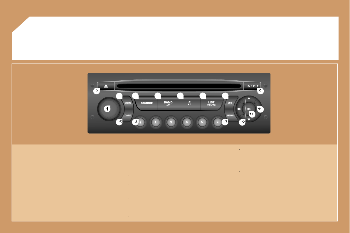
198
1
1
2
2
10
10
11
11
13
13
14
14
15
15
3
3
4
4
5
5
6
6
7
7
8
8
9
9
12
12
01 FIRST STEPS
1 -
On/Off and volume adjustment.
1 -
1 -
2 -
CD eject.
2 -
2 -
3 -
Selection of the screen display mode.
3 -
3 -
4 -
Selection of the source: radio, CD and CD changer.
4 -
4 -
5 -
Selection of the FM1, FM2, FMast and AM wavebands.
5 -
5 -
6 -
Setting the audio options:
6 -
6 -
front/rear balance, left/right balance, loudness, sound
ambiences.
7 -
Displaying of the list of local stations, of the tracks on the CD
7 -
7 -
or of the MP3 directories.
8 -
Abandon current operation.
8 -
8 -
9 -
TA (Traffic Announcement) function on/off.
9 -
9 -
Long press: access to the PTY (TYpes of radio Programme)
mode.
10 -
Confirmation.
10 -
10 -
11 -
Automatic search for a lower/higher frequency.
11 -
11 -
Selection of previous/next CD or MP3 track.
12 -
Selection of a lower/higher radio frequency.
12 -
12 -
Selection of the previous/next CD.
Selection of the previous/next MP3 directory.
13 -
Displaying of the general menu.
13 -
13 -
14 -
Buttons 1 to 6:
14 -
14 -
Selection of a stored radio station.
Selection of a CD in the CD changer.
Long press: storing of a station.
15 -
The DARK button changes the display on the screen to
15 -
15 -
improve driving comfort at night.
1st press: lighting of the top banner only.
2nd press: black screen display.
3rd press: return to the standard display.
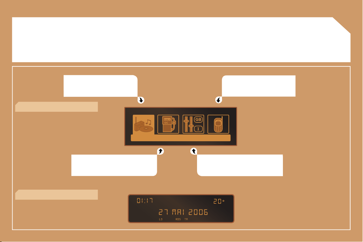
199
02 GENERAL MENU
AUDIO FUNCTIONS: radio, CD,
options.
TRIP COMPUTER: distance entering,
warnings, status of functions.
TELEPHONE: hands-free kit,
matching, management of a
communication.
PERSONALISATION-CONFIGURATION:
vehicle parameters, display, languages.
> MONOCHROME DISPLAY C
> MONOCHROME DISPLAY A
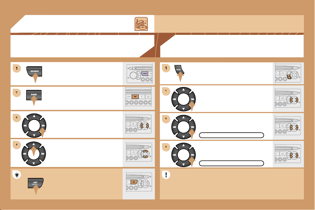
200
1
1
2
2
3
3
4
4
2
2
4
4
3
3
1
1
03 AUDIO
RADIO
SELECTING A STATION
Press the SOURCE button several
times in succession and select the
radio.
Press the BAND AST button to select
a waveband: FM1, FM2, FMast, AM.
Briefly press one of the buttons to
carry out an automatic search of the
radio stations.
Press one of the buttons to carry out a
manual search of the radio stations.
Press the LIST REFRESH button to
display the list of stations received
locally (30 stations maximum).
To update this list, press for more than
two seconds.
Select ACTIVATE FREQUENCY
FOLLOWING (RDS) then press OK.
RDS appears on the display.
Select the FM WAVEBAND
PREFERENCES function then press
OK.
Select AUDIO FUNCTIONS then
press OK.
Press the MENU button.
FM WAVEBAND PREFERENCES
ACTIVATE FREQUENCY FOLLOWING
The external environment (hills, buildings, tunnels, basement car parks) may block reception,
including in RDS mode. This is a normal effect of the way in which radio waves are transmitted and
does not indicate any failure of the audio equipment.
RDS
The RDS, if displayed, enables you to continue listening to the same station by means
of frequency following. However, in certain conditions, this RDS station is not followed
throughout the country as radio stations do not cover 100 % of the territory. This explains
the loss of reception of the station during a journey.
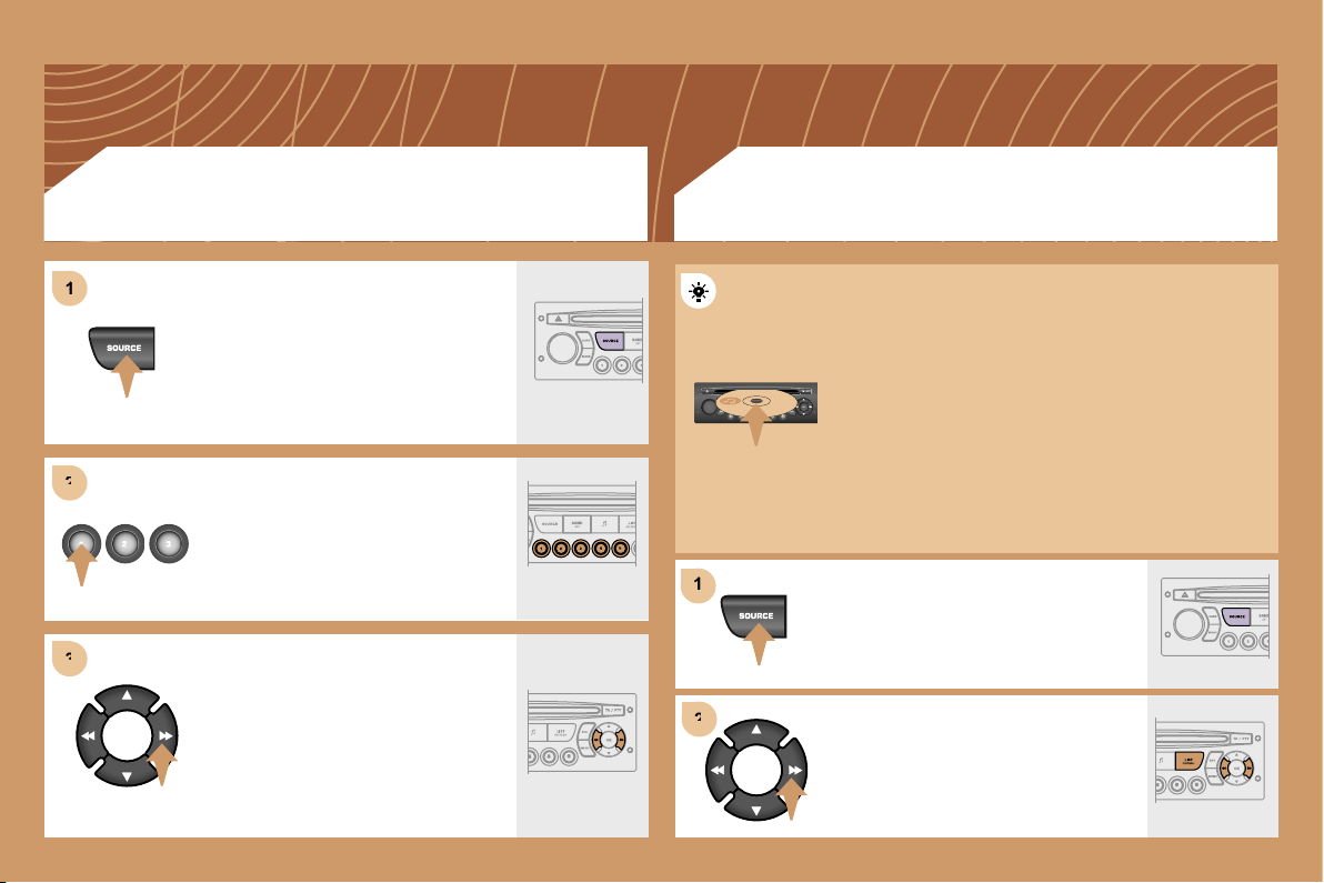
201
1
1
2
2
3
3
1
1
2
2
CD CHANGER
PLAYING A CD (NOT MP3 COMPATIBLE)
Insert the CDs in the changer one by
one.
Press the SOURCE button several
times in succession and select CD
CHANGER.
Press one of the buttons on the
numeric keypad to select the
corresponding CD.
Press one of the buttons to select a
track on the CD.
Press and hold one of the buttons for
fast forwards or backwards play.
Insert circular compact discs only.
Some anti-pirating systems, on original discs or CDs
copied using a personal recorder, may cause faults
which are no reflection on the quality of the original
player.
Without pressing the EJECT button, insert a CD in the
player, play begins automatically.
To play a disc which has already been
inserted, press the SOURCE button
several times in succession and select
CD.
Press one of the buttons to select a
track on the CD.
Press the LIST REFRESH button to
display the list of tracks on the CD.
CD
PLAYING A CD
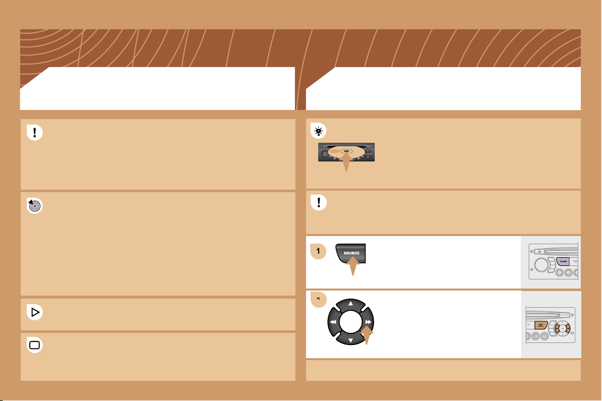
202
1
1
2
2
Insert an MP3 compilation in the player.
The audio equipment searches for all of the music
tracks, which may take anything between a few
seconds and several tens of seconds, before play
begins.
On a single disc, the CD player can read up to 255 MP3 files spread
over 8 directory levels. However, it is advisable to keep to a limit of
two levels to reduce the access time before the CD is played.
CD
PLAYING AN MP3 COMPILATION*
MP3 CD
INFORMATION AND ADVICE
The MP3 format, an abbreviation of MPEG 1.2 & 2.5 Audio
Layer 3, is an audio compression standard which permits the
recording of several tens of music files on a single disc.
The playing and displaying of an MP3 compilation may depend on
the recording programme and/or the parameters used.
In order to be able to play a recorded CDR or CDRW, when recording
select standards ISO 9660 level 1.2 or Joliet.
If the disc is recorded in another format, it may not be played
correctly.
It is recommended that the same recording standard is always used
for an individual disc, with as low a speed as possible for optimum
sound quality.
In the particular case of a multi-session CD, the Joliet standard is
recommended.
The audio equipment will only play files with the extension ".mp3". No
other type of file (.wma, .mp4...) can be played.
It is advisable to restrict file names to 20 characters without using
special characters (e.g.: " " ? ; ) to avoid any playing or displaying
problems.
To play a disc which has already been
inserted, press the SOURCE button
several times in succession and select
CD.
Press one of the buttons to select a
track on the CD.
Press the LIST REFRESH button to
display the list of directories of the
MP3 compilation.
* According to specification.
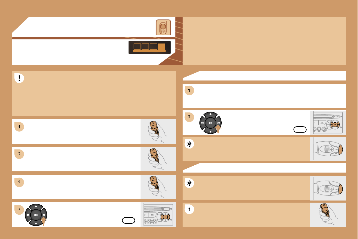
203
1
1
2
2
3
3
1
1
2
2
4
4
1
1
04 HANDS-FREE KIT
MATCHING A TELEPHONE
DISPLAY C
For safety reasons and because they require prolonged attention on
the part of the driver, the operations for matching of the Bluetooth
mobile telephone with the RD4 hands-free kit must be carried out
with the vehicle stationary and the ignition on.
Select the accessory which corresponds to the
name of the vehicle, a superimposed configuration
display appears on the multifunction display.
Activate the telephone’s Bluetooth function and
carry out a search of the Bluetooth accessories
present for the telephone.
Select the YES tab on the display using
the buttons then confirm by pressing OK.
Enter the vehicle’s authentication code (=1234).
Depending on the telephone, you may be asked
to enter this code before the superimposed
configuration display appears.
YES
YES
The services offered by the hands-free kit depend on the network, the SIM
card and the compatibility of the Bluetooth equipment used.
Consult your telephone’s manual and your operator to find out which
services are available to you. A list of mobile telephones which offer the
best range of services is available from the network. Contact a PEUGEOT
dealer.
RECEIVING A CALL
An incoming call is announced by a ring and a superimposed display
on the multifunction display.
Select the YES tab on the display
using the buttons and confirm by
pressing OK.
Press the end of the steering wheel stalk to accept
the call.
Press and hold the end of the steering wheel stalk to
access your directory.
To dial a number, use the keypad on your telephone.
MAKING A CALL
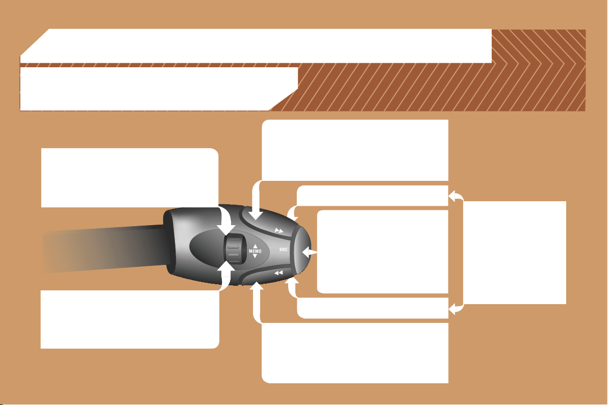
204
RADIO: selection of the next stored station.
CD CHANGER: selection of the next CD.
Selection of the next item on a menu.
MP3: selection of the next directory.
RADIO: selection of the previous stored station.
CD CHANGER: selection of the previous CD.
Selection of the previous item on a menu.
MP3: selection of the previous directory.
RADIO: automatic search for a higher frequency.
CD/CD CHANGER/MP3: selection of the next track.
CD/CD CHANGER: continuous press: fast forwards
play.
Selection of the previous item.
RADIO: automatic search for a lower frequency.
CD/CD CHANGER/MP3: selection of the
previous track.
CD/CD CHANGER: continuous press: fast
backwards play.
Selection of the next item.
Volume increase.
Volume decrease.
05 CONTROL SHORT-CUTS
Mute: by pressing
the volume increase
and decrease buttons
simultaneously.
The sound is restored by
pressing one of the two
volume buttons.
- Change of sound source.
- Confirmation of a selection.
- Pick up/Hang up the telephone.
- Press for more than 2 seconds:
access to the telephone menu.
STEERING WHEEL CONTROLS
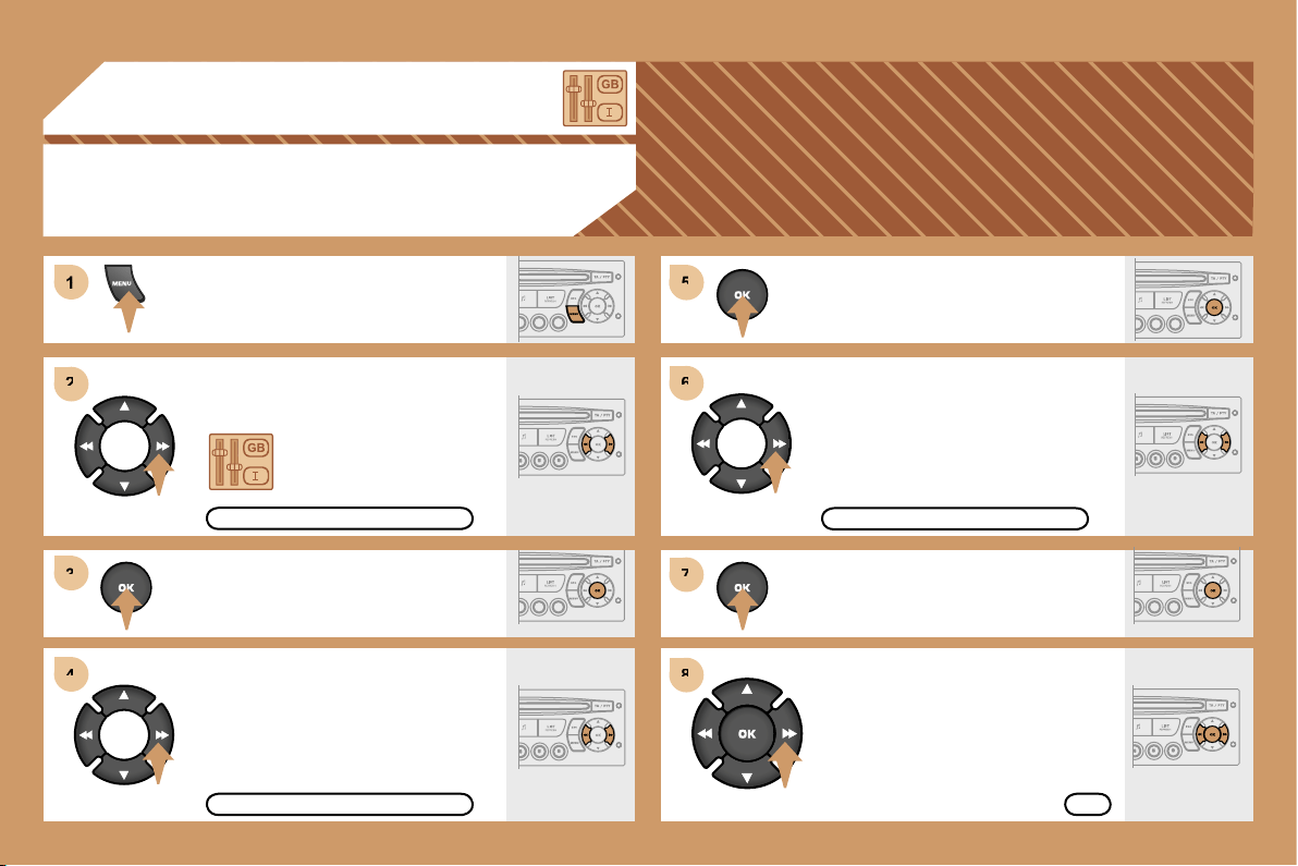
205
5
5
6
6
7
7
8
8
1
1
2
2
3
3
4
4
06 CONFIGURATION
ADJUSTING THE DATE AND TIME
DISPLAY C
Press the MENU button.
Using the arrows, select
the PERSONALISATION
CONFIGURATION
function.
Press to confirm the selection.
Using the arrows, select the
DISPLAY CONFIGURATION function.
Press to confirm the selection.
Press to confirm the selection.
Using the arrows, select the
ADJUST DATE AND TIME function.
Adjust the parameters one by one
confirming by pressing the OK button.
Next select the OK tab on the display
then confirm.
DISPLAY CONFIGURATION
ADJUST DATE AND TIME
OK
PERSONALISATION CONFIGURATION
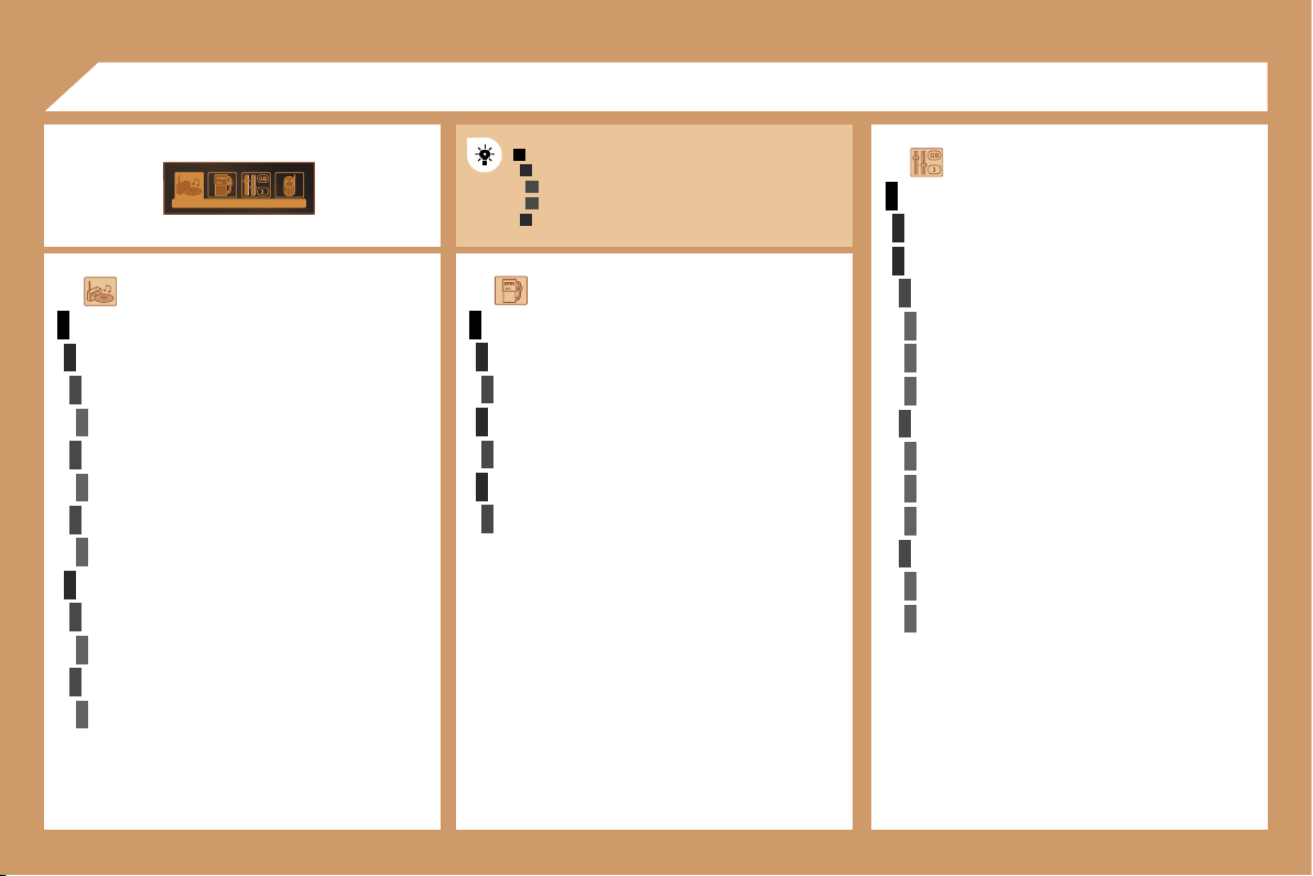
206
1
2
3
2
3
1
1
2
3
4
3
4
3
4
2
3
4
3
4
2
3
4
2
4
4
3
4
4
4
3
4
4
1
3
3
3
2
2
2
TRIP COMPUTER
ENTER DISTANCE TO DESTINATION
distance/x km
WARNING LOG
diagnostics
STATUS OF FUNCTIONS
functions activated or deactivated
AUDIO FUNCTIONS
FM BAND PREFERENCES
alternative frequencies
(RDS)
activate/deactivate
regional mode
(REG)
activate/deactivate
radio-text information
(RDTXT)
activate/deactivate
AUDIO CD PREFERENCES
cd changer repeat
(RPT)
activate/deactivate
track random play
(RDM)
activate/deactivate
07 DISPLAY FLOW CHART
monochrome C
MAIN FUNCTION
CHOICE A
C
hoice
A1
Choice A2
CHOICE B...
C
PERSONALISATION-CONFIGURATION
DEFINE THE VEHICLE PARAMETERS*
DISPLAY CONFIGURATION
video brightness adjustment
normal video
inverse video
brightness (- +) adjustment
date and time adjustment
day/month/year adjustment
hour/minute adjustment
choice of 12 h/24 h mode
choice of units
l/100 km - mpg - km/l
°Celsius/°Fahrenheit
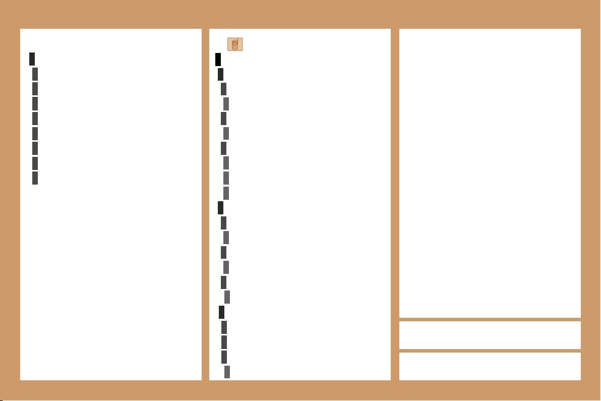
207
1
2
3
4
3
4
3
4
4
4
2
3
4
3
4
3
4
2
3
3
3
4
3
3
3
2
3
3
3
3
3
TELEPHONE
CONSULTING DIRECTORIES**
telephone directory
directory list
call log
call list
services directory
customer contact centre
breakdown call
emergency call
CONFIGURATION
deletion of a match
list of matches
consulting matches
list of matches
choice of a mobile to connect
list of mobiles
MANAGEMENT OF A COMMUNICATION
switch**
terminate the current call
secret mode
activate/deactivate
* The parameters vary according to vehicle.
CHOICE OF LANGUAGE
deutsch
english
espanol
français
italiano
nederlands
portugues
portugues-brasil
** According to compatibility of Bluetooth telephone
and service contract.
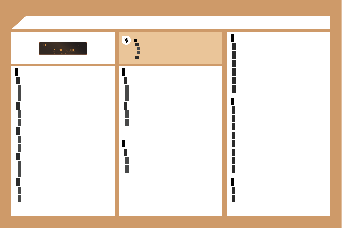
208
1
2
3
3
2
3
3
2
3
3
2
3
3
2
3
3
1
2
3
3
2
3
3
1
2
3
3
1
2
2
2
2
2
2
1
2
2
2
2
2
2
2
2
1
2
2
1
2
3
2
3
RADIO-CD
RDS SEARCH
active
inactive
REG MODE
active
inactive
INTROSCAN
active
inactive
CD REPEAT
active
inactive
RANDOM PLAY
active
inactive
VEHICLE CONFIG
REV WIPE ACT
active
inactive
GUIDE LAMPS
active
inactive
LANGUAGES
FRANCAIS
ITALIANO
NEDERLANDS
PORTUGUES
PORTUGUES-BRASIL
DEUTSCH
ENGLISH
ESPANOL
OPTIONS
ABANDON/CONSULT LIST OF FAULTS
functions activated (or not)
warning messages
DISPLAY ADJUST
YEAR
MONTH
DAY
HOUR
MINUTES
12 H/24 H MODE
UNITS
TEMPERATURE/°CELSIUS/°FAHRENHEIT
FUEL CONSUMPTION/ KM/L - L/100 - MPG
07 DISPLAY FLOW CHART
monochrome A
MAIN FUNCTION
CHOICE A
Choice A1
Choice A2
CHOICE B
...
A