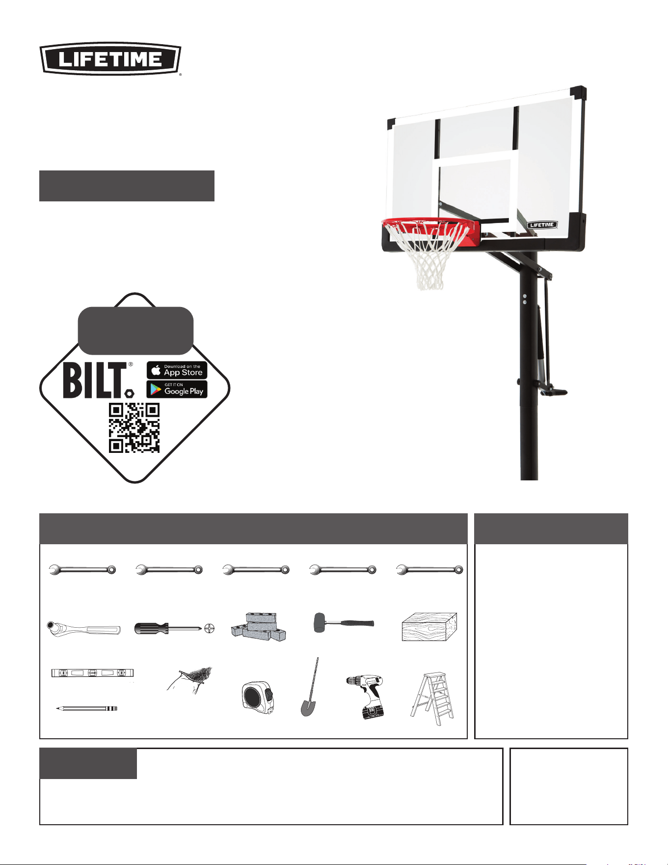
TOOLS REQUIRED TABLE OF CONTENTS
(x2) (x2) (x2) (x2) (x2)
(x1)
(x1)
1/2" (≈13 mm) 9/16" (≈14 mm) 11/16" (≈18 mm) 3/4" (≈19 mm) 1/2" (≈13 mm)
Icon Legend................................2
Warnings & Notices.....................3
Ground Preparation.....................4
Pole Assembly.............................9
Backboard-to-Rim Assembly......12
Backboard-to-Pole Assembly.......17
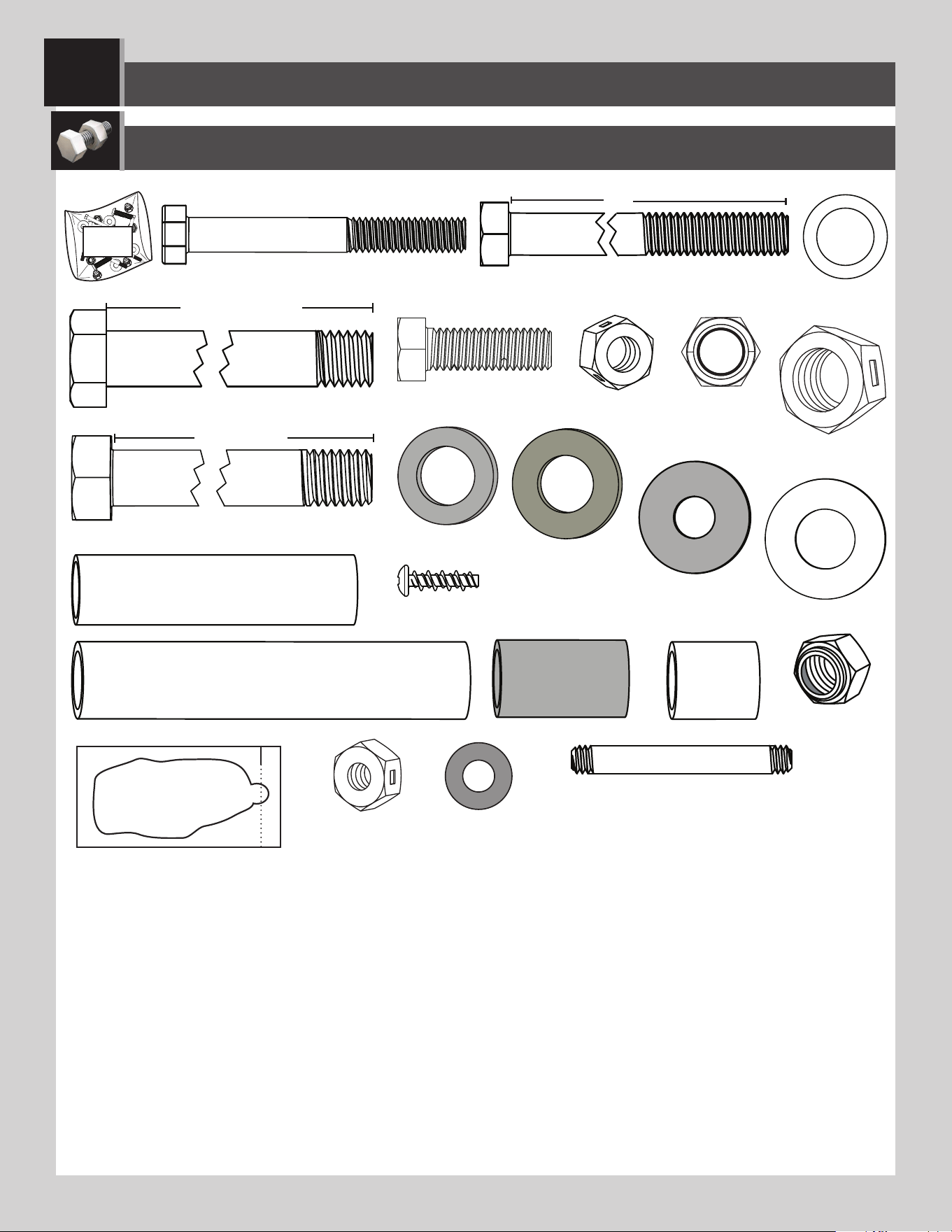
Parts Identifi er..........................i-iv
Handle Assembly......................24
Final Assembly..........................32
Maintenance.........................37
Warning Sticker........................38
Registration........................42
Warranty................................43
(x1)
(x1)
Concrete Mix
640 lb (291 kg)
Level
(x1)
1/2" (≈13 mm)
(x1)
(x1)
(x3)
(x1)
CONTACT LIFETIME CUSTOMER SERVICE:
Dial 1-800-225-3865
7:00 am–5:00 pm (M–F) MST
and 9:00 am–1:00 pm (Sat) MST
QUESTIONS?
Model Number: 90602
Product ID:
For Customer Service in Mainland
Europe and the United Kingdom,
E-mail: [email protected]
Live Chat:
www.lifetime.com/customerservice
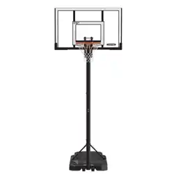
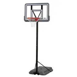
PUMP ADJUST
®
BASKETBALL SYSTEM
BEFORE ASSEMBLY:
• Requires 640 lb (291 kg) of concrete mix.
• Requires at least 72 hours (3 days) for concrete to cure, plus 3–4
hours to complete assembly steps.
• At least three (3) adults required for setup.
ASSEMBLY INSTRUCTIONS
MODEL 90602
Save this instruction in the event that the manufacturer must be contacted for replacement parts.
(≈4-6)
Bricks
3D ANIMATION
OF THE FULL ASSEMBLY
WATCH
SCAN THE
CODE
OR SEARCH
1184987,
1210184
2
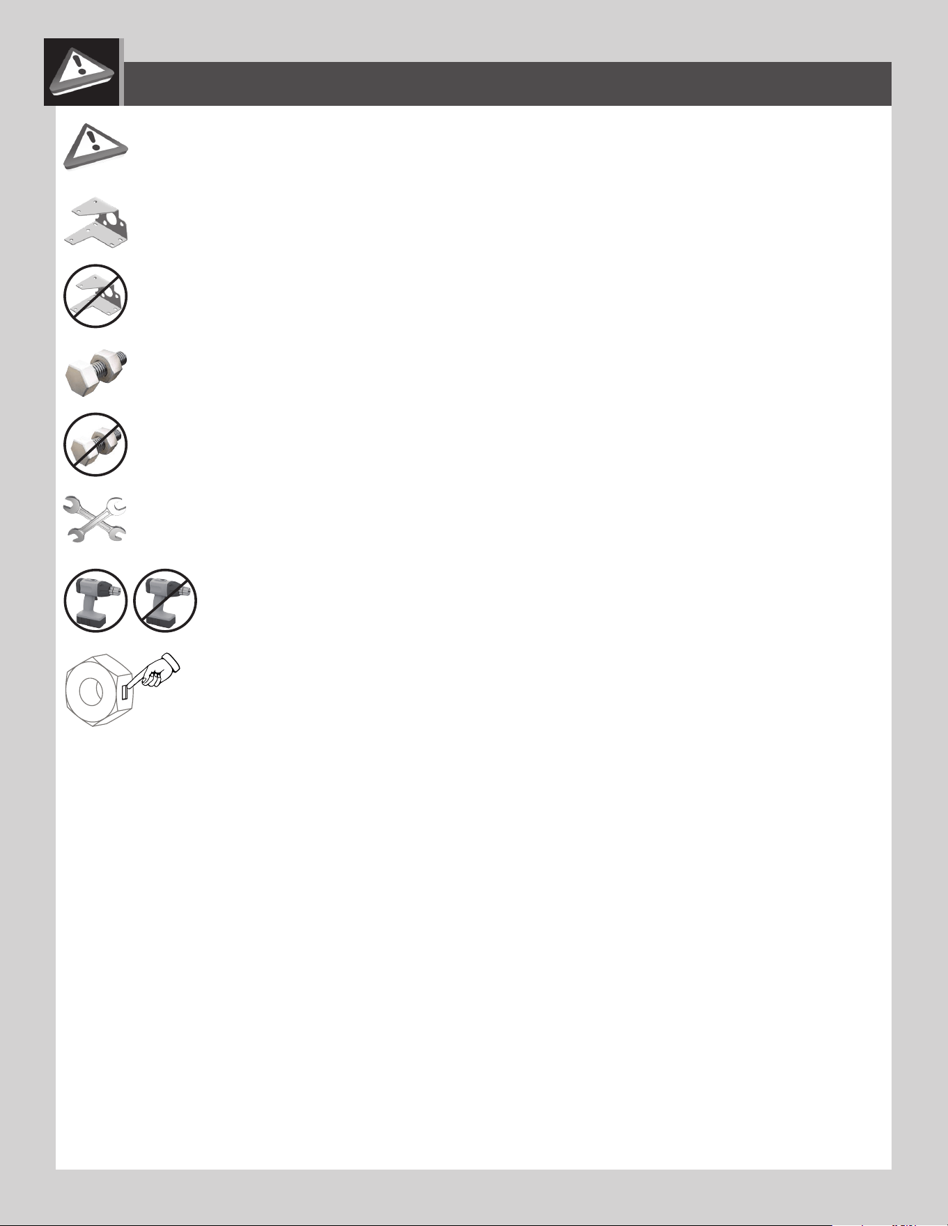
• Indicates the parts to be used for a section.
• Indicates special heed should be taken when reading.
• Indicates the hardware to be used for a section.
• Indicates the tools to be used for a section.
• Indicates no hardware required for a specifi c page.
• Indicates no parts required for a specifi c section.
• Indicates to use/not to use an electric drill for a specifi c step.
ICON LEGEND
• Indicates the use of a centerlock nut. A nut with this marking will require some effort to tighten.
This hardware was designed with this feature in order to prevent loosening later.
1220859
9/25/2021
3
WARNINGS & NOTICES
Most injuries are caused by misuse and/or not following instructions. Use caution when using this product.
To ensure safety, do not attempt to assemble this product without following the instructions carefully. Check entire box and inside all packing
material for parts and/or additional instruction material. Before beginning assembly, read the instructions and identify parts using the hardware
identifi er and parts list in this document. Proper and complete assembly, use and supervision are essential for proper operation and to reduce the
risk of accident or injury. A high probability of serious injury exists if this product is not installed, maintained, and operated properly.
FAILURE TO FOLLOW THESE WARNINGS MAY RESULT IN SERIOUS INJURY OR PROPERTY DAMAGE AND WILL VOID WARRANTY.
Owner must ensure that all players know and follow these rules for safe operation of the system.
• If using a ladder during assembly, use extreme caution.
• Three capable adults are recommended for this operation.
• Assemble the pole sections properly. Failure to do so could cause the pole sections to separate during play or transport.
• Before digging, contact utility company to locate underground power cables, gas, and water lines. Ensure that there are no
overhead power lines within 20' (7 m) radius of pole locations.
• Minimum operational height is 6'-6" (1.98 m) to the bottom of the backboard.
SAFETY INSTRUCTIONS
SAFE HANDLING OF THE GLASS BACKBOARD
BEFORE & DURING ASSEMBLY
1. Thoroughly inspect the backboard before beginning assembly. Do not use the backboard if there are any chips,
cracks, or other defects in the board. Call our customer service department if any problems are found.
2. Use extreme caution when handling or working around the backboard.
3. Keep tools, hardware, and other sharp and heavy objects away from the backboard.
4. Never rest the backboard directly on a hard surface, such as concrete or pavement. Always place cardboard or
other cushioning material between the backboard and the ground or other hard surfaces.
5. Always lay the backboard fl at. Never place it in a position where it might tip over and break.
6. Glass is very heavy. Always use at least two adults when picking up or moving the backboard.
General Handling & Care
1. Inspect the backboard before each use. Do not use the backboard if there are any chips, cracks, or other defects in
the board. If any signs of damage are found, follow the instructions for “handling broken glass” below.
2. Use extreme caution when handling or working around the backboard.
3. The backboard was designed for use with a basketball. Do not use other types of balls or other objects with the
system. Do not use this system for any purpose other than its designed purpose.
Handling Broken Glass
At the fi rst sign of breakage:
1. Keep everyone, especially children, away from the immediate area of the backboard.
2. Put on eye protection, and wear thick utility gloves and long sleeves. Small pieces of tempered glass may pop out of
the backboard.
3. Lower the backboard to its lowest height, and completely cover the backboard with a tarp.
4. Do not remove the backboard from the system without fi rst lowering the system to its lowest setting. Carefully read
and follow the “removing backboard from system” instructions below.
Removing Backboard from System
1. With the backboard at its lowest height, have at least two capable adults support the system while one adult
removes the hardware securing the pole to the playing surface.
2. Have at least three capable adults carefully lay the system down. Make sure to rest the rim on a sheet of cardboard
or other non-abraisive surface.
3. Loosen and remove the hardware from the steps performed in the backboard to pole assembly section of this
manual in reverse order. Keep the hardware.
4. Loosen and remove the hardware from the steps performed inthe backboard to rim assembly section to safely
remove the rim. Keep all parts and hardware from this section for reassembly.
4
1
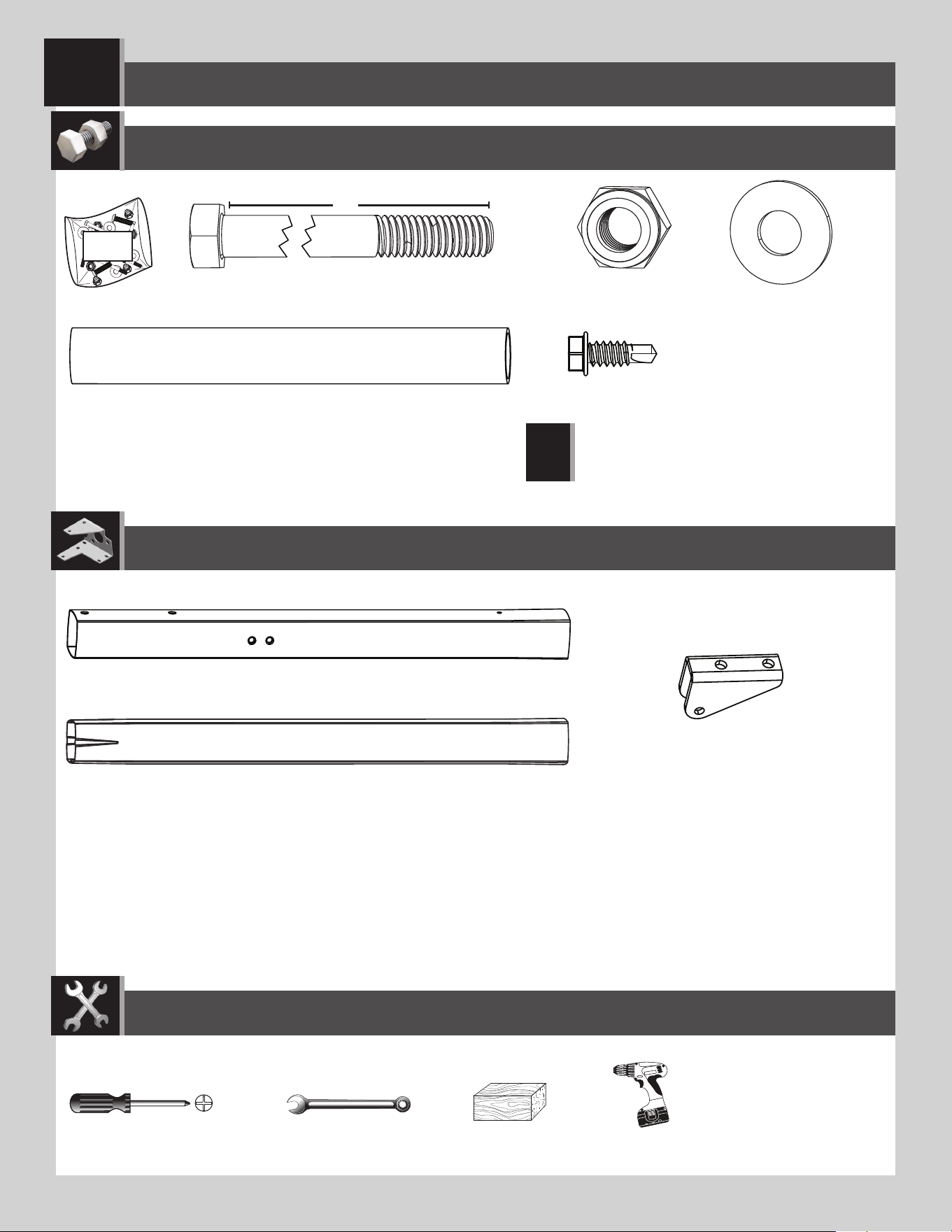
Metal parts
Hardware bag
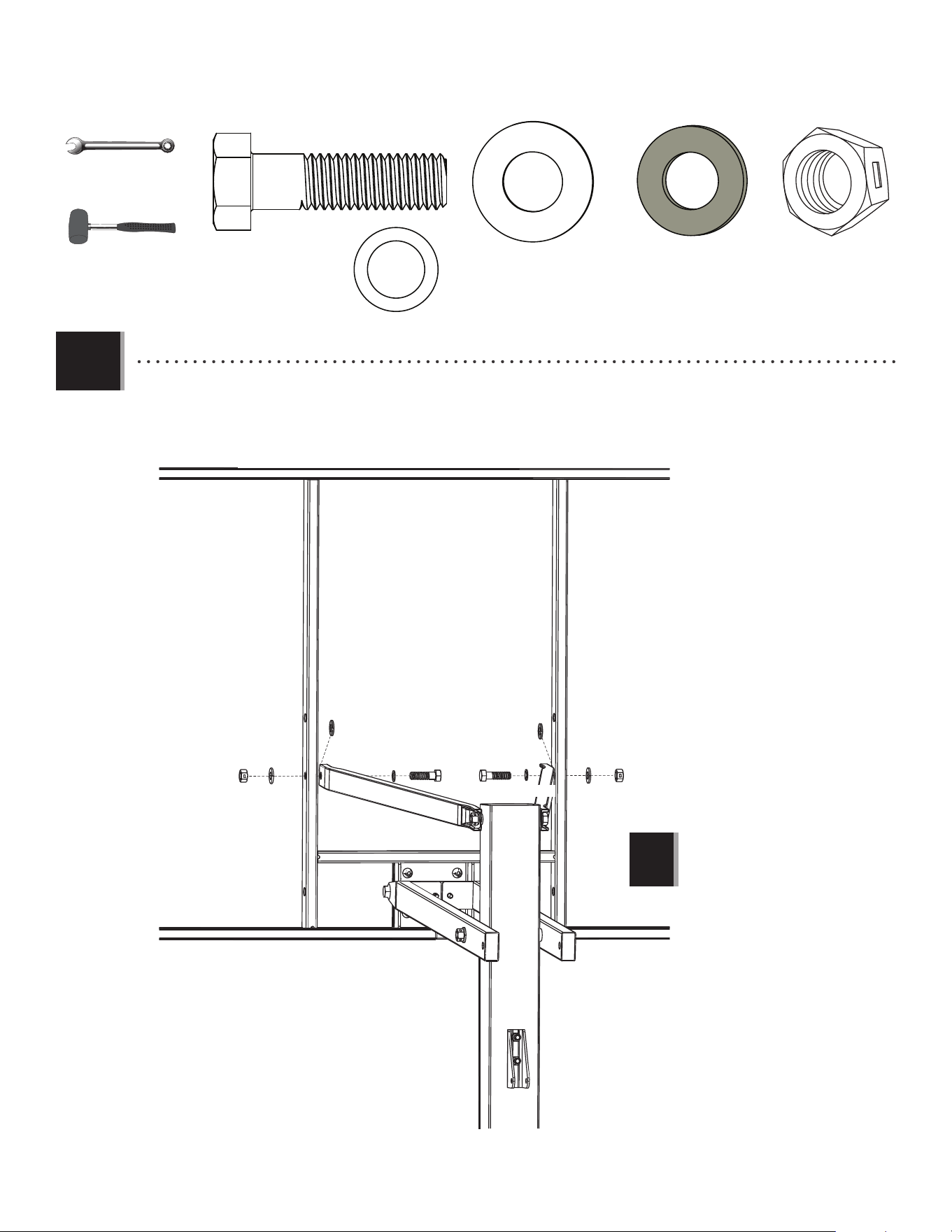
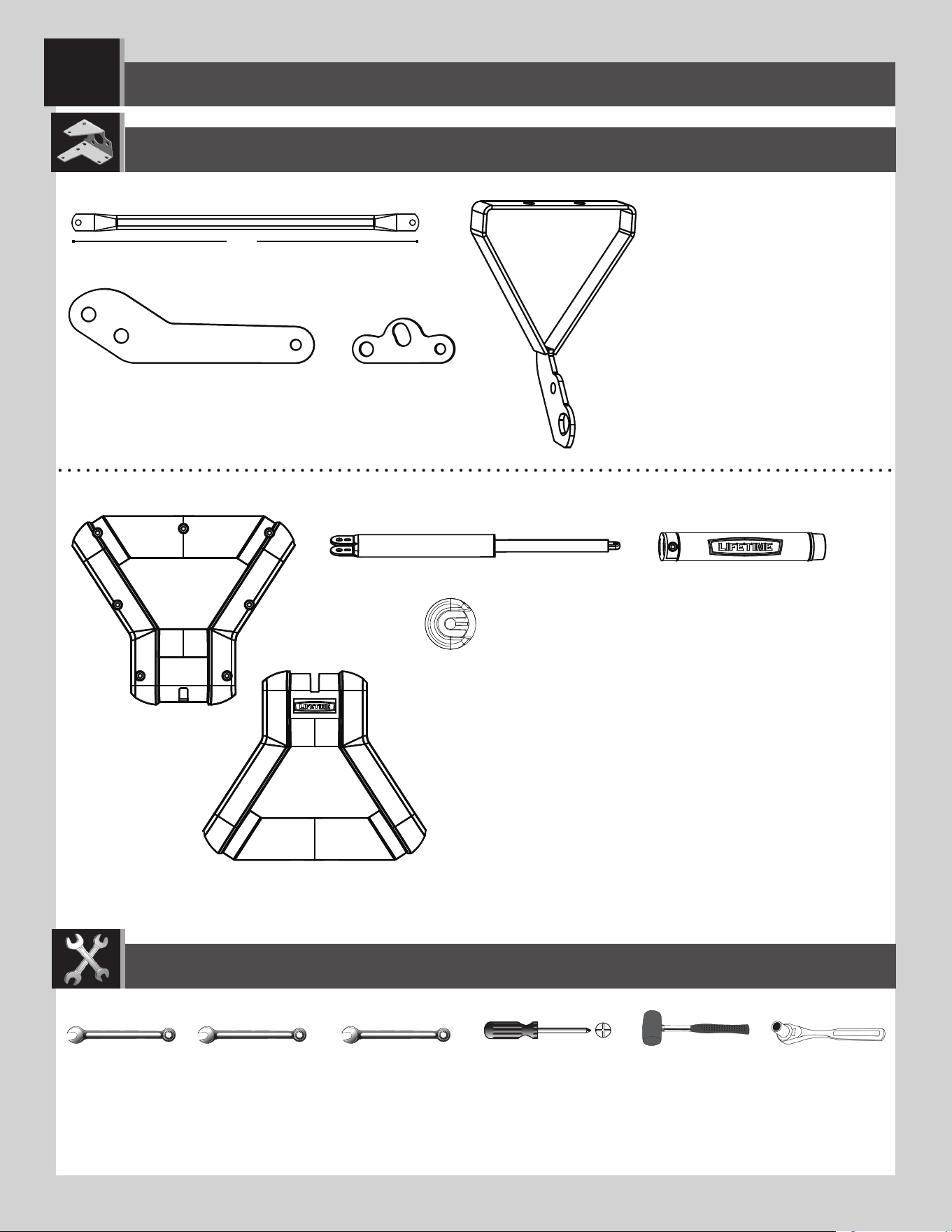
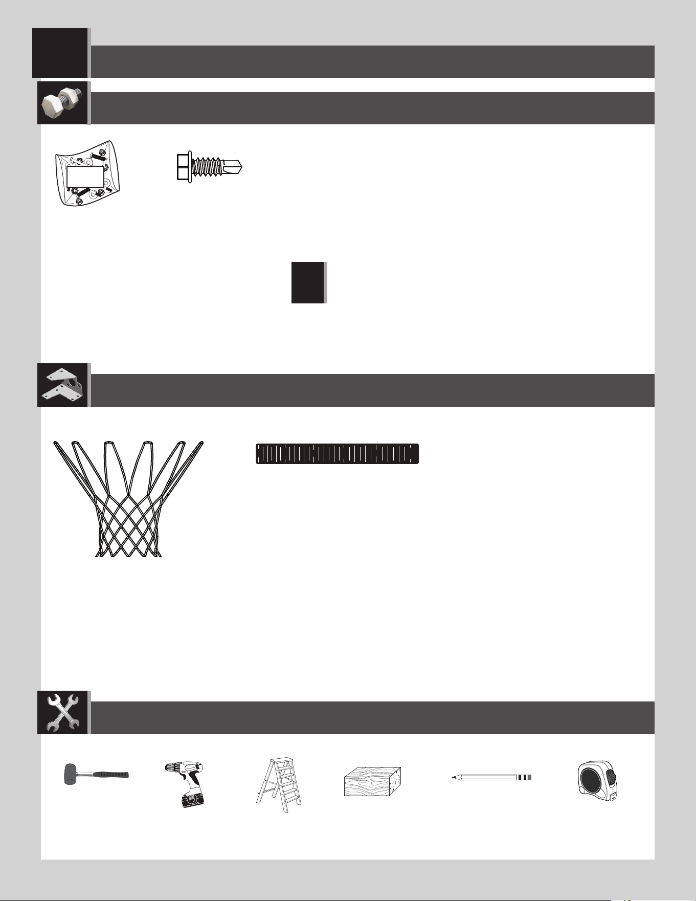
TOOLS REQUIRED
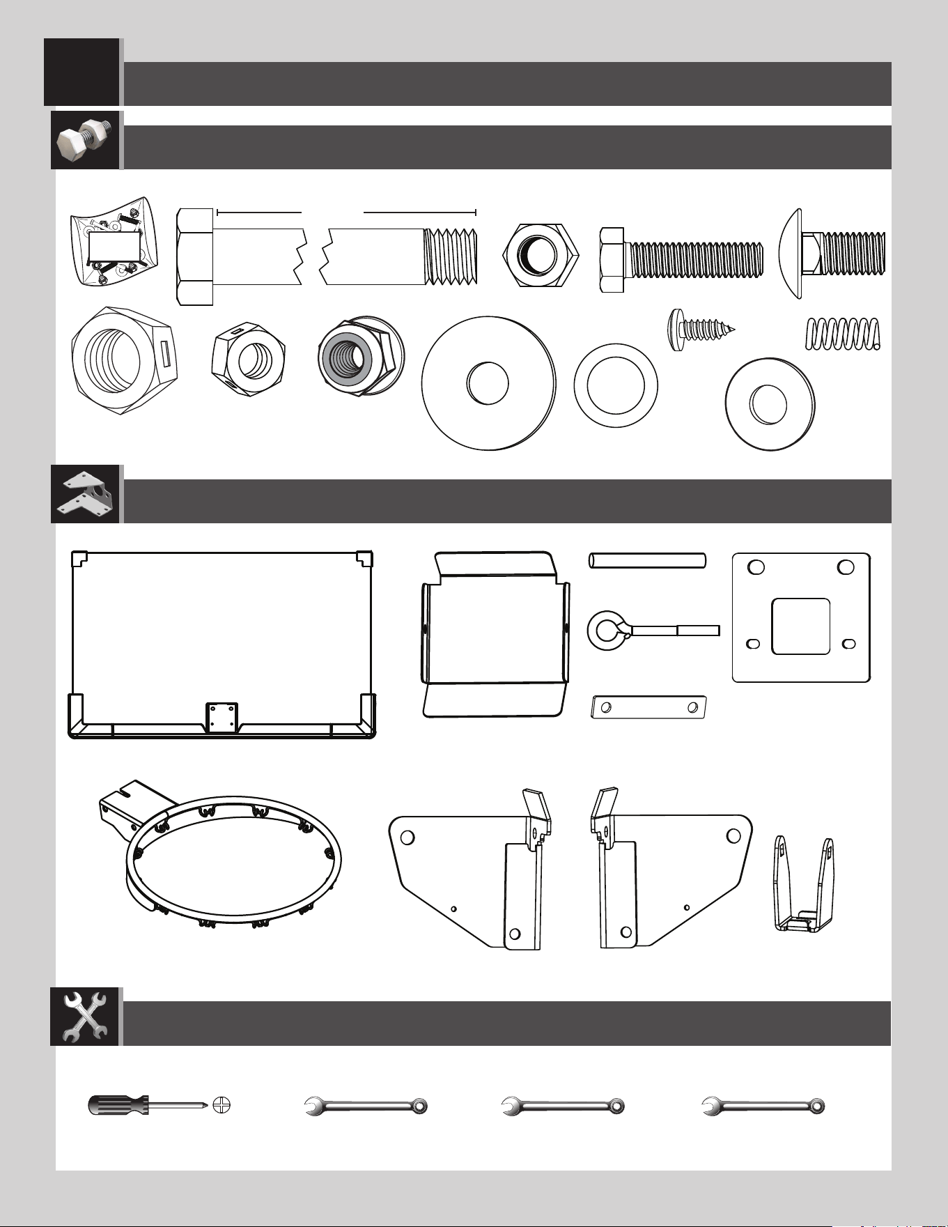
PARTS REQUIRED
HARDWARE REQUIRED
(x1)
(x1)
ALE (x1)
BGW (x1)
Plastic parts
(x1)
(x1)
Concrete mix
640 lb (291 kg)
INITIAL SET UP
(≈4-6)
5
TOOLS AND HARDWARE REQUIRED
SECTION 1 (CONTINUED)
1.1
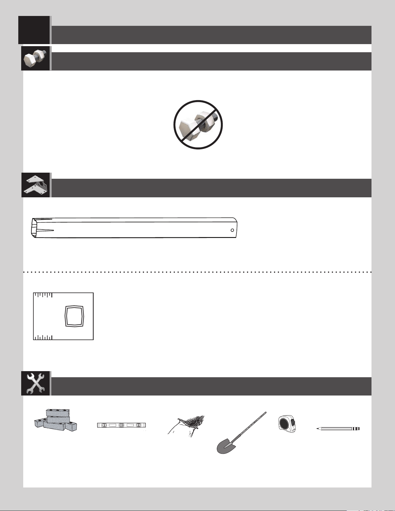
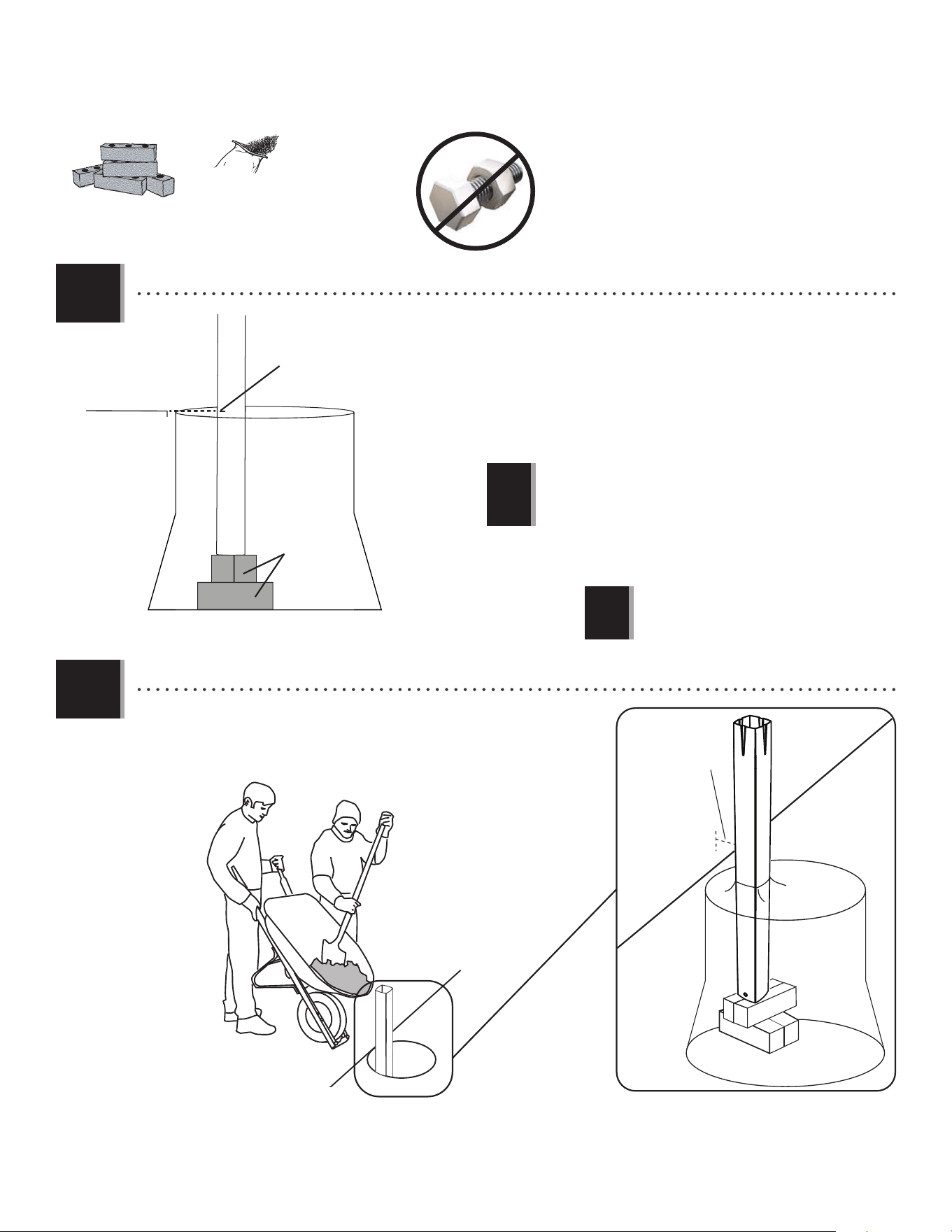
• Dig a round hole 24” (≈61 cm) deep and 21” (≈53 cm) in diameter. If you live in an area where frost heaves may
pose a problem, consult your local building inspector to determine the proper hole depth. The edge of the hole
should be fl ush with the edge of the playing surface.
24 in/po
21 in/po
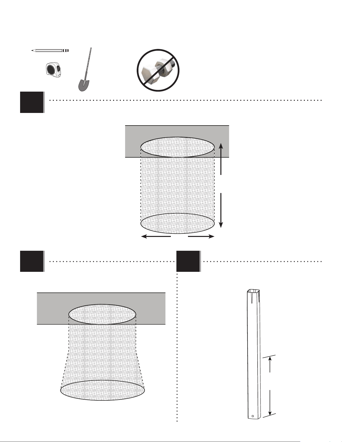
• Widen the bottom diameter about 4” (≈10 cm)
into a bell-shaped hole as shown.
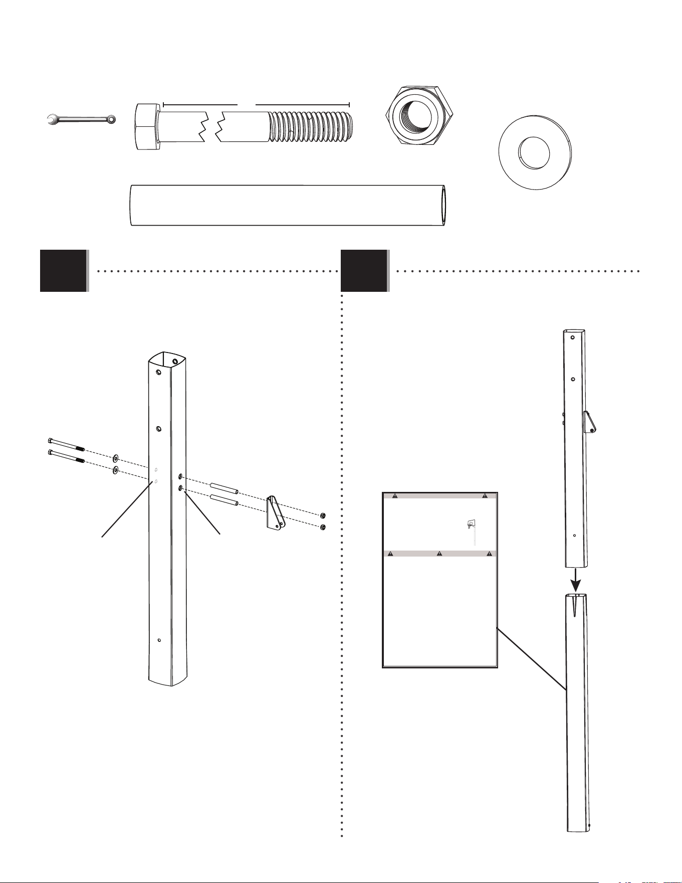
1.2
ALE
16 in/po
(40.6 cm)
• Make a mark 16 inches (40.6 cm) from the
dimpled end of the Bottom Pole (ALE) (do not
scratch the powder coating).
1.3
6
TOOLS AND HARDWARE REQUIRED
SECTION 1 (CONTINUED)
• Stack bricks in the hole for the bottom pole to stand on. Stack enough bricks
in the hole so that the 16-inch (40.6 cm) mark on the pole is even with
the top edge of the playing surface. If the pole is not even with the playing
surface, dig the hole deeper or add more bricks as necessary. Position the
bricks close to the front edge of the hole, near the playing surface. The correct
distance from the basketball court to the front of the pole is 4” (≈10 cm).
1.4
640 lb (291 kg)
• A ground sleeve is available as an
alternative to cementing the pole into the
ground. Please contact Customer Service
for more information.
!
Playing surface
Bricks
16 in. mark
• Mix the concrete. Have one adult hold the bottom pole in place
on the bricks, then pour the mixed concrete into the hole until it is
fi lled to the level of the playing surface.
1.5
Playing surface
4 in/po
• IMPORTANT! If the pole is buried too deep
or too shallow, the rim will not to be at the
correct height.
!
7
TOOLS AND HARDWARE REQUIRED
SECTION 1 (CONTINUED)
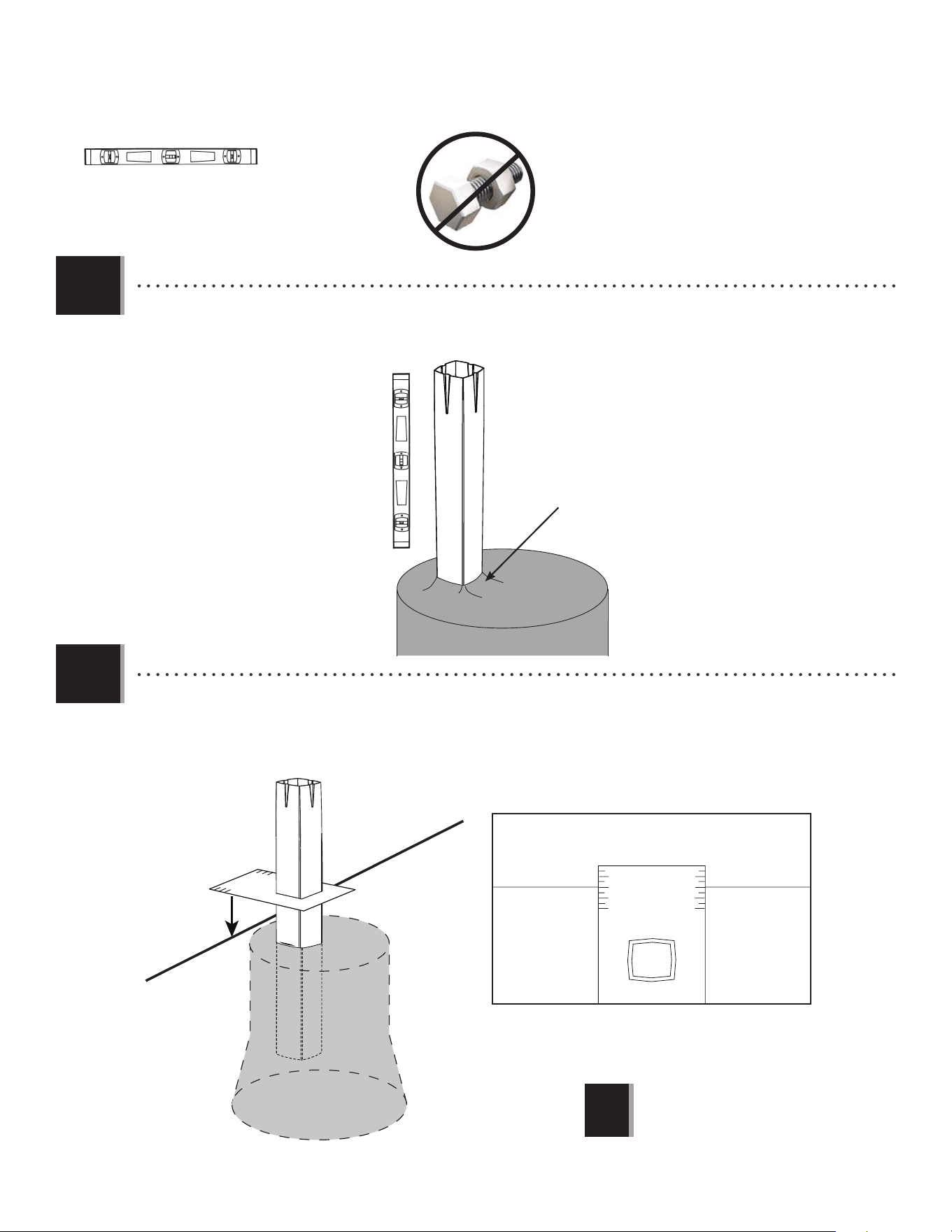
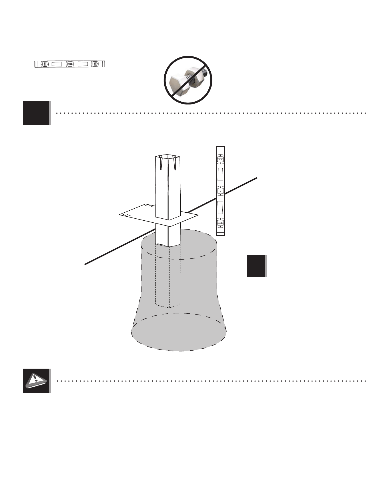
• Slide the paper Alignment Frame (BGW) over the bottom pole. For regulation courts, the alignment frame should
cross the playing surface at the middle of the scored measurements.
1.7
• IMPORTANT! If the pole is buried too deep
or too shallow, the rim will not to be at the
correct height.
!
Playing Surface
ALE
TOP VIEW
BGW
BGW
• Use a level to make sure the bottom pole is standing vertical. Form the cement into a downward slope away from
the pole to allow water runoff. Failure to do so may result in premature rusting of the pole.
1.6
(x1)
Slope
8
TOOLS AND HARDWARE REQUIRED
SECTION 1 (CONTINUED)
!
• Check the pole several times within the fi rst hour to make sure that all sides are vertical and that the 16-inch
mark (40.6 cm) remains level with the surface.
1.8
• STOP ASSEMBLY NOW!
Do not continue the assembly until the concrete has been allowed to set for at least 72 hours (3 days). In humid climates or wet
weather, allow more time for the concrete to cure. Do not proceed until the curing process is complete.
• You may now remove the
alignment frame (BGW).
(x1)
BGW
9
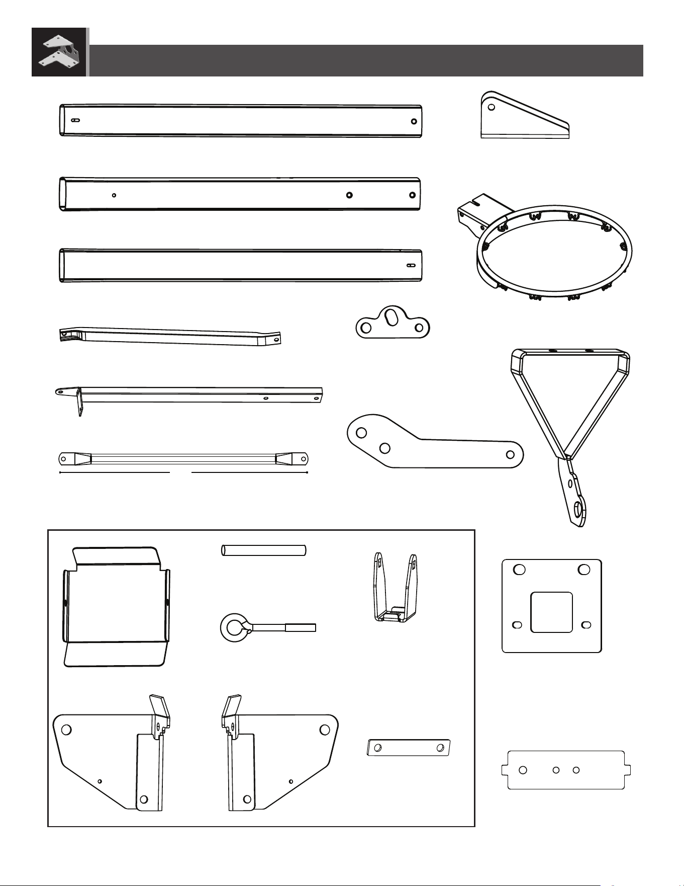
POLE ASSEMBLY
2
BCO
Metal Parts
Hardware Bag
TOOLS REQUIRED
PARTS REQUIRED
HARDWARE REQUIRED
(1)
(1)
9/16"
(≈15 mm)
(1)
(2)
• Warning Sticker applied to this Pole
CMV (x2)*
AAA (x2)
AAF (x2)
ANF (x2)
ANE (x2)
5”
• Only one Self-Drilling Screw (CMV) will
be used in Section 2. Save the second
Screw for use in Section 5.
ALL (x1)
!
ALF (x1)
ALH (x1)
10
TOOLS AND HARDWARE REQUIRED
SECTION 2 (CONTINUED)
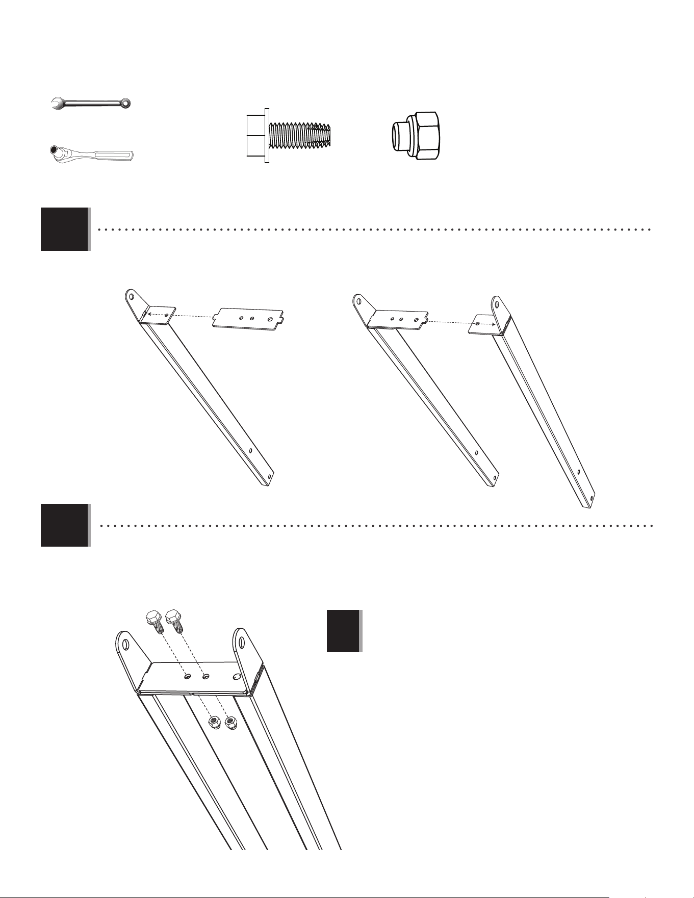
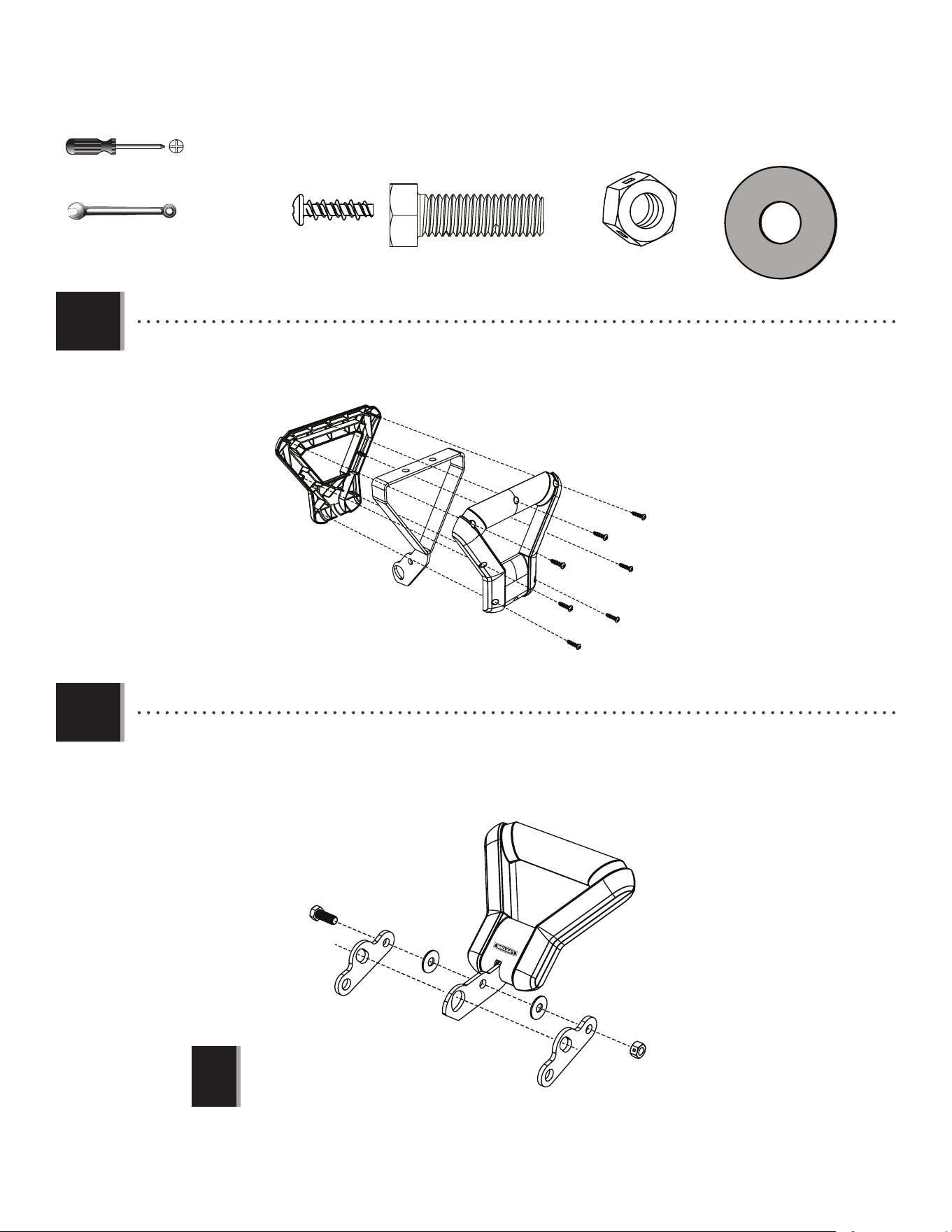
• Secure the Pole Bracket (ALL) to Top Pole (ALH)
with the hardware shown.
2.1
ANE (x2)
ANF (x2)
ALH
ANF
ANE
ALL
AAA
AAF
Large Holes
Small Holes
AAA (x2)
9/16”
(≈15 mm)
(2)
5”
AAF (x2)
ALH
ALF
• Slide the Top Pole over the Middle Pole (ALF). Make
sure the Warning Sticker is on the opposite side of
the assembly as the Pole Bracket.
2.2
FAUTE DE NE PAS SUIVRE CES AVERTISSEMENTS, VOUS RISQUEZ DE CAUSER
DES BLESSURES GRAVES ET/OU DES DOMMAGES À L’ÉQUIPEMENT.
Le propriétaire doit s’assurer que tous les joueurs con-
naissent et appliquent les règles suivantes afin d’utiliser
l’équipement en toute sécurité.
SI NO SE OBEDECEN ESTAS ADVERTENCIAS PUEDEN PRODUCIRSE
GRAVES LESIONES Y/O DAÑOS A LA PROPIEDAD.
El propietario del sistema debe asegurarse de que todos
los jugadores conozcan y respeten estas reglas para que el
sistema se use en forma segura.
WARNING
FAILURE TO FOLLOW THESE WARNINGS MAY RESULT IN SERIOUS INJURY
AND/OR PROPERTY DAMAGE.
Owners must ensure that all players know and follow these
rules for safe operation of the system.
• Only hang from the Rim briefly to regain balance or avoid
injuring others. Release the Rim as soon as safely possible.
• During play, especially when performing dunk type activities,
keep player’s face away from the Backboard, Rim, and Net.
Serious injury could occur if teeth/face come in contact with
the Backboard, Rim, or Net. Player should wear a mouth
guard during play.
• Do not slide, climb, or play on Base or Pole.
• When adjusting height or moving system, keep hands and
fingers away from moving parts.
• Do not allow children to move or adjust system.
• Do not wear jewelry (rings, watches, necklaces, etc.) during
play. Objects may entangle in Net.
• Keep water and organic material away from Pole Base. Grass,
litter, etc. could cause corrosion and/or deterioration.
• Never play on damaged equipment.
• Once a month check Pole and all metal parts for signs of
corrosion (rust, pitting, chipping). Completely remove rust and
repaint with exterior enamel. If rust has penetrated any steel
part, replace that part immediately.
• Check system before each use for proper ballast, loose
hardware, excessive wear, instability, and signs of corrosion
and repair before use.
• Do not use the system to lift or hoist anything. The
mechanism is designed to lift only the weight of the
Backboard and Rim. Do not hang anything from the Handle,
Rim, Backboard, or Lifter Arms as this will damage the
system and void the warranty.
• Ne vous suspendez pas à l’anneau plus que nécessaire pour
retrouver votre équilibre ou éviter de blesser les autres joueurs.
Relâchez l’anneau aussitôt que possible.
• Lors d’un match, particulièrement dans le cas des smashs, le
visage du joueur ne doit pas faire face au panneau, à l’anneau, ni au
filet. Le joueur risque de graves blessures si ses dents ou son visage
entrent en contact avec le panneau, l’anneau, ou le filet. Les joueurs
doivent toujours porter un protège-dents lorsqu’ils jouent.
• Ne glissez pas, ne grimpez pas, et ne jouez pas sur la base ou le
poteau.
• Lorsque vous ajustez la hauteur ou lorsque vous déplacez
l’équipement, gardez vos mains et doigts loin des pièces mobiles.
• Ne permettez pas aux enfants de déplacer ou d’ajuster
l’équipement.
• Ne portez pas de bijoux (bagues, montres, colliers, etc.) lorsque
vous jouez. Ces objets pourraient s’accrocher au filet.
•Gardez de l’eau et de la matiére organique loin de la base. Le
gazon, les déchets, etc. pourraient provoquer la corrosion et/ou la
détérioration.
• Une fois par mois, vérifiez que le Poteau et toutes les pièces en
métal ne montrent pas de signes de corrosion (rouille, piqûres,
écaillage). Enlevez toute la rouille et repeignez complètement avec
une peinture pour extérieur. Si la rouille a pénétré une des pièces en
acier, vous devrez remplacer immédiatement la pièce en question.
• A chaque fois que vous allez utiliser l’équipement, vérifiez d’abord
l’équilibre, la possibilité de pièces desserrées ou usées, la stabilité
de l’équipement et tout signe de corrosion ou réparation nécessaire
avant utilisation.
• Ne jouez jamais avec un équipement endommagé.
• N’utilisez pas l’équipement pour lever ou soulever quoique ce soit.
Son mécanisme a été conçu uniquement pour soutenir le poids du
panneau et de l’anneau. N’accrochez rien au manche, à l’anneau,
au panneau ni aux leviers sous peine d’endommager l’équipement
et d’annuler la garantie.
• Cuélguese del aro sólo en forma breve, para recuperar el equilibrio
o evitar lesionar a otros jugadores. Suéltese del aro lo más pro nto
que pueda hacerlo con seguridad.
• Durante el juego, e specialmente al embocar violentamente de
alto, la cara de los jugadores debe mantenerse alejada del tablero,
el aro y la red. Pueden producirse lesiones graves si los dientes o la
cara entran en contacto con el tablero, el aro o la red. Los jugadores
deben usar un protector bucal durante el juego.
• No se deslice, no trepe ni juegue sobre la base o el poste.
•Mantenga las manos y los dedos alejados de las piezas movibles
cuando regule la altura o desplace el sistema.
• No deje que los niños regulen ni desplacen el sistema.
• No use joyas (anillos, relojes, collares o gargantillas, etc.) durante el
juego. Estos objetos pueden engancharse en la red.
• Guarde aqua y materia orgánica. Céspe d, basura,etc., prodrian
causar corrosión et/o deterioros.
• Co ntrole el poste y todas las piezas metálicas una vez al mes
en busca de signos visibles de corrosión (oxidación, picaduras,
escamado). Elimine todo rastro de óxido y vuelva a pintar con
esmalte para exteriores. Si el óxido ha penetrado cualquier pieza de
acero, reemplace esa pieza de inmediato.
• Inspeccione el sistema antes de cada uso para verificar que esté
adecuadamente contrapesado, que los elementos de fijación no
estén flojos, que no haya desgaste excesivo, inest abilidad ni signos
de corrosión. Si encuentra irregularidades, repárelas antes de usar
el sistema.
• Nunca juegue con un equipo dañado.
•No use el sistema para levantar ningún objeto. El mecanismo está
diseñado para elevar solamente el peso del tablero con el aro. No
cuelgue nada de la agarradera, el aro, el tablero ni los brazos de
elevación, ya que esto puede dañar el sistema y anular la garantía.
www.lifetime.com
# 1176611
ADVERTENCIAAVERTISSEMENT
Lifetime Products, Inc., Clearfield, UT 84016
1-800-225-3865
7/12/2016
11
TOOLS AND HARDWARE REQUIRED
SECTION 2 (CONTINUED)
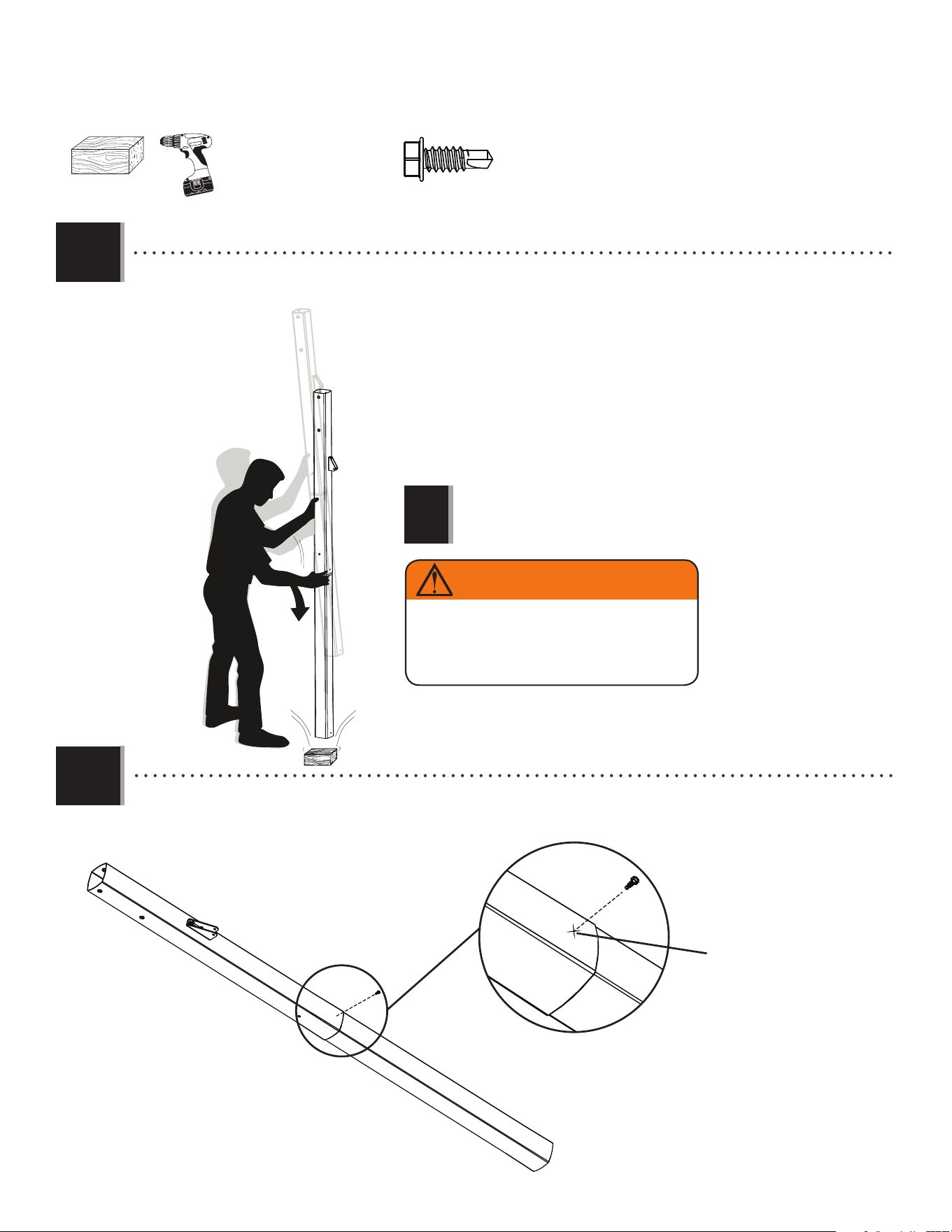
2.3
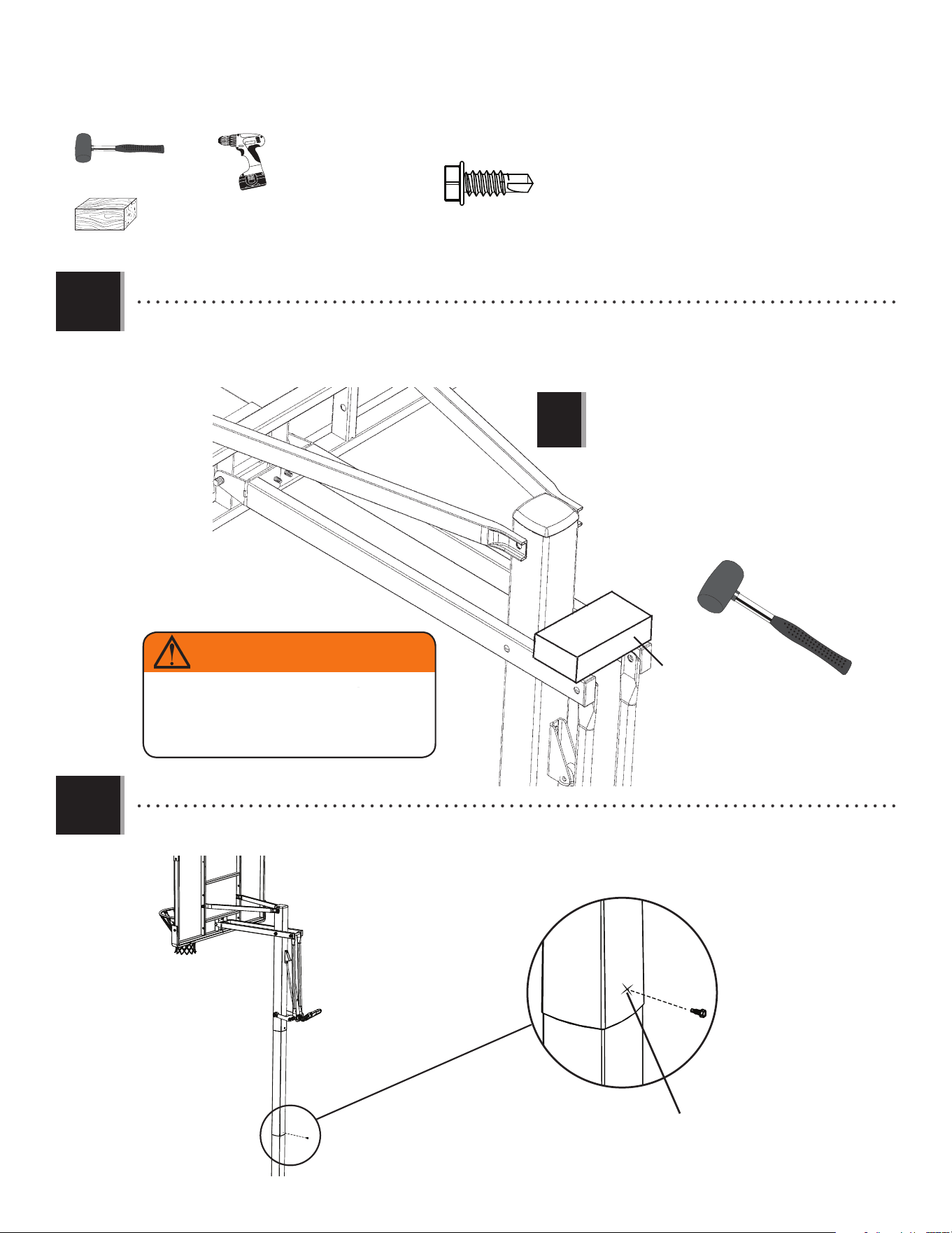
• Do not hit your feet with the Pole
sections, as serious injury could
occur.
(1)
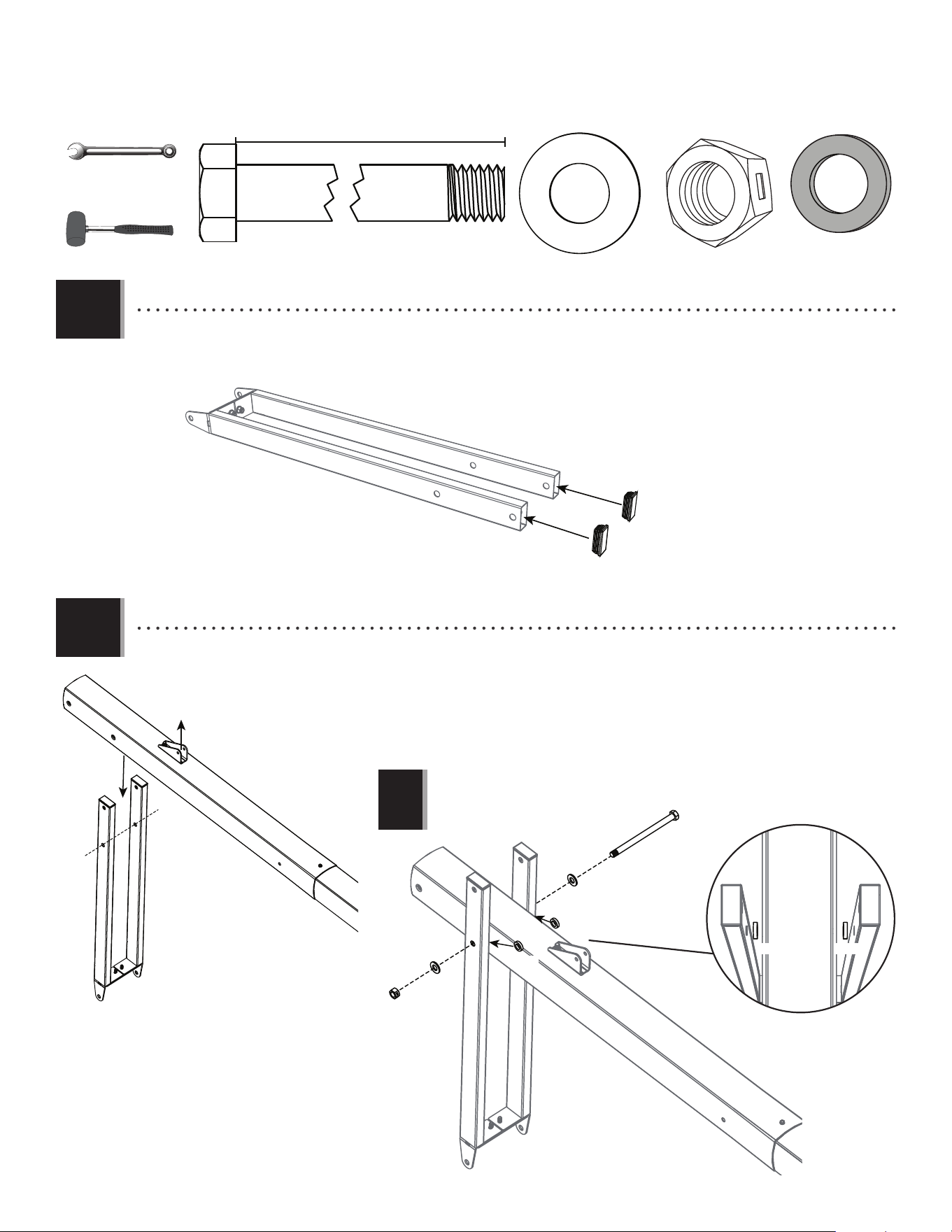
• THIS STEP CANNOT BE REVERSED! Strike the end of the Pole Assembly on a piece of scrap wood or
cardboard fi ve to six times.
6x
!
(1)
CMV (x1)
CMV
ALH
ALH
ALF
1" up from bottom of
Top Pole
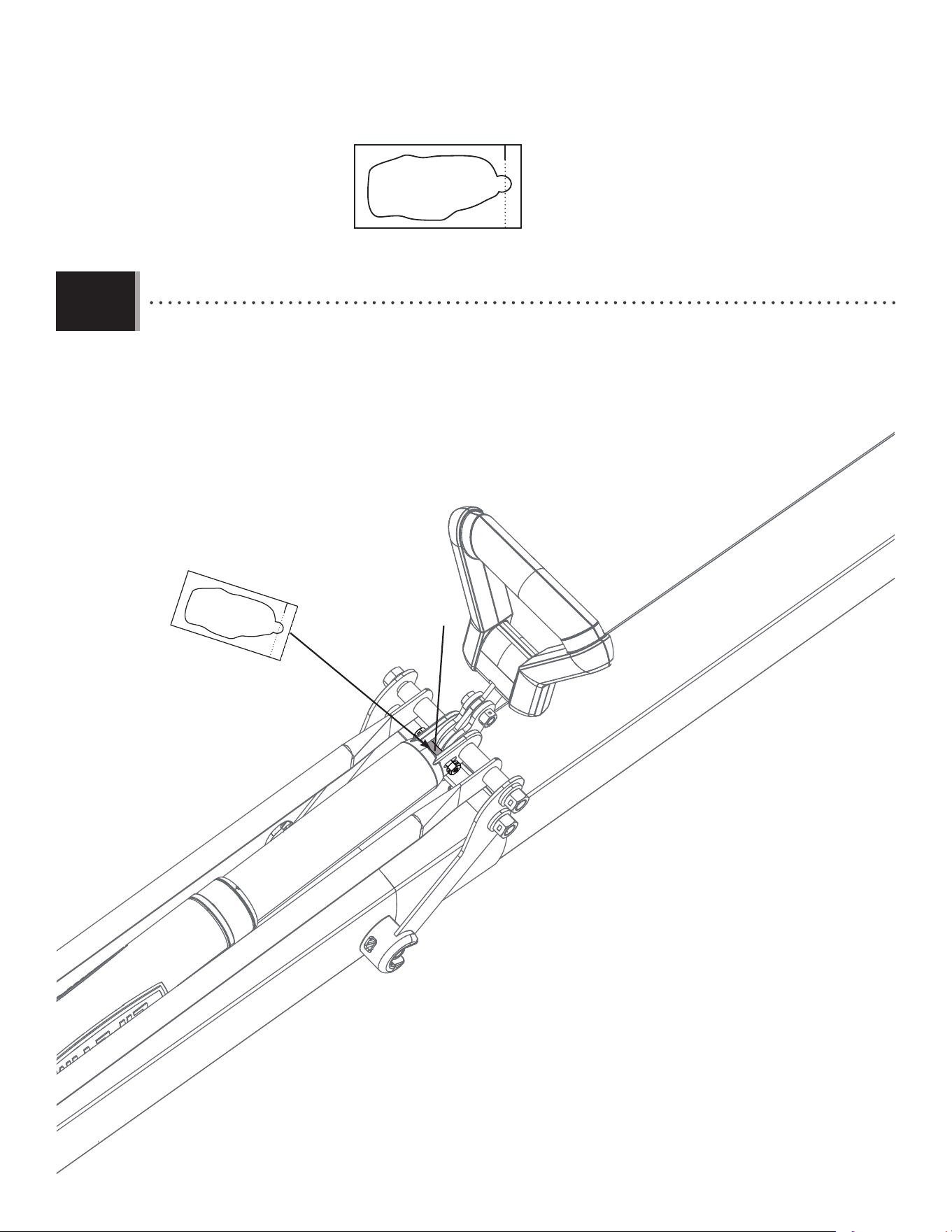
• After the Poles have been seated, measure up 1" from the bottom center of the Top Pole (ALH) and insert one
Self-Drilling Screw (CMV) into the Pole as shown.
2.4
WARNING
The Poles must be seated together! Poles must
be struck on a hard surface five to six times!
Failure to seat the Poles correctly could allow the
Poles to separate during use, which could lead
to serious personal injuries or property damage.
12
BACKBOARD TO RIM ASSEMBLY
3
BCS
Hardware Bag
PARTS REQUIRED
HARDWARE REQUIRED
AJI (x1)
Metal Parts
ANK (x4)
ABK (x4)
ADX (x2)
BGZ (x1)
ANL (x1)
5 9/16”
AAX (x1)
ANO (x1)
ABD (x4)
ANM (x2)
ABB (x2)
ANN (x2)
ANJ (x4)
AMB (x1)
AMA (x1)
BGY (x1)
AMC (x1)
AMK (x1)
ALY (x1)
BPZ (x1)
BQA (x1)
ALX (x1)
TOOLS REQUIRED
1/2" (13 mm) 9/16" (14 mm) 3/4" (19 mm)
(x1)
(x2) (x2) (x2)
13
SECTION 3 (CONTINUED)
TOOLS AND HARDWARE REQUIRED
ANJ (x2)
ABD (x2)
ABK (x2)
3.1
• The Glass Backboard will break if the Rim
Spacer (BGY) is not installed as shown in this
step. This may result in personal injury or
property damage.
!
ANJ
ANJ
ABD
ABD
AMB
AMC
BGY
AJI
ABK
ABK
• Lay the Backboard (AJI) face up with the Rim holes exposed over the edge of a table. Place the Rim Impact Spacer
(BGY) in the Backboard. Add the Left and Right Rim Housings (AMC & AMB) on top of the Rim Impact Spacer and slide
the hardware shown into place.
9/16" (14 mm)
(x2)
14
SECTION 3 (CONTINUED)
TOOLS AND HARDWARE REQUIRED
3.2
3.3
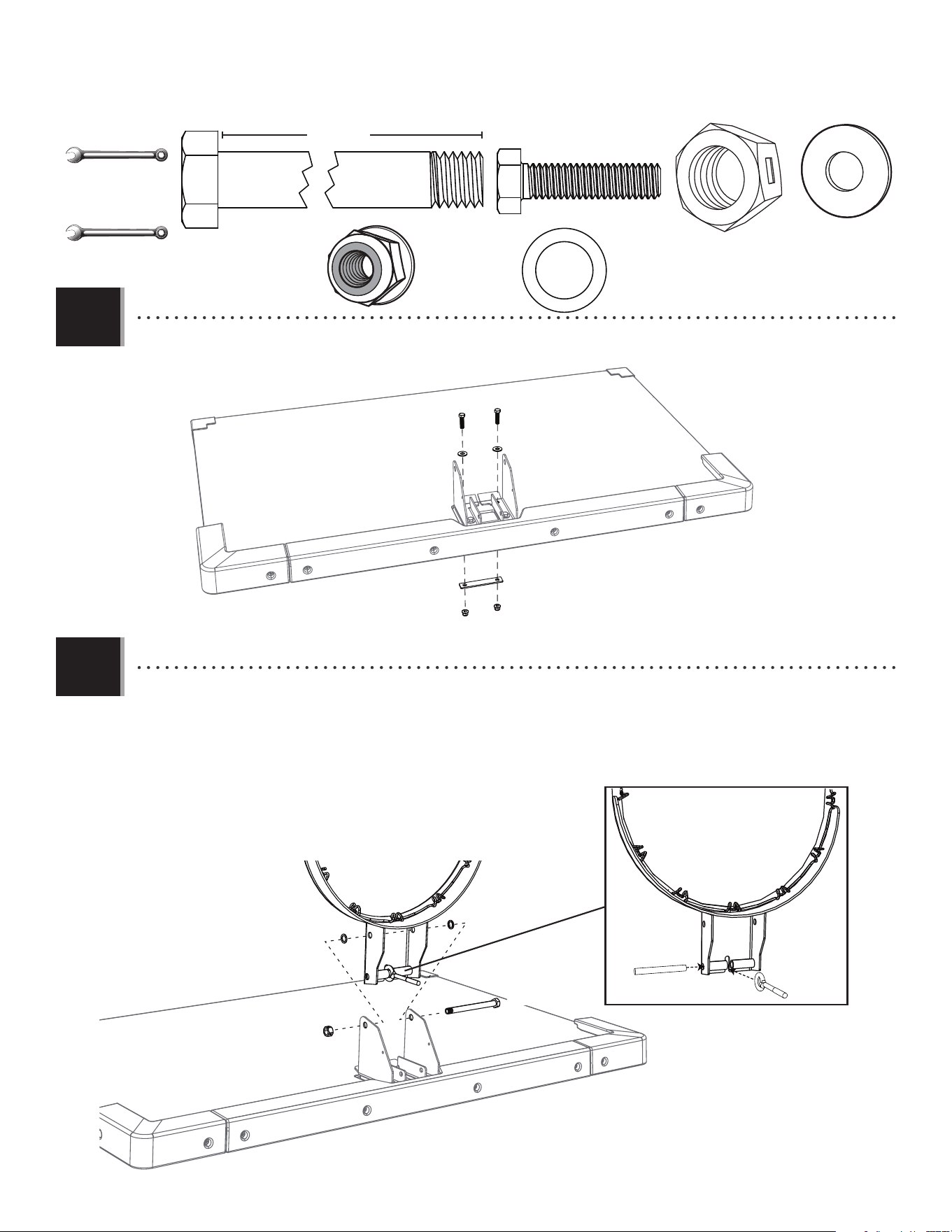
• Secure the Rim Adapter Plate (ALY) to the Backboard (AJI) by using the hardware as shown.
• Slide the end of the Rim Pin (BPZ) into the Rim (ALX) and through the Eye Bolt (BQA) in the location indicated. Attach
the Rim to the Rim Housing using the hardware shown, making sure the Nylon Washers (ANK) rest between the Rim
and the Rim Housing.
ANJ (x2)
ABD (x2)
ABK (x2)
ABD
ABD
ANJ
ANJ
ALY
ABK
ABK
AJI
BPZ
BQA
ALX
ANK
ANK
ANL
AAX
5 9/16”
ANL (x1)
AAX (x1)
ANK (x2)
1/2" (13 mm)
(x2)
3/4" (19 mm)
(x2)
15
SECTION 3 (CONTINUED)
TOOLS AND HARDWARE REQUIRED
ANM (x2)
ABB (x2)
ALX
BQA
AMK
ANK (x2)
ANM
ANM
ABB
ABB
3.4
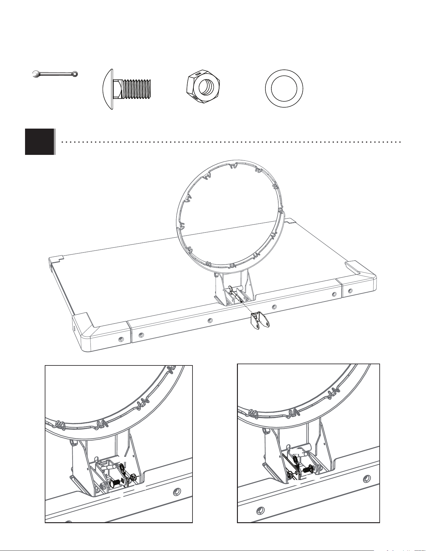
• Slide the Spring Holder Clevis (AMK) onto the Eye Bolt (BQA) and secure with the hardware shown.
ANK
ANK
9/16" (14 mm)
(x2)
16
SECTION 3 (CONTINUED)
TOOLS AND HARDWARE REQUIRED
3.5
3.6
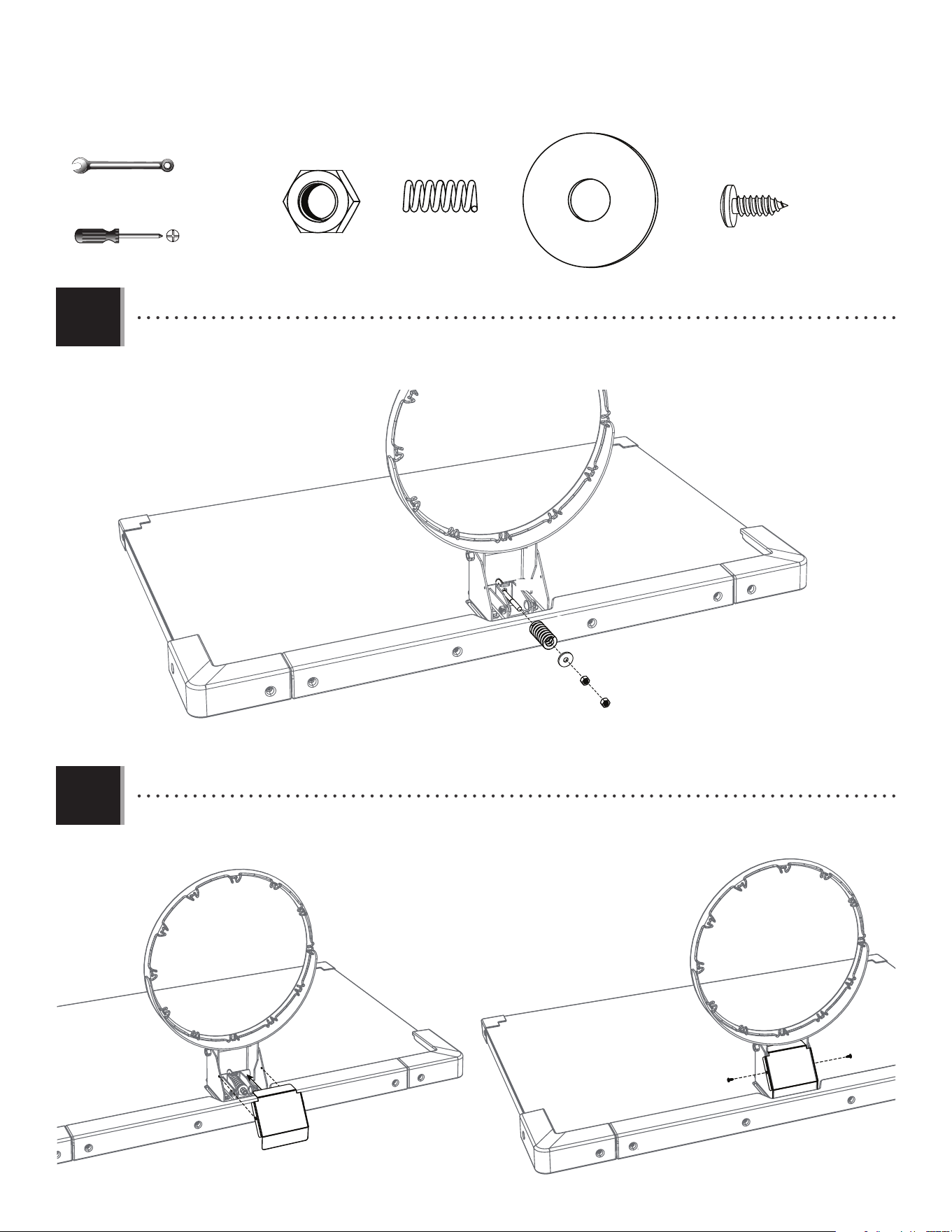
• Slide the Compression Spring (BGZ) onto the Eye Bolt (BQA), and secure with the hardware shown. Tighten the 3/8” Zinc
Nuts (ANN) to adjust Rim tension.
• Attach the Rim Cover Plate (AMA) to the Rim with the hardware shown.
BQA
ANN
ANN
ANN (x2)
ANO
BGZ (x1)
ANO (x1)
BGZ
ADX (x2)
AMA
ADX
ADX
(x1)
9/16" (14 mm)
(x2)
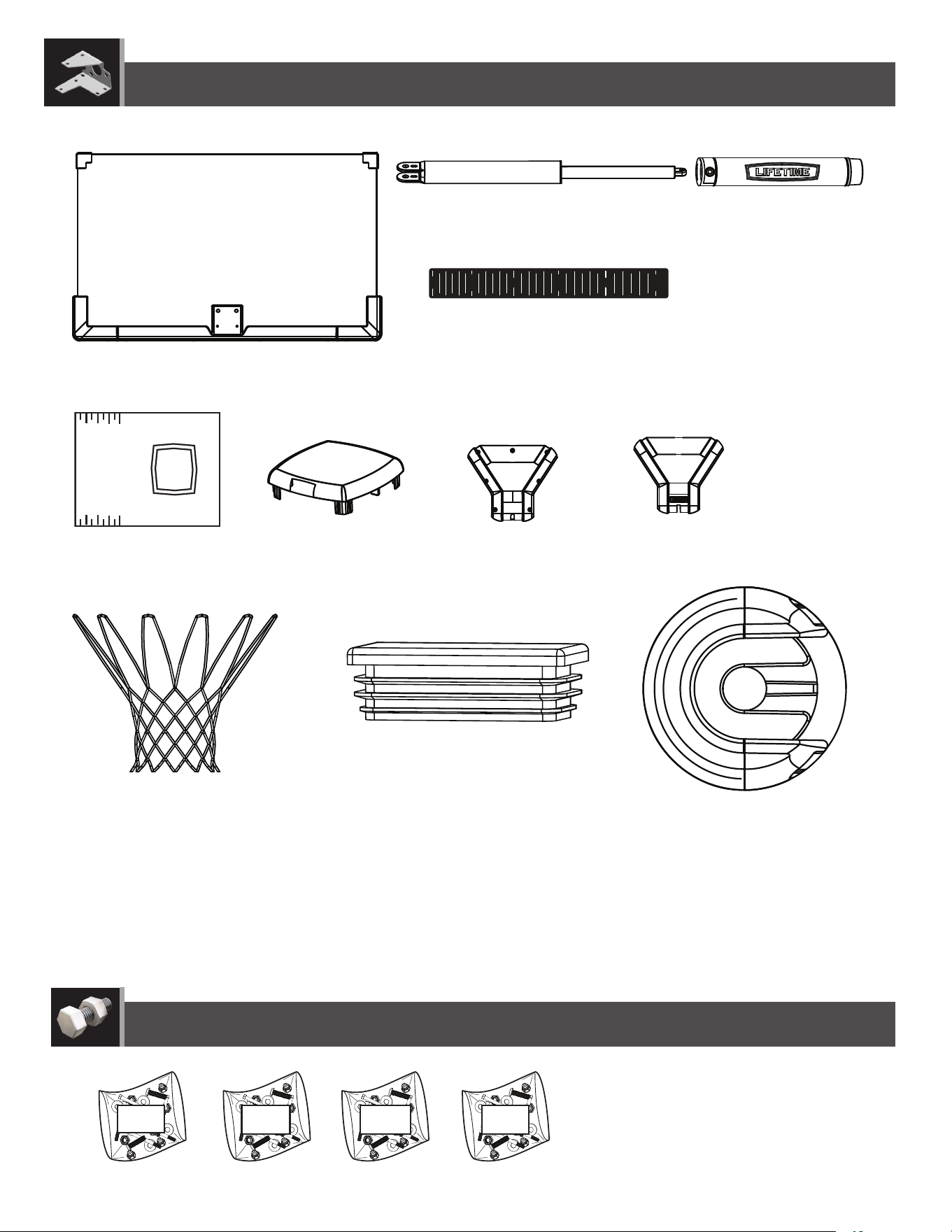
17
Metal Parts
Hardware Bag
TOOLS REQUIRED
PARTS REQUIRED
HARDWARE REQUIRED
BACKBOARD TO POLE ASSEMBLY
4
(x1) (x2)
(x1) (x1)
1/2"
(≈13 mm)
1/2" (≈13 mm)
3/4" (≈19 mm)
11/16" (≈18 mm)
(x1)
BCR
AAD (x1)
ANQ (x2) AQD (x1)
ANU (x2)
AQB (x2)
ANS (x8)
AAN (x2)
AAX (x4)
5”
ANP (x1)
AOR (x6)
ABP (x2)
ANK (x4)
AQC (x2)
BGP (x2)
BGO (x2)
BLC (x1)
ANZ (x2)
ABN (x4)
ALM (x1)
Plastic Parts
7 1/16" (17,9 cm)
18
SECTION 4 (CONTINUED)
TOOLS AND HARDWARE REQUIRED
4.1
• Insert one end of the Tie Plate (BLC) into the slot on the Lower Extension Arm (BGP), then insert the opposite end of the
Tie Plate (BLC) into the slot on the other Lower Extension Arm (BGP) as shown.
• Do not overtighten the Cap Nut. If the end of the Bolt breaks
through the plastic cap, call our Customer Service Department.
Exposed threads on the end of the Bolt may cause serious injuries.
!
1/2” (≈13 mm)
(x1)
1/2”
(≈13 mm)
(x1)
BLC
BLC
BGP
BGP
AQB
AAN
BGP
BGP
BLC
AQB (x2)
AAN (x2)
4.2
• Secure the Lower Extension Arms (BGP) together with the hardware shown. Use a 1/2” Socket Wrench to screw the Thread-
Cutting Bolts (AQB) through the Lower Extension Arms and the Tie Plate (BLC).
19
SECTION 4 (CONTINUED)
TOOLS AND HARDWARE REQUIRED
4.3
TOOLS AND HARDWARE REQUIRED / HERRAMIENTAS Y ACCESORIOS REQUERIDOS / OUTILS ET ACCESSOIRES REQUIS
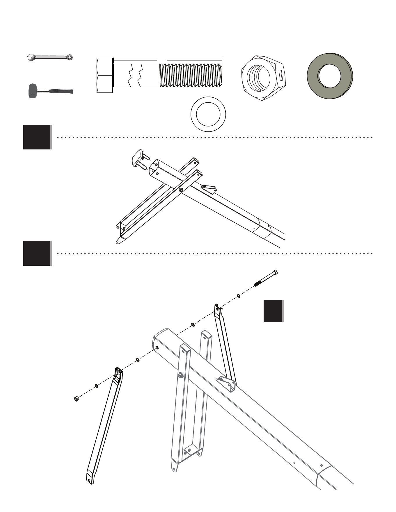
• Insert the Extension Arm Caps (AQC) into the ends of the Lower Extension Arms (BGP) as shown.
SECTION 4 (CONTINUED)
• Place the Top Pole (ALH) to the Lower Extension Arms (BGP) and secure them with the hardware shown.
4.4
BGP
BGP
AQC
AQC
BGP
AAX
AAD
AOR
AOR
ANZ
ANZ ANZ
ANZ
ALH
• Tighten the Nut until it is
fl ush with the end of the Bolt.
!
AAX (x1)
AAD (x1)
3/4" (≈19 mm)
(x2)
ANZ (x2)
AOR (x2)
20
SECTION 4 (CONTINUED)
TOOLS AND HARDWARE REQUIRED
AAX (x1)
4.6
• Attach the Upper Extension Arms (BGO) to the Top Pole (ALH) with the hardware as shown.
3/4"
(≈19 mm)
(x2)
5”
BGO
BGO
AQD
AAX
ANK
ABN
ABN
ANK
AQD (x1)
ANK (x2)
• Tighten the Nut until it is fl ush
with the end of the Bolt.
!
ABN (x2)
(x1)
4.5
• Insert the Pole Cap (ALM) into the Top Pole as shown. Line up the Pole Cap stirrups with the holes in the top of the Pole.
ALM
21
SECTION 4 (CONTINUED)
TOOLS AND HARDWARE REQUIRED
4.7
ANP (x1)
ABP (x2)
AOR (x2)
ANQ (x2)
BGP BGP
AJI
ANQ
ANQ
AOR
AOR
ANP
ABP
ABP
ABP
AOR
AOR
ANQ ANQ
ANP
3/4" (≈19 mm)
(x2)
11/16"
(≈18 mm)
(x1)
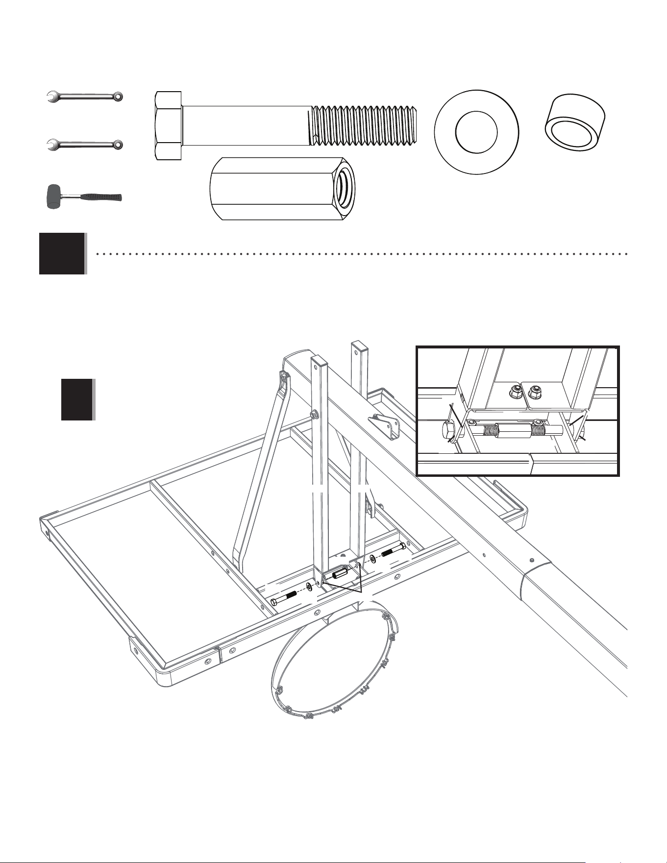
• Rest the Rim on cardboard to prevent scratching, then secure the Lower Extension Arms (BGP) to the Backboard (AJI)
with the hardware shown. Thread the Nut Coupler (ANP) onto one of the Hex Bolts (ANQ), then onto the other. Center
the coupler between the two Bolts as shown.
• Make sure the Poly Spacers (ABP) positioned
between the Lower Extension Arms and the
Backboard do not bulge.
!
(x1)
22
SECTION 4 (CONTINUED)
TOOLS AND HARDWARE REQUIRED
4.8
AOR (x2)
ANK (x2)
ANU (x2)
AAX (x2)
• Attach the Upper Extension Arms (BGO) to the Backboard (AJI) with the hardware as shown.
3/4"
(≈19 mm)
(x2)
ABN (x2)
AAX
AAX
AOR
AOR
ANK
ANK
ANU
ANU
BGO
BGO
ABN
ABN
• Tighten the Nuts until they are
fl ush with the end of the Bolts.
!
(x1)

i
This page intentionally left blank
Lift out this section for use as a quick reference
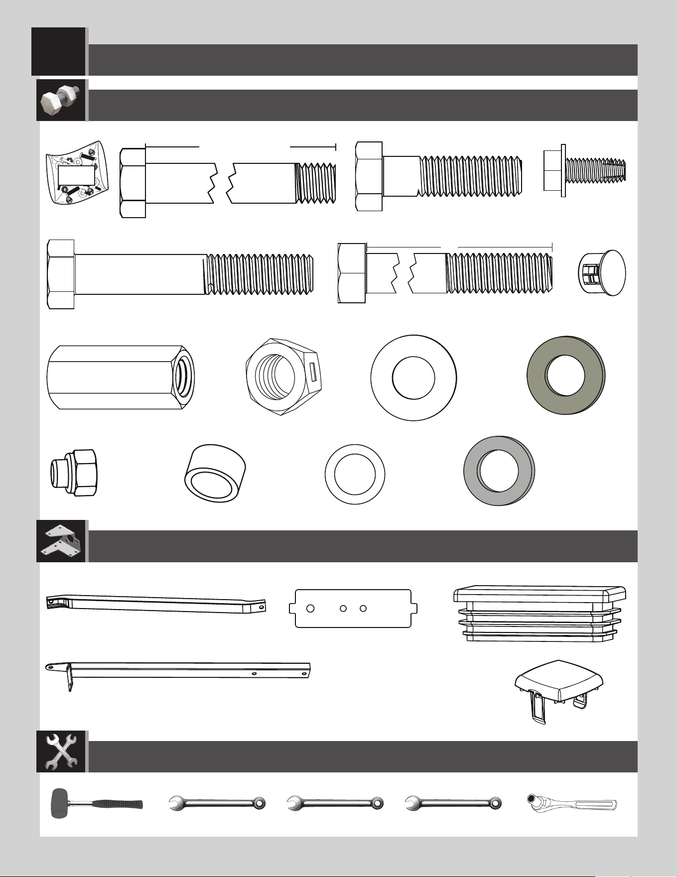
PARTS IDENTIFIER
ii
PARTS IDENTIFIER
Metal Parts
ALE (x1)
• Warning Sticker applied to side not shown
ALH (x1)
ALF (x1)
ALL (x1)
ALX (x1)
AMB (x1)
AMA (x1)
BGY (x1)
AMC (x1)
AMK (x1)
BPZ (x1)
BQA (x1)
BGP (x2)
BGO (x2)
BLC (x1)
ALS (x2)
31”
CKJ (x1)
CKM (x2)
CMR (x2)
ALY (x1)
Metal Parts found in Rim Kit
Lift out this section for use as a quick reference
iii
PARTS IDENTIFIER
HARDWARE REQUIRED
Plastic Parts
BCO
BCS BCR BCT
BGW (x1)
ALM (x1)
AJI (x1)
AKZ (x1)
AKF (x1)
CKH (x1)
CKI (x1)
AKG (x1)
CKG (x2)
AKP (x1)
AQC (x2)
1109 02 5
10’
9’6”
9’
8’6”
7’6”
8’
Lift out this section for use as a quick reference

iv
This page intentionally left blank
PARTS IDENTIFIER
Lift out this section for use as a quick reference
23
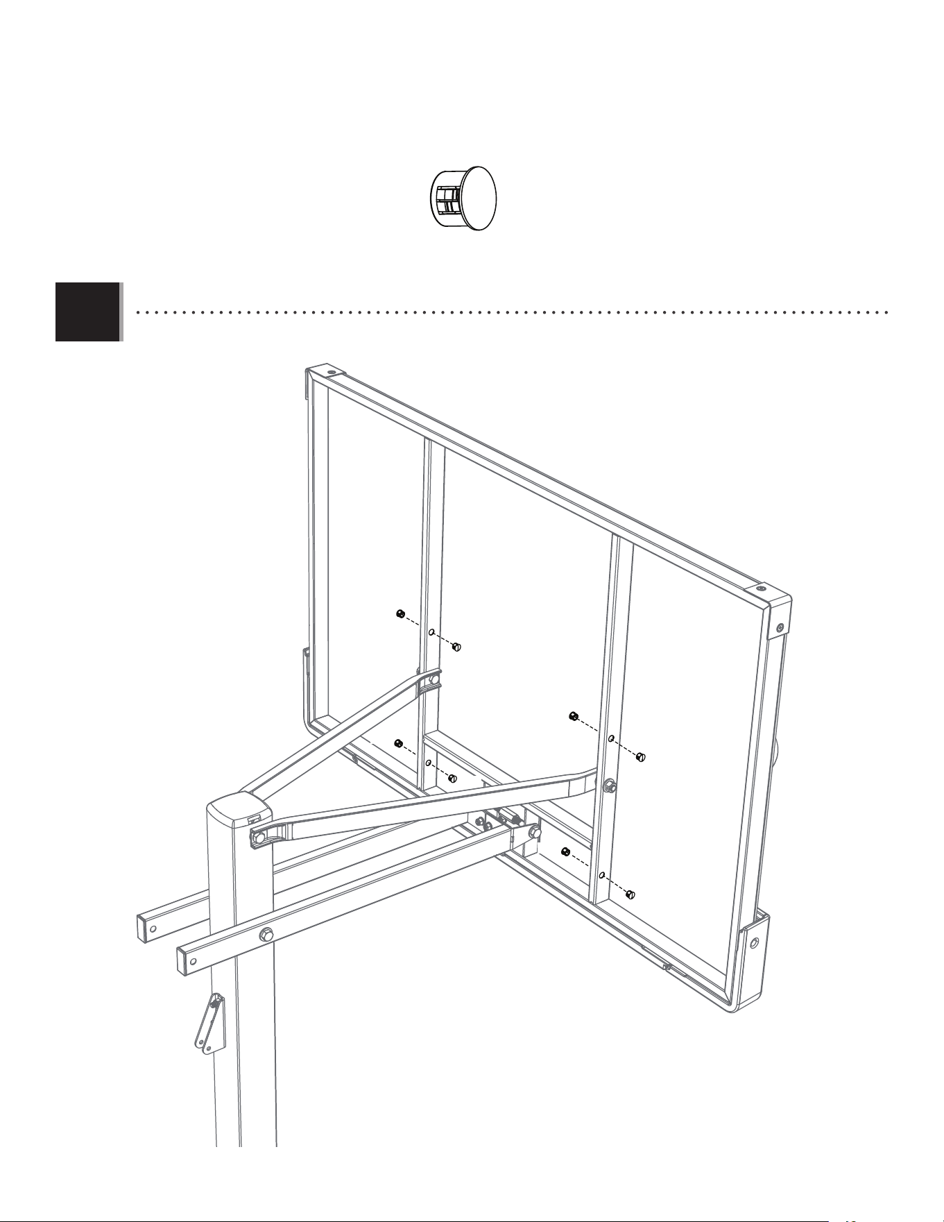
SECTION 4 (CONTINUED)
TOOLS AND HARDWARE REQUIRED
4.9
• Insert Nylon Plugs (ANS) into the locations indicated on the frame of the Backboard.
ANS (x8)
ANS
ANS
ANS
ANS
ANS
ANS
ANS
ANS
24
HANDLE ASSEMBLY
5
6”
FHM (x1)
HARDWARE REQUIRED
BCT
Hardware Bag
AAX (x3)
ABB (x1)
ACX (x1)
BFI (x1)
AAW (x2)
AAD (x1)
CKU (x2)
AOR (x2)
ANZ (x3)
ABN (x4)
ANK (x2)
CKV (x2)
ADT (x7)
6 1/2” (16.5 cm)
CKT (x1)
CKW (x1)
CKX (x2)
CKY (x2)
AAO (x1)
CKZ (x1)
AAB (x2) AEB (x2)
AKH (x1)
7 1/16" (17,9 cm)
25
HANDLE ASSEMBLY
5
Plastic Parts
PARTS REQUIRED
Metal Parts
TOOLS REQUIRED
(2)(2) (2)
3/4"
(≈19 mm)
1/2" (≈13 mm)
9/16" (≈15 mm)
(1)(1)
ALS (x2)
AKF (x1)
CKH (x1)
CKI (x1)
AKG (x1)
31”
CKJ (x1)
CKM (x2)
CMR (x2)
CKG (x2)
(2)
7/16" (≈11 mm)
26
SECTION 5 (CONTINUED)
TOOLS AND HARDWARE REQUIRED
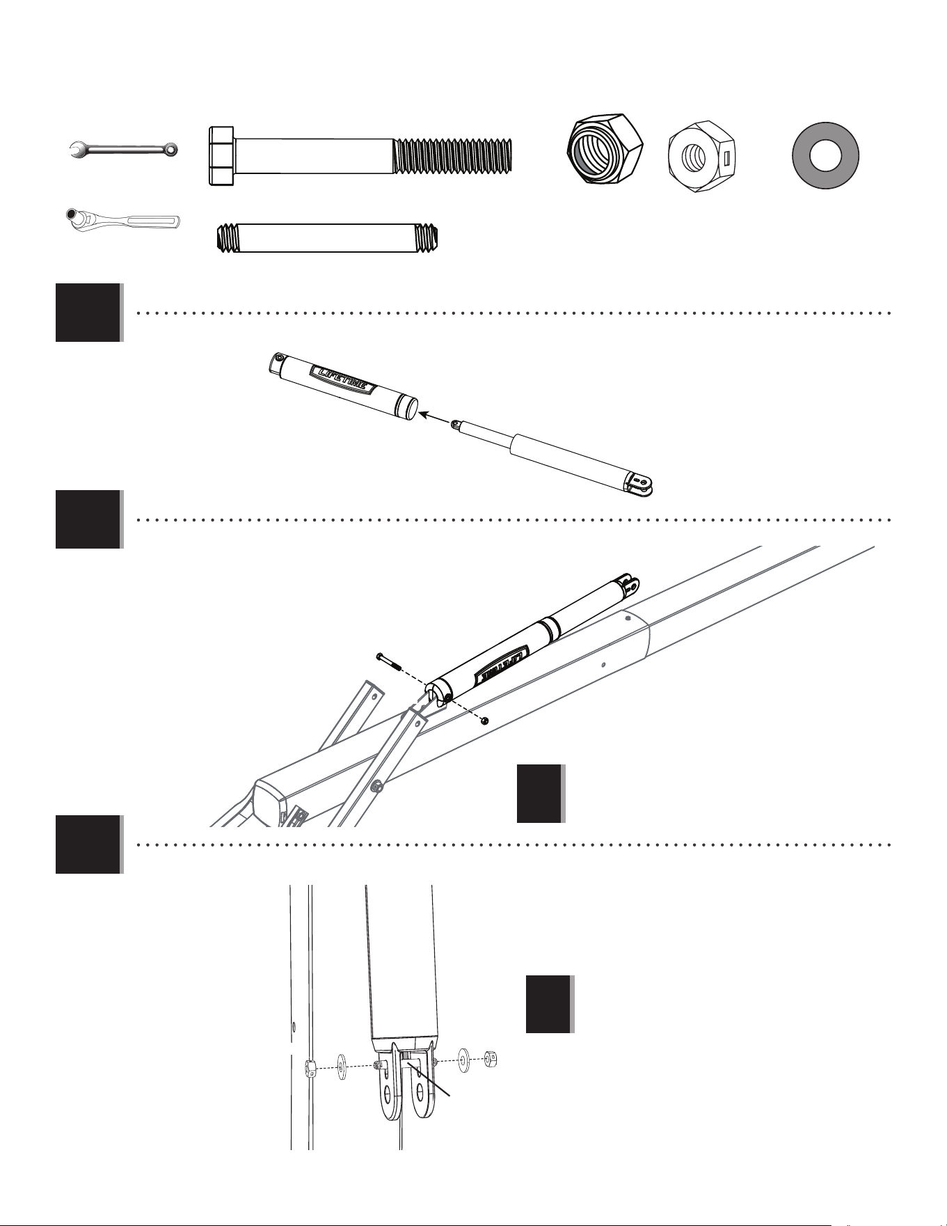
5.1
5.2
ACX (x1)
AAO (x1)
• Slide the Gas Spring Cover (AKG) onto the Gas Spring (AKF) as shown.
• Align the holes in the Gas Spring Cover (AKG) and the Gas Spring (AKF) with the holes in the Pole Bracket (ALL), and attach
the Gas Spring assembly to the Pole Bracket with the hardware shown.
(2)
• Tighten the Nylock Nut (AAO) until it is
fl ush with the end of the Bolt.
!
AKG
AKF
AKG
AKF
ACX
AAO
ALL
5.3
• Connect the Gas Shock Rod (CKZ) to the Gas Spring in the location pictured using the hardware shown.
CKZ (x1)
AAB (x2)
AEB (x2)
CKZ
AAB
AEB
AAB
AEB
(2)
AKF
• DO NOT overtighten the hardware. The Gas Shock
Rod should move freely.
!
7/16" (≈11 mm)
1/2" (≈13 mm)
27
SECTION 5 (CONTINUED)
TOOLS AND HARDWARE REQUIRED
5.4
CKW (x1)
CKW
BFI (x1)
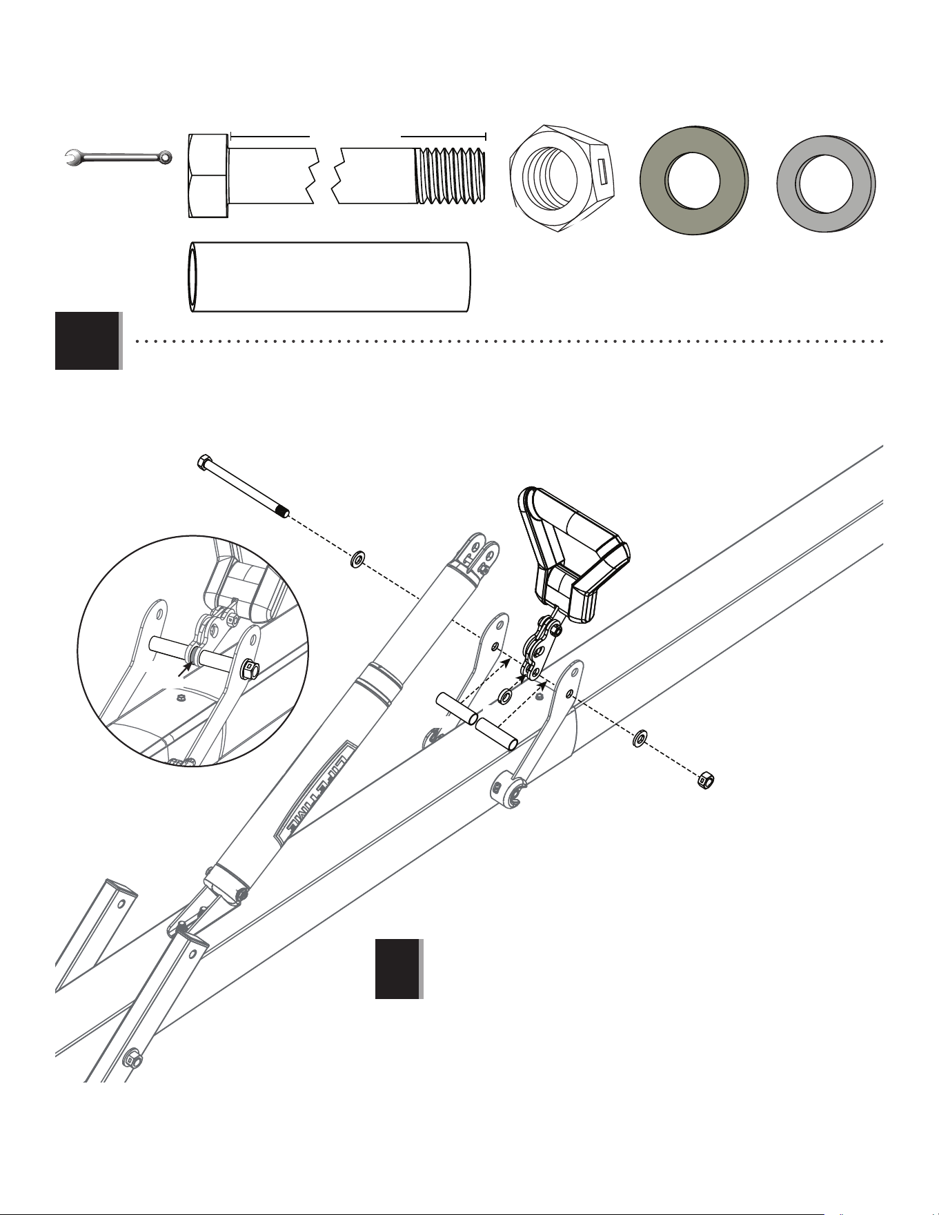
BFI
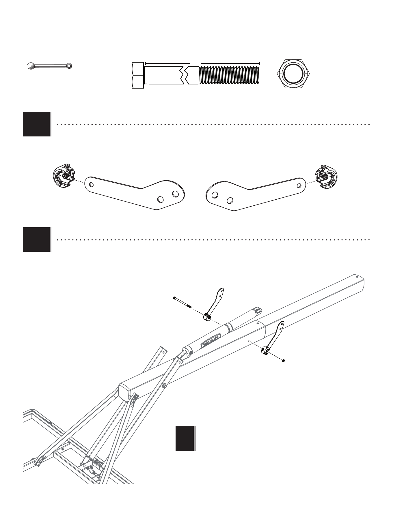
• Slide the Link Cap (CKG) onto the Pump Adjust Link (CKM). Repeat this for the second Link, with the Link Cap fl ipped over.
(2)
• Tighten the Centerlock Nut (BFI)
until it is fl ush with the end of the
Bolt.
!
CKG
CKM
CKM
CKM
6”
5.5
• Secure the Pump Adjust Links (CKM) to the Pole Assembly using the hardware as shown.
CKG
CKM
9/16" (≈15 mm)
28
SECTION 5 (CONTINUED)
TOOLS AND HARDWARE REQUIRED
5.6
5.7
• Position the Handle Frame (CKJ) inside of the Top Handle (CKH) and Bottom Handle (CKI) as shown, and secure with the
hardware shown.
• Secure the Pump Adjust Actuators (CMR) to the Handle with the hardware shown.
• Tighten the Nut (ABB) until
it is fl ush with the end of
the Bolt (FHM).
!
CKJ
FHM
CKV
CMR
CMR
CKV
CKH
CKI
ADT
ADT
ADT
ADT
ADT
ADT
ADT
ADT (x7)
ABB (x1)
CKV (x2)
(2)
(1)
9/16”
(≈15 mm)
ABB
FHM (x1)
29
SECTION 5 (CONTINUED)
TOOLS AND HARDWARE REQUIRED
6 1/2” (16.5 cm)
5.8
• Line up the hardware and spacers shown with the hole nearest to the pole on the Pump Adjust Links (CKM) and
the Pump Adjust Actuators (CMR). Secure with the Centerlock Nut (AAX).
AAW (x1)
AAW
AAX
ABN
ABN
ANZ
CKX
CKX
AAX (x1)
ABN (x2)
ANZ (x1)
CKX (x2)
(2)
• Tighten the Centerlock Nut (AAX) until it is fl ush with
the end of the Bolt.
!
ANZ
CKX
CKX
3/4" (≈19 mm)
30
SECTION 5 (CONTINUED)
TOOLS AND HARDWARE REQUIRED
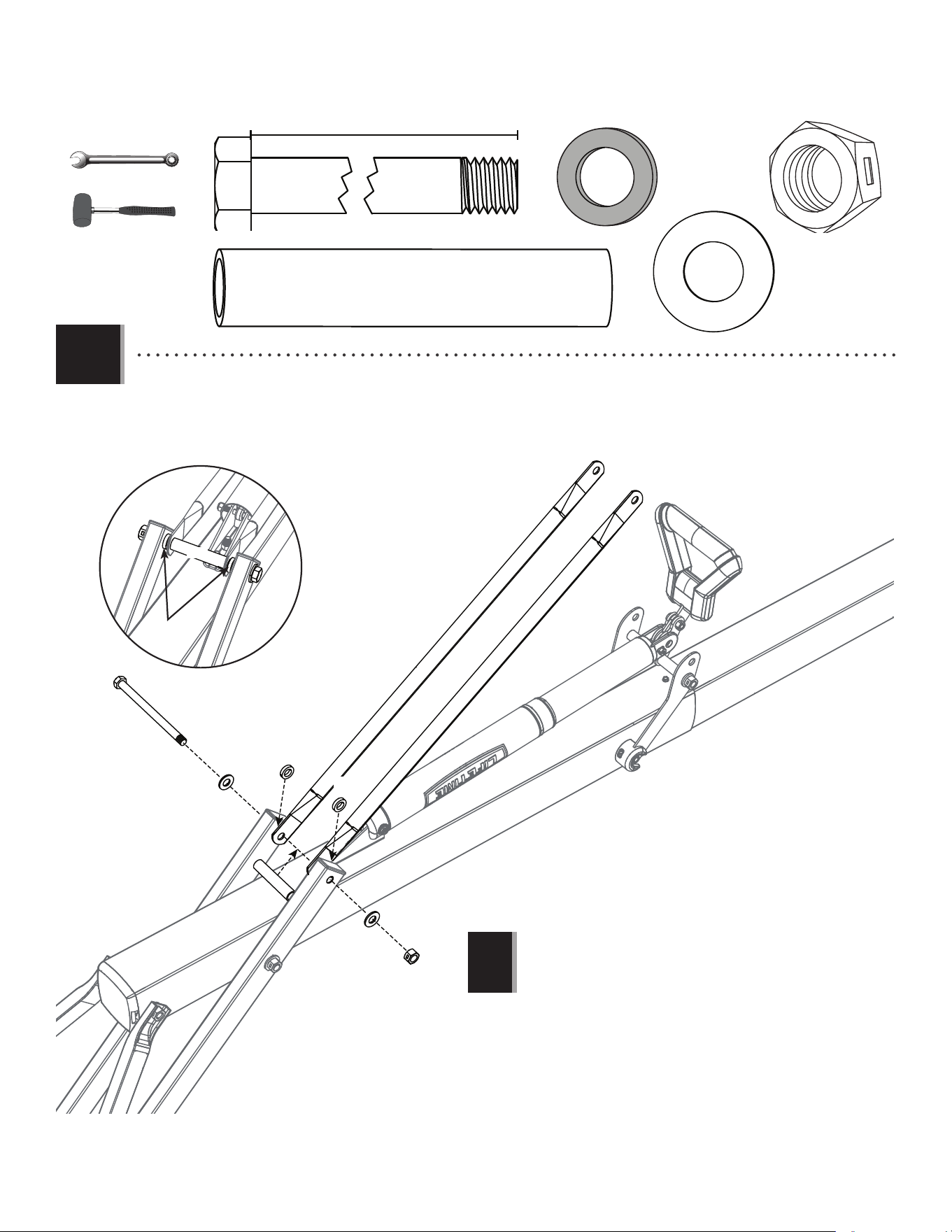
5.9
(2)
• Connect the Rear Lifter Arms (ALS) to the inside of the Long Extension Arms (AKB) with the hardware shown. Place a
Spacer (CKT) between the Rear Lifter Arms as shown, with a Spacer (ANZ) between the Rear Lifter Arms and the
Long Extension Arms on each side. Tighten the hardware in this step and in steps 4.3 securely now.
AAX (x1)
AOR (x2)
ANZ (x2)
AAD (x1)
CKT (x1)
CKT
ANZ
ANZ
ALS
ALS
ANZ
AAX
AOR
AOR
AAD
• Tighten the Centerlock Nut (AAX)
until it is fl ush with the end of
the Bolt.
!
CKT
(1)
3/4"
(≈19 mm)
31
SECTION 5 (CONTINUED)
TOOLS AND HARDWARE REQUIRED
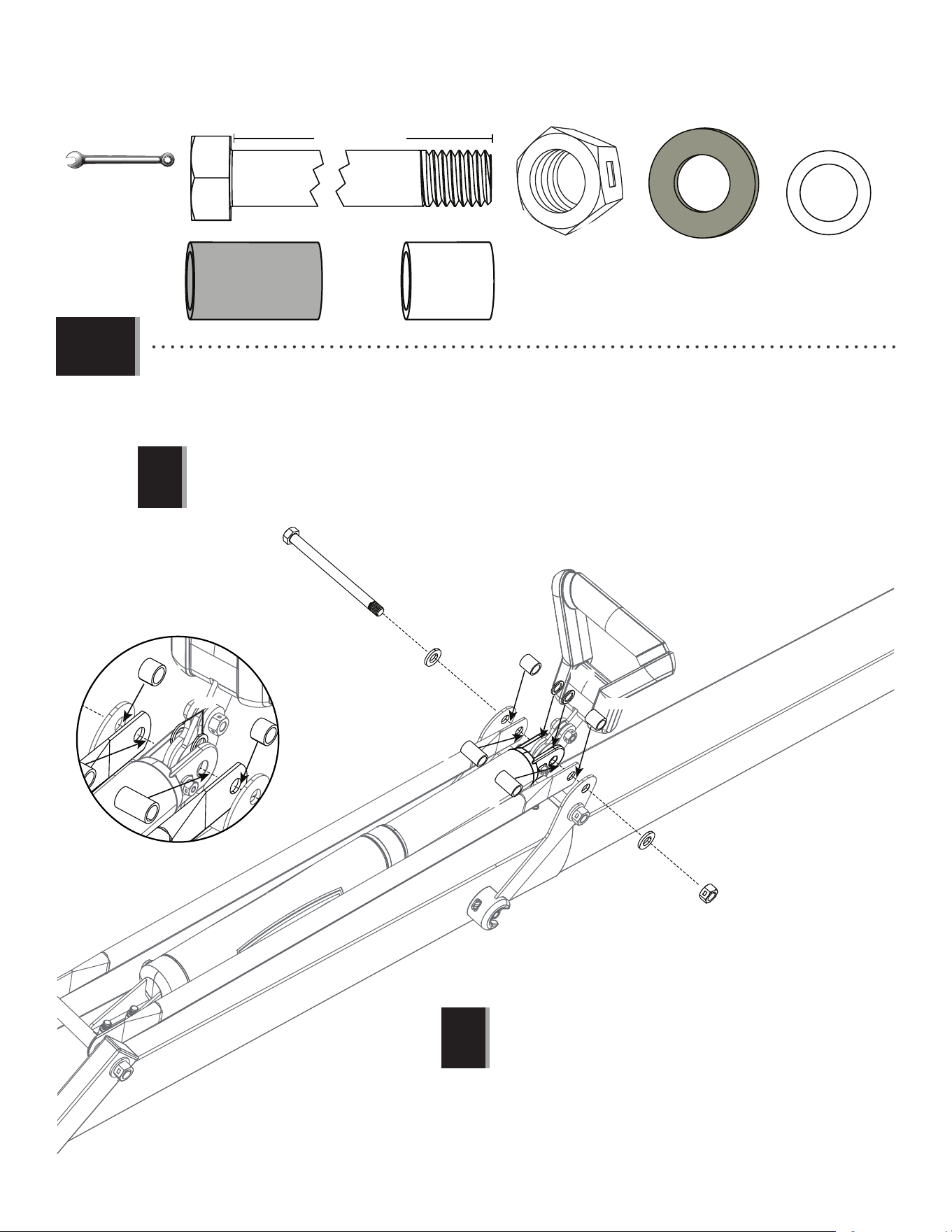
• Finish connecting the Handle Assembly to the Gas Spring (AKF) with the hardware shown. Make sure to place a
Nylon Washer (ANK) between the Gas Spring and the Handle Assembly on each side of the Handle Assembly as
shown.
AAW
ABN
CKU
CKU
CKY
CKY
ANK
ABN
AAX
• Tighten the Centerlock Nut (AAX)
until it is fl ush with the end of
the Bolt.
• The Rear Lifter Arms must be on the inside of
the Long Extension Arms.
!
!
6 1/2” (16.5 cm)
AAW (x1)
AAX (x1)
ABN (x2)
ANK (x2)
CKY (x2)
CKU (x2)
(2)
ANK
5.10
3/4" (≈19 mm)
32
SECTION 5 (CONTINUED)
TOOLS AND HARDWARE REQUIRED
5.11
• Apply grease from the Grease Packet (AKH) on to the Gas Shock Rod (CKZ).
AKH (x1)
AKH
CKZ
33
Plastic Parts
TOOLS REQUIRED
PARTS REQUIRED
HARDWARE REQUIRED
FINAL ASSEMBLY
6
AKZ (x1)
(x1)
(x1)
(x3)
(x1)
(x1)
(not included)
CMV (x1)
BCO
Hardware Bag
• Hardware used in this Section is taken
from the remaining Section 2 hardware.
!
AKP (x1)
1109 02 5
10’
9’6”
9’
8’6”
7’6”
8’
(x1)
34
SECTION 6 (CONTINUED)
TOOLS AND HARDWARE REQUIRED
6.1
6.2
AKZ
ALX
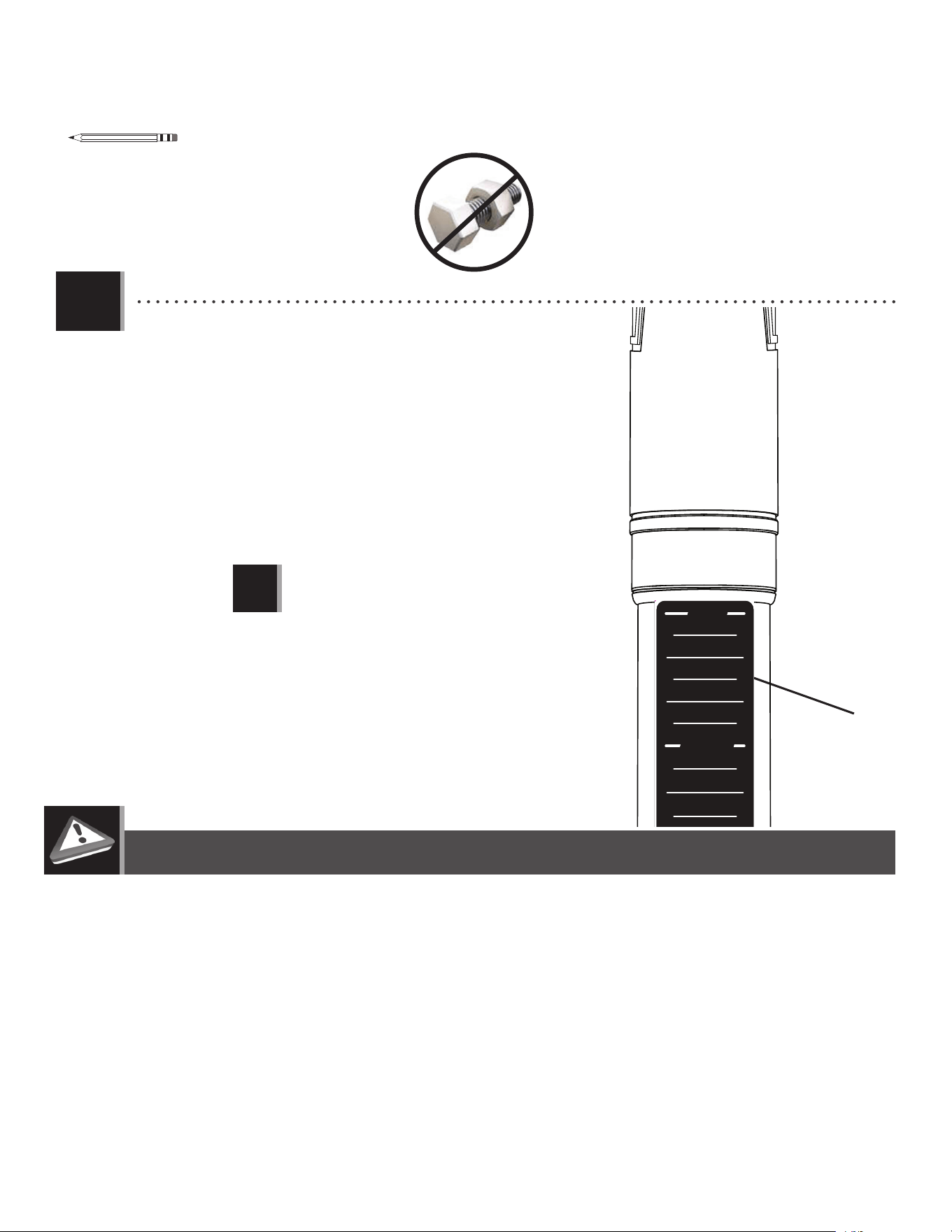
• BEFORE CONTINUING: It is critical that the instructions in the following steps are followed exactly.
Failure to properly orient and align the pole sections will render the pole unusable. If the pole
sections are assembled incorrectly, you will have to purchase new pole sections from our
Customer Service Department. If you have questions regarding the pole assembly, please call
our Customer Service Department for assistance.
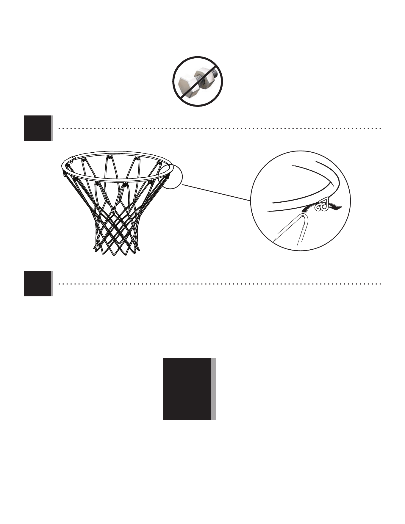
• Attach the Net (AKZ) to the Rim (ALX).
!
35
SECTION 6 (CONTINUED)
TOOLS AND HARDWARE REQUIRED
6.3
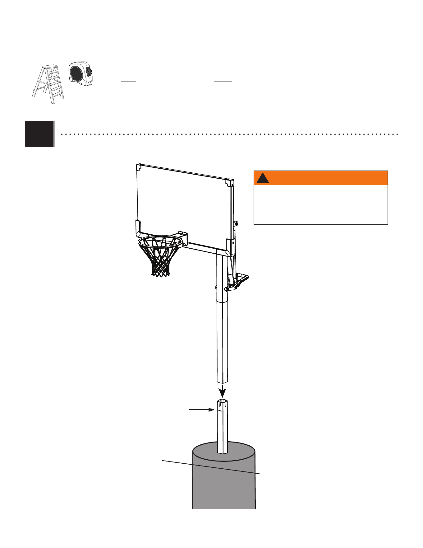
• Make a mark 5 inches from the top of the Bottom Pole (ALE). With the Backboard facing the playing surface,
carefully slide the Top/Middle Pole assembly over the Bottom Pole. Adjust the system to the 7.5-foot setting.
ALH
ALE
ALF
5” mark
Playing
Surface
(x3)
AT LEAST THREE ADULTS ARE REQUIRED. DO NOT ATTEMPT ASSEMBLY WITH FEWER
THAN THREE ADULTS AND THREE LADDERS.
(x1)
WARNING
Use extreme caution when standing on ladders to
perform assembly steps. Follow all warnings and
cautions on the ladder. Failure to follow all of these
instructions and warnings could lead to serious
personal injury or property damage.
!
36
SECTION 6 (CONTINUED)
TOOLS AND HARDWARE REQUIRED
6.5
6.4
Wood Block
• While two people continue to hold the assembly in place, set a block of Scrap Wood on top of the Lower
Extension Arms and strike it 5-6 times with a hammer or mallet. You must have wood on top of the Arms before hitting
them with a hammer to prevent scratching the powder coating. The bottom edge of the Middle Pole must reach within
1/2 inch of the 5-inch mark on the Bottom Pole.
• After the Poles have been seated, measure up 1" from the bottom center of the Middle Pole (ALF) and insert one
Self-Drilling Screw (CMV) into the Pole as shown.
• If your Pole sections do not reach within 1/2" of the 5"
mark after seating, DO NOT COMPLETE ASSEMBLY. Call
our Customer Service number for assistance.
!
(x1)
CMV
ALH
CMV (x1)
1" up from bottom of
Top Pole
(x1)
(x1)
WARNING
The Poles must be seated together! Poles must
be struck on a hard surface five to six times!
Failure to seat the Poles correctly could allow the
Poles to separate during use, which could lead
to serious personal injuries or property damage.
37
The life of your basketball system depends on many variables. The climate, exposure to corrosives such as salt, pesticides, or herbicides,
and excessive use or misuse can all contribute to Pole failure, which may cause property damage or personal injury.
Check your basketball system frequently for loose hardware, excessive wear, and signs of corrosion. For safety reasons, and to
prolong the life of your basketball system, you must take the following preventive measures.
a. Check all Nuts and Bolts. If any are loose, tighten them.
b. Check all parts for excessive wear and tear. If necessary, replace any parts that have been worn or damaged through usage.
Contact our Customer Service Department for replacement parts.
c. Inspect the Warning Sticker on the Pole. If it is ripped, faded, or illegible, call our Customer Service Department to request
a replacement Sticker.
d. Check all Pole sections for visible rust or chipped or cracked paint. If either are present, do the following:
1. Use an emery cloth to completely remove any rust or chipped paint.
2. Clean the area with a damp cloth and allow it to dry.
3. Apply two coats of a rust preventative, high gloss enamel paint to the area. Allow the paint to dry between coats.
IF RUST HAS PENETRATED THROUGH THE POLE ANYWHERE, REPLACE IT IMMEDIATELY!
SECTION 6 (CONTINUED)
TOOLS AND HARDWARE REQUIRED
6.6
(x1)
• Actual Height Sticker (AKP) and Gas
Spring Cover (AKG) may vary from
those shown here.
!
• Raise the Backboard until the top of the Rim measures 10 feet from
the playing surface. Apply the Height Adjustment Sticker (AKP) onto the
Gas Spring (GFL), lining up the edge of the Gas Spring Cover with the 10-
foot mark on the sticker. Press the sticker into place while carefully
removing the rest of the backing.
AKP
1202457
10'
9.5'
9'
8.5'
7.5'
8'
AKF
AKG
MAINTENANCE
38
WARNING STICKER
FAUTE DE NE PAS SUIVRE CES AVERTISSEMENTS, VOUS RISQUEZ DE CAUSER
DES BLESSURES GRAVES ET/OU DES DOMMAGES À L’ÉQUIPEMENT.
Le propriétaire doit s’assurer que tous les joueurs con-
naissent et appliquent les règles suivantes afin d’utiliser
l’équipement en toute sécurité.
SI NO SE OBEDECEN ESTAS ADVERTENCIAS PUEDEN PRODUCIRSE
GRAVES LESIONES Y/O DAÑOS A LA PROPIEDAD.
El propietario del sistema debe asegurarse de que todos
los jugadores conozcan y respeten estas reglas para que el
sistema se use en forma segura.
WARNING
FAILURE TO FOLLOW THESE WARNINGS MAY RESULT IN SERIOUS INJURY
AND/OR PROPERTY DAMAGE.
Owners must ensure that all players know and follow these
rules for safe operation of the system.
• Only hang from the Rim briefly to regain balance or avoid
injuring others. Release the Rim as soon as safely possible.
• During play, especially when performing dunk type activities,
keep player’s face away from the Backboard, Rim, and Net.
Serious injury could occur if teeth/face come in contact with
the Backboard, Rim, or Net. Player should wear a mouth
guard during play.
• Do not slide, climb, or play on Base or Pole.
• When adjusting height or moving system, keep hands and
fingers away from moving parts.
• Do not allow children to move or adjust system.
• Do not wear jewelry (rings, watches, necklaces, etc.) during
play. Objects may entangle in Net.
• Keep water and organic material away from Pole Base. Grass,
litter, etc. could cause corrosion and/or deterioration.
• Never play on damaged equipment.
• Once a month check Pole and all metal parts for signs of
corrosion (rust, pitting, chipping). Completely remove rust and
repaint with exterior enamel. If rust has penetrated any steel
part, replace that part immediately.
• Check system before each use for proper ballast, loose
hardware, excessive wear, instability, and signs of corrosion
and repair before use.
• Do not use the system to lift or hoist anything. The
mechanism is designed to lift only the weight of the
Backboard and Rim. Do not hang anything from the Handle,
Rim, Backboard, or Lifter Arms as this will damage the
system and void the warranty.
• Ne vous suspendez pas à l’anneau plus que nécessaire pour
retrouver votre équilibre ou éviter de blesser les autres joueurs.
Relâchez l’anneau aussitôt que possible.
• Lors d’un match, particulièrement dans le cas des smashs, le
visage du joueur ne doit pas faire face au panneau, à l’anneau, ni au
filet. Le joueur risque de graves blessures si ses dents ou son visage
entrent en contact avec le panneau, l’anneau, ou le filet. Les joueurs
doivent toujours porter un protège-dents lorsqu’ils jouent.
• Ne glissez pas, ne grimpez pas, et ne jouez pas sur la base ou le
poteau.
• Lorsque vous ajustez la hauteur ou lorsque vous déplacez
l’équipement, gardez vos mains et doigts loin des pièces mobiles.
• Ne permettez pas aux enfants de déplacer ou d’ajuster
l’équipement.
• Ne portez pas de bijoux (bagues, montres, colliers, etc.) lorsque
vous jouez. Ces objets pourraient s’accrocher au filet.
•Gardez de l’eau et de la matiére organique loin de la base. Le
gazon, les déchets, etc. pourraient provoquer la corrosion et/ou la
détérioration.
• Une fois par mois, vérifiez que le Poteau et toutes les pièces en
métal ne montrent pas de signes de corrosion (rouille, piqûres,
écaillage). Enlevez toute la rouille et repeignez complètement avec
une peinture pour extérieur. Si la rouille a pénétré une des pièces en
acier, vous devrez remplacer immédiatement la pièce en question.
• A chaque fois que vous allez utiliser l’équipement, vérifiez d’abord
l’équilibre, la possibilité de pièces desserrées ou usées, la stabilité
de l’équipement et tout signe de corrosion ou réparation nécessaire
avant utilisation.
• Ne jouez jamais avec un équipement endommagé.
• N’utilisez pas l’équipement pour lever ou soulever quoique ce soit.
Son mécanisme a été conçu uniquement pour soutenir le poids du
panneau et de l’anneau. N’accrochez rien au manche, à l’anneau,
au panneau ni aux leviers sous peine d’endommager l’équipement
et d’annuler la garantie.
• Cuélguese del aro sólo en forma breve, para recuperar el equilibrio
o evitar lesionar a otros jugadores. Suéltese del aro lo más pronto
que pueda hacerlo con seguridad.
• Durante el juego, especialmente al embocar violentamente de
alto, la cara de los jugadores debe mantenerse alejada del tablero,
el aro y la red. Pueden producirse lesiones graves si los dientes o la
cara entran en contacto con el tablero, el aro o la red. Los jugadores
deben usar un protector bucal durante el juego.
• No se deslice, no trepe ni juegue sobre la base o el poste.
•Mantenga las manos y los dedos alejados de las piezas movibles
cuando regule la altura o desplace el sistema.
• No deje que los niños regulen ni desplacen el sistema.
• No use joyas (anillos, relojes, collares o gargantillas, etc.) durante el
juego. Estos objetos pueden engancharse en la red.
• Guarde aqua y materia orgánica. Césped, basura,etc., prodrian
causar corrosión et/o deterioros.
• Controle el poste y todas las piezas metálicas una vez al mes
en busca de signos visibles de corrosión (oxidación, picaduras,
escamado). Elimine todo rastro de óxido y vuelva a pintar con
esmalte para exteriores. Si el óxido ha penetrado cualquier pieza de
acero, reemplace esa pieza de inmediato.
• Inspeccione el sistema antes de cada uso para verificar que esté
adecuadamente contrapesado, que los elementos de fijación no
estén flojos, que no haya desgaste excesivo, inestabilidad ni signos
de corrosión. Si encuentra irregularidades, repárelas antes de usar
el sistema.
• Nunca juegue con un equipo dañado.
•No use el sistema para levantar ningún objeto. El mecanismo está
diseñado para elevar solamente el peso del tablero con el aro. No
cuelgue nada de la agarradera, el aro, el tablero ni los brazos de
elevación, ya que esto puede dañar el sistema y anular la garantía.
www.lifetime.com
# 1176611
ADVERTENCIAAVERTISSEMENT
Lifetime Products, Inc., Clearfield, UT 84016
1-800-225-3865
7/12/2016

39
NOTES / REMARQUES / NOTAS

40
NOTES / REMARQUES / NOTAS

41
NOTES / REMARQUES / NOTAS

42
LIFETIME’S PROMISE TO YOU:
We invite you to read our privacy policy at www.lifetime.com
REGISTER today!
At Lifetime
®
, we are committed to providing innovative and quality products. While registering, you will have the opportunity to give us your feedback. Your input is
valuable to us.
• You can also opt in to receive new product notifi cations or promotions.
• In the unlikely event of a product recall or safety modifi cation, your registration provides the information we need to notify you directly.
• Registration is fast, easy, and completely voluntary.
Maintaining your privacy is our long-standing policy at Lifetime
®
. And you can rest assured that Lifetime
®
will not sell or provide your
personal data to other third parties, or allow them to use your personal data for their own purposes.
REGISTER YOUR PRODUCT ONLINE AT WWW.LIFETIME.COM
LA PROMESA DE LIFETIME
®
PARA USTED:
Lo invitamos a leer nuestra política de privacidad en www.lifetime.com (sólo en inglés)
¡REGISTRARSE hoy mismo!
En Lifetime
®
, estamos comprometidos a ofrecer productos innovadores y de calidad. Al registrarse, usted tendrá la oportunidad de darnos su retroalimentación.
Su información es valiosa para nosotros.
• También puede optar por recibir nuestras notifi caciones o promociones.
• En el caso improbable de que el producto deba ser retirado del mercado o que sufra alguna modifi cación, su registro provee la
información que necesitamos para notifi carle directamente.
• El registro es rápido, fácil y completamente voluntario.
Mantener privacidad es nuestra política permanente en Lifetime
®
. Y puede estar seguro que Lifetime
®
no venderá ni dará datos personales a
terceros, ni les permitirá usar datos personales para sus propios fi nes.
REGISTRAR EL PRODUCTO EN LÍNEA EN WWW.LIFETIME.COM
LA PROMESSE DE LIFETIME :
Nous vous invitons à lire notre politique de confi dentialité à www.lifetime.com (en anglais seulement)
ENREGISTRER CE PRODUIT aujourd’hui!
Chez Lifetime
®
, nous nous engageons à fournir des produits innovateurs de qualité. Lors de votre inscription, vous aurez l’occasion de nous faire parvenir vos
commentaires. Votre opinion est importante pour nous.
• On peut également choisir de recevoir des avis ou des promotions dans le cadre de nouveaux produits.
• Dans l’éventualité improbable d’un rappel ou d’un avis de sécurité, l’inscription fournit les renseignements nécessaires nous
permettant de communiquer avec vous.
• L’inscription est rapide, facile et complètement volontaire.
Conserver votre confi dentialité est notre politique de longue date chez Lifetime
®
. Vous pouvez donc être rassuré par le fait que Lifetime
®
ne
vendra pas ou ne fournira pas vos données personnelles à des tiers, et ne leur permettra pas d’utiliser vos données personnelles à leurs
propres fi ns.
ENREGISTRER CE PRODUIT EN LIGNE À WWW.LIFETIME.COM

43
THE MANUFACTURER RESERVES THE RIGHT TO MAKE SUBSTITUTIONS TO WARRANTY CLAIMS IF PARTS ARE UNAVAILABLE OR OBSOLETE.
1. Lifetime basketball systems are warranted to the original purchaser to be free from defects in material or workmanship
for a period of fi ve years from the date of original retail purchase. The word “defects” is defi ned as imperfections that
impair the use of the product. Defects resulting from misuse, abuse or negligence will void this warranty. This warranty
does not cover defects due to improper installation, alteration or accident. This warranty does not cover damage caused
by vandalism, rusting, “acts of nature” or any other event beyond the control of the manufacturer.
2. This warranty does not cover breakage of the tempered glass playing surface.
3. This warranty is nontransferable and is expressly limited to the repair or replacement of defective product. If the product
is defective within the terms of this warranty, Lifetime Products, Inc. will repair or replace defective parts at no cost to
the purchaser. Shipping charges to and from the factory or distribution center are not covered and are the responsibility
of the purchaser. Labor charges and related expenses for removal, installation or replacement of the basketball system
or its components are not covered under this warranty.
4. This warranty does not cover scratching or scuffi ng of the product that may result from normal usage. In addition,
defects resulting from intentional damage, negligence, unreasonable use or hanging from the rim will void this warranty.
5. Liability for incidental or consequential damages is excluded to the extent permitted by law. While every attempt is made
to embody the highest degree of safety in all equipment, freedom from injury cannot be guaranteed. The user assumes
all risk of injury resulting from the use of this product. All merchandise is sold on this condition, and no representative
of the company may waive or change this policy.
6. This product is not intended for institutional or commercial use; Lifetime Products, Inc. does not assume any liability for
such use. Institutional or commercial use will void the warranty.
7. Our goods come with guarantees that cannot be excluded under the Australian Consumer Law. You are entitled to a
replacement or refund for a major failure and for compensation for any other reasonably foreseeable loss or damage.
You are also entitled to have the goods repaired or replaced if the goods fail to be of acceptable quality and the failure
does not amount to a major failure.
8. This warranty is expressly in lieu of all other warranties, expressed or implied, including warranties of merchantability
or fi tness for use to extent permitted by Federal and state law. Neither Lifetime Products, Inc., nor any representative
assumes any other liability in connection with this product. This warranty gives you specifi c legal rights, and you may
also have other rights which vary from state to state.
www.lifetime.com
PLEASE INCLUDE YOUR DATED SALES RECEIPT AND PHOTOGRAPHS OF DAMAGED PARTS.
REPORT PRODUCT DEFECTS IN WRITING TO:
Lifetime Products, Inc., PO Box 160010 Clearfi eld, UT 84016-0010
or call 1-800-225-3865 M-F 7 a.m. to 5 p.m. MST.
REGISTER YOUR PRODUCT FOR QUICKER CUSTOMER SERVICE.
Visit www.lifetime.com or call 1-800-225-3865 to register your product today.
FOR INTERNATIONAL WARRANTY CLAIMS:
All warranty claims must be accompanied by a sales receipt. Report all warranty claims in writing to your regional sales
support representative. Please include your dated sales receipt and photographs of damaged parts.
To Identify the representative for your region, please visit: www.lifetime.com/international
5-YEAR LIMITED FACTORY WARRANTY
W
A
R
R
A
N
T
Y
W
A
R
R
A
N
T
Y
WARRANTY
44
www.lifetime.com
Or call: 1-800-424-3865
7:00 am–5:00 pm (M–F) MST and 9:00 am–1:00 pm Saturday MST
To purchase accessories or other Lifetime
®
products, visit us at:
www.lifetime.com
ENHANCE YOUR LIFETIME
®
PURCHASE BY ADDING ACCESSORIES OR OTHER GREAT PRODUCTS
© 2021
Lifetime Products, Inc., Clearfi eld, UT