
Technical Support and E-Warranty Certificate
www.vevor.com/support
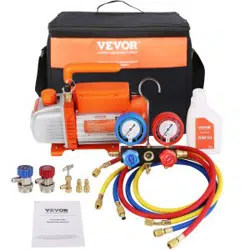
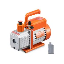
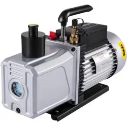
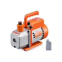
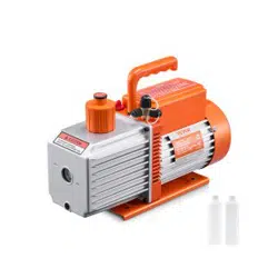
VACUUM PUMP
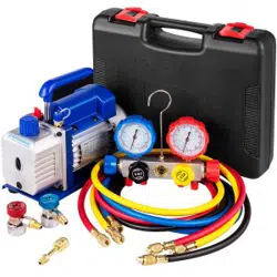
REFRIGERANT METER GROUP
MODEL: RS-0.5,RS-1, RS-1.5, RS-2
We continue to be committed to provide you tools with competitive price.
"Save Half", "Half Price" or any other similar expressions used by us only represents an
estimate of savings you might benefit from buying certain tools with us compared to the
major top brands and does not necessarily mean to cover all categories of tools offered by
us. You are kindly reminded to verify carefully when you are placing an order with us if you
are actually saving half in comparison with the top major brands.

- 1 -
MODEL: RS-0.5,RS-1, RS-1.5, RS-2
Have product questions? Need technical support? Please feel free to
contact us:
Technical Support and E-Warranty Certificate
www.vevor.com/support
NEED HELP? CONTACT US!
This is the original instruction, please read all manual instructions
carefully before operating. VEVOR reserves a clear interpretation of our
user manual. The appearance of the product shall be subject to the
product you received. Please forgive us that we won't inform you again if
there are any technology or software updates on our product.
VACUUM PUMP
REFRIGERANT METER GROUP
- 2 -
SAFETY INSTRUCTION
Beforeoperatingthisappliance, pleaseread the instructions manual carefully
andsavetheseinstructions.Basicsafetyprecautionsshouldalwaysbefollowed,
including thefollowing:
Warning-Toreduce the risk of injury, the user must read the
instructionsmanual carefully.ed
Thissymbol, placed before a safety comment, indicates a kind of
precaution, warning, or danger. Ignoring this warning may lead to
anaccident.To reduce the risk of injury, fire, or electrocution,
pleasealwaysfollow the recommendation shown below.
WARNING
Household Use Only.
WARNING: Hot Surface-To reduce the risk of burns, do not touch.
CAUTION: To reduce the risk of electric shock, do not expose to rain.Store indoors.
CAUTION: To reduce the risk of electric shock, use indoors only.
WARNING:Risk of injury-Do not direct air steam at the body.
Utilisez seulement des menages.
AVERTISSEMENT:Surface chaude-Pour reduire le risque de brolures,ne touchez pas.
ATTENTION: Pour reduire le risque de choc electrique, ne pas exposer a la pluie.
Stockez indoorsduce100
ATTENTION: Pour reduire le risque de choc electrique, utilisez uniquement a linter-
ieur.AVERTISSEMENT:RIsquedeblessure-Nepas courant dair directe sur le corps.
- 3 -
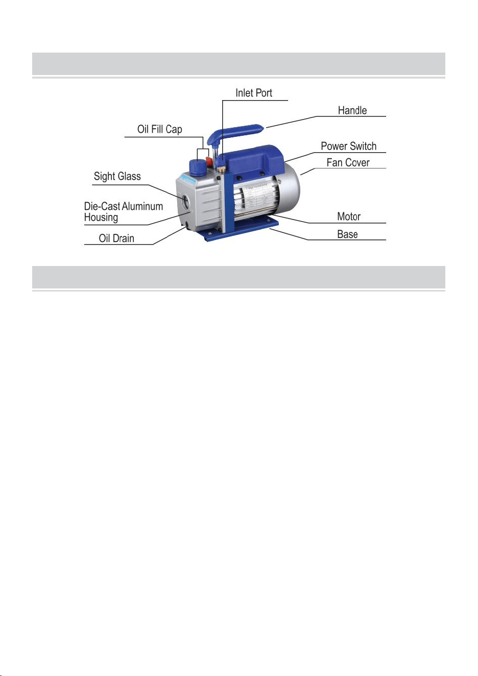
PUMP COMPONENTS
OPERATING MANUAL
1.Before using your vacuum pump
In all cases, motors are designed for operating voltages plus or minus 1 0 % of the
normal rating. Single voltage motors are supplied fully connected and ready to
operate.
( 1 ) Check to be sure the voltage and frequency at the outlet match the specifica-
tions on the pump motor decal. Check the ON- OFF switch to be sure it is in the OFF
position before you plug the pump into an outlet. Remove and discard the exhaust
cap from the end of the pump’ s handle.
( 2 ) The pump is shipped without oil in the reservoir. Before starting the pump, fill
it with oil. Remove the Exhaust Fitting cap and add oil until the oil just shows in the
bottom of the sight glass. The approximate oil capacity of the pump is
1 8 0 ~ 8 0 0 ml( reference the technical data) .
( 3 ) Replace the Exhaust Fitting cap and remove the cap from one of the inlet
ports. Turn the motor switch to ON. When the pump runs smoothly, replace the cap
on the inlet port. This may take from two to 3 0 seconds, depending on the ambient
temperature. After the pump runs for approximately one minute, check the sight
glass for the proper oil level. The level should be even with the sight glass oil level
line. Add oil if necessary.
Note:When the pump is running, the oil level should be even with the line on
the sight glass. Underfilling will result in poor vacuum performance. Overfilling can
result in oil blowing from the exhaust.

- 4 -
2.To shut down your pump after use
To help prolong pump life and promote easy starting. Follow these procedures
for shut down.
( 1 ) Close the manifold valve between the pump and the system.
( 2 ) Remove the hose from the pump inlet.
( 3 ) Cap the inlet port to prevent any contamination or loose particles from entering
the port.
TO MAINTAIN YOUR HIGH VACUUM PUMP
1.Vacuum pump oil:
The condition and type of oil used in any high vacuum pump are extremely
important in determining the ultimate attainable vacuum. We recommend the use of
High Vacuum Pump Oil.Thisoil has been specifically blended to maintain maximum
viscosity at normal running temperatures and to improve cold weather starts.
2.Oil Change Procedure
(1)Be sure the pump is warmed up.
(2)Remove the OIL DRAIN cap. Drain contaminated oil into a suitable container
and dispose of it properly. Oil can be forced from the pump by opening the inlet
and partially blocking the exhaust with a cloth while the pump is running.
Do not operate the pump for more than 20 seconds using this method.
(3)When the flow of oil has stopped, tilt the pump forward to drain residual oil.
(4)Replace the OIL DRAIN cap.Remove the exhaust fitting and fill the reservoir
with new vacuum pump oil until the oil just shows at the bottom of the sight
glass. The approximate oil capacity of the pump is 180-800ml(reference the technical
data).
(5)Be sure the inlet ports are capped, then turn on the pump. Allow it to run for
one minute,then check the oil level space. If the oil is below the sight glass OIL
LEVEL line, add oil slowly (with the pump running )until the oil reaches the OIL
LEVEL line.Replace the exhaust fitting, making sure the inlet is
(6)
a)Ifthe oil isbadly contaminated with sludge that forms when water is allowed
tocollect intheoil,you may need to remove the oil reservoir cover and wipe
it out.
b)Anothermethod of dealing with heavily contaminated oil is to force the oil from
thepumpreservoir. To do this, allow the pump to run until it is warmed up. While the
pump is still running, remove the oil drain cap. Slightly restrict the exhaust. This will back-
pressure theoil reservoir andforce the oil from it, carrying more contamination.
When the oil ceases to flow, turn off the pump.
Repeat this procedure as required until the contamination is removed.
Replacethe OIL DRAIN cap and refill the reservoir to the proper level with
freshpump oil.

- 5 -
TROUBLESHOOTING GUIDE
Your pump has been for dependable use and has a long life. If something should
go wrong, the following guide will help you get the pump back into service as quickly
as possible.
If the disassembly of the pump is required, please check your warranty.The warranty
may be voided by misuse or customer tampering, which results in the pump being
inoperable.
1.Failure To Start
Check the line voltage. The pump needs to start at±10% line voltage (loaded)
at 320F.At extremes,switching between the standard run windings may occur.
2.Oil leakage
(1)Be sure the oil is not a residual accumulation from spillage, etc.
(2)If leakage exists, the module cover gasket or the shaft seal may need replacing.
If leakage exists in the area of the oil drain plug, you may need to reseal the plug
using a commercial pipe thread sealer.
3.Failure To Pull A Good Vacuum
(1)Be sure the vacuum gauge and all connections are in good condition and
leak- free.You can confirm leakage by monitoring the vacuum with a thermistor
gauge while applying vacuum pump oil at connections or suspected leak points.
The vacuum will improve briefly while the oil is sealing the leak.
(2)Be sure the pump oil is clean. A badly contaminated pump may require
several oil flushes.
(3)Be sure the oil is at the proper level.For maximum pump operation, the oil
must be even with the OIL LEVEL line on the sight glass when the pump is
running. Do not overfill---- operating temperatures will cause the oil to expand, so
it will appear at a higher level than when the pump is not running. To check the
oil level, start the pump with the inlet capped. Check the oil level in the sight
glass. Add oil if necessary.

- 6 -
COMMONTROUBLESHOOTING
FailureDescription
FaultCause
Solution
LowVacuum
1.Theair inletcap on the spare port
side of the air inlet port is loose.
Tighten the air inlet cap
2. The rubberring inside the air
inletcap on the spare port side of
the air inlet port is damaged
Replacethe rubber ring
3. Insufficient oil
Refuel to the centerline of the oil
gauge
4. The pump oilisemulsified
andunclean
Replacewithnew oil
5. Theoil inlet hole of the pump
isblocked orthe oil supply is
insufficient
Clean the oil inlet hole and filter
mesh
6. Leakage of pipe container
connected to the pump
Checktheconnected pipe
container to prevent leakage
7. Improperpump selection
Check the size of the pumped
container, recalculate and select
the appropriate pump model
8. The pump has been used too
long, and the clearance is
increased due to the wear of parts
Check, repair, or replace the
pump witha new one
OilLeakage
1. The oil seal isdamaged
Replacetheoil seal
2.The oil tank connection is
looseordamaged
Tighten thescrews and replace
the O-ring
Oil Injection
1.Toomuchoil
Drain the oil to the oil level line
2.Theinlet pressure is too high
for a long time
Select the appropriate pump to
increase the pumping speed
Hard Starting
1. The oil temperature is too low
Theair inlet is ventilated,
repeatedly starts the motor or
heatsthe pump oil
2. The motor or power supply is
faulty
Check and repair
3.Foreign objects fall into the
pump
Check and eliminate
4. Thepower supply voltage is
too low
Check the power supply voltage
Note:Ifthe above solutions donotsolve your problem,please contactthenearest dealer, or
sendyourpumpto a professionalrepair center,and we will do ourbestto serveyou.

- 7 -
Refrigerant meter group
USEINSTRUCTIONS
Operation Instructions
Before connection,it should check if the pressure gauges indicate zero.If they do
not,adjust the setting screw on the pressure gauge to set the pointer to zero.
System Connection
First of all,close both high pressure valve and low pressure valve.
Connect and securethe low pressure port - blue tube - (Iowpressure quick connector)
- system low pressure side.
Connlect and secure the highpressureport - red tube - (highpressure quick connector)
- system high pressure side.)
Connect and secure the refill port - yellow tube - (vacuum pump.)
Vacuum System or Recovery
(Caution:For a safe systemand energy saving,it must select proper vacuum pump or
reCoveryunit according to the system pressure)
After the completion of above me ntioned connection, start thevacuum pump or
recovery unit first.
Open both high pressure valve and low pressure valve together,then (open both high
pressure and low pressure quick connectors),the system starts vacuuming or
recovery.
After a certain time (about 10- 30 minutes), check
if the system is vacuumed. (1f the system
is not vacuumed, it should check if there is any leakage in
the system and re-vacuum it after the leakage problem is remedied.)
Close both high pressure valve and low pressure vale together.
Finally, close the vacuum pump or the recovery unit.
Maintain the pressure for 3- 5 minutes to check if there is any leakage in-system.
RefillRefrigerant
Connect the yellow tube with the refrigerant bottle.Open the refrigerant bottle first
(normal upright position),then open the valve inside of the gauge set to purge air from
the yellow tube. Reverse therefrigerant bottle and place it well.Inject the refrigerant
into the high pressure valve up to the specified quantity (According to the
manufacturer' s refill specification). Close the
high pressure valve and place the refrigerant bottle in its normal upright position.

- 8 -
ConfirmRefillEffect
Start the system operation first.
After a certain time (about 5- 10 minutes), check system if both low pressure and high
pressure are in normal condition. If the system pressure is insufficient, it should
slowly open the low pressure valve (must not open the high pressure valve at the
moment). After a proper quantity of gaseous refrigerant (steel bottle in its normal up
right position ) is supplemented close the low pressure valve and check
the system again.
MaintenanceandSafety
Never overexert your force to open or close the valves, otherwise the sealing element
might be damaged.
Always follow the Operation Instructions or operate it under the guide of the specialist.
Never misuse the high pressure and low pressure.
Never open both high pressure valve and low pressure valve together during the refill
operation.
Never use the working medium not in compliance with the indication on the gauge set.
Never let the sight glass aim at any person to avoid any accident.
The pressure gauges are wear parts and they need periodical calibration. For a good
accuracy,normally it should delivery the gauges to
the authority for calibration every 3- 6 months.
Always use them carefully and protect them from vibration or careless falling.
After use, the valves should be released and keep
the instrument well in storage.

- 9 -
TECHNICAL PARAMETER
SKU
ACKDZKB235CFM9U8YV3
Model
RS-1
Voltage
220-240V 50Hz
Free Air Dispalcement
3.5CFM
Ultimate Vacuum
5PA
Rotating Speed
1440
Power(HP)
1/4
Oil Capacity(ml)
220
Dimension(mm)
240*110*220
Weight(Kg)
7
Accessory
Refrigerant meter group
Scope of application: R22 R134A R410A R404A
Three 48 inchs long hoses
1 pair of car air conditioning quick connect
1 pair of 410A adapter
SKU
3CFM1-4HPZKBZJOC1V2
3CFM1-4HPZKBZJ001V3
Model
RS-1
Voltage
220-240V 50Hz
Free Air Dispalcement
3CFM
Ultimate Vacuum
5PA
Rotating Speed
1440
Power(HP)
1/4
Oil Capacity(ml)
220
Dimension(mm)
240*110*220
Weight(Kg)
6.8
Accessory
Refrigerant meter group
Scope of application: R22 R134A R410A
Three 36 inchs long hoses
1 pair of car air conditioning quick connect
SKU
1.8CFM1-4HPZKBZJ1V2
Model
RS-0.5
Voltage
220-240V 50Hz
Free Air Dispalcement
1.8CFM
Ultimate Vacuum
5PA
Rotating Speed
1440
Power(HP)
1/4
Oil Capacity(ml)
220
Dimension(mm)
240*110*220
Weight(Kg)
6.8
Accessory
Refrigerant meter group
Scope of application: R22 R134A R410A
Three 36 inchs long hoses
1 pair of car air conditioning quick connect

- 10 -
SKU
4CFM1/4HPZKB1F001V2
4CFM1/4HPZKB1F001V3
Model
RS-1.5
Voltage
220-240V 50Hz
Free Air Dispalcement
4CFM
Ultimate Vacuum
5PA
Rotating Speed
1440
Power(HP)
1/3
Oil Capacity(ml)
225
Dimension(mm)
270*110*220
Weight(Kg)
7.6
Accessory
Refrigerant meter group
Scope of application: R134A
Three 36 inchs long hoses
1 pair of car air conditioning quick connect
SKU
4CFM1/4HPZKB1F001V1
Model
RS-1.5
Voltage
120V/60HZ
Free Air Dispalcement
4CFM
Ultimate Vacuum
5PA
Rotating Speed
1720
Power(HP)
1/3
Oil Capacity(ml)
225
Dimension(mm)
270*110*220
Weight(Kg)
7.6
Accessory
Refrigerant meter group
Scope of application: R134A
Three 36 inchs long hoses
1 pair of car air conditioning quick connect
SKU
3CFM1-4HPZKBZUMC1V1
Model
RS-1
Voltage
120V/60HZ
Free Air Dispalcement
3CFM
Ultimate Vacuum
5PA
Rotating Speed
1720
Power(HP)
1/4
Oil Capacity(ml)
220
Dimension(mm)
240*110*220
Weight(Kg)
6.8
Accessory
Refrigerant meter group
Scope of application: R22 R134A R410A
Three 36 inchs long hoses
1 pair of car air conditioning quick connect

- 11 -
SKU
4CFM1/3HPZKB4F001V2
Model
RS-1.5
Voltage
220-240V 50Hz
Free Air Dispalcement
4CFM
Ultimate Vacuum
5PA
Rotating Speed
1440
Power(HP)
1/3
Oil Capacity(ml)
225
Dimension(mm)
270*110*220
Weight(Kg)
7.6
Accessory
Refrigerant meter group
Scope of application: R22 R12 R134A R502
Three 36 inchs long hoses
1 pair of car air conditioning quick connect
1 pair of 410A adapter
SKU
MCKDZK44.8CFM7CNVV1
Model
RS-2
Voltage
120V/60HZ
Free Air Dispalcement
4.8CFM
Ultimate Vacuum
5PA
Rotating Speed
1720
Power(HP)
1/3
Oil Capacity(ml)
250
Dimension(mm)
290*120*230
Weight(Kg)
9.3
Accessory
Refrigerant meter group
Scope of application: R410A R22 R134A R404A
Four 60 inchs long hoses
1 pair of car air conditioning quick connect
1 pair of 410A adapter
SKU
MCKDZK43.6CFM6DQYV1
Model
RS-1
Voltage
120V/60HZ
Free Air Dispalcement
3.6CFM
Ultimate Vacuum
5PA
Rotating Speed
1720
Power(HP)
1/4
Oil Capacity(ml)
220
Dimension(mm)
240*110*220
Weight(Kg)
8
Accessory
Refrigerant meter group
Scope of application: R410A R22 R134A R404A
Four 60inchs long hoses
1 pair of car air conditioning quick connect
1 pair of 410A adapter
1 bottle opener

- 12 -
1 tool kit
SKU
4.8CFM1/3HPZKB3F1V2
4.8CFM1/3HPZKB3F1V3
Model
RS-2
Voltage
220-240V 50Hz
Free Air Dispalcement
4.8CFM
Ultimate Vacuum
5PA
Rotating Speed
1440
Power(HP)
1/3
Oil Capacity(ml)
250
Dimension(mm)
290*120*230
Weight(Kg)
8.6
Accessory
Refrigerant meter group
Scope of application: R22 R134A R410A
Three 36 inchs long hoses
1 pair of car air conditioning quick connect
SKU
4.8CFM1/3HPZKB3F1V1
Model
RS-2
Voltage
120V/60HZ
Free Air Dispalcement
4.8CFM
Ultimate Vacuum
5PA
Rotating Speed
1720
Power(HP)
1/3
Oil Capacity(ml)
250
Dimension(mm)
290*120*230
Weight(Kg)
8.6
Accessory
Refrigerant meter group
Scope of application: R22 R134A R410A
Three 36 inchs long hoses
1 pair of car air conditioning quick connect
SKU
MCKDZK44.8CFM7CNVV2
Model
RS-2
Voltage
220-240V 50Hz
Free Air Dispalcement
4.8CFM
Ultimate Vacuum
5PA
Rotating Speed
1440
Power(HP)
1/3
Oil Capacity(ml)
250
Dimension(mm)
290*120*230
Weight(Kg)
8.6
Accessory
Refrigerant meter group
Scope of application: R410A R22 R134A R404A
Four 60 inchs long hoses
1 pair of car air conditioning quick connect
1 pair of 410A adaptert

- 13 -
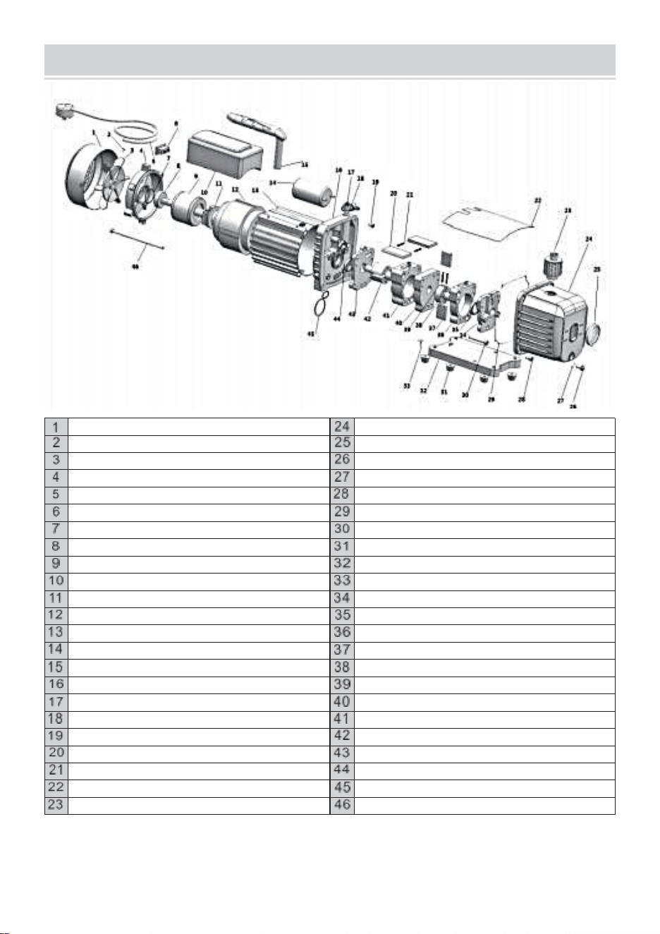
EXPLODED DRAWING
Fancover
Die-cast aluminum housing
Crossscrew
Sight glass
Fan
Oil drain
Motor cover
Oil drain screw O- ring
Power supply cords
Screw
Power switch
Sealing ring
Washer
Screw
Bearing
Rubber foot
Motor rotor
Base plate
Capacitor box
Self-tapping screw
Centrifugal switch
Back-pumpcover
Motor stator
Oil seal
Casing
Back-pump body
Capacitor
Back-rotary -vane
Handle
Back-pump rotor
Trestle
Spring
Gas cap
Middle fence
The air inlet nozzle
Front-pump body
Screw
Front- pump rotor
Front rotary-vane
Front cover
Spring
Oil seal
Cap board
O type ring
Exhaust and oil inlet fitting
Screw
Manufacturer: WENLING HONGBAOSHI VACUUM EQUIPMENT CO.,LTD
Address :Yaque Industrial Zone, Xinhe Town, Wenling City, Zhejiang Province


Technique Certificat d'assistance et de garantie électronique
www.vevor.com/support
POMPE A VIDE
GROUPE DE COMPTEURS DE
RÉFRIGÉRANT
MODÈLE : RS-0.5, RS-1, RS-1.5, RS-2
We continue to be committed to provide you tools with competitive price.
"Save Half", "Half Price" or any other similar expressions used by us only represents an
estimate of savings you might benefit from buying certain tools with us compared to the
major top brands and does not necessarily mean to cover all categories of tools offered by
us. You are kindly reminded to verify carefully when you are placing an order with us if you
are actually saving half in comparison with the top major brands.

- 1 -
MODÈLE : RS-0.5, RS-1, RS-1.5, RS-2
Have product questions? Need technical support? Please feel free to
contact us:
Technical Support and E-Warranty Certificate
www.vevor.com/support
NEED HELP? CONTACT US!
This is the original instruction, please read all manual instructions
carefully before operating. VEVOR reserves a clear interpretation of our
user manual. The appearance of the product shall be subject to the
product you received. Please forgive us that we won't inform you again if
there are any technology or software updates on our product.
VACUUM PUMP
REFRIGERANT METER GROUP
- 2 -
SAFETY INSTRUCTION
Avanten fonctionnementceappareil, s'il te plaît lire le instructionsmanuel
soigneusement et sauvegardercesinstructions. Basiquesécurité
précautionsdevraittoujoursêtresuivi, y comprisle suivant :
Avertissement -Àréduire le risque de blessure, l'utilisateur
doit lire les instructionsmanuel soigneusement.ed
Cesymbole, placé avant un commentaire de sécurité, indique un
type de précaution, avertissement ou danger. Ignorer cet
avertissement peut conduire à unaccident .Pour réduire le
risque de blessure, d’incendie ou d’électrocution, s'il te plaît
toujourssuivez la recommandation ci-dessous.
AVERTISSEMENT
Ménage Utiliser Seulement.
AVERTISSEMENT : Chaud Surface - À réduire le risque de brûlures , faire pas
touche .
ATTENTION : Pour réduire le risque de choc électrique, ne pas exposer à la pluie.
Conserver à l'intérieur. ATTENTION : Pour réduire le risque de électrique choc ,
utiliser uniquement à l'intérieur.
AVERTISSEMENT : Risque de blessure - Faire pas direct air vapeur à le corps .
Utiliser z seulement des ménages .
AVERTISSEMENT:Surface chaude-Pour reduire le risque de brolures,ne touchez pas.
ATTENTION: Pour reduire le risque de choc electrique, ne pas exposer a la pluie.
Stockez indoorsduce100
ATTENTION: Pour reduire le risque de choc electrique, utilisez uniquement a linter-
ieur.AVERTISSEMENT:RIsquedeblessure-Ne pas courant dair directe sur le corps.

- 3 -
PUMP COMPONENTS
OPERATING MANUAL
1.Before using your vacuum pump
Dans tous boîtiers , moteurs sont conçu pour en fonctionnement tensions plus ou
moins 1 0 % de le
normale note . Célibataire tension moteurs sont fourni pleinement connecté et prêt à
opérer .
( 1 ) Vérifier à être bien sûr le tension et fréquence à le sortie correspondre le
spécification -
tions sur le pompe moteur décalque . Vérifier le MARCHE - ARRÊT changer à être bien
sûr il est dans le DÉSACTIVÉ
position avant toi prise le pompe dans un prise . Supprimer et jeter le
échappement
capuchon depuis le fin de le pompe poignée .
( 2 ) Le pompe est expédié sans huile dans le réservoir . Avant départ le pompe ,
remplir
il avec huile . Supprimer le Échappement Convenable capuchon et ajouter huile jusqu'à
le huile juste spectacles dans le
bas de le vue verre . Le approximatif huile capacité de le pompe est
1 8 0 ~ 8 0 0 ml ( référence le technique données ) .
( 3 ) Remplacer le Échappement Convenable capuchon et retirer le capuchon depuis
un de le entrée
ports . Tourner le moteur changer à SUR . Quand le pompe s'exécute en douceur ,
remplacer le capuchon
sur le entrée port . Ceci peut prendre depuis deux jusqu'à 3 0 secondes , selon sur le
ambiant
température . Après le pompe s'exécute pour environ un minute , vérifier le vue
verre pour le approprié huile niveau . Le niveau devrait être même avec le vue verre
huile niveau

- 4 -
ligne . Ajouter huile si nécessaire.
Remarque : Lorsque le pompe est en cours d'exécution , le huile niveau devrait
être même avec le doubler sur
le vue verre . Sous-remplissage volonté résultat dans pauvre vide performances .
Surremplissage peut
résultat dans huile souffler depuis le échappement .

- 5 -
2. À fermer vers le bas ton pompe après utiliser
À aide prolonger pompe vie et promouvoir facile commencer . Suivre ces procédures
pour fermer vers le bas .
( 1 ) Fermer le collecteur soupape entre le pompe et le système .
( 2 ) Supprimer le tuyau depuis le pompe entrée .
( 3 ) Casquette le entrée port à prévenir n'importe lequel contamination ou lâche
particules depuis entrer
le port .
TO MAINTAIN YOUR HIGH VACUUM PUMP
1. Vide pompe huile :
Le condition et le type d'huile utilisé dans toute pompe à vide élevé est
extrêmement important dans déterminer le ultime vide atteignable. Nous
recommandons l'utilisation de HautVide PompeHuile . Cecihuile a a été
spécifiquement mélangé pour maintenir un maximum viscosité à des températures
de fonctionnement normales et pour améliorer les démarrages par temps froid.
2. Huile Changement Procédure
( 1 ) Être bien sûr le pompe est réchauffé en haut .
( 2 ) Supprimer le HUILE VIDANGE bouchon . Vidange contaminé huile dans un
approprié récipient
et disposer de il correctement . Huile peut être forcé à partir de la pompe en
ouvrant l'entrée et partiellement blocage le échappement avec un tissu
pendant que la pompe fonctionne. Ne pas faire fonctionner la pompe
pendant plus de 20 secondes en utilisant cette méthode .
( 3) Quand le couler de huile a arrêté , incliner le pompe avant à vidange résiduel
huile .
( 4 ) Remplacer le HUILE VIDANGE capuchon . Retirer le échappement
convenable et remplir le réservoir
avec nouveau vide pompe huile jusqu'à le huile juste spectacles à le bas de le vue
verre . Le approximatif huile capacité de la pompe est de 180 à 800 ml (référez-vous
à la fiche technique données ) .
( 5) Assurez-vous que les ports d'entrée sont bouchés, puis allumez la pompe.
Laissez-la fonctionner pendant un minute , alors vérifier l'espace de niveau d'huile.
Si l'huile est en dessous du voyant HUILE NIVEAU ligne , ajouter huile
lentement ( avec le pompe en cours d'exécution )jusqu'à ce que l'huile atteigne
l'HUILE NIVEAU ligne . Remplacer le échappement montage, en s'assurant
que l'entrée est
( 6)
a )Silehuile estgravement contaminé par des boues qui se forment lorsque
l'eau est autorisée à collecterdanslehuile , vous devrez peut-être retirer le
couvercle du réservoir d'huile et essuyer il dehors.

- 6 -
b )Un autreLa méthode de traitement du pétrole fortement contaminé consiste à
forcer le pétrole à sortir. lepomperéservoir . Pour ce faire, laissez la pompe
fonctionner jusqu'à ce qu'elle soit chaude. Pendant que la la pompe fonctionne
toujours, retirez le bouchon de vidange d'huile. Limitez légèrementl'échappement. Cela
permettra de pressionlehuileréservoiretforcer le l'huile qui en sort, transportant
davantage de contamination.
Quand l'huile cesse à couler , tourner désactivé le pompe .
Répétez cette procédure autant de fois que nécessaire jusqu’à ce que la
contamination soit éliminée .
RemplacerleBouchon deVIDANGE D'HUILE et remplissez leréservoir
jusqu'au niveau approprié avec frais pompe à huile.

- 7 -
TROUBLESHOOTING GUIDE
Votre pompe est conçue pour une utilisation fiable et a une longue durée de vie.
Si quelque chose devait aller faux, le guide suivant vous aidera à remettre la
pompe en service le plus rapidement possible comme possible.
Siledémontage de la pompe est nécessaire, veuillez vérifier votre garantie.La
garantie peut être annulé par mauvaise utilisation ou altération par le client, ce qui
entraîne la panne de la pompe inutilisable .
1. Échec À Commencer
Vérifier la tension de ligne. La pompe doit démarrer à ±10 % de la tension de
ligne (chargée) à 320 °F. Dans les cas extrêmes, une commutation entre les
enroulements de fonctionnement standard peut se produire .
2. Huile fuite
( 1 ) Être bien sûr le huile est pas un résiduel accumulation depuis déversement ,
etc.
( 2 ) Si fuite existe , le module couverture joint d'étanchéité ou le arbre joint peut
besoin remplaçant .
S'il y a une fuite dans le zone de le huile vidange branchez , vous peut besoin à
refermer le prise en utilisant un commercial tuyau fil scellant .
3. Échec À Tirer UN Bien Vide
(1) Assurez-vous que la jauge à vide et toutes les connexions sont en bon
état et sans fuite. Vous pouvez confirmer la fuite en surveillant le vide avec une
jauge à thermistance lors de l'application d'huile de pompe à vide au niveau des
raccords ou des points de fuite suspects. Le vide s'améliorera brièvement
pendant que l'huile scelle la fuite.
(2) Assurez-vous que l'huile de la pompe est propre. Une pompe très
contaminée peut nécessiter plusieurs vidanges d'huile.
(3) Assurez-vous que l'huile est au niveau approprié. Pour un
fonctionnement optimal de la pompe, l'huile doit être au même niveau que la
ligne de NIVEAU D'HUILE sur le voyant lorsque la pompe fonctionne. Ne
remplissez pas trop : les températures de fonctionnement provoqueront une
expansion de l'huile, de sorte qu'elle apparaîtra à un niveau plus élevé que
lorsque la pompe ne fonctionne pas. Pour vérifier le niveau d'huile, démarrez la
pompe. pompe avec l'entrée bouchée. Contrôler le niveau d'huile dans le voyant.
Ajouter de l'huile si nécessaire.

- 8 -
COMMUN INQUIÉTERTOURNAGE
Échec
Description
FauteCause
Solution
Faiblevide
1. Le bouchond'entrée d'air surle
port derechange côté de le l'orifice
d'admission d'air est desserré.
Serrer le bouchon d'admission
d'air
2.L'anneau en caoutchouc à
l'intérieur de l'air entrée
capuchon sur le côté bâbord de
secours le air entrée le port est
endommagé
Remplacer leanneau en
caoutchouc
3.Manque d' huile
Ravitailler à le ligne médiane de le
huile
jauge
4. L'huile delapompe est
émulsionnée et impur
Remplaceravecnouvelle huile
5.Letroud'admission d'huile
de la pompe est bloqué ou le
l'approvisionnement en pétrole
est je suis insuffisant
Nettoyez l'orifice d'admission
d'huile et le filtre engrener
6.Fuitedu conteneur de
tuyau connecté à la pompe
Vérifierletuyau connecté
récipient à éviter les fuites
7.Sélectionde pompe inappropriée
Vérifiez la taille de la pompe
conteneur, recalculer et
sélectionner le modèle de
pompe approprié
8. La pompe a été utilisée pour
longue , et le le dédouanement est
augmenté exigible à l'usure des
pièces
Vérifiez ,réparez ou
remplacez le pompe avec
un nouveau sur e
HuileFuite
1.Lejoint d'huile estendommagé
Remplacerlejointd'étanchéité
2.Le raccordement du réservoir
d'huile est
lâcheouendommagé
Serrez les vis et remplacez -
les. le Joint torique
Injection d'huile
1.Tropd'huile
Vidange le huile à le ligne de
niveau d'huile
2.Le la pression d'admission
esttrop élevée pour il y a
longtemps
Sélectionner leapproprié
pomper à augmenter la vitesse
de pompage
1. La température de l'huile est
aussi faible
Leair l'entrée est ventilée,
démarre le moteur à
plusieurs reprises ou chauffe

- 9 -
Démarrage
difficile
la pompe à huile
2.Le moteur ou l'alimentation
est défectueux
Vérifieretréparer
3.Étranger les objets
tombent dans le pompe
Vérifieret éliminer
4.La tension d'alimentation est
aussi faible
Vérifierlatension d'alimentation
Note:Si leau-dessusdesolutionsfaire pasrésoudre tonproblème,s'ilte plaît contact le le
plusprocherevendeur,ou envoyertonpompeà unprofessionnel réparation centre,et
nousvolonté fairenotre meilleurà servirtoi.
Groupe de compteurs de réfrigérant
MODE D'EMPLOI
Opération Instructions
Avant la connexion, il faut vérifier si les manomètres indiquent zéro. Si ce n'est pas le
cas, ajustez la vis de réglage du manomètre pour régler l'aiguille sur zéro.
Connexion système
Tout d’abord, fermez les vannes haute pression et basse pression.
Connectez et fixez le port basse pression - tube bleu - (connecteur rapide basse
pression) - côté basse pression du système.
(Connectez et fixez le port haute pression - tube rouge - (connecteur rapide haute
pression) - côté haute pression du système.)
Connectez et fixez le port de remplissage - tube jaune - (pompe à vide).
Système de vide ou de récupération
(Attention : pour un système sûr et des économies d'énergie, il faut sélectionner une
pompe à vide ou une unité de récupération appropriée en fonction de la pression du
système)
Une fois la connexion mentionnée ci-dessus terminée, démarrez d’abord la pompe à
vide ou l’unité de récupération.
Ouvrez simultanément la vanne haute pression et la vanne basse pression, puis
(ouvrez les connecteurs rapides haute pression et basse pression), le système
commence à aspirer ou à récupérer.
Après un certain temps (environ 10 à 30 minutes), vérifiez
si le système est aspiré. (1f le système
n'est pas aspiré, il faut vérifier s'il y a une fuite dans
le système et le vider à nouveau une fois le problème de fuite résolu.)
Fermez simultanément la vanne haute pression et la vanne basse pression.
Enfin, fermez la pompe à vide ou l’unité de récupération.

- 10 -
Maintenez la pression pendant 3 à 5 minutes pour vérifier s'il y a une fuite dans le
système.
Recharge de réfrigérant
Connectez le tube jaune à la bouteille de réfrigérant. Ouvrez d'abord la bouteille de
réfrigérant (position verticale normale), puis ouvrez la vanne à l'intérieur de l'ensemble
de jauge pour purger l'air du tube jaune. Inversez la bouteille de réfrigérant et placez-
la bien. Injectez le réfrigérant dans la vanne haute pression jusqu'à la quantité
spécifiée (selon les spécifications de remplissage du fabricant). Fermez la
vanne haute pression et placez la bouteille de réfrigérant dans sa position verticale
normale.
Confirmer l'effet de remplissage
Démarrez d’abord le fonctionnement du système.
Après un certain temps (environ 5 à 10 minutes), vérifiez si la basse et la haute
pression du système sont toutes deux dans des conditions normales. Si la pression
du système est insuffisante, il faut
ouvrir lentement la vanne basse pression (ne pas ouvrir la vanne haute pression pour
le moment). Après avoir ajouté une quantité appropriée de réfrigérant gazeux
(bouteille en acier dans sa position verticale normale), fermer la vanne basse
pression et vérifier
le système à nouveau.
Maintenance et sécurité
N'exercez jamais une force excessive pour ouvrir ou fermer les vannes, sinon
l'élément d'étanchéité risque d'être endommagé.
Suivez toujours les instructions d'utilisation ou utilisez-le sous la direction d'un
spécialiste.
Ne jamais abuser de la haute pression et de la basse pression .
N'ouvrez jamais simultanément la vanne haute pression et la vanne basse pression
pendant l'opération de remplissage.
Ne jamais utiliser un fluide de travail non conforme à l'indication portée sur le
manomètre.
Ne laissez jamais le viseur pointer vers une personne afin d'éviter tout accident.
Les manomètres sont des pièces d'usure et nécessitent un étalonnage périodique.
Pour une bonne précision, il faut normalement livrer les manomètres à
l'autorité pour l'étalonnage tous les 3 à 6 mois.

- 11 -
Utilisez-les toujours avec précaution et protégez-les des vibrations ou des chutes
accidentelles.
Après utilisation, les valves doivent être relâchées et maintenues
l'instrument bien rangé.

- 12 -
TECHNICAL PARAMETER
UGS
ACKDZKB235CFM9U8YV3
Modèle
RS-1
Tension
220-240 V 50 Hz
Déplacement d'air libre
3,5 pi3/min
Vide ultime
5PA
Vitesse de rotation
1440
Puissance (HP)
1/4
Capacité d'huile (ml)
220
Dimension (mm)
240*110*220
Poids (kg)
7
Accessoire
Groupe de compteurs de réfrigérant
Champ d'application : R22 R134A R410A R404A
Trois tuyaux de 48 pouces de long
1 paire de connecteurs rapides pour climatisation de voiture
1 paire d'adaptateur 410A
UGS
3CFM1-4HPZKBZJOC1V2
3CFM1-4HPZKBZJ001V3
Modèle
RS-1
Tension
220-240 V 50 Hz
Déplacement d'air libre
3 pi3/min
Vide ultime
5PA
Vitesse de rotation
1440
Puissance (HP)
1/4
Capacité d'huile (ml)
220
Dimension (mm)
240*110*220
Poids (kg)
6.8
Accessoire
Groupe de compteurs de réfrigérant
Champ d'application : R22 R134A R410A
Trois tuyaux de 36 pouces de long
1 paire de connecteurs rapides pour climatisation de voiture
UGS
1,8 pi3/min1-4HPZKBZJ1V2
Modèle
RS-0,5
Tension
220-240 V 50 Hz
Déplacement d'air libre
1,8 pi3/min
Vide ultime
5PA
Vitesse de rotation
1440
Puissance (HP)
1/4
Capacité d'huile (ml)
220
Dimension (mm)
240*110*220
Poids (kg)
6.8
Accessoire
Groupe de compteurs de réfrigérant
Champ d'application : R22 R134A R410A
Trois tuyaux de 36 pouces de long
1 paire de connecteurs rapides pour climatisation de voiture

- 13 -
UGS
4CFM1/4HPZKB1F001V2
4CFM1/4HPZKB1F001V3
Modèle
RS-1.5
Tension
220-240 V 50 Hz
Déplacement d'air libre
4 pi3/min
Vide ultime
5PA
Vitesse de rotation
1440
Puissance (HP)
1/3
Capacité d'huile (ml)
225
Dimension (mm)
270*110*220
Poids (kg)
7.6
Accessoire
Groupe de compteurs de réfrigérant
Champ d'application : R134A
Trois tuyaux de 36 pouces de long
1 paire de connecteurs rapides pour climatisation de
voiture
UGS
4CFM1/4HPZKB1F001V1
Modèle
RS-1.5
Tension
120V/60HZ
Déplacement d'air libre
4 pi3/min
Vide ultime
5PA
Vitesse de rotation
1720
Puissance (HP)
1/3
Capacité d'huile (ml)
225
Dimension (mm)
270*110*220
Poids (kg)
7.6
Accessoire
Groupe de compteurs de réfrigérant
Champ d'application : R134A
UGS
3CFM1-4HPZKBZUMC1V1
Modèle
RS-1
Tension
120V/60HZ
Déplacement d'air libre
3 pi3/min
Vide ultime
5PA
Vitesse de rotation
1720
Puissance (HP)
1/4
Capacité d'huile (ml)
220
Dimension (mm)
240*110*220
Poids (kg)
6.8
Accessoire
Groupe de compteurs de réfrigérant
Champ d'application : R22 R134A R410A
Trois tuyaux de 36 pouces de long
1 paire de connecteurs rapides pour climatisation de
voiture

- 14 -
Trois tuyaux de 36 pouces de long
1 paire de connecteurs rapides pour climatisation de voiture

- 15 -
UGS
4CFM1/3HPZKB4F001V2
Modèle
RS-1.5
Tension
220-240 V 50 Hz
Déplacement d'air libre
4 pi3/min
Vide ultime
5PA
Vitesse de rotation
1440
Puissance (HP)
1/3
Capacité d'huile (ml)
225
Dimension (mm)
270*110*220
Poids (kg)
7.6
Accessoire
Groupe de compteurs de réfrigérant
Champ d'application : R22 R12 R134A R502
Trois tuyaux de 36 pouces de long
1 paire de connecteurs rapides pour climatisation de voiture
1 paire d'adaptateur 410A
UGS
MCKDZK44.8CFM7CNVV1
Modèle
RS-2
Tension
120V/60HZ
Déplacement d'air libre
4,8 pi3/min
Vide ultime
5PA
Vitesse de rotation
1720
Puissance (HP)
1/3
Capacité d'huile (ml)
250
Dimension (mm)
290*120*230
Poids (kg)
9.3
Accessoire
Groupe de compteurs de réfrigérant
Champ d'application : R410A R22 R134A R404A
Quatre tuyaux de 60 pouces de long
1 paire de connecteurs rapides pour climatisation de
voiture
1 paire d'adaptateur 410A
UGS
MCKDZK43.6CFM6DQYV1
Modèle
RS-1
Tension
120V/60HZ
Déplacement d'air libre
3,6 pi3/min
Vide ultime
5PA
Vitesse de rotation
1720
Puissance (HP)
1/4
Capacité d'huile (ml)
220
Dimension (mm)
240*110*220
Poids (kg)
8
Accessoire
Groupe de compteurs de réfrigérant
Champ d'application : R410A R22 R134A R404A
Quatre tuyaux de 60 pouces de long
1 paire de connecteurs rapides pour climatisation de
voiture

- 16 -
1 paire d'adaptateur 410A
1 ouvre-bouteille
1 trousse à outils
UGS
4,8 pi3/min1/3 HPZKB3F1V2
4,8 pi3/min1/3 HPZKB3F1V3
Modèle
RS-2
Tension
220-240 V 50 Hz
Déplacement d'air libre
4,8 pi3/min
Vide ultime
5PA
Vitesse de rotation
1440
Puissance (HP)
1/3
Capacité d'huile (ml)
250
Dimension (mm)
290*120*230
Poids (kg)
8.6
Accessoire
Groupe de compteurs de réfrigérant
Champ d'application : R22 R134A R410A
Trois tuyaux de 36 pouces de long
1 paire de connecteurs rapides pour climatisation de
voiture
UGS
4,8 pi3/min1/3 HPZKB3F1V1
Modèle
RS-2
Tension
120V/60HZ
Déplacement d'air libre
4,8 pi3/min
Vide ultime
5PA
Vitesse de rotation
1720
Puissance (HP)
1/3
Capacité d'huile (ml)
250
Dimension (mm)
290*120*230
Poids (kg)
8.6
Accessoire
Groupe de compteurs de réfrigérant
Champ d'application : R22 R134A R410A
Trois tuyaux de 36 pouces de long
1 paire de connecteurs rapides pour climatisation de
voiture
UGS
MCKDZK44.8CFM7CNVV2
Modèle
RS-2
Tension
220-240 V 50 Hz
Déplacement d'air libre
4,8 pi3/min
Vide ultime
5PA
Vitesse de rotation
1440
Puissance (HP)
1/3
Capacité d'huile (ml)
250
Dimension (mm)
290*120*230
Poids (kg)
8.6
Accessoire
Groupe de compteurs de réfrigérant
Champ d'application : R410A R22 R134A R404A

- 17 -
Quatre tuyaux de 60 pouces de long
1 paire de connecteurs rapides pour climatisation de
voiture
1 paire d'adaptateurs 410A
- 18 -
EXPLODED DRAWING
Couvercleduventilateur
Moulé sous pression boîtier en aluminium
Croix vis
Vue verre
Ventilateur
Huile vidange
Moteur couverture
Huile vidange vis Jo i n t torique
Cordons d'alimentation
Vis
Interrupteur d'alimentation
Scellage anneau
Rondelle
Vis
Palier
Caoutchouc pied
Moteur rotor
Plaque de base
Condensateur boîte
Autotaraudage vis
Centrifuge changer
Couvercledepompe arrière
Moteur stator
Huile joint
Boîtier
Retour - pompe corps
Ca Paciteur
Arrière - rotatif - à palettes
Poignée
Retour - pompe rotor
Tre style
Printemps
Gaz capuchon
Milieu clôture
L' air entrée ajutage
Avant - pompe corps
Vis
Avant - pompe rotor
Devant à palettes rotatives
Couverture avant
Printemps
Huile joint
Ca p conseil
O taper anneau
Échappement et huile entrée convenable
Vis
Fabricant : WENLING HONGBAOSHI VACUUM EQUIPMENT SOCIÉTÉ, LTD.
Adresse : Zone industrielle de Yaque, ville de Xinhe, ville de Wenling, province du
Zhejiang


Technisch Support und E-Garantie-Zertifikat
www.vevor.com/support
VAKUUMPUMPE
KÄLTEMITTELZÄHLERGRUPPE
MODELL: RS-0.5, RS-1, RS-1.5, RS-2
We continue to be committed to provide you tools with competitive price.
"Save Half", "Half Price" or any other similar expressions used by us only represents an
estimate of savings you might benefit from buying certain tools with us compared to the
major top brands and does not necessarily mean to cover all categories of tools offered by
us. You are kindly reminded to verify carefully when you are placing an order with us if you
are actually saving half in comparison with the top major brands.

- 1 -
MODELL: RS-0.5, RS-1, RS-1.5, RS-2
Have product questions? Need technical support? Please feel free to
contact us:
Technical Support and E-Warranty Certificate
www.vevor.com/support
NEED HELP? CONTACT US!
This is the original instruction, please read all manual instructions
carefully before operating. VEVOR reserves a clear interpretation of our
user manual. The appearance of the product shall be subject to the
product you received. Please forgive us that we won't inform you again if
there are any technology or software updates on our product.
VACUUM PUMP
REFRIGERANT METER GROUP

- 2 -
SAFETY INSTRUCTION
VorBetriebsDasGerät,BittelesenDieAnweisungenHandbuchsorgfältig
Und speicherndieseAnweisungen.BasicSicherheitVorsichtsmaßnahmen
sollenstetsSeigefolgt, einschließlichDie Folgendes:
Warnung -Anreduzieren Um die Gefahr von Verletzungen
zu vermeiden, muss der Benutzer die Anweisungen
Handbuch sorgfältig durch.
DasDas Symbol vor einem Sicherheitshinweis weist auf eine Art
Vorsichtsmaßnahme, Warnung oder Gefahr. Das Ignorieren
dieser Warnung kann zu einUnfall .Um das Risiko von
Verletzungen, Bränden oder Stromschlägen zu verringern,
BittestetsBefolgen Sie die unten aufgeführte Empfehlung.
WARNUNG
Haushalt Verwenden Nur.
WARNUNG : Heiß Oberfläche - Bis reduzieren Die Risiko von Verbrennungen , tun
nicht berühren .
ACHTUNG : reduzieren Die Stromschlaggefahr, nicht dem Regen aussetzen. Im
Innenbereich lagern. ACHTUNG : reduzieren Die Risiko von elektrisch Schock ,
nur in Innenräumen verwenden.
WARNUNG : Risiko von Verletzung - Tun nicht direkt Luft Dampf bei Die Körper .
Nutzen Sie z nur des Ménages .
ACHTUNG : Oberfläche heiß - Für Reduzieren Sie das Risiko von Verbrennungen,
nicht berühren. ACHTUNG : Für reduzieren DER Risiko von Schock elektrisch , nicht
nicht dem Regen aussetzen.
Speichern Indoorduce 1 00
VORSICHT: Um das Risiko eines Stromschlags zu verringern, verwenden Sie nur
einen Linte r - ieur .WARNUNG :RISIKOvonVerletzungen –Luftzug nicht direkt auf
den Körper richten.

- 3 -
PUMP COMPONENTS
OPERATING MANUAL
1.Vorher verwenden dein Vakuum Pumpe
In alle Gehäuse , Motoren Sind entworfen für Betriebs Spannungen Plus oder minus
1 0 % von Die
Normal Bewertung . Einzeln Stromspannung Motoren Sind mitgeliefert voll verbunden
Und bereit Zu
bedienen .
( 1 ) Prüfen Zu Sei Sicher Die Stromspannung Und Frequenz bei Die Auslauf
übereinstimmen Die Spezifikationen -
tionen An Die Pumpe Motor Aufkleber . Überprüfen Die EIN - AUS schalten Zu Sei
Sicher Es Ist In Die AUS
Position vor Du Stecker Die Pumpe hinein ein Steckdose . Entfernen Und verwerfen
Die Auspuff
Kappe aus Die Ende von Die Pumpe handhaben .
( 2 ) Die Pumpe Ist versendet ohne Öl In Die Reservoir . Vor ab Die Pumpe ,
füllen
Es mit Öl . Entfernen Die Auspuff Beschlag Kappe Und hinzufügen Öl bis Die Öl Nur
zeigt In Die
unten von Die Sicht Glas . Das ungefähr Öl Kapazität von Die Pumpe Ist
1 8 0 ~ 8 0 0 ml ( Referenz Die technisch Daten ) .
( 3 ) Ersetzen Die Auspuff Beschlag Kappe Und entfernen Die Kappe aus eins von
Die Einlass
Häfen . Drehen Die Motor schalten Zu EIN . Wenn Die Pumpe Läuft reibungslos ,
ersetzen Die Kappe
An Die Einlass Port . Diese Mai nehmen aus zwei bis 3 0 Sekunden , abhängig An Die
Umgebungstemperatur
Temperatur . Nach Die Pumpe Läuft für etwa eins Minute , überprüfen Die Sicht

- 4 -
Glas für Die richtig Öl Ebene . Die Ebene sollen Sei sogar mit Die Sicht Glas Öl
Ebene
Zeile . Hinzufügen Öl wenn nötig.
Hinweis : Wenn Die Pumpe Ist Laufen , das Öl Ebene sollen Sei sogar mit Die
Linie An
Die Sicht Glas . Unterfüllung Wille Ergebnis In arm Vakuum Leistung . Überfüllung
dürfen
Ergebnis In Öl Blasen aus Die Auspuff .

- 5 -
2. Zu schließen runter dein Pumpe nach verwenden
Zu helfen verlängern Pumpe Leben Und fördern einfach starten . Folgen diese
Verfahren
für schließen runter .
( 1 ) Schließen Die vielfältig Ventil zwischen Die Pumpe Und Die .
( 2 ) Entfernen Die Schlauch aus Die Pumpe Einlass .
( 3 ) Kappe Die Einlass Hafen Zu verhindern beliebig Kontamination oder lose
Partikel aus Eingabe
Die Hafen .
TO MAINTAIN YOUR HIGH VACUUM PUMP
1.Vakuum Pumpe Öl :
Der Zustand Und Die in Hochvakuumpumpen verwendeten Öle sind extrem
wichtig In bestimmend Die ultimative erreichbares Vakuum. Wir empfehlen die
Verwendung von Hoch Vakuum Pumpe Öl .DiesÖl hat wurde speziell gemischt, um
maximale Viskosität bei normalen Betriebstemperaturen und zur Verbesserung
des Starts bei kaltem Wetter.
2. Öl Ändern Verfahren
( 1 ) Sei Sicher Die Pumpe Ist erwärmt hoch .
( 2 ) Entfernen Die ÖL ABFLUSS Kappe . Ablassen kontaminiert Öl hinein A
geeignet Container
Und entsorgen von Es richtig . Öl kann durch Öffnen des Einlasses aus der
Pumpe gedrückt werden Und teilweise Blockierung Die Auspuff mit A Tuch
während die Pumpe läuft. Betreiben Sie die Pumpe mit dieser
Methode nicht länger als 20 Sekunden .
( 3) Wenn Die fließen von Öl hat gestoppt , kippen Die Pumpe nach vorne Zu
Abfluss Rest Öl .
( 4 ) Ersetzen Die ÖL ABFLUSS Kappe . Entfernen Die Auspuff Beschlag Und
füllen Die Reservoir
mit neu Vakuum Pumpe Öl bis Die Öl Nur zeigt bei Die unten von Die Sicht
Glas . Das ungefähr Öl Kapazität der Pumpe beträgt 180-800ml (siehe technische d
aten ).
( 5)Stellen Sie sicher, dass die Einlassöffnungen verschlossen sind, und
schalten Sie dann die Pumpe ein. Lassen Sie sie eins Minute , dann überprüfen
der Ölstandraum. Wenn der Ölstand unterhalb des Schauglases OEL liegt
EBENE Zeile , hinzufügen Öl langsam ( mit Die Pumpe läuft )bis das Öl die ÖL-
Markierung erreicht EBENE Zeile . Ersetzen Die Auspuff und achten Sie
darauf, dass der Einlass
( 6)

- 6 -
a )Wenn Die Öl Istschlecht kontaminiert mit Schlamm, der entsteht, wenn
Wasser Zusammeln InDieÖl , müssen Sie möglicherweise die
Ölbehälterabdeckung entfernen und abwischen Es aus.
b )Ein anderer Die beste Methode, um stark verunreinigtes Öl zu behandeln,
besteht darin, das Öl aus DiePumpe Vorratsbehälter .Lassen Sie dazu die Pumpe
laufen,bis sie warm ist. Während der Pumpe noch läuft, entfernen Sie die
Ölablasskappe. Drosseln Sie den Auspuff leicht . Dadurch wird Druck DieÖl Reservoir
Und GewaltDie Öl daraus, das weitere Verunreinigungen mit sich bringt.
Wenn das Öl nachlässt Zu fließen , wenden aus Die Pumpe .
Wiederholen Sie diesen Vorgang nach Bedarf, bis die Verschmutzung beseitigt ist .
ErsetzenDie ÖLABLASS-Kappe und füllen Sie den Behälter bis zum
richtigen Stand mit frisch Öl pumpen.

- 7 -
TROUBLESHOOTING GUIDE
Ihre Pumpe ist zuverlässig im Einsatz und hat eine lange Lebensdauer. Sollte
etwas gehen falsch, die folgende Anleitung wird Ihnen helfen, die Pumpe so
schnell wie möglich wieder in Betrieb zu nehmen als möglich.
Wenn Die Demontage der Pumpe erforderlich ist, überprüfen Sie bitte Ihre
Garantie.Die Garantie Mai Sei ungültig von Missbrauch oder Manipulation durch den
Kunden, die dazu führen, dass die Pumpe nicht funktionsfähig .
1. Fehler Zu Start
Überprüfen die Netzspannung. Die Pumpe muss bei ±10 % Netzspannung
(unter Last) starten bei 320 °F. In Extremfällen kann es zu einem Umschalten
zwischen den Standardwicklungen kommen .
2. Öl Leckage
( 1 ) Sei Sicher Die Öl Ist nicht A Rest Akkumulation aus Verschütten usw.
( 2 ) Wenn Leckage existiert , die Modul Abdeckung Dichtung oder Die Welle Siegel
Mai brauchen ersetzen .
Bei Undichtigkeiten in Die Bereich von Die Öl Abfluss Stecker , Sie Mai
brauchen Zu wieder verschließen Die Stecker mit A kommerziell Rohr Faden
Versiegelung .
3. Scheitern Zu Ziehen A Gut Vakuum
(1) Stellen Sie sicher, dass das Vakuummeter und alle Anschlüsse in gutem
Zustand und dicht sind. Sie können Leckagen feststellen, indem Sie das
Vakuum mit einem Thermistormessgerät überwachen. während Sie
Vakuumpumpenöl auf Verbindungen oder vermutete Leckstellen auftragen. Das
Vakuum wird sich kurzzeitig verbessern, während das Öl das Leck abdichtet.
(2) Stellen Sie sicher, dass das Pumpenöl sauber ist. Bei stark verschmutzter
Pumpe sind möglicherweise mehrere Ölspülungen erforderlich.
(3) Stellen Sie sicher, dass der Ölstand richtig ist. Für einen optimalen
Pumpenbetrieb muss der Ölstand bei laufender Pumpe auf gleicher Höhe mit
der Ölstandslinie am Schauglas sein. Überfüllen Sie nicht – bei
Betriebstemperaturen dehnt sich das Öl aus, sodass der Ölstand höher ist als
bei ausgeschalteter Pumpe. Um den Ölstand zu prüfen, starten Sie die Pumpe
mit verschlossenem Einlass. Überprüfen Sie den Ölstand im Schauglas. Füllen
Sie bei Bedarf Öl nach.

- 8 -
GEMEINSAM PROBLEMSCHIESSEN
Versagen
Beschreibung
FehlerUrsache
Lösung
NiedrigesVakuum
1. Die Lufteinlasskappe am
Ersatzanschluss Seite von Die Der
Lufteinlassanschluss ist locker.
Anziehen Die Lufteinlasskappe
2.Der Gummiring im Luft
Einlass KappeAn die freie
Backbordseite von Die Luft
Einlass Port ist beschädigt
Ersetzen DieGummiring
3.Ölmangel
Tanken Zu Die Mittellinie von Die
Öl
Messgerät
4. Das Pumpenöl wird
emulgiert Und unrein
Ersetzenmit neues Öl
5.Die Öleinlassöffnung der
Pumpe Ist abgewehrt oderDie
Ölversorgung ist
unzureichend
Reinigen Sie die
Öleinlassöffnung und den
Filter Maschenware
6.Undichtigkeitdes
Rohrbehälters an die
Pumpe angeschlossen
ÜberprüfenDie
verbundenesRohr
ContainerZu Vermeidung
von Leckagen
7.Falsche Pumpenauswahl
Überprüfen Sie die Größe der
Pumpe d Container neu
berechnen und auswählen das
passende Pumpenmodell
8. Die Pumpe wurde verwendet,
um lang und Die Abstand ist
erhöht fällig zum Verschleiß von
Teilen
Überprüfen ,reparieren
oder ersetzen Sie die
Pumpemit einem neuen
aufe
Öl Leckage
1.Die Öldichtung ist beschädigt
ErsetzenDieÖldichtung
2.Der Öltankanschluss ist
loseoder beschädigt
DieSchrauben festziehen und
die Die O - Ring
Öleinspritzung
1.ZuvielÖl
Abfluss Die Öl ZuDie
Ölstandslinie
2.Die Eingangsdruck istzu
hoch für lange
Wählen Die geeignet Pumpe
zu ErhöhenSiedie
Pumpgeschwindigkeit d
1. Die Öltemperatur Ist zu niedrig
Der Luft Einlass ist belüftet,
startet wiederholt den Motor
oder heiztdas Pumpenöl

- 9 -
Schwerer Start
2.Der Motorbzw. das Netzteil
ist fehlerhaft
Überprüfen und Reparatur
3.Ausländische
Gegenstände fallen in den
Pumpe
Überprüfen und beseitigen
4.DieVersorgungsspannung
beträgt zu niedrig
Überprüfen die
Versorgungsspannung
Notiz:WennDie überLösungenTun nichtlösendeinProblem, BitteKontakt Die nächste
Händler,oder schickendeinPumpeZu A ProfessionalreparierenCenter, Und WirWille
Tununserambesten ZuAufschlag Du.
Kältemittelzählergruppe
GEBRAUCHSANWEISUNG
Betrieb Anweisungen
Vor dem Anschluss sollte geprüft werden, ob Die Druckmessgeräte zeigen Null an.
Wenn dies nicht der Fall ist, stellen Sie den Zeiger mit der Einstellschraube am
Druckmessgerät auf Null.
Systemanbindung
Schließen Sie zunächst sowohl das Hochdruck- als auch das Niederdruckventil.
Schließen Sie den Niederdruckanschluss – blaues Rohr – (Niederdruck-
Schnellanschluss) an und sichern Sie ihn – Niederdruckseite des Systems.
Den Hochdruckanschluss (roter Schlauch) (Hochdruck-Schnellanschluss)
anschließen und sichern (Hochdruckseite des Systems).
Den Nachfüllanschluss (gelber Schlauch) (Vakuumpumpe) anschließen und sichern.
Vakuumsystem oder Rückgewinnung
(Achtung: Für ein sicheres System und zur Energieeinsparung muss entsprechend
dem Systemdruck die richtige Vakuumpumpe oder Rückgewinnungseinheit
ausgewählt werden.)
Nachdem Sie die oben genannten Anschlüsse vorgenommen haben, starten Sie
zunächst die Vakuumpumpe oder die Rückgewinnungseinheit.
Öffnen Sie gleichzeitig das Hochdruckventil und das Niederdruckventil. (Öffnen Sie
dann sowohl die Hochdruck- als auch die Niederdruck-Schnellkupplung.) Das
System beginnt mit dem Vakuumieren oder der Rückgewinnung.
Nach einer gewissen Zeit (ca. 10- 30 Minuten) überprüfen
wenn das System abgesaugt wird. (1f das System
nicht abgesaugt ist, sollte überprüft werden, ob es ein Leck gibt in
das System und saugen Sie es erneut ab, nachdem das Leckageproblem behoben
wurde.)
Schließen Sie sowohl das Hochdruck- als auch das Niederdruckventil gleichzeitig.
Schließen Sie abschließend die Vakuumpumpe bzw. die Absaugeinheit.

- 10 -
Halten Sie den Druck 3–5 Minuten lang aufrecht, um zu prüfen, ob im System ein
Leck vorliegt.
NachfüllenKältemittel
Verbinden Sie den gelben Schlauch mit der Kältemittelflasche. Öffnen Sie zuerst die
Kältemittelflasche (normale aufrechte Position), und öffnen Sie dann das Ventil im
Inneren des Manometers, um die Luft aus dem gelben Schlauch zu entfernen.
Drehen Sie die Kältemittelflasche um und platzieren Sie sie gut. Spritzen Sie das
Kältemittel bis zur angegebenen Menge in das Hochdruckventil (gemäß der
Nachfüllspezifikation des Herstellers). Schließen Sie das
Hochdruckventil und stellen Sie die Kühlmittelflasche in ihre normale aufrechte
Position.
Nachfülleffekt bestätigen
Starten Sie zuerst den Systembetrieb.
Nach einer gewissen Zeit (ca. 5-10 Minuten) überprüfen Sie das System, ob sowohl
Niederdruck als auch Hochdruck im Normalzustand sind. Wenn der Systemdruck
nicht ausreicht, sollte er
Öffnen Sie langsam das Niederdruckventil (das Hochdruckventil darf im Moment
nicht geöffnet werden). Nachdem eine angemessene Menge gasförmigen
Kältemittels (Stahlflasche in ihrer normalen aufrechten Position) hinzugefügt wurde,
schließen Sie das Niederdruckventil und überprüfen Sie
das System erneut.
Wartung und Sicherheit
Überanstrengen Sie beim Öffnen bzw. Schließen der Ventile niemals Ihre Kraft, da
sonst das Dichtelement beschädigt werden kann.
Befolgen Sie stets die Bedienungsanleitung oder bedienen Sie das Gerät unter
Anleitung eines Fachmanns.
Missbrauchen Sie niemals den Hoch- und Niederdruck .
Öffnen Sie während des Nachfüllvorgangs niemals das Hochdruck- und das
Niederdruckventil gleichzeitig.
Verwenden Sie niemals Arbeitsmedien, die nicht der Angabe auf dem Manometer
entsprechen.
Um Unfälle zu vermeiden, richten Sie das Schauglas niemals auf Personen.
Die Druckmessgeräte sind Verschleißteile und müssen regelmäßig kalibriert werden.
Für eine gute Genauigkeit sollten die Messgeräte normalerweise an
die Stelle zur Kalibrierung alle 3-6 Monate.

- 11 -
Gehen Sie stets vorsichtig mit ihnen um und schützen Sie sie vor Erschütterungen
oder unachtsamem Herunterfallen.
Nach Gebrauch sollten die Ventile geöffnet und
das Instrument gut verstauen.

- 12 -
TECHNICAL PARAMETER
Artikelnummer
ACKDZKB235CFM9U8YV3
Modell
RS-1
Stromspannung
220-240 V 50 Hz
Freie Luftverdrängung
3,5 CFM
Ultimatives Vakuum
5 PA
Rotationsgeschwindigkeit
1440
Leistung (PS)
1/4
Ölkapazität (ml)
220
Abmessungen (mm)
240*110*220
Gewicht (kg)
7
Zubehör
Kältemittelzählergruppe
Anwendungsbereich: R22 R134A R410A R404A
Drei 48 Zoll lange Schläuche
1 Paar Auto-Klimaanlagen-Schnellverbinder
1 Paar 410A Adapter
Artikelnummer
3CFM1-4HPZKBZJOC1V2
3CFM1-4HPZKBZJ001V3
Modell
RS-1
Stromspannung
220-240 V 50 Hz
Freie Luftverdrängung
3 CFM
Ultimatives Vakuum
5 PA
Rotationsgeschwindigkeit
1440
Leistung (PS)
1/4
Ölkapazität (ml)
220
Abmessungen (mm)
240*110*220
Gewicht (kg)
6.8
Zubehör
Kältemittelzählergruppe
Anwendungsbereich: R22 R134A R410A
Drei 36 Zoll lange Schläuche
1 Paar Auto-Klimaanlagen-Schnellverbinder
Artikelnummer
1,8CFM1-4HPZKBZJ1V2
Modell
RS-0,5
Stromspannung
220-240 V 50 Hz
Freie Luftverdrängung
1,8 CFM
Ultimatives Vakuum
5 PA
Rotationsgeschwindigkeit
1440
Leistung (PS)
1/4
Ölkapazität (ml)
220
Abmessungen (mm)
240*110*220
Gewicht (kg)
6.8
Zubehör
Kältemittelzählergruppe
Anwendungsbereich: R22 R134A R410A
Drei 36 Zoll lange Schläuche
1 Paar Auto-Klimaanlagen-Schnellverbinder

- 13 -
Artikelnummer
4CFM1/4HPZKB1F001V2
4CFM1/4HPZKB1F001V3
Modell
RS-1.5
Stromspannung
220-240 V 50 Hz
Freie Luftverdrängung
4 CFM
Ultimatives Vakuum
5 PA
Rotationsgeschwindigkeit
1440
Leistung (PS)
1/3
Ölkapazität (ml)
225
Abmessungen (mm)
270*110*220
Gewicht (kg)
7.6
Zubehör
Kältemittelzählergruppe
Anwendungsbereich: R134A
Drei 36 Zoll lange Schläuche
1 Paar Auto-Klimaanlagen-Schnellverbinder
Artikelnummer
4CFM1/4HPZKB1F001V1
Modell
RS-1.5
Stromspannung
120 V/60 Hz
Freie Luftverdrängung
4 CFM
Ultimatives Vakuum
5 PA
Rotationsgeschwindigkeit
1720
Leistung (PS)
1/3
Ölkapazität (ml)
225
Abmessungen (mm)
270*110*220
Gewicht (kg)
7.6
Zubehör
Kältemittelzählergruppe
Anwendungsbereich: R134A
Drei 36 Zoll lange Schläuche
1 Paar Auto-Klimaanlagen-Schnellverbinder
Artikelnummer
3CFM1-4HPZKBZUMC1V1
Modell
RS-1
Stromspannung
120 V/60 Hz
Freie Luftverdrängung
3 CFM
Ultimatives Vakuum
5 PA
Rotationsgeschwindigkeit
1720
Leistung (PS)
1/4
Ölkapazität (ml)
220
Abmessungen (mm)
240*110*220
Gewicht (kg)
6.8
Zubehör
Kältemittelzählergruppe
Anwendungsbereich: R22 R134A R410A
Drei 36 Zoll lange Schläuche
1 Paar Auto-Klimaanlagen-Schnellverbinder

- 14 -
Artikelnummer
4CFM1/3HPZKB4F001V2
Modell
RS-1.5
Stromspannung
220-240 V 50 Hz
Freie Luftverdrängung
4 CFM
Ultimatives Vakuum
5 PA
Rotationsgeschwindigkeit
1440
Leistung (PS)
1/3
Ölkapazität (ml)
225
Abmessungen (mm)
270*110*220
Gewicht (kg)
7.6
Zubehör
Kältemittelzählergruppe
Anwendungsbereich: R22 R12 R134A R502
Drei 36 Zoll lange Schläuche
1 Paar Auto-Klimaanlagen-Schnellverbinder
1 Paar 410A Adapter
Artikelnummer
MCKDZK44.8CFM7CNVV1
Modell
RS-2
Stromspannung
120 V/60 Hz
Freie Luftverdrängung
4,8 CFM
Ultimatives Vakuum
5 PA
Rotationsgeschwindigkeit
1720
Leistung (PS)
1/3
Ölkapazität (ml)
250
Abmessungen (mm)
290*120*230
Gewicht (kg)
9.3
Zubehör
Kältemittelzählergruppe
Anwendungsbereich: R410A R22 R134A R404A
Vier 60 Zoll lange Schläuche
1 Paar Auto-Klimaanlagen-Schnellverbinder
1 Paar 410A Adapter
Artikelnummer
MCKDZK43.6CFM6DQYV1
Modell
RS-1
Stromspannung
120 V/60 Hz
Freie Luftverdrängung
3,6 CFM
Ultimatives Vakuum
5 PA
Rotationsgeschwindigkeit
1720
Leistung (PS)
1/4
Ölkapazität (ml)
220
Abmessungen (mm)
240*110*220
Gewicht (kg)
8
Zubehör
Kältemittelzählergruppe
Anwendungsbereich: R410A R22 R134A R404A
Vier 60 Zoll lange Schläuche
1 Paar Auto-Klimaanlagen-Schnellverbinder
1 Paar 410A Adapter
1 Flaschenöffner

- 15 -
1 Werkzeugsatz
Artikelnummer
4,8 CFM1/3 PSZKB3F1V2
4,8 CFM1/3 PSZKB3F1V3
Modell
RS-2
Stromspannung
220-240 V 50 Hz
Freie Luftverdrängung
4,8 CFM
Ultimatives Vakuum
5 PA
Rotationsgeschwindigkeit
1440
Leistung (PS)
1/3
Ölkapazität (ml)
250
Abmessungen (mm)
290*120*230
Gewicht (kg)
8.6
Zubehör
Kältemittelzählergruppe
Anwendungsbereich: R22 R134A R410A
Drei 36 Zoll lange Schläuche
1 Paar Auto-Klimaanlagen-Schnellverbinder
Artikelnummer
4,8 CFM1/3 PSZKB3F1V1
Modell
RS-2
Stromspannung
120 V/60 Hz
Freie Luftverdrängung
4,8 CFM
Ultimatives Vakuum
5 PA
Rotationsgeschwindigkeit
1720
Leistung (PS)
1/3
Ölkapazität (ml)
250
Abmessungen (mm)
290*120*230
Gewicht (kg)
8.6
Zubehör
Kältemittelzählergruppe
Anwendungsbereich: R22 R134A R410A
Drei 36 Zoll lange Schläuche
1 Paar Auto-Klimaanlagen-Schnellverbinder
Artikelnummer
MCKDZK44.8CFM7CNVV2
Modell
RS-2
Stromspannung
220-240 V 50 Hz
Freie Luftverdrängung
4,8 CFM
Ultimatives Vakuum
5 PA
Rotationsgeschwindigkeit
1440
Leistung (PS)
1/3
Ölkapazität (ml)
250
Abmessungen (mm)
290*120*230
Gewicht (kg)
8.6
Zubehör
Kältemittelzählergruppe
Anwendungsbereich: R410A R22 R134A R404A
Vier 60 Zoll lange Schläuche
1 Paar Auto-Klimaanlagen-Schnellverbinder
1 Paar 410A Adapter

- 16 -
EXPLODED DRAWING
Lüfterhaube
Druckguss Aluminiumgehäuse
Kreuzen schrauben
Sicht Glas
Lüfter
Öl Abfluss
Motor Abdeckung
Öl Abfluss schrauben O - Ring
Netzkabel
Schrauben
Netzschalter
Versiegelung Ring
Waschmaschine
Schrauben
Lager
Gummi Fuß
Motor Rotor
Grundplatte
Kondensator Kasten
Selbstschneidend schrauben
Zentrifugal schalten
Hintere Pumpenabdeckung
Motor Stator
Ö ich l Siegel
Gehäuse
Zurück - Pumpe Körper
Ca- Schnellspanner
Rücken - Drehschieber
Handhaben
Zurück - Pumpe Rotor
Tischbock
Frühling
Gas Kappe
Mitte links Zaun
Die Luft Einlass Düse
Vorne - Pumpe Körper
Schrauben
Vorne - Pumpe Rotor
Front Drehschieber
Vordere Abdeckung
Frühling
Ö ich l Siegel
Kap p Planke
O Typ Ring
Ex -H aust Und Öl Einlass Beschlag
Schrauben
Hersteller: WENLING HONGBAOSHI VACUUM EQUIPMENT Co., Ltd.
Adresse: Industriegebiet Yaque, Stadt Xinhe, Stadt Wenling, Provinz Zhejiang


Tecnico Supporto e certificato di garanzia elettronica
www.vevor.com/support
POMPA A VUOTO
GRUPPO MISURATORE REFRIGERANTE
MODELLO: RS-0.5, RS-1, RS-1.5, RS-2
We continue to be committed to provide you tools with competitive price.
"Save Half", "Half Price" or any other similar expressions used by us only represents an
estimate of savings you might benefit from buying certain tools with us compared to the
major top brands and does not necessarily mean to cover all categories of tools offered by
us. You are kindly reminded to verify carefully when you are placing an order with us if you
are actually saving half in comparison with the top major brands.

- 1 -
MODELLO: RS-0.5, RS-1, RS-1.5, RS-2
Have product questions? Need technical support? Please feel free to
contact us:
Technical Support and E-Warranty Certificate
www.vevor.com/support
NEED HELP? CONTACT US!
This is the original instruction, please read all manual instructions
carefully before operating. VEVOR reserves a clear interpretation of our
user manual. The appearance of the product shall be subject to the
product you received. Please forgive us that we won't inform you again if
there are any technology or software updates on our product.
VACUUM PUMP
REFRIGERANT METER GROUP
- 2 -
SAFETY INSTRUCTION
PrimaoperativoQuestoapparecchio, Per favore Leggere IListruzioni manuale
accuratamente E salvaquestiistruzioni .Dibasesicurezzaprecauzioni
DovrebbeSempreEssereseguito, compreso IL seguente :
Attenzione -Aridurre il rischio di lesioni, l'utente deve
leggere attentamente le istruzionimanuale attentamente.ed
Questosimbolo, posto prima di un commento di sicurezza, indica
un tipo di precauzione, avvertimento o pericolo. Ignorare questo
avvertimento può portare a UNincidente .Per ridurre il rischio di
lesioni, incendi o folgorazione, Per favoreSempreseguire le
raccomandazioni indicate di seguito.
AVVERTIMENTO
Domestico Utilizzo Soltanto.
AVVERTIMENTO : Caldo Superficie - A ridurre IL rischio Di brucia , fa non tocco .
ATTENZIONE : Per ridurre IL rischio di scossa elettrica, non esporre alla pioggia.
Conservare al chiuso. ATTENZIONE : Per ridurre IL rischio Di elettrico shock ,
utilizzare solo in ambienti chiusi.
ATTENZIONE : Rischio Di infortunio - fare non diretto aria vapore A IL corpo .
Utilizzare z solo di ménage .
ATTENZIONE : Superficie caldo - Per ridurre il rischio di ustioni, non toccare.
ATTENZIONE : Per ridurre IL rischio Di shock elettrico , no non esporre alla pioggia.
Negozio al chiuso 1 00
ATTENZIONE: per ridurre il rischio di scosse elettriche, utilizzare solo un lint r - ieur .
ATTENZIONE :RISCHIO Dilesioni -Non dirigere il tiraggio sul corpo.

- 3 -
PUMP COMPONENTS
OPERATING MANUAL
1.B prima utilizzando tuo vuoto pompa
In Tutto casi , motori Sono progettato per operativo tensioni più O meno i l 1 0 %
di IL
normale valutazione . Singolo voltaggio motori Sono fornito completamente collegato E
pronto A
operare .
( 1 ) Controllare A Essere Sicuro IL voltaggio E frequenza A IL presa incontro IL
specifica -
zioni SU IL pompa motore decalcomania . Controlla IL ACCESO - SPENTO interruttore A
Essere Sicuro Esso È In IL SPENTO
posizione Prima Voi tappo IL pompa in UN presa . Rimuovi E scartare IL scarico
berretto da IL FINE Di IL pompa maniglia .
( 2 ) Il pompa È spedito senza olio In IL serbatoio . Prima di partenza IL pompa ,
riempire
Esso con olio . Rimuovi IL Scarico Montaggio berretto E aggiungere olio Fino a IL olio
Appena spettacoli In IL
metter il fondo a Di IL vista vetro . Il approssimativo olio capacità Di IL pompa È
1 8 0 ~ 8 0 0 ml ( riferimento IL tecnico dati ) .
( 3 ) Sostituire IL Scarico Montaggio berretto E rimuovere IL berretto da uno Di IL
ingresso
porti . Giro IL motore interruttore A ACCESO . Quando IL pompa corre sostituire
s e n z a problemi IL berretto
SU IL ingresso porta . Questo Maggio Prendere da due a 3 0 secondi , a seconda SU
IL ambientale
temperatura . Dopo IL pompa corre per circa uno minuto , controlla IL vista
bicchiere per IL corretto olio livello . Il livello Dovrebbe Essere Anche con IL vista
bicchiere olio livello

- 4 -
linea . Aggiungere olio se necessario.
Nota : quando IL pompa È in esecuzione , il olio livello Dovrebbe Essere Anche
con IL linea SU
IL vista vetro . Riempimento insufficiente Volere risultato In povero vuoto prestazione .
Riempimento eccessivo Potere
risultato In olio soffiando da IL scarico .

- 5 -
2. A chiuso giù tuo pompa Dopo utilizzo
A aiuto prolungare pompa vita E promuovere facile iniziando . Seguire questi
procedure
per chiuso giù .
( 1 ) Chiudi IL molteplice valvola fra IL pompa E IL sistema .
( 2 ) Rimuovi IL tubo flessibile da IL pompa ingresso .
( 3 ) Cappello IL ingresso porta A impedire Qualunque contaminazione O sciolto
particelle da entrare
IL porto .
TO MAINTAIN YOUR HIGH VACUUM PUMP
1. Vuoto pompa olio :
IL condizione E il tipo di olio utilizzato in qualsiasi pompa per alto vuoto è
estremamente importante In determinazione IL ultimo vuoto raggiungibile. Si
consiglia l'uso di Alto Vuoto Pompa Olio .Questo olio ha è stato specificamente
miscelato per mantenere il massimo viscosità alle normali temperature di esercizio
e per migliorare l'avviamento a freddo.
2. Olio Modifica Procedura
( 1 ) Essere Sicuro IL pompa È riscaldato su .
( 2 ) Rimuovi IL OLIO DRENARE tappo . Scarico contaminato olio in UN adatto
contenitore
E smaltire Di Esso correttamente . Olio può essere forzato dalla pompa
aprendo l'ingresso E parzialmente Bloccare IL scarico con UN stoffa mentre
la pompa è in funzione. Non far funzionare la pompa per più di 20
secondi con questo metodo .
( 3) Quando IL fluire Di olio ha fermato , inclinato IL pompa inoltrare A drenare
residuo olio .
( 4 ) Sostituire IL OLIO DRENARE tappo . Rimuovi IL scarico adatto E riempire IL
serbatoio
con nuovo vuoto pompa olio Fino a IL olio Appena spettacoli A IL metter il fondo a
Di IL vista
vetro . Il approssimativo olio capacità della pompa è 180-800 ml (fare riferimento alla
scheda tecnica) dati ) .
( 5)Assicurarsi che le porte di ingresso siano tappate, quindi accendere la
pompa. Lasciarla funzionare per uno minuto , poi controllo lo spazio del livello
dell'olio. Se l'olio è sotto il vetro spia OIL LIVELLO linea , aggiungere olio
lentamente ( con IL pompa corsa )finché l'olio non raggiunge l'OLIO LIVELLO
linea .Sostituisci IL scarico montaggio, assicurandosi che l'ingresso sia
( 6)

- 6 -
a )SeILolio È male contaminato dai fanghi che si formano quando l'acqua è
lasciata entrare AraccogliereInILolio , potrebbe essere necessario rimuovere il
coperchio del serbatoio dell'olio e pulirlo Esso fuori.
b )Un altroIl metodo più efficace per gestire il petrolio fortemente contaminato è
quello di forzare l'estrazione del petrolio ILpompaserbatoio . Per fare questo,
lasciare che la pompa funzioni finché non si è riscaldata. Mentre la la pompa è
ancora in funzione, rimuovere il tappo di scarico dell'olio. Limitare leggermente lo scarico.
Questo farà tornare indietro - pressione IL olioserbatoioE forza IL olio da esso,
portando con sé ulteriore contaminazione.
Quando il petrolio crolla A flusso , svolta spento IL pompa .
Ripetere questa procedura secondo necessità fino alla rimozione della
contaminazione .
SostituireILTappo di SCARICO DELL'OLIO e riempire il serbatoio fino al
livello corretto con fresco pompa olio.

- 7 -
TROUBLESHOOTING GUIDE
La tua pompa è stata progettata per un uso affidabile e ha una lunga durata. Se
qualcosa dovesse andare sbagliato, la seguente guida ti aiuterà a rimettere in
funzione la pompa il più rapidamente possibile COME possibile.
SeIL smontaggio della pompa è richiesta, si prega di controllare la garanzia.La
garanzia Maggio Essere annullato di uso improprio o manomissione da parte del
cliente, che determina il malfunzionamento della pompa inutilizzabile .
1 . Fallimento A Inizio
Controllo la tensione di linea. La pompa deve avviarsi a ±10% della tensione
di linea (caricata) a 320 °F. In casi estremi, potrebbe verificarsi la
commutazione tra gli avvolgimenti di funzionamento standard .
2. Olio perdita
( 1 ) Essere Sicuro IL olio È non UN residuo accumulo da fuoriuscita , ecc .
( 2 ) Se perdita esiste , il modulo copertina guarnizione O IL lancia foca Maggio
Bisogno sostituendo .
Se esiste una perdita in IL zona Di IL olio drenare spina , tu Maggio Bisogno A
sigillare nuovamente IL tappo usando UN commerciale tubo filo sigillante .
3. Fallimento A Tiro UN Bene Vuoto
(1) Assicurarsi che il vacuometro e tutti i collegamenti siano in buone
condizioni e senza perdite. È possibile confermare la perdita monitorando il
vuoto con un vacuometro a termistore durante l'applicazione dell'olio della
pompa a vuoto alle connessioni o ai punti di perdita sospetta. Il vuoto migliorerà
brevemente mentre l'olio sigilla la perdita.
(2)Assicurarsi che l'olio della pompa sia pulito. Una pompa gravemente
contaminata potrebbe richiedere diversi lavaggi dell'olio.
(3)Assicurarsi che l'olio sia al livello corretto. Per il massimo funzionamento
della pompa, l'olio deve essere pari alla linea OIL LEVEL sul vetro spia quando
la pompa è in funzione. Non riempire eccessivamente: le temperature di
esercizio causano l'espansione dell'olio, quindi apparirà a un livello più alto
rispetto a quando la pompa non è in funzione. Per controllare il livello dell'olio,
avviare pompa con l'ingresso tappato. Controllare il livello dell'olio nel vetro spia.
Aggiungere olio se necessario.

- 8 -
COMUNE GUAIOTIRO
Fallimento
Descrizione
ColpaCausa
Soluzione
Bassovuoto
1. Il tappodi ingresso dell'aria sulla
porta di riserva lato Di IL la porta di
ingresso dell'aria è allentata.
Stringere IL tappo di ingresso
aria
2.L'anello di gomma all'interno
dell'aria ingressoberretto SU il
lato sinistro di riserva IL aria
ingresso la porta è danneggiata
SostituireILanello di gomma
3.Olio insufficiente
Rifornimento A IL linea centrale Di
IL olio
misura
4. L'oliodella pompa viene
emulsionato E impuro
Sostituireconolio nuovo
5.Il foro di ingresso dell'olio
della pompa È bloccatoO IL la
fornitura di petrolio è non
sono sufficiente
Pulire il foro di ingresso dell'olio
e il filtro maglia
6.Perdita delcontenitore del
tubo collegato alla pompa
ControlloILtubo collegato
contenitoreA prevenire le
perdite
7.Selezione non corretta della
pompa
Controllare la dimensione della
pompa d contenitore, ricalcola
e seleziona il modello di pompa
appropriato
8. La pompa è stata utilizzata per o
lungo , e IL l'autorizzazione è
aumentato dovuto all'usura delle
parti
Controllare ,riparare o
sostituire il pompa con una
nuova e
OlioPerdita
1.Ilparaolio è danneggiato
SostituireILparaolio
2.Il collegamento del serbatoio
dell'olio è
scioltoo danneggiato
Stringere le vitie sostituire IL
Anello di tenuta
Iniezione di olio
1.Troppoolio
DrenareIL olio A IL linea del
livello dell'olio
2.Illa pressione di ingresso è
troppo alta per un lungo
periodo
SelezionareILappropriato
pompa a aumentare la velocità
di pompaggio
1. La temperatura dell'olio È pure
Basso
ILaria l'ingresso è ventilato,
avvia ripetutamente il motore
o riscaldal'olio della pompa

- 9 -
Difficile
avviamento
2.Ilmotore o l'alimentatore è
difettoso
Controlloe riparare
3.Straniero gli oggetti
cadono nel pompa
Controllo ed eliminare
4.Latensionedialimentazione
è pure Basso
Controllo la tensione di
alimentazione
Nota:Se ILSoprasoluzioniFarenonrisolveretuo problema, PerfavorecontattoILpiù
vicino rivenditore,O Inviaretuopompa A UN professionaleriparazionecentro,E Noi
Volere FareNostromiglioreA servireVoi.
Gruppo misuratore refrigerante
ISTRUZIONI PER L'USO
Operazione Istruzioni
Prima della connessione, è necessario verificare se i manometri indicano zero. In
caso contrario, regolare la vite di regolazione sul manometro per impostare la
lancetta su zero.
Connessione di sistema
Per prima cosa, chiudere sia la valvola di alta pressione che quella di bassa
pressione.
Collegare e fissare la porta di bassa pressione - tubo blu - (connettore rapido di bassa
pressione) - lato bassa pressione del sistema.
Collegare e fissare la porta ad alta pressione - tubo rosso - (connettore rapido ad alta
pressione) - lato alta pressione del sistema.)
Collegare e fissare la porta di riempimento - tubo giallo - (pompa per vuoto).
Sistema di vuoto o recupero
(Attenzione: per un sistema sicuro e per il risparmio energetico, è necessario
selezionare la pompa per vuoto o l'unità di recupero appropriata in base alla
pressione del sistema)
Dopo aver completato il collegamento sopra menzionato, avviare prima la pompa del
vuoto o l'unità di recupero.
Aprire contemporaneamente sia la valvola ad alta pressione che quella a bassa
pressione, quindi (aprire entrambi i connettori rapidi ad alta pressione e a bassa
pressione) il sistema avvia l'aspirazione o il recupero.
Dopo un certo tempo (circa 10-30 minuti), controllare
se il sistema è aspirato. (1f il sistema
non è stato aspirato, dovrebbe controllare se ci sono perdite in
il sistema e rimetterlo sotto vuoto dopo aver risolto il problema della perdita.)
Chiudere contemporaneamente sia la valvola di alta pressione che quella di bassa
pressione.
Infine, chiudere la pompa per vuoto o l'unità di recupero.
Mantenere la pressione per 3-5 minuti per verificare se ci sono perdite nel sistema.

- 10 -
Ricaricare il refrigerante
Collegare il tubo giallo alla bombola del refrigerante. Aprire prima la bombola del
refrigerante (normalmente in posizione verticale), quindi aprire la valvola all'interno del
set di misuratori per spurgare l'aria dal tubo giallo. Capovolgere la bombola del
refrigerante e posizionarla bene. Iniettare il refrigerante nella valvola ad alta pressione
fino alla quantità specificata (secondo le specifiche di riempimento del produttore).
Chiudere la
valvola ad alta pressione e rimettere la bombola del refrigerante nella sua normale
posizione verticale.
ConfermaRiempimentoEffetto
Avviare prima il funzionamento del sistema.
Dopo un certo tempo (circa 5-10 minuti), controllare il sistema se sia la bassa che
l'alta pressione sono in condizioni normali. Se la pressione del sistema è insufficiente,
dovrebbe
aprire lentamente la valvola di bassa pressione (non aprire la valvola di alta pressione
al momento). Dopo aver aggiunto una quantità adeguata di refrigerante gassoso
(bombola di acciaio nella sua normale posizione verticale) chiudere la valvola di
bassa pressione e controllare
di nuovo il sistema.
Manutenzione e sicurezza
Non esercitare mai una forza eccessiva per aprire o chiudere le valvole, altrimenti
l'elemento di tenuta potrebbe danneggiarsi.
Seguire sempre le istruzioni per l'uso o utilizzare l'apparecchio sotto la guida di uno
specialista.
Non usare mai in modo improprio l'alta e la bassa pressione .
Non aprire mai contemporaneamente sia la valvola di alta pressione che quella di
bassa pressione durante l'operazione di riempimento.
Non utilizzare mai un fluido di lavoro non conforme alle indicazioni riportate sul set di
manometri.
Per evitare incidenti, non puntare mai il vetro spia verso qualcuno.
I manometri sono parti soggette ad usura e necessitano di una calibrazione periodica.
Per una buona precisione, normalmente dovrebbe consegnare i manometri a
l'autorità per la calibrazione ogni 3-6 mesi.
Utilizzateli sempre con cautela e proteggeteli da vibrazioni o cadute accidentali.
Dopo l'uso, le valvole devono essere rilasciate e mantenute
lo strumento ben conservato.

- 11 -

- 12 -
TECHNICAL PARAMETER
Codice Prodotto
ACKDZKB235CFM9U8YV3
Modello
RS-1
Voltaggio
220-240V 50Hz
Spostamento dell'aria libera
Portata
Vuoto definitivo
5PA
Velocità di rotazione
1440
Potenza (HP)
1/4
Capacità dell'olio (ml)
220
Dimensioni (mm)
Dimensioni: 240*110*220
Peso (kg)
7
Accessorio
Gruppo misuratore refrigerante
Campo di applicazione: R22 R134A R410A R404A
Tre tubi lunghi 48 pollici
1 coppia di connettori rapidi per aria condizionata auto
1 coppia di adattatori 410A
Codice Prodotto
3CFM1-4HPZKBZJOC1V2
Codice articolo: 3CFM1-4HPZKBZJ001V3
Modello
RS-1
Voltaggio
220-240V 50Hz
Spostamento dell'aria libera
3 piedi cubi
Vuoto definitivo
5PA
Velocità di rotazione
1440
Potenza (HP)
1/4
Capacità dell'olio (ml)
220
Dimensioni (mm)
Dimensioni: 240*110*220
Peso (kg)
6.8
Accessorio
Gruppo misuratore refrigerante
Campo di applicazione: R22 R134A R410A
Tre tubi lunghi 36 pollici
1 coppia di connettori rapidi per aria condizionata auto
Codice Prodotto
1,8CFM1-4HPZKBZJ1V2
Modello
RS-0.5
Voltaggio
220-240V 50Hz
Spostamento dell'aria libera
1,8 metri cubi
Vuoto definitivo
5PA
Velocità di rotazione
1440
Potenza (HP)
1/4
Capacità dell'olio (ml)
220
Dimensioni (mm)
Dimensioni: 240*110*220
Peso (kg)
6.8
Accessorio
Gruppo misuratore refrigerante
Campo di applicazione: R22 R134A R410A
Tre tubi lunghi 36 pollici
1 coppia di connettori rapidi per aria condizionata auto

- 13 -
Codice Prodotto
Codice articolo: 4CFM1/4HPZKB1F001V2
Codice articolo: 4CFM1/4HPZKB1F001V3
Modello
RS-1.5
Voltaggio
220-240V 50Hz
Spostamento dell'aria libera
4 piedi cubi
Vuoto definitivo
5PA
Velocità di rotazione
1440
Potenza (HP)
1/3
Capacità dell'olio (ml)
225
Dimensioni (mm)
Dimensioni: 270*110*220
Peso (kg)
7.6
Accessorio
Gruppo misuratore refrigerante
Campo di applicazione: R134A
Tre tubi lunghi 36 pollici
1 coppia di connettori rapidi per aria condizionata auto
Codice Prodotto
Codice articolo: 4CFM1/4HPZKB1F001V1
Modello
RS-1.5
Voltaggio
120V/60Hz
Spostamento dell'aria libera
4 piedi cubi
Vuoto definitivo
5PA
Velocità di rotazione
1720
Potenza (HP)
1/3
Capacità dell'olio (ml)
225
Dimensioni (mm)
Dimensioni: 270*110*220
Peso (kg)
7.6
Accessorio
Gruppo misuratore refrigerante
Campo di applicazione: R134A
Tre tubi lunghi 36 pollici
1 coppia di connettori rapidi per aria condizionata auto
Codice Prodotto
3CFM1-4HPZKBZUMC1V1
Modello
RS-1
Voltaggio
120V/60Hz
Spostamento dell'aria libera
3 piedi cubi
Vuoto definitivo
5PA
Velocità di rotazione
1720
Potenza (HP)
1/4
Capacità dell'olio (ml)
220
Dimensioni (mm)
Dimensioni: 240*110*220
Peso (kg)
6.8
Accessorio
Gruppo misuratore refrigerante
Campo di applicazione: R22 R134A R410A
Tre tubi lunghi 36 pollici
1 coppia di connettori rapidi per aria condizionata auto

- 14 -
Codice Prodotto
4CFM1/3HPZKB4F001V2
Modello
RS-1.5
Voltaggio
220-240V 50Hz
Spostamento dell'aria libera
4 piedi cubi
Vuoto definitivo
5PA
Velocità di rotazione
1440
Potenza (HP)
1/3
Capacità dell'olio (ml)
225
Dimensioni (mm)
Dimensioni: 270*110*220
Peso (kg)
7.6
Accessorio
Gruppo misuratore refrigerante
Campo di applicazione: R22 R12 R134A R502
Tre tubi lunghi 36 pollici
1 coppia di connettori rapidi per aria condizionata auto
1 coppia di adattatori 410A
Codice Prodotto
Italiano:
Modello
RS-2
Voltaggio
120V/60Hz
Spostamento dell'aria libera
Portata
Vuoto definitivo
5PA
Velocità di rotazione
1720
Potenza (HP)
1/3
Capacità dell'olio (ml)
250
Dimensioni (mm)
290*120*230
Peso (kg)
9.3
Accessorio
Gruppo misuratore refrigerante
Campo di applicazione: R410A R22 R134A R404A
Quattro tubi lunghi 60 pollici
1 coppia di connettori rapidi per aria condizionata auto
1 coppia di adattatori 410A
Codice Prodotto
Italiano:
Modello
RS-1
Voltaggio
120V/60Hz
Spostamento dell'aria libera
Portata
Vuoto definitivo
5PA
Velocità di rotazione
1720
Potenza (HP)
1/4
Capacità dell'olio (ml)
220
Dimensioni (mm)
Dimensioni: 240*110*220
Peso (kg)
8
Accessorio
Gruppo misuratore refrigerante
Campo di applicazione: R410A R22 R134A R404A
Quattro tubi lunghi 60 pollici
1 coppia di connettori rapidi per aria condizionata auto
1 coppia di adattatori 410A
1 apribottiglie

- 15 -
1 kit di attrezzi
Codice Prodotto
4,8CFM1/3HPZKB3F1V2
4,8CFM1/3HPZKB3F1V3
Modello
RS-2
Voltaggio
220-240V 50Hz
Spostamento dell'aria libera
Portata
Vuoto estremo
5PA
Velocità di rotazione
1440
Potenza (HP)
1/3
Capacità dell'olio (ml)
250
Dimensioni (mm)
290*120*230
Peso (kg)
8.6
Accessorio
Gruppo misuratore refrigerante
Campo di applicazione: R22 R134A R410A
Tre tubi lunghi 36 pollici
1 coppia di connettori rapidi per aria condizionata auto
Codice Prodotto
4,8CFM1/3HPZKB3F1V1
Modello
RS-2
Voltaggio
120V/60Hz
Spostamento dell'aria libera
4,8 metri cubi
Vuoto definitivo
5PA
Velocità di rotazione
1720
Potenza (HP)
1/3
Capacità dell'olio (ml)
250
Dimensioni (mm)
290*120*230
Peso (kg)
8.6
Accessorio
Gruppo misuratore refrigerante
Campo di applicazione: R22 R134A R410A
Tre tubi lunghi 36 pollici
1 coppia di connettori rapidi per aria condizionata auto
Codice Prodotto
Italiano:
Modello
RS-2
Voltaggio
220-240V 50Hz
Spostamento dell'aria libera
Portata
Vuoto estremo
5PA
Velocità di rotazione
1440
Potenza (HP)
1/3
Capacità dell'olio (ml)
250
Dimensioni (mm)
290*120*230
Peso (kg)
8.6
Accessorio
Gruppo misuratore refrigerante
Campo di applicazione: R410A R22 R134A R404A
Quattro tubi lunghi 60 pollici
1 coppia di connettori rapidi per aria condizionata auto
1 coppia di adattatori 410A
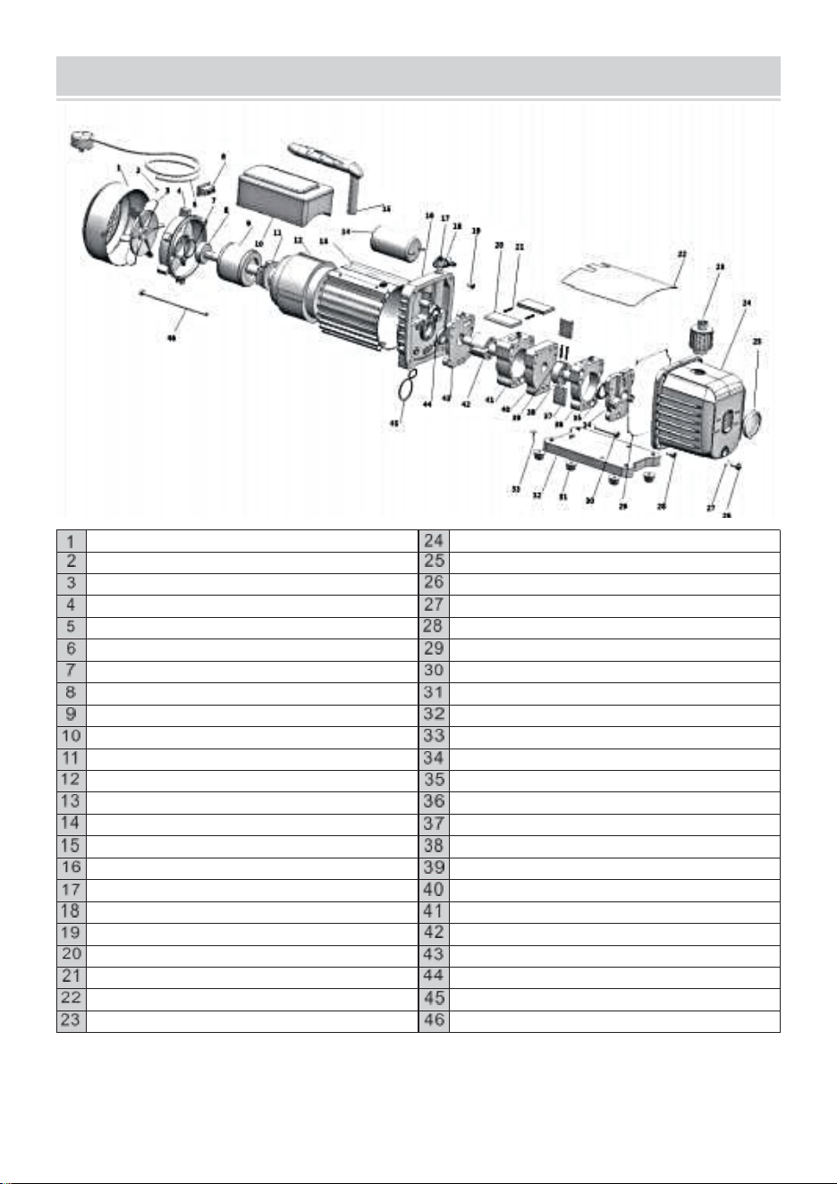
- 16 -
EXPLODED DRAWING
Coperturadelventilatore
Pressofuso alloggiamento in alluminio
Attraverso vite
Vista bicchiere
Fan
Olio drenare
Motore copertina
Olio drenare vite Anello di tenuta
Cavi di alimentazione
Vite
Interruttore di alimentazione
Sigillatura squillo
Rondella
Vite
Cuscinetto
Gomma piede
Motore rotore
Piastra di base
Condensatore scatola
Autofilettante vite
Centrifugo interruttore
Copertura pompa posteriore
Motore statore
Olio foca
Cassa
Indietro - pompa corpo
Capacitore
Indietro - rotativo - a palette
Maniglia
Indietro - pompa rotore
Tre stle
Primavera
Gas berretto
Mezzo recinzione
L' aria ingresso ugello
Anteriore - pompa corpo
Vite
Anteriore - pompa rotore
Davanti rotativo - a palette
Copertina anteriore
Primavera
Olio foca
Capo asse
Lo tipo squillo
Scarico E olio ingresso adatto
Vite
Produttore: WENLING HONGBAOSHI VACUUM EQUIPMENT CO.,LTD
Indirizzo: zona industriale di Yaque, città di Xinhe, città di Wenling, provincia di
Zhejiang


Técnico Certificado de soporte y garantía electrónica
www.vevor.com/support
BOMBA DE VACÍO
GRUPO DE MEDIDORES DE
REFRIGERANTE
MODELO: RS-0.5, RS-1, RS-1.5, RS-2
We continue to be committed to provide you tools with competitive price.
"Save Half", "Half Price" or any other similar expressions used by us only represents an
estimate of savings you might benefit from buying certain tools with us compared to the
major top brands and does not necessarily mean to cover all categories of tools offered by
us. You are kindly reminded to verify carefully when you are placing an order with us if you
are actually saving half in comparison with the top major brands.
- 1 -
MODELO: RS-0.5, RS-1, RS-1.5, RS-2
Have product questions? Need technical support? Please feel free to
contact us:
Technical Support and E-Warranty Certificate
www.vevor.com/support
NEED HELP? CONTACT US!
This is the original instruction, please read all manual instructions
carefully before operating. VEVOR reserves a clear interpretation of our
user manual. The appearance of the product shall be subject to the
product you received. Please forgive us that we won't inform you again if
there are any technology or software updates on our product.
VACUUM PUMP
REFRIGERANT METER GROUP
- 2 -
SAFETY INSTRUCTION
Antesoperanteesteaparato, porfavorleer elinstrucciones manualcon
cuidado y ahorrarestosinstrucciones.Básicoseguridadprecauciones
debería siempreserseguido, incluido elsiguiente:
Advertencia -Parareducir El usuario debe leer atentamente
el riesgo de lesiones. instruccionesmanual
cuidadosamente.ed
EsteEl símbolo, colocado antes de un comentario de seguridad,
indica un tipo de Precaución, advertencia o peligro. Ignorar esta
advertencia puede provocar unaccidente .Para reducir el riesgo
de lesiones, incendio o electrocución, por favorsiempreSiga
la recomendación que se muestra a continuación.
ADVERTENCIA
Familiar Usar Solo.
ADVERTENCIA : Caliente Superficie - A reducir el riesgo de quemaduras , hacer no
tocar .
PRECAUCIÓN : Para reducir el Riesgo de descarga eléctrica, no exponer a la
lluvia. Conservar en interior. PRECAUCIÓN : Para reducir el riesgo de eléctrico
Choque , uso exclusivo en interiores.
ADVERTENCIA : Riesgo de lesión - Hacer no directo aire vapor en el cuerpo .
Utilice z solo des menajes .
ADVERTENCIA : Superficie caliente - para reducir el riesgo de quemaduras, no tocar.
PRECAUCIÓN : Para reducir EL riesgo de choque eléctrico , no no exponer a la
lluvia.
Almacenar en el interior reducir 1 00
PRECAUCIÓN: Para reducir el riesgo de descarga eléctrica, utilice únicamente un
linter - ier .ADVERTENCIA :RIESGO deLesión -No dirija la corriente de aire al
cuerpo.
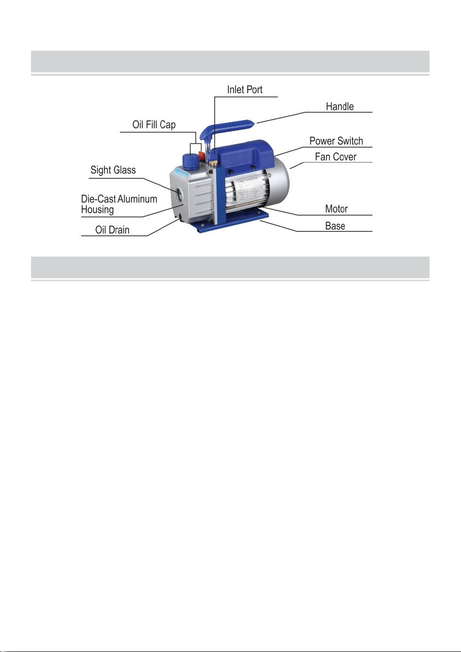
- 3 -
PUMP COMPONENTS
OPERATING MANUAL
1.B antes usando su vacío bomba
En todo cajas , motores son diseñado para operante voltajes más o menos e l
1 0 % de el
normal calificación . Única Voltaje motores son suministrado completamente conectado
y listo a
operar .
( 1 ) Verificar a ser seguro el Voltaje y frecuencia en el salida fósforo el
especificaciones -
ciones en el bomba motor Calcomanía . Comprobar el ENCENDIDO - APAGADO cambiar
a ser seguro él es en el APAGADO
posición antes tú enchufar el bomba en un salida . Quitar y desechar el escape
tapa de el fin de el bomba d e manejar .
( 2 ) El bomba es enviado sin aceite en el depósito . antes a partir de el bomba ,
llenar
él con aceite . Quitar el Escape Adecuado tapa y agregar aceite hasta el aceite justo
muestra en el
abajo de el vista vidrio . El aproximado aceite capacidad de el bomba es
1 8 0 ~ 8 0 0 ml ( referencia el técnico datos ) .
( 3 ) Reemplazar el Escape Adecuado tapa y eliminar el tapa de uno de el
entrada
puertos . Doblar el motor cambiar a ENCENDIDO . Cuando el bomba corre suavemente
, reemplace el tapa
en el entrada puerto . Este puede llevar de dos hasta 3 0 segundos , dependiendo en
el ambiente
temperatura . Después el bomba corre para aproximadamente uno minuto ,
comprobar el vista

- 4 -
vaso para el adecuado aceite nivel . El nivel debería ser incluso con el vista vaso
aceite nivel
línea . Agregar aceite Si es necesario.
Nota : Cuando el bomba es corriendo , el aceite nivel debería ser incluso con el
línea en
el vista vidrio . llenado insuficiente voluntad resultado en pobre vacío Rendimiento .
Sobrellenado poder
resultado en aceite soplo de el escape .

- 5 -
2. A cerrar abajo su bomba después usar
A ayuda prolongar bomba vida y promover fácil Empezando . Seguir estos
procedimientos
para cerrar abajo .
( 1 ) Cerrar el colector válvula entre el bomba y el sistema .
( 2 ) Quitar el manguera de el bomba entrada .
( 3 ) Gorra el entrada puerto a prevenir cualquier contaminación o perder Partículas
de entrando
el puerto .
TO MAINTAIN YOUR HIGH VACUUM PUMP
1. Vacío bomba aceite :
El condición y El tipo de aceite utilizado en cualquier bomba de alto vacío es
extremadamente importante en Determinante el último vacío alcanzable.
Recomendamos el uso de AltoVacío BombaPetróleo .Este aceite tiene Se ha
mezclado específicamente para mantener el máximo viscosidad a temperaturas
normales de funcionamiento y para mejorar el arranque en climas fríos.
2. Petróleo Cambiar Procedimiento
( 1 ) Ser seguro el bomba es calentado arriba .
( 2 ) Quitar el ACEITE DRENAR tapa . drenaje contaminado aceite en a adecuado
recipiente
y disponer de él correctamente . aceite Se puede expulsar el agua de la
bomba abriendo la entrada. y parcialmente bloqueo el escape con a paño
mientras la bomba está funcionando. No opere la bomba durante más
de 20 segundos utilizando este método .
( 3) Cuando el fluir de aceite tiene detenido , inclinado el bomba adelante a
drenar residual aceite .
( 4 ) Reemplazar el ACEITE DRENAR tapa . Quitar el escape adecuado y llenar el
depósito
con nuevo vacío bomba aceite hasta el aceite justo muestra en el abajo de el vista
vidrio . El aproximado aceite capacidad La capacidad de la bomba es de 180-800 ml
(consulte la información técnica) datos ) .
( 5) Asegúrese de que los puertos de entrada estén tapados y luego
encienda la bomba. Déjela funcionar durante uno minuto , entonces controlar el
espacio de nivel de aceite. Si el aceite está por debajo de la mirilla OIL NIVEL
línea , añadir aceite lentamente ( con el bomba correr )hasta que el aceite llegue
al ACEITE NIVEL línea . Reemplazar elescape ajuste, asegurándose de que
la entrada esté
( 6)

- 6 -
a )Sielaceiteesgravemente contaminado con lodo que se forma cuando
se permite el paso del agua arecolectarenelaceite , es posible que tengas que
quitar la tapa del depósito de aceite y limpiarla. él afuera.
b )Otro El método para tratar el petróleo altamente contaminado es forzar el
petróleo a salir. elbombadepósito . Para ello, deje que la bomba funcione hasta que
se caliente. La bomba sigue funcionando, retire la tapa de drenaje de aceite.
Restrinja ligeramente el escape. Esto hará que retroceda . presión elaceite depósitoy
fuerza el aceite de la misma, transportando más contaminación.
Cuando el aceite se acaba a fluir , girar apagado el bomba .
Repita este procedimiento según sea necesario hasta eliminar la contaminación .
ReemplazarelTapar el DRENAJE DE ACEITE y rellenar eldepósito
hasta el nivel adecuado con fresco bomba de aceite

- 7 -
TROUBLESHOOTING GUIDE
Su bomba ha sido utilizada de manera confiable y tiene una larga vida útil. Si algo
sucede , ir incorrecto, la siguiente guía le ayudará a poner la bomba en servicio
nuevamente lo más rápido posible. como posible.
SielDesmontaje Se requiere el uso de la bomba, verifique su garantía. La garantía
puede ser anulado por mal uso o manipulación por parte del cliente, lo que provoca
que la bomba sea inoperable .
1 . Fracaso A Comenzar
Controlar La tensión de línea. La bomba debe arrancar con una tensión de
línea de ±10 % (cargada). a 320 °F. En casos extremos, pueden producirse
cambios entre los devanados de funcionamiento estándar .
2. Petróleo fuga
( 1 ) Ser seguro el aceite es no a residual acumulación de derrame , etc.
( 2 ) Si fuga existe , el módulo cubrir empaquetadora o el eje sello puede necesidad
reemplazando .
Si existe fuga en el área de el aceite drenar enchufe , usted puede necesidad a
volver a sellar el enchufar usando a comercial tubo hilo sellador .
3. Fracaso A Jalar A Bien Vacío
(1) Asegúrese de que el manómetro de vacío y todas las conexiones estén
en buenas condiciones y sin fugas. Puede confirmar si hay fugas controlando el
vacío con un manómetro de termistor. mientras se aplica aceite para bomba de
vacío en conexiones o puntos sospechosos de tener fugas. El vacío mejorará
brevemente mientras el aceite sella la fuga.
(2) Asegúrese de que el aceite de la bomba esté limpio. Una bomba muy
contaminada puede requerir varios lavados de aceite.
(3) Asegúrese de que el aceite esté en el nivel adecuado. Para un
funcionamiento óptimo de la bomba, el aceite debe estar al mismo nivel que la
línea de NIVEL DE ACEITE en el visor cuando la bomba esté funcionando. No
llene en exceso; las temperaturas de funcionamiento harán que el aceite se
expanda, por lo que aparecerá en un nivel más alto que cuando la bomba no
está funcionando. Para verificar el nivel de aceite, encienda la bomba. Bomba
con la entrada tapada. Verifique el nivel de aceite en la mirilla. Agregue aceite si
es necesario.

- 8 -
COMÚN PROBLEMATIROTEO
Falla Descripción
FallaCausa
Solución
Vacío bajo
1. La tapa de entrada de aireen el
puerto de repuesto. lado de el El
puerto de entrada de aire está
suelto.
Apretar el tapa de entrada de
aire
2.El anillo de goma dentro del
aire. entradatapaen El lado
del puerto de repuesto de el aire
entrada El puerto está dañado
Reemplazarel anillo de goma
3.Aceite insuficiente
Repostar a el línea central de el
aceite
indicador
4. El aceite delabomba
está emulsionado . y
inmundo
Reemplazarcon aceite nuevo
5. El orificio de entrada de
aceite de la bomba. es
obstruido o el El suministro de
petróleo es no es suficiente
Limpie el orificio de entrada de
aceite y el filtro . malla
6.Fuga del contenedor de
la tubería Conectado a la
bomba
Controlarel tubo conectado
recipientea Prevenir fugas
7.Selección incorrecta de la
bomba
Compruebe el tamaño de la
bomba . contenedor,
recalcular y seleccionar el
modelo de bomba apropiado
8. La bomba se ha utilizado para
largo , y el el espacio libre es
aumentó pendiente al desgaste
de las piezas
Verifique ,repare o
reemplace el bomba con
unanueva
AceiteFuga
1.Elsello deaceite está dañado.
Reemplazarelsellodeaceite
2.La conexión del tanque de
aceite es
perdero dañado
Apriete los tornillos y
reemplácelos . el Junta
tórica
Inyección de
aceite
1.Demasiadoaceite
Drenar el aceite a el línea de nivel
de aceite
2.ElLa presión de entrada es
demasiado alta para un largo
tiempo
Seleccionarel adecuado
bomba a aumentar la
velocidad debombeo

- 9 -
Arranque difícil
1. La temperatura del aceite es
también bajo
Elaire La entrada está
ventilada, arranca
repetidamente el motor o
CalientaLa bomba de aceite
2.Elmotor o la fuente de
alimentación están falla
Controlar y reparar
3.Extranjero Los objetos
caen en el bomba
Controlar y eliminar
4.Elvoltaje de la fuente de
alimentación es también bajo
Controlar El voltaje de la fuente de
alimentación
Nota:Si elarriba Soluciones hacerno resolversu problema,por favor contacto el más
cercanodistribuidor, o enviarsubomba aa profesional repararcentro, y nosotros
voluntadhacer nuestro mejora atendertú.
Grupo de medidores de refrigerante
INSTRUCCIONES DE USO
Operación Instrucciones
Antes de la conexión, debe comprobar si Los manómetros indican cero. Si no lo
hacen, ajuste el tornillo de ajuste del manómetro para poner el puntero en cero.
Conexión del sistema
En primer lugar, cierre las válvulas de alta presión y de baja presión.
Conecte y asegure el puerto de baja presión - tubo azul - (conector rápido de baja
presión) - lado de baja presión del sistema.
Conecte y asegure el puerto de alta presión - tubo rojo - (conector rápido de alta
presión) - lado de alta presión del sistema.)
Conecte y asegure el puerto de recarga - tubo amarillo - (bomba de vacío).
Sistema de vacío o recuperación
(Precaución: Para un sistema seguro y ahorro de energía, se debe seleccionar la
bomba de vacío o unidad de recuperación adecuada según la presión del sistema)
Después de completar la conexión mencionada anteriormente, primero arranque la
bomba de vacío o la unidad de recuperación.
Abra las válvulas de alta presión y de baja presión juntas, luego (abra los conectores
rápidos de alta y baja presión), el sistema comienza a aspirar o recuperar.
Después de un cierto tiempo (unos 10-30 minutos), verifique
Si el sistema está aspirado. (1f el sistema
No se aspira, se debe verificar si hay alguna fuga en
el sistema y vuelva a vaciarlo después de solucionar el problema de la fuga).
Cierre la válvula de alta presión y la de baja presión juntas.
Por último, cierre la bomba de vacío o la unidad de recuperación.
Mantenga la presión durante 3 a 5 minutos para verificar si hay alguna fuga en el
sistema.

- 10 -
Recarga de refrigerante
Conecte el tubo amarillo con la botella de refrigerante. Abra primero la botella de
refrigerante (posición vertical normal), luego abra la válvula dentro del juego de
manómetros para purgar el aire del tubo amarillo. Invierta la botella de refrigerante y
colóquela bien. Inyecte el refrigerante en la válvula de alta presión hasta la cantidad
especificada (según la especificación de recarga del fabricante). Cierre la válvula.
válvula de alta presión y coloque la botella de refrigerante en su posición vertical
normal.
ConfirmarEfectoRellenar
Primero, inicie la operación del sistema.
Después de un tiempo determinado (aproximadamente 5 a 10 minutos), verifique el
sistema para ver si tanto la presión baja como la alta están en condiciones normales.
Si la presión del sistema es insuficiente, debe
Abra lentamente la válvula de baja presión (no debe abrir la válvula de alta presión
en este momento). Después de agregar una cantidad adecuada de refrigerante
gaseoso (botella de acero en su posición normal hacia arriba), cierre la válvula de
baja presión y verifique
el sistema de nuevo.
Mantenimiento y seguridad
Nunca ejerza demasiada fuerza para abrir o cerrar las válvulas, de lo contrario el
elemento de sellado podría dañarse.
Siga siempre las instrucciones de funcionamiento o utilícelo bajo la guía de un
especialista.
Nunca haga mal uso de la alta y baja presión .
Nunca abra la válvula de alta presión y la válvula de baja presión juntas durante la
operación de recarga.
No utilice nunca un medio de trabajo que no cumpla con la indicación del manómetro.
Nunca deje que la mirilla apunte a ninguna persona para evitar accidentes.
Los manómetros son piezas de desgaste y necesitan calibración periódica. Para una
buena precisión, normalmente deben entregar los manómetros a
la autoridad para la calibración cada 3-6 meses.
Úsalos siempre con cuidado y protégelos de vibraciones o caídas por descuido.
Después del uso, las válvulas deben liberarse y mantenerse
El instrumento se encuentra bien guardado.

- 11 -
TECHNICAL PARAMETER
Código SKU
ACKDZKB235CFM9U8YV3
Modelo
RS-1
Voltaje
220-240 V 50 Hz
Desplazamiento de aire libre
3,5 pies cúbicos por minuto
Vacío definitivo
5PA
Velocidad de rotación
1440
Potencia (HP)
1/4
Capacidad de aceite (ml)
220
Dimensiones (mm)
240*110*220
Peso (Kg)
7
Accesorio
Grupo de medidores de refrigerante
Ámbito de aplicación: R22 R134A R410A R404A
Tres mangueras de 48 pulgadas de largo
1 par de conectores rápidos para aire acondicionado de
coche.
1 par de adaptadores 410A
Código SKU
3CFM1-4HPZKBZJOC1V2
3CFM1-4HPZKBZJ001V3
Modelo
RS-1
Voltaje
220-240 V 50 Hz
Desplazamiento de aire libre
3 pies cúbicos por minuto
Vacío definitivo
5PA
Velocidad de rotación
1440
Potencia (HP)
1/4
Capacidad de aceite (ml)
220
Dimensiones (mm)
240*110*220
Peso (Kg)
6.8
Accesorio
Grupo de medidores de refrigerante
Ámbito de aplicación: R22 R134A R410A
Tres mangueras de 36 pulgadas de largo
1 par de conectores rápidos para aire acondicionado de
coche.
Código SKU
1.8CFM1-4HPZKBZJ1V2
Modelo
RS-0,5
Voltaje
220-240 V 50 Hz
Desplazamiento de aire libre
1,8 pies cúbicos por minuto
Vacío definitivo
5PA
Velocidad de rotación
1440
Potencia (HP)
1/4
Capacidad de aceite (ml)
220
Dimensiones (mm)
240*110*220
Peso (Kg)
6.8
Accesorio
Grupo de medidores de refrigerante
Ámbito de aplicación: R22 R134A R410A

- 12 -
Tres mangueras de 36 pulgadas de largo
1 par de conectores rápidos para aire acondicionado de
coche.

- 13 -
Código SKU
4CFM1/4HPZKB1F001V2
4CFM1/4HPZKB1F001V3
Modelo
RS-1.5
Voltaje
220-240 V 50 Hz
Desplazamiento de aire libre
4 pies cúbicos por minuto
Vacío definitivo
5PA
Velocidad de rotación
1440
Potencia (HP)
1/3
Capacidad de aceite (ml)
225
Dimensiones (mm)
270*110*220
Peso (Kg)
7.6
Accesorio
Grupo de medidores de refrigerante
Ámbito de aplicación: R134A
Tres mangueras de 36 pulgadas de largo
1 par de conectores rápidos para aire acondicionado de
coche.
Código SKU
4CFM1/4HPZKB1F001V1
Modelo
RS-1.5
Voltaje
120 V/60 Hz
Desplazamiento de aire libre
4 pies cúbicos por minuto
Vacío definitivo
5PA
Velocidad de rotación
1720
Potencia (HP)
1/3
Capacidad de aceite (ml)
225
Dimensiones (mm)
270*110*220
Peso (Kg)
7.6
Accesorio
Grupo de medidores de refrigerante
Ámbito de aplicación: R134A
Código SKU
3CFM1-4HPZKBZUMC1V1
Modelo
RS-1
Voltaje
120 V/60 Hz
Desplazamiento de aire libre
3 pies cúbicos por minuto
Vacío definitivo
5PA
Velocidad de rotación
1720
Potencia (HP)
1/4
Capacidad de aceite (ml)
220
Dimensiones (mm)
240*110*220
Peso (Kg)
6.8
Accesorio
Grupo de medidores de refrigerante
Ámbito de aplicación: R22 R134A R410A
Tres mangueras de 36 pulgadas de largo
1 par de conectores rápidos para aire acondicionado de
coche.

- 14 -
Tres mangueras de 36 pulgadas de largo
1 par de conectores rápidos para aire acondicionado de
coche.

- 15 -
Código SKU
4CFM1/3HPZKB4F001V2
Modelo
RS-1.5
Voltaje
220-240 V 50 Hz
Desplazamiento de aire libre
4 pies cúbicos por minuto
Vacío definitivo
5PA
Velocidad de rotación
1440
Potencia (HP)
1/3
Capacidad de aceite (ml)
225
Dimensiones (mm)
270*110*220
Peso (Kg)
7.6
Accesorio
Grupo de medidores de refrigerante
Ámbito de aplicación: R22 R12 R134A R502
Tres mangueras de 36 pulgadas de largo
1 par de conectores rápidos para aire acondicionado de
coche.
1 par de adaptadores 410A
Código SKU
MCKDZK44.8CFM7CNVV1
Modelo
RS-2
Voltaje
120 V/60 Hz
Desplazamiento de aire libre
4,8 pies cúbicos por minuto
Vacío definitivo
5PA
Velocidad de rotación
1720
Potencia (HP)
1/3
Capacidad de aceite (ml)
250
Dimensiones (mm)
290*120*230
Peso (Kg)
9.3
Accesorio
Grupo de medidores de refrigerante
Ámbito de aplicación: R410A R22 R134A R404A
Cuatro mangueras de 60 pulgadas de largo
1 par de conectores rápidos para aire acondicionado de
coche.
1 par de adaptadores 410A
Código SKU
MCKDZK43.6CFM6DQYV1
Modelo
RS-1
Voltaje
120 V/60 Hz
Desplazamiento de aire libre
3,6 pies cúbicos por minuto
Vacío definitivo
5PA
Velocidad de rotación
1720
Potencia (HP)
1/4
Capacidad de aceite (ml)
220
Dimensiones (mm)
240*110*220
Peso (Kg)
8
Accesorio
Grupo de medidores de refrigerante
Ámbito de aplicación: R410A R22 R134A R404A
Cuatro mangueras de 60 pulgadas de largo
1 par de conectores rápidos para aire acondicionado de

- 16 -
coche.
1 par de adaptadores 410A
1 abridor de botellas
1 juego de herramientas
Código SKU
4.8CFM1/3HPZKB3F1V2
4.8CFM1/3HPZKB3F1V3
Modelo
RS-2
Voltaje
220-240 V 50 Hz
Desplazamiento de aire libre
4,8 pies cúbicos por minuto
Vacío definitivo
5PA
Velocidad de rotación
1440
Potencia (HP)
1/3
Capacidad de aceite (ml)
250
Dimensiones (mm)
290*120*230
Peso (Kg)
8.6
Accesorio
Grupo de medidores de refrigerante
Ámbito de aplicación: R22 R134A R410A
Tres mangueras de 36 pulgadas de largo
1 par de conectores rápidos para aire acondicionado de
coche.
Código SKU
4.8CFM1/3HPZKB3F1V1
Modelo
RS-2
Voltaje
120 V/60 Hz
Desplazamiento de aire libre
4,8 pies cúbicos por minuto
Vacío definitivo
5PA
Velocidad de rotación
1720
Potencia (HP)
1/3
Capacidad de aceite (ml)
250
Dimensiones (mm)
290*120*230
Peso (Kg)
8.6
Accesorio
Grupo de medidores de refrigerante
Ámbito de aplicación: R22 R134A R410A
Tres mangueras de 36 pulgadas de largo
1 par de conectores rápidos para aire acondicionado de
coche.
Código SKU
MCKDZK44.8CFM7CNVV2
Modelo
RS-2
Voltaje
220-240 V 50 Hz
Desplazamiento de aire libre
4,8 pies cúbicos por minuto
Vacío definitivo
5PA
Velocidad de rotación
1440
Potencia (HP)
1/3
Capacidad de aceite (ml)
250
Dimensiones (mm)
290*120*230
Peso (Kg)
8.6
Accesorio
Grupo de medidores de refrigerante

- 17 -
Ámbito de aplicación: R410A R22 R134A R404A
Cuatro mangueras de 60 pulgadas de largo
1 par de conectores rápidos para aire acondicionado de
coche.
1 par de adaptadores 410A
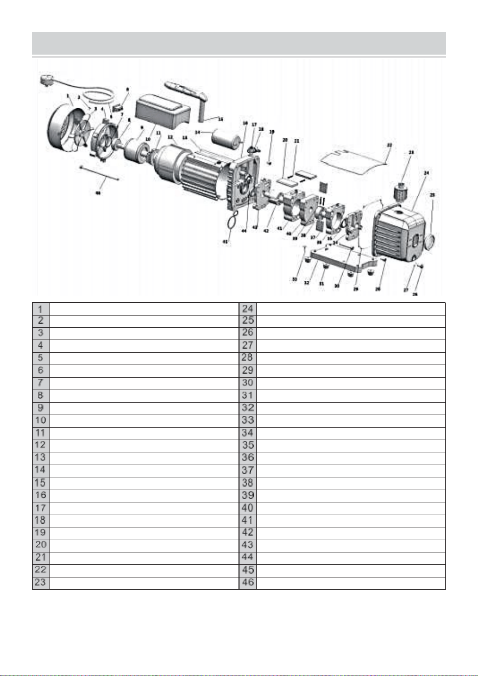
- 18 -
EXPLODED DRAWING
Tapadelventilador
Fundición a presión carcasa de aluminio
Cruz tornillo
Vista vaso
Admirador
Aceite drenar
Motor cubrir
Aceite drenar tornillo Ju n t a tórica
Cables de alimentación
Tornillo
Interruptor de encendido
Caza de focas anillo
Lavadora
Tornillo
Cojinete
Goma pie
Motor rotor
Placa base
Condensador caja
Autorroscante tornillo
Centrífugo cambiar
Tapa delabomba trasera
Motor Estator
Aceite sello
Carcasa
Atrás - bomba cuerpo
Condensador
Atrás - rotatorio - paletas
Manejar
Atrás - bomba rotor
Tres estilos
Primavera
Gas tapa
Medio cerca
El aire entrada boquilla
Delantero - bomba cuerpo
Tornillo
Delantero - bomba rotor
Frente rotativo - paletas
Portada
Primavera
Aceite sello
Tapa p junta
Oh tipo anillo
Escape y aceite entrada adecuado
Tornillo
EQUIPO DE VACÍO WENLING HONGBAOSHI Compañía Limitada
Dirección: Zona industrial de Yaque, ciudad de Xinhe, ciudad de Wenling,
provincia de Zhejiang


Techniczny Wsparcie i certyfikat e-gwarancji
www.vevor.com/support
POMPA PRÓŻNIOWA
GRUPA MIERNIKÓW CZYNNIKA
CHŁODNICZEGO
MODELE: RS-0,5, RS-1, RS-1,5, RS-2
We continue to be committed to provide you tools with competitive price.
"Save Half", "Half Price" or any other similar expressions used by us only represents an
estimate of savings you might benefit from buying certain tools with us compared to the
major top brands and does not necessarily mean to cover all categories of tools offered by
us. You are kindly reminded to verify carefully when you are placing an order with us if you
are actually saving half in comparison with the top major brands.

- 1 -
MODELE: RS-0,5, RS-1, RS-1,5, RS-2
Have product questions? Need technical support? Please feel free to
contact us:
Technical Support and E-Warranty Certificate
www.vevor.com/support
NEED HELP? CONTACT US!
This is the original instruction, please read all manual instructions
carefully before operating. VEVOR reserves a clear interpretation of our
user manual. The appearance of the product shall be subject to the
product you received. Please forgive us that we won't inform you again if
there are any technology or software updates on our product.
VACUUM PUMP
REFRIGERANT METER GROUP
- 2 -
SAFETY INSTRUCTION
ZanimoperacyjnyTenurządzenie, Proszę Czytać ten instrukcje podręcznik
ostrożnie I ratować teinstrukcje.Podstawowybezpieczeństwośrodki
ostrożnościpowinienzawszeByć śledzony, w tym tennastępny:
Ostrzeżenie -Dozmniejszyć ryzyko obrażeń, użytkownik
musi zapoznać się z instrukcją instrukcje instrukcja obsługi
dokładnie.ed
Tensymbol umieszczony przed komentarzem dotyczącym
bezpieczeństwa wskazuje na rodzaj środek ostrożności,
ostrzeżenie lub niebezpieczeństwo. Zignorowanie tego
ostrzeżenia może prowadzić do jakiśwypadek .Aby zmniejszyć
ryzyko obrażeń, pożaru lub porażenia prądem, Proszę
zawszepostępuj zgodnie z poniższymi zaleceniami.
UWAGA
Gospodarstwo domowe Używać Tylko.
OSTRZEŻENIE : Gorący Powierzchnia - Do zmniejszyć ten ryzyko z oparzenia , robić
nie dotykać .
UWAGA : Do zmniejszyć ten Ryzyko porażenia prądem, nie wystawiać na
działanie deszczu. Przechowywać w pomieszczeniu. UWAGA : Do zmniejszyć ten
ryzyko z elektryczny wstrząs , stosować wyłącznie wewnątrz pomieszczeń.
OSTRZEŻENIE : Ryzyko z uraz - Zrób nie bezpośredni powietrze para Na ten ciało .
Wykorzystaj z odosobnienie des menażki .
OSTRZEŻENIE : Powierzchnia gorąco - za zmniejszyć ryzyko poparzenia, nie dotykać.
UWAGA : Dla zmniejszyć TO ryzyko z zaszokować elektryczny , nie nie wystawiać
na działanie deszczu.
Sklep w pomieszczeniu 1 00
UWAGA: Aby zmniejszyć ryzyko porażenia prądem, należy używać wyłącznie linte
r - tj .OSTRZEŻENIE :RYZYKO z obrażenia -Nie kieruj przeciągu na ciało.

- 3 -
PUMP COMPONENTS
OPERATING MANUAL
1.B wcześniej używając twój próżnia pompa
W Wszystko obudowy , silniki Czy zaprojektowany Do operacyjny napięcia plus Lub
minus 1 0 % z ten
normalna ocena . Pojedynczy woltaż silniki Czy Dostarczono w pełni połączony I
gotowy Do
operować .
( 1 ) Sprawdź Do Być Jasne ten woltaż I częstotliwość Na ten wylot mecz ten
specyfikacja -
cje NA ten pompa silnik naklejka . Sprawdź ten WŁ. - WYŁ. przełącznik Do Być Jasne
To Jest W ten WYŁĄCZONY
pozycja zanim Ty wtyczka ten pompa do jakiś wylot . Usuń I wyrzucać ten
wydechowy
czapka z ten koniec z ten pompa uchwyt .
( 2 ) Ten pompa Jest wysłany bez olej W ten zbiornik . Przed startowy ten pompa ,
wypełnić
To z olej . Usuń ten Wydechowy Dopasowywanie czapka I dodać olej dopóki ten olej
Tylko widać W ten
spód z ten wzrok szkło . przybliżony olej pojemność z ten pompa Jest
1 8 0 ~ 8 0 0 ml ( odniesienie ten techniczny dane ) .
( 3 ) Zastąp ten Wydechowy Dopasowywanie czapka I usunąć ten czapka z jeden
z ten wlot
porty . Zakręt ten silnik przełącznik Do WŁ . Kiedy ten pompa biegnie płynnie ,
wymienić ten czapka
NA ten wlot port . To móc Brać z dwa do 3 0 sekund , w zależności NA ten otoczenia
temperatura . Po ten pompa biegnie Do około jeden minuta , sprawdź ten wzrok
szkło Do ten właściwy olej poziom . poziom powinien Być nawet z ten wzrok szkło
olej poziom

- 4 -
linia . Dodaj olej w razie potrzeby.
Uwaga : Kiedy ten pompa Jest bieganie , olej poziom powinien Być nawet z
ten linia NA
ten wzrok szkło . Podpełnienie będzie wynik W słaby próżnia wydajność .
Przepełnienie Móc
wynik W olej dmuchanie z ten wydech .

- 5 -
2. Do zamknąć w dół twój pompa Po używać
Do pomoc wydłużać pompa życie I promować łatwy rozpoczynając . Obserwuj te
procedury
Do zamknąć w dół .
( 1 ) Zamknij ten wieloraki zawór między ten pompa I ten systemu .
( 2 ) Usuń ten wąż gumowy z ten pompa wlot .
( 3 ) Czapka ten wlot port Do zapobiegać każdy zanieczyszczenie Lub luźny
cząsteczki z wstępowanie
ten porto .
TO MAINTAIN YOUR HIGH VACUUM PUMP
1. Odkurzacz pompaolej l :
Ten stan I rodzaj oleju stosowanego w dowolnej pompie próżniowej jest
niezwykle ważny W określający ten ostateczny osiągalna próżnia. Zalecamy
użycie Wysoki Próżnia Pompa Olej . To olej ma zostały specjalnie zmieszane, aby
zachować maksymalną lepkość w normalnych temperaturach roboczych i
poprawa rozruchu w zimnych warunkach.
2. Olej Zmiana Procedura
( 1 ) Być Jasne ten pompa Jest rozgrzany w górę .
( 2 ) Usuń ten OLEJ ODPŁYW czapka . Odpływ zanieczyszczony olej do A
odpowiedni pojemnik
I dysponować z To właściwie . Olej można wycisnąć z pompy poprzez
otwarcie wlotu I częściowo bloking ten wydechowy z A płótno podczas pracy
pompy. Nie uruchamiaj pompy na dłużej niż 20 sekund stosując tę
metodę .
( 3) Kiedy ten przepływ z olej ma zatrzymany , przechylony ten pompa do przodu
Do odpływ pozostały olej .
( 4 ) Zamień ten OLEJ ODPŁYW czapka . Usuń ten wydechowy dopasowywanie I
wypełnić ten zbiornik
z nowy próżnia pompa olej dopóki ten olej Tylko widać Na ten spód z ten wzrok
szkło . przybliżony olej pojemność pompki 180-800ml (patrz dane techniczne)
dane ) .
( 5) Upewnij się, że otwory wlotowe są zaślepione, a następnie włącz pompę.
Pozwól jej pracować przez jeden minuta , potem sprawdzać przestrzeń poziomu
oleju. Jeśli olej jest poniżej szklanego wskaźnika OLEJU POZIOM linia , dodaj
olej powoli ( z ten pompa działanie )aż olej osiągnie OLEJ POZIOM linia .
Zamień ten wydechowy dopasowanie, upewniając się, że wlot jest
( 6)
a )Jeśli ten olej Jest źle zanieczyszczone osadem, który powstaje, gdy woda
jest dopuszczona Dozbierać Wtenolej , może być konieczne zdjęcie pokrywy
zbiornika oleju i wytarcie To na zewnątrz.

- 6 -
b )Inny metodą postępowania z silnie zanieczyszczoną ropą jest wyciśnięcie z niej
oleju tenpompazbiornik .Aby to zrobić, pozwól pompie pracować, aż się nagrzeje.
Podczas gdy pompa nadal pracuje, zdejmij korek spustowy oleju. Nieznacznie
ogranicz wydech. To spowoduje powrót - ciśnienie tenolej zbiornikI siła ten z niego
olej, przenosząc więcej zanieczyszczeń.
Kiedy olej się zepsuje Do płynąć , obracać się wyłączony ten pompa .
Powtarzaj tę procedurę tak często, aż zanieczyszczenie zostanie usunięte .
Zastępowaćten Odkręć korek spustowy oleju i napełnij zbiornik do
właściwego poziomu świeży pompa oleju.

- 7 -
TROUBLESHOOTING GUIDE
Twoja pompa jest niezawodna i ma długą żywotność. Jeśli coś powinno Iść źle,
poniższy przewodnik pomoże Ci jak najszybciej przywrócić pompę do użytku Jak
możliwy.
Jeśli ten demontaż Jeśli wymagana jest pompa, sprawdź gwarancję. Gwarancja
móc Być unieważniony przez niewłaściwego użycia lub ingerencji klienta, skutkującej
uszkodzeniem pompy nieoperacyjny .
1. Niepowodzenie Do Start
Sprawdzać napięcie sieciowe. Pompa musi się uruchomić przy ±10%
napięcia sieciowego (obciążona) przy 320F. W skrajnych przypadkach może
wystąpić przełączanie pomiędzy standardowymi uzwojeniami roboczymi .
2. Olej przeciek
( 1 ) Być Jasne ten olej Jest nie A pozostały akumulacja z rozlanie itp .
( 2 ) Jeśli przeciek istnieje , moduł okładka uszczelka Lub ten wał foka móc
potrzebować zastąpienie .
Jeżeli występuje wyciek w ten obszar z ten olej odpływ podłącz , ty móc
potrzebować Do ponownie zapieczętować ten wtyczka używając A handlowy
rura nitka uszczelniacz .
3. Niepowodzenie Do Ciągnąć A Dobry Próżnia
(1) Upewnij się, że wskaźnik podciśnienia i wszystkie połączenia są w
dobrym stanie i nie ma w nich wycieków. Wyciek można potwierdzić,
monitorując podciśnienie za pomocą wskaźnika termistorowego. podczas
nakładania oleju do pompy próżniowej na połączenia lub podejrzewane punkty
wycieku. Podciśnienie poprawi się na krótko, podczas gdy olej uszczelni wyciek.
(2) Upewnij się, że olej pompy jest czysty. Mocno zanieczyszczona pompa
może wymagać kilku płukanek olejem.
(3) Upewnij się, że olej jest na właściwym poziomie. Aby zapewnić
maksymalną wydajność pompy, olej musi być równy z linią POZIOMU OLEJU
na szkle kontrolnym, gdy pompa pracuje. Nie przepełniaj — temperatury
robocze powodują rozszerzanie się oleju, więc będzie on wyświetlany na
wyższym poziomie niż wtedy, gdy pompa nie pracuje. Aby sprawdzić poziom
oleju, uruchom pompę z zatkanym wlotem. Sprawdź poziom oleju w okienku
kontrolnym. W razie potrzeby dolej oleju.

- 8 -
WSPÓLNY KŁOPOTYSTRZELANIE
Awaria Opis
WadaPrzyczyna
Rozwiązanie
Niskapróżnia
1. Zaślepka wlotupowietrza na
porcie zapasowym strona z ten
otwór wlotowy powietrza jest
luźny.
Dokręcać ten zaślepka wlotu
powietrza
2.Gumowy pierścień wewnątrz
powietrza wlotczapka NA
zapasowa burta portu ten
powietrze wlot port jest
uszkodzony
Zastępować tenpierścień
gumowy
3.Niedobór oleju
Zatankować Do ten linia środkowa
z ten olej
miernik
4. Olej pompy jest
emulgowany I nieczysty
Zastępowaćz nowyolej
5.Otwórwlotowyolejupompy
Jest zablokowanyLub ten
Dostawa ropy naftowej jest
niewystarczający
Wyczyść otwór wlotowy oleju i
filtr oczko
6.Wyciek pojemnika rury
podłączony do pompy
Sprawdzaćtenrura
połączona pojemnik Do
zapobiegać wyciekom
7.Niewłaściwydobór pompy
Sprawdź rozmiar pompy d
kontener, przelicz i wybierz t
odpowiedni model pompy
8. Pompa była używana do
długi i ten prześwit jest
zwiększony należny do zużycia
części
Sprawdź ,napraw lub
wymień pompuj z nowym
na e
Olej Przeciek
1.Uszczelka olejowajest
uszkodzona
Zastępowaćtenuszczelkaolejowa
2.Podłączenie zbiornika oleju jest
luźnylub uszkodzone
Dokręćśruby i wymień ten
Pierścień uszczelniający
Wtrysk oleju
1.Zbytdużo oleju
Odpływten olejDo ten linia
poziomu oleju
2.Tenciśnienie wlotowe jest
zbyt wysokie Do długi czas
Wybieraćten odpowiedni
pompować do zwiększ
prędkość pompowania
Temperatura oleju Jest zbyt Niski
Tenpowietrze wlot jest
wentylowany,
wielokrotnie uruchamia silnik

- 9 -
Trudny start
lub ogrzewa pompa oleju
2.Silnik lub zasilacz jest
uszkodzony
Sprawdzać i naprawa
3.Zagraniczny obiekty
wpadają do pompa
Sprawdzać i wyeliminować
4.Napięcie zasilania wynosi
zbyt Niski
Sprawdzać napięcie zasilania
Notatka:Jeśli tenpowyżej rozwiązania Donie rozwiązywać twój problem, Proszę kontakt
tennajbliższy kupiec, Lub wysłaćtwójpompaDo A profesjonalnynaprawa centrum,I My
będzieDo naszto, co najlepszeDopodawać Ty.
Grupa mierników czynnika chłodniczego
INSTRUKCJA UŻYTKOWANIA
Działanie Instrukcje
Przed podłączeniem należy sprawdzić, czy manometry wskazują zero. Jeśli tak nie
jest, należy wyregulować śrubę nastawczą manometru, aby ustawić wskazówkę na
zero.
Połączenie systemowe
Przede wszystkim zamknij oba zawory: wysokiego i niskiego ciśnienia.
Podłącz i zabezpiecz port niskiego ciśnienia - niebieską rurkę - (szybkozłącze
niskiego ciśnienia) - stronę niskiego ciśnienia systemu.
Podłącz i zabezpiecz port wysokiego ciśnienia - czerwoną rurkę - (szybkozłącze
wysokiego ciśnienia) - po stronie wysokiego ciśnienia systemu.)
Podłącz i zabezpiecz port napełniania - żółtą rurkę - (pompę próżniową).
System próżniowy lub odzysk
(Uwaga: Aby zapewnić bezpieczeństwo systemu i oszczędność energii, należy
wybrać odpowiednią pompę próżniową lub jednostkę odzyskującą w zależności od
ciśnienia w systemie)
Po wykonaniu powyższych połączeń należy w pierwszej kolejności uruchomić
pompę próżniową lub jednostkę odzyskującą.
Otwórz jednocześnie zawór wysokiego ciśnienia i zawór niskiego ciśnienia, a
następnie (otwórz oba szybkozłącza wysokiego i niskiego ciśnienia) system
rozpocznie odkurzanie lub odzyskiwanie.
Po upływie określonego czasu (około 10-30 minut) sprawdź
jeśli układ jest odkurzony. (1f układ
nie jest odkurzony, należy sprawdzić, czy nie ma wycieku
(należy oczyścić układ i ponownie go odkurzyć po usunięciu problemu z
nieszczelnością.)
Zamknij jednocześnie zawór wysokiego ciśnienia i zawór niskiego ciśnienia.

- 10 -
Na koniec należy zamknąć pompę próżniową lub jednostkę odzyskującą.
Utrzymuj ciśnienie przez 3–5 minut, aby sprawdzić, czy w układzie nie ma wycieków.
Uzupełnij czynnik chłodniczy
Podłącz żółtą rurkę do butli z czynnikiem chłodniczym. Najpierw otwórz butlę z
czynnikiem chłodniczym (normalna pozycja pionowa), a następnie otwórz zawór
wewnątrz zestawu wskaźników, aby usunąć powietrze z żółtej rurki. Odwróć butlę z
czynnikiem chłodniczym i umieść ją prawidłowo. Wstrzyknij czynnik chłodniczy do
zaworu wysokiego ciśnienia do określonej ilości (zgodnie ze specyfikacją producenta
dotyczącą napełniania). Zamknij
zawór wysokiego ciśnienia i ustaw butlę z czynnikiem chłodniczym w normalnej
pozycji pionowej.
Potwierdź efekt ponownego napełnienia
Najpierw należy uruchomić system.
Po pewnym czasie (około 5-10 minut) sprawdź, czy system jest w normalnym stanie
zarówno podciśnienia, jak i podciśnienia. Jeśli ciśnienie w systemie jest
niewystarczające, należy
powoli otwórz zawór niskiego ciśnienia (nie otwieraj zaworu wysokiego ciśnienia w
tym momencie). Po uzupełnieniu odpowiedniej ilości gazowego czynnika
chłodniczego (stalowa butla w normalnej pozycji pionowej) zamknij zawór niskiego
ciśnienia i sprawdź
system ponownie.
Konserwacja i bezpieczeństwo
Nigdy nie należy używać nadmiernej siły przy otwieraniu lub zamykaniu zaworów,
gdyż może to spowodować uszkodzenie elementu uszczelniającego.
Zawsze postępuj zgodnie z instrukcją obsługi lub korzystaj z urządzenia pod
nadzorem specjalisty.
Nigdy nie nadużywaj wysokiego i niskiego ciśnienia .
Nigdy nie otwieraj jednocześnie zaworu wysokiego ciśnienia i zaworu niskiego
ciśnienia podczas napełniania.
Nigdy nie należy używać medium roboczego niezgodnie ze wskazaniem na zestawie
manometrów.
Aby uniknąć wypadku, nigdy nie kieruj celownika na jakąkolwiek osobę.
Manometry są częściami eksploatacyjnymi i wymagają okresowej kalibracji. Aby
uzyskać dobrą dokładność, zazwyczaj należy dostarczać manometry do
upoważnienie do kalibracji co 3-6 miesięcy.

- 11 -
Zawsze używaj ich ostrożnie i chroń je przed wibracjami lub przypadkowym
upadkiem.
Po użyciu należy zwolnić zawory i zachować je
instrument dobrze przechowywany.

- 12 -
TECHNICAL PARAMETER
Numer katalogowy
ACKDZKB235CFM9U8YV3
Model
RS-1
Woltaż
220-240 V 50 Hz
Wolne przemieszczanie
powietrza
3,5 stóp sześciennych na minutę
Najlepszy odkurzacz
5PA
Prędkość obrotowa
1440
Moc (KM)
1/4
Pojemność oleju (ml)
220
Wymiary (mm)
240*110*220
Waga (kg)
7
Akcesorium
Grupa mierników czynnika chłodniczego
Zakres zastosowania: R22 R134A R410A R404A
Trzy węże o długości 48 cali
1 para szybkozłączek do klimatyzacji samochodowej
1 para adapterów 410A
Numer katalogowy
3CFM1-4HPZKBZJOC1V2
3CFM1-4HPZKBZJ001V3
Model
RS-1
Woltaż
220-240 V 50 Hz
Wolne przemieszczanie
powietrza
3 stopy sześcienne na minutę
Najlepszy odkurzacz
5PA
Prędkość obrotowa
1440
Moc (KM)
1/4
Pojemność oleju (ml)
220
Wymiary (mm)
240*110*220
Waga (kg)
6.8
Akcesorium
Grupa mierników czynnika chłodniczego
Zakres zastosowania: R22 R134A R410A
Trzy węże o długości 36 cali
1 para szybkozłączek do klimatyzacji samochodowej
Numer katalogowy
1,8CFM1-4HPZKBZJ1V2
Model
RS-0,5
Woltaż
220-240 V 50 Hz
Wolne przemieszczanie
powietrza
1,8 stóp sześciennych na minutę
Najlepszy odkurzacz
5PA
Prędkość obrotowa
1440
Moc (KM)
1/4
Pojemność oleju (ml)
220
Wymiary (mm)
240*110*220
Waga (kg)
6.8
Akcesorium
Grupa mierników czynnika chłodniczego

- 13 -
Zakres zastosowania: R22 R134A R410A
Trzy węże o długości 36 cali
1 para szybkozłączek do klimatyzacji samochodowej

- 14 -
Numer katalogowy
4CFM1/4HPZKB1F001V2
4CFM1/4HPZKB1F001V3
Model
RS-1.5
Woltaż
220-240 V 50 Hz
Wolne przemieszczanie
powietrza
4 stopy sześcienne na minutę
Najlepszy odkurzacz
5PA
Prędkość obrotowa
1440
Moc (KM)
1/3
Pojemność oleju (ml)
225
Wymiary (mm)
270*110*220
Waga (kg)
7.6
Akcesorium
Grupa mierników czynnika chłodniczego
Zakres zastosowania: R134A
Trzy węże o długości 36 cali
1 para szybkozłączek do klimatyzacji samochodowej
Numer katalogowy
4CFM1/4HPZKB1F001V1
Model
RS-1.5
Woltaż
120V/60Hz
Wolne przemieszczanie
powietrza
4 stopy sześcienne na minutę
Najlepszy odkurzacz
5PA
Prędkość obrotowa
1720
Moc (KM)
1/3
Pojemność oleju (ml)
225
Wymiary (mm)
270*110*220
Waga (kg)
7.6
Akcesorium
Grupa mierników czynnika chłodniczego
Zakres zastosowania: R134A
Numer katalogowy
3CFM1-4HPZKBZUMC1V1
Model
RS-1
Woltaż
120V/60Hz
Wolne przemieszczanie
powietrza
3 stopy sześcienne na minutę
Najlepszy odkurzacz
5PA
Prędkość obrotowa
1720
Moc (KM)
1/4
Pojemność oleju (ml)
220
Wymiary (mm)
240*110*220
Waga (kg)
6.8
Akcesorium
Grupa mierników czynnika chłodniczego
Zakres zastosowania: R22 R134A R410A
Trzy węże o długości 36 cali
1 para szybkozłączek do klimatyzacji samochodowej

- 15 -
Trzy węże o długości 36 cali
1 para szybkozłączek do klimatyzacji samochodowej

- 16 -
Numer katalogowy
4CFM1/3HPZKB4F001V2
Model
RS-1.5
Woltaż
220-240 V 50 Hz
Wolne przemieszczanie
powietrza
4 stopy sześcienne na minutę
Najlepszy odkurzacz
5PA
Prędkość obrotowa
1440
Moc (KM)
1/3
Pojemność oleju (ml)
225
Wymiary (mm)
270*110*220
Waga (kg)
7.6
Akcesorium
Grupa mierników czynnika chłodniczego
Zakres stosowania: R22 R12 R134A R502
Trzy węże o długości 36 cali
1 para szybkozłączek do klimatyzacji samochodowej
1 para adapterów 410A
Numer katalogowy
MCKDZK44.8CFM7CNVV1
Model
RS-2
Woltaż
120V/60Hz
Wolne przemieszczanie
powietrza
4,8 stóp sześciennych na minutę
Najlepszy odkurzacz
5PA
Prędkość obrotowa
1720
Moc (KM)
1/3
Pojemność oleju (ml)
250
Wymiary (mm)
290*120*230
Waga (kg)
9.3
Akcesorium
Grupa mierników czynnika chłodniczego
Zakres zastosowania: R410A R22 R134A R404A
Cztery węże o długości 60 cali
1 para szybkozłączek do klimatyzacji samochodowej
1 para adapterów 410A
Numer katalogowy
MCKDZK43.6CFM6DQYV1
Model
RS-1
Woltaż
120V/60Hz
Wolne przemieszczanie
powietrza
3,6 stóp sześciennych na minutę
Najlepszy odkurzacz
5PA
Prędkość obrotowa
1720
Moc (KM)
1/4
Pojemność oleju (ml)
220
Wymiary (mm)
240*110*220
Waga (kg)
8
Akcesorium
Grupa mierników czynnika chłodniczego
Zakres zastosowania: R410A R22 R134A R404A
Cztery węże o długości 60 cali
1 para szybkozłączek do klimatyzacji samochodowej

- 17 -
1 para adapterów 410A
1 otwieracz do butelek
1 zestaw narzędzi
Numer katalogowy
4,8CFM1/3HPZKB3F1V2
4,8CFM1/3HPZKB3F1V3
Model
RS-2
Woltaż
220-240 V 50 Hz
Wolne przemieszczanie
powietrza
4,8 stóp sześciennych na minutę
Najlepszy odkurzacz
5PA
Prędkość obrotowa
1440
Moc (KM)
1/3
Pojemność oleju (ml)
250
Wymiary (mm)
290*120*230
Waga (kg)
8.6
Akcesorium
Grupa mierników czynnika chłodniczego
Zakres zastosowania: R22 R134A R410A
Trzy węże o długości 36 cali
1 para szybkozłączek do klimatyzacji samochodowej
Numer katalogowy
4,8CFM1/3HPZKB3F1V1
Model
RS-2
Woltaż
120V/60Hz
Wolne przemieszczanie
powietrza
4,8 stóp sześciennych na minutę
Najlepszy odkurzacz
5PA
Prędkość obrotowa
1720
Moc (KM)
1/3
Pojemność oleju (ml)
250
Wymiary (mm)
290*120*230
Waga (kg)
8.6
Akcesorium
Grupa mierników czynnika chłodniczego
Zakres zastosowania: R22 R134A R410A
Trzy węże o długości 36 cali
1 para szybkozłączek do klimatyzacji samochodowej
Numer katalogowy
MCKDZK44.8CFM7CNVV2
Model
RS-2
Woltaż
220-240 V 50 Hz
Wolne przemieszczanie
powietrza
4,8 stóp sześciennych na minutę
Najlepszy odkurzacz
5PA
Prędkość obrotowa
1440
Moc (KM)
1/3
Pojemność oleju (ml)
250
Wymiary (mm)
290*120*230
Waga (kg)
8.6
Akcesorium
Grupa mierników czynnika chłodniczego

- 18 -
Zakres zastosowania: R410A R22 R134A R404A
Cztery węże o długości 60 cali
1 para szybkozłączek do klimatyzacji samochodowej
1 para adapterów 410A
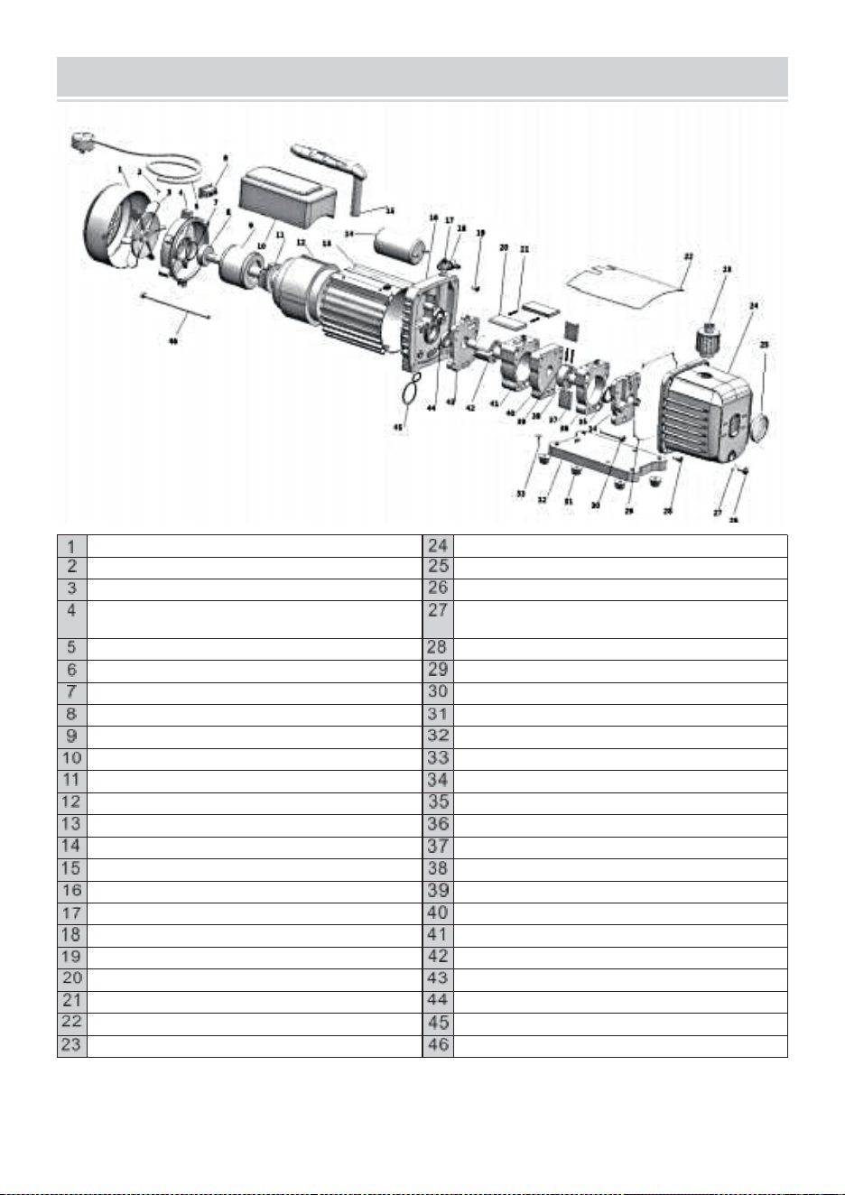
- 19 -
EXPLODED DRAWING
Osłonawentylatora
Odlew kostkowy obudowa aluminiowa
Przechodzić śruba
Wzrok szkło
Wentylator
Olej odpływ
Silnik okładka
Olej odpływ śruba Pierścień
uszczelniający
Przewody zasilające
Śruba
Wyłącznik zasilania
Opieczętowanie pierścień
Pralka
Śruba
Łożysko
Guma stopa
Silnik wirnik
Płyta bazowa
Kondensator skrzynka
Samogwintujące śruba
Odśrodkowy przełącznik
Pokrywa pompy tylnej
Silnik stojan
O i l foka
Obudowa
Tył - pompa ciało
Pacytor kondensatora
Tył - obrotowy - łopatkowy
Uchwyt
Tył - pompa wirnik
Trzy kroki
Wiosna
Gaz czapka
Środek ogrodzenie
powietrze wlot dysza
Przód - pompa ciało
Śruba
Przód - pompa wirnik
Przód obrotowy - łopatkowy
Okładka przednia
Wiosna
O i l foka
Ka p tablica
O typ pierścień
Wydech I olej wlot dopasowywanie
Śruba
Producent: WENLING HONGBAOSHI VACUUM EQUIPMENT Spółka z
ograniczoną odpowiedzialnością

- 20 -
Adres: Strefa przemysłowa Yaque, miasto Xinhe, miasto Wenling, prowincja
Zhejiang


Technisch Ondersteuning en E-garantiecertificaat
www.vevor.com/support
VACUÜMPOMP
KOELMIDDELMETERGROEP
MODEL: RS-0.5, RS-1, RS-1.5, RS-2
We continue to be committed to provide you tools with competitive price.
"Save Half", "Half Price" or any other similar expressions used by us only represents an
estimate of savings you might benefit from buying certain tools with us compared to the
major top brands and does not necessarily mean to cover all categories of tools offered by
us. You are kindly reminded to verify carefully when you are placing an order with us if you
are actually saving half in comparison with the top major brands.

- 1 -
MODEL: RS-0.5, RS-1, RS-1.5, RS-2
Have product questions? Need technical support? Please feel free to
contact us:
Technical Support and E-Warranty Certificate
www.vevor.com/support
NEED HELP? CONTACT US!
This is the original instruction, please read all manual instructions
carefully before operating. VEVOR reserves a clear interpretation of our
user manual. The appearance of the product shall be subject to the
product you received. Please forgive us that we won't inform you again if
there are any technology or software updates on our product.
VACUUM PUMP
REFRIGERANT METER GROUP

- 2 -
SAFETY INSTRUCTION
Vooroperationeelditapparaat,Alsjeblieftlezende instructieshandmatig
voorzichtig En redden dezeinstructies.Basisveiligheid
voorzorgsmaatregelenzoumoetenaltijdzijngevolgd, inbegrepen de volgend g :
Waarschuwing -Aanverminderenhet risico op letsel, moet
de gebruiker de instructieshandleiding zorgvuldig
doorlezen
Ditsymbool, geplaatst voor een veiligheidsopmerking, geeft een
soort voorzorgsmaatregel, waarschuwing of gevaar. Het
negeren van deze waarschuwing kan leiden tot eenongeluk .
Om het risico op letsel, brand of elektrocutie te verminderen,
AlsjeblieftaltijdVolg de onderstaande aanbeveling.
WAARSCHUWING
Huishouden Gebruik Alleen.
WAARSCHUWING : Heet Oppervlakte - Naar verminderen de risico van
brandwonden , doen niet aanraken .
LET OP : Om verminderen de Gevaar voor elektrische schokken. Niet blootstellen
aan regen. Binnenshuis bewaren. LET OP : Om verminderen de risico van
elektrisch schok , alleen binnenshuis gebruiken.
WAARSCHUWING : Risico van letsel - Doen niet rechtstreeks lucht stoom bij de
lichaam .
Gebruik z seulement des menages .
WAARSCHUWING : Oppervlak heet - voor verminder het risico op brandwonden, raak
het niet aan. LET OP : Voor verminderen DE risico van schok elektrisch , niet niet
blootstellen aan regen.
Winkel binnenshuis veroorzaken 1 00
LET OP: Om het risico op een elektrische schok te verminderen, mag u alleen een
lint gebruiken . ier .WAARSCHUWING :RISICOvan letsel -Richt geen tocht op het
lichaam.

- 3 -
PUMP COMPONENTS
OPERATING MANUAL
1.B vóór gebruiken jouw vacuüm pomp
In alle gevallen , motoren Zijn ontworpen voor operationeel spanningen plus of min
1 0 % van de
normaal beoordeling . Enkel spanning motoren Zijn geleverd volledig aangesloten En
klaar naar
bedienen .
( 1 ) Controleren naar zijn Zeker de spanning En frequentie bij de uitlaat
overeenkomst de specificeren -
ties op de pomp motor sticker . Controleer de AAN - UIT schakelaar naar zijn Zeker Het
is in de UIT
positie voor Jij plug de pomp naar binnen een stopcontact . Verwijderen En
weggooien de uitlaat
pet van de einde van de pomp ' s hendel .
( 2 ) De pomp is verzonden zonder olie in de reservoir . Voor beginnend de pomp ,
vullen
Het met olie . Verwijderen de Uitlaat Passend pet En toevoegen olie tot de olie zojuist
toont in de
onderkant van de zicht glas . De bij benadering olie capaciteit van de pomp is
1 8 0 ~ 8 0 0 ml ( referentie de technisch gegevens ) .
( 3 ) Vervangen de Uitlaat Passend pet En verwijderen de pet van een van de
inlaat
havens . Draai de motor schakelaar naar AAN . Wanneer de pomp loopt soepel ,
vervangen de pet
op de inlaat haven . Deze kunnen nemen van twee tot 3 0 seconden , afhankelijk van
op de omgeving
temperatuur . Na de pomp loopt voor ongeveer een minuut , controleren de zicht

- 4 -
glas voor de juist olie niveau . De niveau zou moeten zijn zelfs met de zicht glas olie
niveau
lijn . Toevoegen olie indien nodig.
Let op : Wanneer de pomp is rennen , de olie niveau zou moeten zijn zelfs met
de lijn op
de zicht glas . Ondervulling zullen resultaat in arm vacuüm prestatie . Overvulling
kan
resultaat in olie blazen van de uitlaat .

- 5 -
2. Aan dicht omlaag jouw pomp na gebruik
Naar hulp verlengen pomp leven En bevorderen eenvoudig beginnend . Volgen deze
werkwijze
voor dicht omlaag .
( 1 ) Sluiten de verdeelstuk ventiel tussen de pomp En de systeem .
( 2 ) Verwijderen de slang van de pomp inlaat .
( 3 ) Dop de inlaat haven naar voorkomen elk besmetting of loszittend deeltjes van
binnenkomen
de haven .
TO MAINTAIN YOUR HIGH VACUUM PUMP
1.Vacuüm pomp olie l :
De voorwaarde En Het type olie dat in een hoogvacuümpomp wordt gebruikt, is
extreem belangrijk in bepalend de ultiem haalbaar vacuüm. Wij raden het
gebruik van aan Hoog Vacuüm Pomp Olie .Dit olie heeft speciaal gemengd om een
maximale viscositeit bij normale bedrijfstemperaturen en om starten bij koud weer
te verbeteren.
2. Olie Wijziging Procedure
( 1 ) Wees Zeker de pomp is opgewarmd omhoog .
( 2 ) Verwijderen de OLIE DROOGLEGGEN dop . Afvoer verontreinigd olie naar
binnen A geschikt houder
En weggooien van Het correct . Olie kan uit de pomp worden gedwongen door
de inlaat te openen En gedeeltelijk blokkeren de uitlaat met A lap terwijl de
pomp draait. Laat de pomp niet langer dan 20 seconden draaien met
deze methode .
( 3) Wanneer de stroom van olie heeft gestopt , kantelen de pomp vooruit naar
droogleggen resterend olie .
( 4 ) Vervangen de OLIE DROOGLEGGEN dop . Verwijderen de uitlaat passend
En vullen de reservoir
met nieuw vacuüm pomp olie tot de olie zojuist toont bij de onderkant van de zicht
glas . De bij benadering olie capaciteit van de pomp is 180-800ml (raadpleeg de
technische gegevens) gegevens ) .
( 5)Zorg ervoor dat de inlaatpoorten zijn afgedekt en zet de pomp aan. Laat
deze een paar minuten draaien. een minuut ,dan rekening de oliepeilruimte. Als
de olie onder het kijkglas OIL staat NIVEAU lijn , toevoegen olie langzaam ( m
et de pomp rennen )totdat de olie de OLIE bereikt NIVEAU lijn .Vervangen de
uitlaat montage, waarbij ervoor gezorgd wordt dat de inlaat
( 6)
a )Als deolie is slecht verontreinigd met slib dat ontstaat als er water wordt
toegelaten naar verzamelen indeolie , moet u mogelijk het deksel van het
oliereservoir verwijderen en afvegen Het uit.

- 6 -
b )Een andere De manier om met zwaar vervuilde olie om te gaan, is door de olie
eruit te persen. de pomp stuwmeer . Om dit te doen, laat de pomp draaien totdat
deze is opgewarmd. Terwijl de pomp draait nog, verwijder de olie - aftapdop.
Beperk de uitlaat enigszins. Dit zal terug - drukdeolie reservoirEnkrachtde olie, wat
nog meer verontreiniging met zich meebrengt.
Als de olie slinkt naar stromen , draaien uit de pomp .
Herhaal deze procedure indien nodig totdat de verontreiniging is verwijderd .
VervangendeOLIEAFVOERdop en vul het reservoir tot het juiste niveau
met vers olie pompen.

- 7 -
TROUBLESHOOTING GUIDE
Uw pomp is voor betrouwbaar gebruik en heeft een lange levensduur. Als er iets
zou moeten gaan Als het fout is, kunt u met de volgende handleiding de pomp zo
snel mogelijk weer in bedrijf krijgen. als mogelijk.
Als de demontage van de pomp is vereist, controleer dan uw garantie.De garantie
kunnen zijn ongeldig verklaard door verkeerd gebruik of manipulatie door de klant,
waardoor de pomp wordt beschadigd niet te opereren .
1. Mislukking Naar Begin
Rekening de netspanning. De pomp moet starten bij ±10% netspanning
(belast) bij 320F. In extreme gevallen kan er worden geschakeld tussen de
standaardwikkelingen .
2. Olie lekkage
( 1 ) Wees Zeker de olie is niet A resterend ophoping van morsen , enz .
( 2 ) Als lekkage bestaat , de module omslag pakking of de schacht zegel kunnen
behoefte vervangen .
Als er sprake is van lekkage in de gebied van de olie droogleggen stekker , jij
kunnen behoefte naar opnieuw verzegelen de plug gebruik makend van A
commercieel pijp draad afdichtmiddel .
3. Mislukking Naar Trekken A Goed Vacuüm
(1)Zorg ervoor dat de vacuümmeter en alle aansluitingen in goede staat zijn
en niet lekken. U kunt lekkage bevestigen door het vacuüm te controleren met
een thermistormeter. tijdens het aanbrengen van vacuümpompolie bij
aansluitingen of vermoedelijke lekpunten. Het vacuüm zal kortstondig verbeteren
terwijl de olie het lek dicht.
(2)Zorg ervoor dat de pompolie schoon is. Een ernstig vervuilde pomp kan
meerdere oliespoelingen nodig hebben.
(3)Zorg ervoor dat de olie op het juiste niveau staat. Voor een maximale
werking van de pomp moet de olie gelijk zijn met de OLIEPEIL-lijn op het
kijkglas wanneer de pomp draait. Vul niet te veel bij ---- de bedrijfstemperaturen
zorgen ervoor dat de olie uitzet, waardoor het op een hoger niveau verschijnt
dan wanneer de pomp niet draait. Om het oliepeil te controleren, start u de pomp
met de inlaat afgedekt. Controleer het oliepeil in het kijkglas. Voeg indien nodig
olie toe.

- 8 -
GEWOON PROBLEEMSCHIETEN
Mislukking
Beschrijving
SchuldOorzaak
Oplossing
Laagvacuüm
1. De luchtinlaatdop op de
reservepoort kantvan de
Luchtinlaatpoort zit los.
Vastdraaien de luchtinlaatdop
2.De rubberen ring in de lucht
inlaat pet op de reserve
bakboordzijde van de lucht inlaat
poort is beschadigd
Vervangen derubberen ring
3.Onvoldoende olie
Bijtanken naar de middenlijn van
de olie
graadmeter
4. De pompolie wordt
geëmulgeerd En onrein
Vervangenmet nieuweolie
5.Het olie-inlaatgat van de
pomp is geblokkeerd of de
olievoorziening is
onvoldoende
Maak het olie-inlaatgat en het
filter schoon gaas
6.Lekkagevande
pijpcontainer aangesloten
op de pomp
Rekeningde aangesloten
pijp houder naar lekkage
voorkomen
7.Onjuiste pompselectie
Controleer de grootte van de
pomp container, opnieuw
berekenen en selecteren het
geschikte pompmodel
8. De pomp is gebruikt om o
lang , en de klaring is
toegenomen vanwege aan de
slijtage van onderdelen
Controleer ,repareerof
vervang de pomp met een
nieuwe ope
OlieLekkage
1.Deoliekeerringisbeschadigd
Vervangende oliekeerring
2.De aansluiting van de olietank is
loszittendof beschadigd
Draaideschroeven vast en
vervang ze de O - ring
Olie -injectie
1.Teveelolie
Droogleggen de olie naar de
oliepeillijn
2.Deinlaatdruk is te hoog
voor een lange tijd
Selecteer degepast pompen
naar verhoog de
pompsnelheid
Moeilijk starten
De olietemperatuur is te laag
De lucht inlaat is
geventileerd, start
herhaaldelijk de motor of
verwarmtde pomp olie

- 9 -
2.De motor of voedingis
defect
Rekening en reparatie
3.Buitenlands voorwerpen
vallen in de pomp
Rekening enelimineren
4.Devoedingsspanning is te
laag
Rekeningde voedingsspanning
Opmerking:Als debovenoplossingenDoennietoplossen jouwprobleem,Alsjeblieft
contactdedichtstbijzijndehandelaar,of versturenjouwpomp naar A professioneel
reparatiecentrum, En Wij zullenDoenons bestnaardienenJij.
Koelmiddelmetergroep
GEBRUIKSAANWIJZING
Bediening Instructies
Voordat u verbinding maakt, moet u controleren of De drukmeters geven nul aan. Als
dat niet het geval is, moet u de instelschroef op de drukmeter zo ver draaien dat de
wijzer op nul staat.
Systeemverbinding
Sluit eerst zowel de hogedrukklep als de lagedrukklep.
Sluit de lagedrukpoort - blauwe buis - (snelkoppeling voor lagedruk) - aan de
lagedrukzijde van het systeem aan en zet deze vast.
Sluit de hogedrukpoort (rode buis) (snelkoppeling voor hoge druk) aan en bevestig
deze aan de hogedrukzijde van het systeem.)
Sluit de bijvulpoort aan en zet deze vast - gele slang - (vacuümpomp).
Vacuümsysteem of herstel
(Let op: voor een veilig systeem en energiebesparing moet de juiste vacuümpomp of
vacuümunit worden geselecteerd op basis van de systeemdruk)
Nadat de bovengenoemde verbinding tot stand is gebracht, start u eerst de
vacuümpomp of de opvangunit.
Open zowel de hogedrukklep als de lagedrukklep tegelijk en open vervolgens de
snelkoppelingen voor zowel de hogedruk- als de lagedrukklep. Het systeem begint
met vacuümzuigen of herstellen.
Controleer na een bepaalde tijd (ongeveer 10-30 minuten)
als het systeem wordt gestofzuigd. (1f het systeem
wordt niet gestofzuigd, moet worden gecontroleerd of er lekkage is
(Het systeem schoonmaken en opnieuw stofzuigen nadat het lekprobleem is
verholpen.)
Sluit zowel de hogedrukklep als de lagedrukklep gelijktijdig.
Sluit tot slot de vacuümpomp of de opvangunit.
Houd de druk 3 tot 5 minuten aan om te controleren of er lekkage in het systeem is.
Koelmiddel bijvullen

- 10 -
Sluit de gele buis aan op de koelmiddelfles. Open eerst de koelmiddelfles (normale
rechtopstaande positie) en open vervolgens de klep in de meterset om lucht uit de
gele buis te verwijderen. Draai de koelmiddelfles om en plaats deze goed. Injecteer
het koelmiddel in de hogedrukklep tot de opgegeven hoeveelheid (volgens de
navulspecificatie van de fabrikant). Sluit de
hogedrukventiel en plaats de koelmiddelfles in de normale rechtopstaande positie.
BevestigenRefillEffect
Start eerst de systeembewerking.
Controleer na een bepaalde tijd (ongeveer 5-10 minuten) of zowel de lage druk als de
hoge druk in normale staat zijn. Als de systeemdruk onvoldoende is, moet het
Open langzaam de lagedrukklep (de hogedrukklep mag op dit moment niet worden
geopend). Nadat een juiste hoeveelheid gasvormig koelmiddel (stalen fles in de
normale rechtopstaande positie) is aangevuld, sluit u de lagedrukklep en controleert u
het systeem opnieuw.
Onderhoud en Veiligheid
Oefen nooit te veel kracht uit bij het openen of sluiten van de kleppen, anders kan het
afdichtingselement beschadigd raken.
Volg altijd de gebruiksaanwijzing of bedien het apparaat onder begeleiding van een
specialist.
Maak nooit verkeerd gebruik van hoge druk en lage druk .
Open nooit tegelijkertijd de hogedrukklep en de lagedrukklep tijdens het bijvullen.
Gebruik nooit een werkmedium dat niet overeenkomt met de aanduiding op de
meterset.
Richt het kijkglas nooit op een persoon, om ongelukken te voorkomen.
De drukmeters zijn slijtageonderdelen en ze moeten periodiek worden gekalibreerd.
Voor een goede nauwkeurigheid moet het normaal gesproken de meters leveren aan
de instantie die elke 3-6 maanden een kalibratie uitvoert.
Gebruik ze altijd voorzichtig en bescherm ze tegen trillingen of onvoorzichtig vallen.
Na gebruik moeten de kleppen worden losgelaten en vastgehouden
het instrument goed opgeborgen.

- 11 -
TECHNICAL PARAMETER
SKU
ACKDZKB235CFM9U8YV3
Model
RS-1
Spanning
220-240V 50Hz
Gratis luchtverplaatsing
3,5CFM
Ultieme vacuüm
5PA
Rotatiesnelheid
1440
Vermogen (PK)
1/4
Oliecapaciteit (ml)
220
Afmeting (mm)
240*110*220
Gewicht (kg)
7
Accessoire
Koelmiddelmetergroep
Toepassingsgebied: R22 R134A R410A R404A
Drie 48 inch lange slangen
1 paar auto-airco snelkoppelingen
1 paar 410A-adapters
SKU
3CFM1-4HPZKBZJOC1V2
3CFM1-4HPZKBZJ001V3
Model
RS-1
Spanning
220-240V 50Hz
Gratis luchtverplaatsing
3CFM
Ultieme vacuüm
5PA
Rotatiesnelheid
1440
Vermogen (PK)
1/4
Oliecapaciteit (ml)
220
Afmeting (mm)
240*110*220
Gewicht (kg)
6.8
Accessoire
Koelmiddelmetergroep
Toepassingsgebied: R22 R134A R410A
Drie slangen van 36 inch lang
1 paar auto-airco snelkoppelingen
SKU
1.8CFM1-4HPZKBZJ1V2
Model
RS-0,5
Spanning
220-240V 50Hz
Gratis luchtverplaatsing
1,8CFM
Ultieme vacuüm
5PA
Rotatiesnelheid
1440
Vermogen (PK)
1/4
Oliecapaciteit (ml)
220
Afmeting (mm)
240*110*220
Gewicht (kg)
6.8
Accessoire
Koelmiddelmetergroep
Toepassingsgebied: R22 R134A R410A
Drie slangen van 36 inch lang
1 paar auto-airco snelkoppelingen

- 12 -
SKU
4CFM1/4HPZKB1F001V2
4CFM1/4HPZKB1F001V3
Model
RS-1.5
Spanning
220-240V 50Hz
Gratis luchtverplaatsing
4CFM
Ultieme vacuüm
5PA
Rotatiesnelheid
1440
Vermogen (PK)
1/3
Oliecapaciteit (ml)
225
Afmeting (mm)
270*110*220
Gewicht (kg)
7.6
Accessoire
Koelmiddelmetergroep
Toepassingsgebied: R134A
Drie slangen van 36 inch lang
1 paar auto-airco snelkoppelingen
SKU
4CFM1/4HPZKB1F001V1
Model
RS-1.5
Spanning
120V/60Hz
Gratis luchtverplaatsing
4CFM
Ultieme vacuüm
5PA
Rotatiesnelheid
1720
Vermogen (PK)
1/3
Oliecapaciteit (ml)
225
Afmeting (mm)
270*110*220
Gewicht (kg)
7.6
Accessoire
Koelmiddelmetergroep
Toepassingsgebied: R134A
Drie slangen van 36 inch lang
1 paar auto-airco snelkoppelingen
SKU
3CFM1-4HPZKBZUMC1V1
Model
RS-1
Spanning
120V/60Hz
Gratis luchtverplaatsing
3CFM
Ultieme vacuüm
5PA
Rotatiesnelheid
1720
Vermogen (PK)
1/4
Oliecapaciteit (ml)
220
Afmeting (mm)
240*110*220
Gewicht (kg)
6.8
Accessoire
Koelmiddelmetergroep
Toepassingsgebied: R22 R134A R410A
Drie slangen van 36 inch lang
1 paar auto-airco snelkoppelingen

- 13 -
SKU
4CFM1/3HPZKB4F001V2
Model
RS-1.5
Spanning
220-240V 50Hz
Gratis luchtverplaatsing
4CFM
Ultieme vacuüm
5PA
Rotatiesnelheid
1440
Vermogen (PK)
1/3
Oliecapaciteit (ml)
225
Afmeting (mm)
270*110*220
Gewicht (kg)
7.6
Accessoire
Koelmiddelmetergroep
Toepassingsgebied: R22 R12 R134A R502
Drie slangen van 36 inch lang
1 paar auto-airco snelkoppelingen
1 paar 410A-adapters
SKU
MCKDZK44.8CFM7CNVV1
Model
RS-2
Spanning
120V/60Hz
Gratis luchtverplaatsing
4,8CFM
Ultieme vacuüm
5PA
Rotatiesnelheid
1720
Vermogen (PK)
1/3
Oliecapaciteit (ml)
250
Afmeting (mm)
290*120*230
Gewicht (kg)
9.3
Accessoire
Koelmiddelmetergroep
Toepassingsgebied: R410A R22 R134A R404A
Vier slangen van 60 inch lang
1 paar auto-airco snelkoppelingen
1 paar 410A-adapters
SKU
MCKDZK43.6CFM6DQYV1
Model
RS-1
Spanning
120V/60Hz
Gratis luchtverplaatsing
3,6CFM
Ultieme vacuüm
5PA
Rotatiesnelheid
1720
Vermogen (PK)
1/4
Oliecapaciteit (ml)
220
Afmeting (mm)
240*110*220
Gewicht (kg)
8
Accessoire
Koelmiddelmetergroep
Toepassingsgebied: R410A R22 R134A R404A
Vier slangen van 60 inch lang
1 paar auto-airco snelkoppelingen
1 paar 410A-adapters
1 flesopener

- 14 -
1 gereedschapsset
SKU
4.8CFM1/3HPZKB3F1V2
4.8CFM1/3HPZKB3F1V3
Model
RS-2
Spanning
220-240V 50Hz
Gratis luchtverplaatsing
4,8CFM
Ultieme vacuüm
5PA
Rotatiesnelheid
1440
Vermogen (PK)
1/3
Oliecapaciteit (ml)
250
Afmeting (mm)
290*120*230
Gewicht (kg)
8.6
Accessoire
Koelmiddelmetergroep
Toepassingsgebied: R22 R134A R410A
Drie slangen van 36 inch lang
1 paar auto-airco snelkoppelingen
SKU
4.8CFM1/3HPZKB3F1V1
Model
RS-2
Spanning
120V/60Hz
Gratis luchtverplaatsing
4,8CFM
Ultieme vacuüm
5PA
Rotatiesnelheid
1720
Vermogen (PK)
1/3
Oliecapaciteit (ml)
250
Afmeting (mm)
290*120*230
Gewicht (kg)
8.6
Accessoire
Koelmiddelmetergroep
Toepassingsgebied: R22 R134A R410A
Drie slangen van 36 inch lang
1 paar auto-airco snelkoppelingen
SKU
MCKDZK44.8CFM7CNVV2
Model
RS-2
Spanning
220-240V 50Hz
Gratis luchtverplaatsing
4,8CFM
Ultieme vacuüm
5PA
Rotatiesnelheid
1440
Vermogen (PK)
1/3
Oliecapaciteit (ml)
250
Afmeting (mm)
290*120*230
Gewicht (kg)
8.6
Accessoire
Koelmiddelmetergroep
Toepassingsgebied: R410A R22 R134A R404A
Vier slangen van 60 inch lang
1 paar auto-airco snelkoppelingen
1 paar 410A-adapters
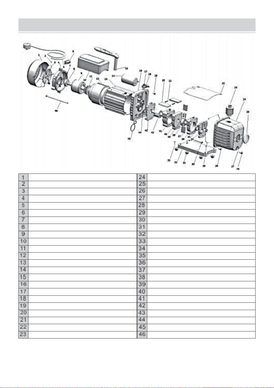
- 15 -
EXPLODED DRAWING
Ventilatorkap
Gegoten aluminium behuizing
Kruis schroef
Zicht glas
Fan
Olie droogleggen
Motor omslag
Olie droogleggen schroef O - ring
Voedingskabels
Schroef
Stroomschakelaar
Afdichten ring
Wasmachine
Schroef
Handelswijze
Rubber voet
Motor rotor
Bodemplaat
Condensator doos
Zelftappend schroef
Centrifugaal schakelaar
Terugpompdeksel
Motor stator
O ik l zegel
Behuizing
Terug - pomp lichaam
Ca fopspeen
Achterkant - roterend - schoepen
Hendel
Terug - pomp rotor
Tre -stijl
Lente
Gas pet
Midden le schutting
De lucht inlaat mondstuk
Voorzijde - pomp lichaam
Schroef
Voorzijde - pomp rotor
Voorkant roterend - schoepen
Voorkant
Lente
O ik l zegel
Kaap bord
O type ring
Uitgerust huis En olie inlaat passend
Schroef
Fabrikant: WENLING HONGBAOSHI VACUUM EQUIPMENT CO.,LTD
Adres: Yaque Industrial Zone, Xinhe Town, Wenling City, provincie Zhejiang


Teknisk Support och e-garanticertifikat
www.vevor.com/support
VAKUUMPUMP
KÖLDMEDIEMÄTARGRUPP
MODELL: RS-0.5, RS-1, RS-1.5, RS-2
We continue to be committed to provide you tools with competitive price.
"Save Half", "Half Price" or any other similar expressions used by us only represents an
estimate of savings you might benefit from buying certain tools with us compared to the
major top brands and does not necessarily mean to cover all categories of tools offered by
us. You are kindly reminded to verify carefully when you are placing an order with us if you
are actually saving half in comparison with the top major brands.

- 1 -
MODELL: RS-0.5, RS-1, RS-1.5, RS-2
Have product questions? Need technical support? Please feel free to
contact us:
Technical Support and E-Warranty Certificate
www.vevor.com/support
NEED HELP? CONTACT US!
This is the original instruction, please read all manual instructions
carefully before operating. VEVOR reserves a clear interpretation of our
user manual. The appearance of the product shall be subject to the
product you received. Please forgive us that we won't inform you again if
there are any technology or software updates on our product.
VACUUM PUMP
REFRIGERANT METER GROUP

- 2 -
SAFETY INSTRUCTION
Förefungerardettaapparat,behaga läsa deinstruktionermanuell försiktigt en
ndsparadessainstruktioner.Grundläggandesäkerhetförsiktighetsåtgärder
skallalltidvaraföljde, inklusivede följande g :
Varning -Tillminska risken för skada måste användaren
läsa instruktionermanual noggrant.ed
Dettasymbol, placerad före en säkerhetskommentar, indikerar ett
slags försiktighetsåtgärd, varning eller fara. Att ignorera denna
varning kan leda till att enolycka .För att minska risken för
skada, brand eller elstöt, behagaalltidfölj
rekommendationen nedan.
VARNING
Hushåll Använda Endast.
VARNING : Varm Yta - Till minska de risk av brännskador , gör inte beröring .
VARNING : Till minska de risk för elektriska stötar, utsätt inte för regn. Förvara
inomhus. VARNING : Till minska de risk av elektrisk chock , använd endast
inomhus.
VARNING : Risk av skada - Gör inte direkt luft ånga på de kropp .
Använd z seulement des menages .
VARNING : Yta het - För minska risken för brännskador, rör inte. VARNING : För
minska DE risk av chock elektrisk , inte inte utsättas för regn.
Lagra inomhusducera 100
VARNING: För att minska risken för elektriska stötar, använd endast en linte r - ieur
.VARNING :RISKavskada -Rikta inte drag mot kroppen.

- 3 -
PUMP COMPONENTS
OPERATING MANUAL
1.Före använder din vakuum pump
I alla fall , motorer är utformad för fungerar spänningar plus eller minus 1 0 % av
de
normal betyg . Enda spänning motorer är levereras fullt ansluten och redo till
fungera .
( 1 ) Kontrollera till vara säker de spänning och frekvens på de utlopp match de
specifica -
tioner på de pump motor dekal . Kontrollera de PÅ - AV växla till vara säker det är i
de AV
placera före du plugg de pump till en uttag . Ta bort och kassera de uttömma
lock från de avsluta av de pumpar handtag .
( 2 ) Den pump är skickas utan olja i de reservoar . Före startande de pump ,
fylla
det med olja . Ta bort de Uttömma Montering lock och tillägga olja tills de olja precis
visar i de
botten av de syn glas . De ungefärlig olja kapacitet av de pump är
1 8 0 ~ 8 0 0 ml ( referens de teknisk data ) .
( 3 ) Byt ut de Uttömma Montering lock och ta bort de lock från en av de inlopp
hamnar . Sväng de motor växla till PÅ . När de pump springer smidigt , byt ut de
lock
på de inlopp hamn . Detta maj ta från två till 3 0 sekunder , beroende på de
omgivande
temperatur . Efter de pump springer för cirka en minut , kolla de syn
glas för de rätt olja nivå . De nivå skall vara även med de syn glas olja nivå
linje . Tillägga olja om så behövs.
Obs : När de pump är löpning , den olja nivå skall vara även med de linje på

- 4 -
de syn glas . Underfyllning vilja resultat i dålig vakuum prestanda . Överfyllning
burk
resultat i olja blåsning från de avgaser .

- 5 -
2. Till stänga ner din pump efter använda
Till hjälp förlänga pump liv och främja lätt startar . Följa dessa förfaranden
för stänga ner .
( 1 ) Stäng de grenrör ventil mellan de pump och de system .
( 2 ) Ta bort de slang från de pump inlopp .
( 3 ) Kap de inlopp hamn till förhindra några förorening eller lösa partiklar från går
in
de hamn .
TO MAINTAIN YOUR HIGH VACUUM PUMP
1. Vakuum pumpoj l :
De skick och typ av olja som används i alla högvakuumpumpar är extremt
viktig i bestämmande de slutlig uppnåeligt vakuum. Vi rekommenderar användning
av Hög VakuumPump Olja . Detta olja har har blandats specifikt för att bibehålla
maximalt viskositet vid normala driftstemperaturer och för att förbättra start vid kall
väderlek.
2. Olja Ändra Förfarande
( 1 ) Var säker de pump är uppvärmd upp .
( 2 ) Ta bort de OLJA DRÄNERA keps . Dränera förorenat olja till a lämplig
behållare
och kassera av det ordentligt . Olja kan tvingas bort från pumpen genom att
öppna inloppet och delvis blockering de uttömma med a trasa medan
pumpen är igång. Använd inte pumpen i mer än 20 sekunder med denna
metod .
( 3) När de flöde av olja har stannade , luta de pump fram till dränera resterande
olja .
( 4 ) Byt ut de OLJA DRÄNERA keps . Ta bort de uttömma montering och fylla de
reservoar
med ny vakuum pump olja tills de olja precis visar på de botten av de syn
glas . De ungefärlig olja kapacitet av pumpen är 180-800ml (referera till den tekniska
d ata ).
( 5) Se till att inloppsportarna är täckta och sätt sedan på pumpen. Låt den
springa en minut alltså kontrollera oljenivåutrymmet. Om oljan är under
synglaset OIL NIVÅ linje , lägg till olja långsamt ( med de pump spring )tills
oljan når OLJA NIVÅ linje . Ersätta de uttömma passning, se till att inloppet är
( 6)
a )Omdeolja är dåligt förorenat med slam som bildas när vatten tillåts till
samlai deolja kan du behöva ta bort oljebehållarens lock och torka av det
ut.
b )En annan metod för att hantera kraftigt förorenad olja är att tvinga oljan från
de pump reservoar . För att göra detta, låt pumpen gå tills den är uppvärmd. Medan

- 6 -
pumpen fortfarande går, ta bort oljeavtappningslocket. Begränsa avgaserna något.
Detta kommer att göra - tryck de oljareservoar och tvingade olja från den, som bär mer
förorening.
När oljan c lättar till flyta , vända av de pump .
Upprepa denna procedur vid behov tills kontamineringen har tagits bort .
ErsättadeOLJA TÖMMA lock och fyll på behållaren till rätt nivå med
färsk pumpolja.

- 7 -
TROUBLESHOOTING GUIDE
Din pump har varit för pålitlig användning och har en lång livslängd. Om något
skulle d gå fel, kommer följande guide att hjälpa dig att få pumpen i drift igen så
snabbt som möjlig.
Omde demontering av pumpen krävs, kontrollera din garanti. Garantin maj vara
ogiltigförklarad av missbruk eller kundmanipulation, vilket resulterar i att pumpen blir
inoperabel .
1 . Fel Till Start
Kontrollera linjespänningen. Pumpen måste starta vid ±10 % nätspänning
(belastad) vid 320F. I extrema fall kan växling mellan standarddriftlindningarna
ske .
2. O il läckage
( 1 ) Var säker de olja är inte a resterande ackumulation från spill osv .
( 2 ) Om läckage existerar , den modul täcka packning eller de axel täta maj behov
byter ut .
Om läckage finns i de område av de olja dränera plugga , du maj behov till
återförslutning de plugg använda ng a kommersiell rör tråd förseglare .
3. Misslyckande Till Dra A Bra Vakuum
(1) Se till att vakuummätaren och alla anslutningar är i gott skick och
läckagefria. Du kan bekräfta läckage genom att övervaka vakuumet med en
termistormätare medan du applicerar vakuumpumpolja vid anslutningar eller
misstänkta läckagepunkter. Vakuumet förbättras en kort stund medan oljan tätar
läckan.
(2) Se till att pumpoljan är ren. En kraftigt förorenad pump kan kräva flera
oljespolningar.
(3) Se till att oljan är på rätt nivå. För maximal pumpdrift måste oljan vara
jämn med OLJENIVÅlinjen på synglaset när pumpen är igång. Överfyll inte----
drifttemperaturer kommer att få oljan att expandera, så den kommer att synas på
en högre nivå än när pumpen inte är igång. För att kontrollera oljenivån, starta
pump med inloppslocket. Kontrollera oljenivån i synglaset. Tillsätt olja om det
behövs.

- 8 -
VANLIGT PROBLEMSKYTTE
misslyckande
Beskrivning
FelOrsaka
Lösning
Lågtvakuumm
1. Luftinloppslocket på
reservporten sida av de
luftinloppsporten är lös.
Spänna de luftintagslock
2. Gummiringen inne i luften
inlopp lockpå reservsidan av
babord deluft inlopp porten är
skadad
Ersättadegummiring
3. Otillräcklig olja
Tanka till de mittlinje av de olja
g auge
4. Pumpoljan är emulgerad
d och oren
Ersättamed ny olja
5. Pumpens oljeinloppshål är
blockerad ellerde
oljeförsörjning är jag är
otillräcklig
Rengör oljeinloppshålet och
filtret r maska
6.Läckage av rörbehållare
ansluten till pumpen
Kontrolleradeanslutet rör
behållaretill förhindra
läckage
7. Felaktigt pumpval
Kontrollera storleken på
pumpen d behållare, beräkna
om och välj t lämplig
pumpmodell
8. Pumpen har använts för att o
lång , och de godkännande är
ökade förfallen till slitage på delar
Kontrollera ,reparera eller
byt ut pump med en ny på
e
OljaLäckage
1. Oljetätningen är skadad
Ersättadeoljetätning
2.Oljetankanslutningen är
lösaellerskadad
Dra åt skruvarnaoch byt ute
de O - ring
Oljeinsprutning n
1.Förmycketolja
Dränerade oljatill de
oljenivålinjen
2.Den inloppstrycket är för
högt för länge
Väljade lämplig pumpa till öka
pumphastighetend
Hård start
1. Oljetemperaturen är för låg
De luft inloppet är ventilerat,
startar motorn upprepade
gånger värmerpumpoljan
2. Motorn eller
strömförsörjningen är fel
Kontrollera och reparation

- 9 -
3.Utländsk föremål faller in i
pump
Kontrollera och eliminera
4.
Strömförsörjningsspänningen
är för låg
Kontrollera
strömförsörjningsspänningen
Notera:Omdeovan lösningardointelösa dinproblem,behaga kontakta de närmast
handlare,o r skickadinpump tilla professionell repareracentrum, och viviljado vår bästtill
tjäna du.
Köldmediemätargrupp
ANVÄNDNINGSINSTRUKTIONER
Drift Instruktioner
Innan anslutning bör den kontrollera om tryckmätarna visar noll. Om de inte gör det,
justera inställningsskruven på tryckmätaren för att nollställa visaren.
Systemanslutning
Först och främst, stäng både högtrycksventilen och lågtrycksventilen.
Anslut och säkra lågtrycksporten - blått rör - (lågtryckssnabbkoppling) - systemets
lågtryckssida.
Anslut och säkra högtrycksporten - rött rör - (högtryckssnabbkoppling) - systemets
högtryckssida.)
Anslut och säkra påfyllningsporten - gult rör - (vakuumpump.)
Vakuumsystem eller återhämtning
(Varning: För ett säkert system och energibesparing måste den välja rätt
vakuumpump eller återvinningsenhet enligt systemtrycket)
Efter att ovannämnda anslutning har slutförts, starta först vakuumpumpen eller
återvinningsenheten.
Öppna både högtrycksventilen och lågtrycksventilen tillsammans, sedan (öppna
både högtrycks- och lågtryckssnabbkopplingarna), börjar systemet att dammsuga
eller återvinna.
Efter en viss tid (cirka 10-30 minuter), kontrollera
om systemet dammsugs. (1f systemet
inte är dammsuget ska den kontrollera om det finns något läckage in
systemet och dammsug det igen efter att läckageproblemet är åtgärdat.)
Stäng både högtrycksventilen och lågtrycksventilen tillsammans.
Stäng slutligen vakuumpumpen eller återvinningsenheten.
Behåll trycket i 3-5 minuter för att kontrollera om det finns något läckage i systemet.
Påfyllning av köldmedium
Anslut det gula röret till kylmedelsflaskan. Öppna kylmedelsflaskan först (normalt
upprätt läge), öppna sedan ventilen inuti mätaruppsättningen för att tömma luft från
det gula röret. Vänd om kylmedelsflaskan och placera den väl. Injicera köldmediet i

- 10 -
högtrycksventilen upp till den specificerade mängden (enligt tillverkarens
påfyllningsspecifikation). Stäng
högtrycksventil och placera kylmedelsflaskan i normalt upprätt läge.
ConfirmRefillEffect
Starta systemdriften först.
Efter en viss tid (ca 5-10 minuter), kontrollera systemet om både lågtryck och
högtryck är i normalt skick. Om systemtrycket är otillräckligt bör det
öppna långsamt lågtrycksventilen (får inte öppna högtrycksventilen för tillfället). Efter
att en ordentlig mängd gasformigt köldmedium (stålflaska i normalt högerläge) har
fyllts på, stäng lågtrycksventilen och kontrollera
systemet igen.
Underhåll och Säkerhet
Överansträng aldrig din kraft för att öppna eller stänga ventilerna, annars kan
tätningselementet skadas.
Följ alltid bruksanvisningen eller använd den under ledning av specialisten.
Missbruk aldrig högtrycket och lågtrycket .
Öppna aldrig både högtrycksventilen och lågtrycksventilen samtidigt under påfyllning.
Använd aldrig arbetsmediet som inte överensstämmer med indikationen på
mätarsatsen.
Låt aldrig synglaset rikta sig mot någon person för att undvika olyckor.
Tryckmätarna är slitdelar och de behöver periodisk kalibrering. För en bra
noggrannhet bör den normalt leverera mätarna till
myndigheten för kalibrering var 3- 6:e månad.
Använd dem alltid försiktigt och skydda dem från vibrationer eller slarvigt fall.
Efter användning ska ventilerna lossas och behållas
instrumentet väl i förvaring.

- 11 -
TECHNICAL PARAMETER
SKU
ACKDZKB235CFM9U8YV3
Modell
RS-1
Spänning
220-240V 50Hz
Gratis luftförskjutning
3.5CFM
Ultimat vakuum
5PA
Roterande hastighet
1440
Effekt (HP)
1/4
Oljekapacitet (ml)
220
Mått (mm)
240*110*220
Vikt (Kg)
7
Åtföljande
Köldmediemätargrupp
Användningsområde: R22 R134A R410A R404A
Tre 48 tum långa slangar
1 par bil luftkonditionering snabbkoppling
1 par 410A adapter
SKU
3CFM1-4HPZKBZJOC1V2
3CFM1-4HPZKBZJ001V3
Modell
RS-1
Spänning
220-240V 50Hz
Gratis luftförskjutning
3CFM
Ultimat vakuum
5PA
Roterande hastighet
1440
Effekt (HP)
1/4
Oljekapacitet (ml)
220
Mått (mm)
240*110*220
Vikt (Kg)
6.8
Åtföljande
Köldmediemätargrupp
Användningsområde: R22 R134A R410A
Tre 36 tum långa slangar
1 par bil luftkonditionering snabbkoppling
SKU
1.8CFM1-4HPZKBZJ1V2
Modell
RS-0,5
Spänning
220-240V 50Hz
Gratis luftförskjutning
1.8CFM
Ultimat vakuum
5PA
Roterande hastighet
1440
Effekt (HP)
1/4
Oljekapacitet (ml)
220
Mått (mm)
240*110*220
Vikt (Kg)
6.8
Åtföljande
Köldmediemätargrupp
Användningsområde: R22 R134A R410A
Tre 36 tum långa slangar
1 par bil luftkonditionering snabbkoppling

- 12 -
SKU
4CFM1/4HPZKB1F001V2
4CFM1/4HPZKB1F001V3
Modell
RS-1,5
Spänning
220-240V 50Hz
Gratis luftförskjutning
4CFM
Ultimat vakuum
5PA
Roterande hastighet
1440
Effekt (HP)
1/3
Oljekapacitet (ml)
225
Mått (mm)
270*110*220
Vikt (Kg)
7.6
Åtföljande
Köldmediemätargrupp
Användningsområde: R134A
Tre 36 tum långa slangar
1 par bil luftkonditionering snabbkoppling
SKU
4CFM1/4HPZKB1F001V1
Modell
RS-1,5
Spänning
120V/60HZ
Gratis luftförskjutning
4CFM
Ultimat vakuum
5PA
Roterande hastighet
1720
Effekt (HP)
1/3
Oljekapacitet (ml)
225
Mått (mm)
270*110*220
Vikt (Kg)
7.6
Åtföljande
Köldmediemätargrupp
Användningsområde: R134A
Tre 36 tum långa slangar
1 par bil luftkonditionering snabbkoppling
SKU
3CFM1-4HPZKBZUMC1V1
Modell
RS-1
Spänning
120V/60HZ
Gratis luftförskjutning
3CFM
Ultimat vakuum
5PA
Roterande hastighet
1720
Effekt (HP)
1/4
Oljekapacitet (ml)
220
Mått (mm)
240*110*220
Vikt (Kg)
6.8
Åtföljande
Köldmediemätargrupp
Användningsområde: R22 R134A R410A
Tre 36 tum långa slangar
1 par billuftkonditionering snabbkoppling

- 13 -
SKU
4CFM1/3HPZKB4F001V2
Modell
RS-1,5
Spänning
220-240V 50Hz
Gratis luftförskjutning
4CFM
Ultimat vakuum
5PA
Roterande hastighet
1440
Effekt (HP)
1/3
Oljekapacitet (ml)
225
Mått (mm)
270*110*220
Vikt (Kg)
7.6
Åtföljande
Köldmediemätargrupp
Användningsområde: R22 R12 R134A R502
Tre 36 tum långa slangar
1 par bil luftkonditionering snabbkoppling
1 par 410A adapter
SKU
MCKDZK44.8CFM7CNVV1
Modell
RS-2
Spänning
120V/60HZ
Gratis luftförskjutning
4.8CFM
Ultimat vakuum
5PA
Roterande hastighet
1720
Effekt (HP)
1/3
Oljekapacitet (ml)
250
Mått (mm)
290*120*230
Vikt (Kg)
9.3
Åtföljande
Köldmediemätargrupp
Användningsområde: R410A R22 R134A R404A
Fyra 60 tum långa slangar
1 par bil luftkonditionering snabbkoppling
1 par 410A adapter
SKU
MCKDZK43.6CFM6DQYV1
Modell
RS-1
Spänning
120V/60HZ
Gratis luftförskjutning
3.6CFM
Ultimat vakuum
5PA
Roterande hastighet
1720
Effekt (HP)
1/4
Oljekapacitet (ml)
220
Mått (mm)
240*110*220
Vikt (Kg)
8
Åtföljande
Köldmediemätargrupp
Användningsområde: R410A R22 R134A R404A
Fyra 60 tum långa slangar
1 par bil luftkonditionering snabbkoppling
1 par 410A adapter
1 flasköppnare

- 14 -
1 verktygssats
SKU
4.8CFM1/3HPZKB3F1V2
4.8CFM1/3HPZKB3F1V3
Modell
RS-2
Spänning
220-240V 50Hz
Gratis luftförskjutning
4.8CFM
Ultimat vakuum
5PA
Roterande hastighet
1440
Effekt (HP)
1/3
Oljekapacitet (ml)
250
Mått (mm)
290*120*230
Vikt (Kg)
8.6
Åtföljande
Köldmediemätargrupp
Användningsområde: R22 R134A R410A
Tre 36 tum långa slangar
1 par bil luftkonditionering snabbkoppling
SKU
4.8CFM1/3HPZKB3F1V1
Modell
RS-2
Spänning
120V/60HZ
Gratis luftfördelning
4.8CFM
Ultimat vakuum
5PA
Roterande hastighet
1720
Effekt (HP)
1/3
Oljekapacitet (ml)
250
Mått (mm)
290*120*230
Vikt (Kg)
8.6
Åtföljande
Köldmediemätargrupp
Användningsområde: R22 R134A R410A
Tre 36 tum långa slangar
1 par bil luftkonditionering snabbkoppling
SKU
MCKDZK44.8CFM7CNVV2
Modell
RS-2
Spänning
220-240V 50Hz
Gratis luftförskjutning
4.8CFM
Ultimat vakuum
5PA
Roterande hastighet
1440
Effekt (HP)
1/3
Oljekapacitet (ml)
250
Mått (mm)
290*120*230
Vikt (Kg)
8.6
Åtföljande
Köldmediemätargrupp
Användningsområde: R410A R22 R134A R404A
Fyra 60 tum långa slangar
1 par bil luftkonditionering snabbkoppling
1 par 410A adaptert

- 15 -
EXPLODED DRAWING
Fläktkåpa
Die - gjuten aluminiumhölje
Kors skruva
Syn glas
Fläkt
Olja dränera
Motor täcka
Olja dränera skruva O - ring
Strömförsörjningskablar
Sbesättning
Strömbrytare
Tätning ringa
W asher
Sbesättning
B öring
Gummi fot
Motor rotor
Basplatta
Kondensator låda
Självgängande skruva
Centrifugal växla
Kåpa till backpumpen
Motor stator
O i l täta
C asing
Baksida - pump kropp
Ca pacitor
Rygg - roterande - skovel
Hantera
Baksida - pump rotor
Tre stle
S pring
Gas lock
Mellan le staket
Den a ir inlopp munstycke
Fram - pump kropp
Sbesättning
Fram - pump rotor
Främre roterande - skovel
Främre omslag
S p ring
O i l täta
Ca sid styrelse
O typ ringa
Ex h aust och olja inlopp montering
Sbesättning
Tillverkare: WENLING HONGBAOSHI VACUUM EQUIPMENT CO., LTD
Adress: Yaque Industrial Zone, Xinhe Town, Wenling City, Zhejiang-provinsen