100298175 2000544629 (Rev. B)
KEEP THIS MANUAL IN THE POCKET ON HEATER FOR FUTURE REFERENCE
WHENEVER MAINTENANCE ADJUSTMENT OR SERVICE IS REQUIRED.
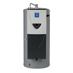
COMMERCIAL GAS WATER HEATER
• For Your Safety •
AN ODORANT IS ADDED TO THE GAS USED
BY THIS WATER HEATER.
MODELS (A/S/M) TX-199
SERIES 100 & 101
INSTALLATION - OPERATION -
SERVICE - MAINTENANCE
Read and understand this instruction
manual and the safety messages
herein before installing, operating or
servicing this water heater.
Failure to follow these instructions and
safety messages could result in death
or serious injury.
This manual must remain with the
water heater.
Instruction Manual
R
DR
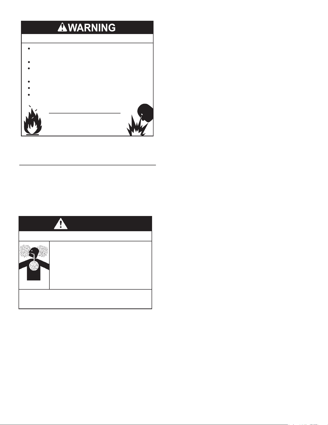
WARNING: If the information in these
instructions is not followed exactly, a fire
or explosion may result causing property
damage, personal injury or death.
Do not store or use gasoline or other
flammable vapors and liquids in the
vicinity of this or any other appliance.
WHAT TO DO IF YOU SMELL GAS:
Do not try to light any appliance.
Do not touch any electrical switch; do
not use any phone in your building.
Immediately call your gas supplier
from a neighbor’s phone. Follow the
gas supplier’s instructions.
If you cannot reach your gas supplier,
call the fire department.
Installation and service must be
performed by a qualified installer,
service agency or the gas supplier.
•
•
•
•
PRINTED 0118
Thank you for buying this energy efcient water heater.
We appreciate your condence in our products.

2
TABLE OF CONTENTS
GENERAL SAFETY INFORMATION ..........................................4
Precautions ............................................................................4
Grounding Instructions ...........................................................4
Hydrogen Gas Flammable .....................................................4
INTRODUCTION ........................................................................6
Abbreviations Used ................................................................6
Qualications ..........................................................................6
Preparing for the Installation ..................................................6
FEATURES AND COMPONENTS .............................................7
Basic Operation ......................................................................7
INSTALLATION CONSIDERATIONS .......................................10
Rough-In Dimensions ...........................................................10
Locating the Water Heater ...................................................11
Vent Piping Options ..............................................................12
Hard Water ...........................................................................12
Circulation Pumps ................................................................12
INSTALLATION REQUIREMENTS ..........................................13
Gas Supply Pressure Requirements ....................................13
Supply Gas Regulator ..........................................................14
Power Supply .......................................................................14
Mixing Valves .......................................................................14
Dish-washing Machines .......................................................15
Closed Water Systems .........................................................15
Thermal Expansion ..............................................................15
Safety Valve Requirements ..................................................16
Condensate Drain ................................................................17
Combustible Material Storage ..............................................17
Ventilation Requirements .....................................................18
Direct Vent Installations ........................................................22
Single-Vent Installations .......................................................23
Stainless Steel Vent Installations .........................................24
Common Direct Venting Requirements ................................26
Common Direct-Venting System ..........................................26
Concentric Termination Installation Preparation ...................28
Air Requirements .................................................................30
INSTALLATION REQUIREMENTS - COMMONWEALTH OF
MASSACHUSETTS ..................................................................32
Installing Carbon Monoxide Detectors .................................32
Approved Carbon Monoxide Detectors ................................32
Signage ................................................................................32
Inspection .............................................................................32
Exemptions ..........................................................................32
Manufacturer Requirements - Gas Equipment Venting
System Provided ..................................................................32
Manufacturer Requirements - Gas Equipment Venting
System Not Provided ...........................................................32
HIGH-ALTITUDE INSTALLATIONS ..........................................33
Termination Clearances for Sidewall Installations ................34
Clearances For Rooftop Terminations ..................................36
WATER HEATER INSTALLATION .........................................37
Water Heating Unit Condensate Drain .............................. 37
Supply Gas Line Installation ..............................................39
Measuring Inlet Gas Pressure ...........................................42
Supply Gas Pressure Adjustment .....................................42
Gas Line Connection .........................................................43
Gas Line Leak Testing .......................................................43
Purging .............................................................................. 43
Electrical Connections .......................................................43
Water Line Connections .................................................... 44
T&P Valve Discharge Pipe ................................................44
TEMPERATURE REGULATION ...........................................46
High Temperature Limit Control (ECO) .............................46
Thermostat Control ...........................................................46
Firing Rate Modulation ......................................................46
High Temperature Applications .........................................46
CONTROL SYSTEM OPERATION .......................................47
Temperature Remote Controller ........................................47
START UP .............................................................................49
Prior to Start up .................................................................49
Initial Operation .................................................................49
Flow Rates ........................................................................49
Lighting the Water Heater .................................................50
Normal Operation .............................................................. 52
Setting the Outlet Water Temperature ............................... 52
Default Outlet Temperature ...............................................53
Setting Units of Measure ................................................... 53
Freeze Protection System ................................................. 53
TROUBLESHOOTING ..........................................................54
Installation Checklist .........................................................54
Operational Problems .......................................................54
Replacement Parts ............................................................56
General Fault and Alert Conditions ...................................56
Troubleshooting Chart .......................................................57
Error Codes ....................................................................... 58
Water Heating Unit Controller Fault and Alert Conditions . 59
MAINTENANCE ....................................................................61
General .............................................................................61
Precautions .......................................................................61
Water heating unit Maintenance and Service....................61
Drain Valve ........................................................................ 63
Vent System Maintenance ................................................63
DIAGRAMS ...........................................................................64
Wiring Diagram .................................................................64
Circulation Pump Wiring Diagrams ...................................65
Water Piping Diagrams .....................................................66
3
SAFE INSTALLATION, USE, AND SERVICE
The proper installation, use, and servicing of this water heater is extremely important to your safety and the safety of
others.
Many safety-related messages and instructions have been provided in this manual and on your own water heater to
warn you and others of a potential injury hazard. Read and obey all safety messages and instructions throughout this
manual. It is very important that the meaning of each safety message is understood by you and others who install, use,
or service this water heater.
All safety messages will generally tell you about the type of hazard, what can happen if you do not follow the safety
message, and how to avoid the risk of injury.
DANGER
WARNING
CAUTION
CAUTION
DANGER indicates an imminently
hazardous situation which, if not avoided,
will result in injury or death.
This is the safety alert symbol. It is used to alert you to
potential personal injury hazards. Obey all safety
messages that follow this symbol to avoid possible
injury or death.
WARNING indicates a potentially hazardous
situation which, if not avoided, could result
in injury or death.
CAUTION indicates a potentially hazardous
situation which, if not avoided, could result in
minor or moderate injury.
CAUTION used without the safety alert
symbol indicates a potentially hazardous
situation which, if not avoided, could result in
property damage.
APPROVALS
R
DR
4
PRECAUTIONS
DO NOT USE THIS WATER HEATER IF ANY PART HAS
BEEN EXPOSED TO FLOODING OR WATER DAMAGE.
Immediately call a qualied service agency to inspect the
water heater and to make a determination on what steps
should be taken next.
If the unit is exposed to the following, do not operate heat-
er until all corrective steps have been made by a qualied
service agency.
1. External re.
2. Damage.
3. Firing without water.
GROUNDING INSTRUCTIONS
This water heater must be grounded in accordance with
the National Electrical Code and/or local codes. These
codes must be followed in all cases. Failure to ground this
water heater properly may also cause erratic control system
operation.
This water heater must be connected to a grounded metal,
permanent wiring system; or an equipment grounding
conductor must be run with the circuit conductors and
connected to the equipment grounding terminal or lead on
the water heater.
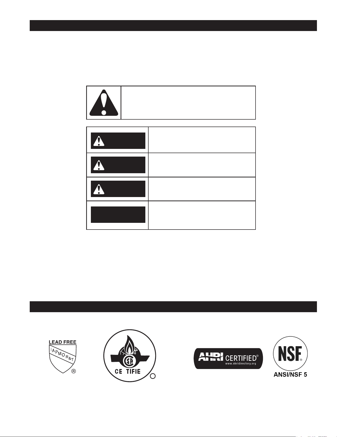
HYDROGEN GAS FLAMMABLE
Explosion Hazard
Flammable hydrogen gases
may be present.
Keep all ignition sources away
from faucet when turning on
hot water.
Hydrogen gas can be produced in a hot water system
served by this water heater that has not been used for a
long period of time (generally two weeks or more). Hydrogen
gas is extremely ammable. To reduce the risk of injury
under these conditions, it is recommended that a hot water
faucet served by this water heater be opened for several
minutes before using any electrical appliance connected
to the hot water system. If hydrogen is present there will
probably be an unusual sound such as air escaping through
the pipe as the water begins to ow. THERE SHOULD BE
NO SMOKING OR OPEN FLAME NEAR THE FAUCET AT
THE TIME IT IS OPEN.
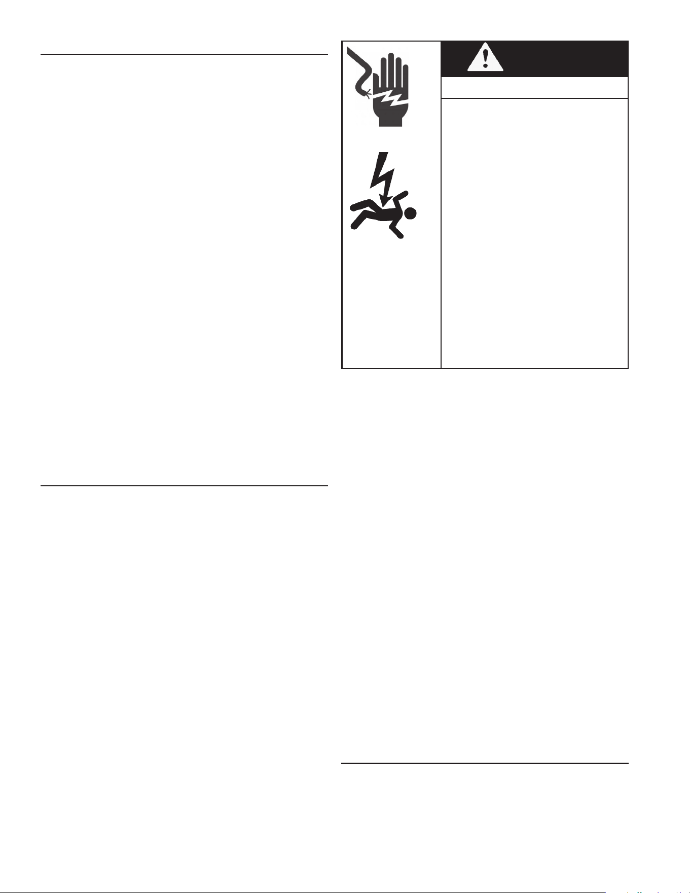
GENERAL SAFETY INFORMATION
Verify the power to the water heater is turned off before performing any service
procedures. The Enable /Disable switch on front panel disables the 24-volt gas valve.
Electrical supply must be turned off at circuit breaker serving water heater.
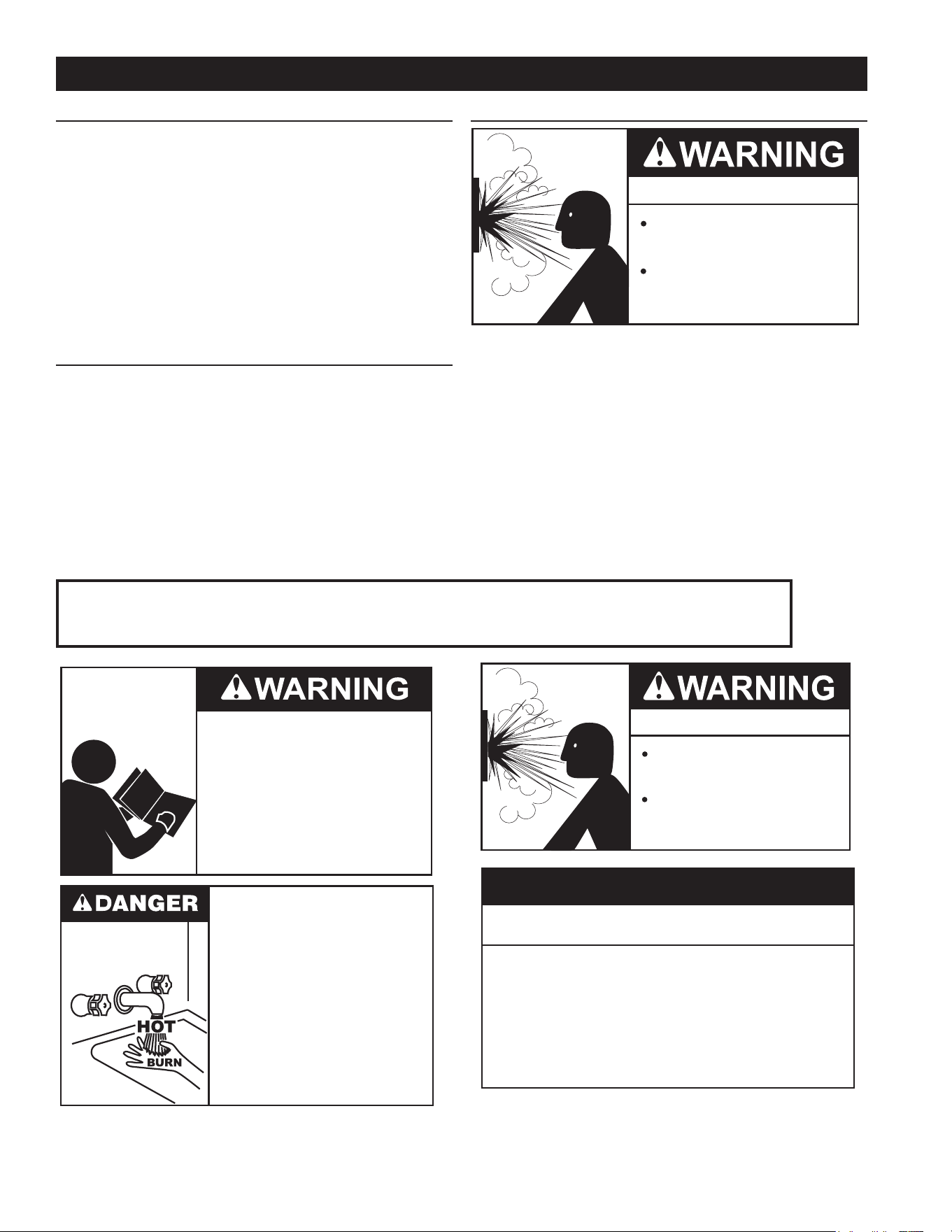
Read and understand this instruction
manual and the safety messages
herein before installing, operating or
servicing this water heater.
Failure to follow these instructions and
safety messages could result in death
or serious injury.
This manual must remain with the
water heater.
Water temperature over 125°F (52°C)
can cause severe burns instantly
resulting in severe injury or death.
Children, the elderly and the
physically or mentally disabled are at
highest risk for scald injury.
Feel water before bathing or
showering.
Temperature limiting devices such as
mixing valves must be installed
when required by codes and to
ensure safe temperatures at fixtures.
Explosion Hazard
Overheated water can cause
water tank explosion.
Properly sized temperature and
pressure relief valve must be
installed in the opening provided.
Improper installation, use and service may result
in property damage.
Do not operate water heater if exposed to flooding or
water damage.
•
Inspect anode rods regularly, replace if damaged.
•
Install in location with drainage.
•
Fill tank with water before operation.
•
Properly sized thermal expansion tanks are required on all
closed water systems.
•
Refer to this manual for installation and service.
CAUTION
5
Fire or Explosion Hazard
Read instruction manual before
installing, using or servicing
water heater.
Avoid all ignition sources if you smell gas.
Do not store or use gasoline or other flammable vapors and
liquids in the vicinity of this or any other appliance.
Use only the gas shown on the water heater rating label.
Keep ignition sources away from faucets after extended
periods of non-use.
Maintain required clearances to combustibles.
Do not expose water heater controls to excessive gas
pressure.
Do not obstruct water heater air intake
with insulating blanket.
Gas and carbon monoxide detectors
are available.
Install water heater in accordance with
the instruction manual.
Breathing carbon monoxide can cause brain damage or
death. Always read and understand instruction manual.
Breathing Hazard - Carbon Monoxide Gas
Property Damage Hazard
All water heaters eventually leak.
•
Do not install without adequate drainage.
•
CAUTION
Turn off power at the branch circuit
breaker serving the water heater
before performing any service.
Electrical Shock Hazard
•
Label all wires prior to disconnecting
when performing service. Wiring errors
can cause improper and dangerous
operation.
•
Verify proper operation after servicing.
•
Failure to follow these instructions can
result in personal injury or death.
•
Fire Hazard
Do not install water heater on
carpeted floor.
Do not operate water heater if
exposed to flooding or water
damage.
For continued protection against
risk of fire:
Fire and Explosion Hazard
Leak test gas connections before
placing water heater in operation.
Disconnect gas piping at main
gas shutoff valve before leak
testing heater.
Install sediment trap in
accordance with NFPA 54 or
CAN/CSA B149.1.
Use joint compound or Teflon tape
compatible with propane gas.
Fire and Explosion Hazard
Turn off gas lines during installation.
Contact a qualified installer or service
agency for installation and service.
Excessive gas pressure to gas valve can
cause serious injury or death.
Do not use water heater with any gas
other than the gas shown on the rating
label.
Jumping out control circuits or components can
result in property damage, personal injury or death.
Service should only be performed by a qualified service
technician using proper test equipment.
•
Altering the water heater controls and/or wiring in any way
could result in permanent damage to the controls or water
heater and is not covered under the limited warranty.
•
Any bypass or alteration of the water
heater controls and/or wiring will result
in voiding the appliance warranty.

6
Thank You for purchasing this water heater. Properly
installed and maintained, it should give you years of trouble
free service.
ABBREVIATIONS USED
Abbreviations found in this Instruction Manual include :
• ANSI - American National Standards Institute
• ASME - American Society of Mechanical Engineers
• AHRI - Air Conditioning, Heating and Refrigeration
Institute
• NEC - National Electrical Code
• NFPA - National Fire Protection Association
• UL - Underwriters Laboratory
• CSA - Canadian Standards Association
QUALIFICATIONS
Installation and service of this water heater requires ability
equivalent to that of a Qualied Agency (as dened by
ANSI below) in the eld involved. Installation skills such
as plumbing, air supply, venting, gas supply and electrical
supply are required in addition to electrical testing skills
when performing service.
ANSI Z223.1 2015 Sec. 3.3.81: “Qualied Agency” - “Any
individual, rm, corporation or company that either in person
or through a representative is engaged in and is responsible
for (a) the installation, testing or replacement of gas piping
or (b) the connection, installation, testing, repair or servicing
of appliances and equipment; that is experienced in such
work; that is familiar with all precautions required; and that
has complied with all the requirements of the authority
having jurisdiction.”
If you are not qualied (as dened by ANSI above) and
licensed or certied as required by the authority having
jurisdiction to perform a given task do not attempt to perform
any of the procedures described in this manual. If you do
not understand the instructions given in this manual do not
attempt to perform any procedures outlined in this manual.
PREPARING FOR THE INSTALLATION
1. Read the entire manual before attempting to install or
operate the water heater. Pay close attention to the
General Safety Information (page 4). If you don’t
follow the safety rules, the water heater may not operate
safely. It could cause property damage, injury and/or
death.
• This manual contains instructions for the installation,
operation, and maintenance of the water heater. It
also contains warnings throughout the manual that
you must read and be aware of. All warnings and all
instructions are essential to the proper operation of
the water heater and your safety.
• Detailed installation diagrams are also found in
this manual. These diagrams will serve to provide
the installer with a reference. It is essential that
all venting, water piping, gas piping, and wiring be
installed as shown.
INTRODUCTION
• Particular attention should be given to the installation
of thermometers at the locations indicated in the
piping diagrams as these are necessary for checking
the operation of the water heater.
• The principal components of the water heater are
identified in Features and Components (page
7) in this manual. Use this reference to locate
and identify various components on the water heater.
• See Troubleshooting (page 54). By using this
checklist the user may be able to make minor
operational adjustments and avoid unnecessary
service calls. However, service and diagnostic
procedures should be performed only by a Qualied
Service Agency.
NOTE: Costs to correct installation errors are
not covered under the limited warranty. See the
Commercial Water Heater Limited Warranty provided
with this water heater.
2. Be sure to turn off power when working on or near
the electrical system of the water heater. Never touch
electrical components with wet hands or when standing
in water.
3. The installation must conform to all instructions contained
in this manual and the local code authority having
jurisdiction. These shall be carefully followed in all cases.
Authorities having jurisdiction should be consulted before
installation begins if there are any questions regarding
compliance with local, state or national codes.
• In the absence of local codes, the installation must
comply with the current editions of the National Fuel
Gas Code, ANSI Z223.1/NFPA 54 and the National
Electrical Code, NFPA 70 or CAN/CSA-B149.1,
the Natural Gas and Propane Installation Code,
and CSA C22.1, the Canadian Electrical Code.
All documents are available from the Canadian
Standards Association, Corporate Head Ofce 178
Rexdale Blvd.Toronto, ONCanada M9W 1R3.
• NFPA documents are also available from the National
Fire Protection Association, 1 Batterymarch Park,
Quincy, MA 02269.
4. After reading this manual, if you have any questions or
do not understand any portion of the instructions, call
the toll free number on the back cover of this manual for
technical assistance. In order to expedite your request,
please have the full Model, Serial and Series numbers
of the water heater you are working with available for
the technician. This information is located on the water
heater’s rating label.
5. Carefully plan the placement of the water heater.
Examine the location to ensure that it complies with the
requirements in Locating the Water Heater (page 11)
and the Rough-In Dimensions (page 10).
7
6. For installation in California this water heater must be
braced or anchored to avoid falling or moving during
an earthquake. See instructions for correct installation
procedures. Instructions may be obtained from California
Ofce of the State Architect, 1102 Q Street, Suite 5100,
Sacramento, CA 95811.
FEATURES AND COMPONENTS
BASIC OPERATION
This gas water heater combines features of a conventional
tank water heater and a tankless water heater to achieve
high efficiency as well as high-volume on-demand
availability.
When hot water is being used, hot water is drawn from
the top of the storage tank. As the tank water is used, it is
replenished by cold water from the water supply through
the cold water inlet at the bottom of the tank. When the
temperature of the water in the storage tank falls below
a set point, the controller runs the pump, which draws
cold water from either the bottom of the tank or the supply
(depending on the hot water draw ow), sends it through
the tankless heater, and then to the hot water outlet tting
at the top of the tank.
If hot water is being used, the heated water moves through
the outlet tting to the faucet or appliance. If demand for hot
water is high enough, additional hot water is drawn from the
top of the tank. If hot water is not being used, the heated
water from the tankless unit recirculates back into the tank
at the top until the temperature in the tank reaches the set
point. See Figure 3.
1
2
3
2
4
5
6
7
8
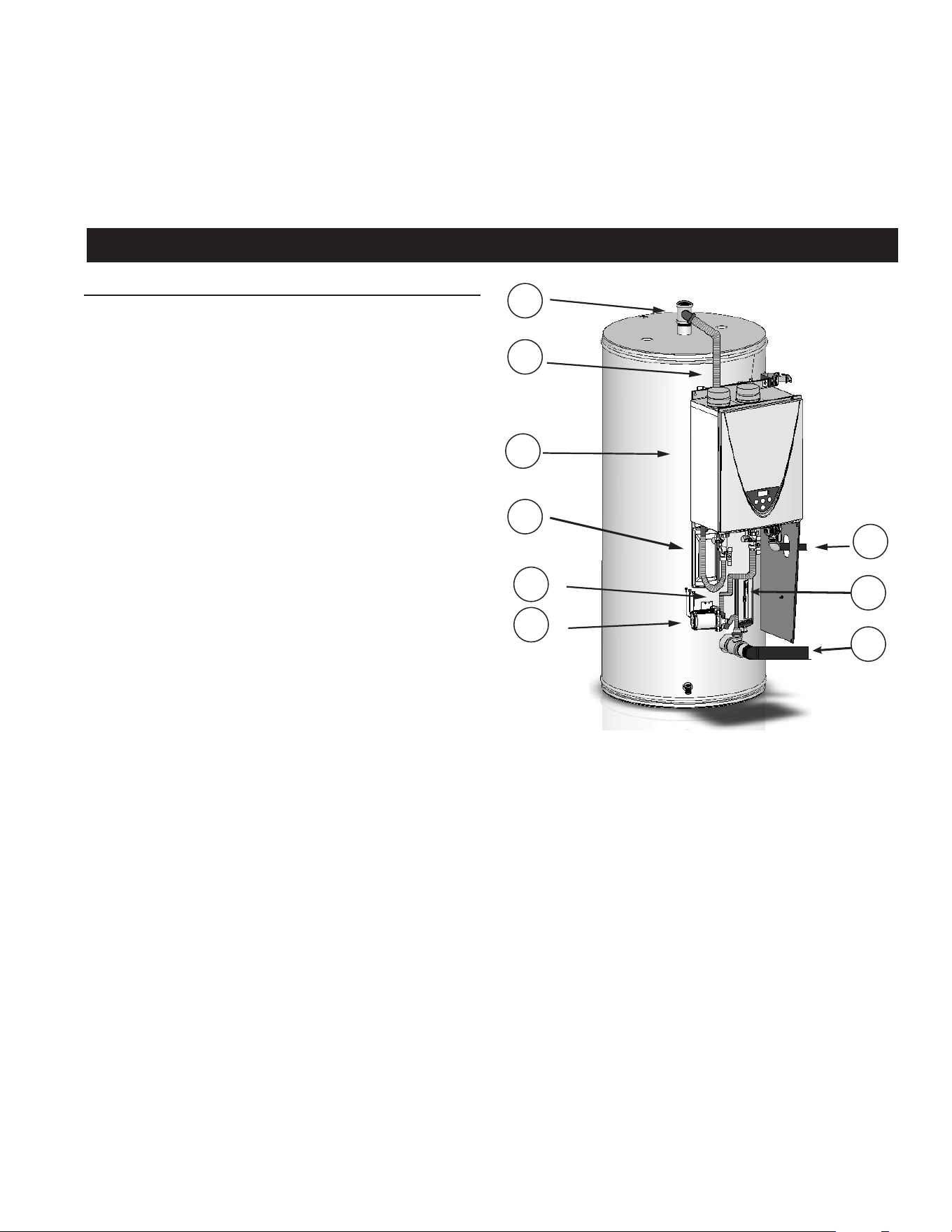
Figure 1. TX1 Components
1. Hot Water Outlet Fitting
2. Piping from Water Heating Unit to Tank
3. Water Heating Unit
4. Piping from Tank to Pump
5. Pump
6. Cold Water Inlet
7. Controller
8. Gas Supply
7. Massachusetts Code requires this water heater to be
installed in accordance with Massachusetts 248-CMR
2.00: State Plumbing Code and 248-CMR 5. See
Installing Carbon Monoxide Detectors (page 32).
8
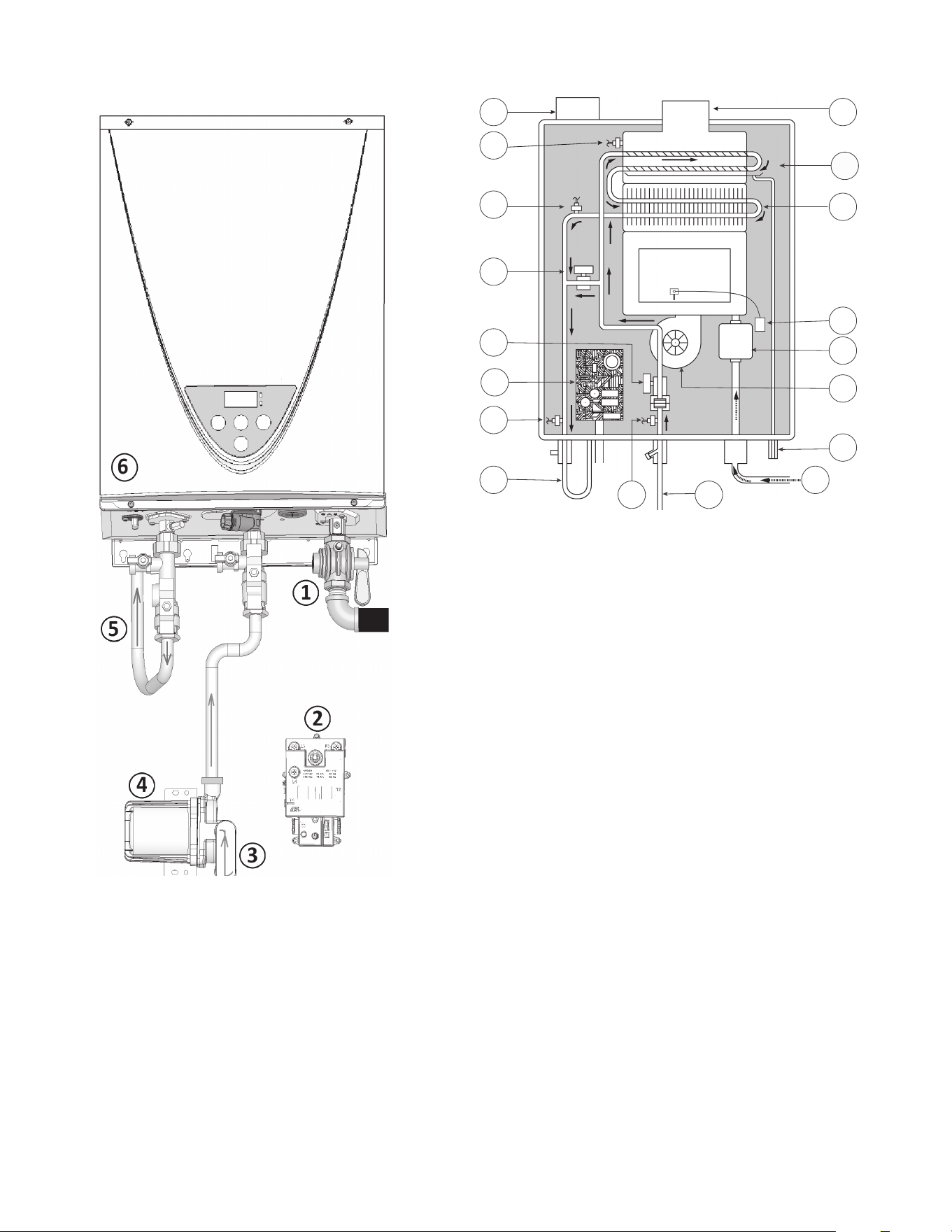
Figure 2. Water Heater Function
1. Gas Supply Valve
2. Controller
3. Cold Water from Bottom of Tank
4. Pump
5. Piping to Outlet Fitting
6. Water Heating Unit
WATER HEATING UNIT COMPONENTS
1
2
3
4
5
6
7
8
9 10
11
12
13
14
15
16
18
17
Figure 3. Water Heating Unit
1. Combustion Air Intake Port
2. Exhaust Thermistor
3. Heated Water Thermistor
4. Bypass Valve
5. Water Control Valve
6. Computer Board
7. Hot Water Outlet Thermistor
8. Piping to Outlet Fitting
9. Cold Water Inlet Thermistor
10. Cold Water Inlet
11. Gas Supply Inlet
12. Condensate Drain Port
13. Fan Motor
14. Gas Control Valve
15. Igniter
16. Primary Heat Exchanger
17. Secondary Heat Exchanger
18. Exhaust Port
9
1
2
3
5
7
8
9
6
4
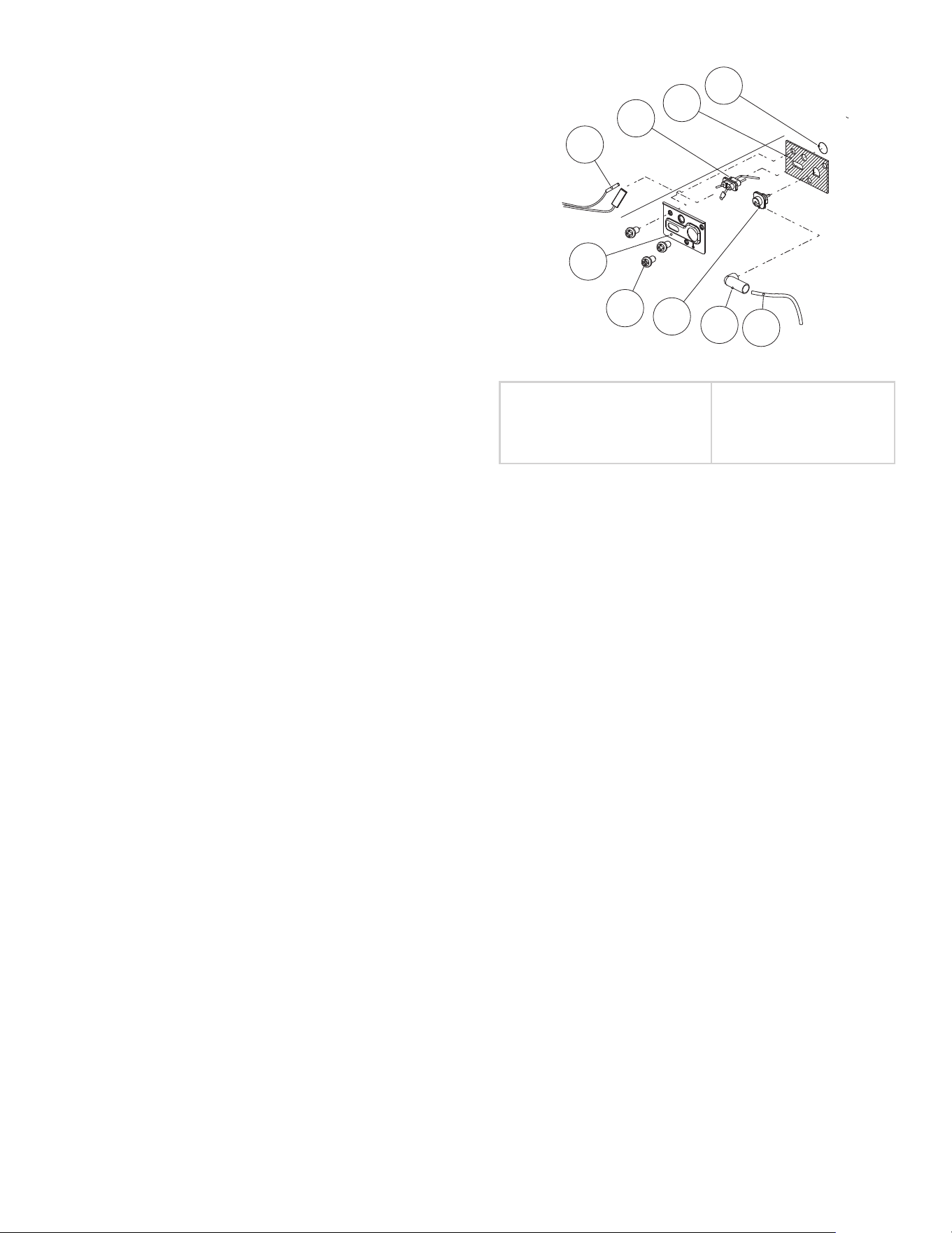
Figure 4. Igniter Assembly
1. Burner Window
2. Rod holder gasket
3. Flame rod
4. Flame rod wire
5. Rod holder
6. Pan screw M4x8 MFZN
7. Igniter rod
8. Rod cap
9. Igniter assembly
Flame Sensor
The control system also monitors the ame sensor to
conrm a ame is present at the main burner. If a ame is
not veried during the ignition trial period (3-5 seconds) the
control system will immediately close the gas valve.
MODULATION
The water heaters covered by this manual are capable
of modulating their ring rate. The function of the water
heating unit is controlled by a computer printed circuit
board. The computer monitors the water temperature
measured by the cold water inlet thermistor and hot water
outlet thermistor.
Another controller monitors the temperature in the tank. If
the tank temperature falls below the set point, this controller
runs the pump. As cold water from the bottom of the tank
runs into the water heating unit, the thermistors will detect
the change in temperature. When the temperatures fall
below the set point, the burner is ignited, heating it until
the thermistors in the water heating unit and in the tank
warm to their set points.
BURNER ASSEMBLY
Spark Igniter
The control system energizes the spark ignition transformer
with 120 VAC during the ignition cycle. The spark ignition
transformer then sends a high-voltage current to the spark
igniter which in turn ignites the main burner air/gas mixture.
10
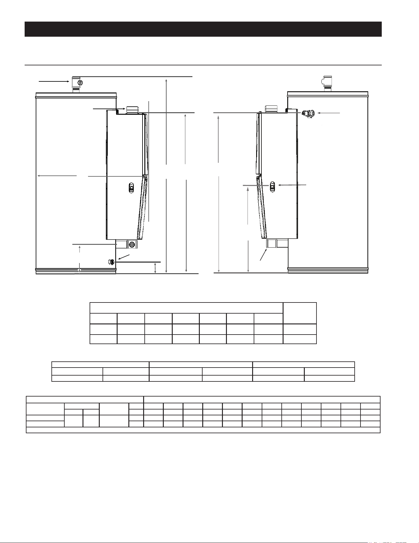
ROUGH-IN DIMENSIONS
E
A
F
Combustion Air Inlet
and Exhaust Outlet
Hot Water Outlet
Drain
Valve
C
D
B
G
T&P Valve
Supply Gas Connection
Cold Water
Inlet
Figure 5. Rough-in Dimensions
Table 1. Dimensions
APPROX.
SHIP WEIGHT
A B C D E F G
Inches (cm) Inches (cm) Inches (cm) Inches (cm) Inches (cm) Inches (cm) Inches (cm) LBS (KG)
72 (183) 58.7 (149) 41 (104) 11.8 (30) 4.3 (11) 61.38 30 (76) 520(236)
Table 2. GAS PRESSURE REQUIREMENTS
*Manifold Pressure Minimum Supply Pressure Maximum Supply Pressure
NATURAL GAS PROPANE GAS NATURAL GAS PROPANE GAS NATURAL GAS PROPANE GAS
2.95" W.C. (0.73 kPa) 3.3" W.C. (0.82 kPa) 4.0” W. C. (1.00 kPa) 8.0” W. C. (1.99 kPa) 10.5” W. C. (2.61 kPa) 14” W. C. (3.49 kPa)
Table 3. RECOVERY CAPACITIES
U. S. Gallons/hr & liters/hr at temperature rise indicated
Type of
Gas
Input
Thermal
Efciency%
°F 30°F 40°F 50°F 60°F 70°F 80°F 90°F 100°F 110°F 120°F* 130°F* 140°F*
Btu/hr kW °C 17°C 22°C 28°C 33°C 39°C 44°C 50°C 56°C 61°C 67°C 72°C 78°C
Natural
199000 58.32 96
GPH 772 579 463 386 331 289 257 232 211 193 178 165
Propane LPH 2922 2192 1753 1461 1253 1094 973 878 799 731 674 625
* inlet water 40° F (22° C)
Water Connection Size: Inlet/Outlet 2" Female NPT
Supply Gas Connection: 3/4" Male NPT
INSTALLATION CONSIDERATIONS
11
Fire or Explosion Hazard
Read instruction manual before
installing, using or servicing
water heater.
Avoid all ignition sources if you smell gas.
Do not store or use gasoline or other flammable vapors and
liquids in the vicinity of this or any other appliance.
Use only the gas shown on the water heater rating label.
Keep ignition sources away from faucets after extended
periods of non-use.
Maintain required clearances to combustibles.
Do not expose water heater controls to excessive gas
pressure.
9. There is a risk in using fuel burning appliances such
as gas water heaters in rooms, garages or other areas
where gasoline, other ammable liquids or engine driven
equipment or vehicles are stored, operated or repaired.
Flammable vapors are heavy and travel along the oor
and may be ignited by the water heater’s igniter or Main
Burner ames causing re or explosion.
10. Flammable items, pressurized containers or any other
potential re hazardous articles must never be placed
on or adjacent to the water heater.
CLEARANCE TO COMBUSTIBLE MATERIALS
The water heaters covered in this manual are approved
for installation on combustible ooring. The clearance to
combustible and non combustible construction materials
is zero inches on the back and sides of the water heater.
These water heaters are also approved for installation in
an alcove.
There is a three inch (76 mm) clearance from the left and
right sides of the water heating unit to combustible and
non-combustible surfaces.
LOCATING THE WATER HEATER
Carefully choose a location for the new water heater. The
placement is a very important consideration for the safety of
the occupants in the building and for the most economical
use of the water heater.
Property Damage Hazard
All water heaters eventually leak.
•
Do not install without adequate drainage.
•
CAUTION
Whether replacing an existing water heater or installing
the water heater in a new location observe the following
critical points:
1. The water heater must not be located in an area where
it will be subject to freezing temperatures.
2. Locate the water heater so it is protected and not subject
to physical damage by a moving vehicle.
3. Locate the water heater on a level surface.
4. Locate the water heater near a oor drain. The water
heater should be located in an area where leakage of
the tank or connections will not result in damage to the
area adjacent to the water heater or to lower oors of
the structure. When such locations cannot be avoided,
it is recommended that a metal drain pan, adequately
drained, be installed under the water heater.
5. Locate the water heater close to the point of major hot
water usage.
6. Locate the water heater close to a 120 VAC power supply.
See Power Supply (page 14) for requirements.
7. Locate the water heater where an adequate supply of
fresh air for combustion and ventilation can be obtained.
See Air Requirements (page 30).
8. Locate the water heater where the vent and intake air
piping, when installed, will remain within the maximum
equivalent lengths allowed. See Maximum Equivalent
Pipe Lengths and Elbows (page 21).
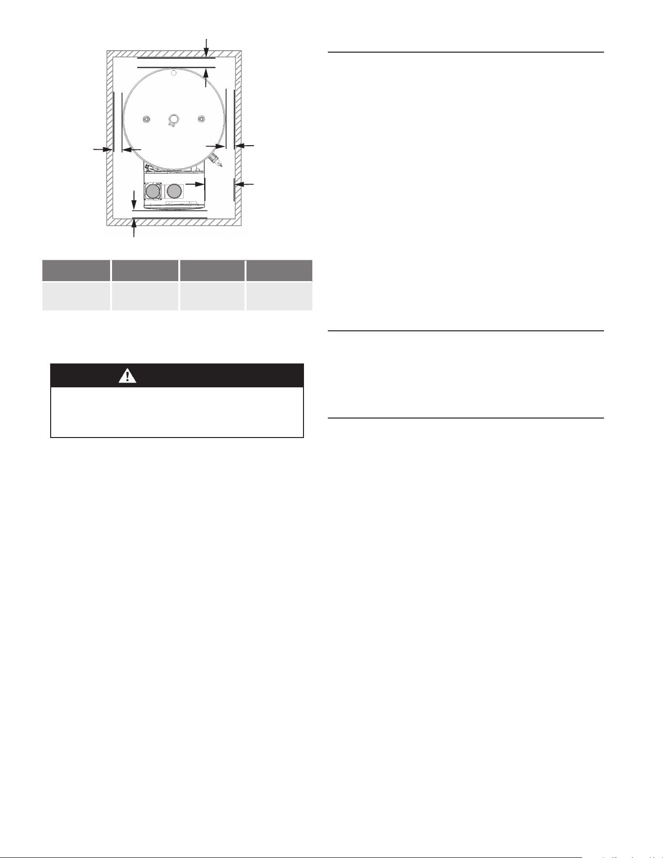
12
0” Min.
0” Min.
4” Min.
0” Min.
3” Min.
Figure 6. Clearances
Top Bottom Front Sides
4 in. (102 mm) 0 in. (0 mm) 4 in. (102 mm) 0 in. (0 mm)
Note: Adequate clearance for servicing
should be maintained on all installations.
See Service Clearance.
WARNING
Maintain all clearances around the water heater. Fail-
ure to do so could create a re hazard, potentially
leading to death, serious injury, and/or property
damage.
When the water heater is installed directly on carpeting, the
water heater shall be installed on a metal or wood panel
extending beyond the full width and depth of the water
heater by at least three inches (76.2 mm) in any direction
or, if the water heater is installed in an alcove or closet, the
entire oor shall be covered by the panel. The panel must
be strong enough to carry the weight of the heater when
full of water.
SERVICE CLEARANCE
A service clearance of 24 inches (61 cm) should be
maintained from serviceable parts such as the T&P
valve, control system components, gas valve, drain
valve. A service clearance of 50 inches (127 cm) should
be maintained from top for anode replacement.
INTAKE AIR AND VENT PIPE CLEARANCES
The minimum clearance from combustible materials for the
vent (exhaust) and intake air piping shall be 0 inches. Vent
or intake air piping passing through a combustible wall or
ceiling must be a continuous run (no joints).
VENT PIPING OPTIONS
EXTENDED VENT LENGTH
The water heaters covered by this manual can be installed
using four-inch pipe for the intake air and/or vent piping up
to a maximum of 120 equivalent feet (15.2 m).
Vent terminations are supplied with the heater.
All runs must comply with Table 7 (page 21).
Contact your local supplier or the parts department to order
vent terminals.
OPTIONAL DIRECT VENT TERMINATIONS
The water heaters covered in this manual can be installed
in a direct vent conguration using optional concentric
terminations. See Concentric Termination Installation
Preparation (page 28).
Concentric terminations must be ordered separately.
Contact your local distributor or call the parts department
phone number listed on the back cover of this manual to
order.
HARD WATER
Where hard water conditions exist, water softening or the
threshold type of water treatment is recommended. This will
protect the dishwashers, coffee urns, water heaters, water
piping and other equipment. See Maintenance (page 61)
for sediment and lime scale removal procedures.
CIRCULATION PUMPS
A circulating pump is used when a system requires a
circulating loop or there is a storage tank used in conjunction
with the water heater. See Water Piping Diagrams (page
66) for installation location of circulating pumps.
When the water heater is used with a building recirculation
system, the building recirculation ow should be no greater
than 1 GPM. Also, for maximum energy efciency, the
recirculation system should be on a timer so that it won’t
run continuously without actual hot water usage.
See Circulation Pump Wiring Diagrams (page 65) for
electrical hookup information. Install in accordance with the
current edition of the National Electrical Code, NFPA 70
or the Canadian Electrical Code, CSA C22.1.
Stainless steel circulating pumps are recommended for use
with commercial water heaters.
Refer to the circulating pump manufacturer’s instructions
for its operation, lubrication, and maintenance instructions.
13
WARNING
Breathing, Fire, and
Explosion Hazard
Do not use this water heater with any
gas other than the one listed on the
rating plate.
Ensure that any and all gas regulators
used are operating properly and provid-
ing gas pressures within the specied
range shown below. Excess gas inlet
pressure may cause serious accidents.
Conversion of this unit from natural gas
to propane or vice versa will void all
warranties. Contact your local distribu-
tor to get the correct unit for your gas
type. The manufacturer is not liable for
any property and/or personal damage
resulting from gas conversions.
Failure to observe these warnings
could result in severe personal injury,
carbon monoxide poisoning, or death.
The following are the minimum and maximum gas pressures
required by all models of this appliance:
Table 4. Gas Pressure Parameters by Gas Type
Gas type Inlet Gas Pressure
Natural Gas
Min. 4.0” W.C. (1.00 kPa)
Max. 10.5” W.C. (2.61 kPa)
Propane
Min. 8.0” W.C. (1.99 kPa)
Max. 14.0” W.C. (3.48 kPa)
Note: Fuel conversions are not allowed on this product.
The gas valve has minimum gas supply pressure limits
specied in Table 4. The minimum supply pressure is
measured while gas is owing (dynamic pressure). The
supply pressure should never fall below the minimum
specied in the table for each type of gas.
The supply pressure should be measured with all gas
red appliances connected to the common main ring at
full capacity. If the supply pressure drops more than 1.5”
W.C. as gas begins to ow to the water heater, then the
supply gas system, including the gas line and/or the gas
regulator may be restricted or undersized. See Supply Gas
Regulator (page 14).
The gas valve has maximum gas supply pressure limits
specied in Table 4. The maximum supply pressure is
measured while gas is not owing (static pressure).
Until testing of the main gas line supply pressure is
completed, ensure the gas line to the water heater is
disconnected to avoid any damage to the water heater.
INSTALLATION REQUIREMENTS
GAS SUPPLY PRESSURE REQUIREMENTS
Low-pressure gas supply systems are dened as those
systems that cannot under any circumstances exceed
14” W.C. (1/2 PSI Gauge). These systems do not require
pressure regulation. Measurements should be taken to
insure that gas pressures are stable and fall within the
requirements stated on the water heater rating plate. Take
the measurements with all gas burning equipment off (static
pressure) and with all gas burning equipment running at
maximum rate (dynamic pressure). The gas supply pressure
must be stable within 1.5” W.C. from static to dynamic
pressure for best performance. Pressure drops that exceed
1.5” W.C. may cause rough starting, noisy combustion or
nuisance outages. Increases or spikes in static pressure
during off cycles may cause failure to ignite or in severe
cases damage to appliance gas valves. If your low-pressure
system does NOT meet these requirements, the installer is
responsible for the corrections.
High Pressure supply systems use pressures that exceed
14” W.C. (1/2 PSI Gauge). These systems must use eld-
supplied regulators to lower the gas pressure to less than
14” W.C. (1/2 PSI Gauge). Water heaters require gas
regulators that are properly sized for the water heater
input and deliver the rating-plate specied pressures. Gas
supply systems in which the pressure exceeds 5 PSI often
require multiple regulators to achieve desired pressures.
Systems in excess of 5 PSI pressure should be designed
by gas delivery professionals for best performance. Water
heaters connected to gas supply systems that exceed 14”
W.C. (1/2 PSI Gauge) at any time must be equipped with
a gas supply regulator.
14
SUPPLY GAS REGULATOR
1. The maximum allowable gas supply pressure for this
water heater using either natural gas or propane is
specified in Table 4. Install a positive lock-up gas
pressure regulator in the gas supply line if inlet gas
pressure can exceed these pressures at any time.
2. If a positive lock-up regulator is required, follow these
instructions:
a. Positive lock-up gas pressure regulators must be
capable of going low enough to support the unit at
its lowest ring rate.
b. Positive lock-up gas pressure regulators must be
rated at or above the input Btu/hr rating of the water
heater they supply.
c. Supply gas regulators shall have inlet and outlet
connections not less than the minimum supply gas
line size for the water heater they supply. See Table
19 (page 41) and Table 20 (page 41).
d. Positive lock-up gas pressure regulator(s) should
be installed no closer than 3 feet (1 meter) and
no farther than 8 feet (2.4 meters) from the water
heater’s inlet gas connection.
e. After installing the positive lock-up gas pressure
regulator(s), an initial nominal supply pressure
setting of 7.0” W.C. for natural gas and 10"w.c. for
propane gas while the water heater is operating is
recommended and will generally provide good water
heater operation. Some additional adjustments may
be required later to maintain a steady gas supply
pressure.
f. When installing multiple water heaters in the same
gas supply system, it is recommended that individual
positive lock-up gas pressure regulators be installed
at each unit from the supply gas connection on the
water heater.
POWER SUPPLY
The water heaters covered in this manual require a 120
VAC, 1Ø (single phase), 60 Hz, 15 amp power supply
and must also be electrically grounded in accordance
with local codes or, in the absence of local codes, with the
National Electrical Code, ANSI/NFPA 70 or the Canadian
Electrical Code, CSA C22.1.
WARNING
Shock or Electrocution Hazard
Follow the electrical code
requirements of the local authority
having jurisdiction. In the absence of
such requirements, follow the current
edition of the National Electrical
Code ANSI/NFPA 70 in the U.S.
or the current edition of CSA C22.1
Canadian Electrical Code Part 1
in Canada.
When servicing or replacing parts
within the water heater, label all wires
prior to disconnection to facilitate an
easy and error-free reconnection.
Wiring errors can cause improper
and dangerous operation. Verify
proper operation after servicing.
Failure to observe these warnings
could result in personal injury or
death.
DEDICATED POWER WIRING AND BREAKERS
Dedicated power supply wires, neutral wires, ground wiring,
and dedicated circuit breakers, often prevent electrical line
noise and are required when installing the water heater.
NOTE: This water heater should not be connected to an
electrical supply with a Ground Fault Circuit Interrupter
(GFCI) or Arc Fault Circuit Interrupter (AFCI) with Integral
GFCI protection as dened in NFPA 70, CSA C22.1 and
UL 943.
POWER FLUCTUATIONS AND ELECTRICAL NOISE
The water heater’s control system requires a source of stable
clean electricity for proper operation. Connecting the water
heater to a branch circuit that is subject to uctuations in
voltage level or electrical line noise such as electromagnetic
interference (EMI) or radio frequency interference (RFI) may
cause erratic control system operation and malfunction.
A high-quality power supply filter/suppressor must be
installed if the above conditions exist. Call the technical
support phone number listed on the back cover of this
manual or contact a local power lter/suppressor supplier
for more information.
NOTE: Malfunctions caused by the power supply and costs
to install power supply lters are not covered under the
limited warranty. See the Commercial Water Heater Limited
Warranty provided with this water heater.
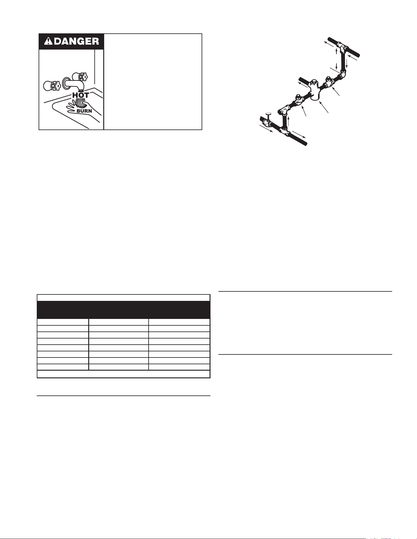
MIXING VALVES
Water heated to a temperature which will satisfy clothes
washing, dish washing, and other sanitizing needs can scald
and cause permanent injury upon contact. Short repeated
heating cycles caused by small hot water uses can cause
temperatures at the point of use to exceed the water heater’s
15
HOT WATER
OUTLET
TO TANK
INLET
CHECK
VALVE
MIXING
VALVE
COLD
WATER
INLET
TEMPERED WATER
OUTLET
12” TO 15”
(30-38 cm)
CHECK
VALVE
Figure 7. Mixing Valve
The National Sanitation Foundation also recommends
circulation of 180°F (82°C) water. The circulation should
be just enough to provide 180°F (82°C) water at the point
of take-off to the dish-washing machine.
Adjust ow by throttling a full-port ball valve installed in the
circulating line on the outlet side of the pump. Never throttle
ow on the suction side of a pump. See the Water Piping
Diagrams (page 66).
NOTE: To comply with NSF Standard 5 installation
requirements, the bottom of the water heater must be
sealed to the oor with a silicone based sealant or elevated
6 inches above the oor.
CLOSED WATER SYSTEMS
Water supply systems might have pressure reducing valves,
check valves, or back ow preventers installed to meet code
requirements or to adapt to such conditions as high line
pressure, among others. Devices such as these cause the
water system to be a closed system. If the water system is
closed, thermal expansion can occur.
THERMAL EXPANSION
As water is heated, it expands (thermal expansion).
In a closed system, as the volume of water grows, a
corresponding increase in water pressure occurs. The
increased pressure caused by the thermal expansion
can cause premature tank failure (leakage). This type of
failure is not covered under the limited warranty. Thermal
expansion can also cause intermittent water discharge from
the Temperature-Pressure Relief Valve: water discharged
from the valve due to excessive pressure build up. This
condition is not covered under the limited warranty. See
the Commercial Water Heater Limited Warranty provided
with this water heater.
The Temperature-Pressure Relief Valve is not intended for
the constant relief of thermal expansion.
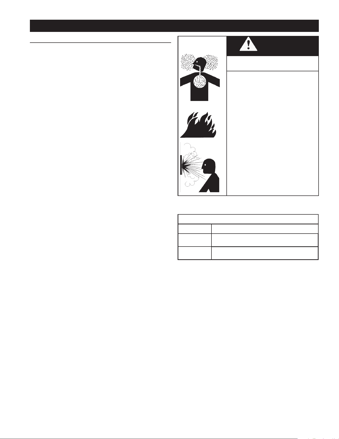
temperature setting by up to 20°F (11°C).
Water temperature over 125°F (52°C)
can cause severe burns instantly
resulting in severe injury or death.
Children, the elderly and the
physically or mentally disabled are at
highest risk for scald injury.
Feel water before bathing or
showering.
Temperature limiting devices such as
mixing valves must be installed
when required by codes and to
ensure safe temperatures at fixtures.
Some people are more likely to be permanently injured by
hot water than others. These include the elderly, children,
the inrm and the physically/mentally disabled. Table 5
shows the approximate time-to-burn relationship for normal
adult skin. If anyone using hot water provided by the water
heater being installed ts into one of these groups or if
there is a local code or state law requiring a certain water
temperature at the point of use, then special precautions
must be taken.
In addition to using the lowest possible temperature setting
that satises the demand of the application, a mixing valve
should be installed at the water heater or at the hot water
taps to further reduce system water temperature. See
Figure 7 (page 15).
Mixing valves are available at plumbing supply stores.
Consult a Qualied Installer or Service Agency. Follow
mixing valve manufacturer’s instructions for installation of
the valves.
Table 5. Burn Time At Various Temperatures
Water Temperature
°F (°C)
Time for 1st Degree Burn
(Less Severe Burns)
imeBurns
2nd & 3rd Degree
(Most Severe Burns)
110 (43) (normal shower temp.)
116 (47) (pain threshold)
116 (47) 35 minutes 45 minutes
122 (50) 1 minute 5 minutes
131 (55) 5 seconds 25 seconds
140 (60) 2 seconds 5 seconds
149 (65) 1 second 2 seconds
154 (68) instantaneous 1 second
(U.S. Government Memorandum, C.P.S.C., Peter L. Armstrong, Sept. 15, 1978)
DISH-WASHING MACHINES
All dish-washing machines meeting the National Sanitation
Foundation requirements are designed to operate with
water ow pressures between 15 and 25 pounds per square
inch (103 kPa and 173 kPa). Flow pressures above 25
pounds per square inch (173 kPa), or below 15 pounds per
square inch (103 kPa), will result in improperly sanitized
dishes. Where pressures are high, a water pressure
reducing or ow regulating control valve should be used
in the 180°F (82°C) line to the dish-washing machine and
should be adjusted to deliver water pressure between
these limits.
16
A thermal expansion tank provides a way to absorb excess
pressure caused by thermal expansion. A properly sized and
pressurized thermal expansion tank must be installed on
all closed systems to control the harmful effects of thermal
expansion. Contact a local plumbing service agency to have
a thermal expansion tank installed.
See Water Line Connections (page 44) and the Water
Piping Diagrams (page 66).
SAFETY VALVE REQUIREMENTS
The water heaters covered by this manual require the
following safety valves:
• A pressure-only relief valve between the water heating
unit outlet tting and the outlet tting at the top of the
storage tank
• A Temperature and Pressure Relief valve on the storage
tank in the customary position
WATER HEATING UNIT PRESSURE-ONLY RELIEF VALVE
The water heater has a high-temperature shutoff switch built
in as a standard safety feature (called a Hi-Limit switch)
therefore a “pressure only” relief valve is required.
This unit does not come with an approved pressure relief
valve, so this must be eld supplied.
An approved pressure relief valve must be installed on the
water heating unit hot water outlet. The pressure relief valve
must conform to ANSI Z21.22 or CAN 1-4.4 and installation
must follow local codes. The discharge capacity must be
at least 199,000 BTU/h. The pressure relief valve needs to
be rated for a maximum of 150 psi (1 MPa).
The discharge piping for the pressure relief valve must be
directed so that the hot water cannot splash outward and
cause damage or personal injury.
Attach the discharge tube to the pressure relief valve and
run the end of the tube to within 6 in (152 mm) from the oor.
This discharge tube must allow free and complete drainage
without any restrictions.
If the pressure relief valve discharges periodically, this
may be due to thermal expansion in a closed water supply
system. See Thermal Expansion (page 15) and/or
contact the water supplier or a local plumbing professional
on how to correct this situation.
Do not plug the pressure relief valve.
The pressure relief valve must be manually operated
periodically to check for correct operation. Before operating
the valve manually, check that it will discharge in a place
for secure disposal.
No valve must be placed between the relief valve and the
water heating unit.
TEMPERATURE-PRESSURE RELIEF VALVE
This water heater is provided with a properly rated/sized and
certied combination Temperature-Pressure Relief Valve
(T&P valve) by the manufacturer. The valve is certied by
a nationally recognized testing laboratory that maintains
periodic inspection of production of listed equipment of
materials as meeting the requirements for Relief Valves for
Hot Water Supply Systems, ANSI Z21.22 • CSA 4.4, and
the code requirements of ASME.
Explosion Hazard
Temperature-Pressure Relief Valve
must comply with ANSI Z21.22-
CSA 4.4 and ASME code.
Properly sized temperature-
pressure relief valve must be
installed in opening provided.
Can result in overheating and
excessive tank pressure.
Can cause serious injury or death.
If replaced, the new T&P valve must meet the requirements
of local codes, but not less than a combination Temperature-
Pressure Relief Valve rated/sized and certied as indicated
in the above paragraph. The new valve must be marked
with a maximum set pressure not to exceed the marked
hydrostatic working pressure of the water heater (150 psi
= 1,035 kPa) and a discharge capacity not less than the
water heater Btu/hr or kW input rate as shown on the water
heater’s model rating label.
NOTE: In addition to the factory installed Temperature-
Pressure Relief Valve on the water heater, each remote
storage tank that may be installed and piped to a water
heating appliance must also have its own properly sized,
rated and approved Temperature-Pressure Relief Valve
installed. Call the toll free technical support phone number
listed on the back cover of this manual for technical
assistance in sizing a Temperature-Pressure Relief Valve
for remote storage tanks.
For safe operation of the water heater, the Temperature-
Pressure Relief Valve must not be removed from its
designated opening nor plugged. The Temperature-
Pressure Relief Valve must be installed directly into the
tting of the water heater designed for the relief valve. Install
discharge piping so that any discharge will exit the pipe
within 6 inches (15.2 cm) above an adequate oor drain, or
external to the building. In cold climates, it is recommended
that it be terminated at an adequate drain inside the building.
Be certain that no contact is made with any live electrical
part. The discharge opening must not be blocked or reduced
in size under any circumstances. Excessive length, over 30
feet (9.14 m), or use of more than four elbows can cause
restriction and reduce the discharge capacity of the valve.
No valve or other obstruction is to be placed between the
Temperature-Pressure Relief Valve and the tank. Do not
17
follow the draining instructions in this manual, and replace
the Temperature-Pressure Relief Valve with a properly rated/
sized new one.
NOTE: The purpose of a Temperature-Pressure Relief Valve
is to prevent excessive temperatures and pressures in the
storage tank. The T&P valve is not intended for the constant
relief of thermal expansion. A properly sized thermal
expansion tank must be installed on all closed systems to
control thermal expansion, see Thermal Expansion and
Closed Water Systems (page 15).
If you do not understand these instructions or have any
questions regarding the Temperature-Pressure Relief Valve,
call the toll free number listed on the back cover of this
manual for technical assistance.
CONDENSATE DRAIN
The water heaters covered in this manual require a drain
near the water heater to allow the condensate to drain
safely. The condensate accumulates as a by-product of
combustion. Condensate drains from the water heating
unit through a drain tube to the drain. The condensate drain
tube must leave an air gap of two inches and must not be
elevated above the condensate drain connection.
If the condensate does not drain properly, it will build up in
the water heating unit and interfere with its function.
CONDENSATE PH LEVEL
The condensate that drains from the water heater’s covered
in this manual have pH levels between 4.3 and 5.0. Install
a commercially available neutralizing kit if required by local
codes.
NOTE: Lower pH levels are acidic. Do not connect a
metal drain line, such as copper, to the water heater for
this reason. See Water Heating Unit Condensate Drain
(page 37).
COMBUSTIBLE MATERIAL STORAGE
Remove any combustible materials, gasoline or any
ammable vapors and liquids.
connect discharge piping directly to the drain unless a 6”
(15.2 cm) air gap is provided. To prevent bodily injury, hazard
to life, or property damage, the relief valve must be allowed
to discharge water in adequate quantities if circumstances
demand. If the discharge pipe is not connected to a drain
or other suitable means, the water ow may cause property
damage.
Water Damage Hazard
Temperature-Pressure Relief Valve discharge
pipe must terminate at adequate drain.
•
CAUTION
T&P VALVE DISCHARGE PIPE REQUIREMENTS
• Shall not be smaller in size than the outlet pipe size
of the valve, or have any reducing couplings or other
restrictions.
• Shall not be plugged or blocked.
• Shall not be exposed to freezing temperatures.
• Shall be of material listed for hot water distribution.
• Shall be installed so as to allow complete drainage of
both the Temperature-Pressure Relief Valve and the
discharge pipe.
• Must terminate a maximum of six inches above a oor
drain or external to the building. In cold climates, it is
recommended that the discharge pipe be terminated at
an adequate drain inside the building.
• Shall not have any valve or other obstruction between
the relief valve and the drain.
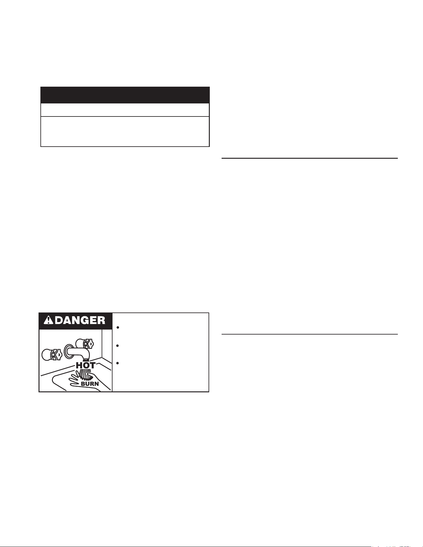
Burn hazard.
Hot water discharge.
Keep clear of Temperature-
Pressure Relief Valve
discharge outlet.
The Temperature-Pressure Relief Valve must be manually
operated at least twice a year. Caution should be taken
to ensure that (1) no one is in front of or around the outlet
of the Temperature-Pressure Relief Valve discharge line,
and (2) the water manually discharged will not cause any
bodily injury or property damage because the water may
be extremely hot. If after manually operating the valve, it
fails to completely reset and continues to release water,
immediately close the cold water inlet to the water heater,
18
Fire or Explosion Hazard
Read instruction manual before
installing, using or servicing
water heater.
Avoid all ignition sources if you smell gas.
Do not store or use gasoline or other flammable vapors and
liquids in the vicinity of this or any other appliance.
Use only the gas shown on the water heater rating label.
Keep ignition sources away from faucets after extended
periods of non-use.
Maintain required clearances to combustibles.
Do not expose water heater controls to excessive gas
pressure.
Keep water heater area clear and free of combustible
materials, gasoline, and other ammable vapors and liquids.
VENTILATION REQUIREMENTS
COMBUSTION AIR SUPPLY
Before installing the water heater, you must determine the
amount of air needed to supply this water heater and any
other gas appliances in the same area and provide adequate
air for combustion and ventilation. Consult a qualied
person if you’re unsure of the proper way to supply air to
your water heater.
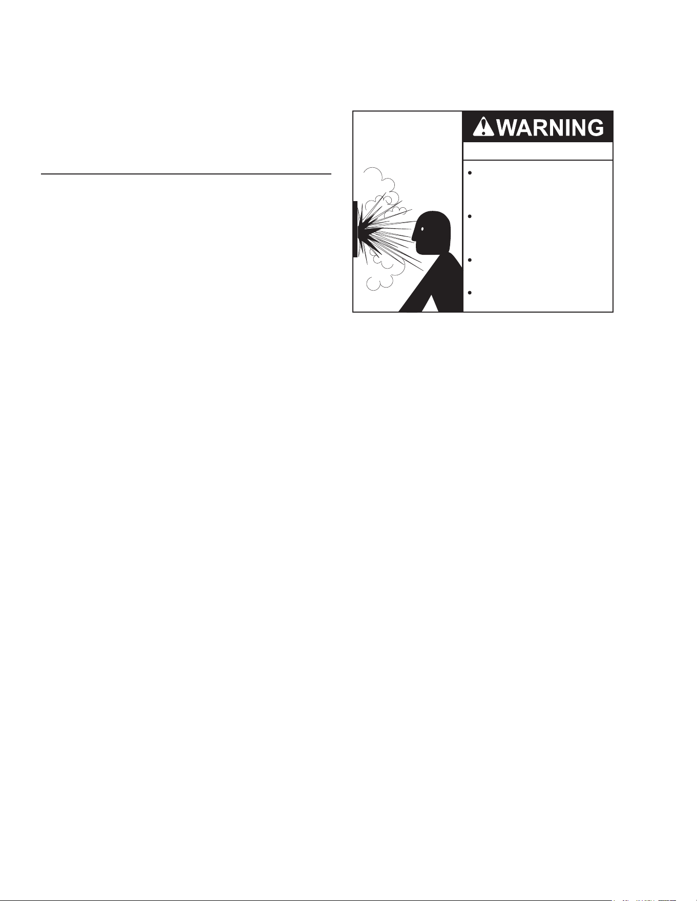
WARNING
Breathing Hazard
This gas water heater requires an adequate
source of clean air for combustion and
ventilation. Without sufcient air, your water
heater may not operate properly and may emit
excessive and abnormal amounts of carbon
monoxide which may result in carbon monox-
ide poisoning or death.
Breathing carbon monoxide can cause brain damage
or death. Always read and understand the instruction
manual.
The guidelines in this section apply to installations within
the United States. All U.S. installations must conform to the
National Fuel Gas Code, ANSI Z223.1/NFPA 54 (current
edition) and local codes.
Canadian requirements differ from the guidelines in this
section. In Canada, follow the requirements of B149.1
(Natural Gas and Propane Installation Code, current
edition) as well as local and provincial codes. Contact your
local code enforcement agency for direction.
Check for Chemicals
Air for combustion and ventilation must be clean and free
of corrosive chemicals. If corrosive chemicals, such as
sulfur, ourine, or chlorine are present, the water heater
must be direct vented. Failure of the water heater due to
these corrosive chemicals is not covered by the warranty.
WARNING!: In all cases, ensure that corrosive chemicals
are not present at the air intake. Presence of such chemicals
at the air intake could result in death, personal injury, or
property damage. Examples of locations that require outside
air due to chemicals include:
• Beauty salons
• Photo processing labs
• Indoor pools
• Laundry, hobby, or craft rooms
• Chemical storage areas
Products such as aerosol sprays, detergents, bleaches,
cleaning solvents, gasoline, air fresheners, paint and
varnish removers, and refrigerants should not be stored or
used near the water heater.
Does your installation space have sufcient combustion air?
Ventilation with outside air is recommended for all
installations. Even if the water heater is installed in a large,
open room inside the house, outdoor air is usually needed
because modern homes are very tightly sealed and often
do not supply enough air to the water heater. However,
when installed in a large indoor space, it may be possible
to provide enough air without outside ventilation. If you are
unsure if your installation location has enough ventilation,
contact your local gas utility company or code ofcials for
a safety inspection or direct vent the water heater
The following instructions will help determine if it may
be possible to install the water heater without outside
ventilation.
Calculate Total BTU/h Rating of All Appliances
To calculate the combustion air and ventilation required, add
up the total BTU/h ratings of all gas burning appliances (e.g.,
water heaters, furnaces, clothes dryers) in the same area.
Do not include appliances that are direct vented. Refer to
the following example.
Your water heater’s BTU/h rating is on the rating plate.
The BTU/h ratings should be on the other appliances’
rating plates. If you have trouble determining the BTU/h
ratings, contact the manufacturer or have a qualied person
determine the ventilation requirements.
NOTICE: If you are replacing your old water heater with one
that has a higher BTU/h rating, the amount of ventilation
required may be greater.
19
Example:
Gas Burning Appliance BTU/h Rang
Gas Water Heater 199,000
Furnace 75,000
Dryer 20,000
Total 294,000
Worksheet for Your Appliances:
Gas Burning Appliance BTU/h Rang
Gas Water Heater
Total
Calculate the Air Volume of the Room
Air requirements depend on the size of the room.
Room Volume (ft
3
) = Floor Area (ft
2
) X Ceiling Height (ft)
If there are large objects in the room (e.g., refrigerator,
furnace, car), subtract their volume from the volume of the
room to get a better estimate of the air available.
Air Volume = Room Volume - Object Volume
NOTE: Adjoining rooms with permanently opened doorways
can be counted as part of the calculation.
Calculate Required Air Volume
A water heater installed in an unconned attic, garage, or
space requires that the space be at least 50 ft
3
(1.42 m
3
) per
1,000 BTU/h of the total input for all gas burning appliances
in the same area.
Required Air Volume (ft
3
) =Total Appliance Energy
Rating (btu/h) X 50 ft
3
/ 1000 (btu/h)
Example:
(294,000 / 1000) x 50 = 14,700 ft
3
If the air volume of the room is less than the required air
volume, you must direct vent the water heater or provide
permanent outside air openings that draw in sufcient air.
See Install with Outside Ventilation (page 19) if you
want to provide combustion air with outside ventilation.
If the air volume of the room is greater than the required
air volume, it may be possible to install the water heater
without outside ventilation. However, be sure to consider
the effects of exhaust fans.
Exhaust fans can affect the amount of combustion air that
is available in your home. Appliances such as furnaces,
whole house fans, and clothes dryers draw air out of your
home. If they draw air out faster than it can be replaced, your
water heater may not have enough oxygen to re properly.
Back-drafting may also result, which is when negative air
pressure pulls air backwards through chimneys or appliance
vents. These events can cause unsatisfactory water heater
performance. The best solution is to direct vent the water
heater or install an adequate number of make-up air vents.
See Install with Outside Ventilation (page 19). For
more information, consult a qualied technician or your
local gas utility.
Install with Outside Ventilation
Ventilation with outside air is recommended, and, for most
installations, is needed. There may be existing ventilation
that is adequate, or you may need to add more ventilation.
Supplying outside air to the water heater typically requires
two openings. One opening must be within 12 in (305 mm)
from the oor and the second opening must be within 12
in (305 mm) from the ceiling. Although a single opening
is not preferred, you may use a single opening to outside
air if the minimum free area is sized according to Table 6.
Two openings must be used when ventilating with air from
another room.
The outside air can be taken from a crawl space or attic
open to the outdoors and adequately ventilated. You may
use vertical or horizontal ducts.
Determine Type of Ventilation
There are several types of ventilation that can be used. The
following are the various ventilation options.
1. Direct to outdoors
2. Vertical ducts
3. Horizontal ducts
4. Single opening (not recommended; must be at least
100 in
2
(6.5 cm
2
) . Not appropriate for conned spaces
smaller than 50 ft
3
(1.42 m
3
) per 1,000 BTU/h or when
getting air from another room.)
5. From a larger room inside the house (not recommended
– refer to "Calculate the air volume of the room" above
to determine if the combined volume of the rooms may
be adequate).
See also the illustrations on the next page.
Determine Minimum Free Area Required for Each Vent Opening
The size of the vent openings depends on the total BTU/h
rating of all appliances in the space (use your calculation
from “Before beginning”) and the type of vent used. Table
6 provides the minimum free area for each vent opening
depending on the type of ventilation.
Calculate Minimum Size of Vent Openings and Ducts
The vent cross-sectional area needed to provide the free
area depends on the covering on the vent openings. Typical
vents use louvers or grilles to protect the opening. The
louver or grill itself blocks some of the free area, so the
opening may need to be larger to meet the minimum free
area requirements.
20
Use the following formula to calculate the required cross-
sectional area:
Cross-sectional area = minimum free area required ÷
percent free area of covering (in decimals – e.g., 60 % = 0.6)
For example, an installation area that requires openings
with 100 in
2
(645 cm
2
) of free area would need 134 in
2
(865
cm
2
) openings if using metal louvers rated at 75% free area
(100 in
2
÷ 0.75 = 134 in
2
).
If you do not know the % free area for your louver or grill,
use the following values:
• For wood louvers or grilles: 25%
• For metal louvers or grilles: 75%
Follow these rules to ensure that vents and ducts provide
adequate air ow:
• Each vent opening must be no smaller than 100 in
2
(645 cm
2
).
• Ducts must have the same cross-sectional area as free
area of the opening.
• Rectangular ducts must have a minimum dimension of
no less than 3 in (76 mm).
• All screens must have mesh ¼” or larger.
• Moveable louvers must be locked open or interconnected
with the equipment so that they open automatically
during operation.
• Keep louvers and grills clean and free of debris or other
obstructions.
Check that Air Source is Clean and Free of Chemicals
Air for combustion and ventilation must be clean and
free of corrosive or ammable chemicals. A failure due to
corrosive chemicals in the air is not covered by the warranty.
Combustion air must be free of acid-forming chemicals such
as sulfur, uorine, and chlorine. Be sure that air at the vent
inlets is free of such chemicals.
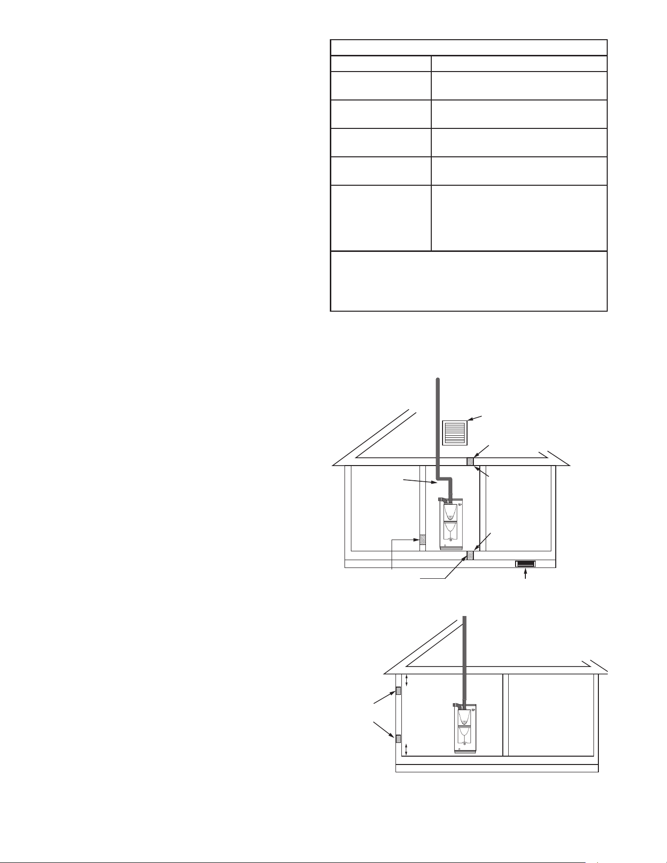
Table 6 shows the minimum free area of permanent
openings for ventilation and combustion air supply with air
from outdoor or indoor spaces. The values are based on
the total BTU/h input rating for all gas burning appliances
within a conned space.
Table 6. Minimum Free Area by Ventilation Type
Opening Source Minimum Free Area
Direct to outdoors*
1 in
2
(6.5 cm
2
) per 4,000 BTU/hr (See
Figure 8 and Figure 9.)
Vertical ducts
1 in
2
(6.5 cm
2
) per 4,000 BTU/hr (See
Figure 13.)
Horizontal ducts
1 in
2
(6.5 cm
2
) per 2,000 BTU/hr (See
Figure 10.)
Single Opening
1 in
2
(6.5 cm
2
) per 3,000 BTU/hr (See
Figure 11.)
Two permanent
openings
to another room**
1 in
2
(6.5 cm
2
) per 1,000 Btu/hr (See
Figure 12.)
Opening: 100 in
2
(645 cm
2
) MIn
Minimum dimension of air openings:
no less than 3 in (76 mm)
*These openings connect directly with the outdoors through a ventilated attic, a
ventilated crawl space, or through an outside wall.
**United States: For direction on combining spaces in different stories within
the structure, refer to the current edition of the National Fuel Gas Code ANSI
Z223.1/NFPA 54. In Canada, contact your local code enforcement agency for
direction.
Combustion Air Supply Options
Figure 8 through Figure 12 illustrate the range of methods
available for ensuring adequate combustion air for the
water heater.
Gable vent
to outdoors
Install above
insulaon
Outlet air to
ac 1 in
2
(6.5 cm
2
)
per 4,000 btu/h
Inlet air from
the crawl space
Open foundaon vent
Confined
Space
Alternate
Air Inlet
1 in
2
(6.5 cm
2
)
per 4,000 btu/h
Figure 8. Air from Outdoors Openings
Two permanent
Openings
1 in
2
(6.5 cm
2
)
per 4,000 btu/h
12” (305 mm)
maximum
Confined
Space
12” (305 mm)
maximum
Figure 9. Outdoor Air Through Two Openings
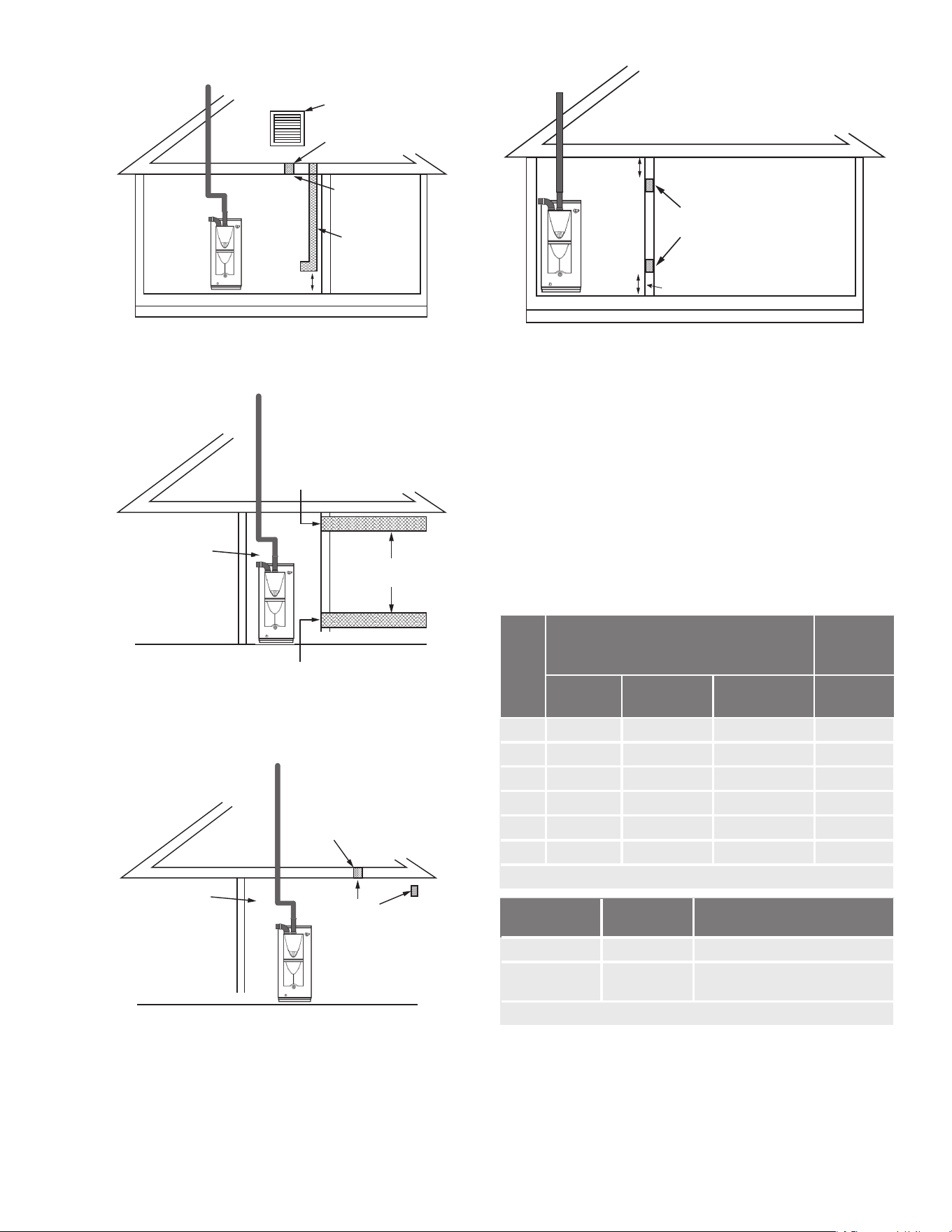
21
Outlet air to
ac 1 in
2
(6.5 cm
2
)
per 4,000 btu/h
Inlet air duct
1 in
2
(6.5 cm
2
)
per 4,000 btu/h
Confined
Space
12” (305 mm)
maximum
Gable vent
to outdoors
Install above
insulaon
Figure 10. Vertical Duct Openings
1 in
2
(6.5 cm
2
)
per 2,000 btu/h
Confined
Space
Outlet
Inlet
Outdoor
Air Ducts
1 in
2
(6.5 cm
2
)
per 2,000 btu/h
Figure 11. Horizontal Duct Openings
Confined
Space
1 in
2
(6.5 cm
2
)
per 3,000 btu/h
Alternave
Opening
Locaon
Figure 12. Outdoor Air Through One Opening
Two permanent
Openings
1 in
2
per
1,000 btu/h
12” (305 mm)
maximum
Confined
Space
12” (305 mm) maximum
Figure 13. Indoor Air Through Two Permanent Openings
MAXIMUM EQUIVALENT PIPE LENGTHS AND ELBOWS
The maximum length of exhaust vent piping must not
exceed 70 ft (21.3 m) for 3” venting, which depends on
the elevation where the water heater is installed, and 100
ft (30.5 m) for 4” venting (deducting 5 ft (1.5 m) for each
elbow used in the venting system). Do not use more than
5 elbows. See Table 7.
When the horizontal vent run exceeds 5 ft (1.5 m), support
the vent run at 3 ft (0.9 m) intervals with overhead hangers.
Table 7. Equivalent Lengths and Maximum Number of Elbows
No. of
Elbows
3" (76 mm) Venting
4" (102 mm)
Venting
0 to 3,000 ft
(0 to 914 m)
3,001 to 6,000 ft
(915 to 1,829 m)
6,001 to 10,100 ft
(1,830 to 3,078 m)
0 to 10,100 ft
(0 to 3,078 m)
0 70 ft (21.3 m) 40 ft (12.2 m) 25 ft (7.6 m) 100 ft (30.5 m)
1 65 ft (19.8 m) 35 ft (10.7 m) 20 ft (6.1 m) 95 ft (29.0 m)
2 60 ft (18.3 m) 30 ft (9.1 m) 15 ft (4.6 m) 90 ft (27.4 m)
3 55 ft (16.8 m) 25 ft (7.6 m) 10 ft (3.0 m) 85 ft (25.9 m)
4 50 ft (15.2 m) 20 ft (6.1 m) N/A 80 ft (24.4 m)
5 45 ft (13.7 m) N/A N/A 75 ft (22.9 m)
Excludes vent terminators, termination elbows, or rain caps.
Diameter
Max. No. of
Elbows
Max. Vertical and Horizontal
(Total) Vent Length
3 in. (76 mm)
5 70 ft (21.3 m)
4 in. (102
mm)
5 100 ft (30.5 m)
*For each elbow added, deduct 5 ft. (1.5 m) from max. vent length.
22
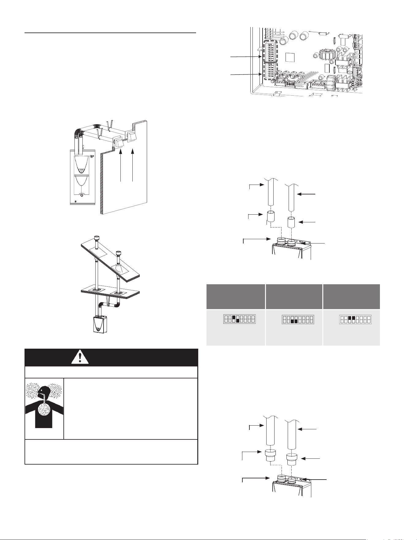
Upper DIP
Switch
Bank
Lower DIP
Switch Bank
Figure 16. Location of DIP Switches
Installing a Three-Inch (76 mm) Direct Vent Connection
1. Connect 3" (76 mm) couplings directly on the exhaust
and intake vent collar of the water heater.
2. Connect 3" (76 mm) straight pipes to the couplings.
3. Locate lower bank of DIP switches and set the
appropriate switches for this conguration. See the
appropriate settings below.
3"(76 mm)
s
traight pipe
3" (76 mm) coupling
(included)
I
ntake vent collar
(Female)
3" (76 mm)
straight pipe
3" (76 mm) coupling
(included)
Exhaust vent collar
(Female)
Figure 17. 3" (76 mm) Vent Connection
Table 8. DIP Switch Settings: Three-Inch Direct Vent
5 to 20 ft
(1.5 to 6.1m)
(DEFAULT)
21 to 40 ft
(6.2 to 12.2 m)
41 to 70 ft
(12.3 to 21.3 m)
OFF
ON
1 2 3 4 5 6 7 8
No. 3 : O N
No. 4 : OFF
OFF
ON
1 2 3 4 5 6 7 8
No. 3 : OFF
No. 4 : OFF
OFF
ON
1 2 3 4 5 6 7 8
No. 3 : O N
No. 4 : O N
Installing a Four-Inch (102 mm) Direct Vent Connection
1. Connect 3"x 4" (76 x 102 mm) adaptors directly on the
exhaust and intake vent collar of the water heater.
2. Connect 4" (102 mm) straight pipes to the adaptors.
3. Locate lower bank of DIP switches and set the
appropriate switches for this conguration. See the
appropriate settings below.
4" (102 mm)
s
traight pipe
3"x 4"
(76 x 102 mm)
adaptor
I
ntake vent collar
(Female)
4" (102 mm)
straight pipe
3"x 4"
(76 x 102 mm)
adaptor
Exhaust vent collar
(Female)
Figure 18. Four-Inch (102 mm) Two-Pipe Vent Connection
DIRECT VENT INSTALLATIONS
TWO-PIPE, DIRECT-VENT INSTALLATION
For details of the optional items, refer to the Installation
manual for each optional item.
HOW TO INSTALL A TWO-PIPE, DIRECT-VENT SYSTEM
Install as shown in the following gures. See Clearances
For Rooftop Terminations (page 36) for the proper
clearances.
Wall
Hanger
Hanger
Sidewall Vent
Terminations
Figure 14. Two-Pipe Horizontal Installation
Figure 15. Two-Pipe Vertical Installation
WARNING
Breathing Hazard
• Adjust the appropriate DIP switches according to
model and vent length as shown. DO NOT adjust
the other DIP switches.
• Turn off the power supply to the water heater
before changing the DIP switch settings.
• Failure to observe these warnings could lead to
carbon monoxide poisoning or death.
Breathing carbon monoxide can cause brain damage
or death. Always read and understand the instruction
manual.
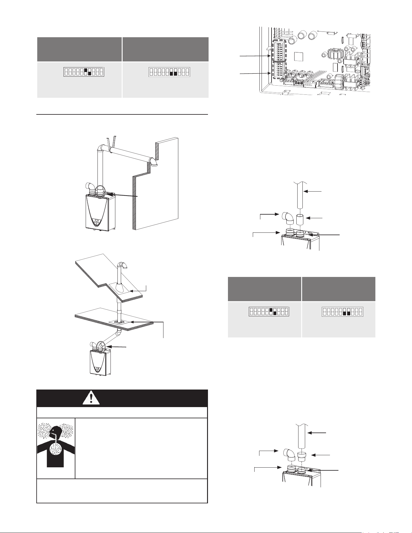
23
Upper DIP
Switch
Bank
Lower DIP
Switch Bank
Figure 21. Location of DIP Switches
How to Install a Three-Inch Single-Vent Installation
1. Connect a 3" (76 mm) elbow directly on the intake vent
collar of the water heater.
2. Connect a 3" (76 mm) coupling directly on the exhaust
vent collar of the water heater.
3. Connect a 3" (76 mm) straight pipe to the coupling.
4. Locate lower bank of DIP switches and set the
appropriate switches for this conguration. See the
appropriate settings below.
3” (76 mm) elb
ow
with bi
rd screen
I
ntake vent collar
(Female)
3"(76 mm)
straight pipe
3" (76 mm) coupling
(included)
Exhaust vent
collar
(Female)
Figure 22. Three-Inch (76 mm) Vent Connection
Table 10. DIP Switch Settings: Three-Inch Single-
Vent Pipe
5 to 45
(1.5 to 13.7m)
(DEFAULT)
46 to70
(13.8 to 21.3 m)
OFF
ON
1 2 3 4 5 6 7 8 9 10
No. 6 : O N
No. 7 : OFF
OFF
ON
1 2 3 4 5 6 7 8 9 10
No. 6 : OFF
No. 7 : OFF
How to Install a Four-Inch Single-Vent Installation
1. Connect a 3" (76 mm) elbow directly on the intake vent
collar of the water heater.
2. Connect a 3" x 4" (76 x 102 mm) adaptor directly on the
exhaust vent collar of the water heater.
3. Connect a 4" (102 mm) straight pipe to the adaptor.
4. Locate lower bank of DIP switches and set the
appropriate switches for this conguration. See the
appropriate settings below.
3” (76 mm) elb
ow
with bi
rd screen
I
ntake vent collar
(Female)
4" (102 mm)
straight pipe
3"x 4"
(76 x 102 mm)
increaser
Exhaust vent
collar
(Female)
Figure 23. Four-Inch (102 mm) Vent Connection
Table 9. DIP Switch Settings: Four-Inch Direct Vent
5 to 50 ft
(1.5 to 15.2m)
(DEFAULT)
51 to 100 ft
(15.3 to 30.5 m)
OFF
ON
1 2 3 4 5 6 7 8 9 10
No. 6 : O N
No. 7 : OFF
OFF
ON
1 2 3 4 5 6 7 8 9 10
No. 6 : OFF
No. 7 : OFF
SINGLE-VENT INSTALLATIONS
HOW TO INSTALL A SINGLE-PIPE WITH ROOM-AIR INTAKE INSTALLATION
Elb
ow
Hanger
Wall
Connect between
exhaust vent
collar and piping.
Figure 19. Single-Pipe Horizontal Installation
Roof
Roof Flashing
Fire Stop
Elbow
Connect between
exhaust vent collar
and piping.
Figure 20. Single-Pipe Vertical Installation
WARNING
Breathing Hazard
• Adjust the appropriate DIP switches according to
model and vent length as shown below. DO NOT
adjust the other DIP switches.
• Turn off the power supply to the water heater before
changing the DIP switch settings.
• Failure to observe these warnings could lead to
carbon monoxide poisoning or death.
Breathing carbon monoxide can cause brain damage
or death. Always read and understand the instruction
manual.
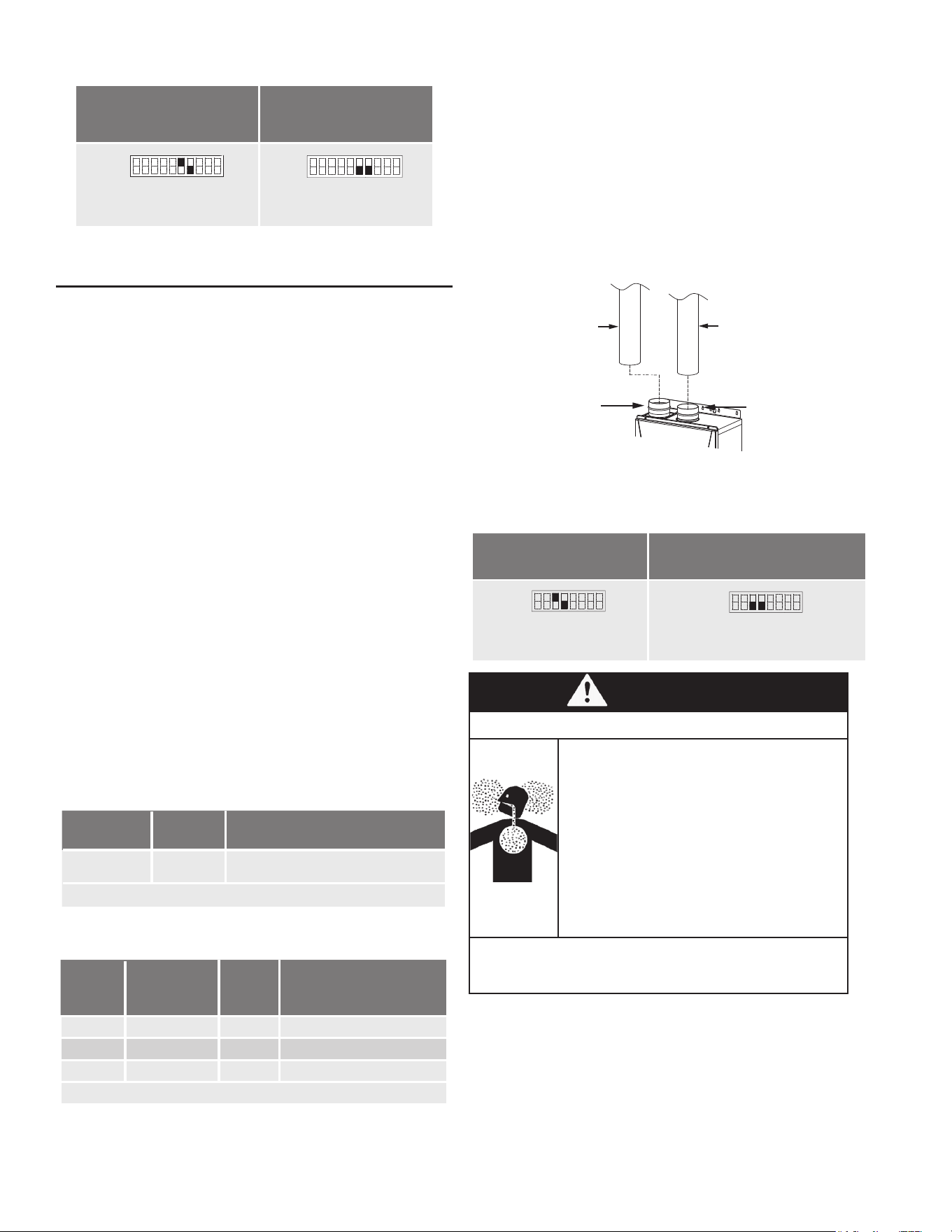
24
Table 11. DIP Switch Settings: Four-Inch Single-Vent Pipe
5 to 50 ft
(1.5 to 15.2m)
(DEFAULT)
51 to 100 ft
(15.3 to 30.5 m)
OFF
ON
1 2 3 4 5 6 7 8 9 10
No. 6 : O N
No. 7 : OFF
OFF
ON
1 2 3 4 5 6 7 8 9 10
No. 6 : OFF
No. 7 : OFF
STAINLESS STEEL VENT INSTALLATIONS
This is a Category IV appliance and must be vented
accordingly. The vent system must be sealed airtight. All
seams and joints without gaskets must be sealed with
high heat resistant silicone sealant or UL listed aluminum
adhesive tape having a minimum temperature rating of 160
°F (71 °C). For best results, a vent system should be as
short and straight as possible.
• This water heater is a Category IV appliance and must
be vented accordingly with any 4” vent approved for use
with Category III/IV or Special BH type gas vent.
• The manufacturer recommends the NovaVent line.
However, the following are also UL listed manufacturers:
ProTech Systems Inc. (FasNSeal), Metal-Fab Inc., and
Heat-Fab Inc. (Saf-T Vent).
• Follow the vent pipe manufacturer’s instructions when
installing the vent pipe.
• The maximum length of exhaust vent piping must not
exceed 100 ft (30.5 m) (deducting 5 ft (1.5 m) for each
elbow used in the venting system). Do not use more
than 5 elbows.
• When the horizontal vent run exceeds 5 ft (1.5 m),
support the vent run at 3 ft (0.9 m) intervals with overhead
hangers.
STAINLESS STEEL ELBOW/LENGTH REQUIREMENTS
Table 12. Maximum Elbows for Vent Length
Diameter
Max. No.
of Elbows
Max. Vertical and Horizontal
(Total) Vent Length*
4 in.
(102 mm)
5 100 ft (30.5 m )
*For each elbow added, deduct 5 ft. (1.5 m) from max. vent length
Table 13. Maximum Length Per Number of Elbows
No. of
Elbows
Max. Vertical
or Horizontal
Vent Length
No. of
Elbows
Max. Vertical or
Horizontal Vent Length
0 100 ft (30.5 m) 3 85 ft (25.9 m)
1 95 ft (29.0 m) 4 80 ft (24.4 m)
2 90 ft (27.4 m) 5 75 ft (22.9 m)
Excludes vent terminators, termination elbows, or rain caps.
HOW TO INSTALL A STAINLESS STEEL DIRECT VENT
The following are typical installations using stainless steel
vents:
Installing a Four-Inch Stainless-Steel Direct Vent Connection
1. Connect 4" (102 mm) stainless steel vent straight pipes
directly on the exhaust/intake vent collar of the water
heater.
2. Locate lower bank of DIP switches and set the
appropriate switches for this conguration. See the
appropriate settings below.
4" (102 mm)
stainless steel vent
straight pipe
4" (102 mm)
stainless steel vent
straight pipe
Intake vent collar
(Female)
Exhaust vent
collar of the
Indoor models
Figure 24. Four-Inch Stainless Steel Direct Vent Connection
Table 14. DIP Switch Settings for Two-Pipe Direct Vent Installations
5 to 50 ft
(1.5 to 15.2m)
(DEFAULT)
51 to 100 ft
(15.3 to 30.5 m)
OFF
ON
1 2 3 4 5 6 7 8
No. 3 : O N
No. 4 : OFF
OFF
ON
1 2 3 4 5 6 7 8
No. 3 : OFF
No. 4 : OFF
WARNING
Breathing Hazard
• Adjust the appropriate DIP switches according
to model and vent length as shown below. DO
NOT adjust the other DIP switches.
• Turn off the power supply to the water heater
before changing the DIP switch settings.
• Failure to observe these warnings could lead to
carbon monoxide poisoning or death.
Breathing carbon monoxide can cause brain damage
or death. Always read and understand the instruction
manual.
Installing a Stainless-Steel Single Vent Connection
1. Connect a 4" (102 mm) stainless steel vent straight pipe
directly on the exhaust vent collar of the water heater.
2. Connect a 4" (102 mm) elbow directly on the intake vent
collar of the water heater.
3. Locate lower bank of DIP switches and set the
appropriate switches for this conguration. See the
appropriate settings below.
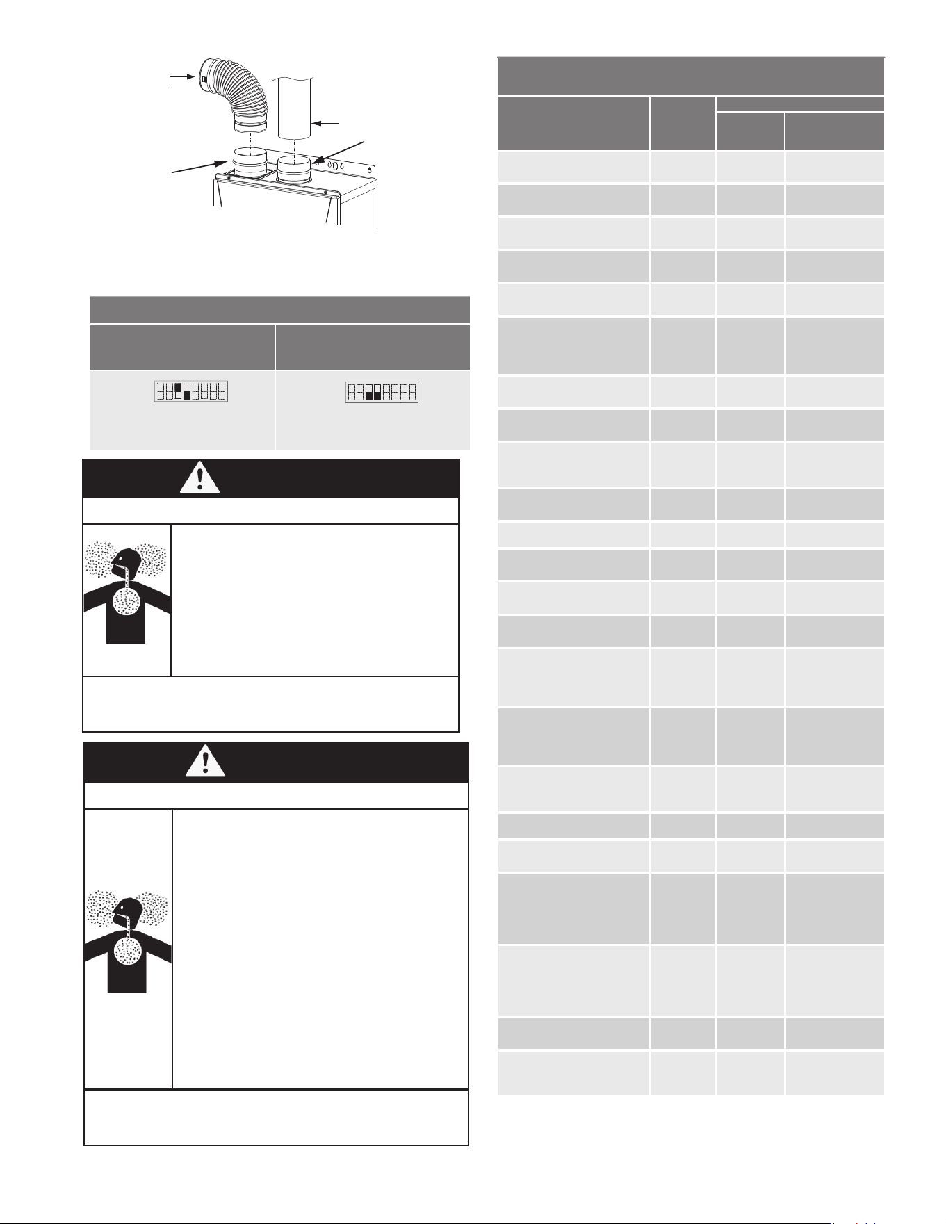
25
Approved Category IV, Single Wall, Venting Suppliers
and Part Numbers
Description
Heater
Vent Kits
Z-FLEX®
Nova
VENT™
Z-VENT™
4" (102 mm) Straight pipe
- 6" (152 mm) length
100112407 2NVP4.5 2SVEPWCF0406
4" (102 mm) Straight pipe
- 12" (305 mm) length
100112406 2NVP41 2SVEPWCF0401
4" (102 mm) Straight pipe
- 24" (610 mm) length
100112404 2NVP42 2SVEPWCF0402
4" (102 mm) Straight pipe
- 36" (914 mm) length
100112403 2NVP43 2SVEPWCF0403
4" (102 mm)Straight pipe
- 48" (1,219 mm) length
100112402 2NVP44 2SVEPWCF0404
4" (102 mm) Adjustable
straight pipe -
10"-18" (254 - 457 mm)
adjustability
100112405 2NVAL4 2SVSPA04
4" (102 mm) 45 degree
elbow
100112401 2NVE445 2SVEEWCF0445
4" (102 mm) 90 degree
elbow
100112400 2NVE490 2SVEEWCF0490
4" (102 mm) Sidewall
termination (4" (102 mm)
Termination Hood)
100112419 2NVTH4 2SVSHTX04
4" (102 mm) Vent
termination tee
100112547 2NVTT4 2SVSTTF04
4" (102 mm) Rain Cap 100112415 2NVRC4 2SVSRCF04
4" (102 mm) Extreme
weather rain cap
100112548 2NVWC4 2SVSHRC04
4" (102 mm) Horizontal
drain tee
100112414 2NVHD4 2SVEDWCF04
4" (102 mm) Vertical drain
tee
100112413 2NVVD4 2SVEVDP04
4" (102 mm) wall thimble
length
4"-7" (102 - 178 mm)
wall thickness
100112732 2NVWT4 2SVSWTF04
4" (102 mm) wall thimble
length
5"-10" (127 - 254 mm)
wall thickness
100112733 2NVWT4L 2SVSWTEF04
4" (102 mm) 3-in-1 adaptor
(F-F adaptor, condensate
drain, & back-ow preventer)
100112585 2NVBFA4 2SVBFDPA04
4" (102 mm) F-F adaptor 100112399 2NVAFF4 2SVEEWCF0445
4" (102 mm) Backow pre-
venter w/ F-F adaptor
100112416 2NVBFU4 2ZVB04
4" (102 mm) exhaust / 3" (76
mm) intake DV concentric
termination
- 5"-10" (127 - 254 mm)
adjustability
100112550 2NVHTC43S 2SVSHTC43S
4" (102 mm)exhaust / 3" (76
mm) intake DV concentric
termination
- 12"-18" (305 - 457 mm)
adjustability
100112551 2NVHTC43 2SVSHTC43
4" (102 mm) Sidewall termi-
nation, adjustable pipe
100187853 2NVBV4 n/a
4" (102 mm) Wall Thimble,
3"-6"(76 - 152 mm) wall
thickness
100187852 2NVBT4 n/a
4" (102 mm) elb
o
w
with bi
rd screen
4” (102 mm)
stainless steel vent
straight pipe
Exhaust vent collar
(Female)
Intake vent
collar (Female)
Figure 25. 4"Vent Connection for Single Vent Installation
Table 15. DIP switch settings : Single Pipe Direct Vent installations
4" (102 mm) Venting
5 to 50 ft
(1.5 to 15.2m)
(DEFAULT)
51 to 100 ft
(15.3 to 30.5 m)
OFF
ON
1 2 3 4 5 6 7 8
No. 3 : O N
No. 4 : OFF
OFF
ON
1 2 3 4 5 6 7 8
No. 3 : OFF
No. 4 : OFF
WARNING
Breathing Hazard
• Adjust the appropriate DIP switches according
to model and vent length as shown below. DO
NOT adjust the other DIP switches.
• Turn off the power supply to the water heater
before changing the DIP switch settings.
• Failure to observe these warnings could lead to
carbon monoxide poisoning or death.
Breathing carbon monoxide can cause brain damage
or death. Always read and understand the instruction
manual.
WARNING
Breathing Hazard
• Regarding the clearances from the exhaust
terminal to the air inlet or opening, See
Termination Clearances for Sidewall
Installations (page 34) and Clearances
For Rooftop Terminations(page 36).
• Follow all vent system manufacturer’s instructions
and all local codes.
• Use 4" (102 mm) Category III/IV approved or
Special BH, single or double wall stainless steel
vent pipe.
• Do not mix parts or ttings of different material
types, and do not mix pipe, ttings, or joining
methods from different manufacturers.
Combustion exhaust can contain carbon
monoxide and must be properly vented outside.
Breathing abnormal amounts of carbon monoxide
can result in serious injury or death.
Breathing carbon monoxide can cause brain damage
or death. Always read and understand the instruction
manual.
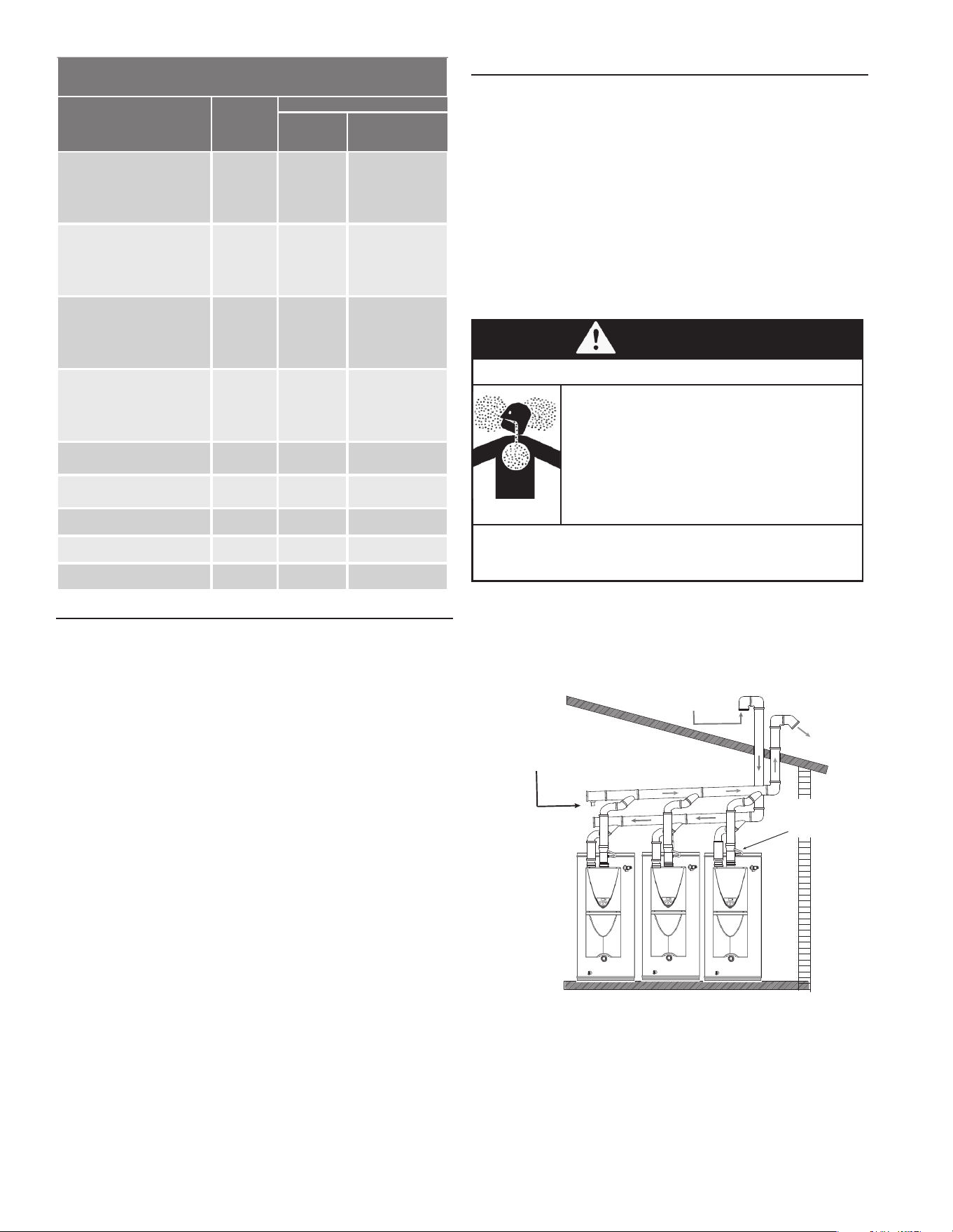
26
COMMON DIRECT-VENTING SYSTEM
The water heater can be vented together with other water
heaters using the same exhaust and intake venting.
Up to 8 water heaters can be common-vented together.
A non-return valve (100113130) must be used for each
water heater that is part of the system.
The water heaters must all be direct-vented.
The common-venting system shall be in accordance with
the National Fuel Gas Code, ANSI Z223.1/NFPA 54
and/or B149.1, Natural Gas and Propane Installation
Code (Current Editions), local codes, and the following
manufacturer’s instructions.
WARNING
Breathing Hazard
Only the (A/S/M) TX-199 models can
be common-vented together. Different
models cannot be common-vented.
Failure to observe these warnings could
lead to carbon monoxide poisoning or
death.
Breathing carbon monoxide can cause brain damage
or death. Always read and understand the instruction
manual.
TYPICAL COMMON VENT SYSTEM CONFIGURATIONS
For common-venting pieces and components, the
manufacturer recommends Centrotherm's vent line. The
following are some typical common vent congurations:
Intake
Exhaust
Condensate Drain Port
Non Return
Valve
Figure 26. Common Vent, Vertical Intake, Vertical Vent
Approved Category IV, Single Wall, Venting Suppliers
and Part Numbers
Description
Heater
Vent Kits
Z-FLEX®
Nova
VENT™
Z-VENT™
4" (102 mm) exhaust / 3"
(76 mm) intake concentric
termination
- 5" to 10" (127 - 254 mm)
adjustability
100112550 2NVHTC43S 2SVSHTC43S
4" (102 mm) exhaust / 3"
(76 mm) intake concentric
termination
- 12" to 18" (305 - 457 mm)
adjustability
100112551 2NVHTC43 2SVSHTC43
4" (102 mm) exhaust / 4"
(102 mm) intake concentric
termination
- 5" to 10" (127 - 254 mm)
adjustability
100112552 2NVHTC44S 2SVSHTC04S
4" (102 mm) exhaust / 4"
(102 mm) intake concentric
termination
- 12" to 18" (305 - 457 mm)
adjustability
100112553 2NVHTC44S 2SVSHTC04
4" (102 mm) Flat roof ash-
ing
100112412 2NVFF4 2SVSSCF04
4" (102 mm) Angled roof
ashing
100112411 2NVAF4 2SVSADJF04
Storm collar 100112410 2NVSC4 2SVSLSF04
Wall support 100112409 2NVSS41 2SVSWS04
Firestop support 100112408 2NVFS4 2SVSFSSF04
COMMON DIRECT VENTING REQUIREMENTS
The water heaters covered by this manual may be installed
using a common direct vent kit. Contact your local distributor
or call the parts department phone number listed on the
back cover of this manual for more information or to order.
Installations must comply with applicable national, state,
and local codes. For Canadian installation, polypropylene
vent must be listed as a ULC-S636 approved system. If
polypropylene vent is not required by your local code, you
may use either PVC or CPVC pipes for your water heater
that allows non-metallic venting material installations.
Polypropylene vent systems do not use cement to connect
the pipe and elbow sections but use a push together gasket
seal method. Do not attempt to connect polypropylene with
sealant cement. All vent connections MUST be secured by
the vent manufacturer’s joint connector. The installer must
use a specic vent starter adapter at the ue connection.
The adapter is supplied by the vent manufacturer to adapt
to its vent system.
In order to be in full compliance with UL 1738 or ULC-S636
and to meet the requirements of the water heater
manufacturer, you must use the metal joint connector
rings, available from the polypropylene vent manufacturer,
to stiffen the joints of two-inch , three-inch , and four-inch
diameter pipes.
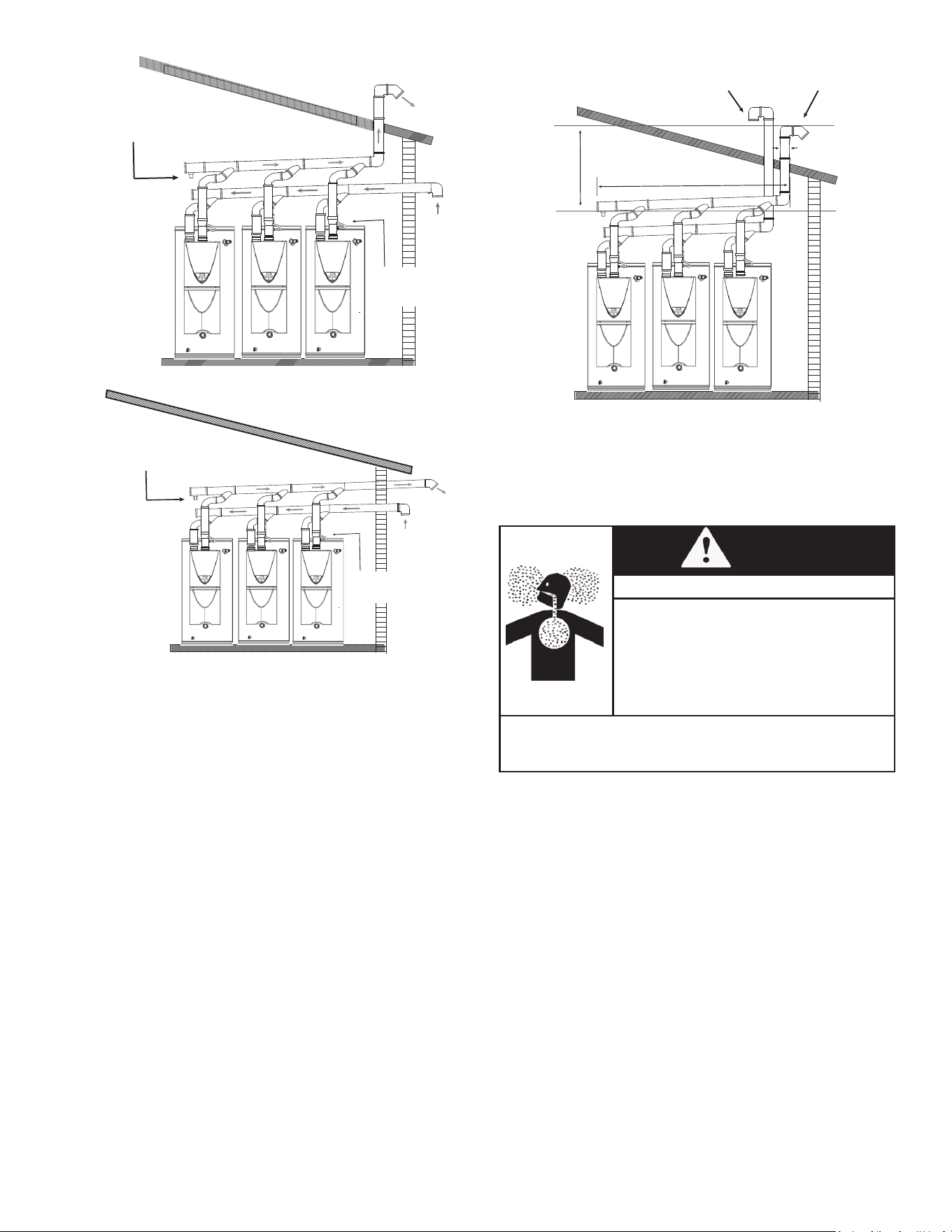
27
Elbow Terminations
“H”
“W”
“D”
Figure 29. Common Vent System Dimensions
NOTE: Regarding the clearances between the exhaust
termination and the intake termination, refer to Table 18
(page 34).
NOTE: Insert bird screen in elbow terminations
WARNING
Breathing Hazard
Where multiple appliances have a
common vent configuration, a
non-operating appliance can draw
combustion gasses, including carbon
monoxide, into the living space unless a
non-return valve is installed as directed.
Breathing carbon monoxide can cause brain damage and
death. Always read and understand the instruction manual
For detailed instructions on the common-venting system,
refer to the instructions that are packaged with the vent
parts or web site.
Intake
Exhaust
Condensate Drain Port
Non Return
Valve
Figure 27. Common Vent, Horizontal Intake, Vertical Vent
Intake
Exhaust
Condensate Drain Port
Non Return
Valve
Figure 28. Common Vent, Horizontal Intake, Horizontal Vent
For details on the installaon of a common-vent system,
please refer to "Common Venng Gas Water Heaters."
It is a manual which is available on the water heater
manufacturer's website.
DETERMINING COMMON VENT SYSTEM DIMENSIONS
Determine the vent diameter (D) and the total vent length
based on the number of water heaters installed. The total
vent length (L) consists of the horizontal width (W) and the
vertical height (H). See Table 16 (page 28).
• Total vent length (L)="H"+"W"
• Vent diameter="D"
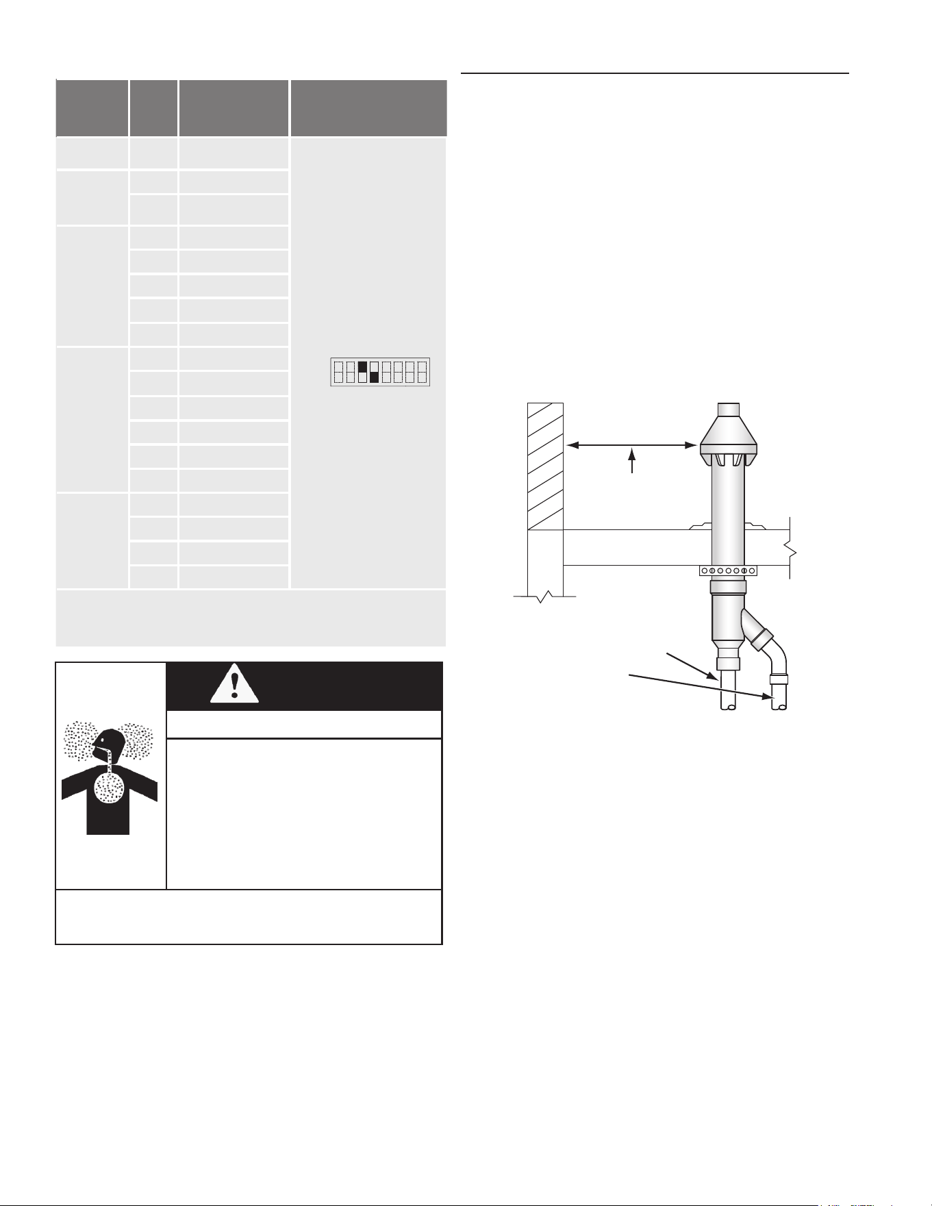
28
CONCENTRIC TERMINATION INSTALLATION PREPARATION
1. Concentric terminations must be ordered separately.
Contact your local distributor or call the parts department
phone number on the back cover of this manual to order
concentric terminations.
2. Determine the location for the termination.
NOTE: Roof termination is preferred since it is less
susceptible to damage, has reduced chances to
intake contaminants, and vent vapors are less visible.
3. When installing a concentric termination vertically
through the roof; ensure that all exterior vertical clearance
requirements for the concentric termination, shown in
Figure 32 (page 29), are being maintained. These
clearances and those cited by local and national codes
must be maintained.
4. When installing a concentric termination vertically
through a at roof, the termination's vent cap must be a
minimum of 10 feet (3 m) away from any parapet, vertical
wall or structure, as shown in Figure 30 (page 28).
CONCENTRIC TERMINATION(S)
MUST BE A MINIMUM OF 10 FEET
(3 m) AWAY FROM ANY PARAPET,
VERTICAL WALL OR
STRUCTURE.
VENT PIPE
INTAKE AIR PIPE
Figure 30. Concentric Termination - Flat Roof Clearance
NOTE: If this required 10 foot (3 m) distance to
a parapet, vertical wall, or structure cannot be
maintained, standard terminations must be used.
5. When installing a concentric termination through a
sidewall, ensure that all exterior sidewall clearance
requirements for the termination, shown in Figure 35
(page 34), are being maintained. These clearances
and those cited by local and national codes must be
maintained.
6. Cut a seven-inch (18 cm) diameter hole for the six-inch
concentric terminal where the termination will pass
through the wall or roof.
NOTE: Beware of concealed wiring and piping when
cutting through the wall or roof.
7. Determine if the concentric termination will need to
be shortened to accommodate required clearances or
to ensure all vent caps are at the same height when
installing multiple terminations vertically through the roof
in the same location.
• See Figure 31 (page 29) for the minimum lengths
allowed for the concentric termination.
Table 16. Common-Venting System DIP Switch Settings
Vent
Diameter*
(D)
Max.
No.of
Water
Heaters
Max. Vertical and
Horizontal
(Total) Vent
Length** (L)
DIP Switch Settings
4 in.
(110 mm)
2 25 ft (7.6 m)
(Upper bank DIP
switches)
OFF
ON
1 2 3 4 5 6 7 8
No.3 : ON / No.4: OFF
5 in.
(125 mm)
2 50 ft (15.2 m)
3 20 ft (6.1 m)
6 in.
(160 mm)
2 100 ft (30.5 m)
3 75 ft (22.9 m)
4 50 ft (15.2 m
5 25 ft (7.6 m)
6 20 ft (6.1 m)
8 in.
(200 mm)
3 100 ft (30.5 m)
4 100 ft (30.5 m)
5 85 ft (25.9 m)
6 65 ft (19.8 m)
7 50 ft (15.2 m)
8 41 ft (12.5 m)
10 in.
(250 mm)
5 100 ft (30.5 m)
6 100 ft (30.5 m)
7 100 ft (30.5 m)
8 100 ft. (30.5 m)
*Diameters of pipes are in accordance with
Centrotherm's specications.
**One elbow is equivalent to 5 ft (1.5 m) linear length,
and the maximum number of elbows is 5.
WARNING
Breathing Hazard
• Turn off the power supply to the water heater
before changing the DIP switch settings.
• Adjust the appropriate DIP switches
according to model as shown. DO NOT
adjust the other DIP switches.
• (See Figure 34 (page 33) for the location
of the DIP switches.)
• Failure to observe these warnings could lead
to carbon monoxide poisoning or death.
Breathing carbon monoxide can cause brain damage
and death. Always read and understand the instruction
manual
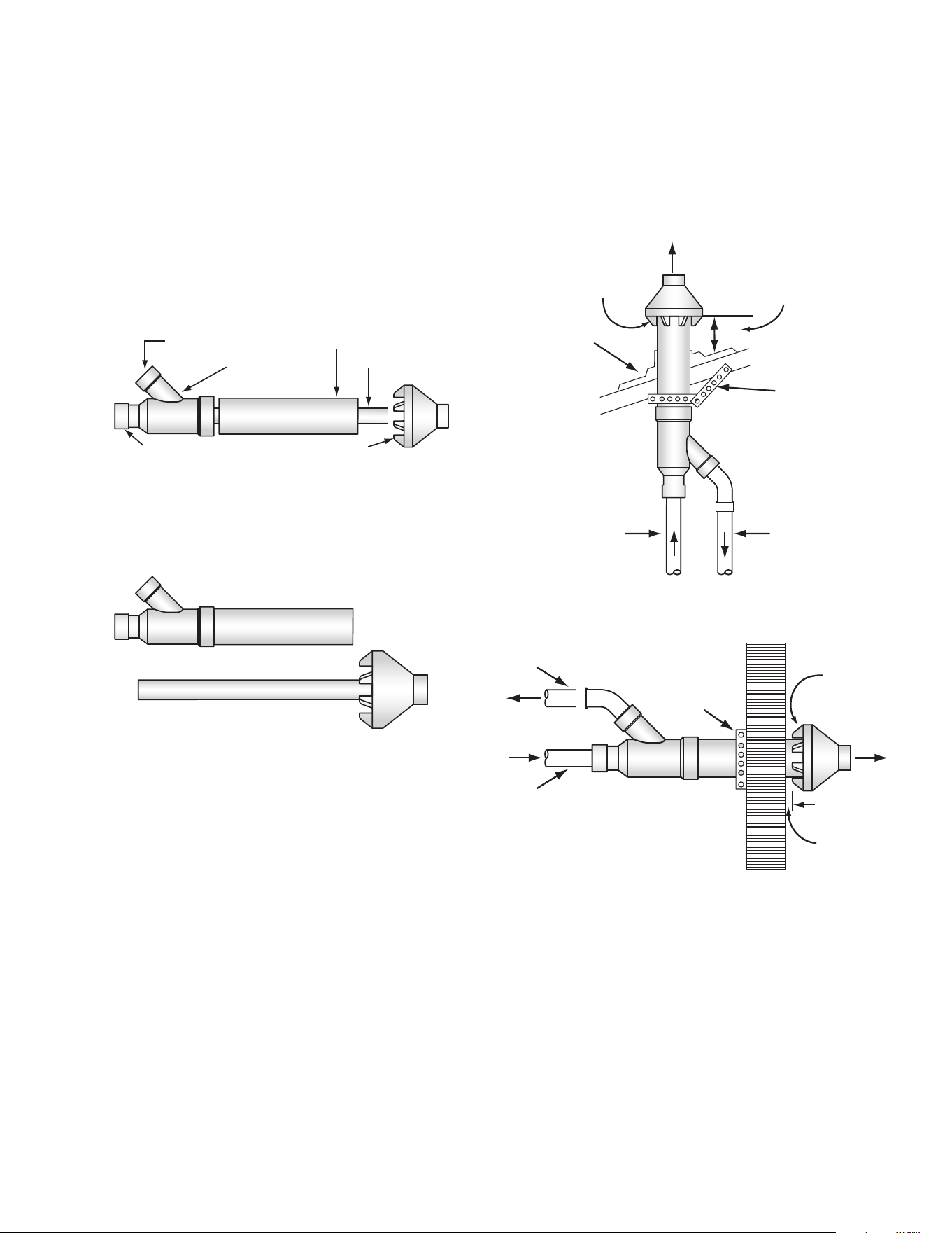
29
7. Install the vent cap/vent pipe assembly into the intake
air Y tting assembly. Ensure the small diameter vent
pipe is cemented and bottomed in the Y tting. Do not
exceed the maximum equivalent vent length listed in
Table 7 (page 21).
8. Cement all ttings and pipe in place.
9. Return to Direct Vent Installations (page 22) to
complete the installation of the intake air and vent piping
between the concentric termination and the water heater.
NOTE: SECURING STRAP
MUST BE FIELD INSTALLED
TO PREVENT MOVEMENT
OF TERMINATION KIT
MAINTAIN 12” (30 cm)
18” (45 cm) FOR CANADA
MINIMUM CLEARANCE
ABOVE HIGHEST ANTICIPATED
SNOW LEVEL. MAXIMUM OF
24” (60 cm) ABOVE ROOF.
ROOF FLASHING
(field supplied)
STRAP
(field supplied)
VENT
PIPE
INTAKE
AIR PIPE
COMBUSTION
AIR
VENT
Figure 32. Concentric Termination - Vertical Installation
INTAKE AIR PIPE
STRAP
(field supplied)
VENT PIPE
COMBUSTION
AIR
VENT
1 INCH
MAXIMUM
NOTE: SECURING STRAP MUST BE
FIELD INSTALLED TO PREVENT
MOVEMENT OF TERMINATION KIT
IN SIDEWALL.
Figure 33. Concentric Termination - Side-Wall Installation
• NOTE: When shortening the length of the termination,
carefully measure and cut the larger (intake air) pipe
rst. Cut the same amount of pipe from the smaller
(vent) pipe.
• NOTE: Lengthening of the Concentric Vent
Termination is not permitted.
8. Proceed to Concentric Termination Installation (page
29).
CONCENTRIC TERMINATION INSTALLATION
Assemble and install the four-inch concentric termination.
Refer to Figure 31, Figure 32, and Figure 33 for these
instructions:
FOUR-PIECE KIT - FIELD ASSEMBLY REQUIRED
VENT PIPE
INTAKE AIR CONNECTION
VENT CONNECTION
INTAKE AIR PIPE
Y FITTING ASSEMBLY
VENT CAP
VENT PIPE ASSEMBLY
MINIMUM ALLOWABLE LENGTH 25 INCHES (64 cm)
INTAKE AIR PIPE MAY BE SHORTENED
MINIMUM ALLOWABLE LENGTH 12 INCHES (30 cm)
VENT CAP
INTAKE AIR PIPE
Y FITTING
VENT PIPE MAY BE SHORTENED
Figure 31. Concentric Termination Kit
1. Cement the Y tting to the larger diameter intake air pipe.
2. Slide the intake air pipe and Y tting assembly from inside
the building through the hole cut for the termination in
the roof or sidewall. Ensure no foreign materials such as
insulation accumulate inside the assembly.
3. Secure the intake air Y tting assembly using eld
supplied metal strapping or equivalent support materials.
4. On installations installed through the roof, slide a eld-
supplied plumbing boot or roof ashing over the intake
air Y-tting assembly and secure it to the roof.
5. Seal around the plumbing boot or roof ashing.
6. Cement the vent cap onto the vent pipe. Alternately
a eld-supplied stainless steel screw may be used
to secure the two components together when field
disassembly is desired for cleaning. A pilot hole must be
drilled for the screw to prevent damage/cracking of the
vent cap and/or vent pipe.
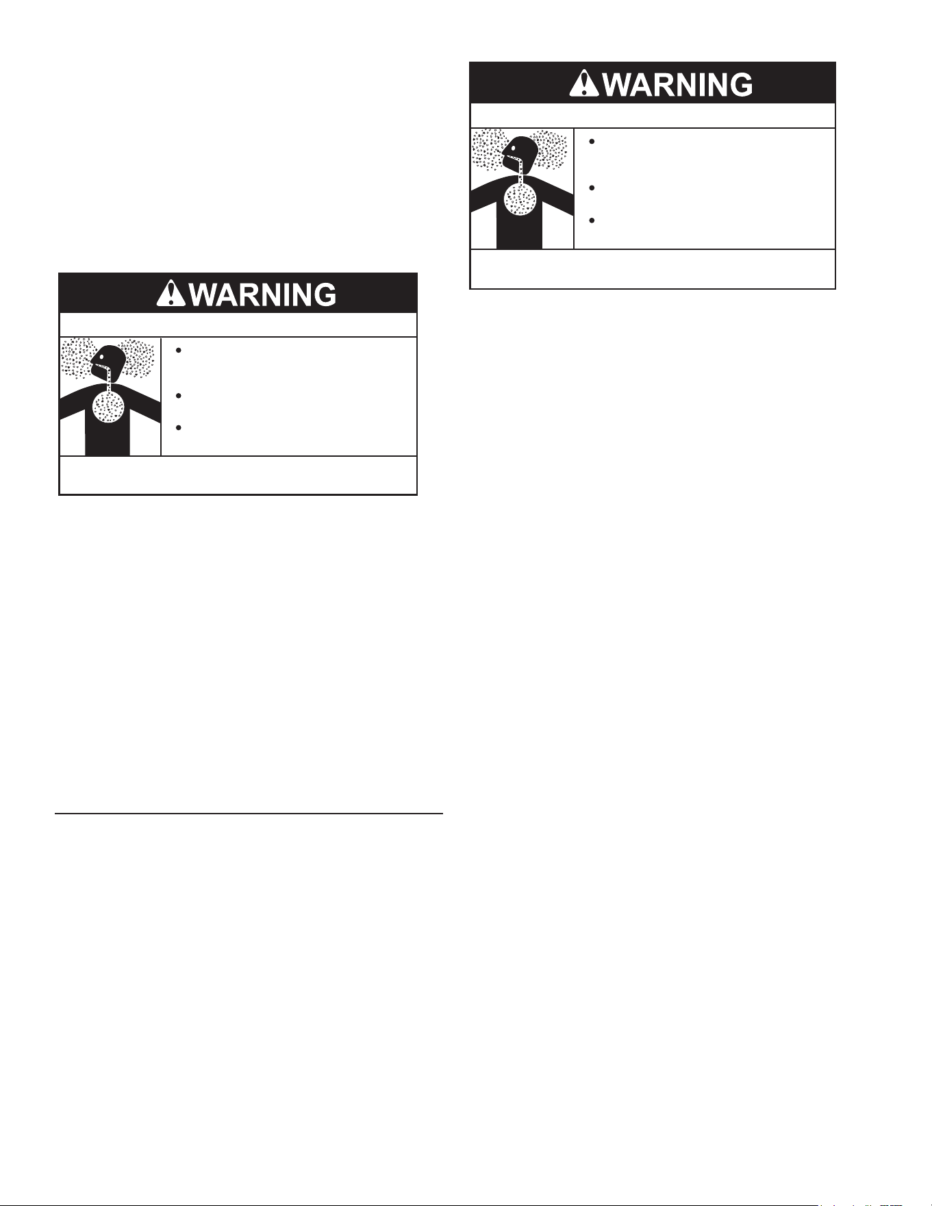
30
Breathing Hazard - Carbon Monoxide Gas
Install water heater in accordance with
the Instruction Manual and NFPA 54 or
CAN/CSA-B149.1.
To avoid injury, combustion and ventilation
air must be taken from outdoors.
Do not place chemical vapor emitting
products near water heater.
Breathing carbon monoxide can cause brain damage or
death. Always read and understand instruction manual.
Do not install the water heater in a conned space unless
an adequate supply of air for combustion and ventilation
is brought in to that space using the methods described in
Conned Space (page 30).
Never obstruct the ow of ventilation air. If you have any
doubts or questions at all, call your gas supplier. Failure
to provide the proper amount of combustion air can result
in a re or explosion and cause property damage, serious
bodily injury, or death.
UNCONFINED SPACE
An unconned space is one in which the volume IS NOT
LESS THAN 50 cubic feet per 1,000 Btu/hr (4.8 cubic
meters per kW) of the total input rating of all appliances
installed in the space. Rooms communicating directly with
the space in which the appliances are installed, through
openings not furnished with doors, are considered a part
of the unconned space.
Makeup air requirements for the operation of exhaust fans,
kitchen ventilation systems, clothes dryers and replaces
shall also be considered in determining the adequacy of a
space to provide combustion, ventilation and dilution air.
UNUSUALLY TIGHT CONSTRUCTION
In unconfined spaces in buildings, infiltration may be
adequate to provide air for combustion, ventilation, and
dilution of ue gases. However, in buildings of unusually
tight construction (for example, weather stripping, heavily
insulated, caulked, vapor barrier, etc.), additional air must
be provided using the methods described in the Conned
Space (page 30) section that follows.
CONFINED SPACE
A conned space is one in which the volume is less than
50 cubic feet per 1,000 Btu/hr (4.8 cm per kW) of the total
input rating of all appliances installed in the space.
Openings must be installed to provide fresh air for
combustion, ventilation, and dilution in conned spaces.
The required size for the openings depends on the method
used to provide fresh air to the conned space and the total
Btu/hr input rating of all appliances installed in the space.
CONTAMINATED AIR
Corrosion of the ue ways and vent system may occur if
air for combustion contains certain chemical vapors. Such
corrosion may result in failure and risk of asphyxiation.
Combustion air that is contaminated can greatly diminish the
life span of the water heater and water heater components
such as igniters and burners. Propellants of aerosol
sprays, beauty shop supplies, water softener chemicals
and chemicals used in dry cleaning processes that are
present in the combustion, ventilation or ambient air can
cause such damage.
Breathing Hazard - Carbon Monoxide Gas
Install water heater in accordance with
the Instruction Manual and NFPA 54 or
CAN/CSA-B149.1.
To avoid injury, combustion and ventilation
air must be taken from outdoors.
Do not place chemical vapor emitting
products near water heater.
Breathing carbon monoxide can cause brain damage or
death. Always read and understand instruction manual.
Do not store products of this sort near the water heater.
Air which is brought in contact with the water heater
should not contain any of these chemicals. If necessary,
uncontaminated air should be obtained from remote or
outdoor sources. The limited warranty is voided if the
water heater fails due to a corrosive atmosphere. See the
Commercial Integrated Tankless on Tank Limited Warranty
provided with this water heater.
If the water heater will be used in beauty shops, barber
shops, cleaning establishments, or self-service laundries
with dry cleaning equipment, it is imperative that the water
heater(s) be installed in a direct vent conguration so
that all air for combustion comes directly from the outdoor
atmosphere through a sealed intake air pipe. See Direct
Vent Installations (page 22).
AIR REQUIREMENTS
For safe operation, an adequate supply of fresh
uncontaminated air for combustion and ventilation must
be provided.
An insufcient supply of air can cause recirculation of
combustion products resulting in contamination that may
be hazardous to life. Such a condition often will result in
a yellow, luminous burner ame, causing sooting of the
combustion chamber, burners and ue tubes, and creates
a risk of asphyxiation.

31
DIRECT VENT APPLIANCES
Appliances installed in a direct vent conguration that get
all air for combustion from the outdoor atmosphere through
sealed intake air piping do not factor into the total appliance
input Btu/hr calculations that determine the size of openings
required to provide fresh air in conned spaces.
EXHAUST FANS
Where exhaust fans are installed, additional air shall be
provided to replace the exhausted air. When an exhaust
fan is installed in the same space with a water heater,
sufcient openings to provide fresh air must be provided
that accommodate the requirements for all appliances in the
room and the exhaust fan. Undersized openings cause air
to be drawn into the room through the water heater’s vent
system causing poor combustion. Sooting, serious damage
to the water heater, and the risk of re or explosion may
result. It can also create a risk of asphyxiation.
LOUVERS AND GRILLES
The free areas of the fresh air openings in the instructions
that follow do not take in to account the presence of louvers,
grilles or screens in the openings.
The required size of openings for combustion, ventilation
and dilution air shall be based on the “net free area” of each
opening. Where the free area through a design of louver or
grille or screen is known, it shall be used in calculating the
size of opening required to provide the free area specied.
Where the louver and grille design and free area are not
known, it shall be assumed that wood louvers will have
25% free area and metal louvers and grilles will have 75%
free area. Non motorized louvers and grilles shall be xed
in the open position.
For examples of congurations that can be used to ensure
an adequate combustion air supply, see Combustion Air
Supply Options (page 20).

32
INSTALLATION REQUIREMENTS - COMMONWEALTH OF MASSACHUSETTS
For all side wall terminated, horizontally vented power vent,
direct vent, and power direct vent gas fueled water heaters
installed in every dwelling, building or structure used in
whole or in part for residential purposes, including those
owned or operated by the Commonwealth and where the
side wall exhaust vent termination is less than seven (7) feet
above nished grade in the area of the venting, including but
not limited to decks and porches, the following requirements
shall be satised:
INSTALLING CARBON MONOXIDE DETECTORS
At the time of installation of the side-wall horizontal-vented
gas-fueled equipment, the installing plumber or gas-tter
shall observe that a hard-wired carbon-monoxide detector,
with an alarm and battery back-up, is installed on the oor
level where the gas equipment is to be installed. In addition,
the installing plumber or gas-tter shall observe that a
battery-operated or hard-wired carbon-monoxide detector,
with an alarm, is installed on each additional level of the
dwelling, building, or structure served by the side-wall
horizontal-vented gas-fueled equipment. It shall be the
responsibility of the property owner to secure the services
of qualied licensed professionals for the installation of
hard-wired carbon-monoxide detectors.
In the event that the side-wall horizontally-vented gas-fueled
equipment is installed in a crawl space or an attic, the hard-
wired carbon-monoxide detector, with alarm and battery
back-up, may be installed on the next adjacent oor level.
In the event that the requirements of this subdivision can not
be met at the time of completion of installation, the owner
shall have a period of thirty (30) days to comply with the
above requirements provided that during said thirty (30)
day period, a battery-operated carbon-monoxide detector,
with an alarm, shall be installed.
APPROVED CARBON MONOXIDE DETECTORS
Each carbon-monoxide detector as required in accordance
with the above provisions shall comply with NFPA 720 and
be ANSI/UL 2034 listed and CSA certied.
SIGNAGE
A metal or plastic identication plate shall be permanently
mounted to the exterior of the building at a minimum height
of eight (8) feet above grade directly in line with the exhaust
vent terminal for the horizontally-vented gas-fueled heating
appliance or equipment. The sign shall read, in print size no
less than one-half (1/2) inch in size, “GAS VENT DIRECTLY
BELOW. KEEP CLEAR OF ALL OBSTRUCTIONS.”
INSPECTION
The state or local gas inspector of the side-wall horizontally-
vented gas-fueled equipment shall not approve the
installation unless, upon inspection, the inspector observes
carbon-monoxide detectors and signage installed in
accordance with the provisions of 248 CMR 5.08(2)(a) 1
through 4.
EXEMPTIONS
The following equipment is exempt from 248 CMR 5.08(2)
(a)1 through 4:
1. The equipment listed in Chapter 10 entitled “Equipment
Not Required To Be Vented” in the most current edition
of NFPA 54 as adopted by the Board; and
2. Product Approved side-wall horizontally-vented gas-
fueled equipment installed in a room or structure
separate from the dwelling, building, or structure used
in whole or in part for residential purposes.
MANUFACTURER REQUIREMENTS - GAS EQUIPMENT
VENTING SYSTEM PROVIDED
When the manufacturer of Product Approved side-wall
horizontally-vented gas-fueled equipment provides a
venting system design or venting system components
with the equipment, the instructions provided by the
manufacturer for installation of the equipment and the
venting system shall include:
1. Detailed instructions for the installation of the venting-
system design or the venting-system components
2. A complete parts list for the venting-system design or
venting system.
MANUFACTURER REQUIREMENTS - GAS EQUIPMENT
VENTING SYSTEM NOT PROVIDED
When the manufacturer of a Product Approved side-wall
horizontally-vented gas-fueled equipment does not provide
the parts for venting the ue gases, but identies “special
venting systems,” the following requirements shall be
satised by the manufacturer:
1. The referenced “special venting system” instructions
shall be included with the appliance or equipment
installation instructions.
2. The “special venting systems” shall be Product
Approved by the Board, and the instructions for that
system shall include a parts list and detailed installation
instructions.
A copy of all installation instructions for all Product
Approved side-wall horizontally-vented gas-fueled
equipment, all venting instructions, all parts lists for venting
instructions, and/or all venting-design instructions shall
remain with the appliance or equipment at the completion
of the installation.
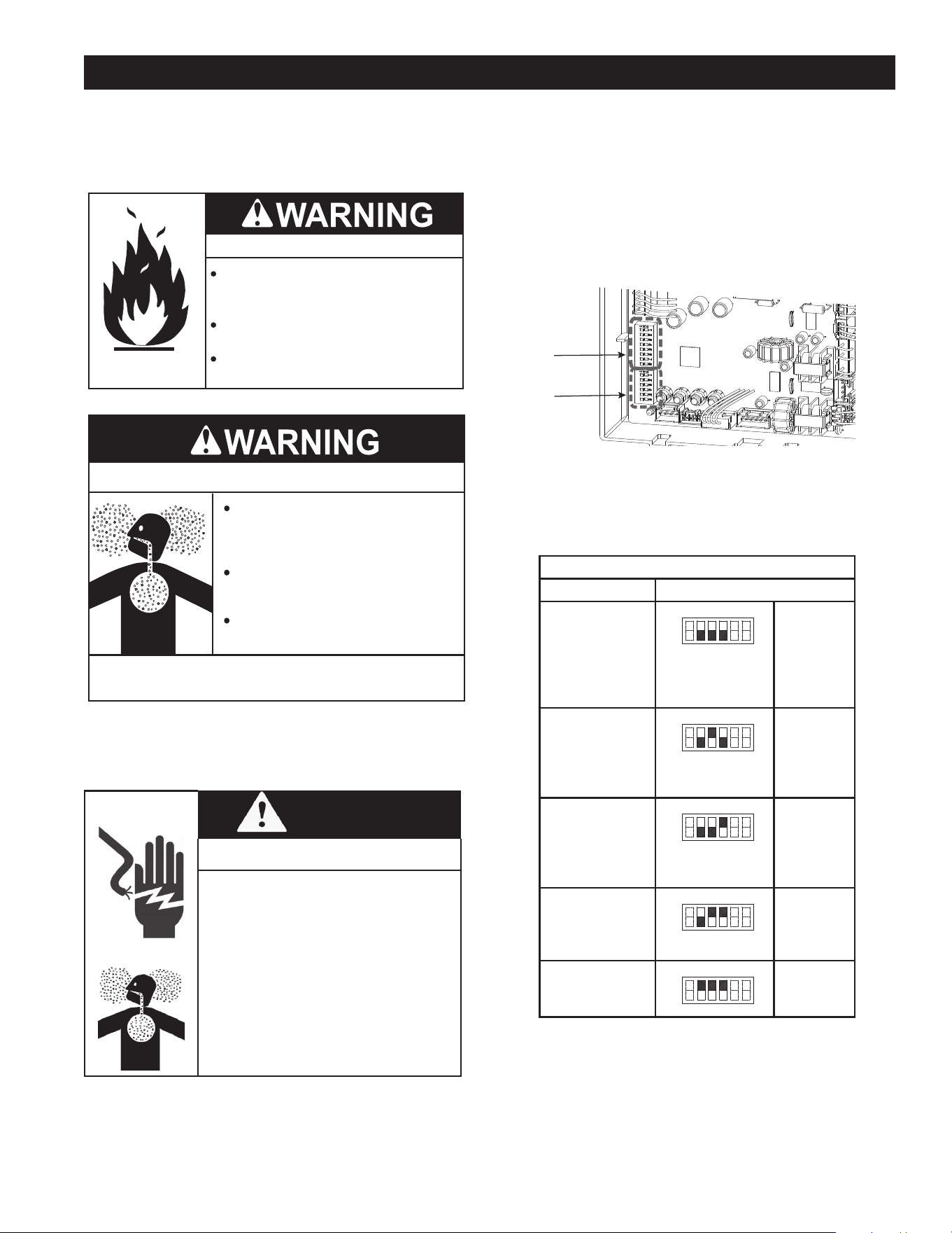
33
If the water heater is installed at a location with an elevation
above 2000 feet (611 m), proper operation requires
the adjustment of the combustion parameters. These
parameters correspond to lower-bank DIP switches on the
computer board.
Fire and Explosion Hazard
Gas and carbon monoxide detectors are
available.
Overfiring could result in fire or
explosion.
Under no circumstances should the
input exceed the rate shown on the
water heater’s rating label.
Breathing Hazard - Carbon Monoxide Gas
Breathing carbon monoxide can cause brain damage or
death. Always read and understand instruction manual.
Under no circumstances should
the input exceed the rate shown
on the water heater’s rating label.
Overfiring could result in damage to
the water heater and sooting.
Gas and carbon monoxide detectors
are available.
• Warning: Turn off the power supply to the water
heater before changing the DIP switch settings.
• Warning: Failure to observe these warnings could
lead to carbon monoxide poisoning or death.
WARNING
Shock or Breathing Hazard
• Turn off the power supply to the
water heater before changing the
DIP switch settings.
• Failure to observe these warnings
could lead to carbon monoxide
poisoning or death.
HIGH-ALTITUDE INSTALLATIONS
Do the following to adjust the water heater for high-altitudes:
1. Check the elevation where your water heater is installed.
Find your altitude in Table 17.
2. Disconnect power supply from the water heater.
3. Take off the water heater’s upper front cover.
4. Locate the computer board in the unit case. See Figure
3 (page 8).
5. Remove the computer board cover.
6. Locate the lower bank DIP switches on the computer
board.
Upper DIP
Switch
Bank
Lower DIP
Switch Bank
Figure 34. Location of DIP Switches
7. On the lower DIP switch bank, note the position of DIP
switches 2, 3, and 4.
Table 17 shows the DIP switch settings for the range of
altitudes. The DIP switches are the lower bank DIP switches.
Table 17. High Altitude DIP Switch Settings
Altitude DIP Switch Settings
0 to 2,000 ft
(0 to 610 m)
(DEFAULT)
OFF
ON
1 2 3 4 5 6
No. 2 :
OFF
No. 3 :
OFF
No. 4 :
OFF
2,000 to
3,000 ft
(611 to 914 m)
OFF
ON
1 2 3 4 5 6
No. 2 :
OFF
No. 3 : ON
No. 4 :
OFF
3,000 to
5,000 ft
(915 to 1,524 m)
OFF
ON
1 2 3 4 5 6
No. 2 :
OFF
No. 3 :
OFF
No. 4 : ON
5,000 to
7,500 ft
(1,525 to 2,286 m)
OFF
ON
1 2 3 4 5 6
No. 2 :
OFF
No. 3 : ON
No. 4 : ON
7,500 to
10,100 ft
(2,287 to 3,078 m)
OFF
ON
1 2 3 4 5 6
No. 2 : ON
No. 3 : ON
No. 4 : ON
NOTE: The dark squares indicate the correct DIP switch
positions.
Maximum Certied or Allowable Installed Altitude: 10,100
ft (3,078 m)
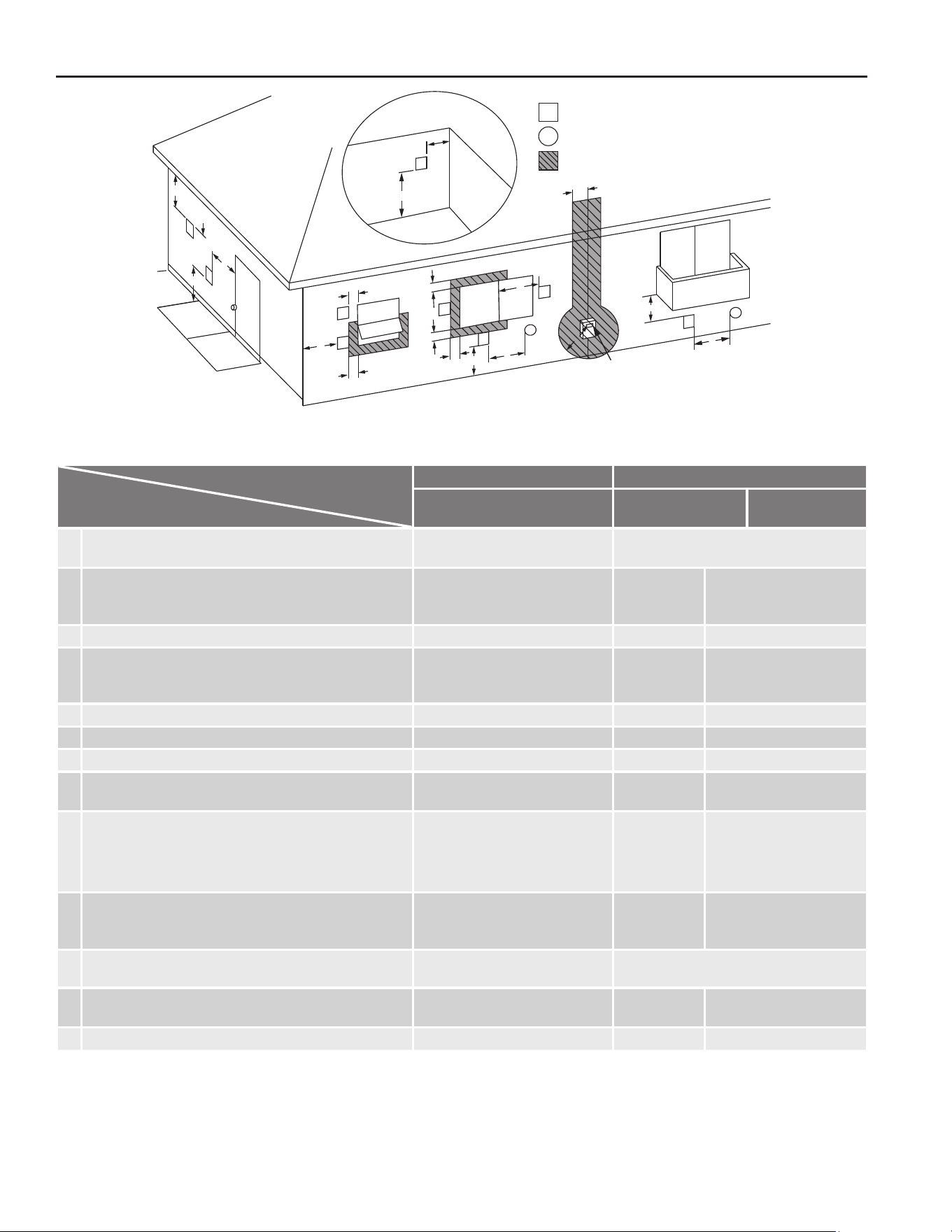
34
TERMINATION CLEARANCES FOR SIDEWALL INSTALLATIONS
H
D
E
L
B
V
V
V
V
B
F
C
B
B
B
V
V
V
V
V
X
X
A
J
M
Operable
Fixed
closed
Fixed
closed
Operable
B
Inside corner
detail
G
A
K
V
X
= Vent terminal
= Air supply inlet
= Area where the terminal
is not permied
Regulator/Gas meter
vent outlet
I
Figure 35. Vent Termination Clearances
Table 18. Vent Termination Clearances for Direct Vent and Other Vent Systems
Canada Installations
1
US Installations
2
Direct Vent/Other Than
Direct Vent
Direct vent
Other Than
Direct Vent
A
Clearance above grade, veranda, porch, deck, or
balcony
1 ft (30 cm) 1 ft (30 cm)
B Clearance to window or door that may be opened
3 ft (91 cm)
1 ft
(30 cm)
4 ft (1.2 m) below or to
side of opening; 1 ft (30
cm) above opening
C Clearance to permanently closed window
0 0 0
D
Vertical clearance to ventilated soft located above
the vent terminator within a horizontal distance of 2
feet (61cm) from the center line of the termination
3 ft (91 cm) 3 ft (91 cm) 3 ft (91 cm)
E Clearance to unventilated soft
3 ft (91 cm) 3 ft (91 cm) 3 ft (91 cm)
F Clearance to outside corner
2 ft (61 cm) 2 ft (61 cm) 2 ft (61 cm)
G Clearance to inside corner
2 ft (61 cm) 2 ft (61 cm) 2 ft (61 cm)
H
Clearance to each side of center line extended
above meter/regulator assembly
3 ft (91 cm) * *
I Clearance to service regulator vent outlet
Above a regulator within 3 ft (91
cm) horizontally of the vertical
center line of the regulator vent
outlet to a maximum vertical
distance of 15 ft (4.5 m)
* *
J
Clearance to non-mechanical air supply inlet to
building or the combustion air inlet to any other
appliance.
3 ft (91 cm) 1 ft (30 cm)
4 ft (1.2 m) below or to
side of opening; 1 ft (30
cm) above opening
K Clearance to mechanical air supply inlet
6 ft (183 cm)
3 ft (91 cm) above
if within 10 ft (3 m) horizontally.
L
Clearance above paved sidewalk or paved drive-
way located on public property
7 ft (213 cm)** 7 ft (213 cm) 7 ft (213 cm)
M Clearance under veranda, porch deck, or balcony
1 ft (30 cm)*** 1 ft (30 cm)*** 1 ft (30 cm)***
*Clearance in accordance with local installation codes and the requirements of the gas supplier.
**A vent shall not terminate directly above a sidewalk or paved driveway that is located between two single family dwellings and serves both dwellings.
***Permitted only if veranda, porch, deck, or balcony is fully open on a minimum of two sides beneath the oor.
The vent for condensing water heaters shall not terminate:
1) Over public walkways; or
2) Near soft vents or crawl space vents or other areas where condensate or vapor could create a nuisance or hazard or cause property damage; or
3) Where condensate vapor could cause damage or could be detrimental to the operation of regulators, relief valves, or other equipment.
Notes:
1) In accordance with the current CSA B149.1, Natural Gas and Propane Installation Code
2) In accordance with the current ANSI Z223.1/NFPA 54, National Fuel Gas Code
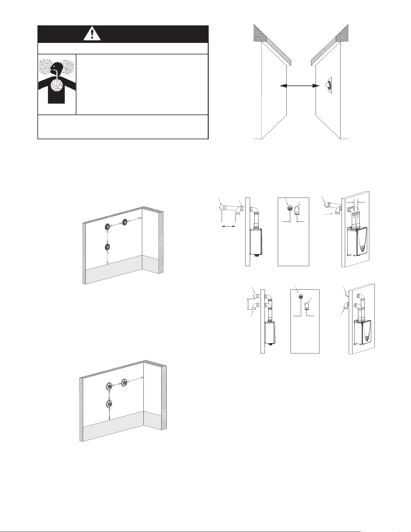
35
2 ft (610 mm) min.
Exhaust
Termination
Figure 36. Clearance From Adjacent Buildings
Case 1: Long Terminations
For direct vent sidewall terminations that use two separate
penetrations for the intake and exhaust, keep the termination
clearances shown in the diagrams.
1 (305 mm)
min.
Exhaust
Intake
Exhaust
Intake
0.5 ft (159 mm)
min.
Exhaust
Intake
0.5 ft (159 mm)
min.
Case 2: Shorter Terminations
Exhaust
Exhaust
Exhaust
Intake
Intake
Intake
1 ft
(305 mm) min.
0.5 ft (159 mm)
min.
WARNING
Breathing Hazard
Improper installation can result in carbon
monoxide poisoning or death. Follow all
local and national codes in regards to proper
termination clearances. In the absence of
such codes, the clearances below can be
used as guidelines. Local codes supersede
these guidelines.
Breathing carbon monoxide can cause brain damage
or death. Always read and understand the instruction
manual.
Multiple Sidewall Terminations
An exhaust termination must be at least 1 ft (305 mm) away
from another exhaust termination. An exhaust termination
must also be at least 2 ft (610 mm) away from an inside
corner. (If the adjacent wall is less than 2 ft (610 mm) of
length, the minimum required distance away from the inside
corner will be equal to the length of that adjacent wall.)
Ancipated Snow level
Exhaust
Terminaon
2
(610 mm)
min.
1
(305 mm)
min.
1
(305 mm)
min.
Inside
corner
Multiple DV Sidewall Terminations
A direct vent (DV) termination must be at least 1 ft (305 mm)
away from other direct vent terminations.
A direct vent termination must also be at least 2 ft (610 mm)
away from an inside corner. (If the adjacent wall is less than
2 ft (610 mm) of length, the minimum required distance
away from the inside corner will be equal to the length of
that adjacent wall.)
Inside
corner
Ancipated Snow level
2
(610 mm)
min.
1
(305 mm)
min.
1
(305 mm)
min.
Combined
intake and
exhaust
terminaon
Adjacent Buildings
Exhaust and/or direct vent sidewall terminations should be
at least 2 ft (610 mm) away from an opposite surface/wall.
Do not place the termination directly in front of an opening
into a building.
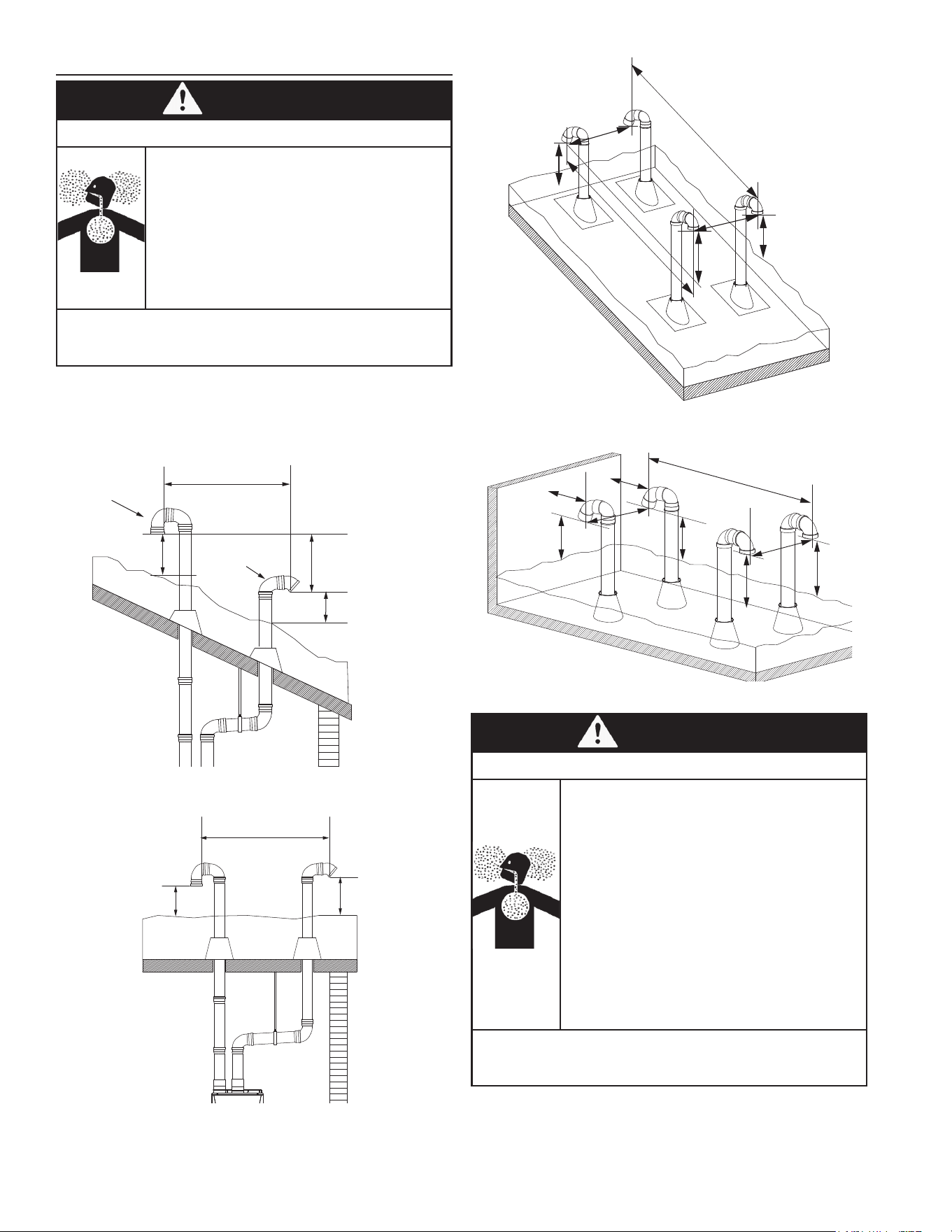
36
Exhaust gas
Exhaust
gas
Intake air
Intake air
1
(305 mm)
min.
1
(305 mm)
min.
1
(305 mm)
min.
1
(305 mm)
min.
2 (610 mm) min.
Ancipated snow level
1
(305 mm)
min.
3 (914 mm) min.
Figure 39. Multiple Angled Roof Terminations
Vercal wall
Ancipated snow level
1
(305 mm)
min.
1
(305 mm)
min.
2
(610 mm)
min.
2
(610 mm)
min.
1
(305 mm)
min.
1
(305 mm)
min.
1
(305 mm)
min.
1
(305 mm)
min.
3 (914 mm) min.
Exhaust gas
Exhaust gas
Intake air
Intake air
Figure 40. Multiple Flat Roof Terminations
WARNING
Breathing Hazard
• Exhaust terminations must be at least 1 ft (305
mm) away from any obstructions.
• Minimum spacing between multiple terminals:
• Intake terminals: 1 ft (305 mm) spacing
between each
• Exhaust terminals: 1 ft (305 mm) spacing
between each
• The exhaust termination must be a horizontal
distance of at least 2 ft (610 mm) from a wall or
surface unless specied differently by local code.
• Failure to observe this warning may result in severe
personal injury or death.
Breathing carbon monoxide can cause brain damage
or death. Always read and understand the instruction
manual.
CLEARANCES FOR ROOFTOP TERMINATIONS
WARNING
Breathing Hazard
Follow all local and national codes in
regards to proper termination clearances.
In the absence of such codes, the
clearances below must be met. Local
codes supersede these clearances.
Failure to observe this warning may result
in severe personal injury or death.
Breathing carbon monoxide can cause brain damage
or death. Always read and understand the instruction
manual.
Note: Canadian requirements differ from the guidelines in
this section. In Canada, follow the requirements of B149.1
(Natural Gas and Propane Installation Code, current edition)
as well as local and provincial codes. Contact your local
code enforcement agency for direction.
2 ft (610 mm) min.
Exhaust
Intake
1 ft
(305 mm) min
1 ft
(305 mm) min
1 ft
(305 mm) min
Anticipated
Snow Level
Figure 37. Angled Roof Termination
3 ft (914 mm) min
Exhaust
Intake
1 ft
(305 mm) min.
1 ft
(305 mm) min.
Anticipated
Snow Level
Figure 38. Flat Roof Termination
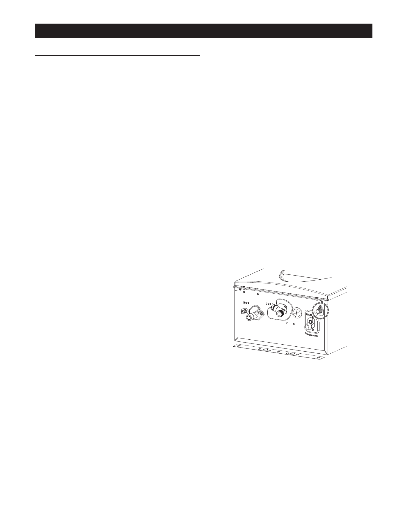
37
WATER HEATER INSTALLATION
neutralizer elements inside the Neutralizer accessory
have been completely consumed. If this happens,
condensate will remain acidic and can possibly cause
damage to items such as pipes, concrete, etc., if drained
improperly.
• The actual life of the neutralizer may vary, depending on
the application and usage. Replace the cartridge when
the condensate pH goes below 6.0.
• Please ensure that the cartridge is properly replaced
before the neutralizer elements have been completely
consumed.
• All preventative measures and safety practices must be
adhered to when draining condensate. The manufacturer
will not be responsible for any damage caused by
condensate.
• A drain pan, or other means of protection against water
damage, is recommended to be installed under the water
heater in case of leaks.
CONDENSATE DRAIN INSTALLATION INSTRUCTIONS
The water heater is a high efciency condensing water
heater that produces condensate (acidic water). The acidic
condensate generated in the secondary heat exchanger can
be neutralized by the neutralizer accessory (100112159/
TH-NT01).
Although a neutralizer is not required, a condensate drain
must be installed as described on the next page.
Figure 41. Water Heating Unit Condensate Drain Port
WATER HEATING UNIT CONDENSATE DRAIN
Condensate can accumulate within the water heating unit.
In the absence of applicable local codes and regulations,
the manufacturer recommends that condensate be disposed
of into a drain. Connect a drain tube from the condensate
drain port located on the bottom of the water heater to a
standard drain. See Figure 43 (page 38).
The condensate that accumulates from the water heating
unit can be acidic. Local codes and regulations might require
that the condensate be neutralized before being discharged
into a drain. If required by local codes and regulations, an
accessory neutralizer assembly (100112159/TH-NT01) is
available for purchase separately. See Figure 43 (page
38).
Installation of the condensate drain must conform with these
instructions and local building codes.
Follow these instructions and all code requirements of the
local authority for condensate neutralizers, whether or not
they are required for the installation.
INSTALLATION NOTES
• Discharge condensate (acidic water) in accordance with
all local codes and common safety practices.
• Use corrosion resistant pipe, such as PVC, for the
condensate drain line.
• Do not use metal pipe.
• The condensate drain does not require a trap.
• Maintain a downward slope on the drain line(s), including
installations in which the drain is not directly below the
water heater.
• A eld-supplied bypass is required if a neutralizer is
installed.
• Do not connect the condensate drain line directly to a
condensate pump.
• If the drain line is required to have bends, ensure
that there are no kinks that will restrict the ow of
condensation.
• The condensate drain is at atmospheric pressure (non-
pressurized) and therefore must be allowed to drain
freely with gravity only. Ensure that the condensate
drain tube is not plugged or blocked, and ensure that it
slopes downward to allow condensate to ow freely. All
portions of the condensate drain (neutralizer and drain
tube) must be at a lower elevation than the water heater
to prevent condensate water from building up inside the
water heating unit.
• Condensate cannot be effectively neutralized if the
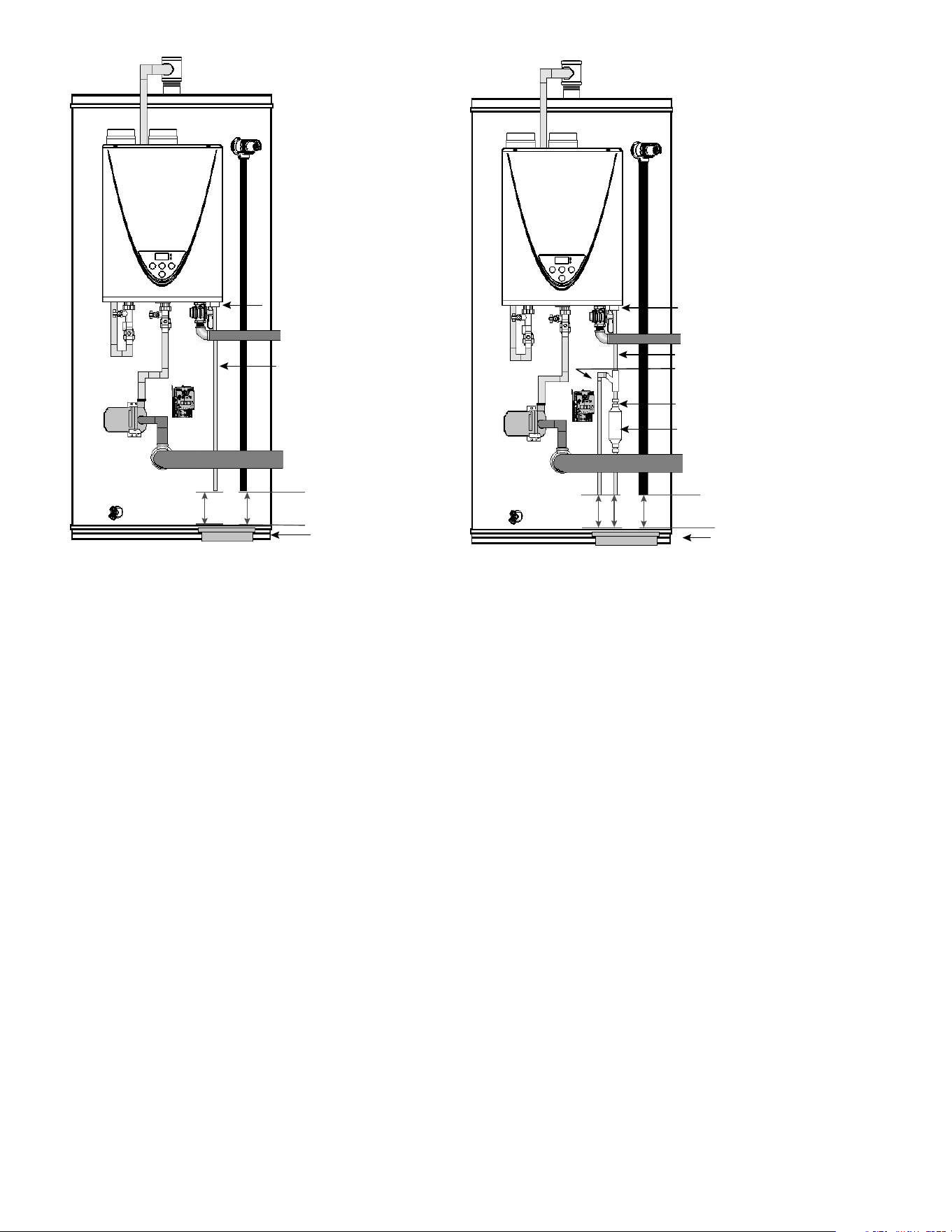
38
Condensate drain tube*
6" (152 mm) MAX. air gap
Floor drain, standpipe,
or other acceptable drain
1/2" MPT x 3/8" FPT
(Included with Neutralizer accessory)
Neutralizer cartridge
(Included with Neutralizer accessory)
Overow bypass*
(1/2" Condensate drain tube)
1/2" MPT condensate connection
2” (50 mm)
MIN. distance**
Figure 43. 1/2" Drain Tube/Neutralizer Cartridge Installed
*Maintain downward slope, including installations in which the
drain is not directly below the heater.
**A two-inch (50 mm) air gap must be maintained between the
condensate line and drain to allow full flow of the condensa-
tion.
1/2" MPT condensate connection
6" (152 mm) MAX. air gap
Floor drain, standpipe,
or other acceptable drain
Condensate drain tube*
2” (50 mm)
MIN. distance**
Figure 42. 1/2" Drain Tube Installed
*Maintain downward slope, including installations in which the
drain is not directly below the heater.
**A two-inch (50 mm) air gap must be maintained between the
condensate line and drain to allow full flow of the condensa-
tion.
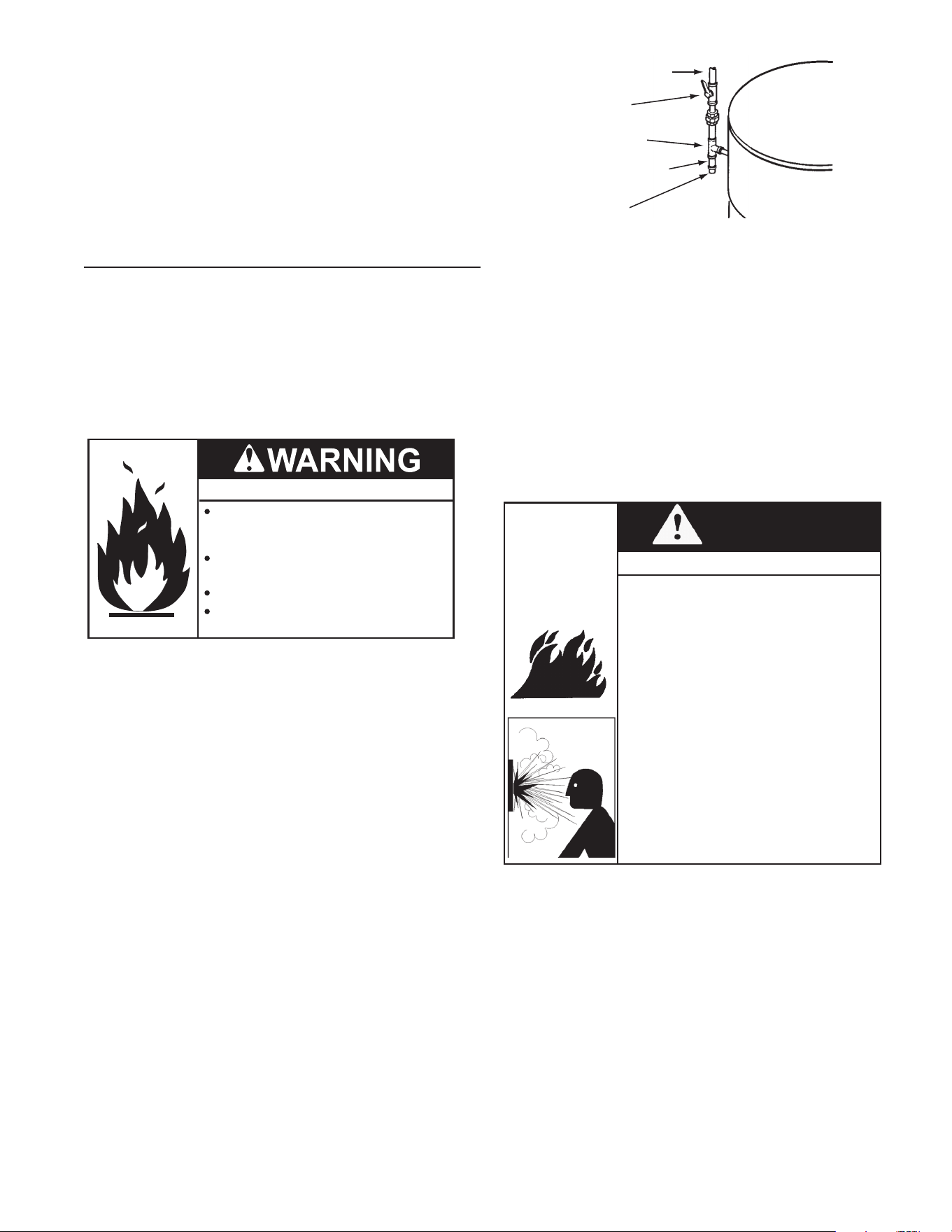
39
INSTALLATION NOTES
1. The condensate drains from the water heater’s covered
by this instruction have PH levels between 4.3 and 5.0.
Install a commercially available neutralizing kit if required
by local codes. Lower PH levels are acidic. Do not
connect a metal condensate drain line, such as copper
pipe, to the water heater for this reason.
2. The eld installed condensate drain line must not be less
than 1/2 inch PVC in size.
3. Install a proper drip leg.
SUPPLY GAS LINE INSTALLATION
Contact your local gas utility company to ensure that
adequate gas service is available and to review applicable
installation codes for your area.
Be sure that the gas meter has sufcient capacity to supply
the rated gas input of the water heater as well as the
requirements of all other gas red equipment supplied by
the meter. If the gas meter is undersized, the gas company
will have to install a properly sized gas meter.
Fire and Explosion Hazard
Turn off gas lines during installation.
Contact a qualified installer or service
agency for installation and service.
Excessive gas pressure to gas valve can
cause serious injury or death.
Do not use water heater with any gas
other than the gas shown on the rating
label.
Make sure gas supplied is same type listed on the water
heater’s rating label.
The water heaters covered in this manual are not intended for
operation at higher than 14.0" W. C. (2.62 kPa) for natural gas and
14.0" W. C. (3.49 kPa) for propane gas supply pressure, see Table 2
(page 10). The water heaters covered in this manual require supply
gas regulators to maintain required supply gas pressure. Exposure to
higher gas supply pressure may cause damage to the gas controls
which could result in re or explosion. If overpressure has occurred
such as through improper testing of gas lines or malfunction of the
supply system the water heater’s gas valve must be checked for safe
operation by a Qualied Service Agency.
Ensure supply regulator vent lines and the safety vent valves are
protected against blockage. These are components of the gas supply
system, not the water heater. Vent blockage may occur during ice
storms.
It is important to guard against gas valve fouling from contaminants
in the gas ways. Such fouling may cause improper operation, re or
explosion. If copper supply lines are used they must be internally
tinned and certied for gas service.
REGULATED GAS
SUPPLY LINE
MAIN GAS
SHUTOFF VALVE
TEE FITTING
PIPE CAP
SEDIMENT TRAP
Figure 44. Supply Gas Line Installation
Ensure all gas pipe is clean on the inside before installation.
To trap any dirt or foreign material in the gas supply line
a sediment trap must be installed as shown in Figure 44.
The sediment trap must be readily accessible and not
subject to freezing conditions. Install in accordance with
the recommendations of the local gas utility company.
GAS LINE SIZING
Size the gas pipe appropriately to supply the necessary
volume of gas required for the water heater using ANSI
Z223.1/NFPA 54 in the USA or B149.1 in Canada or
local codes. Otherwise, flow capabilities and output
temperatures will be limited.
WARNING
Fire and Explosion Hazard
• Do not use this water heater with any
gas other than the one listed on the
rating plate.
• Ensure that any and all gas regulators
used are operating properly and providing
gas pressures within the specied range
shown below. Excess gas inlet pressure
may cause serious accidents.
• Conversion of this unit from natural gas
to propane or vice versa will void all
warranty. Contact your local distributor to
get the correct unit for your gas type. The
manufacturer is not liable for any property
and/or personal damage resulting from
gas conversions.
• Failure to observe these warnings could
result in severe personal injury, carbon
monoxide poisoning, or death.
The minimum and maximum inlet gas pressures must
match the ranges specied in Table 4 (page 13)<OV>
for the type of gas.
Inlet gas pressures that fall outside the range of values
listed in Table 4 (page 13) may adversely affect the
performance of the water heater. These pressures are
measured when the water heater is in full operation and
in stanby.
Inlet gas pressure must not exceed the maximum
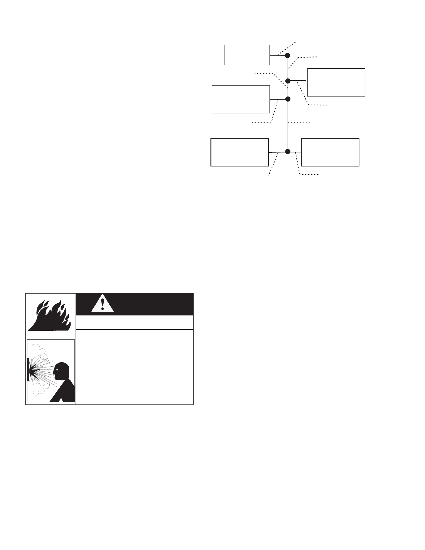
40
CALCULATING GAS LINE SIZE
Gas Meter
Water Heater
199,000 BTU/h
Furnace
120,000 BTU/h
Dryer
35,000 BTU/h
Range
65,000 BTU/h
5' (1.5 m) Length
1-1/4" (32 mm) Pipe size
5' (1.5 m)Length
1-1/4"(32 mm) Pipe size
10' (3 m) Length
3/4” (19 mm) Pipe Size
10' (3 m ) Length
1" (25 mm) Pipe size
10'(3 m)Length
3/4" (19 mm) Pipe size
15' (4.6 m) Length
1" (25 mm) Pipe size
15' (4.6 m) Length
1/2" (25 mm) Pipe size
10' (3 m) Length
1/2" (25 mm) Pipe size
A
B
Figure 45. Gas Sizing Example: Natural Gas
To calculate the gas line size based on the energy content
of 1,000 BTU/Cubic ft, do the following:
1. Divide each appliance's BTU/h requirement by 1,000
BTU/ft
3
to get the appliance's ft
3
/h requirement.
2. Take into account the distance from the appliance to
the gas meter. See Table 19 (page 41) and Table 20
(page 41) to properly size the line.
3. For sections of the gas line supplying gas to more than
one appliance (Ex: Point A to Point B), add up under the
column of 50 ft, Section A to B needs to be 1" in order
to supply 220 cubic ft.
For Example: The section from A to B supplies gas
to the furnace, range and dryer. Adding up the BTU/h
requirements and dividing by 1,000 yields a cubic ft
per hour requirement of 220 cubic ft of gas per hour.
The farthest appliance is the range, which is 50 ft
away from the meter. Looking at the above chart, and
under the column of 50 ft, Section A to B needs to be
1" in order to supply 220 cubic ft.
values; gas pressure above the specied range will cause
dangerous operating conditions and damage to the unit.
Until testing of the main gas line supply pressure is
completed, ensure the gas line to the water heater is
disconnected to avoid any damage to the water heater.
If the gas supply pressure to the heater is greater than the
specied maximum, a eld-supplied regulator is required.
The regulator must lower the gas pressure within the
approved range.
Install the gas regulator according to the manufacturer's
instructions.
The regulator must be sized for the water heater input and
provide the specied pressures that are listed on the rating
plate.
In the absence of minimum install distance, it is recommended
that there is at least 3 ft (1 m) of piping between the regulator
outlet and the water heater's inlet gas connection.
Make sure gas supplied is same type listed on the water
heater’s rating label.
Exposure to higher gas supply pressure may cause damage
to the gas controls which could result in re or explosion. If
overpressure has occurred such as through improper testing
of gas lines or malfunction of the supply system the water
heater’s gas valve must be checked for safe operation by
a Qualied Service Agency.
Ensure supply regulator vent lines and the safety vent valves
are protected against blockage. These are components of
the gas supply system, not the water heater. Vent blockage
may occur during ice storms.
WARNING
Fire and Explosion Hazard
• Turn off all electric power to the water
heater if service is to be performed.
• Turn the manual gas valve located on
the outside of the unit to the off position.
• Failure to follow these steps could lead
to re or explosion, resulting in personal
injury or death.
It is important to guard against gas valve fouling from
contaminants in the gas ways. Such fouling may cause
improper operation, re or explosion. If copper supply lines
are used they must be internally tinned and certied for
gas service.
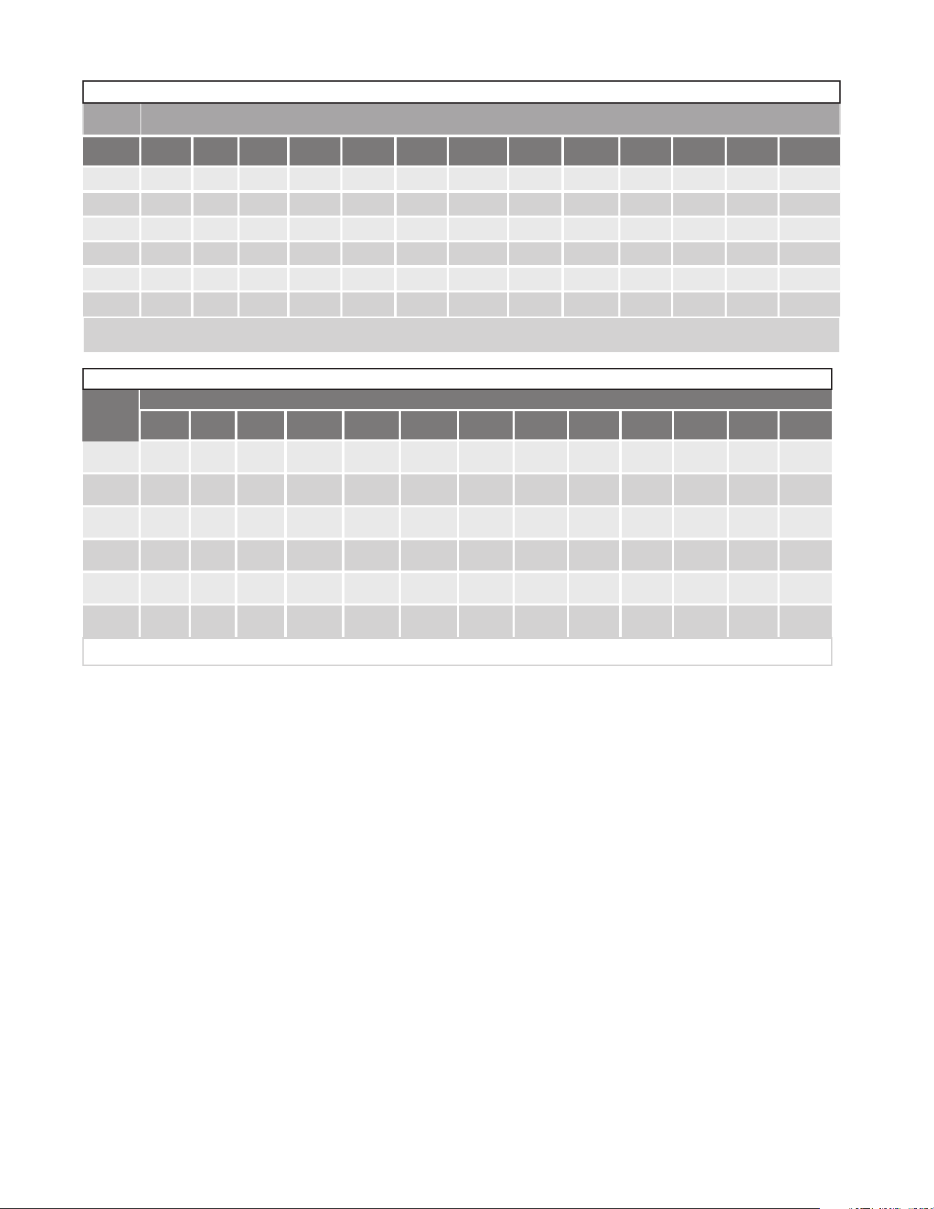
41
The following tables are from NFPA 54.
Table 19. Natural Gas Supply Piping
Pipe
Size
Length
Diameter
10'
(3 .0 m)
20'
(6.1 m)
30'
(9.1 m)
40'
(12.2 m)
50'
(15.2 m)
60'
(18.3 m)
70'
(21.3 m)
80'
(24.4 m)
90'
(27.4 m)
100'
(30.5 m)
125'
(38.1 m)
150'
(45.7 m)
200
(61.0 m)
1/2"
(13 mm)
172 118 95 81 72 65 60 56 52 50 44 40 34
3/4"
(19 mm)
360 247 199 170 151 137 126 117 110 104 92 83 71
1"
(25mm)
678 466 374 320 284 257 237 220 207 195 173 157 134
1 1/4"
(32mm)
1,390 957 768 657 583 528 486 452 424 400 355 322 275
1 1/2"
(38mm)
2,090 1,430 1,150 985 873 791 728 677 635 600 532 482 412
2"
(51mm)
4,020 2,760 2,220 1,900 1,680 1,520 1,400 1,300 1,220 1,160 1,020 928 794
Maximum delivery Capacity in Cubic Feet of Gas per Hour (based on IPS Pipe carrying Natural Gas with 0.60 Specific Gravity with a Pressure Drop of 0.5" W.C.).
Based on Energy Content of 1,000 BTU/Cubic ft: The water heater requires 199 Cubic ft/hr.
Unit: Cubic feet per hour
Table 20. Propane (LP) Supply Piping
Diameter Length
10'
(3 .0 m)
20'
(6.1 m)
30'
(9.1 m)
40'
(12.2 m)
50'
(15.2 m)
60'
(18.3 m)
70'
(21.3 m)
80'
(24.4 m)
90'
(27.4 m)
100
(30.5 m)
125
(38.1 m)
150'
(45.7 m)
200'
(61.0 m)
1/2"
(13 mm)
268 184 148 126 112 101 93 87 82 77 68 62 53
3/4"
(19 mm)
567 393 315 267 237 217 196 185 173 162 146 132 112
1"
(25mm)
1,071 732 590 504 448 409 378 346 322 307 275 252 213
1 1/4"
(32mm)
2,205 1,496 1,212 1,039 913 834 771 724 677 630 567 511 440
1 1/2"
(38mm)
3,307 2,299 1,858 1,559 1,417 1,275 1,181 1,086 1,023 976 866 787 675
2"
(51mm)
6,221 4,331 3,465 2,992 2,646 2,394 2,205 2,047 1,921 1,811 1,606 1,496 1,260
Maximum Capacity of Propane (LP) Based on 11" W.C. supply pressure at a 0.5" W.C. pressure drop.
Unit: kBTU per hour
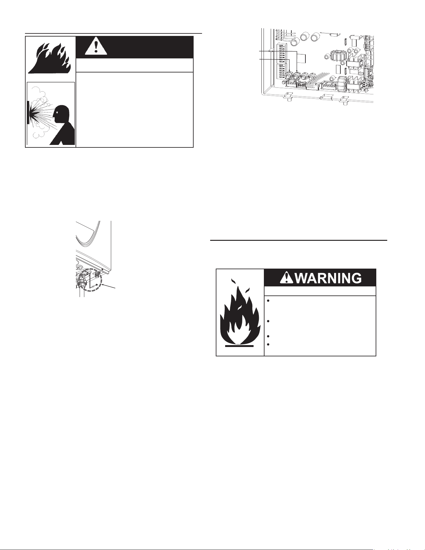
42
MEASURING INLET GAS PRESSURE
WARNING
Fire and Explosion Hazard
• Turn off all electric power to the water
heater if service is to be performed.
• Turn the manual gas valve located on
the outside of the unit to the off position.
• Failure to follow these steps could lead
to re or explosion, resulting in personal
injury or death.
The water heater cannot perform properly without sufcient
inlet gas pressure. Do the following to check the inlet gas
pressure. THIS IS ONLY TO BE DONE BY A LICENSED
PROFESSIONAL.
1. Shut o the manual gas valve on the gas supply line.
2. Remove the screw from the pressure port which is
located on the gas inlet of the water heater shown in
Figure 46.
Pressure
Port
Figure 46. Location of Pressure Port
3. Connect the manometer to the pressure port and zero
Take a reading of the supply dynamic gas pressure with
all gas burning equipment running at maximum
4. Re-open the manual gas valve. Verify that there are no
gas leaks.
5. With all gas burning equipment o, take a reading of the
stac gas pressure and make a note of it.
6. Measure gas supply pressure at minimum heater
operaon as follows:
a. Reduce water flow so the heater is running at
minimal operaon.
b. Press the MIN buon on the computer board. See .
c. Take a supply gas pressure reading and verify that
it is within the specied inlet gas pressure range.
MIN Button
MAX Button
Figure 47. Computer Board
7. Take a reading of the supply dynamic gas pressure with
all gas burning equipment running at maximum rate.
8. The static and dynamic pressures should be within the
ranges specied on the heater's rating plate and Table
4 (page 13) .
The difference of static to dynamic pressure should not
exceed 1.5" W.C. Pressure drops that exceed 1.5" W.C.
can indicate restricted gas ow, undersized gas lines, and/
or undersized supply regulators. (NOTICE: In Canada,
the pressure drops cannot exceed those specied in CSA
B149.1.)
SUPPLY GAS PRESSURE ADJUSTMENT
Supply gas pressure shall be measured while the water
heater is not ring (static pressure) AND while the water
heater is ring at full capacity (dynamic pressure).
Fire and Explosion Hazard
Turn off gas lines during installation.
Contact a qualified installer or service
agency for installation and service.
Excessive gas pressure to gas valve can
cause serious injury or death.
Do not use water heater with any gas
other than the gas shown on the rating
label.
If the supply gas pressure to the water heater is not between
the required minimum and maximum values given in Table
2 (page 10) adjust the supply gas regulator as necessary.
Adjust the supply gas regulator(s) per the regulator
manufacturer’s instructions to achieve the required “static”
and “dynamic” supply gas pressure.
In multiple water heater installations or in installations
where the installed water heater(s) share a common gas
supply main with other gas red appliances; the supply gas
pressures shall be measured at each water heater with all
gas red appliances connected to a common main ring
at full capacity.
43
1. For test pressures exceeding 1/2 psi (3.45 kPa)
disconnect the water heater and its Main Gas Shutoff
Valve from the gas supply piping system during testing,
see Figure 44 (page 39). The gas supply line must
be capped when disconnected from the water heater.
2. For test pressures of 1/2 psi (3.45 kpa) or less, the water
heater need not be disconnected, but must be isolated
from the supply gas line by closing the Main Gas Shutoff
Valve during testing.
3. Paint all supply gas line joints and connections upstream
of the water heater with a rich soap and water solution
to test for leaks. Bubbles indicate a gas leak. Do not use
matches, candles, ame or other sources of ignition for
this purpose.
4. Repair any leaks before placing the water heater in
operation.
PURGING
Gas line purging is required with new piping or systems.
Purging should be performed per the current edition of
NFPA 54 the National Fuel Gas Code or CAN/CSA B149.1
Natural Gas and Propane Installation Code.
ELECTRICAL CONNECTIONS
All electrical work must be installed in accordance with the
National Electrical Code, ANSI/NFPA 70 or the Canadian
Electrical Code, CSA C22.1 and local requirements.
When installed, the water heater must be electrically
grounded in accordance with local codes or, in the absence
of local codes, with the National Electrical Code, ANSI/
NFPA 70 or the Canadian Electrical Code, CSA C22.1.
If any of the original wire as supplied with the water heater
must be replaced, it must be replaced with 105°C rated
wiring or its equivalent, except in the burner housing. In
this case 200°C rated wire must be used.
WARNING
Shock or Electrocution Hazard
• Follow the electrical code requirements
of the local authority having jurisdiction.
In the absence of such requirements,
follow the current edition of the National
Electrical Code ANSI/NFPA 70 in the
U.S. or the current edition of CSA C22.1
Canadian Electrical Code Part 1 in
Canada.
• When servicing or replacing parts within
the water heater, label all wires prior to
disconnection to facilitate an easy and
error-free reconnection. Wiring errors can
cause improper and dangerous operation.
Verify proper operation after servicing.
• Failure to observe these warnings could
result in personal injury or death.
DEDICATED POWER WIRING AND BREAKERS
Dedicated power supply wires, neutral wires, ground wiring,
and dedicated circuit breakers often prevent electrical line
noise and are required when installing the water heater.
On multiple water heater installations the supply gas line
regulators shall be adjusted to provide gas pressure to each
water heater within the minimum and maximum supply
pressure requirements listed in Table 2 (page 10) with
all gas red appliances connected to a common gas main
ring at full capacity.
NOTE: A pressure drop of more than 1.5” W. C. (0.37
kPa) when the Main Burner ignites is an indication of an
inadequate supply of gas and can lead to ignition failure,
rough starts and/or rough operation. If a drop of more
than 1.5” W. C. (0.37 kPa) in supply gas pressure occurs
when the Main Burner ignites, ensure the supply gas lines
and regulator(s) are properly sized and installed. See the
requirements for Power Supply (page 14), Gas Supply
Pressure Requirements (page 13), and Supply Gas
Line Installation (page 39). Ensure all requirements
and installation instructions are maintained.
GAS LINE CONNECTION
1. Install a manual gas shutoff valve between the water
heater and the gas supply line.
2. When the gas connections are completed, it is necessary
to perform a gas leak test either by applying soapy water
to all gas ttings and observing for bubbles or by using
a gas leak detection device.
• The water heater and its individual shutoff valve must
be disconnected from the gas supply piping system
during any pressure testing of that system at test
pressures in excess of 1/2 psi (3.5 kPa).
• The water heater must be isolated from the gas supply
piping system by closing its individual manual shutoff
valve during any pressure testing of the gas supply
piping system at test pressures equal to or less than
1/2 psi (3.5 kPa).
3. Always purge the gas line of any debris and/or water
before connecting to the gas inlet.
NOTE: If overheating occurs or the gas supply fails to shut
off, turn off the Main Gas Shutoff valve to the water heater.
GAS LINE LEAK TESTING
Any time work is done on the gas supply system perform a
leak test to avoid the possibility of re or explosion.
Fire and Explosion Hazard
Leak test gas connections before
placing water heater in operation.
Disconnect gas piping at main
gas shutoff valve before leak
testing heater.
Install sediment trap in
accordance with NFPA 54 or
CAN/CSA B149.1.
Use joint compound or Teflon tape
compatible with propane gas.
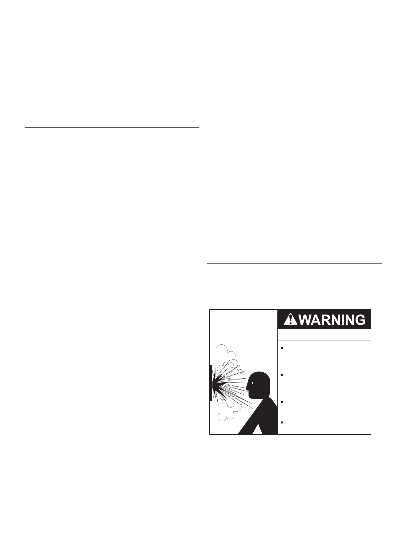
44
THERMOMETERS (NOT SUPPLIED)
Thermometers are installed in the water piping system as a
means of detecting the temperature of the hot water supply
at critical points in the system. Field-supplied thermometers
should be obtained and installed. See Water Piping
Diagrams (page 66).
WATER (POTABLE) HEATING AND SPACE HEATING
1. All water piping components connected to the water
heater that are for space heating applications shall be
suitable for use with potable water.
2. Toxic chemicals, such as those used for boiler treatment,
must NEVER be introduced into this system.
3. The water heaters covered in this manual may never
be connected to any existing heating system or
component(s) previously used with non-potable water
heating appliance.
4. When the system requires water for space heating that
exceed safe temperatures at domestic water xtures
a mixing valve must be installed. See Mixing Valves
(page 14).
Note: Malfunctions caused by the power supply and
costs to install power supply lters are not covered
under the limited warranty. See the Commercial
Water Heater Limited Warranty provided with this
water heater.
5. These water heaters cannot be used in space heating
applications only.
T&P VALVE DISCHARGE PIPE
This water heater is provided with a properly rated/sized
and certied combination temperature - pressure (T&P)
relief valve by the manufacturer. Water Line Connections
(page 44) and Water Piping Diagrams (page 66) for
information on replacement and other requirements.
Explosion Hazard
Temperature-Pressure Relief Valve
must comply with ANSI Z21.22-
CSA 4.4 and ASME code.
Properly sized temperature-
pressure relief valve must be
installed in opening provided.
Can result in overheating and
excessive tank pressure.
Can cause serious injury or death.
NOTE: This water heater should not be connected to an
electrical supply with a Ground Fault Circuit Interrupter
(GFCI) or Arc Fault Circuit Interrupter (AFCI) with Integral
GFCI protection as dened in NFPA 70, CSA C22.1 and
UL 943.
POWER SUPPLY CONNECTIONS
Read the requirements for the Power Supply (page 14)
before connecting power.
Note: The water heater comes with a power plug instead
of a junction box.
WATER LINE CONNECTIONS
The water piping installation must conform to these
instructions and to all local and national code authority
having jurisdiction. Good practice requires that all heavy
piping be supported.
Read and observe all requirements in the following sections
before installation of the water piping begins:
1. Mixing Valves (page 14).
2. Note: Malfunctions caused by the power supply and
costs to install power supply lters are not covered under
the limited warranty. See the Commercial Water Heater
Limited Warranty provided with this water heater.
3. Dish-washing Machines (page 15).
4. Water Line Connections (page 44).
5. Thermal Expansion and Closed Water Systems (page
15)
6. For multiple water heater installations see Water Piping
Diagrams (page 66).
WATER PIPING DIAGRAMS
This manual provides detailed water piping diagrams for
typical methods of application for the water heaters, see
Water Piping Diagrams (page 66).
The water heater may be installed with or without a separate
storage tank. When used with a separate storage tank,
the circulation may be either by gravity or by means of a
circulating pump. When a circulating pump is used, it is
important to note that the ow rate should be slow so that
there will be a minimum of turbulence inside the water
heater storage tank.
Adjust ow by throttling a full port ball valve installed in the
circulating line on the outlet side of the pump. Never throttle
ow on the suction side of a pump. See the Water Piping
Diagrams (page 66).
NOTE: In addition to the factory installed Temperature-
Pressure Relief valve (T&P valve) on the water heater, each
remote storage tank that may be installed and piped to a
water heating appliance must also have its own properly
sized, rated and approved Temperature-Pressure Relief
valve installed.
Call the toll free technical support phone number listed on
the back cover of this manual for further assistance in sizing
a T&P valve for remote storage tanks.

45
Water Damage Hazard
Temperature-Pressure Relief Valve discharge
pipe must terminate at adequate drain.
•
CAUTION
Install a discharge pipe between the T&P valve discharge
opening and a suitable oor drain. Do not connect discharge
piping directly to the drain unless a 6” (15.2 cm) air gap is
provided. To prevent bodily injury, hazard to life, or property
damage, the relief valve must be allowed to discharge water
in adequate quantities if circumstances demand. If the
discharge pipe is not connected to a drain or other suitable
means, the water ow may cause property damage.
T&P Valve Discharge Pipe Requirements:
• Shall not be smaller in size than the outlet pipe size
of the valve, or have any reducing couplings or other
restrictions.
• Shall not be plugged or blocked.
• Shall not be exposed to freezing temperatures.
• Shall be of material listed for hot water distribution.
• Shall be installed so as to allow complete drainage of
both the Temperature-Pressure Relief Valve and the
discharge pipe.
• Must terminate a maximum of six inches above a oor
drain or external to the building. In cold climates, it is
recommended that the discharge pipe be terminated at
an adequate drain inside the building.
• Shall not have any valve or other obstruction between
the relief valve and the drain.
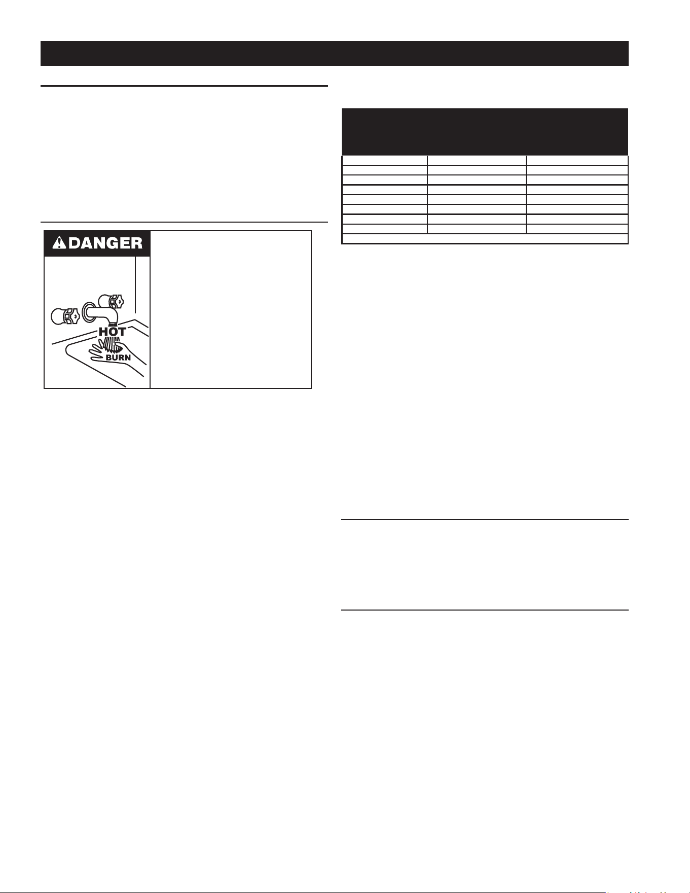
46
HIGH TEMPERATURE LIMIT CONTROL (ECO)
This water heater is equipped with a non adjustable high
temperature limit switch. The switch is a normally closed
switch that opens (activates) on a rise in temperature.
If the switch activates (contacts open) due to abnormally
high water temperatures water heating unit, the control
system will immediately close the gas valve and end the
current heating cycle. The control system will "lock out"
disabling further heating operation.
THERMOSTAT CONTROL
Water temperature over 125°F (52°C)
can cause severe burns instantly
resulting in severe injury or death.
Children, the elderly and the
physically or mentally disabled are at
highest risk for scald injury.
Feel water before bathing or
showering.
Temperature limiting devices such as
mixing valves must be installed
when required by codes and to
ensure safe temperatures at fixtures.
Hot water temperatures required for automatic dishwasher
and laundry use can cause scald burns resulting in serious
personal injury and/or death. Table 21 (page 46) shows
the approximate time-to-burn relationship for normal adult
skin.
The temperature at which injury occurs varies with the
person’s age and duration of exposure. The slower
response time of children, the elderly or disabled persons
increases the hazards to them. If anyone using hot water
provided by the water heater being installed ts into one of
these groups or if there is a local code or state law requiring
a certain water temperature at the point of use, then special
precautions must be taken.
In addition to using the lowest possible temperature setting
that satises the demand of the application a mixing valve
can be installed at the water heater or at the hot water taps
to further reduce system water temperature. See Figure 7
(page 15).
Never allow small children to use a hot water tap or draw
their own bath water. Never leave a child or disabled person
unattended in a bathtub or shower.
The water heater should be located in an area where the
general public does not have access to set temperatures.
Setting the Operating Set Point at 120°F (49°C) will reduce
the risk of scalds. Some States require settings at specic
lower temperatures.
Table 21. Time/Temperature to Burn
Water Temperature
°F (°C)
Time for 1st Degree
Burn
(Less Severe Burns)
Time for Permanent
Burns
2nd & 3rd Degree
(Most Severe Burns)
110 (43) (normal shower temp.)
116 (47) (pain threshold)
116 (47) 35 minutes 45 minutes
122 (50) 1 minute 5 minutes
131 (55) 5 seconds 25 seconds
140 (60) 2 seconds 5 seconds
149 (65) 1 second 2 seconds
154 (68) instantaneous 1 second
(U.S. Government Memorandum, C.P.S.C., Peter L. Armstrong, Sept. 15, 1978)
The water heaters covered in this manual are equipped
with an electronic control system to regulate water
temperature inside the storage tank. The control system
uses temperature sensors installed in the tank and in the
water heating unit.
There are two factory-installed temperature probes in the
storage tank that help the pump controller determine when
to run the pump. One is installed in the top of the storage
tank and one installed near the bottom. The controller learns
the approximate set point for controlling the pump and there
is no need to adjust the set point manually.
There are four temperature sensors in the water heating
unit that monitor the water temperature at various points
within the unit and the temperature of the exhaust gas. The
water heating unit computer uses the sensor information to
modulate the gas and water valves to ensure proper output
water temperature and hot water outows.
FIRING RATE MODULATION
The water heating unit controller regulates the ring rate
to achieve the target temperature setpoint. The ring rate
is dictated by the hot water draw, proximity to the tank
temperature setpoint, and various other temperature
limitations.
HIGH TEMPERATURE APPLICATIONS
Higher operating temperatures cause more wear on all
water heaters and will decrease the life span of the water
heater. Consider installing a small booster water heater
for high temperature applications, such as commercial
dishwashers, to raise the outlet temperature from the
larger primary water heater to the desired point-of-use
temperature.
Contact your local distributor or call the technical support
phone number listed on the back cover of this manual for
further technical assistance.
TEMPERATURE REGULATION
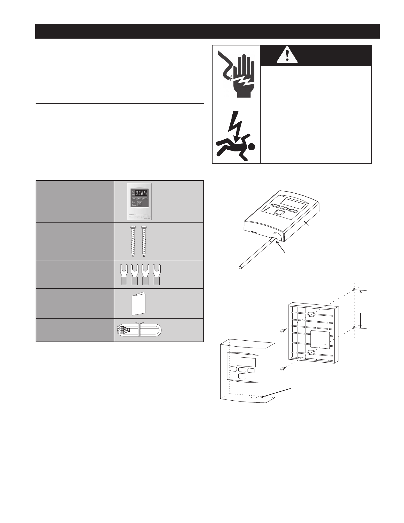
47
WARNING
Shock or Electrocution Hazard
• This remote controller is NOT waterproof.
• The water heater can only have one
remote controller.
• Do not install in high temperature
environments, high humidity conditions
outdoors, in direct sunlight, or within the
reach of children.
• Make sure the remote controller does not
come into contact with water or oil.
• Failure to observe these warnings could
result in personal injury or electrical
shock.
MOUNTING AND WIRING THE REMOTE CONTROLLER
1. Take off the Back plate from the remote controller with
a at head screwdriver.
Insert a flat head screwdriver
in one of the slots at the
bottom of the unit and twist.
Main body
Figure 48. Removing the Cover
Remove cable
access cut-out
with pliers.
3-1/4”
Figure 49. Attaching the Back Plate
2. Attach the Back plate to the wall with the two provided
screws. (Fig. B)
3. If you use another cable, crimp the Fork terminals to
the wires.
The water heaters covered in this manual are equipped
with an electronic control system that regulates water
temperature inside the storage tank. Heating cycles and
ignition are managed by the control system. The high-limit
switch, ame sensor, pressure switches, and temperature
probes are monitored by the control system.
TEMPERATURE REMOTE CONTROLLER
Included Accessories
The remote control is an optional accessory that can be
installed in a hall, closet, etc., to allow for temperature
adjustment without having to go to the heater.
When installed, the remote will take priority over the built-in
controller.
Verify that the items listed below are included with the
remote controller.
Remote Temperature Control
Qty. 1
Screws
Qty. 2
Fork Terminals
Qty. 4
Manual
Qty. 1
Remote Control Cable
Qty. 1
100209924 (TM-RE42)
It is also an optional accessory as a second remote. *The
optional remote controller (sold separately) has no remote
controller cable.
INSTALLATION
Do not place the remote controller cable close to other wires
from other products.
Cables used for the remote controller connection must be:
• Minimum 20 gauge wire (No polarity)
• Maximum 400 ft (122 m) long
CONTROL SYSTEM OPERATION
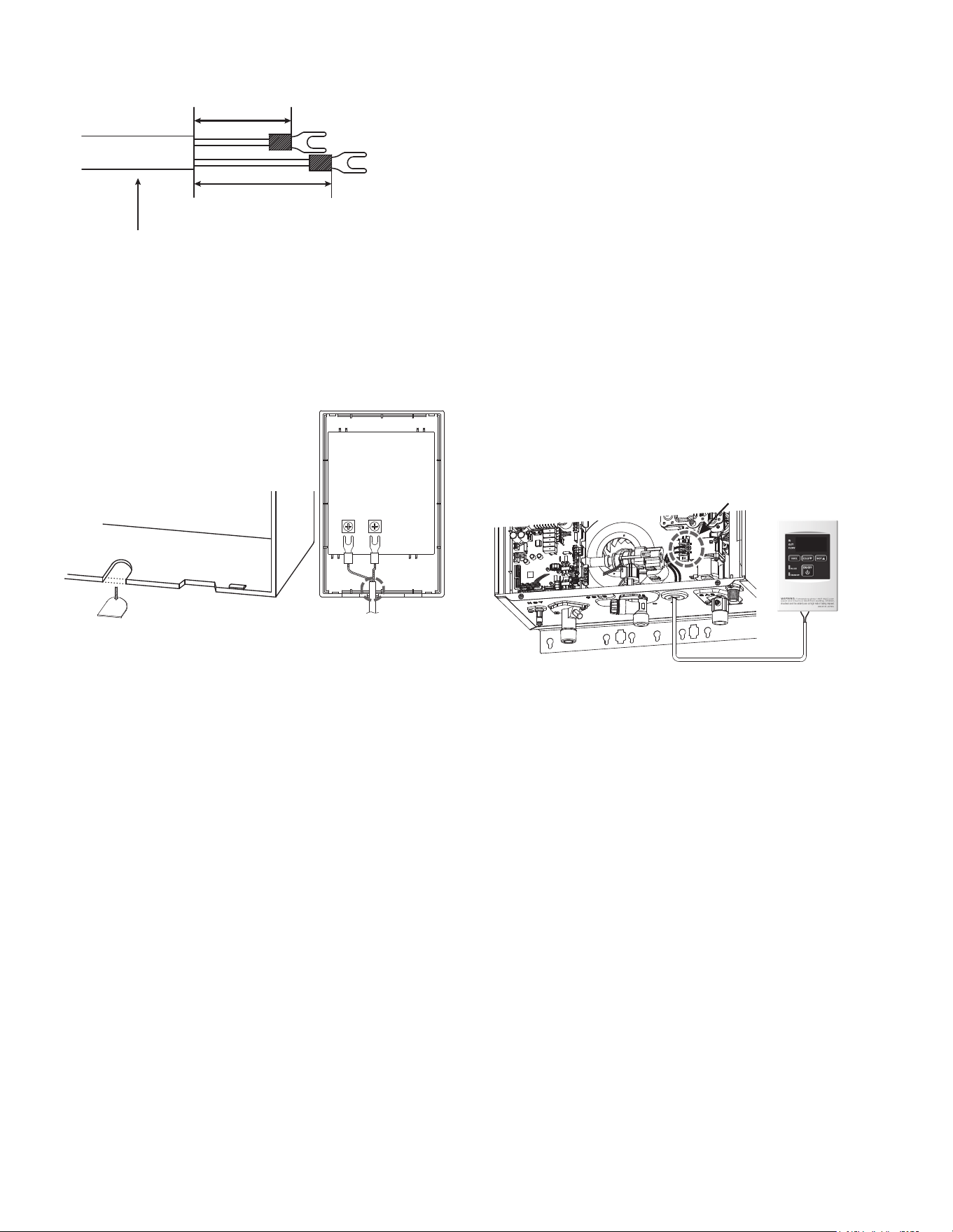
48
1-3/8 Inch (35 mm)
1-5/8 Inch (41 mm)
Fork
Terminals
Remote controller cable
Figure 50. Remote Cable Fork Terminals
4. Tighten the two Fork terminals beneath the two remote
controller terminal screws on the back of the controller.
5. Remove the cable access cut out from the bottom of
the controller.
6. Place the Main body back on the Back plate, with the
Remote controller cable running out of the bottom inlet.
See Figure 51.
Cable Access Cut-Out
Figure 51. Cable Access Cut-Out and Terminal Connection
CONNECTING THE REMOTE CONTROLLER TO THE WATER
HEATER
1. Disconnect power supply from the water heater.
2. Take off the water heater’s front cover.
3. Locate the two terminals for the remote controller in the
water heater. (Refer to Figure 51.)
4. Take off the back plate from the remote controller, and
then attach the two fork terminals to the connector base
on the back side of the remote controller with two screws.
Make sure the terminals are rmly xed. (See the above
instructions for installation of the remote controller.)
5. Pull the remote controller cable through the hole at the
bottom of the water heater’s casing.
6. Secure both controller cable terminals to the terminals
on the computer board as shown below. (Secure them
underneath the screw terminals. No polarity.)
* Do NOT jump or short-circuit the cables, or
computer will be damaged.
7. Replace the front cover securely.
Connect other end
to these terminals
100209924
(TM-RE42)
Figure 52. Remote Controller Connection to Water Heating
Unit

49
PRIOR TO START UP
Installation and start up of this water heater requires abilities
and skills equivalent to that of a licensed tradesman in the
eld involved. See Qualications (page 6).
DO NOT USE THIS APPLIANCE IF ANY PART HAS
BEEN EXPOSED TO FLOODING OR WATER DAMAGE.
Immediately call a qualied service agency to inspect the
appliance and to make a determination on what steps should
be taken next. If the unit is exposed to the following, do not
operate heater until all corrective steps have been made
by a qualied service agency.
1. External re
2. Damage
3. Firing without water
Light the water heater in accordance with the Lighting and
Operation Instruction label on the water heater and in this
manual Lighting the Water Heater (page 50).
The water heaters covered by this manual are equipped
with an electronic control system, which automatically
sequences the Combustion Blower, pre and post purging
of the combustion chamber, the spark transformer, the 24-
volt gas valve, Main Burner ignition, and ame sensing. The
control system will lock out after three unsuccessful ignition
attempts. See Control System Operation (page 47).
START-UP PREPARATION
Before attempting start up, ensure the water heater is
properly grounded. Flame sensing requires an adequate
earth ground. If the water heater is not properly grounded
it will cause Ignition Failure. See Electrical Connections
(page 54).
Be certain that the water heater is full of water, that air is
purged from the gas and water lines and that there are
no leaks in the gas and water lines. Ensure all inlet water
valves are open.
FILLING THE WATER HEATER STORAGE TANK
Follow these steps to ll the water heater prior to start up.
1. Close the storage tank drain valve.
2. Open a nearby hot water faucet to permit air in system
to escape.
3. Fully open the cold water inlet valve allowing the piping
and storage tank to ll with water.
4. Close the hot water faucet opened in Step 2 as water
starts to ow from the faucet.
The water heater pump and piping is below the water level of
the lled storage tank and gravity ensures that the water lls
the piping and pump. It is not necessary to prime the pump.
In the unlikely event that the pump piping becomes blocked,
a ow sensor detects the problem and prevents the water
heating unit from ring without water.
INITIAL OPERATION
FOR YOUR SAFETY, READ BEFORE OPERATING
1. Check the GAS and WATER CONNECTIONS for leaks
before ring unit for the rst time.
2. Open the main gas supply valve to the unit using only
your hand to avoid any spark. Never use tools. If the
knob will not turn by hand, do not try to force it; call a
qualied service technician. Forced repair may result in
a re or explosion due to gas leaks.
3. Be sure to check for the presence of leaking gas toward
the bottom of the unit because some gases are heavier
than air and may settle towards the oor.
4. Measure the Static Supply Gas Pressure. See
Measuring Inlet Gas Pressure (page 42).
5. Confirm that the measurement is within operating
parameters. See Table 4 (page 13).
6. Adjust the pressure if necessary. See Supply Gas
Pressure Adjustment (page 42).
7. Do not try to light the burner manually. It is equipped
with an electronic ignition device which automatically
lights the burner.
8. Check for PROPER VENTING and combustion air to
the water heater.
9. Purge the GAS and WATER LINES to remove any air
pockets.
10. Do not use this appliance if any part has been under
water. Immediately contact a qualied installer or service
agency to replace a ooded water heater. Do not attempt
to repair the unit! It must be replaced!
FLOW RATES
The following are the minimum ow rates:
• Flow rate to activate the water heater: 0.5 gallon per
minute at the default set temperature (1.9 L/min).
• Flow rate to keep the water heater running: 0.4 gallon
per minute (1.5 L/min).
START UP
50
LIGHTING THE WATER HEATER
The instruction label below is afxed to the water heaters that are covered by this manual at the factory and must be
followed when lighting and operating the water heater.
WARNING: If you do not follow these instructions exactly, a fire or explosion may result causing
property damage, personal injury or loss of life.
A. This appliance does not have a pilot. It is equipped with an ignition device which automatically lights the
burner. Do not try to light the burner by hand.
B. BEFORE OPERATING smell all around the appliance area for gas. Be sure to smell next to the oor
because some gas is heavier than air and will settle on the oor.
WHAT TO DO IF YOU SMELL GAS
• Do not try to light any appliance.
• Do not touch any electric switch; do not use any phone in your building.
• Immediately call your gas supplier from a neighbor’s phone. Follow the gas supplier’s instructions.
• If you cannot reach your gas supplier, call the re department.
C. Use only your hand to turn the gas shutoff valve. Never use tools. If the valve will not turn by hand, don’t
try to repair it, call a qualied service technician. Force or attempted repair may result in a re or explosion.
D. Do not use this appliance if any part has been under water. Immediately contact a qualied installer or
service agency to replace a ooded water heater. Do not attempt to repair the unit! It must be replaced!
1. STOP! Read the safety information above on this label.
2. Turn off all electric power to the appliance.
3. Do not attempt to light the burner by hand.
4. Turn the gas shutoff valve located on the outside of the unit to the closed position.
5. Wait ve (5) minutes to clear out any gas. If you then smell gas, STOP! Follow “B” in the safety information
above on this label. If you don’t smell gas, go to the next step.
6. Turn the gas shutoff valve located on the outside of the unit to the open position.
7. Turn on all electrical power to the appliance.
8. If the appliance will not operate, follow the instructions in “To Turn Off Gas to Appliance,” and call your
service technician or gas supplier.
1. Turn off all electric power to the appliance if service is to be performed.
2. Turn the gas shutoff valve located on the outside of the unit to the closed position.
FOR YOUR SAFETY READ BEFORE OPERATING
OPERATING INSTRUCTIONS
TO TURN OFF GAS TO APPLIANCE
51
A pressure relief valve listed as complying with the standard for Relief Valve and Automatic Gas
Shutoff Devices for Hot Water Supply System, ANSI Z21.22 • CSA 4.4, shall be installed at the
time of installation of the water heater in the location specied by the manufacturer. Local codes
shall govern the installation of relief devices for safety operation of the water heater. The relief valve
must not be removed or plugged.
No valve shall be placed between the relief valve and the water heater. The relief from the discharge
of the pressure relief valve shall be disposed of in a suitable place where it will cause no damage.
Also, there shall be no other reducing coupling or other restrictions installed on the discharge line
to restrict ow.
Vapors from ammable liquids will explode and catch re causing death or severe burns.
Do not use or store ammable products such as gasoline, solvents or adhesives in the same
room or area near the water heater.
Keep ammable products:
1. Far away from heater.
2. In approved containers.
3. Tightly closed and out of reach of children.
4. Water heater has a main burner, which may
come on at any time and will ignite ammable
vapors.
Vapors:
1. Cannot be seen.
2. Are heavier than air.
3. Go a long way on the oor.
4. Can be carried from other rooms to the main
burner by air currents.
Do not install water heater where ammable products will
be stored or used unless the main burner is at least 18”
above the oor. This will reduce, but not eliminate the risk
of vapors being ignited by the main burner.
Read and follow water heater warnings and instructions. If the owner’s
manual is missing, contact the retailer or manufacturer.
Flammable Vapors
FLAMMABLES-
1. Water temperature over 125°F (52°C) can cause severe burns instantly or death from scalds.
2. Children, disabled and elderly are at highest risk of being scalded.
3. Feel water before bathing or showering.
4. Temperature limiting valves are available. See manual.
5. The outlet temperature of the water heater is set at 120°F (50°C). If you require
water temperatures below this setting, follow the instruction manual.
6. Use this heater at your own risk. Test the water before bathing or showering. Do not leave children
or an inrm person unsupervised. See your local water supply company [plumbing hardware
retailer] for temperature limiting valves that are available.
BURN
HOT
HOT
DANGER
DANGER
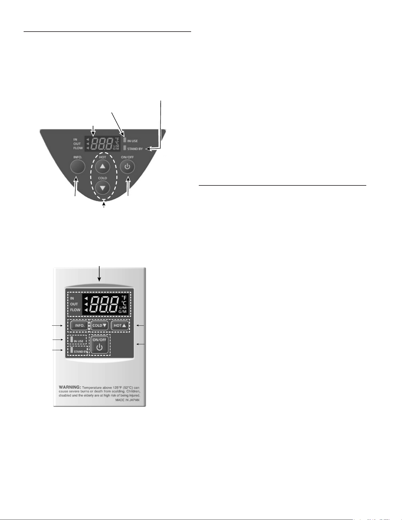
52
NORMAL OPERATION
The water heater has a built-in control panel on the side of
the unit. You can also order the remote controller for use with
the water heater. If you use the remote control, temperature
and ow settings you set take precedence over the built-in
control panel.
When the water heater is connected with the remote
controller, the built-in controller will not operate temperature
settings. It will only work for the information mode.
Temperature
and Flow Display
In Use
LED
Stand By
LED
On/O ButtonInfo Button
Hot/Cold Temperature
Control
Figure 53. Built-In Control Panel
The controller has an energy saving mode. Five minutes
after the water heater stops operating, the backlight of the
controller turns off. The backlight of the remote will turn back
on once the water heater begins ring again.
Temperature and Flow Display Screen
Info Button
In Use
Indicator
Stand By
Indicator
On/Off Button
Hot/Cold Temperature
Control Buttons
Figure 54. Remote Controller
The built-in control panel and the remote controller have the
same indicators and buttons, although they are arranged
differently.
• Temperature and Flow Display - runs in three display
modes: Inlet Temperature, Outlet Temperature, and
Water Flow. Switch between modes by pressing the
Info button.
• Info Button - Switches the display among the three
display modes: Inlet Temperature, Outlet Temperature,
and Water Flow.
• In-Use Indicator - lights up when the burner is running.
• Stand By Indicator - indicates that the power is on.
• Hot and Cold Temperature Control Buttons - increase
or decrease the temperature settings for the Outlet
temperature setting.
• On/Off Button - Turns power to the controller on and off.
This effectively enables and disables the water heating
function, but the power to the water heater stays on.
SETTING THE OUTLET WATER TEMPERATURE
In general, you set the outlet temperature using the HOT
and COLD buttons, but a two-button safety sequence is
required to increase the temperature from 120 °F (50 °C)
to 125 °F (52 °C) and from 140 °F (60 °C) to 145 °F (63
°C). This is to prevent setting the outlet temperature too
high unintentionally.
1. Turn on the 120 VAC power supply to the unit (the water
heater or the mul-unit controller).
2. Press the "ON/OFF" button on the controller in order to
turn the controller on.
When ON, the STAND BY LED is lit. It shows the set
temperature on its display as shown in the picture on
the right. (EX.: 120 °F)
3. Press the "HOT" button to increase the temperature or
the "COLD" button to decrease the temperature setting
of the unit.
To increase the temperature from 120 °F (50 °C)
to 125 °F (52 °C):
a. Press the "HOT" button to increase the temperature
up to 120 °F (50 °C).
b. Press and hold the "INFO" button and the "HOT"
button for at least 3 seconds. The display will ash
and change to 125 °F (52 °C).
c. Press the "HOT" button to increase the temperature
from 125 °F (52 °C) to 140 °F (60 °C).
To increase the temperature above 140 °F (60 °C):
a. Press the "HOT" button to increase the temperature
up to 140 °F (60 °C).
b. Press and hold the "INFO" button and the "HOT"
button for at least 3 seconds. The display will ash
and the temperature will change to 145 °F (63 °C)
c. Press the "HOT" button to set the temperature above
145 °F (63 °C) up to 185 °F (85 °C) .
The following are the possible settings for the outlet
temperature:
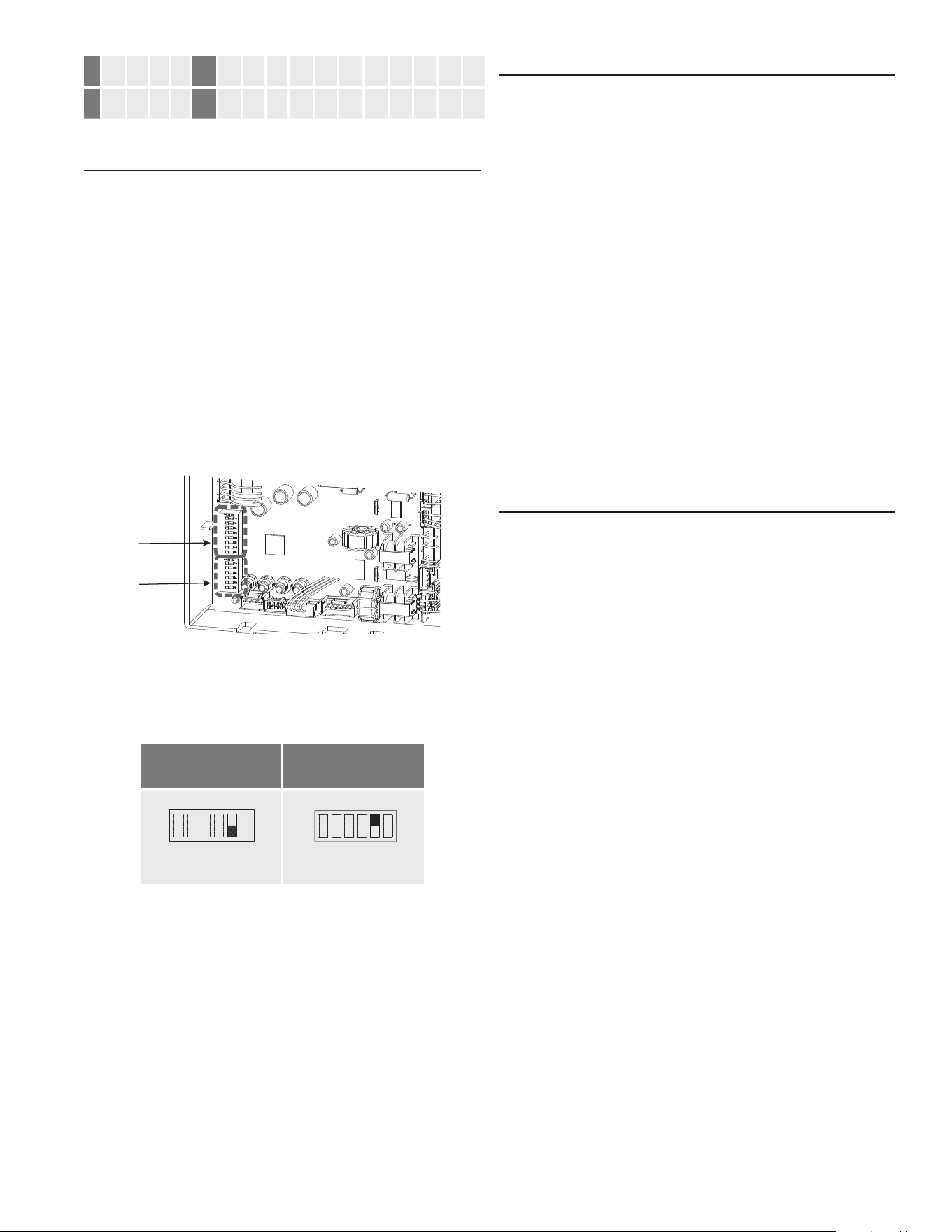
53
°F 100 105 110 115 120* 125 130 135 140 145 150 155 160 165 175 185
°C 38 40 43 45 50* 52 55 57 60 63 65 68 70 75 80 85
Factory Setting (Default): 120 °F (50 °C).
DEFAULT OUTLET TEMPERATURE
The factory setting for the default outlet temperature is
120 °F (50 °C) but you can set it to either 120 °F (50 °C)
or 140 °F (60 °C) by changing the DIP switch settings on
the computer board.
When the remote controller is in normal operation, the set
temperature of the remote controller is given priority over
the set temperature of the DIP switch settings.
To change the default outlet temperature, do the following:
1. Disconnect power supply from the water heater.
2. Take off the water heater’s upper front cover.
3. Locate the computer board in the unit case. See Figure
3 (page 8).
4. Remove the computer board cover.
5. Locate the lower bank DIP switches on the computer
board.
Upper DIP
Switch
Bank
Lower DIP
Switch Bank
Figure 55. Location of DIP Switches
6. On the lower DIP switch bank, note the position of DIP
Switch 5.
Table 22. DIP Switch Settings for Default
Outlet Temperature
120 °F (50 °C)
DEFAULT
140 °F (60 °C)
OFF
ON
1 2 3 4 5 6
No. 5 : OFF
OFF
ON
1 2 3 4 5 62 3 4 5 6
No. 5 : ON
NOTE: The dark squares indicate the position of the
DIP switch.
7. Use a pencil or screw driver to ip Switch 5 to the position
corresponding to the default outlet temperature setting
you want. Do not ip or disturb any other DIP switches.
8. Replace the computer board cover.
9. Replace the water heater's upper front cover.
10. Reconnect the power supply to the water heater.
SETTING UNITS OF MEASURE
You can specify whether you want the water heater to
display temperatures and ow rates in terms of Imperial or
Metric units. The Imperial units are Fahrenheit degrees
(°F) for temperature and gallons per minute (gpm) for ow.
The Metric units are Celsius degrees (°C) for temperature
and liters per minute (lpm) for ow.
Do the following to switch between the two unit systems:
1. Press the "ON/OFF" button on the controller in order to
turn the controller on. When ON, the orange LED is lit.
2. The Temperature and Flow Display screen shows the
current temperature setting for Outlet Temperature. You
can tell which unit system is set by noting whether the
temperature setting is in Celsius degrees or Fahrenheit
degrees.
3. To switch to the other unit system, press and hold the
"INFO" button for at least 3 seconds.
4. The set temperature should now be displayed in the
alternate unit of measurement.
Note: When the water heater is connected to the remote
controller, the built-in controller will not operate temperature
settings. It will only work for the information mode.
FREEZE PROTECTION SYSTEM
This water heater comes equipped with heating blocks to
protect it from damage associated with freezing. When
the freeze protecon thermostat senses air temperature
below 36.5 °F (2.5 °C), the blocks will heat up to prevent
freezing of the unit.
To operate these freeze protection systems, there has to be
electrical power to the unit. Damage to the heat exchanger
caused by freezing temperatures due to power loss is not
covered under the warranty. In cases where power losses
can occur, consider the use of a backup power supply.
The manufacturer also highly recommends the use of
a back-ow preventer (sold separately) to minimize the
amount of cold air entering through the exhaust venting
when the water heater is off.
It is the installer’s responsibility to be aware of freezing issues
and take all preventative measures. The manufacturer will
not be responsible for any damage to the heat exchanger
as a result of freezing.
If you will not be using your heater for a long period of time,
do the following:
1. Completely drain the water out of the unit. See Draining
the Water Heating Unit (page 62).
2. Disconnect power to your heater.
This will keep your unit from freezing and being damaged.
54
ELECTRICAL CONNECTIONS
1. Ensure the power supply connections to the water heater
are polarity correct. See the requirements for the Power
Supply (page 14) and Electrical Connections (page
43).
2. Ensure the water heater is properly grounded. Flame
sensing requires an adequate earth ground. If the water
heater is not properly grounded it will cause Ignition
Failure.
OPERATIONAL PROBLEMS
Read and understand this instruction
manual and the safety messages
herein before installing, operating or
servicing this water heater.
Failure to follow these instructions and
safety messages could result in death
or serious injury.
This manual must remain with the
water heater.
This section of the manual is intended to be an aid in
correcting common operational problems, it is not all
inclusive. The installer may be able to observe and correct
certain problems which might arise when the water heater is
rst put into operation or when it is re-red after a prolonged
shutdown. However, only qualified service agents, as
dened in Qualications on page 6, using appropriate
test equipment, should perform any service procedures on
the water heater.
NOTE: Call the technical support phone number listed on
the back cover of this manual for further technical assistance
or to locate a qualied service agent in your area.
INSTALLATION ERRORS
Operational problems on new installations are often the
result of installation requirements that have been overlooked
rather than failed components. IE: A "Low Gas Pressure"
Fault condition is most often caused by low supply gas
pressure rather than a defective Low Gas Pressure switch.
Rough starting and rough operation are often caused by
undersized supply gas lines and/or the absence of a supply
gas regulator at the water heater.
Prior to performing any operational checks inspect the water
heater installation to ensure all installation requirements
and instructions have been maintained and followed. See
the Installation Checklist (page 54).
NOTE: Costs to correct installation errors are not covered
under the limited warranty. See the Commercial Water
Heater Limited Warranty provided with this water heater.
TROUBLESHOOTING
INSTALLATION CHECKLIST
The list below represents some of the most critical
installation requirements that, when overlooked, often result
in operational problems, down time and needless parts
replacement. This is not a complete list. Before performing
any troubleshooting procedures use the list below to check
for installation errors.
Note: Costs to correct installation errors are not covered
under the limited warranty. See the Commercial Water
Heater Limited Warranty provided with this water heater.
Ensure all installation requirements and instructions in this
manual have been maintained and followed.
WATER HEATER LOCATION
1. Ensure proper clearances to combustibles are maintained
and there is sufcient room to service the water heater.
See Clearance To Combustible Materials (page 11).
2. Ensure the area is free of corrosive elements and
ammable materials. See the instructions in Combustible
Material Storage (page 17).
VENTING
1. Ensure the intake air and/or vent (exhaust) piping is the
correct size for the installed length. See Ventilation
Requirements (page 18).
2. Ensure the maximum equivalent feet of pipe has not
been exceeded for the intake air and/or vent pipe. See
Table 7 (page 21).
3. Ensure the maximum number of elbows has not been
exceeded in the intake air and/or vent pipe. See Table
7 (page 21).
4. Ensure the intake air screen has been removed from the
intake air connection on the water heater when installing
the water heater in a Direct Vent conguration. See
Direct Vent Installations (page 22).
5. Ensure all exterior clearances for the intake air, vent,
and concentric terminations are maintained. See Figure
17 (page 22), Concentric Termination Installation
(page 29) These clearances and those cited by local
and national codes must be maintained.
GAS SUPPLY AND PIPING
1. Ensure a supply gas regulator has been installed for
each water heater. See the requirements for a Power
Supply (page 14).
2. Ensure the supply gas line to each water heater
meets the minimum supply gas line size requirements.
See the requirements for the Gas Supply Pressure
Requirements (page 13) and the installation
instructions in Gas Line Sizing (page 39) and Supply
Gas Pressure Adjustment (page 42).
CONDENSATE DRAIN
Ensure there is a proper condensate drain tube connected
to the water heating unit
55
• See the list of possible causes and things to check and
repair for the Ignition Failure Fault message in Water
Heating Unit Controller Fault and Alert Conditions
(page 56).
• Debris clogging/blocking the intake air screen(s) .
• Debris clogging/blocking the Main Burner - see Figure
3 (page 8).
NOT ENOUGH OR NO HOT WATER
• No power to the water heater, check breaker and fuses.
• Hot water supply valve(s) to xtures closed.
• Operating Set Point is set too low. See Control System
Operation (page 47).
• Ensure there is not any external supervisory control
disabling heating operation.
• The heating capacity of the water heater has been
exceeded, the water heater is unable to meet demand.
• Colder incoming water temperature lengthening the time
required to heat water to desired temperature.
• Hot water piping leaks, open faucets, water heater drain
valve leaking or open.
• Sediment or lime scale accumulation may be affecting
water heater operation. See Maintenance on page 61
for sediment and lime scale removal procedures.
• Water heater not firing at full input rating. Check
actual ring rate of the water heater, see instructions
in Freeze Protection System (page 53). Note that
the water heaters covered by this manual are capable
of modulating their ring rate. The ring rate is dictated
by the hot water draw and various other temperature
limitations.
WATER IS TOO HOT
• Operating Set Point is set too high.
• If installed, check Thermostatic Mixing Valve settings.
• Improper water piping - see Water Piping Diagrams
(page 66).
NOISY OPERATION
• Sediment or lime scale accumulations can cause
rumbling and pounding noises during heating cycles.
See Maintenance (page 61) for sediment and lime
scale removal procedures.
• Normal operating noise of electrical components;
Combustion Blower, transformer hum, relay contact
closure.
ROUGH STARTING, ROUGH OPERATION
Fire and Explosion Hazard
Turn off gas lines during installation.
Contact a qualified installer or service
agency for installation and service.
Excessive gas pressure to gas valve can
cause serious injury or death.
Do not use water heater with any gas
other than the gas shown on the rating
label.
• Undersized supply gas line (low volume of supply gas) -
see Gas Supply Pressure Requirements (page 13).
• Supply gas regulator is not installed per installation
requirements (erratic gas supply volume/pressures) - see
Power Supply (page 14).
• Excessive supply gas pressure - see Table 2 (page
10) and Freeze Protection System (page 53).
• Vent (exhaust) gas recirculation at the vent and intake
air pipe terminations on a direct vent installation - see
Direct Vent Installations (page 22).
• Excessive equivalent lengths of intake air and/
or vent (exhaust) piping installed - see Ventilation
Requirements (page 18).
• Debris clogging/blocking the intake air screen(s).
• Debris clogging/blocking the Main Burner - see Figure
3 (page 8).
MOMENTARY IGNITION
Burn Hazard
Do not reach into the burner housing or
combustion chamber if the water heater
is still hot.
•
Allow the water heater to cool and always use
gloves when handling the main burner.
•
•
The combustion chamber and burner sleeve
and housing become very hot during operation.
CAUTION
If the Main Burner ignites momentarily but does not sustain
ignition, allow the water heater to try to ignite up to two more
times until control system locks out and the Ignition Failure
Fault message is displayed on the control system's LCD. If
the water heater is experiencing rough starts - see Rough
Starting, Rough Operation (page 55). For momentary
ignition problems without rough starting check the following:
• Undersized supply gas line (low volume of supply gas) -
see Gas Supply Pressure Requirements (page 13).
• Supply gas regulator is not installed per installation
requirements (erratic gas supply volume/pressures) - see
Power Supply (page 14).
56
DIAGNOSTIC CHECKS
Turn off power at the branch circuit
breaker serving the water heater
before performing any service.
Electrical Shock Hazard
•
Label all wires prior to disconnecting
when performing service. Wiring errors
can cause improper and dangerous
operation.
•
Verify proper operation after servicing.
•
Failure to follow these instructions can
result in personal injury or death.
•
The following section, Water Heating Unit Controller Fault
and Alert Conditions (page 59), lists some of the error
codes the control system will display on the LCD when there
are operational problems. This is not a complete list. Along
with each of the error codes described, there will be a list of
possible causes and things to check and repair.
Only qualied service agents, as dened in Qualications
(page 6), using appropriate test equipment, should
perform any service procedures on the water heater.
NOTE: If you are not qualied and licensed or certied as
required by the authority having jurisdiction to perform a
given task do not attempt to perform any of the diagnostic
or service procedures described in the following section.
If you do not understand the instructions in the following
section do not attempt to perform any procedures.
Call the technical support phone number listed on the back
cover of this manual for further technical assistance or to
locate a qualied service agent in your area.
Jumping out control circuits or components can
result in property damage, personal injury or death.
Service should only be performed by a qualified service
technician using proper test equipment.
•
Altering the water heater controls and/or wiring in any way
could result in permanent damage to the controls or water
heater and is not covered under the limited warranty.
•
Any bypass or alteration of the water
heater controls and/or wiring will result
in voiding the appliance warranty.
WATER LEAKAGE IS SUSPECTED
• Ensure the water heater drain valve is tightly closed.
• Check inlet/outlet water connections and system piping.
• Check the Temperature-Pressure Relief Valve.
• Excessive water temperature.
• Excessive water pressure.
• Defective Temperature-Pressure Relief Valve.
NOTE: Excessive water pressure is the most common
cause of Temperature-Pressure Relief Valve leakage.
Excessive water system pressure is most often caused by
"thermal expansion" in a "closed system." See Thermal
Expansion and Closed Water Systems (page 15). The
Temperature-Pressure Relief Valve is not intended for the
constant relief of thermal expansion.
Temperature-Pressure Relief Valve leakage due to pressure
build up in a closed system that does not have a thermal
expansion tank installed is not covered under the limited
warranty. See the Commercial Integrated Tankless on Tank
Limited Warranty provided with this water heater.
Thermal expansion tanks must be installed on all closed
water systems.
REPLACEMENT PARTS
Replacement parts may be ordered from the manufacturer,
authorized service agencies or distributors. When ordering
parts be sure to have the complete water heater Model
Number, Serial Number and Series Number available. This
information can be found on the rating label afxed to the
water heater.
Refer to the parts list included with the water heater from
the factory for more information or call the parts department
or technical support phone number listed on the back cover
of this manual for further assistance.
GENERAL FAULT AND ALERT CONDITIONS
FAULT CONDITIONS
When the control system declares a fault condition it will
display an error code on the control system's LCD. The
control system will lock out and disable heating operation
until the condition is corrected. The water heater must be
serviced by a qualied service agent before operation can
be restored.

57
TROUBLESHOOTING CHART
Problem Solutions
Temperature and Amount of Hot Water
It takes a long time to
get hot water at the
xtures.
• The time it takes to deliver hot water from the water heater to your xtures depends on the
length of piping between the two. The longer the distance or the bigger the pipes, the longer it
will take to get hot water.
• If you would like to receive hot water to your xtures more quickly you may want to consider a
hot water recirculation system. See Circulation Pumps (page 12).
The water is not hot
enough.
• Check cross plumbing between the cold water lines and hot water lines.
• Is the gas supply valve open fully? See Initial Operation (page 49).
• Is the gas line sized properly? See Gas Line Sizing (page 39).
• Is the gas supply pressure sufcient? See Measuring Inlet Gas Pressure (page 42) and
Supply Gas Pressure Adjustment (page 42).
• Is the set temperature set too low? See Setting the Outlet Water Temperature (page 52)
and Default Outlet Temperature (page 53).
The water is too hot. • Is the set temperature set too high? See Setting the Outlet Water Temperature (page 52)
and Default Outlet Temperature (page 53).
The hot water is not
available when a x-
ture is opened.
• Make sure the unit has 120 VAC, 60 Hz power supply.
• If you are using the remote controller and/or temperature controller, is the power button turned
on?
• Is the gas supply valve open fully? See Initial Operation (page 49).
• Is the water supply valve open fully? See Initial Operation (page 49).
• Is the lter on the cold water inlet clean? See Draining the Water Heating Unit (page 62).
• Is the hot water xture sufciently open to draw at least 0.5 GPM (1.9 L/min)through the water
heater? See Flow Rates (page 49).
• Is the unit frozen? See Freeze Protection System (page 53).
• Is there enough gas in the tank / cylinder? (For Propane models)
The hot water turns
cold and stays cold.
• Is the ow rate enough to keep the water heater running? See Flow Rates (page 49).
• If there is a recirculation system installed, does the recirculation line have enough check
valves? See Water Piping Diagrams (page 66).
• Is the gas supply valve open fully? See Initial Operation (page 49)
• Is the lter on the cold water inlet clean? See Draining the Water Heating Unit (page 62).
• Are the xtures clean of debris and obstructions?
• Check if the ow rate is too low. See Flow Rates (page 49).
Fluctuation in hot water
temperature.
• Is the lter on the cold water inlet clean? See Draining the Water Heating Unit (page 62).
• Is the gas line sized properly? See Gas Line Sizing (page 39).
• Is the supply gas pressure sufcient? See Measuring Inlet Gas Pressure (page 42) and
Supply Gas Pressure Adjustment (page 42).
• Check for cross connection between the cold water lines and hot water lines.
Water Heater
Unit does not ignite
when water goes
through the unit.
• Is the ow rate over 0.5 GPM (1.9 L/min)? See Flow Rates (page 49).
• Check for the lter on the cold water inlet. See Draining the Water Heating Unit (page 62).
• Check for reverse connection and cross connection.
• If you use the remote controller and/or temperature controller, is the power button turned on?
• Check if the inlet temperature is too high. If it is too close to the set temperature, the water
heater will not activate.
The fan motor is still
spinning after opera-
tion has stopped.
• This is normal. After operation has stopped, the fan motor keeps running from 15 to 70 sec-
onds in order to re-ignite quickly, as well as purge all the exhaust gas out of the ue.
Unit sounds abnormal
while in operation
Contact the manufacturer at 1-877-737-2840 (USA)
1-888-479-8324 (Canada).
58
Problem Solutions
Built-in Controller
Controller does not
display anything when
the power button is
turned on.
• Make sure the unit is supplied with power.
• Make sure the connection to the unit is correct. See Electrical Connections (page 43).
NOTICE:
When the unit has not operated for ve minutes or more, the display of the controllers turns off to
conserve energy.
When the controller
turned ON, STAND BY
LED is lit.
Built-in controller
An ERROR code is
displayed. r
Please see Error Codes (page 58).
ERROR CODES
The units have self-diagnostic functions for safety and
convenience when troubleshooting.
If there is a problem with the installation or the unit, the
error code will be displayed on the built-in controller and
remote controller.
Consult the table on the following pages for the description
of each error code.
Error Code LED Screen
Figure 56. Error Codes on On-Board Panel
Error Codes on Remote
Control LED Screen
Figure 57. Error Codes on Remote Control
Green LED
Figure 58. Error Codes on Computer Board
Example: Single Unit Installation
Error Condition: Thermistor Failure
Remote Controller or On-board Control Panel LCD screen:
Computer Board:
The green LED on the computer board will indicate this code
with two ashes every 1/2 second. The pattern will repeat
with a three second delay between patterns.
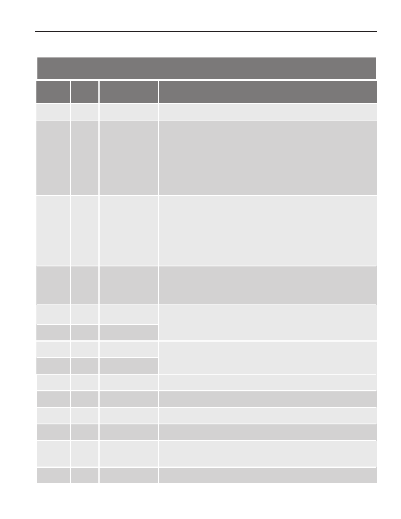
59
WATER HEATING UNIT CONTROLLER FAULT AND ALERT CONDITIONS
If the error code is displayed on the computer board of the water heater or remote controller and/or temperature controller,
please check the following. After checking, consult with the manufacturer.
Table 23. Control Board Green LED Flash Codes
Controller
Green
LED
Malfunction
Description
Diagnosis
031 One
Flash
Incorrect DIP switch
setting
• Check the DIP switch settings on the control board (Part #701).
101 Five
Flashes
Warning for the
“991” error code
• Check the gas type of the water heater.
• Check if there is any blockage in the intake air and/or exhaust.
• If the water heater is installed as a direct-vent system, check whether there is
enough distance between the intake air terminal and the exhaust terminal.
• Check the altitude/elevation of area of where the water heater is installed.
• Check if there is grease and/or dirt in the burner (Part #101) and the fan motor
(Part #103), especially if the water heater has been installed in a contaminated
area.
111 Three
Flashes
Ignition failure • Check if the Hi-limit switch (Part #412) is properly functioning.
• Check for connection/breakage of wires (Part #413, 708, 709, 711) burn marks
on the computer board (Part #701), and/or soot on the ame rod (Part #108).
• Check if there is a buzzing spark ignition sound coming from the burner (Part
#101) when water heater prepares for combustion.
• Listen for the double “clunk” sound coming from gas valve assembly (Part
#102) when water heater goes into combustion.
• Check if there is leaking from heat exchanger (Part #401).
121 Three
Flashes
Loss of ame • Check if the Hi-limit switch (Part #412) is functioning properly.
• Check for connection/breakage of wires (Part #413, 708, 709, 711) burn marks
on the computer board (Part #701), and/or soot on the ame rod (Part #108).
• Check if there is leaking from heat exchanger (Part #401).
311 Two
Flashes
Heat exchanger
thermistor failure
• Check for connection/breakage of wires and/or debris on thermistor (Part #407,
408, 411, 715).
321 Two
Flashes
Inlet thermistor
failure
331 Two
Flashes
Outlet thermistor
failure
• Check for connection/breakage of wires and/or debris on thermistor (Part #407,
408, 411, 715).
341 Two
Flashes
Exhaust thermistor
failure
391 Two
Flashes
Air-fuel ratio rod
failure
• Check for connection/breakage of wires (Part #709) and/or soot on the AFR rod
(Part #108).
441 Two
Flashes
Flow sensor failure • Check for connection/breakage of wires and/or debris on the ow sensor impel-
ler (Part #402).
510 Six
Flashes
Abnormal main gas
solenoid valve
• Check for connection/breakage of wires (Part #708) and/or burn marks on the
computer board (Part #701).
551 Six
Flashes
Abnormal gas sole-
noid valve
• Check for connection/breakage of wires (Part #708) and/or burn marks on the
computer board (Part #701).
611 Four
Flashes
Fan motor fault • Check for connection/breakage of wires, dust buildup in the fan motor (Part
#103) and/or burn marks on the computer board (Part #701).
• Check for frozen/corrosion of connectors (Part #103).
651 Four
Flashes
Flow adjustment
valve fault
• Inspect the ow adjustment valve (Part #402), for connection/breakage of
wires, locked motor drive due to scale buildup, and/or water leakage.

60
Table 23. Control Board Green LED Flash Codes
Controller
Green
LED
Malfunction
Description
Diagnosis
661 Four
Flashes
Bypass valve fault • Inspect the bypass valve (Part #403), for connection/breakage of wires, locked
motor drive due to scale buildup, and/or water leakage.
701
One
Flash
Computer board
fault
• Check for connection/breakage of wires (Part #714).
711 One
Flash
Gas solenoid valve
drive circuit failure
• Refer to the 111 and 121 error codes.
721 Six
Flashes
False ame detec-
tion
• Check if condensate drain is installed on the vent collar of the water heater.
• Check if there is leaking from heat exchanger (Part #401).
741 N/A Miscommunica-
tion between water
heater and remote
controller
• Check the model type of the remote controller.
• Inspect the connections between the water heater and remote controller.
• Check the power supply of the water heater.
751 N/A Miscommunica-
tion between water
heater and tempera-
ture controller
• Inspect the connections between the water heater and temperature controller.
• Check the power supply of the water heater.
941 Five
Flashes
Abnormal exhaust
temperature
• Check if the set temperature is higher than 140°F (60°C) and the system is
Recirculation.
991 Five
Flashes
Imperfect combus-
tion
• Check the gas type of the water heater.
• Inspect the environment around the water heater. Determine how long the unit
has been installed.
• Check the altitude/elevation of the area of where the water heater is installed.
• Check if there is any blockage in the intake air and/or exhaust.
• If the water heater is installed as a direct-vent system, check whether there is
enough distance between the intake air terminal and the exhaust terminal.
• Check if there is grease and/or dirt in the burner (Part #101) and the fan motor
(Part #103), especially if the water heater has been installed in a contaminated
area.
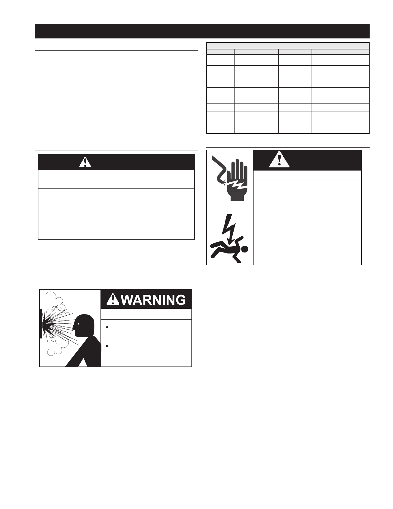
61
GENERAL
Keep water heater area clear and free from combustible
materials, gasoline, and other ammable vapors and liquids.
See Locating the Water Heater (page 11).
Water heater maintenance includes periodic tank ushing
and cleaning, and removal of lime scale. The water heater
should be inspected and adjusted to maintain proper
combustion. See Initial Operation (page 49). A periodic
inspection of the venting system should be made, see Table
24 (page 61). Where used, water circulating pump(s)
should be oiled according to the pump manufacturers
recommendations.
PRECAUTIONS
Do not operate the water heater if it has
been exposed to or exhibits the following:
Exposed to flooding or water damage
.
•
External damage.
•
Firing without water.
•
Sooting.
•
Do not operate the water heater until all corrective steps
have been made by a qualified service technician.
CAUTION
Never operate the water heater without rst being certain it is
lled with water and a properly sized and rated Temperature-
Pressure Relief Valve is installed in the relief valve opening
on the water heater. See Water Line Connections (page
44).
Explosion Hazard
Overheated water can cause
water tank explosion.
Properly sized temperature and
pressure relief valve must be
installed in the opening provided.
If overheating occurs or the gas supply fails to shut off, turn
off the Main Gas Shutoff valve. See Figure 44 (page 39).
Table 24. Maintenance Schedule
Component Operation Interval Required
Cold water
inlet lter
Inspection/
Cleaning
Annually
See Draining the Water
Heating Unit.
Burner Inspection/Cleaning Annually
• Check for dust, lint,
grease or dirt.
• Check the burner
ames (Figure 59)
Pressure
Only Relief
Valve
Test Operation Semi Annually Test
T&P Valve Test Operation Semi Annually Test
Vent System Inspection Annually
• Check for any leaks,
corrosion, blockages
or damage.
• Reseal/Repair
WATER HEATING UNIT MAINTENANCE AND SERVICE
WARNING
Shock or Electrocution Hazard
• Turn off the electrical power supply
and close the manual gas shutoff
valve and the manual water control
valve before servicing.
• Failure to do so could result in
severe personal injury, or death.
• Clean the cold-water inlet lter. (Refer to Draining the
Water Heating Unit (page 62).
• Be sure that all openings for combustion and ventilation
air are not blocked.
• The venting system should be checked annually for any
leaks, corrosion, blockages or damage.
• The burner should be checked annually for dust, lint,
grease or dirt.
• Keep the area around the water heater clear. Remove
any combustible materials, gasoline or any ammable
vapors and liquids.
• If the relief valve discharges periodically, it may be due
to thermal expansion in a closed water supply system.
Contact the water supplier or local plumbing inspector
on how to correct this situation.
• Visually check the burner ames (see below) through
the burner window in the burner assembly located at
the middle of the water heater.
MAINTENANCE
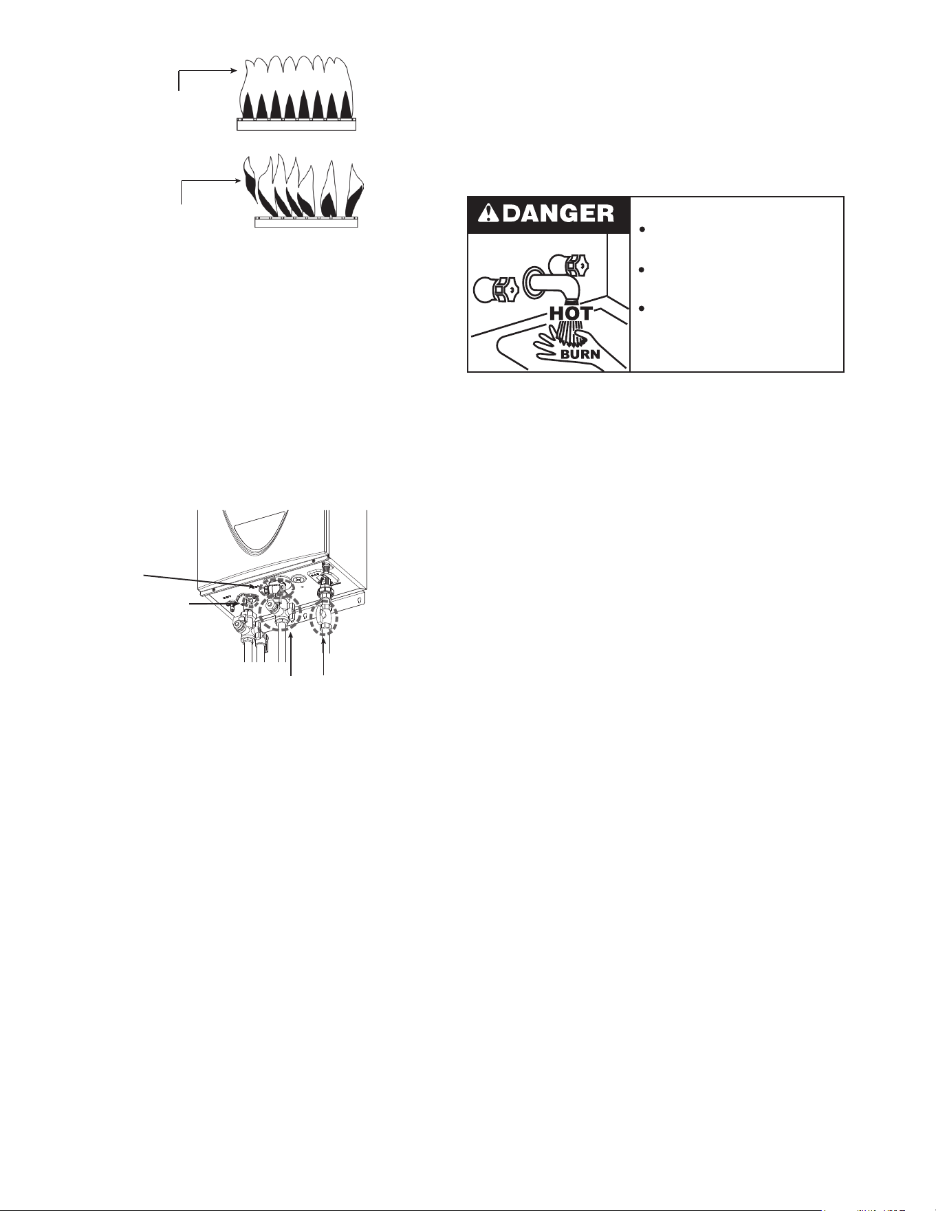
62
DRAINING AND FLUSHING THE STORAGE TANK
It is recommended that the water heater storage tank be
drained and ushed every 6 months to reduce sediment
buildup. The water heater should be drained if being shut
down during freezing temperatures. See Features and
Components (page 7) for the location of the water
heater components described below.
Burn hazard.
Hot water discharge.
Keep clear of Temperature-
Pressure Relief Valve
discharge outlet.
Draining the Water Heater Storage Tank
To drain the water heater storage tank, do the following:
1. Turn off the electrical supply to the water heater.
2. Turn off the gas supply at the Main Gas Shutoff Valve if
the water heater is going to be shut down for an extended
period.
3. Ensure the cold water inlet valve is open.
4. Open a nearby hot water faucet and let the water run
until the water is no longer hot.
5. Connect a hose to the water heater drain valve and
terminate it to an adequate drain.
6. Close the cold water inlet valve.
7. Open the water heater drain valve and allow all the water
to drain from the storage tank.
8. Close the water heater drain valve when all water in the
storage tank has drained.
9. Close the hot water faucet opened in Step 5.
10. If the water heater is going to be shut down for an
extended period, the drain valve should be left open.
Flushing the Water Heater Storage Tank
1. Turn off the electrical supply to the water heater.
2. Ensure the cold water inlet valve is open.
3. Open a nearby hot water faucet and let the water run
until the water is no longer hot. Then close the hot water
faucet.
4. Connect a hose to the drain valve and terminate it to an
adequate drain.
5. Ensure the drain hose is secured before and during the
entire ushing procedure. Flushing is performed with
system water pressure applied to the water heater.
6. Open the water heater drain valve to ush the storage
tank.
7. Flush the water heater storage tank to remove sediment
and allow the water to ow until it runs clean.
8. Close the water heater drain valve when ushing is
completed.
9. Remove the drain hose.
Blue Flame
Normal Condition
Flame blowing up
Abnormal Condition
(Air Rich)
Figure 59. Burner Flame Visual Check
The manufacturer recommends having the unit checked
once a year or as necessary by a licensed technician.
If repairs are needed, any repairs should be done by a
licensed technician.
DRAINING THE WATER HEATING UNIT
1. Close the manual gas shutoff valve.
2. Turn off power to the unit and wait a couple of seconds.
Turn on again.
3. Wait 30 seconds, and then turn off power to the unit.
4. Close the inlet water valve.
Small Drain Plug
Large Drain Plug
with Filter
Water Inlet Valve
Gas Inlet Valve
Figure 60. Drain Plugs
5. Open all hot water taps in the house. When the residual
water ow has ceased, close all hot water taps.
6. Have a bucket or pan to catch the water from the unit’s
drain plugs. If Isolation valves are installed, open the
drains to drain the water. If isolation valves are not
installed, unscrew the two drain plugs (large and small) to
drain all the water out of the unit. Do not lose the o-rings
that will be on the two drain plugs.
7. Wait a few minutes to ensure all water has completely
drained from the unit.
8. Clean the lter: Check the water lter located within the
cold inlet. With a tiny brush, clean the water lter of any
debris which may have accumulated and reinsert the
lter back into the cold water inlet.
9. Securely screw the drain plugs back into place.
10. Hand- tighten only.
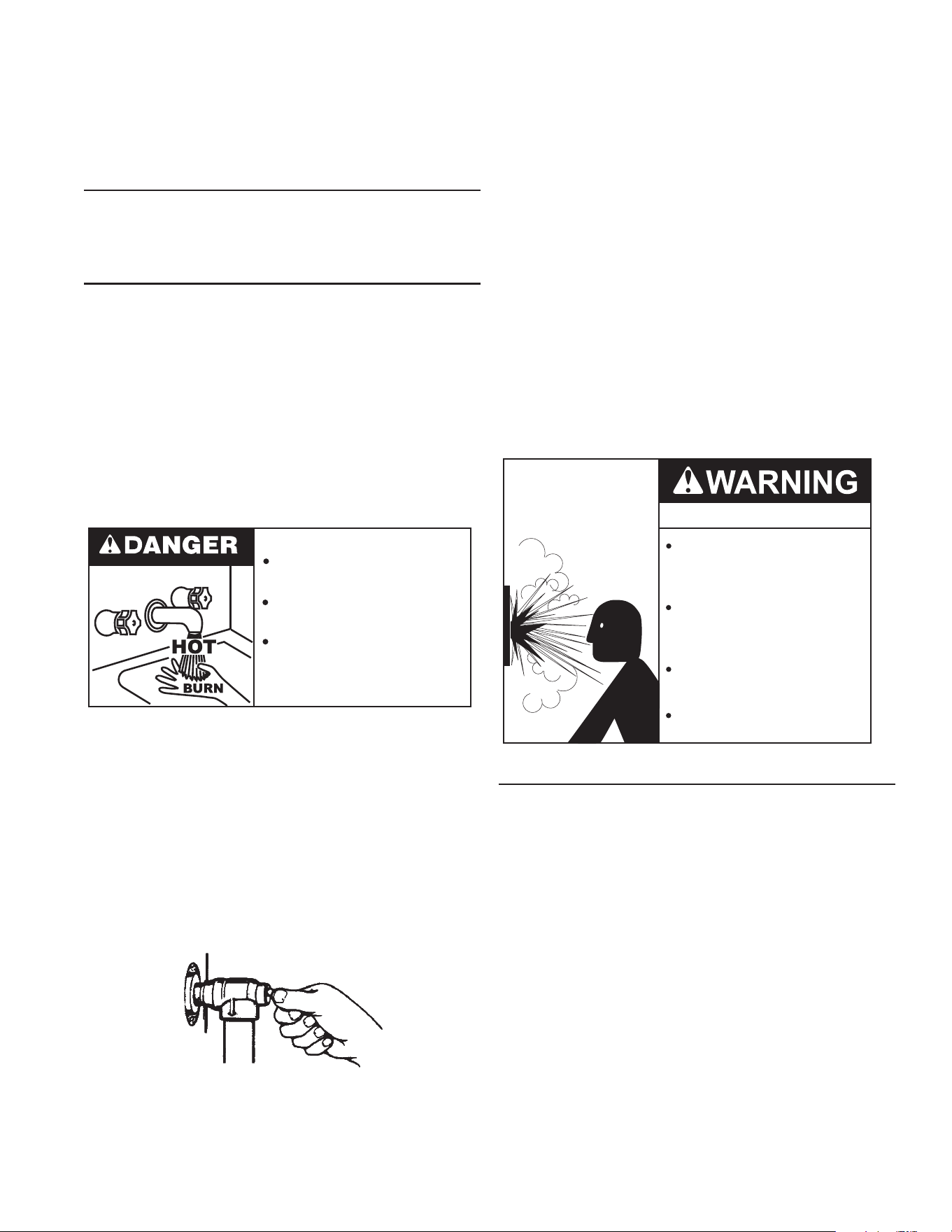
63
If the Temperature-Pressure Relief Valve on the water
heater weeps or discharges periodically, this may be due
to thermal expansion.
NOTE: Excessive water pressure is the most common
cause of Temperature-Pressure Relief Valve leakage.
Excessive water system pressure is most often caused by
"thermal expansion" in a "closed system." See Thermal
Expansion (page 15) and Closed Water Systems
(page 15). The Temperature-Pressure Relief Valve is
not intended for the constant relief of thermal expansion.
Temperature-Pressure Relief Valve leakage due to pressure
build up in a closed system that does not have a thermal
expansion tank installed is not covered under the limited
warranty. See the Commercial Water Heater Limited
Warranty provided with this water heater.
Thermal expansion tanks must be installed on all closed
water systems.
DO NOT PLUG THE TEMPERATURE-PRESSURE
RELIEF VALVE OPENING. THIS CAN CAUSE PROPERTY
DAMAGE, SERIOUS INJURY OR DEATH.
Explosion Hazard
Temperature-Pressure Relief Valve
must comply with ANSI Z21.22-
CSA 4.4 and ASME code.
Properly sized temperature-
pressure relief valve must be
installed in opening provided.
Can result in overheating and
excessive tank pressure.
Can cause serious injury or death.
VENT SYSTEM MAINTENANCE
Examine the vent system every 6 months. Points of
inspection are as follows:
1. Check for obstructions and/or deterioration of the
intake air and/or vent piping and the intake air and vent
terminations. Replace immediately where needed.
2. The debris screens in the intake air and vent terminations
should be cleaned of foreign material and soot.
NOTE: Do not reach inside the vent termination
when the heater is in operation.
3. Check all vent system connections for leakage and repair
or reseal as necessary.
10. Fill the water heater - see Filling The Water Heater
Storage Tank (page 49).
11. Turn on the electrical supply to place the water heater
back in operation.
12. Allow the water heater to complete several heating cycles
to ensure it is operating properly.
DRAIN VALVE
The water heaters covered in this manual are equipped
with a drain valve, see Features and Components (page
7) for location.
RELIEF VALVE TESTS
Water heaters covered by this manual have two pressure
relief valves that should be tested periodically: the
Temperature-Pressure relief valve and the Pressure-Only
relief valve.
Test each of these valves every six months to ensure that
they are in operating condition.
When checking the valves' operation, make sure that (1) no
one is in front of or around the outlet of the discharge line
of the valve being tested, and (2) that the water discharge
will not cause any property damage, as the water may be
extremely hot. Use care when operating valve as the valve
may be hot.
Burn hazard.
Hot water discharge.
Keep clear of Temperature-
Pressure Relief Valve
discharge outlet.
To check the relief valves, lift the lever at the end of the
valve several times, see Figure 61. The valve should seat
properly and operate freely.
If after manually operating the valve, it fails to completely
reset and continues to release water, immediately close
the cold water inlet to the water heater and drain the water
heater, see Water heating unit Maintenance and Service
(page 61). Replace the Temperature-Pressure Relief
Valve with a properly rated/sized new one, see Water Line
Connections (page 44) Water Piping Diagrams (page
66) for instructions on replacement.
DISCHARGE PIPE
TEMPERATURE-PRESSURE
RELIEF VALVE
Figure 61. Operating the Relief Valve Lever
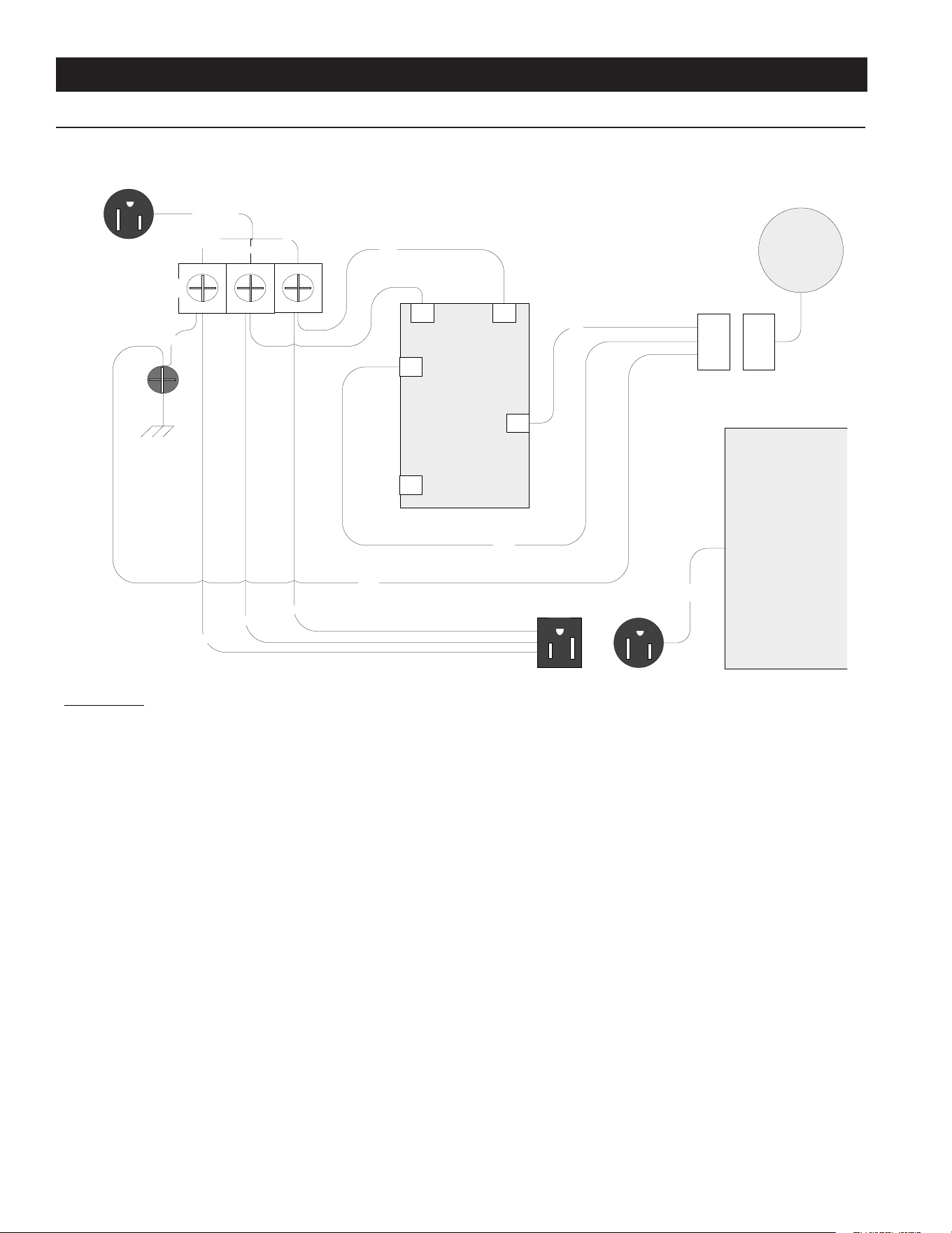
64
DIAGRAMS
WIRING DIAGRAM
= 18AWG AWM wire 105°C 600V UL 1015
Ground
Screw
Green
PUMP CONTROL
L1 L3
T4
T2
L4
INSTANT
HEATER
Green
PUMP
Power
Cord
PUMP
PLUG
Red
Yellow
Black
White
White
Black
Green
PUMP
PLUG
PlugReceptacle
Input Power Cord
Protective
Earth
L1
Neutral
Plug
Terminal
Block
Figure 62. Wiring Diagram
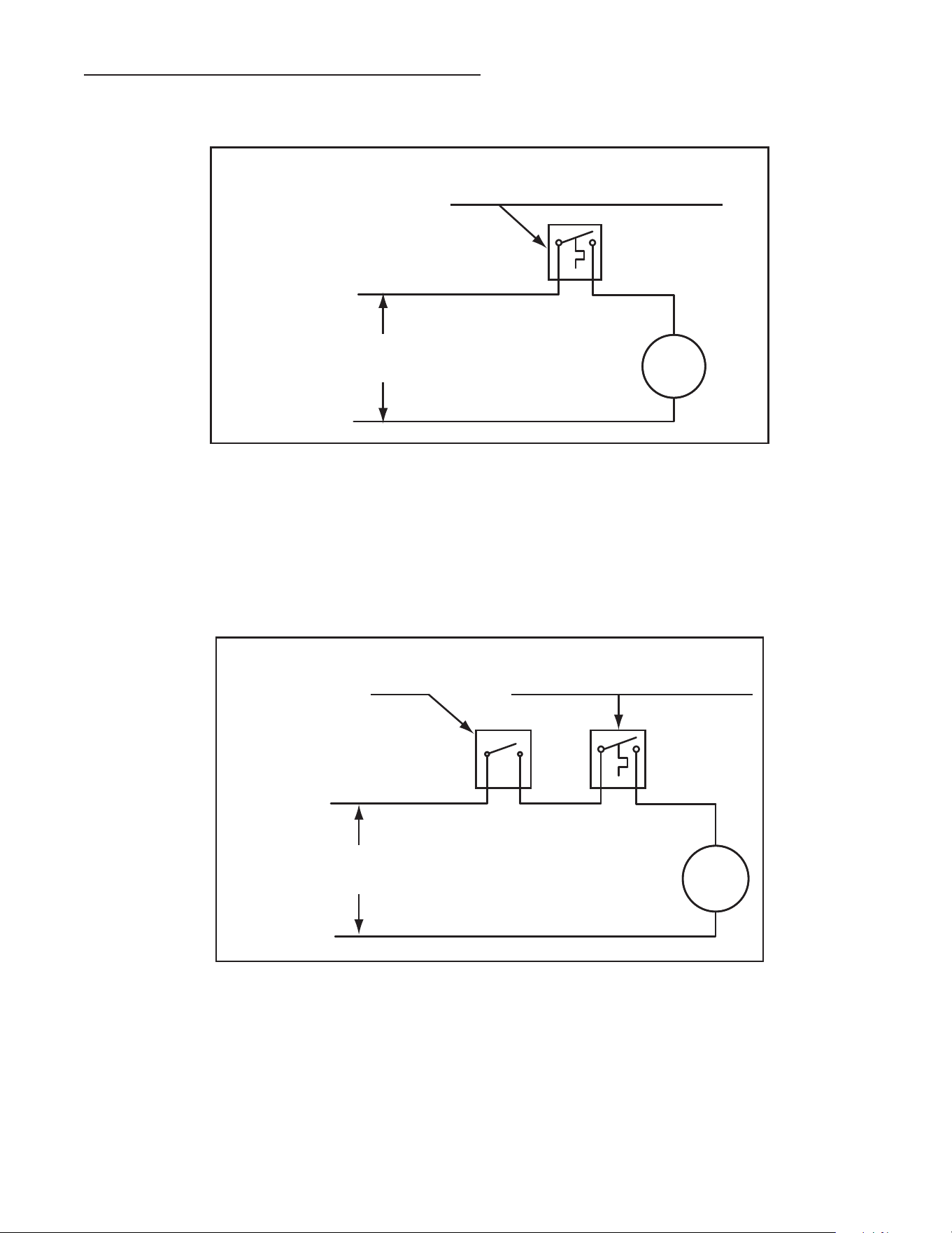
65
CIRCULATION PUMP WIRING DIAGRAMS
Figure 63. Circulating Pump Wiring Diagram - Storage Tank or Building Recirculation
Figure 64. Circulating Pump Wiring Diagram - Dishwasher Loop Toggle Switch
FIELD SUPPLIED TEMPERATURE CONTROL
INSTALLED IN THE STORAGE TANK
OR CIRCULATING LOOP RETURN LINE
CIRC
PUMP
MOTOR
L1 HOT
L2 NEUTRAL
120 VAC
POWER
NOTE: USE SEPARATE 120 VAC POWER
SUPPLY FOR PUMP CIRCUIT. DO NOT
SHARE POWER WITH WATER HEATER AS
THIS MAY CAUSE ELECTRICAL LINE
NOISE AND LEAD TO ERRATIC CONTROL
SYSTEM OPERATION.
FIELD SUPPLIED TEMPERATURE
CONTROL INSTALLED IN THE
CIRCULATING LOOP RETURN LINE
DISHWASHER
TOGGLE
SWITCH
CIRC
PUMP
MOTOR
L1 HOT
L2 NEUTRAL
120 VAC
POWER
NOTE: USE SEPARATE 120 VAC POWER
SUPPLY FOR PUMP CIRCUIT. DO NOT
SHARE POWER WITH WATER HEATER AS
THIS MAY CAUSE ELECTRICAL LINE
NOISE AND LEAD TO ERRATIC CONTROL
SYSTEM OPERATION.
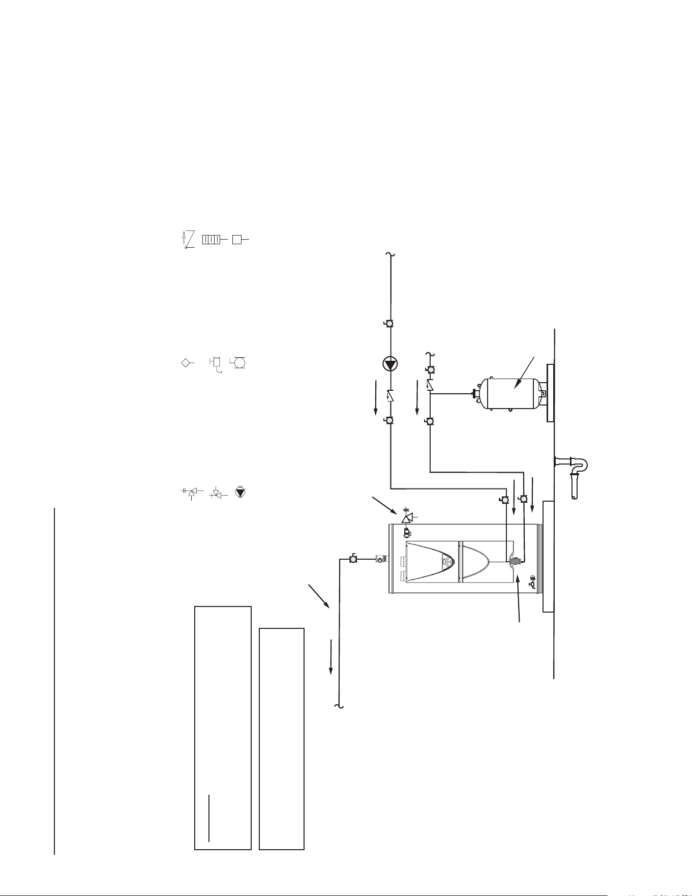
66
5. If a pump is being installed between a water heater and storage tank or on a building recirculation
loop wire according to Figure 63 (page 65).
6. If a pump is being installed in a recirculation loop between the water heater and a commercial
dishwasher wire according to Figure 63 or Figure 64 (page 65).
WATER PIPING DIAGRAMS
Before installation of water piping review the following:
1. See Mixing Valves (page 14).
2. See Dish-washing Machines (page 15).
3. See Thermal Expansion and Closed Water Systems (page 15).
4. See Water Line Connections (page 44).
ONE WA
TER HEA
TER, SINGLE TEMPERA
TURE
WITH B
UILDING RECIR
CULATION
ONE WA
TER HEA
TER, SINGLE TEMPERA
TURE
WITH B
UILDING RECIR
CULATION
N
OTES
:
1. Preferred piping method.
2. The temperature and pressure relief valve setting shall not exceed pressure rating of any component in the system.
3. Service valves are shown for servicing unit. However, local codes shall govern their usage.
LEGEND
TEMPERATURE &
PRESSURE RELIEF VALVE
PRESSURE RELIEF VALVE
CIRCULATING PUMP
TEMPERATURE CONTROL
PROBE
DRAIN
FULL PORT BALL VALVE
TEMPERATURE GAGE
WATER FLOW SWITCH
CHECK VALVE
W
ARNING
: THIS DRAWING SHOWS SUGGESTED
PIPING
CONFIGURATION AND OTHER DEVICES;
CHEC
K WITH LOCAL CODES AND ORDINANCES
FOR ADDITIONAL REQUIREMENTS.
ANY MATERIAL, COMPONENT OR VENDOR CHANGE
MUST
HAVE PRIOR APPROVAL BY THE APPLICABLE
PRODUCT ENGINEERING DEPARTMENT.
FINISHED FLOOR
HOT WATER
RETURN
COLD WATER
SUPPLY
EXPANSION
TANK
Pipe T&P to
Open Drain
Hot Water to
Fixtures
Tee Fitting
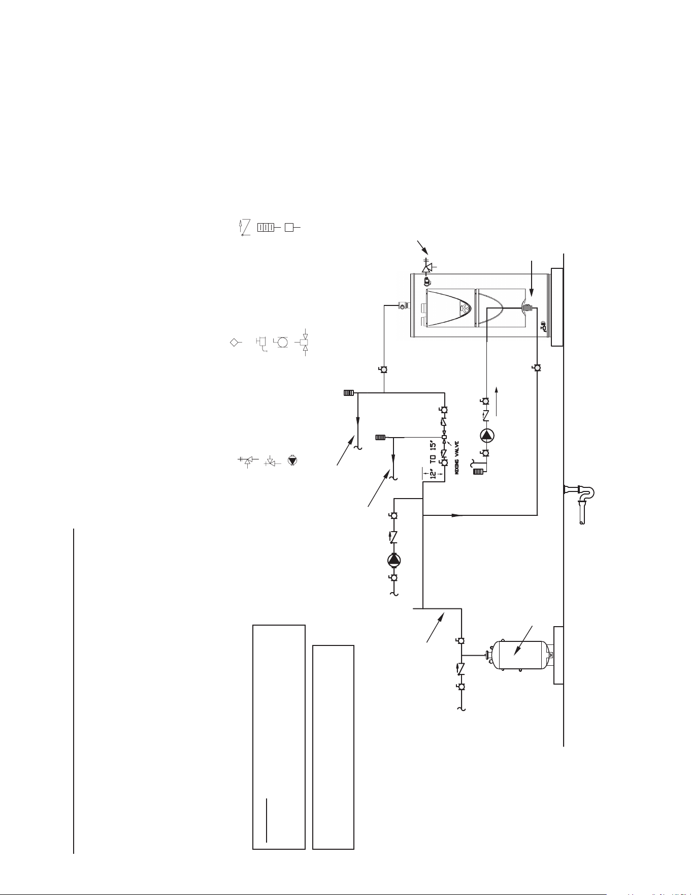
67
5. If a pump is being installed between a water heater and storage tank or on a building recirculation loop
wire according to Figure 63 (page 65).
6. If a pump is being installed in a recirculation loop between the water heater and a commercial dishwasher
wire according to Figure 63 or Figure 64 (page 65).
WATER PIPING DIAGRAMS
Before installation of water piping review the following:
1. See Mixing Valves (page 14)
2. See Dish-washing Machines (page 15).
3. See Thermal Expansion and Closed Water Systems (page 15).
4. See Water Line Connections (page 44).
ONE WATER HEATER, TWO TEMPERATURE
WITH HIGH TEMPERAURE LOOP RECIRCULATION
WITH BUILDING RECIRCULATION
NOTES
:
1
. Preferred piping method.
2
. The temperature and pressure relief valve setting shall not exceed pressure rating of any component in the system.
3. Service valves are shown for servicing unit. However, local codes shall govern their usage.
LEGEND
TEMPERATURE &
PRESSURE RELIEF VALVE
PRESSURE RELIEF VALVE
CIRCULATING PUMP
TEMPERATURE CONTROL
PROBE
DRAIN
FULL PORT BALL VALVE
MIXING VALVE
TEMPERATURE GAGE
WATER FLOW SWITCH
CHECK VALVE
W
ARNING
: THIS DRAWING SHOWS SUGGESTED
PIPING
CONFIGURATION AND OTHER DEVICES;
CHEC
K WITH LOCAL CODES AND ORDINANCES
FOR
ADDITIONAL REQUIREMENTS.
ANY MATERIAL, COMPONENT OR VENDOR CHANGE
MUST HAVE PRIOR APPROVAL BY THE APPLICABLE
PRODUCT ENGINEERING DEPARTMENT.
FINISHED FLOOR
HOT WATER
OUTLET
HOT
TEMPERED WATER
RETURN
TEMPERED
WATER
OUTLET
COLD WATER
SUPPLY
COLD
EXPANSION
TANK
Pipe T&P to
Open Drain
Hot Water
Return
Tee Fitting
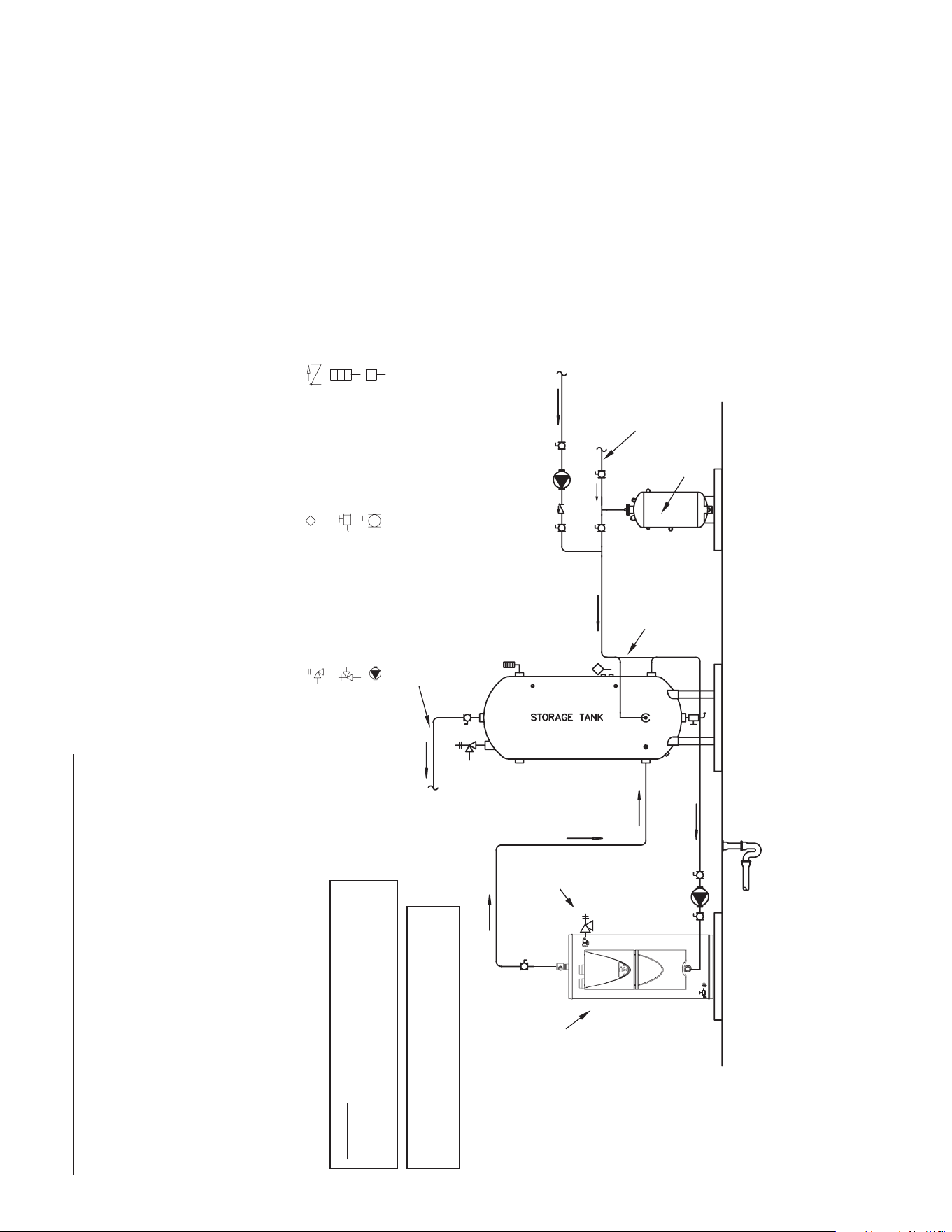
68
5. If a pump is being installed between a water heater and storage tank or on a building recirculation loop wire
according to Figure 63 (page 65).
6. If a pump is being installed in a recirculation loop between the water heater and a commercial dishwasher
wire according to Figure 63 or Figure 64 (page 65).
WATER PIPING DIAGRAMS
Before installation of water piping review the following:
1. See Mixing Valves (page 14).
2. See Dish-washing Machines (page 15).
3. See Water Line Connections (page 44).
4. See Thermal Expansion and Closed Water Systems (page
15).
ONE WATER HEATER, SINGLE TEMPERATURE
WITH VERTICAL ST
ORAGE TANK FORCED RECIRCULATION
WITH B
UILDING RECIR
CULATION
N
OTES
:
1. Preferred piping method.
2. The temperature and pressure relief valve setting shall not exceed pressure rating of any component in the system.
3. Service valves are shown for servicing unit. However, local codes shall govern their usage.
4. The tank temperature control should be wired to and control the pump between the water heater(s) and the storage tank(s).
5. The water heater’s operating thermostat should be set 5 degrees F higher than the tank temperature control.
LEGEND
TEMPERATURE &
PRESSURE RELIEF VALVE
PRESSURE RELIEF VALVE
CIRCULATING PUMP
TEMPERATURE CONTROL
PROBE
DRAIN
FULL PORT BALL VALVE
TEMPERATURE GAGE
WATER FLOW SWITCH
CHECK VALVE
W
ARNING
: THIS DRAWING SHOWS SUGGESTED
PIPING
CONFIGURATION AND OTHER DEVICES;
CHECK
WITH LOCAL CODES AND ORDINANCES
FOR
ADDITIONAL
REQUIREMENTS.
ANY MATERIAL, COMPONENT OR VENDOR CHANGE
MUST
HAVE PRIOR APPROVAL BY THE APPLICABLE
PRODUCT
ENGINEERING DEPARTMENT.
FINISHED
FLOOR
HOT WATER
RETURN
PIPE T&P TO
OPEN DRAIN
COLD WATER
SUPPLY
HOT WATER
TO FIXTURES
ALT. COLD WATER
CONNECTION
EXPANSION
TANK
Pipe T&P to
Open Drain
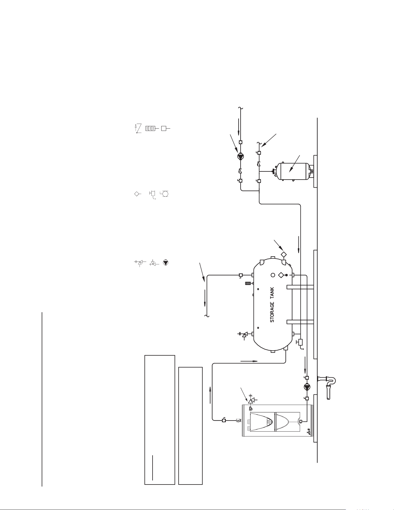
69
WATER PIPING DIAGRAMS
Before installation of water piping review the following:
1. See Mixing Valves (page 14).
2. See Dish-washing Machines (page 15).
3. See Water Line Connections (page 44).
4. See Thermal Expansion and Closed Water Systems (page
15).
ONE WATER HEATER, SINGLE TEMPERATURE
WITH HORIZONTAL STORAGE TANK FORCED RECIRCULATION
WITH BUILDING RECIRCULATION
N
OTES
:
1. Preferred piping method.
2. The temperature and pressure relief valve setting shall not exceed pressure rating of any component in the system.
3. Service valves are shown for servicing unit. However, local codes shall govern their usage.
4. The tank temperature control should be wired to and control the pump between the water heater(s) and the storage tank(s).
5. The water heater’s operating thermostat should be set 5 degrees F higher than the tank temperature control.
LEGEND
TEMPERATURE &
PRESSURE RELIEF VALVE
PRESSURE RELIEF VALVE
CIRCULATING PUMP
TEMPERATURE CONTROL
PROBE
DRAIN
FULL PORT BALL VALVE
TEMPERATURE GAGE
WATER FLOW SWITCH
CHECK VALVE
W
ARNING
: THIS DRAWING SHOWS SUGGESTED
PIPING
CONFIGURATION AND OTHER DEVICES;
CHECK
WITH LOCAL CODES AND ORDINANCES
FOR
ADDITIONAL
REQUIREMENTS.
ANY MATERIAL, COMPONENT OR VENDOR CHANGE
MUST
HAVE PRIOR APPROVAL BY THE APPLICABLE
PRODUCT
ENGINEERING DEPARTMENT.
FINISHED
FLOOR
HOT WATER
RETURN
PIPE T&P TO
OPEN DRAIN
HOT WATER
TO FIXTURES
CIRCULATING
PUMP
ALTERNATE
LOCATION
COLD WATER
SUPPLY
EXPANSION
TANK
5. If a pump is being installed between a water heater and storage tank or on a building recirculation loop wire
according to Figure 63 (page 65).
6. If a pump is being installed in a recirculation loop between the water heater and a commercial dishwasher wire
according to Figure 63 or Figure 64 (page 65).
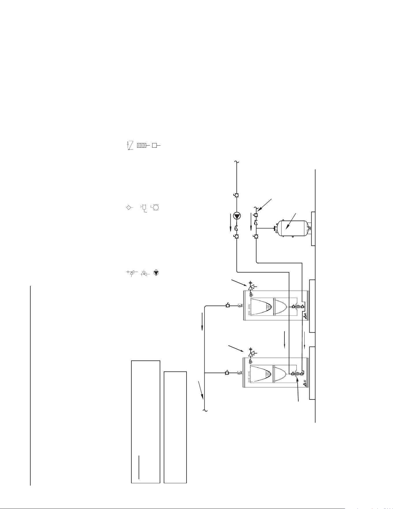
70
WATER PIPING DIAGRAMS
Before installation of water piping review the following:
1. See Mixing Valves (page 14).
2. See Dish-washing Machines (page 15).
3. See Water Line Connections (page 44).
4. See Thermal Expansion and Closed Water Systems (page 15).
TWO WATER HEATERS, SINGLE TEMPERATURE
WITH BUILDING RECIRCULATION
N
OTES
:
1. Preferred piping method.
2. The temperature and pressure relief valve setting shall not exceed pressure rating of any component in the system.
3. Service valves are shown for servicing unit. However, local codes shall govern their usage.
LEGEND
TEMPERATURE &
PRESSURE RELIEF VALVE
PRESSURE RELIEF VALVE
CIRCULATING PUMP
TEMPERATURE CONTROL
PROBE
DRAIN
FULL PORT BALL VALVE
TEMPERATURE GAGE
WATER FLOW SWITCH
CHECK VALVE
W
ARNING
: THIS DRAWING SHOWS SUGGESTED
PIPING
CONFIGURATION AND OTHER DEVICES;
CHEC
K WITH LOCAL CODES AND ORDINANCES
FOR ADDITIONAL REQUIREMENTS.
ANY MATERIAL, COMPONENT OR VENDOR CHANGE
MUST
HAVE PRIOR APPROVAL BY THE APPLICABLE
PRODUCT ENGINEERING DEPARTMENT.
FINISHED
FLOOR
HOT WATER
RETURN
HOT WATER
TO FIXTURES
COLD WATER
SUPPLY
EXPANSION
TANK
PIPE T&P TO
OPEN DRAIN
PIPE T&P TO
OPEN DRAIN
Tee Fitting
5. If a pump is being installed between a water heater and storage tank or on a building
recirculation loop wire according to Figure 63 (page 65).
6. If a pump is being installed in a recirculation loop between the water heater and a
commercial dishwasher wire according to Figure 63 or Figure 64 (page 65).
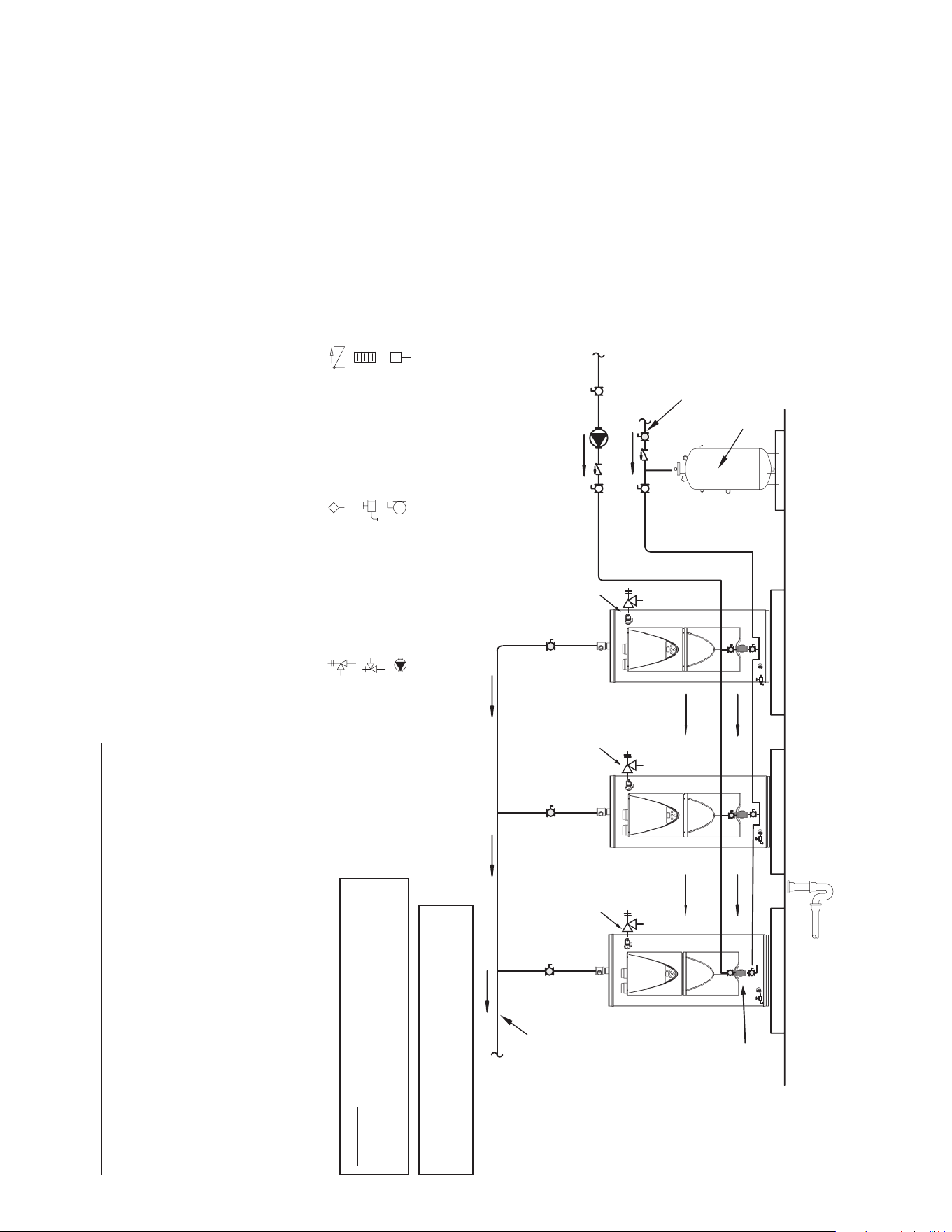
71
WATER PIPING DIAGRAMS
Before installation of water piping review the following:
1. See Mixing Valves (page 14).
2. See Dish-washing Machines (page 15).
3. See Water Line Connections (page 44).
4. See Thermal Expansion and Closed Water Systems (page 15).
THREE WATER HEATERS, SINGLE TEMPERATURE
WITH BUILDING RECIRCULATION
NOTES
:
1
. Preferred piping method.
2
. The temperature and pressure relief valve setting shall not exceed pressure rating of any component in the system.
3. Service valves are shown for servicing unit. However, local codes shall govern their usage.
LEGEND
TEMPERATURE &
PRESSURE RELIEF VALVE
PRESSURE RELIEF VALVE
CIRCULATING PUMP
TEMPERATURE CONTROL
PROBE
DRAIN
FULL PORT BALL VALVE
TEMPERATURE GAGE
WATER FLOW SWITCH
CHECK VALVE
W
ARNING
: THIS DRAWING SHOWS SUGGESTED
PIPING
CONFIGURATION AND OTHER DEVICES;
CHEC
K WITH LOCAL CODES AND ORDINANCES
FOR
ADDITIONAL REQUIREMENTS.
ANY MATERIAL, COMPONENT OR VENDOR CHANGE
MUST
HAVE PRIOR APPROVAL BY THE APPLICABLE
PRODUCT ENGINEERING DEPARTMENT.
FINISHED
FLOOR
HOT WATER
RETURN
PIPE T&P TO
OPEN DRAIN
HOT WATER
TO FIXTURES
COLD WATER
SUPPLY
EXPANSION
TANK
PIPE T&P TO
OPEN DRAIN
PIPE T&P TO
OPEN DRAIN
Tee Fitting
5. If a pump is being installed between a water heater and storage tank or on a building recirculation loop wire
according to Figure 63 (page 65).
6. If a pump is being installed in a recirculation loop between the water heater and a commercial dishwasher
wire according to Figure 63 or Figure 64 (page 65).
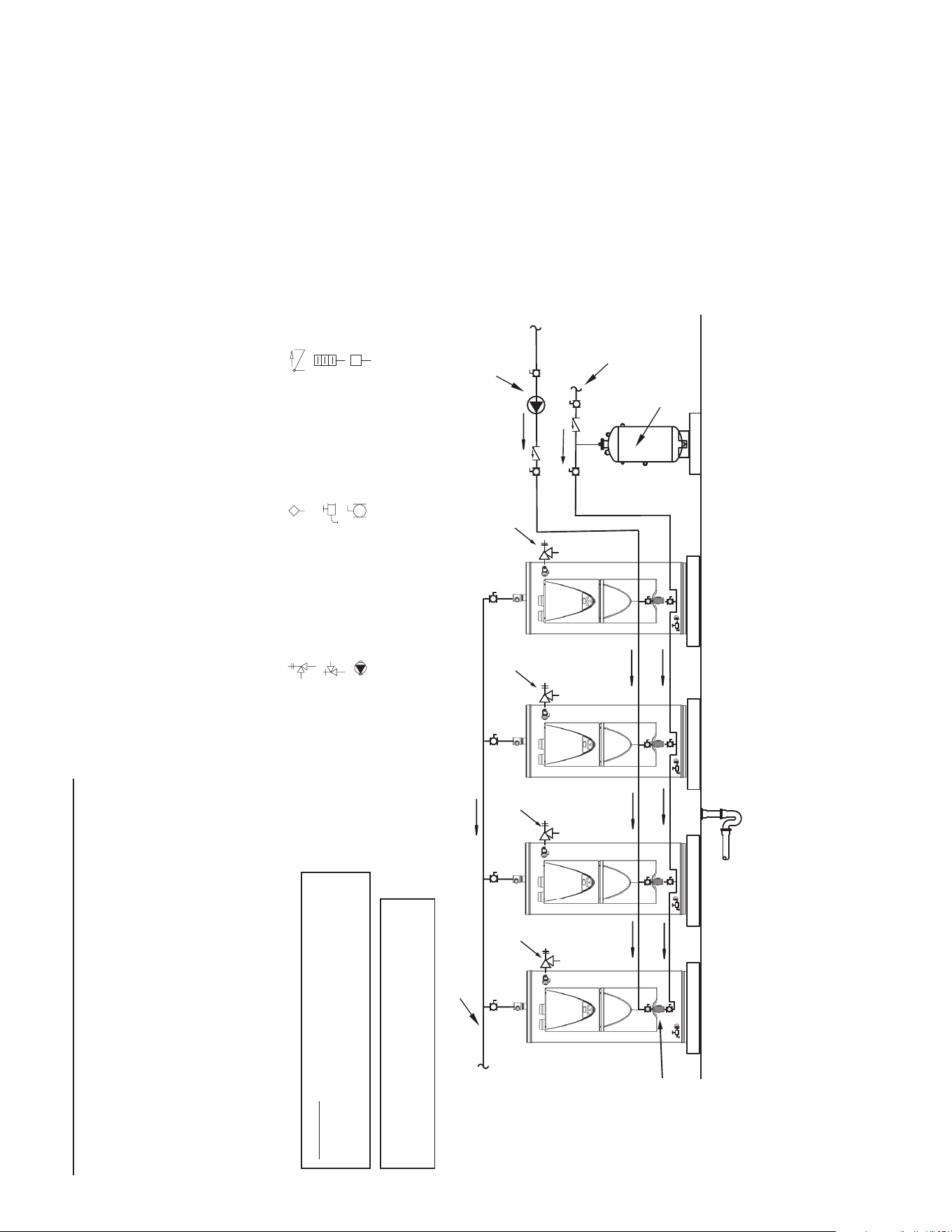
72
5. See Water Line Connections (page 44).
6. If a pump is being installed between a water heater and storage tank or on a building recirculation loop wire
according to Figure 63 (page 65).
7. If a pump is being installed in a recirculation loop between the water heater and a commercial dishwasher wire
according to Figure 63 or Figure 64 (page 65).
WATER PIPING DIAGRAMS
Before installation of water piping review the following:
1. See Mixing Valves (page 14).
2. See Dish-washing Machines (page 15).
3. See Water Line Connections (page 44).
4. See Thermal Expansion and Closed Water Systems (page
15).
PIPE T&P TO
OPEN DRAIN
PIPE T&P TO
OPEN DRAIN
FOUR WATER HEATERS, SINGLE TEMPERATURE
WITH BUILDING RECIRCULATION
N
OTES
:
1. Preferred piping method.
2. The temperature and pressure relief valve setting shall not exceed pressure rating of any component in the system.
3. Service valves are shown for servicing unit. However, local codes shall govern their usage.
W
ARNING
: THIS DRAWING SHOWS SUGGESTED
PIPING
CONFIGURATION AND OTHER DEVICES;
CHEC
K WITH LOCAL CODES AND ORDINANCES
FOR ADDITIONAL REQUIREMENTS.
ANY MATERIAL, COMPONENT OR VENDOR CHANGE
MUST
HAVE PRIOR APPROVAL BY THE APPLICABLE
PRODUCT ENGINEERING DEPARTMENT.
FINISHED
FLOOR
HOT WATER
RETURN
COLD WATE R
SUPPLY
TANK TEMPERATURE
CONTROL
EXPANSION
TANK
LEGEND
TEMPERATURE &
PRESSURE RELIEF VALVE
PRESSURE RELIEF VALVE
CIRCULATING PUMP
TEMPERATURE CONTROL
PROBE
DRAIN
FULL PORT BALL VALVE
TEMPERATURE GAGE
WATER FLOW SWITCH
CHECK VALVE
PIPE T&P TO
OPEN DRAIN
PIPE T&P TO
OPEN DRAIN
Tee Fitting
Hot Water to
Fixtures

73
NOTES

For additional information contact:
1-800-527-1953
www.hotwater.com
