
AC-MX-44X
User Manual
48 Gbps 4x4 HDMI Matrix Switcher

Page 2 of 35
AC-MX-44X User Manual
Contents
Important Safety Instructions ..................................................................................................................................................... 4
Safety Classifications in this Document ................................................................................................................................. 4
Electrical Shock Prevention ..................................................................................................................................................... 4
Weight Injury Prevention ......................................................................................................................................................... 4
Safety Statements .................................................................................................................................................................... 5
Introduction .................................................................................................................................................................................. 6
Features ..................................................................................................................................................................................... 6
Product Overview ......................................................................................................................................................................... 7
Box Contents ............................................................................................................................................................................ 7
Technical Specifications ........................................................................................................................................................... 7
Front and Rear Panel Overview .............................................................................................................................................. 9
Installation .................................................................................................................................................................................. 10
Rack Mounting ....................................................................................................................................................................... 10
Mounting Feet Assembly ....................................................................................................................................................... 10
Wiring and Connections ........................................................................................................................................................... 11
HDMI Cables .......................................................................................................................................................................... 11
USB Ports ............................................................................................................................................................................... 11
IR Wiring ................................................................................................................................................................................. 11
Ethernet/LAN ......................................................................................................................................................................... 11
RS-232 Control ....................................................................................................................................................................... 12
Analog Audio Output Ports .................................................................................................................................................. 13
S/PDIF Audio Output Ports ................................................................................................................................................... 13
AC Power Connection ........................................................................................................................................................... 13
Initial Setup ................................................................................................................................................................................ 13
Connecting Devices ............................................................................................................................................................... 13
Initial Setup ................................................................................................................................................................................ 14
Navigating the Web UI .............................................................................................................................................................. 15
Matrix ...................................................................................................................................................................................... 16
Video Matrix Switching ..................................................................................................................................................... 16
Extracted Audio Matrix Switching ................................................................................................................................... 17
I/O Config ............................................................................................................................................................................... 18
Input Settings ..................................................................................................................................................................... 19
Video Output Settings ...................................................................................................................................................... 19
Extracted Audio Output Settings ..................................................................................................................................... 20
Audio Configuration .......................................................................................................................................................... 21

Page 3 of 35
AC-MX-44X User Manual
System .................................................................................................................................................................................... 22
IP Settings .......................................................................................................................................................................... 22
RS-232 Settings .................................................................................................................................................................. 23
IP Control ........................................................................................................................................................................... 23
Admin Web Interface ........................................................................................................................................................ 23
User Web Interface ........................................................................................................................................................... 24
Hardware ........................................................................................................................................................................... 25
Cloud Services and Firmware Updates .......................................................................................................................... 25
Diagnostics ............................................................................................................................................................................. 28
HDMI Inputs ....................................................................................................................................................................... 28
HDMI Outputs ................................................................................................................................................................... 29
Console ................................................................................................................................................................................... 30
Command-List ................................................................................................................................................................... 31
Troubleshooting ........................................................................................................................................................................ 33
Maintenance .............................................................................................................................................................................. 33
Damage Requiring Service ....................................................................................................................................................... 33
Support ....................................................................................................................................................................................... 33
Warranty ..................................................................................................................................................................................... 34
The Basics ............................................................................................................................................................................... 34
Coverage Details ................................................................................................................................................................... 34
Red Tape ................................................................................................................................................................................. 34
Obtaining an RMA ................................................................................................................................................................. 35
Shipping .................................................................................................................................................................................. 35
Limitation on Liability ........................................................................................................................................................... 35
Exclusive Remedy .................................................................................................................................................................. 35

Page 4 of 35
AC-MX-44X User Manual
Important Safety Instructions
Before installing, configuring, and operating this device and other vendor equipment, AVPro Edge strongly
recommends that each dealer, integrator, installer, and all other necessary personnel access and read all the
required technical documentation, which can be located by visiting AVProEdge.com.
Read and understand all safety instructions, cautions, and warnings in this document and the labels on the
equipment.
Safety Classifications in this Document
Note:
Provides special information for installing, configuring, and operating this device with
other equipment.
Tip:
Provides suggestions and considerations for installing, configuring, and operating this
device with other equipment.
Important:
Provides special information that is critical for installing, configuring, and operating
this device with equipment.
Cau1on:
Provides special information to avoid situations that may cause damage to this device
and other equipment.
Warning:
Provides special information for avoiding situations that may cause physical danger to
the installer, end user, etc.
Electrical Shock Prevention
Electric Shock:
Provides special information that is critical for installing, configuring, and operating
this device and other equipment.
Electrical Disconnect:
Provides special information to avoid situations that may cause damage to this device
and other equipment.
Weight Injury Prevention
Weight Injury:
Two installers are required to handle some of the devices and equipment safely.
Failure to use two installers may result in injury.

Page 5 of 35
AC-MX-44X User Manual
Safety Statements
Follow all of the safety instructions listed below and apply them accordingly. Additional safety information will
be included where applicable.
1 Read and keep these instructions.
2 Heed and follow all warnings.
3 Clean devices and equipment only with a dry cloth.
4 Do not use the devices near water or expose them to rain and moisture.
5 Do not block any ventilation openings.
6 The devices and accessories should never be exposed to flames or excessive heat.
7 Only use attachments and accessories specified by the manufacturer.
8 Install in accordance with the manufacturer’s instructions.
9 Do not install near any heat sources, such as radiators, heat registers, stoves, or other heat apparatus.
10 Do not defeat the safety purpose of the polarized / grounding-type plug. A polarized plug has two
blades, one wider than the other. A grounding-type plug has two blades and a third grounding prong.
The wide blade, or third prong, is provided for your safety.
11 Protect the power cord from being walked on or pinched, particularly at plugs, convenience receptacles,
and where they exit from the devices.
12 Unplug the devices during lightning storms or when unused for long periods.
13 Never handle or touch the devices and power cord with damp hands to reduce the risk of electrical
shock or damage to them and their operators.
14 To reduce the risk of injury, some devices and equipment may require two installers to ensure safe
handling during installation. Failure to use two installers may result in injury.
15 Refer all servicing to qualified service personnel. Servicing is required when the devices have been
damaged in any way, such as the power cord or plug, liquid spilled, objects fallen into the devices,
exposed to rain or moisture, do not operate normally, or have been dropped.
Page 6 of 35
AC-MX-44X User Manual
Introduction
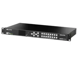
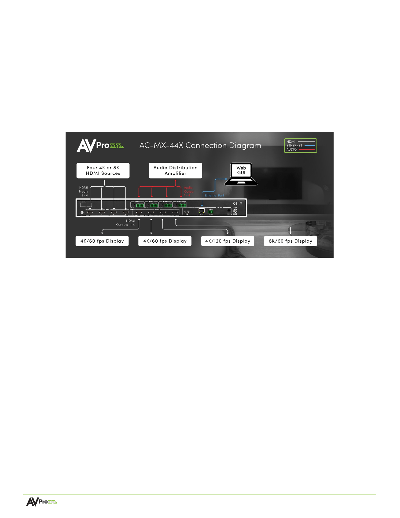
Thank you for choosing the AC-MX-44X, a 48 Gbps 8K capable HDMI matrix switcher designed for HDMI signals up
to 48 Gbps 8K HDMI with HDR, Variable Refresh Rate (VRR), and High Frame Rate (HFR) technology. Equipped with
four HDMI inputs and four HDMI outputs, the AC-MX-44X supports resolutions up to 8K with HDR, Dolby Vision, and
VRR. It features advanced EDID management, an 8K-to-4K scaler, and audio de-embedding for surround sound and
multi-zone audio setups. Built-in troubleshooting tools, such as test pattern generation, make installation and
maintenance easy. Ideal for a range of applications, the AC-MX-44X excels in high-end home theaters, enterprise
conference rooms with ultra-wide displays, and hospitality venues like sports bars and casinos, where stunning
visuals plus reliable performance are essential.
The diagram below shows the basic application of the AC-MX-44X:
Features
•
48 Gbps 8K HDMI 2.1 support with HDR technology
•
Variable Refresh Rate (VRR) and High Frame Rate (HFR) support is compatible with next-gen game consoles
and gaming PCs
•
Ultra-Wide Aspect Ratio for enterprise conferencing systems and the latest collaboration displays
•
Intuitive user interface for easy installation and configuration with additional limited user UI
•
Test pattern generation to verify cabling, extenders/baluns, and displays
•
Advanced EDID management to overcome issues with legacy displays and equipment
•
Audio de-embedding to break out audio for surround and multi-zone sound systems
•
Audio delay to sync video and audio across all switched outputs, up to 630 ms
•
Downscale 8K sources to 4K & 1080p legacy displays

Page 7 of 35
AC-MX-44X User Manual
Product Overview
Box Contents
(1x) AC-MX-44X Matrix Switcher
(1x) 12 VDC Locking Power Supply w/ Cord
(1x) IR Remote Control
(1x) IR Extension Cable
(4x) 6-Pin 2-CH Audio Extraction Cables
(1x) 3-Pin Euroblock Connector
(2x) 1RU Rack Mount Brackets
(6x) Screws for Mounting Brackets
(4x) Rubber Feet
(4x) Rubber Feet Screws
(1x) Ground Wire
Technical Specifications
Video
Video Resolutions
Up to 8K/60 Hz 4:2:0, 8K/30 Hz 4:4:4, 4K/144 Hz
HDR Formats
Dolby Vision, HDR10, HDR10+, HLG
Color Space
YUV (Component), RGB
(CSC: ITU-R BT.601, ITU-R BT.709, ITU-R BT.2020, DCI-P3 D65)
Chroma Subsampling
4:4:4, 4:2:2, 4:2:0
Deep Color
Up to 16-bit (1080p), up to 12-bit (4K), up to 10-bit (8K)
Video Scaling (Optional)
8K to 4K and 8K/4K to 1080p
HDCP
HDCP 2.3 and earlier
Additional HDMI 2.1 Features
ALLM, VRR, QMS, QFT, HFR
Audio
Audio Formats Supported by HDMI
LPCM up to 7.1, 192 kHz 24-Bit, Dolby Digital, Dolby Digital
Plus, Dolby TrueHD, Dolby Atmos (All Formats), Dolby AC-4,
DTS-Digital Surround, DTS-ES Discrete, DTS-HD High Res
Audio, DTS-HD Master Audio, DTS:X
Audio Formats Supported Extracted (S/PDIF)
LPCM up to 5.1, 96 kHz 24-bit, Dolby Digital 5.1, DTS-HD
High Resolution Audio
Audio Formats Supported Extracted (2-Ch. Port)
PCM 2-Ch.
Audio Extraction Location
Bind to Input, Bind to Output, or Matrix (Independent)
Audio Delay (Per Output, Extracted)
Up To 630 ms
Distance
HDMI In/Out (4K/60 Hz 4:4:4)
Up to 50 ft.**
HDMI In/Out (w/ AOC Cable) (4K/60 Hz 4:4:4)
Up to 130 ft.**
Control
Ports
LAN, RS-232, IR
Drivers
C4, RTI, ELAN, CRESTRON, URC (others available)
Web Interface
Yes
Ports
HDMI
Type-A
LAN
RJ45 w/ Web Interface & Control
Audio (Extracted Digital)
S/PDIF

Page 8 of 35
AC-MX-44X User Manual
Audio (Extracted Analog)
5-pin Euroblock (Balanced)
IR Extension RX
3.5 mm Stereo (3-pin Euroblock Conductor)
RS-232
3-pin Euroblock
ISP/CTL
USB-C
Environmental
Operating Temperature
23° to 125° F (-5° to 51° C)
Storage Temperature
-4° to 140° F (-20° to 60° C)
Humidity Range
5% to 90% RH (No Condensation)
Power
Power Consumption (Total)
40 W Max
Power Supply
Input: 100-240 VAC ~ 50/60 Hz
Output: 12 VDC, 5 A
Dimensions
Mounting
1RU Rack Mount Brackets
Rubber Feet
Dimensions (Unit Length/Width/Height)
mm: 225.425 X 439.7502 X 44.45
in: 8.875 X 17.313 X 1.75
Dimensions (Packaged Length/Width/Height)
mm: 336.55 x 495.3 x 88.9
in: 13.25 x 19.5 x 3.5
Weight (Unit)
6.78 lbs. (3.08 kg)
Weight (Packaged)
8.9 lbs. (4.04 kg)
Regulatory
CE/FCC
Product Warranty
10 Years
*Specifications are subject to change without notice. Mass & dimensions are approximate
**Distances achieved with Bullet Train HDMI and AOC cables
Page 9 of 35
AC-MX-44X User Manual
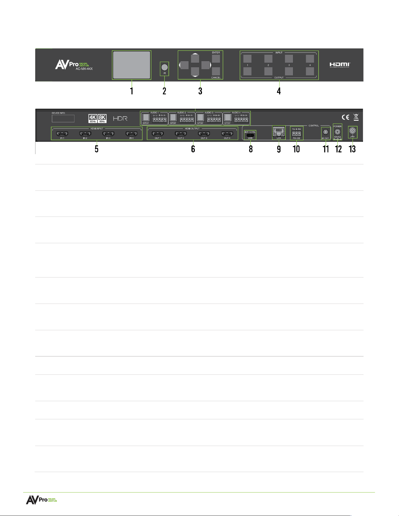
Front and Rear Panel Overview
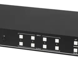
Front Panel
Rear Panel
1
Front Panel Display
• Color LED display for control and status reporting
• Control matrix switching, EDID, audio output, and network settings
2
IR Sensor
• IR Sensor for receiving signals from included IR remote control
• Remote can be used for HDMI matrix switching
3
Front Panel buttons
• Push-button controls (Up, Down, Left, Right, Enter, Cancel)
• Use buttons to navigate the front panel display menu
4
Matrix Switch buttons
• Input buttons 1 to 4, Output buttons 1 to 4
• Select Output from bottom buttons 1 to 4, then select from Input
buttons 1 to 4 to switch
5
HDMI INPUT (1-4)
• (4x) 19-pin HDMI Type-A female connector port
• HDMI source signal input connections
6
HDMI OUTPUT (1-4)
• (4x) 19-pin HDMI Type-A female connector ports
• HDMI signal output to display connections
7
SPDIF (1-4)
Balanced Audio Output (1-4)
• (4x) Digital Optical (S/PDIF) audio output ports
• (4x) Balanced stereo output 5-pin Euroblock connector ports
8
ISP / CTL USB TYPE-C
• Proprietary service port for AVPro Edge technical assistance
9
LAN
• 8-pin RJ45 female connector
• Connect to the LAN, router, or third-party control system
10
RS232
• 3-pin Euroblock connector port
11
IR Extender
• IR extension receiver port
• 3.5 mm (3-conductor)
12
Power In
• Barrel Connector
• 12 VDC / 5 A power unit

Page 10 of 35
AC-MX-44X User Manual
13
Ground
• Ground screw
• Connect the provided wire to Earth ground
Installation
Rack Mounting
The AC-MX-44X is one RU in height and may be mounted in any compatible standard 19-inch wide enclosure.
Two mounting brackets are included with the unit.
Align the holes on the mounting brackets with the holes on both sides of the rack.
1 Attach the mounting brackets to the rack with rack screws (not included).
2 Attach the mounting brackets to the rack with rack screws (not included).
Mounting Feet Assembly
Four rubber feet may be attached to the unit with the provided mounting screws.
1 Align the holes on the rubber feet with the holes underneath the unit.
2 Attach the rubber feet to the unit with the provided screws.
Page 11 of 35
AC-MX-44X User Manual
Wiring and Connections
HDMI Cables
The AC-MX-44X uses standard 19-pin HDMI female ports for inputs and output connections.
Important things to consider when planning or installing this device:
• Ensure all HDMI cables and devices support the input signal. With 8K sources, ultra-high-
bandwidth/Ultra High Speed HDMI cables rated for 48 Gbps are recommended. For 4K and lower
resolutions, High-Speed HDMI cables with Ethernet rated for 18 Gbps are sufficient if all connected
devices are rated to handle the signal.
• Ensure HDMI cables are the correct length. AVPro engineers have determined that HDMI cables 2
meters and longer help eliminate EDID and HDCP issues associated with shorter HDMI cable lengths.
USB Ports
The device also has one USB Type-C port. This is a service port intended for AVPro Edge technical support if
troubleshooting or testing is required.
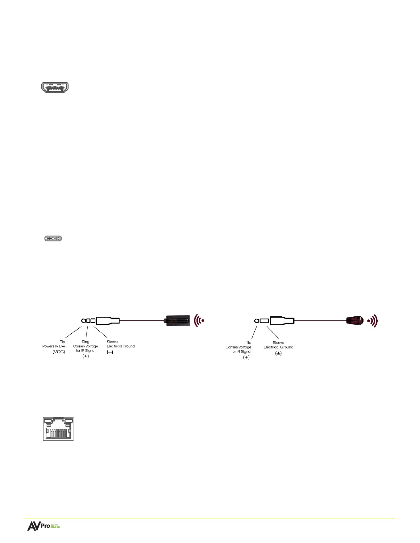
IR Wiring
IR connections are made using the provided 3.5 mm IR Emitter and IR Eye (receiver).
Ethernet/LAN
The NETWORK/LAN port on the rear panel communicates with the AC-MX-44X via a LAN, router, or third-party
control system processor and uses a standard RJ45 connector plug.
Type C
Stereo 3.5 mm (TRS) IR Eye Mono 3.5 mm (TS)
IR EmiGer
Page 12 of 35
AC-MX-44X User Manual
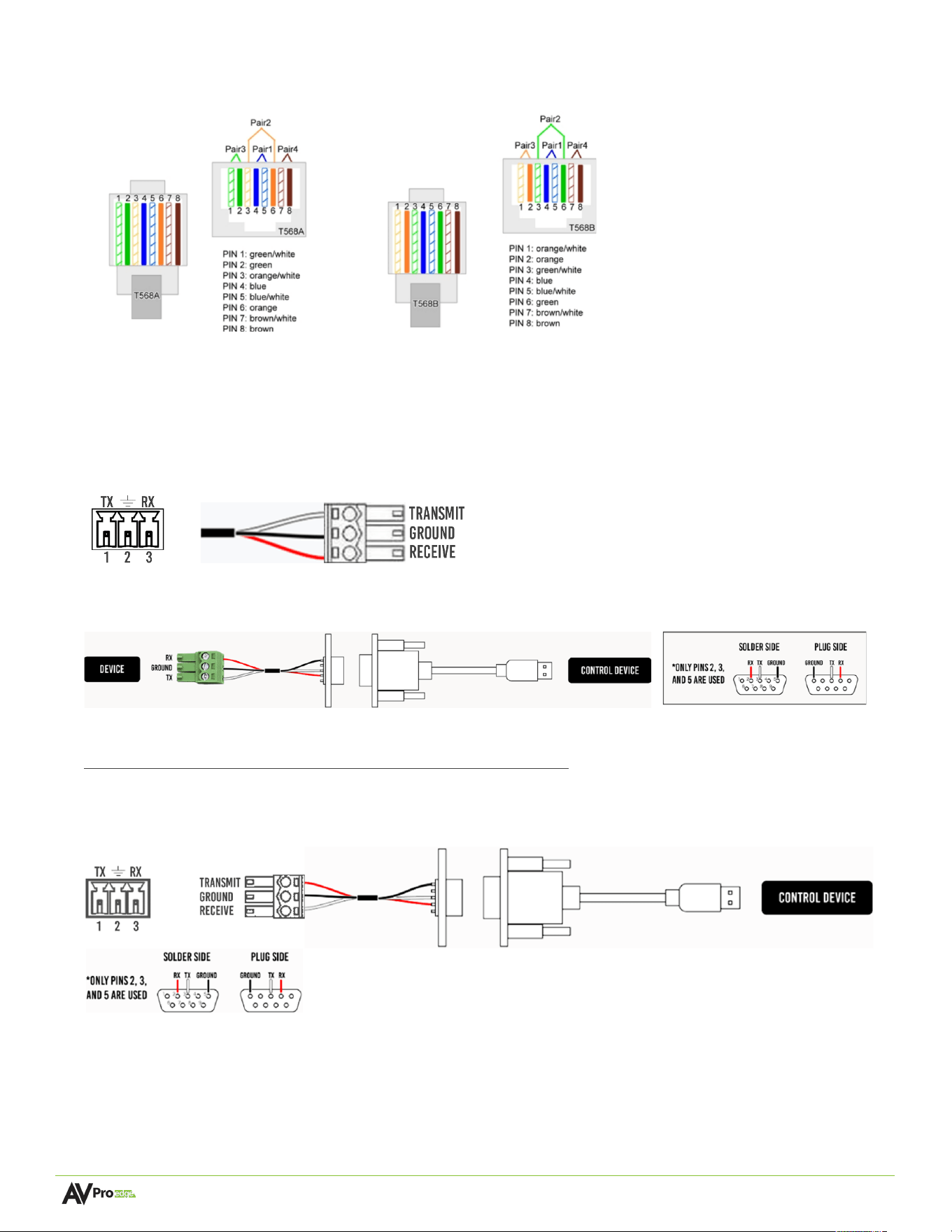
The recommended termination is based on the TIA/EIA T568A or T568B standards for the wiring of the twisted
pair cables. For TCP/IP control, commands use Telnet port 23.
RS-232 Control
The RS-232 control port on the rear panel allows a computer or third-party control system to communicate with
the AC-MX-44X.
Serial control connections are made using the provided 3-pin Euroblock connector. Insert the wire into the
appropriate hole, then secure it by tightening the screw located at the top of the connector.
Wiring for this port uses a 3-pin Euroblock-to-DB9 connector, where only pins 2, 3, and 5 are used. If the control
devices do not have a DB9 port, a USB-to-DB9 adapter may be required.
For RS-232 control, use a null modem serial cable adapter and set the serial communications to:
Baud: 57600, no parity, 8 data bits, 1 stop bit, with no handshaking.
Add a carriage return (Enter key) after each command when using direct commands. The unified command list
(ASCII) can be found here.
T568A T568B
Page 13 of 35
AC-MX-44X User Manual
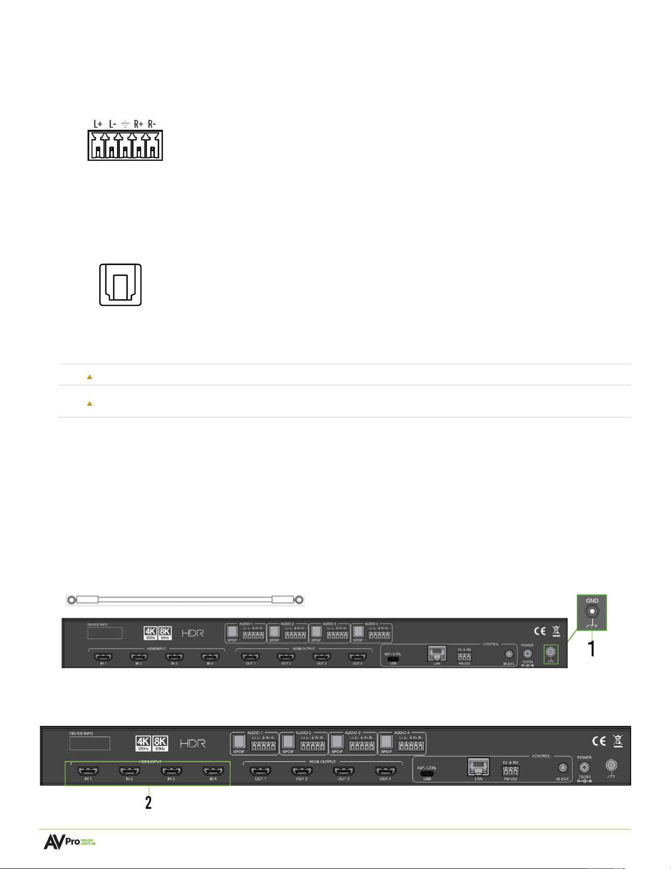
Analog Audio Output Ports
The AC-MX-44X has four 5-pin Euroblock balanced audio output ports on the unit's rear panel. These ports
output a balanced 2-channel audio signal and can be used for break-out audio to receivers and multi-zone
audio systems.
S/PDIF Audio Output Ports
The AC-MX-44X has four S/PDIF audio output ports on the unit's rear panel. These ports can output multi-
channel audio signals to receivers for surround sound or multi-zone audio systems.
AC Power Connection
Electric Shock:
Use a surge-protected circuit for all components and power supplies.
Electrical Disconnect:
The power source outlet and power supply input sockets should be easily accessible
to disconnect power in the event of an electrical hazard or malfunction.
Initial Setup
Use the steps below to connect physically to the input and output devices. For the initial setup, once all the physical
connections are made, connect the AC-MX-44X to a LAN (Local Area Network) using a control PC on the same
network and then access the Web UI.
Connecting Devices
1 Use a screwdriver to attach the yellow ground wire to the pre-installed screw on the back of the unit,
then attach the other end to a suitable grounded object.
2 Connect HDMI sources 1-4 to the HDMI Input connectors on the rear of the matrix switcher.
Analog Audio
Output
S/PDIF Audio
Output
Page 14 of 35
AC-MX-44X User Manual
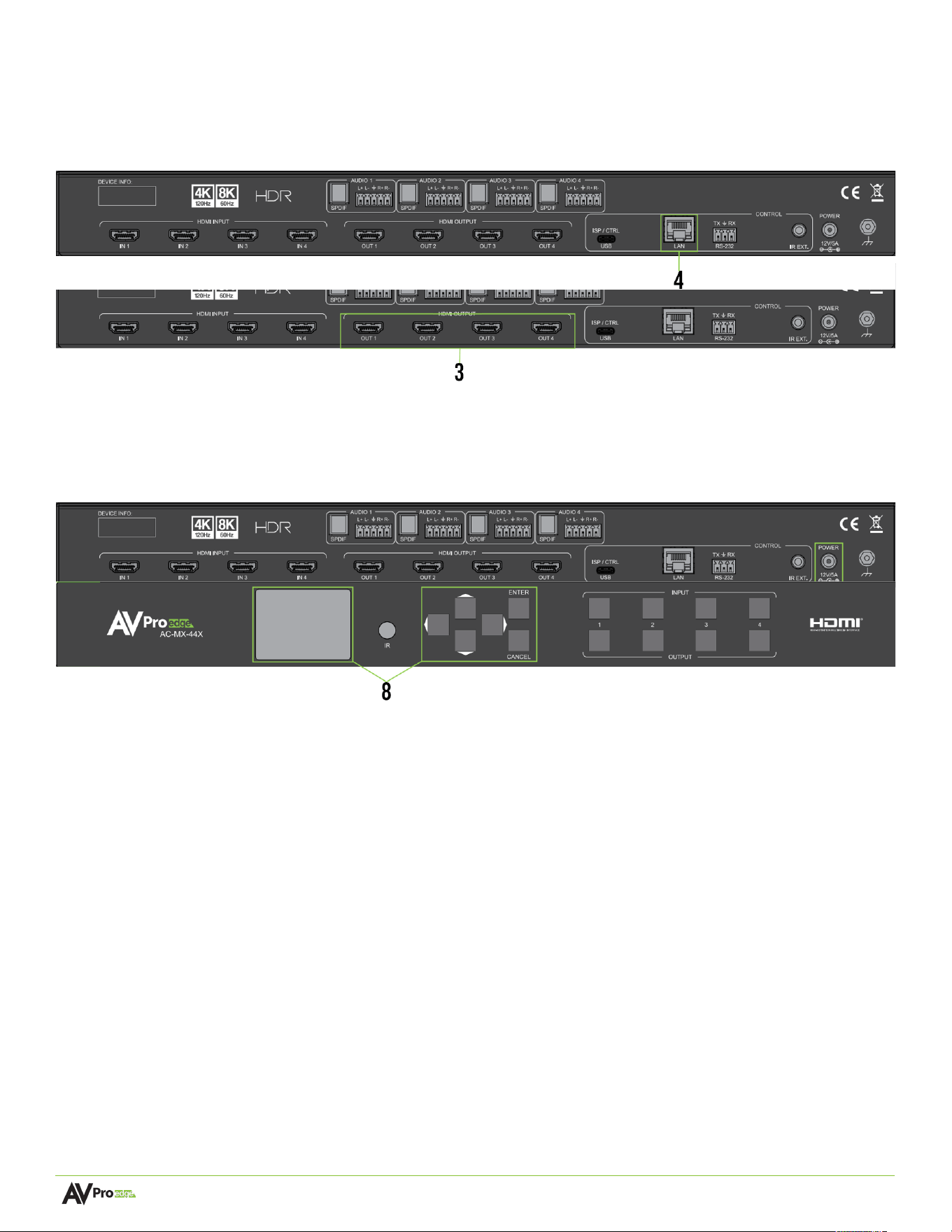
Initial Setup
3 Connect display cables 1-4 to the HDMI Output connectors on the rear of the matrix switcher.
4 Connect an RJ45 cable from the ETHERNET port of the AC-MX-44X to the LAN or a PC.
5 Power on the sources connected to the HDMI INPUT ports.
6 Power on the displays connected to the HDMI OUTPUT ports.
7 Connect the 12 VDC power supply to the POWER input port on the rear of the matrix switcher and plug
it into a suitable power source.
8 Using the front panel display and navigation buttons, select the “NETWORK” icon and push the Enter
button. The HIP IP Address shown on the front panel display can be used to access the web UI via the
browser.
Page 15 of 35
AC-MX-44X User Manual
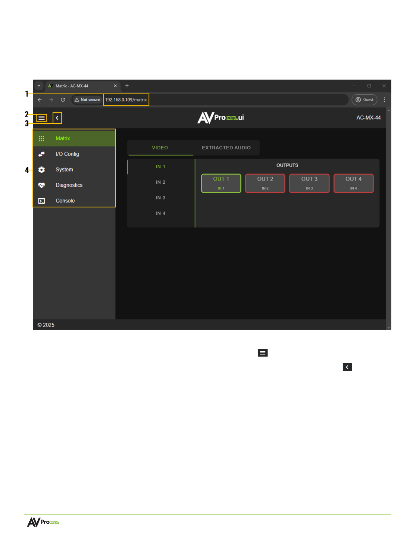
Navigating the Web UI
The AC-MX-44X features a built-in User Interface (UI) that can be accessed through a web browser for configuration
and control. Different tools and settings can be selected from the tab pages on the navigation menu column on the
left side of the screen.
1 Enter the unit IP address into a web browser like Chrome or Edge to access the Web UI.
2 To hide the navigation menu, select the hamburger menu icon .
3 Select the left arrow icon to hide the navigation menu text and show only the menu icons .
4 Select the individual tab pages from the navigation menu to navigate the different pages. This will
highlight the tab page in green to indicate the currently selected page.
Page 16 of 35
AC-MX-44X User Manual
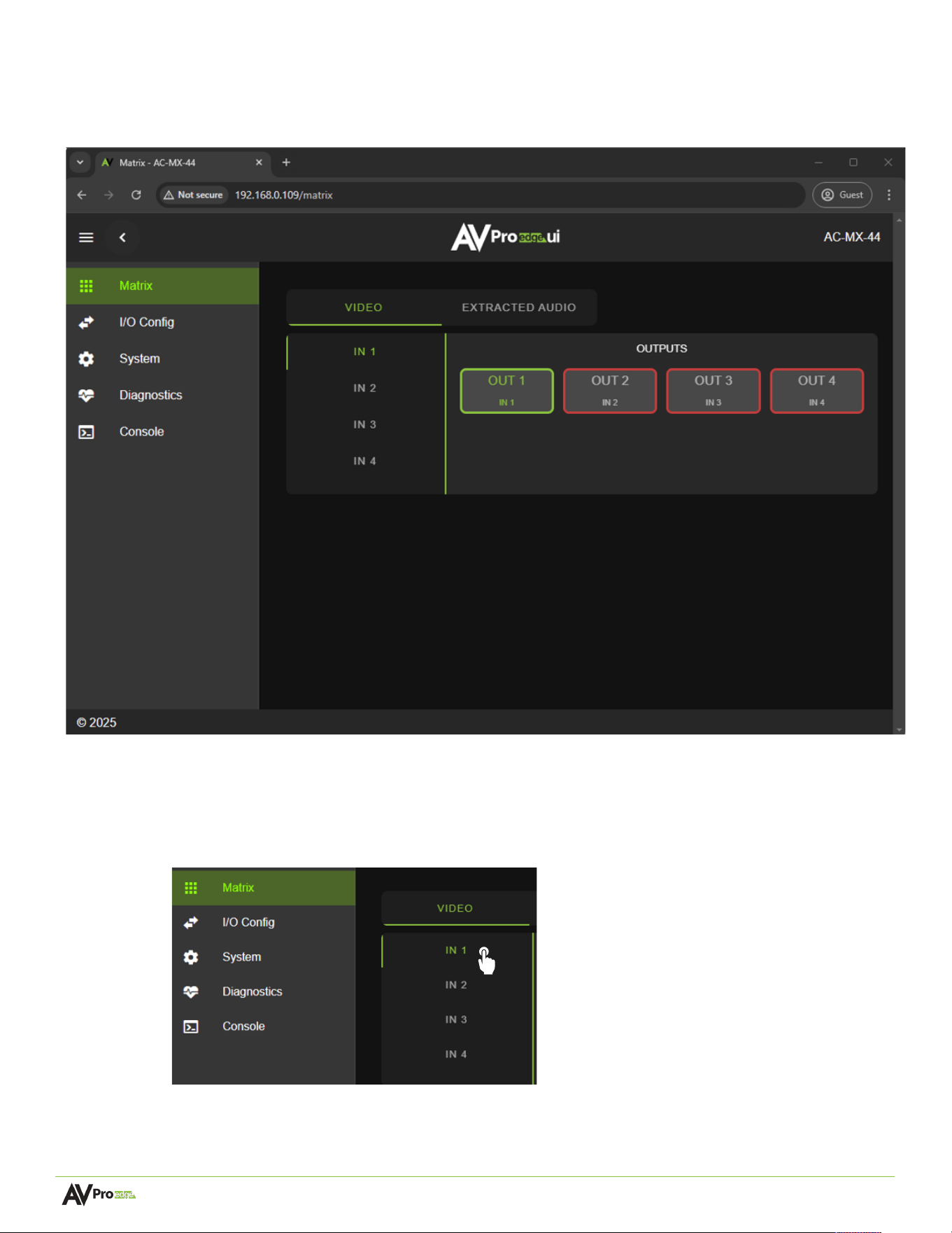
Matrix
The Matrix page layout consists of the Video Inputs column on the left and the Outputs row on the right. Each
Input and Output can be individually selected to route an HDMI input signal to a single or multiple outputs.
Video Matrix Switching
1 From the Inputs column, select a desired input. This will highlight the input with green text to
indicate a selection was made.
2 From the Outputs column, select one or multiple desired outputs to route the selected input. This
will highlight the outputs with a green border, indicating a selection was made.
Page 17 of 35
AC-MX-44X User Manual
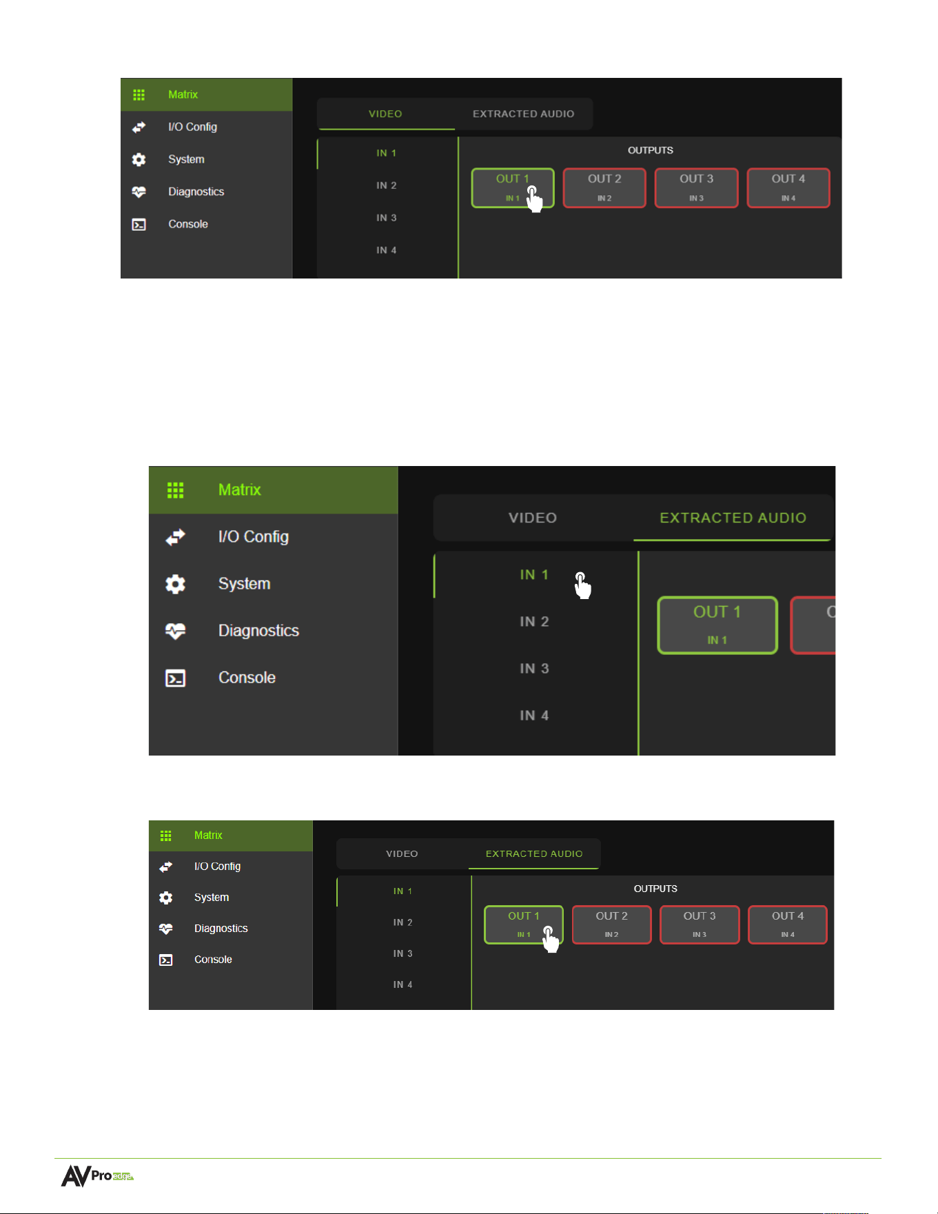
3 The selected HDMI input signal is routed to the desired output path.
Extracted Audio Matrix Switching
This menu becomes available when the Audio Mode settings are configured for Matrix.
1 . From the Inputs column, select the desired input. This will highlight the input with green text to
indicate that a selection was made.
2 From the Outputs row, select the desired output routing path. The output path is highlighted with a
green border, indicating a selection was made.
3 The selected input’s extracted audio signal is now routed to the selected output(s).
Page 18 of 35
AC-MX-44X User Manual
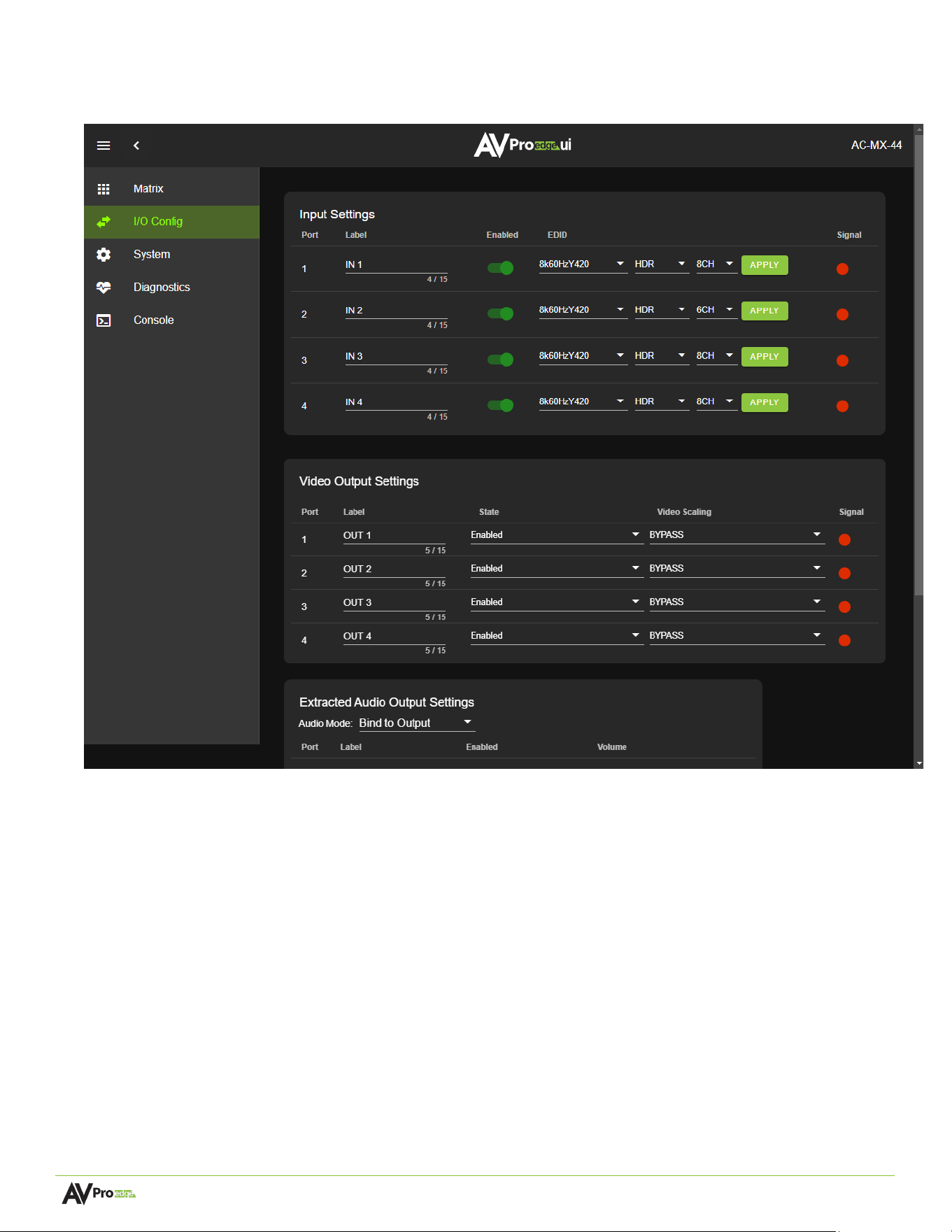
I/O Config
The I/O Config tab page features tools and settings for configuring audio and video inputs and outputs.
Page 19 of 35
AC-MX-44X User Manual
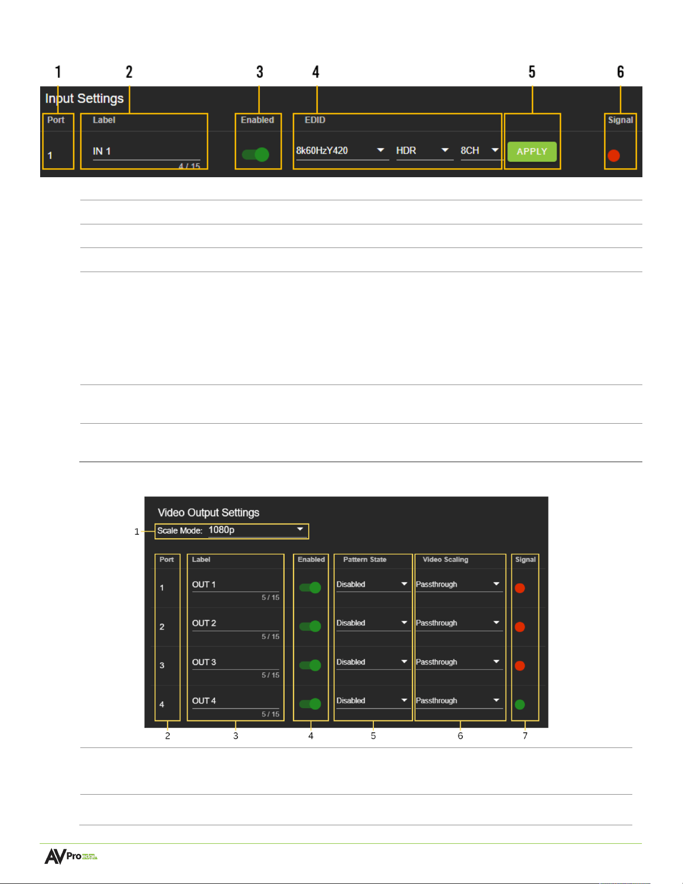
Input Se<ngs
1
Port
Indicates the HDMI input port number.
2
Label
Select the text field to enter a custom name for the input.
(
Limited to15 characters
)
3
Enabled
Select the
Enabled
toggle switch to enable (green) or disable (red) the HDMI input.
4
EDID
Select the EDID from the drop-down menu. The first drop-down group configures
resolution and refresh rate. The second drop-down group configures dynamic range,
with options for HDR or SDR. The third drop-down group configures the audio channels
with 2CH, 6CH, and 8CH options.
NOTE:
When selecting USER1, USER2, or USER3 EDID, the drop-down menus will
update, allowing the user to choose an HDMI Out to copy EDID values. Select one of the
four HDMI Outs and click the COPY button to apply (this replaces the APPLY button).
5
APPLY
This button applies the settings to the HDMI Input.
NOTE:
This button will change to COPY when selecting USER1, USER2, or USER3.
6
Signal
Shows the status of the HDMI Input. Green indicates the HDMI input has been detected;
red indicates the HDMI connection or device has not been detected.
Video Output Se<ngs
1
Scale
Mode
Use the drop-down menu to set the global scaler to downscale all scaled streams
from 8K/4K to 1080p or 8K-to-4K.
2
Port
Indicates the HDMI output port number.
Page 20 of 35
AC-MX-44X User Manual
3
Label
Select the text field to enter a custom name for the output. (Limited to 15 characters)
4
Enabled
Select the
Enabled
toggle switch to enable (green) or disable (red) the HDMI output.
5
Pattern
State
Use the drop-down to enable the test pattern selecting the resolution, 720p 60Hz,1080p
60Hz,4K 30Hz,4K 60Hz,8K 30Hz.
6
Video
Scaling
Use the drop-down menu to set the HDMI output too Passthrough or Scaled Stream
following the Scale Mode setting.
7
Signal
Shows the status of the HDMI Output. Green indicates the HDMI output has been
detected, and red indicates the HDMI output connection or device has not been
detected.
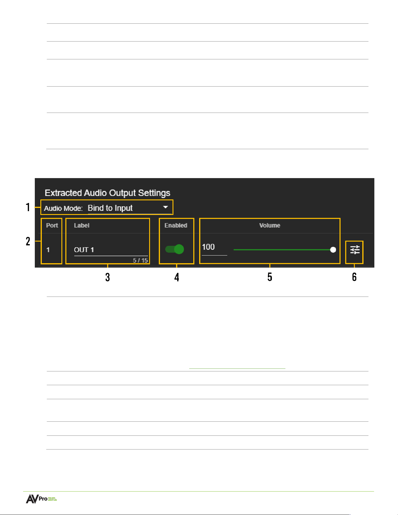
Extracted Audio Output Se<ngs
1
Audio Mode
Extracted audio ports have three distinct modes:
Bind to Input
(
Default
)
:
The audio port number corresponds to the input signal. This
mode is ideal with systems that route audio separately to a zoned amplifier.
Bind to Output
:
Audio automatically follows the HDMI Output. This mode is ideal for
a system using a local AVR for a dedicated zone.
Matrix
: Extracted audio signals are routed independently of the HDMI outputs. A new
tab on the Matrix page appears, allowing audio signal routing. An overview of this
menu can be found here: Extracted Audio Matrix Switching.
2
Port
Indicates the audio input port number.
3
Label
Select the text field to enter a custom name for the input. (
Limited to 15 characters
)
4
Enabled
Select the
Enabled
toggle switch to enable (green) or turn off (red) an extracted audio
output.
5
Volume
Adjust the volume using the slider bar or entering a value (0~100) in the text field.
6
EQ
Select to view
Audio Configuration
output
settings.
Page 21 of 35
AC-MX-44X User Manual
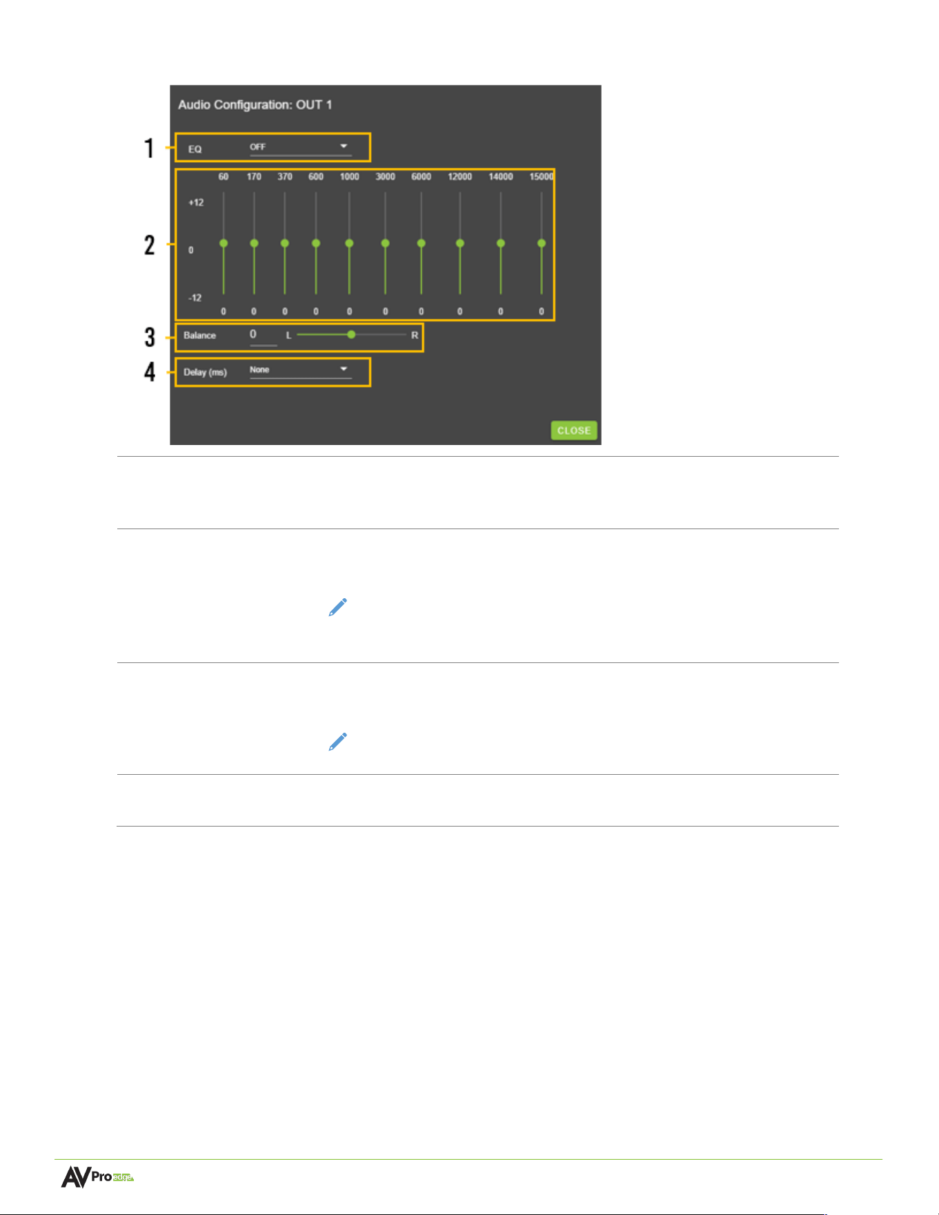
Audio ConfiguraAon
1
EQ
The dropdown menu contains a list of several preset equalizer settings
that may be applied to change the frequency response of the audio
output.
2
Frequency
Graphic depiction detailing individual frequency band equalization to the
audio signal of a particular output.
NOTE:
This graphic equalizer is intended only as a visual representation
of the individual audio frequency adjustments. Manual
adjustments cannot be made to it.
3
Balance
Adjust the Left and Right channel audio output volume by using the slider
bar or entering a value (-10 to +10) in the text field.
NOTE:
-10 is left channel weighted, 0 is balanced, and +10 is right
channel weighted.
4
Delay
(
ms
)
Adjust the delay of audio output from 0 to 630 ms. This setting addresses
lip sync issues.
Page 22 of 35
AC-MX-44X User Manual
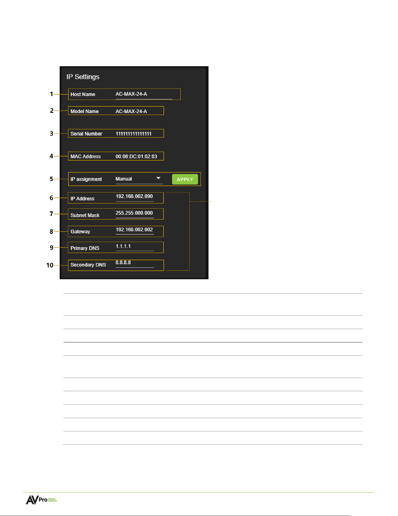
When the IP Assignment is set to Automatic,
these will be assigned by a DHCP reservation
from the router, or they can be manually
entered when the IP Assignment is set to Manual.
Select the Apply button when manually entering
the IP Assignment, IP Address, Subnet Mask,
Gateway, Primary DNS, and Secondary DNS for
changes to take effect.
System
IP Se<ngs
1
Host Name
Select the text field to enter a custom name for the unit. The
default shows its model number.
2
Model Name
Shows the AVPro Edge model number.
3
Serial Number
Shows the unique serial number.
4
MAC Address
Shows the unique MAC address.
5
IP Assignment
Select the dropdown menu to set the unit’s IP mode to
DHCP
(default) or
Manual
(
Static IP
), then select the
Apply
button.
6
IP Address
Shows the IP address.
7
Subnet Mask
Shows the subnet mask.
8
Gateway
Shows the default gateway.
9
Primary DNS
Shows the primary domain name server.
10
Secondary DNS
Shows the secondary domain name server.
Page 23 of 35
AC-MX-44X User Manual
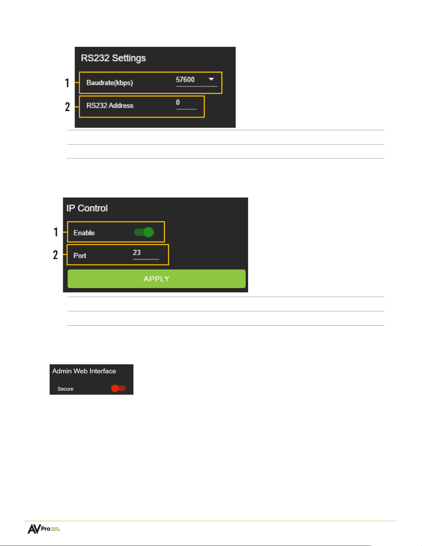
RS-232 Se<ngs
1
Baudrate
(
kbps
)
Select the drop-down menu to set the RS-232 Baudrate.
2
RS232 Address
Shows the unit
’
s RS-232 address, from 0-99.
IP Control
1
Enable
Select the toggle switch to turn IP/TCP control on or off.
2
Port
Select the text field to set the Telnet port. Default is Telnet port 23.
Admin Web Interface
Select the Secure toggle switch to enable (green) or to turn off (red). When enabled, the username and
password can be changed.
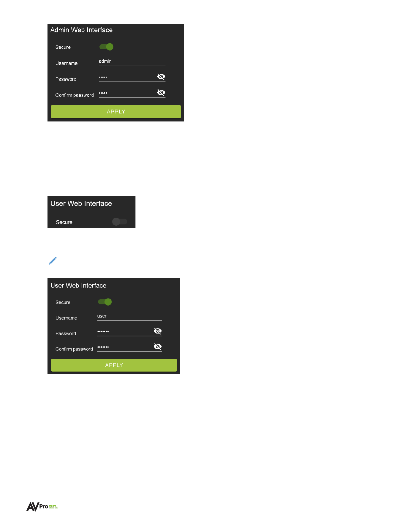
Page 24 of 35
AC-MX-44X User Manual
With the Admin Web Interface enabled, the only menu that will be accessible on the Web UI will be the
Matrix tab page. The rest of the settings will require the Admin login.
Default username: admin
Default password: admin
User Web Interface
Select the Secure toggle switch to enable (green) or turn off (grey). When enabled, the username and
password can be changed.
NOTE:
The
Admin Web Interface
must first be enabled before this setting can be changed.
With the Admin and User Web Interfaces enabled, the Web UI's menus are inaccessible without first logging
in.
After logging in with the User credentials, the only menu accessible on the Web UI will be the Matrix tab
page. The rest of the settings will require the Admin login.
Default username: user
Default password: user123
Page 25 of 35
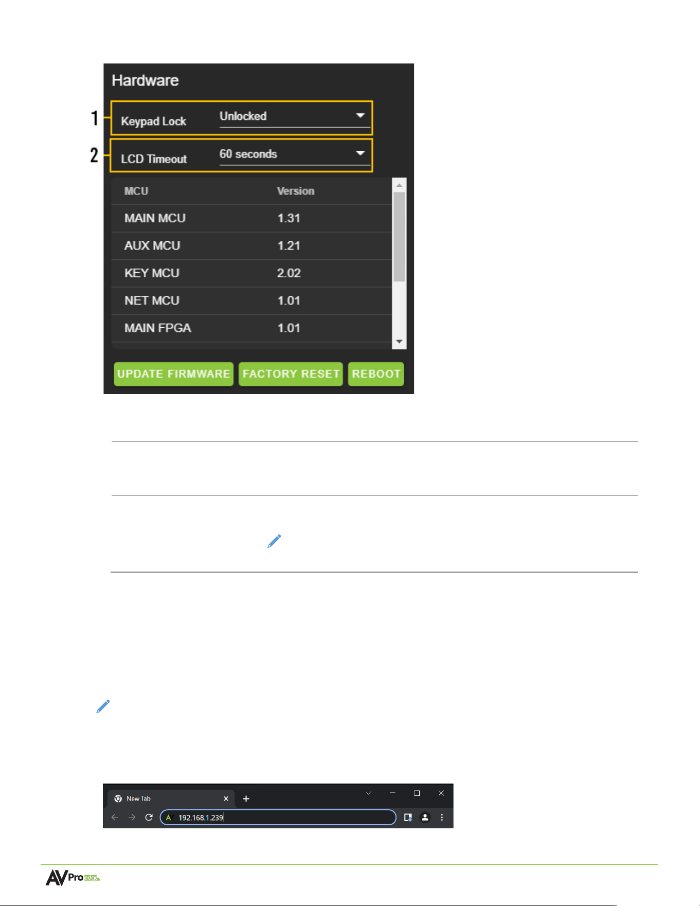
AC-MX-44X User Manual
Hardware
This section shows the unit’s current firmware versions and provides options for updating firmware, factory
resetting, and rebooting the unit.
1
Keypad Lock
Select the drop-down menu to select Unlocked to allow use of the front
panel display and buttons or Locked to turn off the front panel display
and buttons.
2
LCD Timeout
Select the drop-down menu to select the interval at which the LCD will
power off due to inactivity.
NOTE:
Setting the LCD Timeout to Always On may shorten the
lifespan of the LCD screen or result in image burn-in.
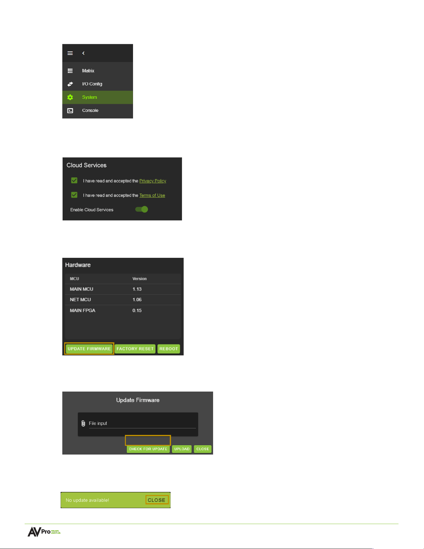
Cloud Services and Firmware Updates
Cloud Services allows OTA (Over-the-Air) firmware updates to be performed on the unit. This allows the unit
to search the Cloud for the latest firmware versions and enable third-party remote management services. If
the Cloud Services setting is turned off, the unit will opt out of any previously enabled services and will not be
able to access OTA firmware updates.
NOTE:
When updating firmware, some settings and configurations may revert to their original factory
default settings and may need to be re-applied after the updates are complete. It is always recommended
that settings and configurations are backed up before updating firmware.
1 Enter in the unit’s IP address into a Chrome or Edge web browser to access the unit’s Web UI.
Page 26 of 35
AC-MX-44X User Manual
2 Navigate to the System tab page.
3 Review the Privacy Policy and Terms of Use in the Cloud Services section, then check both boxes and
select Enable Cloud Services toggle setting
IMPORTANT:
This is required for the unit to perform OTA
firmware updates.
4 In the Hardware section, select the Update Firmware button. A new dialog box will open.
5 In the Update Firmware dialog box, select Check for Update. The unit will now check the Cloud for
available firmware updates.
6 If the current firmware version is the latest, a notification window will prompt the message “No update
available!” at the top of the page. Select the Close button.
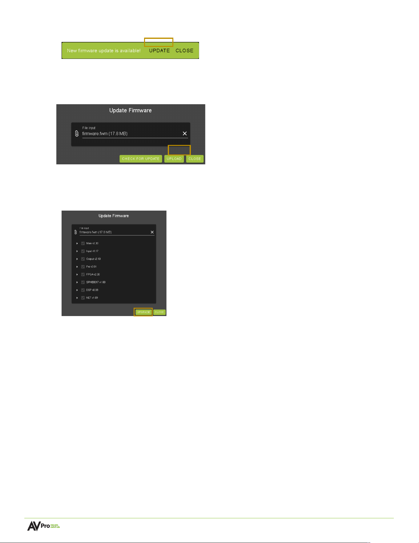
7 If a newer version of firmware is detected from the Cloud, a notification window will prompt the message
Page 27 of 35
AC-MX-44X User Manual
“New firmware update is available!”. Select the Update button.
8 A new firmware file will automatically populate into the File input field from the Cloud. Select the Upload
button.
9 From this screen, a newer firmware version is displayed before installation. Select the Upgrade button.
The unit will then begin installing the latest firmware version. DO NOT refresh the webpage or power off
the unit during the update!
10 Once the progress bar reaches 100%, select the Close button. Once the firmware updates are complete,
the unit will automatically reboot. After the unit reboots, refresh the webpage.
Page 28 of 35
AC-MX-44X User Manual
Diagnostics
The Diagnostics menu is designed to troubleshoot issues with EDID, HDMI sources, and HDMI displays. HDMI
connections can be reset, and valuable information about the source and sink devices can be obtained from
the status menus.
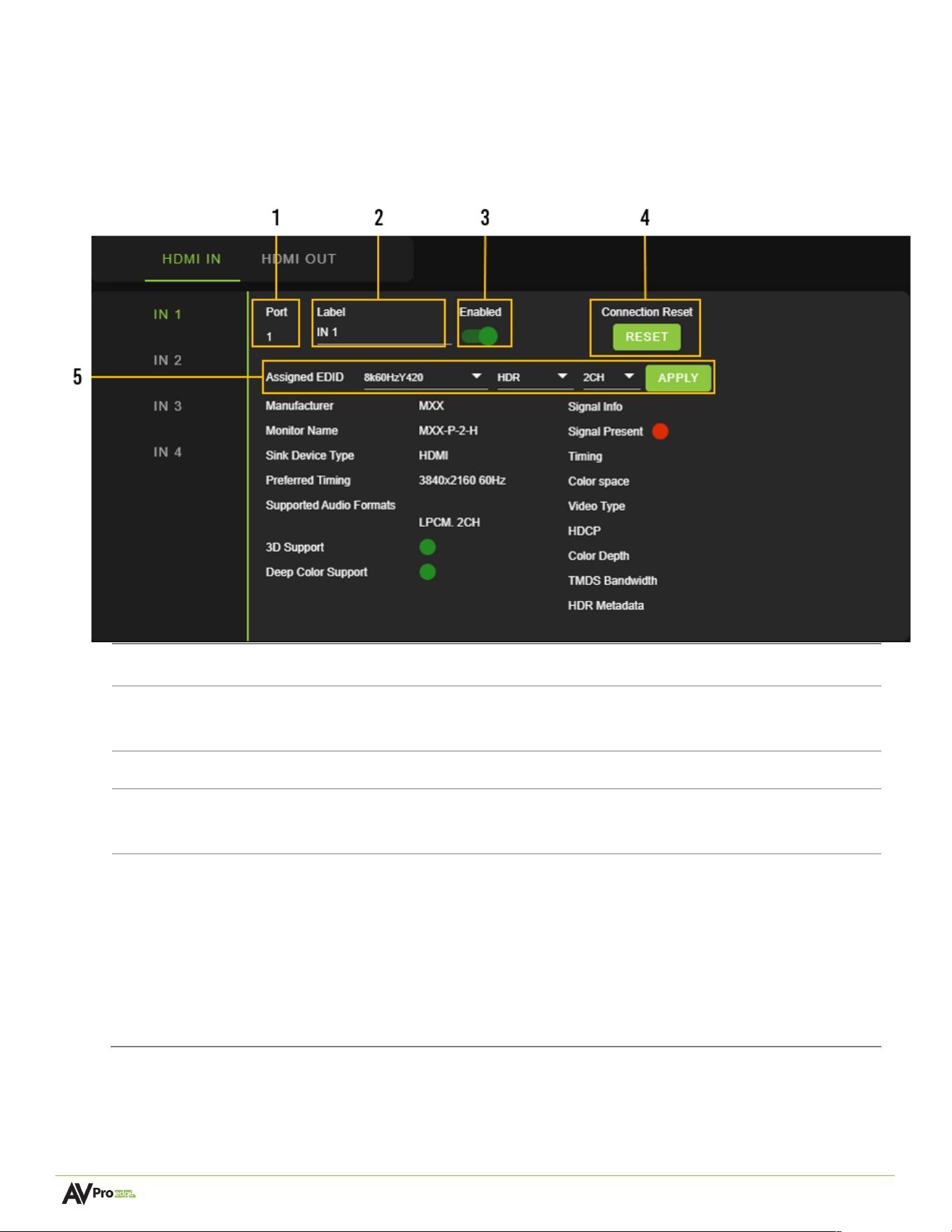
HDMI Inputs
1
Port
Indicates the HDMI output port number.
2
Label
Select the text field to enter a custom name for the output. (Limited to 15
characters)
3
Enabled
Select the
Enabled
toggle switch to enable (green) or turn off (red) the HDMI input.
4
Connection
Reset
Select the RESET button to reset the HDMI input.
5
EDID
Select the EDID from the drop-down menu. The first drop-down group configures
resolution and refresh rate. The second drop-down group configures dynamic
range, with options for HDR or SDR. The third drop-down group configures the
audio channels with 2CH, 6CH, and 8CH options.
NOTE:
When selecting USER1, USER2, or USER3 EDID, the drop-down menus will
update, allowing the user to choose an HDMI Out to copy EDID values. Select one of
the four HDMI Outs and click the COPY button to apply (this replaces the APPLY
button).
Page 29 of 35
AC-MX-44X User Manual
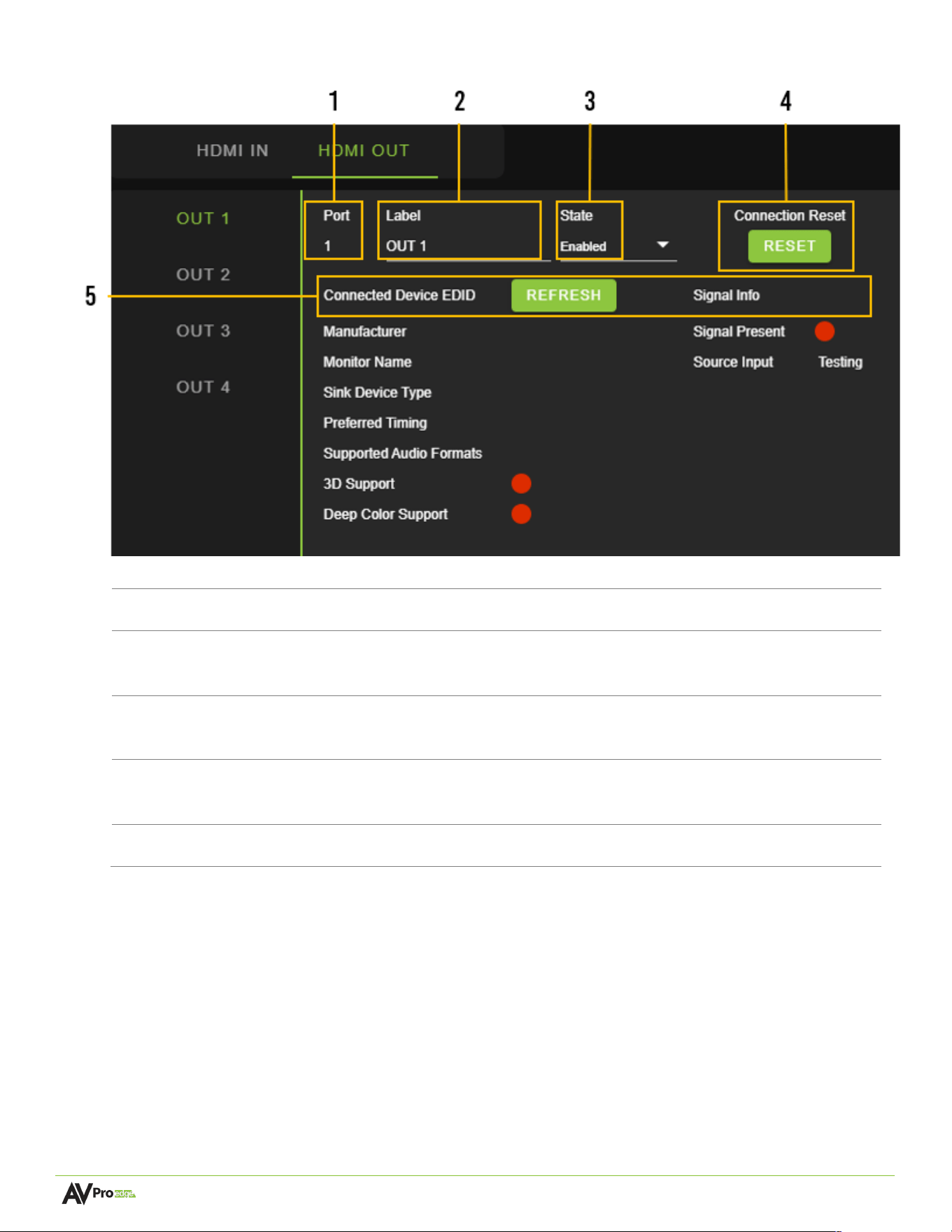
HDMI Outputs
1
Port
Indicates the HDMI output port number.
2
Label
Select the text field to enter a custom name for the output. (Limited to 15
characters)
3
State
You can use the drop-down menu to turn the HDMI output on or off or
generate a test pattern at various resolutions and refresh rates.
4
Connection
Reset
Select the RESET button to reset the HDMI input connection.
5
Refresh
Click the REFRESH button to poll the sink device (display) for EDID information.
Page 30 of 35
AC-MX-44X User Manual
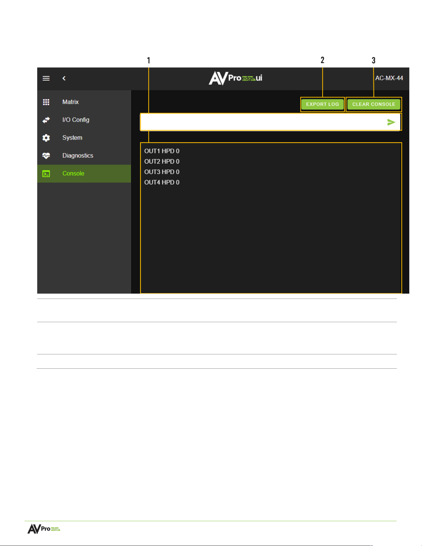
Console
The Web UI features a built-in command console, allowing API commands to be sent directly to the unit.
1
Text Field
Enter API commands into this field. System events generated by the unit will be recorded
continuously while the
Console
tab page is open within the Web UI.
2
Export Log
Select to download a .txt file of the information recorded by the console log. The console
log only records unit information when the Web UI is opened to the
Console
tab page and
does not record or store information internally.
3
Clear Console
Select to clear the information recorded in the console log.

Page 31 of 35
AC-MX-44X User Manual
Command-List
Command
Action
H
Help
STA
Show Global System Status
SET RST
Reset to Factory Defaults
SET RBT
System Reset to Reboot
SET ADDR xx
Set System Address to xx {xx = [00~99] (00 = Single)}
SET BAUDR x
Set System BaudRate to x {x = [0~5] (0=9600,1=14400,2=19200,3=38400,4=57600,5=115200)}
SET LCD ON Tx
Set LCD Remain On Time {x = [0~3] (0 = Always ON, 1 = 15, 2 = 30, 3 = 60 Sec)}
SET KEY LOCK ON/OFF
Set Key Lock On/Off
GET ADDR
Get System Address
GET STA
Get System Status
GET BAUDR
Get System BaudRate
GET INx SIG STA
Get Input x Signal Status {x = [0~4] (0 = ALL)}
GET OUTx SIG STA
Get Output x Signal Status {x = [0~4] (0 = ALL)}
GET OUTx HPD
Get HDMI Output x HPD Status {x = [0~4] (0 = ALL)}
GET INx VID FMT INF
Get Input x Video Format Info {x = [0~4] (0 = ALL)}
GET LCD ON T
Get LCD Remain On Time
GET KEY LOCK
Get Key Lock Status
Output Setup Commands:
(
Note: output number
(
x
)
=HDMI,x=[1-4]
)
SET OUTx VS INy
Set Output x to Input y {x = [04] (0 = ALL), y = [14]}
SET OUTx SGMT y
Set Output Signal Generator Timing {x = [0~4] (0 = ALL), y = [0~5] (0 = OFF, 1 = 1080p 60Hz, 2
= 4K 30Hz, 3 = 4K 60Hz, 4 = 4K 120Hz, 5 = 8K 30Hz)}
SET OUTx VIDEOy
Set Output VIDEO Mode {x=[0~4](0=ALL), y=[0~1](0=Bypass,1=Scaled)}
SET GSCALE VFMTx
Set Global Scale Vfmt {x=[0~1](0=8K/4K->2K,1=8K->4K)}
SET OUTx EXA EN/DIS
Set Ex-Audio Output Enable/Disable {x = [0~4] (0 = ALL)}
SET OUTx EXADL PHy
Set Ex-Audio Delay {x = [0~4] (0 = ALL), y = [0~7] (0 = Bypass, 1~7 =
90,180,270,360,450,540,630 ms)}
SET EXAMX MODEx
Set Ex-Audio Matrix Mode {x = [0~2] (0 = Bind to Output, 1 = Bind to Input, 2 = Matrix)}
SET OUTx AS INy
Set Ex-Audio Output x to Input y {x = [0~4] (0 = ALL), y = [1~4]}
SET OUTx EXAUD LEVy
Set Output x EQ-Audio Volume Level y {x = [0~4] (0 = ALL), y = [0~100]}
SET OUTx EXA LVLy
Set Output x Ex-Audio (Balanced) Left Volume Level y {x = [0~4] (0 = ALL), y = [0~10]}
SET OUTx EXA RVLy
Set Output x Ex-Audio (Balanced) Right Volume Level y {x = [0~4] (0 = ALL), y = [0~10]}
SET OUTx EXEQ MODEy
Set Output x EX-Audio Volume EQ Mode y {x = [0~4] (0 = ALL), y = [0~7]} (0 = OFF, 1 =
Classical, 2 = Headphone, 3 = Hall, 4 = Live, 5 = Pop, 6 = Rock, 7 = Vocal)
SET OUTx STREAM ON/OFF
Set Output x Stream ON/OFF {x = [0~4] (0 = ALL)}
GET OUTx VS
Get Output x Video Route {x = [0~4] (0 = ALL)}
GET OUTx VIDEO
Get HDMI Output x Video Mode{x=[0~4 ](0=ALL)}
GET GSCALE VFMT
Get Global Scale Vfmt
GET OUTx SGMT
Get Output Signal Generator Timing Status {x = [0~4] (0 = ALL)}
GET OUTx EXA
Get Ex-Audio Output Enable/Disable Status {x = [0~4] (0 = ALL)}
GET OUTx EXADL PH
Get Ex-Audio Output Delay Status {x = [0~4] (0 = ALL)}
GET EXAMX MODE
Get Ex-Audio Matrix Mode
GET OUTx AS IN
Get Output x Ex-Audio Route {x = [0~4] (0 = ALL)}
GET OUTx EXAUD LEV
Get Output x EQ-Audio Volume Level {x = [0~4] (0 = ALL)}
GET OUTx EXA LVL
Get Output x Ex-Audio (Balanced) Left Volume Level {x = [0~4] (0 = ALL)}
GET OUTx EXA RVL
Get Output x Ex-Audio (Balanced) Right Volume Level {x = [0~4] (0 = ALL)}
GET OUTx EXEQ MODE
Get Output x EX-Audio Volume EQ Mode Status {x = [0~4]
(
0 = ALL
)
}

Page 32 of 35
AC-MX-44X User Manual
GET OUTx STREAM
Get Output x Stream ON/OFF Status {x = [0~4] (0 = ALL)}
GET OUTx EDID DATA
Get Output x EDID Data {x = [1~4]}
GET OUTx CRC VAL
Get Output x CRC Value {x = [0~4] (0 = ALL)}
Input Setup Commands:
(
Note:input number
(
x
)
=HDMI
(
x
)
,x=[1-4]
)
SET INx EDID y
Set Input x EDID{x=[0~4](0=ALL), y=[0~23](None:[18~20])}
0. 1080P_2CH_SDR
1. 1080P_6CH_SDR
2. 1080P_8CH_SDR
3. 4K60Hz_2CH
4. 4K60Hz_6CH
5. 4K60Hz_8CH
6. FRL3_4K120Hz_Y420_2CH
7. FRL3_4K120Hz_Y420_6CH
8. FRL3_4K120Hz_Y420_8CH
9. FRL3_8K30Hz_Y420_2CH
10. FRL3_8K30Hz_Y420_6CH
11. FRL3_8K30Hz_Y420_8CH
12. FRL5_4K120Hz_10b_2CH
13. FRL5_4K120Hz_10b_6CH
14. FRL5_4K120Hz_10b_8CH
15. FRL5_8k60Hz_Y420_2CH
16. FRL5_8k60Hz_Y420_6CH
17. FRL5_8k60Hz_Y420_8CH
21. USER1_EDID
22. USER2_EDID
23. USER3_EDID
SET INx EDID CY OUTy
Copy Output y EDID To Input x(USER1 BUF){x=[0~4](0=ALL), y=[1~4]}
SET INx Uy EDID CY OUTz
Copy Output z EDID To User y Buff Input x{x=[0~4](0=ALL), y=[1~3],z=[1-4]}
SET INx EDID Uy DATAz
Write EDID To User y Buffer of Input x{x=[0~4](0=ALL), y=[1-3],z=[EDID Data]}
SET INx TMDS ON/OFF
Set Input x Port Power Status ON/OFF {x = [0~4] (0 = ALL)}
GET INx EDID
Get Input x EDID Index {x = [0~4] (0 = ALL)}
GET INx EDID y DATA
Get Input x EDID y Data {x = [1~4] (0 = ALL), y = [0~23]}
GET INx TMDS
Get Input x Port Power Status {x = [0~4] (0 = ALL)}
Network Setup Command:
(
xxx=[000-255], zzzz=[0001~9999]
SET RIP xxx.xxx.xxx.xxx
Set Route IP Address to xxx.xxx.xxx.xxx
SET HIP xxx.xxx.xxx.xxx
Set Host IP Address to xxx.xxx.xxx.xxx
SET NMK xxx.xxx.xxx.xxx
Set Net Mask to xxx.xxx.xxx.xxx
SET TIP zzzz
Set TCP/IP Port to zzzz
SET DHCP y
Set DHCP {y = [0~1]
(
0 = Disable, 1 = Enable
)
}
GET RIP
Get Route IP Address
GET HIP
Get Host IP Address
GET NMK
Get Net Mask
GET TIP
Get TCP/IP Port
GET DHCP
Get DHCP Status
GET MAC
Get MAC Address
IR Code Setup Command:
SET IR SYS xx.yy
Set IR Custom Code {xx = [00-FFH], yy = [00-FFH]}
SET IR OUTx INy CODE zz
Set IR Data Code {x = [1~4], y = [1~4], zz = [00-FFH]}
GET IR SYS
Get IR Custom Code
GET IR OUTx INy CODE
Get IR Data Code {x = [1~4], y = [1~4]}

Page 33 of 35
AC-MX-44X User Manual
Troubleshooting
• Verify Power – Ensure the power supply is connected correctly and on an active circuit.
• Verify Connections – Ensure all cables are securely connected and properly terminated.
• Verify Current Versions—Ensure that any firmware/software/driver updates are available for the devices.
• No Sound—Verify that the signal being sent is compatible with the connected devices in the signal chain.
Ensure the device’s volume level is properly adjusted and not set to mute. If a signal is present from the
input source, the selected output(s) will have a visible red optical light that can be seen from the TOSLINK
port.
• Static, Buzzing, or Humming Noises - Use shielded RCA cables between the AC-MX-44X and analog devices
to reduce noise. Make sure the matrix is grounded to metal components like racks or conduit. This helps
prevent ground loops, which can cause unwanted audio buzzing or humming.
Maintenance
Please observe the following instructions to ensure the reliable operation of this product and protect the safety of
any person using or handling this device while powered.
• Use the provided power supply. If an alternate supply is required, check its voltage and polarity to ensure
that it has sufficient power to supply the device.
• Do not operate these products outside the specified temperature and humidity range in the above
specifications.
• Ensure there is adequate ventilation to allow this product to operate efficiently.
• Equipment repair should only be carried out by qualified professionals, as these products contain sensitive
components easily damaged by mistreatment.
• Only use this product in a dry environment. Do not allow any liquids or harmful chemicals to come into
contact with these products.
• Clean this unit with a soft, dry cloth. Never use alcohol, paint thinner, or benzene for cleaning.
Damage Requiring Service
The unit should be serviced by qualified service personnel if:
• The DC power supply cord or AC adapter has been damaged
• Objects or liquids have gotten into the unit
• The unit has been exposed to rain
• The unit does not operate normally or exhibits a marked change in performance
• The unit has been dropped, or the housing damaged
Support
If you experience any problems while using this product, refer to the Troubleshooting section of this manual before
contacting Technical Support. When calling, the following information should be provided:
• Product name and model number

Page 34 of 35
AC-MX-44X User Manual
• Product serial number
• Details of the issue and any conditions under which the issue is occurring
• Clean this unit with a soft, dry cloth. Never use alcohol, paint thinner, or benzene to clean this unit.
Warranty
The Basics
AVPro Edge warranties its products purchased from Authorized AVPro Edge Resellers or direct purchases.
Products are guaranteed free from manufacturing defects and in sound physical and electronic condition.
AVPro Edge has developed a warranty that anyone can support. We wanted to remove all the “red tape” from a
warranty and make it simple. Our 10-year NO-BS warranty hinges on three elements:
• If you are having trouble, call us. We will attempt to troubleshoot your issue over the phone.
• If it’s broken, we will replace it in advance on our dime and cover the return shipping. Repair is an
option, too, but that is YOUR call.
• We know you know what you are doing. We will not make you go through unnecessary steps to
troubleshoot an extender…
Coverage Details
AVPro Edge will replace or repair (at the customer's choice) any defective product within the warranty period. If
the product is out of stock or on backorder, it can be replaced with a comparable product of equal value/feature
set (if available) or repaired.
Your warranty begins upon receipt of the product (as confirmed by the shipping firm's tracking). If tracking
information is unavailable, the warranty will commence 30 ARO (After Receipt of Order). The coverage continues
for 10 years.
Red Tape
AVPro Edge is not responsible for untraceable purchases or those made outside an authorized channel.
If we conclude that a product or serial number has been tampered with, as identified by the warranty seal or
physical examination, the warranty will be void. Additionally, excessive physical damage (beyond normal wear
and tear) may result in the warranty being voided or prorated based on the extent of the damage, as examined
by an AVPro Edge representative.
Damage caused by “acts of God” is not covered. These can include natural disasters, power surges, storms,
earthquakes, tornadoes, sinkholes, typhoons, tidal waves, hurricanes, or any other uncontrollable event related
to nature.
Damage caused by incorrect installation will not be covered. Examples include an incorrect power supply,
inadequate cooling, improper cabling, inadequate protection, and static discharge.
The Authorized AVPro Edge Reseller will service products installed or sold by a third party to AVPro Edge. The
warranty does not include accessories (IR Cables, RS-232, Power Supplies, etc.). We will make acceptable efforts
to source and supply replacements for defective accessories at a discounted rate as needed.

Page 35 of 35
AC-MX-44X User Manual
Obtaining an RMA
Dealers, Re-sellers, and Installers can request an RMA from the AVPro Edge Tech Support Rep or their Sales
Engineer.
You may also email [email protected] or fill out the general contact form at avproedge.com/contact
End users may not request an RMA directly from AVPro Edge and will be referred back to the Dealer, Re-seller,
or Installer.
Shipping
For the USA (not including Alaska and Hawaii). Shipping is covered on advanced replacements for FedEx Ground
(some expressed exceptions may apply). Defective product return shipping is covered by AVPro Edge using an
emailed return label. Items must be returned within 30 days of receipt of the replacement product; after 30
days, the customer will be billed. Other return shipping methods will not be covered.
The returnee will be responsible for the shipping costs for International (and Alaska and Hawaii) returns. Once
the unit is scanned for return shipping, AVPro Edge will ship the new unit for replacement.
Limitation on Liability
AVPro Global Holdings LLC's maximum liability under this limited warranty shall not exceed the actual purchase
price paid for the product. AVPro Global Holdings LLC is not responsible for direct, special, incidental, or
consequential damages resulting from any breach of warranty or condition or under any other legal theory to
the maximum extent permitted by law. Taxes, Duties, VAT, and freight forwarding service charges are not
covered or paid for by this warranty.
This warranty does not cover obsolescence or incompatibility with newly invented technologies (after the
product's manufacture).
Obsolescence is defined as:
“Peripherals are rendered obsolete when current technology does not support product repair or re-
manufacture. Obsolete products cannot be re-manufactured because advanced technologies supersede original
product manufacturer capabilities. Product redevelopment is not an option because of performance, price, and
functionality issues.”
Discontinued or out-of-production items will be credited toward a current product of equal or comparable
capabilities and cost at fair market value. AVPro Edge determines fair market value.
Exclusive Remedy
This limited warranty and the remedies above are exclusive to the maximum extent law permits, instead of all
other warranties, remedies, and conditions, whether oral or written, express or implied. To the maximum extent
permitted by law, AVPro Global Holdings LLC expressly disclaims any implied warranties, including, without
limitation, warranties of merchantability and fitness for a particular purpose. If AVPro Global Holdings LLC
cannot lawfully disclaim or exclude implied warranties under applicable law, all implied warranties covering this
product, including merchantability and fitness for a particular purpose, shall apply to this product as provided
under applicable law.
This warranty supersedes all other warranties, remedies, and conditions, whether oral or written, express or
implied.