
34
24 (4x)
23
47
46
3g
3d
3e
45
6
44
38b
39
40
41
38a
43c
42
43a
43d
43b
3a
3b
1(4x)
3c
5a
38a
38b
38
43a 43b
43c 43d
43
39 40
41
52
3f
5b
5c
4
5d
6 (4x)
7 (4x)
5a 5b 5c
5d 5e 46
5
2
13
22
30 (2x)
31b
1 (1x)
37 (1x)
35 (2x)
1 (2x)
32b
31a
31a
31b
31
29
28 (2x)
27 (2x)
32a
3a 3b 3c 3d
3e 3f 3g
3
6 44
45
56
1 32a 32b
35 37
32
48
33
26 25
8
9
10
8
9
23
24
57
5e
15
16
17
18
19
21
15 16
17 18
50
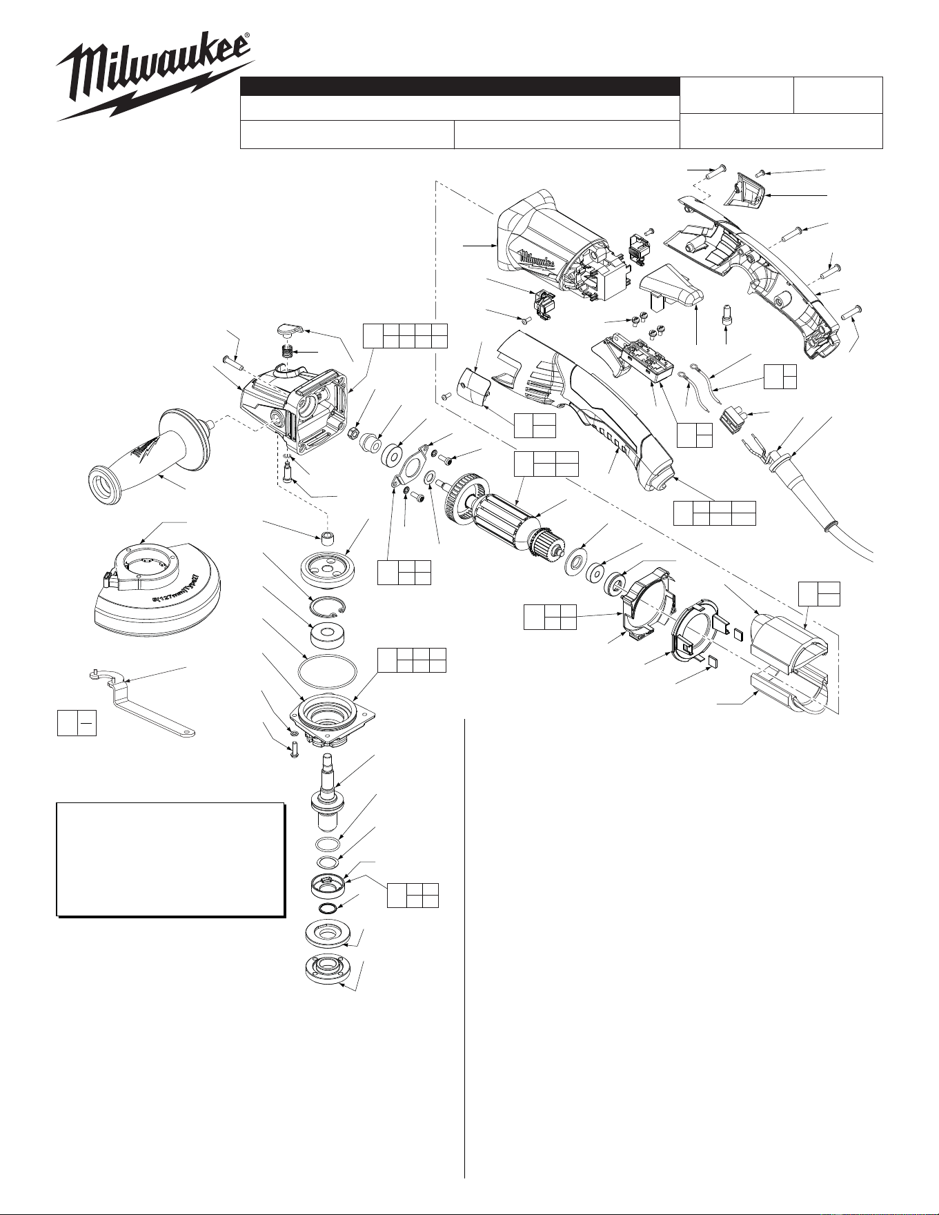
*LUBRICATION NOTE:
When servicing the Gears (5a & 46)
or the Gearcase (3c), 90-95% of the
old grease must be removed prior
to new grease being added.
FIG. LUBRICATION*
5a,46 Type "Y" Grease, No. 49-08-5270,
Must Be Applied To All Gear Teeth.
EXAMPLE:
Component Parts (Small #)
Are Included When Ordering
The Assembly (Large #).
0
00
FIG. PART NO. DESCRIPTION OF PART NO. REQ.
27 05-88-0030 M3 x 8.5mm Pan Hd. ST Screw T-10 (2)
28 22-18-2240 Carbon Brush Assembly (Set of 2) (1)
29 31-50-0695 Motor Housing (1)
30 06-82-2395 M2.6 x 10mm Pan Hd. ST Screw T-9 (2)
31 31-15-1005 Brush Cover Assembly (Set of 2) (1)
31a --------------- Brush Cover - Left (1)
31b --------------- Brush Cover - Right (1)
32 31-44-0655 Rear Handle Set (1)
32a --------------- Handle Halve - Left (1)
32b --------------- Handle Halve - Right (1)
33 22-56-0475 Terminal Connector Block (1)
34 22-09-1825 PCB Assembly (1)
35 05-88-1255 M4 x 22mm Pan Hd. ST T-20 (2)
37 06-82-1020 M4 x 14mm Pan Hd. ST T-20 (1)
38 18-07-0285 Field Assembly (1)
38a --------------- Field Halve (1)
38b --------------- Field Halve (1)
39 42-28-0085 Rubber Block (2)
40 --------------- Baffl e Foot (1)
41 --------------- Baffl e (1)
42 42-96-0016 Rubber Bearing Cap (1)
43 16-10-0850 Armature Assembly (1)
43a 02-04-2110 Ball Bearing (1)
43b --------------- Armature (1)
43c 45-88-0406 Washer (1)
43d 31-86-0090 Plastic Disc (1)
44 05-88-1280 M4 x 10mm Pan Hd. Mach. Screw T-20 (2)
45 44-86-0155 Bearing Retainer (1)
46 --------------- Pinion (1)
47 05-55-0620 M5 Hex Nut (1)
48 22-56-0150 Close End Connector (1)
50 14-46-6105 Flange with Ramps Assembly (1)
52 42-14-0520 Baffl e Assembly (1)
56 44-86-0145 Bearing Retaining Plate Assembly (1)
57 14-78-0525 Trigger Switch Assembly (1)
FIG. PART NO. DESCRIPTION OF PART NO. REQ.
1 05-88-1650 M4 x 25mm Pan Hd. ST Screw T-20 (7)
2 42-62-0120 Side Handle Assembly (1)
3 14-30-1155 Gearcase Assembly (1)
3a --------------- Spindle Lock Button (1)
3b --------------- Spindle Lock Spring (1)
3c --------------- Gearcase (1)
3d --------------- O-Ring (1)
3e --------------- Spindle Lock Pin (1)
3f --------------- Needle Bearing (1)
3g 02-04-0620 Ball Bearing (1)
4 34-40-0560 O-Ring (1)
5 14-46-0417 5/8" Spindle Hub Kit (1)
5a --------------- Spiral Bevel Gear (1)
5b --------------- Retaining Ring (1)
5c --------------- Ball Bearing (1)
5d --------------- Spindle Hub (1)
5e --------------- 5/8" Spindle (1)
6 05-90-0225 Spring Washer (6)
7 05-88-1210 M4 x 14mm T-20 (4)
8 --------------- Leadwire - Black (1)
9 --------------- Leadwire - White (1)
10 23-94-0345 Leadwire Assy. Kit (1)
13 14-32-0210 4.5" Type 27 Guard Assembly (Shown) (1)
13 43-54-0920 4.5" Type 1 Guard Assy. (Not Shown) (1)
15 --------------- O-Ring (1)
16 --------------- Wavey Spring (1)
17 --------------- Flange with Ramps (1)
18 --------------- Retaining Ring (1)
19 43-34-0935 Inner Disc Flange (1)
21 44-40-0035 Outer Flange Nut (1)
22 49-96-7205 Spanner Wrench (1)
23 23-66-2685 Trigger Switch (1)
24 05-78-0305 M3.5 x 7mm Pan Hd. Phil. Switch Scr. (4)
25 44-76-0095 Cord Protector (1)
26 22-64-3425 Power Cord (1)
MILWAUKEE ELECTRIC TOOL CORPORATION
13135 W. Lisbon Road, Brookfi eld, WI 53005
Drwg. 2
6121-31
54-38-2161
C97B
4.5" COMPACT RAT-TAIL ANGLE GRINDER
REVISED BULLETIN
DATE
Mar. 2016
SERVICE PARTS LIST
BULLETIN NO.
WIRING INSTRUCTION
CAT. NO.
SPECIFY CATALOG NO. AND SERIAL NO. WHEN ORDERING PARTS
STARTING
SERIAL NUMBER
See Reverse Side
54-38-2160
= Part number change
from previous service
parts list.
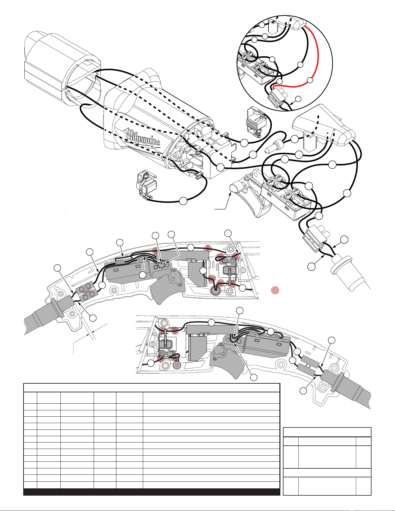
= WIRE TRAPS
or GUIDES
Cord jacket to extend .125”
beyond the cord clamp area.
7
11
12
6
13
5
8
9
4
3
2
1
T1
C1
8
11
12
1
2
4
3
9
10
7
11
12
6
10
13
5
8
9
4
3
2
1
PCB
Assembly
T1
C1
Trigger Switch
(Shown with lock-on feature)
Left Brush
Assembly
Right Brush
Assembly
Field
Assembly
Motor
Housing
Power
Cord
11
12
10
13
9
4
3
2
T1
C1
NOTE:
PCBA wire #10 can be routed
to the lower right switch position
or connect with white wire #4 in
terminal block T1 as shown .
AS AN AID TO REASSEMBLY,
TAKE NOTICE OF WIRE ROUTING AND
POSITION IN WIRE GUIDES AND
TRAPS WHILE DISMANTLING TOOL.
BE CAREFUL AND AVOID PINCHING
WIRES BETWEEN HANDLE HALVES
WHEN ASSEMBLING.
Qnty.
TERMINAL DESCRIPTION
Part No.Code
NOTE:
All leads must be held to ± 1/16".
All lead lengths are before stripping.
CONNECTOR DESCRIPTION
Wire Wire Origin or
No. Color Part No. Gauge Length Terminals, Connectors and End Wire Preparation
1 Black 22-64-3425 -- -- Component of Cord Set. Connect to T1 as shown.
2 White 22-64-3425 -- -- Component of Cord Set. Connect to T1 as shown.
3 Black 23-94-0345 -- --
Comp. of Leadwire Assembly Kit. Connect to Switch and T1 as shown.
4 White 23-94-0345 -- --
Comp. of Leadwire Assembly Kit. Connect to Switch and T1 as shown.
5 Black 18-07-0285 -- -- Comp. of Field. Connect to Left Brush Assy. as shown.
6 Black 18-07-0285 -- -- Comp. of Field. Connect to Right Brush Assy. as shown.
7 Black 18-07-0285 -- -- Comp. of Field. Connect to Wire #13 with C1 as shown.
8 Black 18-07-0285 -- -- Component of Field. Connect to Switch as shown.
9 White 22-09-1825 -- -- Comp. of PCB Assembly. Connect to Switch as shown.
10 White 22-09-1825 -- -- Comp. of PCB Assy. Connect to Switch or T1 as shown.
11 Black 22-09-1825 -- -- Comp. of PCB Assembly. Connect to Switch as shown.
12 Blue 22-09-1825 -- -- Comp. of PCB Assembly. Connect to Switch as shown.
13 Red 22-09-1825 -- -- Comp. of PCB Assembly. Connect to Wire #7 with C1.
BULK LEAD WIRE - BULLETIN 58-01-0003
WIRING SPECIFICATIONS
T1 22-56-0475 1
C1 22-56-0150 1