
49
48
3g
3d
3e
47
6
46
40b
41
42
43
40a
45c
45a
45d
45b
3a
3b
1 (4x)
3c
2
5a
13
23a
52
25
23b 27 (2x) 1 (2x)
34
35
28
32
31
33
38
37
36
39 30
40a
40b
40
45a 45b
45c 45d
45
41 42
43
51
1 23a
23b 27
23
3f
5b
5c
4
5d
6
7
5a 5b 5c
5d 5e
5
22
26
44
3a 3b 3c 3d
3e 3f 3g
3
6 46
47
56
5e
15
16
17
18
19
21
15 16
17 18
50
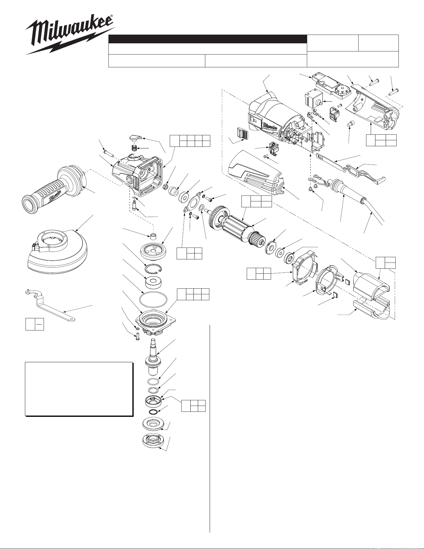
*LUBRICATION NOTE:
When servicing the Gears (5a & 48)
or the Gearcase (3c), 90-95% of the
old grease must be removed prior
to new grease being added.
FIG. LUBRICATION*
5a,48 Type "Y" Grease, No. 49-08-5270,
Must Be Applied To All Gear Teeth.
EXAMPLE:
Component Parts (Small #)
Are Included When Ordering
The Assembly (Large #).
0
00
FIG. PART NO. DESCRIPTION OF PART NO. REQ.
26 22-64-3430 Power Cord (1)
27 05-88-1300 M4 x 28mm Pan Hd. ST Screw T-20 (2)
28 22-56-0150 Close End Connector (1)
30 22-09-1840 PCB Assembly (1)
31 23-74-1620 Terminal (1)
32 23-74-1615 Terminal (1)
33 23-66-2665 On-Off Switch (1)
34 31-84-0090 Slide Pole - Back (1)
35 31-84-0095 Slide Pole - Front (1)
36 05-88-0030 M3 x 8.5mm Pan Hd. ST Screw T-10 (2)
37 22-18-2250 Carbon Brush Assembly (Set of 2) (1)
38 31-89-0245 Slide Switch Button (1)
39 31-50-2130 Motor Housing (1)
40 18-07-0295 Field Assembly (1)
40a --------------- Field Halve (1)
40b --------------- Field Halve (1)
41 42-28-0085 Rubber Block (2)
42 --------------- Baffl e Foot (1)
43 --------------- Baffl e (1)
44 42-96-0016 Rubber Bearing Cap (1)
45 16-10-0845 Armature Assembly (1)
45a 02-04-2110 Ball Bearing (1)
45b --------------- Armature (1)
45c 45-88-0406 Washer (1)
45d --------------- Magnetic Disc (1)
46 05-88-1280 M4 x 10mm Pan Hd. Mach. Screw T-20 (2)
47 44-86-0155 Bearing Retainer (1)
48 32-60-0310 Pinion (1)
49 05-55-0620 M5 Hex Nut (1)
50 14-46-6105 Flange with Ramps Assembly (1)
51 42-14-0515 Baffl e Assembly (1)
52 05-78-0305 M3.5 x 7mm Pan Hd. Phil. Switch Scr. (2)
56 44-86-0145 Bearing Retaining Plate Assembly (1)
12-20-1560 Service Nameplate (Not Shown) (1)
10-20-2225 Bi-Lingual Warning Label (Not Shown) (1)
FIG. PART NO. DESCRIPTION OF PART NO. REQ.
1 05-88-1650 M4 x 25mm Pan Hd. ST Screw T-20 (6)
2 42-62-0125 Side Handle Assembly (1)
3 14-30-1155 Gearcase Assembly (1)
3a --------------- Spindle Lock Button (1)
3b --------------- Spindle Lock Spring (1)
3c --------------- Gearcase (1)
3d --------------- O-Ring (1)
3e --------------- Spindle Lock Pin (1)
3f --------------- Needle Bearing (1)
3g 02-04-0620 Ball Bearing (1)
4 34-40-0560 O-Ring (1)
5 14-73-0425 Spindle Hub Assembly (1)
5a --------------- Spiral Bevel Gear (1)
5b --------------- Retaining Ring (1)
5c --------------- Ball Bearing (1)
5d --------------- Spindle Hub (1)
5e --------------- 5/8" Spindle (1)
6 05-90-0225 Spring Washer (6)
7 05-88-1210 M4 x 14mm Pan Hd. Mach. Screw T-20 (4)
13 14-32-0215 5" Type 27 Guard Assembly (Shown) (1)
13 43-54-0925 5" Type 1 Guard Assy. (Not Shown) (1)
15 --------------- O-Ring (1)
16 --------------- Wavey Spring (1)
17 --------------- Flange with Ramps (1)
18 --------------- Retaining Ring (1)
19 43-34-0935 Inner Disc Flange (1)
21 44-40-0035 Outer Flange Nut (1)
22 49-96-7205 Spanner Wrench (1)
23 14-34-6125 Rear Handle Set (1)
23a --------------- Left Handle Halve (1)
23b --------------- Right Handle Halve (1)
25 44-76-0095 Cord Protector (1)
MILWAUKEE ELECTRIC TOOL CORPORATION
13135 W. Lisbon Road, Brookfi eld, WI 53005
Drwg. 4
6117-33D
54-38-2140
C95A
5" HP ANGLE GRINDER with SLIDE SWITCH & Speed Dial
REVISED BULLETIN
DATE
Mar. 2012
SERVICE PARTS LIST
BULLETIN NO.
WIRING INSTRUCTION
CAT. NO.
SPECIFY CATALOG NO. AND SERIAL NO. WHEN ORDERING PARTS
STARTING
SERIAL NUMBER
See Reverse Side
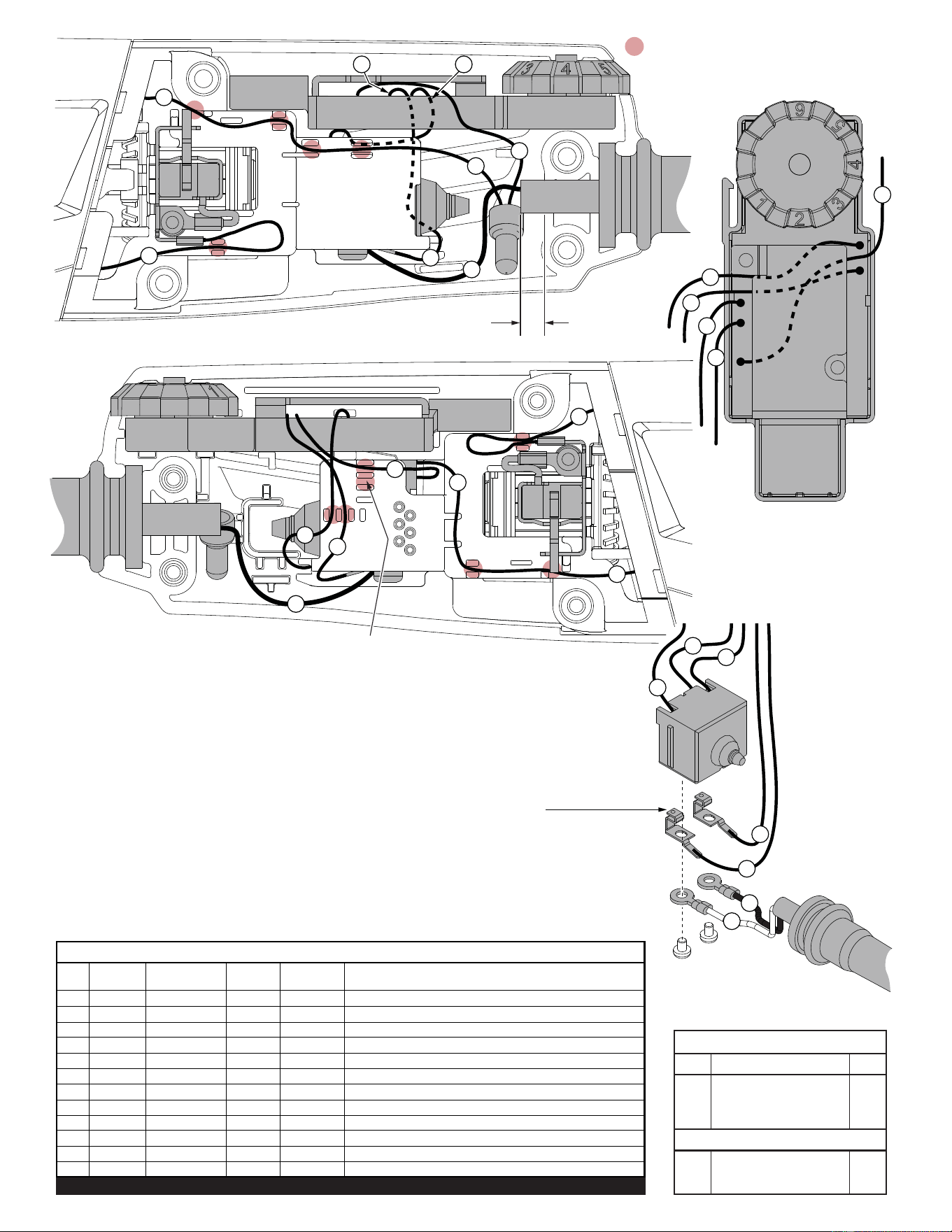
= WIRE TRAPS
or GUIDES
5
6
4
3
1
2
NOTE:
Install the two terminals
onto switch and slide the
switch down into the motor
housing prior to installing
cord wires 1 and 2 and
PCBA wires 3 and 6 from
under motor housing.
9
Place wire #6 in this trap.
See view above for wire routing.
Cord jacket is to extend .25”
beyond the clamping area.
TOP VIEW OF THE
PCB ASSEMBLY
5
7
6
3
4
9
4
1
10
3
2
10
11
7
6
4
4
9
5
8
AS AN AID TO REASSEMBLY, TAKE NOTICE OF
WIRE ROUTING AND POSITION IN WIRE GUIDES
AND TRAPS WHILE DISMANTLING TOOL.
BE CAREFUL AND AVOID PINCHING WIRES
BETWEEN HANDLE HALVES WHEN ASSEMBLING.
Wire Wire Origin or
No. Color Part No. Gauge Length Terminals, Connectors and End Wire Preparation
1 Black 22-64-3430 -- -- Component of Cord Set. Connect to Switch.
2 White 22-64-3430 -- -- Component of Cord Set. Connect to Switch.
3 Black 22-09-1840 -- -- Component of PCBA. Connect to Switch.
4 White 22-09-1840 -- -- Component of PCBA. Connect to Switch.
5 Black 22-09-1840 -- -- Component of PCBA. Connect to Switch.
6 White 22-09-1840 -- -- Component of PCBA. Connect to Switch.
7 Red 22-09-1840 -- -- Component of PCBA. Connect to C1 with wire #10.
8 White 18-07-0295 -- -- Component of Field. Connect to Right Brush Assy.
9 White 18-07-0295 -- -- Component of Field. Connect to Switch.
10 White 18-07-0295 -- -- Component of Field. Connect to C1 with wire #7.
11 White 18-07-0295 -- -- Component of Field. Connect to Left Brush Assy.
BULK LEAD WIRE - BULLETIN 58-01-0003
WIRING SPECIFICATIONS
Qnty.
TERMINAL DESCRIPTION
Part No.Code
NOTE:
All leads must be held to ± 1/16".
All lead lengths are before strip-
CONNECTOR DESCRIPTION
C1 22-56-0150 1
C1