
47
6
46
40b
41
42
43
40a
45c
44
45a
45d
45b
23a
38
36
40a
40b
40
45a 45b
45c 45d
45
41 42
43
52
2723b
37
54
31
53
39
35
32
26
25
23a 23b
27
23
6 46
47
56
30
29
28
57
34
33
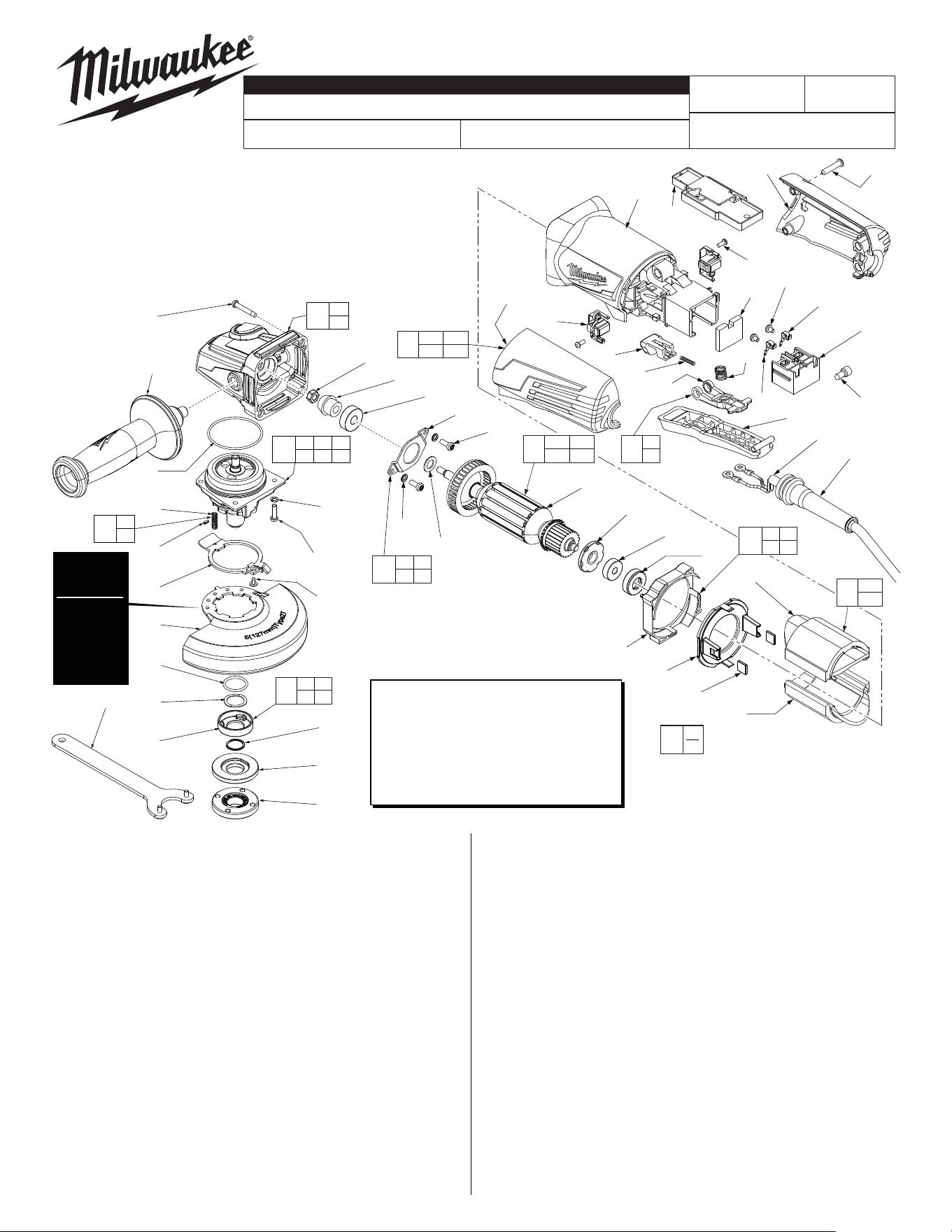
EXAMPLE:
Component Parts (Small #)
Are Included When Ordering
The Assembly (Large #).
0
00
33
34
60
49
48
3g
15 16
17 18
50
5b
5c
65
3
1
(4x)
2
4
5c
5b
5d
13
15
16
17
22
6
(4x)
7(4x)
5e
18
19
21
4 5b 5c
5d 5e 48
5
3g
Type 27
Guard is
Std. Equip.
Optional
Type 1
Guard
available.
Order No.
43-54-1230.
*LUBRICATION NOTE:
When servicing the Gear Case Assembly,
90-95% of the old grease must be re-
moved prior to new grease being added.
FIG. LUBRICATION*
5 Type "Y" Grease, No. 49-08-5270,
Must Be Applied To All Gear Teeth.
FIG. PART NO. DESCRIPTION OF PART NO. REQ.
1 05-88-1650 M4 x 25mm Pan Hd. ST Screw T-20 (4)
2 42-62-0125 Side Handle Assembly (1)
3 14-30-1156 Gearcase Assembly (1)
3g 02-04-0620 Ball Bearing (1)
4 34-40-0560 O-Ring (1)
5 14-73-0475 5/8"-11 Spindle Hub Kit (1)
5b --------------- Steel Pin (1)
5c --------------- Spring (1)
5d 44-20-0155 Guard Locking Tang (1)
5e 05-81-0020 M3 x 5mm Pan Hd. ST T-8 Screw (1)
FIG. PART NO. DESCRIPTION OF PART NO. REQ.
6 05-90-0225 Spring Washer (6)
7 05-78-5316 M4 x 14mm Pan Hd. Tapt. Screw T-20 (4)
13 43-54-1220 5" Type 27 Guard (Standard Equip.) (1)
13 43-54-1230 5" Type 1 Guard (Optional, Not Shown) (1)
15 --------------- O-Ring (1)
16 --------------- Wavey Spring (1)
17 --------------- Flange with Ramps (1)
18 --------------- Retaining Ring (1)
19 43-34-0935 Inner Disc Flange (1)
21 44-40-0035 Outer Flange Nut (1)
22 49-96-7215 Spanner Wrench (1)
23 31-44-0645 Rear Handle Set (1)
23a --------------- Left Handle Halve (1)
23b --------------- Right Handle Halve (1)
25 44-76-0095 Cord Protector (1)
26 22-64-3430 Power Cord (1)
27 05-88-1300 M4 x 28mm Pan Hd. ST Screw T-20 (4)
28 22-09-1865 PCB Assembly (1)
29 23-74-1620 Terminal (1)
30 23-74-1615 Terminal (1)
31 23-66-2665 On-OSwitch (1)
32 31-92-0285 Paddle Trigger (1)
33 --------------- Paddle Trigger Spring (1)
34 --------------- Paddle Linkage (1)
35 40-50-1155 Lock Button Spring (1)
36 42-42-0495 Lock-On Button (1)
37 05-88-0030 M3 x 8.5mm Pan Hd. ST Screw T-10 (2)
38 22-18-2250 Carbon Brush Assembly (Set of 2) (1)
39 31-50-2165 Motor Housing (1)
40 18-07-0300 Field Assembly (1)
FIG. PART NO. DESCRIPTION OF PART NO. REQ.
40a --------------- Field Halve (1)
40b --------------- Field Halve (1)
41 42-28-0085 Rubber Block (2)
42 --------------- BaeFoot (1)
43 --------------- Bae (1)
44 42-96-0016 Rubber Bearing Cap (1)
45 16-10-0845 Armature Assembly (1)
45a 02-04-2110 Ball Bearing (1)
45b --------------- Armature (1)
45c 45-88-0406 Washer (1)
45d --------------- Magnetic Disc (1)
46 05-78-0105 M4 x 10mm Pan Hd. Tapt. Screw T-20 (2)
47 44-86-0155 Bearing Retainer (1)
48 --------------- Pinion (1)
49 05-55-0620 M5 Hex Nut (1)
50 14-46-6105 Flange with Ramps Assembly (1)
52 42-14-0515 BaeAssembly (1)
53 05-78-0305 M3.5 x 7mm Pan Hd. Phil. Switch Scr. (2)
54 23-16-0075 Foam Block (1)
56 44-86-0145 Bearing Retaining Plate Assembly (1)
57 22-56-0150 Closed End Wire Connector (1)
60 14-46-6100 Paddle Linkage/Spring Service Kit (1)
65 14-46-0241 Spring/Pin Kit (1)
12-20-1560 Service Nameplate (Not Shown) (1)
10-20-2225 Bi-Lingual Warning Label (Not Shown) (1)
MILWAUKEE TOOL ● www.milwaukeetool.com
13135W.LisbonRoad,Brookeld,WI53005
Drwg. 3
6117-31
54-38-2112
C92C and E
5" HP ANGLE GRINDER with PADDLE SWITCH
REVISED BULLETIN
54-38-2111
DATE
July 2023
SERVICE PARTS LIST
BULLETIN NO.
WIRING INSTRUCTION
CAT. NO.
SPECIFY CATALOG NO. AND SERIAL NO. WHEN ORDERING PARTS
STARTING
SERIAL NUMBER
See Reverse Side
«
«
«
«
«
«
«
«
«
«
«
«
«= Part number change
from previous service
parts list.
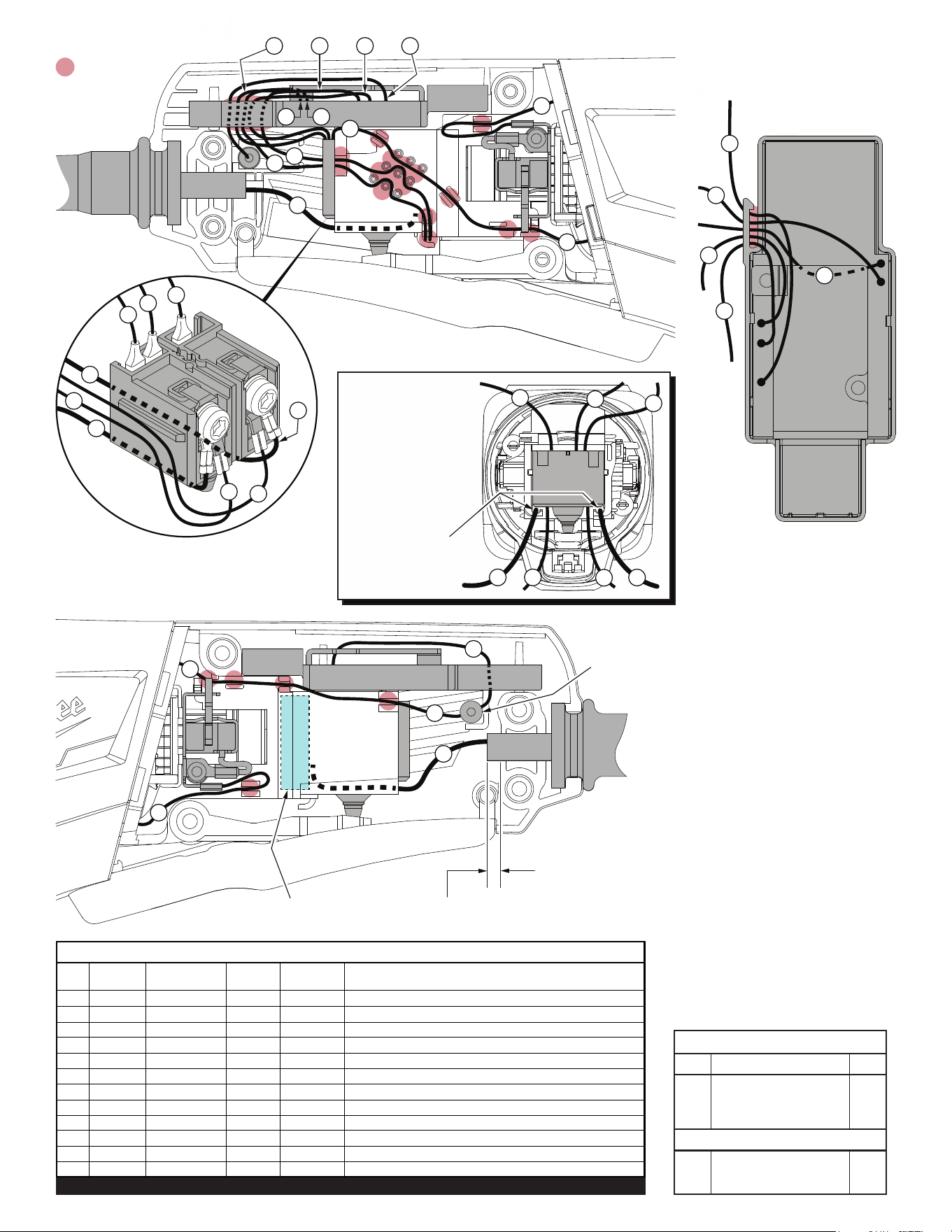
= WIRE TRAPS
or GUIDES
Foam Block
No. 23-16-0075
Attach all wires to the switch as shown prior
to inserting switch into the motor housing.
Be sure that foam block is seated in the switch
opening of motor housing before switch is
installed.
Back view of
Motor Housing
Cord wires #1 and #2
are to be routed under
switch, in the channels
of motor housing.
Wires #3 and #4 are to
be in the open area
between the channels.
Top view of
PCB Assembly
2
2
4
1
3
5
3
6
8
Channels
for cord wires.
5
4
6
7
9
8
5
6
7
1
3
4
Cord jacket is to extend approx. .25”
beyond the clamping area of the tool.
11
2
2
4
1
3
5
6
8
3
8
4
3
5
7
C1
Closed End
Wire Connector
10
10
AS AN AID TO REASSEMBLY,
TAKE NOTICE OF WIRE ROUTING AND
POSITION IN WIRE GUIDES AND TRAPS
WHILE DISMANTLING TOOL.
BE CAREFUL AND AVOID PINCHING
WIRES BETWEEN HANDLE HALVES
WHEN ASSEMBLING.
Wire Wire Origin or
No. Color Part No. Gauge Length Terminals, Connectors and End Wire Preparation
1 Black 22-64-3430 -- -- Component of Cord Set. Connect to Switch.
2 White 22-64-3430 -- -- Component of Cord Set. Connect to Switch.
3 Black 22-09-1865 -- -- Component of PCBA. Connect to Switch.
4 White 22-09-1865 -- -- Component of PCBA. Connect to Switch.
5 Black 22-09-1865 -- -- Component of PCBA. Connect to Switch.
6 White 22-09-1865 -- -- Component of PCBA. Connect to Switch.
7 Red 22-09-1865 -- -- Component of PCBA. Connect to C1 with wire #10.
8 Black 18-07-0300 -- -- Component of Field. Connect to Switch.
9 Black 18-07-0300 -- -- Component of Field. Connect to Right Brush Assy.
10 Black 18-07-0300 -- -- Component of Field. Connect to C1 with wire #7.
11 Black 18-07-0300 -- -- Component of Field. Connect to Left Brush Assy.
BULK LEAD WIRE - BULLETIN 58-01-0003
WIRING SPECIFICATIONS
Qnty.
TERMINAL DESCRIPTION
Part No.Code
NOTE:
All leads must be held to ± 1/16".
All lead lengths are before stripping.
CONNECTOR DESCRIPTION
C1 22-56-0150 1