
Technical Support and E-Warranty Certificate www.vevor.com/support
Food Warmer Display
Model:SC-CJ-60S/SC-CJ-601/
SC-CJ-602/SC-CJ-603
We continue to be committed to provide you tools with competitive price.
"Save Half", "Half Price" or any other similar expressions used by us only represents an
estimate of savings you might benefit from buying certain tools with us compared to the major
top brands and does not necessarily mean to cover all categories of tools offered by us. You
are kindly reminded to verify carefully when you are placing an order with us if you are
actually saving half in comparison with the top major brands.

- 1 -
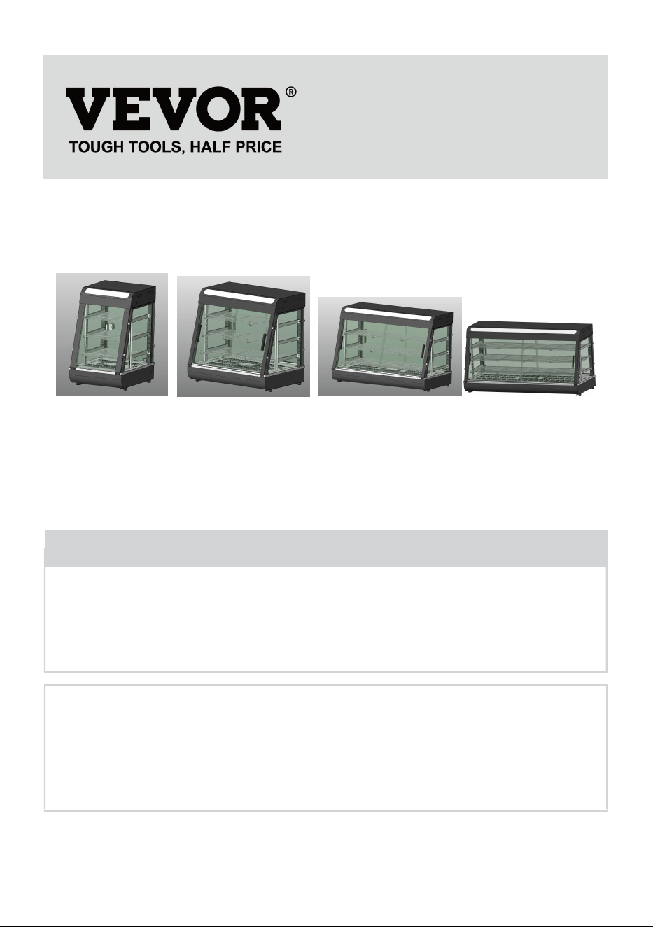
MODEL:SC-CJ-60S/SC-CJ-601/SC-CJ-602/SC-CJ-603
SC-CJ60S SC-CJ-601 SC-CJ-602 SC-CJ-603
Have product questions? Need technical support? Please feel free to
contact us:
Technical Support and E-Warranty Certificate
www.vevor.com/support
NEED HELP? CONTACT US!
This is the original instruction, please read all manual instructions
carefully before operating. VEVOR reserves a clear interpretation of our
user manual. The appearance of the product shall be subject to the
product you received. Please forgive us that we won't inform you again if
there are any technology or software updates on our product.
Food Warmer Display
- 2 -
Warning-To reduce the risk of injury, user must read
instructions manual carefully.
CORRECT DISPOSAL
This product is subject to the provision of European Directive
2012/19/EU. The symbol showing a wheelie bin crossed
through indicates that the product requires separate refuse
collection in the European Union. This applies to the product
and all accessories marked with this symbol. Products marked
as such may not be discarded with normal domestic waste, but
must be taken to a collection point for recycling electrical and
electronic devices.
Indoor Use Only
Warm reminder
To ensure that this product will not be scratched during transportation, a
protective film is attached to the surface of the machine. Please tear off all
protective films before use!
1. Instructions for use:
1. The product must be safely grounded before use!
2. The voltage used by the product must be consistent with the rated
voltage.
3. During each use, add water to the water basin to 2/3 of the capacity
before turning on the power.
4. Turn on the power, the power indicator light is on, turn the temperature
control heating switch, and select the insulation temperature of the food to
increase the temperature of the space inside the cabinet. Through natural
convection, the temperature of each layer can be kept consistent.

- 3 -
5. During use, if you need lighting, you can turn on the lighting switch of the
light group, and all lights will be turned on, which can improve the display
effect.
6. After use, the power must be cut off when cleaning to prevent accidents;
7. If any abnormality occurs during use, stop using it and ask a
professional to troubleshoot it before continuing to use it.
This product is not intended for use by persons (including children) with
reduced physical, sensory, or mental capabilities or lack of experience and
knowledge.
9. Since the temperature of the equipment is relatively high during
operation, do not bring your hands or other parts of the body close to the
surface of the machine to avoid burns or other injuries.
2. Precautions and maintenance:
1. It should be operated by designated personnel and should be proficient
in the use of machinery and equipment.
2. Be careful when moving the machine. If there is a fault, it must be
repaired by a professional. Do not knock it.
3. Please do not install and store this equipment in the following locations
to avoid malfunction due to misoperation:
3.1 On an unstable table or counter.
3.2 Places where the temperature is too high or too low.
3.3 Places with excessive air volume and excessive dust.
3.4 Places where the power supply voltage is very unstable.
3.5 Where there is no good grounding device.
4. The appliance must not be cleaned with a water spray pipe or immersed
in water to prevent electrical leakage.
5. It is strictly prohibited to use liquids that are soluble in baking paint to
wipe the surface of the insulation cabinet.
6. Special precautions:
6.1 This product is a commercial device and is not suitable for home use
6.2 It cannot be disassembled or modified. Disassembling it without
permission may cause serious accidents.

- 4 -
6.3 The power needs to be cut off before cleaning to prevent accidental
leakage accidents.
6.4 It is prohibited to use hard or sharp objects to scratch the glass.
3. Normal working environment conditions:
1. The ambient temperature is 5-50℃, and the relative air humidity is not
more than 90%;
2. Power supply voltage: 110V±10%, frequency: 60±1%HZ. (220V±10%,
frequency: 50±1%)
4. Product introduction:
1. This product has a novel and unique design, arc shape, multi-layer
adjustable grid shelf, four-sided glass perspective, the top uses an
environmentally friendly high-transparency PC board as a light-transmitting
light panel, and a white LED tube is used internally to increase the service
life; users can Put different advertising cards according to your own
preferences to increase the beauty. The convenient disassembly and
assembly structure is easy to operate, sturdy and durable, and easy to
maintain. It has an optional constant temperature and a temperature
display. The top warm tube downlight design can make the light more
uniform, and it is equipped with moisturizing compensation to keep the
food fresh. It is a special equipment for food display and heat preservation.
5. Symbol description:
In this manual, symbols are used to highlight all important safety
instructions and recommendations related to the equipment. To avoid the
risk of accidents, personal injury, or property damage, follow these
instructions with special care.
- 5 -
6. Model, specifications and main technical parameters:
Model
Voltage
(V)
Power
(KW)
Frequency
(HZ)
Temperature
range
Dimension
(MM)
SC-CJ-60S
AC110-
120
1
60
86-185F
385*490*640
AC220-
240
50
30-85℃
SC-CJ-601
AC110-
120
1.2
60
86-185F
667*470*640
AC220-
240
50
30-85℃
SC-CJ-602
AC110-
120
1.5
60
86-185F
907*470*640
AC220-
240
50
30-85℃
SC-CJ-603
AC110-
120
1.5
60
86-185F
1210*470*64
0
AC220-
240
50
30-85℃
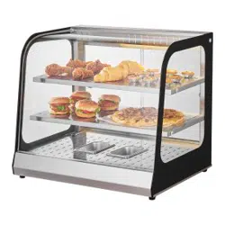
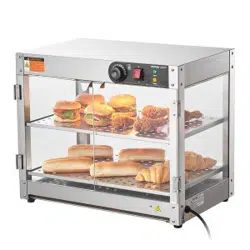
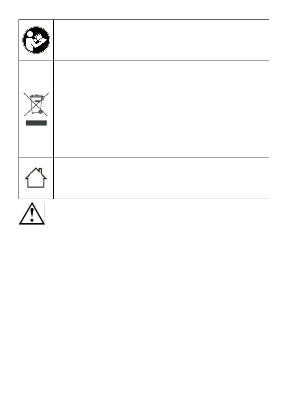
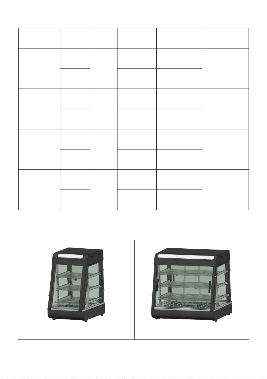
7. Product appearance picture
SC-CJ-60S
SC-CJ-601
- 6 -
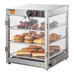
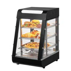
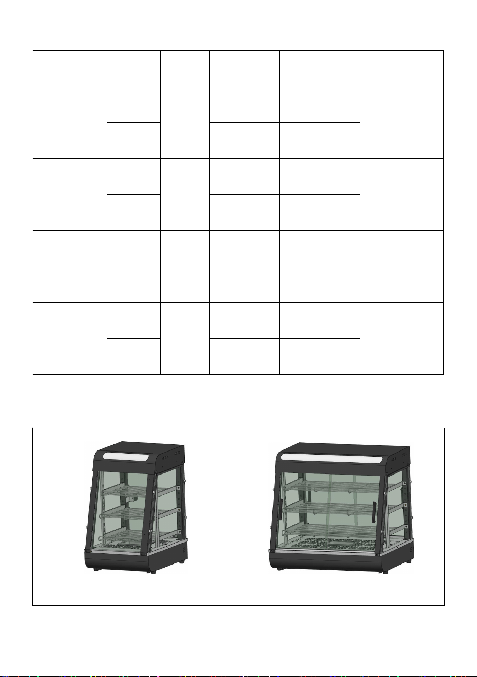
SC-CJ-602
SC-CJ603
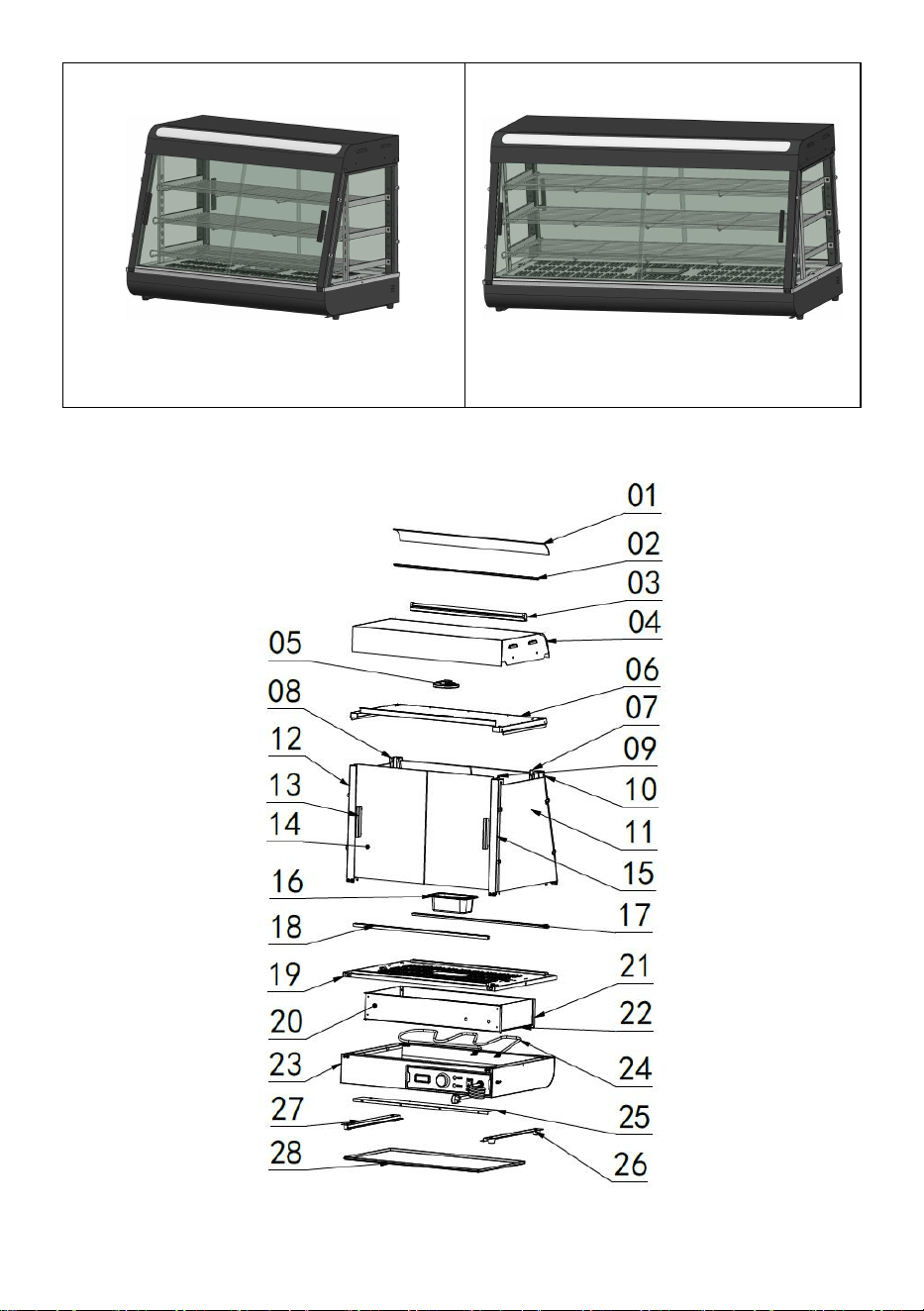
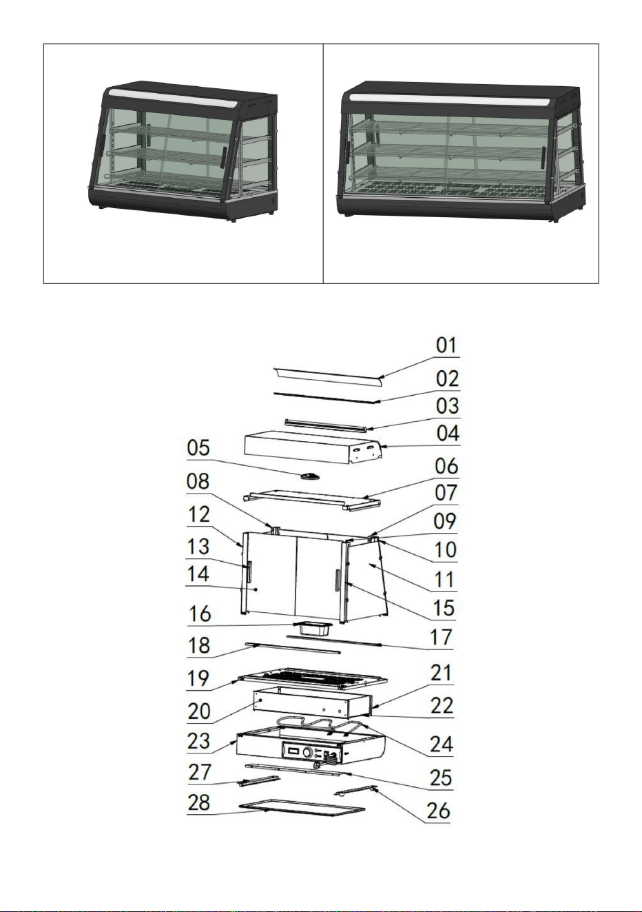
8.Product structure diagram

- 7 -
Note: The location of the electrical components is based on the design at
that time. Our company reserves the right to change the participating
designs. If the design is changed and the instructions are not updated in a
timely manner, we hope for your understanding!
Exploded chart list
No.
Name
Qty
No.
Name
Qty
01
Translucent cover
1
15
Mirror image of front
pillar
1
02
Translucent card slot
2
16
0.5L basin
1
03
LED tube 600mm
long
1
17
Glass chute inclined
opening
1
04
Top cover
1
18
Glass chute straight
mouth
1
05
Ultra-thin downlight
6W
1
19
Base table
1
06
Top cover bottom
plate
1
20
Electrical box
partition
1
07
Shelf column
2
21
Rear heat shield
1
08
Rear pillar
1
22
Side insulation panels
2
09
Aviation plug cable
1
23
Base
1
10
Rear pillar mirror
1
24
Heating pipe
1
11
Side glass
2
25
Electrical box sealing
plate
1
12
Front pillar
1
26
No.1 machine foot
4
13
Aluminum T-shaped
door handle
4
27
Slag basin guide bar
2
14
Front glass sliding
door
4
28
Slag tray
1
- 8 -
9.Product installation diagram:
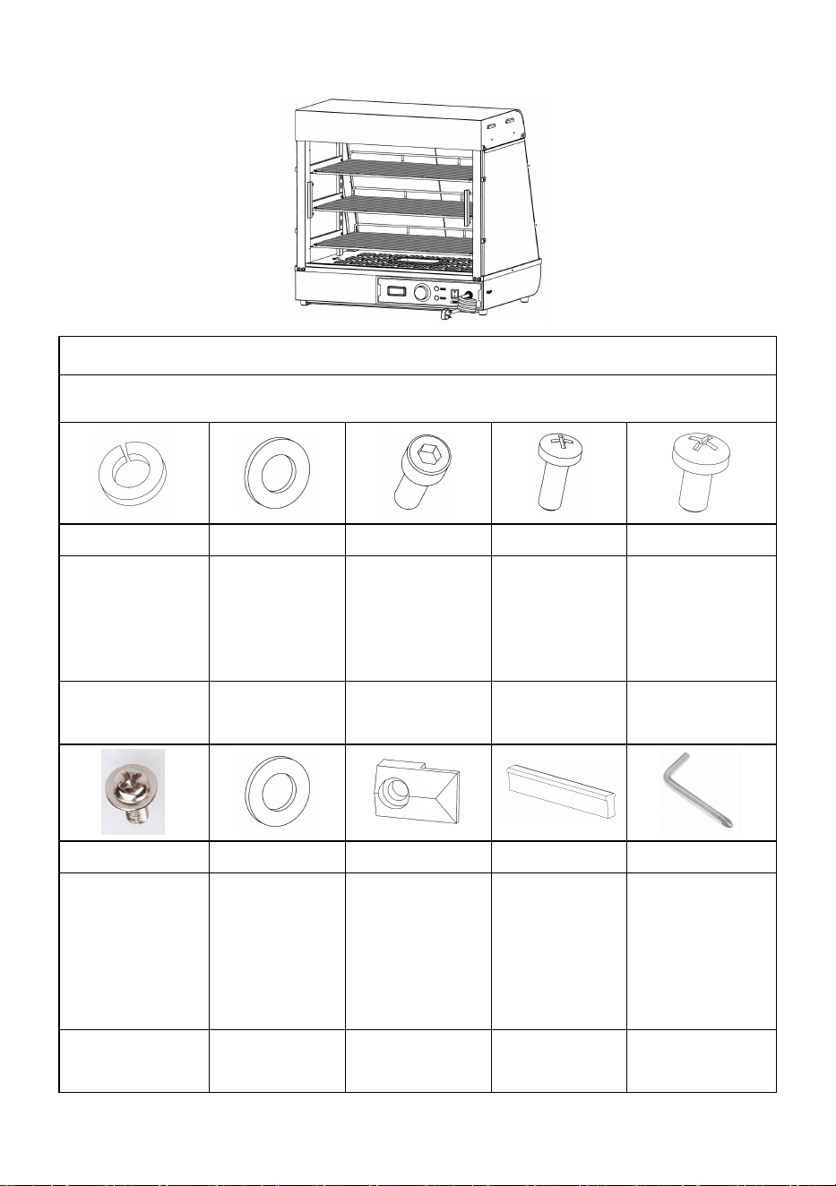
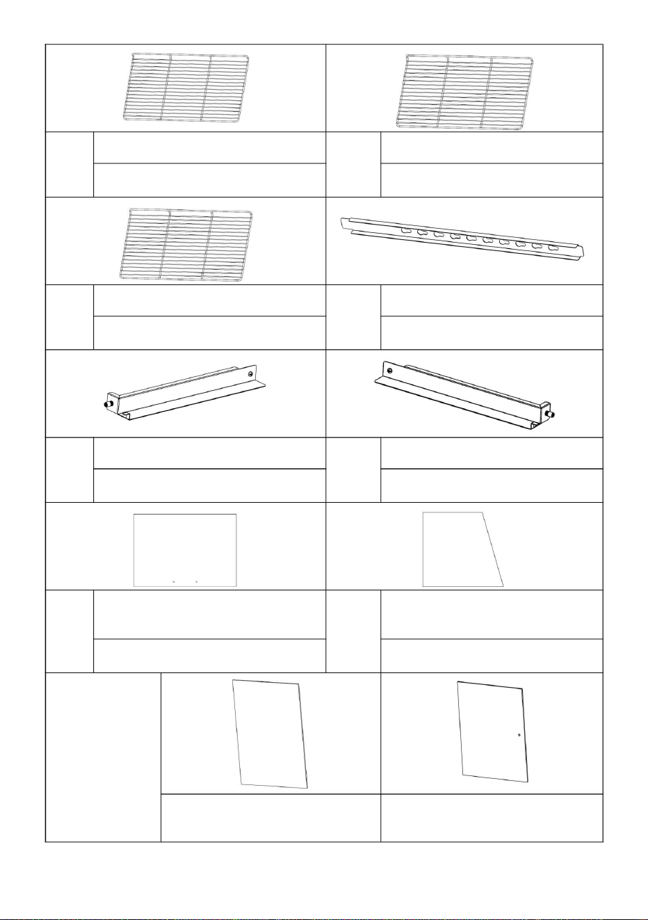
Parts kit bill of materials
Applicable to models:SC-CJ-601、SC-CJ-602、SC-CJ-603、SC-CJ-60S
A
B
C
D
E
Black spring
washer
Black flat
washer
Stainless
steel
hexagon
socket bolts
Black
round head
screws
Black round
head screws
M5
(8pcs)
M5
(8pcs)
M5X14
(4pcs)
M5X14
(8pcs)
M4X8
(8pcs)
F
G
H
I
J
Stainless
steel padded
screws
(60s none)
Silicone
gasket
(60s none)
Glass card
holder
Black
T-shaped
aluminum
handle
(60s none)
Screw tools
M4X12
(8PCS)
(16pcs)
(8pcs)
(4pcs)
(1pcs)
- 9 -
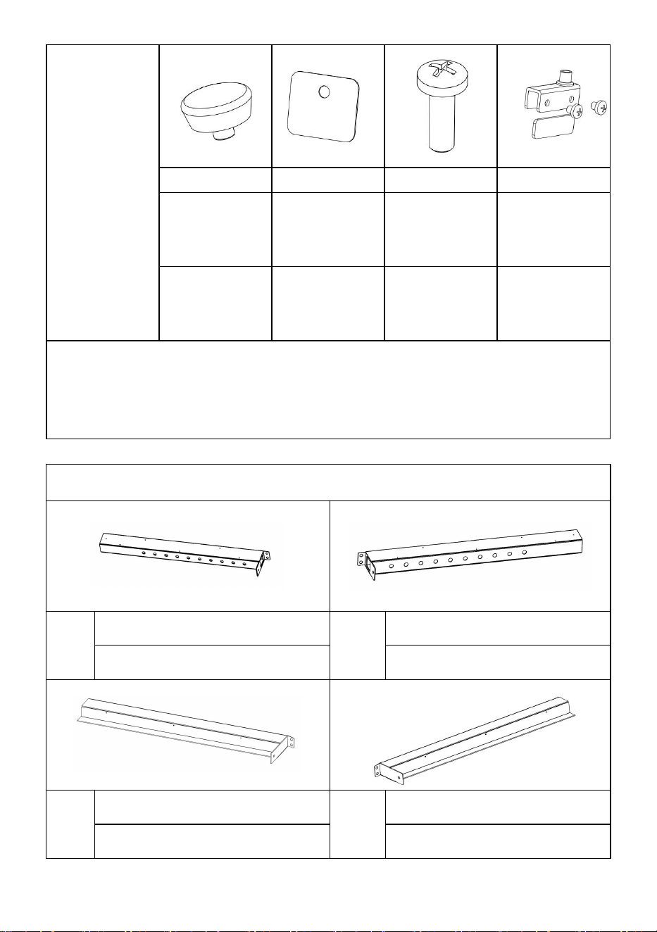
60S
Exclusive
accessory
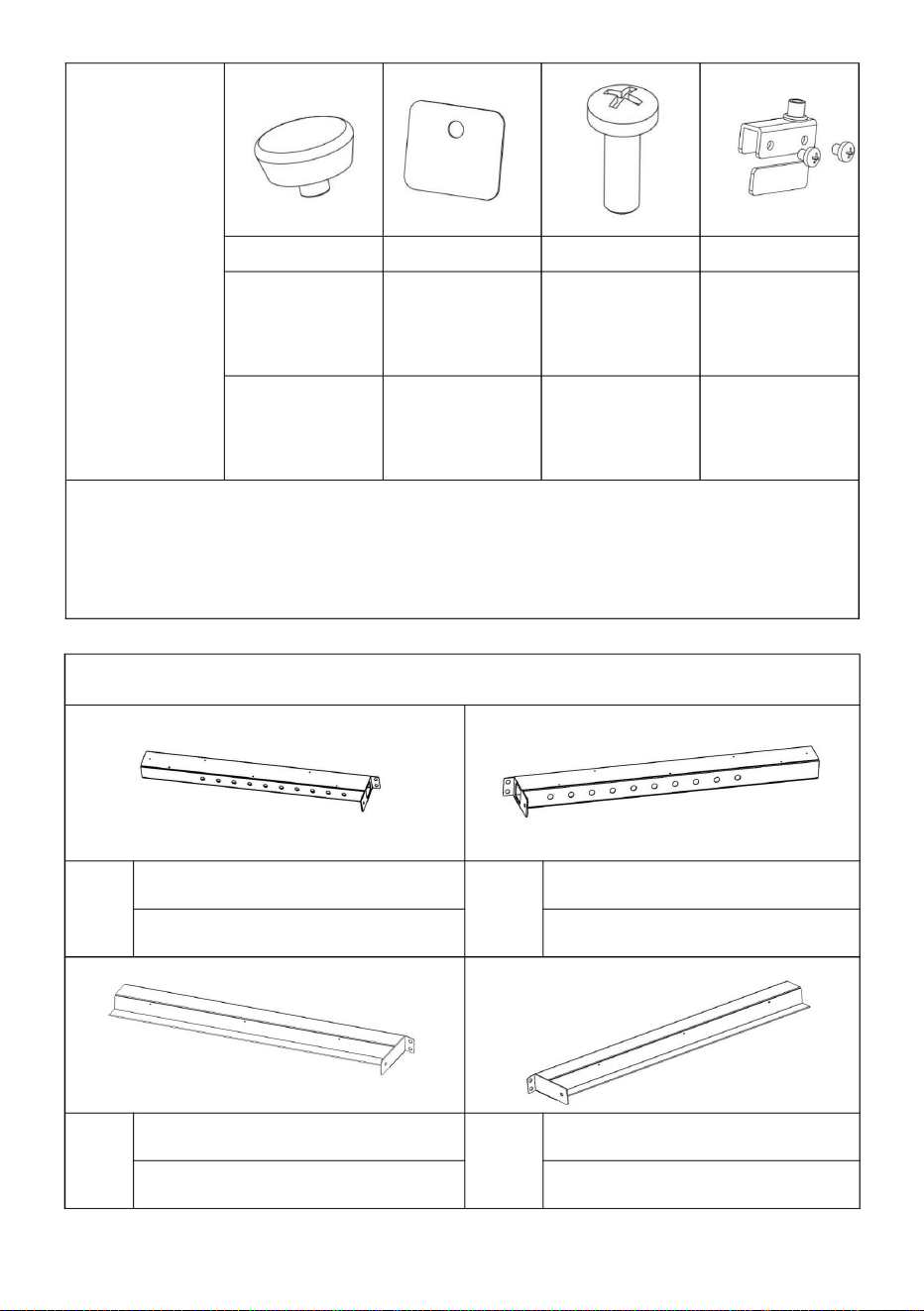
K
L
M
N
Black
Ball
Handle
Magnet
door panel
Stainless
Steel cross
screw
Glass hinge
set
(1pcs)
(1pcs)
M5X18
(1pcs)
One for
each top
and bottom
Note: The above are all the accessories in the accessory package.
During installation, you can find the screws whose codes in the picture
above match the codes printed in the screw package according to the
screws required in the installation steps for easy installation!
Assembly parts list
①
Left front pillar
②
Right front pillar
1PCS
1PCS
③
Left rear pillar
④
Right rear pillar
1PCS
1PCS
- 10 -
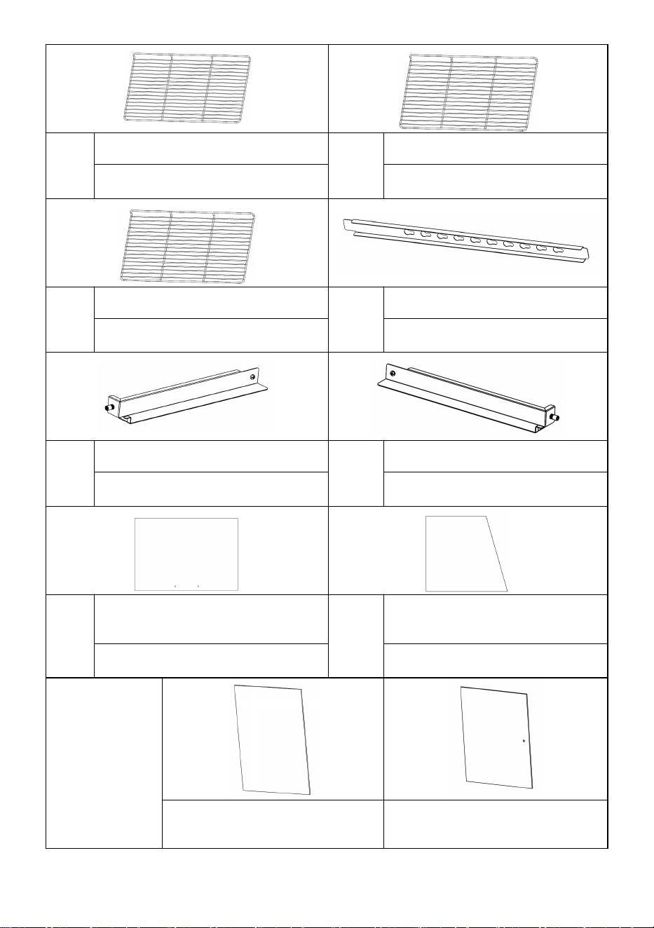
⑤
Upper shelf - shortest
⑥
Middle shelf-medium
1PCS
1PCS
⑦
Lower shelf-longest
⑧
Shelf column
1PCS
2PCS
⑨
Shelf bracket-left
⑩
Shelf bracket-right
3PCS
3PCS
⑪
Front and rear glass sliding
doors(
60
s none)
⑫
Side glass
4PCS
2PCS
60S
Exclusive
accessory
(one each)
⑬Rear glass door
⑭Front glass flip door
- 11 -
Note: The above are all accessories included in the accessory package.
Please check whether the accessories are complete before installation!
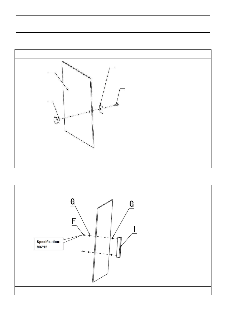
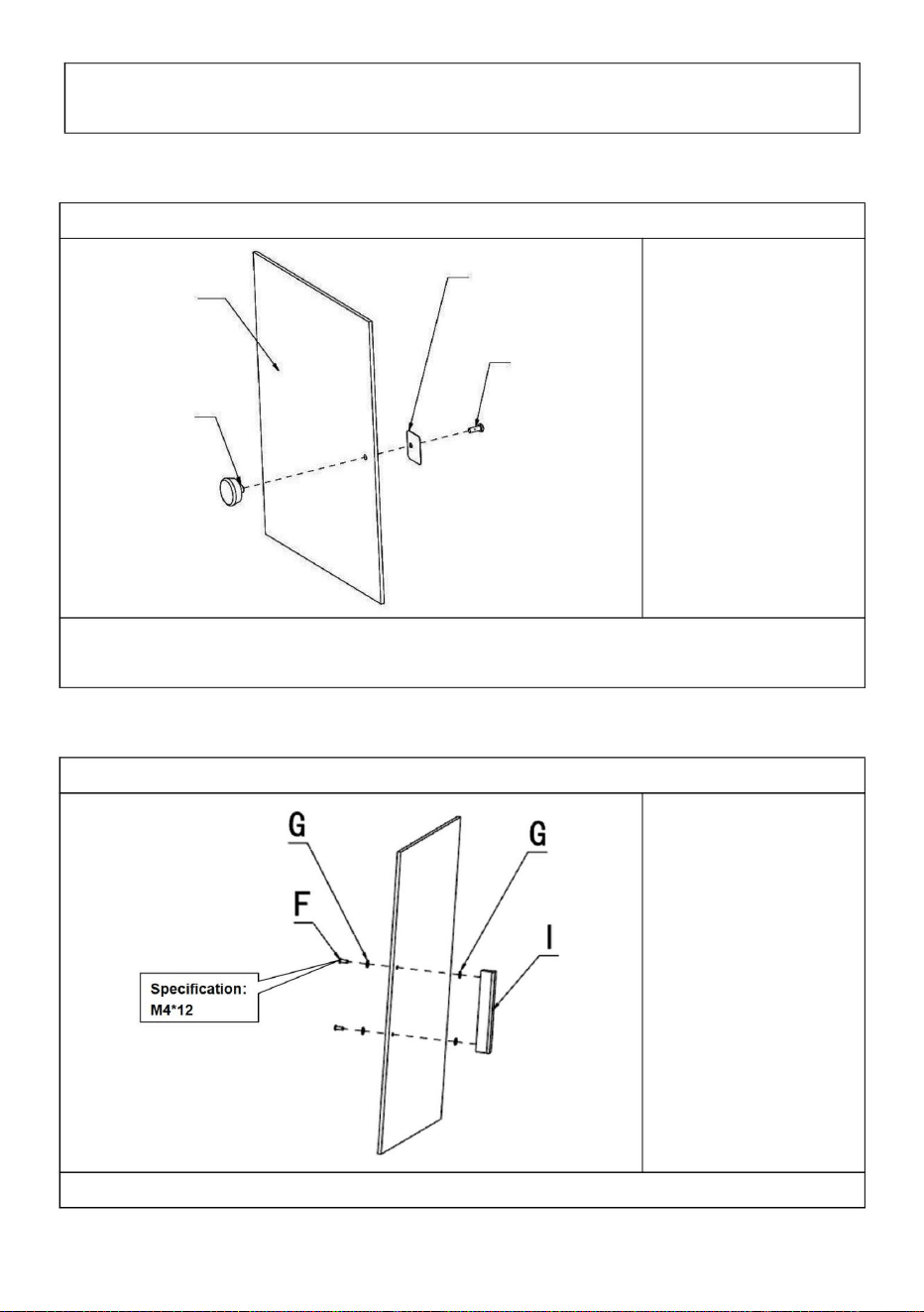
SC-CJ-60 Series Universal Installation Diagram
K (1PCS)
L (1PCS)
M (1PCS)
Step 1(60s)
SC-CJ-60 Series Universal Installation Diagram
G (4PCS)
F (2PCS)
I (1PCS)
Step 1(601 602 603)
K
L
M
⑭

- 12 -
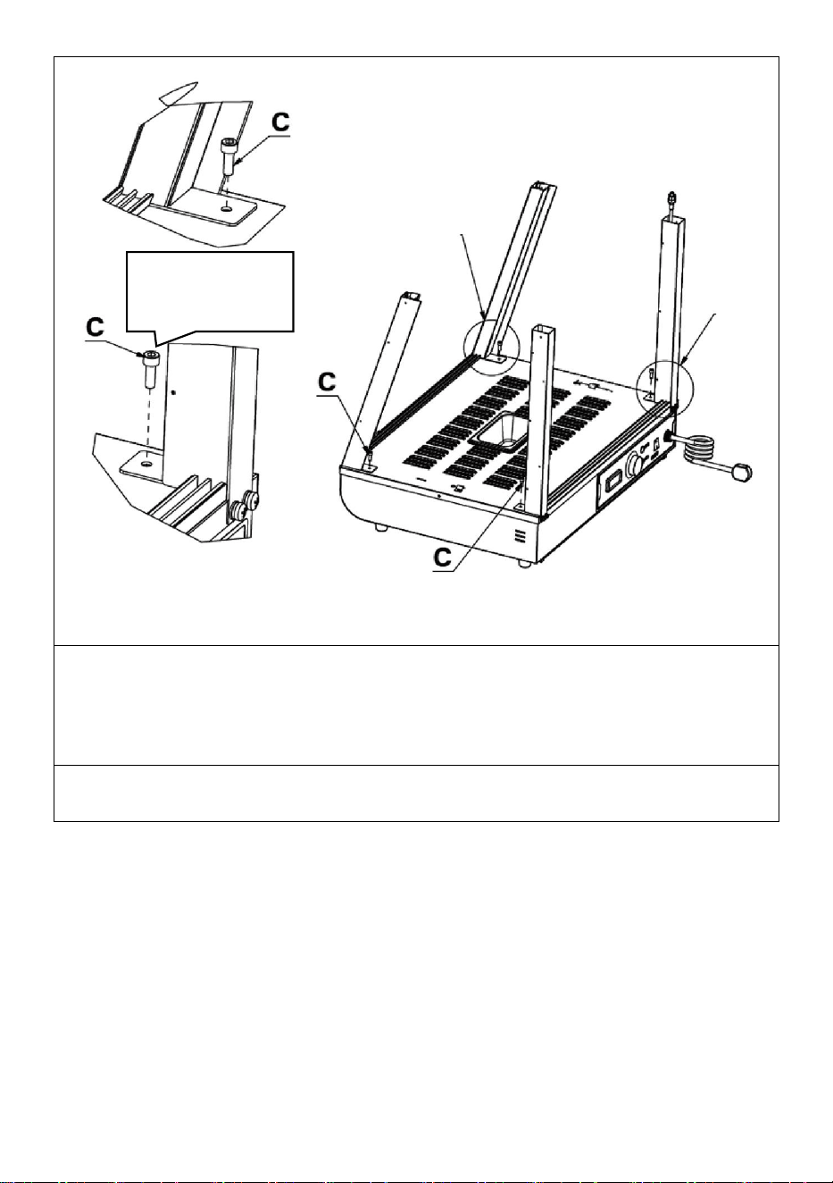
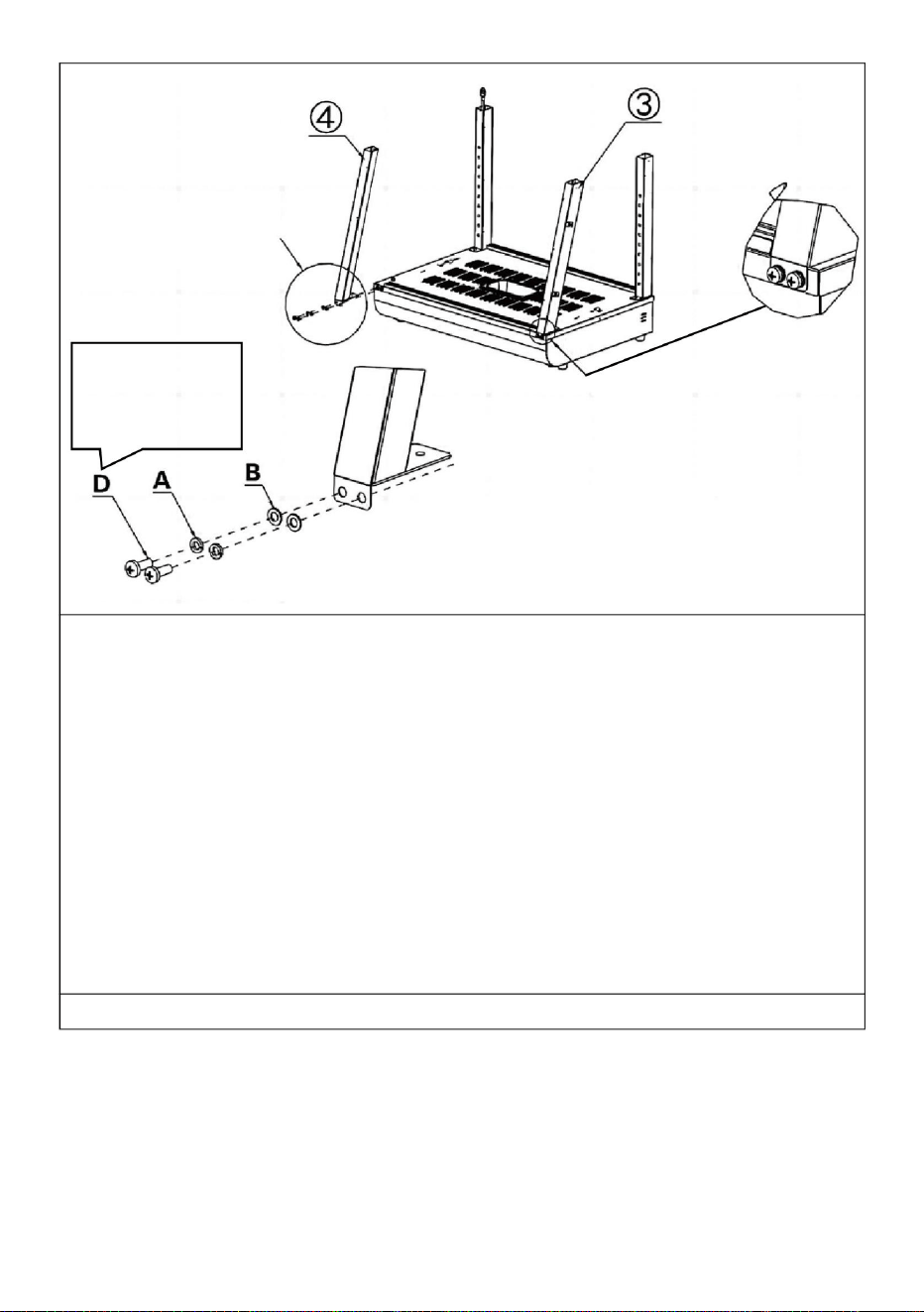
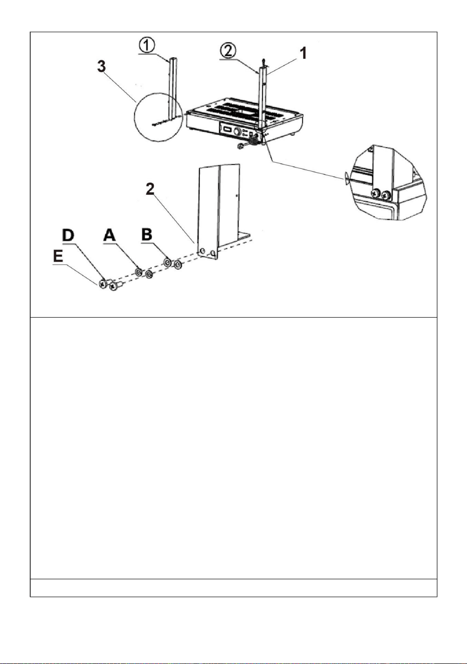
1. Pass the light cord connector protruding from the base through the
column and hang it above the column.
Note: When installing the columns on both sides, please note that the
side with holes in the column faces the outside of the machine for
installation!
2. According to the order of the picture, use the corresponding screws:
"D, A, B" to lock the accessories: "①, ②" on the reserved nut holes
respectively.
3.Detail image A
① (1PCS)
② (1PCS)
A (4PCS)
B (4PCS)
D (4PCS)
E (Specification:M5*14)
Step 2
Detail image A

- 13 -
1. According to the order of the picture, use the corresponding screws:
"D, A, B" to lock the accessories: "③, ④" on the reserved nut holes
respectively.
Note: When installing the columns on both sides, please note that the
side with holes in the column faces the outside of the machine for
installation!
③(1PCS)
④(1PCS)
A (4PCS)
B (4PCS)
D (4PCS)
Step 3
Detail image A
Specificatio
n:M5*14
Detail image A
- 14 -
1.Use screw “C” to fix the four columns to the reserved nuts on the base
in the same way as shown in the detailed picture.
C (4PCS)
Step 4
Specification:
M5*14
Detail image A
Detail
image
B
Detail image B
- 15 -
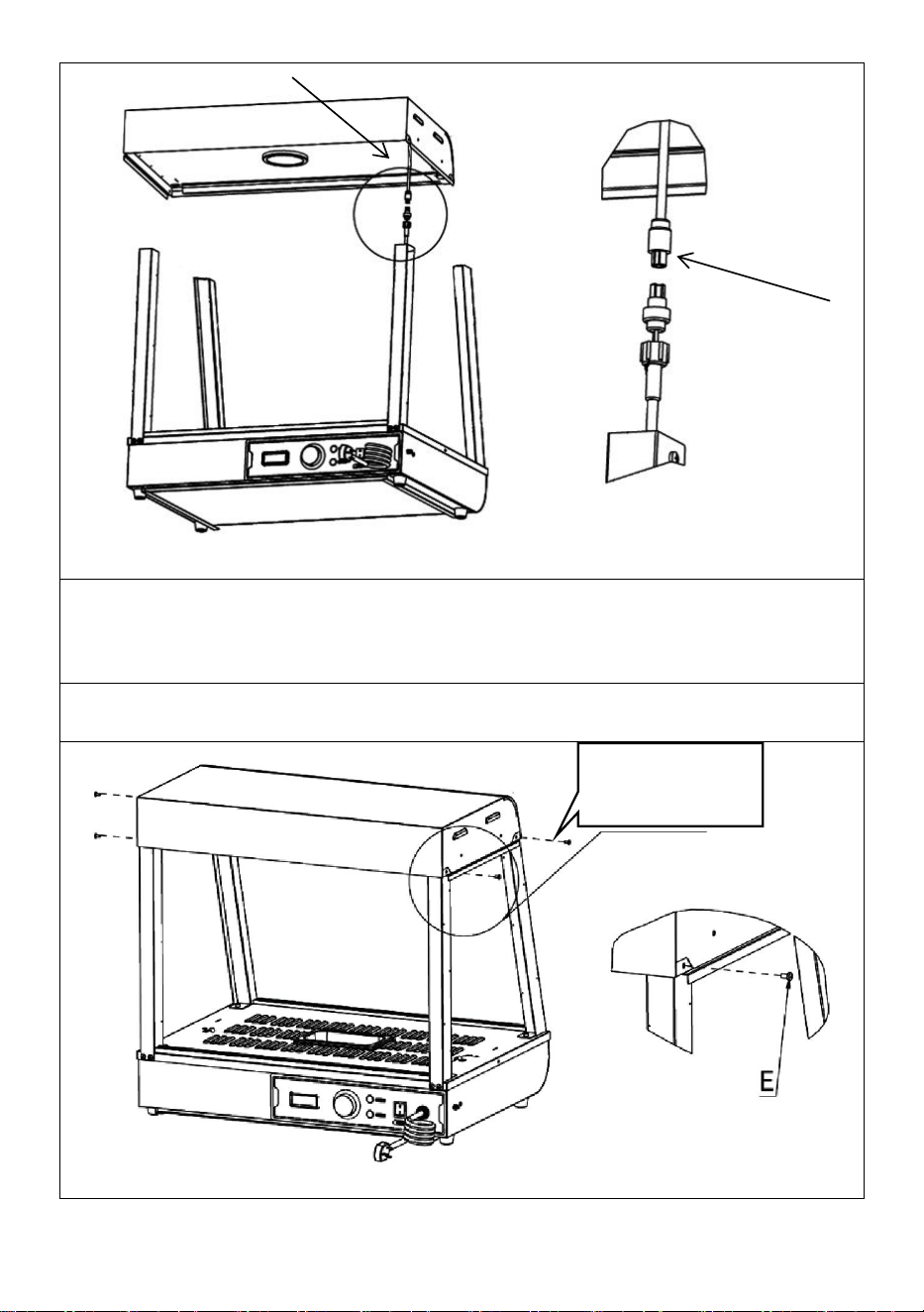
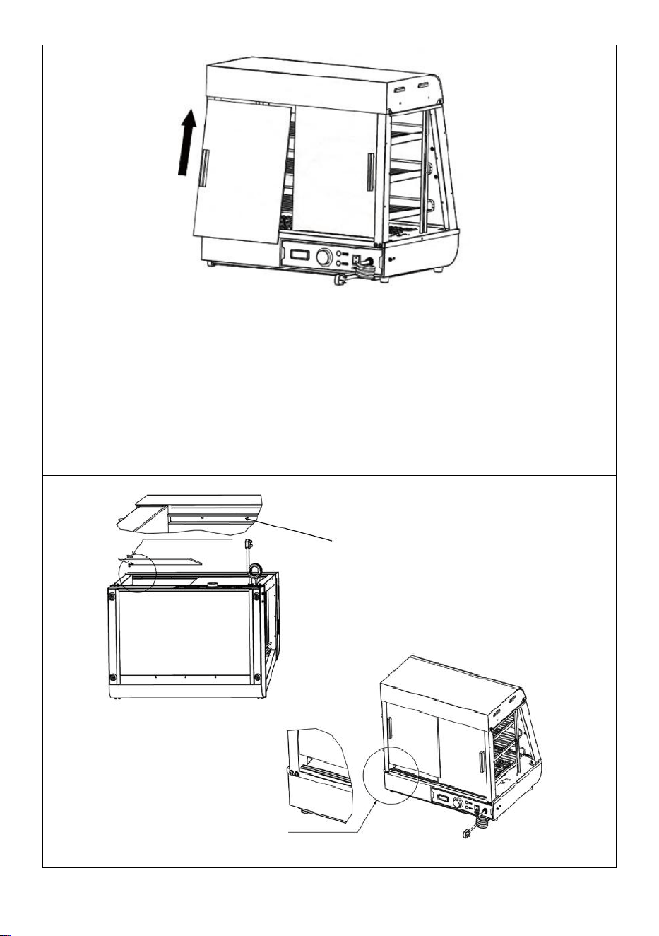
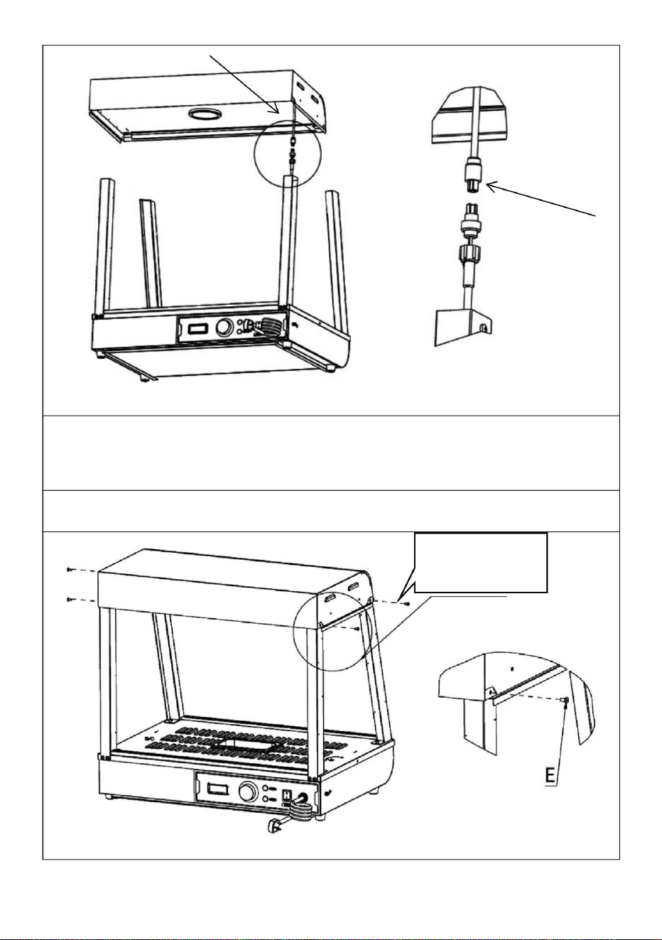
1. Connect the wire connector protruding from the top cover to the
connector hanging on the column and tighten it, then insert the
connected connector into the column and hide it.
Step 5
Detail image A
Detail image A
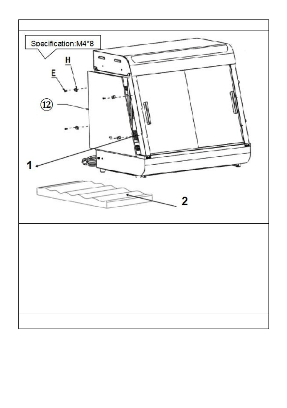
1
Specification:
M4*8
1

- 16 -
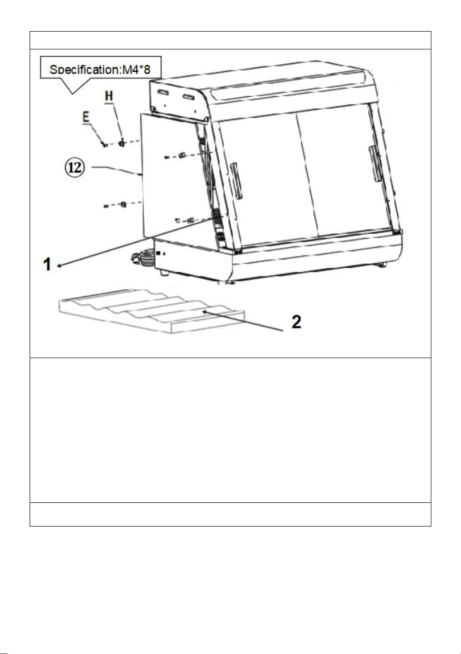
1. Place the top cover on the four upright posts, and then use "screws E"
to fix the top cover and the upright posts (four in total).
E (4PCS)
Step 6
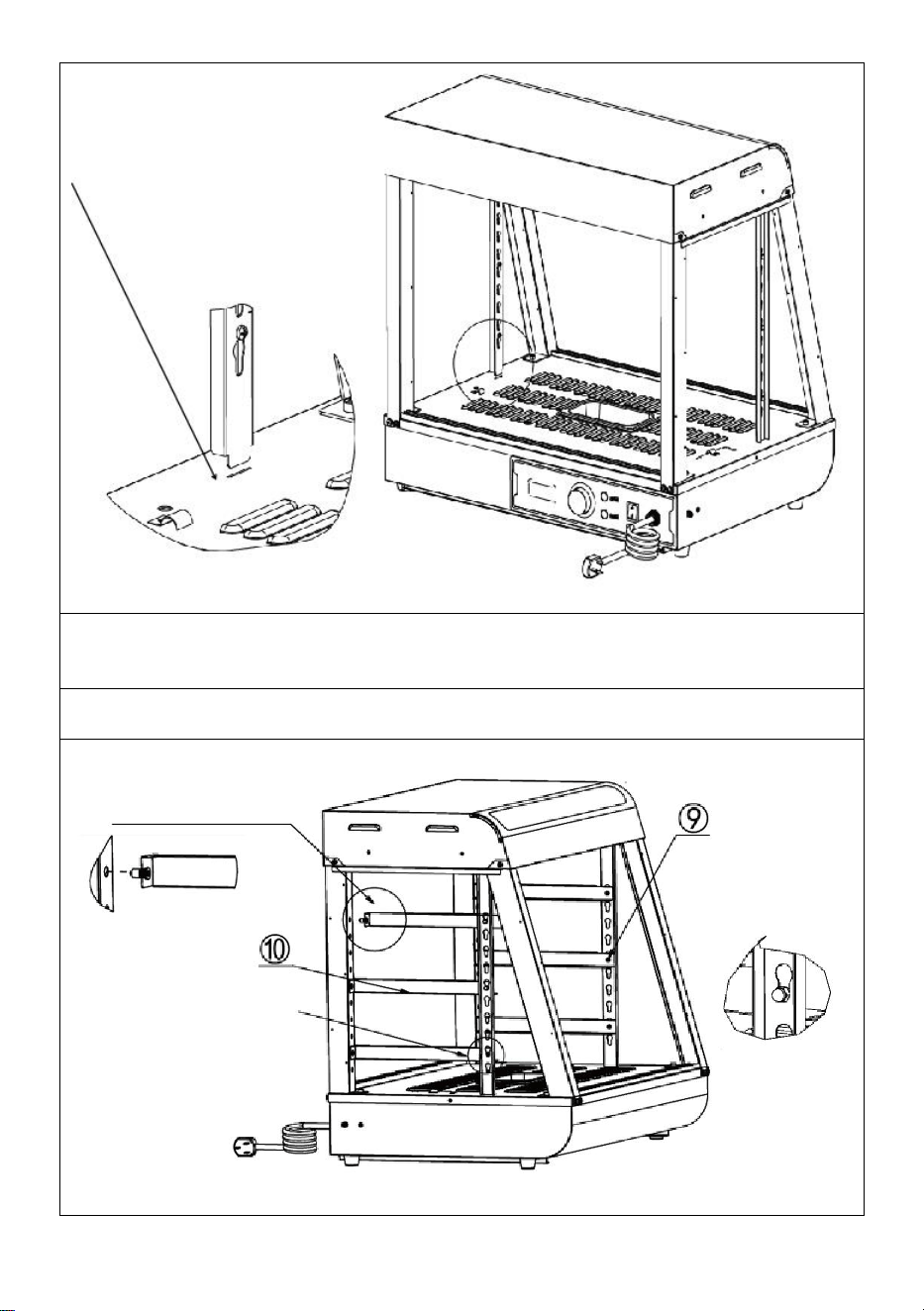
1. Align the two left and right shelf pillars "⑧" in the same way in the
direction of Figure A, then insert them diagonally into the reserved holes
on the top until they are fully inserted, and then align them.
Note: The position of accessory No. 8 is as shown in the figure. The big
hole of the gourd hole is facing up, the small hole is facing down, and the
groove is facing the outside of the machine!
⑧ (2PCS)
1
- 17 -
2. Refer to Figure B and align the bottom of the column with the reserved
hole in the base plate and place it to complete the installation.
Step 7
2
2
1
- 18 -
1. First insert the ram nail on the front part of the part into the reserved
hole of the column as shown below.
Note: Place the protruding part of the I-shaped nail on the shelf bracket
toward the outside of the machine for installation!
2. Then, insert the buckle nail at the rear of the part into the gourd mouth
as shown in the picture below.
⑨ (3PCS)
⑩ (3PCS)
Step 8
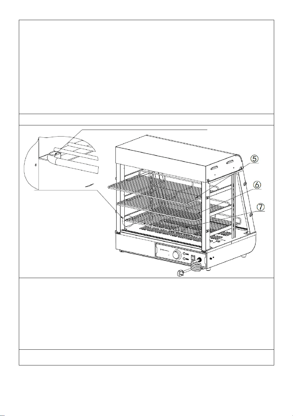
1. Place the parts "
⑤
,
⑥
,
⑦
" on the shelf bracket according to the
positions shown in the picture, and push them into the reserved slots as
shown in the picture.
⑤
(1PCS)
⑥
(1PCS)
⑦
(1PCS)
Step 9 (601 602 603)
1
- 19 -
1. First, insert the front and rear glass sliding doors diagonally into the
card slot set at the top, as shown in "Figure A"; after inserting it to the
extreme position, align the falling glass with the card slot below that is
horizontal and vertical to the top card slot, as shown in "Figure A". The
installation is completed as shown in "Figure B". A total of four glass
sliding doors at the front and rear are installed in the same way.
⑪
(4PCS)
1
Pic A
2
- 20 -
Notice:
1. You need to install the inner piece of glass first and then the outer
piece of glass;
2. When installing, the upper card slot should be aligned horizontally and
vertically with the lower card slot!
Step 9 (60S)
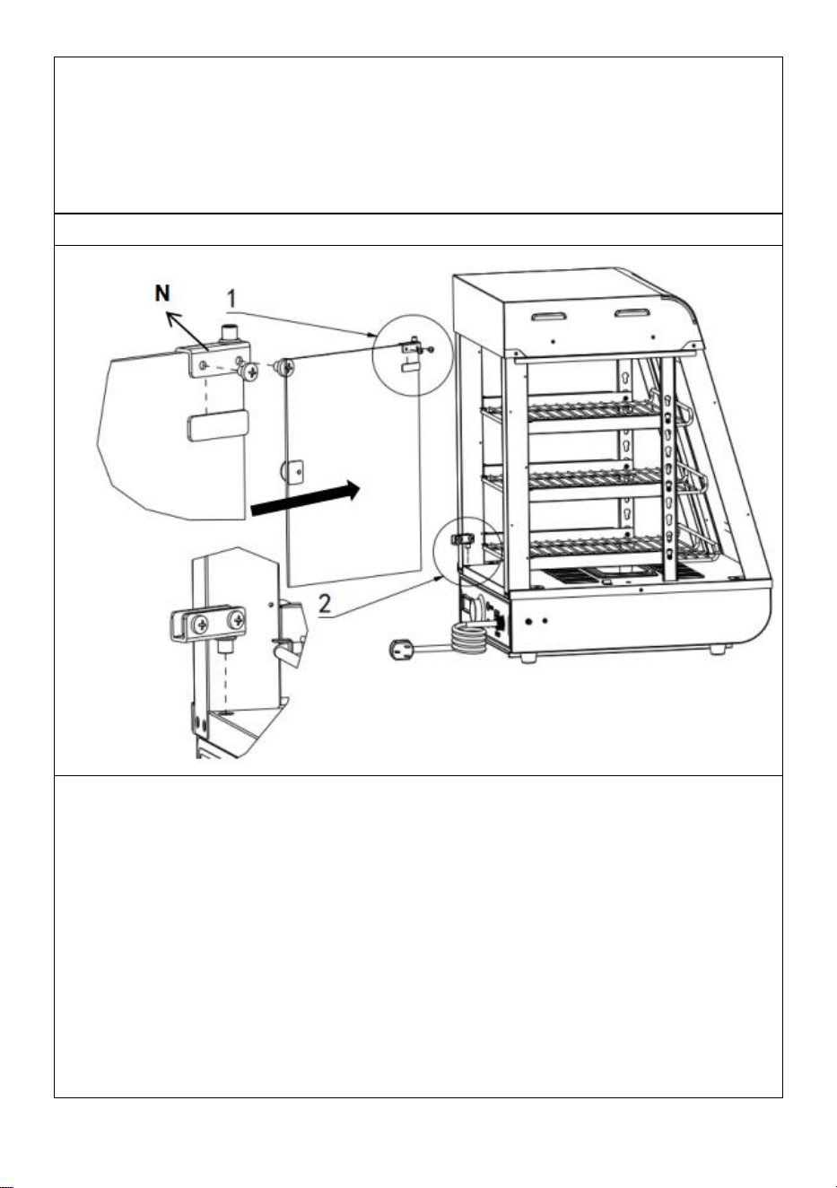
1. First install the upper glass door hinge on the top of the glass flip door
and tighten the screws.Then prepare the lower door hinge in the
corresponding position.Finally, push the glass flip door into the prepared
position of the lower hinge, and then tighten the screws of the lower
hinge!
N(One for each top and bottom)
Install the door handle before the glass door(1PCS)
- 21 -
Step 10
2. First install the upper glass door hinge on the top of the glass flip door
and tighten the screws.Then prepare the lower door hinge in the
corresponding position.Finally, push the glass flip door into the prepared
position of the lower hinge, and then tighten the screws of the lower
hinge!
N(One for each top and bottom)
Install the door handle before the glass door(1PCS)
Installation completed
The position of the electrical parts is designed at that time, the
company reserves the right to change the design of the evaluation,
when the design changes and does not improve the manual in time,
hope customers understand!
- 22 -
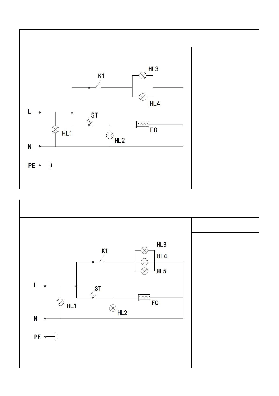
10. Circuit diagram
SC-CJ-60S/SC-CJ-601 Electrical schematic diagram
Illustrate
K1: Light switch
HL1: Power
indicator light
HL2: Heating
indicator light
HL3 warm light
ceiling lamp
HL4:LED light
tube
FC: heating tube
ST: Thermostat
SC-CJ-602/SC-CJ-603 Electrical schematic diagram
Illustrate
K1: Light switch
HL1: Power
indicator light
HL2: Heating
indicator light
HL3: Warm light
ceiling lamp 1
HL4: Warm light
ceiling lamp 2
HL5:LED light
tube
FC: heating tube
ST: Thermostat

- 23 -
11. Fault analysis and troubleshooting:
NO.
Fault phenomenon
Reason
Method of
exclusion
01
The indicator light
does not light up
when the device is
turned on.
Power switch fuse
blown
①Replace with a
suitable fuse
②Plug in the power
cord firmly
02
The green and red
indicator lights are on
at the same time and
the temperature does
not rise.
The electric
heating tube
wiring is loose and
the electric
heating tube is
burned out.
①
Tighten the electric
heating pipe wiring
bolts.
②
Replace the
electric heating tube
03
The work indicator
light stays on and the
temperature rise
cannot be controlled.
Thermostat failure
①
Replace the
thermostat
04
The indicator light is
off and the
temperature control is
normal
Indicator light
burned out
①Replace the
indicator light
05
It cannot
automatically keep
warm.
Thermostat failure
①Replace the
thermostat
06
There is a tingling
sensation in the
hands due to leakage
from the casing.
The insulation is
damp or the inner
conductor is in
contact with the
outer shell.
①Send it to the
maintenance
department for repair.
07
The light does not
come on or flickers.
The cable
interface is not
connected or has
poor contact.
①
Plug it in tightly
- 24 -
Please keep this manual properly
Manufacturer: Shanghaimuxinmuyeyouxiangongsi
Address: Shuangchenglu 803nong11hao1602A-1609shi, baoshanqu,
shanghai 200000 CN.
Imported to AUS: SIHAO PTY LTD. 1 ROKEVA STREETEASTWOOD
NSW 2122 Australia
Imported to USA: Sanven Technology Ltd. Suite 250, 9166 Anaheim
Place, Rancho Cucamonga, CA 91730
REP
UK
YH CONSULTING LIMITED. C/O YH Consulting
Limited Office 147, Centurion House, London
Road, Staines-upon-Thames, Surrey, TW18 4AX
REP
EC
E-CrossStu GmbH
Mainzer Landstr.69,
60329 Frankfurt am Main.
Note: The above problems are only for analysis and reference use. Do
not deal with them by yourself. Relevant professionals are required to
conduct troubleshooting and repairs. In case of safety abnormalities such
as leakage, the power supply should be cut off immediately and use
should be stopped!


SCCJ602/SCCJ603
Modèle:SCCJ60S/SCCJ601/
Affichageduchauffeplats
Assistancetechniqueetcertificatdegarantieélectroniquewww.vevor.com/support
"Économisezlamoitié","Moitiéprix"outouteautreexpressionsimilairequenousutilisonsnereprésente
qu'uneestimationdeséconomiesdontvouspourriezbénéficierenachetantcertainsoutilscheznouspar
rapportauxgrandesmarquesetnesignifiepasnécessairementcouvrirtouteslescatégoriesd'outilsproposés.
parnous.Nousvousrappelonsdevérifierattentivementlorsquevouspassezunecommandechez
noussivouséconomisezréellementlamoitiéparrapportauxgrandesmarques.
Nouscontinuonsànousengageràvousfournirdesoutilsàdesprixcompétitifs.
Machine Translated by Google

Machine Translated by Google

BESOIND'AIDE?CONTACTEZNOUS!
SCCJ602
SCCJ603
Vousavezdesquestionssurlesproduits?Besoind'uneassistancetechnique?N'hésitez
pasànous
contacter:Supporttechniqueetcertificatdegarantieélectronique
www.vevor.com/support
SCCJ60S SCCJ601
Modèle:SCCJ60S/SCCJ601/SCCJ602/SCCJ603.
Affichageduchauffeplats
Ils'agitdesinstructionsoriginales,veuillezlireattentivementtoutesles
instructionsdumanuelavantdel'utiliser.VEVORseréserveuneinterprétation
clairedenotremanueld'utilisation.L'apparenceduproduitdépenddu
produitquevousavezreçu.Veuilleznouspardonnerquenousnevousinformerons
pluss'ilyadesmisesàjourtechnologiquesoulogiciellessurnotreproduit.
1
Machine Translated by Google

Rappelchaleureux
Pourgarantirqueceproduitneserapasrayépendantletransport,unfilmprotecteurestfixésur
lasurfacedelamachine.Veuillezretirertouslesfilmsprotecteursavantutilisation!
1.Moded'emploi:1.Leproduit
doitêtremisàlaterreentoutesécuritéavantutilisation!
2.Latensionutiliséeparleproduitdoitêtreconformeàlatensionnominale.
ÉLIMINATIONCORRECTE
Utilisationenintérieuruniquement
Ceproduitestsoumisauxdispositionsdeladirectiveeuropéenne2012/19/UE.Le
symbolereprésentantunepoubellebarréeindiquequeleproduitnécessite
unecollectesélectivedesdéchetsdansl'Unioneuropéenne.Cecis'applique
auproduitetàtouslesaccessoiresmarquésdecesymbole.Lesproduits
marquéscommetelsnepeuventpasêtrejetésaveclesorduresménagères
normales,maisdoiventêtredéposésdansunpointdecollectepourlerecyclagedes
appareilsélectriquesetélectroniques.
Avertissement:Pourréduirelerisquedeblessure,l'utilisateurdoitlire
attentivementlemanueld'instructions.
3.Lorsdechaqueutilisation,ajoutezdel'eaudanslebassind'eauaux2/3delacapacitéavant
demettresoustension.
4.Allumezl'alimentation,levoyantd'alimentationestallumé,allumezl'interrupteurdechauffage
decontrôledelatempératureetsélectionnezlatempératured'isolationdesalimentspouraugmenter
latempératuredel'espaceàl'intérieurdel'armoire.Grâceàlaconvectionnaturelle,latempérature
dechaquecouchepeutresterconstante.
2
Machine Translated by Google

3
dansl'utilisationdesmachinesetdeséquipements.
Ceproduitn'estpasdestinéàêtreutilisépardespersonnes(ycomprisdesenfants)avec
3.5Làoùiln'yapasdebondispositifdemiseàlaterre.
6.Précautionsparticulières:
Groupedelumière,ettoutesleslumièresserontallumées,cequipeutaméliorerl'affichage
fonctionnement,n'approchezpasvosmainsoud'autrespartiesducorpsàproximitédu
connaissance.
3.3Lieuxavecunvolumed'airexcessifetunepoussièreexcessive.
6.2Ilnepeutêtredémontéoumodifié.Ledémontersans
effet.
surfacedelamachinepouréviterlesbrûluresouautresblessures.
pouréviterundysfonctionnementdûàunemauvaiseutilisation:
essuyezlasurfacedel'armoireisolante.
1.Ildoitêtreutilisépardupersonneldésignéetdoitêtrecompétent
réparéparunprofessionnel.Nelefrappezpas.
dansl'eaupouréviterlesfuitesélectriques.
7.Siuneanomalieseproduitpendantl'utilisation,arrêtezdel'utiliseretdemandezàun
capacitésphysiques,sensoriellesoumentalesréduitesoumanqued’expérienceet
3.4Endroitsoùlatensiond'alimentationesttrèsinstable.
autorisationpeutprovoquerdesaccidentsgraves.
3.2Endroitsoùlatempératureesttropélevéeoutropbasse.
6.1Ceproduitestunappareilcommercialetneconvientpasàunusagedomestique
5.Pendantl'utilisation,sivousavezbesoind'éclairage,vouspouvezallumerl'interrupteurd'éclairagedu
9.Étantdonnéquelatempératuredel'équipementestrelativementélevéependant
6.Aprèsutilisation,l'alimentationdoitêtrecoupéelorsdunettoyagepouréviterlesaccidents;
3.Veuilleznepasinstalleretstockercetéquipementdanslesendroitssuivants
5.Ileststrictementinterditd'utiliserdesliquidessolublesdanslapeinturedecuissonpour
3.1Surunetableouuncomptoirinstable.
2.Soyezprudentlorsquevousdéplacezlamachine.S'ilyaundéfaut,cedoitêtre
4.L'appareilnedoitpasêtrenettoyéavecunjetd'eauniimmergé
professionnelpourledépanneravantdecontinueràl'utiliser.
2.Précautionsetentretien:
Machine Translated by Google

4
3.Conditionsnormalesd'environnementdetravail:1.La
températureambianteestde5à50etl'humiditérelativedel'airnedépassepas90
%;2.Tension
d'alimentation:110V±10%,fréquence:60±1%HZ.(220V±10%,fréquence:50
±1%)
4.Présentationduproduit:1.Ce
produitaundesignnovateuretunique,uneformed'arc,uneétagèreàgrilleréglable
multicouche,uneperspectiveenverreàquatrecôtés,ledessusutiliseunecarte
PCàhautetransparencerespectueusedel'environnementcommepanneaulumineux
transmettantlalumière.,etuntubeLEDblancestutiliséeninternepouraugmenterla
duréedevie;lesutilisateurspeuventmettredifférentescartespublicitairesselon
vosproprespréférencespouraugmenterlabeauté.Lastructurepratiquede
démontageetd'assemblageestfacileàutiliser,robusteetdurable,etfacileà
entretenir.Ildisposed'unetempératureconstanteenoptionetd'unaffichagedela
température.Laconceptiondudownlightàtubechaudsupérieurpeutrendrela
lumièreplusuniformeetelleestéquipéed'unecompensationhydratantepourgarder
lesalimentsfrais.C'estunéquipementspécialpourlaprésentationdesalimentsetlaconservationdelachaleur.
6.4Ilestinterditd'utiliserdesobjetsdursoupointuspourrayerleverre.
6.3L'alimentationdoitêtrecoupéeavantlenettoyagepouréviterlesfuitesaccidentelles.
5.Descriptiondessymboles:
Danscemanuel,dessymbolessontutiliséspourmettreenévidencetoutes
lesinstructionsdesécuritéetrecommandationsimportantesliéesàl'équipement.Pour
évitertoutrisqued'accident,deblessureoudedommagematériel,suivezces
instructionsavecunsoinparticulier.
Machine Translated by Google

(KW)
60
240
Fréquence
240
AC220
667*470*640
50
3085
60
Température
SCCJ601
120
240
Tension
86185F
(DANS)
Dimension
240
AC220
50
3085
86185F
86185F
Modèle
SCCJ60S
120
Pouvoir
1
3085
1,5
1210*470*64
1,5
50
(HZ)
AC220
SCCJ603
gamme
60
1.2
907*470*640
50
120
AC110
3085
AC110
AC110
AC220
(MM)
SCCJ602
385*490*640
60
0
120
AC110
86185F
7.Imaged'apparenceduproduit
SCCJ60S
6.Modèle,spécificationsetprincipauxparamètrestechniques:
SCCJ601
5
Machine Translated by Google
6
SCCJ602
SCCJ603
8.Schémadestructureduproduit
Machine Translated by Google

14
25
1
Goulotteàverreinclinée
dix
19
13
entempsopportun,nousespéronsvotrecompréhension!
02Emplacementpourcartetranslucide2
1
Colonned'étagère
1
Remarque:L'emplacementdescomposantsélectriquesestbasésurlaconceptionà
Basducapotsupérieur
24
Etanchéitéducoffretélectrique
2
Lecouverclesupérieur
EnformedeTenaluminium
Base
Nom
1
1
18
1
Listedesgraphiqueséclatés
07
1
2
Bacàscories
cloison
pilier
bouche
Pilieravant
1
porte
Nom
17
21
cetemps.Notresociétéseréserveledroitdemodifierlesconditionsdeparticipation
6W
1
Barredeguidagedebassin27temps
1
1
09Câblepriseaviation
06
23
4
1
Vitreavantcoulissante
15
1
QtéNo.
1
long
01
Goulotteàverredroite
Boîteélectrique
Verrelatéral
22Panneauxisolantslatéraux2
Quantité
1
12
Pieddemachinen°1
1
11
Montantarrière
28
05
Bassinde0,5L
Couverturetranslucide
ouverture
Rétroviseurdemontantarrière
Tabledebase
poignéedeporte
1
dessins.Silaconceptionestmodifiéeetquelesinstructionsnesontpasmisesàjourdansun
TubeLED600mm
Downlightultrafin
2
Tuyaudechauffage
1
4
4
16
plaque
Bouclierthermiquearrière
Imagemiroirdelafaceavant
03
1
1
26
20
Non.
04
08
plaque
7
Machine Translated by Google

C
Printempsnoir
H
Inoxydable
M5X14
g
enformedeT
aluminium
(4pièces)
(années60aucun)
ET
M5X14
(8pièces)(8pièces)
Nomenclaturedukitdepièces
Rondnoir
J.
têteronde
acier
M5
Inoxydable Silicone
Outilsàvis
poignée
desvis
Platnoir
M4X8
B
je
Carteenverre
(années60aucun)
(8pièces)
(1PCS)
D
(4pièces)
F
Noir
enacierrembourré
joint
(années60aucun)
desvis
boulonsàdouille
M5
(8PIÈCES)
hexagone
visàtêtemachineàlaver
UN
(8pièces)
Noir
titulaire
(16pièces)
machineàlaver
(8pièces)
M4X12
Applicableauxmodèles:SCCJ601,SCCJ602,SCCJ603,SCCJ60S
9.Schémad'installationduproduit:
8
Machine Translated by Google

9
Balle
Jeudecharnièresen
verre
Poignée
Montantavantgauche
1PCS
M.
Lorsdel'installation,vouspouveztrouverlesvisdontlescodesdansl'imagecidessus
correspondentauxcodesimprimésdansl'emballagedesvisselonlesvisrequisesdans
lesétapesd'installationpouruneinstallationfacile!
1PCS
Exclusif
Croixenacier
accessoire
vis
(1PCS)
Panneaude
portemagnétique
M5X18
(1pièces)
Montantavantdroit
Noir
L
Listedespiècesd'assemblage
Montantarrièredroit
60S
Inoxydable
Remarque:cequiprécèdecorrespondàtouslesaccessoirescontenusdanslepaquetd'accessoires.
Montantarrièregauche
chaque
hautetbas
K
(1PCS)
N
1PCS
Unpour
1PCS
Machine Translated by Google

dix
Supportd'étagèredroite
Tabletteinférieurelapluslongue
Colonned'étagère
2pièces
(unchacun)
1PCS
Portevitréearrière
Étagèredumilieumoyenne
Vitreavantetarrièrecoulissante
accessoire
3PIÈCES
60S
1PCS
Etagèresupérieurelapluscourte
2pièces
Verrelatéral
Porteavantrabattableenverre
portes(années60aucune)
1PCS
Supportd'étagèregauche
Exclusif
3PIÈCES
4PIÈCES
Machine Translated by Google

11
Schémad'installationuniverselsérieSCCJ60
Schémad'installationuniverselsérieSCCJ60
L
G(4pièces)
F(2pièces)
Étape1(601602603)
M.
Je(1pièces)
K(1PIÈCES)
L(1PIÈCES)
Remarque:cequiprécèdeconcernetouslesaccessoiresinclusdanslepaquetd'accessoires.
K
M(1PIÈCES)
Veuillezvérifiersilesaccessoiressontcompletsavantl'installation!
Étape1(60s)
Machine Translated by Google

12
2.Selonl'ordredel'image,utilisezlesviscorrespondantes:«D,A,B»pourverrouillerles
accessoires:«,»respectivementsurlestrousd'écrouréservés.
3.ImagedétailléeA
(1pièce)(1
pièce)
Un(4pièces)
B(4pièces)
Remarque:lorsdel'installationdescolonnesdesdeuxcôtés,veuilleznoterquelecôtéavecdes
trousdanslacolonnefaitfaceàl'extérieurdelamachinepour
installation!
1.Passezleconnecteurducordonlumineuxdépassantdelabaseàtraverslacolonneetaccrochez
leaudessusdelacolonne.
ImagedétailléeA
E(spécification:M5*14)
Étape2
D(4PIÈCES)
Machine Translated by Google

13
Remarque:lorsdel'installationdescolonnesdesdeuxcôtés,veuilleznoterquelecôtéavecdestrous
danslacolonnefaitfaceàl'extérieurdelamachinepour
installation!
(1PIÈCES)
(1PIÈCES)
Un(4pièces)
ImagedétailléeA
1.Selonl'ordredel'image,utilisezlesviscorrespondantes:«D,A,B»pourverrouillerlesaccessoires:
«,»surlestrousd'écrouréservésrespectivement.
Spécification
n:M5*14
ImagedétailléeA
D(4PIÈCES)
B(4pièces)
Étape3
Machine Translated by Google

14
Spécification:
M5*14
ImagedétailléeB
1.Utilisezlavis«C»pourfixerlesquatrecolonnesauxécrousréservéssurlabase.
image
B
Détail
ImagedétailléeA
delamêmemanièrequelemontrel'imagedétaillée.
Étape4
C(4pièces)
Machine Translated by Google

1
1
1.Connectezleconnecteurdefildépassantducouverclesupérieurauconnecteur
accrochéàlacolonneetserrezle,puisinsérezleconnecteurconnectédans
lacolonneetcachezle.
Spécification:
ImagedétailléeA
ImagedétailléeA
Étape5
M4*8
15
Machine Translated by Google

1
Étape6
Remarque:Lapositiondel'accessoiren°8estcelleindiquéesurlafigure.Legrandtrou
dutroudegourdeesttournéverslehaut,lepetittrouesttournéverslebasetlarainureest
tournéeversl'extérieurdelamachine!
E(4pièces)
1.Placezlecapotsupérieursurlesquatremontantsverticaux,puisutilisezles«visE»
pourfixerlecapotsupérieuretlesmontantsverticaux(quatreautotal).
1.Alignezlesdeuxpiliersd'étagèregaucheetdroit«»delamêmemanièredans
lesensdelafigureA,puisinsérezlesendiagonaledanslestrousréservéssurledessus
jusqu'àcequ'ilssoientcomplètementinsérés,puisalignezles.
(2pièces)
16
Machine Translated by Google

Étape7
2.ReportezvousàlafigureBetalignezlebasdelacolonneavecletrouréservé
danslaplaquedebaseetplacezlapourterminerl'installation.
1
2
2
17
Machine Translated by Google

1
Remarque:placezlapartiesaillanteduclouenformedeIsurlesupportd'étagèrevers
l'extérieurdelamachinepourl'installation!
Étape8
2.Ensuite,insérezlecloudeboucleàl'arrièredelapiècedansl'embouchuredelagourde
commeindiquésurl'imagecidessous.
(3pièces)
(3pièces)
1.Insérezd'abordleclouàvérinsurlapartieavantdelapiècedansletrouréservédela
colonnecommeindiquécidessous.
1.Placezlespièces«,,»surlesupportd'étagèreselonlespositions
indiquéessurl'image,etpoussezlesdanslesfentesréservéescommeindiquésurl'image.
(1PIÈCE)(1PIÈCE)
(1PIÈCE)
Étape9(601602603)
18
Machine Translated by Google

2
1
1.Toutd'abord,insérezlesportescoulissantesenverreavantetarrièreendiagonaledansl'emplacement
pourcartesituéenhaut,commeindiquésurla«FigureA»;aprèsl'avoirinséréàl'extrême,alignezleverre
tombantaveclafentepourcarteendessousquiesthorizontaleetverticaleparrapportàlafentepourcarte
supérieure,commeindiquédansla«FigureA».L'installationestterminéecommeindiquédansla«Figure
B».Autotal,quatreportescoulissantesenverreàl'avantetàl'arrièresontinstalléesdelamêmemanière.
(4pièces)
PhotoA
19
Machine Translated by Google

20
Étape9(60S)
1.Installezd'abordlacharnièresupérieuredelaporteenverresurledessusdelaporte
battanteenverreetserrezlesvis.Préparezensuitelacharnièreinférieurede
laportedanslapositioncorrespondante.Enfin,poussezlaportebattanteenverredans
lapositionpréparéedelacharnièreinférieure,etpuisserrezlesvisdelacharnière
inférieure!
1.Vousdevezd’abordinstallerlapiècedeverreintérieure,puislapiècedeverre
extérieure;2.
Lorsdel'installation,l'emplacementpourcartesupérieurdoitêtrealignéhorizontalementet
verticalementavecl'emplacementpourcarteinférieur!
Avis:
N(unpourchaquehautetbas)
Installezlapoignéedeporteavantlaportevitrée(1pièce)
Machine Translated by Google
21
N(unpourchaquehautetbas)
Installezlapoignéedeporteavantlaportevitrée(1pièce)
2.Installezd'abordlacharnièresupérieuredelaporteenverresurledessusdelaporte
battanteenverreetserrezlesvis.Préparezensuitelacharnièreinférieurede
laportedanslapositioncorrespondante.Enfin,poussezlaportebattanteenverredans
lapositionpréparéedelacharnièreinférieure,etpuisserrezlesvisdelacharnière
inférieure!
Étape10
installationterminée
Lapositiondespiècesélectriquesestconçueàcemomentlà,lasociétéseréserve
ledroitdemodifierlaconceptiondel'évaluation,lorsquelaconceptionchangeet
n'améliorepaslemanuelàtemps,j'espèrequelesclientscomprendront!
Machine Translated by Google

SCCJ602/SCCJ603Schémaélectrique
Illustrer
HL4:Plafonnier
lumièrechaude2
HL5:tubelumineux
àLED
HL3:Plafonnier
lumièrechaude1
K1:interrupteurd'éclairage
Illustrer
FC:tubechauffant
K1:interrupteurd'éclairage
HL1:Puissance
HL2:Voyant
dechauffe
voyant
voyant
HL1:Puissance
HL2:Voyant
dechauffe
Plafonnierlumière
chaudeHL3
FC:tubechauffant
HL4:tubelumineux
LED
SCCJ60S/SCCJ601Schémaélectrique
ST:Thermostat
ST:Thermostat
10.Schémadecircuit
22
Machine Translated by Google

l'interfacen'estpas
Remplacerparun
fusibleapproprié
02
lecontrôledelatempérature
estnormal
lalumièrerestealluméeetla
montéeentempérature
nepeutpasêtrecontrôlée.
Ilyaunesensationde
picotementdans
départementderéparation.
NON.Phénomènededéfaut
L'indicateurdetravail
Lecâblagedu
tubede
chauffageélectriqueest
lâcheetlefilélectrique
Remplacezle
voyant
humideouleconducteur
intérieuresten
soufflé
03
05
contactavecle
Branchezlefermement
Levoyantnes'allume
paslorsquel'appareil
est
Levoyantestéteintetle
chaud.
Lecable
Raison
Serrezlesboulonsdu
câblagedutuyaude
chauffageélectrique.
Remplacezletubechauffantélectrique
Letubechauffant
estgrillé.
Ilnepeut
pasconserverautomatiquement
Envoyezleàla
maintenance
Lalumièrenes'allume
pasouscintille.
exclusion
allumé.
Remplacezle
thermostat
Remplacezle
thermostat
mainsenraisond’unefuite
duboîtier.
07
Fusibledel'interrupteurd'alimentation
Panneduthermostat
Panneduthermostat
coqueextérieure.
connectéouaun
mauvaiscontact.
04
Méthodede
Branchezfermementle
cordond'alimentation
Lesvoyantsvertet
rougesontallumésen
mêmetempsetla
températuren'augmente
pas.
Levoyantest
grillé
01
L'isolationest
06
11.Analysedesdéfautsetdépannage:
23
Machine Translated by Google
REPRÉSENTANTDUROYAUMEUNI
REPRÉSENTANTCE
ImportéauxÉtatsUnis:SanvenTechnologyLtd.Suite250,9166AnaheimPlace,
RanchoCucamonga,CA91730
YHCONSULTINGLIMITÉE.C/OYHConsultingLimited
Bureau147,CenturionHouse,LondonRoad,Staines
uponThames,Surrey,TW184AX
ECrossStuGmbH
MainzerLandstr.69,
60329FrancfortsurleMain.
Veuillezconservercorrectementcemanuel
ImportéenAustralie:SIHAOPTYLTD.1ROKEVASTREETASTWOODNSW2122
Australie
Fabricant:ShanghaimuxinmuyeyouxiangongsiAdresse:
Shuangchenglu803nong11hao1602A1609shi,baoshanqu,shanghai200000CN.
Remarque:lesproblèmescidessussontuniquementdestinésàl'analyseetàl'utilisation
deréférence.Nevousenoccupezpasvousmême.Desprofessionnelscompétents
sontrequispoureffectuerledépannageetlesréparations.Encasd'anomaliesdesécurité
tellesqu'unefuite,l'alimentationélectriquedoitêtreimmédiatementcoupéeet
l'utilisationdoitêtrearrêtée!
24
Machine Translated by Google

Machine Translated by Google


Speisenwärmer-Display
„Sparen Sie die Hälfte“, „Halber Preis“ oder andere ähnliche Ausdrücke, die wir verwenden, stellen nur eine
Schätzung der Ersparnis dar, die Sie beim Kauf bestimmter Werkzeuge bei uns im Vergleich zu den großen
Topmarken erzielen können, und decken nicht unbedingt alle von uns angebotenen Werkzeugkategorien ab. Wir
möchten Sie freundlich daran erinnern, bei Ihrer Bestellung bei uns sorgfältig zu prüfen, ob Sie im Vergleich
zu den großen Topmarken tatsächlich die Hälfte sparen.
Wir sind weiterhin bestrebt, Ihnen Werkzeuge zu wettbewerbsfähigen Preisen anzubieten.
Modell:SC-CJ-60S/SC-CJ-601/
SC-CJ-602/SC-CJ-603
Technischer Support und E-Garantie-Zertifikat www.vevor.com/support
Machine Translated by Google

Machine Translated by Google

- 1 -
Haben Sie Fragen zum Produkt? Benötigen Sie technischen Support? Bitte kontaktieren Sie
uns:
Technischer Support und E-Garantie-Zertifikat www.vevor.com/
support
SC-CJ-603
SC-CJ-601
Dies ist die Originalanleitung. Bitte lesen Sie alle Anweisungen sorgfältig durch,
bevor Sie das Gerät in Betrieb nehmen. VEVOR behält sich eine klare Auslegung unserer
Bedienungsanleitung vor. Das Erscheinungsbild des Produkts richtet sich nach
dem Produkt, das Sie erhalten haben. Bitte verzeihen Sie uns, dass wir Sie nicht erneut
informieren, wenn es Technologie- oder Software-Updates für unser Produkt gibt.
MODELL: SC-CJ-60S/SC-CJ-601/SC-CJ-602/SC-CJ-603
SC-CJ-602SC-CJ60S
Speisenwärmer-Display
Brauchen Sie Hilfe? Kontaktieren Sie uns!
Machine Translated by Google

- 2 -
2. Die vom Produkt verwendete Spannung muss mit der Nennspannung übereinstimmen.
Um sicherzustellen, dass dieses Produkt während des Transports nicht zerkratzt wird, ist auf der
Oberfläche der Maschine eine Schutzfolie angebracht. Bitte reißen Sie vor dem Gebrauch alle
Schutzfolien ab!
Nur Innen benutzen
3. Füllen Sie bei jedem Gebrauch vor dem Einschalten 2/3 der Kapazität des Wasserbeckens mit
Wasser auf.
Dieses Produkt unterliegt den Bestimmungen der europäischen Richtlinie
2012/19/EU. Das Symbol einer durchgestrichenen Mülltonne weist
darauf hin, dass dieses Produkt in der Europäischen Union einer getrennten
Müllentsorgung unterliegt. Dies gilt für das Produkt und alle mit diesem
Symbol gekennzeichneten Zubehörteile. So gekennzeichnete Produkte dürfen
nicht im normalen Hausmüll entsorgt werden, sondern müssen an einer
Sammelstelle für das Recycling von elektrischen und elektronischen Geräten
abgegeben werden.
1. Gebrauchsanweisung: 1. Das
Produkt muss vor der Verwendung sicher geerdet werden!
KORREKTE ENTSORGUNG
Warnung: Um das Verletzungsrisiko zu verringern, muss der Benutzer
die Bedienungsanleitung sorgfältig lesen.
4. Schalten Sie den Strom ein, die Betriebsanzeige leuchtet, drehen Sie den Heizschalter der
Temperaturregelung und wählen Sie die Isoliertemperatur der Lebensmittel, um die Temperatur im
Schrankinneren zu erhöhen. Durch natürliche Konvektion kann die Temperatur jeder Schicht konstant
gehalten werden.
Herzliche Erinnerung
Machine Translated by Google

2. Vorsichtsmaßnahmen und Wartung:
Dieses Produkt ist nicht für den Gebrauch durch Personen (einschließlich Kinder) bestimmt mit
2. Seien Sie vorsichtig, wenn Sie die Maschine bewegen. Wenn ein Fehler auftritt, muss er
4. Das Gerät darf nicht mit einer Wasserspritzpistole gereinigt oder in Wasser getaucht werden.
3.5 Wenn keine gute Erdungsvorrichtung vorhanden ist.
5. Es ist strengstens verboten, Flüssigkeiten zu verwenden, die in Backfarbe löslich sind, um
Wissen.
3. Bitte installieren und lagern Sie dieses Gerät nicht an den folgenden Orten
bringen Sie Ihre Hände oder andere Körperteile während des Betriebs nicht in die Nähe des
Lichtgruppe, und alle Lichter werden eingeschaltet, was die Anzeige verbessern kann
3.1 Auf einem instabilen Tisch oder einer instabilen Theke.
Oberfläche der Maschine, um Verbrennungen oder andere Verletzungen zu vermeiden.
Wirkung.
3.2 Orte, an denen die Temperatur zu hoch oder zu niedrig ist.
6.1 Dieses Produkt ist ein kommerzielles Gerät und nicht für den Heimgebrauch geeignet
7. Wenn während des Gebrauchs eine Anomalie auftritt, beenden Sie die Verwendung und fragen Sie einen
Erlaubnis kann zu schweren Unfällen führen.
1. Es sollte von ausgewiesenem Personal bedient werden und sollte kompetent sein
3.4 Orte, an denen die Versorgungsspannung sehr instabil ist.
von einem Fachmann reparieren lassen. Keine Schläge darauf schalten.
eingeschränkte körperliche, sensorische oder geistige Fähigkeiten oder mangelnde Erfahrung und
im Wasser, um Stromlecks zu verhindern.
5. Wenn Sie während des Gebrauchs Beleuchtung benötigen, können Sie den Beleuchtungsschalter des
9. Da die Temperatur des Gerätes während der
um Fehlfunktionen durch Fehlbedienung zu vermeiden:
Wischen Sie die Oberfläche des Isolierschranks ab.
6. Besondere Vorsichtsmaßnahmen:
3.3 Orte mit übermäßigem Luftvolumen und übermäßigem Staub.
6. Nach Gebrauch muss beim Reinigen die Stromzufuhr unterbrochen werden, um Unfälle zu vermeiden;
6.2 Das Gerät kann nicht zerlegt oder modifiziert werden. Eine Demontage ohne
Lassen Sie das Problem von einem Fachmann beheben, bevor Sie es weiter verwenden.
beim Einsatz von Maschinen und Geräten.
- 3 -
Machine Translated by Google

3. Normale Arbeitsbedingungen: 1. Die Umgebungstemperatur
beträgt 5–50 °C und die relative Luftfeuchtigkeit nicht mehr als 90 %. 2.
Versorgungsspannung:
110 V ± 10 %, Frequenz: 60 ± 1 % Hz. (220 V ± 10 %, Frequenz: 50 ± 1 %)
5. Symbolbeschreibung: In
dieser Anleitung werden Symbole verwendet, um alle wichtigen Sicherheitshinweise
und Empfehlungen zum Gerät hervorzuheben. Um das Risiko von Unfällen, Personen- oder
Sachschäden zu vermeiden, befolgen Sie diese Anweisungen mit besonderer
Sorgfalt.
6.4 Es ist verboten, das Glas mit harten oder scharfen Gegenständen zu zerkratzen.
6.3 Um unbeabsichtigte Leckagen zu vermeiden, muss vor der Reinigung die Stromzufuhr
unterbrochen werden.
4. Produkteinführung: 1. Dieses
Produkt hat ein neuartiges und einzigartiges Design, eine Bogenform, ein
mehrschichtiges verstellbares Gitterregal und eine vierseitige Glasperspektive. Die
Oberseite verwendet eine umweltfreundliche, hochtransparente PC-Platine als lichtdurchlässige
Lichtplatte und im Inneren wird eine weiße LED-Röhre verwendet, um die Lebensdauer zu
verlängern. Benutzer können verschiedene Werbekarten nach Ihren eigenen
Wünschen anbringen, um die Schönheit zu erhöhen. Die praktische Demontage- und
Montagestruktur ist einfach zu bedienen, robust und langlebig und leicht zu warten. Es
verfügt über eine optionale konstante Temperatur und eine Temperaturanzeige. Das
Design der oberen Warmröhren-Downlights kann das Licht gleichmäßiger machen und
ist mit einer Feuchtigkeitskompensation ausgestattet, um die Lebensmittel frisch zu
halten. Es ist eine spezielle Ausrüstung für die Präsentation und Wärmekonservierung von Lebensmitteln.
- 4 -
Machine Translated by Google

7. Produktbild
- 5 -
Frequenz
120
AC110-
240
AC220-
240
50
60
SC-CJ-602
Temperatur
AC220-
385*490*640
60
86-185F
Stromspannung
86-185F
AC110-
0
Abmessungen
(IN)
120
AC110-
60
907*470*640
Leistung
30-85ÿ
SC-CJ-603
Modell
AC220-
1.2
50
SC-CJ-60S
(HZ)
120
1
30-85ÿ
1210*470*64
Reichweite
50
240
AC220-
86-185F
1.5
240
30-85ÿ
1.5
50
SC-CJ-601
AC110-
(MM)
120
86-185F
30-85ÿ
(KW)
60
667*470*640
SC-CJ-60S
6. Modell, Spezifikationen und wichtigste technische Parameter:
SC-CJ-601
Machine Translated by Google

- 6 -
SC-CJ-602
SC-CJ603
8.Produktstrukturdiagramm
Machine Translated by Google

Heizungsrohr
4
Obere Abdeckung
Designs. Wenn das Design geändert wird und die Anweisungen nicht in einem aktualisierten
1
Obere Abdeckung unten
Abdichtung von Schaltkästen
2
1
Durchscheinende Abdeckung
1
Base
Aluminium T-förmig
NEIN.
Glasrutsche geneigt
10
19
1
25
1
02 Durchsichtiger Kartensteckplatz 2
24
Regalsäule
13
Spiegelbild der Vorderseite
21
6W
27-Takt-Beckenführungsschiene
1
17
01
23
06
4
Menge Nr.
1
1
09 Luftfahrt-Steckerkabel
2
Schlackenwanne
1
18
1
07
Tür
Menge
Partition
Mund
1
Vordere Säule
Säule
1
22 Seitliche Dämmplatten 2
1
Maschinenfuß Nr. 1
Explosionszeichnungsliste
05
0,5L-Becken
11
Hintere Säule
28
15
1
1
1
Frontglasschiebetür
Glasrutsche gerade
Name
Elektrische Box
Seitenglas
12
Unser Unternehmen behält sich das Recht vor, die teilnehmenden
lang
Hitzeschild hinten
03
1
26
16
zeitnah, wir hoffen auf Ihr Verständnis!
Platte
08
Platte
14
1
20
04
Türschnalle
1
Öffnung
Name
Rückspiegel an der Säule
Basistabelle
1
Hinweis: Die Lage der elektrischen Komponenten richtet sich nach der Bauart
4
Ultradünnes Downlight
LED Röhre 600mm
2
- 7 -
Machine Translated by Google

Waschmaschine
Schwarz
Halter
(8 Stück)
M5X14
A
Kopfschrauben
(8 Stück)
Edelstahl Silikon
handhaben
(4 Stück)
T-förmig
M5X14
C
Schwarzer Frühling
G
(60er keine)
(1 Stück)
Glaskarte
Schwarz flach
D
M4X8
Schwarz
ICH
(60er keine)
J
Stahl
runder Kopf
Innensechskantschrauben
M5 M5
Schraubwerkzeuge
ÿ8 Stückÿ
(8 STÜCK)
Stahl gepolstert
F
Schrauben
B
(4 Stück)
Dichtung
(60er keine)
Schrauben
M4X12
H
Edelstahl
Waschmaschine
(8 Stück)
Aluminium
ÿ16 Stückÿ
(8 Stück)
UND
Stückliste für Teilesätze
Schwarzes Rund
Hexagon
- 8 -
Gilt für Modelle: SC-CJ-601, SC-CJ-602, SC-CJ-603, SC-CJ-60S
9.Produktinstallationsdiagramm:
Machine Translated by Google

- 9 -
(1 Stück)
ÿ
Zur einfachen Installation können Sie während der Installation die Schrauben finden, deren Codes
im Bild oben mit den auf der Schraubenverpackung aufgedruckten Codes übereinstimmen.
Entsprechend den in den Installationsschritten erforderlichen Schrauben finden Sie sie!
K N
1 STÜCK
Linke vordere Säule
Ball
Glasscharnier-
Set
1 STÜCK
M5X18
(1 Stück)
M
Rechte Vordersäule
60er Jahre
Edelstahl
ÿ
(1 Stück)
schrauben
Zubehörteil
Hinweis: Oben aufgeführte Zubehörteile sind alle im Zubehörpaket enthaltenen Zubehörteile.
ÿ
Linke hintere Säule
Rechte hintere Säule
Magnet-
Türverkleidung
Schwarz
Baugruppen-Stückliste
ÿ
Handhaben
Eins für
1 STÜCK 1 STÜCK
M
Exklusiv
Stahlkreuz
jeweils
oben und unten
Machine Translated by Google

- 10 -
Unteres Regal-längste
3 STK
4 STÜCK
ÿ
Exklusiv
Regalsäule
ÿ
ÿ
1 STÜCK
Türen (60er keine)
ÿ
Mittleres Regal - mittel
Seitenglas
ÿFrontglas-Klapptür
ÿ
3 STK
ÿ
ÿ
1 STÜCK
60er Jahre
Oberes Regal - kürzeste
2 STK
Glasschiebetüren vorn und hinten
Zubehörteil
ÿHintere Glastür
2 STK
1 STÜCK
Regalträger-links
(je eine)
ÿ
Regalträger rechts
Machine Translated by Google

- 11 -
ÿ
L (1 STK)
K (1 STK)
Schritt 1 (601 602 603)
Schritt 1 (60 s)
Bitte prüfen Sie vor der Montage die Vollständigkeit des Zubehörs!
Hinweis: Die oben genannten Zubehörteile sind alle im Zubehörpaket enthalten.
M (1 STK)
K
M
G (4 STK)
Universelles Installationsdiagramm der SC-CJ-60-Serie
Universelles Installationsdiagramm der SC-CJ-60-Serie
M
F (2 STK)
Ich (1 STK)
Machine Translated by Google

- 12 -
A (4 STK)
3.Detailbild A ÿ (1
STK) ÿ (1
STK)
Installation!
Schritt 2
Hinweis: Bei der Montage der Säulen auf beiden Seiten ist darauf zu achten, dass die
Seite mit den Löchern in der Säule zur Außenseite der Maschine zeigt.
2. Befestigen Sie die Zubehörteile „ÿ, ÿ“ gemäß der Reihenfolge im Bild mit den
entsprechenden Schrauben „D, A, B“ an den dafür vorgesehenen Mutternlöchern.
1. Führen Sie den aus der Basis herausragenden Lichtkabelanschluss durch die
Säule und hängen Sie ihn über die Säule.
Detailbild A
B (4 STK)
D (4 STK)
E (Spezifikation: M5*14)
Machine Translated by Google
- 13 -
ÿ (1 STK) ÿ
(1 STK)
Installation!
1. Befestigen Sie die Zubehörteile „ÿ, ÿ“ gemäß der Reihenfolge im Bild mit den
entsprechenden Schrauben „D, A, B“ an den dafür vorgesehenen Mutternlöchern.
A (4 STK)
Detailbild A
Hinweis: Bei der Montage der Säulen auf beiden Seiten ist darauf zu achten, dass die
Seite mit den Löchern in der Säule zur Außenseite der Maschine zeigt.
Spezifikation
Nr.: M5*14
Detailbild A
D (4 STK)
B (4 STK)
Schritt 3
Machine Translated by Google

- 14 -
Detailbild B
M5*14
B
1.Befestigen Sie die vier Säulen mit der Schraube „C“ an den dafür vorgesehenen Muttern an der Basis
Bild
Spezifikation:
Detail
Detailbild A
C (4 STK)
Schritt 4
auf die gleiche Weise, wie in der Detailabbildung gezeigt.
Machine Translated by Google
1
1
1. Verbinden Sie den aus der oberen Abdeckung herausragenden Kabelverbinder mit
dem an der Säule hängenden Verbinder und ziehen Sie ihn fest, stecken Sie dann
den verbundenen Verbinder in die Säule und verstecken Sie ihn.
Schritt 5
Detailbild A
Detailbild A
M4*8
Spezifikation:
- 15 -
Machine Translated by Google

1
Schritt 6
1. Richten Sie die beiden linken und rechten Regalsäulen „ÿ“ in gleicher Weise in
Richtung Abbildung A aus, stecken Sie sie dann diagonal in die reservierten Löcher an
der Oberseite, bis sie vollständig eingesetzt sind, und richten Sie sie dann aus.
E (4 STK)
1. Platzieren Sie die obere Abdeckung auf den vier aufrechten Pfosten und befestigen Sie dann die obere
Abdeckung und die aufrechten Pfosten (insgesamt vier) mit den „Schrauben E“.
ÿ (2 STK)
Hinweis: Die Position des Zubehörs Nr. 8 ist wie in der Abbildung dargestellt. Das große
Loch des Kürbislochs zeigt nach oben, das kleine Loch zeigt nach unten und die Nut zeigt
zur Außenseite der Maschine!
- 16 -
Machine Translated by Google

Schritt 7
2. Richten Sie die Unterseite der Säule gemäß Abbildung B an der dafür vorgesehenen Öffnung
in der Grundplatte aus und platzieren Sie sie, um die Installation abzuschließen.
1
2
2
- 17 -
Machine Translated by Google

1
Hinweis: Bei der Montage den überstehenden Teil des I-förmigen Nagels am Regalträger
zur Außenseite der Maschine hin ausrichten!
Schritt 9 (601 602 603)
2. Führen Sie dann den Schnallennagel an der Rückseite des Teils in die Kürbisöffnung ein,
wie in der Abbildung unten gezeigt. ÿ
(3 STK) ÿ (3
STK)
1. Führen Sie zuerst den Rammnagel an der Vorderseite des Teils in das dafür
vorgesehene Loch der Säule ein, wie unten gezeigt.
1. Platzieren Sie die Teile „ÿ, ÿ, ÿ“ entsprechend den im Bild gezeigten Positionen
auf der Regalhalterung und schieben Sie sie wie im Bild gezeigt in die reservierten Schlitze.
ÿ (1 STK) ÿ (1 STK) ÿ (1
STK)
Schritt 8
- 18 -
Machine Translated by Google

2
1
1. Setzen Sie zunächst die vorderen und hinteren Glasschiebetüren diagonal in den oben
angebrachten Kartenschlitz ein, wie in „Abbildung A“ gezeigt. Nachdem Sie sie bis zur
äußersten Position eingesetzt haben, richten Sie das fallende Glas mit dem darunter
liegenden Kartenschlitz aus, der horizontal und vertikal zum oberen Kartenschlitz ist, wie
in „Abbildung A“ gezeigt. Die Installation ist wie in „Abbildung B“ gezeigt abgeschlossen.
Insgesamt werden vier Glasschiebetüren vorne und hinten auf die gleiche Weise
installiert. ÿ (4 STK)
Bild A
- 19 -
Machine Translated by Google

- 20 -
1. Sie müssen zuerst das innere Glasstück und dann das äußere Glasstück installieren; 2.
Beim Installieren
sollte der obere Kartensteckplatz horizontal und vertikal mit dem unteren Kartensteckplatz
ausgerichtet sein!
N (jeweils eine für oben und unten)
Schritt 9 (60S)
Beachten:
Installieren Sie den Türgriff vor der Glastür (1 STK).
1. Montieren Sie zunächst das obere Glastürscharnier auf der Oberseite der Glas-Klapptür und
ziehen Sie die Schrauben fest. Bereiten Sie dann das untere Türscharnier in der
entsprechenden Position vor. Schieben Sie abschließend die Glas-Klapptür in die vorbereitete
Position des unteren Scharniers und ziehen Sie dann die Schrauben des unteren
Scharniers fest!
Machine Translated by Google

- 21 -
N (jeweils eine für oben und unten)
Installation abgeschlossen
2. Montieren Sie zunächst das obere Glastürscharnier auf der Oberseite der Glasklapptür und
ziehen Sie die Schrauben fest. Bereiten Sie dann das untere Türscharnier in der
entsprechenden Position vor. Schieben Sie abschließend die Glasklapptür in die vorbereitete
Position des unteren Scharniers und ziehen Sie dann die Schrauben des unteren
Scharniers fest!
Schritt 10
Die Position der elektrischen Teile wird zum jeweiligen Zeitpunkt entworfen. Das
Unternehmen behält sich das Recht vor, das Design vor der Bewertung zu ändern.
Wenn sich das Design ändert und das Handbuch nicht rechtzeitig verbessert wird,
hoffen wir auf das Verständnis der Kunden!
Installieren Sie den Türgriff vor der Glastür (1 STK).
Machine Translated by Google

HL1: Leistung
HL3 Deckenleuchte
mit warmem Licht
HL2:
Heizkontrollleuchte
HL2:
Heizkontrollleuchte
Kontrollleuchte
SC-CJ-60S/SC-CJ-601 Elektrisches Schaltbild
ST: Thermostat
HL4: Warmes Licht
Deckenlampe 2
HL5:LED-
Lichtschlauch
FC: Heizrohr
HL4:LED-
Lichtschlauch
HL3: Warmes Licht
Deckenlampe 1
K1: Lichtschalter
Veranschaulichen
ST: Thermostat
Veranschaulichen
SC-CJ-602/SC-CJ-603 Elektrisches Schaltbild
FC: Heizrohr
Kontrollleuchte
K1: Lichtschalter
HL1: Leistung
10. Schaltplan
- 22 -
Machine Translated by Google

ÿStecken Sie das Netzkabel
fest ein
02
Temperaturregelung ist normal
Kontrollleuchte
durchgebrannt
Die Isolierung ist
Es gibt ein Kribbeln im
zwecks Reparatur an unsere Fachwerkstatt.
ÿErsetzen Sie die
Kontrollleuchte
Netzschaltersicherung
Der Arbeitsindikator
feucht oder der
Innenleiter ist
ÿStecken Sie es fest ein
Methode von
01
Licht bleibt an und der
Temperaturanstieg
kann nicht kontrolliert werden.
eingeschaltet.
Ausschluss
03
05
Kontakt mit dem
Grund
warm.
ÿ Die Verkabelungsschrauben
des elektrischen Heizrohrs
festziehen. ÿ Das
elektrische Heizrohr ersetzen
Die Kontrollleuchte ist aus
und die
Das Kabel
Heizrohr ist
durchgebrannt.
Die Kontrollleuchte
leuchtet nicht, wenn
das Gerät eingeschaltet ist
Es kann
nicht automatisch halten
ÿSenden Sie es an
die Wartung
Das Licht geht nicht an
bzw. flackert.
geblasen
Hände aufgrund von
Undichtigkeiten am Gehäuse.
ÿErsetzen Sie den
Thermostat
ÿErsetzen Sie den
Thermostat
07
angeschlossen oder hat
schlechten Kontakt.
04
06
Thermostatfehler
NEIN. Fehlerphänomen
Die Verkabelung
des elektrischen
Heizrohrs ist lose und die
elektrische
Thermostatfehler
Außenhülle.
ÿDurch eine geeignete
Sicherung ersetzen
Die grüne und die rote
Kontrollleuchte leuchten
gleichzeitig und die
Temperatur steigt nicht an.
Schnittstelle ist nicht
11. Fehleranalyse und Fehlerbehebung:
- 23 -
Machine Translated by Google

Vertreter der EG
UK REP
E-CrossStu GmbH
YH CONSULTING LIMITED. C/O YH Consulting Limited
Office 147, Centurion House, London Road, Staines-
upon-Thames, Surrey, TW18 4AX
Nach AUS importiert: SIHAO PTY LTD. 1 ROKEVA STREETEASTWOOD NSW 2122
Australien
Mainzer Landstr.69,
60329 Frankfurt am Main.
Hersteller: Shanghaimuxinmuyeyouxiangongsi Adresse:
Shuangchenglu 803nong11hao1602A-1609shi, baoshanqu, Shanghai 200000 CN.
Importiert in die USA: Sanven Technology Ltd. Suite 250, 9166 Anaheim Place,
Rancho Cucamonga, CA 91730
Bitte bewahren Sie dieses Handbuch sorgfältig auf
Hinweis: Die oben genannten Probleme dienen nur zu Analyse- und Referenzzwecken.
Beheben Sie sie nicht selbst. Für die Fehlersuche und Reparaturen sind entsprechende
Fachleute erforderlich. Bei Sicherheitsabweichungen wie Leckagen sollte die
Stromversorgung sofort unterbrochen und die Nutzung eingestellt werden!
- 24 -
Machine Translated by Google

Machine Translated by Google


SC-CJ-602/SC-CJ-603
Modello:SC-CJ-60S/SC-CJ-601/
Display scaldavivande
Supporto tecnico e certificato di garanzia elettronica www.vevor.com/support
Continuiamo a impegnarci per fornirvi strumenti a prezzi competitivi.
"Risparmia la metà", "Metà prezzo" o qualsiasi altra espressione simile da noi utilizzata rappresenta
solo una stima del risparmio che potresti trarre dall'acquistare determinati strumenti con noi rispetto ai
principali marchi più importanti e non significa necessariamente coprire tutte le categorie di strumenti
offerti da noi. Ti ricordiamo di verificare attentamente quando effettui un ordine con noi se stai
effettivamente risparmiando la metà rispetto ai migliori marchi principali.
Machine Translated by Google

Machine Translated by Google

- 1 -
SC-CJ-602
SC-CJ-603
Hai domande sul prodotto? Hai bisogno di supporto tecnico? Non esitate a contattarci:
Supporto
tecnico e certificato di garanzia elettronica www.vevor.com/
support
SC-CJ60S SC-CJ-601
MODELLO:SC-CJ-60S/SC-CJ-601/SC-CJ-602/SC-CJ-603
Display scaldavivande
Queste sono le istruzioni originali, leggere attentamente tutte le
istruzioni del manuale prima dell'uso. VEVOR si riserva una chiara
interpretazione del nostro manuale d'uso. L'aspetto del prodotto sarà
soggetto al prodotto ricevuto. Ti preghiamo di perdonarci se non ti
informeremo più se sono presenti aggiornamenti tecnologici o software sul nostro prodotto.
HO BISOGNO DI AIUTO? CONTATTACI!
Machine Translated by Google

-2-
Per garantire che questo prodotto non venga graffiato durante il trasporto, sulla superficie
della macchina è attaccata una pellicola protettiva. Si prega di strappare tutte le pellicole protettive
prima dell'uso!
1. Istruzioni per l'uso: 1. Il
prodotto deve essere messo a terra in modo sicuro prima dell'uso!
2. La tensione utilizzata dal prodotto deve essere coerente con la tensione nominale.
3. Durante ogni utilizzo, aggiungere acqua nella vaschetta dell'acqua fino a 2/3 della capacità
prima di accendere l'alimentazione.
Questo prodotto è soggetto alle disposizioni della Direttiva Europea 2012/19/
UE. Il simbolo del bidone della spazzatura barrato indica che nell'Unione
Europea il prodotto richiede la raccolta differenziata dei rifiuti. Ciò vale per il
prodotto e tutti gli accessori contrassegnati da questo simbolo. I prodotti
contrassegnati come tali non possono essere smaltiti con i normali rifiuti domestici,
ma devono essere portati in un punto di raccolta per il riciclaggio di dispositivi
elettrici ed elettronici.
Solo per uso interno
CORRETTO SMALTIMENTO
Avvertenza: per ridurre il rischio di lesioni, l'utente deve leggere
attentamente il manuale di istruzioni.
4. Accendere l'alimentazione, la spia di alimentazione è accesa, accendere l'interruttore di
riscaldamento del controllo della temperatura e selezionare la temperatura di isolamento del cibo
per aumentare la temperatura dello spazio all'interno dell'armadietto. Attraverso la convezione
naturale, la temperatura di ogni strato può essere mantenuta costante.
Ricordo caldo
Machine Translated by Google

2. Precauzioni e manutenzione:
4. L'apparecchio non deve essere pulito con un tubo spruzzatore d'acqua o immerso
Questo prodotto non è destinato all'uso da parte di persone (compresi i bambini) con
nell'uso di macchinari e attrezzature.
3.5 Dove non è presente un buon dispositivo di messa a terra.
conoscenza.
3.3 Luoghi con volume d'aria eccessivo e polvere eccessiva.
6.2 Non può essere smontato o modificato. Smontandolo senza
gruppo luci e tutte le luci saranno accese, il che può migliorare la visualizzazione
funzionamento, non avvicinare le mani o altre parti del corpo al
6. Precauzioni speciali:
effetto.
superficie della macchina per evitare ustioni o altre lesioni.
per evitare malfunzionamenti dovuti ad un utilizzo errato:
pulire la superficie dell'armadio isolante.
7. Se si verificano anomalie durante l'uso, smettere di usarlo e chiedere a
1. Dovrebbe essere gestito da personale designato e competente
riparato da un professionista. Non bussare.
in acqua per evitare perdite elettriche.
ridotte capacità fisiche, sensoriali o mentali o mancanza di esperienza e
3.4 Luoghi in cui la tensione di alimentazione è molto instabile.
l'autorizzazione può causare gravi incidenti.
5. Durante l'uso, se hai bisogno di illuminazione, puoi accendere l'interruttore di illuminazione del
9. Poiché la temperatura dell'apparecchiatura è relativamente elevata durante
3.2 Luoghi in cui la temperatura è troppo alta o troppo bassa.
6.1 Questo prodotto è un dispositivo commerciale e non è adatto all'uso domestico
3.1 Su un tavolo o bancone instabile.
6. Dopo l'uso, è necessario interrompere l'alimentazione durante la pulizia per evitare incidenti;
3. Non installare e conservare l'apparecchiatura nei seguenti luoghi
5. È severamente vietato l'uso di liquidi solubili nella vernice da forno
professionista per risolvere il problema prima di continuare a utilizzarlo.
2. Fare attenzione quando si sposta la macchina. Se c'è un difetto, deve esserlo
- 3 -
Machine Translated by Google

6.4 È vietato utilizzare oggetti duri o taglienti per graffiare il vetro.
4. Presentazione del prodotto: 1.
Questo prodotto ha un design nuovo e unico, forma ad arco, ripiano a griglia regolabile multistrato,
prospettiva in vetro su quattro lati, la parte superiore utilizza una scheda PC ecologica ad alta
trasparenza come pannello luminoso che trasmette la luce e internamente viene utilizzato un tubo LED
bianco per aumentare la durata; gli utenti possono inserire diverse carte pubblicitarie in base alle proprie
preferenze per aumentare la bellezza. La comoda struttura di smontaggio e montaggio è facile
da usare, robusta, durevole e di facile manutenzione. Ha una temperatura costante opzionale e
un display della temperatura. Il design del downlight a tubo caldo superiore può rendere la luce più
uniforme ed è dotato di compensazione idratante per mantenere il cibo fresco. È un'attrezzatura
speciale per l'esposizione degli alimenti e la conservazione del calore.
3. Condizioni normali dell'ambiente di lavoro: 1. La temperatura
ambiente è 5-50 ÿ e l'umidità relativa dell'aria non è superiore al 90%; 2. Tensione di alimentazione:
110 V±10%, frequenza:
60±1% HZ. (220 V±10%, frequenza: 50±1%)
6.3 È necessario interrompere l'alimentazione prima della pulizia per evitare perdite accidentali.
5. Descrizione dei simboli: in
questo manuale i simboli vengono utilizzati per evidenziare tutte le importanti istruzioni e
raccomandazioni di sicurezza relative all'apparecchiatura. Per evitare il rischio di incidenti, lesioni
personali o danni materiali, seguire queste istruzioni con particolare attenzione.
-4-
Machine Translated by Google
AC110-
Frequenza
60
240
AC220-
240
667*470*640
50
Temperatura
SC-CJ-601
120
86-185F
30-85 ÿ
60
1.5
Voltaggio
86-185F
240
(IN)
Dimensione
240
AC220-
50
30-85 ÿ
86-185F
Energia
Modello
SC-CJ-60S
120
1
30-85 ÿ
1210*470*64
1.5
50
(HZ)
AC220-
SC-CJ-603
1.2
50
30-85 ÿ
allineare
120
AC110-
60
907*470*640
AC110-
0
AC110-
(MM)
AC220-
SC-CJ-602
385*490*640
60
86-185F
(KW)
120
7. Immagine dell'aspetto del prodotto
SC-CJ-601
6. Modello, specifiche e principali parametri tecnici:
SC-CJ-60S
-5-
Machine Translated by Google

-6-
SC-CJ-602
SC-CJ603
8. Schema della struttura del prodotto
Machine Translated by Google

25
26
14 1
Scivolo vetro inclinato
19
10
13
02 Slot per scheda traslucido 2
modo tempestivo, speriamo nella vostra comprensione!
Colonna per scaffali
1
Nota: la posizione dei componenti elettrici si basa sul progetto in
Fondo del coperchio superiore
1
24
Sigillatura della scatola elettrica
2
Coperchio superiore
Base
A forma di T in alluminio
Nome
1
1
Elenco delle carte esplose
18
07
1
1
2
pilastro
bocca
partizione
Pilastro anteriore
1
porta
Vassoio per scorie
Nome
17
quella volta. La nostra azienda si riserva il diritto di modificare la partecipazione
6 W
21
1
27 Corsa barra guida vasca
1
1
06
09 Cavo con spina aeronautica
23
4
1
Scorrevole vetro frontale
15
1
1
Qtà n.
lungo
01
Scivolo di vetro dritto
Scatola elettrica
Qtà
1
Vetro laterale
22 Pannelli isolanti laterali 2
12
N.1 piedino della macchina
1
Pilastro posteriore
11
28
Bacinella da 0,5 l
05
Copertura traslucida
apertura
Tavolo basso
Specchio sul montante posteriore
1
maniglia
Tubo LED 600mm
disegni. Se il design viene modificato e le istruzioni non vengono aggiornate in a
Downlight ultrasottile
2
Tubo di riscaldamento
1
4
4
16
piatto
Scudo termico posteriore
Immagine speculare della parte anteriore
03
1
1
NO.
04
20
08
piatto
-7-
Machine Translated by Google

(8 pezzi)
Inossidabile
Primavera nera
M5X14
G
H
A forma di T
alluminio
E
M5X14
(8 pezzi)
Silicone
(4 pezzi)
(anni '60 nessuno)
maniglia
Distinta base del kit delle parti
Rotondo nero
(8 pezzi)
J
testa rotonda
acciaio
M5
Inossidabile
Strumenti per viti
ÿ8 pezziÿ
B
viti
Nero piatto
M4X8
IO
Carta di vetro
(anni '60 nessuno)
(1 pezzo)
D
(4 pezzi)
F
guarnizione
viti
(8 pezzi)
Nero
bulloni a presa
M5
imbottito in acciaio
(anni '60 nessuno)
esagono
ÿ16 pezziÿ
UN
viti a testarondella
(8 pezzi)
Nero
titolare
M4X12
C
rondella
Applicabile ai modelli:SC-CJ-601ÿSC-CJ-602ÿSC-CJ-603ÿSC-CJ-60S
9. Schema di installazione del prodotto:
-8-
Machine Translated by Google
-9-
1 pezzo
Maniglia
Set cerniere per
vetro
Montante anteriore sinistro
1 pezzo
ÿ
M
Durante l'installazione, è possibile trovare le viti i cui codici nell'immagine sopra
corrispondono ai codici stampati nella confezione delle viti in base alle viti richieste nelle
fasi di installazione per una facile installazione!
1 pezzo
Croce in acciaio
Esclusivo
ÿ
accessorio
vite
(1 pezzo)
ÿ
Nero
Pannello
porta magnetico
M5X18
(1 pz)
Montante anteriore destro
ÿ
l
Elenco delle parti di assemblaggio
Montante posteriore destro
ANNI '60
Inossidabile
Nota: quelli sopra indicati sono tutti gli accessori nel pacchetto accessori.
Montante posteriore sinistro
ciascuno in
alto e in basso
K N
(1 pezzo)
1 pezzo
Palla
Uno per
Machine Translated by Google
- 10 -
4 pezzi
Ripiano inferiore più lungo
Mensola a destra
ÿ
Colonna per scaffali
2 pezzi
(uno Ognuno)
ÿ
1 pezzo
ÿPorta posteriore in vetro
Ripiano medio-medio
ÿ
Scorrimento vetri anteriore e posteriore
accessorio
ÿ
3 pezzi
ÿ
ANNI '60
1 pezzo
ÿ
Ripiano superiore: il più corto
2 pezzi
Vetro laterale
ÿPorta frontale a ribalta in vetro
porte (anni '60 nessuna)
1 pezzo
Mensola a sinistra
ÿ
Esclusivo
ÿ
3 pezzi
Machine Translated by Google
- 11 -
Passaggio 1 (anni '60)
Si prega di verificare se gli accessori sono completi prima dell'installazione!
Schema di installazione universale serie SC-CJ-60
Schema di installazione universale serie SC-CJ-60
l
G (4 PZ)
ÿ
F (2 PZ)
M
Passaggio 1(601 602 603)
K (1 PZ)
Io (1 PZ)
L (1 PZ)
M (1 PZ)
Nota: quelli sopra indicati sono tutti gli accessori inclusi nel pacchetto accessori.
K
Machine Translated by Google
- 12 -
2. Secondo l'ordine dell'immagine, utilizzare le viti corrispondenti: "D, A, B" per
bloccare gli accessori: "ÿ, ÿ" rispettivamente sui fori dei dadi riservati.
3.Immagine di
dettaglio A ÿ
(1 pezzo) ÿ (1 pezzo)
UN (4 PZ)
Passo 2
Nota: quando si installano le colonne su entrambi i lati, tenere presente che il lato con
i fori nella colonna è rivolto verso l'esterno della macchina
installazione!
1. Passare il connettore del cavo luminoso che sporge dalla base attraverso la
colonna e appenderlo sopra la colonna.
Dettaglio immagine A
D (4 PZ)
E (Specifica: M5*14)
B (4 PZ)
Machine Translated by Google

- 13 -
Nota: quando si installano le colonne su entrambi i lati, tenere presente che il lato con
i fori nella colonna è rivolto verso l'esterno della macchina
installazione!
ÿ(1 PZ) ÿ(1
PZ)
Passaggio 3
Dettaglio immagine A
1. Secondo l'ordine dell'immagine, utilizzare le viti corrispondenti: "D, A, B" per bloccare
gli accessori: "ÿ, ÿ" rispettivamente sui fori dei dadi riservati.
Specifica n:
M5*14
Dettaglio immagine A
B (4 PZ)
D (4 PZ)
UN (4 PZ)
Machine Translated by Google
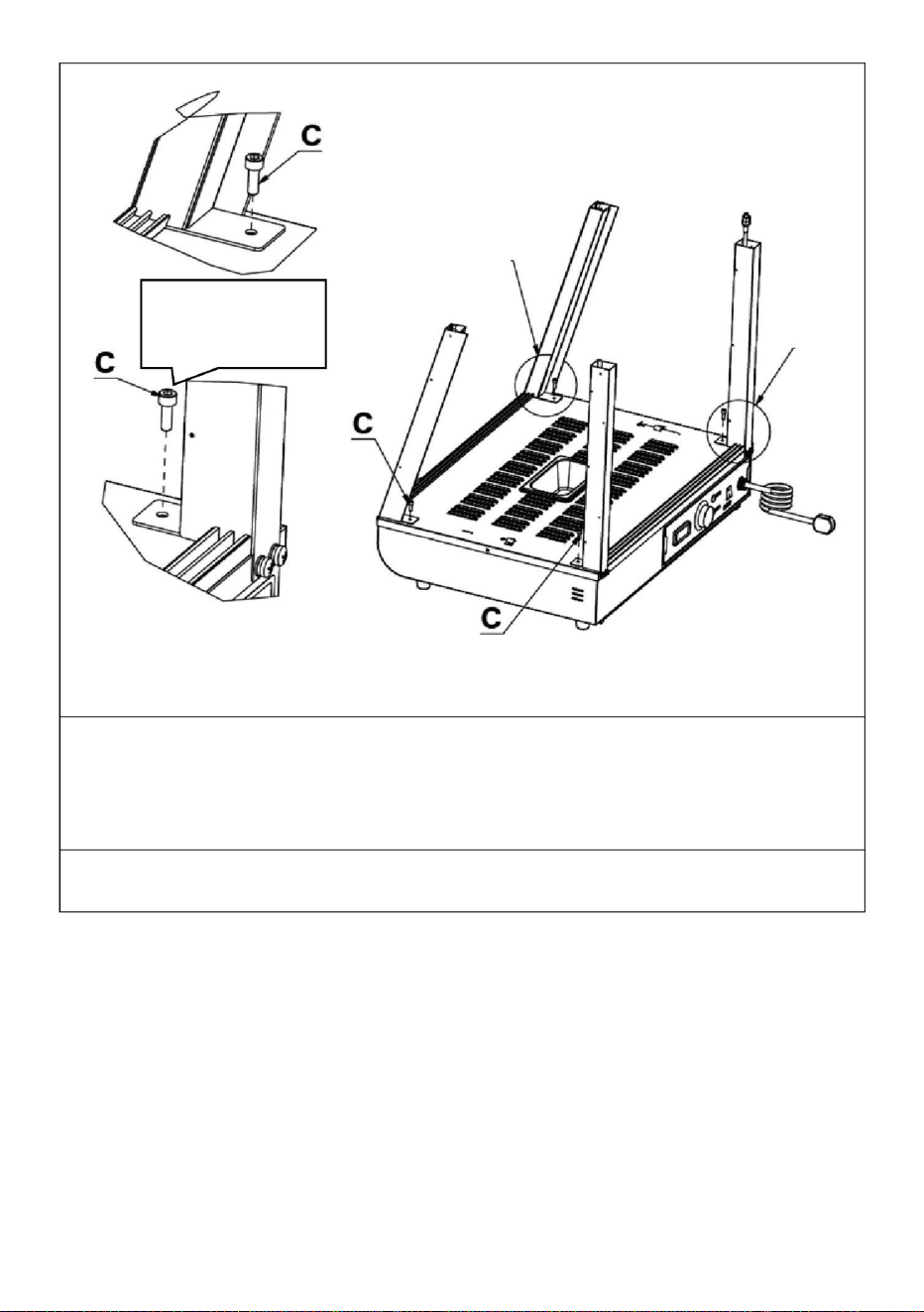
- 14 -
Specifica:
M5*14
Immagine dettagliata B
Passaggio 4
Immagine
B
Dettaglio
Dettaglio immagine A
1.Utilizzare la vite "C" per fissare le quattro colonne ai dadi riservati sulla base
nello stesso modo mostrato nell'immagine dettagliata.
C (4 pezzi)
Machine Translated by Google

1
1
Dettaglio immagine A
Specifica:
1. Collegare il connettore del filo che sporge dal coperchio superiore al connettore
appeso alla colonna e serrarlo, quindi inserire il connettore collegato nella
colonna e nasconderlo.
Dettaglio immagine A
Passaggio 5
M4*8
- 15 -
Machine Translated by Google

1
E (4 PZ)
Nota: La posizione dell'accessorio n. 8 è come mostrato in figura. Il foro grande della zucca
è rivolto verso l'alto, il foro piccolo è rivolto verso il basso e la scanalatura è rivolta verso
l'esterno della macchina!
Passaggio 6
1. Posizionare il coperchio superiore sui quattro montanti verticali, quindi utilizzare le "viti E"
per fissare il coperchio superiore e i montanti verticali (quattro in totale).
1. Allineare i due pilastri del ripiano sinistro e destro "ÿ" nello stesso modo nella
direzione della Figura A, quindi inserirli in diagonale nei fori riservati sulla parte superiore
finché non sono completamente inseriti, quindi allinearli.
ÿ (2 pezzi)
-16-
Machine Translated by Google

Passaggio 7
2. Fare riferimento alla Figura B e allineare la parte inferiore della colonna con il foro riservato nella
piastra di base e posizionarla per completare l'installazione.
1
2
2
- 17 -
Machine Translated by Google

1
2. Quindi, inserire il chiodo della fibbia nella parte posteriore della parte nella bocca della
zucca, come mostrato nell'immagine
qui sotto. ÿ
(3 pezzi) ÿ (3 pezzi)
Passaggio 8
Nota: posizionare la parte sporgente del chiodo a forma di I sulla mensola verso l'esterno
della macchina per l'installazione!
1. Per prima cosa inserire il chiodo del pistone sulla parte anteriore del pezzo nel foro
riservato della colonna come mostrato di seguito.
1. Posizionare le parti "ÿ, ÿ, ÿ" sul supporto dello scaffale secondo le posizioni
mostrate nell'immagine e spingerle nelle fessure riservate come mostrato nell'immagine. ÿ
(1 PZ) ÿ (1 PZ) ÿ (1 PZ)
Passaggio 9 (601 602 603)
- 18 -
Machine Translated by Google

2
1
foto A
1. Per prima cosa, inserire diagonalmente le porte scorrevoli in vetro anteriore e posteriore
nello slot per schede posto in alto, come mostrato nella "Figura A"; dopo averlo inserito
nella posizione estrema, allineare il vetro che cade con lo slot per schede sottostante che
è orizzontale e verticale rispetto allo slot per schede superiore, come mostrato nella "Figura
A". L'installazione è completata come mostrato nella "Figura B". Un totale di quattro
porte scorrevoli in vetro nella parte anteriore e posteriore sono installate allo stesso
modo. ÿ (4 pezzi)
- 19 -
Machine Translated by Google

-20-
Passaggio 9 (anni '60)
1. Installare innanzitutto la cerniera superiore della porta in vetro sulla parte superiore della porta
ribaltabile in vetro e serrare le viti. Quindi preparare la cerniera inferiore della porta
nella posizione corrispondente. Infine, spingere la porta ribaltabile in vetro nella posizione
preparata della cerniera inferiore e quindi serrare le viti della cerniera inferiore!
1. È necessario installare prima il pezzo di vetro interno e poi il pezzo di vetro esterno; 2.
Durante
l'installazione, lo slot per scheda superiore deve essere allineato orizzontalmente e verticalmente
con lo slot per scheda inferiore!
Avviso:
N (Uno per ogni parte superiore e inferiore)
Installare la maniglia della porta prima della porta in vetro (1 PZ)
Machine Translated by Google

- 21 -
N (Uno per ogni parte superiore e inferiore)
Installare la maniglia della porta prima della porta in vetro (1 PZ)
2. Installare innanzitutto la cerniera superiore della porta in vetro sulla parte superiore della porta
ribaltabile in vetro e serrare le viti. Quindi preparare la cerniera inferiore della porta
nella posizione corrispondente. Infine, spingere la porta ribaltabile in vetro nella posizione
preparata della cerniera inferiore e quindi serrare le viti della cerniera inferiore!
Passaggio 10
installazione completata
La posizione delle parti elettriche è progettata in quel momento, l'azienda si riserva
il diritto di modificare il design della valutazione, quando il design cambia e non migliora
il manuale in tempo, spero che i clienti capiscano!
Machine Translated by Google

SC-CJ-60S/SC-CJ-601 Schema elettrico
ST: termostato
Illustrare
SC-CJ-602/SC-CJ-603 Schema elettrico
HL4: Plafoniera
a luce calda 2
HL5: tubo luminoso
a LED
K1: interruttore della luce
Illustrare
HL3: Plafoniera
a luce calda 1
HL1: Potenza
K1: interruttore della luce
HL2: Spia
riscaldamento
spia
spia
HL2: Spia
riscaldamento
HL1: Potenza
Lampada da soffitto
a luce calda HL3
HL4: tubo luminoso
a LED
ST: termostato
FC: tubo riscaldante
FC: tubo riscaldante
10. Schema elettrico
- 22 -
Machine Translated by Google

il controllo della temperatura
è normale
ÿCollegare saldamente il cavo
di alimentazione
Le spie verde e rossa
sono accese
contemporaneamente e la
temperatura non aumenta.
La spia è bruciata
L'isolamento è
C'è una sensazione di
formicolio nel
l'interfaccia non lo è
reparto per la riparazione.
Fusibile dell'interruttore di alimentazione
Guasto del termostato
Guasto del termostato
guscio esterno.
collegato o ha un
contatto scadente.
Metodo di
01
04
esclusione
acceso.
ÿSostituire il
termostato
ÿSostituire il
termostato
mani a causa di perdite
dall'involucro.
06
07
Motivo
ÿSerrare i bulloni del cablaggio
del tubo del riscaldamento
elettrico. ÿSostituire
il tubo del riscaldamento elettrico
il tubo del
riscaldamento è bruciato.
Non può
mantenersi automaticamente
ÿInviarlo alla
manutenzione
La luce non si accende
o tremola.
L'indicatore luminoso
non si accende
quando il dispositivo è acceso
La spia è spenta e il
Caldo.
Il cavo
soffiato
03
05
contatto con il
la luce rimane accesa e
l'aumento della
temperatura non può essere controllato.
NO. Fenomeno di colpa
Il cablaggio del
tubo del
riscaldamento elettrico è
allentato e l'impianto elettrico
L'indicatore del lavoro
ÿSostituire
l'indicatore luminoso
umido o il conduttore
interno è inserito
ÿCollegalo saldamente
ÿSostituire con un
fusibile adatto
02
11. Analisi dei guasti e risoluzione dei problemi:
- 23 -
Machine Translated by Google

REP.CE
REP. DEL REGNO UNITO
Importato negli Stati Uniti: Sanven Technology Ltd. Suite 250, 9166 Anaheim Place,
Rancho Cucamonga, CA 91730
YH CONSULENZA LIMITATA. C/O YH Consulting Limited
Office 147, Centurion House, London Road, Staines-
upon-Thames, Surrey, TW18 4AX
E-CrossStu GmbH
Mainzer Landstr.69,
60329 Francoforte sul Meno.
Produttore: Shanghaimuxinmuyeyouxiangongsi Indirizzo:
Shuangchenglu 803nong11hao1602A-1609shi, baoshanqu, shanghai 200000 CN.
Importato in Australia: SIHAO PTY LTD. 1 ROKEVA STREETEASTWOOD NSW 2122
Australia
Si prega di conservare correttamente questo manuale
Nota: i problemi di cui sopra sono solo per analisi e uso di riferimento. Non affrontarli da
solo. I professionisti competenti sono tenuti a condurre la risoluzione dei problemi e le
riparazioni. In caso di anomalie di sicurezza come perdite, interrompere immediatamente
l'alimentazione e interrompere l'uso!
- 24 -
Machine Translated by Google

Machine Translated by Google


Exhibicióndelcalentadordealimentos
Seguimoscomprometidosaproporcionarleherramientasaprecioscompetitivos.
"Ahorreamitaddeprecio","Amitaddeprecio"ocualquierotraexpresiónsimilarutilizadapornosotrossolo
representaunaestimacióndelosahorrosquepodríabeneficiarsealcomprarciertasherramientasconnosotrosen
comparaciónconlasprincipalesmarcasynosignificanecesariamentecubrirtodaslascategoríasdeherramientas
ofrecidas.pornosotros.Lerecordamosque,cuandorealiceunpedidoconnosotros,verifiquecuidadosamente
sirealmenteestáahorrandolamitadencomparaciónconlasprincipalesmarcas.
SCCJ602/SCCJ603
Modelo:SCCJ60S/SCCJ601/
Soportetécnicoycertificadodegarantíaelectrónicawww.vevor.com/support
Machine Translated by Google

Machine Translated by Google

¿NECESITASAYUDA?¡CONTÁCTENOS!
¿Tienepreguntassobreelproducto?¿Necesitasoportetécnico?Nodudeencontactarnos:
Soporte
técnicoycertificadodegarantíaelectrónicawww.vevor.com/support
SCCJ603
SCCJ601
Estassonlasinstruccionesoriginales;leaatentamentetodaslas
instruccionesdelmanualantesdeoperar.VEVORsereservauna
interpretaciónclaradenuestromanualdeusuario.Laaparienciadel
productoestarásujetaalproductoquerecibió.Perdonequenoleinformaremos
nuevamentesihayactualizacionesdetecnologíaosoftwareennuestroproducto.
MODELO:SCCJ60S/SCCJ601/SCCJ602/SCCJ603
SCCJ602SCCJ60S
Exhibicióndelcalentadordealimentos
1
Machine Translated by Google
cálidorecordatorio
2.Elvoltajeutilizadoporelproductodebeserconsistenteconelvoltajenominal.
Paragarantizarqueesteproductonoserayeduranteeltransporte,secolocaunapelícula
protectoraenlasuperficiedelamáquina.¡Retiretodaslaspelículasprotectorasantesdeusarlas!
Solamenteparausoeninteriores
3.Durantecadauso,agregueaguaalrecipientedeaguahasta2/3delacapacidadantesde
encenderlo.
ELIMINACIÓNCORRECTA
1.Instruccionesdeuso:1.¡El
productodebeestarconectadoatierradeformaseguraantesdesuuso!
EsteproductoestásujetoalodispuestoenlaDirectivaEuropea2012/19/UE.El
símboloquemuestrauncontenedorconruedastachadoindicaqueel
productorequiererecogidaselectivadebasuraenlaUniónEuropea.Estose
aplicaalproductoyatodoslosaccesoriosmarcadosconestesímbolo.Los
productosmarcadoscomotalesnopodrándesecharsejuntoconlabasura
domésticanormal,sinoquedeberánllevarseaunpuntoderecogidaparaelreciclaje
deaparatoseléctricosyelectrónicos.
Advertencia:parareducirelriesgodelesiones,elusuariodebeleer
atentamenteelmanualdeinstrucciones.
4.Enciendalaalimentación,laluzindicadoradealimentaciónestáencendida,gireelinterruptor
decalentamientodecontroldetemperaturayseleccionelatemperaturadeaislamientodelos
alimentosparaaumentarlatemperaturadelespaciodentrodelgabinete.Medianteconvección
natural,latemperaturadecadacapasepuedemantenerconstante.
2
Machine Translated by Google

2.Precaucionesymantenimiento:
3.Noinstalenialmaceneesteequipoenlossiguienteslugares
6.Precaucionesespeciales:
3.3Lugaresconexcesivovolumendeaireyexcesodepolvo.
6.Despuésdeluso,sedebecortarlaenergíadurantelalimpiezaparaevitaraccidentes;
6.2Nosepuededesmontarnimodificar.Desmontarlosin
3.5Dondenoexistaunbuendispositivodepuestaatierra.
profesionalparasolucionarloantesdecontinuarusándolo.
enelusodemaquinariayequipos.
reparadoporunprofesional.Nologolpees.
capacidadesfísicas,sensorialesomentalesreducidasofaltadeexperienciay
enaguaparaevitarfugaseléctricas.
5.Duranteeluso,sinecesitailuminación,puedeencenderelinterruptordeiluminacióndel
9.Dadoquelatemperaturadelequipoesrelativamentealtadurante
Paraevitarunmalfuncionamientodebidoaunmalfuncionamiento:
superficiedelamáquinaparaevitarquemadurasuotraslesiones.
efecto.
3.2Lugaresdondelatemperaturaesdemasiadoaltaodemasiadobaja.
limpielasuperficiedelgabinetedeaislamiento.
6.1Esteproductoesundispositivocomercialynoesadecuadoparausodoméstico.
permisopuedecausaraccidentesgraves.
1.Debeseroperadoporpersonaldesignadoydebesercompetente
7.Siocurrealgunaanomalíaduranteeluso,dejedeusarloysoliciteun
3.4Lugaresdondelatensióndealimentaciónseamuyinestable.
Esteproductonoestádiseñadoparaqueloutilicenpersonas(incluidosniños)con
2.Tengacuidadoalmoverlamáquina.Sihayunafalla,debeser
4.Elaparatonodebelimpiarseconuntuborociadordeaguanisumergirse
5.Estáestrictamenteprohibidoutilizarlíquidossolublesenpinturaparahornearpara
conocimiento.
grupodelucesytodaslaslucesseencenderán,loquepuedemejorarlavisualización
Duranteelfuncionamiento,noacerquelasmanosuotraspartesdelcuerpoal
3.1Sobreunamesaomostradorinestable.
3
Machine Translated by Google

4
6.4Estáprohibidoutilizarobjetosdurosopunzantespararayarelcristal.
5.Descripcióndelossímbolos:
Enestemanual,lossímbolosseutilizanpararesaltartodaslasinstrucciones
yrecomendacionesdeseguridadimportantesrelacionadasconelequipo.Paraevitar
elriesgodeaccidentes,lesionespersonalesodañosalapropiedad,sigaestas
instruccionesconespecialcuidado.
3.Condicionesambientalesdetrabajonormales:1.La
temperaturaambienteesde5a50ylahumedadrelativadelairenosuperael90
%;2.Tensiónde
alimentación:110V±10%,frecuencia:60±1%HZ.(220V±10%,frecuencia:50±1%)
6.3Esnecesariocortarlaenergíaantesdelimpiarparaevitaraccidentesporfugas
accidentales.
4.Introduccióndelproducto:1.
Esteproductotieneundiseñonovedosoyúnico,formadearco,estantederejilla
ajustabledemúltiplescapas,perspectivadevidriodecuatrolados,laparte
superiorutilizaunaplacadePCdealtatransparenciarespetuosaconelmedioambiente
comopaneldeluztransmisoradeluz.YinternamenteseutilizauntuboLEDblancopara
aumentarlavidaútil;Losusuariospuedencolocardiferentestarjetaspublicitarias
segúnsuspropiaspreferenciasparaaumentarlabelleza.Laconveniente
estructuradedesmontajeymontajeesfácildeoperar,resistente,duraderayfácil
demantener.Tieneunatemperaturaconstanteopcionalyunindicadorde
temperatura.Eldiseñodeldownlightdetubocálidosuperiorpuedehacerquela
luzseamásuniformeyestáequipadoconcompensacióndehidrataciónpara
mantenerlosalimentosfrescos.Esunequipoespecialparaexhibicióndealimentosyconservacióndelcalor.
Machine Translated by Google

Frecuencia
120
AC110
240
AC220
240
50
60
SCCJ602
Temperatura
AC220
385*490*640
60
86185F
Voltaje
86185F
AC110
0
Dimensión
(EN)
120
AC110
60
907*470*640
Fuerza
3085
SCCJ603
Modelo
AC220
1.2
50
SCCJ60S
(HZ)
120
1
3085
1210*470*64
rango
50
240
AC220
86185F
1.5
240
3085
1.5
50
SCCJ601
AC110
(MM)
120
86185F
3085
(kilovatios)
60
667*470*640
5
7.Imagendeaparienciadelproducto
SCCJ60S
6.Modelo,especificacionesyprincipalesparámetrostécnicos:
SCCJ601
Machine Translated by Google

8.Diagramadeestructuradelproducto
SCCJ603
SCCJ602
6
Machine Translated by Google

7
Selladodecajaeléctrica
2
Tapasuperiorinferior
1
diseños.Sisecambiaeldiseñoylasinstruccionesnoseactualizanenun
Lacubiertasuperior
4
Base
AluminioenformadeT
Cubiertatranslúcida
1
1
25
1
19
10
No.
Tolvadevidrioinclinada
Imagenespeculardelfrente
13
Columnadeestante
24
02Ranuraparatarjetatranslúcida2
1
01
17
1
Barraguíadelavabode27tiempos
6W
21
1
1
09Cabledeenchufedeaviación
Cant.No.
4
06
23
07
1
1
18
2
bandejadeescoria
Pilardelantero
1
boca
dividir
Cantidad
puerta
Piedemáquinanúmero1
1
22Panelesaislanteslaterales2
pilar
1
28
Pilartrasero
11
lavabode0,5l
05
Listadegráficosdesglosados
1
Correderadevidriofrontal
1
1
15
esemomento.Nuestraempresasereservaelderechodecambiarlosparticipantes.
largo
Vidriolateral
12
Nombre
Tolvadevidriorecta
Cajaelectrica
dieciséis
oportunamente,esperamossucomprensión!
lámina
26
03
Escudotérmicotrasero
04
20
1
1
14
08
lámina
mesabaja
Espejodelpilartrasero
Nombre
apertura
1
manijadelapuerta
Tubodecalefacción
4
tuboLED600mm
Downlightultrafino
2
Nota:Laubicacióndeloscomponenteseléctricossebasaeneldiseñoen
1
Machine Translated by Google

Aplicablealosmodelos:SCCJ601SCCJ602SCCJ603SCCJ60S
8
Inoxidable
lavadora
(8piezas)
M5X14
GRAMO
h
aluminio
(años60ninguno)
(8piezas)
Y
lavadora
Negro
poseedor
M4X12
Listadematerialesdelkitdepiezas
redondonegro
hexágono
(16piezas)
cabezaredonda
pernosdecasquillo
M5
acolchadodeacero
(años60ninguno)
(8PCS)
B
F
tornillos
(4piezas)
empaquetadura
tornillos
Negroplano
D
M4X8
I
tarjetadecristal
(años60ninguno)
Negro
j
acero
M5
Herramientasparatornillos
manejar
(8piezas)
Inoxidable
(8piezas)
(PC1)
M5X14
tornillosdecabeza
A
(8piezas)
Silicona
(4piezas)
C
Primaveranegra
enformadeT
9.Diagramadeinstalacióndelproducto:
Machine Translated by Google

Manejar
Unopara
PC1
Pilardelanteroizquierdo
PC1
PC1
METRO
(PC1)
Exclusivo
Cruzdeacero
cadaparte
superioreinferior
tornillo
accesorio
Nota:Losanterioressontodoslosaccesoriosdelpaquetedeaccesorios.
Pilartraseroizquierdo
Negro
Pilartraseroderecho
Panelde
puertamagnético
Listadepiezasdemontaje
M5X18
(1pieza)
l
Pilardelanteroderecho
60S
Inoxidable
(PC1)
Durantelainstalación,puedeencontrarlostornilloscuyoscódigosenlaimagende
arribacoincidanconloscódigosimpresosenelpaquetedetornillosdeacuerdocon
lostornillosrequeridosenlospasosdeinstalaciónparaunafácilinstalación.
k norte
PC1
Pelota
Juegodebisagrasde
vidrio
9
Machine Translated by Google

10
Estanteinferiormáslargo
3PIEZAS
4PIEZAS
Exclusivo
Columnadeestante
PC1
puertas(años60ninguna)
Estantemediomedio
Vidriolateral
Puertaabatibledevidriofrontal
3PIEZAS
PC1
60S
Estantesuperiormáscorto
2piezas
Correderadecristaldelanteroytrasero
accesorio
Puertadecristaltrasera
2piezas
PC1
Soportedeestanteizquierdo
(cadauno)
Soportedeestantederecho
Machine Translated by Google

11
L(1unidad)
K(1PCS)
Paso1(601602603)
¡Compruebesilosaccesoriosestáncompletosantesdelainstalación!
Paso1(años60)
Nota:Losanterioressontodoslosaccesoriosincluidosenelpaquetedeaccesorios.
M(1PCS)
k
l
G(4PCS)
DiagramadeinstalaciónuniversaldelaserieSCCJ60
DiagramadeinstalaciónuniversaldelaserieSCCJ60
METRO
F(2PCS)
Yo(1Uds.)
Machine Translated by Google

12
Un(4piezas)
3.Imagendetallada
A(1PCS)
(1PCS)
¡instalación!
D(4PCS)
Nota:Alinstalarlascolumnasenamboslados,tengaencuentaqueelladoconorificios
enlacolumnamirahaciaelexteriordelamáquinapara
2.Segúnelordendelaimagen,utilicelostornilloscorrespondientes:"D,A,B"para
bloquearlosaccesorios:","enlosorificiosdetuercareservadosrespectivamente.
1.Paseelconectordelcabledeluzquesobresaledelabaseatravésdelacolumna
ycuélgueloencimadelacolumna.
ImagendetalladaA
E(Especificación:M5*14)
Paso2
B(4PCS)
Machine Translated by Google

13
(1PCS)
(1PCS)
¡instalación!
1.Segúnelordendelaimagen,utilicelostornilloscorrespondientes:"D,A,B"parabloquearlos
accesorios:","enlosorificiosdetuercareservadosrespectivamente.
Un(4piezas)
Especificación
n:M5*14
Nota:Alinstalarlascolumnasenamboslados,tengaencuentaqueelladoconorificiosenla
columnamirahaciaelexteriordelamáquinapara
ImagendetalladaA
ImagendetalladaA
B(4PCS)
D(4PCS)
Paso3
Machine Translated by Google

14
ImagendetalladaB
M5*14
B
delamismamaneraquesemuestraenlaimagendetallada.
imagen
Especificación:
Detalle
ImagendetalladaA
C(4PCS)
Etapa4
1.Utiliceeltornillo“C”parafijarlascuatrocolumnasalastuercasreservadasenlabase.
Machine Translated by Google

1
1
1.Conecteelconectordelcablequesobresaledelacubiertasuperioralconector
quecuelgadelacolumnayapriételo,luegoinserteelconectorconectadoenla
columnayocultelo.
Paso5
ImagendetalladaA
ImagendetalladaA
M4*8
Especificación:
15
Machine Translated by Google

1
Paso6
1.Alineelosdospilaresdelestanteizquierdoyderecho""delamismamaneraen
ladireccióndelaFiguraA,luegoinsértelosdiagonalmenteenlosorificiosreservadosenla
partesuperiorhastaqueesténcompletamenteinsertadosyluegoalinéelos.
E(4PCS)
1.Coloquelacubiertasuperiorenloscuatropostesverticalesyluegouselos"tornillosE"
parafijarlacubiertasuperiorylospostesverticales(cuatroentotal).
(2PCS)
Nota:LaposicióndelaccesorioN°8escomosemuestraenlafigura.¡Elorificiogrande
delorificiodelacalabazaestáhaciaarriba,elorificiopequeñohaciaabajoylaranurahacia
elexteriordelamáquina!
dieciséis
Machine Translated by Google

Paso7
2.ConsultelaFiguraByalineelaparteinferiordelacolumnaconelorificio
reservadoenlaplacabaseycolóquelaparacompletarlainstalación.
1
2
2
17
Machine Translated by Google

1
Nota:ColoquelapartesobresalientedelclavoenformadeIenelsoportedelestantehacia
elexteriordelamáquinaparalainstalación.
Paso9(601602603)
2.Luego,inserteelclavodelahebillaenlaparteposteriordelapiezaenlabocadela
calabazacomosemuestraenla
siguiente
imagen.(3PCS)(3PCS)
1.Primeroinserteelclavodelarieteenlapartefrontaldelapiezaenelorificioreservado
delacolumnacomosemuestraacontinuación.
1.Coloquelaspiezas",,"enelsoportedelestantedeacuerdoconlas
posicionesquesemuestranenlaimagenyempújelasenlasranurasreservadascomose
muestraenlaimagen.
(1PCS)
(1PCS)
(1PCS)
Paso8
18
Machine Translated by Google

1
2
FotoA
1.Primero,insertelaspuertascorredizasdevidriodelanteraytraseraendiagonalenla
ranuraparatarjetasubicadaenlapartesuperior,comosemuestraenla"FiguraA";
Despuésdeinsertarloenlaposiciónextrema,alineeelcristalquecaeconlaranurapara
tarjetasdeabajo,queestáhorizontalyverticalconrespectoalaranuraparatarjetassuperior,
comosemuestraenla"FiguraA".Lainstalaciónsecompletacomosemuestraenla
"FiguraB".Entotalseinstalandelamismamaneracuatropuertascorrederasde
cristaldelanteydetrás.(4PCS)
19
Machine Translated by Google

20
1.Primerodebeinstalarlapiezadevidriointerioryluegolapiezadevidrioexterior;2.Al
instalar,laranura
paratarjetassuperiordebeestaralineadahorizontalyverticalmenteconlaranuraparatarjetas
inferior.
N(Unoparacadapartesuperioreinferior)
Paso9(60S)
Aviso:
Instalelamanijadelapuertaantesdelapuertadevidrio(1unidad).
1.Primeroinstalelabisagrasuperiordelapuertadevidrioenlapartesuperiordelapuerta
abatibledevidrioyaprietelostornillos.Luegopreparelabisagrainferiordelapuerta
enlaposicióncorrespondiente.Finalmente,empujelapuertaabatibledevidrioalaposición
preparadadelabisagrainferiory¡luegoaprietelostornillosdelabisagrainferior!
Machine Translated by Google

21
2.Primeroinstalelabisagrasuperiordelapuertadevidrioenlapartesuperiordelapuerta
abatibledevidrioyaprietelostornillos.Luegopreparelabisagrainferiordelapuerta
enlaposicióncorrespondiente.Finalmente,empujelapuertaabatibledevidrioalaposición
preparadadelabisagrainferiory¡luegoaprietelostornillosdelabisagrainferior!
instalacióncompleta
N(Unoparacadapartesuperioreinferior)
Paso10
Laposicióndelaspiezaseléctricassediseñaenesemomento,laempresasereserva
elderechodecambiareldiseñodelaevaluación,cuandoeldiseñocambiaynomejorael
manualatiempo,¡esperamosquelosclientesloentiendan!
Instalelamanijadelapuertaantesdelapuertadevidrio(1unidad).
Machine Translated by Google

22
10.Diagramadelcircuito
HL1:Poder
Lámparadetecho
deluzcálidaHL3
HL2:Luz
indicadoradecalefacción
HL2:Luz
indicadoradecalefacción
luzindicadora
SCCJ60S/SCCJ601Diagramaesquemáticoeléctrico
ST:Termostato
HL4:Lámparade
techodeluzcálida2
HL5:tubodeluz
LED
FC:tubocalefactor
HL4:tubodeluz
LED
HL3:Lámparade
techodeluzcálida1
Ilustrar
K1:interruptordeluz
ST:Termostato
Ilustrar
SCCJ602/SCCJ603Diagramaesquemáticoeléctrico
FC:tubocalefactor
luzindicadora
K1:interruptordeluz
HL1:Poder
Machine Translated by Google

23
11.Análisisdefallasysolucióndeproblemas:
Razón
Enviarloal
mantenimiento
cálido.
Aprietelospernosdel
cableadodeltubode
calefacción
eléctrica.Reemplaceeltubocalefactoreléctrico
Laluzindicadoraestá
apagadayel
Elcable
Laluznoseenciendeo
parpadea.
encendido.
exclusión
03
05
contactoconel
Reemplacelaluz
indicadora
Fusibledelinterruptordeencendido
Elindicadordetrabajo
húmedooelconductor
interiorestáen
Conéctelofirmemente
Métodode
01
Conecteelcablede
alimentaciónfirmemente
02
Laluzpermaneceencendida
yelaumentode
temperaturanosepuedecontrolar.
Elcontroldetemperaturaes
normal.
Hayunasensaciónde
hormigueoenel
departamentodereparación.
Reemplaceconun
fusibleadecuado
Laslucesindicadoras
verdeyrojaestánencendidas
almismotiempoyla
temperaturanoaumenta.
lainterfaznoes
Luzindicadora
quemada
Elaislamientoes
04
06
conectadootienemal
contacto.
Fallodeltermostato
NO.Fenómenodefalla
Elcableadodel
tubode
calefaccióneléctricaestá
sueltoyelcableeléctrico
Fallodeltermostato
estropeado
Conchaexterior.
manosdebidoafugasdela
carcasa.
Reemplaceel
termostato
Reemplaceel
termostato
07
Eltubocalefactor
estáquemado.
Laluzindicadoranose
enciendecuandoel
dispositivoestá
Nopuede
mantenerautomáticamente
Machine Translated by Google

24
ECrossStuGmbH
YHCONSULTINGLIMITADO.C/OYHConsultingLimited
Oficina147,CenturionHouse,LondonRoad,Stainesupon
Thames,Surrey,TW184AX
ImportadoaAUS:SIHAOPTYLTD.1ROKEVASTREETASTWOODNSW2122Australia
MainzerLandstr.69,
60329FráncfortdelMeno.
Fabricante:ShanghaimuxinmuyeyouxiangongsiDirección:
Shuangchenglu803nong11hao1602A1609shi,baoshanqu,shanghai200000CN.
ImportadoaEE.UU.:SanvenTechnologyLtd.Suite250,9166AnaheimPlace,Rancho
Cucamonga,CA91730
Porfavorconserveestemanualcorrectamente
Nota:Losproblemasanterioressonsóloparaanálisisyusodereferencia.Noseocupede
ellosustedmismo.Serequierenprofesionalesrelevantesparallevaracabolaresolución
deproblemasyreparaciones.Encasodeanomalíasdeseguridad,comofugas,sedebecortar
elsuministrodeenergíainmediatamenteysedebesuspendereluso.
REPRESENTANTEDELREINOUNIDO
REPRESENTANTEDELACE
Machine Translated by Google

Machine Translated by Google


Modelu:SC-CJ-60S/SC-CJ-601/
SC-CJ-602/SC-CJ-603
Wyświetlacz podgrzewacza żywności
Wsparcie techniczne i certyfikat e-gwarancji www.vevor.com/support
„Zaoszczędź o połowę”, „o połowę ceny” lub inne podobne wyrażenia używane przez nas przedstawiają
jedynie szacunkową oszczędność, jaką możesz zyskać kupując u nas określone narzędzia w porównaniu z głównymi
najlepszymi markami i niekoniecznie oznaczają uwzględnienie wszystkich kategorii oferowanych narzędzi przez nas.
Przypominamy, aby podczas składania zamówienia u nas dokładnie sprawdzić, czy rzeczywiście oszczędzasz
połowę w porównaniu z czołowymi markami.
Nadal dokładamy wszelkich starań, aby zapewnić Państwu narzędzia w konkurencyjnej cenie.
Machine Translated by Google

Machine Translated by Google

- 1 -
SC-CJ-602
SC-CJ-603
Masz pytania dotyczące produktu? Potrzebujesz wsparcia technicznego? Prosimy o kontakt:
Wsparcie
techniczne i certyfikat e-gwarancji www.vevor.com/support
To jest oryginalna instrukcja. Przed przystąpieniem do obsługi prosimy o
dokładne zapoznanie się ze wszystkimi instrukcjami. VEVOR zastrzega sobie jasną
interpretację naszej instrukcji obsługi. Wygląd produktu zależy od produktu,
który otrzymałeś. Proszę wybaczyć nam, że nie będziemy ponownie informować
Państwa, jeśli pojawią się jakieś aktualizacje technologii lub oprogramowania naszego produktu.
SC-CJ60S SC-CJ-601
MODEL:SC-CJ-60S/SC-CJ-601/SC-CJ-602/SC-CJ-603
Wyświetlacz podgrzewacza żywności
POTRZEBUJĘ POMOCY? SKONTAKTUJ SIĘ Z NAMI!
Machine Translated by Google

- 2 -
Aby mieć pewność, że produkt nie zostanie zarysowany podczas transportu, na powierzchnię
maszyny naklejona jest folia ochronna. Przed użyciem należy oderwać wszystkie folie ochronne!
1. Instrukcja użytkowania: 1.
Przed użyciem produkt należy bezpiecznie uziemić!
2. Napięcie stosowane przez produkt musi być zgodne z napięciem znamionowym.
3. Przy każdym użyciu przed włączeniem zasilania dolej wody do zbiornika na wodę do 2/3
pojemności.
PRAWIDŁOWA UTYLIZACJA
Do użytku wewnątrz
Ten produkt podlega przepisom Dyrektywy Europejskiej 2012/19/UE. Symbol
przekreślonego kosza na śmieci oznacza, że produkt wymaga
selektywnej zbiórki śmieci na terenie Unii Europejskiej. Dotyczy to produktu
i wszystkich akcesoriów oznaczonych tym symbolem. Produktów oznaczonych
jako takie nie można wyrzucać razem ze zwykłymi odpadami domowymi, lecz
należy je oddać do punktu zbiórki w celu recyklingu urządzeń elektrycznych i
elektronicznych.
Ostrzeżenie — aby zmniejszyć ryzyko obrażeń, użytkownik musi
uważnie przeczytać instrukcję obsługi.
4. Włącz zasilanie, kontrolka zasilania zaświeci się, przekręć przełącznik ogrzewania regulujący
temperaturę i wybierz temperaturę izolacji żywności, aby zwiększyć temperaturę w pomieszczeniu
wewnątrz szafki. Dzięki naturalnej konwekcji temperatura każdej warstwy może być
utrzymywana na stałym poziomie.
Ciepłe przypomnienia
Machine Translated by Google

2. Środki ostrożności i konserwacja:
w użytkowaniu maszyn i urządzeń.
Ten produkt nie jest przeznaczony do użytku przez osoby (w tym dzieci) z
3.5 Tam, gdzie nie ma dobrego urządzenia uziemiającego.
6. Specjalne środki ostrożności:
grupę świateł, a wszystkie światła zostaną włączone, co może poprawić wyświetlanie
obsługi, nie zbliżaj rąk ani innych części ciała do urządzenia
wiedza.
3.3 Miejsca o nadmiernej ilości powietrza i nadmiernym zapyleniu.
6.2 Nie można go demontować ani modyfikować. Demontaż bez
efekt.
powierzchni maszyny, aby uniknąć oparzeń lub innych obrażeń.
aby uniknąć nieprawidłowego działania spowodowanego błędną obsługą:
wytrzyj powierzchnię szafki izolacyjnej.
1. Powinien być obsługiwany przez wyznaczony personel i posiadać odpowiednią wiedzę
naprawiony przez profesjonalistę. Nie pukaj.
w wodzie, aby zapobiec upływowi prądu.
7. Jeśli podczas użytkowania wystąpią jakiekolwiek nieprawidłowości, przestań go używać i zapytaj:
ograniczone możliwości fizyczne, sensoryczne lub umysłowe lub brak doświadczenia i
3.4 Miejsca, w których napięcie zasilania jest bardzo niestabilne.
pozwolenie może spowodować poważne wypadki.
3.2 Miejsca, w których temperatura jest zbyt wysoka lub zbyt niska.
6.1 Ten produkt jest urządzeniem komercyjnym i nie nadaje się do użytku domowego
5. Jeśli podczas użytkowania potrzebujesz oświetlenia, możesz włączyć włącznik oświetlenia
9. Ponieważ temperatura sprzętu jest stosunkowo wysoka podczas
6. Po użyciu należy odciąć zasilanie podczas czyszczenia, aby zapobiec wypadkom;
3. Proszę nie instalować i nie przechowywać tego sprzętu w następujących miejscach
5. Zabrania się stosowania płynów rozpuszczalnych w farbach wypiekowych
3.1 Na niestabilnym stole lub blacie.
2. Zachowaj ostrożność podczas przenoszenia maszyny. Jeśli jest jakiś błąd, to musi tak być
4. Urządzenia nie wolno czyścić rurą natryskową ani zanurzać
profesjonalistę, aby rozwiązał problem przed dalszym użyciem.
- 3 -
Machine Translated by Google

- 4 -
3. Normalne warunki środowiska pracy: 1. Temperatura
otoczenia wynosi 5-50 ℃, a wilgotność względna powietrza nie przekracza 90%; 2.
Napięcie zasilania:
110 V ± 10%, częstotliwość: 60 ± 1% HZ. (220V±10%, częstotliwość: 50±1%)
4. Wprowadzenie produktu: 1.
Ten produkt ma nowatorski i niepowtarzalny design, kształt łuku, wielowarstwową
regulowaną półkę z siatki, czterostronną perspektywę szklaną, na górze
zastosowano przyjazną dla środowiska płytkę drukowaną o wysokiej przezroczystości
jako panel świetlny przepuszczający światło , a biała rura LED jest używana wewnętrznie,
aby zwiększyć żywotność; użytkownicy mogą umieszczać różne karty reklamowe
zgodnie z własnymi preferencjami, aby zwiększyć piękno. Wygodna konstrukcja do
demontażu i montażu jest łatwa w obsłudze, solidna i trwała oraz łatwa w
utrzymaniu. Posiada opcjonalną stałą temperaturę i wyświetlacz temperatury.
Oprawa typu downlight z ciepłą rurką może sprawić, że światło będzie bardziej
jednolite i jest wyposażona w kompensację nawilżania, aby utrzymać świeżość
żywności. Jest to specjalny sprzęt do ekspozycji żywności i utrwalania ciepła.
6.4 Zabrania się używania twardych i ostrych przedmiotów do zarysowania szkła.
6.3 Przed czyszczeniem należy odłączyć zasilanie, aby zapobiec przypadkowym
wyciekom.
5. Opis symboli: W tej instrukcji
symbole służą do podkreślenia wszystkich ważnych instrukcji i zaleceń
dotyczących bezpieczeństwa związanych z urządzeniem. Aby uniknąć ryzyka wypadków,
obrażeń ciała lub szkód materialnych, należy postępować zgodnie z poniższymi
instrukcjami ze szczególną ostrożnością.
Machine Translated by Google

(KW)
60
240
Częstotliwość
240
AC220-
667*470*640
50
30-85 ℃
60
Temperatura
SC-CJ-601
120
240
Napięcie
86-185F
(W)
Wymiar
240
AC220-
50
30-85 ℃
86-185F
86-185F
Model
SC-CJ-60S
120
Moc
1
30-85 ℃
1,5
1210*470*64
1,5
50
(HZ)
AC220-
SC-CJ-603
zakres
60
1.2
907*470*640
50
120
AC110-
30-85 ℃
AC110-
AC110-
AC220-
(MM)
SC-CJ-602
385*490*640
60
0
120
AC110-
86-185F
7. Zdjęcie wyglądu produktu
SC-CJ-60S
6. Model, dane techniczne i główne parametry techniczne:
SC-CJ-601
- 5 -
Machine Translated by Google

8.Schemat struktury produktu
SC-CJ603
SC-CJ-602
- 6 -
Machine Translated by Google

- 7 -
25
26
14 1
Zsyp szkła pochylony
19
10
13
02 Półprzezroczyste gniazdo karty 2
terminowo, liczymy na Państwa zrozumienie!
1
Kolumna półkowa
Uwaga: Rozmieszczenie elementów elektrycznych opiera się na projekcie pod adresem
Górna pokrywa dolna
1
24
Uszczelnienie skrzynki elektrycznej
2
Górna obudowa
Baza
Aluminiowy kształt litery T
Nazwa
1
1
Rozłożona lista wykresów
18
07
1
1
2
filar
usta
przegroda
Przedni słupek
1
drzwi
Taca na żużel
Nazwa
17
ten czas. Nasza firma zastrzega sobie prawo do zmiany uczestniczących
6W
21
1
Prowadnica basenu o 27 skokach
1
1
06
09 Kabel z wtyczką lotniczą
23
4
1
Szyba przednia przesuwana
15
Ilość nr.
1
1
długi
01
Zsyp szklany prosty
Skrzynka elektryczna
Ilość
1
Szkło boczne
22 Boczne panele izolacyjne 2
12
Stopka maszynowa nr 1
1
Tylny słupek
11
28
Zbiornik 0,5L
05
Przezroczysta okładka
otwarcie
Stół bazowy
Lusterko tylne
1
klamka
Tuba LEDowa 600mm
projekty. Jeżeli projekt zostanie zmieniony i instrukcje nie zostaną zaktualizowane w a
Ultracienka oprawa typu downlight
2
Rura grzewcza
1
4
4
16
Lustrzane odbicie przodu
03
płyta
Tylna osłona termiczna
1
1
NIE.
04
20
08
płyta
Machine Translated by Google

Dotyczy modeli: SC-CJ-601, SC-CJ-602, SC-CJ-603, SC-CJ-60S
C
Czarna wiosna
H
Nierdzewny
M5X14
G
W kształcie litery T
aluminium
(4szt)
(lata 60. bez)
I
M5X14
(8szt)(8szt)
Lista materiałów zestawu części
Czarna okrągła
J
okrągła głowa
stal
M5
Nierdzewny Silikon
Narzędzia do śrub
uchwyt
śruby
Czarne mieszkanie
M4X8
B
I
Karta szklana
(lata 60. bez)
8szt
(1 szt.)
D
(4szt)
F
Czarny
wyściełane stalą
uszczelka
(lata 60. bez)
śruby
śruby gniazdowe
M5
(8 SZTUK)
sześciokąt
A
pralka śruby z łbem
(8szt)
Czarny
uchwyt
(16 sztuk)
pralka
(8szt)
M4X12
9. Schemat instalacji produktu:
- 8 -
Machine Translated by Google

Piłka
Zestaw zawiasów do
szkła
Uchwyt
Lewy przedni słupek
1 szt
M
Podczas instalacji możesz znaleźć śruby, których kody na powyższym obrazku
odpowiadają kodom wydrukowanym w opakowaniu śrub, zgodnie ze śrubami
wymaganymi w poszczególnych etapach instalacji, aby ułatwić instalację!
1 szt
Ekskluzywny
Krzyż stalowy
akcesorium
śruba
(1 szt.)
Panel
drzwi magnetyczny
M5X18
(1szt)
Prawy przedni słupek
Czarny
L
Lista części montażowych
Prawy tylny słupek
60S
Nierdzewny
Uwaga: Powyższe są wszystkimi akcesoriami w pakiecie akcesoriów.
Lewy tylny słupek
każdą
górę i dół
K
(1 szt.)
N
1 szt
Jeden dla
1 szt
- 9 -
Machine Translated by Google

- 10 -
Wspornik półki-prawy
Najdłuższa dolna półka
1 szt
Tylne szklane drzwi
Kolumna półkowa
2szt
(po jednym)
Półka średnia-średnia
Przesuwne szyby przednie i tylne
akcesorium
3 SZT
60S
1 szt
Szkło boczne
Przednie szklane drzwi uchylne
Górna półka - najkrótsza
2szt
1 szt
Wspornik półki lewy
Ekskluzywny
drzwi (lata 60- te brak)
3 SZT
4szt
Machine Translated by Google

- 11 -
Schemat instalacji uniwersalnej serii SC-CJ-60
Schemat instalacji uniwersalnej serii SC-CJ-60
L
G (4 SZT.)
F (2 SZT.)
Krok 1(601 602 603)
M
Ja (1 szt.)
K (1 szt.)
L (1 szt.)
Uwaga: Powyższe są wszystkimi akcesoriami zawartymi w pakiecie akcesoriów.
K
M (1 szt.)
Przed instalacją sprawdź, czy akcesoria są kompletne!
Krok 1 (60 s)
Machine Translated by Google

- 12 -
2. Zgodnie z kolejnością na rysunku użyj odpowiednich śrub: „D, A, B”, aby
zablokować akcesoria: „, ” odpowiednio w zarezerwowanych otworach na
nakrętki.
3. Szczegółowy
obraz A
(1 szt.) (1 szt.)
A (4 szt.)
B (4 SZT.)
Uwaga: Podczas instalowania kolumn po obu stronach należy pamiętać, że strona z
otworami w kolumnie skierowana jest na zewnątrz maszyny
instalacja!
1. Przełóż złącze przewodu świetlnego wystające z podstawy przez kolumnę i
zawieś nad kolumną.
Szczegółowy obraz A
Krok 2
E (specyfikacja: M5*14)
D (4 SZT.)
Machine Translated by Google

Uwaga: Podczas instalowania kolumn po obu stronach należy pamiętać, że strona z
otworami w kolumnie skierowana jest na zewnątrz maszyny
instalacja!
(1 szt.)
(1 szt.)
A (4 szt.)
Specyfikacja
nr: M5*14
1. Zgodnie z kolejnością na rysunku użyj odpowiednich śrub: „D, A, B”, aby
zablokować akcesoria: „, ” odpowiednio w zarezerwowanych otworach
na nakrętki.
Szczegółowy obraz A
Szczegółowy obraz A
B (4 SZT.)
Krok 3
D (4 SZT.)
- 13 -
Machine Translated by Google

- 14 -
Specyfikacja:
M5*14
Szczegółowy obraz B
1. Za pomocą śruby „C” przymocuj cztery kolumny do zarezerwowanych nakrętek w podstawie
obraz
B
Szczegół
Szczegółowy obraz A
Krok 4
w taki sam sposób, jak pokazano na szczegółowym obrazku.
C (4 SZT.)
Machine Translated by Google

1
1
Szczegółowy obraz A
Specyfikacja:
1. Podłącz złącze przewodu wystające z górnej pokrywy do złącza wiszącego na
kolumnie i dokręć je, następnie włóż podłączone złącze do kolumny i ukryj je.
Szczegółowy obraz A
Krok 5
M4*8
- 15 -
Machine Translated by Google

1
Krok 6
Uwaga: położenie akcesorium nr 8 pokazano na rysunku. Duży otwór tykwy jest
skierowany do góry, mały otwór jest skierowany w dół, a rowek jest skierowany na
zewnątrz maszyny!
E (4 SZT.)
1. Umieść górną pokrywę na czterech pionowych słupkach, a następnie za pomocą
„śrub E” przymocuj górną pokrywę i pionowe słupki (w sumie cztery).
1. Dopasuj dwa lewe i prawe słupki półki „” w ten sam sposób w kierunku
pokazanym na rysunku A, następnie włóż je po przekątnej w zarezerwowane otwory
na górze, aż zostaną całkowicie wsunięte, a następnie wyrównaj je.
(2 SZTUK)
- 16 -
Machine Translated by Google

2. Zapoznaj się z rysunkiem B i dopasuj dolną część kolumny do
zarezerwowanego otworu w płycie podstawy i umieść ją, aby zakończyć instalację.
Krok 7
1
2
2
- 17 -
Machine Translated by Google

1
Uwaga: Umieść wystającą część gwoździa w kształcie litery I na wsporniku półki w
kierunku zewnętrznej strony urządzenia w celu montażu!
Krok 8
2. Następnie włóż gwóźdź klamry z tyłu części do otworu tykwy, jak pokazano na
poniższym obrazku. (3 SZT.) (3
SZT.)
1. Najpierw włóż gwóźdź tłokowy znajdujący się w przedniej części części w
zarezerwowany otwór w kolumnie, jak pokazano poniżej.
1. Umieść części „, , ” na wsporniku półki zgodnie z pozycjami pokazanymi
na rysunku i wsuń je w zarezerwowane szczeliny, jak pokazano na rysunku. (1 SZT.) (1
SZT.) (1 SZT.)
Krok 9 (601 602 603)
- 18 -
Machine Translated by Google
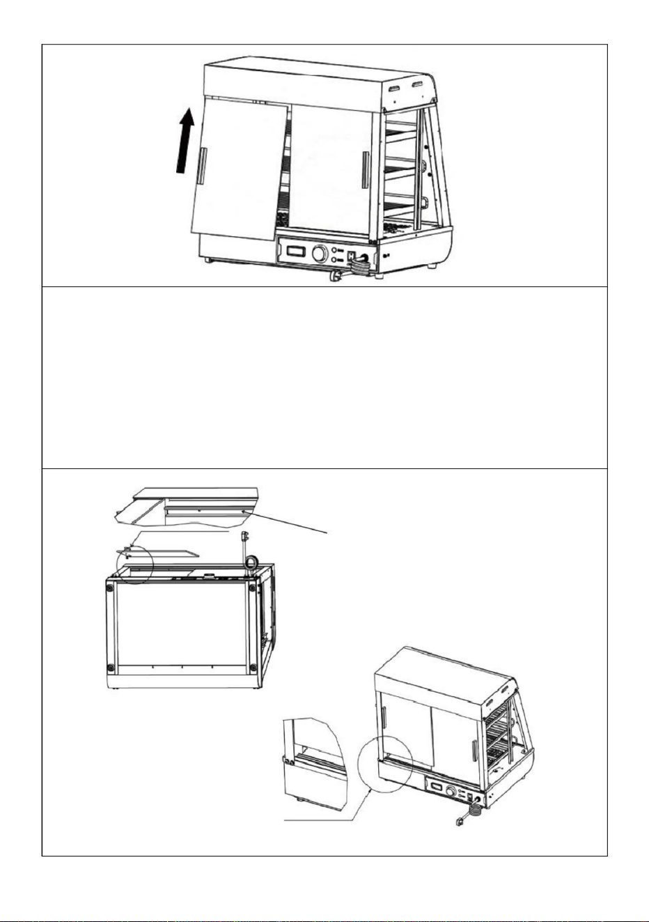
2
1
Zdjęcie A
1. Najpierw włóż przednie i tylne szklane drzwi przesuwne po przekątnej do gniazda karty znajdującego się u góry, jak
pokazano na „Rysunku A”; po włożeniu go do skrajnego położenia, wyrównaj opadające szkło z gniazdem na kartę
poniżej, które jest poziome i pionowe w stosunku do górnego gniazda na kartę, jak pokazano na „Rysunek A”. Instalacja
jest zakończona, jak pokazano na „Rysunku B”. Łącznie cztery szklane drzwi przesuwne z przodu i z tyłu montuje się w ten
sam sposób. (4 SZT.)
- 19 -
Machine Translated by Google
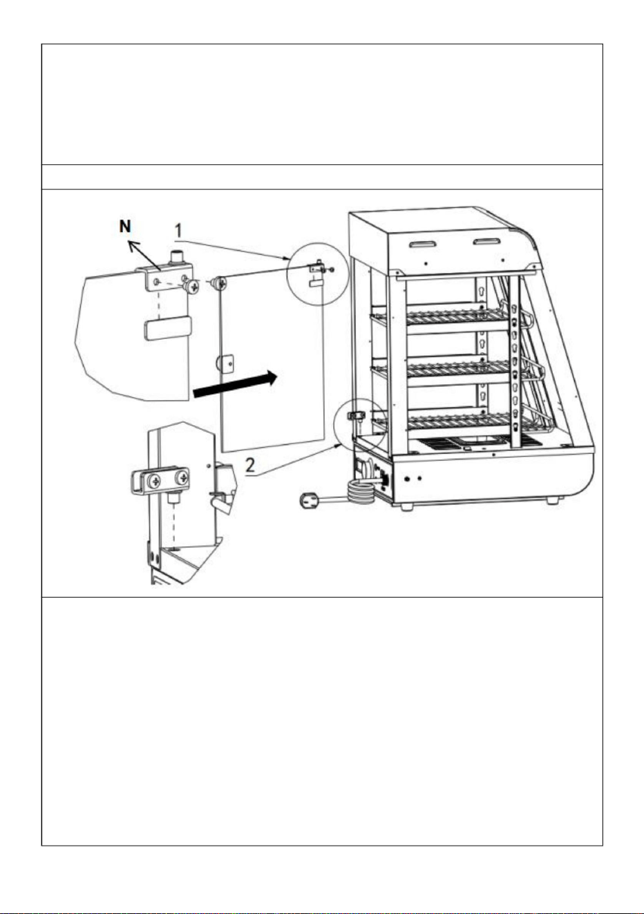
- 20 -
1. Najpierw należy zamontować szybę wewnętrzną, a następnie szybę
zewnętrzną; 2.
Podczas instalacji górne gniazdo karty powinno być wyrównane w poziomie i
pionie z dolnym gniazdem karty!
1. Najpierw zamontuj górny zawias drzwi szklanych na górze szklanych drzwi
uchylnych i dokręć śruby. Następnie przygotuj dolny zawias drzwi
w odpowiedniej pozycji. Na koniec wepchnij szklane drzwi uchylne do
przygotowanej pozycji dolnego zawiasu i następnie dokręć śruby
dolnego zawiasu!
Krok 9 (60 s)
Ogłoszenie:
N (po jednym na górę i na dół)
Zainstaluj klamkę przed szklanymi drzwiami (1 szt.)
Machine Translated by Google

N (po jednym na górę i na dół)
Zainstaluj klamkę przed szklanymi drzwiami (1 szt.)
2. Najpierw zamontuj górny zawias drzwi szklanych na górze szklanych drzwi
uchylnych i dokręć śruby. Następnie przygotuj dolny zawias drzwi
w odpowiedniej pozycji. Na koniec wepchnij szklane drzwi uchylne do
przygotowanej pozycji dolnego zawiasu i następnie dokręć śruby
dolnego zawiasu!
Krok 10
instalacja zakończona
Położenie części elektrycznych jest projektowane w tym czasie, firma
zastrzega sobie prawo do zmiany projektu oceny, gdy projekt ulegnie
zmianie i nie poprawi instrukcji na czas, mam nadzieję, że klienci zrozumieją!
- 21 -
Machine Translated by Google

- 22 -
10. Schemat obwodu
SC-CJ-602/SC-CJ-603 Schemat elektryczny
Zilustrować
HL4: Lampa sufitowa
o ciepłym świetle 2
HL5: świetlówka
LED
HL3: Lampa sufitowa
o ciepłym świetle 1
K1: Włącznik światła
Zilustrować
FC: rura grzewcza
K1: Włącznik światła
HL1: Moc
HL2: Lampka
kontrolna ogrzewania
Kontrolka
Kontrolka
HL1: Moc
HL2: Lampka
kontrolna ogrzewania
Lampa sufitowa HL3
o ciepłym świetle
FC: rura grzewcza
HL4: świetlówka
LED
SC-CJ-60S/SC-CJ-601 Schemat elektryczny
ST: Termostat
ST: Termostat
Machine Translated by Google

- 23 -
11. Analiza usterek i rozwiązywanie problemów:
Zielona i czerwona
kontrolka świecą się
jednocześnie, a
temperatura nie wzrasta.
interfejs nie
Podłącz mocno
przewód zasilający
Przepaliła się
kontrolka
04
Metoda
01
Izolacja jest
06
Bezpiecznik wyłącznika zasilania
Awaria termostatu
Awaria termostatu
powłoka zewnętrzna.
podłączony lub ma
słaby kontakt.
wykluczenie
włączone.
Wymień
termostat
Wymień
termostat
ręce z powodu wycieku z
obudowy.
07
Dokręć śruby okablowania
rur ogrzewania
elektrycznego.
Wymień elektryczną rurkę grzejną
przepalona rura
grzewcza.
Nie może
automatycznie zachować
Powód
Wyślij go do
serwisu
Światło nie świeci się lub
nie miga.
Lampka kontrolna nie
świeci się, gdy
urządzenie jest włączone
Lampka kontrolna
zgaśnie i
ciepły.
Kabel
03
05
nadęty
kontakt z
NIE. Zjawisko usterki
Wskaźnik pracy
Okablowanie
elektrycznej
rury grzewczej jest
luźne i elektryczne
Wymień lampkę
kontrolną
wilgotny lub przewód
wewnętrzny jest w środku
Podłącz go mocno
lampka pozostaje włączona
i nie można
kontrolować wzrostu temperatury.
02
kontrola temperatury jest
normalna
Wymień na
odpowiedni bezpiecznik
Występuje uczucie
mrowienia w
dział naprawy.
Machine Translated by Google

- 24 -
Import do USA: Sanven Technology Ltd. Suite 250, 9166 Anaheim Place, Rancho
Cucamonga, CA 91730
YH CONSULTING SPÓŁKA Z OGRANICZONĄ
ODPOWIEDZIALNOŚCIĄ. C/O YH Consulting Limited
Office 147, Centurion House, London Road, Staines-upon-Thames, Surrey, TW18 4AX
E-CrossStu GmbH
Mainzer Landstr.69,
60329 Frankfurt nad Menem.
Producent: Shanghaimuxinmuyeyouxiangongsi Adres:
Shuangchenglu 803nong11hao1602A-1609shi, baoshanqu, szanghaj 200000 CN.
Import do AUS: SIHAO PTY LTD. 1 ROKEVA STREETEASTWOOD NSW 2122 Australia
Prosimy o prawidłowe przechowywanie niniejszej instrukcji
Uwaga: Powyższe problemy służą wyłącznie celom analitycznym i referencyjnym. Nie
zajmuj się nimi sam. Do rozwiązywania problemów i napraw potrzebni są odpowiedni
specjaliści. W przypadku wystąpienia nieprawidłowości związanych z bezpieczeństwem,
takich jak wyciek, należy natychmiast odłączyć zasilanie i zaprzestać użytkowania!
REPREZENT KE
REPUBLIKA Wielkiej Brytanii
Machine Translated by Google

Machine Translated by Google


Voedselverwarmer-display
"Bespaar de helft", "Halve prijs" of andere soortgelijke uitdrukkingen die door ons worden gebruikt vertegenwoordigt
slechts een schatting van de besparingen die u zou kunnen profiteren als u bepaalde gereedschappen bij ons koopt in
vergelijking met de grote topmerken en betekent niet noodzakelijkerwijs dat deze alle categorieën van aangeboden
gereedschappen omvatten door ons. Wij verzoeken u vriendelijk om bij het plaatsen van een bestelling bij ons
goed na te gaan of u daadwerkelijk de helft bespaart in vergelijking met de grote topmerken.
We blijven ons inzetten om u gereedschap tegen een concurrerende prijs te bieden.
Model: SC-CJ-60S/SC-CJ-601/
SC-CJ-602/SC-CJ-603
Technische ondersteuning en e-garantiecertificaat www.vevor.com/support
Machine Translated by Google

Machine Translated by Google
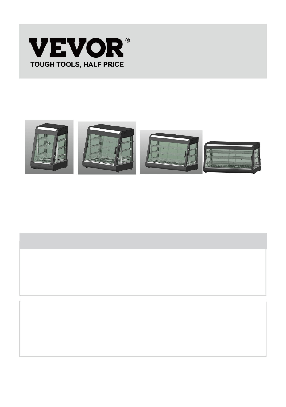
- 1 -
Heeft u productvragen? Technische ondersteuning nodig? Neem gerust contact met ons op:
Technische
ondersteuning en e-garantiecertificaat www.vevor.com/
support
SC-CJ-603
SC-CJ-601
Dit is de originele instructie. Lees alle instructies in de handleiding zorgvuldig
door voordat u ermee aan de slag gaat. VEVOR behoudt zich een duidelijke interpretatie
van onze gebruikershandleiding voor. Het uiterlijk van het product is afhankelijk
van het product dat u heeft ontvangen. Vergeef ons alstublieft dat we u niet opnieuw
zullen informeren als er technologie- of software-updates zijn voor ons product.
MODEL: SC-CJ-60S/SC-CJ-601/SC-CJ-602/SC-CJ-603
SC-CJ-602SC-CJ60S
Voedselverwarmer-display
HULP NODIG? NEEM CONTACT MET ONS OP!
Machine Translated by Google

- 2 -
2. De door het product gebruikte spanning moet consistent zijn met de nominale spanning.
Om ervoor te zorgen dat dit product tijdens het transport geen krassen oploopt, is er een
beschermfolie op het oppervlak van de machine aangebracht. Scheur vóór gebruik alle
beschermfolies af!
Alleen binnenshuis te gebruiken
3. Voeg tijdens elk gebruik water toe aan het waterbassin tot 2/3 van de capaciteit voordat u
de stroom inschakelt.
CORRECTE VERWIJDERING
1. Gebruiksaanwijzing: 1. Het
product moet voor gebruik veilig geaard zijn!
Dit product valt onder de bepalingen van de Europese Richtlijn 2012/19/EU. Het
symbool met een doorgestreepte afvalcontainer geeft aan dat het product
in de Europese Unie een aparte afvalinzameling vereist. Dit geldt voor het
product en alle accessoires die met dit symbool zijn gemarkeerd. Producten die
als zodanig gemarkeerd zijn, mogen niet met het normale huisvuil worden
weggegooid, maar moeten naar een inzamelpunt voor recycling van elektrische en
elektronische apparaten worden gebracht.
Waarschuwing-Om het risico op letsel te verminderen, moet de
gebruiker de handleiding zorgvuldig lezen.
4. Schakel de stroom in, het stroomindicatielampje brandt, draai de verwarmingsschakelaar voor
de temperatuurregeling en selecteer de isolatietemperatuur van het voedsel om de temperatuur
van de ruimte in de kast te verhogen. Door natuurlijke convectie kan de temperatuur van elke
laag consistent worden gehouden.
Warme herinnering
Machine Translated by Google

2. Voorzorgsmaatregelen en onderhoud:
6. Na gebruik moet de stroom worden uitgeschakeld tijdens het reinigen om ongelukken te voorkomen;
kennis.
3. Installeer en bewaar deze apparatuur niet op de volgende locaties
5. Het is ten strengste verboden om vloeistoffen te gebruiken die oplosbaar zijn in bakverf
6.2 Het kan niet worden gedemonteerd of aangepast. Demonteren zonder
tijdens de bediening, breng uw handen of andere lichaamsdelen niet in de buurt van de
lichtgroep en alle lichten worden ingeschakeld, wat de weergave kan verbeteren
Dit product is niet bedoeld voor gebruik door personen (inclusief kinderen) met
2. Wees voorzichtig bij het verplaatsen van de machine. Als er sprake is van een fout, dan moet dat zo zijn
3.1 Op een onstabiele tafel of toonbank.
4. Het apparaat mag niet worden gereinigd met een watersproeipijp of worden ondergedompeld
7. Als er tijdens het gebruik iets abnormaals optreedt, stop dan met het gebruik en vraag a
toestemming kan ernstige ongelukken veroorzaken.
1. Het moet worden bediend door aangewezen personeel en moet bekwaam zijn
3.4 Plaatsen waar de voedingsspanning zeer onstabiel is.
oppervlak van de machine om brandwonden of ander letsel te voorkomen.
effect.
3.2 Plaatsen waar de temperatuur te hoog of te laag is.
6.1 Dit product is een commercieel apparaat en is niet geschikt voor thuisgebruik
5. Als u tijdens gebruik verlichting nodig heeft, kunt u de verlichtingsschakelaar van de verlichting inschakelen
9. Omdat de temperatuur van de apparatuur relatief hoog is tijdens
om defecten als gevolg van een verkeerde bediening te voorkomen:
veeg het oppervlak van de isolatiekast schoon.
gerepareerd door een professional. Klop er niet op.
verminderde fysieke, zintuiglijke of mentale vermogens of gebrek aan ervaring en
in water om elektrische lekkage te voorkomen.
professional om problemen op te lossen voordat u het apparaat verder gebruikt.
bij het gebruik van machines en apparatuur.
3.5 Waar er geen goed aardingsapparaat is.
6. Speciale voorzorgsmaatregelen:
3.3 Plaatsen met een overmatig luchtvolume en overmatig stof.
- 3 -
Machine Translated by Google

3. Normale werkomgevingsomstandigheden: 1. De
omgevingstemperatuur is 5-50 ÿ en de relatieve luchtvochtigheid is niet meer dan 90%; 2.
Voedingsspanning:
110V ± 10%, frequentie: 60 ± 1% Hz. (220V±10%, frequentie: 50±1%)
5. Beschrijving van symbolen: In
deze handleiding worden symbolen gebruikt om alle belangrijke veiligheidsinstructies en
aanbevelingen met betrekking tot de apparatuur te benadrukken. Om het risico op ongelukken, persoonlijk
letsel of materiële schade te voorkomen, dient u deze instructies met bijzondere zorg op te
volgen.
6.4 Het is verboden harde of scherpe voorwerpen te gebruiken om krassen op het glas te maken.
6.3 De stroom moet vóór het reinigen worden uitgeschakeld om onbedoelde lekkage-ongelukken te
voorkomen.
4. Productintroductie: 1. Dit product
heeft een nieuw en uniek ontwerp, boogvorm, meerlaags verstelbare roosterplank, vierzijdig
glasperspectief, de bovenkant maakt gebruik van een milieuvriendelijke, hoogtransparante pc-
plaat als lichtdoorlatend lichtpaneel en intern wordt een witte LED-buis gebruikt om de levensduur te
verlengen; gebruikers kunnen verschillende reclamekaarten plaatsen volgens uw eigen voorkeuren om de
schoonheid te vergroten. De handige demontage- en montagestructuur is eenvoudig te bedienen,
stevig en duurzaam en gemakkelijk te onderhouden. Het beschikt optioneel over een constante
temperatuur en een temperatuurdisplay. Het ontwerp van de bovenste warme buis-downlight kan het
licht uniformer maken en is uitgerust met vochtcompensatie om het voedsel vers te houden. Het is
een speciale uitrusting voor het tentoonstellen van voedsel en het behoud van warmte.
- 4 -
Machine Translated by Google

7. Afbeelding van het uiterlijk van het product
- 5 -
AC110-
Temperatuur
AC220-
(MM)
SC-CJ-602
120
Spanning
86-185F
Frequentie
120
AC110-
AC110-
240
385*490*640
86-185F
50
Stroom
60
SC-CJ-603
Model
AC220-
1.2
50
86-185F
0
Dimensie
(IN)
120
AC110-
60
907*470*640
30-85ÿ
bereik
50
240
AC220-
86-185F
1.5
SC-CJ-60S
(HZ)
120
1
30-85ÿ
30-85ÿ
1210*470*64
(kW)
60
667*470*640
240
AC220-
240
30-85ÿ
1.5
60
50
SC-CJ-601
SC-CJ-60S
6. Model, specificaties en belangrijkste technische parameters:
SC-CJ-601
Machine Translated by Google

- 6 -
SC-CJ603
SC-CJ-602
8.Productstructuurdiagram
Machine Translated by Google

Afdichting van elektrische kasten
2
Bovenklep onderkant
1
ontwerpen. Als het ontwerp wordt gewijzigd en de instructies niet worden bijgewerkt in a
Bovenklep
4
Baseren
Aluminium T-vormig
Doorschijnende hoes
1
1
25
1
19
10
Nee.
Glazen goot schuin
Spiegelbeeld voorkant
13
Plankkolom
24
02 Doorzichtige kaartsleuf 2
1
01
17
1
27 Slag wastafelgeleider
6W
21
1
1
09 Luchtvaartstekkerkabel
Aantal nr.
4
06
23
07
1
1
18
2
Slakkenbak
Voorste pijler
1
mond
partitie
Aantal
deur
Nr. 1 machinevoet
1
22 Zij-isolatiepanelen 2
pijler
1
28
Achterste pijler
11
Bassin van 0,5 liter
05
Geëxplodeerde kaartlijst
1
Glazen schuifpui vooraan
1
1
15
die tijd. Ons bedrijf behoudt zich het recht voor om de deelname te wijzigen
lang
Zijglas
12
Naam
Glazen goot recht
tijdig, wij hopen op uw begrip!
bord
Elektrische kast
16
26
03
Hitteschild achteraan
04
20
1
1
14
08
bord
Basis tafel
Spiegel in de achterstijl
Naam
opening
1
deurklink
Verwarming pijp
4
LED buis 600mm
Ultradunne downlight
2
Let op: De locatie van de elektrische componenten is gebaseerd op het ontwerp bij
1
- 7 -
Machine Translated by Google

A EN
wasmachine kop schroeven
(8 stuks)(8 stuks)
Onderdelenset stuklijst
Zwart rond
Roestvrij
wasmachine
zeshoek
(8 stuks)
H
Zwart
Siliconen
aluminium
B
houder
F
schroeven
(4 stuks)
pakking
schroeven
M4X12
(16 stuks)
rond hoofd
inbusbouten
M5
staal gevoerd
(Jaren 60 geen)
(8 STUKS)
Zwart
J
staal
M5
Gereedschap voor schroeven
(8 stuks)
Zwart plat
D
M4X8
I
Glazen kaart
(4 stuks)
(Jaren 60 geen)
C
Zwarte veer
T-vormig
M5X14
G
(8 stuks)
Roestvrij
hendel
(Jaren 60 geen)
(1 stuk)
M5X14
- 8 -
Van toepassing op modellen: SC-CJ-601, SC-CJ-602, SC-CJ-603, SC-CJ-60S
9.Productinstallatieschema:
Machine Translated by Google

K M N
(1 stuk)
1 STUK
1 STUK
Stalen kruis
Exclusief
Hendel
Een voor
elke boven-
en onderkant
1 STUK
ÿ
Zwart
Rechter achterstijl
Deurpaneel
met magneet
Lijst met montageonderdelen
schroef
accessoire
Let op: Bovenstaande zijn alle accessoires in het accessoirepakket.
Linker achterstijl
Jaren 60
Roestvrij
(1 stuk)
ÿ
M5X18
(1 stuks)
L
Rechtervoorstijl
ÿ
Bal
Glazen
scharnierset
Linker voorstijl
1 STUK
ÿ
Tijdens de installatie kunt u de schroeven vinden waarvan de codes op de afbeelding
hierboven overeenkomen met de codes die in de schroevenverpakking zijn afgedrukt,
volgens de schroeven die vereist zijn in de installatiestappen voor eenvoudige installatie!
- 9 -
Machine Translated by Google

- 10 -
1 STUK
Plankkolom
Plankbeugel-links
ÿ
Exclusief
(elk een)
ÿ
1 STUK
Lagere plank-langste
3 STUKS
deuren (jaren 60 geen)
4 STUKS
ÿ
3 STUKS
ÿ
ÿ
Middelste plank-medium
Zijglas
ÿ Glazen klapdeur aan de voorkant
Bovenste plank - kortste
2 STUKS
Glazen schuifpui voor en achter
accessoire
ÿ
1 STUK
Jaren 60
ÿ
Plankbeugel-rechts
ÿ
ÿGlazen deur achteraan
2 STUKS
Machine Translated by Google

- 11 -
ÿ
L (1 STUKS)
K (1 STUKS)
Stap 1(601 602 603)
Stap 1 (jaren 60)
Controleer vóór installatie of de accessoires compleet zijn!
Let op: Bovenstaande zijn alle accessoires die in het accessoirepakket zitten.
M (1 STUKS)
K
L
G (4 STUKS)
SC-CJ-60-serie universeel installatieschema
SC-CJ-60-serie universeel installatieschema
M
F (2 STUKS)
ik (1 STUKS)
Machine Translated by Google

- 12 -
EEN (4 STUKS)
3. Detailafbeelding A
ÿ (1 STUKS)
ÿ (1 STUKS)
installatie!
Stap 2
Opmerking: Houd er bij het installeren van de kolommen aan beide zijden rekening mee dat
de kant met gaten in de kolom naar de buitenkant van de machine is gericht.
2. Gebruik volgens de volgorde van de afbeelding de bijbehorende schroeven: "D, A, B" om de
accessoires te vergrendelen: "ÿ, ÿ" respectievelijk op de gereserveerde moergaten.
1. Leid de lichtsnoerconnector die uit de basis steekt door de kolom en hang deze boven de
kolom.
Detailafbeelding A
B (4 STUKS)
D (4 STUKS)
E (Specificatie: M5*14)
Machine Translated by Google

- 13 -
ÿ(1 STUKS)
ÿ(1 STUKS)
installatie!
1. Gebruik volgens de volgorde van de afbeelding de bijbehorende schroeven: "D, A, B" om de
accessoires te vergrendelen: "ÿ, ÿ" respectievelijk op de gereserveerde moergaten.
Stap 3
Detailafbeelding A
Opmerking: Houd er bij het installeren van de kolommen aan beide zijden rekening mee dat de
kant met gaten in de kolom naar de buitenkant van de machine is gericht.
Specificatie nr.:
M5*14
Detailafbeelding A
EEN (4 STUKS)
B (4 STUKS)
D (4 STUKS)
Machine Translated by Google

- 14 -
Detailafbeelding B
M5*14
B
op dezelfde manier als weergegeven in de gedetailleerde afbeelding.
afbeelding
Specificatie:
Detail
Detailafbeelding A
C (4 STUKS)
Stap 4
1. Gebruik schroef “C” om de vier kolommen aan de gereserveerde moeren op de basis te bevestigen
Machine Translated by Google

1
1
Detailafbeelding A
Stap 5
1. Sluit de draadconnector die uit de bovenklep steekt aan op de connector die aan
de kolom hangt en draai deze vast. Steek vervolgens de aangesloten connector
in de kolom en verberg deze.
Detailafbeelding A
M4*8
Specificatie:
- 15 -
Machine Translated by Google

1
Stap 6
1. Lijn de twee linker en rechter plankstijlen "ÿ" op dezelfde manier uit in de richting van
Afbeelding A, steek ze vervolgens diagonaal in de gereserveerde gaten aan de bovenkant totdat
ze volledig zijn ingebracht, en lijn ze vervolgens uit.
E (4 STUKS)
1. Plaats het bovendeksel op de vier rechtopstaande palen en gebruik vervolgens "schroeven E"
om het bovendeksel en de rechtopstaande palen vast te zetten (vier in totaal).
ÿ (2 STUKS)
Opmerking: De positie van accessoire nr. 8 is zoals weergegeven in de afbeelding. Het grote gat
van het kalebasgat is naar boven gericht, het kleine gat is naar beneden gericht en de groef is naar
de buitenkant van de machine gericht!
- 16 -
Machine Translated by Google

Stap 7
2. Zie afbeelding B, lijn de onderkant van de kolom uit met het gereserveerde
gat in de basisplaat en plaats deze om de installatie te voltooien.
1
2
2
- 17 -
Machine Translated by Google
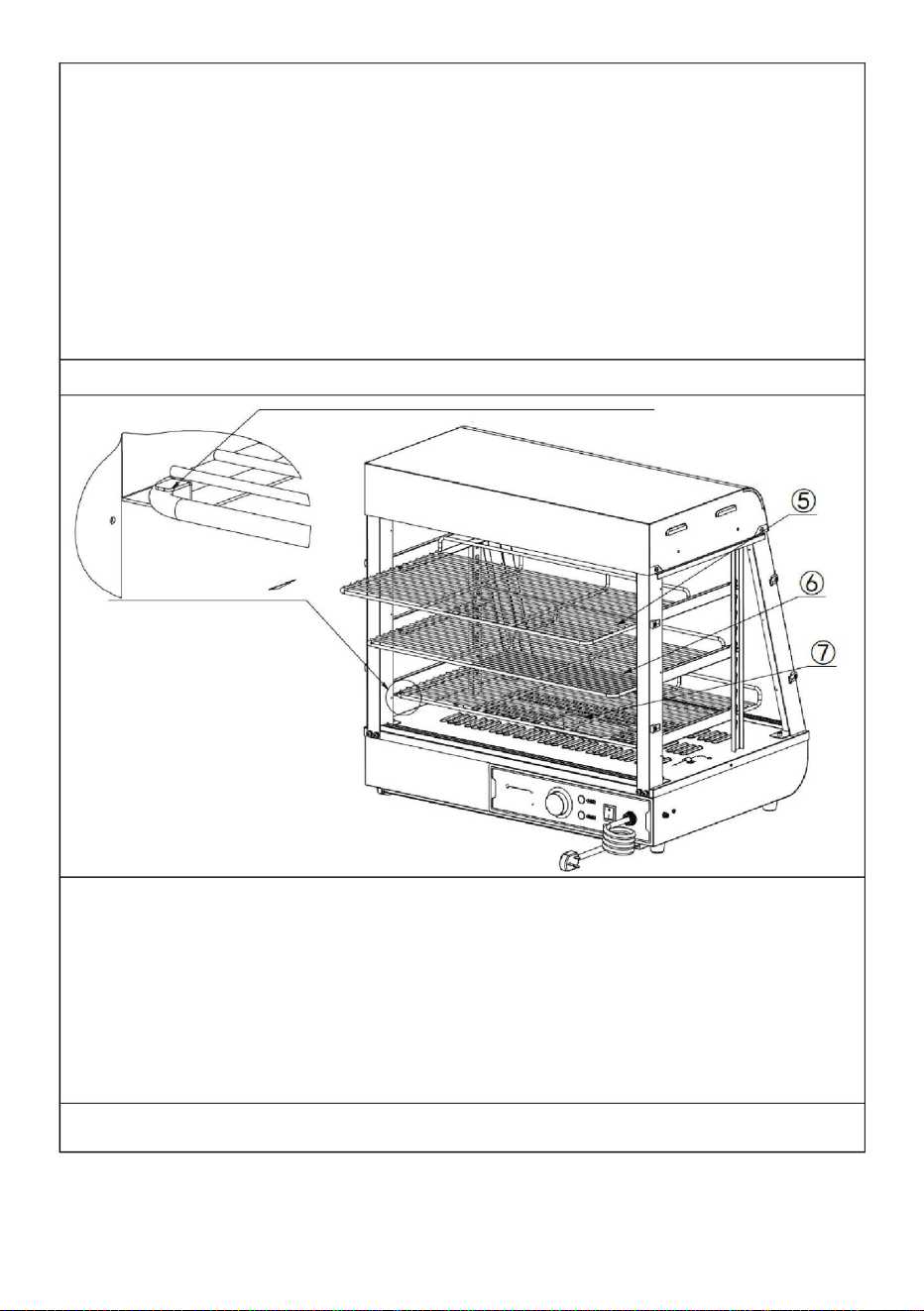
1
Let op: Plaats het uitstekende deel van de I-vormige spijker op de plankbeugel richting de
buitenkant van de machine voor installatie!
Stap 9 (601 602 603)
2. Steek vervolgens de gespspijker aan de achterkant van het onderdeel in de kalebasmond, zoals
weergegeven in de onderstaande
afbeelding. ÿ
(3 STUKS) ÿ (3 STUKS)
1. Steek eerst de ramspijker op het voorste deel van het onderdeel in het daarvoor bestemde
gat van de kolom, zoals hieronder weergegeven.
1. Plaats de onderdelen "ÿ, ÿ, ÿ" op de plankbeugel volgens de posities weergegeven in
de afbeelding, en druk ze in de gereserveerde sleuven zoals weergegeven in de afbeelding. ÿ
(1 STUKS) ÿ (1 STUKS) ÿ
(1 STUKS)
Stap 8
- 18 -
Machine Translated by Google

2
1
Foto A
1. Plaats eerst de glazen schuifdeuren aan de voor- en achterzijde diagonaal in de
kaartsleuf bovenaan, zoals weergegeven in "Figuur A"; Nadat u het in de uiterste positie
hebt geplaatst, lijnt u het vallende glas uit met de kaartsleuf eronder, die horizontaal en
verticaal is ten opzichte van de bovenste kaartsleuf, zoals weergegeven in "Afbeelding A".
De installatie is voltooid zoals weergegeven in "Figuur B". Op dezelfde wijze worden in
totaal vier glazen schuifdeuren aan de voor- en achterzijde gemonteerd. ÿ (4
STUKS)
- 19 -
Machine Translated by Google

- 20 -
Stap 9 (60S)
N(Eén voor elke boven- en onderkant)
1. U moet eerst het binnenste stuk glas installeren en vervolgens het buitenste stuk
glas; 2. Bij
installatie moet de bovenste kaartsleuf horizontaal en verticaal uitgelijnd zijn met de onderste
kaartsleuf!
Kennisgeving:
Installeer de deurklink vóór de glazen deur (1 STKS)
1. Installeer eerst het bovenste glazen deurscharnier op de bovenkant van de glazen klapdeur
en draai de schroeven vast. Bereid vervolgens het onderste deurscharnier in de
overeenkomstige positie voor. Duw ten slotte de glazen klapdeur in de voorbereide positie
van het onderste scharnier en draai vervolgens de schroeven van het onderste
scharnier vast!
Machine Translated by Google

- 21 -
N(Eén voor elke boven- en onderkant)
Installatie voltooid
2. Installeer eerst het bovenste scharnier van de glazen deur op de bovenkant van de glazen
klapdeur en draai de schroeven vast. Bereid vervolgens het onderste deurscharnier
in de overeenkomstige positie voor. Duw ten slotte de glazen klapdeur in de voorbereide
positie van het onderste scharnier en draai vervolgens de schroeven van het onderste
scharnier vast!
Stap 10
De positie van de elektrische onderdelen is op dat moment ontworpen, het
bedrijf behoudt zich het recht voor om het ontwerp van de evaluatie te wijzigen,
wanneer het ontwerp verandert en de handleiding niet op tijd verbetert, hoop dat
klanten het begrijpen!
Installeer de deurklink vóór de glazen deur (1 STKS)
Machine Translated by Google

HL1: Kracht
HL3 warmlicht
plafondlamp
HL2:
Controlelampje verwarming
HL2:
Controlelampje verwarming
indicatielampje
SC-CJ-60S/SC-CJ-601 Elektrisch schema
ST: Thermostaat
HL4:
Warmlichtplafondlamp 2
HL5: LED-lichtbuis
FC: verwarmingsbuis
HL4: LED-lichtbuis
HL3:
Warmlichtplafondlamp 1
K1: Lichtschakelaar
Illustreren
ST: Thermostaat
Illustreren
SC-CJ-602/SC-CJ-603 Elektrisch schema
FC: verwarmingsbuis
indicatielampje
K1: Lichtschakelaar
HL1: Kracht
10. Schakelschema
- 22 -
Machine Translated by Google

De bedrading
van de elektrische
verwarmingsbuis is los
en de elektrische
Zekering stroomschakelaar
De werkindicator
NEE. Fout fenomeen
ÿVervang het
indicatielampje
Thermostaat defect
Methode van
01
ÿSteek het netsnoer stevig in
het stopcontact
02
het licht blijft branden en de
temperatuurstijging
kan niet worden gecontroleerd.
temperatuurregeling is
normaal
Er is een tintelend
gevoel in de
vochtig of de
binnengeleider zit erin
buitenschaal.
afdeling voor reparatie.
Reden
ÿSluit hem stevig aan
warm.
ÿZet de bedradingsbouten
van de elektrische
verwarmingsbuis
vast. ÿVervang de elektrische verwarmingsbuis
Het indicatielampje is uit
en de
De kabel
Opgewonden.
uitsluiting
03
05
kontakt met de
geblazen
handen als gevolg van
lekkage uit de behuizing.
ÿVervang de
thermostaat
ÿVervang de
thermostaat
07
verwarmingsbuis
is doorgebrand.
Het indicatielampje
brandt niet als het
apparaat is ingeschakeld
Het kan niet
automatisch behouden blijven
ÿStuur het naar het
onderhoud
Het licht gaat niet aan
of flikkert.
ÿVervang door een
geschikte zekering
De groene en rode
indicatielampjes branden
tegelijkertijd en de
temperatuur stijgt niet.
interface niet
Indicatielampje
is doorgebrand
De isolatie is
04
06
aangesloten of heeft
slecht contact.
Thermostaat defect
11. Foutanalyse en probleemoplossing:
- 23 -
Machine Translated by Google

EG REP
Britse REP
E-CrossStu GmbH
YH CONSULTING LIMITED. C/O YH Consulting Limited
Office 147, Centurion House, London Road, Staines-
upon-Thames, Surrey, TW18 4AX
Geïmporteerd naar AUS: SIHAO PTY LTD. 1 ROKEVA STREETEASTWOOD NSW
2122 Australië
Mainzer Landstr.69,
60329 Frankfurt am Main.
Fabrikant: Shanghaimuxinmuyeyouxiangongsi Adres:
Shuangchenglu 803nong11hao1602A-1609shi, baoshanqu, shanghai 200000 CN.
Geïmporteerd naar de VS: Sanven Technology Ltd. Suite 250, 9166 Anaheim Place,
Rancho Cucamonga, CA 91730
Bewaar deze handleiding goed
Opmerking: de bovenstaande problemen zijn alleen bedoeld voor analyse- en
referentiegebruik. Behandel ze niet zelf. Er zijn relevante professionals nodig om
probleemoplossing en reparaties uit te voeren. In geval van veiligheidsafwijkingen zoals
lekkage moet de stroomtoevoer onmiddellijk worden afgesloten en moet het gebruik
worden stopgezet!
- 24 -
Machine Translated by Google

Machine Translated by Google


Matvärmare display
"Spara hälften", "halva priset" eller andra liknande uttryck som används av oss representerar
bara en uppskattning av besparingar du kan dra nytta av att köpa vissa verktyg hos oss jämfört med
de stora toppmärkena och betyder inte nödvändigtvis att täcka alla kategorier av verktyg som erbjuds
av oss. Du påminns vänligen om att noggrant kontrollera när du gör en beställning hos oss om
du faktiskt sparar hälften i jämförelse med de främsta stora varumärkena.
Vi fortsätter att vara engagerade i att ge dig verktyg till konkurrenskraftiga priser.
SC-CJ-602/SC-CJ-603
Modell: SC-CJ-60S/SC-CJ-601/
Teknisk support och e-garanticertifikat www.vevor.com/support
Machine Translated by Google

Machine Translated by Google

BEHÖVS HJÄLP? KONTAKTA OSS!
Har du produktfrågor? Behöver du teknisk support? Kontakta oss gärna: Teknisk support och
e-
garanticertifikat www.vevor.com/support
SC-CJ-603
SC-CJ-601SC-CJ60S SC-CJ-602
MODELL:SC-CJ-60S/SC-CJ-601/SC-CJ-602/SC-CJ-603
Matvärmare display
Detta är den ursprungliga instruktionen, läs alla instruktioner
noggrant innan du använder den. VEVOR reserverar sig för en tydlig
tolkning av vår användarmanual. Utseendet på produkten är beroende
av den produkt du fått. Ursäkta oss att vi inte kommer att informera dig igen
om det finns någon teknik eller mjukvaruuppdateringar på vår produkt.
- 1 -
Machine Translated by Google

Varm påminnelse
2. Spänningen som används av produkten måste överensstämma med
märkspänningen.
För att säkerställa att denna produkt inte repas under transport, fästs en skyddsfilm
på maskinens yta. Riv av alla skyddsfilmer före användning!
Endast för inomhusbruk
3. Under varje användning, tillsätt vatten till vattenbassängen till 2/3 av kapaciteten
innan du slår på strömmen.
Denna produkt omfattas av bestämmelserna i det europeiska direktivet 2012/19/
EU. Symbolen som visar en soptunna korsad anger att produkten kräver
separat sophämtning i EU. Detta gäller för produkten och alla tillbehör märkta
med denna symbol. Produkter märkta som sådana får inte kasseras tillsammans
med vanligt hushållsavfall, utan måste lämnas till en insamlingsplats för återvinning
av elektriska och elektroniska apparater.
1. Bruksanvisning: 1.
Produkten måste vara säkert jordad före användning!
KORREKT AVFALLSHANTERING
Varning - För att minska risken för skada måste användaren
läsa instruktionerna noggrant.
4. Slå på strömmen, strömindikatorlampan lyser, vrid temperaturkontrollens
värmebrytare och välj matens isoleringstemperatur för att öka temperaturen i utrymmet
inuti skåpet. Genom naturlig konvektion kan temperaturen i varje lager hållas konstant.
- 2 -
Machine Translated by Google

2. Försiktighetsåtgärder och underhåll:
Denna produkt är inte avsedd att användas av personer (inklusive barn) med
2. Var försiktig när du flyttar maskinen. Om det finns ett fel måste det vara det
4. Apparaten får inte rengöras med vattensprayrör eller nedsänkas
3.5 Där det inte finns någon bra jordningsanordning.
5. Det är strängt förbjudet att använda vätskor som är lösliga i bakfärg till
kunskap.
3. Installera och förvara inte denna utrustning på följande platser
ljusgrupp, och alla lampor kommer att tändas, vilket kan förbättra displayen
för operationen, för inte händerna eller andra delar av kroppen nära
3.1 På ett instabilt bord eller disk.
maskinens yta för att undvika brännskador eller andra skador.
effekt.
3.2 Platser där temperaturen är för hög eller för låg.
6.1 Denna produkt är en kommersiell enhet och är inte lämplig för hemmabruk
7. Om någon avvikelse uppstår under användning, sluta använda den och fråga a
tillstånd kan orsaka allvarliga olyckor.
1. Den bör användas av utsedd personal och bör vara skicklig
3.4 Platser där nätspänningen är mycket instabil.
repareras av en fackman. Slå inte på den.
nedsatt fysisk, sensorisk eller mental förmåga eller brist på erfarenhet och
i vatten för att förhindra elektriskt läckage.
5. Under användning, om du behöver belysning, kan du slå på belysningsomkopplaren på
9. Eftersom temperaturen på utrustningen är relativt hög under
för att undvika fel på grund av felaktig användning:
torka av ytan på isoleringsskåpet.
6. Särskilda försiktighetsåtgärder:
3.3 Platser med för stor luftvolym och för mycket damm.
6. Efter användning måste strömmen stängas av vid rengöring för att förhindra olyckor;
6.2 Den kan inte tas isär eller modifieras. Plockar isär den utan
professionell för att felsöka den innan du fortsätter att använda den.
vid användning av maskiner och utrustning.
- 3 -
Machine Translated by Google

3. Normala arbetsmiljöförhållanden: 1.
Omgivningstemperaturen är 5-50 ÿ, och den relativa luftfuktigheten är inte mer än 90
%; 2.
Strömförsörjningsspänning: 110V±10%, frekvens: 60±1%HZ. (220V±10%, frekvens:
50±1%)
5. Symbolbeskrivning: I
denna handbok används symboler för att markera alla viktiga
säkerhetsinstruktioner och rekommendationer relaterade till utrustningen. För att
undvika risken för olyckor, personskador eller skador på egendom, följ dessa
instruktioner med särskild försiktighet.
6.4 Det är förbjudet att använda hårda eller vassa föremål för att repa glaset.
6.3 Strömmen måste stängas av före rengöring för att förhindra oavsiktliga
läckageolyckor.
4. Produktintroduktion: 1.
Denna produkt har en ny och unik design, bågform, flerlagers justerbar gallerhylla,
fyrsidigt glasperspektiv, toppen använder en miljövänlig högtransparens PC-
kort som en ljusgenomsläpplig ljuspanel , och ett vitt LED-rör används internt för att öka
livslängden; användare kan lägga olika reklamkort enligt dina egna preferenser för att
öka skönheten. Den bekväma demonterings- och monteringsstrukturen är lätt att
använda, robust och hållbar och lätt att underhålla. Den har en valfri konstant
temperatur och en temperaturdisplay. Den övre varma tubens downlight-design kan
göra ljuset mer enhetligt, och det är utrustat med fuktgivande kompensation för
att hålla maten fräsch. Det är en specialutrustning för matvisning och
värmekonservering.
- 4 -
Machine Translated by Google

7. Produktens utseende bild
- 5 -
AC220-
385*490*640
60
240
SC-CJ-601
AC110-
(MM)
120
30-85 ÿ
86-185F
1.5
30-85 ÿ
667*470*640
240
(KW)
60
AC220-
60
50
30-85 ÿ
SC-CJ-60S
(HZ)
120
räckvidd
1
1210*470*64
50
240
Dimensionera
(I)
120
AC220-
AC110-
86-185F
1.5
60
SC-CJ-603
Modell
Kraft
AC220-
1.2
907*470*640
50
30-85 ÿ
86-185F
240
Frekvens
120
AC110-
50
0
SC-CJ-602
Temperatur
Spänning
86-185F
AC110-
SC-CJ-601
6. Modell, specifikationer och huvudsakliga tekniska parametrar:
SC-CJ-60S
Machine Translated by Google

8. Produktstrukturdiagram
SC-CJ603
SC-CJ-602
- 6 -
Machine Translated by Google

- 7 -
1
Elboxtätning
1
Topplock botten
Topplock
mönster. Om designen ändras och instruktionerna inte uppdateras i en
2
4
T-formad aluminium
Bas
1
Genomskinligt omslag
1
1
25
10
19
Nej.
Glasränna lutande
Spegelbild av framsidan
13
24
Hyllpelare
1
02 Genomskinlig kortplats 2
17
01
27-takts handfatssvärd
1
21
6W
1
1
Antal nr.
09 Flygkontaktkabel
4
23
06
1
07
1
18
Slaggbricka
2
1
Främre pelare
dela
mun
Antal
dörr
Maskinfot nr 1
22 Sidoisoleringspaneler 2
1
pelare
1
28
11
Bakre pelare
05
0,5L handfat
Exploderad sjökortslista
1
1
1
15
Frontglas glidande
den gången. Vårt företag förbehåller sig rätten att ändra de deltagande
lång
12
Sidoglas
Eldosa
Glasränna rak
16
i rätt tid, vi hoppas på din förståelse!
tallrik
namn
26
Bakre värmesköld
03
20
04
1
1
14
tallrik
08
Bakspegel
Basbord
öppning
namn
dörrhantag
1
4
Värmerör
Ultratunn downlight
LED-rör 600mm
Obs: Placeringen av de elektriska komponenterna baseras på designen på
2
Machine Translated by Google
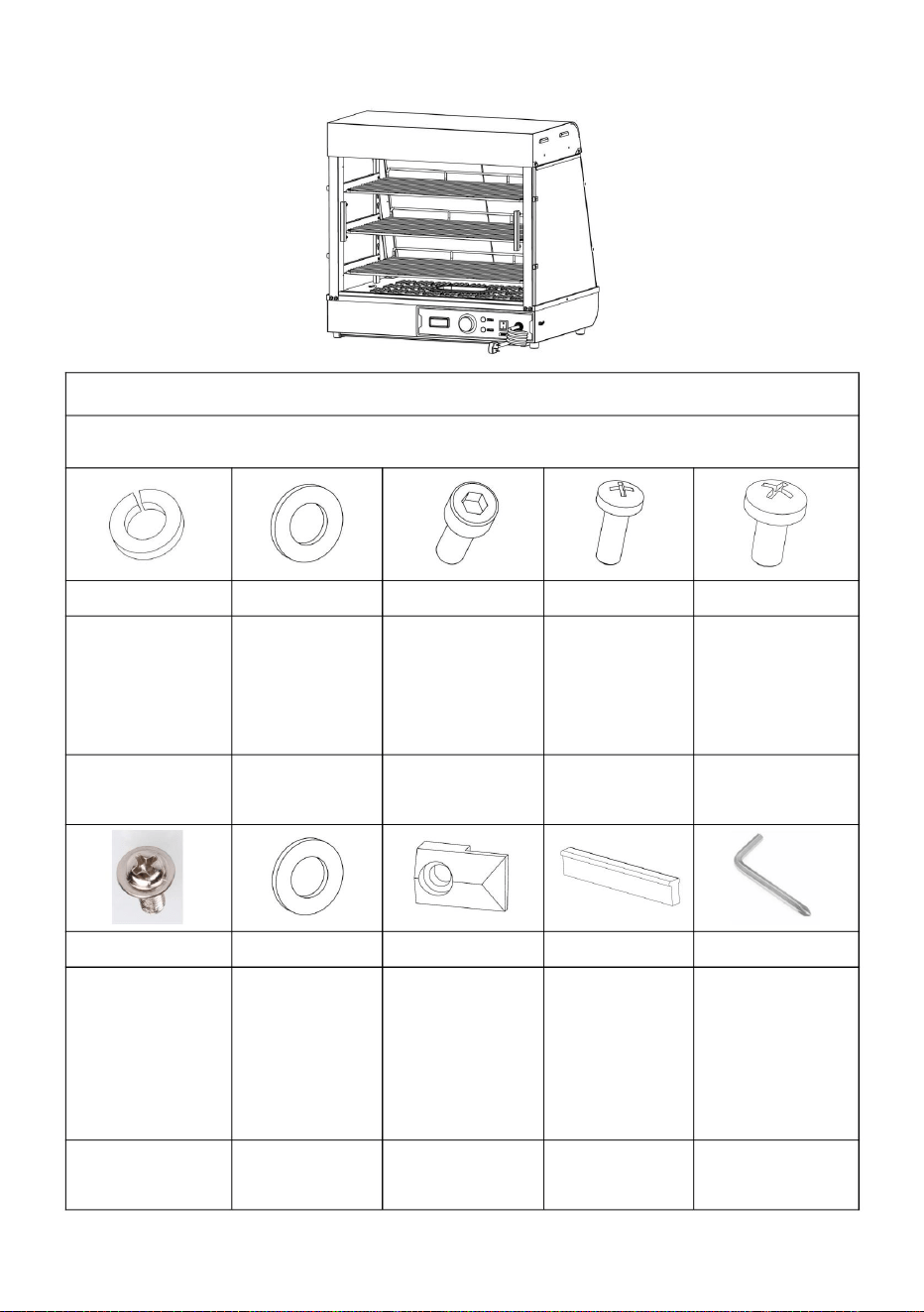
Gäller modeller: SC-CJ-601, SC-CJ-602, SC-CJ-603, SC-CJ-60S
- 8 -
tvättmaskin
Svart
hållare
(8st)
M5X14
huvudskruvar
A
(8st)
Rostfri Silikon
hantera
(4st)
T-formad
M5X14
C
Svart vår
G
(60-tal inga)
(1 st)
Glas kort
Svart platt
D
M4X8
Svart
jag
(60-tal inga)
J
stål
runt huvud
hylsbultar
M5 M5
Skruvverktyg
ÿ8stÿ
(8 st)
stål vadderad
F
skruvar
B
(4st)
packning
(60-tal inga)
skruvar
M4X12
H
Rostfri
tvättmaskin
(8st)
aluminium
ÿ16stÿ
(8st)
OCH
Delarsats materialförteckning
Svart rund
sexhörning
9. Produktinstallationsschema:
Machine Translated by Google

(1 st)
ÿ
Under installationen kan du hitta skruvarna vars koder på bilden ovan matchar koderna
som är tryckta i skruvpaketet enligt de skruvar som krävs i monteringsstegen för enkel
installation!
K N
1 ST
Vänster främre pelare
Boll
Glas gångjärn
set
1 ST
M5X18
(1st)
L
Höger främre pelare
60S
Rostfri
ÿ
(1 st)
skruva
tillbehör
Obs: Ovanstående är alla tillbehör i tillbehörspaketet.
ÿ
Vänster bakpelare
Höger bakre pelare
Magnet
dörrpanel
Svart
Lista över monteringsdelar
ÿ
Hantera
En för
1 ST 1 ST
M
Exklusiv
Stålkors
varje topp
och botten
- 9 -
Machine Translated by Google

- 10 -
ÿ
ÿ Bakre glasdörr
2 st
1 ST
Hyllfäste-vänster
(en var)
ÿ
ÿ
Hyllfäste-höger
ÿ
1 ST
60S
Övre hylla - kortast
2 st
Skjutglas fram och bak
ÿ
Mellanhylla-medium
Sidoglas
tillbehör
ÿFrämre glasdörr
3 st
ÿ
ÿ
Nedre hyllan längst
3 st
4 st
Exklusiv
Hyllpelare
1 ST
ÿ
dörrar ( ingen 60-tal)
Machine Translated by Google

- 11 -
ÿ
L (1 st)
K (1 st)
Steg 1 (601 602 603)
Kontrollera om tillbehören är kompletta innan installation!
Steg 1 (60-talet)
Obs: Ovanstående är alla tillbehör som ingår i tillbehörspaketet.
M (1 st)
K
L
G (4st)
SC-CJ-60-serien Universal installationsdiagram
SC-CJ-60-serien Universal installationsdiagram
M
F (2 st)
I (1 st)
Machine Translated by Google

- 12 -
A (4st)
3.Detaljbild A ÿ
(1PCS) ÿ
(1PCS)
installation!
D (4st)
Obs: När du installerar kolonnerna på båda sidor, observera att sidan med hål i kolonnen
är vänd mot maskinens utsida för
2. Enligt ordningen på bilden, använd motsvarande skruvar: "D, A, B" för att låsa
tillbehören: "ÿ, ÿ" på de reserverade mutterhålen.
1. För ljussladdskontakten som sticker ut från basen genom kolonnen och häng den
ovanför kolonnen.
Detaljbild A
E (Specifikation: M5*14)
Steg 2
B (4st)
Machine Translated by Google

- 13 -
ÿ(1PCS)
ÿ(1PCS)
installation!
1. Enligt ordningen på bilden, använd motsvarande skruvar: "D, A, B" för att låsa
tillbehören: "ÿ, ÿ" på de reserverade mutterhålen.
A (4st)
Detaljbild A
Obs: När du installerar kolonnerna på båda sidor, observera att sidan med hål i kolonnen
är vänd mot maskinens utsida för
Specifikation
n: M5*14
Detaljbild A
D (4st)
B (4st)
Steg 3
Machine Translated by Google

- 14 -
Detaljbild B
M5*14
B
1. Använd skruv "C" för att fästa de fyra kolumnerna vid de reserverade muttrarna på basen
Detalj
Specifikation:
bild
Detaljbild A
C (4st)
på samma sätt som visas på den detaljerade bilden.
Steg 4
Machine Translated by Google

1
1
1. Anslut trådkontakten som sticker ut från topplocket till kontakten som hänger på
kolonnen och dra åt den, sätt sedan in den anslutna kontakten i kolonnen och
göm den.
Steg 5
Detaljbild A
Detaljbild A
M4*8
Specifikation:
- 15 -
Machine Translated by Google
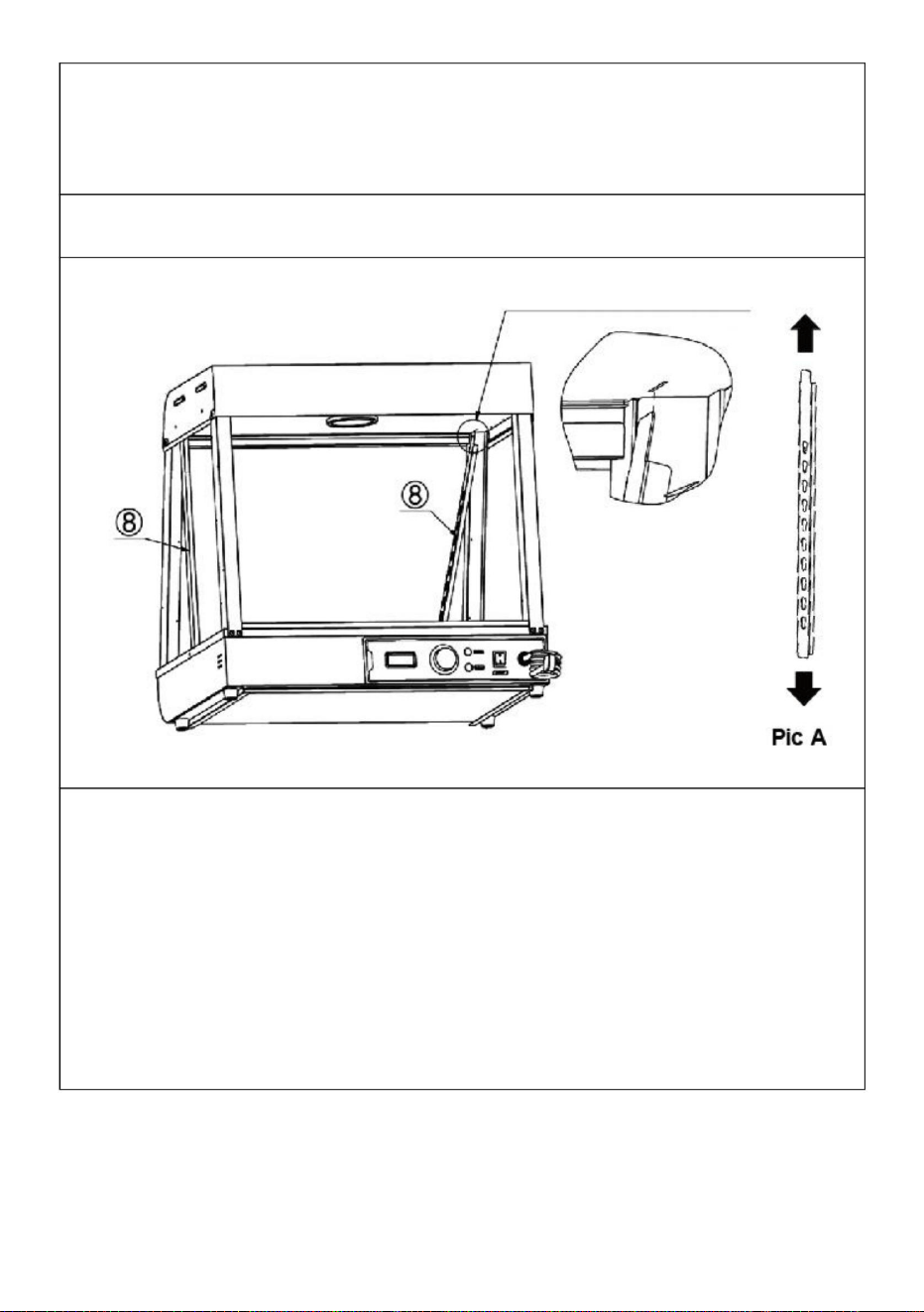
1
Steg 6
1. Rikta in de två vänstra och högra hyllstolparna "ÿ" på samma sätt i
riktningen för figur A, för in dem sedan diagonalt i de reserverade hålen
på toppen tills de är helt insatta och rikta in dem sedan.
E (4st)
1. Placera topplocket på de fyra upprättstående stolparna och använd sedan "skruvarna E"
för att fixera topplocket och de upprättstående stolparna (totalt fyra).
ÿ (2st)
Obs: Placeringen av tillbehör nr 8 är som visas i figuren. Det stora hålet
i kalebasshålet är vänt uppåt, det lilla hålet är vänt nedåt och skåran är
vänd mot maskinens utsida!
- 16 -
Machine Translated by Google
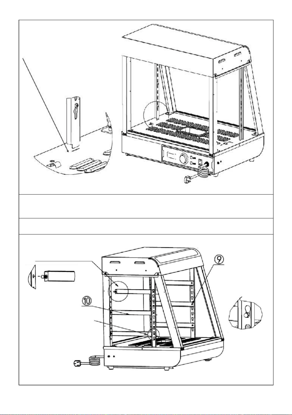
2. Se figur B och rikta in kolonnens botten med det reserverade hålet i
basplattan och placera den för att slutföra installationen.
Steg 7
1
2
2
- 17 -
Machine Translated by Google

1
2. Sätt sedan in spännespiken på baksidan av delen i kalebassmunnen som visas på bilden
nedan. ÿ (3PCS) ÿ (3PCS)
Steg 9 (601 602 603)
Obs: Placera den utskjutande delen av den I-formade spiken på hyllfästet mot utsidan av
maskinen för installation!
1. Sätt först in ramspiken på den främre delen av delen i det reserverade hålet i kolonnen
som visas nedan.
1. Placera delarna "ÿ, ÿ, ÿ" på hyllfästet enligt positionerna som visas på bilden och
tryck in dem i de reserverade skårorna som visas på bilden. ÿ (1 st) ÿ (1 st) ÿ (1 st)
Steg 8
- 18 -
Machine Translated by Google

1
2
1. Sätt först in de främre och bakre glasskjutdörrarna diagonalt i kortfacket
upptill, som visas i "Figur A"; efter att ha fört in det till yttersta läget, rikta in det
fallande glaset med kortfacket nedanför som är horisontellt och vertikalt mot det
övre kortfacket, som visas i "Figur A". Installationen slutförs som visas i "Figur
B". Totalt fyra glasskjutdörrar fram och bak monteras på samma sätt. ÿ (4st)
Bild A
- 19 -
Machine Translated by Google

- 20 -
Steg 9 (60S)
N (En för varje topp och botten)
1. Du måste installera den inre glasbiten först och sedan den yttre
glasbiten; 2.
Vid installation ska den övre kortplatsen vara i linje med den nedre kortplatsen
horisontellt och vertikalt!
Lägga märke till:
Installera dörrhandtaget före glasdörren (1 st)
1. Montera först det övre glasdörrgångjärnet på toppen av glasdörren och dra
åt skruvarna. Förbered sedan det nedre dörrgångjärnet i motsvarande
läge. Tryck slutligen in glasdörren till det förberedda läget för det nedre
gångjärnet, och dra sedan åt skruvarna på det nedre gångjärnet!
Machine Translated by Google

- 21 -
N (En för varje topp och botten)
Installationen är klar
2. Montera först det övre glasdörrgångjärnet på toppen av glasdörren och
dra åt skruvarna. Förbered sedan det nedre dörrgångjärnet i
motsvarande läge. Tryck slutligen in glasluckan till det förberedda läget för
det nedre gångjärnet, och dra sedan åt skruvarna på det nedre
gångjärnet!
Steg 10
Placeringen av de elektriska delarna är utformad vid den tiden,
företaget förbehåller sig rätten att ändra designen av utvärderingen,
när designen ändras och inte förbättrar manualen i tid, hoppas
kunderna förstår!
Installera dörrhandtaget före glasdörren (1 st)
Machine Translated by Google
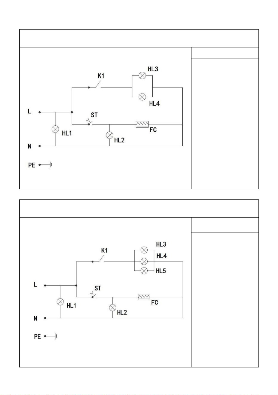
HL1: Kraft
HL3 varmljus
taklampa
HL2:
Värmeindikatorlampa
HL2:
Värmeindikatorlampa
indikator ljus
SC-CJ-60S/SC-CJ-601 Elschema
ST: Termostat
HL4: Taklampa
med varmt ljus 2
HL5:LED ljusrör
FC: värmerör
HL4:LED ljusrör
HL3: Taklampa
med varmt ljus 1
K1: Ljusbrytare
Illustrera
ST: Termostat
Illustrera
SC-CJ-602/SC-CJ-603 Elschema
FC: värmerör
indikator ljus
K1: Ljusbrytare
HL1: Kraft
10. Kretsschema
- 22 -
Machine Translated by Google

ÿSätt i nätsladden
ordentligt
02
temperaturkontroll är normalt
Indikeringslampan
brändes ut
Isoleringen är
Det finns en stickande
känsla i
avdelning för reparation.
ÿSätt tillbaka
indikatorlampan
Strömbrytare säkring
Arbetsindikatorn
fuktig eller innerledaren
är inne
ÿSätt i den ordentligt
Metod av
01
lampan lyser och
temperaturökningen
kan inte kontrolleras.
påslagen.
uteslutning
03
05
kontakt med
Anledning
värma.
ÿ Dra åt elvärmarörets
ledningsbultar. ÿByt ut
det
elektriska
värmeröret
Indikatorlampan är släckt
och
Kabeln
värmeröret är
utbränt.
Indikatorlampan tänds
inte när enheten är
det
Den kan
inte behållas automatiskt
ÿ Skicka den till
underhållet
Ljuset tänds inte eller
flimrar.
blåst
händer på grund av läckage
från höljet.
ÿByt ut termostaten
ÿByt ut termostaten
07
ansluten eller har dålig
kontakt.
04
06
Termostatfel
NEJ. Felfenomen
Elvärmarörskabeln
är lös och den elektriska
Termostatfel
yttre skal.
ÿByt ut mot en lämplig
säkring
De gröna och röda
indikatorlamporna lyser
samtidigt och temperaturen
stiger inte.
gränssnittet är det inte
11. Felanalys och felsökning:
- 23 -
Machine Translated by Google

UK REP
EC REP
E-CrossStu GmbH
YH CONSULTING LIMITED. C/O YH Consulting Limited
Office 147, Centurion House, London Road, Staines-
upon-Thames, Surrey, TW18 4AX
Importerad till AUS: SIHAO PTY LTD. 1 ROKEVA STREETEASTWOOD NSW 2122
Australien
Vänligen förvara denna manual på rätt sätt
Importerad till USA: Sanven Technology Ltd. Suite 250, 9166 Anaheim Place,
Rancho Cucamonga, CA 91730
Tillverkare: Shanghaimuxinmuyeyouxiangongsi Adress:
Shuangchenglu 803nong11hao1602A-1609shi, baoshanqu, shanghai 200000 CN.
Obs: Ovanstående problem är endast för analys och referensanvändning. Ta inte hand
om dem själv. Relevanta fackmän krävs för att utföra felsökning och reparationer. Vid
säkerhetsavvikelser såsom läckage ska strömförsörjningen omedelbart brytas och
användningen avbrytas!
Mainzer Landstr.69,
60329 Frankfurt am Main.
- 24 -
Machine Translated by Google

Machine Translated by Google