(x2)
(x1)
(x1)
(x1)
(x1)
(x1)
(x1)
1/2"
11/16"
9/16"
3/4"
3/16"
(included)
325 lb (147kg)
1/2"
3/4"
(x2)
(x1)
BEFORE ASSEMBLY:
• Decide with what to fi ll your base
(sand is recommended)
• At least 2 adults recommended for setup
Pour le français, voir la page 2. Para el español, ver la página 3.
ASSEMBLY INSTRUCTIONS
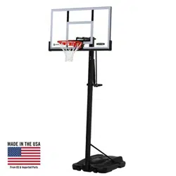
POWER LIFT
®
BASKETBALL SYSTEM
MODEL 71522
CONTACT LIFETIME CUSTOMER SERVICE:
QUESTIONS?
Model Number: 71522
Product ID:
For Customer Service in Mainland Europe
and the United Kingdom,
E-mail: [email protected]
Live Chat:
www.lifetime.com/customerservice/home
(Click on the “LIVE CHAT” tab)
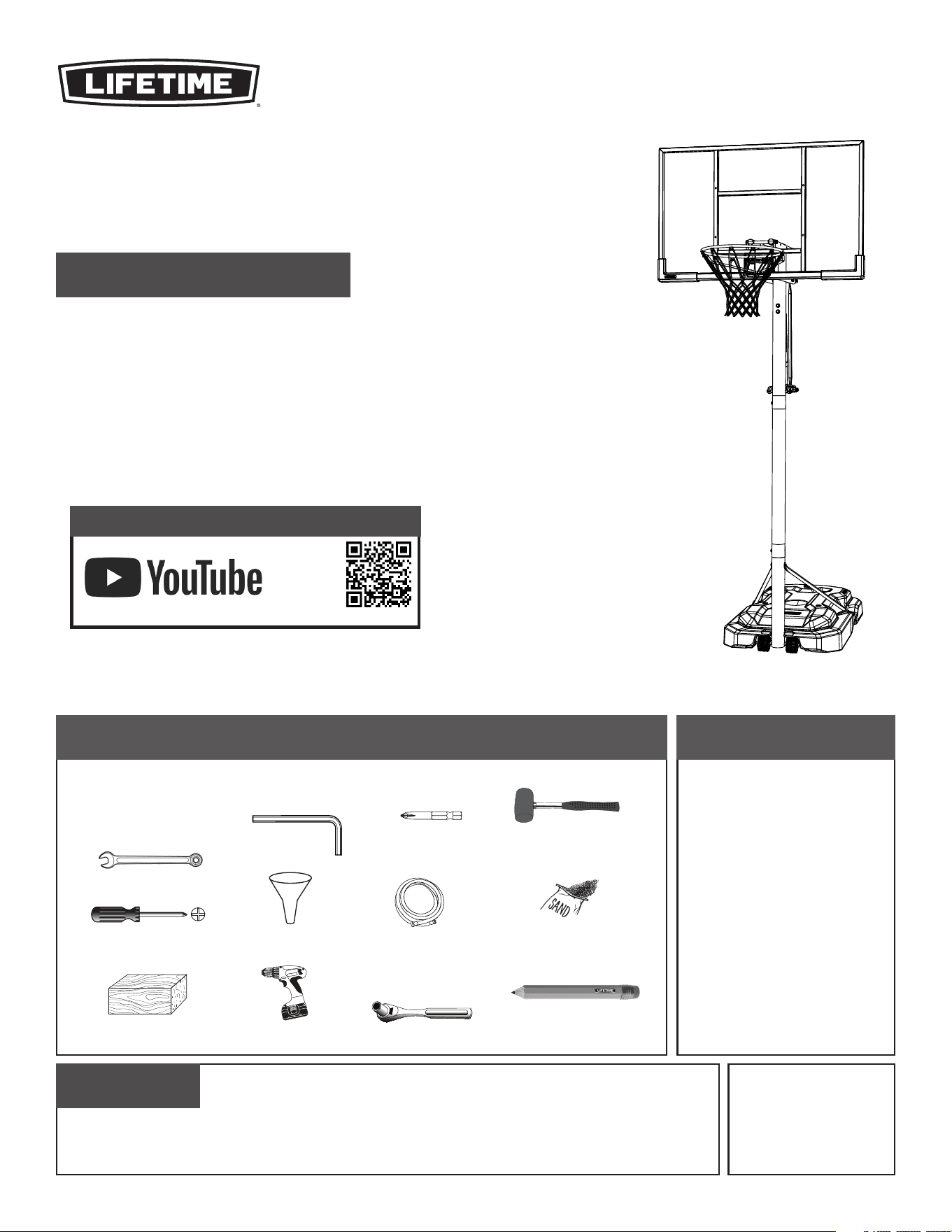
TOOLS REQUIRED TABLE OF CONTENTS
Icon legend................................4
Warnings & notices.....................5
Pole assembly............................6
Pole-to-base assembly...............11
Backboard-to-rim assembly........16
Backboard-to-pole assembly......21
Parts identifi er..........................i-iv
Handle assembly......................28
Final assembly..........................34
Maintenance........................39
Moving the system....................40
Warning sticker........................43
Registration........................44
Warranty................................45
Dial 1-800-225-3865
(English, French, Spanish)
Save this instruction in the event that the manufacturer has to be contacted for replacement parts.
IMPORTANT, RETAIN FOR FUTURE REFERENCE: READ CAREFULLY
Scan the code, or visit go.lifetime.com/71522powerlift-fullav
WATCH THE INSTRUCTIONAL VIDEO ON YOUTUBE
YouTube
®
and the YouTube logo are the registered trademarks of Google LLC.
(x1)
(x1)

2
(x2)
(x1)
(x1)
(x1)
(x1)
(x1)
1/2 po (≈13 mm)
11/16 po (≈18 mm)
9/16 po (≈14 mm)
3/4 po (≈19 mm)
3/16 po (≈5 mm)
(incluses)
147kg (325 lb)
Légende des icônes.......................4
Avertissements et avis...................5
Assemblage du poteau...................6
Assemblage du poteau à la base...11
Assemblage du panneau à
l’anneau...................................16
Assemblage du panneau au
poteau...................................21
Identifi cateur de pièces.............i – iv
Assemblage de la poignée............28
Assemblage fi nal.........................34
Entretien..............................39
Déplacer le systèm......................40
Autocollant d’avertissement.........43
Enregistrement.....................44
Garantie...............................46
1/2 po (≈13 mm)
3/4 po (≈19 mm)
(x2)
(x1)
AVANT L’ASSEMBLAGE :
• Déterminer avec quoi remplir la base
(nous recommendons le sable)
• Nous recommendons, au moins, 2 adultes pour
l’assemblage
For English, see page 1. Para el español, ver la página 3.
INSTRUCTIONS D’ASSEMBLAGE
SYSTÈME DE BASKET-BALL
POWER LIFT
®
MODÈLE n° 71522
CONTACTER AUX SERVICES À LA CLIENTÈLE LIFETIME
®
:
Entretien en direct:
www.lifetime.com/customerservice/home
(Cliquer sur la languette « LIVE CHAT »)
QUESTIONS ?
N° de modèle : 71522
Référence du produit :
OUTILS REQUIS SOMMAIRE
Pour nos services à la clientèle du continent
européen et au Royaume-Uni,
E-mail :
Composer le 1-800-225-3865
(anglais, français, espagnol)
Conserver ces instructions au cas d’avoir besoin de contacter le fabricant pour obtenir des pièces de remplacement.
IMPORTANT, À CONSERVER POUR DE FUTURS BESOINS DE RÉFÉRENCE : À LIRE SOIGNEUSEMENT
(x1)
(x1)
Scanner le code, ou visiter go.lifetime.com/71522powerlift-fullav
REGARDER LA VIDÉO D’INSTRUCTION SUR YOUTUBE
YouTube
®
et le logotype YouTube sont des marques déposées de Google LLC.
3
(x2)
(x1)
(x1)
(x1)
(x1)
(x1)
(x1)
1/2 in (≈13 mm)
11/16 in (≈18 mm)
9/16 in (≈14 mm)
3/4 in (≈19 mm)
3/16 in (≈5 mm)
(incluido)
147kg (325 lb)
Leyenda de íconos......................4
Advertencias y avisos...................5
Ensamblaje del poste..................6
Ensamblaje del poste a la base...11
Ensamblaje del tablero al aro.....16
Ensamblaje del tablero al poste..21
Identifi cador de piezas..............i-iv
Ensamblaje de la manivela.......28
Ensamblaje fi nal.......................34
Mantenimiento.......................39
Deplazando el sistema...............40
Autoadhesivo de advertencia......43
Registro...............................44
Garantía................................47
1/2 in (≈13 mm)
3/4 in (≈19 mm)
(x2)
For English, see page 1. Pour le français, voir la page 2.
INSTRUCCIONES DE ENSAMBLAJE
MODELO n° 71522
SISTEMA DE BALONCESTO
POWER LIFT
®
ANTES DE ENSAMBLAR:
• Decidir con que llenar la base
(se recomienda la arena)
• Recomendamos, al menos, 2 adultos para el ensamblaje.
PONERSE EN CONTACTO CON LOS SERVICIOS DE CLIENTES LIFETIME
®
:
Chat en vivo:
www.lifetime.com/customerservice/home
(Cliquear en la lengüeta « LIVE CHAT »)
¿PREGUNTAS?
Número de modelo: 71522
ID del producto:
INSTRUMENTAL REQUERIDO
ÍNDICE
Para nuestros servicios a clientes en
el continente europeo y el Reino Unido,
correo eléctronico:
Macar al 1-800-225-3865
(inglés, francés, español)
Guardar estas instrucciones en el caso de tener que contactar el fabricante para obtener piezas de reemplazo.
¡IMPORTANTE: CONSERVAR PARA FUTURA REFERENCIA. LEER CUIDADOSAMENTE!
(x1)
(x1)
Escanear el código, o visitar go.lifetime.com/71522powerlift-fullav
MIRAR EL VIDEO INSTRUCTIVO EN YOUTUBE
YouTube
®
y el logotipo de YouTube
®
son marcas registradas de Google LLC.
4
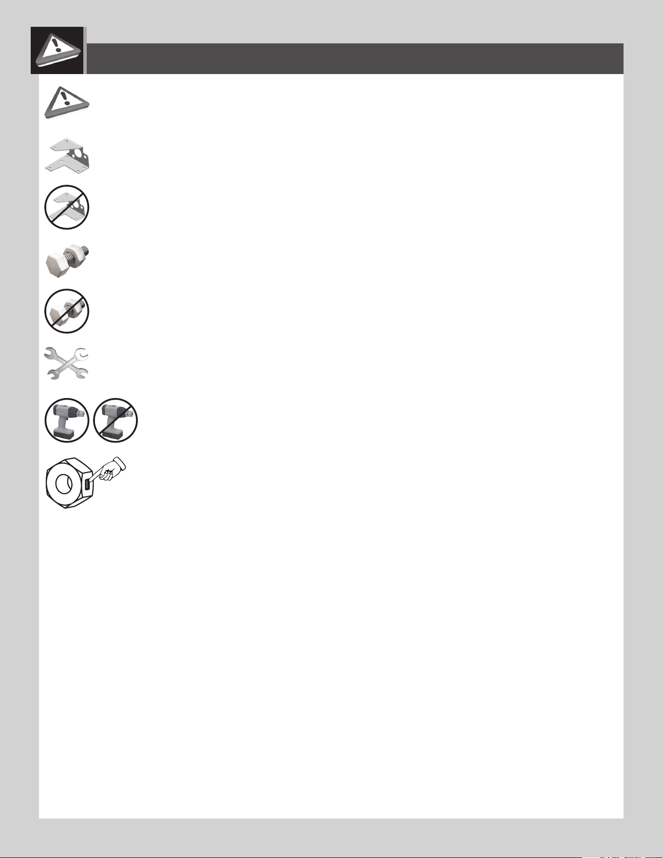
• Indicates the parts to be used for a section.
• Ceci indique les pièces requises pour une section.
• Indica las piezas requeridas para una sección.
• Indicates special heed should be taken when reading.
• Ceci indique que vous devez faire attention à ce que vous lisez.
• Indica que uno debe prestar atención al leer.
• Indicates the hardware to be used for a section.
• Ceci indique la quincaillerie requise pour une section.
• Indica el herraje requerido para una sección.
• Indicates the tools to be used for a section.
• Ceci indique les outils requis pour une section.
• Indica el instrumental requerido para una sección.
• Indicates no hardware required for a specifi c page.
• Ceci indique qu’il n’y a pas de quincaillerie requise pour une page particulière.
• Indica que ningún herraje es requerido para una página específi ca.
• Indicates no parts required for a specifi c section.
• Ceci indique qu’il n’y a pas de pièces requises pour une section particulière.
• Indica que ninguna pieza es requerida para una sección específi ca.
• Indicates to use/not to use an electric drill for a specifi c step.
• Ceci indique utiliser/ne pas utiliser de perceuse électrique pour une étape particulière.
• Indica usar/no usar un taladro eléctrico para un paso específi co.
ICON LEGEND / LÉGENDE DES ICÔNES / LEYENDA DE ÍCONOS
• Indicates the use of a centerlock nut. A nut with this marking will require some eff ort to tighten. This hardware was designed with this
feature in order to prevent loosening later.
• Cette image indique l’usage d’un écrou de blocage central. Un écrou avec ce marquage requerra plus d’eff ort pour le serrer. Cet
écrou a été conçu avec cette fonction afi n d’empêcher son desserrage plus tard.
• Indica el uso de una tuerca de bloque central. Una tuerca con esta marca requerirá un poco de esfuerzo para apretarlo. Esta tuerca
fue diseñado con esta característica con el fi n de evitar su afl ojamiento más tarde.
5
WARNINGS & NOTICES / AVERTISSEMENTS ET AVIS / ADVERTENCIAS Y AVISOS
Most injuries are caused by misuse and/or not following instructions. Use caution when using this product.
To ensure safety, do not attempt to assemble this product without following the instructions carefully. Check entire box and inside all packing
material for parts and/or additional instruction material. Before beginning assembly, read the instructions and identify parts using the hardware
identifi er and parts list in this document. Proper and complete assembly, use and supervision are essential for proper operation and to reduce the
risk of accident or injury. A high probability of serious injury exists if this product is not installed, maintained, and operated properly.
FAILURE TO FOLLOW THESE WARNINGS MAY RESULT IN SERIOUS INJURY OR PROPERTY DAMAGE AND WILL VOID WARRANTY.
Owner must ensure that all players know and follow these rules for safe operation of the system.
• If using a ladder during assembly, use extreme caution.
• Two capable adults are recommended for this operation.
• Check base daily for leakage. Leaks will cause system to fall.
• Assemble the pole sections properly. Failure to do so could cause the pole sections to separate during play or transport.
• Minimum operational height is 6 ft 6 in (1,98m) to the bottom of the backboard.
SAFETY INSTRUCTIONS
!
!
La mayoría de las lesiones son causadas por el abuso y/o por el no seguir las instrucciones. Ser cauteloso al usar este producto.
Para su seguridad, no intentar ensamblar este producto sin leer y seguir todas las instrucciones cuidadosamente. Revisar la caja entera y todos los
materiales de embalaje en busca de piezas y / o material de instrucciones adicional. Antes de comenzar el ensamble, identifi car todas las piezas y el
equipo usando las listas de partes y equipo así como los identifi cadores en este documento. El ensamblaje correcto y completo, el uso y la supervisión
son esenciales para una orientación apropiada y para reducir el riesgo de un accidente o lesión. Existe una alta probabilidad de sufrir lesiones graves
si este producto no es instalado, mantenido y / o operado correctamente.
EL INCUMPLIMIENTO DE SEGUIR ESTAS ADVERTENCIAS PUEDE OCASIONAR EN LESIONES GRAVES Y/O DAÑO A LA PROPIEDAD Y ANULARÁ LA GARANTÍA.
El propietario debe asegurarse de que todos los jugadores conocen y seguir estas reglas para la operación segura del sistema.
• Si se utiliza una escalera durante el ensamblaje, tener mucho cuidado.
• Se recomienda la participación de dos adultos capaces para este ensamblaje.
• Verifi car si hay fugas en la base. Las fugas pueden causar que el producto caiga.
• Ensamblar las secciones del poste correctamente. De lo contrario podría provocar que las secciones del poste se separaran durante el juego o
el transporte.
• Altura mínima de operación es 1,98m (6 ft 6 in) a la parte inferior del tablero.
!
INSTRUCCIONES DE SEGURIDAD
La majorité des accidents résultent d’une mauvaise utilisation et/ou du fait de n’avoir pas suivi les consignes. Observer toutes
précautions utiles pendant l’utilisation de ce produit.
!
Pour assurer votre sécurité, ne pas tenter d’assembler cet article sans avoir lu et suivi toutes les consignes attentivement. Vérifi er la totalité de la
boîte et l’intérieur de tous les matériaux d’emballage pour trouver toutes les pièces et/ou matériau contenant des consignes supplémentaires. Avant
de commencer le montage, identifi er toutes les pièces et tous les accessoires et faire l’inventaire en les comparant aux listes et identifi cateurs de
pièces et accessoires contenus dans ce document. Un assemblage correct et complet, ainsi que l’utilisation et la supervision correctes sont des
conditions essentielles à la bonne direction et diminuent les risques d’accident ou de blessure. Une haute probabilité d’accident grave résulte de
mauvaises conditions d’installation, maintenance et/ou utilisation.
LE NON-RESPECT DE CES AVERTISSEMENTS PEUT RÉSULTER EN ACCIDENTS GRAVES OU DOMMAGES MATÉRIELS ET ANNULER LA GARANTIE.
Le propriétaire doit veiller à ce que tous les joueurs connaissent et suivent ces règles pour une exploitation sûre du système.
• Agir avec la plus grande prudence si une échelle est utilisée pour l’assemblage.
• Il est recommandé que cet assemblage soit exécuté par deux personnes adultes.
• Vérifi er quotidiennement la base au niveau de fuites. Les fuites peuvent causer la chute du système.
• Assembler les sections de poteau correctement. La non-observation de cette consigne peut amener les sections de poteau à se séparer
pendant le jeu ou le déplacement.
• La hauteur minimale est 1,98m (6 pieds 6 po) au bas de la planche.
CONSIGNES DE SÉCURITÉ
!
!
6
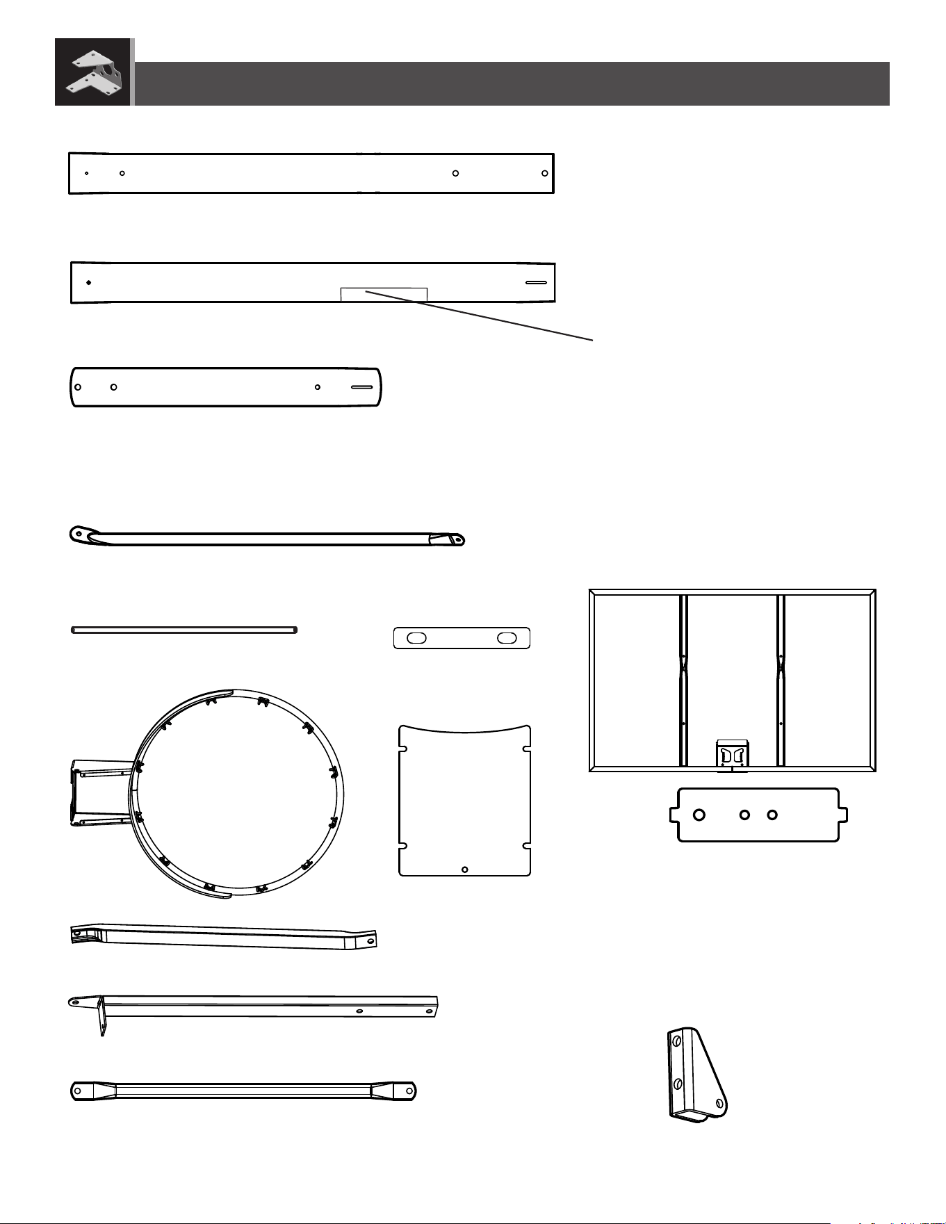
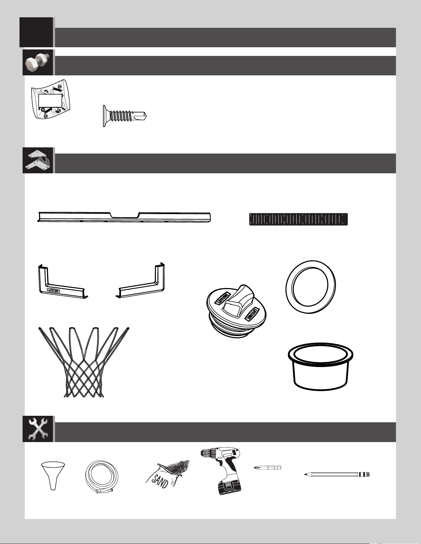
BCO
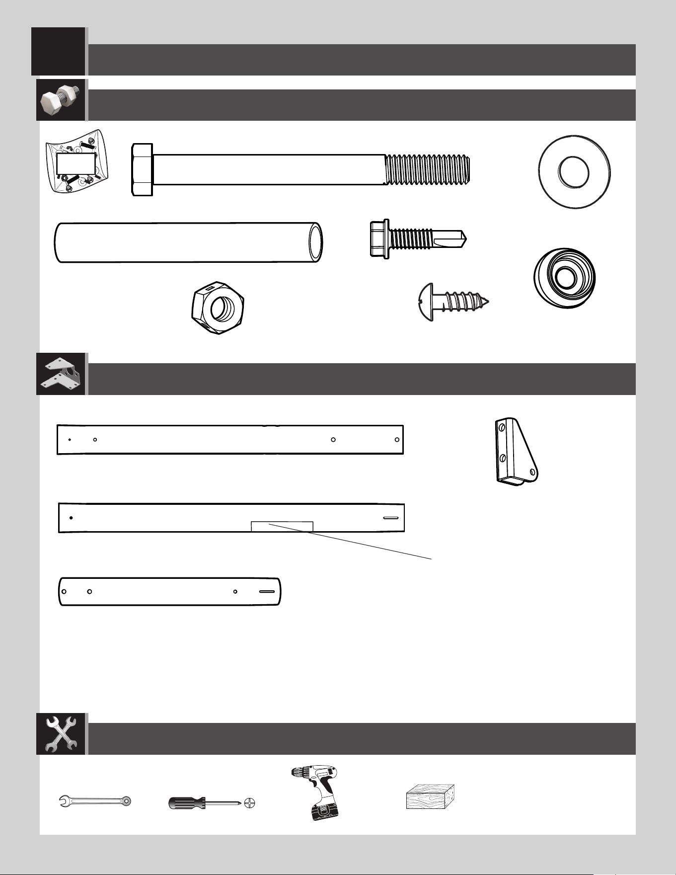
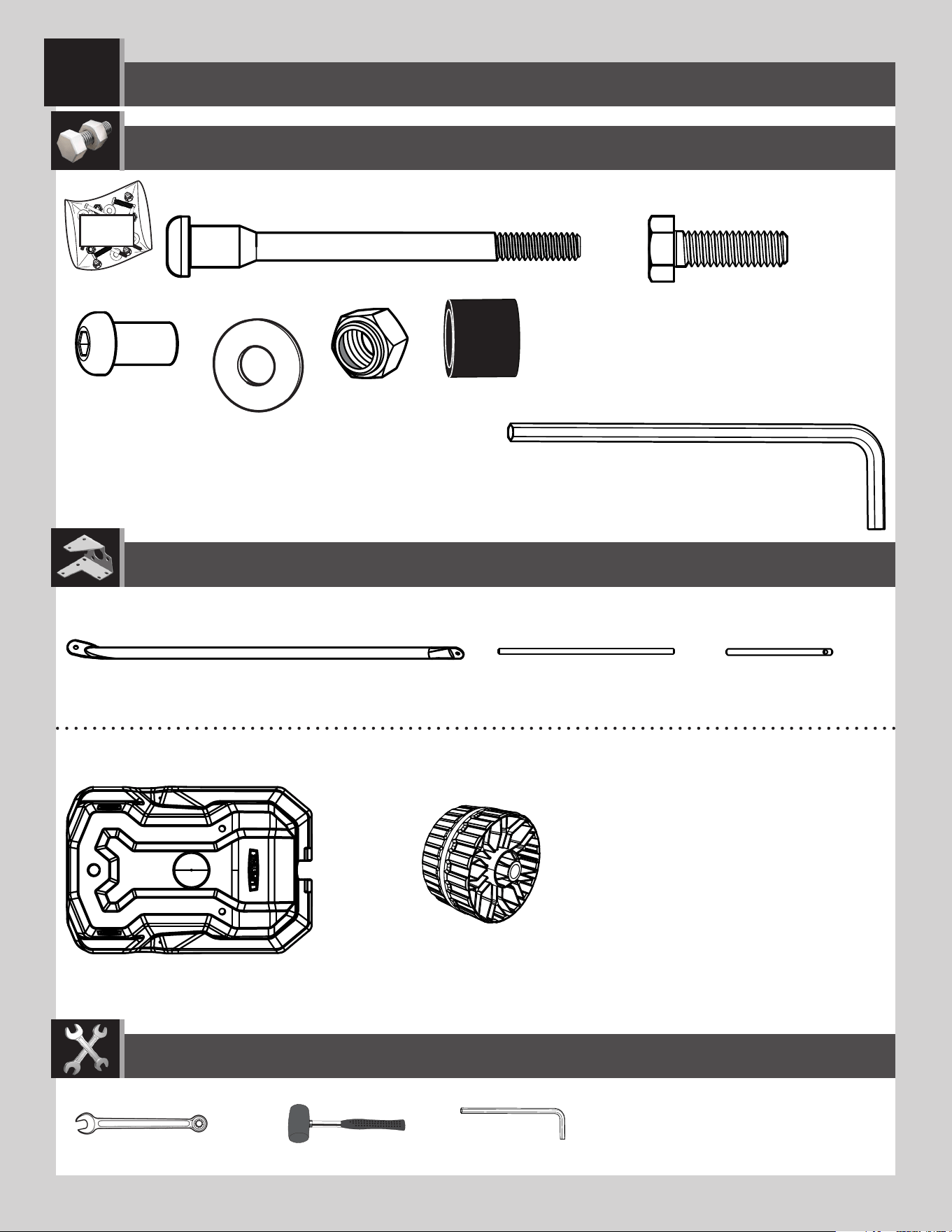
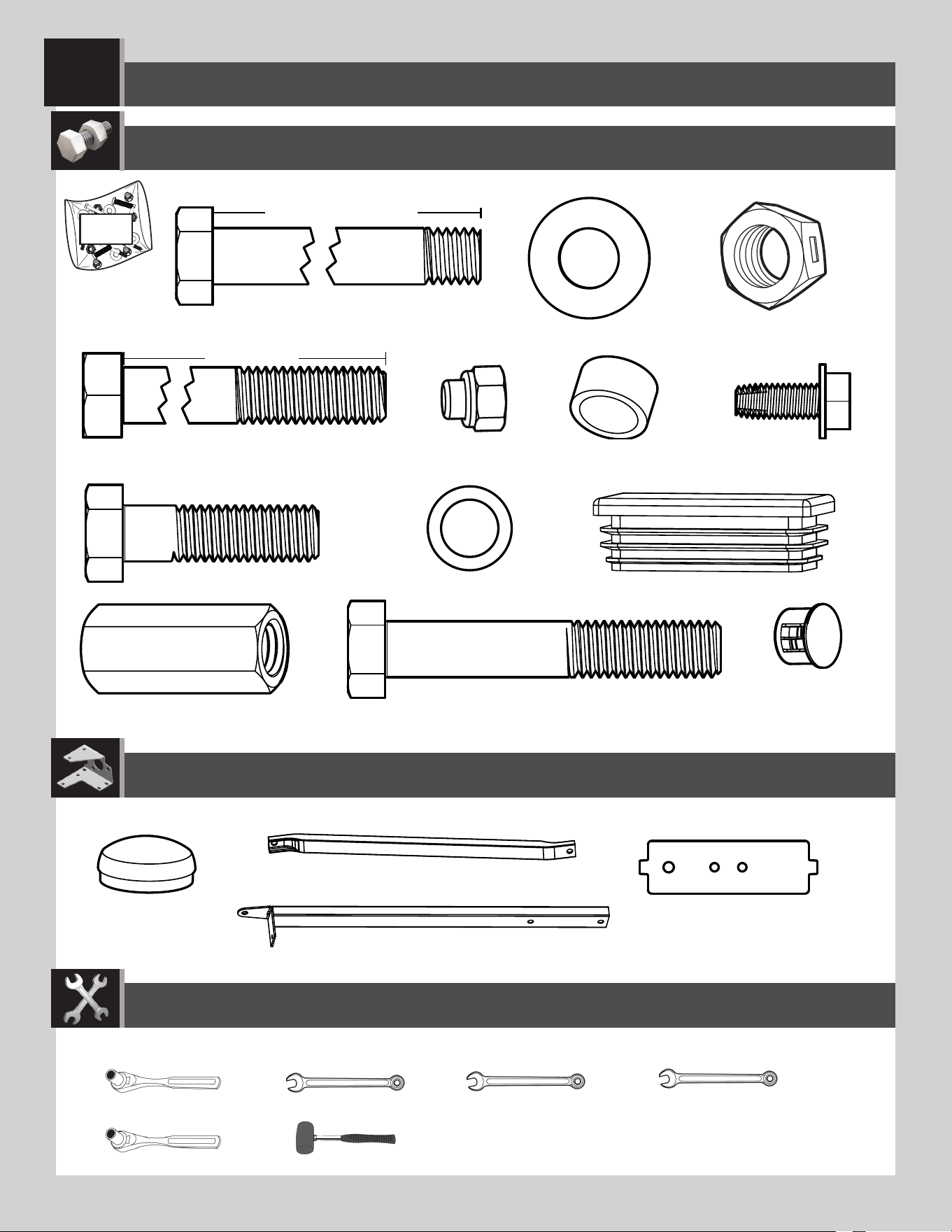
Metal parts / Pièces en métal / Piezas de metal
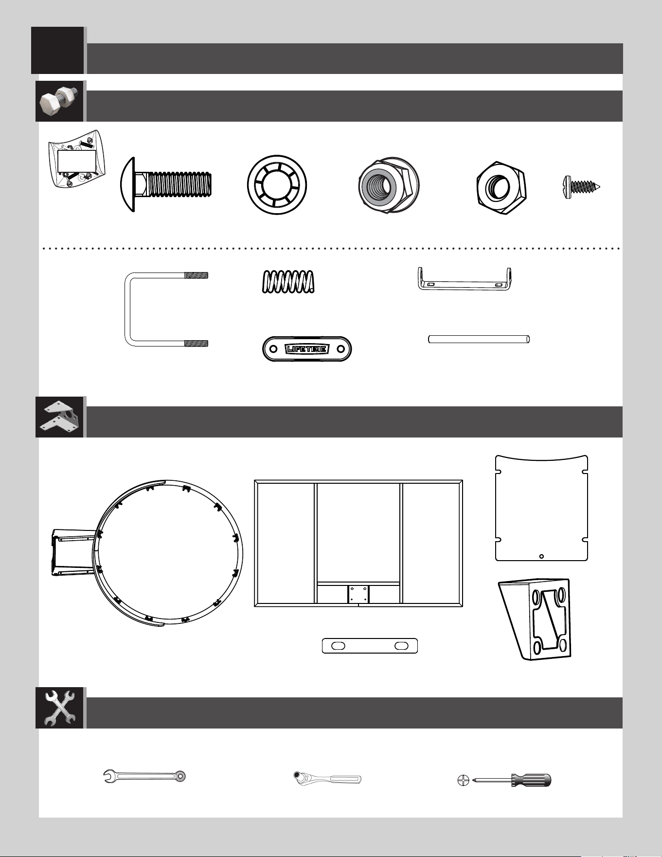
TOOLS REQUIRED / OUTILS REQUIS / INSTRUMENTAL REQUERIDO
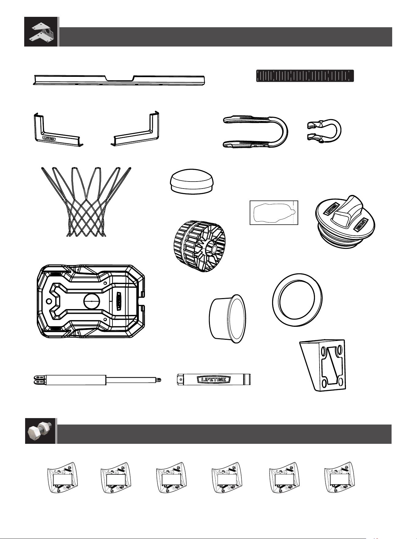
PARTS REQUIRED / PIÈCES REQUISES / PIEZAS REQUERIDAS
HARDWARE REQUIRED / QUINCAILLERIE REQUISE / HERRAJE REQUERIDO
POLE ASSEMBLY / ASSEMBLAGE DU POTEAU / ENSAMBLAJE DEL POSTE
1
Warning sticker
Autocollant d’avertissement
Autoadhesivo de advertencia
ADS (x2)
ABZ (x2)
ABB (x2)
AAF (x2)
ABE (x2)
ABR (x2)
CIH (x2)
9/16 in/po (≈14mm)
(x2)
ALH (x1)
ALF (x1)
(x1)
(x1)
(x1)
ALL (x1)
ALE (x1)
7
TOOLS AND HARDWARE REQUIRED / OUTILS ET QUINCAILLERIE REQUIS / INSTRUMENTAL Y HERRAJE REQUERIDOS
SECTION 1 (CONTINUED) / SECTION 1 (SUITE) / SECCIÓN 1 (CONTINUACIÓN)
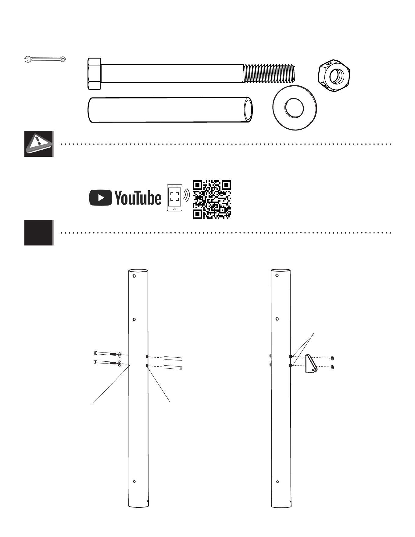
• In case of any problems with this section, scan the code below to view a video on its assembly.
• En cas d’avoir des problèmes avec cette section, scanner le QR code en dessous pour voir un vidéo de l’assemblage.
• En caso de tener problemas con esta sección, escanear el código QR debajo para ver un video del ensamblaje.
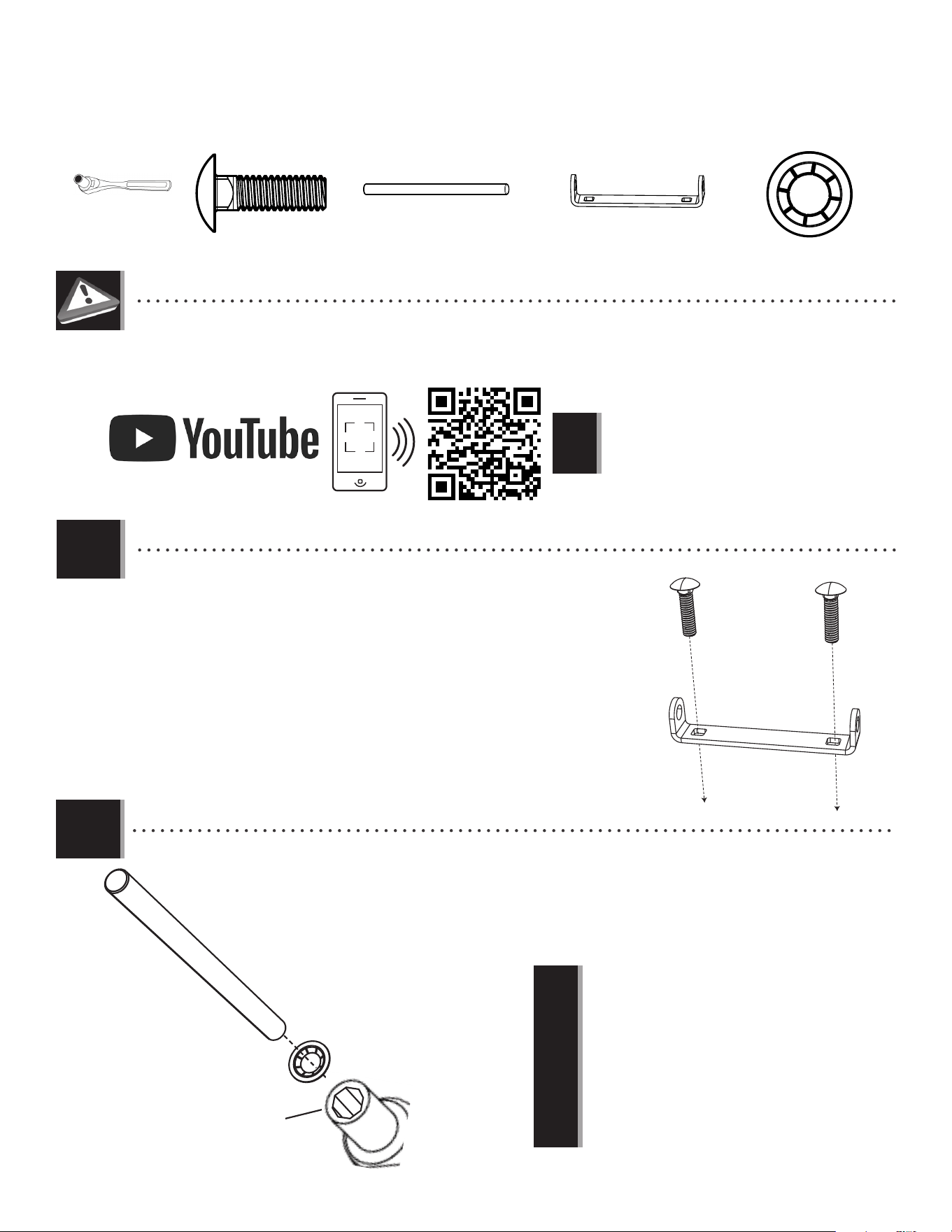
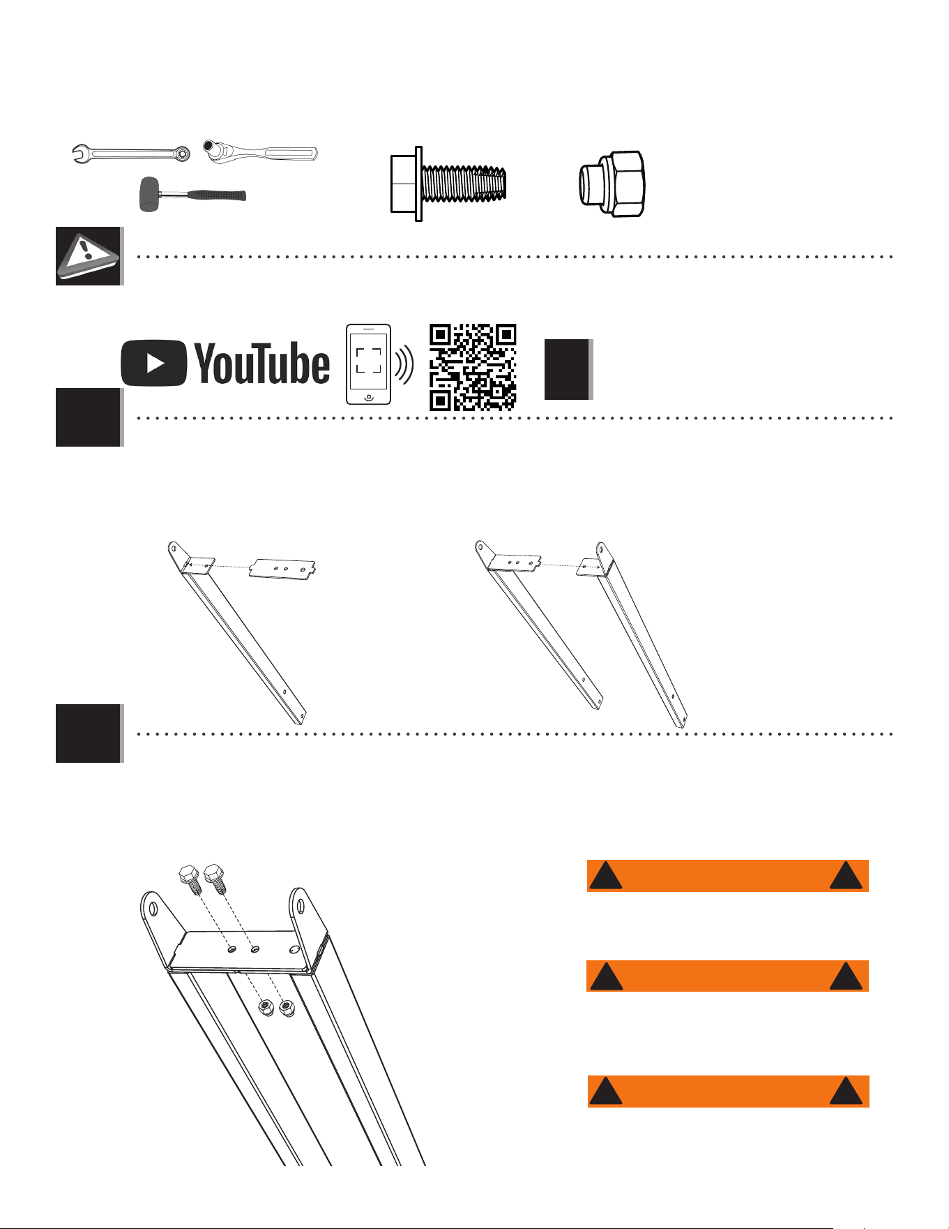
• Secure the pole bracket (ALL) to the top pole (ALH) with the hardware indicated.
• Attacher le support de poteau (ALL) au poteau supérieur (ALH) à l’aide de la quincaillerie indiquée.
• Sujetar el soporte de poste (ALL) al poste superior (ALH) usando el herraje indicado.
1.1
• http://go.lifetime.com/71522powerlift-section1
Large holes
Grands trous
Agujeros grandes
Small holes
Petits trous
Agujeros pequeños
AAF (x2)
ABE (x2)
ABR (x2)
9/16 in/po
(≈14mm) (x2)
ABB (x2)
ABE
AAF
ALH
ALH
ALL
ABB
ABE
ABR
8
TOOLS AND HARDWARE REQUIRED / OUTILS ET QUINCAILLERIE REQUIS / INSTRUMENTAL Y HERRAJE REQUERIDOS
SECTION 1 (CONTINUED) / SECTION 1 (SUITE) / SECCIÓN 1 (CONTINUACIÓN)
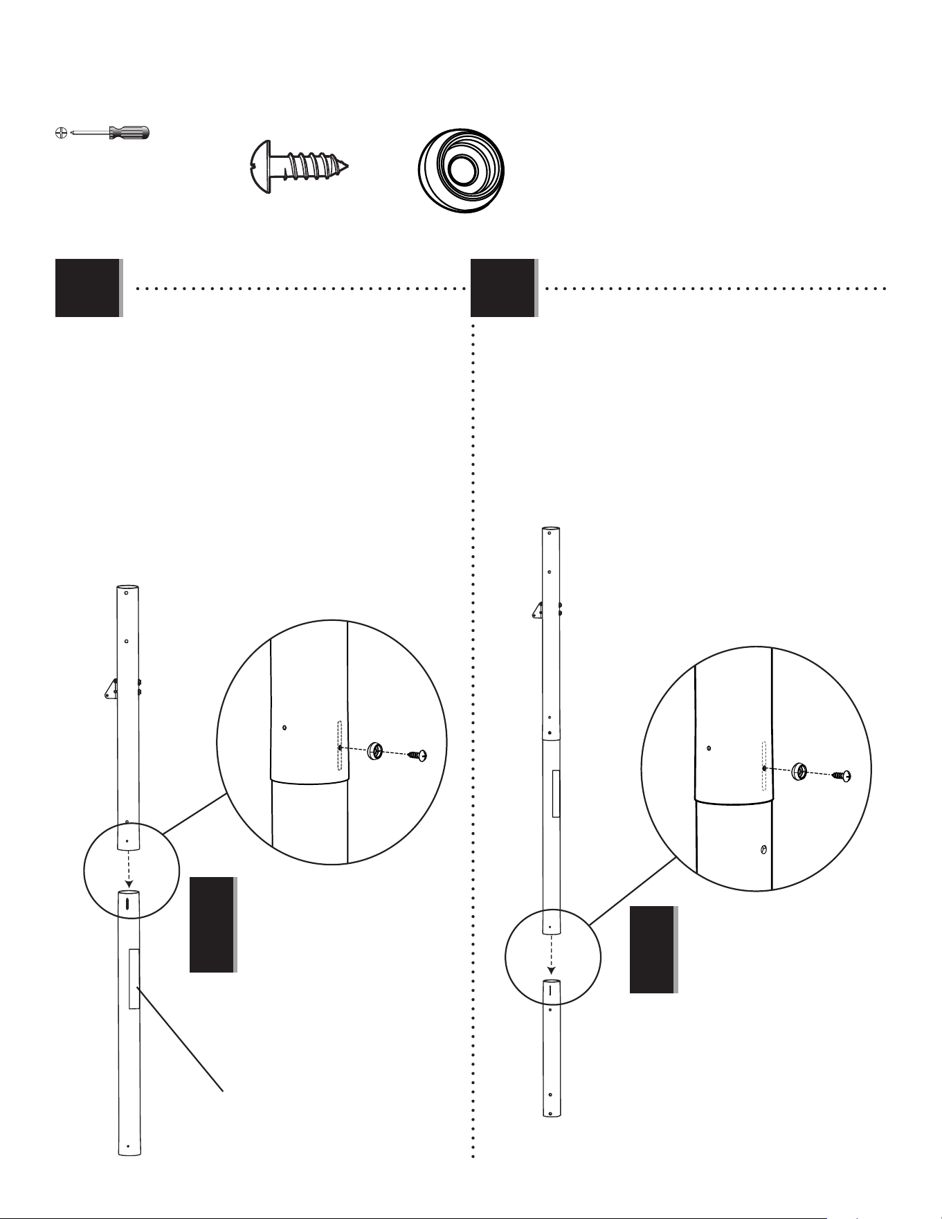
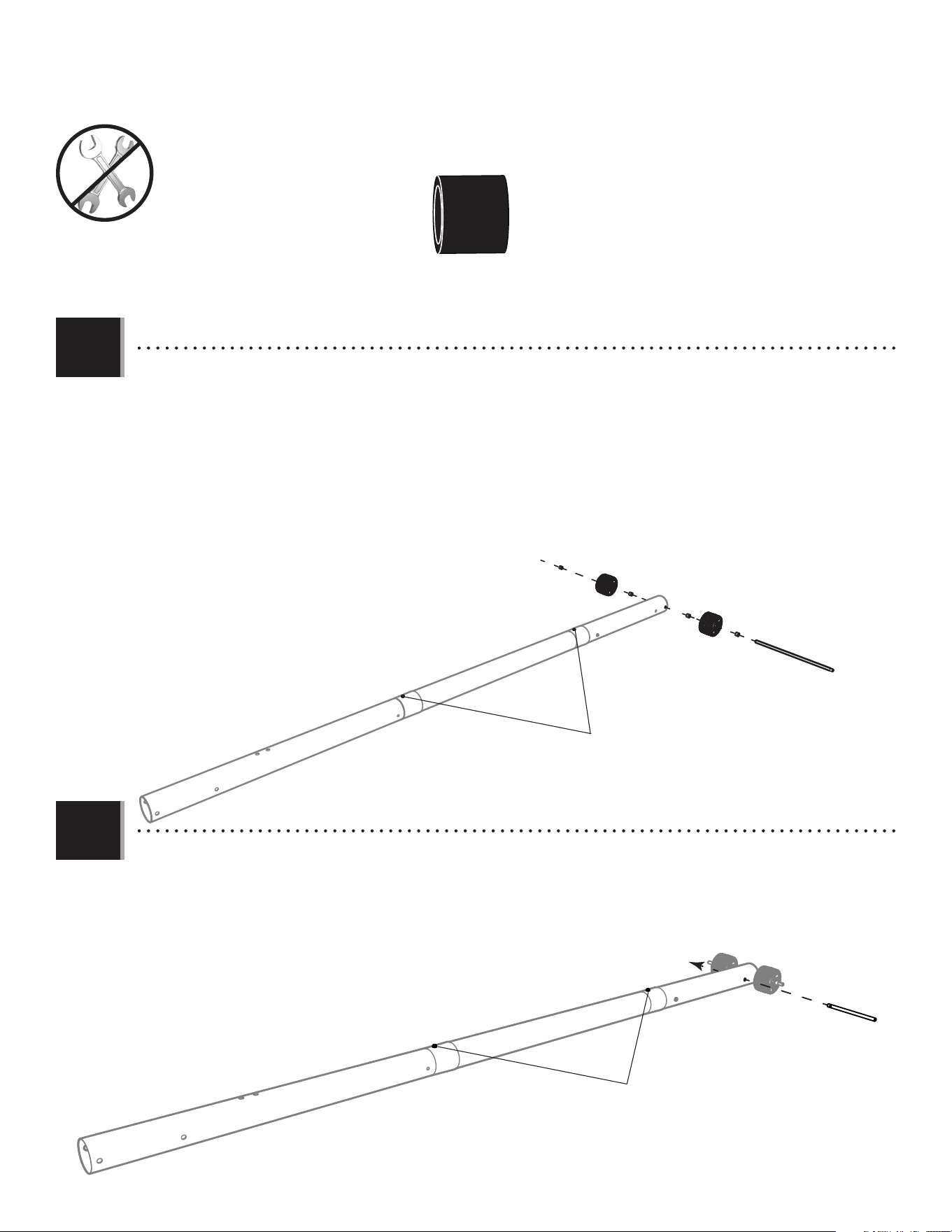
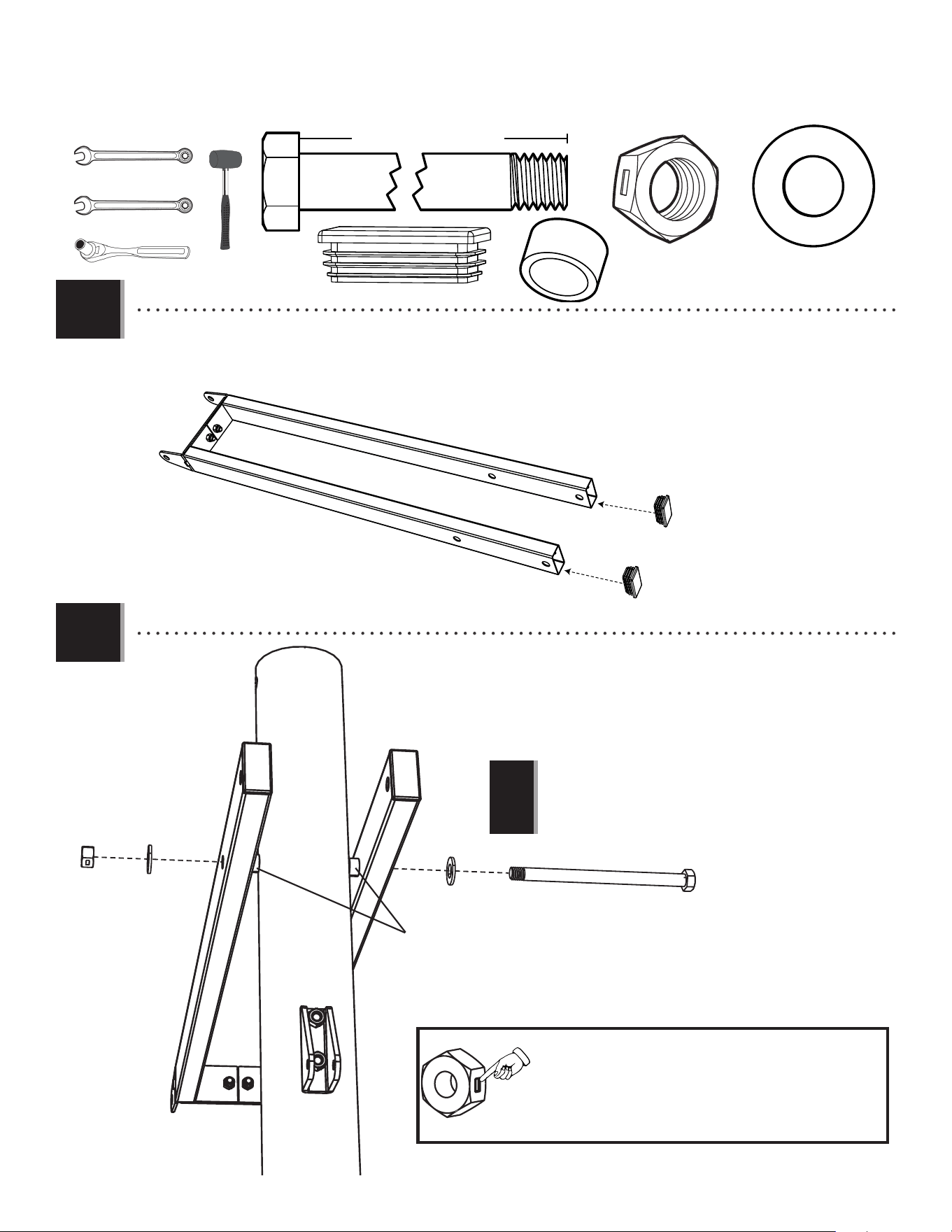
• Align the hole in the bottom of the top pole (ALH)
with the slot in the top of the middle pole (ALF). The
screw (ADS) simply helps to keep the holes in the poles
aligned during assembly.
• Aligner le trou dans la partie inférieure du
poteau supérieur (ALH) avec la fente dans la partie
supérieure du poteau du milieu (ALF). La vis (ADS) aide
simplement à maintenir les trous des poteaux alignés lors
du assemblage.
• Alinear el agujero en la parte inferior del poste
superior (ALH) con la ranura en la parte superior
del poste intermedio (ALF). El tornillo (ADS) simplemente
ayuda a mantener alineados los orifi cios de los postes
durante el ensamblaje.
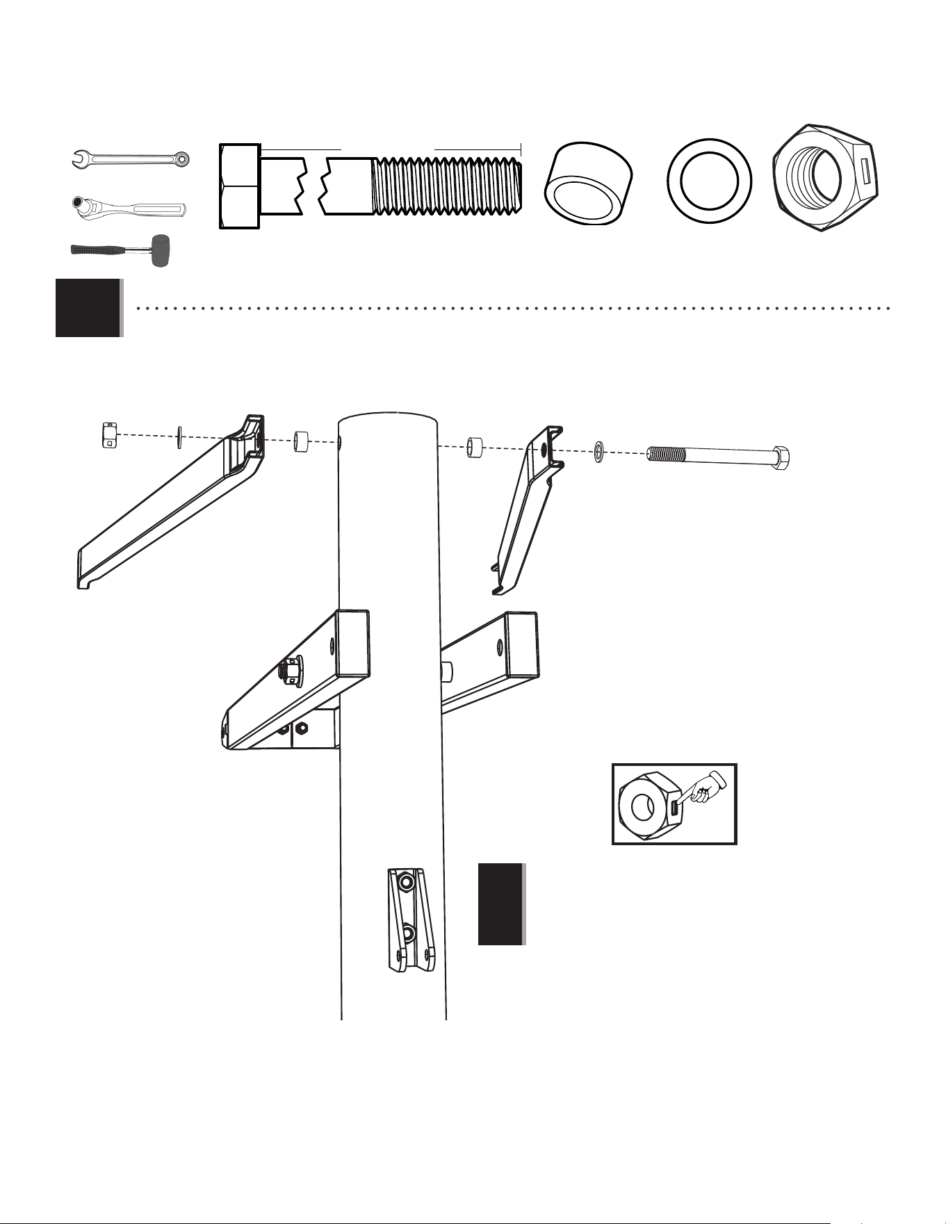
• Secure the middle pole to the bottom pole (ALE) using
the same method as step 1.2. The screw (ADS) simply
helps to keep the holes in the poles aligned during assembly.
• Attacher bien le poteau du milieu au poteau inférieur
(ALE) en utilisant le même méthode de l’étape 1.2. La
vis (ADS) aide simplement à maintenir les trous des poteaux
alignés lors du assemblage.
• Sujetar el poste intermedio al poste inferior (ALE)
usando el mismo método del paso 1.2. El tornillo
(ADS) simplemente ayuda a mantener alineados los orifi cios
de los postes durante el ensamblaje.
1.2 1.3
!
• The screw should be fl ush with the pole,
but will spin freely once inserted.
• La vis doit ser au ras du poteau, mais elle
tournera librement une fois insérée.
• El tornillo debe estar a ras del poste, mas
girará libremente una vez insertado.
Warning sticker
Autocollant d’avertissement
Etiqueta adhesiva de advertencia
!
• The screw should be fl ush with the pole,
but will spin freely once inserted.
• La vis doit ser au ras du poteau, mais
elle tournera librement une fois insérée.
• El tornillo debe estar a ras del poste,
mas girará libremente una vez insertado.
1.2
ADS (x2)
1.3
CIH (x2)
ALH
ALF
ADS
ADS
ALF
ALH
CIH
ALH
ALF
ALE
ALE
ALF
CIH
(x1)
9
TOOLS AND HARDWARE REQUIRED / OUTILS ET QUINCAILLERIE REQUIS / INSTRUMENTAL Y HERRAJE REQUERIDOS
SECTION 1 (CONTINUED) / SECTION 1 (SUITE) / SECCIÓN 1 (CONTINUACIÓN)
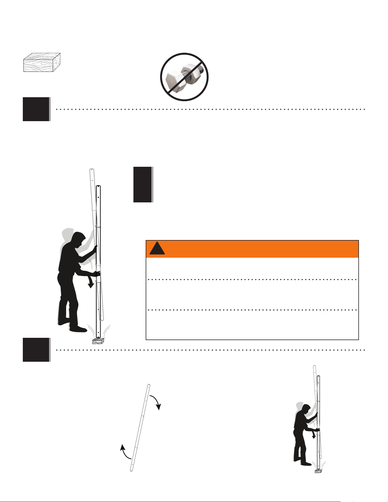
• THIS STEP CANNOT BE REVERSED! Strike the end of the pole assembly on a piece of scrap wood or cardboard 5–6
times.
• CETTE ÉTAPE EST IRRÉVERSIBLE ! Frapper l’extrémité de l’assemblage du poteau sur une chute de bois ou carton 5–6
fois.
• ¡ESTE PASO NO SE PUEDE REVERTIR! Golpear el extremo del ensamble del poste en una plaquita de madera o cartón
5–6 veces.
1.4
6x
•
Do not strike your feet with the pole sections, as serious injury may occur.
•
Ne pas se cogner les pieds avec les sections du poteau ; ceci peut causer des blessures
graves.
•
No golpee los pies con las secciones del poste, ya que esto puede ocasionarle graves
lesiones.
!
• Flip the pole over and repeat step 1.4 for the opposite end of the pole assembly.
• Renverser le poteau, et répéter l’étape 1.4 pour l’extrémité opposée de l’assemblage du poteau.
• Dar la vuelta el poste, y repetir el paso 1.4 para el extremo opuesto del ensamble del poste.
1.5
6x
(x1)
WARNING / AVERTISSEMENT / ADVERTENCIA
The poles must be seated together! Even if the poles cover the slots before seating, they must
be struck on a hard surface five to six times! Failure to seat the poles correctly could allow the
poles to separate during use, which could lead to serious personal injuries or property damage.
¡Los postes deben quedar asentados de manera conjunta! Incluso si los postes cubren las ranuras
antes de quedar asentados, ¡deben ser golpeados sobre una superficie dura de cinco a seis veces! Si
no se asientan correctamente los postes, eso podría permitir que los postes se separen durante el uso,
lo que podría provocar graves lesiones personales o daños a la propiedad.
Les poteaux doivent s’enclencher les uns les autres! Même si les poteaux recouvrent les
fentes avant de s’enclencher, il faut les frapper sur un morceau de bois cinq à six fois!
Un mauvais enclenchement des poteaux peut entraîner leur séparation lors de
l’utilisation, et causer des blessures graves et endommager le matériel.
!
10
TOOLS AND HARDWARE REQUIRED / OUTILS ET QUINCAILLERIE REQUIS / INSTRUMENTAL Y HERRAJE REQUERIDOS
SECTION 1 (CONTINUED) / SECTION 1 (SUITE) / SECCIÓN 1 (CONTINUACIÓN)
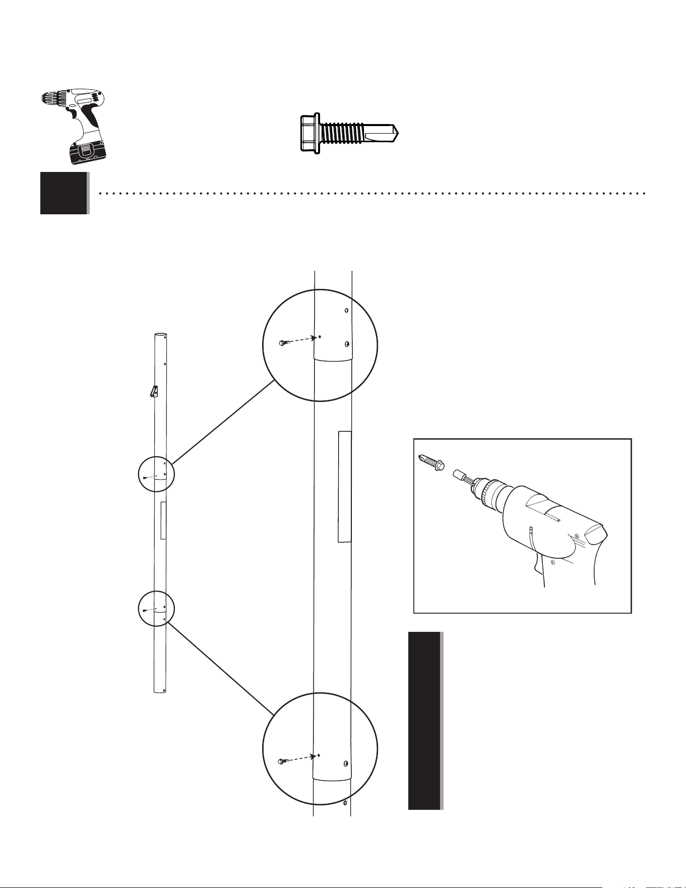
• Secure the poles together with self-drilling screws (ABZ).
• Attacher les poteaux l’un à l’autre à l’aide des vis autotaraudeuses (ABZ).
• Sujetar los postes el uno al otro con tornillos autoroscantes (ABZ).
1.6
ABZ (x2)
ABZ
ABZ
(x1)
• THE SCREWS (ABZ) ARE DESIGNED TO DRILL
INTO THE METAL OF THE UNDERLYING POLE.
For ease of installation, chuck the self-drilling
screws directly into the drill, or use a 3/8-inch
(≈10 mm) hex driver.
• LES VIS (ABZ) SONT CONÇUES POUR FORER À
TRAVERS LE MÉTAL DU POTEAU SOUS-JACENT.
Pour faciliter l’installation, mettre les vis
autotaraudeuses directement dans la perceuse, ou
utiliser un tournevis à écrou de 3/8 po (≈10 mm).
• LOS TORNILLOS (ABZ) ESTÁN DISEÑADOS PARA
PERFORAR EL METAL DEL POSTE SUBYACENTE.
Para facilitar la instalación, fi jar los tornillos
autoroscantes directamente en el taladro, o usar
una llave de tuerca de 3/8 in. (≈10 mm).
!
11
POLE-TO-BASE ASSEMBLY / ASSEMBLAGE DU POTEAU A LA BASE / ENSAMBLAJE DEL POSTE A LA BASE
2
BCQ
Metal Parts / Pièces en métal / Piezas de metal
TOOLS REQUIRED / OUTILS REQUIS / INSTRUMENTAL REQUERIDO
PARTS REQUIRED / PIÈCES REQUISES / PIEZAS REQUERIDAS
HARDWARE REQUIRED / QUINCAILLERIE REQUISE / HERRAJE REQUERIDO
AAE (x2)
BTS (x1)
ABD (x4)
AAO (x2)
EEO (x2)
AMU (x2)
AJM (x1)
Plastic Parts / Pièces en plastique / Piezas de plástico
(x2) (x1)
3/16" (≈5 mm)
(x2)
AJC (x1)
HJX (x1)
ABL (x4)
ALI (x2)
DRZ (x1)
1/2" (≈13 mm)
(Not actual size)
(Pas à l’échelle)
(No a la escala)
Axle / Essieu / Eje Axle / Essieu / Eje
12
TOOLS AND HARDWARE REQUIRED / OUTILS ET QUINCAILLERIE REQUIS / INSTRUMENTAL Y HERRAJE REQUERIDOS
SECTION 2 (CONTINUED) / SECTION 2 (SUITE) / SECCIÓN 2 (CONTINUACIÓN)
2.1
2.2
• Lay the pole assembly down and slide the long axle (AJC) through a spacer (ABL), a wheel (AMU), a second spacer (ABL) and the
hole at the end of the bottom pole. Continue sliding the axle through a third spacer (ABL), the second wheel (AMU) and a fourth
spacer (ABL) as indicated. The ends of the axle should be equidistant from the center of the pole.
• Mettre l’assemblage du poteau sur le sol et faire glisser l’essieu long (AJC) à travers une entretoise (ABL), une roue (AMU), une
deuxième entretoise (ABL) et le trou au bas du poteau inférieur. Continuer a faire glisser l’essieu à travers une troisième
entretoise (ABL), la deuxième roue (AMU) et une quatrième entretoise (ABL) comme indiqué. Les extrémités de l’essieu doivent être
équidistantes du centre du poteau.
• Colocar el conjunto del poste en el suelo y faire glisser el eje largo (AJC) a través un espaciador (ABL), una rueda (AMU), un
segundo espaciador (ABL) y el agujero al fondo del poste. Continuar deslizando el eje a través de un tercer espaciador (ABL),
la segunda rueda (AMU) y un cuarto espaciador (ABL) como se indica. Los extremos del eje deben set ends of the axle should be
equidistantes del centro del poste.
• Slide the short axle (HJX) through hole next to the bottom hole so the ends of the axle are equidistant from the pole. Please
note that the two self-tapping screws from step 1.6 are on top.
• Faire glisser l’essieu court (HJX) à travers le trou à côté du trou inférieur pour que les extrémités de l’essieu soient
équidistantes du poteau. Vouloir noter que les deux vis autotaraudeuses de l’étape 1.6 se trouvent en haut.
• Deslizar el eje corto (HJX) a través del orifi cio junto al orifi cio inferior para que los extremos del eje estén equidistantes del
poste. Tenga en cuenta que los dos tornillos autorroscantes del paso 1.6 miran hacia arriba.
ABL
ABL
AMU
AMU
ABL
ABL
AJC
ABL (x4)
HJX
Self-tapping screws
Vis autotaraudeuses
Tornillos autorroscantes
Self-tapping screws
Vis autotaraudeuses
Tornillos autorroscantes
13
TOOLS AND HARDWARE REQUIRED / OUTILS ET QUINCAILLERIE REQUIS / INSTRUMENTAL Y HERRAJE REQUERIDOS
SECTION 2 (CONTINUED) / SECTION 2 (SUITE) / SECCIÓN 2 (CONTINUACIÓN)
AJM
Self-tapping screws
Vis autotaraudeuses
Tornillos autorroscantes
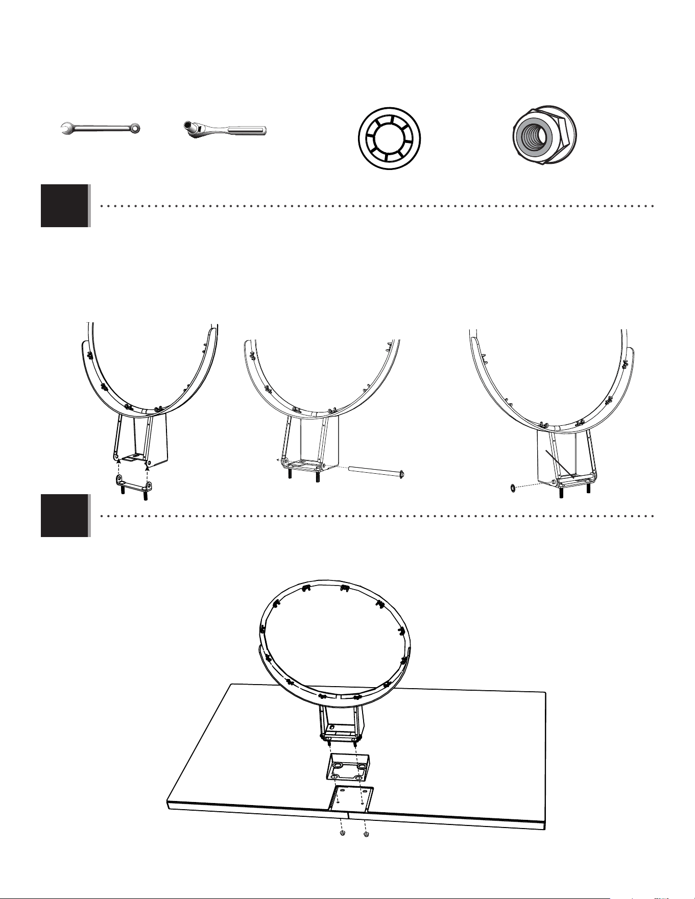
• Set the front of the base (AJM) over the long axle as indicated. The ends of the long axle should be up inside the recesses in
the bottom of the base. Please note that the two self-tapping screws from step 1.6 are on top. These should be on top in order to have all the
other holes in the pole sections oriented correctly.
• Mettre la parte frontale de la base (AJM) sur l’essieu long comme indiqué. Les extrémités de l’essieu long doivent être
dedans les rainures dans la partie inférieure de la base. Vouloir noter que les deux vis autotaraudeuses de l’étape 1.6 se trouvent en
haut. Ceux-ci doivent être sur le dessus afi n que tous les autres trous des sections de poteau soient correctement orientés.
• Colocar la parte delantera de la base (AJM) sobre el eje largo como se indica. Los extremos del eje largo deben estar dentro
de los huecos en la parte inferior de la base. Tenga en cuenta que los dos tornillos autorroscantes del paso 1.6 miran hacia arriba. Estos
deben estar en la parte superior para que todos los demás orifi cios en las secciones del poste estén orientados correctamente.
2.3
2.4
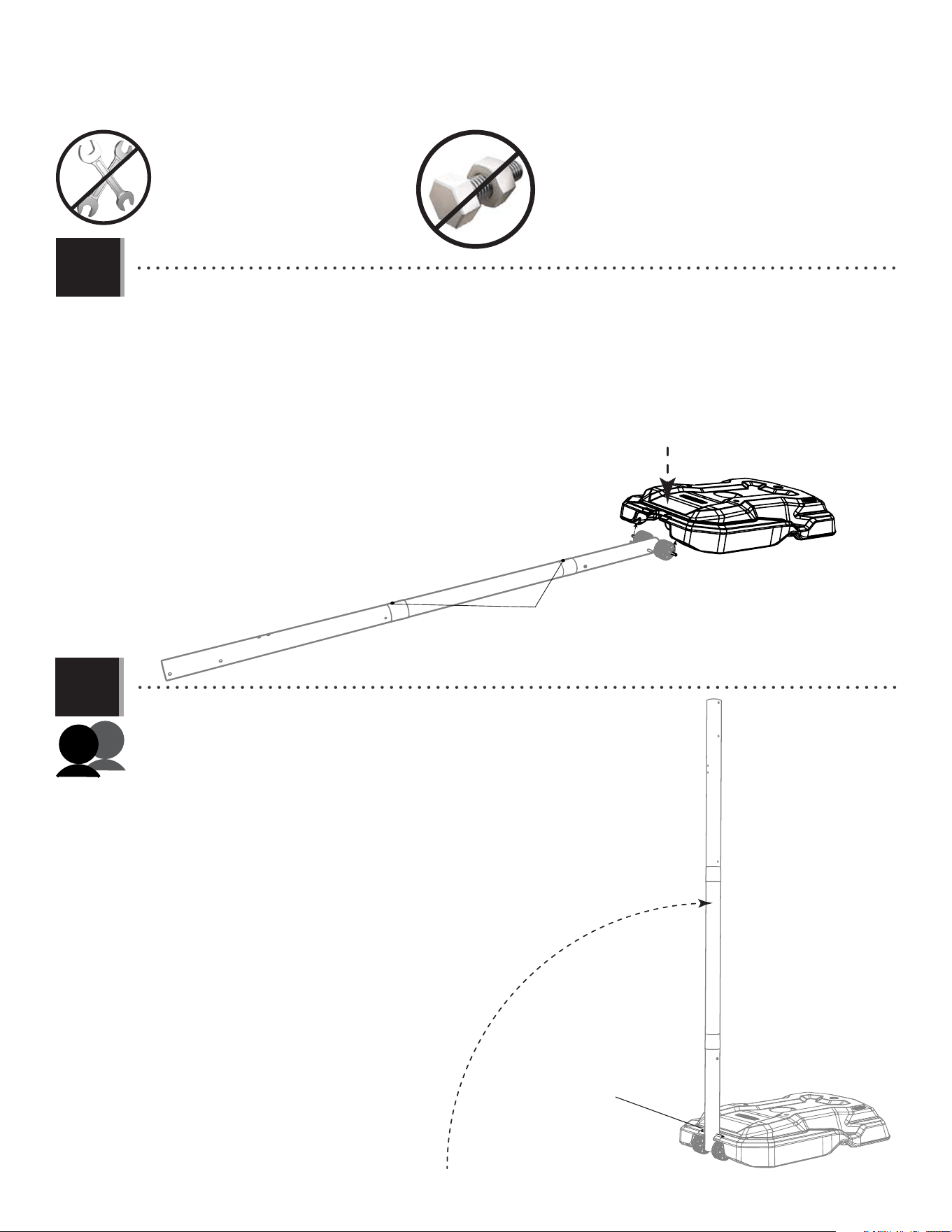
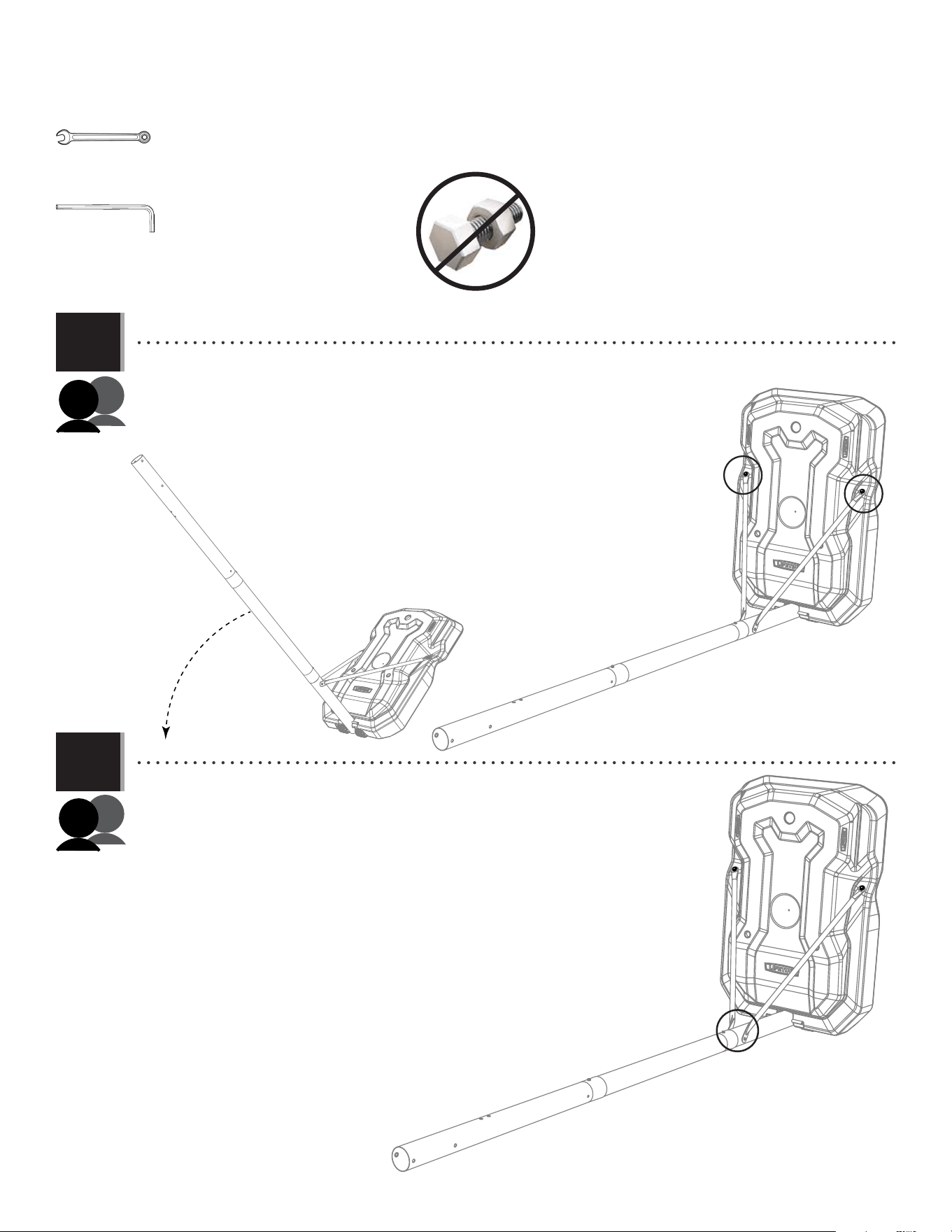
• Rotate the pole assembly upright until the short axle rests in the recess on top of the base.
• Lever l’assemblage du poteau à la verticale jusqu’à ce que l’essieu court repose dans la
partie supérieure de la base.
• Levantar el conjunto del poste vertical hasta que el eje corto se quede en el hueco en la
parte superior de la base.
Short axle
Esseau court
Eje corto
14
TOOLS AND HARDWARE REQUIRED / OUTILS ET QUINCAILLERIE REQUIS / INSTRUMENTAL Y HERRAJE REQUERIDOS
SECTION 2 (CONTINUED) / SECTION 2 (SUITE) / SECCIÓN 2 (CONTINUACIÓN)
2.5
2.6
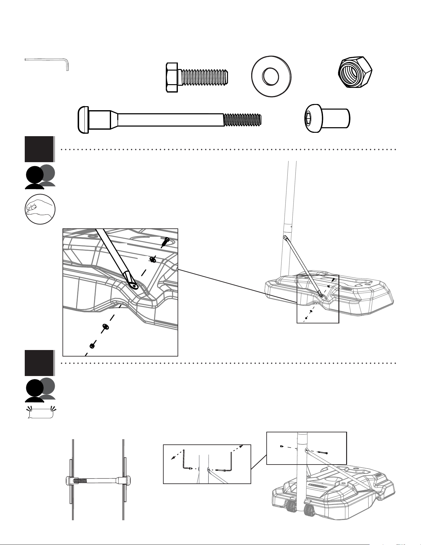
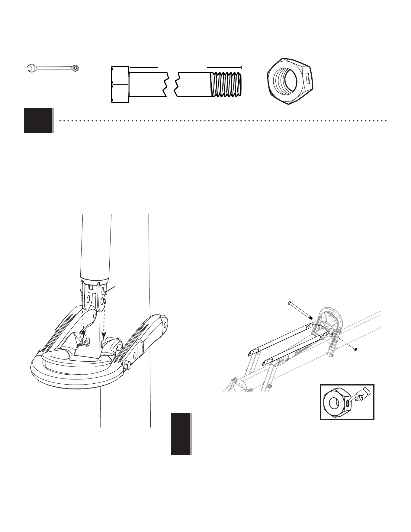
• While a second adult holds the pole upright, attach a pole brace (ALI) to the base as
indicated. Tighten only by hand at this time. Repeat this step for the second pole brace on the
other side of the pole and base.
• Pendant qu’un deuxième adulte tient le poteau a la verticale, attacher un support
de poteau (ALI) a la base comme indiqué. Serrer seulement a la main en ce moment. Répéter
cette étape pour le deuxième support de poteau sur l’autre côté du poteau et de la base.
• Mientras un segundo adulto sostiene el poste en posición vertical, sujetar un
soporrte de poste (ALI) a la base come se indica. Apretar sólo a mano en este momento.
Repetir este paso para el segundo soporte de poste en el otro lado del poste y de la base.
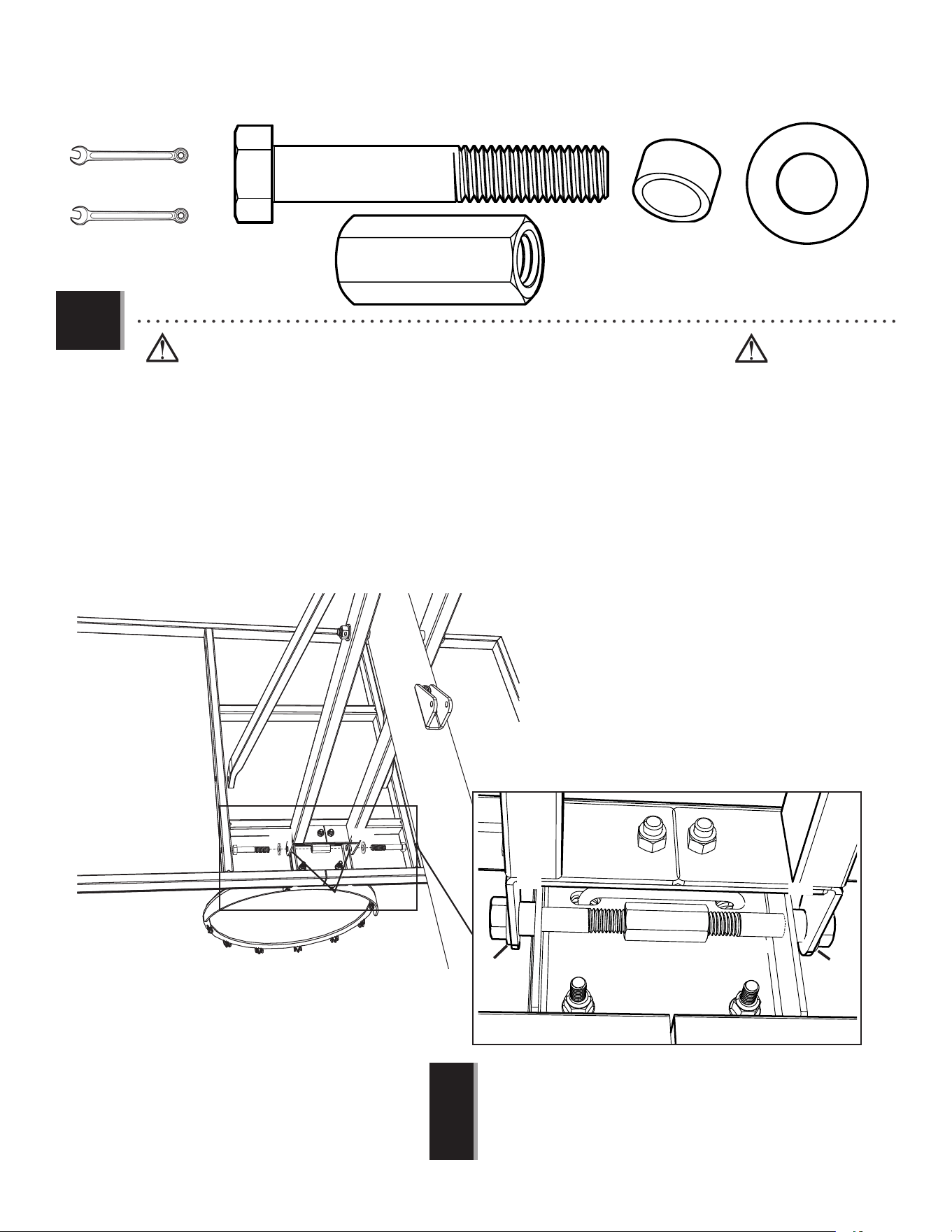
• Align the holes in the braces with those in the pole and secure the braces to the pole using the hardware indicated. Note the
bolt (DRZ) does not go all the way through the pole; the barrel nut (BTS) connects to it inside the pole. DO NOT completely tighten at this time.
• Aligner les trous dans les supports avec ceux dans le poteau et fi xer les supports au poteau en utilisant la quincaillerie
indiquée. Notar que le boulon (DRZ) ne traverse pas complètement le poteau ; l’écrou à manchon (BTS) s’y connecte à l’intérieur du poteau. NE
PAS serrer complètement en ce moment.
• Alinear los orifi cio en los soportes con ellos en el poste y fi jar los soportes al poste usando el herraje indicado. Observar que el
perno (DRZ) no atraviesa por completo el poste; la tuerca de acoplamiento (BTS) se conecta a ello dentro del poste.
• NO apretar por completo en este momento.
AAE (x2)
ABD (x4)
AAO (x2)
AAO
ABD
ABD
ALI
ALI
AAE
BTS (x1)
DRZ (x1)
DRZ
BTS
“$#@*%!”
THIS STEP CAN BE DIFFICULT
DSA
BTS
EEO (x2)
15
TOOLS AND HARDWARE REQUIRED / OUTILS ET QUINCAILLERIE REQUIS / INSTRUMENTAL Y HERRAJE REQUERIDOS
SECTION 2 (CONTINUED) / SECTION 2 (SUITE) / SECCIÓN 2 (CONTINUACIÓN)
2.7
2.8
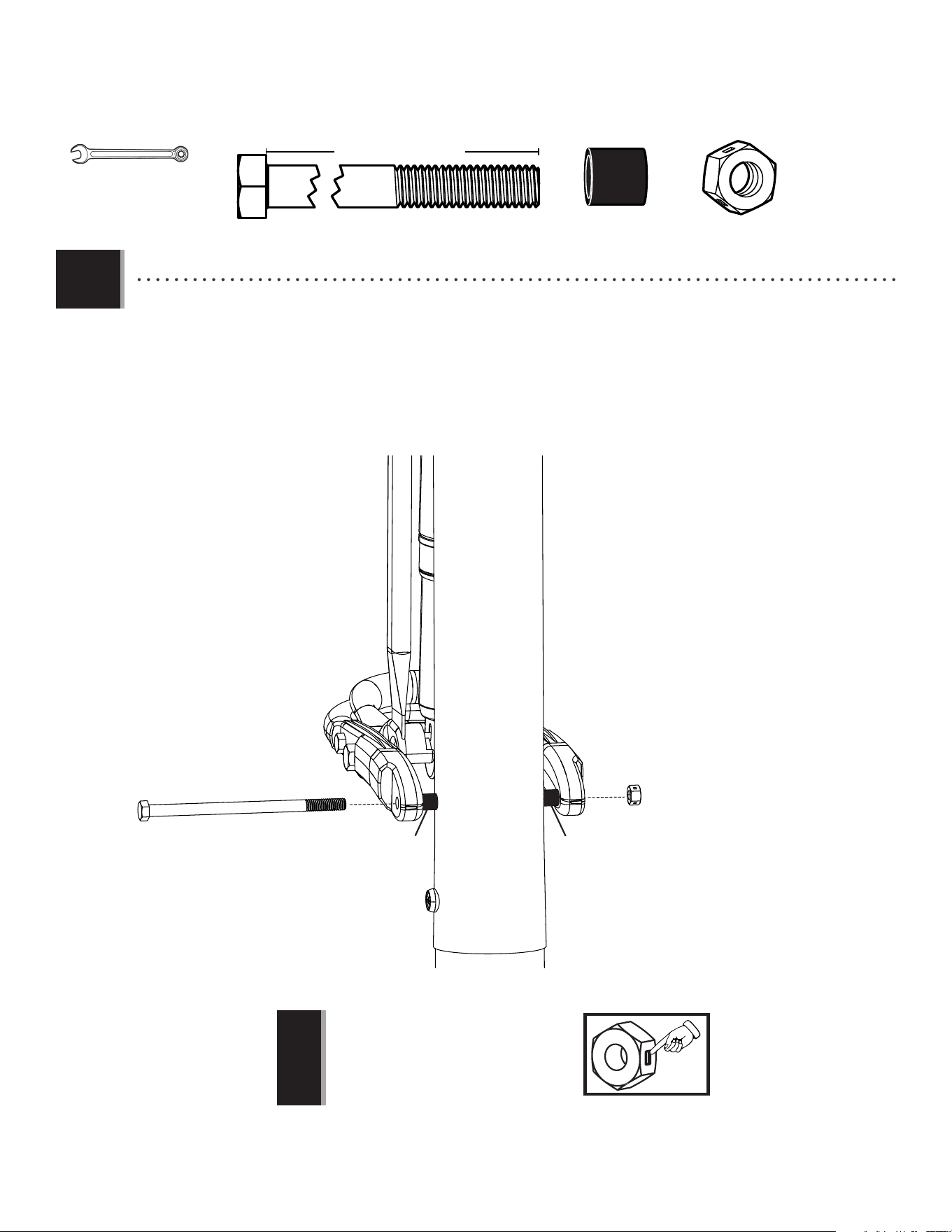
• Lay the system down and keep it down until instructed otherwise. Securely tighten the hardware
indicated. DO NOT overtighten.
• Poser le système sur le sol et le maintenir jusqu’à instruction contraire. Bien serrer la quincaillerie
indiquée. NE PAS trop serrer.
• Colocar el sistema en el suelo y guardarlo así hasta que se le indique lo contrario. Apretar bien el
herraje indicado. NO apretar demasiado.
• Now, securely tighten the hardware from step 2.6.
• Maintenant, bien serrer la quincaillerie de l’étape 2.6.
• Ahora, apretar bien el herraje del paso 2.6.
1/2" (≈13 mm)
(x2)
EEO (x2)
16
3
BACKBOARD TO RIM ASSEMBLY / ASSEMBLAGE DU PANNEAU À L’ANNEAU / ENSAMBLAJE DEL TABLERO AL ARO
PARTS REQUIRED / PIÈCES REQUISES / PIEZAS REQUERIDAS
Metal parts / Pièces en métal / Piezas de metal
EAP (x2)
AAQ (x2)
ABK (x4)
AAV (x2)
ADR (x4)
AJW (x2)
APZ (x1)
AOW (x1)
APY (x1)
ABQ (x1)
HARDWARE REQUIRED / QUINCAILLERIE REQUISE / HERRAJE REQUERIDO
BCS
ALX (x1)
AJI (x1)
ALD (x1)
AMA (x1)
BGR (x1)
TOOLS REQUIRED / OUTILS REQUIS / HERRAMIENTAS REQUERIDAS
1/2" (≈13 mm)
1/2” (≈13 mm)
(x2)
1717
TOOLS AND HARDWARE REQUIRED / OUTILS ET QUINCAILLERIE REQUIS / HERRAMIENTAS Y HERRAJE REQUERIDOS
SECTION 3 (CONTINUED) / SECTION 3 (SUITE) / SECCIÓN 3 (CONTINUACIÓN)
3.1
EAP (x2)
APY (x1)
AAQ (x1)
ABQ (x1)
1/2" (≈13 mm)
• Insert two carriage bolts (EAP) through the rim pivot bracket (APY) as shown.
• Insérez deux boulons de carrosserie (EAP) à travers le support pivotant de l’anneau
(APY) comme illustré.
• Inserte dos pernos de cuello cuadrado (EAP) por el soporte giratorio del aro (APY)
como se muestra.
EAP
EAP
APY
3.2
• Use the 1/2" (≈13 mm) socket head from the socket head wrench to press one push
nut (AAQ) onto one end of the axle (ABQ).
• Utilisez la douille de 1/2 po (≈13 mm) de la clé à douille pour pousser une rondelle
de retenue (AAQ) sur une extrémité de l’essieu (ABQ).
• Use el cubo de 1/2” (≈13 mm) de la llave de cubo para presionar una rondana de
fi jación rápida (AAQ) sur un extremo del eje (ABQ).
• The push nut should rest about 1/4" from the end of the
axle. If the push nut slips on too far, continue sliding it to
the other end of the axle to remove it and try again.
• La rondelle de retunue doit rester environ 6,35 mm (1/4 po)
de l’extrémité de l’essieu. Si la rondelle de retenue glisse
plus de cela, faites-le glisser de l’autre extrémité de l’essieu
et commencez de nouveau.
• La rondana de fi jación rápida debe quedarse 6,35 mm
(1/4") del extremo del eje. Si la rondana de fi jación rápida
se resbala más que eso, resbálela del otro extremo del eje y
empiece de nuevo.
AAQ
ABQ
1/2" (≈13 mm) socket head
1/2 po (≈13 mm) de la clé à douille
1/2" (≈13 mm) de la llave de cubo
!
• If you have trouble with this section, scan the code below to view a video on on its assembly.
• En cas d’avoir des problèmes avec cette section, scannez le QR code en dessous pour voir un vidéo de l’assemblage.
• En caso de tener problemas con esta sección, escanee el código QR debajo para ver un video del ensamblaje.
• http://go.lifetime.com/71522powerlift-section3
!
18
TOOLS AND HARDWARE REQUIRED / OUTILS ET QUINCAILLERIE REQUIS / HERRAMIENTAS Y HERRAJE REQUERIDOS
SECTION 3 (CONTINUED) / SECTION 3 (SUITE) / SECCIÓN 3 (CONTINUACIÓN)
3.3
3.4
• Slide the end of the axle (ABQ) through the rim (ALX) and the rim pivot bracket (APY). Press the push nut (AAQ) onto
the end of the axle. Use the 1/2" (≈13 mm) socket head to secure the push nut if needed.
• Faites glisser l’extrémité de l’essieu (ABQ) à travers l’anneau (ALX) et le support pivotant de l’anneau (APY). Poussez la
rondelle de retenue (AAQ) sur l’extrémité de l’essieu. Si besoin, employez la douille de 1/2 po (13 mm) pour fi xer
la rondelle de retenue en place.
• Deslice el extremo del eje (ABQ) por el aro (ALX) y el soporte giratorio del aro (APY). Presione la rondana de fi jación
rápida (AAQ) sobre el extremo del eje. Si hace falta, use el cubo de 1/2" (13 mm) para fi jar la rondana de fi jación
rápida en su lugar.
ABK (x2)
AAQ (x1)
1/2" (≈13mm)
APY
ALX
ABQ
ABQ
AAQ
APY
1/2"
(≈13mm)
• Connect the rim (ALX) and plastic guard (ALD) to the backboard (AJI) with the hardware shown.
• Attachez l’anneau (ALX) et le protection en plastique (ALD) au panneau (AJI) en utilisant la quincaillerie illustrée.
• Sujete el aro (ALX) y la protección de plastico (ALD) al tablero (AJI) usando el herraje indicado.
ABK
ABK
ALD
AJI
(x2)
19
TOOLS AND HARDWARE REQUIRED / OUTILS ET QUINCAILLERIE REQUIS / HERRAMIENTAS Y HERRAJE REQUERIDOS
SECTION 3 (CONTINUED) / SECTION 3 (SUITE) / SECCIÓN 3 (CONTINUACIÓN)
APZ
BGR
AJI
3.6
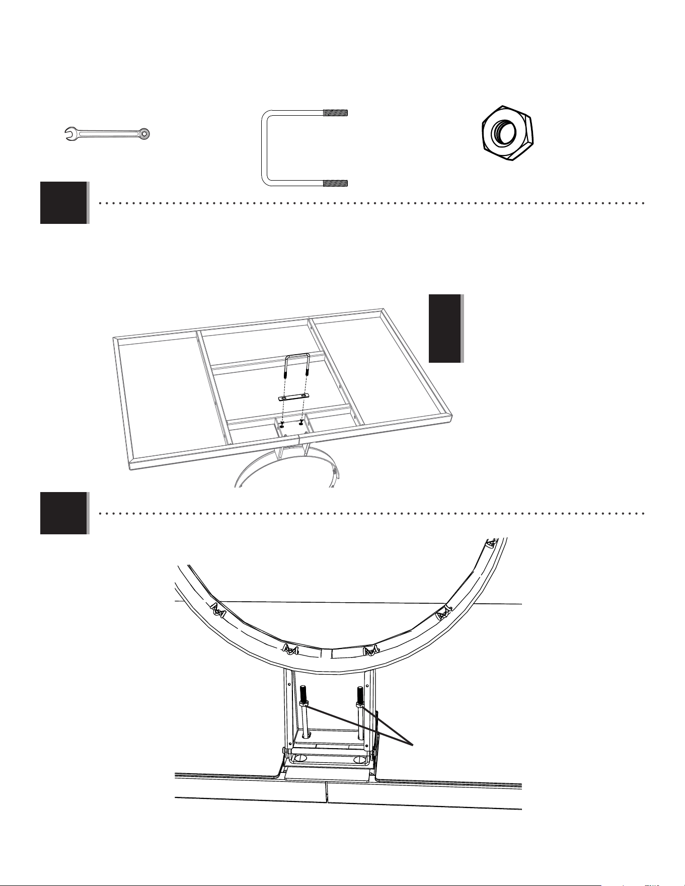
• Thread the jam nuts (AAV) all the way down on the U-bolt (APZ) as shown.
• Serrez bien les contre-écrous (AAV) au boulon en « U » (APZ).
• Apriete por completo las contratuercas de (AAV) en el perno en «U» (APZ).
AAV
APZ
APZ (x1)
AAV (x2)
1/2" (≈13 mm)
• Lay the backboard (AJI) on a table or bench. Insert the U-bolt (APZ) through the upper part of the opening on the backside of
the backboard (AJI) as shown.
• Mettez le panneau (AJI) sur une table ou un banc. Insérez le boulon en « U » (APZ) à travers le partie supérieure du trou au
verso du panneau (AJI) comme illustré.
• Coloque el tablero (AJI) sobre una mesa o un banco. Inserte el perno en «U» (APZ) por la parte superior del hueco en la parte
trasera del tablero (AJI) como se muestra.
• • Insert the U-bolt (APZ) through the top holes of Insert the U-bolt (APZ) through the top holes of
the backboard and the rim.the backboard and the rim.
• • Insérez le boulon en « U » (APZ) à travers le jeu Insérez le boulon en « U » (APZ) à travers le jeu
supérieur des trous du panneau et de l’anneau.supérieur des trous du panneau et de l’anneau.
• • Inserte el perno em«U» (APZ) a través de los Inserte el perno em«U» (APZ) a través de los
agujeros superiores del tablero y del aro.agujeros superiores del tablero y del aro.
!
!
3.5
20
TOOLS AND HARDWARE REQUIRED / OUTILS ET QUINCAILLERIE REQUIS / HERRAMIENTAS Y HERRAJE REQUERIDOS
SECTION 3 (CONTINUED) / SECTION 3 (SUITE) / SECCIÓN 3 (CONTINUACIÓN)
3.7
ADR (x4)
ABK (x2)
AJW (x2)
AOW (x1)
1/2" (≈13 mm)
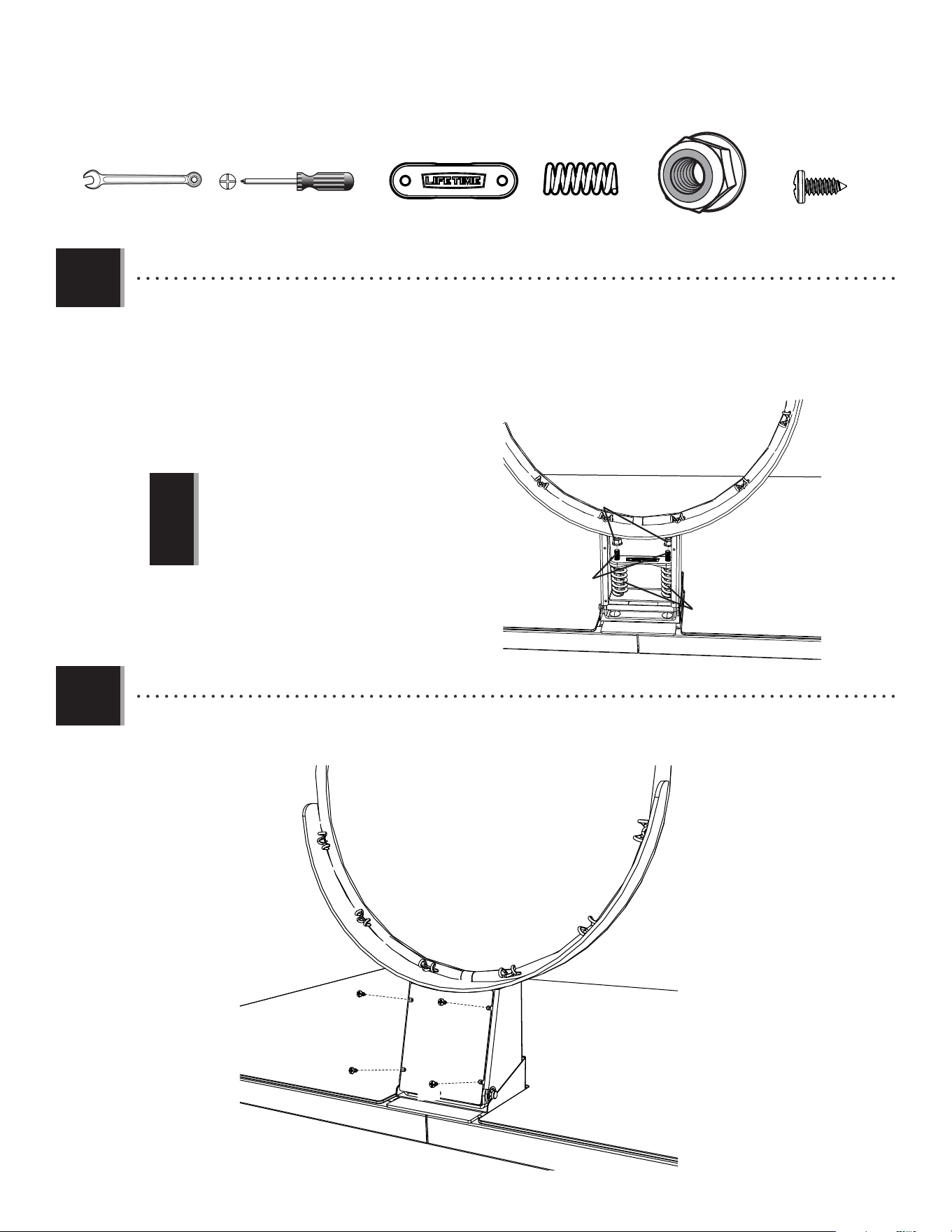
• Slide the compression springs (AJW) onto the U-bolt (APZ), and place the spring retainer plate (AOW) over the compression
springs. Tighten the nylock fl ange nuts (ABK) until the rim (ALX) does not wobble.
• Glissez les ressorts de pression (AJW) sur le boulon en « U » (APZ), et placez the plaque de retenue du ressort (AOW) sur les
ressorts de pression. Serrez bien les écrous à bride en nylon (ABK) jusqu’à ce que l’anneau (ALX) n’est pas branlant.
• Deslice los resortes de compresión (AJW) sobre el perno en «U» (APZ), y coloque la placa retenedor del resorte (AOW) sobre
los resortes de compresión. Apriete las tuercas de brida de nailon (ABK) hasta que no se bambolea el aro (ALX).
APZ
AJW
AOW
ABK
3.8
• Do not completely tighten the nuts in this step!
Tightening the nuts adjusts the rim tension.
• Ne pas serrer excessivement les écrous en « T » pour
que les écrous en caoutchouc se gonfl ent.
• No apriete demasiado las tuercas en «T» para que se
sobresalgan las tuercas de goma.
• Attach the rim cover plate (AMA) to the rim (ALX) with the hardware shown.
• Attachez bien la plaque protectrice des ressorts (AMA) à l’anneau (ALX) à l’aide de la quincaillerie indiquée.
• Sujete la placa protectora de los resortes (AMA) al aro (ALX) usando el herraje indicado.
ALX
ADR
ADR
ADR
ADR
AMA
!
21
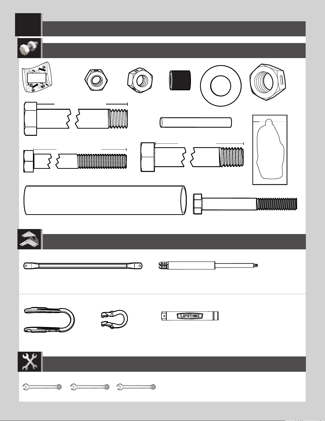
HARDWARE REQUIRED / QUINCAILLERIE REQUISE / HERRAJE REQUERIDO
BACKBOARD-TO-POLE ASSEMBLY / ASSEMBLAGE DU PANNEAU AU POTEAU / ENSAMBLAJE DEL TABLERO AL POSTE
4
BCR
AAD (x1)
7 1/16 in/po (≈18cm)
AAX (x4)
AQB (x2)
AAN (x2)
ABP (x6)
AOR (x6)
AQC (x2)
ANK (x4)
AQD (x1)
5 in/po (≈13cm)
ANP (x1)
ANQ (x2)
ANU (x2)
ANS (x8)
PARTS REQUIRED / PIÈCES REQUISES / PIEZAS REQUERIDAS
ALM (x1)
BGO (x2)
BGP (x2)
BLC (x1)
TOOLS REQUIRED / OUTILS REQUIS / INSTRUMENTAL REQUERIDO
3/4" (≈19 mm)
1/2" (≈13 mm)
1/2" (≈13 mm)
11/16" (≈18 mm)
3/4" (≈19 mm)
(x2)
(x1)
(x1)
(x1)
(x1)
22
TOOLS AND HARDWARE REQUIRED / OUTILS ET QUINCAILLERIES REQUIS / INSTRUMENTAL Y HERRAJE REQUERIDOS
SECTION 4 (CONTINUED) / SECTION 4 (SUITE) / SECCIÓN 4 (CONTINUACIÓN)
4.2
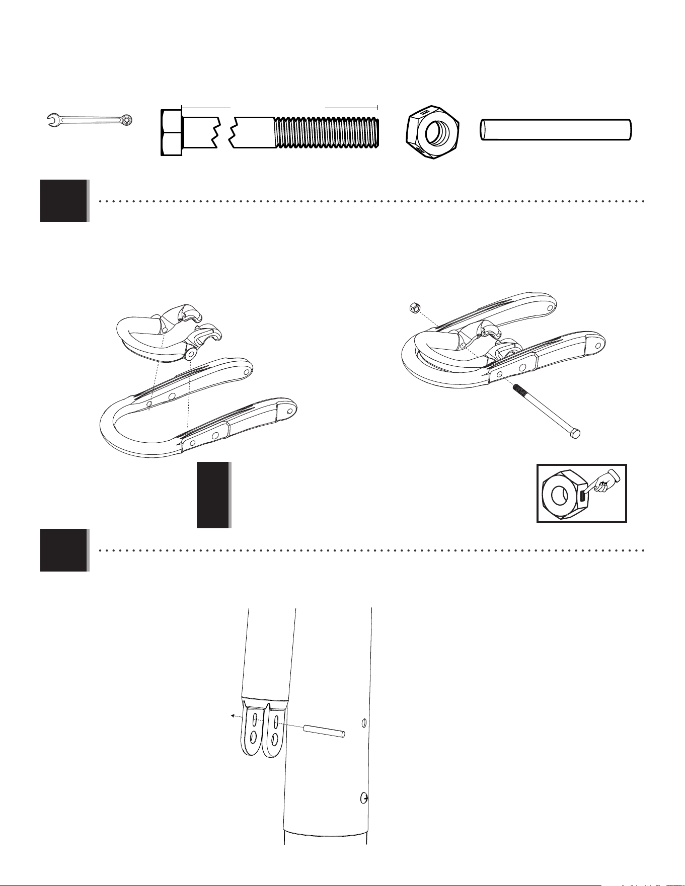
• Secure the lower extension arms (BGP) together with the hardware shown. Use a 1/2" (13 mm) socket wrench to screw the thread-
cutting bolts (AQB) through the lower extension arms and the tie plate (BLC).
• Bien attacher les bras de rallonge inférieurs (BGP) à l’aide de la quincaillerie indiquée. Employer une clé à douilles de 1/2 po (≈13
mm) pour visser les boulons auto-taraudeurs (AQB) à travers les bras de rallonge inférieurs et le support (BLC).
• Sujetar bien los brazos de extensión inferiores (BGP) usando el herraje indicado. Usar una llave de 1/2 in. (≈13 mm) para atornillar los
pernos autoroscantes (AQB) por los brazos de extensión inferiores y el soporte (BLC).
AQB
AQB
AAN
BGP
BGP
BLC
AQB (x2)
AAN (x2)
1/2" (≈13 mm)
1/2" (≈13 mm)
4.1
BLC
BLC
BGP
BGP
• Insert one end of the tie plate (BLC) into the slot on the lower extension arm (BGP). Then insert the opposite end of the tie plate (BLC) into the slot
on the other lower extension arm (BGP) as indicated.
• Insérer une extrémité du support (BLC) dans la fente sur le bras de rallonge inférieur (BGP). Ensuite, insérer l’extrémité opposée du support (BLC)
dans la fente sur l’autre bras de rallonge inférieur (BGP) comme indiqué.
• Insertar un extremo del soporte (BLC) en la ranura en el brazo de extensión inferior (BGP). Entonces, insertar el extremo opuesto del soporte (BLC)
en la ranura del otro brazo de extensión inferior (BGP) como se indica.
WARNING
Do not overtighten the cap nut. If the end of
the bolt breaks through the plastic cap, call our
Customer Service Department. Exposed threads
on the end of the bolt may cause serious injuries.
AVERTISSEMENT
Ne pas serrer excessivement l’écrou à chape.
Si l’extrémité du boulon passe au travers du
chapeau en plastique, veiller à appeler le service
client. Si le filetage à l’extrémité du boulon est
exposé il peut causer des blessures graves.
ADVERTENCIA
No apretar demasiado la tuerca ciega. Si el
extremo del perno extiende por el plástico, llamar
a nuestro Departamento de servicios a clientes.
Hilos expuestos podrían causar lesiones graves.
!
!
!
!
!
!
• If you have trouble with this section, scan the code below to view a video on on its assembly.
• En cas d’avoir des problèmes avec cette section, scanner le QR code en dessous pour voir un vidéo de l’assemblage.
• En caso de tener problemas con esta sección, escanear el código QR debajo para ver un video del ensamblaje.
• http://go.lifetime.com/71522powerlift-section4
!
23
TOOLS AND HARDWARE REQUIRED / OUTILS ET QUINCAILLERIES REQUIS / INSTRUMENTAL Y HERRAJE REQUERIDOS
SECTION 4 (CONTINUED) / SECTION 4 (SUITE) / SECCIÓN 4 (CONTINUACIÓN)
4.3
• Insert the extension arm caps (AQC) into the ends of the lower extension arms (BGP) as indicated.
• Insérer les capuchons des bras de rallonge (AQC) dans les extrémités des bras de rallonge inférieurs (BGP) comme indiqué.
• Insertar los tapones para los brazos de extensión (AQC) en los extremos de los brazos de extensión inferiores (BGP) como se indica.
AQC (x2)
1/2" (≈13 mm)
AQC
AQC
1/2"
(≈13 mm)
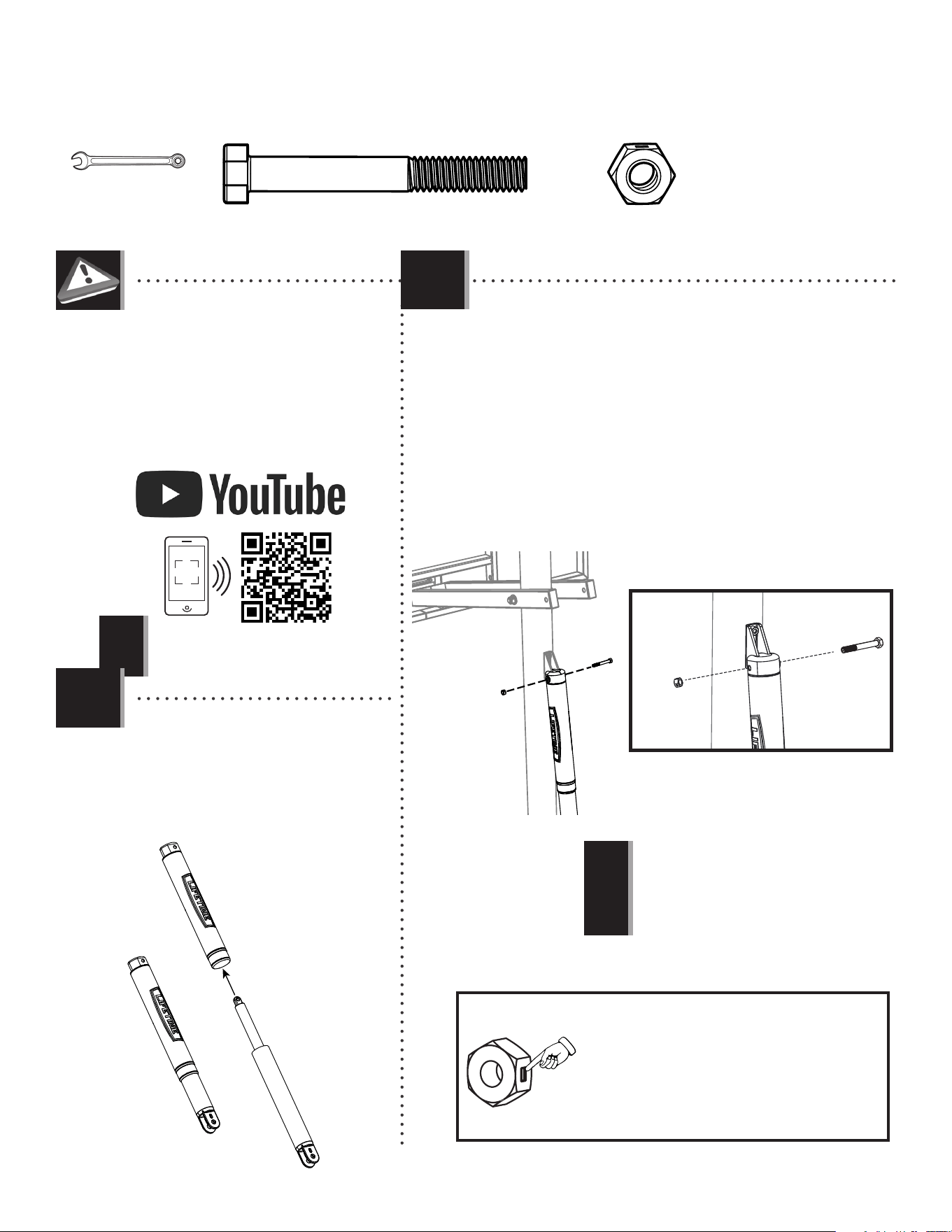
• Tighten the centerlock nut (AAX) until it is fl ush with the end of the bolt.
• Serrer l’écrou de blocage central de (AAX) jusqu’à ce qu’il soit au ras de
l’extrémité du boulon.
• Apretar la tuerca de bloqueo central (AAX) hasta que esté a ras del extremo
del perno.
!
AAD
AOR
AOR
AAX
ABP
ALH
• A nut with this marking will require some e ort to thread onto a bolt.
See page 4 for details.
• Un écrou avec ce marquage requerra plus d’e ort pour le serrer. Voir
la page 4 pour plus de détails.
• Una tuerca con esta marca requerirá un poco de esfuerzo para
apretarlo. Ver la página 4 para ver más detalles.
4.6
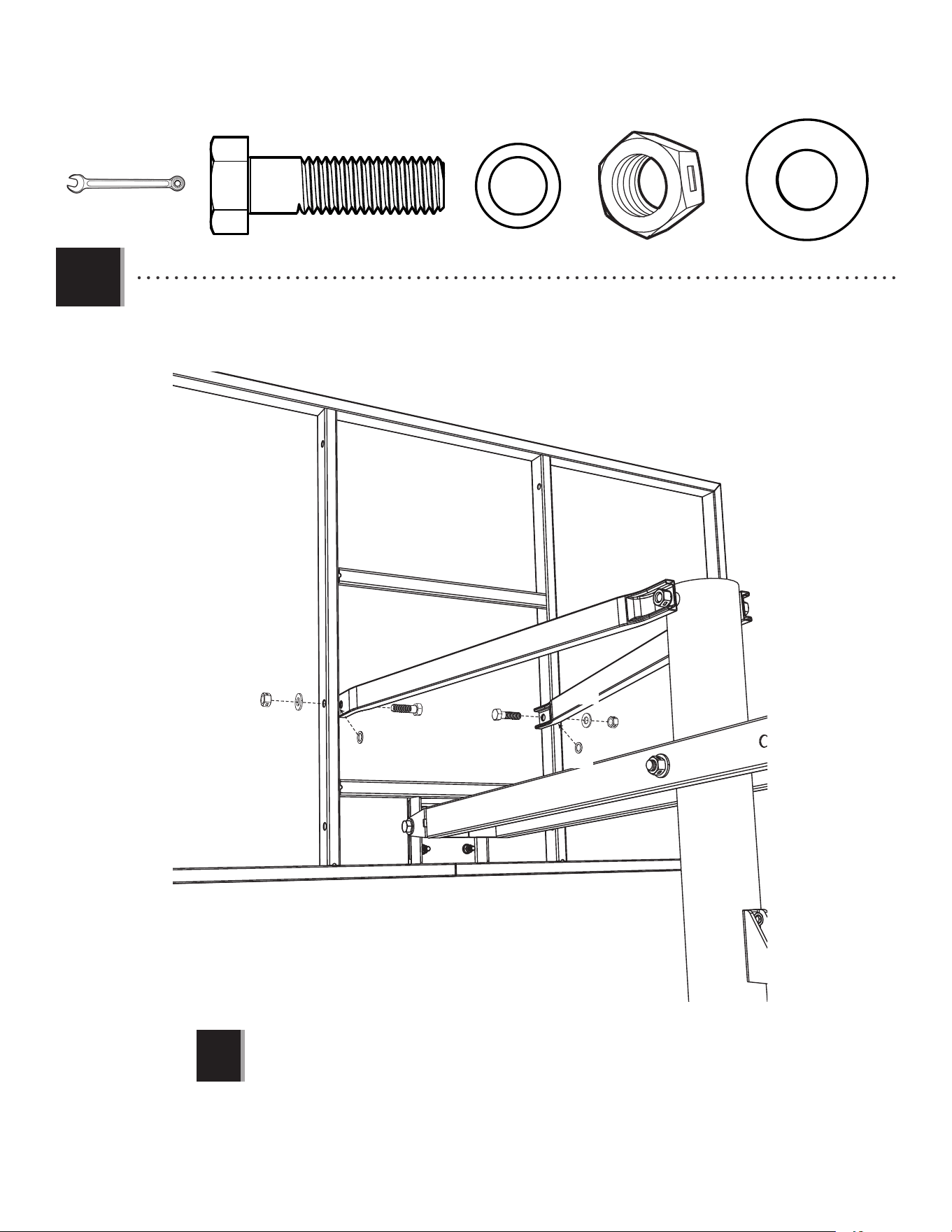
• Secure the top pole (ALH) to the lower extension arms (BGP) using the hardware indicated.
• Bien attacher le poteau supérieur (ALH) aux bras de rallonge inférieurs (BGP) à l’aide de la quincaillerie
indiquée.
• Sujetar bien el poste superior (ALH) a los brazos de extensión inferiores (BGP) usando el herraje
indicado.
4.4
7 1/16 in/po (≈18cm)
AAD (x1)
AAX (x1)
ABP (x2)
AOR (x2)
3/4"
(≈19 mm)
(x2)
24
TOOLS AND HARDWARE REQUIRED / OUTILS ET QUINCAILLERIES REQUIS / INSTRUMENTAL Y HERRAJE REQUERIDOS
SECTION 4 (CONTINUED) / SECTION 4 (SUITE) / SECCIÓN 4 (CONTINUACIÓN)
• Tighten the 1/2" centerlock nut (AAX) until it is fl ush with the end of the bolt.
• Serrer l’écrou de blocage central de 1/2" po (AAX) jusqu’à ce qu’il soit au ras
de l’extrémité du boulon.
• Apretar la tuerca de bloqueo central de 1/2" in. (AAX) hasta que esté a ras del
extremo del perno.
4.5
• Attach the upper extension arms (BGO) to the top pole (ALH) using the hardware indicated.
• Attacher les bras de rallonge supérieurs (BGO) au poteau supérieur (ALH) à l’aide de la quincaillerie indiquée.
• Sujetar los brazos de extensión superiores (BGO) al poste superior (ALH) usando el herraje indicado.
AQD (x1)
5 in/po (≈13cm)
AAX (x1)
ABP (x2)
3/4"
(≈19 mm)
ANK (x2)
3/4" (≈19 mm)
AQD
AAX
BGO
ANK
ABP
ABP
ANK
BGO
ALH
!

i
PARTS IDENTIFIER /IDENTIFICATEUR DE PIÈCES / IDENTIFICADOR DE PIEZAS
This page intentionally left blank
Cette page est intentionnellement laissée en blanc
Esta página ha sido dejada en blanco intencionalmente
Detach this yellow section for use as a quick reference / Détacher cette section jaune pour l’utiliser comme un référence rapide / Separar esta sección amarilla para usarla como una referencia rápida
ii
PARTS IDENTIFIER / IDENTIFICATEUR DE PIÈCES / IDENTIFICADOR DE PIEZAS
Metal part / Pièce en métal / Pieza de metal
ALL (x1)
AJI (x1)
AJD (x1)
ALI (x2)
ALX (x1)
AMA (x1)
BGR (x1)
BGO (x2)
BGP (x2)
BLC (x1)
ALS (x2)
Warning Sticker
Autocollant d’avertissement
Etiqueta adhesiva de advertencia
ALH (x1)
ALF (x1)
ALE (x1)
Detach this yellow section for use as a quick reference / Détacher cette section jaune pour l’utiliser comme un référence rapide / Separar esta sección amarilla para usarla como una referencia rápida
iii
PARTS IDENTIFIER / IDENTIFICATEUR DE PIÈCES / IDENTIFICADOR DE PIEZAS
Plastic Parts / Pièces en plastique / Piezas de plástico
HARDWARE REQUIRED / QUINCAILLERIE REQUISE / HERRAJE REQUERIDO
BCO BCS BCTBCR
AKP (x1)
1109 02 5
10’
9’6”
9’
8’6”
7’6”
8’
AKZ (x1)
ALM (x1)
ALD (x1)
BCQ
AJM (x1)
AKF (x1)
AKG (x1)
AKH (x1)
BCU
BAA (x1)
AJQ (x1)
BAB (x1)
AKI (x1)
AMN (x1)
Detach this yellow section for use as a quick reference / Détacher cette section jaune pour l’utiliser comme un référence rapide / Separar esta sección amarilla para usarla como una referencia rápida
FIQ (x1)
FIR (x1)
AEF (x2)
AMU (x2)

iv
PARTS IDENTIFIER / IDENTIFICATEUR DE PIÈCES / IDENTIFICADOR DE PIEZAS
This page intentionally left blank
Cette page est intentionnellement laissée en blanc
Esta página ha sido dejada en blanco intencionalmente
Detach this yellow section for use as a quick reference / Détacher cette section jaune pour l’utiliser comme un référence rapide / Separar esta sección amarilla para usarla como una referencia rápida
25
TOOLS AND HARDWARE REQUIRED / OUTILS ET QUINCAILLERIES REQUIS / INSTRUMENTAL Y HERRAJE REQUERIDOS
SECTION 4 (CONTINUED) / SECTION 4 (SUITE) / SECCIÓN 4 (CONTINUACIÓN)
4.6
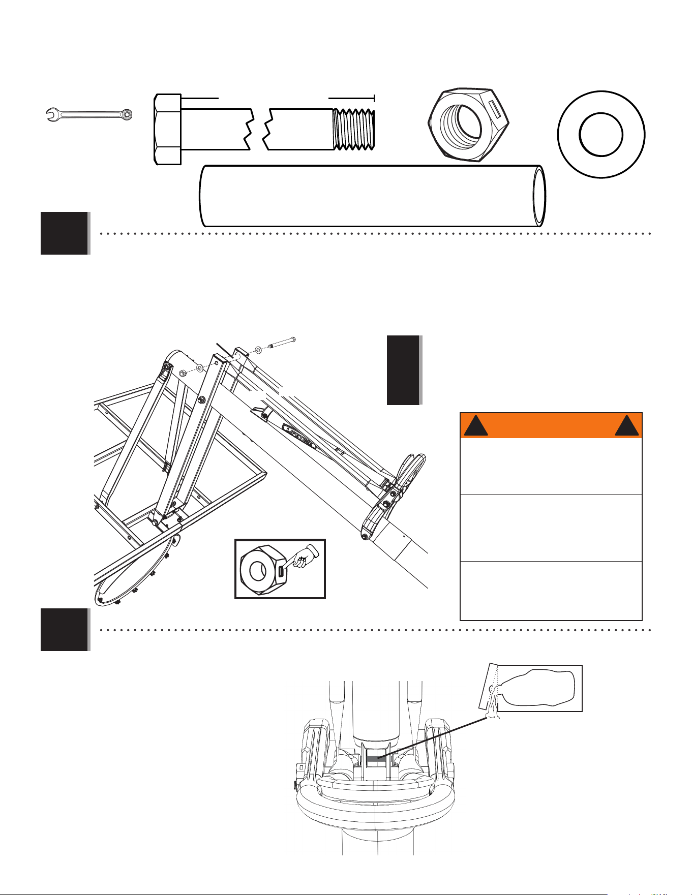
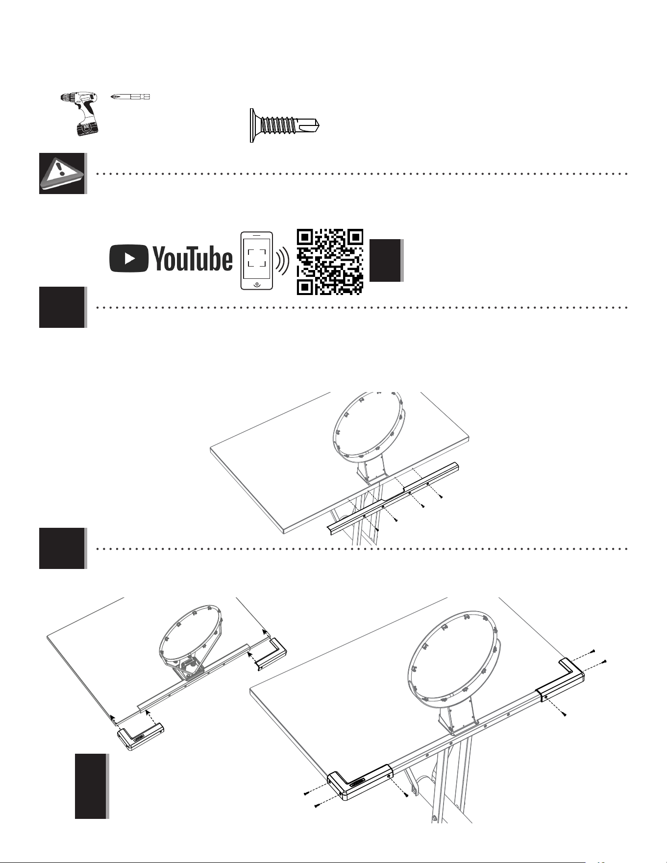
• Rest the rim on cardboard to prevent scratching. Then, secure the lower extension arms (BGP) to the backboard (AJI) with
the hardware shown. Screw the nut coupler (ANP) onto one of the hex bolts (ANQ), then onto the other. Center the coupler
between the two bolts as indicated.
• Placer l’anneau sur un morceau de carton pour le protéger contre les rayures. Ensuite, attacher les bras de rallonge
inférieurs (BGP) au panneau (AJI) à l’aide de la quincaillerie indiquée. Visser le coupleur (ANP) sur un boulon à tête hexagonale
(ANQ), ensuite sur l’autre. Centrer le coupleur entre les deux boulons comme indiqué.
• Colocar el aro sobre un pedazo de cartón para evitar rayarlo. Entonces, sujetar los brazos de extensión inferiores (BGP) al
tablero (AJI) usando el herraje indicado. Atornillar el acoplador (ANP) sobre uno de los pernos de cabeza hexagonal (ANQ), entonces
sobre el otro. Centrar el acoplador entre los pernos como se indica.
• Ensure the poly spacers (ABP) are positioned between the lower extension arms
and the backboard and do not bulge.
• S’assurer que les pièces d’écartement en plastique (ABP) sont positionées entre
les bras de rallonge inférieurs et le panneau et que ne gonfl ent pas.
• Asegurarse de que los espaciadores de plástico (ABP) estén colocados entre los
brazos de extensión inferiores y el tablero y que no sobresalgan.
!
3/4" (≈19 mm)
ABP (x2)
AOR (x2)
ANP (x1)
ANQ (x2)
11/16" (≈18 mm)
CAUTION: HAVE ONE ADULT HOLD THE BACKBOARD IN PLACE UNTIL ASSEMBLY HAS BEEN COMPLETED!
CAUTION : UN ADULTE DOIT MAINTENIR LE PANNEAU EN PLACE AVANT QUE L’ASSEMBLAGE EST TERMINÉ !
CUIDADO: ¡UN ADULTO DEBE MANTENER EL TABLERO EN SU LUGAR HASTA FINALIZAR EL ENSAMBLE!
BGP
BGP
AJI
ANQ
ANQ
AOR
AOR
ANP
ABP
ANQ
ANQ
AOR
AOR
ANP
ABP
ABP
26
TOOLS AND HARDWARE REQUIRED / OUTILS ET QUINCAILLERIES REQUIS / INSTRUMENTAL Y HERRAJE REQUERIDOS
SECTION 4 (CONTINUED) / SECTION 4 (SUITE) / SECCIÓN 4 (CONTINUACIÓN)
4.7
• Attach the upper extension arms (BGO) to the backboard (AJI) with the hardware indicated.
• Attacher les bras de rallonge supérieurs (BGO) au panneau (AJI) à l’aide de la quincaillerie indiquée.
• Sujetar los brazos de extensión superiores (BGO) al tablero (AJI) usando el herraje indicado.
3/4"
(≈19 mm)
AAX (x2)
ANK (x2)
AOR (x2)
ANU (x2)
• Tighten the nut until it is fl ush with the end of the bolt.
• Serrer l’écrou jusqu’à ce qu’il soit au ras de l’extrémité du boulon.
• Apretar la tuerca hasta que esté a ras del extremo del perno.
!
AAX
AAX
AOR
AOR
ANK
ANK
ANU
ANU
BGO
BGO
(x2)
27
TOOLS AND HARDWARE REQUIRED / OUTILS ET QUINCAILLERIES REQUIS / INSTRUMENTAL Y HERRAJE REQUERIDOS
SECTION 4 (CONTINUED) / SECTION 4 (SUITE) / SECCIÓN 4 (CONTINUACIÓN)
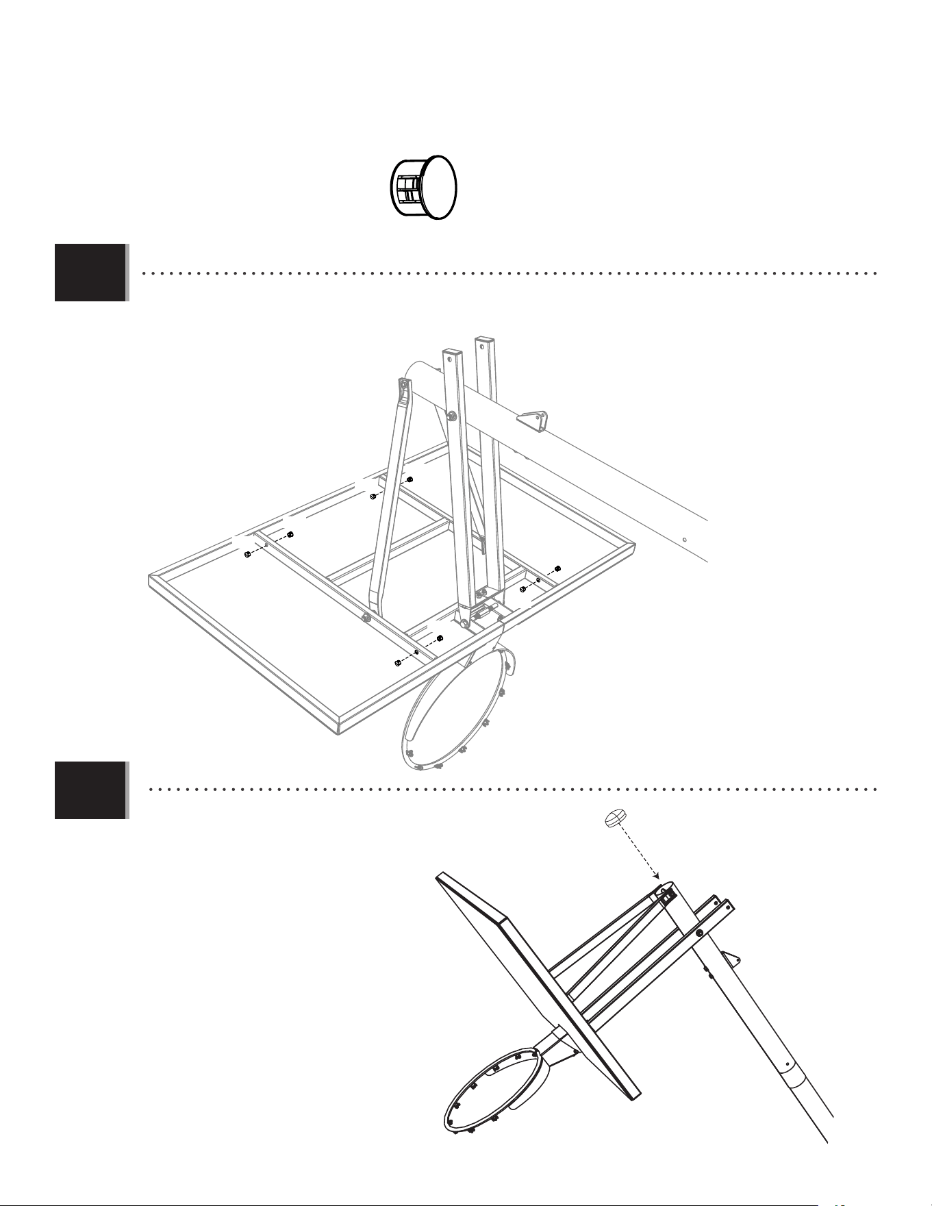
• Insert the nylon plugs (ANS) into the holes indicated on the metal frame of the backboard.
• Insérer les capuchons en nylon (ANS) dans les trous indiqués sur le structure en acier du panneau.
• Insertar los tapones de nylon (ANS) en los agujeros indicados en el armazón de acero del tablero.
• Insert the cap (ALM) into the top pole (ALH).
• Insérer le capuchon (ALM) dans le poteau supérieur (ALH).
• Insertar el tapón (ALM) en el poste superior (ALH).
ANS (x8)
ANS
ANS
ANS
ANS
ALM
ALH
4.8
4.9
ANS
ANS
ANS
ANS
28
7 1/16 in/po (≈18cm)
6 1/2 in/po (≈17cm)
ABM (x2)
PARTS REQUIRED / PIÈCES REQUISES / PIEZAS REQUERIDAS
HARDWARE REQUIRED / QUINCAILLERIE REQUISE / HERRAJE REQUERIDO
BCT
Metal part / Pièce en métal / Pieza de metal
AAD (x1)
TOOLS REQUIRED / OUTILS REQUIS / HERRAMIENTAS REQUERIDAS
(x2)(x2) (x2)
3/4"
(≈19 mm)
1/2" (≈13 mm)
9/16" (≈14 mm)
AQE (x1)
6 1/2 in/po (≈17cm)
AAX (x2)
ABB (x2)
BSG (x1)
ACX (x1)
ABA (x2)
AAW (x1)
AKH (x1)
AOR (x2)
HANDLE ASSEMBLY / ASSEMBLAGE DE LA POIGNÉE / ENSAMBLAJE DE LA MANIVELA
5
APR (x1)
Plastic parts / Pièces en plastique / Piezas de plástico
ALS (x2)
AKF (x1)
AKI (x1)
AMN (x1)
AKG (x1)
29
TOOLS AND HARDWARE REQUIRED / OUTILS ET QUINCAILLERIE REQUIS / INSTRUMENTAL Y HERRAJE REQUERIDOS
SECTION 5 (CONTINUED) / SECTION 5 (SUITE) / SECCIÓN 5 (CONTINUACIÓN)
• http://go.lifetime.com/71522powerlift-section5
!
• Align the holes in the gas spring cover (AKG) and the gas spring (AKF)
with the holes in the pole bracket (ALL), and attach the gas spring
assembly to the pole bracket with the hardware indicated.
• Aligner les trous dans le couvercle du piston à gaz (AKG) et le piston
à gaz (AKF) avec ceux dans le support du poteau (ALL), et attacher
l’ensemble du piston à gaz au support du poteau en
utilisant la quincaillerie indiquée.
• Alinear los agujeros en la cubierta del amortiguador de gas (AKG)
y el amortiguador de gas (AKF) con ellos en el soporte del poste (ALL), y
sujetar el conjunto del amortiguador de gas al soporte del
poste usando el herraje indicado.
5.1
ACX (x1)
BSG (x1)
(x2)
1/2"
(≈13 mm)
AKG
AKF
BSG
BSG
ACX
ACX
ALL
ALL
5.2
• Slide the gas spring cover (AKG) onto the gas
spring (AKF) as indicated.
• Faire glisser le couvercle du piston à gaz (AKG)
sur piston à gaz (AKF) comme indiqué.
• Deslizar la cubierta del amortiguador de gas
(AKG) sobre el amortiguador de gas (AKF) como
se indica.
!
• Tighten the centerlock nut (BSG) until it is fl ush
with the end of the bolt.
• Serrer l’écrou de blocage central (BSG) jusqu’à ce
qu’il soit au ras de l’extrémité du boulon.
• Apretar la tuerca de bloqueo central (BSG) hasta
que esté a ras del extremo del perno.
• A nut with this marking will require some e ort
to thread onto a bolt. See page 4 for details.
• Un écrou avec ce marquage requerra plus d’e ort
pour le serrer. Voir la page 4 pour plus de détails.
• Una tuerca con esta marca requerirá un poco de
esfuerzo para apretarlo. Ver la página 4 para ver
más detalles.
• If you have trouble with this section, scan
the code below to view a video on its
assembly.
• En cas d’avoir des problèmes avec cette
section, scanner le QR code en dessous
pour voir un vidéo de l’assemblage.
• En caso de tener problemas con esta
sección, escanear el código QR debajo
para ver un video del ensamblaje.
30
TOOLS AND HARDWARE REQUIRED / OUTILS ET QUINCAILLERIE REQUIS / INSTRUMENTAL Y HERRAJE REQUERIDOS
SECTION 5 (CONTINUED) / SECTION 5 (SUITE) / SECCIÓN 5 (CONTINUACIÓN)
• Position the trigger (AMN) inside of the handle (AKI) as shown, and secure the trigger to the handle with the hardware
shown. Only fi nger tighten the hardware for now.
• Placer la manette (AMN) dans la poignée (AKI), y l’assurer à la poignée à l’aide de la quincaillerie indiquée.
Ne serrer la quincaillerie qu’à la main en ce moment.
• Colocar el gatillo (AMN) dentro de la manivela (AKI). Asegurar el gatillo a la manivela con el herraje indica. Sólo apretar a mano
el herraje en este momento.
!
• Tighten the centerlock nut (ABB) until it is fl ush with the end of the bolt.
• Serrer l’écrou de blocage central (ABB) jusqu’à ce qu’il soit au ras de
l’extrémité du boulon.
• Apretar la tuerca de bloqueo central (ABB) hasta que esté a ras del extremo
del perno.
5.3
5.4
9/16" (≈14 mm)
ABA (x1)
ABB (x1)
6 1/2 in/po (≈17cm)
ABA
ABB
AMN
AKI
AQE
AKF
• Insert the release pin (AQE) through the gas spring (AKF).
• Insérer la broche de sécurité (AQE) a travers du ressort de gaz (AKF).
• Insertar el pasador de seguridad (AQE) a través del resorte de gas (AKF).
AQE (x1)
(x2)
31
TOOLS AND HARDWARE REQUIRED / OUTILS ET QUINCAILLERIE REQUIS / INSTRUMENTAL Y HERRAJE REQUERIDOS
SECTION 5 (CONTINUED) / SECTION 5 (SUITE) / SECCIÓN 5 (CONTINUACIÓN)
5.5
AAW (x1)
AAX (x1)
6 1/2 in/po (≈17cm)
AKI
AMN
AQE
AAW
AAX
ALS
ALS
• Slide the handle (AKI) under the gas spring (AKF) so that the release pin (AQE) rests in the channels of the trigger (AMN). Position the rear lifter
arms (ALS) between the handle and trigger, and secure with the hardware indicated.
• Faire glisser la poignée (AKI) dessous le ressort de gaz (AKF) pour que la broche de sécurité (AQE) reste dans les rainures de
la manette (AMN). Placer les bras d’élévation arrières (ALS) entre la manivelle et la manette, et les assurer à l’aide de la
quincaillerie indiquée.
• Deslizar la manija (AKI) debajo el resorte de gas (AKF) para que el pasador de seguridad (AQE) quede dentro de los canales del
gatillo (AMN). Colocar los brazos de elevación traseros (ALS) dentro de la manija y del gatillo, y asegurarlos usando el herraje
indicado.
!
• Tighten the centerlock nut (AAX) until it is fl ush
with the end of the bolt.
• Serrer l’écrou de blocage central (AAX) jusqu’à ce
qu’il soit au ras de l’extrémité du boulon.
• Apretar la tuerca de bloqueo central (AAX) hasta
que esté a ras del extremo del perno.
AKF
3/4" (≈19 mm)
(x2)
32
TOOLS AND HARDWARE REQUIRED / OUTILS ET QUINCAILLERIE REQUIS / INSTRUMENTAL Y HERRAJE REQUERIDOS
SECTION 5 (CONTINUED) / SECTION 5 (SUITE) / SECCIÓN 5 (CONTINUACIÓN)
6 1/2 in/po (≈17cm)
5.6
ABA (x1)
ABB (x1)
ABM (x2)
ABA
ABB
ABM
ABM
AKI
ALF
• Secure the handle (AKI) to the middle pole (ALF) with the hardware shown. Ensure to place the spacers (ABM) between the
handle assembly and the middle pole as shown.
• Assurer la manivelle (AKI) à la section intermédiaire du poteau (ALF) à l’aide de la quincaillerie indiquée. S’assurer de insérer
les pièces d’écartement (ABM) entre l’ensemble de la manivelle et la section intermédiaire du poteau comme illustré.
• Sujetar la manivela (AKI) al poste intermedio (ALF) usando el herraje indicado. Asegurarse de insertar los espaciadores (ABM)
entre el conjunto de la manivela y el poste intermedio como se muestra.
!
• Tighten the centerlock nut (ABB) until it is fl ush with
the end of the bolt.
• Serrer l’écrou de blocage central (ABB) jusqu’à ce
qu’il soit au ras de l’extrémité du boulon.
• Apretar la tuerca de bloqueo central (ABB) hasta que
esté a ras del extremo del perno.
9/16" (≈14 mm)
(x2)
33
TOOLS AND HARDWARE REQUIRED / OUTILS ET QUINCAILLERIE REQUIS / INSTRUMENTAL Y HERRAJE REQUERIDOS
SECTION 5 (CONTINUED) / SECTION 5 (SUITE) / SECCIÓN 5 (CONTINUACIÓN)
7 1/16 in/po (≈18cm)
AAX (x1)
AAD (x1)
APR
AAX
ALS
AAD
ALS
AKH
AQE
5.7
5.8
• Apply grease from the grease packet (AKH) on to the release pin (AQE).
• Appliquer la graisse du paquet de graisse (AKH) sur l’axe de sécurité (AQE).
• Engrasar el pasador de seguridad (AQE) usando el paquete de grasa (AKH).
APR (x1)
• Connect the rear lifter arms (ALS) to the inside of the lower extension arms (BGP) with the hardware shown. Place a spacer (APR)
between the rear lifter arms as indicated.
• Attacher les bras de levage arrières (ALS) à l’intérieur des bras d’extension inférieurs (BGP) en utilisant la quincaillerie
indiquée. Insérer une pièce d’écartement (APR) entre les bras de levage arrières comme indiqué.
• Conectar los brazos elevadores traseros (ALS) al interior de los brazos de extensión inferiores (BGP) usando el herraje indicado.
Insertar un espaciador (APR) entre los brazos elevadores traseros como se indica.
!
• Tighten the centerlock nut (AAX) until it is fl ush with the end
of the bolt.
• Serrer l’écrou de blocage central (AAX) jusqu’à ce qu’il soit
au ras de l’extrémité du boulon.
• Apretar la tuerca de bloqueo central (AAX) hasta que esté a
ras del extremo del perno.
3/4" (≈19 mm)
(x2)
AOR (x2)
AOR
AOR
The handle mechanism is designed to lift
only the weight of the backboard and rim.
Do not hang anything from the handle, rim,
backboard, or lifter arms as this will damage
the system and void the warranty.
!
!
El mecanismo de la manija está diseñado de
soportar sólo el peso del tablero y el aro. No
suspender nada de la manija, aro, tablero, o
los brazos de elevación, el cual podría dañar
la unidad y anular la garantía.
Le mécanisme de la manivelle à été conçu
de supporter seulement le poids du panneau
et de l’anneau. Ne suspendre rien de la
manivelle, l’anneau, le panneau, ou les bras
d’élévation, lequel peut endommager le
système et annuler la garantie.
WARNING / AVERTISSEMENT
ADVERTENCIA
34
Plastic parts / Pièces en plastique / Piezas de plástico
TOOLS REQUIRED / OUTILS REQUIS / HERRAMIENTAS REQUERIDAS
PARTS REQUIRED / PIÈCES REQUISES / PIEZAS REQUERIDAS
HARDWARE REQUIRED / QUINCAILLERIE REQUISE / HERRAJE REQUERIDO
FINAL ASSEMBLY / ASSEMBLAGE FINAL / ENSAMBLAJE FINAL
6
AKZ (x1)
(x1) (x1) (x1)
325 lb (≈147kg)
ADP (x10)
BCU
AKP (x1)
1109 02 5
10’
9’6”
9’
8’6”
7’6”
8’
BAA (x1)
AJQ (x1)
BAB (x1)
(x1)
(x1)
AEF (x2)
FIQ (x1)
FIR (x1)
35
TOOLS AND HARDWARE REQUIRED / OUTILS ET QUINCAILLERIE REQUIS / INSTRUMENTAL Y HERRAJE REQUERIDOS
SECTION 6 (CONTINUED) / SECTION 6 (SUITE) / SECCIÓN 6 (CONTINUACIÓN)
ADP (x10)
6.1
6.2
AJI
BAA
BAB
AJQ
ADP
ADP
ADP
ADP
ADP
ADP
ADP
ADP
ADP
ADP
(x1)
(x1)
!
• The corner frame pads (BAA and BAB) will overlap
the center frame pad (AJQ).
• Les protections angulaires (BAA et BAB)
chevaucheront la protection centrale (AJQ).
• Las almohadillas angulares (BAA y BAB) se
solaparán con las almohadilla central (AJQ).
• Attach the corner frame pads (BAA and BAB) to the backboard in the locations indicated with the hardware indicated.
• Attachez les protections angulaires (BAA et BAB) au panneau aux emplacements indiqués à l’aide de la quincaillerie indiquée.
• Sujete las almohadillas angulares (BAA y BAB) al tablero a las ubicaciones indicadas usando el herraje indicado.
• Remove the plastic fi lm from the backboard (AJI), and attach the center frame pad (AJQ) to the backboard in the location shown with
the hardware indicated. Make sure that the center frame pad is oriented and centered on the metal piece of the backboard.
• Retirez la pellicule protectrice du panneau (AJI), et attachez la protection central (AJQ) au panneau à l’emplacement illustré à l’aide
de la quincaillerie indiquée. Assurez-vous d’orienter et centrer la protection central sur le bord du panneau comme illustré.
• Retire la capa protectora del tablero (AJI), y sujete la almohadilla central (AJQ) al tablero a la ubicación illustrada usando el herraje
indicado. Asegúrese de orientar y centrar la almohadilla central en el borde del tablero como se muestra.
• If you have trouble with this section, scan the code below to view a video on on its assembly.
• En cas d’avoir des problèmes avec cette section, scannez le QR code en dessous pour voir un vidéo de l’assemblage.
• En caso de tener problemas con esta sección, escanee el código QR debajo para ver un video del ensamblaje.
• http://go.lifetime.com/71522powerlift-section6
!
36
TOOLS AND HARDWARE REQUIRED / OUTILS ET QUINCAILLERIE REQUIS / INSTRUMENTAL Y HERRAJE REQUERIDOS
SECTION 6 (CONTINUED) / SECTION 6 (SUITE) / SECCIÓN 6 (CONTINUACIÓN)
6.4a
325 lb (≈147kg)
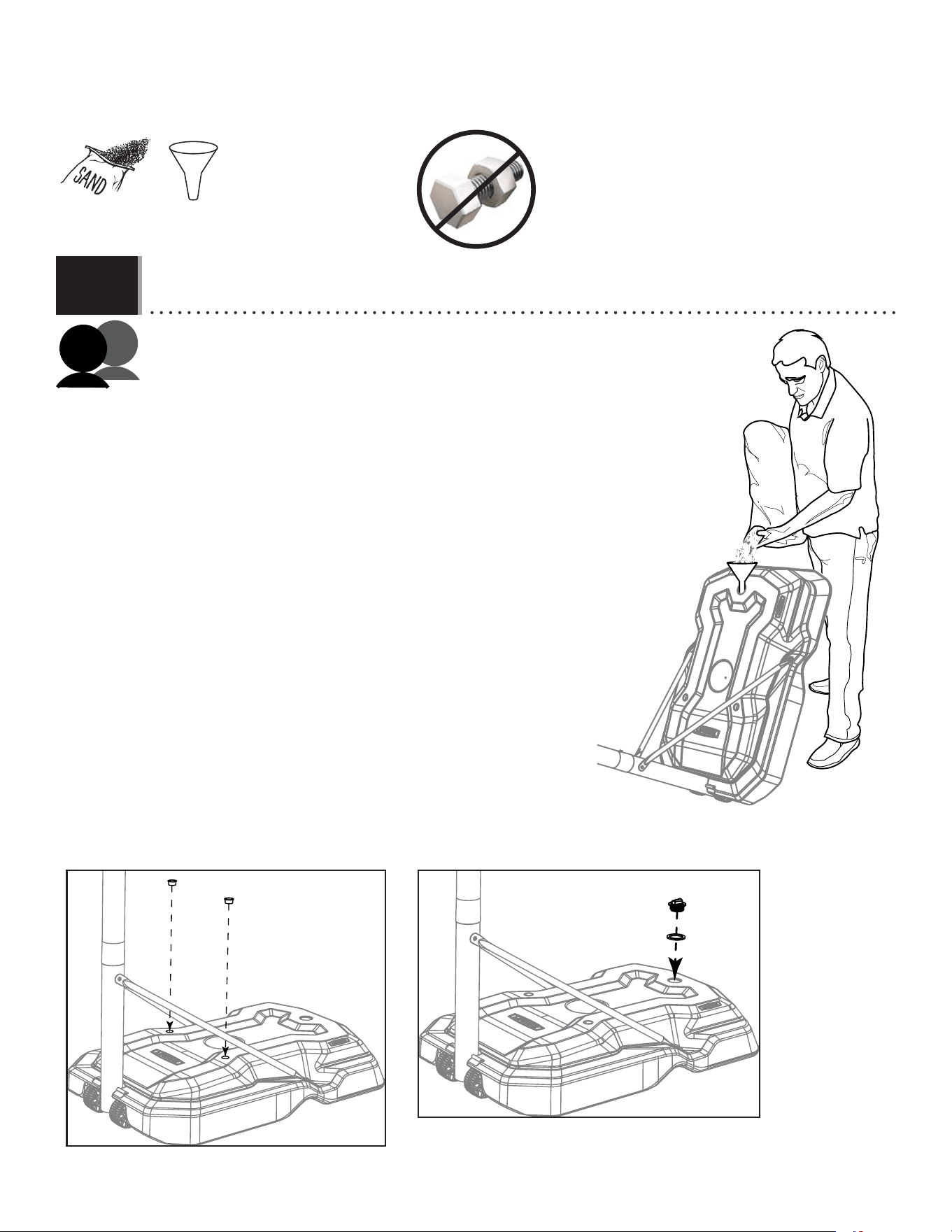
• To prevent serious injuries, the pole should be held down by one adult at all times while the other fi lls the base.
• Pour éviter des blessures graves, un adulte doit tenir le poteau en tout temps pendant le remplissage de la base.
• Para evitar lesiones graves, un adulto debe sostener el poste en todo momento mientras se llena la base.
Option a: fi lling the base with sand:
(325 lb (≈148 kg) of sand required)
1. Insert a plug (AEF) into each of the two holes in the base (Fig. 1).
2. Using a funnel, fi ll the base with sand (Fig. 2).
3. Using two adults, stand the base up on a smooth surface and
continue fi lling until you have, at least, 325 lb (≈147kg) of sand in
the base.
4. Place the gasket (FIR) onto the cap (FIQ) and screw the cap onto the
base until tight (Fig. 3).
Option a: remplir la base de sable:
(325 lb (≈148 kg) de sable requis)
1. Insérer un bouchon (AEF) dans chacun des deux trous dans la base
(Fig. 1).
2. En utilisant un entonnoir, remplir la base de sable (Fig. 2).
3. À l’aide de deux adultes, mettre la base sur un surface lisse et
continuer à remplir jusqu’à ce que la base ait, au moins, 325 lb
(≈147kg) de sable dans la base.
4. Mettre le joint (FIR) sur le capuchon (FIQ) et visser le capuchon sur
la base jusqu’à ce qu’il soit bien serré (Fig. 3).
Opción a: llenar la base con arena:
(325 lb (≈148 kg) de arena requerida)
1. Insertar un tapón (AEF) en cada uno de los dos orifi cios en la base
(Fig. 1).
2. Usando un embudo, llenar la base con arena (Fig. 2).
3. Con la ayuda de dos adultos, colocar la base sobre una
superfi cie lisa y continuar llenando hasta que la base haya, al
menos, 325 lb (≈147kg) de arena en la base.
4. Colocar la junta (FIR) sobre el tapón (FIQ) y atornillar bien el tapón
en la base (Fig. 3).
(x1)
AEF
AEF
FIQ
FIR
Fig. 1
Fig. 3
Fig. 2
Sand
Sable
Arena
37
TOOLS AND HARDWARE REQUIRED / OUTILS ET QUINCAILLERIE REQUIS / INSTRUMENTAL Y HERRAJE REQUERIDOS
SECTION 6 (CONTINUED) / SECTION 6 (SUITE) / SECCIÓN 6 (CONTINUACIÓN)
AJM
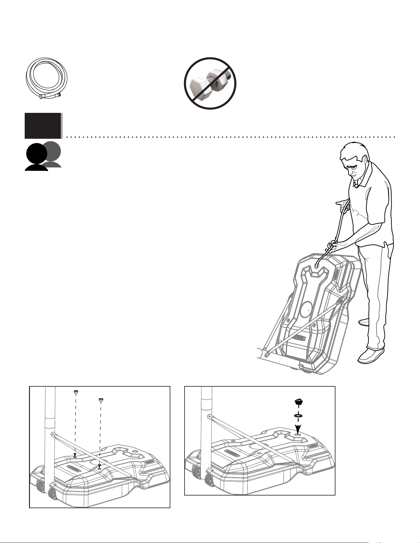
Option b: fi lling the base with water:
1. Insert a plug (AEF) into each of the two holes in the base (Fig. 1).
2. Using a hose, fi ll the base with cold water up to the fi ll hole, leaving two inches of space at
the top for expansion (Fig. 2).
3. Add one tablespoon of chlorine bleach to the water to prevent algae formation.
4. Using two adults, stand the base up on a smooth surface.
5. Place the gasket (FIR) onto the cap (FIQ) and screw the cap onto the base until tight (Fig.
3).
6. Check for leaks.
Option b: fi lling the base with water:
1. Insérer un bouchon (AEF) dans chacun des deux trous dans la base (Fig. 1).
2. En utilisant un tuyau, remplir la base d’eau froide jusqu’au trou de
remplissage, en laissant cinq centimètres d’espace en haut pour
l’expansion (Fig. 2).
3. Ajuter un cuillère à soupe d’eau de javel à l’eau pour éviter la formation
d’algues.
4. Mettre le joint (FIR) sur le capuchon (FIQ) et visser le capuchon sur la base
jusqu’à ce qu’il soit bien serré (Fig. 3).
5. À l’aide de deux adultes, mettre la base sur un surface lisse.
6. Vérifi er les fuites.
Option b: fi lling the base with water:
1. Insertar un tapón (AEF) en cada uno de los dos orifi cios en la base (Fig.
1).
2. Usando una manguera, llenar la base con agua fría hasta el orifi cio
de llenado, dejando cinco centímetros de espacio en la parte
superior para la expansión (Fig. 2).
3. Agregar una cucharada de blanqueador con cloro al agua para
evitar la formación de algas.
4. Con la ayuda de dos adultos, colocar la base sobre una superfi cie
lisa.
5. Colocar la junta (FIR) sobre el tapón (FIQ) y atornillar bien el tapón en la
base (Fig. 3).
6. Verifi car si hay fugas.
(x1)
6.4b
Fig. 2
• To prevent serious injuries, the pole should be held down by one adult at all times while the other fi lls the base.
• Pour éviter des blessures graves, un adulte doit tenir le poteau en tout temps pendant le remplissage de la base.
• Para evitar lesiones graves, un adulto debe sostener el poste en todo momento mientras se llena la base.
AEF
AEF
FIQ
FIR
Fig. 1
Fig. 3
38
TOOLS AND HARDWARE REQUIRED / OUTILS ET QUINCAILLERIE REQUIS / INSTRUMENTAL Y HERRAJE REQUERIDOS
SECTION 6 (CONTINUED) / SECTION 6 (SUITE) / SECCIÓN 6 (CONTINUACIÓN)
6.4
6.5
AKZ
ALX
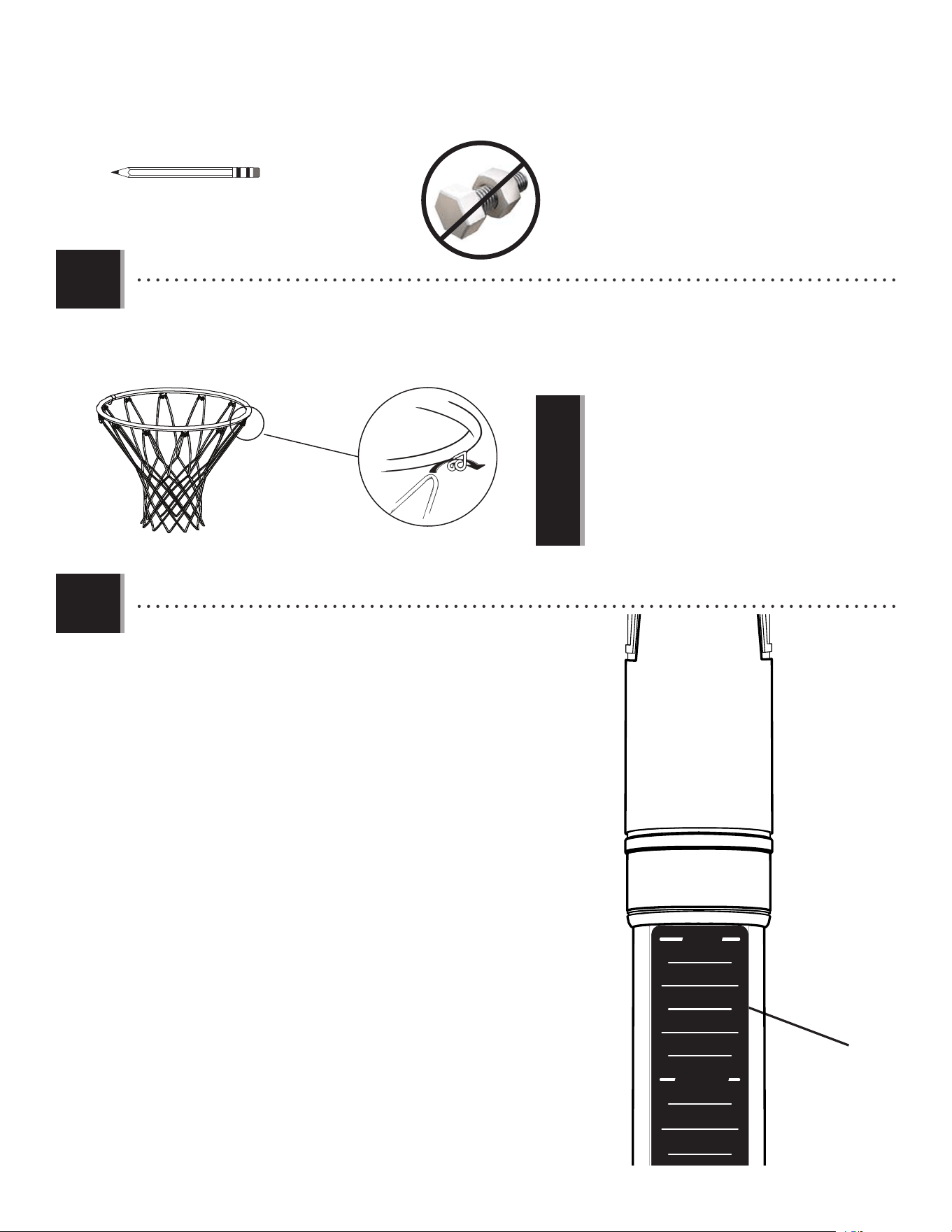
• Attach the net (AKZ) to the rim (ALX).
• Attachez la fi let (AKZ) à l’anneau (ALX).
• Sujete la red (AKZ) al aro (ALX).
• If a replacement net is needed, please call our customer
service department. Our nets are shorter than average to
reduce the risk of entanglement.
• Si vous avez besoin d’une nouvelle fi let, appelez notre
département de services à la clientèle. Nos fi lets sont plus
courtes pour réduire le risque d’enchevêtrement.
• Si se necesita una red de repuesto, llame a nuestro
departamento de servicios a clientes. Nuestras redes son
más cortas para reducir el riesgo de enredamiento.
!
(x1)
• Raise the backboard until the top of the rim measures 10 feet from
the playing surface. Apply the height adjustment sticker (AKP) onto the
gas spring (GFL), lining up the edge of the gas spring cover with the 10-
foot mark on the sticker. Press the sticker into place while carefully
removing the rest of the backing.
• Lever le panneau jusqu'à ce que la partie supérieure de l'anneau
mesure 10' (304.8 cm) de la surface de jeu. Appliquer l'autocollant de
hauteur d'ajustement (AKP) sur le ressort à gaz (GFL), en alignant le bord
du couvercle du ressort à gaz avec la marque de 10' (304.8 cm) sur
l'autocollant. Appliquer l'autocollant en place en enlevant avec soin
le reste du papier de protection.
• Levantar el tablero hasta que la parte superior del aro mida 10'
(304.8 cm) de la superifi ce de juego. Aplicar la etiqueta de altura
de ajuste (AKP) sobre el resorte de gas (GFL), alineando el borde de
la cubierta del resorte de gas con la marca de 10' (304.8 cm) en la
etiqueta. Presionar la etiqueta en su lugar mientras que remueve
cuidadosamente el resto del papel protector.
AKP
1202457
10'
9.5'
9'
8.5'
7.5'
8'
AKF
AKG

39
The life of your basketball system depends on many variables. The climate, exposure to corrosives such as salt, pesticides, or herbicides,
and excessive use or misuse can all contribute to pole failure, which may cause property damage or personal injury. Check your
basketball system frequently for loose hardware, excessive wear, and signs of corrosion. For safety reasons, and to prolong the
life of your basketball system, you must take the following preventive measures.
A. Check all nuts and bolts. If any are loose, tighten them.
B. Check all parts for excessive wear and tear. If necessary, replace any parts that have been worn or damaged through usage.
Contact our customer service department for replacement parts.
C. Inspect the warning sticker on the pole. If it is ripped, faded, or illegible, call our customer service department to request a
replacement sticker.
D. Check all pole sections for visible rust or chipped or cracked paint. If either are present, do the following:
1. Use an emery cloth to completely remove any rust or chipped paint.
2. Clean the area with a damp cloth and allow it to dry.
3. Apply two coats of a rust preventative, high gloss enamel paint to the area. Allow the paint to dry between coats.
IF RUST HAS PENETRATED ANYWHERE THROUGH THE POLE, REPLACE THE POLE IMMEDIATELY!
MAINTENANCE / ENTRETIEN / MANTENIMIENTO
La vie utile du système de basket-ball dépend de nombreuses conditions. Le climat, l’exposition aux produits corrosifs tels
que le sel, les pesticides ou herbicides, ainsi que l’usage excessif ou incorrect peuvent contribuer à la défaillance du poteau,
causant des dommages corporels et matériels.
Vérifier régulièrement le système de basket-ball au niveau d’accessoires manquants, d’usure excessive et de signes de
corrosion. Pour des raisons de sécurité et pour prolonger la vie du système de basket-ball, observer les mesures préventives
suivantes.
A. Vérifier l’état de tous les écrous et boulons. S’ils sont lâches, les serrer.
B. Vérifier toutes les pièces pour usure prématurée et excessive. Si nécessaire, changer toutes pièces usées ou
endommagées par l’utilisation. Contacter notre service clientèle pour des pièces de rechange.
C. Examiner l’autocollant d’avertissement situé sur le poteau. S’il est déchiré, décoloré ou illisible, appeler notre service
clientèle pour en demander un nouveau.
D. Vérifier toutes les sections de poteau au niveau de rouille ou de peinture craquelée ou égratignée. Si l’une de ces
conditions est présente, prendre les mesures suivantes :
1. Avec une toile d’émeri, enlever complètement la rouille ou la peinture endommagée.
2. Nettoyer la zone avec un linge humide et laisser sécher.
3. Appliquer deux couches d’une peinture antirouille émail-brillante sur l’endroit aff ecté. Laisser la peinture sécher entre
l’application des couches.
SI LA ROUILLE A PÉNÉTRÉ DANS LE POTEAU À UN ENDROIT QUELCONQUE, IL FAUT LE REMPLACER IMMÉDIATEMENT!
La vida útil de su sistema de baloncesto depende de muchas variables. El clima, los agentes corrosivos, y el uso excesivo
o indebido pueden contribuir a la falla del poste y producir averías a la propiedad o lesiones personales. Inspeccione
el sistema con frecuencia para ver si hay herrajes flojos, desgaste excesivo y corrosión. Usted debe tomar las medidas
preventivas siguientes.
A. Inspeccionar todas las tuercas y pernos, y apretar los que estén flojos.
B. Inspeccionar todas las partes para ver si muestran desgaste excesivo. Cambiar las piezas gastadas o dañadas.
C. Inspeccionar el auto-adhesivo de advertencia en el poste. Si está rasgado, desteñido, o ilegible, ponerse en contacto con
la tienda donde lo compró para obtener otro.
D. Inspeccionar las secciones del poste para ver si muestran óxido o pintura rajada o desportillada. Si encuentra algunas de
estas señales:
1. Quitar todo el óxido o pintura desportillada con tela de esmeril.
2. Limpiar el área con un trapo húmedo y dejarla secar.
3. Aplicar dos capas de pintura de esmalte resistente al óxido. Dejar secar la pintura entre una y otra capa.
¡SI EL ÓXIDO HA ATRAVESADO EL POSTE EN ALGUNA PARTE, CAMBIAR EL POSTE INMEDIATAMENTE!
40
!
!
MOVING THE SYSTEM / DÉPLACER LE SYSTÈME / DEPLAZANDO EL SISTEMA
WARNING:
The system must only be moved by people capable of handling its weight. Children should not be allowed
to move the system.
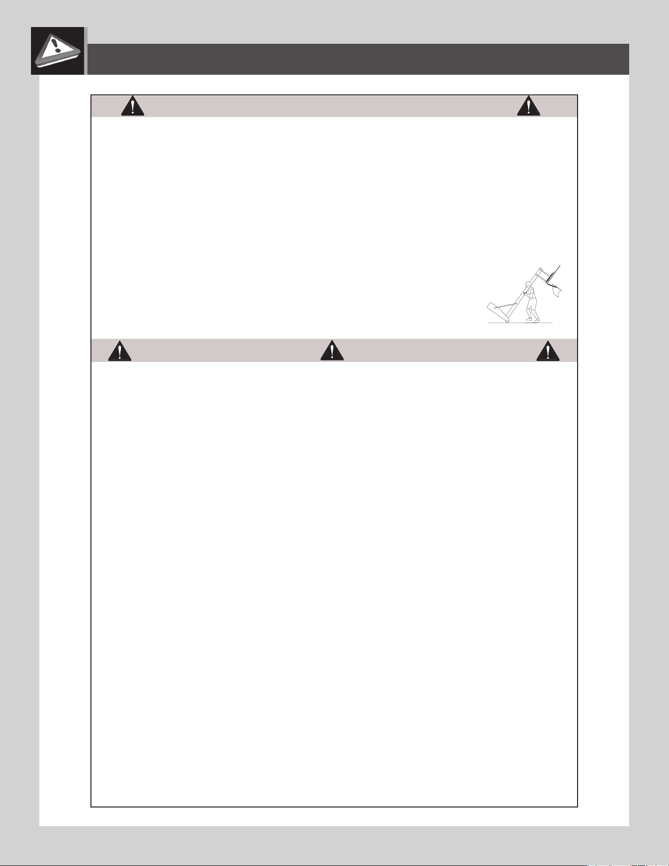
1. Adjust the system to its lowest position, and use caution to prevent the height mechanism from adjusting.
2. Stand in front of the system and pull on the Pole until the unit is balanced on its Wheels.
3. Move the system to the desired location and carefully set the Base down.
CAUTION:
The system must only be moved on its Wheels. Sliding the Base may damage the Base which could result
in leakage and the system tipping over.
AVERTISSEMENT :
Ce système ne doit être déplacé que par des personnes capables de soutenir son poids. Il ne
faut pas permettre aux enfants de déplacer le système.
1. Régler l’élément à son niveau plus bas.
2. Se tenir derrière le système et tirer sur le poteau jusqu’à ce que l’unité soit en équilibre sur ses roues.
3. Déplacer le système dans le lieu désiré et poser prudemment la base.
ATTENTION :
Le système ne doit être déplacé que sur ses roues. Le glissement de la base peut l’endommager,
produire une fuite et le renversement du système.
ADVERTENCIA:
Transportar el sistema sólo con personas capaces de soportar su peso. No permitir a los niños
transportar el sistema.
1. Ajustar el sistema a su posición más bajo.
2. Mirando la parte posterior del sistema portátil, tirar de la unidad del poste hasta que quede equilibrada sobre sus ruedas.
3. Mover el sistema cuidadosamente y bajar la base.
PRECAUCIÓN:
Transportar el sistema sobre sus ruedas solamente. Deslizando la base puede dañar la base la cual
puede ocasionar en un escape y la caída del sistema.
!
!
!
!

41
NOTES / REMARQUES / NOTAS

42
NOTES / REMARQUES / NOTAS
43
WARNING STICKER / AUTOCOLLANT D’AVERTISSEMENT / ETIQUETA DE ADVERTENCIA
FAUTE DE NE PAS SUIVRE CES AVERTISSEMENTS, VOUS RISQUEZ DE CAUSER
DES BLESSURES GRAVES ET/OU DES DOMMAGES À L’ÉQUIPEMENT.
Le propriétaire doit s’assurer que tous les joueurs
connaissent et appliquent les règles suivantes afin d’utiliser
l’équipement en toute sécurité.
SI NO SE OBEDECEN ESTAS ADVERTENCIAS PUEDEN PRODUCIRSE
GRAVES LESIONES Y/O DAÑOS A LA PROPIEDAD.
El propietario del sistema debe asegurarse de que todos
los jugadores conozcan y respeten estas reglas para que el
sistema se use en forma segura.
FAILURE TO FOLLOW THESE WARNINGS MAY RESULT IN SERIOUS INJURY
AND/OR PROPERTY DAMAGE.
Owners must ensure that all players know and follow these
rules for safe operation of the system.
• Only hang from the rim briefly to regain balance or avoid injuring
others. Release the rim as soon as safely possible.
• During play, especially when performing dunk type activities, keep
player’s face away from the backboard, rim, and net. Serious injury
could occur if teeth/face come in contact with the backboard, rim, or
Net. Player should wear a mouth guard during play.
• Do not slide, climb, or play on base or pole.
• Completely fill base according to manufacturer’s instructions. Never
leave the unit standing in an upright position without first filling the base
with weight or the system will tip quickly causing serious personal injury.
• When adjusting height or moving system, keep hands and fingers
away from moving parts.
• Do not allow children to move or adjust system.
• Do not wear jewelry (rings, watches, necklaces, etc.) during play.
Objects may entangle in net.
• Keep water and organic material away from pole base. Grass, litter,
etc. could cause corrosion and/or deterioration.
• Never play on damaged equipment.
• Surface beneath the base must be smooth and free of gravel or other
objects. Punctures cause leakage and could cause system to tip over.
• Once a month check pole and all metal parts for signs of
corrosion (rust, pitting, chipping). Completely remove rust and
repaint with exterior enamel. If rust has penetrated any steel part,
replace that part immediately.
• Check system before each use for proper ballast, loose hardware,
excessive wear, instability, and signs of corrosion and repair before use.
• Do not use system during windy or severe weather. System may
tip over. Place system in an area protected from the wind or in an
area away from property that may be damaged if the system falls,
and from overhead power lines.
• Do not use the system to lift or hoist anything. The mechanism is
designed to lift only the weight of the backboard and rim. Do not
hang anything from the handle, rim, backboard, or lifter arms as
this will damage the system and void the warranty.
• Ne pas se suspendre à l’anneau plus que nécessaire pour
retrouver l'équilibre ou éviter de blesser les autres joueurs.
Relâcher l’anneau aussitôt que possible.
• Lors d’un match, particulièrement dans le cas des smashs, le
visage du joueur ne doit pas faire face au panneau, à l’anneau, ni au
filet. Le joueur risque de graves blessures si ses dents ou son visage
entrent en contact avec le panneau, l’anneau, ou le filet. Les joueurs
doivent toujours porter un protège-dents lorsqu’ils jouent.
• Ne pas glisser, ne pas grimper, et ne pas jouer sur la base ou le
poteau.
• Remplir complètement la base selon les instructions du fabricant.
Ne jamais laisser l’unité debout de plein pied sans avoir d’abord rempli
la base avec un poids ou l’équipement pourrait basculer rapidement
et causer de graves blessures.
• Lors du réglage de la hauteur ou lors du déplacement
de l’équipement, garder les mains et doigts loin des pièces mobiles.
• Ne pas permettre aux enfants de déplacer ou d’ajuster l’équipement.
• Ne pas porter de bijoux (bagues, montres, colliers, etc.) pendant le
jeu. Ces objets pourraient s’accrocher au filet.
• La surface sur laquelle est posée la base doit être lisse et sans
gravier ou tout autre objet qui pourrait trouer la base entraînant ainsi
une fuite ce qui pourrait faire basculer l’équipement.
• Garder de l’eau et de la matiére organique loin de la base. Le
gazon, les déchets, etc. pourraient provoquer la corrosion et/ou la
détérioration.
• Une fois par mois, vérifier que le poteau et toutes les pièces en métal
ne montrent pas de signes de corrosion (rouille, piqûres, écaillage).
Enlever toute la rouille et repeindre complètement avec une peinture
pour extérieur. Si la rouille a pénétré une des pièces en acier, il
faut la remplacer immédiatement la pièce en question.
• Chaque fois avant d'utiliser le système, vérifier d’abord l’équilibre,
la possibilité de pièces desserrées ou usées, la stabilité de
l’équipement et tout signe de corrosion ou réparation nécessaire avant
utilisation.
• Ne jamais jouer avec un équipement endommagé.
• Ne pas utiliser l’équipement lors de fortes rafales de vent ou
de mauvais temps. L’équipement pourrait basculer. Placer
l’équipement dans un endroit abrité du vent ou loin des structures
qu’il pourrait endommager s’il basculait, et loin des fils électriques.
• Ne pas utiliser l’équipement pour lever ou soulever quoique ce
soit. Son mécanisme a été conçu uniquement pour soutenir le
poids du panneau et de l’anneau. Ne rien accrocher au manche,
à l’anneau, au panneau ni aux leviers sous peine d’endommager
l’équipement et d’annuler la garantie.
•Colgarse del aro sólo en forma breve, para recuperar el equilibrio
o evitar lesionar a otros jugadores. Soltarse del aro lo más pronto que
pueda hacerlo con seguridad.
• Durante el juego, especialmente al embocar violentamente de alto,
la cara de los jugadores debe mantenerse alejada del tablero, el aro
y la red. Pueden producirse lesiones graves si los dientes o la cara
entran en contacto con el tablero, el aro o la red. Los jugadores deben
usar un protector bucal durante el juego.
• No deslizarse, no trepar ni jugar sobre la base o el poste.
• Llenar la base completamente siguiendo las instrucciones del
fabricante. Nunca dejar la unidad en posición de uso sin haber
llenado previamente la base con material de contrapeso, pues el
sistema podría tumbarse rápidamente y causar graves lesiones
personales.
• Mantener las manos y los dedos alejados de las piezas movibles
al regular la altura o al desplazar el sistema.
• No dejar que los niños regulen ni desplacen el sistema.
• No usar joyas (anillos, relojes, collares o gargantillas, etc.) durante
el juego. Estos objetos pueden engancharse en la red.
• La superficie donde se coloque la base debe estar lisa y desprovista
de piedras, grava u otros objetos. Las perforaciones pueden originar
pérdidas, y éstas pueden hacer que el sistema se tumbe.
• Guardar aqua y materia orgánica. Césped, basura, etc.,
prodrian causar corrosión et/o deterioros.
• Controlar el poste y todas las piezas metálicas una vez al mes
en busca de signos visibles de corrosión (oxidación, picaduras,
escamado). Eliminar todo rastro de óxido y volver a pintar con esmalte
para exteriores. Si el óxido ha penetrado cualquier pieza de acero,
reemplazar esa pieza de inmediato.
• Inspeccionar el sistema antes de cada uso para verificar que esté
adecuadamente contrapesado, que los elementos de fijación no
estén flojos, que no haya desgaste excesivo, inestabilidad ni signos
de corrosión. Al encontrar irregularidades, repararlas antes de usar
el sistema. Nunca jugar con un equipo dañado.
• No usar el sistema en presencia de vientos fuertes o condiciones
climáticas adversas, ya que puede tumbarse. Colocar la unidad en
una posición de almacenamiento y/o en una zona a resguardo
del viento, lejos de propiedades personales que puedan dañarse
si el sistema se cae, y de líneas de suministro de energía.
• No usar el sistema para levantar ningún objeto. El mecanismo está
diseñado para elevar solamente el peso del tablero con el aro. No
colgar nada de la agarradera, el aro, el tablero ni los brazos de
elevación, ya que esto puede dañar el sistema y anular la garantía.
www.lifetime.com
# 1180194
11/23/2015
Lifetime Products, Inc., Clearfield, UT 84016
1-800-225-3865
WARNING
ADVERTENCIAAVERTISSEMENT

44
LIFETIME’S PROMISE TO YOU:
We invite you to read our privacy policy at www.lifetime.com
REGISTER today!
At Lifetime
®
, we are committed to providing innovative and quality products. While registering, you will have the opportunity to give us your feedback. Your input is
valuable to us.
• You can also opt in to receive new product notifi cations or promotions.
• In the unlikely event of a product recall or safety modifi cation, your registration provides the information we need to notify you directly.
• Registration is fast, easy, and completely voluntary.
Maintaining your privacy is our long-standing policy at Lifetime
®
. And you can rest assured that Lifetime
®
will not sell or provide your personal data to other third parties,
or allow them to use your personal data for their own purposes.
LA PROMESA DE LIFETIME
®
PARA USTED:
Lo invitamos a leer nuestra política de privacidad en www.lifetime.com (sólo en inglés)
¡REGISTRARSE hoy mismo!
En Lifetime
®
, estamos comprometidos a ofrecer productos innovadores y de calidad. Al registrarse, usted tendrá la oportunidad de darnos su retroalimentación. Su
información es valiosa para nosotros.
• También puede optar por recibir nuestras notifi caciones o promociones.
• En el caso improbable de que el producto deba ser retirado del mercado o que sufra alguna modifi cación, su registro provee la
información que necesitamos para notifi carle directamente.
• El registro es rápido, fácil y completamente voluntario.
Mantener privacidad es nuestra política permanente en Lifetime
®
. Y puede estar seguro que Lifetime
®
no venderá ni dará datos personales a terceros, ni les permitirá usar
datos personales para sus propios fi nes.
LA PROMESSE DE LIFETIME :
Nous vous invitons à lire notre politique de confi dentialité à www.lifetime.com (en anglais seulement)
ENREGISTRER CE PRODUIT aujourd’hui!
Chez Lifetime
®
, nous nous engageons à fournir des produits innovateurs de qualité. Lors de votre inscription, vous aurez l’occasion de nous faire parvenir vos com-
mentaires. Votre opinion est importante pour nous.
• On peut également choisir de recevoir des avis ou des promotions dans le cadre de nouveaux produits.
• Dans l’éventualité peu probable d’un rappel ou d’un avis de sécurité, l’inscription fournit les renseignements nécessaires nous
permettant de communiquer avec vous.
• L’inscription est rapide, facile et complètement volontaire.
Conserver votre confi dentialité est notre politique de longue date chez Lifetime
®
. Vous pouvez donc être rassuré par le fait que Lifetime
®
ne vendra pas ou ne fournira
pas vos données personnelles à des tiers, et ne leur permettra pas d’utiliser vos données personnelles à leurs propres fi ns.
REGISTER YOUR PRODUCT ONLINE AT WWW.LIFETIME.COM
REGISTRAR EL PRODUCTO EN LÍNEA EN WWW.LIFETIME.COM
ENREGISTRER CE PRODUIT EN LIGNE À WWW.LIFETIME.COM

45
THE MANUFACTURER RESERVES THE RIGHT TO MAKE SUBSTITUTIONS TO WARRANTY CLAIMS IF PARTS ARE UNAVAILABLE OR OBSOLETE.
1. Lifetime basketball systems are warranted to the original purchaser to be free from defects in material or workmanship for a
period of fi ve years (60 months) from the date of original retail purchase. The word “defects” is defi ned as imperfections that
impair the use of the product. Defects resulting from misuse, abuse or negligence will void this warranty. This warranty does not
cover defects due to improper installation, alteration or accident. This warranty does not cover damage caused by vandalism,
rusting, “acts of nature” or any other event beyond the control of the manufacturer.
2. This warranty is nontransferable and is expressly limited to the repair or replacement of defective product. If the product is
defective within the terms of this warranty, Lifetime Products, Inc. will repair or replace defective parts at no cost to the purchaser.
Shipping charges to and from the factory or distribution center are not covered and are the responsibility of the purchaser. Labor
charges and related expenses for removal, installation or replacement of the product or its components are not covered under
this warranty.
3. This warranty does not cover scratching or scuffi ng of the product that may result from normal usage. In addition, defects
resulting from intentional damage, negligence, unreasonable use or hanging from the rim will void this warranty.
4. Liability for incidental or consequential damages is excluded to the extent permitted by law. While every attempt is made to
embody the highest degree of safety in all equipment, freedom from injury cannot be guaranteed. The user assumes all risk of
injury resulting from the use of this product. All merchandise is sold on this condition, and no representative of the company
may waive or change this policy.
5. This product is not intended for institutional or commercial use; Lifetime Products, Inc. does not assume any liability for such use.
Institutional or commercial use will void the warranty.
6. Our goods come with guarantees that cannot be excluded under the Australian Consumer Law. You are entitled to a replacement
or refund for a major failure and for compensation for any other reasonably foreseeable loss or damage. You are also entitled to
have the goods repaired or replaced if the goods fail to be of acceptable quality and the failure does not amount to a major failure.
7. This warranty is expressly in lieu of all other warranties, expressed or implied, including warranties of merchantability or fi tness
for use to extent permitted by Federal and state law. Neither Lifetime Products, Inc., nor any representative assumes any other
liability in connection with this product. This warranty gives you specifi c legal rights, and you may also have other rights which
vary from state to state.
www.lifetime.com
PLEASE INCLUDE YOUR DATED SALES RECEIPT AND PHOTOGRAPHS OF DAMAGED PARTS.
REPORT PRODUCT DEFECTS IN WRITING TO:
Lifetime Products, Inc., PO Box 160010 Clearfi eld, UT 84016-0010 or dial 1-800-225-3865.
REGISTER YOUR PRODUCT FOR QUICKER CUSTOMER SERVICE.
Visit www.lifetime.com or dial 1-800-225-3865 to register your product today.
FOR INTERNATIONAL WARRANTY CLAIMS:
All warranty claims must be accompanied by a sales receipt. Report all warranty claims in writing to your regional sales
support representative. Please include your dated sales receipt and photographs of damaged parts.
To Identify the representative for your region, please visit: www.lifetime.com/international
5-YEAR LIMITED FACTORY WARRANTY
W
A
R
R
A
N
T
Y
W
A
R
R
A
N
T
Y
WARRANTY

46
LE FABRICANT RÉSERVE LE DROIT DE FAIRE DES SUBSTITUTIONS EN CAS DE RECOURS EN GARANTIE SI LES PIÈCES NE SONT PAS
DISPONIBLES OU SONT OBSOLÈTES
1. Les systèmes de basket-ball Lifetime sont garantis à l’acheteur d’origine contre tous défauts de matériau ou de fabrication
pendant une durée de cinq ans à partir de la date d’achat d’origine. Le mot « défauts » signifi e des défectuosités qui empêchent
l’utilisation du produit. Les défauts résultant de mauvais usage, d’abus ou de négligence annulent cette garantie. Cette garantie
ne couvre pas les dommages causés par le vandalisme, la rouille, « les actes de la nature » ou tout autre événement en dehors
du contrôle du fabricant.
2. Cette garantie n’est pas transférable et est expressément limitée à la réparation ou au remplacement du produit défectueux.
Si le produit est déclaré défectueux selon les termes de cette garantie, Lifetime Products, Inc. réparera ou remplacera les parties
défectueuses gratuitement pour l’acheteur. Les frais d’expéditions aller et retour de l’usine ne sont pas couverts et sont à la charge
de l’acheteur. Les frais de main-d’oeuvre et frais associés à l’enlèvement, au montage ou au remplacement du système de basket-
ball ou de ses composantes ne sont pas couverts par cette garantie.
3. Cette garantie ne couvre pas les égratignures ou éraillements du produits résultant d’une utilisation normale. Par ailleurs,
les défectuosités résultant de dommages intentionnels, négligence, utilisation abusive ou suspension à partir de l’entretoise
annulent cette garantie
4. Toute responsabilité pour dommages incidents ou conséquents est exclue dans la mesure permise par la loi. Bien que toutes
les mesures aient été prises pour intégrer le plus haut degré de sécurité dans l’ensemble du matériel, l’impossibilité de blessure
ne peut pas être garantie. L’utilisateur assume tous les risques de blessure résultant de l’utilisation de ce produit. L’ensemble
de la marchandise est vendu en vertu de cette condition et aucune personne représentant la société ne peut déroger à cette
politique, ni la modifi er.
5. Ce produit n’est pas prévu pour l’usage institutionnel ni commercial; Lifetime Products, Inc. n’assume aucune responsabilité pour
tel usage. L’utilisation institutionnelle ou commerciale annulera cette garantie.
6. Cette garantie remplace expressément toutes autres garanties, expresses ou tacites, y compris les garanties de commercialisation
ou d’adaptation à un but particulier dans la mesure permise par les lois fédéraux et les états. Ni Lifetime Products, Inc. ni
aucun de ses représentants n’assure aucune autre responsabilité concernant ce produit. Cette garantie vous accorde des droits
particuliers, et vous aurez peut-être d’autres droits qui varient d’un état à l’autre.
TOUS LES RECOURS EN GARANTIE DOIVENT ÊTRE ACCOMPAGNÉS DU REÇU DE VENTE.
FAIRE PARVENIR UN RAPPORT PAR ÉCRIT DE DÉFECTUOSITÉ DU PRODUIT À :
Lifetime Products, Inc., PO Box 160010 Clearfi eld, UT 84016-0010 ou composer le 1-800-225-3865.
ENREGISTREZ VOTRE ARTICLE À :
www.lifetime.com, ou composer le 1-800-225-3865 pour enregistrer votre article aujourd’hui.
POUR RECOURS EN GARANTIE INTERNATIONAUX :
Tous les recours en garantie doivent être accompagnés du reçu de vente. Faire parvenir un rapport par écrit de défectuosité
du produit à votre représentant régional de ventes. Inclure votre reçu de vente daté et photographies des pièces
endommagées. Pour identifi er votre représentant régional, visitez www.lifetime.com/international
GARANTIE DE FABRICATION LIMITÉE DE 5 ANS
G
A
R
A
N
T
I
E
G
A
R
A
N
T
I
E
GARANTIE
www.lifetime.com

47
EL FABRICANTE SE RESERVA EL DERECHO DE HACER SUSTITUCIONES EN LOS ELEMENTOS REEMPLAZADOS BAJO GARANTÍA SI LAS PIEZAS NO ESTÁN DISPONIBLES O
SON OBSOLETAS.
1. El comprador original recibe la garantía de que los sistemas de basquetbol Lifetime estarán libres de defectos de material o de
mano de obra por un período de cinco años a contar desde la fecha de la compra original. La palabra “defectos” se defi ne como
imperfecciones que perjudican el uso del producto. Los defectos emergentes de un mal uso, abuso o negligencia invalidarán
esta garantía. Esta garantía no cubre defectos debidos a una instalación incorrecta, alteración o a un accidente. Esta garantía
no cubre daños causados por vandalismo, oxidación, “actos de la naturaleza” u otros eventos que estén más allá del control
del fabricante.
2. Esta garantía es intransferible, y queda expresamente limitada a la reparación o reemplazo de los productos defectuosos. Si
el producto se encuentra defectuoso dentro de los términos de esta garantía, Lifetime Products, Inc. reparará o reemplazará las
piezas defectuosas sin costo alguno para el comprador. Los gastos de envío hacia y desde la fábrica no están cubiertos, y quedan
bajo la responsabilidad del comprador. Los gastos de mano de obra y otros costos relacionados con la remoción, instalación o
reemplazo de este sistema o sus componentes no están cubiertos por esta garantía.
3. Esta garantía no cubre raspaduras ni marcas en el producto que pueden resultar de su uso normal. Además, los defectos
causados por daños intencionales, negligencia, uso irrazonable o por colgarse de la red o del aro invalidarán esta garantía.
4. La responsabilidad por daños incidentales o consecuentes queda excluida hasta el punto en que lo permita la ley. Si bien se
hace el mayor esfuerzo posible para lograr el más alto grado de seguridad en todos nuestros equipos, no puede garantizarse la
libertad de cualquier tipo de lesión. El usuario asume todos los riesgos de lesiones emergentes del uso de este producto. Toda
nuestra mercadería se vende bajo esta condición, y ningún representante de la compañía puede anular ni cambiar esta política.
5. Este producto no está pensado para el uso institucional ni comercial; Lifetime Products, Inc. no asume ninguna otra
responsabilidad en conexión con este producto. El uso institucional o comercial invalidará la garantía.
6. Esta garantía se otorga en reemplazo expreso de toda otra garantía, expresa o implícita, incluidas las garantías de
comercialización o adaptación para el uso en la medida permitida por las leyes federales y estatales. Ni Lifetime Products, Inc.,
ni ninguno de sus representantes asume ninguna otra responsabilidad en conexión con este producto. Esta garantía le otorga
derechos legales específi cos, y usted puede tener otros derechos que varían de estado a estado.
TODOS LOS RECLAMOS DE GARANTÍA DEBEN ESTAR ACOMPAÑADOS POR UN RECIBO DE COMPRA
INFORME POR ESCRITO LOS DEFECTOS EN EL PRODUCTO A:
Por favor, incluir el recibo de compra fechado y fotografías de las piezas dañadas.
Lifetime Products, Inc., PO Box 160010 Clearfi eld, UT 84016-0010, o marcar al 1.800.225.3865.
REGISTRE SU PRODUCTO
Visitar nuestra página en Internet www.lifetime.com, o marcar al 1.800.225.3865 para registrar el producto hoy.
PARA RECLAMOS DE GARANTÍA INTERNACIONALES:
Todos los reclamos de garantía deben estar acompañados por un recibo de compra. Informe por escrito todos los
reclamos de garantía a su representante regional de ventas. Favor de incluir su recibo de compra fechado y fotografías de
las piezas dañadas.
Para identifi car el representante de su región, visitar www.lifetime.com/international
NINGUNA GARANTÍA OFRECIDA POR EL FABRICANTE ES VÁLIDA EN MÉXICO
GARANTÍA DE FÁBRICA LIMITADA POR 5 AÑOS
G
A
R
A
N
T
Í
A
G
A
R
A
N
T
Í
A
GARANTÍA
www.lifetime.com
48
www.lifetime.com
Or dial 1-800-424-3865
To purchase accessories or other Lifetime
®
products, visit us at:
www.lifetime.com
O marcar al 1-800-424-3865
Para comprar accesorios u otros productos de Lifetime
®
, visitarnos en:
www.lifetime.com
ENHANCE YOUR LIFETIME
®
PURCHASE BY ADDING ACCESSORIES OR OTHER GREAT PRODUCTS
MEJORAR LA COMPRA DE LIFETIME
®
AGREGANDO ACCESORIOS U OTROS MARAVILLOSOS PRODUCTOS
Ou composer le 1-800-424-3865
Pour acheter des accessoires ou des autres produits Lifetime
®
, visiter le :
www.lifetime.com
AMÉLIORER L’ACHAT LIFETIME
®
EN AJOUTANT DES ACCESSOIRES OU D’AUTRES PRODUITS
1233854
12/05/2023