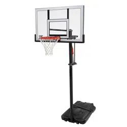
POWER LIFT
®
BASKETBALL SYSTEM
(x1)
(x1)
(x1)
(x1)
3/16"
(x2, included)
(375 lb)
(x1)
1/2", 3/4"
11/16"
(x2)
1/2", 9/16", 3/4"
(x1)
(x1)
(x1)
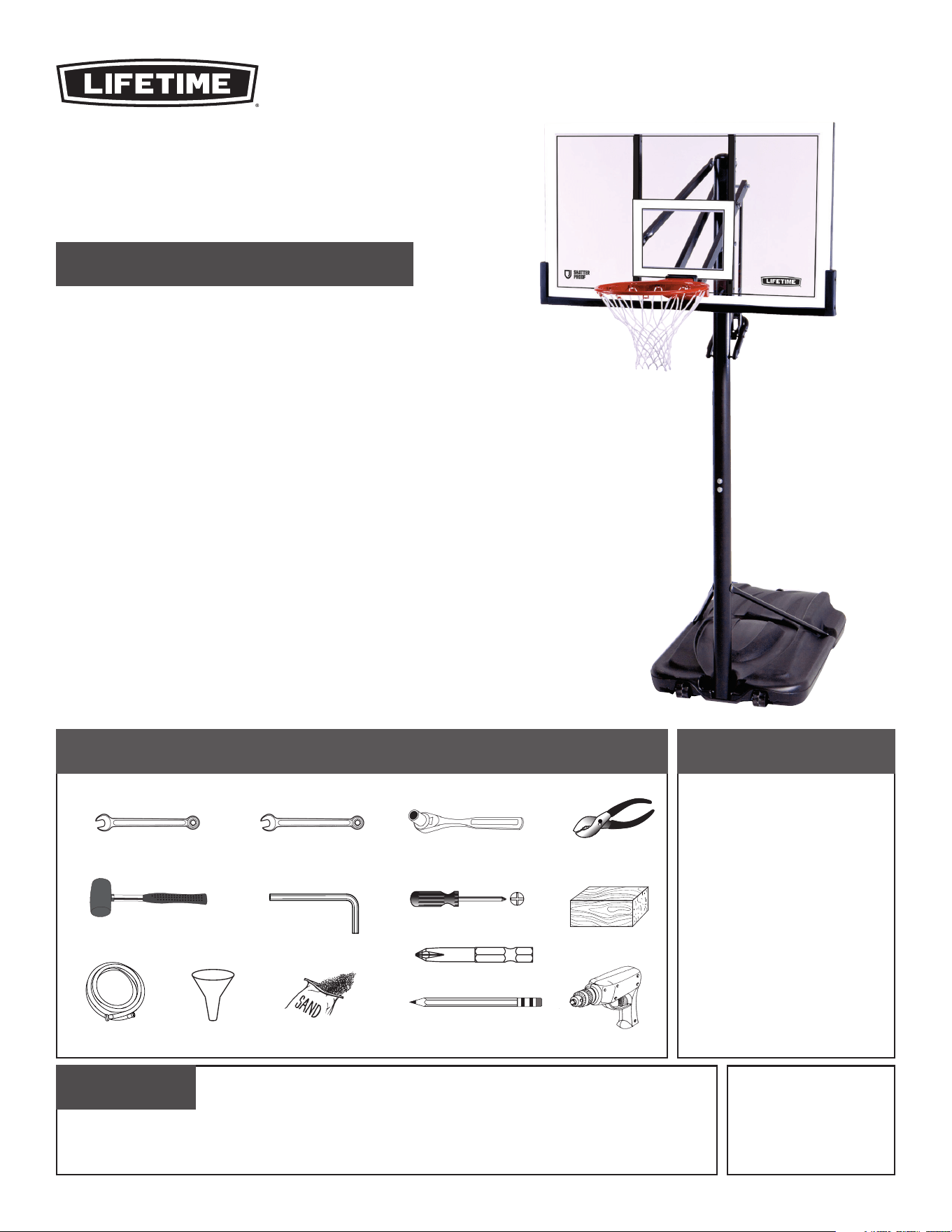
TOOLS REQUIRED TABLE OF CONTENTS
BEFORE ASSEMBLY:
• Decide with what to fi ll the base
(sand is recommended)
• At least 2 adults recommended for setup
ASSEMBLY INSTRUCTIONS
MODEL 90600
CONTACT LIFETIME
®
CUSTOMER SERVICE:
QUESTIONS?
Model Number: 90600
Product ID:
For Customer Service in Mainland Europe
and the United Kingdom,
E-mail: [email protected]
Live Chat:
www.lifetime.com/customerservice/home
(click on “Live Chat” tab)
(x1)
(x1)
Save this instruction in the event that the manufacturer must be contacted for replacement parts.
IMPORTANT, RETAIN FOR FUTURE REFERENCE: READ CAREFULLY
(x1)
Dial 1-800-225-3865
(English, Français, Español)
Icon legend..................................................................2
Warnings & notices......................................................3
Pole assembly..............................................................4
Pole-to-base assembly.................................................8
Backboard-to-rim assembly......................................13
Backboard-to-pole assembly.....................................18
Parts identifi er.........................................................i–iv
Handle assembly.......................................................25
Final assembly...........................................................30
Maintenance.......................................................35
Registration..........................................................35
Warning Sticker..........................................................38
Warranty............................................................39
2
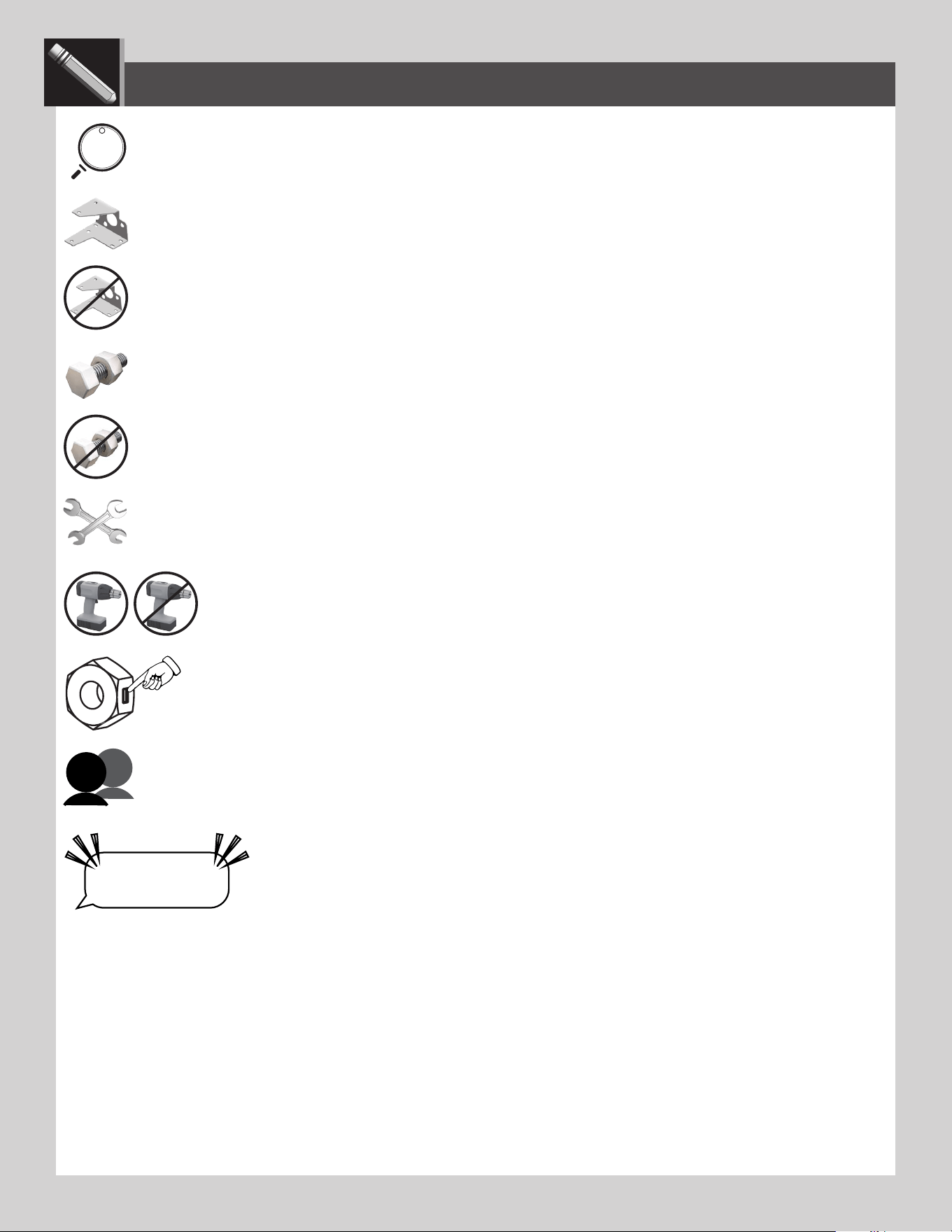
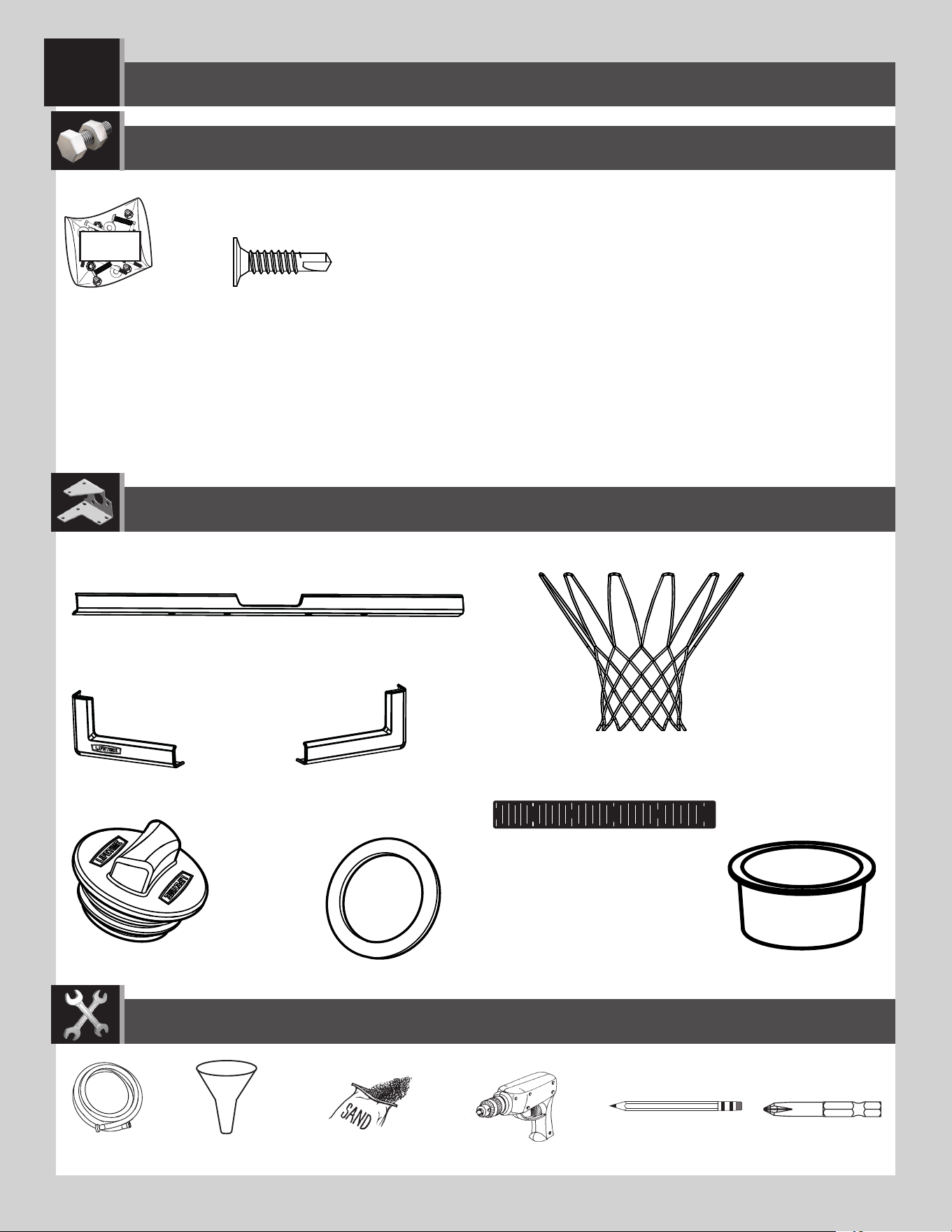
• Indicates the parts to be used for a section.
• Indicates special heed should be taken when reading.
• Indicates the hardware to be used for a section.
• Indicates the tools to be used for a section.
• Indicates no hardware required for a specifi c page.
• Indicates no parts required for a specifi c section.
• Indicates to use/not to use an electric drill for a specifi c step.
ICON LEGEND
• Indicates the use of a centerlock nut. A nut with this marking will require some e ort to tighten.
This hardware is designed with this feature in order to prevent loosening later.
• Indicates the number of adults required to perform a specifi c step, e.g., 2, 3, 4, etc.
• Indicates a specifc step is harder to perform.
“$#@*%!”
THIS STEP CAN BE DIFFICULT
LIFETIME
©
3
WARNINGS & NOTICES
Most injuries are caused by misuse and/or not following instructions. Use caution when using this product.
To ensure safety, do not attempt to assemble this product without following the instructions carefully. Check entire box and inside all packing
material for parts and/or additional instruction material. Before beginning assembly, read the instructions and identify parts using the hardware
identifi er and parts list in this document. Proper and complete assembly, use and supervision are essential for proper operation and to reduce the
risk of accident or injury. A high probability of serious injury exists if this product is not installed, maintained, and operated properly.
FAILURE TO FOLLOW THESE WARNINGS MAY RESULT IN SERIOUS INJURY OR PROPERTY DAMAGE AND WILL VOID WARRANTY.
Owner must ensure that all players know and follow these rules for safe operation of the system.
• If using a ladder during assembly, use extreme caution.
• Two capable adults are recommended for this operation.
• Check base daily for leakage. Leaks will cause system to fall.
• Assemble the pole sections properly. Failure to do so could cause the pole sections to separate during play or transport.
• Minimum operational height is 6 ft 6 in (1.98m) to the bottom of the backboard.
SAFETY INSTRUCTIONS
4
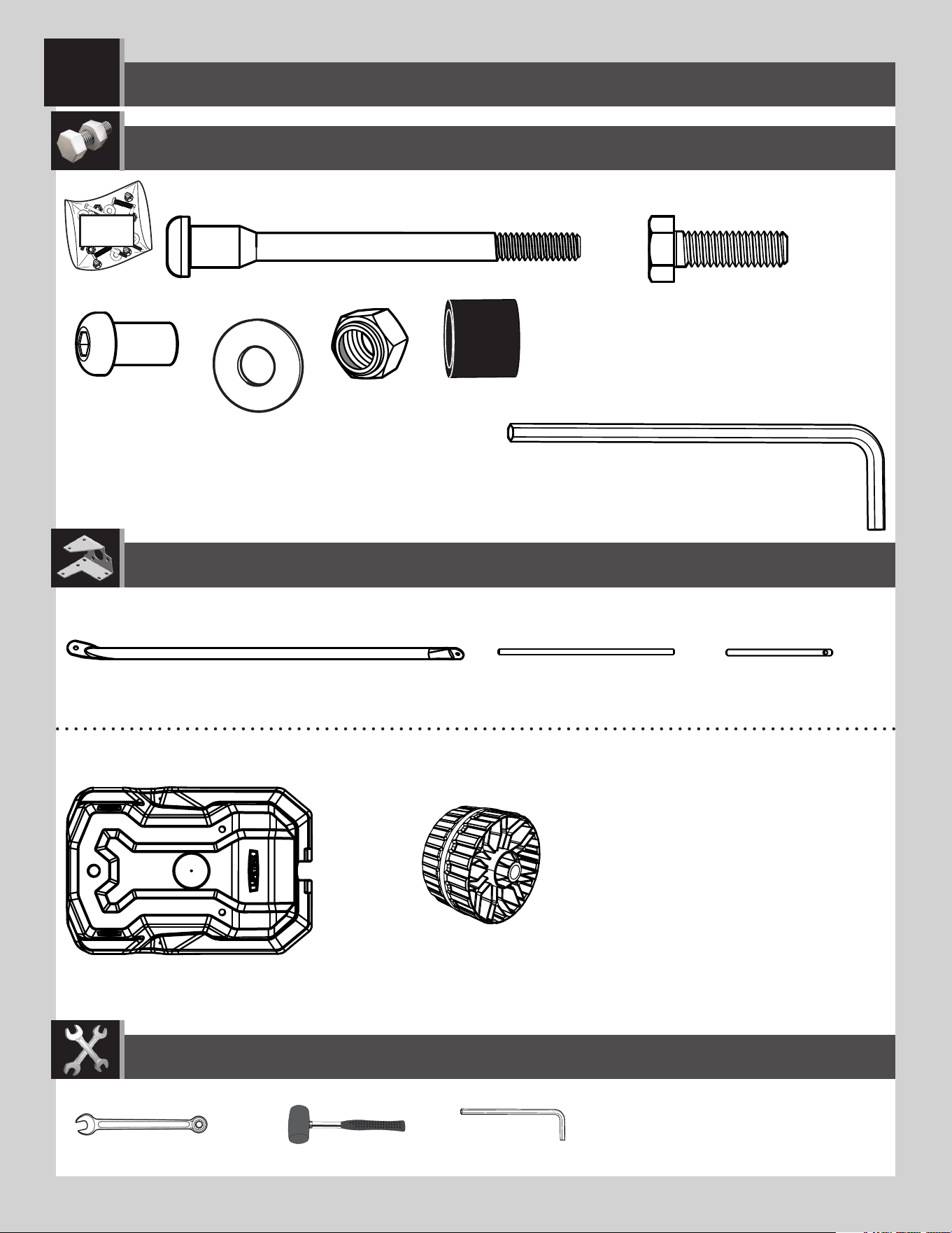
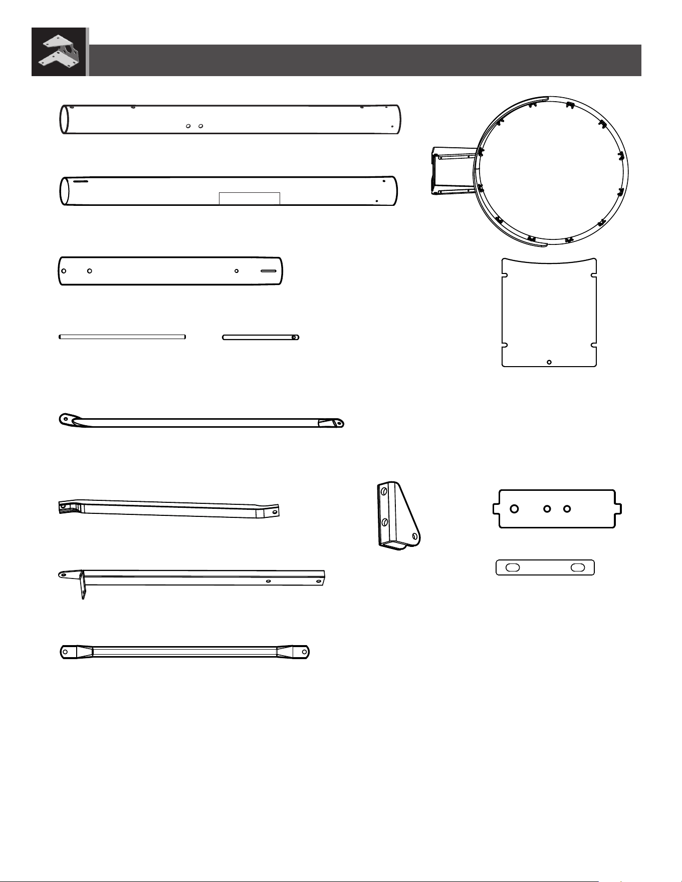
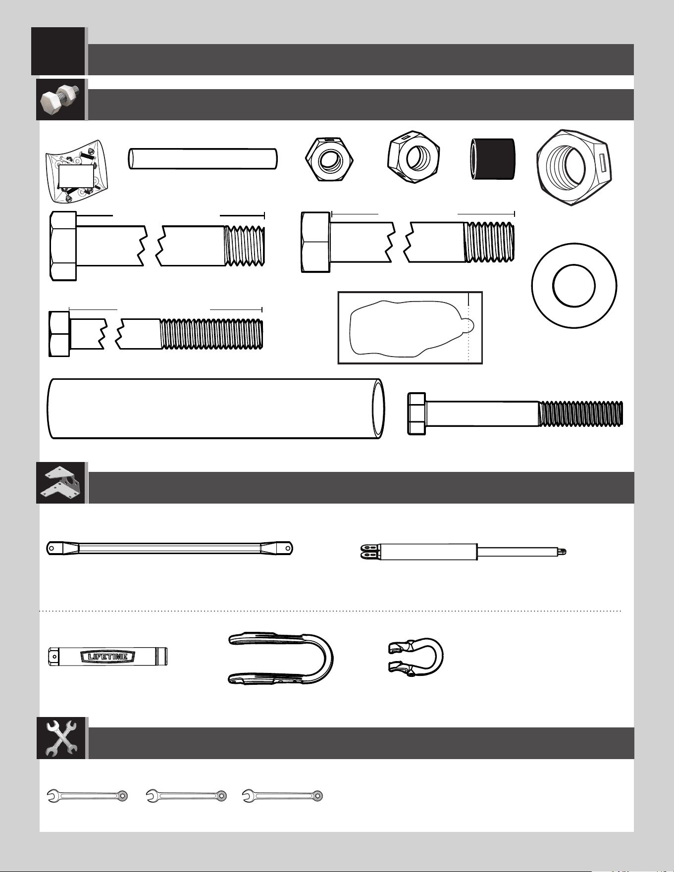
BCO
Metal Parts
TOOLS REQUIRED
PARTS REQUIRED
HARDWARE REQUIRED
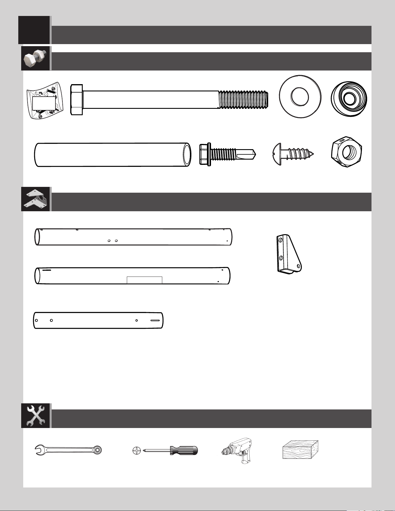
POLE ASSEMBLY
1
ADS (x2)
ABZ (x2)
ABB (x2)
AAF (x2)
ABE (x2)
ABR (x2)
ALH (x1)
Warning Sticker
ALL (x1)
9/16” (≈14 mm)
CIH (x2)
(x2) (x1)
(x1)
(x1)
ALF (x1)
ALE (x1)
5
TOOLS AND HARDWARE REQUIRED
SECTION 1 (CONTINUED)
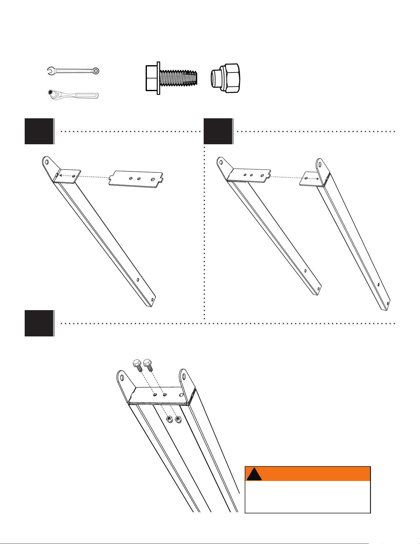
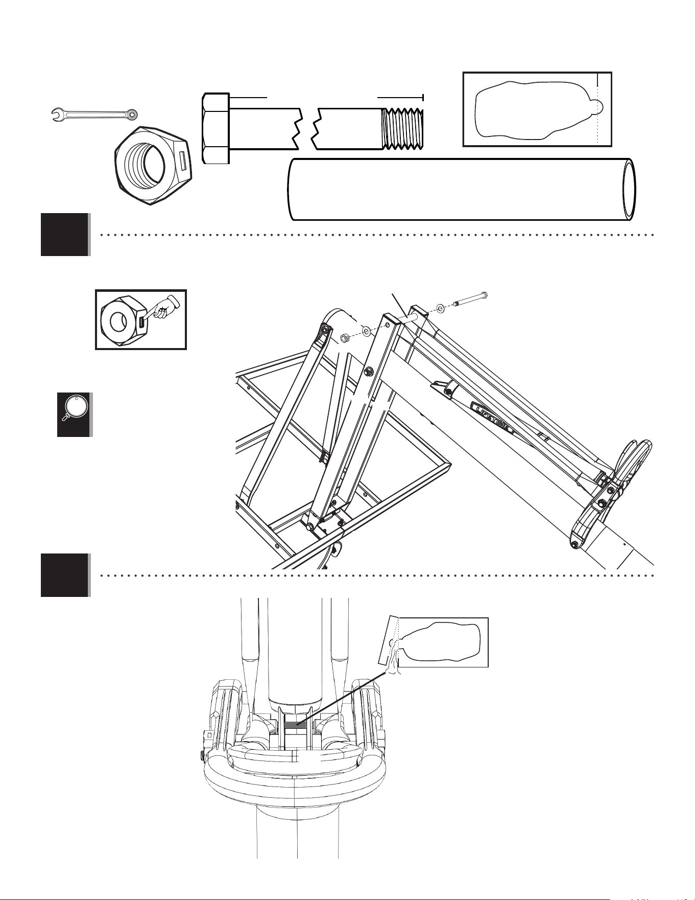
• Insert the Hex Bolts (ABE) with the Washers (AAF) into the
Top Pole (ALH) as shown. Then slide the Spacers (ABR)
onto the Hex Bolts.
1.1
ALH
ABE
ABR
AAF
Large Holes
Small Holes
AAF (x2)
ABE (x2)
ABR (x2)
9/16"
(≈14 mm)
ABB (x2)
• Secure the Pole Bracket (ALL) to the Top Pole with
the hardware as shown.
ALL
ABB
ABE
1.2
(x2)
6
TOOLS AND HARDWARE REQUIRED
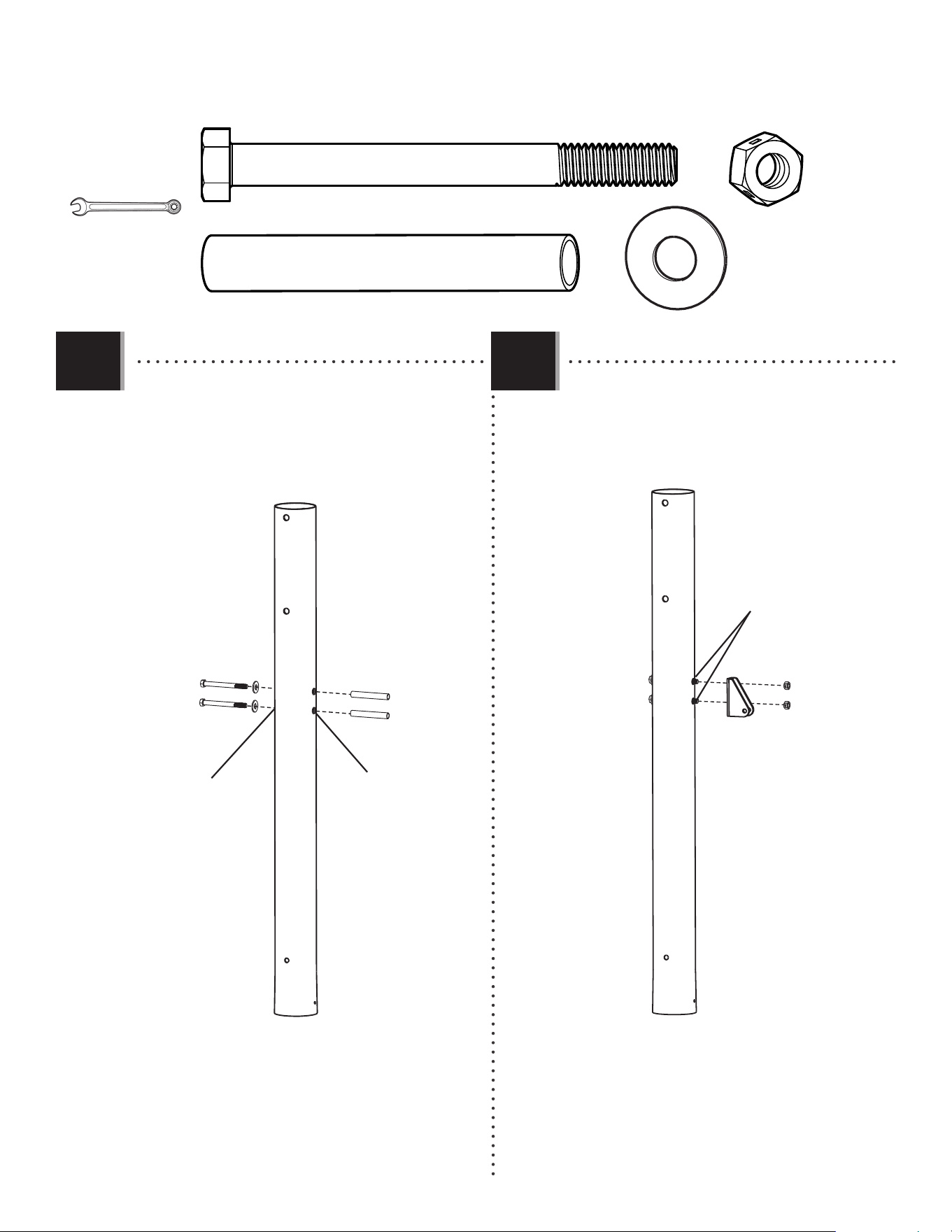
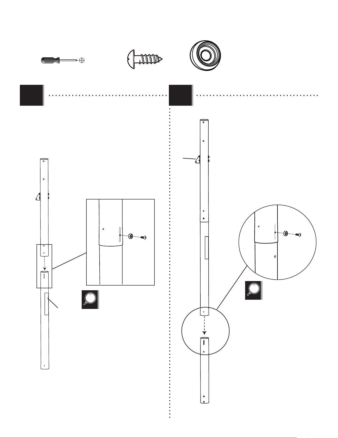
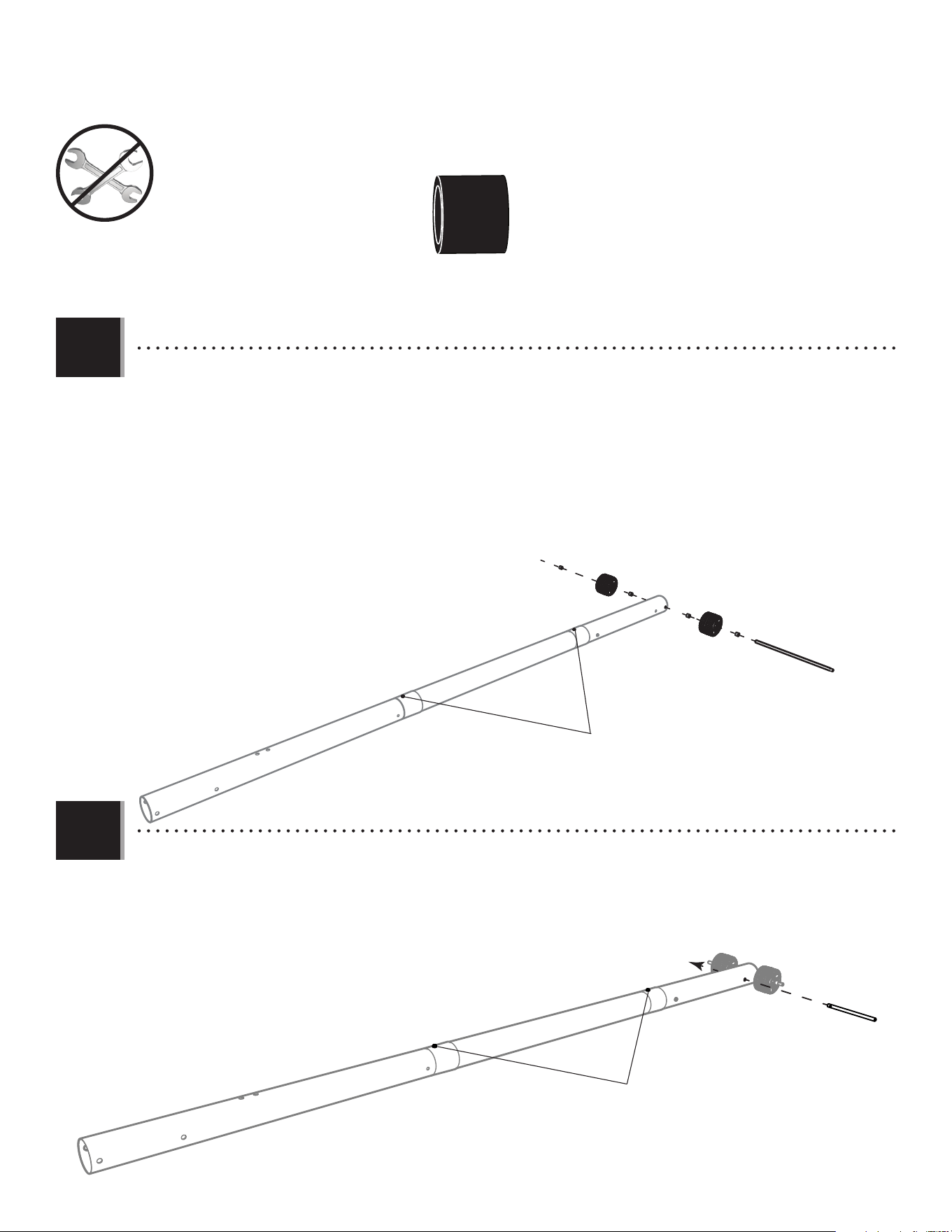
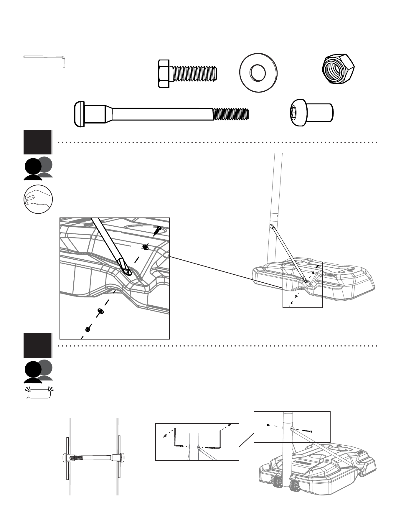
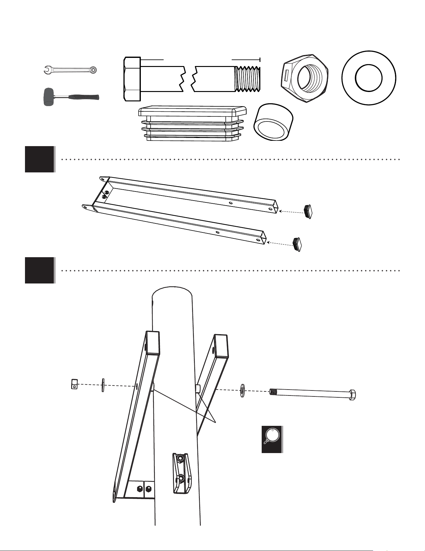
• Align the hole in the bottom of the Top Pole (ALH)
with the slot in the top of the Middle Pole (ALF). Insert
a Screw (ADS) through the Countersink Washer (CIH)
and into the small hole in the Top Pole.
• Secure the Middle Pole to the Bottom Pole (ALE) using
the same method as step 1.3.
1.3
SECTION 1 (CONTINUED)
ADS (x2)
1.4
• The Screw should be fl ush
with the Pole, but will spin
freely once inserted.
ALH
ALF
Warning
Sticker
ADS
ALF
ALH
CIH
ALH
ALF
ALE
ADS
ALE
ALF
CIH
ALL
• The Screw should be fl ush with
the Pole, but will spin freely once
inserted.
CIH (x2)
(x1)
7
TOOLS AND HARDWARE REQUIRED
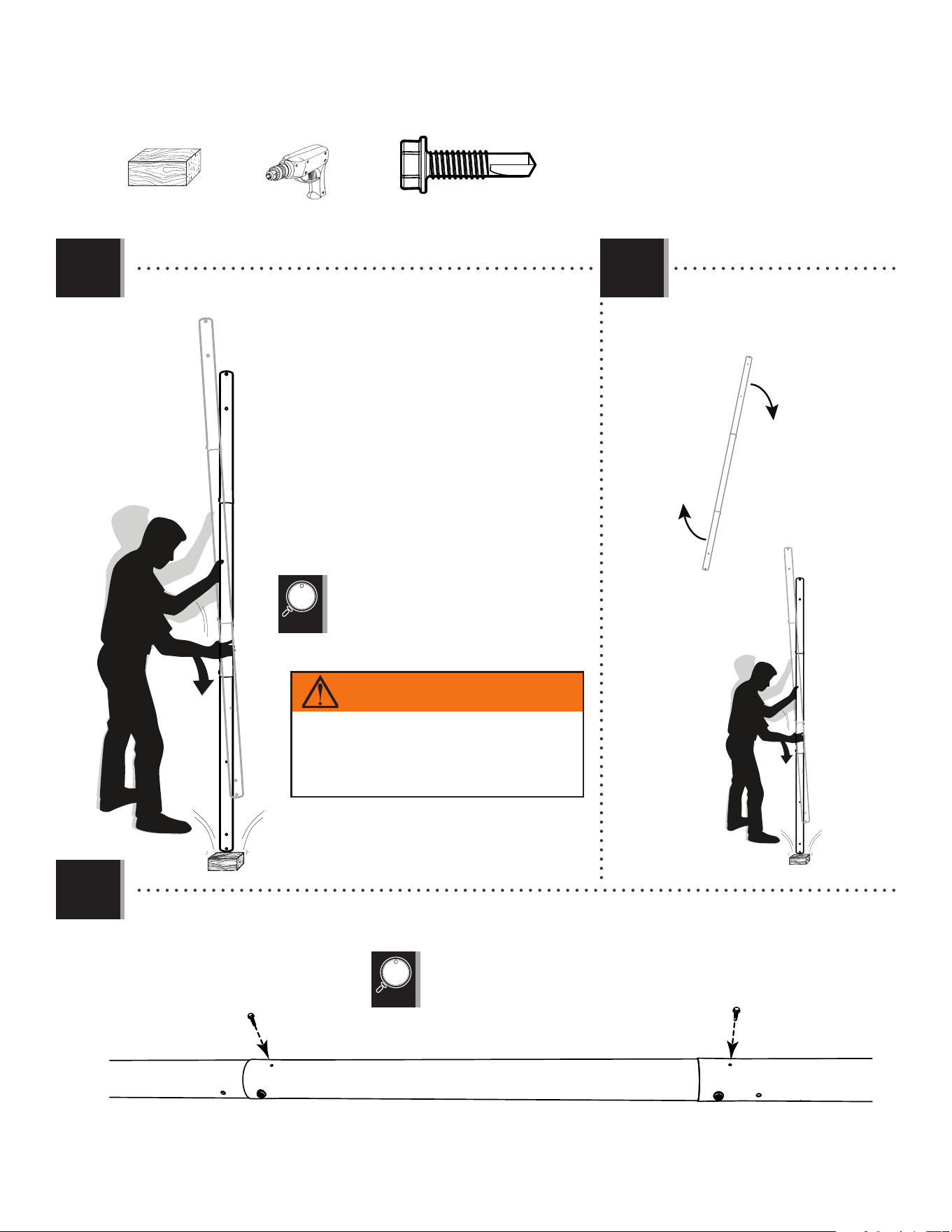
• Strike the end of the Pole Assembly on a piece of scrap wood or
cardboard 5–6 times.
1.5
SECTION 1 (CONTINUED)
6x
• Do not strike your feet with the Pole sections, as
serious injury may occur.
ABZ (x2)
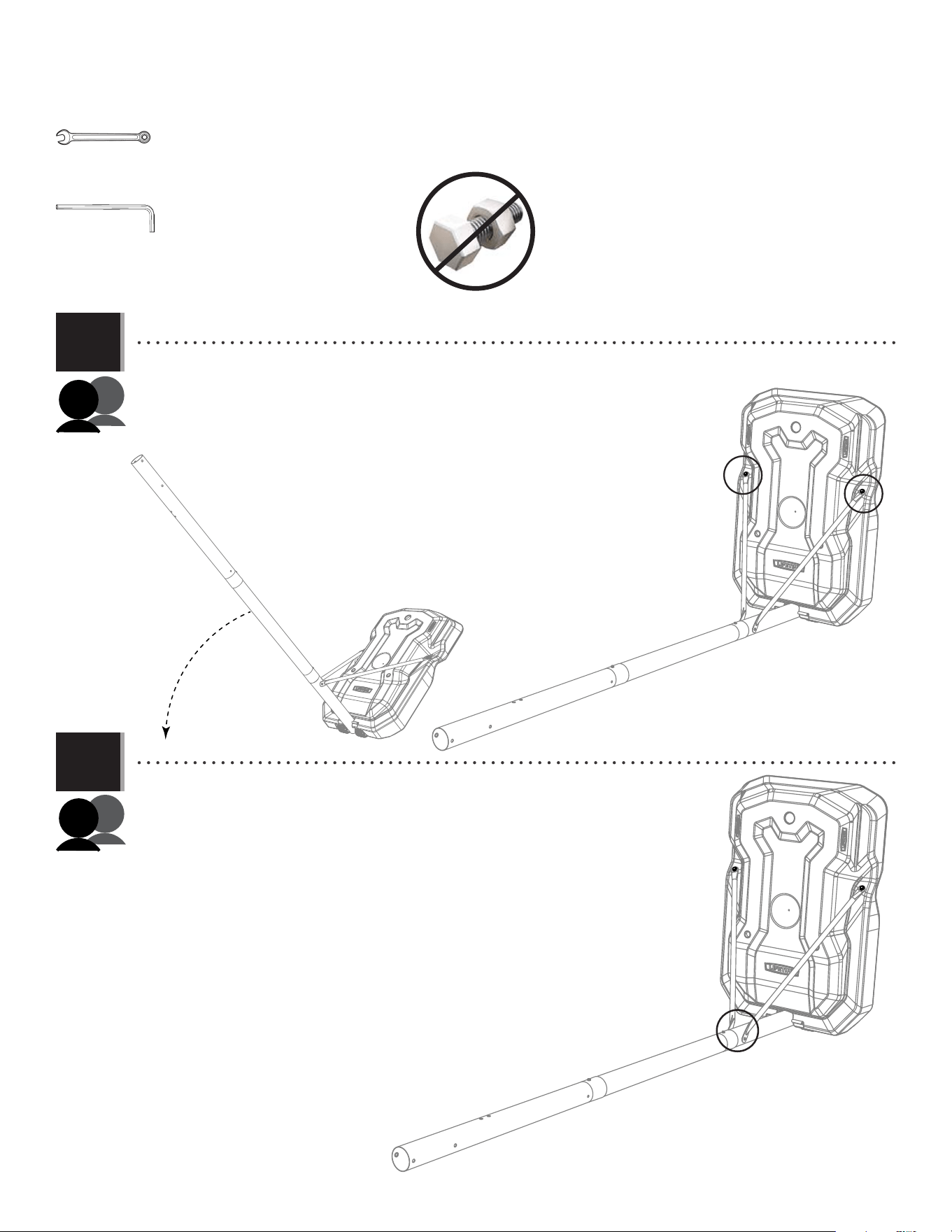
• For ease of installation, chuck the head of
the Self-Tapping Screws directly into the
drill, or use a 3/8” Hex Driver
• Using a Power Drill, secure the Poles together with Self-Tapping Screws (ABZ).
1.7
6x
ALH
ALF
ALE
ABZ
ABZ
WARNING
The poles must be seated together! Even if the poles cover
the slots before seating, they must be struck on a hard
surface five to six times! Failure to seat the poles correctly
could allow the poles to separate during use, which could
lead to serious personal injuries or property damage.
• Flip the Pole over and repeat
step 1.5 for the opposite end
of the Pole Assembly.
1.6
(x1) (x1)
8
POLE-TO-BASE ASSEMBLY / ASSEMBLAGE DU POTEAU A LA BASE / ENSAMBLAJE DEL POSTE A LA BASE
2
BCQ
Metal Parts / Pièces en métal / Piezas de metal
TOOLS REQUIRED / OUTILS REQUIS / INSTRUMENTAL REQUERIDO
PARTS REQUIRED / PIÈCES REQUISES / PIEZAS REQUERIDAS
HARDWARE REQUIRED / QUINCAILLERIE REQUISE / HERRAJE REQUERIDO
AAE (x2)
BTS (x1)
ABD (x4)
AAO (x2)
EEO (x2)
AMU (x2)
AJM (x1)
Plastic Parts / Pièces en plastique / Piezas de plástico
(x2) (x1)
3/16" (≈5 mm)
(x2)
AJC (x1)
HJX (x1)
ABL (x4)
ALI (x2)
DRZ (x1)
1/2" (≈13 mm)
(Not actual size)
(Pas à l’échelle)
(No a la escala)
Axle / Essieu / Eje Axle / Essieu / Eje
9
TOOLS AND HARDWARE REQUIRED / OUTILS ET QUINCAILLERIE REQUIS / INSTRUMENTAL Y HERRAJE REQUERIDOS
SECTION 2 (CONTINUED) / SECTION 2 (SUITE) / SECCIÓN 2 (CONTINUACIÓN)
2.1
2.2
• Lay the pole assembly down and slide the long axle (AJC) through a spacer (ABL), a wheel (AMU), a second spacer (ABL) and the
hole at the end of the bottom pole. Continue sliding the axle through a third spacer (ABL), the second wheel (AMU) and a fourth
spacer (ABL) as indicated. The ends of the axle should be equidistant from the center of the pole.
• Mettre l’assemblage du poteau sur le sol et faire glisser l’essieu long (AJC) à travers une entretoise (ABL), une roue (AMU), une
deuxième entretoise (ABL) et le trou au bas du poteau inférieur. Continuer a faire glisser l’essieu à travers une troisième
entretoise (ABL), la deuxième roue (AMU) et une quatrième entretoise (ABL) comme indiqué. Les extrémités de l’essieu doivent être
équidistantes du centre du poteau.
• Colocar el conjunto del poste en el suelo y faire glisser el eje largo (AJC) a través un espaciador (ABL), una rueda (AMU), un
segundo espaciador (ABL) y el agujero al fondo del poste. Continuar deslizando el eje a través de un tercer espaciador (ABL),
la segunda rueda (AMU) y un cuarto espaciador (ABL) como se indica. Los extremos del eje deben set ends of the axle should be
equidistantes del centro del poste.
• Slide the short axle (HJX) through hole next to the bottom hole so the ends of the axle are equidistant from the pole. Please
note that the two self-tapping screws from step 1.6 are on top.
• Faire glisser l’essieu court (HJX) à travers le trou à côté du trou inférieur pour que les extrémités de l’essieu soient
équidistantes du poteau. Vouloir noter que les deux vis autotaraudeuses de l’étape 1.6 se trouvent en haut.
• Deslizar el eje corto (HJX) a través del orifi cio junto al orifi cio inferior para que los extremos del eje estén equidistantes del
poste. Tenga en cuenta que los dos tornillos autorroscantes del paso 1.6 miran hacia arriba.
ABL
ABL
AMU
AMU
ABL
ABL
AJC
ABL (x4)
HJX
Self-tapping screws
Vis autotaraudeuses
Tornillos autorroscantes
Self-tapping screws
Vis autotaraudeuses
Tornillos autorroscantes
10
TOOLS AND HARDWARE REQUIRED / OUTILS ET QUINCAILLERIE REQUIS / INSTRUMENTAL Y HERRAJE REQUERIDOS
SECTION 2 (CONTINUED) / SECTION 2 (SUITE) / SECCIÓN 2 (CONTINUACIÓN)
AJM
Self-tapping screws
Vis autotaraudeuses
Tornillos autorroscantes
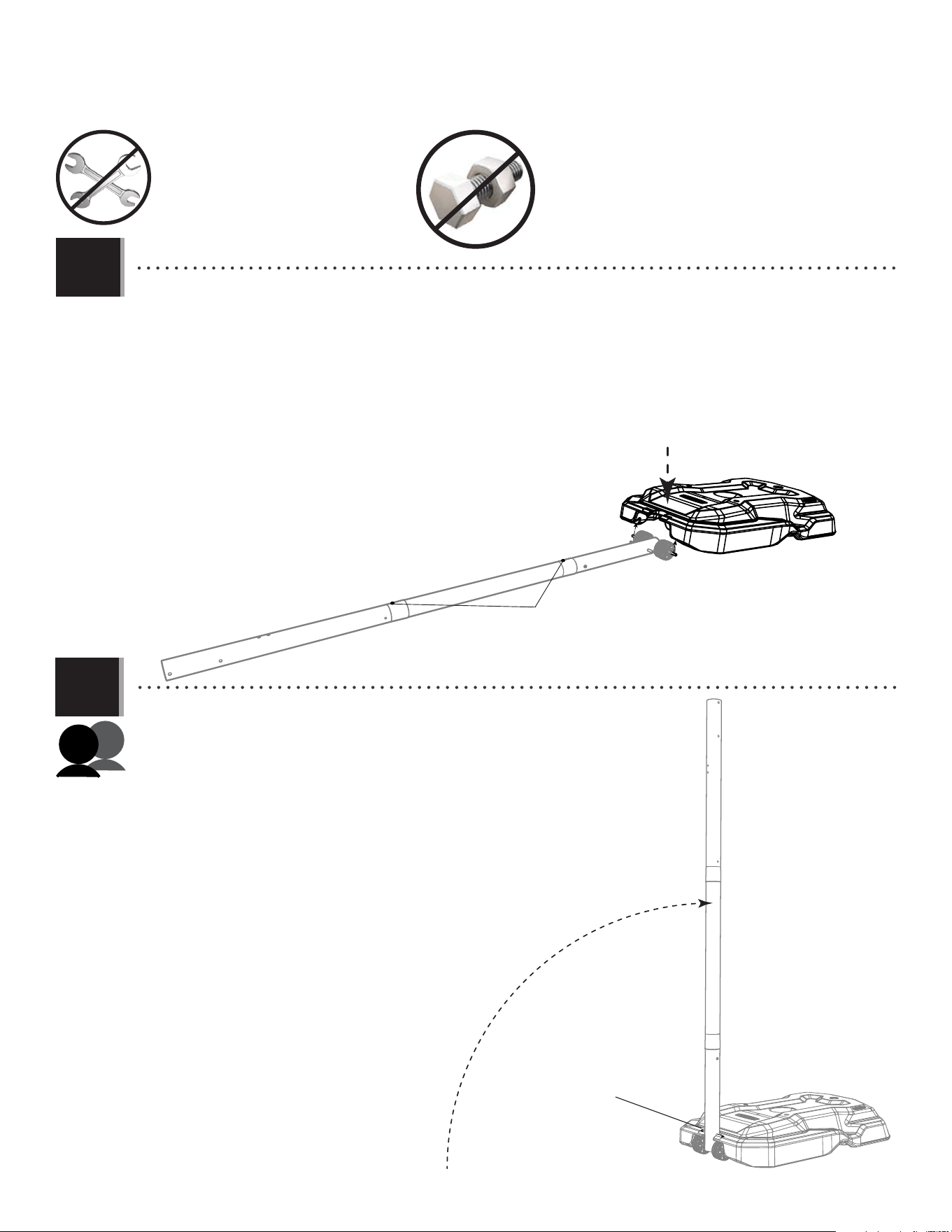
• Set the front of the base (AJM) over the long axle as indicated. The ends of the long axle should be up inside the recesses in
the bottom of the base. Please note that the two self-tapping screws from step 1.6 are on top. These should be on top in order to have all the
other holes in the pole sections oriented correctly.
• Mettre la parte frontale de la base (AJM) sur l’essieu long comme indiqué. Les extrémités de l’essieu long doivent être
dedans les rainures dans la partie inférieure de la base. Vouloir noter que les deux vis autotaraudeuses de l’étape 1.6 se trouvent en
haut. Ceux-ci doivent être sur le dessus afi n que tous les autres trous des sections de poteau soient correctement orientés.
• Colocar la parte delantera de la base (AJM) sobre el eje largo como se indica. Los extremos del eje largo deben estar dentro
de los huecos en la parte inferior de la base. Tenga en cuenta que los dos tornillos autorroscantes del paso 1.6 miran hacia arriba. Estos
deben estar en la parte superior para que todos los demás orifi cios en las secciones del poste estén orientados correctamente.
2.3
2.4
• Rotate the pole assembly upright until the short axle rests in the recess on top of the base.
• Lever l’assemblage du poteau à la verticale jusqu’à ce que l’essieu court repose dans la
partie supérieure de la base.
• Levantar el conjunto del poste vertical hasta que el eje corto se quede en el hueco en la
parte superior de la base.
Short axle
Esseau court
Eje corto
11
TOOLS AND HARDWARE REQUIRED / OUTILS ET QUINCAILLERIE REQUIS / INSTRUMENTAL Y HERRAJE REQUERIDOS
SECTION 2 (CONTINUED) / SECTION 2 (SUITE) / SECCIÓN 2 (CONTINUACIÓN)
2.5
2.6
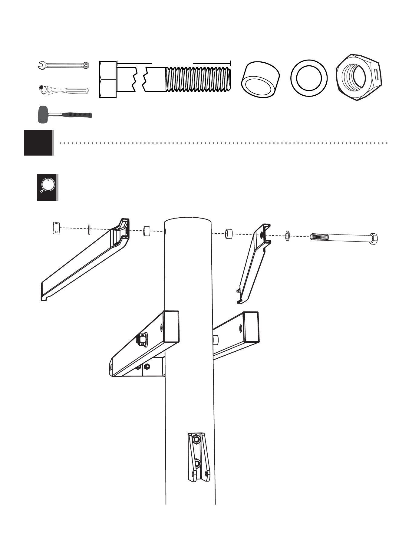
• While a second adult holds the pole upright, attach a pole brace (ALI) to the base as
indicated. Tighten only by hand at this time. Repeat this step for the second pole brace on the
other side of the pole and base.
• Pendant qu’un deuxième adulte tient le poteau a la verticale, attacher un support
de poteau (ALI) a la base comme indiqué. Serrer seulement a la main en ce moment. Répéter
cette étape pour le deuxième support de poteau sur l’autre côté du poteau et de la base.
• Mientras un segundo adulto sostiene el poste en posición vertical, sujetar un
soporrte de poste (ALI) a la base come se indica. Apretar sólo a mano en este momento.
Repetir este paso para el segundo soporte de poste en el otro lado del poste y de la base.
• Align the holes in the braces with those in the pole and secure the braces to the pole using the hardware indicated. Note the
bolt (DRZ) does not go all the way through the pole; the barrel nut (BTS) connects to it inside the pole. DO NOT completely tighten at this time.
• Aligner les trous dans les supports avec ceux dans le poteau et fi xer les supports au poteau en utilisant la quincaillerie
indiquée. Notar que le boulon (DRZ) ne traverse pas complètement le poteau ; l’écrou à manchon (BTS) s’y connecte à l’intérieur du poteau. NE
PAS serrer complètement en ce moment.
• Alinear los orifi cio en los soportes con ellos en el poste y fi jar los soportes al poste usando el herraje indicado. Observar que el
perno (DRZ) no atraviesa por completo el poste; la tuerca de acoplamiento (BTS) se conecta a ello dentro del poste.
• NO apretar por completo en este momento.
AAE (x2)
ABD (x4)
AAO (x2)
AAO
ABD
ABD
ALI
ALI
AAE
BTS (x1)
DRZ (x1)
DRZ
BTS
“$#@*%!”
THIS STEP CAN BE DIFFICULT
DSA
BTS
EEO (x2)
12
TOOLS AND HARDWARE REQUIRED / OUTILS ET QUINCAILLERIE REQUIS / INSTRUMENTAL Y HERRAJE REQUERIDOS
SECTION 2 (CONTINUED) / SECTION 2 (SUITE) / SECCIÓN 2 (CONTINUACIÓN)
2.7
2.8
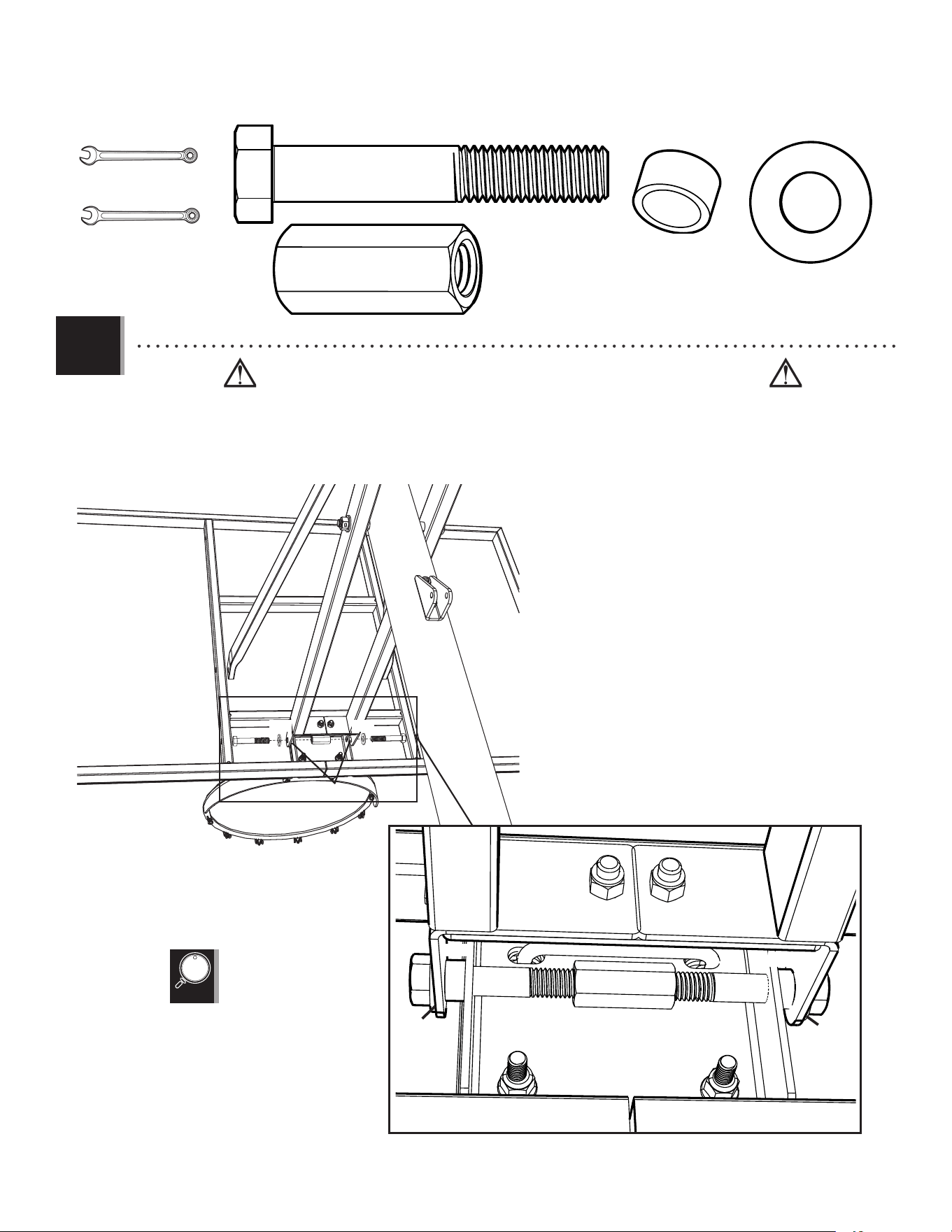
• Lay the system down and keep it down until instructed otherwise. Securely tighten the hardware
indicated. DO NOT overtighten.
• Poser le système sur le sol et le maintenir jusqu’à instruction contraire. Bien serrer la quincaillerie
indiquée. NE PAS trop serrer.
• Colocar el sistema en el suelo y guardarlo así hasta que se le indique lo contrario. Apretar bien el
herraje indicado. NO apretar demasiado.
• Now, securely tighten the hardware from step 2.6.
• Maintenant, bien serrer la quincaillerie de l’étape 2.6.
• Ahora, apretar bien el herraje del paso 2.6.
1/2" (≈13 mm)
(x2)
EEO (x2)
13
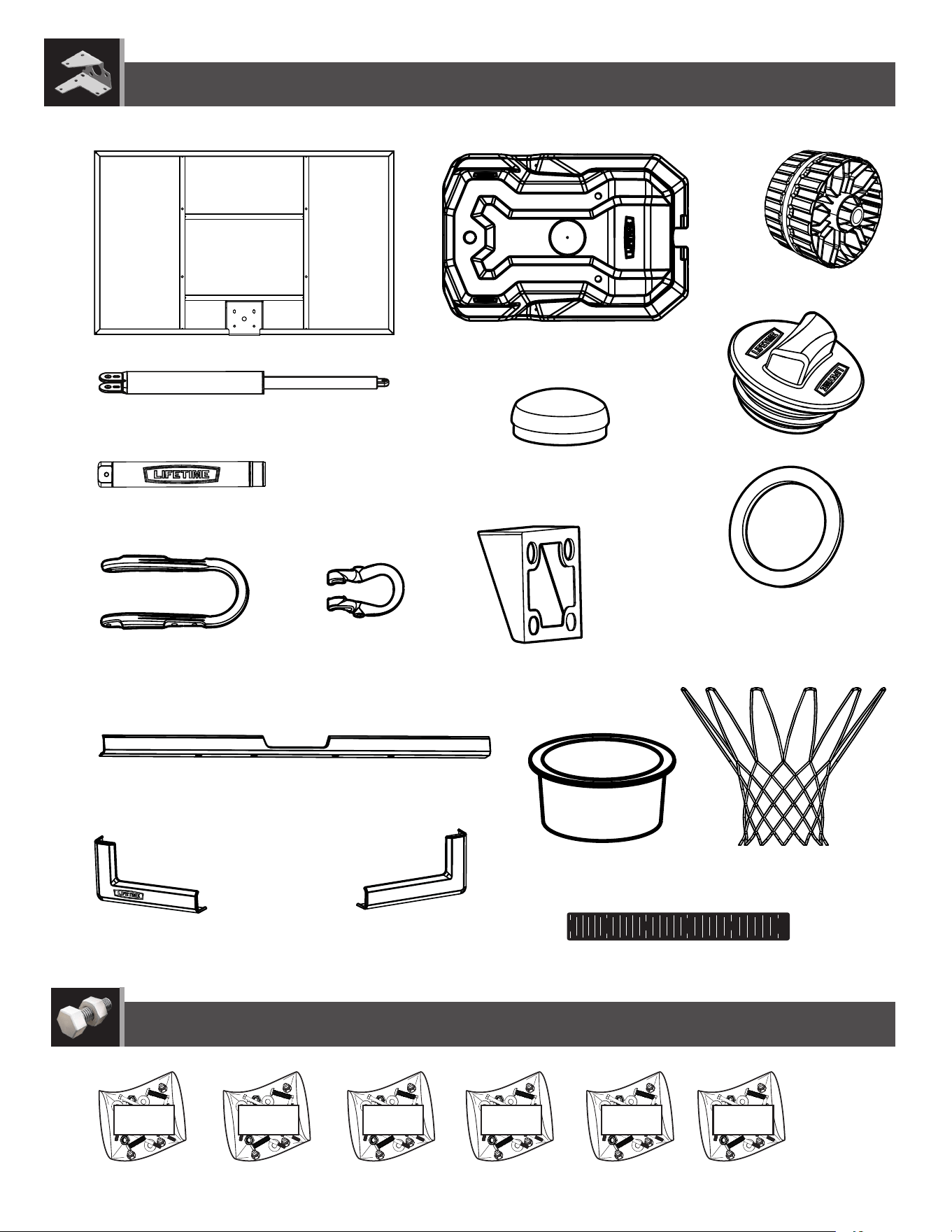
BACKBOARD-TO-RIM ASSEMBLY
3
BCS
Metal Parts
Hardware Bag
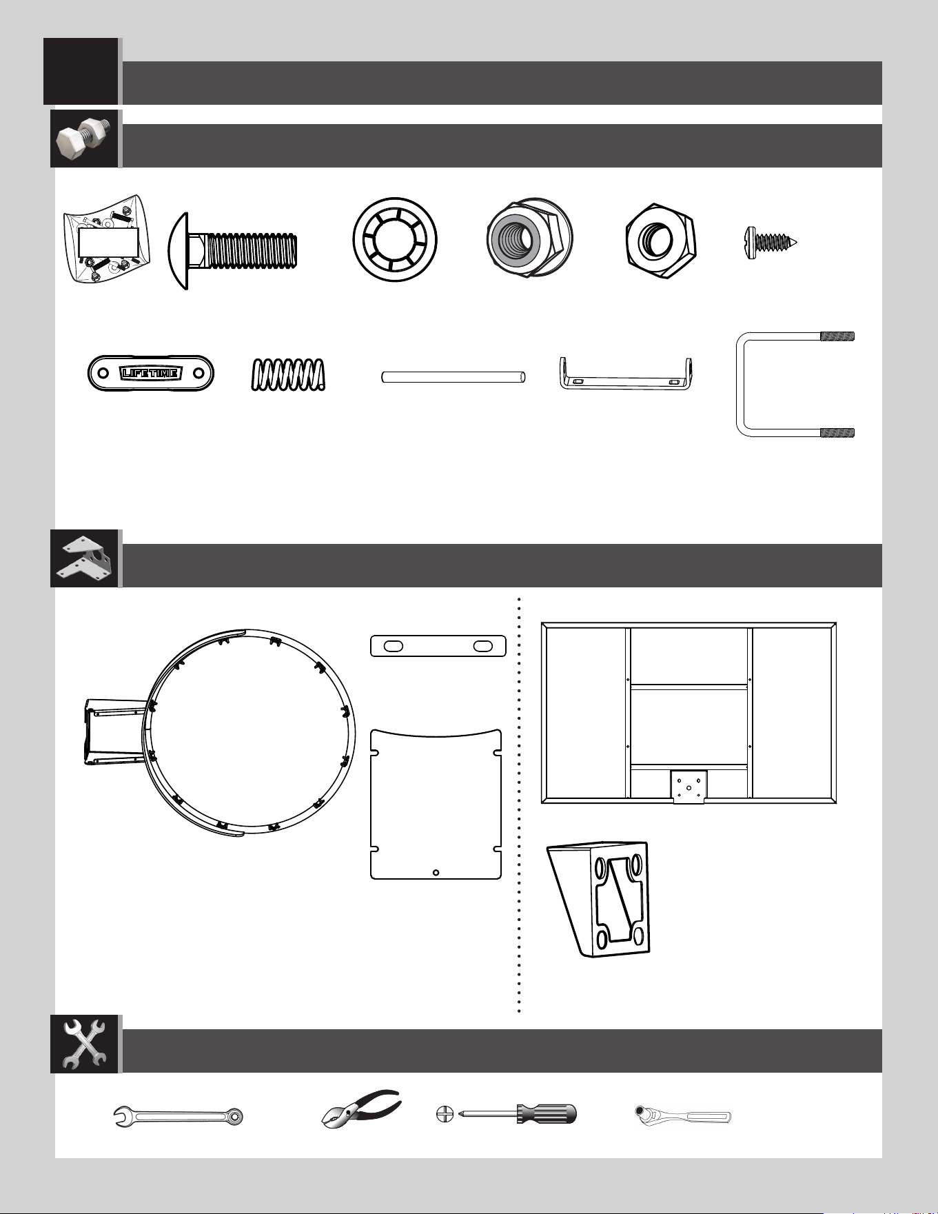
PARTS REQUIRED
HARDWARE REQUIRED
AJI (x1)
ALD (x1)
Plastic Parts
TOOLS REQUIRED
(x2)
1/2” (13 mm)
EAP (x2) AAQ (x2)
ABK (x4)
AAV (x2)
ADR (x4)
AJW (x2)
APZ (x1)
AOW (x1)
APY (x1)
ABQ (x1)
ALX (x1)
AMA (x1)
BGR (x1)
(x1)
(x1)
1/2” (13 mm)
(x1)
14
TOOLS AND HARDWARE REQUIRED
SECTION 3 (CONTINUED)
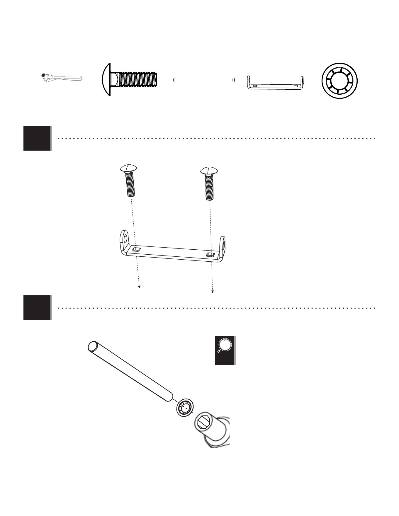
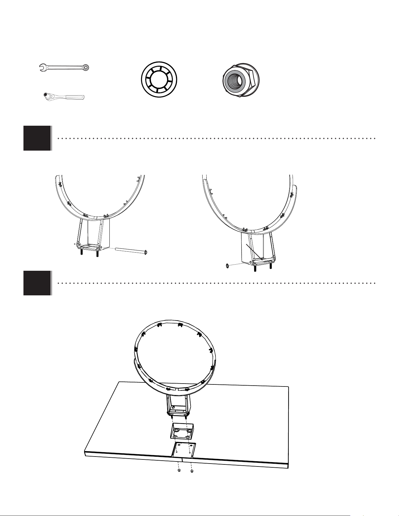
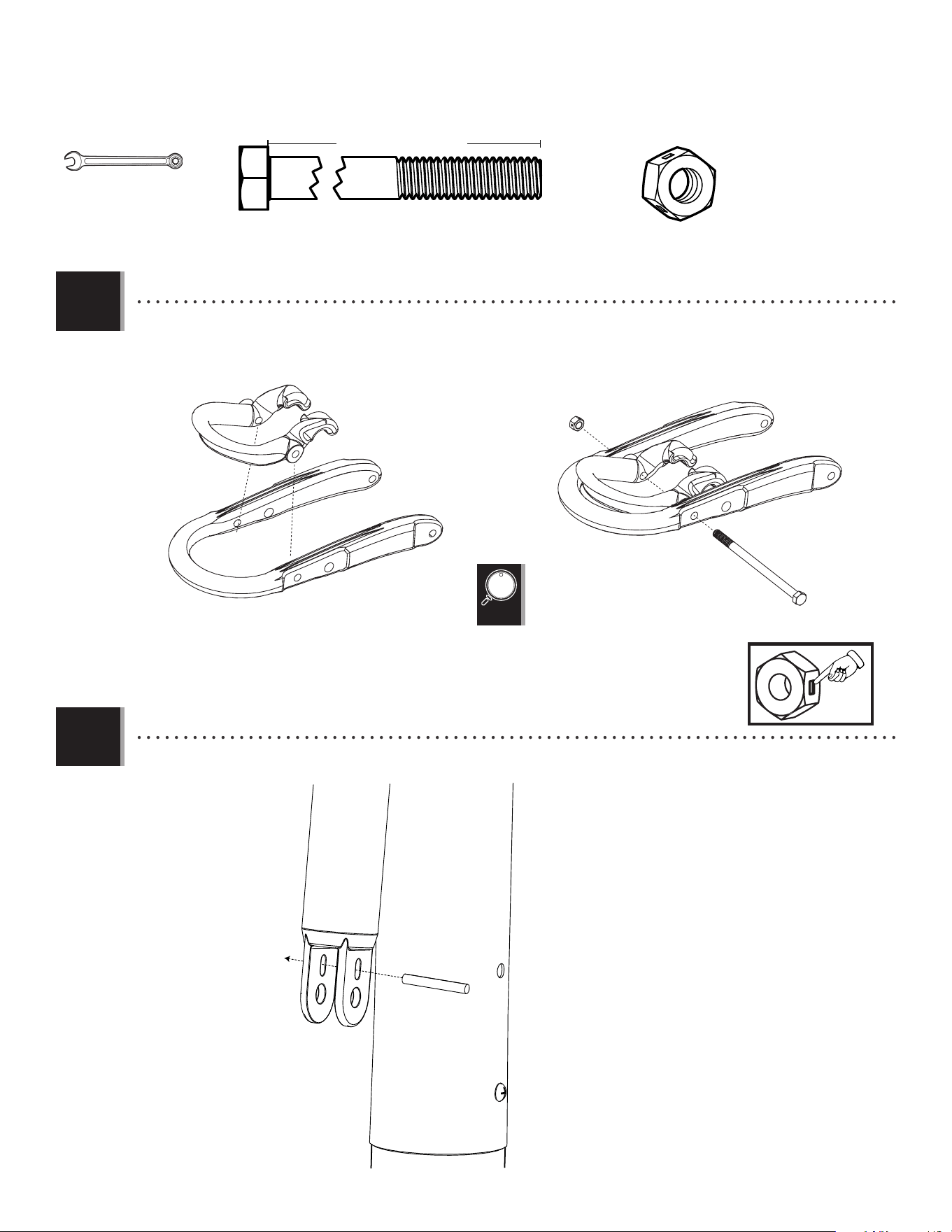
3.1
3.2
• Insert two Carriage Bolts (EAP) through the Rim Pivot Bracket (APY) as shown.
• Use the 1/2” socket head from the socket head wrench to press one Push Nut (AAQ) onto one end of the Axle
(ABQ).
(Not to scale)
EAP (x2)
APY (x1)
AAQ (x1)
ABQ (x1)
(Not to scale)
EAP EAP
APY
AAQ
ABQ
1/2” (13 mm)
Socket Head
(x1)
• The Push Nut should rest about 1/8” from the end
of the Axle. If the Push Nut slips on too far, continue
sliding it to the other end of the Axle to remove it
and try again.
!
15
TOOLS AND HARDWARE REQUIRED
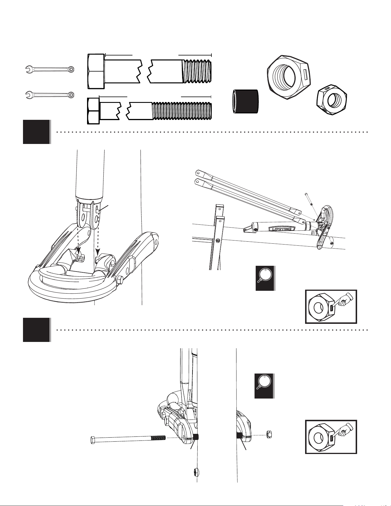
SECTION 3 (CONTINUED)
3.3
3.4
• Slide the end of the Axle (ABQ) through the Rim (ALX) and the Rim Pivot Bracket (APY). Press the Push Nut (AAQ) onto
the end of the Axle. Use the socket head to secure the Push Nut if needed.
• Connect the Rim and Plastic Guard (ALD) to the Backboard (AJI) with the hardware shown.
1/2” (13 mm)
ABK (x2)AAQ (x1)
1/2” (13 mm)
APY
ALX
ABQ
ABQ
AAQ
ABK
ABK
ALD
AJI
(x1)
(x2)
16
TOOLS AND HARDWARE REQUIRED
SECTION 3 (CONTINUED)
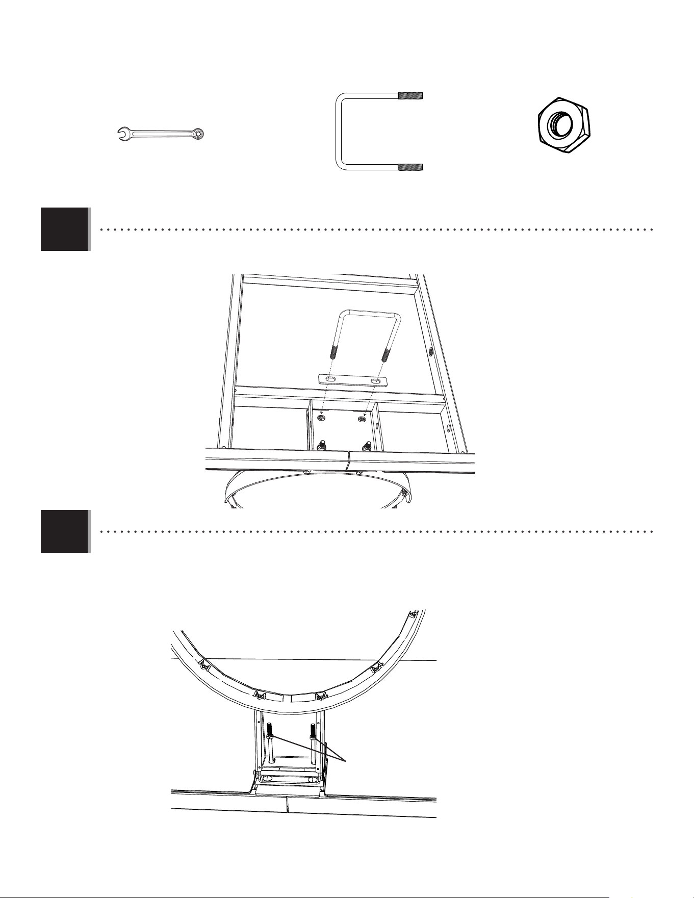
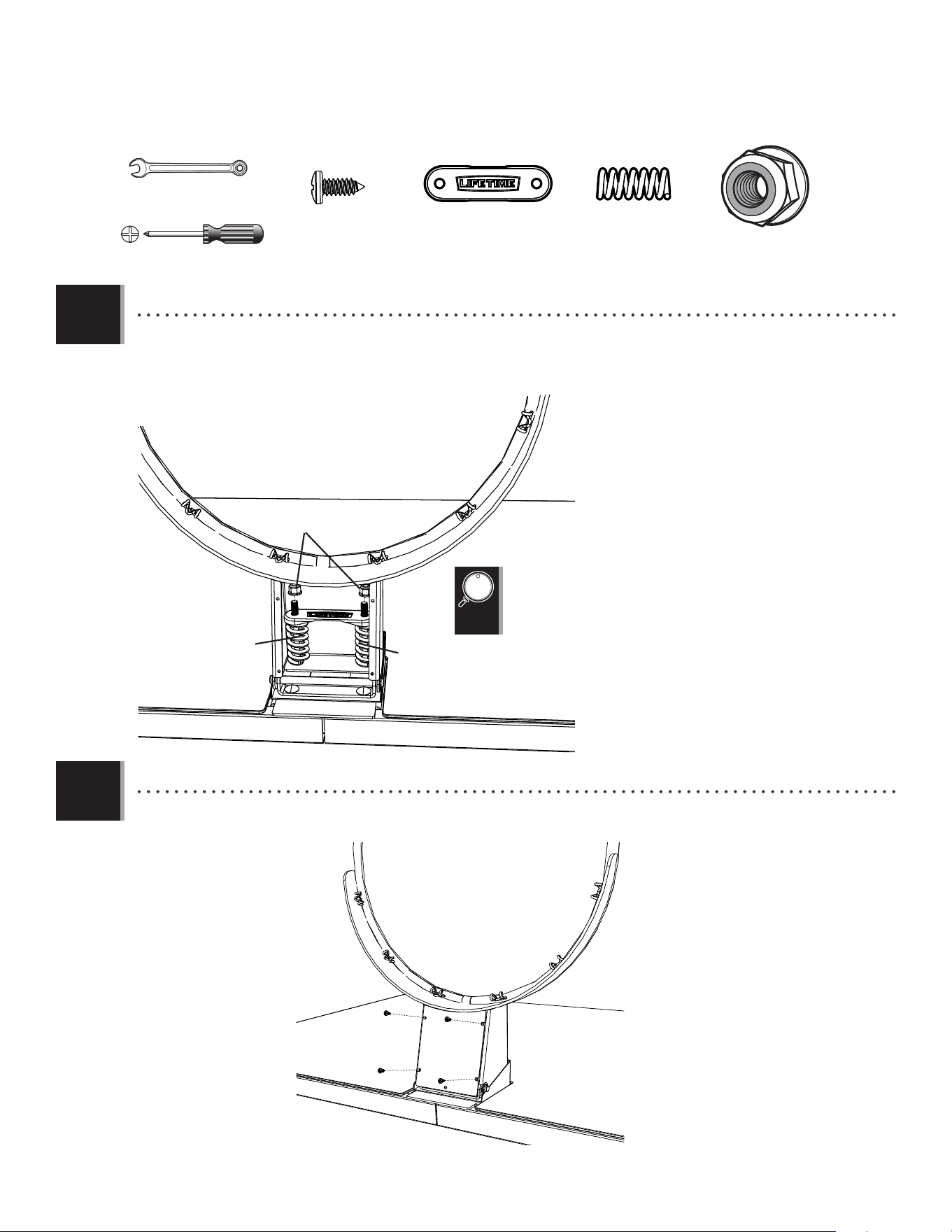
3.5
3.6
• Thread the Jam Nuts (AAV) all the way down on the U-Bolt as shown.
• Insert the U-Bolt (APZ) through the U-Bolt Washer Plate (BGR) and into the back of the Backboard as shown.
APZ (x1)
(Not to scale)
AAV (x2)
1/2” (13 mm)
AAV
APZ
BGR
(x2)
17
TOOLS AND HARDWARE REQUIRED
SECTION 3 (CONTINUED)
3.7
3.8
• Attach the Rim Cover Plate (AMA) to the Rim with the hardware shown.
• Slide the Compression Springs (AJW) onto the U-Bolt, and place the Spring Retainer Plate (AOW) over the Compression
Springs. Tighten the Nylock Flange Nuts (ABK) until the Rim (ALX) does not wobble to complete this step.
ADR (x4)
(Not to scale)
ABK (x2)
AJW (x2)
AOW (x1)
(Not to scale)
1/2” (13 mm)
AJW
AOW
ABK
• DO NOT COMPLETELY TIGHTEN THE NYLOCK
FLANGE NUTS IN THIS STEP! Only tighten the Nuts
until the Rim (ALX) does not wobble. Tightening
the Nuts will adjust the Rim tension.
!
ADR
ADR
ADR
ADR
AMA
AJW
(x2)
(x1)
18
Metal Parts
PARTS REQUIRED
HARDWARE REQUIRED
BACKBOARD-TO-POLE ASSEMBLY
4
BCR
AAD (x1)
7 1/16 in/po (≈18cm)
(Not actual length)
AAX (x4)
AQB (x2)
AAN (x2)
ABP (x6)
AOR (x6)
AQC (x2)
ANK (x4)
AQD (x1)
5 in/po (≈13cm)
(Not actual length)
ANP (x1)
ANQ (x2)
ANU (x2)
ANS (x8)
BGP (x2)
BGO (x2)
BLC (x1)
Plastic Part
ALM (x1)
TOOLS REQUIRED
3/4”, 1/2” 1/2”, 11/16”,
3/4”
(x2)
19
SECTION 4 (CONTINUED)
TOOLS AND HARDWARE REQUIRED
4.1 4.2
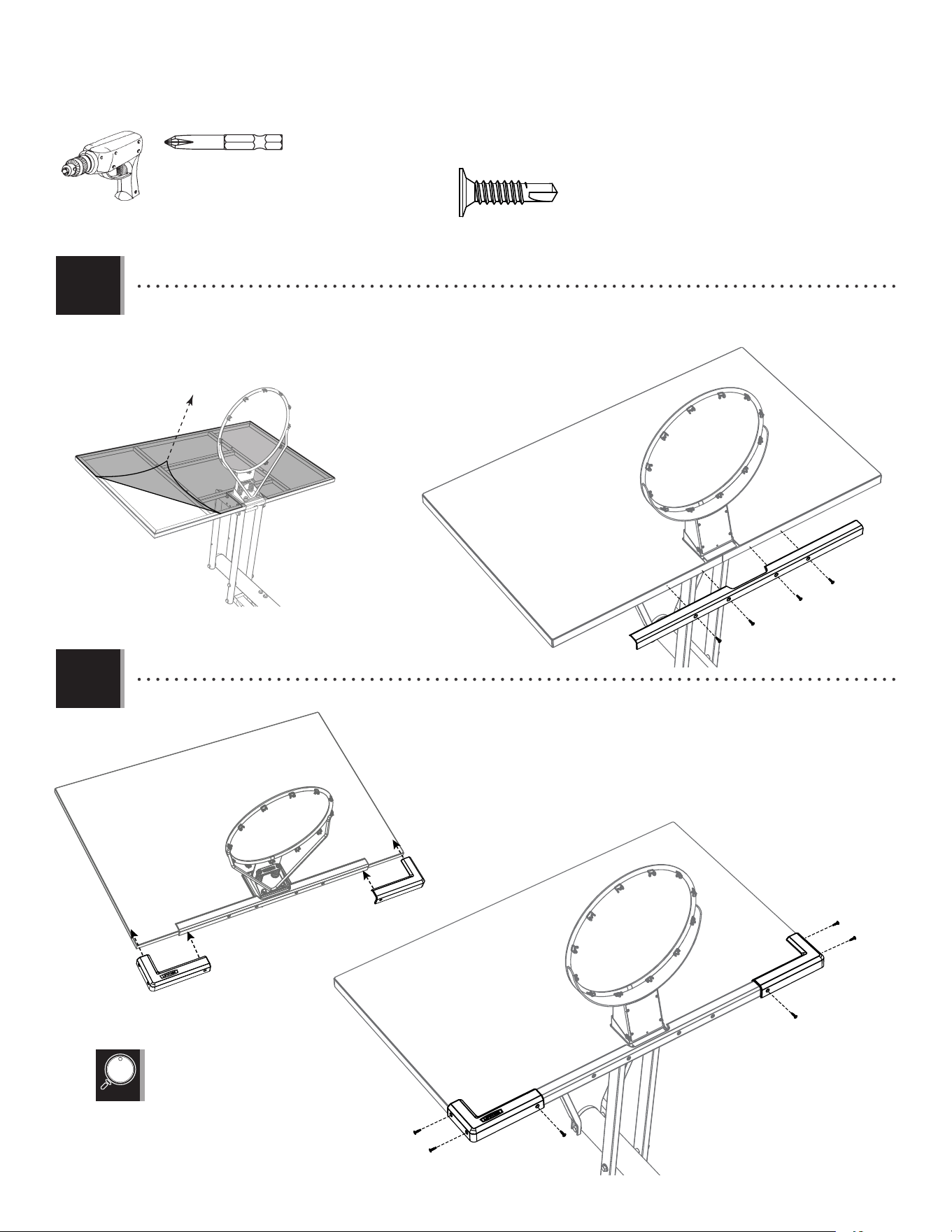
• Insert one end of the Tie Plate (BLC) into the slot
on the Lower Extension Arm (BGP) as shown.
• Insert the opposite end of the Tie Plate into the slot
on the other Lower Extension Arm (BGP) as shown.
BLC
BGP
BGP
4.3
• Attach the Lower Extension Arms (BGP) together with the hardware shown. Use a Socket Wrench to screw the Thread-Cutting
Bolts (AQB) through the Lower Extension Arms and the Tie Plate (BLC).
1/2” (≈13 mm)
1/2” (≈13 mm)
AQB (x2)
AAN (x2)
WARNING
!
Do not overtighten the cap nut. If the end of
the bolt breaks through the plastic cap, call our
Customer Service Department. Exposed threads
on the end of the bolt may cause serious injuries.
AQB
AAN
BGP
BGP
BLC
20
SECTION 4 (CONTINUED)
TOOLS AND HARDWARE REQUIRED
4.6
• Insert the Extension Arm Caps (AQC) into the ends of the Lower Extension Arms as shown.
AAD (x1)
7 1/16 in/po (≈18cm)
(Not actual length)
AAX (x1)
ABP (x2)
AOR (x2)
3/4” (≈19 mm)
AAD
AOR
AOR
AAX
ABP
ALH
4.4
• Tighten the Centerlock Nut (AAX) until
it is fl ush with the end of the Bolt.
(x2)
4.6
• Attach the Lower Extension Arms to the Top Pole (ALH) with the hardware shown.
4.5
AQC (x2)
AQC
AQC

i
This page intentionally left blank
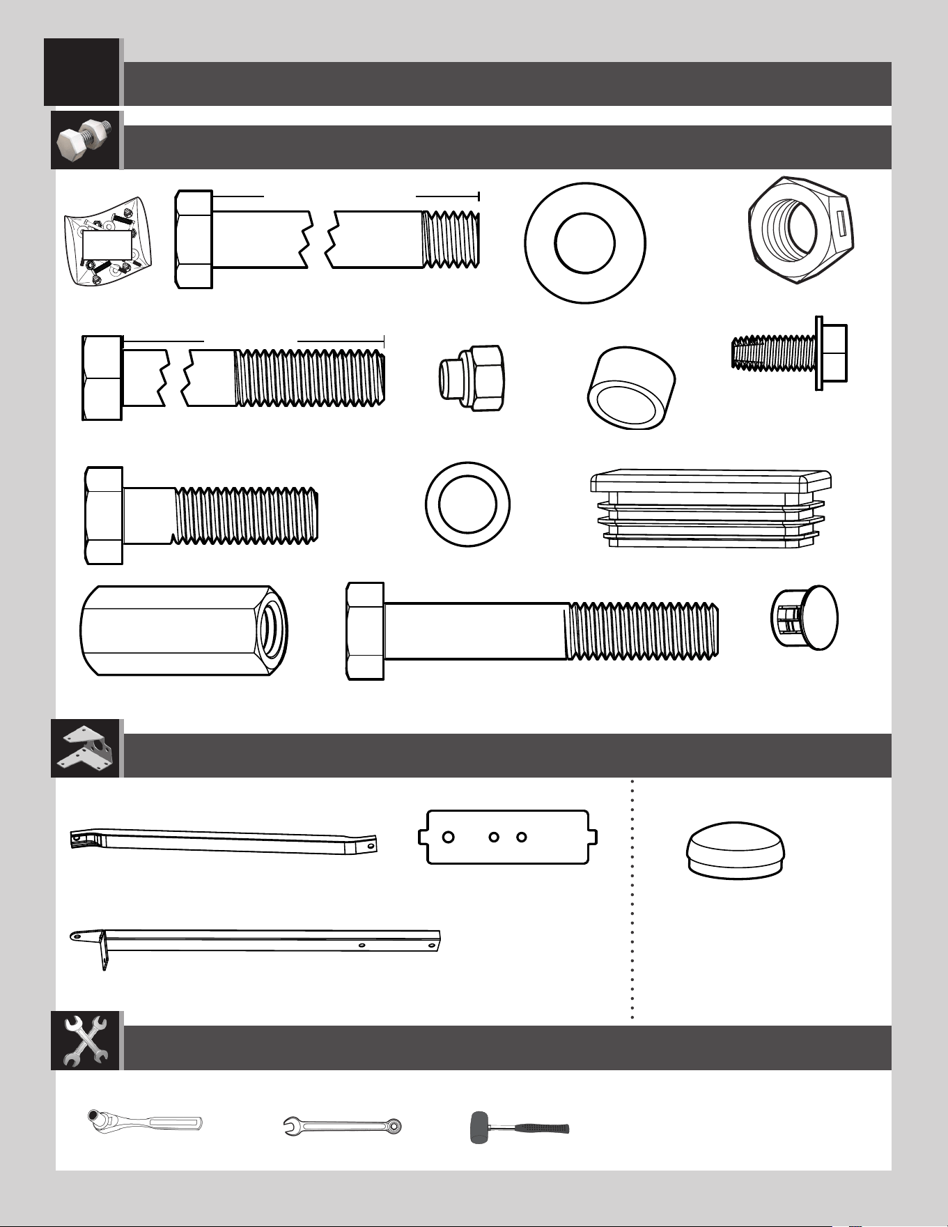
PARTS IDENTIFIER
Remove this yellow section for use as a quick reference
ii
PARTS IDENTIFIER
Metal Parts
ALS (x2)
BGP (x2)
BGO (x2)
BLC (x1)
ALX (x1)
AMA (x1)
BGR (x1)
ALL (x1)
ALE (x1)
ALH (x1)
ALF (x1)
Warning Sticker
Remove this yellow section for use as a quick reference
AJC (x1)
HJX (x1)
ALI (x2)
Axle / Essieu / Eje Axle / Essieu / Eje
iii
PARTS IDENTIFIER
HARDWARE REQUIRED
Plastic Parts
BCO BCQ BCS BCR BCT BCU
AKZ (x1)
AKP (x1)
1109 02 5
10’
9’6”
9’
8’6”
7’6”
8’
AKF (x1)
AKI (x1)
AMN (x1)
AKG (x1)
ALM (x1)
AJI (x1)
ALD (x1)
AMU (x2)
AJM (x1)
FIR (x1)
FIQ (x1)
BAA (x2)
AJQ (x1)
BAB (x1)
Remove this yellow section for use as a quick reference
AEF (x2)

iv
This page intentionally left blank
Remove this yellow section for use as a quick reference
PARTS IDENTIFIER
21
SECTION 4 (CONTINUED)
TOOLS AND HARDWARE REQUIRED
4.6
• Attach the Upper Extension Arms (BGO) to the Top Pole (ALH) with the hardware shown. If necessary, use a Rubber Mallet to tap
the bolt into place.
AQD (x1)
5 in/po (≈13cm)
(Not actual length)
AAX (x1)
ABP (x2)
3/4” (≈19 mm)
ANK (x2)
3/4” (≈19 mm)
AQD
AAX
BGO
ANK
ABP
ABP
ANK
BGO
ALH
• Tighten the Centerlock Nut (AAX) until it
is fl ush with the end of the Bolt.
22
SECTION 4 (CONTINUED)
TOOLS AND HARDWARE REQUIRED
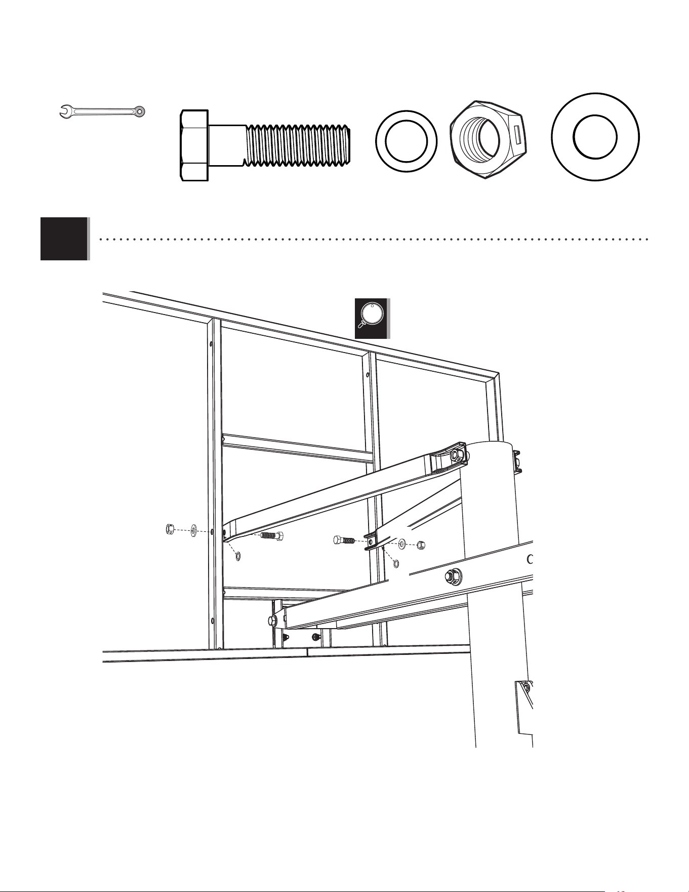
4.7
• Lay the Backboard and Rim assembly next to the Pole assembly. Rest the Rim on cardboard to prevent
scratching. Then secure the Lower Extension Arms (BGP) to the Backboard (AJI) with the hardware shown. Center the
Bolts with Nylon Patches (ANQ) onto the Nut Coupler (ANP) as shown.
• Make sure that the
Plastic Spacers (ABP) do
not bulge.
3/4” (≈19 mm)
ABP (x2)
AOR (x2)
ANP (x1)
ANQ (x2)
11/16” (≈18 mm)
CAUTION: HAVE ONE ADULT HOLD THE BACKBOARD IN PLACE
UNTIL ASSEMBLY HAS BEEN COMPLETED!
BGP
BGP
AJI
ANQ
ANQ
AOR
AOR
ANP
ABP
ANQ
ANQ
AOR
AOR
ANP
ABP
ABP
(x2)
(x2)
23
SECTION 4 (CONTINUED)
TOOLS AND HARDWARE REQUIRED
4.8
• Attach the Upper Extension Arms (BGO) to the Backboard (AJI) with the hardware shown.
3/4” (≈19 mm)
AAX (x2)
ANK (x2)
AOR (x2)
ANU (x2)
• Tighten the Centerlock Nut (AAX) until
it is fl ush with the end of the Bolt.
AAX
AAX
AOR
AOR
ANK
ANK
ANU
ANU
BGO
BGO
(x2)
24
SECTION 4 (CONTINUED)
TOOLS AND HARDWARE REQUIRED
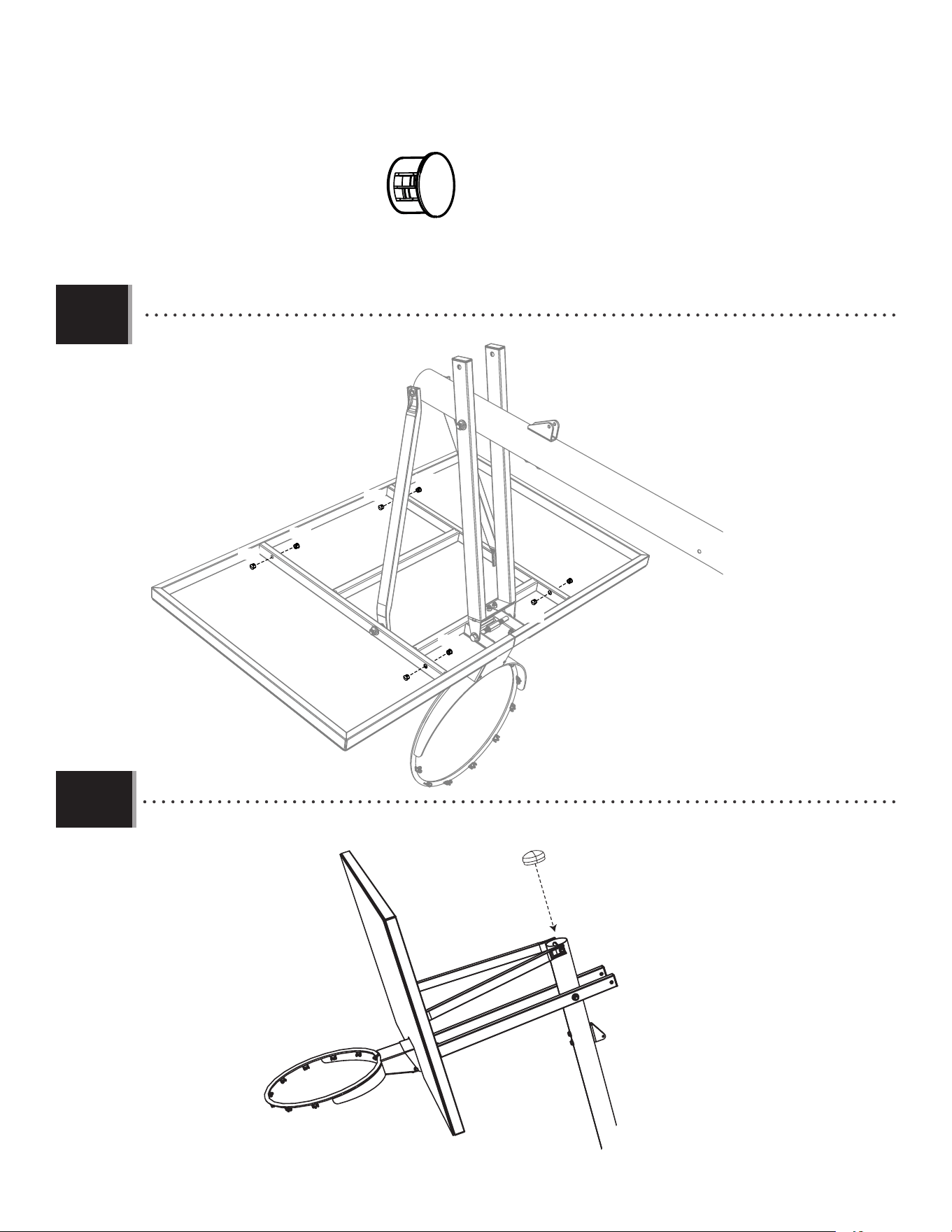
• Insert Nylon Plugs (ANS) into the locations indicated on the back of the Backboard.
• Insert the Pole Cap (ALM) into the end of the Top Pole.
ANS (x8)
ALM
4.9
4.10
ANS
ANS
ANS
ANS
ANS
ANS
ANS
ANS
25
HANDLE ASSEMBLY
5
6 1/2 in/po (≈17cm)
Plastic Parts
PARTS REQUIRED
HARDWARE REQUIRED
BCT
Metal Part
AAD (x1)
TOOLS REQUIRED
(x2)(x2) (x2)
3/4”
(≈19 mm)1/2” (≈13 mm) 9/16” (≈14 mm)
AAX (x2)
ABM (x2)
ABB (x2)
AQE (x1)
ABA (x2)
AAW (x1)
APR (x1)
7 1/16 in/po (≈18cm)
6 1/2 in/po (≈17cm)
BSG (x1)
ACX (x1)
ALS (x2)
AKF (x1)
AKI (x1)
AMN (x1)
(78.7 cm)
AKG (x1)
AOR (x2)
AKH (x1)
26
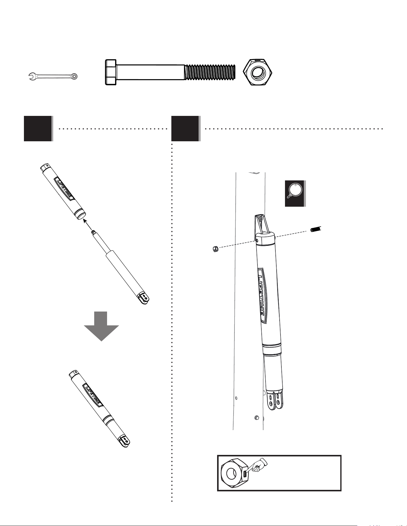
SECTION 5 (CONTINUED)
TOOLS AND HARDWARE REQUIRED
5.1
ACX (x1)
BSG (x1)
(x2)
1/2” (13 mm)
AKG
AKF
BSG
ACX
ALL
5.2
• Slide the Gas Spring Cover (AKG) onto
the Gas Spring (AKF) as shown.
• Align the holes in the Gas Spring Cover (AKG) and the Gas Spring (AKF)
with the holes in the Pole Bracket (ALL), and attach the Gas Spring
assembly to the Pole Bracket with the hardware shown.
• Tighten the Centerlock Nut
(BSG) until it is fl ush with
the end of the Bolt.
• A Centerlock Nut
will require some effort
to thread onto a Bolt.
See page 2 for details.
27
SECTION 5 (CONTINUED)
TOOLS AND HARDWARE REQUIRED
5.3
5.4
9/16” (≈14 mm)
ABA (x1)
ABB (x1)
6 1/2 in/po (≈17cm)
ABA
ABB
AMN
AKI
AQE
AKF
• Position the Trigger (AMN) inside of the Handle (AKI) as shown, and secure the Trigger to the Handle with the
hardware shown.
• Insert the Release Pin (AQE) through the Gas Spring (AKF).
• Tighten the Centerlock Nut (ABB) until
it is fl ush with the end of the Bolt.
(x2)
28
SECTION 5 (CONTINUED)
TOOLS AND HARDWARE REQUIRED
5.5
3/4” (≈19 mm)
AAX (x1)
AKI
AMN
AQE
9/16” (≈14 mm)
ABA (x1)
ABB (x1)ABM (x2)
6 1/2 in/po (≈17cm)
ABA
ABB
ABM
ABM
AKI
ALF
• Slide the Handle (AKI) under the Gas Spring (AKF) so that the Release Pin (ALV) rests in the channels of the Trigger (AMN). Position
the Rear Lifter Arms (ALS) between the Handle and Trigger, and secure with the hardware shown.
5.6
• Secure the Handle (AKI) to the Middle Pole (ALF) with the hardware shown. Make sure to place the Spacers (ABM) between
the Handle Assembly and the Middle Pole as shown.
• Tighten the Centerlock Nut
(ABB) until it is fl ush with
the end of the Bolt.
• Tighten the Centerlock Nut (AAX) until
it is fl ush with the end of the Bolt.
AAW
AAX
ALS
ALS
(x2)
(x2)
6 1/2 in/po (≈17cm)
AAW (x1)
29
SECTION 5 (CONTINUED)
TOOLS AND HARDWARE REQUIRED
AAX (x1)
AAD (x1)
3/4” (≈19 mm)
7 1/16 in/po (≈18cm)
AKH
AQE
5.7
5.8
• Apply grease from the Grease Packet (AKH) on to the Release Pin (ALV).
• Connect the Rear Lifter Arms (ALS) to the inside of the Lower Extension Arms (BGP) with the hardware shown. Place a
Spacer (APR) between the Rear Lifter Arms as shown.
• Tighten the Centerlock Nut (AAX) until
it is fl ush with the end of the Bolt.
APR (x1)
AAD
APR
BGP
ALS
ALS
BGP
AOR
AOR
AAX
AKH (x1)
(x2)
30
Plastic Parts
TOOLS REQUIRED
PARTS REQUIRED
HARDWARE REQUIRED
FINAL ASSEMBLY
6
AKZ (x1)
(x1)(x1) (x1)
325 lb (147kg)
ADP (x10)
BCU
Hardware Bag
AKP (x1)
1109 02 5
10’
9’6”
9’
8’6”
7’6”
8’
BAA (x2)
FIQ (x1)
FIR (x1)
AJQ (x1)
BAB (x1)
(x1)
AEF (x2)
(x1)
31
TOOLS AND HARDWARE REQUIRED
SECTION 6 (CONTINUED)
6.1
ADP (x10)
• Remove the plastic fi lm from the Backboard (AJI), and attach the Center Frame Pad (AJQ) to the Backboard in the location
shown with the hardware indicated. Make sure that the Center Frame Pad is oriented and centered on the metal piece of the
Backboard.
6.2
• Attach the Corner Frame Pads (BAA and BAB) to the Backboard in the locations indicated with the hardware indicated.
(x1)
AJI
BAA
BAB
AJQ
ADP
ADP
ADP
ADP
ADP
ADP
ADP
ADP
ADP
ADP
• The Corner Frame Pads (BAA and BAB) will
overlap the Center Frame Pad (AJQ).
(x1)
32
TOOLS AND HARDWARE REQUIRED
SECTION 6 (CONTINUED)
WARNING
For safety reasons, we recommend that sand be used
instead of water to fill the Base. If a leak develops, water
could run out unnoticed, allowing the system to fall over,
resulting in serious personal injuries, or property damage.
If using Water, check the Base carefully for leaks. If a
leak is found, lay the system down on the ground and
call Customer Service. Do not use, stand up, or play on
a leaking system.
6.3a
325 lb (≈147kg)
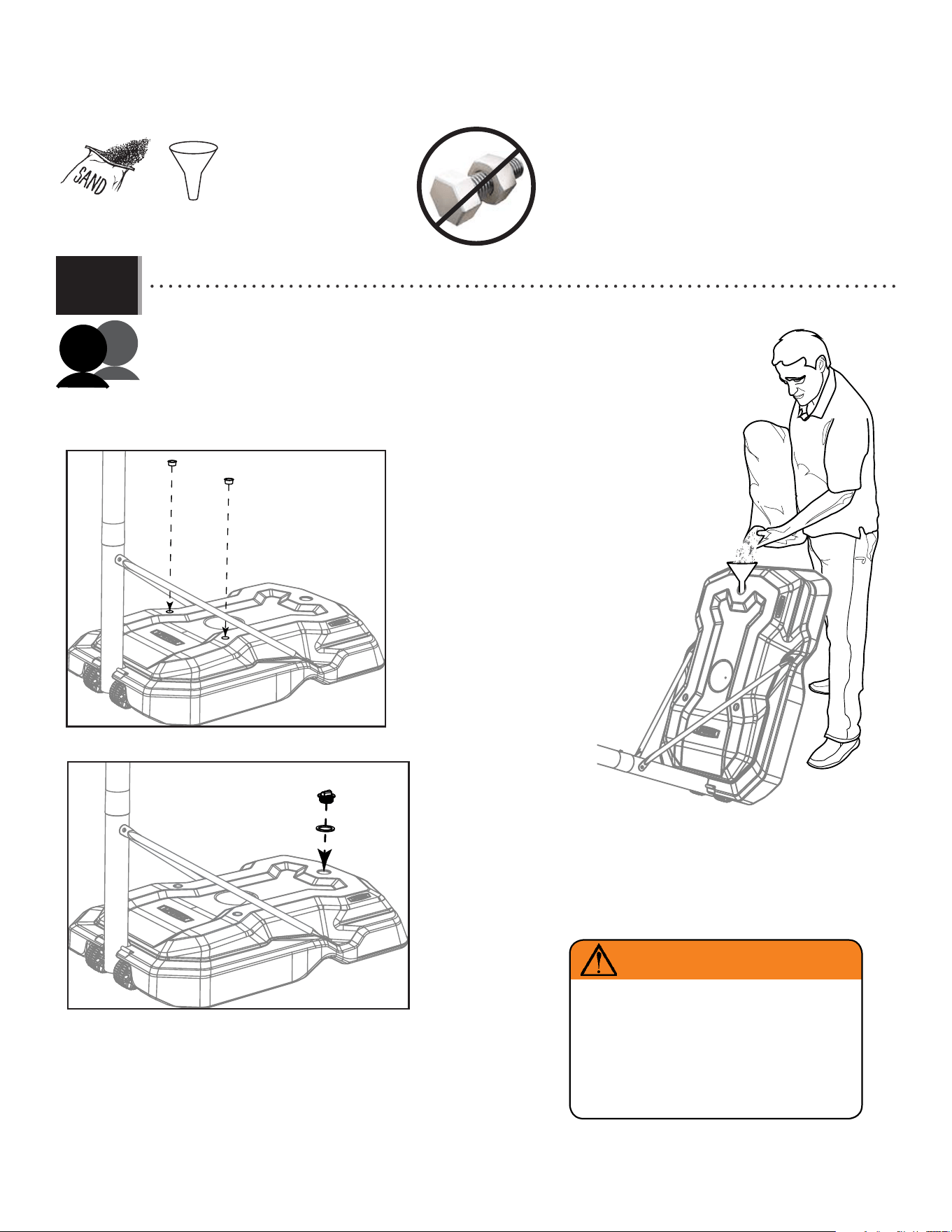
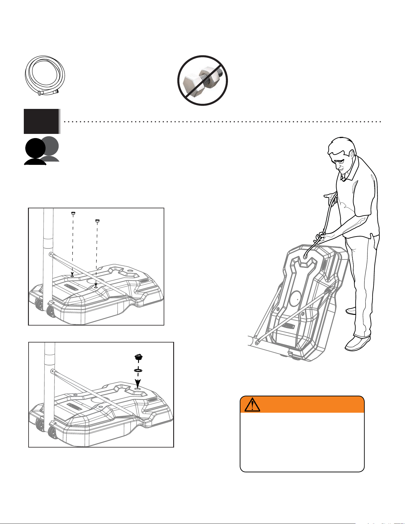
• To prevent serious injuries, the pole should be held down by one adult at all times while the other fi lls the base.
Option a: fi lling the base with sand:
(325 lb (≈147 kg) of sand required)
1. Insert a plug (AEF) into each of the two holes in the base (Fig. 1).
2. Using a funnel, fi ll the base with sand (Fig. 2).
3. Using two adults, stand the base up on a smooth surface and continue fi lling until you
have, at least, 325 lb (≈147kg) of sand in the base.
4. Place the gasket (FIR) onto the cap (FIQ) and screw the cap onto the base until tight (Fig. 3).
(x1)
AEF
AEF
FIQ
FIR
Fig. 1
Fig. 3
Fig. 2
Sand
Sable
Arena
33
TOOLS AND HARDWARE REQUIRED
SECTION 6 (CONTINUED)
AJM
Option b: fi lling the base with water:
1. Insert a plug (AEF) into each of the two holes in the base (Fig. 1).
2. Using a hose, fi ll the base with cold water up to the fi ll hole, leaving two inches of
space at the top for expansion (Fig. 2).
3. Add one tablespoon of chlorine bleach to the water to prevent algae
formation.
4. Using two adults, stand the base up on a smooth surface.
5. Place the gasket (FIR) onto the cap (FIQ) and screw the cap onto the base
until tight (Fig. 3).
6. Check for leaks.
(x1)
6.3b
Fig. 2
• To prevent serious injuries, the pole should be held down by one adult at all times while the other fi lls the base.
AEF
AEF
FIQ
FIR
Fig. 1
Fig. 3
WARNING
For safety reasons, we recommend that sand be used
instead of water to fill the Base. If a leak develops, water
could run out unnoticed, allowing the system to fall over,
resulting in serious personal injuries, or property damage.
If using Water, check the Base carefully for leaks. If a
leak is found, lay the system down on the ground and
call Customer Service. Do not use, stand up, or play on
a leaking system.
34
TOOLS AND HARDWARE REQUIRED
SECTION 6 (CONTINUED)
6.4
6.5
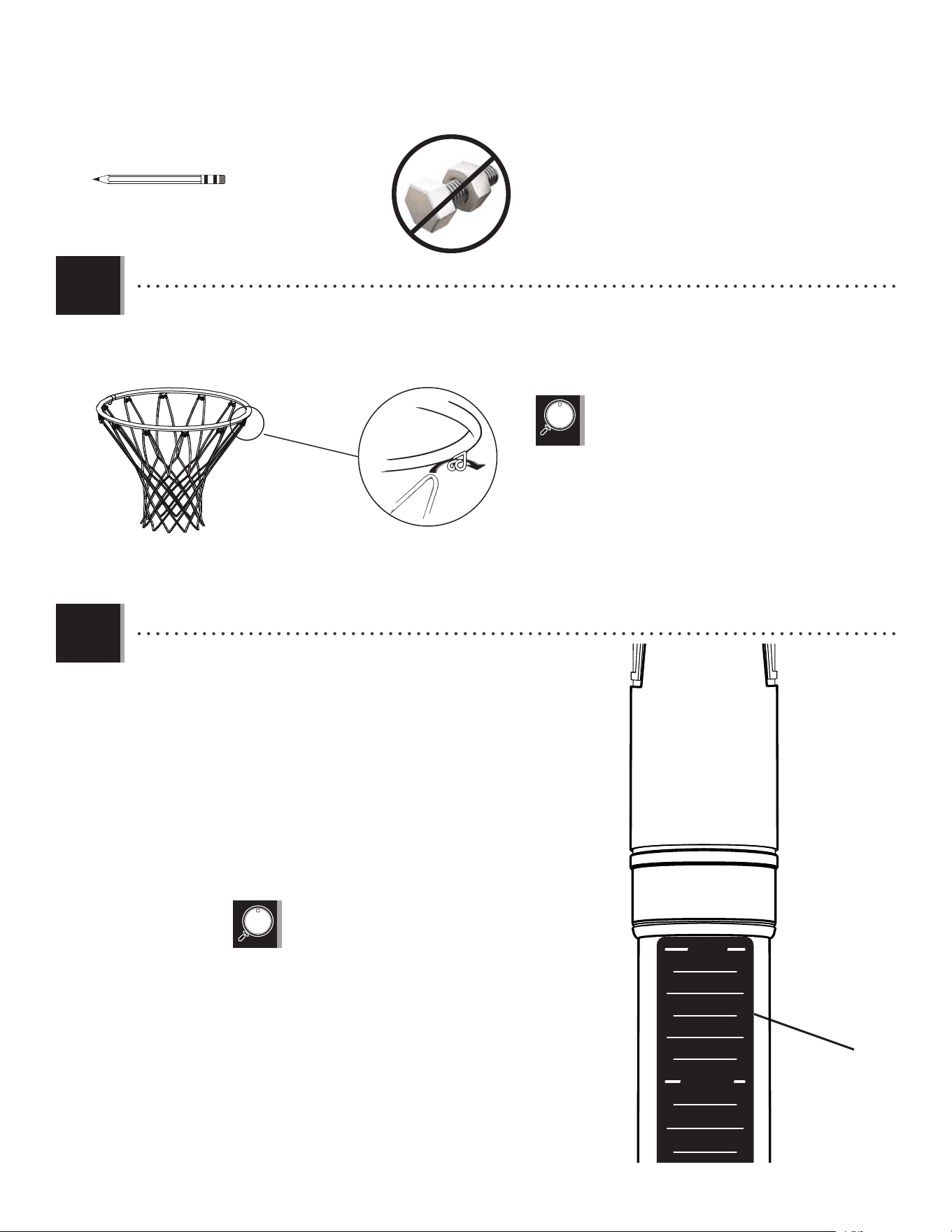
• Attach the Net (ALX).
• Actual Height Sticker (AKP) and Gas
Spring Cover (AKG) may vary from
those shown here.
(x1)
AKZ
ALX
• If a replacement Net is needed, please call our Customer
Service Department. Our Nets are shorter than average to
reduce the risk of entanglement.
• Raise the Backboard until the top of the Rim measures 10 feet from
the playing surface. Apply the Height Adjustment Sticker (AKP) onto the
Gas Spring (GFL), lining up the edge of the Gas Spring Cover with the 10-
foot mark on the sticker. Press the sticker into place while carefully
removing the rest of the backing.
AKP
12024 57
10'
9.5'
9'
8.5'
7.5'
8'
AKF
AKG

35
The life of your basketball system depends on many variables. The climate, exposure to corrosives such as salt, pesticides, or herbicides,
and excessive use or misuse can all contribute to Pole failure, which may cause property damage or personal injury.
Check your basketball system frequently for loose hardware, excessive wear, and signs of corrosion. For safety reasons, and to
prolong the life of your basketball system, you must take the following preventive measures.
a. Check all nuts and bolts. If any are loose, tighten them.
b. Check all parts for excessive wear and tear. If necessary, replace any parts that have been worn or damaged through usage.
Contact our customer service department for replacement parts.
c. Inspect the warning sticker on the pole. If it is ripped, faded, or illegible, call our customer service department to request a
replacement sticker.
d. Check all pole sections for visible rust or chipped or cracked paint. If either are present, do the following:
1. Use an emery cloth to completely remove any rust or chipped paint.
2. Clean the area with a damp cloth and allow it to dry.
3. Apply two coats of a rust preventative, high gloss enamel paint to the area. Allow the paint to dry between coats.
IF RUST HAS PENETRATED THROUGH THE POLE ANYWHERE, REPLACE IT IMMEDIATELY!
MAINTENANCE INSTRUCTIONS
LIFETIME’S PROMISE TO YOU:
We invite you to read our privacy policy at www.lifetime.com
REGISTER today!
At Lifetime
®
, we are committed to providing innovative and quality products. While registering, you will have the opportunity to give us your feedback. Your input is
valuable to us.
• You can also opt in to receive new product notifi cations or promotions.
• In the unlikely event of a product recall or safety modifi cation, your registration provides the information we need to notify you directly.
• Registration is fast, easy, and completely voluntary.
Maintaining your privacy is our long-standing policy at Lifetime
®
. And you can rest assured that Lifetime
®
will not sell or provide your personal data to other third parties,
or allow them to use your personal data for their own purposes.
LA PROMESA DE LIFETIME
®
PARA USTED:
Lo invitamos a leer nuestra política de privacidad en www.lifetime.com (sólo en inglés)
¡REGISTRARSE hoy mismo!
En Lifetime
®
, estamos comprometidos a ofrecer productos innovadores y de calidad. Al registrarse, usted tendrá la oportunidad de darnos su retroalimentación. Su
información es valiosa para nosotros.
• También puede optar por recibir nuestras notifi caciones o promociones.
• En el caso improbable de que el producto deba ser retirado del mercado o que sufra alguna modifi cación, su registro provee la
información que necesitamos para notifi carle directamente.
• El registro es rápido, fácil y completamente voluntario.
Mantener privacidad es nuestra política permanente en Lifetime
®
. Y puede estar seguro que Lifetime
®
no venderá ni dará datos personales a terceros, ni les permitirá usar
datos personales para sus propios fi nes.
LA PROMESSE DE LIFETIME :
Nous vous invitons à lire notre politique de confi dentialité à www.lifetime.com (en anglais seulement)
ENREGISTRER CE PRODUIT aujourd’hui!
Chez Lifetime
®
, nous nous engageons à fournir des produits innovateurs de qualité. Lors de votre inscription, vous aurez l’occasion de nous faire parvenir vos com-
mentaires. Votre opinion est importante pour nous.
• On peut également choisir de recevoir des avis ou des promotions dans le cadre de nouveaux produits.
• Dans l’éventualité peu probable d’un rappel ou d’un avis de sécurité, l’inscription fournit les renseignements nécessaires nous
permettant de communiquer avec vous.
• L’inscription est rapide, facile et complètement volontaire.
Conserver votre confi dentialité est notre politique de longue date chez Lifetime
®
. Vous pouvez donc être rassuré par le fait que Lifetime
®
ne vendra pas ou ne fournira
pas vos données personnelles à des tiers, et ne leur permettra pas d’utiliser vos données personnelles à leurs propres fi ns.
REGISTER YOUR PRODUCT ONLINE AT WWW.LIFETIME.COM
REGISTRAR EL PRODUCTO EN LÍNEA EN WWW.LIFETIME.COM
ENREGISTRER CE PRODUIT EN LIGNE À WWW.LIFETIME.COM

36
NOTES

37
NOTES
38
WARNING STICKER / AUTOCOLLANT D’AVERTISSEMENT / ETIQUETA DE ADVERTENCIA
FAUTE DE NE PAS SUIVRE CES AVERTISSEMENTS, VOUS RISQUEZ DE CAUSER
DES BLESSURES GRAVES ET/OU DES DOMMAGES À L’ÉQUIPEMENT.
Le propriétaire doit s’assurer que tous les joueurs
connaissent et appliquent les règles suivantes afin d’utiliser
l’équipement en toute sécurité.
SI NO SE OBEDECEN ESTAS ADVERTENCIAS PUEDEN PRODUCIRSE
GRAVES LESIONES Y/O DAÑOS A LA PROPIEDAD.
El propietario del sistema debe asegurarse de que todos
los jugadores conozcan y respeten estas reglas para que el
sistema se use en forma segura.
FAILURE TO FOLLOW THESE WARNINGS MAY RESULT IN SERIOUS INJURY
AND/OR PROPERTY DAMAGE.
Owners must ensure that all players know and follow these
rules for safe operation of the system.
• Only hang from the rim briefly to regain balance or avoid injuring
others. Release the rim as soon as safely possible.
• During play, especially when performing dunk type activities, keep
player’s face away from the backboard, rim, and net. Serious injury
could occur if teeth/face come in contact with the backboard, rim, or
Net. Player should wear a mouth guard during play.
• Do not slide, climb, or play on base or pole.
• Completely fill base according to manufacturer’s instructions. Never
leave the unit standing in an upright position without first filling the base
with weight or the system will tip quickly causing serious personal injury.
• When adjusting height or moving system, keep hands and fingers
away from moving parts.
• Do not allow children to move or adjust system.
• Do not wear jewelry (rings, watches, necklaces, etc.) during play.
Objects may entangle in net.
• Keep water and organic material away from pole base. Grass, litter,
etc. could cause corrosion and/or deterioration.
• Never play on damaged equipment.
• Surface beneath the base must be smooth and free of gravel or other
objects. Punctures cause leakage and could cause system to tip over.
• Once a month check pole and all metal parts for signs of
corrosion (rust, pitting, chipping). Completely remove rust and
repaint with exterior enamel. If rust has penetrated any steel part,
replace that part immediately.
• Check system before each use for proper ballast, loose hardware,
excessive wear, instability, and signs of corrosion and repair before use.
• Do not use system during windy or severe weather. System may
tip over. Place system in an area protected from the wind or in an
area away from property that may be damaged if the system falls,
and from overhead power lines.
• Do not use the system to lift or hoist anything. The mechanism is
designed to lift only the weight of the backboard and rim. Do not
hang anything from the handle, rim, backboard, or lifter arms as
this will damage the system and void the warranty.
• Ne pas se suspendre à l’anneau plus que nécessaire pour
retrouver l'équilibre ou éviter de blesser les autres joueurs.
Relâcher l’anneau aussitôt que possible.
• Lors d’un match, particulièrement dans le cas des smashs, le
visage du joueur ne doit pas faire face au panneau, à l’anneau, ni au
filet. Le joueur risque de graves blessures si ses dents ou son visage
entrent en contact avec le panneau, l’anneau, ou le filet. Les joueurs
doivent toujours porter un protège-dents lorsqu’ils jouent.
• Ne pas glisser, ne pas grimper, et ne pas jouer sur la base ou le
poteau.
• Remplir complètement la base selon les instructions du fabricant.
Ne jamais laisser l’unité debout de plein pied sans avoir d’abord rempli
la base avec un poids ou l’équipement pourrait basculer rapidement
et causer de graves blessures.
• Lors du réglage de la hauteur ou lors du déplacement
de l’équipement, garder les mains et doigts loin des pièces mobiles.
• Ne pas permettre aux enfants de déplacer ou d’ajuster l’équipement.
• Ne pas porter de bijoux (bagues, montres, colliers, etc.) pendant le
jeu. Ces objets pourraient s’accrocher au filet.
• La surface sur laquelle est posée la base doit être lisse et sans
gravier ou tout autre objet qui pourrait trouer la base entraînant ainsi
une fuite ce qui pourrait faire basculer l’équipement.
• Garder de l’eau et de la matiére organique loin de la base. Le
gazon, les déchets, etc. pourraient provoquer la corrosion et/ou la
détérioration.
• Une fois par mois, vérifier que le poteau et toutes les pièces en métal
ne montrent pas de signes de corrosion (rouille, piqûres, écaillage).
Enlever toute la rouille et repeindre complètement avec une peinture
pour extérieur. Si la rouille a pénétré une des pièces en acier, il
faut la remplacer immédiatement la pièce en question.
• Chaque fois avant d'utiliser le système, vérifier d’abord l’équilibre,
la possibilité de pièces desserrées ou usées, la stabilité de
l’équipement et tout signe de corrosion ou réparation nécessaire avant
utilisation.
• Ne jamais jouer avec un équipement endommagé.
• Ne pas utiliser l’équipement lors de fortes rafales de vent ou
de mauvais temps. L’équipement pourrait basculer. Placer
l’équipement dans un endroit abrité du vent ou loin des structures
qu’il pourrait endommager s’il basculait, et loin des fils électriques.
• Ne pas utiliser l’équipement pour lever ou soulever quoique ce
soit. Son mécanisme a été conçu uniquement pour soutenir le
poids du panneau et de l’anneau. Ne rien accrocher au manche,
à l’anneau, au panneau ni aux leviers sous peine d’endommager
l’équipement et d’annuler la garantie.
•Colgarse del aro sólo en forma breve, para recuperar el equilibrio
o evitar lesionar a otros jugadores. Soltarse del aro lo más pronto que
pueda hacerlo con seguridad.
• Durante el juego, especialmente al embocar violentamente de alto,
la cara de los jugadores debe mantenerse alejada del tablero, el aro
y la red. Pueden producirse lesiones graves si los dientes o la cara
entran en contacto con el tablero, el aro o la red. Los jugadores deben
usar un protector bucal durante el juego.
• No deslizarse, no trepar ni jugar sobre la base o el poste.
• Llenar la base completamente siguiendo las instrucciones del
fabricante. Nunca dejar la unidad en posición de uso sin haber
llenado previamente la base con material de contrapeso, pues el
sistema podría tumbarse rápidamente y causar graves lesiones
personales.
• Mantener las manos y los dedos alejados de las piezas movibles
al regular la altura o al desplazar el sistema.
• No dejar que los niños regulen ni desplacen el sistema.
• No usar joyas (anillos, relojes, collares o gargantillas, etc.) durante
el juego. Estos objetos pueden engancharse en la red.
• La superficie donde se coloque la base debe estar lisa y desprovista
de piedras, grava u otros objetos. Las perforaciones pueden originar
pérdidas, y éstas pueden hacer que el sistema se tumbe.
• Guardar aqua y materia orgánica. Césped, basura, etc.,
prodrian causar corrosión et/o deterioros.
• Controlar el poste y todas las piezas metálicas una vez al mes
en busca de signos visibles de corrosión (oxidación, picaduras,
escamado). Eliminar todo rastro de óxido y volver a pintar con esmalte
para exteriores. Si el óxido ha penetrado cualquier pieza de acero,
reemplazar esa pieza de inmediato.
• Inspeccionar el sistema antes de cada uso para verificar que esté
adecuadamente contrapesado, que los elementos de fijación no
estén flojos, que no haya desgaste excesivo, inestabilidad ni signos
de corrosión. Al encontrar irregularidades, repararlas antes de usar
el sistema. Nunca jugar con un equipo dañado.
• No usar el sistema en presencia de vientos fuertes o condiciones
climáticas adversas, ya que puede tumbarse. Colocar la unidad en
una posición de almacenamiento y/o en una zona a resguardo
del viento, lejos de propiedades personales que puedan dañarse
si el sistema se cae, y de líneas de suministro de energía.
• No usar el sistema para levantar ningún objeto. El mecanismo está
diseñado para elevar solamente el peso del tablero con el aro. No
colgar nada de la agarradera, el aro, el tablero ni los brazos de
elevación, ya que esto puede dañar el sistema y anular la garantía.
www.lifetime.com
# 1180194
11/23/2015
Lifetime Products, Inc., Clearfield, UT 84016
1-800-225-3865
WARNING
ADVERTENCIAAVERTISSEMENT

39
THE MANUFACTURER RESERVES THE RIGHT TO MAKE SUBSTITUTIONS TO WARRANTY CLAIMS IF PARTS ARE UNAVAILABLE OR OBSOLETE.
1. Lifetime basketball systems are warranted to the original purchaser to be free from defects in material or workmanship for a
period of fi ve years (60 months) from the date of original retail purchase. The word “defects” is defi ned as imperfections that
impair the use of the product. Defects resulting from misuse, abuse or negligence will void this warranty. This warranty does not
cover defects due to improper installation, alteration or accident. This warranty does not cover damage caused by vandalism,
rusting, “acts of nature” or any other event beyond the control of the manufacturer.
2. This warranty is nontransferable and is expressly limited to the repair or replacement of defective product. If the product is
defective within the terms of this warranty, Lifetime Products, Inc. will repair or replace defective parts at no cost to the purchaser.
Shipping charges to and from the factory or distribution center are not covered and are the responsibility of the purchaser. Labor
charges and related expenses for removal, installation or replacement of the product or its components are not covered under
this warranty.
3. This warranty does not cover scratching or scu ng of the product that may result from normal usage. In addition, defects
resulting from intentional damage, negligence, unreasonable use or hanging from the rim will void this warranty.
4. Liability for incidental or consequential damages is excluded to the extent permitted by law. While every attempt is made to
embody the highest degree of safety in all equipment, freedom from injury cannot be guaranteed. The user assumes all risk of
injury resulting from the use of this product. All merchandise is sold on this condition, and no representative of the company
may waive or change this policy.
5. This product is not intended for institutional or commercial use; Lifetime Products, Inc. does not assume any liability for such use.
Institutional or commercial use will void the warranty.
6. Our goods come with guarantees that cannot be excluded under the Australian Consumer Law. You are entitled to a replacement
or refund for a major failure and for compensation for any other reasonably foreseeable loss or damage. You are also entitled to
have the goods repaired or replaced if the goods fail to be of acceptable quality and the failure does not amount to a major failure.
7. This warranty is expressly in lieu of all other warranties, expressed or implied, including warranties of merchantability or fi tness
for use to extent permitted by Federal and state law. Neither Lifetime Products, Inc., nor any representative assumes any other
liability in connection with this product. This warranty gives you specifi c legal rights, and you may also have other rights which
vary from state to state.
www.lifetime.com
PLEASE INCLUDE YOUR DATED SALES RECEIPT AND PHOTOGRAPHS OF DAMAGED PARTS.
REPORT PRODUCT DEFECTS IN WRITING TO:
Lifetime Products, Inc., PO Box 160010 Clearfi eld, UT 84016-0010 or dial 1-800-225-3865.
REGISTER YOUR PRODUCT FOR QUICKER CUSTOMER SERVICE.
Visit www.lifetime.com or dial 1-800-225-3865 to register your product today.
FOR INTERNATIONAL WARRANTY CLAIMS:
All warranty claims must be accompanied by a sales receipt. Report all warranty claims in writing to your regional sales
support representative. Please include your dated sales receipt and photographs of damaged parts.
To Identify the representative for your region, please visit: www.lifetime.com/international
5-YEAR LIMITED FACTORY WARRANTY
W
A
R
R
A
N
T
Y
W
A
R
R
A
N
T
Y
WARRANTY
40
www.lifetime.com
or dial 1-800-424-3865
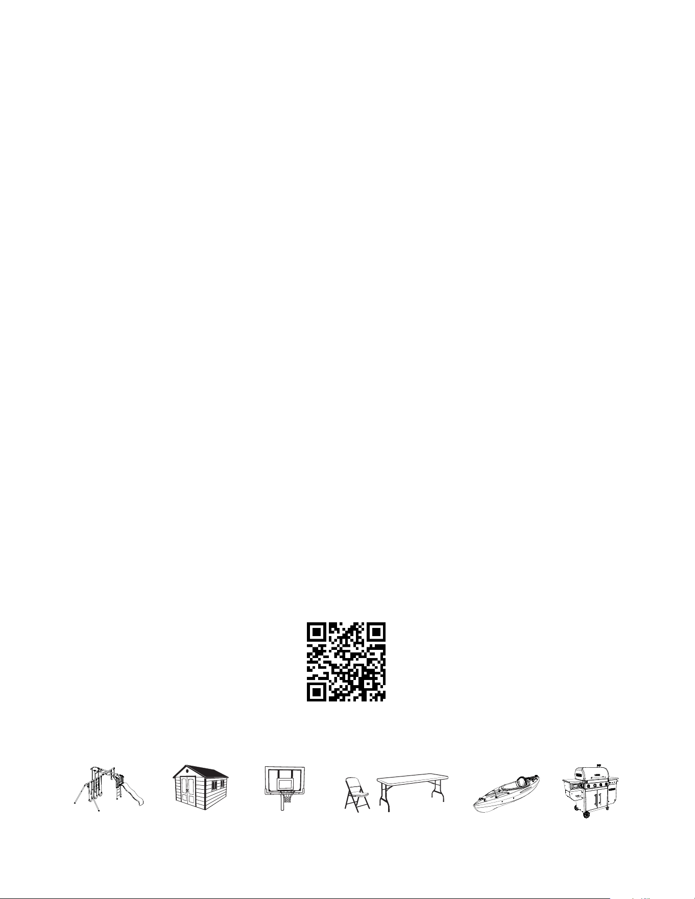
To purchase accessories or other Lifetime
®
products, visit us at:
www.lifetime.com
ENHANCE YOUR LIFETIME
®
PURCHASE BY ADDING ACCESSORIES OR OTHER GREAT PRODUCTS
© 2023
Lifetime Products, Inc., Clearfi eld, UT
1234496
1/12/2023