perator s
P R 0 F E S S I 0 N A
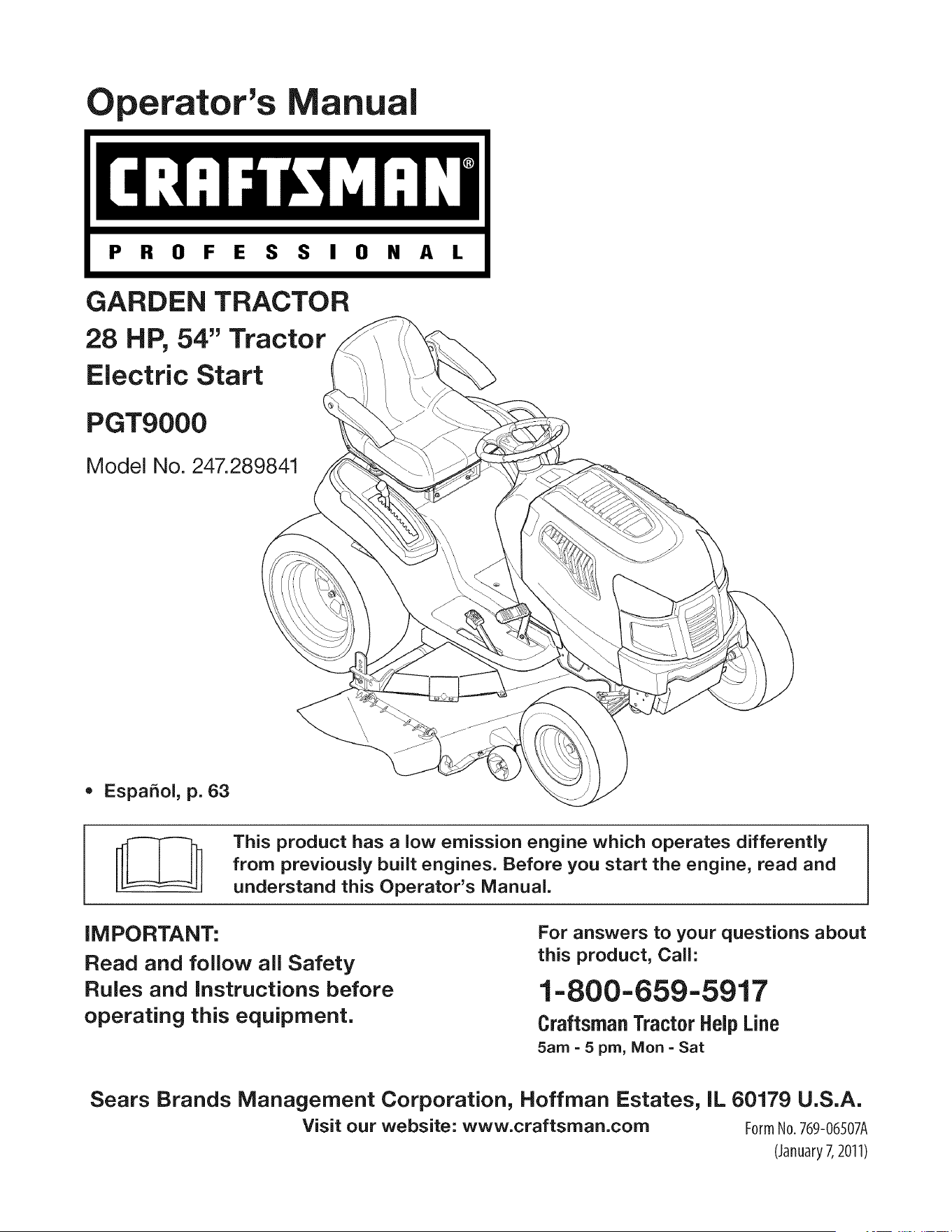
GARDEN TRACTOR
28 HP, 54" Tractor
Electric Start
PGT9000
Model No. 247.289841
= EspaSol, p. 63
This product has a low emission engine which operates differently
from previously built engines. Before you start the engine, read and
understand this Operator's Manual.
iMPORTANT:
Read and foJlow aJJSafety
RuJes and instructions before
operating this equipment.
For answers to your questions about
this product, Call:
1=800=659=5917
Craftsman Tractor Help Line
5am = 5 pro, Mort =Sat
Sears Brands Management Corporation, Hoffman Estates, IL 60179 U.S.A.
Visit our website: www.craftsman.com FormNo.769-%507A
(January7,2011)
Warranty Statement .......................................................... 2
Safety Instructions ............................................................ 3
Slope Guide ....................................................................... 8
Safety Labels .................................................................... 9
Assembly ......................................................................... 10
Know your Lawn Mower .................................................. 13
Operation ........................................................................ 16
Service and Maintenance .............................................. 19
Off-Season Storage ........................................................ 30
Troubleshooting .............................................................. 31
Parts List ......................................................................... 34
Espa_oi ............................................................................ 63
Service Numbers ............................................. Back Cover
CRAFTSMAN PROFESSIONAL FULL WARRANTY
FORTWOYEARSfromthe dateof purchase,all non-expendablepartsof this ridingequipmentarewarrantedagainstanydefects in materialor
workmanship.A defectivenon-expendablepartwill receivefreein-homerepairor replacementif repairis impossible.
FORFiVEYEARSfrom the dateof purchase,theframe and frontaxle of this ridingequipmentare warrantedagainstanydefectsinmaterialor
workmanship.A defectiveframe or front axle will receivefree in-homerepairor replacementif repairis impossible.
All of the abovewarrantycoverageappliesforonly oneyearfromthe dateof purchaseif thisridingequipmentis everusedwhileproviding
commercialservicesor if rentedto anotherperson.
FOR90 DAYSfromthedate of purchase,the battery(anexpendablepart) of this ridingequipmentis warrantedagainstanydefectsin materialor
workmanship(ourtestingprovesthat it will not holdacharge).A defectivebatterywill receivefree in-homereplacement.
ADDITIONALLIFETIMELIMITEDWARRANTYon CASTIRON FRONTAXLE(if equipped)
FORASLONGAS iT iSUSEDby the originalownerafterthe fifth yearfrom thedate of purchase,
the cast ironfrontaxle (if equipped)of thisridingequipmentis warrantedagainstany defectsin material
or workmanship.Withproofof purchase,a defectivecast front axlewill receivefree in-homereplacement.
WARRANTYSERVICE
Forwarrantycoveragedetailsto obtainfree repairor replacement,call 1-800-659-5917or visitthe web site:www. craftsman.corn
Inall casesabove,if part repairor replacementis impossible,the ridingequipmentwill be replacedfreeof chargewiththe sameor an equivalent
model.
ThiswarrantycoversONLYdefects in materialand workmanship.Warrantycoveragedoes NOT include:
• Expendableparts(exceptfor battery)that can wearoutfromnormalusewithin the warrantyperiod,includingbut not limitedto blades,
sparkplugs,air cleaners,belts,andoil filters.
• Standardmaintenanceservicing,oil changes,ortune-ups.
• Tire replacementor repaircausedby puncturesfromoutsideobjects,suchas nails,thorns,stumps,or glass.
• Tire or wheel replacementor repairresultingfrom normalwear,accident,or improperoperationor maintenance.
• Repairsnecessarybecauseof operatorabuse,includingbut not limitedto damagecausedbytowing objectsbeyondthe capabilityof
the riding equipment,impactingobjectsthat bend the frame,axle assemblyor crankshaft,or over-speedingthe engine.
• Repairsnecessarybecauseof operatornegligence,includingbut notlimitedto, electricalandmechanicaldamagecausedby improper
storage,failureto use the propergradeandamountof engineoil, failureto keepthedeckclearof flammabledebris,or failureto
maintainthe ridingequipmentaccordingto the instructionscontainedin theoperator'smanual.
• Engine(fuel system)cleaningor repairscausedby fueldeterminedto be contaminatedor oxidized(stale). Ingeneral,fuelshouldbe
usedwithin 30 days of its purchasedate.
• Normaldeteriorationandwear of theexteriorfinishes,or productlabel replacement.
Thiswarrantygivesyouspecificlegal rights,and you mayalso haveother rightswhichvaryfromstateto state.
Sears Brands ManagementCor
EngineOil: SAE30
Fuel: UnleadedGasoline
SparkPlug: Champion@RC12YC
Engine: Briggs& StrattonProfessionalSeries
_oration,Hoffman Estates, IL 60179
Model Number
Serial Number
Dateof Purchase
Recordthe modelnumber,serialnumber,
anddateof purchaseabove.
© KCD IP,LLC 2
Thissymbolpointsout importantsafetyinstructionswhich,if not
followed,couldendangerthepersonalsafetyand/orpropertyof
yourselfandothers. Readand followall instructionsin this manual
beforeattemptingto operatethis machine.Failureto complywith
theseinstructionsmayresultin personalinjury.Whenyou seethis
symbol,HEEDITSWARNING!
CALIFORNIA PROPOSITION 65
EngineExhaust,someof itsconstituents,andcertainvehicle
componentscontainoremitchemicalsknownto Stateof California
to cause cancerand birthdefectsorother reproductiveharm.
Batteryposts,terminals,and relatedaccessoriescontainleadand
leadcompounds,chemicalsknownto the Stateof Californiato
causecancerandreproductiveharm.Washhandsafter handling.
Thismachinewasbuiltto beoperatedaccordingto the safeopera-
tion practicesin this manual.As withanytype of powerequipment,
carelessnessorerroron the partof the operatorcan resultin serious
injury.Thismachineis capableof amputatingfingers,hands,toes
andfeetandthrowingdebris.Failureto observethe followingsafety
instructionscouldresultin seriousinjuryor death.
Your Responsibility--Restrictthe use of this powermachineto
personswho read,understandandfollowthewarningsand instruc-
tionsin thismanualandon the machine.
SAVE THESE INSTRUCTIONS!
GENERAL OPERATION
• Read,understand,andfollowall instructionson the machineand
in themanual(s)beforeattemptingto assembleandoperate.
Keepthis manualina safeplacefor futureand regularreference
andfor orderingreplacementparts.
• Befamiliarwithall controlsandtheir properoperation.Knowhow
to stop the machineanddisengagethemquickly.
• Neverallowchildrenunder 14yearsoldto operatethis machine.
Children14yearsoldandover shouldreadandunderstandthe
operationinstructionsandsafetyrulesin this manualandshould
betrainedand supervisedbya parent.
• Neverallowadultsto operatethis machinewithoutproper
instruction.
• Tohelp avoidbladecontactor a thrownobjectinjury,keep
bystanders,helpers,childrenand pets at least75feetfromthe
machinewhile it is in operation.Stopmachineif anyoneenters
the area.
• Thoroughlyinspectthe areawherethe equipmentis to be used.
Removeallstones,sticks,wire,bones,toys,andotherforeign
objectswhichcouldbe pickedup and thrownby the blade(s).
Thrownobjectscan causeseriouspersonalinjury.
• Planyour mowingpatternto avoiddischargeof materialtoward
roads,sidewalks,bystandersandthe like.Also, avoiddischarg-
ingmaterialagainstawall or obstructionwhich maycause
dischargedmaterialto ricochetbacktowardthe operator.
• Alwayswear safetyglassesor safetygogglesduring operation
andwhile performingan adjustmentor repairto protectyoureyes.
Thrownobjectswhich ricochetcancauseseriousinjuryto the
eyes.
• Wearsturdy,rough-soledwork shoesand close-fittingslacksand
shirts.Loosefittingclothesandjewelrycanbe caughtin movable
parts.Neveroperatethismachineinbarefeetorsandals.
• Be awareof the mowerand attachmentdischargedirectionand
do not pointit at anyone.Donot operatethe mowerwithoutthe
dischargecoverorentiregrass catcherin its properplace.
Donot put handsor feet near rotatingpartsor underthe cutting
deck. Contactwith the blade(s)can amputatehandsandfeet.
A missingor damageddischargecovercan causeblade contact
or thrownobjectinjuries.
• Stoptheblade(s)whencrossinggraveldrives,walks,or roads
andwhile notcuttinggrass.
• Watchfor trafficwhenoperatingnearorcrossingroadways.This
machineis not intendedfor useon any public roadway.
• Donot operatethe machinewhile underthe influenceof alcohol
or drugs.
• Mowonly indaylightorgoodartificiallight.
Nevercarrypassengers.
• Disengageblade(s)beforeshiftinginto reverse.Backup slowly.
Alwayslookdownand behindbeforeand while backingto avoida
back-overaccident.
3
• Slowdownbeforeturning.Operatethe machinesmoothly.Avoid
erraticoperationandexcessivespeed.
Disengageblade(s),setparkingbrake,stopengineandwaituntil
the blade(s)come to a completestopbeforeremovinggrass
catcher,emptyinggrass,uncloggingchute,removinganygrassor
debris,or makinganyadjustments.
Neverleavea runningmachineunattended.Alwaysturnoff
blade(s),setparkingbrake,stopengineandremovekeybefore
dismounting.
Useextracare whenloadingorunloadingthe machineintoa
traileror truck. This machineshouldnot bedrivenup or down
ramp(s),becausethe machinecouldtip over,causingserious
personalinjury.The machinemustbe pushedmanuallyon
ramp(s)to loador unloadproperly.
Mufflerandenginebecomehotandcan causea burn.Do not
touch.
Checkoverheadclearancescarefullybeforedrivingunderlow
hangingtree branches,wires,door openingsetc., wherethe
operatormaybestruckor pulledfromthe machine,which could
resultinseriousinjury.
Disengageallattachmentclutchesanddepressthe brakepedal
completelybeforeattemptingto start engine.
Yourmachineisdesignedto cut normalresidentialgrassof a
heightno morethan 10".Do not attemptto mowthroughunusually
tall,dry grass (e.g.,pasture)or piles of dry leaves.Drygrassor
leavesmaycontactthe engineexhaustand/or builduponthe
mowerdeckpresentinga potentialfire hazard.
Useonlyaccessoriesand attachmentsapprovedfor this machine
by the machinemanufacturer.Read,understandandfollowall
instructionsprovidedwiththe approvedaccessoryor attachment.
Fora list of approvedaccessoriesandattachments,call 1-800-
659-5917.
Dataindicatesthatoperators,age60yearsandabove,are
involvedin a largepercentageof riding mower-relatedinjuries.
Theseoperatorsshouldevaluatetheirabilityto operatethe riding
mowersafelyenoughto protectthemselvesandothersfrom
seriousinjury.
If situationsoccurwhicharenot coveredin this manual,usecare
andgoodjudgment.Contact1-800-659-5917for informationand
assistance.
SLOPE OPERATION
Slopesare a majorfactorrelatedto lossof controland tip-over
accidentswhichcan result in severeinjuryor death.Allslopesrequire
extracaution.If youcannotbackupthe slopeor if youfeel uneasyon
it, do not mowit.
Foryoursafety,use the SlopeGuideincludedas partof this manual
to measureslopesbeforeoperatingthis machineona slopedor hilly
area. If the slopeis greaterthan15degreesas shownonthe Slope
Guide,do notoperatethis machineonthatareaor seriousinjurycould
result.
Do:
o
Mowupanddown slopes,not across.Exerciseextremecaution
whenchangingdirectionon slopes.
• Watchfor holes,ruts,bumps,rocks,orother hiddenobjects.
Uneventerraincouldoverturnthe machine.Tallgrasscan hide
obstacles.
Useslowspeed.Choosea lowenoughspeedsettingso that
you will nothaveto stopor shiftwhileon the slope.Tires may
lose tractionon slopeseventhoughthe brakesarefunctioning
properly.Alwayskeepmachinein gearwhen goingdownslopes
to take advantageof enginebrakingaction.
• Followthe manufacturer'srecommendationsfor wheelweights
or counterweightsto improvestability.Forrecommendations,call
1-800-659-5917.
• Useextra carewithgrasscatchersor otherattachments.These
can changethe stabilityof the machine.
Keepallmovementonthe slopes slowand gradual.Do not make
suddenchangesin speedor direction.Rapidengagementor
brakingcouldcausethe front of the machineto lift andrapidlyflip
overbackwardswhich couldcauseseriousinjury.
• Avoidstartingorstoppingona slope.Iftireslosetraction,disen-
gagethe blade(s)andproceedslowlystraightdownthe slope.
DoNot:
• Donot turnon slopesunlessnecessary;then,turnslowlyand
graduallydownhill,if possible.
• Donot mowneardrop-offs,ditchesor embankments.The mower
could suddenlyturnover if a wheelis overthe edgeof a cliff,
ditch,or if an edgecavesin.
• Donot try to stabilizethe machineby puttingyourfooton the
ground.
• Donot usea grass catcheron steepslopes.
• Donot mowon wetgrass.Reducedtractioncouldcausesliding.
• Donot attemptto coastdownhill.Over-speedingmaycausethe
operatorto lose controlof the machineresultingin seriousinjury
or death.
• Donot towheavypull behindattachments(e.g. loadeddumpcart,
lawn roller,etc.)on slopesgreaterthan5 degrees.Whengoing
down hill,the extraweighttendsto pushthe tractorandmay
causeyou to loosecontrol.(e.g.tractormay speedup,braking
and steeringabilityare reduced,attachmentmayjack-knifeand
causetractorto overturn).
4
CHILDREN
Tragicaccidentscanoccur ifthe operatoris notalert to the presence
of children.Childrenare often attractedto the machineand the mowing
activity.Theydo notunderstandthe dangers.Neverassumethat
childrenwill remainwhereyou lastsawthem.
• Keepchildrenout of the mowingareaand inwatchfulcare of a
responsibleadultotherthanthe operator.
• Bealert and turnmachineoff ifa childentersthe area.
• Beforeand whilebacking,lookbehindand downfor small
children.
Nevercarrychildren,evenwith the blade(s)shut off.Theymay
fall off and be seriouslyinjuredor interferewith safe machine
operation.
• Useextremecarewhenapproachingblindcorners,doorways,
shrubs,treesorotherobjectsthatmayblockyourvisionof a child
whomay run intothe machine.
Toavoidback-overaccidents,alwaysdisengagethe cutting
blade(s)beforeshiftingintoReverse.Ifequipped,the "Reverse
CautionMode"(bladesoperatewhilemachineridesinreverse)
shouldnotbe usedwhenchildrenor othersare around.
Keepchildrenawayfromhotor runningengines.They cansuffer
burnsfroma hotmuffler.
• Removekeywhenmachineisunattendedto preventunauthorized
operation.
Neverallowchildrenunder 14 yearsof ageto operatethis machine.
Children14andovershouldreadandunderstandthe instructionsand
safeoperationpracticesin this manualand on the machineand should
betrainedand supervisedbyan adult.
TOWING
Towonlywith a machinethat hasa hitchdesignedfor towing.Do
not attachtowedequipmentexceptat the hitchpoint.
Followthe manufacturersrecommendationforweight limitsfor
towedequipmentandtowingonslopes.For recommendations,
call 1-800-659-5917.
Neverallowchildrenor othersin or on towedequipment.
Onslopes,theweightof thetowed equipmentmaycause lossof
tractionandlossof control.
Alwaysuseextra cautionwhentowingwitha machinecapableof
makingtightturns(e.g."zero-turn"ride-onmower). Makewide
turnsto avoidjack-knifing.
Travelslowlyand allowextradistanceto stop.
Do notcoastdownhill.
SERVICE
SafeHandlingof Gasoline
Toavoidpersonalinjuryorpropertydamageuse extremecarein
handlinggasoline.Gasolineisextremelyflammableand the vaporsare
explosive.Seriouspersonalinjurycanoccur whengasolineis spilled
on yourselforyour clotheswhich can ignite.Washyourskinand
changeclothesimmediately.
• Useonly anapprovedgasolinecontainer.
Neverfill containersinsidea vehicleor on a truckor trailer bed
witha plasticliner.Alwaysplacecontainerson the groundaway
fromyourvehiclebeforefilling.
Whenpractical,removegas-poweredequipmentfrom the truck
or trailerand refueliton theground.Ifthis isnot possible,then
refuelsuchequipmentona trailerwith a portablecontainer,rather
than froma gasolinedispensernozzle.
Keepthe nozzleincontactwith the rim of the fueltankor
containeropeningat all timesuntilfuelingiscomplete.Donot use
a nozzlelock-opendevice.
Extinguishall cigarettes,cigars,pipesand othersourcesof
ignition.
• Neverfuel machineindoors.
Neverremovegascap or addfuelwhilethe engineis hotor run-
ning.Allowengineto coolat least two minutesbeforerefueling.
Neveroverfill fuel tank. Filltank to no morethan 1/2inchbelow
bottomof filler neckto allowspace forfuel expansion.
• Replacegasolinecap andtightensecurely.
• If gasolineis spilled,wipeitoff the engineandequipment.Move
machineto anotherarea.Wait5 minutesbeforestartingthe
engine.
• To reducefire hazards,keepmachinefree of grass,leaves,or
otherdebrisbuild-up.Cleanup oil or fuel spillageandremoveany
fuel soakeddebris.
• Neverstorethe machineor fuelcontainerinsidewherethere isan
openflame,sparkor pilotlight as ona waterheater,spaceheater,
furnace,clothesdryeror othergasappliances.
Allowa machineto coolat leastfiveminutesbeforestoring.
GeneralService
• Neverrunanengineindoorsorinapoorlyventilatedarea.Engine
exhaustcontainscarbonmonoxide,anodorless,anddeadlygas.
• Beforecleaning,repairing,orinspecting,makecertainthe
blade(s)andallmovingpartshavestopped.Disconnectthespark
plugwireandgroundagainsttheenginetopreventunintended
starting.
• Periodicallychecktomakesurethebladescometocomplete
stopwithinapproximately(5)fivesecondsafteroperatingthe
bladedisengagementcontrol.Ifthebladesdonotstopwithinthe
thistimeframe,yourmachineshouldbeservicedprofessionally
byaSearsorotherqualifiedservicedealer.
• Checkbrakeoperationfrequentlyasitissubjectedtowearduring
normaloperation.Adjustandserviceasrequired.
• Checktheblade(s)andenginemountingboltsatfrequent
intervalsforpropertightness.Also,visuallyinspectblade(s)
fordamage(e.g.,excessivewear,bent,cracked).Replacethe
blade(s)withtheoriginalequipmentmanufacturer's(O.E.M.)
blade(s)only,listedinthismanual.Useofpartswhichdonot
meettheoriginalequipmentspecificationsmayleadtoimproper
performanceandcompromisesafety!
• Mowerbladesaresharp.Wrapthebladeorweargloves,anduse
extracautionwhenservicingthem.
• Keepallnuts,bolts,andscrewstighttobesuretheequipmentis
insafeworkingcondition.
• Nevertamperwiththe safetyinterlocksystemor othersafety
devices.Checktheir properoperationregularly.
• Afterstrikinga foreignobject,stop the engine,disconnectthe
sparkplugwire(s)andgroundagainstthe engine.Thoroughly
inspectthe machinefor anydamage.Repairthe damagebefore
startingandoperating.
• Neverattemptto makeadjustmentsor repairsto the machine
whilethe engineis running.
• Grasscatchercomponentsand the dischargecoverare subject
to wearanddamagewhichcouldexposemovingparts or allow
objectsto bethrown.Forsafetyprotection,frequentlycheck
componentsand replaceimmediatelywithoriginalequipment
manufacturer's(O.E.M.)partsonly,listedinthis manual.Useof
partswhichdo not meetthe originalequipmentspecificationsmay
leadto improperperformanceandcompromisesafety!
• Donot changethe enginegovernorsettingsorover-speedthe
engine.The governorcontrolsthe maximumsafeoperatingspeed
of the engine.
Maintainor replacesafetyandinstructionlabels,as necessary.
• Observeproperdisposallawsandregulationsfor gas,oil, etc.to
protecttheenvironment.
• Accordingto the ConsumerProductsSafetyCommission(CPSC)
andthe U.S.EnvironmentalProtectionAgency(EPA),this product
has an AverageUsefulLifeof seven(7)years,or 390 hours
of operation.At the end of the AverageUsefulLife,buy anew
machineor havethe machineinspectedannuallybya Searsor
otherqualifiedservicedealerto ensurethatall mechanicaland
safetysystemsareworkingproperlyandnot wornexcessively.
Failureto do so can resultin accidents,injuriesor death.
DO NOT MODIFY ENGINE
Toavoid seriousinjuryor death,do notmodifyengine in anyway.
Tamperingwiththe governorsettingcanleadto a runawayengineand
causeit to operateat unsafespeeds.Nevertamperwithfactorysetting
of enginegovernor.
NOTICE REGARDING EMISSIONS
Engineswhicharecertifiedto complywithCaliforniaandfederal
EPAemissionregulationsfor SORE(SmallOffRoadEquipment)are
certifiedto operateon regularunleadedgasoline,andmayinclude
the followingemissioncontrol systems:EngineModification(EM)and
ThreeWay Catalyst(TWO)if so equipped.
SPARK ARRESTOR
Thismachineis equippedwith an internalcombustionengineand
shouldnotbe usedon or near anyunimprovedforest-covered,
brushcoveredor grass-coveredland unlessthe engine'sexhaust
systemisequippedwith a sparkarrestormeetingapplicablelocalor
statelaws (if any).
Ifa sparkarrestoris used,it shouldbe maintainedin effectiveworking
orderby the operator.Inthe Stateof Californiatheaboveis required
by law (Section4442of the CaliforniaPublicResourcesCode). Other
statesmayhavesimilarlaws.Federallawsapplyon federallands.
A sparkarrestorfor the muffleris availablethroughyournearestSears
PartsandRepairServiceCenter.
6
SAFETY SYMBOLS
Thispagedepictsand describessafetysymbolsthat may appearonthis product. Read,understand,andfollowallinstructionson the machine
beforeattemptingto assembleand operate.
O
A
READ THE OPERATOR'S MANUAL(S)
Read, understand, and follow all instructions in the manual(s) before attempting to assemble and
operate
DANGER-- ROTATING BLADES
Never carry passengers. Never carry children, even with the blades off.
DANGER-- ROTATING BLADES
Always look down and behind before and while backing to avoid a back-over accident.
WARNING-- ROTATING BLADES
Do not put hands or feet near rotating parts or under the cutting deck. Contact with the blade(s)
can amputate hands and feet.
WARNING--THROWN OBJECTS
This machine may pick up and throw and objects which can cause serious personal injury.
WARNING--THROWN OBJECTS
This machine may pick up and throw and objects which can cause serious personal injury.
BYSTANDERS
Keep bystanders, helpers, children and pets at least 75 feet from the machine while it is in
operation.
WARNING-- SLOPE OPERATION
Do not operate this machine on a slope greater than 15 degrees.
WARNING-- HOT SURFACE
Engine parts, especially the muffler, become extremely hot during operation. Allow engine and
muffler to cool before touching.
DANGER- ROTATING BLADES
To reduce the risk of injury, keep hands and feet away. Do not operate unless discharge cover or grass
catcher is in its proper place. If damaged, replace immediately.
7
SLOPE GUIDE
ililililili
ililililili
ililililili
ililililili
ililililili
ililililili
ililililili
ililililili
ililililili
ililililili
ililililili
ililililili
ililililili
ililililili
ililililili
ililililili
ililililili
ililililili
ililililili
ililililili
ililililili
ililililili
ililililili
ililililili
ililililili
ililililili
ililililili
ililililili
ililililili
ililililili
ililililili
ililililili
ililililili
ililililili
ililililili
ililililili
ililililili
ililililili
}===
=F==J
m
cx3
(=)
=l==_
}===
(1)
c_3
(===
(3)
oo
(===
=F==J
=._
C)
(==
=._
(==
c_3
=k==_
(==
CI3
(==
=._
4===
c)
}===
(===
}===
o
(=)
c_3
}====
c)
=k==J
O3
c)
C)=
(3.)
(=)
_=
4====
c_3
}====
c)
I
I
!
.L
!
!
!
l
l
l
l
l
l
l
l
l
l
l
l
l
l
O
C
E
Q
g-
o
c
"'o
c3,
(:1)
(1)
1>..
03
E
x
o
cL (1)
03 cL
_o
O co
"_--- (zl)
e,3 _
v_
--_ o
cz o
°_
03 "O
O
_E
(-"
o_
CZ3 cL
_._o
o
8
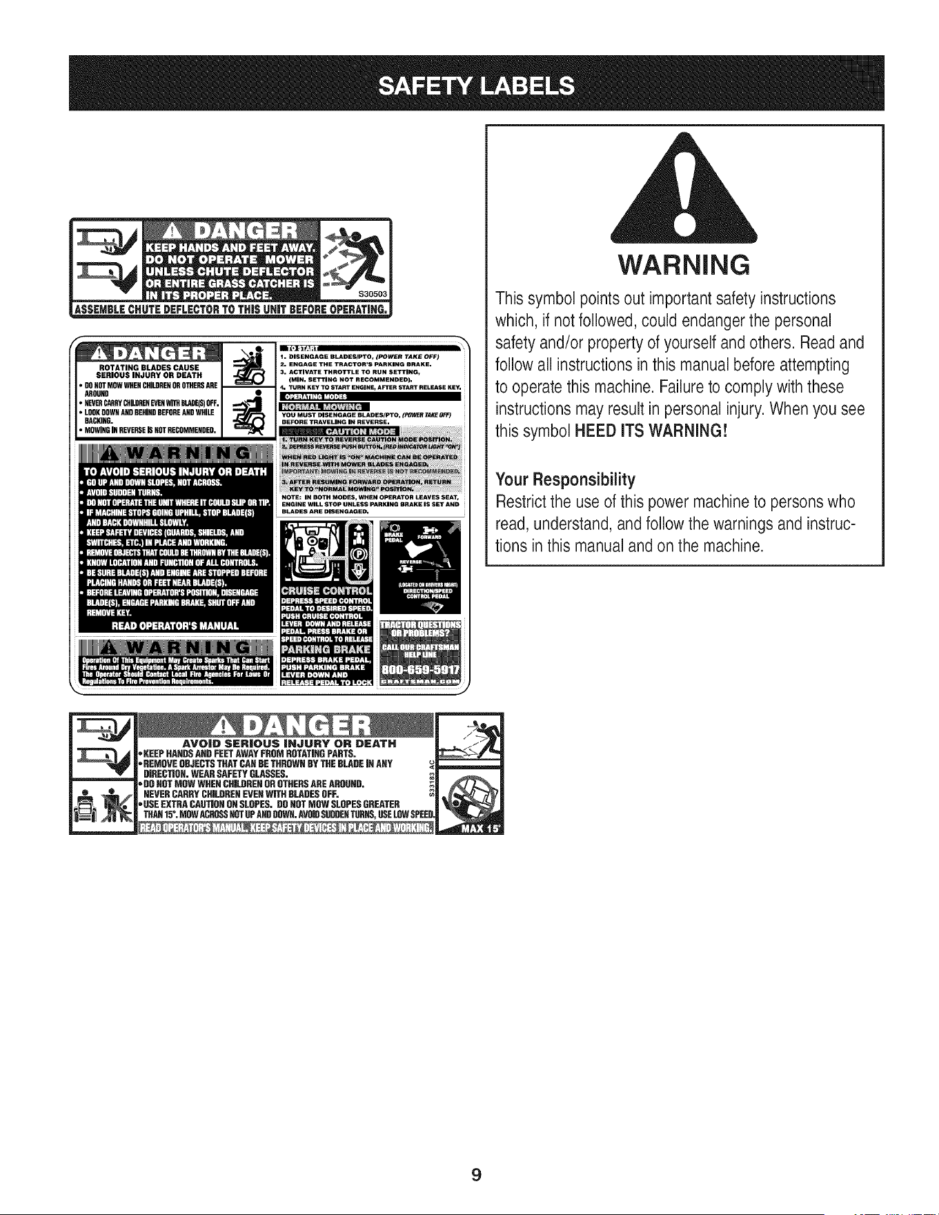
ROTATING BLADES CAUSE
_HEN CHI_REHOROTHERSARE
AROUND I •
_HILDREN EVENWITHBLADE(S)OFF.J
_HIND BEFOREANDWHILE J
BACKING. I
_RSE ISNOT RECOMMENDED, I
1. DISENGAGE BLADES/PTO, (POWER TAKE OFF)
2. ENGAGE THE TRACTOR'S PARKING BRAKE.
3. ACTIVATE THROTTLE TO RUN SETTING,
(MAN. SETTING NOT RECOMMENDED).
4. TURN KEY TO START ENGINE, AFTER START RELEASE KEY.
YOU MUST DISENGAGE SLADES/PTO, (FO_ TAKE OFF)
BEFORE TRAVELING IN REVERSE.
WARNING
This symbol points out important safety instructions
which, if not followed, could endanger the personal
safety and/or property of yourself and others. Readand
follow all instructions in this manual before attempting
to operatethis machine. Failureto comply with these
instructions may result in personal injury. When you see
this symbol HEED ITS WARNING!
Your Responsibility
Restrictthe use of this power machineto persons who
read, understand, and follow the warnings and instruc-
tions in this manualand on the machine.
AVO|D SER|OUS |HJURY OR DEATH
"KEEPHANDSAHDFEETAWAYFROMROTATIRGPARTS.
'=REMOVEOBJECTSTHATCARDETHROWNBYTHEBLADEJRANY
DIRECTIOR.WEARSAFETYGLASSES.
'=DOROTMOWWHENCHILDRENOROTHERSAREAROUND,
NEVERCARRYCHILDRENEVERWITHBLADESOFF.
"USEEXTRACAUTIORONSLOPES.DOROTMOWSLOPESGREATER
THAH15°. MOWACROSSHOTUPANDDDWR.AVOIDSUDDERTURNS,USELOWSPEE
m
m
9
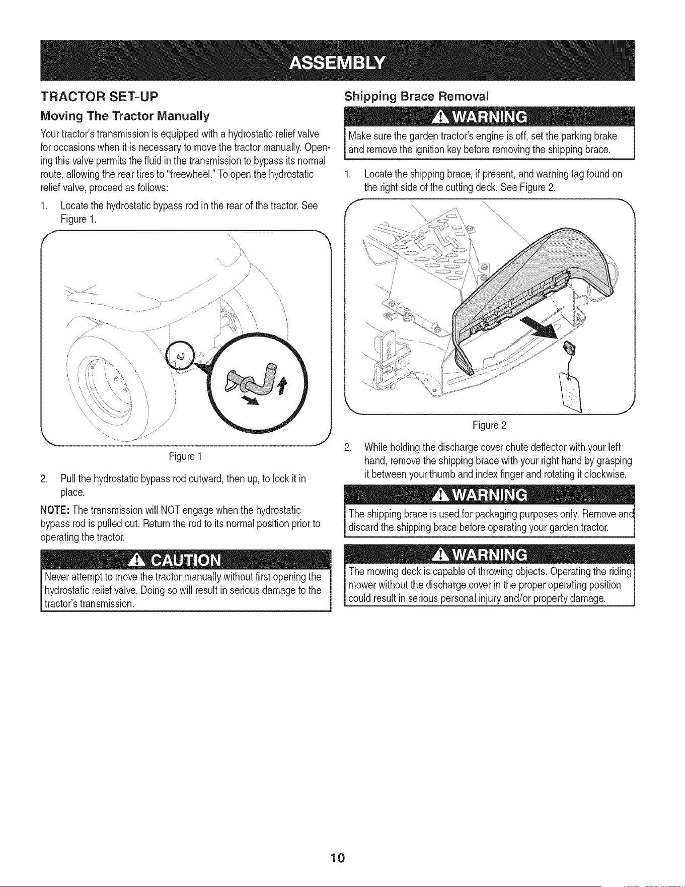
TRACTOR SET-UP
Moving The Tractor Manually
Yourtractor'stransmissionis equippedwitha hydrostaticreliefvalve
for occasionswhenit is necessaryto movethe tractormanually.Open-
ingthisvalvepermitsthe fluidin the transmissionto bypassits normal
route,allowingthe rear tiresto "freewheel."Toopenthe hydrostatic
reliefvalve,proceedas follows:
1. Locatethe hydrostaticbypassrod in the rearof thetractor.See
Figure1.
Shipping Brace Removal
Makesurethe gardentractor'sengineis off, setthe parkingbrake
and removethe ignitionkey beforeremovingthe shippingbrace.
1. Locatethe shippingbrace,if present,and warningtag foundon
the right side of the cutting deck. See Figure 2.
f _
,\
Figure2
Figure1
2. Pull the hydrostaticbypassrodoutward,then up,to lock itin
place.
NOTE:The transmissionwill NOTengagewhenthe hydrostatic
bypassrod is pulledout. Returnthe rod to its normalpositionprior to
operatingthe tractor.
2. Whileholdingthe dischargecoverchute deflectorwith yourleft
hand, removethe shippingbracewith yourright handby grasping
it betweenyourthumb and indexfingerand rotatingit clockwise.
The shippingbraceis usedfor packagingpurposesonly. Removeant
discardthe shippingbracebeforeoperatingyour gardentractor.
Neverattemptto movethetractormanuallywithoutfirst openingthe
hydrostaticreliefvalve.Doingsowill resultinseriousdamageto the
tractor'stransmission.
The mowingdeck is capableof throwingobjects.Operatingthe riding
mowerwithoutthe dischargecoverin theproperoperatingposition
could resultin seriouspersonalinjuryand/orpropertydamage.
10
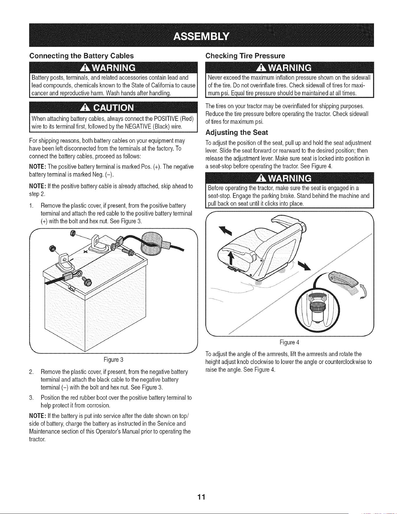
Connecting the Battery Cables Checking Tire Pressure
Batteryposts,terminals,and relatedaccessoriescontainlead and
leadcompounds,chemicalsknownto the Stateof Californiato cause
cancerandreproductiveharm.Washhandsafter handling.
Whenattachingbatterycables,alwaysconnectthe POSiTiVE(Red)
wire to its terminalfirst,followedbythe NEGATIVE(Black)wire.
For shippingreasons,bothbatterycablesonyourequipmentmay
havebeenleft disconnectedfrom theterminalsat the factory.To
connectthe batterycables,proceedas follows:
NOTE:The positivebatteryterminalis markedPos.(+). The negative
batteryterminalis markedNeg.(-).
NOTE: If the positivebatterycableis alreadyattached,skipaheadto
step2.
1. Removetheplasticcover,if present,fromthe positivebattery
terminalandattachthe redcable to the positivebatteryterminal
(+)with the bolt and hexnut.See Figure3.
f
.\
Figure3
2. Removetheplasticcover,if present,fromthe negativebattery
terminalandattachthe blackcableto the negativebattery
terminal(-) withthe bolt andhex nut.SeeFigure3.
3. Positionthe red rubberbootoverthe positivebatteryterminalto
helpprotectit fromcorrosion.
NOTE: If the batteryis put intoserviceafterthe dateshownontop/
sided battery,chargethe batteryas instructedinthe Serviceand
Maintenancesectionof this Operator'sManualpriorto operatingthe
tractor.
Neverexceedthe maximuminflationpressureshownon thesidewall
of the tire.Do notoverinfiatetires. Checksidewallof tires for maxi-
mumpsi.Equaltire pressureshouldbemaintainedat all times.
The tires on yourtractormaybeoverinfiatedfor shippingpurposes.
Reducethe tire pressurebeforeoperatingthe tractor.Checksidewall
of tires for maximumpsi.
Adjusting the Seat
Toadjust the positionof the seat,pullupandholdthe seat adjustment
lever.Slidethe seatforwardor rearwardto thedesiredposition;then
releasethe adjustmentlever.Makesure seatis lockedintopositionin
a seat-stopbeforeoperatingthe tractor.See Figure4.
Beforeoperatingthe tractor,makesurethe seatis engagedina
seat-stop.Engagethe parkingbrake.Standbehindthe machineand
pull backon seatuntil it clicksintoplace.
Figure4
Toadjust the angleof the armrests,liftthe armrestsand rotatethe
heightadjustknobclockwiseto lowertheangleor counterclockwiseto
raisethe angle.SeeFigure4.
11
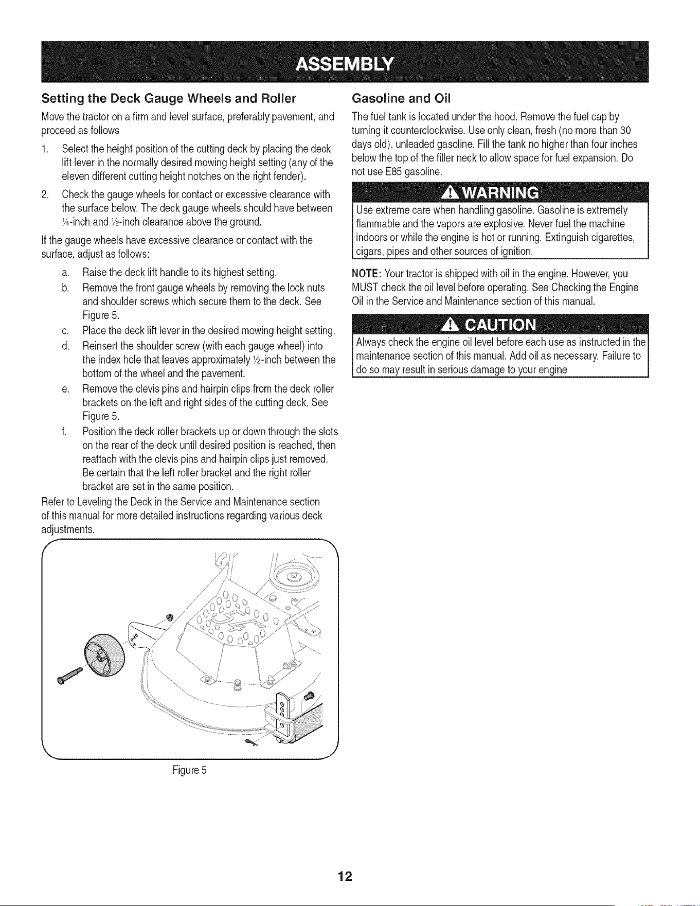
Setting the Deck Gauge Wheels and Roller
Movethe tractoron a firm and levelsurface,preferablypavement,and
proceedas follows
1. Selectthe heightpositionof the cuttingdeck byplacingthedeck
lift leverinthe normallydesiredmowingheightsetting(anyof the
elevendifferentcuttingheightnotcheson the rightfender).
2. Checkthe gaugewheelsforcontactor excessiveclearancewith
the surfacebelow.Thedeckgaugewheelsshouldhavebetween
l_-inchand Y2-inchclearanceabovethe ground.
Ifthe gauge wheelshaveexcessiveclearanceor contactwiththe
surface,adjustas follows:
a. Raisethe decklift handleto itshighest setting.
b. Removethe frontgaugewheelsby removingthe locknuts
andshoulderscrewswhich securethemto the deck.See
Figure5.
c. Placethedecklift leverin thedesiredmowingheightsetting.
d. Reinsertthe shoulderscrew(witheach gaugewheel)into
the indexhole that leavesapproximatelyY2-inchbetweenthe
bottomof the wheeland the pavement.
e. Removethe clevispins andhairpinclipsfromthedeck roller
bracketson the left and right sidesof the cuttingdeck.See
Figure5.
f. Positionthe deck rollerbracketsup ordownthroughthe slots
onthe rear of the deck untildesiredpositionisreached,then
reattachwiththe clevispinsand hairpinclipsjust removed.
Becertainthatthe leftrollerbracketand the rightroller
bracketareset inthe same position.
Referto Levelingthe Deckin theServiceand Maintenancesection
of this manualfor moredetailedinstructionsregardingvariousdeck
adjustments.
f
Gasoline and Oil
The fueltank islocatedunderthe hood.Removethe fuel cap by
turningit counterclockwise.Useonlyclean, fresh(no morethan30
daysold), unleadedgasoline.Fillthe tanknohigherthan fourinches
belowthe top of thefiller neckto allowspacefor fuel expansion.Do
not use E85gasoline.
Useextremecarewhen handlinggasoline.Gasolineis extremely
flammableandthevaporsare explosive.Neverfuel the machine
indoorsor whilethe engineis hotor running.Extinguishcigarettes,
cigars,pipesandothersourcesof ignition.
NOTE: Yourtractorisshippedwithoil inthe engine.However,you
MUSTcheckthe oillevelbeforeoperating.SeeCheckingthe Engine
Oil inthe Serviceand Maintenancesectionof thismanual.
Alwayscheckthe engineoil levelbeforeeach useas instructedin the
maintenancesectionof this manual.Add oil as necessary.Failureto
do so may resultin seriousdamageto yourengine
Figure5
12
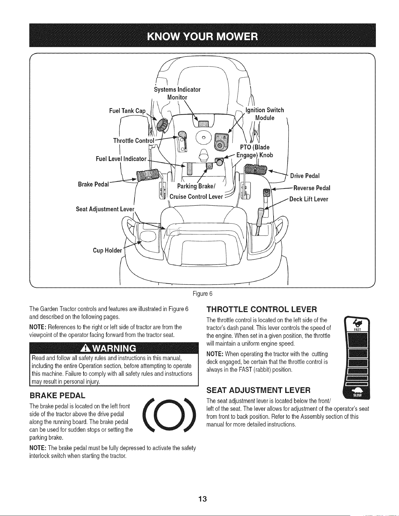
f
FuelTank Cap
Throttle
I
Fuel LevelIndicator
Systems Indicator
Monitor
ignition Switch
Module
PTO(Blade
Knob
Brake Pedal
Seat AdjustmentLever
Parking Brake/
Cruise Control Lever
DrivePedal
Pedal
Lift Lever
Cup Holder"
\
Figure6
TheGardenTractorcontrolsand featuresare illustratedin Figure6
anddescribedon thefollowingpages.
NOTE: Referencesto the rightor Idt sideof tractorare from the
viewpointof theoperatorfacingforwardfromthe tractorseat.
Readand followall safety rulesandinstructionsinthismanual,
includingtheentireOperationsection,beforeattemptingto operate
this machine.Failureto complywith all safety rulesand instructions
mayresultin personalinjury.
BRAKE PEDAL
Thebrakepedalis locatedonthe leftfront
sideof the tractorabovethe drivepedal
alongthe runningboard.Thebrakepedal
can be usedfor suddenstopsor settingthe
parkingbrake.
NOTE:The brakepedalmust befullydepressedto activatethe safety
interlockswitchwhenstartingthetractor.
THROTTLE CONTROL LEVER
The throttlecontrol is locatedonthe left sideof the
tractor'sdashpanel.Thislevercontrolsthe speedof
the engine.When setina givenposition,the throttle
will maintaina uniformenginespeed.
NOTE:Whenoperatingthe tractorwith the cutting
deckengaged,be certain that the throttlecontrolis
alwaysin the FAST(rabbit)position.
SEAT ADJUSTMENT LEVER
The seat adjustmentleveris locatedbelowthe front/
Idt of the seat.The leverallowsfor adjustmentof the operator'sseat
fromfrontto back position.Referto the Assemblysectionof this
manualfor moredetailedinstructions.
13
DECK LiFT LEVER
Foundon yourtractor'srightfender,the
decklift leveris usedto changethe height
of the cuttingdeck. Touse,movethe lever
to the left,then placein the notchbest
suitedfor yourapplication.
IGNITION SWITCH MODULE
Tostart theengine,insertthe keyinto
the ignitionswitchand turnclockwise
to the STARTposition.Releasethe
keyintothe NORMALMOWINGMODE
positiononcethe enginehas fired.
Tostop theengine,turnthe ignitionkey
counterclockwiseto the STOPposition.
(BladeEngageknob),setparkingbrake,stop engineand remove
to preventunintendedstarting.
Priorto operatingthe tractor,referto bothSafetyInterlockSwitches
andStartingThe Enginein the Operationsectionof thismanual
fordetailedinstructionsregardingthe IgnitionSwitchModuleand
[operatngthe tractor n REVERSECAUTON MODE.
DRIVE PEDAL
Thedrivepedalis locatedon the rightsideof
thetractor,along the runningboard.Pressthe
drivepedalforwardto causethe tractorto travel
forward.Groundspeedis alsocontrolledwith
thedrive pedal.Thefurtherforwardthe pedal is
pivoted,the fasterthe tractorwilltravel.The pedal
will returnto its originalpositionwhenit's not
pressed.
REVERSE PEDAL
The reversepedal is locatedonthe right sideof the
tractoralongthe runningboard. Groundspeedis
alsocontrolledwith the reversepedal.Thefurther
downwardthe pedalis pivoted,the fasterthe
tractorwill travel.Thepedalwill returnto its original
positionwhenit's not pressed.
|
SYSTEMS INDICATOR MONITOR/HOUR
METER LCD
Whenthe ignitionkey is
rotatedout of the STOP
positionbut not intothe START
position,thesystem'sindicator
monitordisplaysthe battery's
output,in volts,on its LCDfor
approximatelyfiveseconds,
afterwhichit displaysan hour
glassandthe hoursof tractor
operation.Oncethe tractoris
started,the monitorcontinually
displaysan hourglassandthe
0
I
o (r) o
hoursof tractoroperationon its LCD.
NOTE: Hoursof tractoroperationare recordedanytimethe ignition
keyis rotatedout of the STOPposition,regardlessof whetherthe
engineis started.
The IndicatorMonitorwillalso remindthe operatorof maintenance
intervalsfor changingthe engineoil. The LCDwill alternatelyflash
the recordedhours,"CHG"and"OIL."for five minutes,after every50
hoursof recordedoperationelapse.The maintenanceintervallasts
for two hours(from 50-52, 100-102,150-152,etc.).The LCDwill also
flashas describedabovefor fiveminuteseverytime the tractor's
enginehasbeen startedduringthismaintenanceinterval.Beforethe
intervalexpires,changethe engineoilas instructedin the Serviceand
Maintenancesectionof this Operator'sManual.
Brake
if the Brakelightilluminateswhenattemptingto start the tractor's
engine,depressthe brakepedal.
PTO (Blade Engage)
Ifthe PTOlight illuminateswhenattemptingto startthe tractor's
engine,movePTOknobinto thedisengaged(OFF)position.
Oil
Itis normalfor the Oillightto illuminatewhile theengine is cranking
duringstart-up,but if it illuminatesduringoperation,whilethe engineis
running,stopthe tractorimmediatelyandcheckthe engineoil levelas
instructedinthis Operator'sManual.
Battery
Itis normalfor the Batterylight to illuminatewhilethe engineis
crankingduringstart-up,but if it illuminatesduringoperation,whilethe
engineis running,the batteryis inneedof a chargeorthe engine's
chargingsystemis notgeneratingsufficientamperage.Chargethe
batteryas instructedin the Servicesectionof thismanualor havethe
chargingsystemcheckedby aSearsor otherqualifiedservicedealer.
14
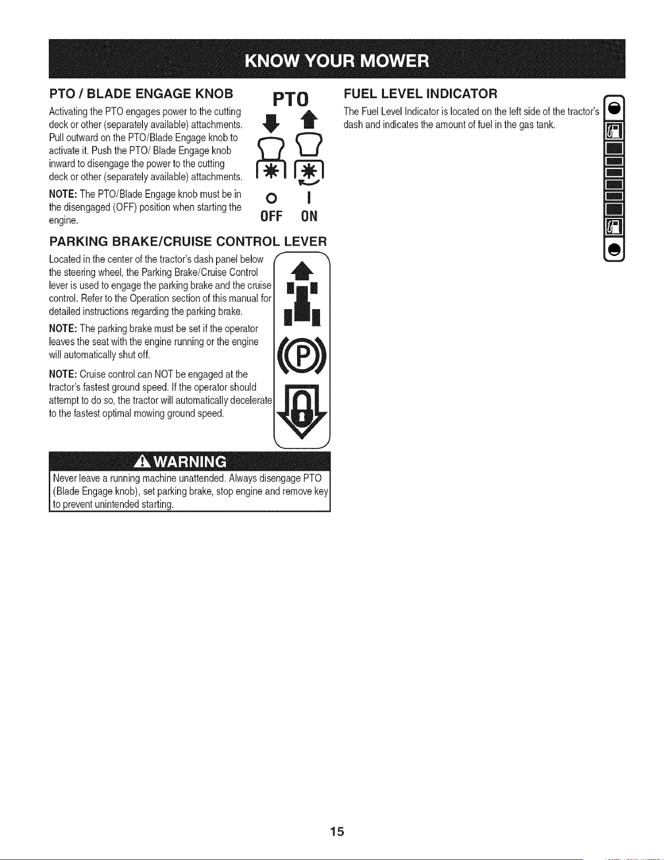
PTO / BLADE ENGAGE KNOB
Activatingthe PTOengagespowerto the cutting
deckorother (separatelyavailable)attachments.
Pulloutwardon the PTO/BladeEngageknobto
activateit.Pushthe PTO/Blade Engageknob
inwardto disengagethe powerto the cutting
deckorother (separatelyavailable)attachments.
NOTE:The PTO/BladeEngageknobmustbe in
the disengaged(OFF)positionwhenstartingthe
engine.
PTO
OFF ON
FUEL LEVEL INDICATOR
The FuelLevelIndicatoris locatedon the left sideof the tractor's
dashand indicatestheamountof fuel inthe gas tank.
PARKING BRAKE/CRUISE CONTROL LEVER
Locatedinthe centerof the tractor'sdash panelbelow
the steeringwheel,the ParkingBrake/CruiseControl
leveris usedto engagethe parkingbrakeandthe cruise
control.Referto the Operationsectionof thismanualfor
detailedinstructionsregardingthe parkingbrake.
NOTE:The parkingbrakemustbe setif the operator
leavesthe seatwith the enginerunningorthe engine
will automaticallyshutoff.
NOTE:Cruisecontrolcan NOTbe engagedat the
tractor'sfastestgroundspeed.If the operatorshould
attemptto do so,the tractorwill automaticallydecelerate
to the fastestoptimalmowinggroundspeed.
Neverleavea runningmachineunattended.AlwaysdisengagePTO
(BladeEngageknob),setparkingbrake,stop engineand removekey
to preventunintendedstarting.
15
SAFETY iNTERLOCK SWITCH ES
Thistractoris equippedwitha safetyinterlocksystemfor the protection
of the operator.Ifthe interlocksystemshouldevermalfunction,do not
operatethe tractor.Contacta Searsorotherqualifiedservicedealer.
• The safetyinterlocksystempreventstheenginefromcrankingor
startingunlessthe parkingbrakeis engaged,and the PTO(Blade
Engage)knobis in thedisengaged(OFF)position.
Theenginewill automaticallyshutoffif theoperatorleavesthe
seatbeforeengagingthe parkingbrake.
• TheelectricPTO(Blade Engage)clutchwill automaticallyshut
off if the operatorleavesthe tractor'sseatwith the PTO(Blade
Engage)knobin the engaged(ON) position,regardlessof
whetherthe parkingbrakeisengaged.
• Withthe ignitionkey inthe NORMALMOWINGposition,the
electricPTO(BladeEngage)clutchwillautomaticallyshut off if
the PTO(BladeEngage)knobis movedintothe engaged(ON)
positionwiththedrive pedalinpositionfor reversetravel.
Do notoperatethe tractorif the interlocksystemis malfunctioning.
Thissystemwasdesignedfor your safetyandprotection.
STARTING THE ENGINE
NOTE: Referto GasandOil inthe Assemblysectionof thismanual
for Gasolinefill-upinstructions.Referto Checkingthe EngineOil inthe
Serviceand Maintenancesectionof this manualfor oilfill-up instruc-
tions.
1. Insertthe tractorkeyintothe ignitionswitchmodule.
2. Placethe PTO(BladeEngage)knobin the disengaged(OFF)
position.
3. Engagethe tractor'sparkingbrake.
4. Movethe throttlecontrolintoa minimum50%operatingspeed.
Note: Thistractoris equippedwith an electronicFuelManage-
ment(EFM)system,also referredto as an electricchoke.No
actionis requiredto activatethe choke.Simplyplacethe throttle
inat minimum50% orhigherto startthe engine.
.
Turnthe ignitionkeyclockwiseto the STARTposition.After
theengine starts,releasethe key.It will returnto the NORMAL
MOWINGposition.
Do NOThold the keyinthe STARTpositionfor longerthan ten
secondsat a time.Doingso maycause damageto yourengine's
electricstarter.
STOPPING THE ENGINE
Ifyou strikea foreignobject,stopthe engineand disconnectthe
sparkplugwire(s). Thoroughlyinspectthe machinefor anydamage.
Repairthedamagebeforerestartingandoperating.
1. If the bladesare engaged,placethe PTO/BladeEngageknobin
the disengaged(OFF) position.
2. Placethe throttle/chokecontrollevernearthe SLOWposition.
3. Turnthe ignitionkeycounterclockwiseto the STOPposition.
4. Removethe keyfromthe ignitionswitchto preventunintended
starting.
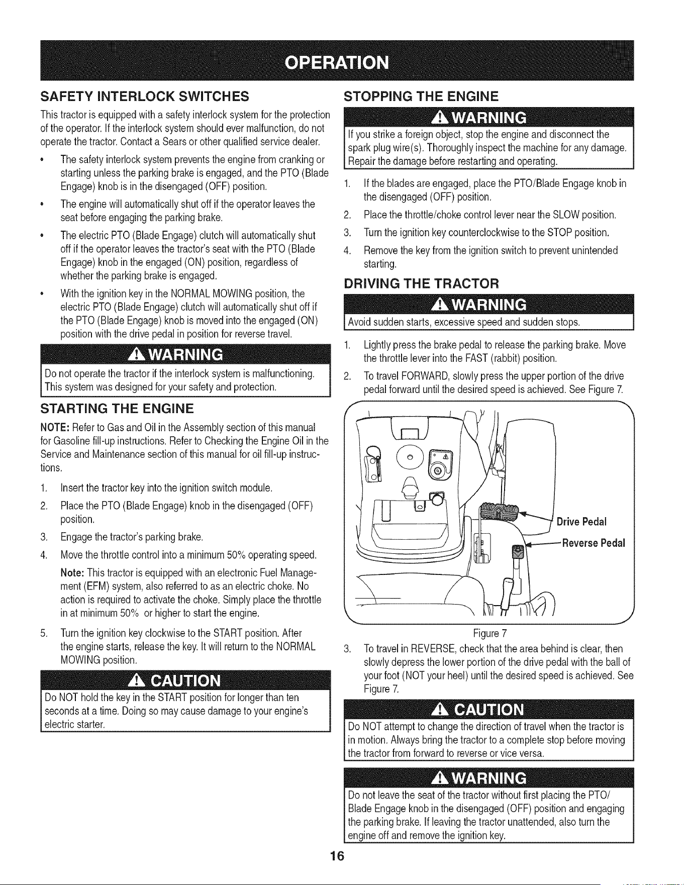
DRIVING THE TRACTOR
Avoidsuddenstarts,excessivespeedand suddenstops.
1. Lightlypressthe brakepedalto releasethe parkingbrake.Move
the throttleleverintothe FAST(rabbit)position.
2. TotravelFORWARD,slowlypressthe upper portionof the drive
pedalforwarduntilthe desiredspeedis achieved.See Figure7.
,
Figure7
3. Totravelin REVERSE,checkthat the areabehindis clear,then
slowlydepressthe lowerportionof the drivepedalwiththe ballof
yourfoot (NOTyourheel)untilthe desiredspeedis achieved.See
Figure7.
DoNOTattemptto changethe directionof travel whenthetractoris
in motion.Alwaysbringthe tractorto a completestop beforemoving
the tractorfromforwardto reverseorviceversa.
Donot leavethe seat of the tractorwithoutfirst placingthe PTO/
BladeEngageknobin the disengaged(OFF)positionandengaging
the parkingbrake. If leavingthe tractorunattended,alsoturn the
engineoff andremovethe ignitionkey.
16
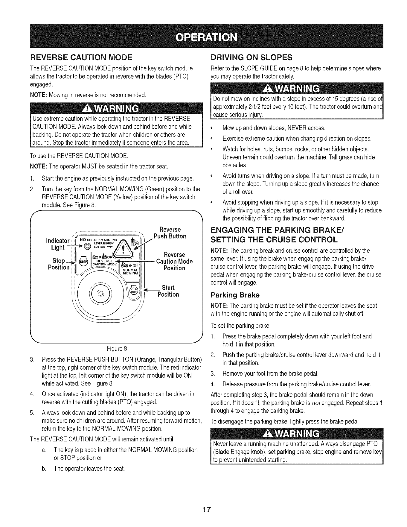
REVERSE CAUTION MODE
The REVERSECAUTIONMODEpositionof thekey switch module
allowsthe tractorto be operatedin reversewith the blades(PTO)
engaged.
NOTE: Mowingin reverseis not recommended.
Useextremecautionwhile operatingthe tractorin the REVERSE
CAUTIONMODE.Alwayslookdownand behindbeforeandwhile
backing.Do notoperatethe tractorwhenchildrenor othersare
around.Stopthe tractorimmediatelyif someoneentersthearea.
Touse the REVERSECAUTIONMODE:
NOTE:The operatorMUSTbe seatedinthe tractorseat.
1. Start theengineas previouslyinstructedon the previouspage.
2. Turnthe keyfromthe NORMALMOWING(Green)positionto the
REVERSECAUTIONMODE(Yellow)positionof the keyswitch
module.SeeFigure8.
F "
Reverse
Figure8
3. Pressthe REVERSEPUSHBUTTON(Orange,TriangularButton)
at the top,rightcornerof the keyswitchmodule.The redindicator
lightat the top, left cornerof the keyswitchmodulewillbe ON
whileactivated.See Figure8.
4. Onceactivated(indicatorlightON), the tractorcan bedrivenin
reversewiththe cuttingblades(PTO)engaged.
5. Alwayslookdownand behindbeforeand whilebackingup to
makesureno childrenare around.After resumingforwardmotion,
returnthe keyto the NORMALMOWINGposition.
The REVERSECAUTIONMODEwill remainactivateduntil:
a. Thekeyis placedin eitherthe NORMALMOWINGposition
orSTOPpositionor
b. Theoperatorieavesthe seat.
DRIVING ON SLOPES
Referto the SLOPEGUIDEon page8 to helpdetermineslopeswhere
you mayoperatethe tractorsafely.
Donot mowon inclineswitha slopein excessof 15degrees(a rise
approximately2-1/2feetevery10feet).The tractorcouldoverturnanc
causeseriousinjury.
• Mowup and down slopes,NEVERacross.
• Exerciseextremecautionwhenchangingdirectionon slopes.
• Watchfor holes,ruts,bumps,rocks,or otherhiddenobjects.
Uneventerraincouldoverturnthe machine.Tallgrass can hide
obstacles.
Avoidturns whendrivingon a slope.If a turnmustbe made,turn
downthe slope.Turningup a slopegreatly increasesthe chance
of a rollover.
Avoidstoppingwhen drivingup a slope.If itis necessaryto stop
whiledrivingup a slope,start upsmoothlyand carefullyto reduce
the possibilityof flippingthe tractoroverbackward.
ENGAGING THE PARKING BRAKE/
SETTING THE CRUISE CONTROL
NOTE:Theparkingbreakand cruisecontrolare controlledbythe
samelever.Ifusingthe brakewhenengagingthe parkingbrake/
cruisecontrollever,theparkingbrakewillengage.Ifusingthe drive
pedalwhenengagingthe parkingbrake/cruisecontrol lever,the cruise
controlwill engage.
Parking Brake
NOTE:Theparkingbrakemustbesetif theoperatorleavesthe seat
withthe engine runningor theenginewillautomaticallyshutoff.
To set the parkingbrake:
1. Pressthe brakepedalcompletelydownwith yourleftfootand
holditinthat position.
2. Pushthe parkingbrake/cruisecontrolleverdownwardandholdit
inthatposition.
3. Removeyourfootfromthe brakepedal.
4. Releasepressurefrom the parkingbrake/cruisecontrollever.
Aftercompletingstep3, the brakepedalshouldremaininthe down
position.If itdoesn't,the parkingbrakeis not engaged.Repeatsteps1
through4 toengagethe parkingbrake.
Todisengagethe parkingbrake,lightly pressthe brakepedal.
(BladeEngageknob),setparkingbrake,stopengineandremove
to preventunintendedstarting.
17
Cruise Control MOWING
Neverengagethe cruise controlleverwhiletravelingin reverse.
Toset the cruisecontrol:
1. Slowlypressthe upperportionof thedrive pedalwithyour right
footuntilthe desiredspeedisachieved.
2. Lightlypressthe parkingbrake/cruisecontrolleverdownwardand
holdit in that position.
3. Removeyour footfromthe drive pedal.
4. Releasepressurefromthe parkingbrake/cruisecontrollever
Aftercompletingstep3, the drivepedal shouldremaininthe down
positionandthetractorwill maintainthe sameforwardspeed.If it
doesn't,the cruisecontrol is not engaged.Repeatsteps 1 through4 to
engagethecruise control.
Todisengagethe cruisecontrol,lightlypressthe drivepedalor the
brakepedal.
NOTE: Cruisecontrolcannot be set at the tractor'sfastestground
speed.If the operatorshouldattemptto do so,thetractorwill automati-
callydecelerateto thefastestoptimalmowinggroundspeed.
Tochangethe directionof travelfrom forwardto reversewhencruise
controlis engaged,pressthe brakepedal to disengagethe cruise
controlandbringthe tractorto a completestop.Thenslowlypressthe
reversepedalwiththe ball of yourfoot to travelinreverse.
ENGAGING THE PTO
Engagingthe PTOtransferspowerto thecuttingdeckor other
(separatelyavailable)attachments.Toengagethe PTO:
1. Movethe throttlecontrolleverto the FAST(rabbit)position.
2. Pull the PTO/BladeEngageknoboutwardintothe engaged(ON)
position.SeeFigure9.
NOTE:Alwaysoperatethe tractorwith the throttleleverin the FAST
(rabbit)positionforthe mostefficientuseof the cuttingdeck or other
(separatelyavailable)attachments.
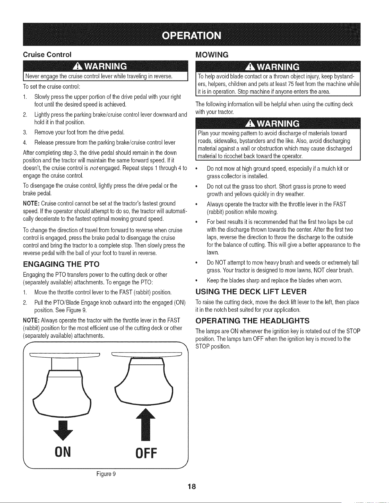
OFF
J
Figure9
To helpavoidbladecontactora thrownobjectinjury,keepbystand-
ers,helpers,childrenand petsat least75feetfromthe machinewhile
it is in operation.Stopmachineif anyoneentersthe area.
The followinginformationwill be helpfulwhenusingthe cuttingdeck
withyourtractor.
Planyourmowingpatternto avoiddischargeof materialstoward
roads,sidewalks,bystandersandthe like. Also,avoiddischarging
materialagainstawall or obstructionwhich may causedischarged
materialto ricochetbacktowardthe operator.
• Donot mowat highgroundspeed,especiallyif a mulchkitor
grasscollectoris installed.
• Donot cutthe grass tooshort. Shortgrassis proneto weed
growthandyellowsquicklyin dry weather.
• Alwaysoperatethetractorwith the throttleleverinthe FAST
(rabbit)positionwhilemowing.
• Forbest resultsit is recommendedthatthe first two laps becut
withthe dischargethrowntowardsthe center.Afterthe firsttwo
laps, reversethedirectionto throwthe dischargeto theoutside
for the balanceof cutting.This will givea better appearanceto the
lawn.
Do NOTattemptto mowheavy brushand weedsor extremelytall
grass.Yourtractoris designedto mowlawns,NOTclearbrush.
• Keepthe bladessharpand replacethe bladeswhenworn.
USING THE DECK LIFT LEVER
To raisethecuttingdeck, movethe deck lift leverto the left, thenplace
it inthe notch best suitedfor yourapplication.
OPERATING THE HEADLIGHTS
The lampsare ON wheneverthe ignitionkey is rotatedout of the STOP
position.Thelampsturn OFFwhenthe ignitionkey is movedto the
STOPposition.
18
Beforeperforminganytypeof maintenance/service,disengageall
controlsandstoptheengine.Waituntilallmovingpartshavecometo
acompletestop.Disconnectsparkplugwireandgroundit againstthe
engineto preventunintendedstarting.Alwayswearsafetyglassesduring
operationor whileperforminganyadjustmentsor repairs.
Followthe maintenanceschedulegivenbelow.This chart describes
serviceguidelinesonly.Usethe Service Logcolumnto keeptrack
of completedmaintenancetasks.To locate the nearest Parts &
Repair Service Centeror to scheduleservice,simplycontact
1-800-4-MY-HOME®.
BeforeEachUse
In the First FiveHours
Every10Hours
Every25 hours
Every50 hours
Annually
BeforeStorage
1. Engineoil level
2. Mufflerarea and controls
1. EngineOil
1. Hood/Dash air vents
2. Batteryterminals
3. Deckspindlesandidler
bracket
1. Air filter'sprecleaner*
2. Air filter*
3. Mid steeringarms,pivot
shafts,andaxles
4. Frontwheelbearings
5. Frontdeck wheels
1. Engineoil
2. Muffler
1. Air filter
2. Air filter'spre-cleaner
3. Sparkplug
4. Air coolingsystem*
5. Fuelfilter
6. SteeringGears
7. RearWheels
1. Hood/Dash air vents
2. Batteryterminals
3. Mid steeringarms,pivot
shafts,andaxles
4. Frontwheelbearings
5. Frontdeck wheels
6. Deckspindlesandidler
bracket
7. Pedalpivot points
1. Check
2. Clean
1. Change
1. Clean
2. Clean
3. Lubricate
1. Clean
2. Clean
3. Lubricate
4. Lubricate
5. Lubricate
1. Change
2. Check
1. Replace
2. Replace
3. Replace
4. Clean
5. Replace
6. Clean
7. Removeandgreaseaxles
1. Clean
2. Clean
3. Lubricate
4. Lubricate
5. Lubricate
6. Lubricate
7. Lubricate
*Servicemorefrequentlyunderdustyconditions.
(BladeEngageLever),engagethe parkingbrake,stopthe engine
removethe key to preventunintendedstarting.
If the enginehasbeenrecentlyrun,theengine,mufflerand sur-
roundingmetalsurfaceswill behotand can causeburnsto the skin.
Exercisecautionto avoidburns.
19
NOTE: Referencesto the rightor left sideof tractorarefromthe
viewpointof theoperatorfacing forwardfrom the tractorseat.
CUTTING DECK REMOVAL
To removethecuttingdeck, proceedas follows:
1. Placethe PTO/BladeEngageknobinthe disengaged(OFF)
positionandengagethe parkingbrake.
2. Lowerthe deckby movingthe deck liftleverintothe bottomnotch
onthe rightfender.
3. Locatethe PTOclutchunderthe frontof yourtractor.See
Figure10.
f
.
b. Pull the beltkeeperrodto the rightand downto remove.
c. Removethe deck belt fromaroundthe tractor'selectricPTO
clutch.
NOTE: If there is too muchtensionon thebelt for it to be easilyre-
movedfromtheelectric PTOclutch,cardully inserta 3/8" driveratchet
wrench(setto loosen) intothe squareholefound inthe Idt-handdeck
idlerbracketand pivotit towardthe tractor'srightsideto relievetension
on the belt. See Figure11.
Avoidpinchinginjuries.Neverplaceyourfingerson the idler springor
betweenthe beltanda pulleywhileremovingthe belt.
DeckIdler
Bracket
Insert Ratchet
Here
Figure11
.
6.
f
Lookingat thecuttingdeckfromthe left side of thetractor,locate
the deck supportpin on the rearleftsideof thedeck.
Pullthe deck supportpin outwardto releasethe deckfromthe
/
J
/
i
i
Deck Lift Arm
DeckSupportPin
'xx
'x
.
8.
Figure12
Repeatthe abovestepson the tractor'srightside.
Movethedeck lift leverintothe top notchto raisethedecklift
armsupandout of the way.
20
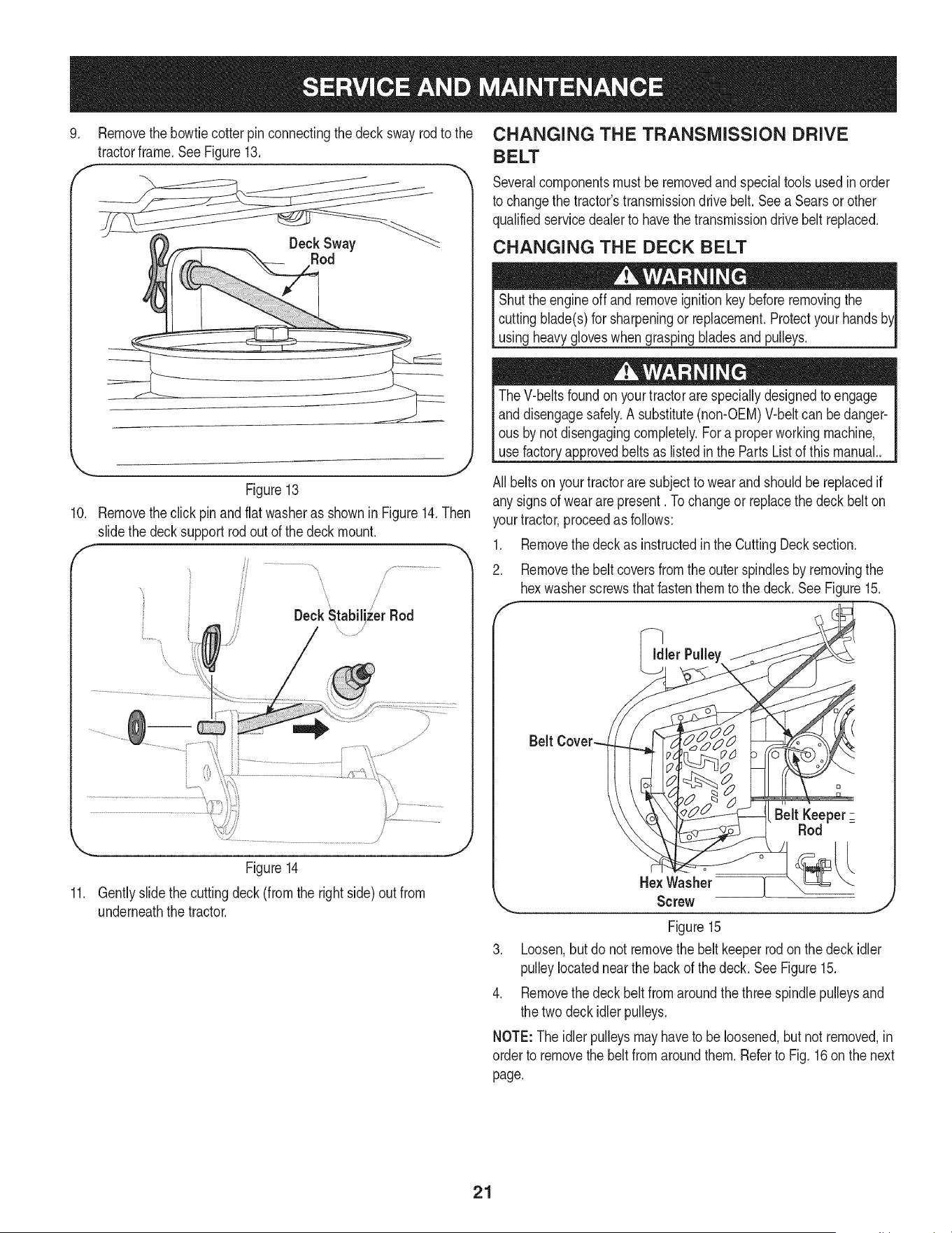
9. Removethebowtiecotterpin connectingthedeckswayrodto the
tractorframe.See Figure13.
Rod
Figure13
10. Removetheclick pinandflatwasheras shownin Figure14.Then
slidethe decksupportrodout of the deck mount.
, /
DeckNtabiliz_erRod
'\ /
...............................................................................i:':111"7
Figure14
11. Gentlyslidethe cuttingdeck(fromthe rightside)out from
underneaththe tractor.
CHANGING THE TRANSMISSION DRIVE
BELT
Severalcomponentsmustbe removedand specialtools usedinorder
to changethe tractor'stransmissiondrivebelt. See a Searsorother
qualifiedservicedealerto havethe transmissiondrivebelt replaced.
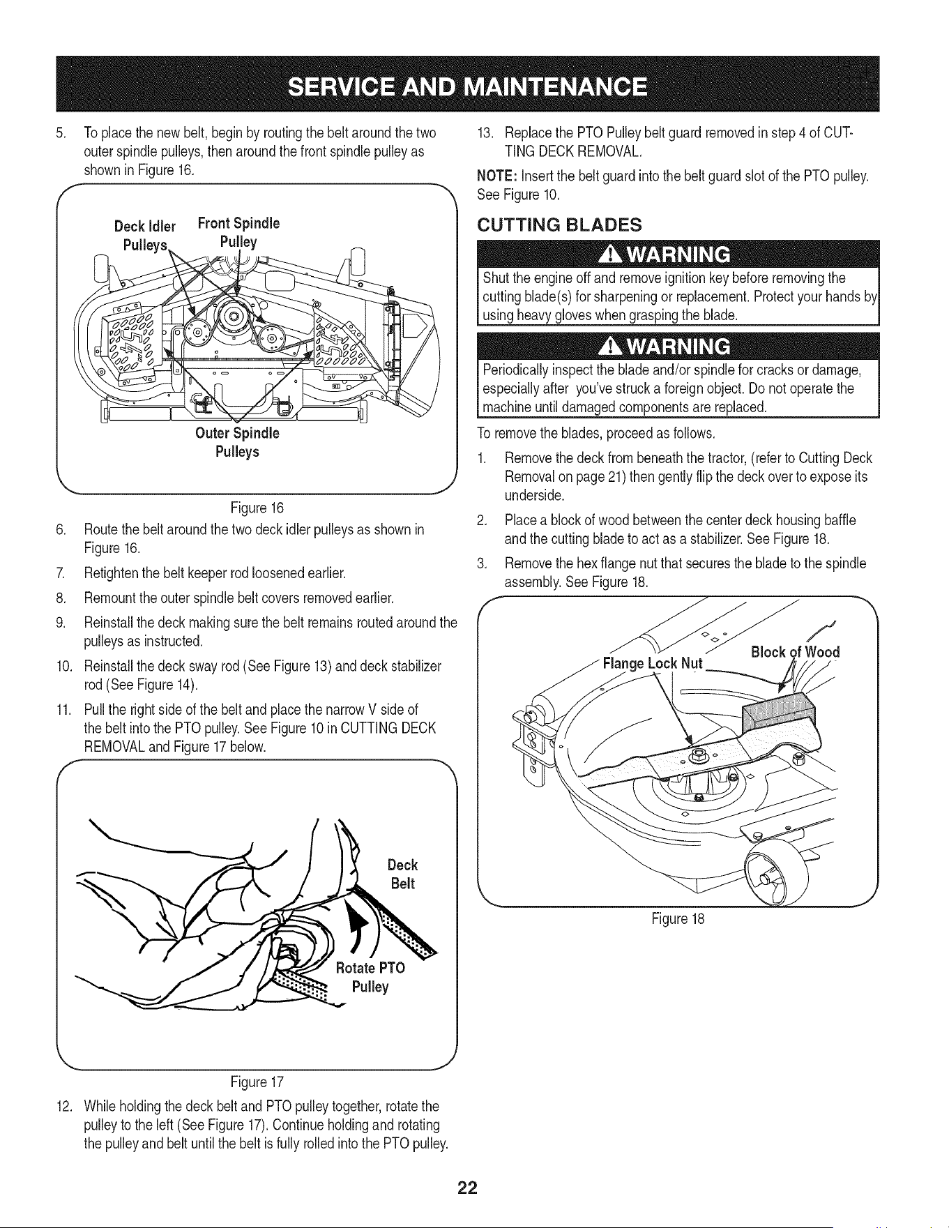
CHANGING THE DECK BELT
Shutthe engineoff andremoveignitionkey beforeremovingthe
cuttingblade(s)for sharpeningor replacement.Protectyourhands
usingheavygloveswhengraspingbladesand pulleys.
TheV-belts foundon yourtractorare speciallydesignedto engage
anddisengagesafely.A substitute(non-OEM)V-beltcan bedanger-
ous by notdisengagingcompletely.Fora properworkingmachine,
use factoryapprovedbeltsas listedin the PartsListof this manual..
All beltsonyourtractoraresubjectto wearand shouldbereplacedif
any signsof wear are present. Tochangeor replacethe deck belton
yourtractor,proceedas follows:
1. Removethe deckas instructedin the CuttingDecksection.
2. Removethe beltcoversfrom theouter spindlesby removingthe
hexwasherscrewsthat fastenthemto the deck.See Figure15.
f
_ler
Belt KeeperZ
Rod
HexWasher [
Screw
.J
Figure15
3. Loosen,but donot removethe belt keeperrodon the deckidler
pulleylocatednearthe backof the deck. SeeFigure15.
4. Removethe deckbeltfrom aroundthe threespindlepulleysand
the two deck idlerpulleys.
NOTE:Theidlerpulleysmayhaveto beloosened,butnot removed,in
orderto removethebelt fromaroundthem.Referto Fig. 16 on the next
page.
21
5. Toplacethe newbelt, begin by routingthe belt aroundthe two
outerspindlepulleys,then aroundthefront spindlepulleyas
shownin Figure16.
F
Z
8.
9.
10.
f
11.
Deck idler FrontSpindle
Pulley
Outer Spindle
Pulleys
J
Figure16
Routethe beltaroundthe twodeckidlerpulleysas shownin
Figure16.
Retightenthe belt keeperrodloosenedearlier.
Remounttheouter spindlebeltcoversremovedearlier.
Reinstallthe deck makingsurethe beltremainsroutedaroundthe
pulleysas instructed.
Reinstallthe deck swayrod(See Figure13)anddeckstabilizer
rod(SeeFigure14).
Pullthe rightside ofthe beltand placethe narrowV side of
the belt intothe PTOpulley.See Figure10in CUTTINGDECK
REMOVALandFigure17below.
Deck
Belt
RotatePTO
Pulley
13. Replacethe PTOPulleybelt guardremovedinstep4 of CUT-
TING DECKREMOVAL.
NOTE: Insertthe beltguardintothe beltguard slot of the PTOpulley.
See Figure10.
CUTTING BLADES
Shutthe engineoff andremoveignitionkey beforeremovingthe
cuttingblade(s)for sharpeningor replacement.Protectyourhands
usingheavy gloveswhengraspingthe blade.
Periodicallyinspectthe blade and/orspindlefor cracksordamage,
especiallyafter you'vestrucka foreignobject.Do notoperatethe
machineuntildamagedcomponentsare replaced.
To removethe blades,proceedas follows.
1. Removethe deckfrombeneaththe tractor,(referto CuttingDeck
Removalon page21)thengently flipthe deckoverto exposeits
underside.
2. Placea blockof woodbetweenthe centerdeckhousingbaffle
andthe cuttingbladeto actas a stabilizer.See Figure18.
3. Removethe hexflangenut thatsecuresthe bladeto the spindle
assembly.SeeFigure18.
e LockNut
f
Block
Figure18
... J
Figure17
12. Whileholdingthe deckbeltand PTOpulleytogether,rotatethe
pulleyto the left (See Figure17).Continueholdingand rotating
the pulleyand beltuntilthe belt isfully rolledintothe PTOpulley.
22
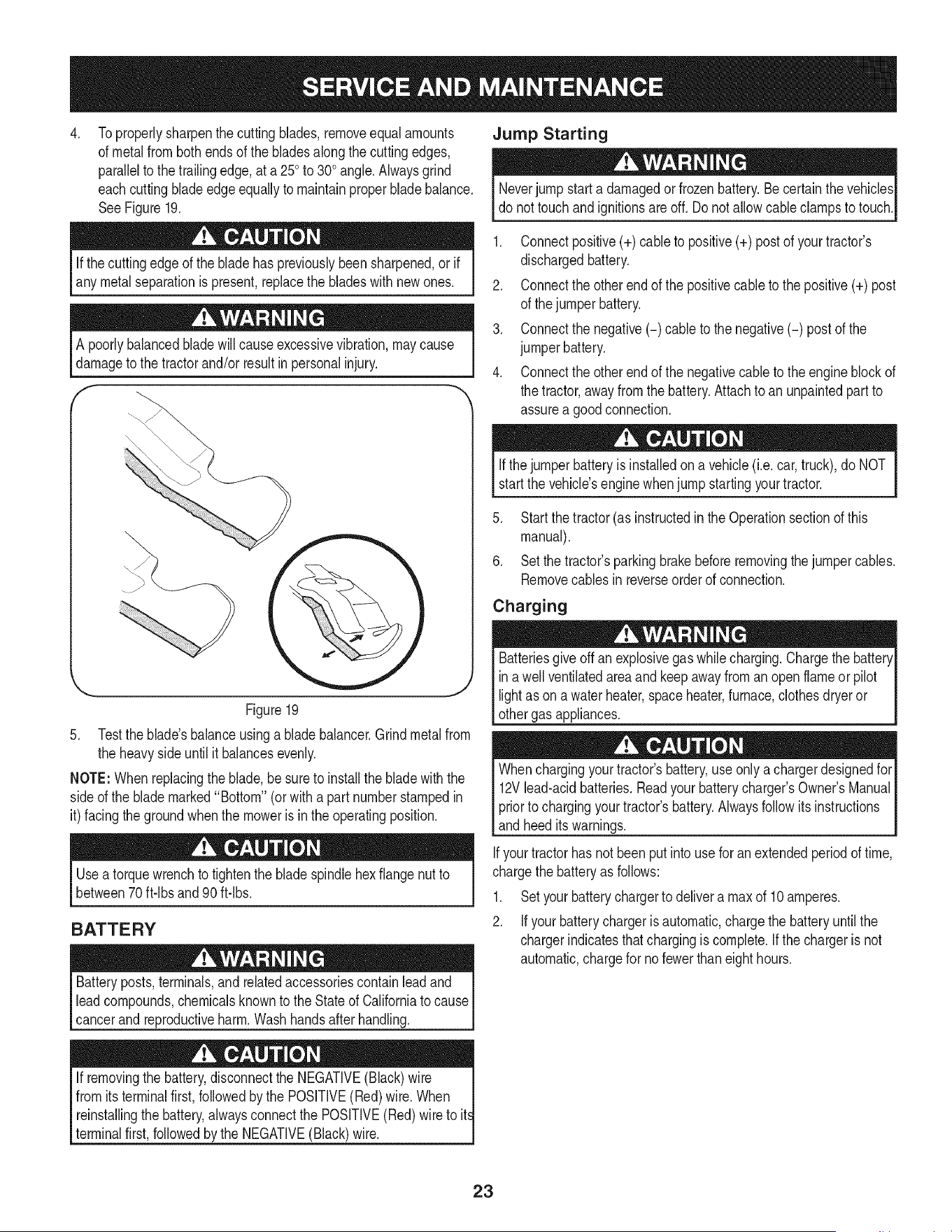
4. Jump Starting
Toproperlysharpenthe cuttingblades,removeequal amounts
of metalfrom both endsof the bladesalong the cuttingedges,
parallelto thetrailingedge,at a 250to 300angle.Alwaysgrind
eachcuttingbladeedgeequallyto maintainproperbladebalance.
SeeFigure19.
Neverjump starta damagedor frozenbattery.Be certainthe vehicles
do nottouch and ignitionsareoff. Donot allowcableclampsto touch.
Ifthe cuttingedgeof the bladehas previouslybeensharpened,or if
any metal separationis present,replacethe bladeswithnewones.
A poorlybalancedbladewillcause excessivevibration,maycause
damageto the tractorand/or resultinpersonalinjury.
f
\
Figure19
5. Testthe blade'sbalanceusinga bladebalancer.Grindmetalfrom
the heavyside untilit balancesevenly.
NOTE:Whenreplacingthe blade,besureto installthe bladewith the
sided the blademarked"Bottom"(orwitha part numberstampedin
it) facingthe groundwhenthe moweris in the operatingposition.
Useatorquewrenchto tightenthe blade spindlehexflange nutto
between70ft-lbs and 90 ft-lbs.
BATTERY
Batteryposts,terminals,and relatedaccessoriescontainlead and
leadcompounds,chemicalsknownto the Stateof Californiato cause
cancerandreproductiveharm.Washhandsafter handling.
If removingthe battery,disconnectthe NEGATIVE(Black)wire |
from itsterminalfirst,followedby the POSITIVE(Red)wire.When
t
reinstallingthe battery,alwaysconnectthe POSITIVE(Red)wire to it
terminalfirst,followedbythe NEGATIVE(Black)wire.
1. Connectpositive(+) cableto positive(+) postof your tractor's
dischargedbattery.
2. Connectthe otherend of the positivecableto the positive(+) post
of the jumperbattery.
3. Connectthe negative(-) cable to the negative(-) postof the
jumperbattery.
4. Connectthe otherend of the negativecableto the engineblock of
the tractor,awayfromthe battery.Attachto anunpaintedpartto
assurea goodconnection.
Ifthejumperbatteryis installedona vehicle(i.e.car,truck),do NOT
start the vehicle'senginewhenjump startingyourtractor.
5. Startthe tractor(as instructedin theOperationsectionof this
manual).
6. Setthe tractor'sparkingbrakebeforeremovingthejumpercables.
Removecablesinreverseorderof connection.
Charging
Batteriesgiveoff an explosivegas whilecharging.Chargethe battery[
in a wellventilatedareaand keepawayfroman openflameorpilot [
lightas on a waterheater,spaceheater,furnace,clothesdryeror [
othergas appliances. ..J
Whenchargingyourtractor'sbattery,use onlya chargerdesignedfor
12Vlead-acidbatteries.Readyourbatterycharger'sOwner'sManual
priorto chargingyourtractor'sbattery.Alwaysfollowitsinstructions
andheeditswarnings.
Ifyourtractorhas notbeenput intouse for an extendedperiodof time,
chargethe batteryas follows:
1. Setyourbatterychargerto delivera max of 10amperes.
2. Ifyour batterychargeris automatic,chargethe batteryuntilthe
chargerindicatesthatchargingis complete.If thechargeris not
automatic,chargefor nofewerthaneighthours.
23
FUSE
Beforeservicing,repairing,or inspecting,alwaysdisengagePTO
(BladeEngageknob),setparkingbrake,stop engineand remove
to preventunintendedstarting.
Afuse isinstalledinyourtractor'swiringharnessto protectthe trac-
tor'selectricalsystemfrom damagecausedbyexcessiveamperage.
Ifthe electricalsystemdoesnot function,or yourtractor'senginewill
notcrank,first checkto becertainthatthe fusehasnot blown.It is
locatedunderthe hood,mountedbehindthe top of the dashpanel on
the supportbar.
Alwaysusea replacementfuse with the sameamperagecapacityas
the blownfuse.
TIRES
Neverexceedthe maximuminflationpressureshownon the sidewall
of thetire.
Referto the tire sidewallfor exacttire manufacturer'srecommendedor
maximumpsi. Donot overinfiate.Uneventire pressurecouldcause the
cuttingdeck to mowunevenly.
MAINTENANCE
Beforeperformingany maintenanceor repairs,disengagePTO,set
parkingbrake,stopengineand removekeyto preventunintended
starting.
CLEANING THE TRACTOR
Anyfuel oroil spilledon the machineshouldbe wipedoff promptly.Do
NOTallowdebristo accumulatearoundthe coolingfinsof the engine,
thetransmission'scoolingfan or on any otherpartof the machine,
especiallythe beltsand pulleys.
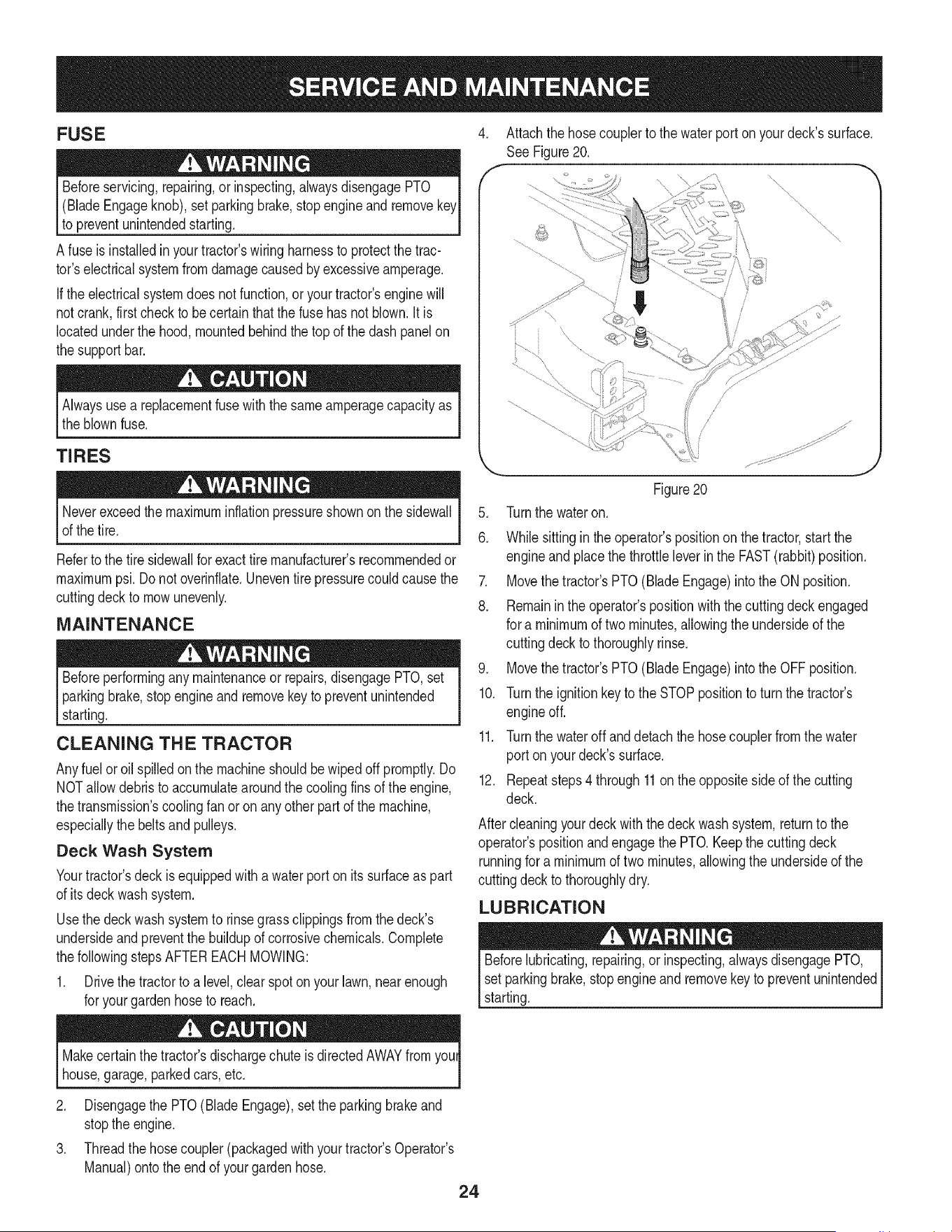
Deck Wash System
Yourtractor'sdeckis equippedwith a water port onitssurfaceas part
of itsdeck wash system.
Usethedeck wash systemto rinsegrass clippingsfrom the deck's
undersideandpreventthe buildupof corrosivechemicals.Complete
thefollowingstepsAFTEREACHMOWING:
1. Drivethe tractorto a level,clearspot on your lawn,nearenough
for yourgardenhoseto reach.
4. Attachthe hosecouplerto thewater porton yourdeck'ssurface.
See Figure 20.
\,
"\,
............. j
.
6.
Figure20
Turnthe wateron.
Whilesittingin the operator'spositionon the tractor,start the
engineand placethe throttleleverin the FAST(rabbit)position.
7. Movethetractor'sPTO(BladeEngage)intothe ON position.
8. Remainin theoperator'spositionwiththe cuttingdeckengaged
for a minimumof twominutes,allowingthe undersideof the
cuttingdeck to thoroughlyrinse.
9. Movethetractor'sPTO(BladeEngage)intothe OFFposition.
10. Turnthe ignitionkey to the STOPpositionto turn the tractor's
engineoff.
11. Turnthe wateroffanddetachthe hosecouplerfromthewater
port on yourdeck'ssurface.
12. Repeatsteps4 through11on the oppositesideof the cutting
deck.
Aftercleaningyourdeck with the deckwashsystem,returnto the
operator'spositionandengagethe PTO.Keepthe cuttingdeck
runningfor a minimumof twominutes,allowingthe undersideof the
cuttingdeck to thoroughlydry.
LUBRICATION
Beforelubricating,repairing,orinspecting,alwaysdisengagePTO,
setparkingbrake,stopengine andremovekeyto preventunintended
starting.
Makecertainthe tractor'sdischargechute isdirectedAWAYfromyoul
house,garage,parkedcars,etc.
2. Disengagethe PTO(Blade Engage),set the parkingbrakeand
stoptheengine.
3. Threadthe hosecoupler(packagedwithyourtractor'sOperator's
Manual)ontothe endof your gardenhose.
24
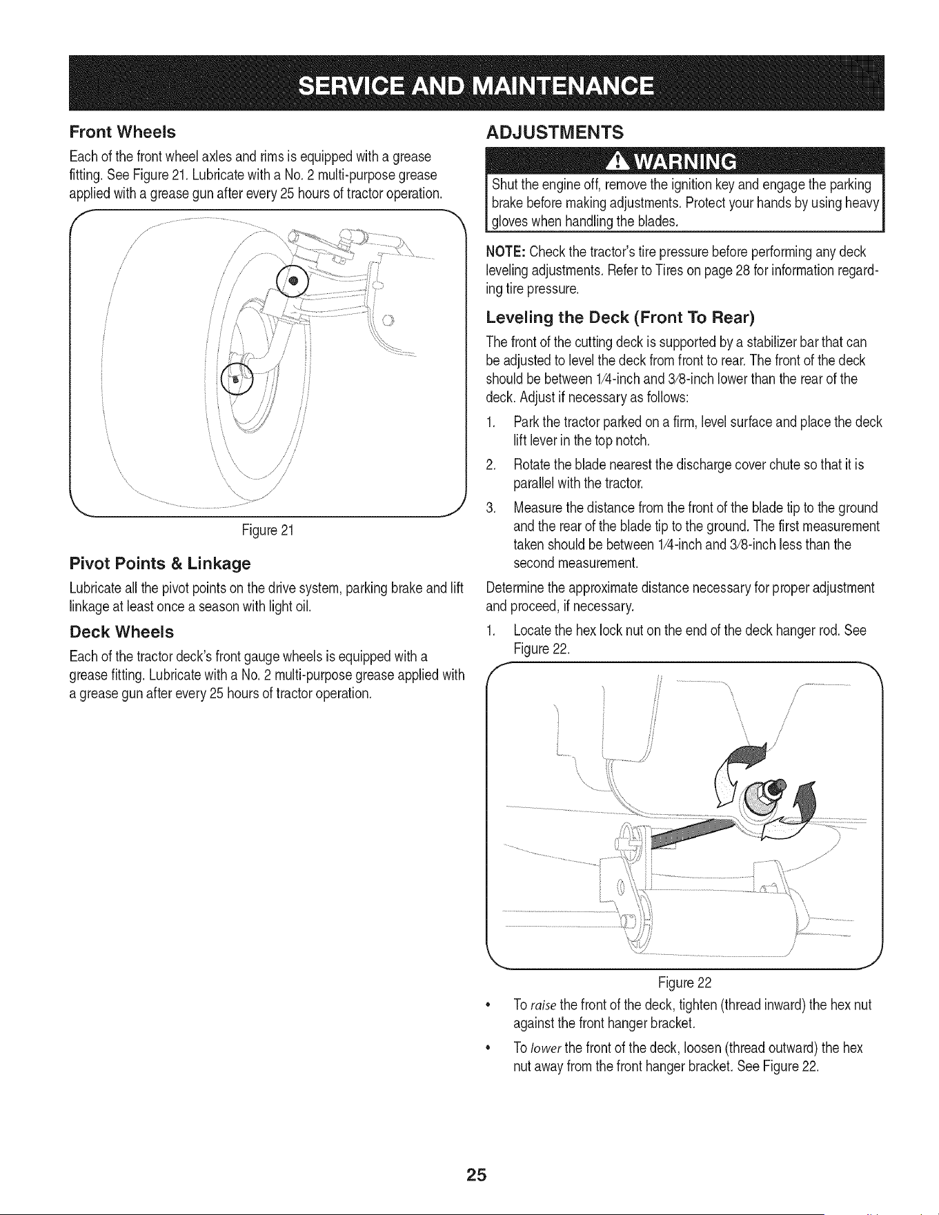
Front Wheels
Eachof the front wheelaxles and rimsisequippedwitha grease
fitting.SeeFigure21.Lubricatewith a No.2 multi-purposegrease
appliedwitha greasegun after every25 hoursof tractoroperation.
f -,
//
_7
/
/
/
/
/
i
i
J
Figure21
Pivot Points & Linkage
Lubricateall the pivotpointson thedrive system,parkingbrakeand lift
linkageat leastoncea seasonwith lightoil.
Deck Wheels
Eachof the tractordeck'sfrontgaugewheelsisequippedwitha
greasefitting.Lubricatewitha No.2 multi-purposegreaseappliedwith
a greasegunafterevery25 hoursof tractoroperation.
ADJUSTMENTS
Shutthe engineoff, removethe ignitionkeyandengagethe parking
brakebeforemakingadjustments.Protectyourhandsby usingheavy
gloveswhenhandlingthe blades.
NOTE:Checkthe tractor'stire pressurebeforeperformingany deck
levelingadjustments.Referto Tireson page28 for informationregard-
ingtirepressure.
Leveling the Deck (Front To Rear)
The front of thecuttingdeckis supportedby a stabilizerbarthatcan
beadjustedto levelthe deck from frontto rear.The frontof thedeck
shouldbe between1/4-inchand3/8-inchlowerthan the rearof the
deck.Adjust if necessaryas follows:
1. Parkthe tractorparkedon a firm, levelsurfaceand placethe deck
liftleverin thetop notch.
2. Rotatethe bladenearestthe dischargecoverchutesothat it is
parallelwiththe tractor.
3. Measurethedistancefromthe frontof the bladetip to theground
andthe rearof the bladetip tothe ground.Thefirst measurement
takenshouldbe between1/4-inchand3/8-inchlessthanthe
secondmeasurement.
Determinetheapproximatedistancenecessaryfor properadjustment
and proceed,if necessary.
1. Locatethe hex lock nuton the endof the deckhangerrod.See
Figure 22.
, y.............................
\,
Figure22
Toraisethefront of the deck,tighten(threadinward)the hex nut
againstthe front hangerbracket.
Tolower the frontof the deck, loosen(threadoutward)the hex
nutawayfrom the fronthangerbracket.See Figure22.
25
Leveling the Deck (Side to Side)
Ifthe cuttingdeckappearsto bemowingunevenly,a side to side
adjustmentcan be performed.Adjustif necessaryas follows:
1. Withthe tractorparkedon a firm,levelsurface,placethe decklift
leverinthe top notch(highestposition)and rotatebothbladesso
thattheyareperpendicularwith the tractor.
2. Measurethe distancefromthe outsideof the left blade tip to the
groundandthe distancefrom theoutsideof the rightbladetip to
theground.Bothmeasurementstakenshouldbeequal. If they're
not,proceedto the nextstep.
3. Loosen,butdo NOTremove,the hexbolt onthe left deckhanger
bracket.See Figure23.
/
J
/ S
J
Figure23
4. Usinga wrench,raiseor lowerthe left sideof thedeck byturning
theadjustmentgear.SeeFigure23.
Thedeck is properlyleveledwhenbothbladetip measurements
takenearlierareequal. Retightenthe hexbolton the leftdeckhanger
bracketwhenproperadjustmentis achieved.
Parking Brake Adjustment
Ifthe tractordoesnot cometo a completestopwhenthe brakepedal
iscompletelydepressed,or ifthe tractor'srearwheelscan rollwiththe
parkingbrakeapplied(and the hydrostaticreliefvalveopen),the brake
is in needof adjustment.Seea Searsor otherqualifiedservicedealer
to havethe brakeproperlyadjusted.
Adjusting the Seat
Referto the Assemblysectionof thismanualfor seat adjustment
instructions.
Beforeoperatingthe tractor,makesurethe seatis engagedin the
seat-stop.Engagethe parkingbrake.Standbehindthe machineand
pullbackon seatuntilitclicksintoplace.
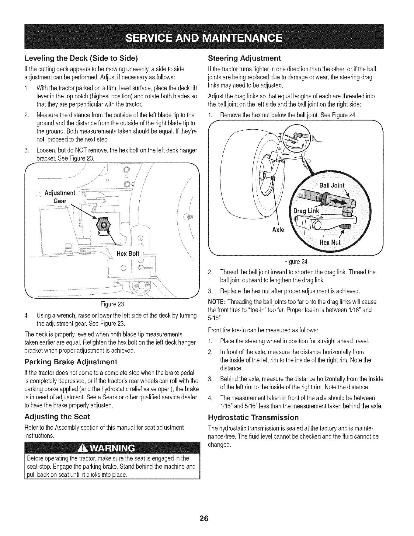
Steering Adjustment
Ifthe tractorturnstighterinonedirectionthanthe other,or if the ball
jointsarebeingreplaceddueto damageor wear,the steeringdrag
linksmayneedto beadjusted.
Adjustthe drag links so thatequallengthsof each arethreadedinto
the ball jointon the left sideand the balljointon the rightside:
1. Removethe hexnut belowthe balljoint.SeeFigure24.
Figure24
2. Threadthe balljointinwardto shortenthe draglink.Threadthe
balljoint outwardto lengthenthedrag link.
3. Replacethe hexnut afterproperadjustmentis achieved.
NOTE: Threadingthe balljointstoofar ontothe draglinkswillcause
the front tires to "toe-in"toofar. Propertoe-in is between1/16"and
5/16".
Fronttiretoe-incan be measuredas follows:
.
2.
Placethe steeringwheelinpositionfor straightaheadtravel.
Infront of the axle, measurethe distancehorizontallyfrom
the insideof the left rimto the insideof the right rim.Notethe
distance.
3. Behindthe axle,measurethe distancehorizontallyfrom the inside
of the left rimto the insideof the rightrim. Notethe distance.
4. The measurementtakenin frontof the axle shouldbebetween
1/16"and5/16"lessthanthe measurementtakenbehindthe axle.
Hydrostatic Transmission
The hydrostatictransmissionis sealedat thefactory andis mainte-
nance-free.The fluidlevelcannotbecheckedandthe fluidcannotbe
changed.
26
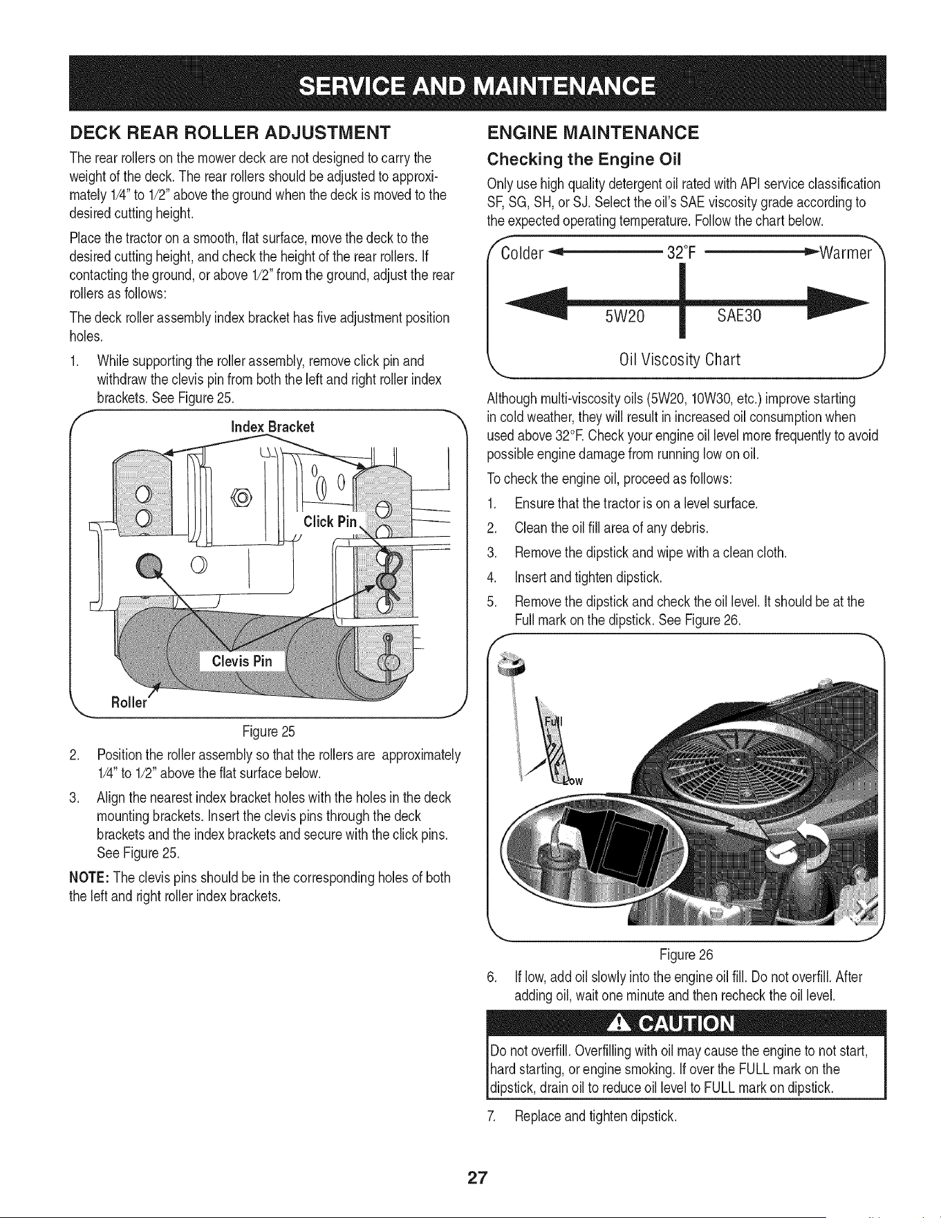
DECK REAR ROLLER ADJUSTMENT
The rear rollerson the mowerdeckarenot designedto carrythe
weightof the deck.The rearrollersshouldbe adjustedto approxi-
mately1/4"to 1/2"abovethe groundwhenthe deckis movedto the
desiredcuttingheight.
Placethetractoron a smooth,fiat surface,movethe deckto the
desiredcuttingheight,and checkthe heightof the rear rollers.If
contactingthe ground,or above 1/2"fromthe ground,adjust the rear
rollersas follows:
Thedeck rollerassemblyindexbrackethasfive adjustmentposition
holes.
f
Whilesupportingthe rollerassembly,removeclick pin and
withdrawtheclevis pinfromboththe leftandright rollerindex
brackets.SeeFigure25.
Index Bracket
Roller
J
Figure25
2. Positionthe rollerassemblyso thatthe rollersare approximately
1/4"to 1/2"abovetheflat surfacebelow.
3. Align thenearestindexbracketholeswiththe holesinthe deck
mountingbrackets.Insertthe clevispinsthroughthe deck
bracketsandthe indexbracketsand securewiththe click pins.
SeeFigure25.
NOTE:The clevispinsshouldbe in the correspondingholesof both
the left and rightrollerindexbrackets.
ENGINE MAINTENANCE
Checking the Engine Oil
Onlyusehighqualitydetergentoil ratedwith API serviceclassification
SF,SG, SH, or SJ. Selectthe oil'sSAE viscositygrade accordingto
the expectedoperatingtemperature.Followthe chartbelow.
"Colder _'_ 32°F ="-Warmer_
Oil Viscosity Chart
Althoughmulti-viscosityoils (5W20,10W30,etc.) improvestarting
incoldweather,they will resultinincreasedoilconsumptionwhen
usedabove32°E Checkyourengineoil levelmorefrequentlyto avoid
possibleenginedamagefromrunninglow on oil.
Tocheckthe engineoil, proceedas follows:
1. Ensurethat the tractoris on a levelsurface.
2. Cleanthe oilfill area of any debris.
3. Removethe dipstickandwipewith a cleancloth.
4. Insertandtightendipstick.
5. Removethe dipstickandcheckthe oillevel.It shouldbeat the
Fullmarkon the dipstick.SeeFigure26.
Figure26
Iflow,addoilslowlyintotheengineoil fill. Donot overfill.After
addingoil, wait one minuteand then recheckthe oillevel.
Do notoverfill.Overfillingwithoilmaycausethe engineto not start,
hardstarting,or enginesmoking.Ifoverthe FULLmarkonthe
dipstick,drain oil to reduceoil levelto FULLmarkon dipstick.
7. Replaceand tightendipstick.
27
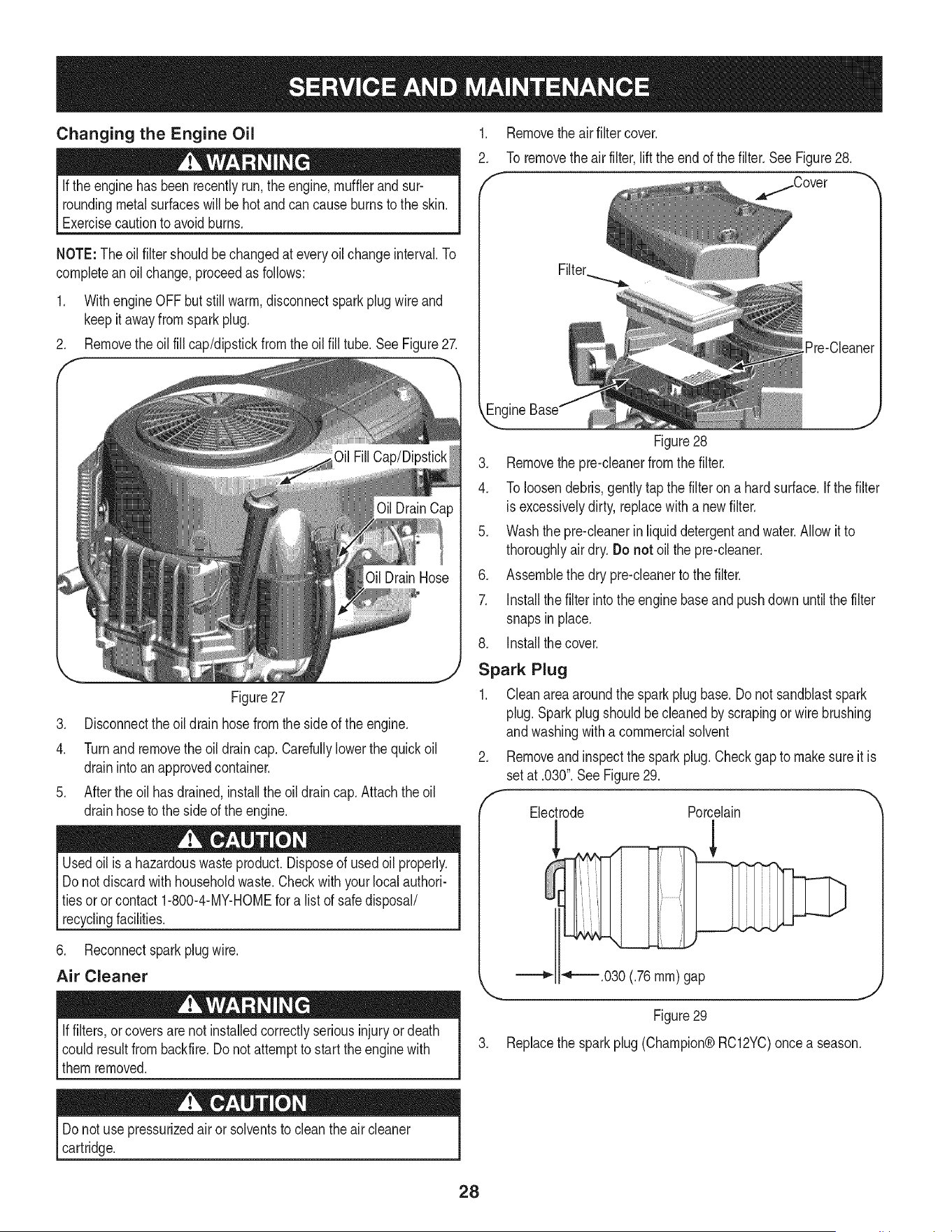
Changing the Engine Oil
Ifthe engine hasbeenrecentlyrun,the engine,mufflerand sur-
roundingmetalsurfaceswill be hotandcan causeburnsto the skin.
Exercisecautionto avoidburns.
,
2.
Removethe air filter cover.
To removethe airfilter,lift the endof thefilter.SeeFigure28.
/Cover
NOTE:The oilfiltershouldbe changedat everyoilchangeinterval.To
completeanoil change,proceedas follows:
1. Withengine OFF butstillwarm,disconnectspark plugwire and
keepit awayfromsparkplug.
2. Removethe oil fill cap/dipstickfromthe oilfill tube.SeeFigure27.
Figure27
[Pre-Cleaner
3. Disconnectthe oildrain hosefromthe sideof theengine.
4. Turnand removethe oildraincap.Carefullylowerthe quick oil
drainintoan approvedcontainer.
5. Afterthe oil has drained,installthe oildraincap.Attachtheoil
drainhoseto the sideof the engine.
Usedoil is a hazardouswasteproduct.Disposeof usedoil properly.
Do notdiscardwithhouseholdwaste.Checkwithyour localauthori-
tiesoror contact1-800-4-MY-HOMEfora list of safedisposal/
recyclingfacilities.
6. Reconnectspark plugwire.
Air Cleaner
Iffilters,orcoversare not installedcorrectlyseriousinjuryor death
couldresultfrom backfire.Do notattemptto start theenginewith
themremoved.
Figure28
3. Removethe pre-cleanerfrom the filter.
4. To loosendebris,gentlytapthe filteron a hardsurface.If thefilter
is excessivelydirty,replacewith a newfilter.
5. Washthe pre-cleanerinliquiddetergentandwater.Allowit to
thoroughlyair dry.Do not oil the pre-cleaner.
6. Assemblethe dry pre-cleanerto the filter.
7. Installthe filterintothe enginebaseand pushdown untilthe filter
snapsin place.
8. Installthe cover.
Spark Plug
1. Cleanarea aroundthe sparkplugbase.Donot sandblastspark
plug. Sparkplugshouldbe cleanedby scrapingor wirebrushing
andwashingwitha commercialsolvent
Removeandinspectthe sparkplug.Checkgapto makesureit is
setat .030".SeeFigure29.
Electrode Porcelain
_ _'_.030 (.76 ram) gap
Figure 29
3. Replace the spark plug (Champion® RC12YC)once a season.
Do notuse pressurizedair or solventsto cleanthe aircleaner
cartridge.
28
Fuel Filter Muffler
Gasolineanditsvaporsareextremelyflammableand explosive.Fire
or explosioncan cause severeburnsor death.
• Keepgasolineawayfrom sparks,open flames,pilotlights,heat,
andotherignitionsources.
• Checkfuellines,tank,cap, and fittingsfrequentlyfor cracks
orleaks.Replaceif necessary.Seea Searsor other qualified
servicedealerto replacefuel line.
• Beforereplacingthe fuel filter,drain the fueltank or closethe fuel
shut-offvalve.
• Replacementparts mustbethe sameandinstalledinthe same
positionas the originalparts.
• If fuelspills,waituntil it evaporatesbeforestartingengine.
To Drainthe Fuel:
1. Locatethefuel filter,whichis routedon the left sideof theengine
betweenthe fuel tankandthe carburetor,andmaybeattachedto
the enginewith a tie strap.
2. Cut the tie strap,if present,thenpinchthe in-line clampon the
fuelfilter with a pair of pliers.
3. Slide theclampupthe fuel line.
4. Pull thefuel linefree fromthe filterandplacethe open end of the
lineintoan approvedcontainerto drainthe fuel.
To Replacethe FuelFilter:
1. Beforereplacingthe fuel filter,drain the fueltank or closethe fuel
shut-offvalve.Otherwise,fuel can leakout andcausea fire or
explosion.
2. Use pliersto squeezetabs on theclamps,then slidethe clamps
awayfromthefuel filter.Twistand pull thefuel linesoff of the fuel
filter.See Figure30.
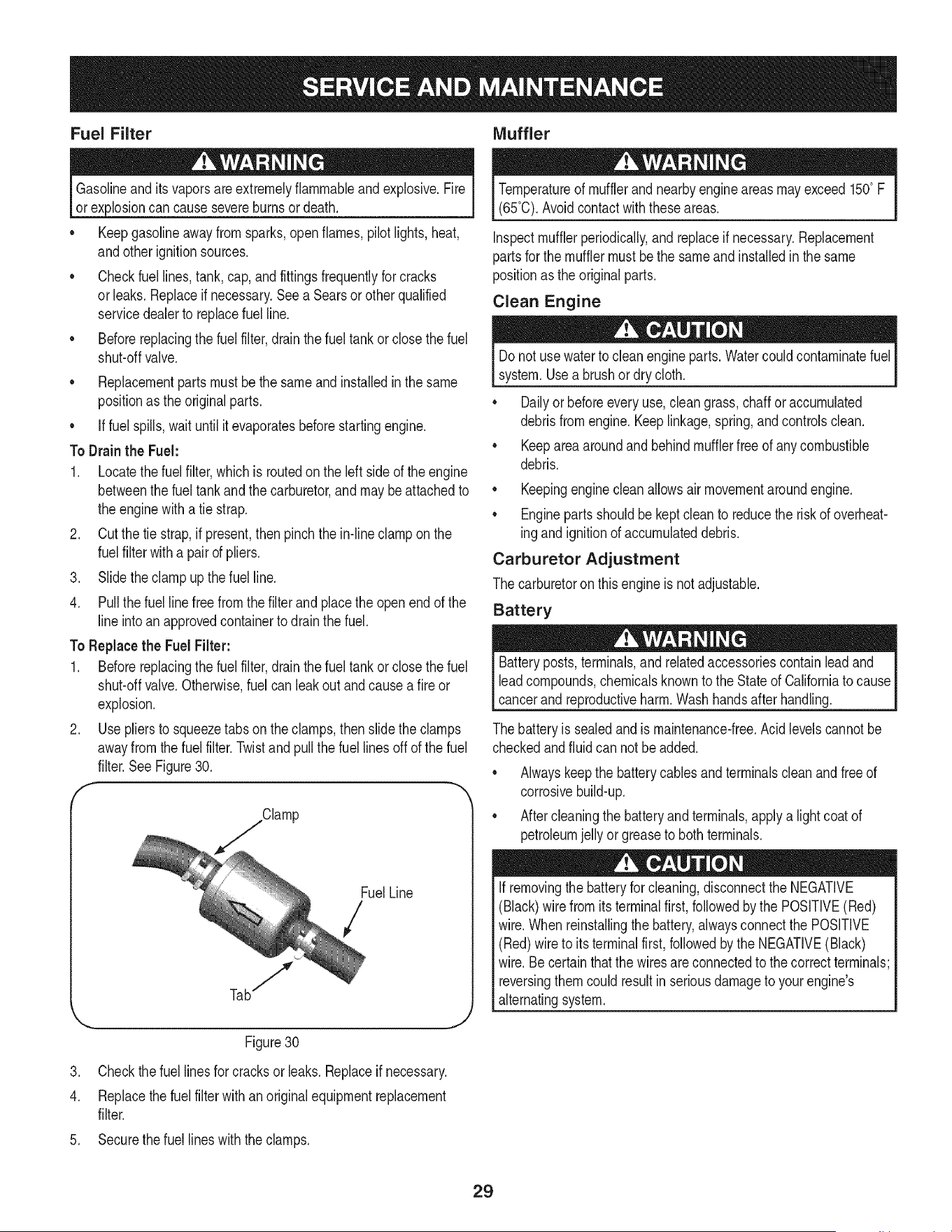
f --,
Clamp
FuelLine
/
Figure30
3. Checkthefuel linesfor cracksor leaks.Replaceif necessary.
4. Replacethefuel filterwithanoriginalequipmentreplacement
filter.
5. Securethe fuel lineswiththe clamps.
Temperatureof mufflerand nearbyengineareasmayexceed150° F
(65°0).Avoidcontactwiththeseareas.
Inspectmufflerperiodically,andreplaceif necessary.Replacement
partsfor the mufflermustbethe sameandinstalledin the same
positionas the originalparts.
Clean Engine
Donot usewaterto cleanengine parts.Watercouldcontaminatefuel
system.Usea brushor dry cloth.
Dailyor beforeeveryuse,cleangrass,chaff or accumulated
debrisfrom engine.Keeplinkage,spring,andcontrolsclean.
Keepareaaroundand behindmufflerfree of anycombustible
debris.
Keepingenginecleanallowsair movementaroundengine.
• Engineparts shouldbekeptcleanto reducethe riskof overheat-
ingandignitionof accumulateddebris.
Carburetor Adjustment
The carburetoron this engineis notadjustable.
Battery
Batteryposts,terminals,and relatedaccessoriescontainleadand
leadcompounds,chemicalsknownto the Stateof Californiato cause
cancerand reproductiveharm.Wash handsafter handling.
The batteryis sealedandis maintenance-free.Acidlevelscannot be
checkedandfluid can notbe added.
Alwayskeepthe batterycablesand terminalscleanandfree of
corrosivebuild-up.
Aftercleaningthe batteryand terminals,applya lightcoatof
petroleumjelly or greaseto bothterminals.
Ifremovingthe batteryforcleaning,disconnectthe NEGATIVE
(Black)wire from its terminalfirst, followedby the POSITIVE(Red)
wire.Whenreinstallingthe battery,alwaysconnectthe POSITIVE
(Red)wire to its terminalfirst, followedbythe NEGATIVE(Black)
wire.Becertainthatthe wires are connectedto the correctterminals;
reversingthemcouldresult in seriousdamageto yourengine's
alternatingsystem.
29
Neverstoregardentractorwith fuel intankindoorsor in poorly
ventilatedareaswherefuel fumesmay reachan openflame,spark,
or pilot lightas ona furnace,water heater,clothesdryer,or gas
appliance.
PREPARING THE ENGINE
IMPORTANT:Fuelleft in the fueltank duringwarm weatherdeterio-
ratesandwill cause seriousstartingproblems.
Topreventgum depositsfromforminginsidetheengine'scarburetor
andcausingpossiblemalfunctionof the engine,the fuel systemmust
beeithercompletelyemptied,or thegasolinemustbe treatedwith a
stabilizerto preventdeterioration.
If usinga fuel stabilizer:
a. Readthe productmanufacturer'sinstructionsand recom-
mendations.
b. Add to clean,freshgasolinethe correctamountof stabilizer
for thecapacityof the fuel system.
c. Fill thefuel tankwithtreatedfueland run theenginefor 2-3
minutesto get stabilizedfuel intothe carburetor.
If emptyingthefuel system:
a. Do notdrain fuel whentheengineis hot. Allowtheengine
adequatetimeto cool. Drainfuel intoan approvedcontainer
outdoors,awayfromopenflame.
b. Drainany largevolumeof fuelfromthe tank by disconnect-
ingthe fuel linefromthe in-line fuelfilterneartheengine.
SeeToDrainthe Fuelonpage28.
Gasolineis extremelyflammableand can beexplosiveundercertain
conditions.Draingasolinebeforestoringtheequipmentfor extended
periods.Drainfuelonly intoan approvedcontaineroutdoors,away
fromanopenflame.Allowengine to cool.Extinguishcigarettes,
cigars,pipes,and other sourcesof ignitionpriorto drainingfuel.
Storegasolinein an approvedcontainerin safe location.
c. Reconnectthe fuelline and run theengineuntilit startsto
falter,then usethe choketo keepthe engine runninguntilall
fuelin the carburetorhasbeen exhausted.
d. Disconnectthe fuel line and drainany remaininggasoline
fromthe system.
PREPARING THE GARDEN TRACTOR
• Cleanand lubricatetractorthoroughlyas describedin the
lubricationinstructions.
• Do notuse a pressurewasheror gardenhoseto cleanyour
unit.
• Storemowerin a dry, cleanarea.Do not storenext to
corrosivematerials,suchas fertilizer.
Gasolineis a toxicsubstance.Disposeof gasolineproperly.Contact
yourlocal authoritiesfor approveddisposalmethods.
Removethespark plug and pour one(1)ounceof engine oil through
the sparkplug hole intothe cylinder.Crankthe engineseveraltimesto
distributetheoil. Replacethe sparkplug.
30
Beforeperforminganytypeof maintenance/service,disengageall
controlsandstoptheengine.Waituntilallmovingpartshavecometo
a completestop.Disconnectsparkplugwireandgroundit againstthe
engineto preventunintendedstarting.Alwayswearsafetyglassesduring
operationor whileperforminganyadjustmentsorrepairs.
Thissectionaddresses minorserviceissues.To locate the nearestSears Service Centeror to scheduleservice,simplycontactSears
at 1-800-4-MY-HOME®.
1. PTO/BladeEngageknobengaged.
2. Parkingbrakenotengaged.
3. Sparkplugwire disconnected.
4. Throttlecontrollevernot incorrectstarting
position.
5. Fueltankempty,or stalefuel.
Enginefailsto start
6. BIockedfuel line.
7. Faultysparkplug.
8. Engineflooded.
9. Fuse(s)blown.
1. Tractorrunningwith Chokeactivated.
2. Sparkplugwiresloose.
3. Blockedfuel lineor stalefuel.
4. Ventingas cap plugged.
5. Wateror dirt in fuel system.
Dirtyair cleaner.
Enginerunserratically
6. 6.
Engineoverheats 1. Engineoil levellow 1.
2. Air flow restricted 2.
Enginehesitatesat high RPMs 1. Sparkpluggap settooclose 1.
Engineidlespoorly 1. Fouledspark plug 1.
2. Dirtyair cleaner 2.
Excessivevibration 1. Cuttingbladeslooseor unbalanced 1.
2. Damaged,dull,or bentcuttingblade 2.
1. Placeknobin disengaged(OFF)position.
2. Engageparkingbrake.
3. Connectwireto sparkplug.
4. PlaceThrottleleverto FASTposition.
5. Filltankwithclean,fresh(lessthan 30 days old) gas.
6. Replacefuel line.See a Searsorotherqualified
servicedealer.Replacefuel filter.Seethe Service
andMaintenancesection.
7. Clean,adjustgap or replaceplug.
8. Crankenginewith throttlein FASTposition.
9. Replacefuse.
1. Checkthat the electricchokeis working.Seea
Searsor otherqualifiedservicedealer.
2. Connectand tightenspark plugwires.
3. Replacefuel line.See a Searsorotherqualified
servicedealer.Filltankwithclean,freshgasoline
andreplacefuel filter.Seethe Serviceand Mainte-
nancesection.
4. Clearvent or replacecap if damaged.
5. Drainfueltank. Refillwith clean,fresh gasoline.See
theServiceand Maintenancesection.
Cleanor replaceair cleanerpaperelementor clean
foampre-cleaner.
Fillenginewith properamountand type of oil.
Cleangrassclippingsanddebrisfrom aroundthe
engine'scoolingfins and blowerhousing.
Removesparkplugandadjustgap.
Replacesparkplugandadjustgap.
Cleanor replaceair cleanerelementand/orclean
pre-cleaner.
Tightenbladeandspindle.Balanceblade.
Replaceblade.
31
Mowerwill not mulchgrass
Unevencut
1. Enginespeedtoo low.
2. Wetgrass.
3. Excessivelyhigh grass.
4. Dullblade.
1. Decknot leveledproperly.
2. Dullblade.
3. Uneventire pressure.
1. PlaceThrottlecontrolin FAST(rabbit)position.
2. Do notmulchwhengrassis wet.
3. Mowonce at a highcuttingheight,then mowagain
at desiredheightor makea narrowercuttingswath.
4. Sharpenor replaceblade.
1. Performside-to-sidedeck adjustment.
2. Sharpenor replaceblade.
3. Checktire pressureinallfour tires.
NEED MORE HELP?
Find this and air your other product manua{s online,
Get answers from our team of home experts.
Get a persona[ized maintenance p[an for your home,
Find information and tools to help with home projects.
b_e_#]_l te yew i_- Sea_s
32
Congratulationson makinga smartpurchase.YournewCraftsman@
productis designedand manufacturedfor yearsof dependableopera-
tion.But likeall products,it mayrequirerepairfromtimeto time.That's
whenhavinga RepairProtectionAgreementcansave youmoneyand
aggravation.
Here'swhatthe RepairProtectionAgreement*includes:
* Expert service byour 10,000professionalrepairspecialists
o Unlimitedserviceand no chargefor partsand laboron all
coveredrepairs
o Product replacementup to $1500if yourcoveredproductcan't be
fixed
• Discountof 10%from regularprice of serviceand relatedinstalled
partsnotcoveredby theagreement;also, 10%off regularpriceof
preventivemaintenancecheck
• Fast help by phone- we call it RapidResolution- phonesupport
froma Searsrepresentative.Thinkof usas a "talkingowner's
manual."
Onceyou purchasethe Agreement,a simplephonecall is all thatit
takesfor youto scheduleservice.Youcan call anytimedayor night,or
schedulea serviceappointmentonline.
The RepairProtectionAgreementis a risk-freepurchase.If youcancel
for any reasonduringthe productwarrantyperiod,wewill providea full
refund.Or,a proratedrefundanytimeafterthe productwarrantyperiod
expires.Purchaseyour RepairProtectionAgreementtoday!
Somelimitationsand exclusionsapply. For pricesand additional
informationin the U.S.A. call 1-800-827-6655.
*Coverage in Canadavaries on some items. Forfull details call
Sears Canadaat 1-800-361-6665.
Sears Installation Service
ForSearsprofessionalinstallationof homeappliances,garagedoor
openers,waterheaters,and othermajorhomeitems,in the U.S.A.or
Canadacall 1-800-4-MY-HOME®.
33
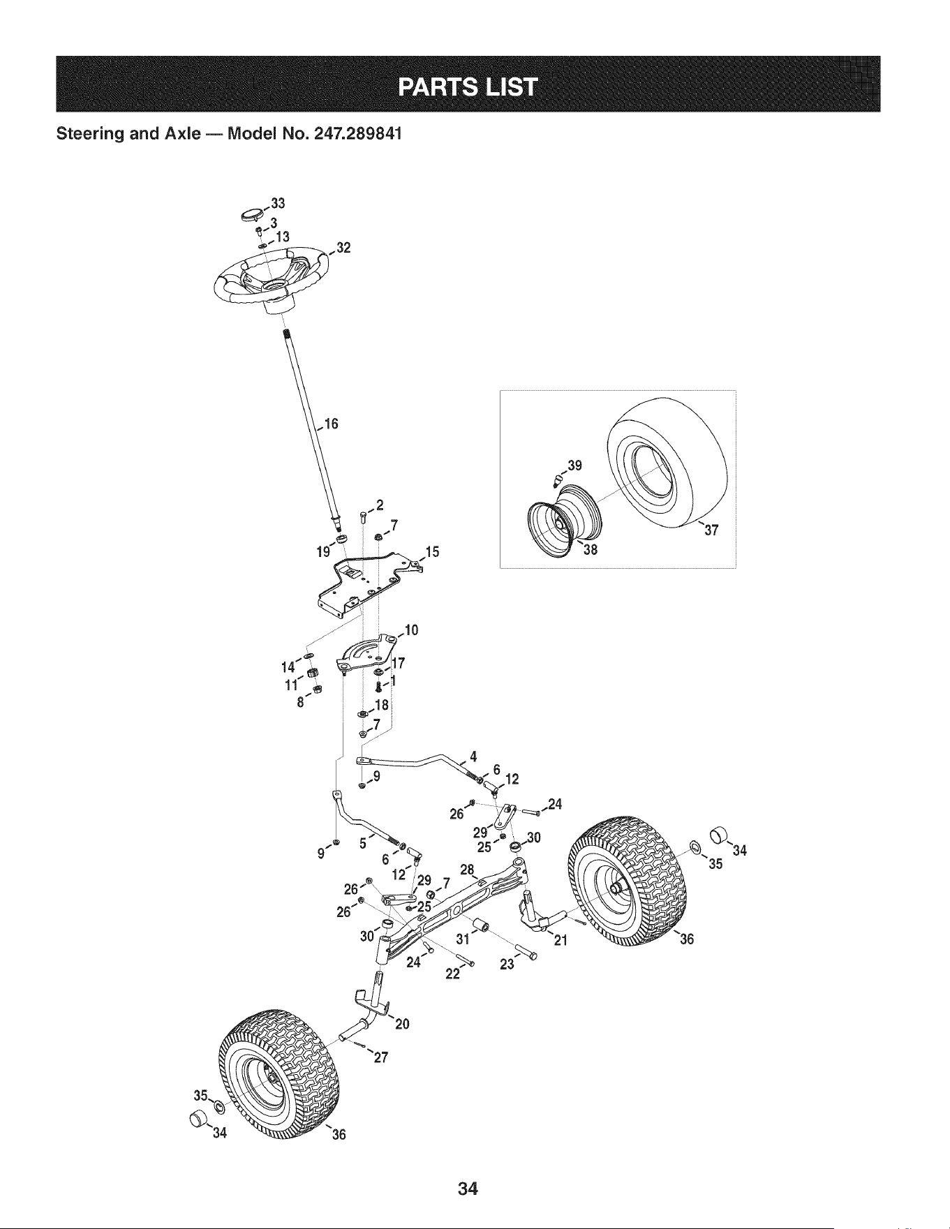
Steering and Axle B IViodel No. 247.289841
.13
..32
39
37
35.
34

Steering and Axle B IViodel No. 247.289841
710-04095 HexHeadScrew,3/8-16:1.00 938-04041-0637 LHAxle Assembly
2 710-0514 HexHeadScrew,3/8-16:1.00 22 710-0395 HexHeadScrew,5/16-18:2.25
3 710-0643 HexHeadScrew,5/16-18:1.00 23 710-0859 HexHeadScrew,3/8-16:2.50
4 711-04998 LH DragLink 24 710-3180 HexHeadScrew,5/16-18:1.75
5 711-04999 RHDragLink 25 912-0214 HexlockNut,3/8-24
6 912-0240 JamNut,7/16-20 26 712-04063 FlangelockNut,5/16-18
7 712-04065 FlangelockNut,3/8-16 27 714-0162 CotterPin,5/32:1.25
8 712-0459 FlangelockNut,7/16-20 28 719-04413A PivotBarAxle
9 712-3004A FlangelockNut,5/16-18 29 748-04065-0637 SteeringBlock
10 717-1550F SteeringGear 30 748-04068 Spacer,.71ID x .125ODx .56LG
11 717-1554 SteeringPinionGear 31 750-05280 Spacer,.385x 1.00x 1.5075
12 923-0448A BallJoint,7/16-20 32 631-04415 SteeringWheel
13 936-3004 FlatWasher,.406x .875x .105 33 731-06825 SteeringWheelCap
14 736-3084 FlatWasher,.51x 1.12x .06 34 731-05674 BumperCap
15 783-06043-0637 SteeringSupportBracket 35 736-04228A FlatWasher,.7811Dx 1.5900D
16 738-04263 SteeringShaft,.625OD x24.25 LG 36 634-04466-0961 WheelAssembly
17 738-04363 ShoulderSpacer,.385x 1.25x .3025 37 734-1727 Tire
18 738-04364B Spacer,.38x 1.375 38 934-04082-4042 RimAssembly
19 741-04237B HexFlangeBearing5/8 PM i39 934-0255 TubelessAirValve
20 938-04040-0637 RHAxle Assembly
35
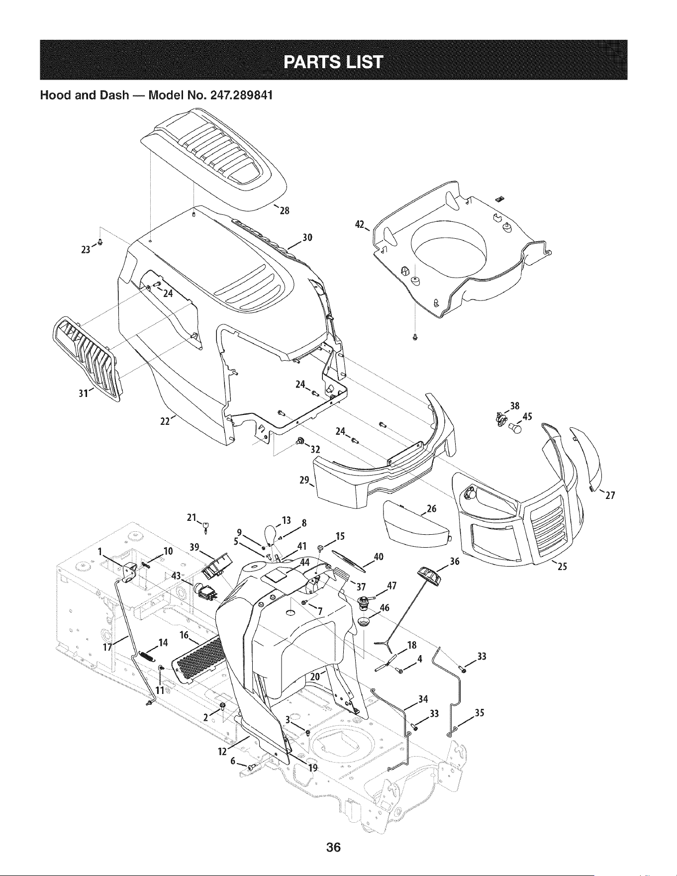
Hood and Dash B IViodel No. 247.289841
21
8
36

Hood and Dash B IViodel No. 247.289841
631-04353P DashLever 731-07458 RHLens
2 710-04484 TaptiteScrew,LockWasher,5/16-18:.750 i27 731-07459 LH Lens
3 710-0599 TaptiteScrew,LockWasher,1/4-20:0.500 i28 931-07461 HoodScoop
4 710-0895 Hi-LoScrew,LockWasher,1/4-15:0.750 i29 731-07467 LowerGrill
5 710-1017 Screw,1/4-14:0.625 i30 731-07711A LH HoodScoop
6 710-1611B TaptiteScrew,5/16-18:0.750 i31 731-07712A RH HoodScoop
7 710-1652 TaptiteScrew,1/4-20x .625 i32 738-04091A ShoulderScrew,.43x .29:TT:5/16-18
8 710-3217 MachineScrew,#8-32:0.375 i33 710-0642 TaptiteScrew,1/4-20:0.750
9 712-0142 HexNut,#8-32:GRA i34 747-05049 RHTankSupportRod
10 714-04040 Bow-tieCotterPin i35 747-05050 LHTankSupportRod
11 726-3046 RatchetClip:.250DIA i36 951-12179 FuelCap
12 731-07456 Dash i37 951-11650 FuelTank
13 731-07550 ControlKnob i38 925-1649 LampSocket
14 732-04580 ExtensionSpring,.500DIAx 2.733LG i39 725-04992 KeySwitchModule
15 735-0271A Bumper i40 735-04170 FuelTank Gasket
16 735-04076 AccessoryNet i41 946-1100 ThrottleControl
17 747-05280 ControlRodLatch i42 731-07495 P-StylePlen
18 747-1196 LeverRod i43 725-04258 PTOSwitch
19 783-04285F-0637RHDashSupportPlate J44 925-04036C HourMeter
20 783-04323F-0637LH DashSupportPlate i45 925-0963 MiniatureLamp,12V
21 625-04124 Key(Set of 2) i46 735-04081 RubberGrommet
22 683-04618-0691 HoodAssembly i47 751-12118 FuelRolloverValve
23 710-04187 Hi-loScrew,LockWasher,1/4-15:0.50 -- 777X44365 RHReflectorLabel(NotShown)
24 710-05108 Screw,Lock Washer,1/4DIA:.750 -- 777X44366 LH ReflectorLabel(Not Shown)
25 931-07457 Grill
37
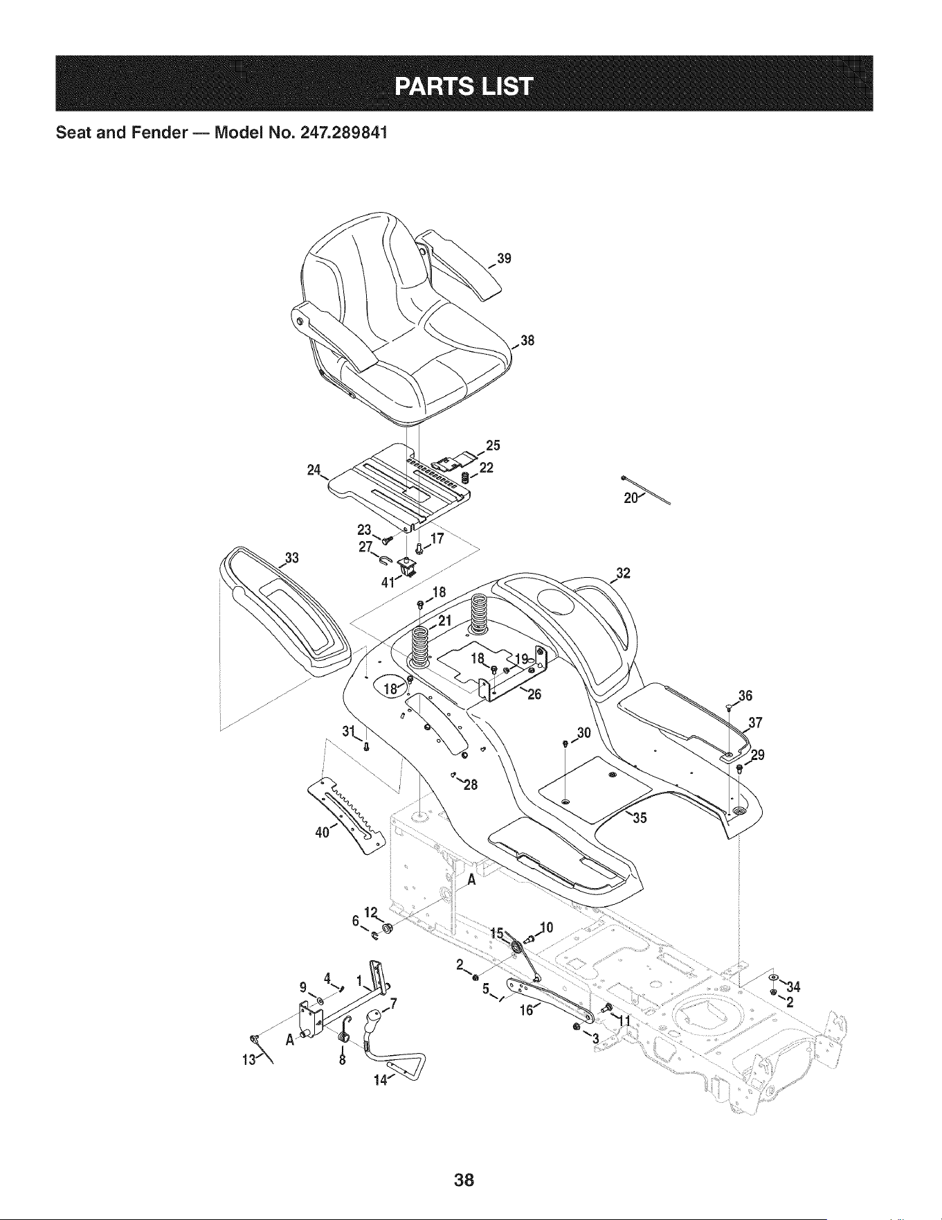
Seat and Fender B IViodel No. 247.289841
39
33
23
2\
25
32
38

Seat and Fender B IViodel No. 247.289841
683-04301-0637 Lift ShaftAssembly 732-04563 CompressionSpring,.68x 1.065x .055
2 712-04063 FlangelockNut,5/16-18 i23 938-0296 ShoulderScrew,.437x .268:5/16-18
3 712-04065 FlangelockNut,3/8-16 i24 783-06049-0691 Seat MountingBracket
4 914-0104 CotterPin,.072DIA.x 1.13LG i25 783-06050 SeatAdjustmentLever
5 714-04040 Bow-TieCotterPin i26 783-06088-0691 Seat PivotBracket
6 716-0106A E-Ring,.625DIA.SHAFT i27 783-06448 SwitchRetainerClip
7 720-04150 HandleGrip i28 710-04187 Hi-LoScrew,LockWasher,1/4-15:0.50
8 732-0874 TorsionSpring i29 710-0451 CarriageBolt,5/16-18:.750
9 736-0105 SpringWasher,.401x .870x .063 i30 710-0599 TaptiteScrew,LockWasher,1/4-20:0.500
10 738-0138A ShoulderScrew, .437x .470:5/16-18 i31 710-0895 Hi-LoScrew,LockWasher,1/4-15:0.750
11 938-0380 ShoulderBolt,.500x.270:3/8-16 i32 731-05837 LH FenderCover
12 941-0225 HexFlangeBearing i33 731-06754 RH FenderCover
13 746-0968 LiftCable,16.16LG i34 736-3078 FlatWasher,.344x 1.00x .063 HDN
14 747-04962A Lift Handle i35 783-06118-0691 Fender
15 756-04331 PulleyRollerCable i36 726-3046 RatchetClip
16 783-05546A-0637Lift Arm i37 735-04137 LH FootPad
17 710-04482 Hex HeadFlange,3/8-16:.875 -- 735-04139 RHFootPad
18 710-04484 TaptiteScrew,LockWasher,5/16-18:.750 38 757-04128 Seat
19 712-3004A FlangelockNut,5/16-18 i39 957-04134 Armrests
20 i725-0157 CableTie, 3/16x.O5x 7.4 i40 783-06181-0637 LiftBracket
21 732-04849 CompressionSpring,1.71x 3.735x .238 i41 925-05013 Seat Switch
39
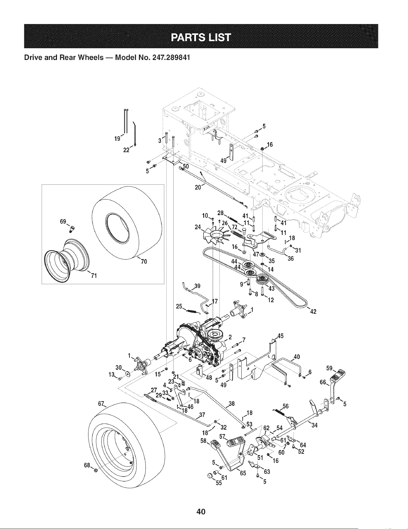
Drive and Rear Wheels B Model No. 247.289841
69
7O
7
i
11 42
49
18
58,
5_
61
55
4O

Drive and Rear Wheels B Model No. 247.289841
918-04317 WheelAssemblyHub 747-05124 BrakeRod
2 918-04917 Transmission i38 747-05125A ControlRod
3 710-0189 HexScrew,5/16-18:3.00 i39 747-05130 DisengageRod
4 710-0227 Screw,#8-18:0.500 i40 747-05181 BeltKeeper,5/16
5 710-04484 TaptiteScrew,5/16-18:.750 i41 750-04456 Spacer,260 x .372x 1.420LG
6 710-0599 TaptiteScrew,1/4-20:0.500 i42 954-04244A V Belt,4Lx 77.0
7 710-0909A TaptiteScrew,5/16-18:1.750 i43 756-04224 Fiat IdlerPulley,2.75OD
8 710-1007 TaptiteSeresScrew,3/8-16:1.500 i44 756-04325 V IdlerPulley,3.06
9 710-1008 TaptiteSeresScrew,3/8-16:1.875 i45 783-05443A-0637TorqueBracket
10 710-1189 Screw,#12-24:0.625 i46 783-05841 SwitchBracket
11 710-1325 TaptiteScrew,1/4-20:1.625 i47 783-06027A Center IdlerBracket
12 710-3011 HexScrew,3/8-16:2.25 i48 783-06501A-0637DeckBracket
13 710-3119 HexScrew,3/8-16:.750 i49 783-06503 PlateBracket
14 912-0240 JamNut,7/16-20 i50 783-0693A-0637 Axle Bracket
15 712-04063 FlangelockNut,5/16-18 i51 683-04571 PedalBracketAssembly
16 712-04065 FlangelockNut,3/8-16 i52 710-0604A TaptiteScrew,5/16-18:0.625
17 914-0104 CotterPin,.072DIA.x 1.13LG i53 711-05068 ClevisPin,5/16x 3.985
18 914-0111 CotterPin,3/32:1.0 i54 714-04040 Bow-TieCotterPin
19 725-0157 CableTie,3/16x .05x 7.4 i55 726-0214 PushCap
20 725-04791A JumperHarness 56 732-04587 ExtensionSpring,.63 DIAx 4.95LG
21 725-1644 ShortSpringSwitch i57 735-04118A ForwardPedal Pad
22 926-0154 PushMountCableTie 7.5LG i58 735-04135 ReversePedal Pad
23 926-0320 InsulatorNutPlate i59 735-04136 BrakePedal Pad
24 931-1449A BladeFan i60 938-0380 ShoulderBolt,.500x .270:3/8-16
25 732-04528 ExtensionSpring,.50DIAx 5.0 LG i61 741-0495 FlangeBearing,.630 IDx .695ODx .60
26 732-04792 ExtensionSpring,1.00DIAx 4.75 i62 748-04203 CruiseLatch
27 732-0716D ExtensionSpring,.59ODx 4.00 LG 63 783-05914 PedalSupportBracket
28 732-0932 ExtensionSpring,.38DIA x 5.6 i64 783-05940 PedalSupportBracket,5/8
29 732-3118 ExtensionSpring,.375OD x 1.44LG i65 783-06059-0637 DrivePedalBracket
30 936-0227 FlatWasher,.390x 1.500x .134 i66 783-06103A-0637BrakePedalBracket
31 936-0344 FlatWasher,.330x .630x .0635 i67 634-0202A-0961 CompleteWheel
32 936-3008 FlatWasher,.344 x .750x .120 68 712-3050 LugNut,7/16-14
33 736-3010 FlatWasher,.407x .812x .135 i69 934-0255 Air Valve
34 647-04152B BrakeControlAssembly i70 734-04147-0901 Tire
35 738-04420 ShoulderSpacer,1.375x .380x .183 i71 634-04238-4042 RimAssembly
36 747-04957A FootPedalBypassTransmissionRod i72 738-1229A Shldr.Screw,.625x 2.50:1/2-13
41
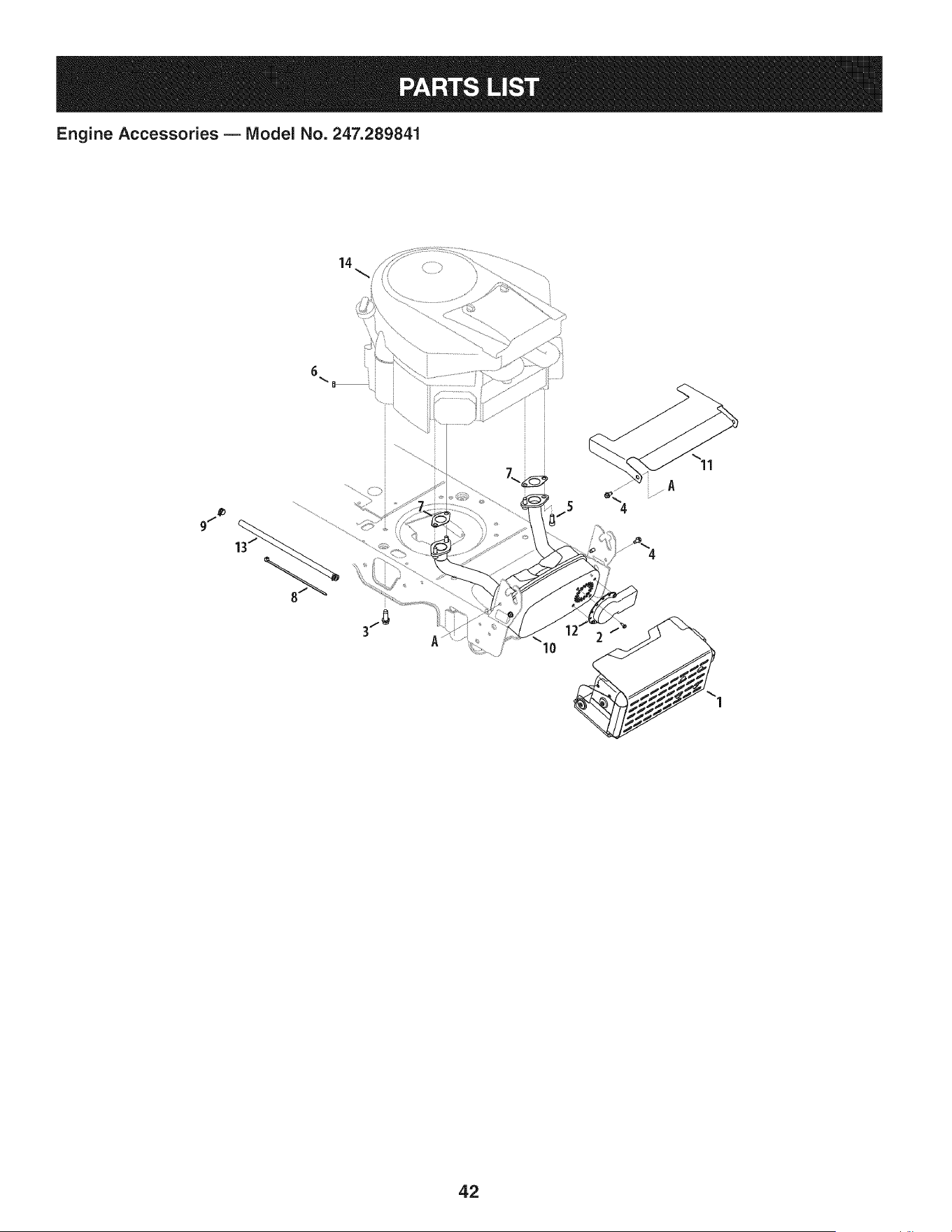
Engine Accessories B IViodel No. 247.289841
14
42

Engine Accessories B IViodel No. 247.289841
683-04549-0637 MulfflerShieldAssembly
2 710-0227 Screw,IndentedWasher,#8-18:0.500
3 710-04683 TaptiteScrew,IndentedWasher,3/8-16:1.000
4 710-0599 TaptiteScrew,IndentedWasher,1/4-20:0.500
5 710-1314A SocketHeadScrew,5/16-18:.750
6 712-0271 SeresNut, 1/4-20
7 721-0460 ExhaustGasket
8 725-0157 CableTie, 3/16x .05x 7.4
9 726-0205 HoseClamp,.490 DIA.
10 751-10542A Muffler
11 783-06378A HeatShield
12 751-0564B MufflerDeflector
13 751-10349 FuelHose
BS-49M877-
14 1047-G5 ReplacementEngine
43
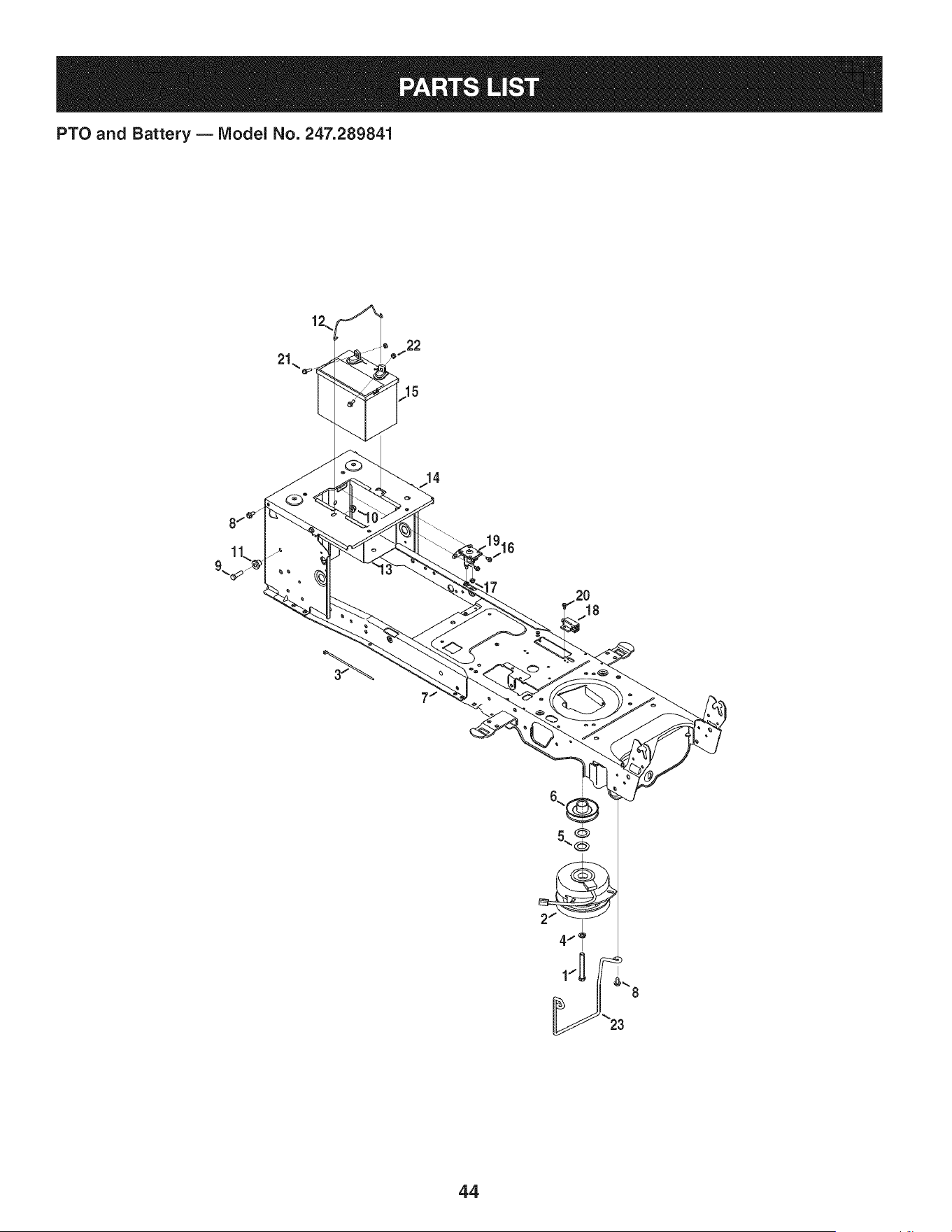
PTO and Battery B IViodel No. 247.289841
22
15
7
18
44

PTO and Battery B Model No. 247.289841
710-04379A HexHeadScrew,7/16-20:3.50
2 917-1774C ElectricPTOClutch
3 725-0157 CableTie,3/16x .05x 7.4
4 936-0171 LockWasher,7/16
5 736-0277 FiatWasher,1.031x 1.620x .095
6 756-0978B ElectricPTOEnginePulley
7 683-04469B-0691 Frame
8 710-04484 TaptiteScrew,indentedWasher,5/16-18:.750
9 710-3005 HexHeadScrew,3/8-16:1.25
10 712-04065 FlangelockNut,3/8-16
11 738-04058 ShoulderSpacer,.38x 1.0x .70
12 747-04121A BatteryHolderRod
13 783-0349-0637 BatteryTray
14 783-06089-0637 SeatFrameBracket
15 i725-05088 Battery
16 i710-0653 TaptiteScrew,1/4-20:0.375
17 712-04064 FlangelockNut,1/4-20
18 725-04363 interlockSwitch
19 i725-04439 Solenoid,12V
20 i738-04237A ShoulderScrew,#10-32:.500
21 710-04666 HexHeadFlange,1/4-20:.75
22 712-0271 SemsNut, 1/4-20
23 747-05195 Belt KeeperRod
NS 925-04093 WireHarnessAssembly
45
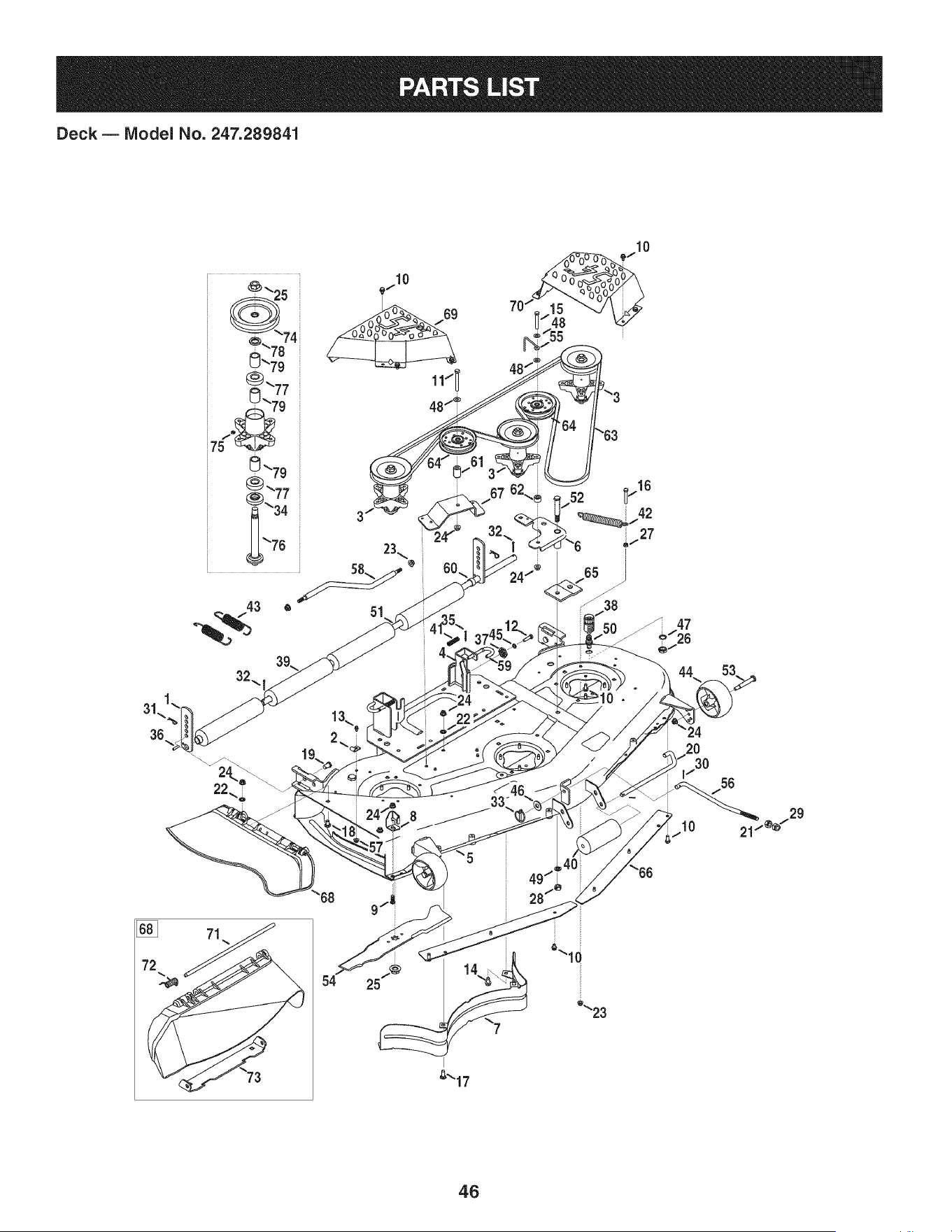
Deck B Model No. 247.289841
51
22
_10 -
10
68
54
9
25
I
_17
_"_23
46

Deck B Model No. 247.289841
12650 HeightAdjustBracket 732-04652 CompressionSpring,.535 ODx 1.751LG
2 96606 RetainerHookBracket i42 732-04692 ExtensionSpring,.85 ODx 5.915LG
3 918-04608A SpindleAssembly i43 732-0934 ExtensionSpring,1.15OD x 5.99 LG
4 683-0254B-4028 DeckHangerBracketAssembly i44 734-04155 DeckWheel
5 983-04585-4028 DeckAssembly i45 936-0119 LockWasher,5/16
6 683-0459-0637 IdlerAssembly i46 936-0179 FiatWasher,.531x 1.25x .100
7 703-2093-0637 InnerBaffle i47 736-0225 LockWasher,5/8
8 703-3279-4028 DeflectorChuteStop i48 936-0300 FlatWasher,.406x .875x .059
9 710-04095 HexScrew,3/8-16:1.00 i49 936-0921 LockWasher, 1/2
10 710-04484 TaptiteScrew,5/16-18:.750 i50 737-04003D DeckWater Nozzle
11 710-0521 HexScrew,3/8-16:3.00 i51 738-0295 Shaft, .750x .47.12
12 710-0528 HexScrew,5/16-18:1.25 i52 738-1229A Shldr.Screw,.625x2.50:1/2-13
13 710-0597 HexScrew,1/4-20:1.00 i53 938-3056 ShoulderBolt,.496x2.50:3/8-16
14 710-0623 TaptiteScrew,3/8-16:0.750 i54 942-0677B Blade
15 710-0859 HexScrew,3/8-16:2.50 i55 747-04938 BeltKeeperRod
16 710-3103 HexScrew,5/16-18:2.00 i56 747-05141A DeckLiftRod
17 710-3168 CarriageBolt,3/8-16:1.00 i57 712-04064 FlangelockNut, 1/4-20
18 710-3178 CarriageBolt,3/8-16:0.75 i58 747-05462 Anti-swayRod
19 911-0332 ClevisPin,.50 DIAx.78 LG 59 747-1116 DeckReleaseHandleRod
20 911-3314 RollerPin, 1/2DIA x 7.31LG i60 950-0212 Spacer,.82 ID x 1.00OD x .53
21 912-0206 HexNut, 1/2-13 i61 750-04597 Spacer,.380x.900x 1.313
22 712-0229 PushNut,3/8 i62 750-0933 Spacer,.385 IDx .88 x .64
23 712-04063 FlangelockNut,5/16-18 i63 954-04083 V Belt
24 712-04065 FlangelockNut,3/8-16 64 756-04129B IdlerPulley,4.25"DIA
25 712-0417A FlangeNut,5/8-18 i65 783-04013A-0637PulleyStabilizerBracket
26 912-0641 HexNut,M16-1.5DIN936 i66 783-04690B-0637DeckSkirt
27 912-3010 HexNut,5/16-18 i67 783-04726-0637 Stationaryldler Bracket
28 712-3022 HexlockNut,Counterlock,1/2-13 i68 631-04070A ChuteAssembly
29 712-3083 HexlockNut, 1/2-13 i69 783-1470A-4028 RHSpindleCover
30 914-0111 CotterPin,3/32:1.0 i70 783-1471-4028 LHSpindleCover
31 914-0145 Click Pin,.092x 1.64LG 71 711-04565 HingePin
32 714-0162 CotterPin,5/32:1.25 i72 732-04372 TorsionSpring,.44 IDx 2.0
33 753-04070 LynchPin,.1875 i73 783-05030 Chute Bracket
34 750-1349A Spacer,.79x 1.82x.55 LG i74 756-04213 DeckPulley
35 914-0470 CotterPin, 1/8x 1.25 i75 937-3000 LubeFitting
36 715-0108 SpringPin, 1/4 DIAx 1.00LG 76 738-1197 SpindleShaft,6.95 LG
37 917-04074 DeckGear i77 941-0919 BallBearing,.787ID x 1.85OD x .551
38 921-04041 WaterNozzleAdaptor i78 748-0160A Spacer,.790ID x 1.25ODx.175
39 731-0335 DeckRoller i79 750-1000 Spacer,.80x 1.10x 1.322LG
40 731-05679 FrontRoller
4.7
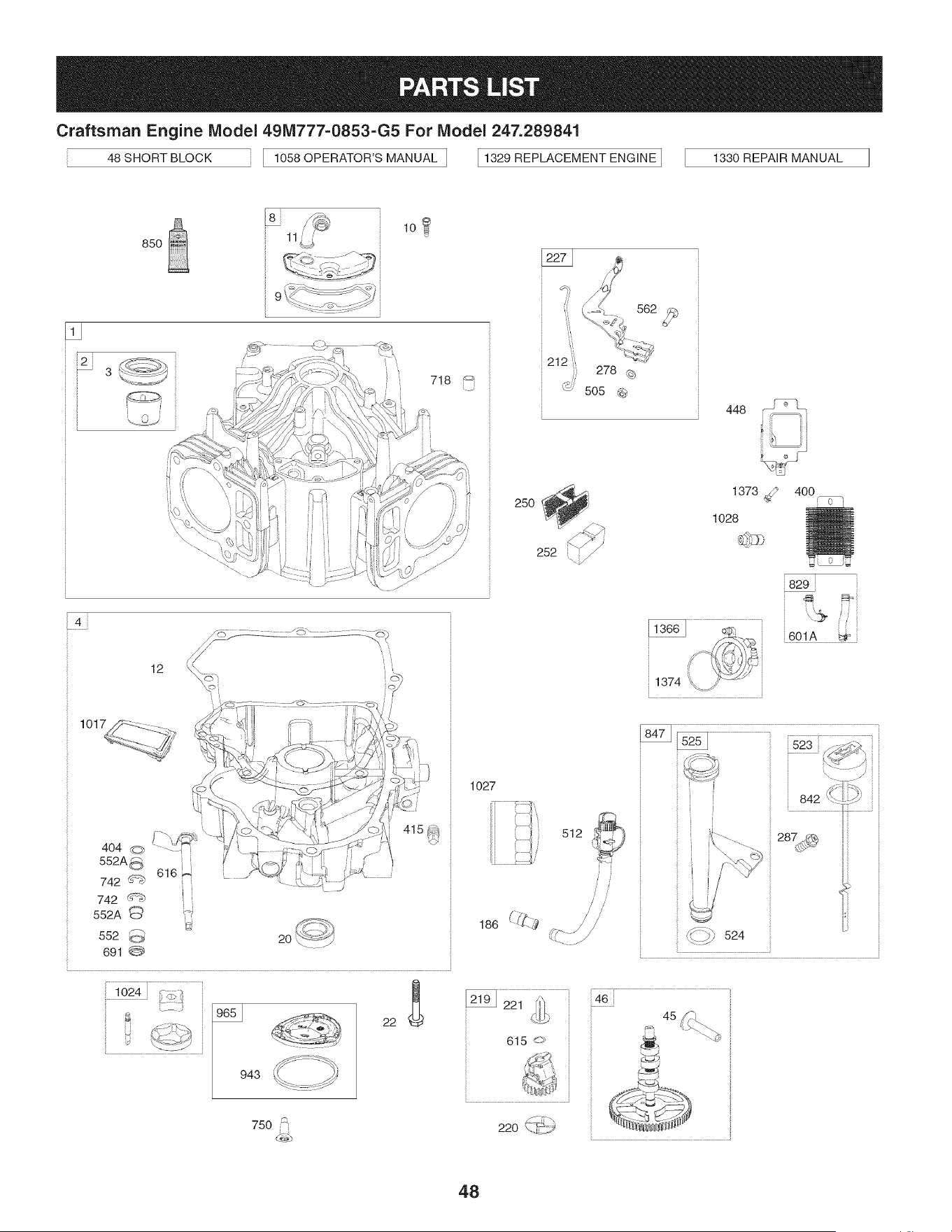
Craftsman Engine Model 491Vi777=0853=G5For Model 247.289841
48 SHORT BLOCK 1058 OPERATOR'S MANUAL ] I 1329 REPLACEMENT ENGINE ] 1330 REPAIR MANUAL
850
3
i i
i i
9 - :L _- :¢
718
250
582,_
212 i,
505 @
252
448
1373_
1028
4OO
o
829
4
12
552
691 @
, 1024 i_/-,>_
ii,
1027
512
J J
/ /
/ //
_::::::b 524
,_-/j
48
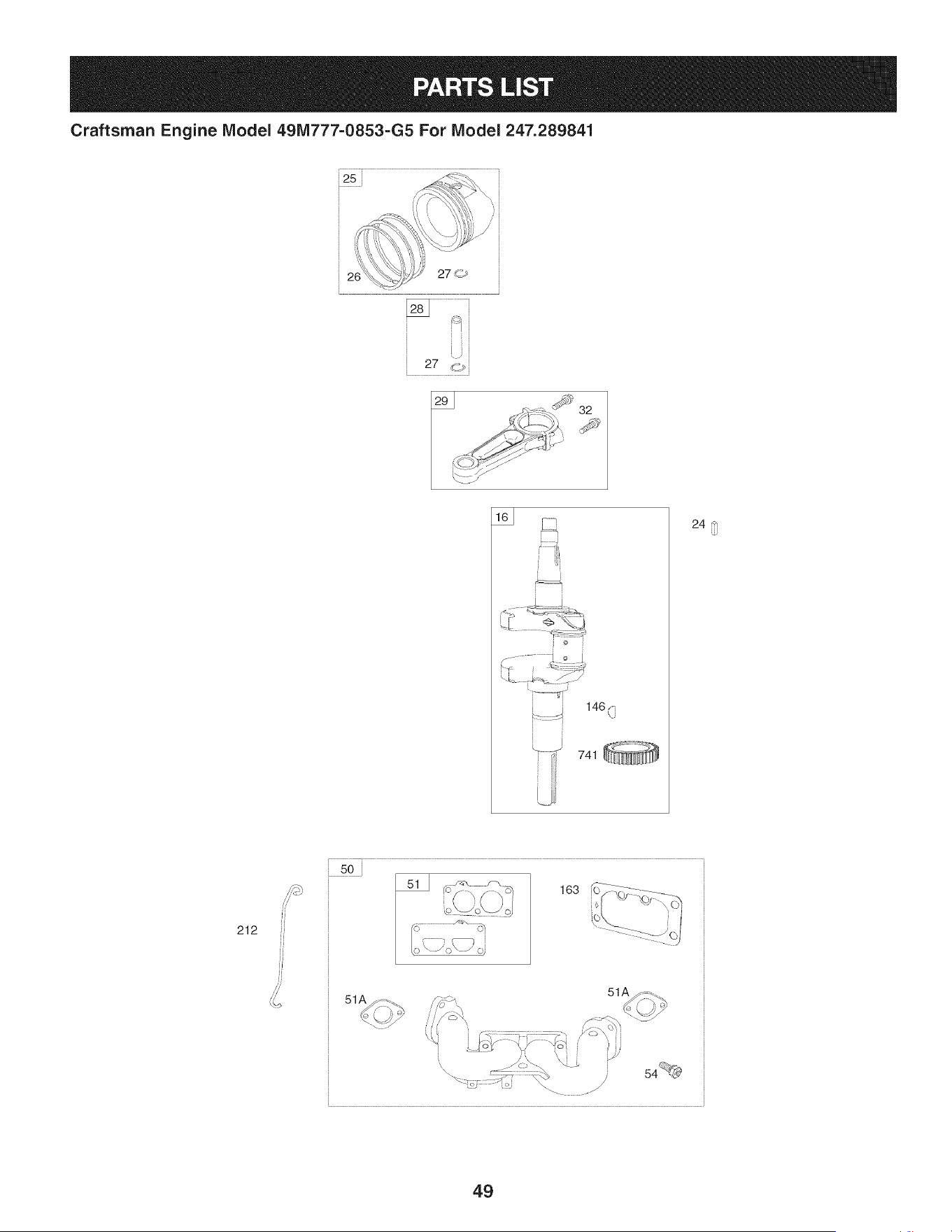
Craftsman Engine IViodel 491Vi777=0853=G5 For IViodel 247.289841
25 _._
' ,_\
_-_-_ <i,,,--_x_t!i',!' /
27 dT_i
i o
!.... j 146C7
i f
240
212
50
163 (O-}__--_-Z:-'--_
] ----<-- '(_j
51A
51A
\
/
L
49
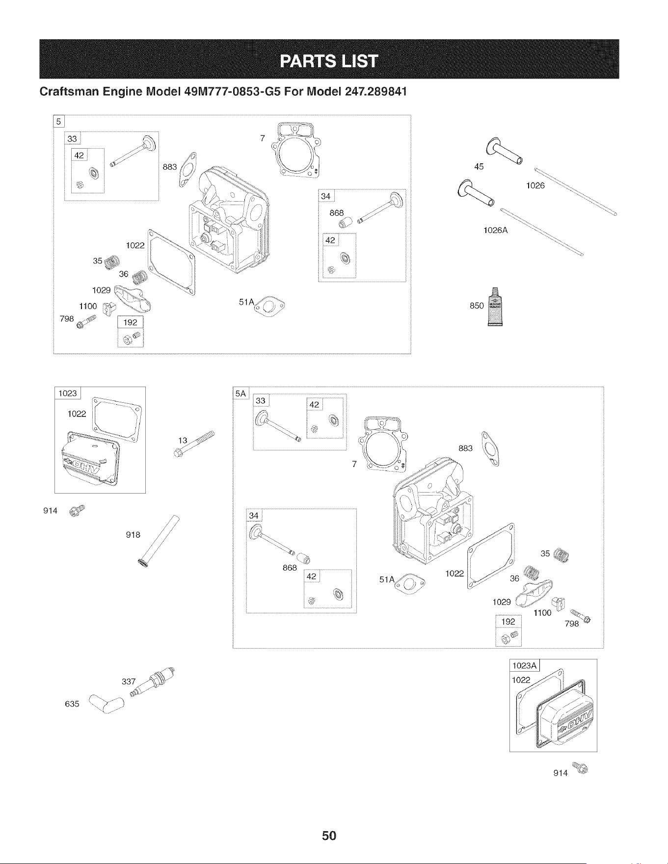
Craftsman Engine IViodel 491Vi777=0853=G5 For IViodel 247.289841
1022
883 45
1026 "_-_
85O
914
868 .....................................................
1O22
1029
635
1
914
50
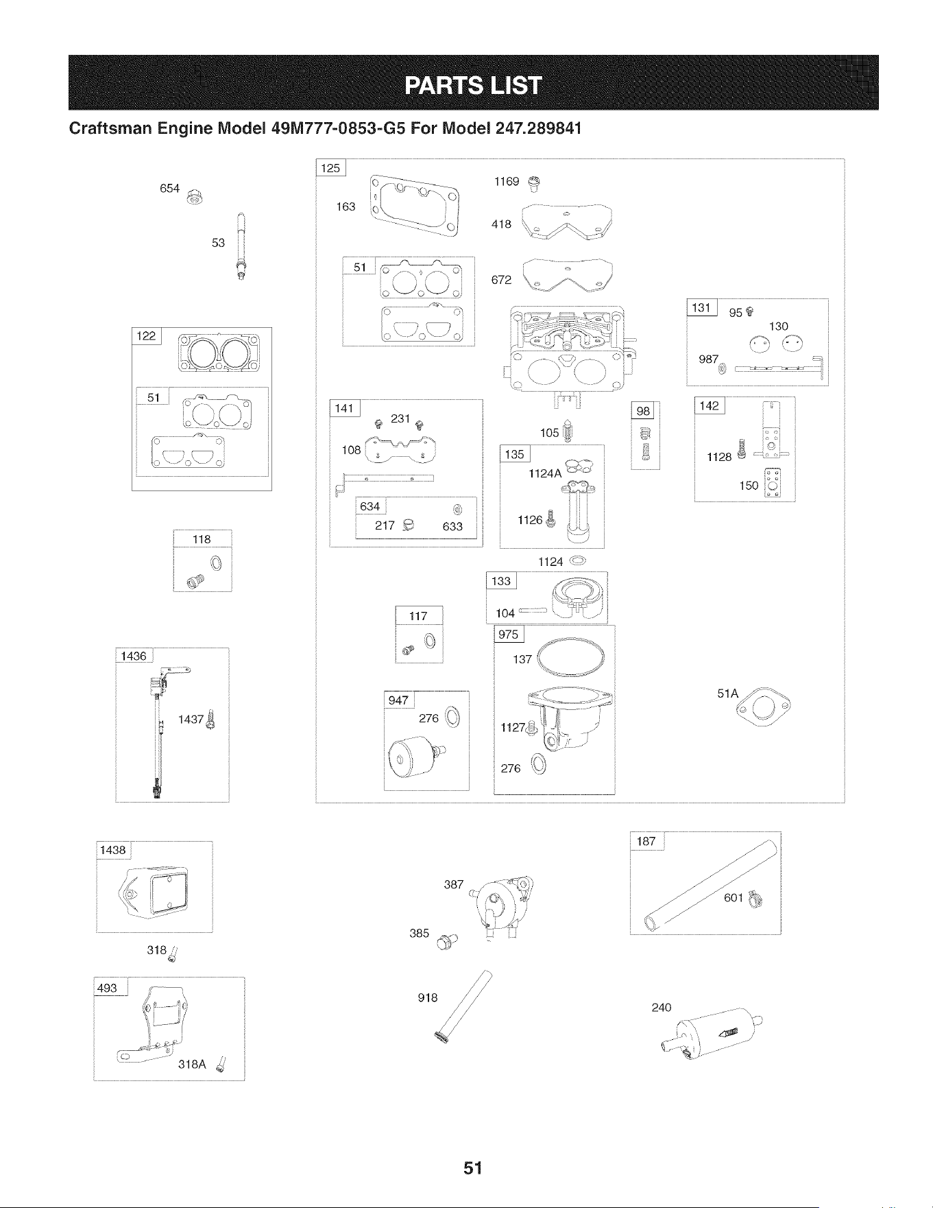
Craftsman Engine IViodel 491Vi777-0853-G5 For IViodel 247.289841
654
53 i
1169
163
418 _. _..._. ::::_/
672 X< /'\ _/
130
F_ S" :",
987 :_
}
15o_j i
118
14361
1437_
117
i947
276 _
1124 _:_
1438
318_.,
P
.... -\
i_ ii i ,i
385 _ lJ
24O
51
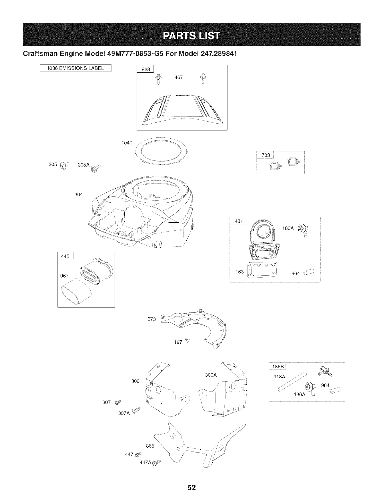
Craftsman Engine IViodel 491Vi777=0853=G5 For IViodel 247.289841
1036 EMiSSiONS LABEL
467
305 _(;) 305A ....._
1040
7O3
304
431 186A _
J i
163 964 d; -b
/
573
306
186B
918A
964
186A
52
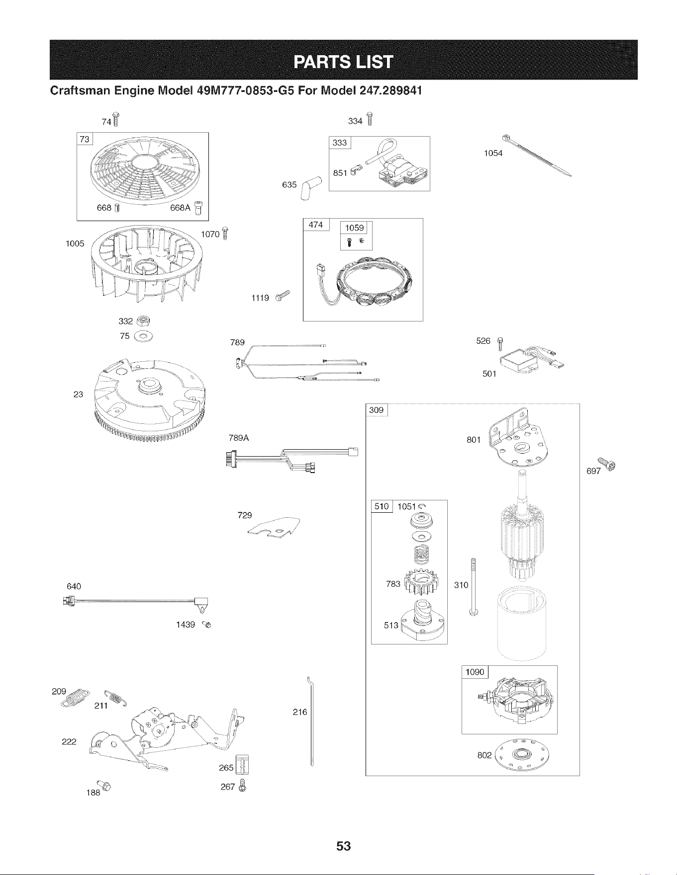
Craftsman Engine IViodel 491Vi777=0853=G5 For IViodel 247.289841
74_
334
o35_
i i
1005
1070
1119 G_<_
23
640
1439 _-_
222
789
789A
729
(
216
520
501
1051 _
783
801
310I>
i" i ,
8O2
53
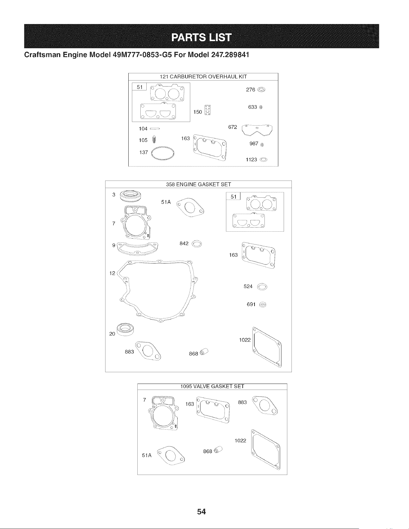
Craftsman Engine Model 49M777=0853=G5 For Model 247.289841
121 CARBURETOR OVERHAUL KiT
276 C_-I)
150
633 0)
358 ENGINE GASKET SET
51A
842_
163
12
524
691 (_:;:_)
2O
1095 VALVE GASKET SET
163 883
51A
1O22
54

Craftsman Engine IViodel 491Vi777=0853-G5 For IViodel 247.289841
96908 CylinderAssembly
2 499585 Bushing/Seal Kit (MagnetoSide)
3 391086s Seal-Oil (MagnetoSide) 98 699721
4 797502 Sump-Engine 104 694918
5 799088 Head-Cylinder(Cylinder1) 105 797410
5A 799089 Head-Cylinder(Cylinder2) 108 699723
7 796851 Gasket-CylinderHead 117 842633
8 792185 BreatherAssembly 118 842082
9 690937 Gasket-Breather 121 796919
10 697551 Screw(BreatherAssembly) 122 796877
11 792184 Tube-Breather 125 796870
12 697227 Gasket-Crankcase 130 796875
13 793988 Screw(CylinderHead) 131 796872
16 796857 Crankshaft 133 699724
20 795387 Seal-Oil (PTOSide) 135 699729
22 694966 Screw(CrankcaseCover/Sump) 137 690994
23 691053 Flywheel 141 796228
24 796335 Key-Flywheel(Steel) 142 796871
25 796909 PistonAssembly(Standard) 146 690979
796910 PistonAssembly(020" Oversize) 150 690995
26 796911 RingSet (Standard) 163 691001
796912 RingSet (.020"Oversize) 186 796532
27 690975 Lock-PistonPin 186A 845141
28 696581 Pin-Piston 186B 799158
29 796209 Rod-Connecting 187 791766
32 690976 Screw(ConnectingRod) 188 697551
33 793557 Valve-Exhaust 192 690083
197 697820
209 798921
211 691019
34 793556 Valve-Intake
35 694865 Spring-Valve(Intake)
36 694865 Spring-Valve(Exhaust)
42 499586 Keeper-Valve
45 690977 Tappet-Valve
46 796853 Camshaft
48 797511 Short Block
50 796878 Manifold-Intake
51 796876 Gasket-Intake
51A 690949 Gasket-Intake
53 690951 Stud (Carburetor)
54 699816 Screw(IntakeManifold)
73 494439 Screen-Rotating
74 698425 Screw(RotatingScreen)
D = 0 0
691056 Washer(Flywheel)
95 690718 Screw(ThrottleValve)
Kit-IdleSpeed
Pin-FloatHinge
Valve-FloatNeedle
Valve-Choke
Jet-Main(Standard)(Left and RightJet)
Jet-Main(HighAltitude)(Leftand RightJet)
Kit-CarburetorOverhaul
Spacer-Carburetor
Carburetor
Valve-Throttle
Kit-ThrottleShaft
Float-Carburetor
Tube-FuelTransfer
Gasket-FloatBowl
Kit-ChokeShaft
Nozzle-Carburetor
Key-Timing
Gasket-Nozzle
Gasket-AirCleaner
Connector-Hose(Oil DrainHose)
Connector-Hose(EVAPSystem)
Connector-Hose(EVAPSystem)
Line-Fuel(Cut to RequiredLength)
Screw(ControlBracket)
Adjuster-RockerArm
Screw(Back Plate)
Spring-Governor(Orange)
Spring-GovernedIdle (No Color)
212 695238 Link-Throttle
216 796879 Link-Choke
217 695409 Spring-ChokeReturn
219 793338 Gear-Governor
220 690412 Washer(GovernorGear)
221 841026 Cup-Governor
222 798916 Bracket-Control
227 798856 Lever-GovernorControl
231 690718 Screw(ChokeValve)
240 695666 Filter-Fuel
250 690957 Retainer-Breather
55

Craftsman Engine IViodel 491Vi777=O853=G5 For IViodel 247.289841
D = O !
794389 Collector-Oil
265 691024 Clamp-Casing
267 792629 Screw(CasingClamp)
276 695410 Washer-Sealing
278 792651 Washer(GovernorControlLever)
287 697551 Screw(DipstickTube)
304 797407 Housing-Blower
305 691005 Screw(BlowerHousing)
Screw(Blower Housing)(BlowerHousing
305A 790690
to IntakeElbow)
306 796852 Shield-Cylinder(Cylinder1)
306A 796541 Shield-Cylinder(Cylinder2)
307 691003 Screw(CylinderShield) (10-24x.43)
307A 697551 Screw(CylinderShield)(1/4-20x.62)
309 795121 Motor-Starter
310 691263 Screw(Starter Motor)
Screw(MountingBracket)(Electronic
318 792629
ChokeModule)(10-32x.70)
Screw(MountingBracket)(Electronic
318A 691127
ChokeModule)(1/4-20x.81)
332 691059 Nut (Flywheel)
333 691060 Armature-Magneto
334 691061 Screw(MagnetoArmature)
337 491055s Plug-Spark
358 796917 GasketSet-Engine
385 797409 Screw(Fuel Pump)
387 808656 Pump-Fuel
400 796882 Cooler-Oil
404 690442 Washer(GovernorCrank)
415 794903 Plug(Oil PressureSwitch Hole)
418 795912 Plate-Carburetor
431 798860 Elbow-Intake
445 792105 Filter-AirCleaner Cartridge
447 691003 Screw(Air GuideCover)(10-24x.43)
447A 697551 Screw(Air GuideCover)(1/4-20x.62)
448 796865 Bracket-OilCooler
467 790697 Knob-Air Cleaner
474 696458 Alternator
493 797176 Bracket-Mounting(ElectronicChoke
Module)
501 797375 Regulator
505 691029 Nut (GovernorControlLever)
D = O O
696541 Drive-Starter
512 796530 Hose-OilDrain
513 692024 Clutch-Drive
523 691036 Dipstick
524 691032 Seal-DipstickTube
525 691037 Tube-Dipstick
523 697551 Screw(Regulator)
552 796638 Bushing-GovernorCrank
552A 690553 Bushing-GovernorCrank
562 690311 Screw(GovernorControl Lever)
573 790444 Plate-Back
601 691038 Hose-Clamp(Black)
601A 841597 Hose-Clamp(Oil CoolerHose)
615 698290 Retainer-GovernorShaft
616 691045 Crank-Governor
633 699813 Seal-Choke/ThrottleShaft (ChokeShaft)
634 698779 Spring/SealAssembly(ChokeShaft)
635 692076 Boot-SparkPlug
640 796913 Wire-Thermistor
654 690958 Nut (Carburetor)
668 691215 Spacer(RotatingScreen)
668A 691500 Spacer(RotatingScreen)
672 690234 Gasket-CarburetorPlate
691 790574 Seal-GovernorShaft
697 690372 Screw(DriveCap)
703 691010 Clip
718 690959 Pin-Locating
729 797454 Clip-Wire
741 690980 Gear-Timing
742 690328 Retainer-ERing
750 796208 Screw(Oil PumpCover)
783 695708 Gear-Pinion
789 796860 Harness-Wiring
789A 796914 Harness-Wiring
798 697890 Screw(RockerArm)
801 691283 Cap-Drive
802 691286 Cap-End
829 796867 Hose-OilCooler
842 691031 Seal-O Ring(DipstickTube)
847 499602 Dipstick/TubeAssembly
850 100106 Sealant-Liquid
56
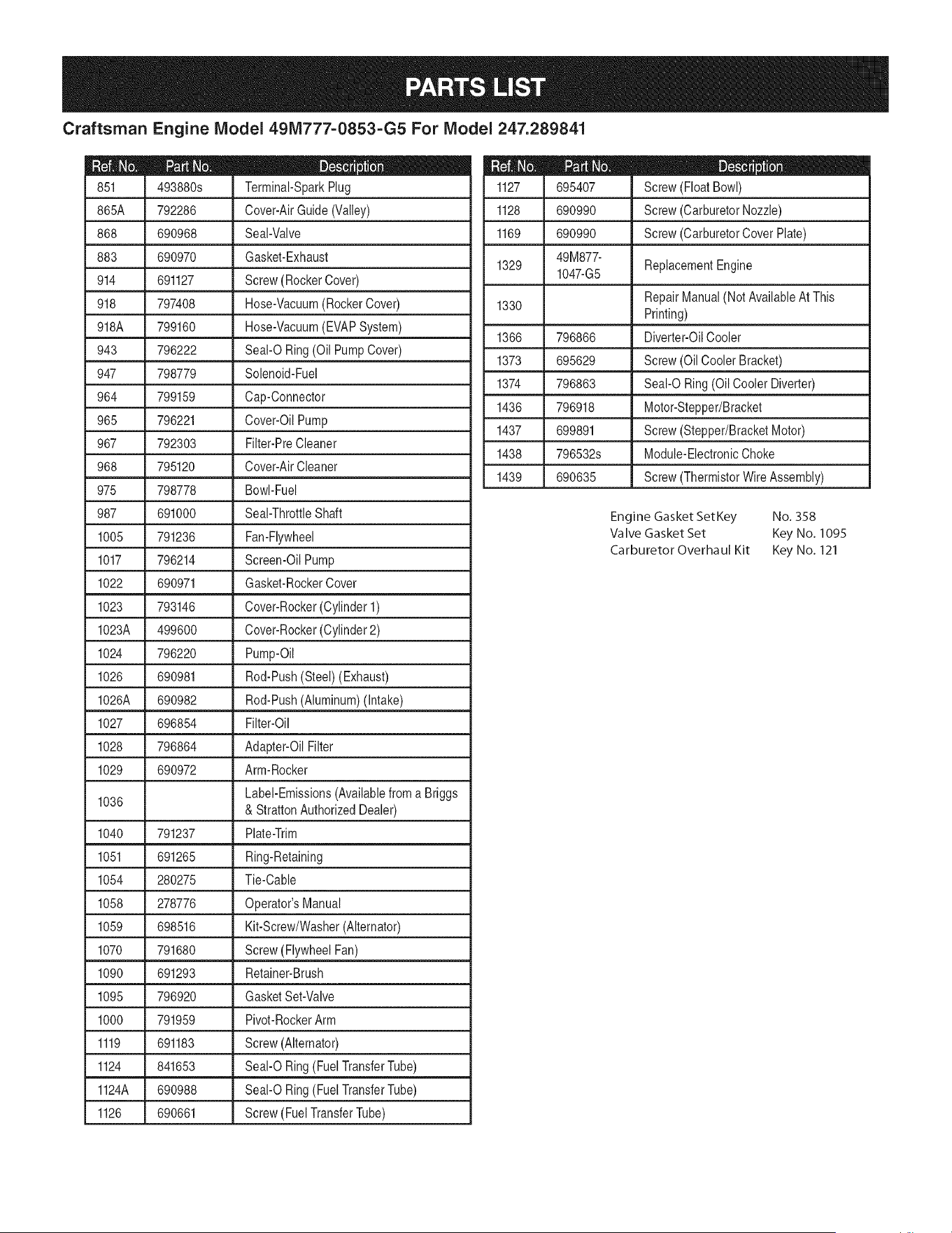
Craftsman Engine Model 491Vi777=O853=G5 For Model 247.289841
D = O
493880s Terminal-SparkPlug
865A 792286 Cover-AirGuide(Valley)
868 690968 Seal-Valve
883 690970 Gasket-Exhaust
914 691127 Screw(RockerCover)
918 797408 Hose-Vacuum(RockerCover)
918A 799160 Hose-Vacuum(EVAPSystem)
943 796222 Seal-O Ring (Oil PumpCover)
947 798779 Solenoid-Fuel
964 799159 Cap-Connector
965 796221 Cover-OilPump
967 792303 Filter-PreCleaner
968 795120 Cover-AirCleaner
975 798778 Bowl-Fuel
987 691000 Seal-ThrottleShaft
1005 791236 Fan-Flywheel
1017 796214 Screen-Oil Pump
1022 690971 Gasket-RockerCover
1023
793146 Cover-Rocker(Cylinder 1)
1023A 499600 Cover-Rocker(Cylinder2)
1024 796220 Pump-Oil
1026 690981 Rod-Push(Steel)(Exhaust)
1026A 690982 Rod-Push(Aluminum)(Intake)
1027 696854 Filter-Oil
1028 796864 Adapter-OilFilter
1029 690972 Arm-Rocker
Label-Emissions(Availablefrom a Briggs
1036
& StrattonAuthorizedDealer)
1040 791237 Plate-Trim
1051 691265 Ring-Retaining
1054 280275 Tie-Cable
1058 278776 Operator'sManual
1059 698516 Kit-Screw/Washer(Alternator)
1070 791680 Screw(FlywheelFan)
1090 691293 Retainer-Brush
1095 796920 GasketSet-Valve
1000 791959 Pivot-RockerArm
1119 691183 Screw(Alternator)
1124 841653 Seal-O Ring (FuelTransferTube)
1124A 690988 Seal-O Ring (Fuel TransferTube)
1126 690661 Screw(FuelTransferTube)
I = O O
695407 Screw(FloatBowl)
1128 690990 Screw(CarburetorNozzle)
1169 690990 Screw(CarburetorCoverPlate)
49M877-
1329 1047-G5 ReplacementEngine
1330 RepairManual(NotAvailableAt This
Printing)
1366 796866 Diverter-OilCooler
1373 695629 Screw(OilCooler Bracket)
1374 796863 Seal-O Ring(Oil CoolerDiverter)
1436 796918 Motor-Stepper/Bracket
1437 699891 Screw(Stepper/BracketMotor)
1438 796532s Module-ElectronicChoke
1439 690635 Screw(ThermistorWireAssembly)
Engine Gasket SetKey No. 358
Valve Gasket Set Key No. 1095
Carburetor Overhaul Kit Key No. 121
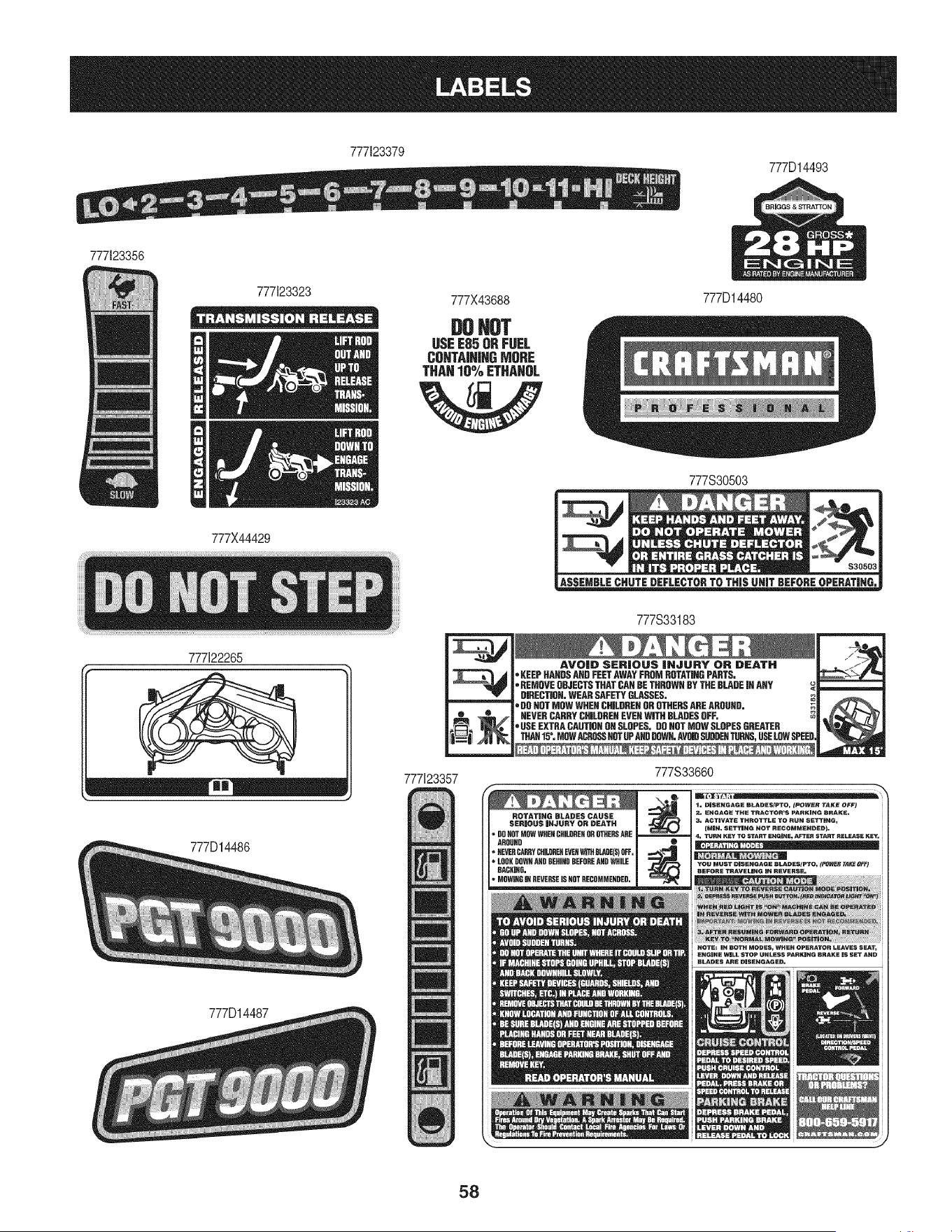
777123379
777D14493
777123356
777X44429
777122265
777D14486
777D14487
777X43688 777D14480
DOHOT
USEE85ORFUEL
CUNTA|N|HGMORE
THAN10%ETHAHOL
i_,dJ
777123357
777S30503
mmz_ $30503
777S33183
AVOID SERIOUS |NJURY OR DEATH
_'KEEPHANGSANDFEETAWAYFROMROTATINGPARTS.
,REMOVEOBJECTSTHATCANBETHROWNBYTHEBLADEJNANY
DIRECTION,WEARSAFETYGLASSES.
,DOHOTMOWWRENCHILDRENOROTHERSAREAROUND.
NEVERCARRYCHILDREHEVEHWiTHBLADESOFF.
,USEEXTRACAUTJQHONSLOPES.DOHOTMOWSLOPESGREATER
THAN15°, MOWACROSSHOTOFAHDDOWN.AVW SUDDENTUBHS,USELOWSPEE
777S33660
CHILDREHOR_ERS ARE
AROUND J •
_HIHH BEFOREANDWHILE J
HACHIHG. I
_RSE ISN_ RECOMMEHDED.
58
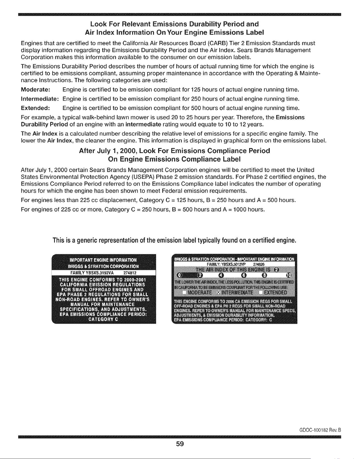
Look For Relevant Emissions Durability Period and
Air index information On Your Engine Emissions Label
Engines that are certified to meet the California Air Resources Board (CARB) Tier 2 Emission Standards must
display information regarding the Emissions Durability Period and the Air Index. Sears Brands Management
Corporation makes this information available to the consumer on our emission labels.
The Emissions Durability Period describes the number of hours of actual running time for which the engine is
certified to be emissions compliant, assuming proper maintenance in accordance with the Operating & Mainte-
nance Instructions. The following categories are used:
Moderate: Engine is certified to be emission compliant for 125 hours of actual engine running time.
Intermediate: Engine is certified to be emission compliant for 250 hours of actual engine running time.
Extended: Engine is certified to be emission compliant for 500 hours of actual engine running time.
For example, a typical walk-behind lawn mower is used 20 to 25 hours per year. Therefore, the Emissions
Durability Period of an engine with an intermediate rating would equate to 10 to 12 years.
The Air index is a calculated number describing the relative level of emissions for a specific engine family. The
lower the Air Index, the cleaner the engine. This information is displayed in graphical form on the emissions label.
After July 1,2000, Look For Emissions Compliance Period
On Engine Emissions Compliance Label
After July 1, 2000 certain Sears Brands Management Corporation engines will be certified to meet the United
States Environmental Protection Agency (USEPA) Phase 2 emission standards. For Phase 2 certified engines, the
Emissions Compliance Period referred to on the Emissions Compliance label indicates the number of operating
hours for which the engine has been shown to meet Federal emission requirements.
For engines less than 225 cc displacement, Category C = 125 hours, B = 250 hours and A = 500 hours.
For engines of 225 cc or more, Category C = 250 hours, B = 500 hours and A = 1000 hours.
This is a generic representation of the emission label typically found on a certified engine.
FAMILYYBSXS.3192VA 274812
GDOC-100182Rev.B
59
(Thispageapplicablein the U.S.A.and Canadaonly.)
Sears Brands Management Corporation (Sears), the California Air Resources Board (CARD)
and the United States Environmental Protection Agency (U.S. EPA)
Emission Control System Warranty Statement (Owner's Defect Warranty Rights and Obligations)
EMISSIONCONTROLWARRANTYCOVERAGEISAPPLICABLETOCERTI-
FIEDENGINESPURCHASEDIN CALIFORNIAIN 1995ANDTHEREAF-
TER,WHICHARE USEDINCALIFORNIA,ANDTOCERTIFIEDMODEL
California and United States Emission
The CaliforniaAir ResourcesBoard(CARD),U.S.EPAand Searsare pleased
to explainthe EmissionControlSystemWarrantyon your modelyear2000and
latersmalloff-roadengine(SORE).InCalifornia,newsmall off-roadengines
mustbe designed,builtand equippedto meettheState'sstringentanti-smog
standards.Elsewherein theUnitedStates, newnon-road,spark-ignition
enginescertifiedfor modelyear 1997and latermustmeetsimilarstandardsset
forth bythe U.S.EPA.Sears mustwarrantthe emissioncontrol systemonyour
YEAR 1997AND LATERENGINESWHICHARE PURCHASEDAND USED
ELSEWHEREIN THE UNITEDSTATES(ANDAFTERJANUARY1,2001 IN
CANADA).
Control Defects Warranty Statement
enginefor theperiodsoftime listedbelow,providedtherehas been noabuse,
neglector impropermaintenanceof your smalloff-roadengine.Youremis-
sion controlsystemincludespartssuch as thecarburetor,air cleaner,ignition
system,mufflerand catalyticconverter.Also includedmay be connectorsand
otheremissionrelatedassemblies.Wherea warrantableconditionexists,Sears
will repairyour smalloff-roadengineat no costto you includingdiagnosis,parts
and labor.
Sears Emission Control Defects Warranty Coverage
Smalloff-roadenginesarewarrantedrelativeto emissioncontrol partsdefects
fora periodof one year,subjectto provisionsset forth below.Ifany covered
Owner's Warranty
Asthe smalloff-roadengine owner,you are responsiblefor the performanceof
therequiredmaintenancelistedin yourOperatingand MaintenanceInstruc-
tions.Searsrecommendsthatyou retain all yourreceiptscoveringmaintenance
on yoursmalloff-roadengine,butSears cannotdenywarrantysolelyfor the
lackof receiptsor for yourfailureto ensuretheperformanceof all scheduled
maintenance.As the smalloff-roadengineowner,you shouldhoweverbe
awarethat Searsmaydenyyou warrantycoverageif your smalloff-roadengine
ora part hasfailed dueto abuse,neglect,impropermaintenanceor unap-
parton yourengineis defective,the part will be repairedorreplacedbySears.
Responsibilities
provedmodifications.Youare responsiblefor presentingyour smalloff-road
engineto an AuthorizedSearsServiceDealeras soonas a problemexists.The
undisputedwarrantyrepairsshouldbe completedina reasonableamountof
time,notto exceed30 days. Ifyou haveany questionsregardingyourwarranty
rightsand responsibilities,you shouldcontacta SearsService Representative
at 1-800-469-4663.The emissionwarrantyis a defectswarranty.Defectsare
judgedon normalengineperformance.Thewarrantyis not relatedto an in-use
emissiontest.
Sears Emission Control Defects Warranty Provisions
ThefollowingarespecificprovisionsrelativetoyourEmissionControlDefectsWarrantyCoverage.Itisin additiontotheSearsenginewarrantyfornon-regulated
enginesfound in theOperatingand MaintenanceInstructions.
1. WarrantedParts
Coverageunderthis warrantyextendsonly to the parts listedbelow (the
emissioncontrolsystemsparts)to the extentthese partswere presenton
the engine purchased.
a. FuelMeteringSystem
• Cold start enrichmentsystem
• Carburetorand internalparts
• FuelPump
b. Air lnduction System
• Air cleaner
• Intakemanifold
c. IgnitionSystem
• Spark plug(s)
• Magnetoignitionsystem
d. CatalystSystem
• Catalyticconverter
• Exhaustmanifold
• Air injectionsystemor pulsevalve
e. MiscellaneousItemsUsedin AboveSystems
• Vacuum,temperature,position,timesensitivevalves
andswitches
• Connectorsandassemblies
2. Lengthof Coverage
Searswarrantsto the initialownerand eachsubsequentpurchaserthat
the WarrantedParts shallbe free from defects in materialsandworkman-
shipwhich causedthe failure of the WarrantedPartsfor a periodof one
yearfrom the datethe engineis deliveredto a retailpurchaser.
3. NoCharge
Repairor replacementof anyWarrantedPartwill beperformedat no
chargeto the owner,includingdiagnosticlabor whichleads to the
determinationthata WarrantedPartis defective,if the diagnosticworkis
performedat an AuthorizedSears ServiceDealer.Foremissionswarranty
servicecontact yournearestAuthorizedSearsServiceDealeras listed in
the "YellowPages"under"Engines,Gasoline,""GasolineEngines,""Lawn
Mowers,"or similar category.
4. Claimsand CoverageExclusions
Warrantyclaimsshall be filed in accordancewith the provisionsof the
Sears EngineWarrantyPolicy.Warrantycoverageshall be excludedfor
failuresof WarrantedPartswhichare notoriginal Sears partsor because
of abuse, neglector impropermaintenanceas setforth inthe Sears
EngineWarrantyPolicy.Sears is notliableto coverfailuresof Warranted
Partscausedby theuse of add-on, non-original,or modifiedparts.
5. Maintenance
Any WarrantedPart whichis not scheduledfor replacementas required
maintenanceor whichis scheduledonly for regularinspectionto the effect
of "repairor replaceas necessary"shallbe warrantedasto defectsfor the
warrantyperiod.Any WarrantedPartwhich is scheduledfor replacement
as requiredmaintenanceshallbe warrantedasto defectsonly forthe
periodof time upto the firstscheduledreplacementfor that part. Any
replacementpart that is equivalentin performanceand durabilitymay
be usedin the performanceof any maintenanceor repairs.The owneris
responsibleforthe performanceof all requiredmaintenance,as definedin
the SearsOperatingand MaintenanceInstructions.
6. ConsequentialCoverage
Coveragehereundershallextend to thefailure of any engine components
caused bythe failureof any WarrantedPartstill underwarranty.
Inthe USAandCanada,a 24 hour hotline, 1-800-469-4663,has a menu of pre-recordedmessagesofferingyou enginemaintenanceinformation.
GD0C-100188Rev.B
60
FEDERAL and/or CALIFORNIA EMISSION CONTROL WARRANTY STATEMENT
YOUR WARRANTY RIGHTS AND OBLIGATIONS
MTDConsumerGroupInc,the UnitedStatesEnvironmentalProtectionAgency (EPA),and, forthose productscertifiedfor sale in the stateof California,the
CaliforniaAir ResourcesBoard(CARB)are pleasedto explainthe emission(evaporativeand/or exhaust)controlsystem(ECS) warrantyon youroutdoor2006
andlater smalloff-roadspark-ignitedengine andequipment(outdoorequipmentengine)In California,new outdoorequipmentenginesmustbedesigned,built and
equippedto meetthe State'sstringentanti-smogstandards(inotherstates, 1997andlater modelyear equipmentmustbe designed,built, and equippedto meet
theU.S. EPAsmalloff-road, sparkignitionengine regulations.MTDConsumerGroupInc mustwarrantthe ECSon your outdoorequipmentenginefor the periodof
timelisted belowprovidedtherehas been no abuse,neglector impropermaintenanceof outdoor equipmentengine.
Your ECSmay includeparts such as thecarburetor,fuel-injectionsystem,the ignitionsystem,catalyticconverter,fuel tanks,fuel lines,fuel caps, valves,canisters,
filters,vapor hoses,clamps,connectors,andotherassociatedemission-relatedcomponents.
Wherea warrantableconditionexists, MTDConsumerGroupIncwill repairyouroutdoor equipmentengine at no cost to you includingdiagnosis,parts and labor.
MAN UFACTURER'S WARRANTY COVERAGE:
Thisemissioncontrolsystemis warrantedfor two years. If any emission-relatedpart on your outdoorequipmentengineis defective,the part will berepairedor
replacedby MTDCONSUMERGROUPINC.
OWNER'S WARRANTY RESPONSIBILITIES:
Asthe outdoorequipmentengineowner,you are responsiblefor performanceof the requiredmaintenancelisted in your owner'smanual.MTDConsumerGroup
Inc recommendsthat you retain all receiptscoveringmaintenanceon youroutdoorequipmentengine,butMTDConsumerGroupInc cannotdeny warrantysolely
forthe lackof receipts.
Asthe outdoorequipmentengineowner,you shouldhoweverbe awarethat MTDConsumerGroupInc maydenyyou warrantycoverageif your outdoorequipment
engineor a part has failed due to abuse, neglect,or impropermaintenanceor unapprovedmodifications.
Youare responsiblefor presentingyouroutdoor equipmentengineto MTDConsumerGroupInc'sdistributioncenterorservicecenteras soon asthe problem
exists.The warrantyrepairsshouldbe completedin a reasonableamountof time, notto exceed30 days.If you havea questionregardingyour warrantycoverage,
you shouldcontactthe MTDConsumerGroupIncService Departmentat 1-800-800-7310orvia emailat http://support.mtdproducts.com
GENERAL EMISSIONS WARRANTY COVERAGE:
MTDConsumerGroupIncwarrantsto the ultimatepurchaserand eachsubsequentpurchaserthat theoutdoorequipmentengineis: Designed,built and equipped
so asto conformwithall applicableregulations;and freefrom defects in materialsand workmanshipthatcausethe failureof a warrantedpart to be identicalin all
materialrespectsto that part as describedin MTDConsumerGroup Inc'sapplicationfor certification.
The warrantyperiodbeginson the date the outdoorequipmentengine is deliveredto an ultimate purchaseror first placedinto service.The warrantyperiod is two
years.
Subjectto certain conditionsand exclusionsasstated below,the warrantyon emission-relatedparts is asfollows:
1. Any warrantedpart that is notscheduledfor replacementas requiredmaintenancein thewritten instructionssupplied, is warrantedforthe warrantyperiod
statedabove. Ifthe part fails duringthe periodof warrantycoverage,thepart will berepairedor replacedbyMTDConsumerGroupInc accordingto subsection
(4) below. Anysuch part repairedor replacedunderwarrantywill be warrantedfor the remainderof the period.
2. Any warrantedpart that is scheduledonly for regularinspectionin the writteninstructionssupplied is warrantedforthe warrantyperiodstatedabove.Any such
part repairedor replacedunderwarrantywill be warrantedforthe remainingwarrantyperiod.
3. Any warrantedpart that is scheduledfor replacementas requiredmaintenancein thewritten instructionssuppliedis warrantedfor the periodof timebeforethe
first scheduledreplacementdatefor that part. If the partfails beforethefirst scheduledreplacement,the part will berepairedor replacedby MTDConsumer
GroupInc accordingto subsection(4) below.Any such part repairedor replacedunderwarrantywill bewarrantedfor the remainderof the periodprior to the
first scheduledreplacementpointfor the part.
4. Repairor replacementof any warrantedpart underthe warrantyprovisionshereinmustbe performedat a warrantystationat no chargeto the owner.
5. Notwithstandingthe provisionsherein,warrantyservicesor repairswill be providedat all of our distributioncentersthatare franchisedto servicethe subject
enginesor equipment.
6. The outdoorequipmentengine ownerwill notbe chargedfor diagnostic laborthat is directlyassociatedwithdiagnosisof a defective,emission-relatedwar-
rantedpart, providedthat suchdiagnosticwork is performedat a warrantystation.
7. MTDConsumerGroupInc is liablefor damagesto otherengine or equipmentcomponentsproximatelycausedby a failure underwarrantyof any warranted
part.
8. Throughoutthe off-roadengineand equipmentwarrantyperiodstatedabove, MTDConsumerGroupInc will maintaina supplyof warrantedparts sufficientto
meetthe expecteddemandfor such parts.
9. Any replacementpart may be usedin the performanceof any warrantymaintenanceor repairsand mustbe providedwithoutchargeto the owner.Suchuse will
notreducethe warrantyobligationsof MTDConsumerGroupInc.
10.Add-onor modifiedpartsthat are not exemptedbythe Air ResourcesBoardmay not be used.The use of any non-exemptedadd-on or modifiedparts by the
ultimatepurchaserwill begroundsfor disallowinga warrantyclaims. MTDConsumerGroup Incwill notbe liableto warrantfailuresof warrantedparts caused
bythe useof a non-exemptedadd-onor modifiedpart.
WARRANTED PARTS:
The repairor replacementof any warrantedpart otherwiseeligiblefor warrantycoveragemay be excludedfrom such warrantycoverageif MTDConsumerGroup
Inc demonstratesthatthe outdoorequipmentenginehas beenabused,neglected,or improperlymaintained,and thatsuch abuse, neglect,or impropermainte-
nancewasthe direct causeof the needfor repairor replacementof the part.Thatnotwithstanding,any adjustmentof a componentthat hasa factory installed,
andproperlyoperating,adjustmentlimitingdeviceis still eligible for warrantycoverage. Further,the coverageunderthis warrantyextendsonly to partsthat were
presenton the off-roadengineand equipmentpurchased.
Thefollowing emissionwarrantypartsare covered(if applicable):
(1) FuelMeteringSystem
• Cold start enrichmentsystem(softchoke)
• Carburetorand internalparts (or fuel injectionsystem)
• Fuelpump
• Fueltank
(2) Air InductionSystem
• Air cleaner
• Intakemanifold
(3) IgnitionSystem
• Spark plug(s)
• Magnetoignitionsystem
(4) ExhaustSystem
• Catalyticconverter
• SAI (Reed valve)
(5) MiscellaneousItemsUsedin AboveSystem
• Vacuum,temperature,position,timesensitivevalvesand switches
• Connectorsandassemblies
(6) EvaporativeControl
• Fuelhose
• Fuelhoseclamps
• Tetheredfuel cap
• Carboncanister
• Vapor lines
GDOC-100223Rev.A
Declaracion de garantia ........................ 63
Instrucciones sobre seguridad ................... 64
Guia Para Pendientes .......................... 69
Montaje ..................................... 71
Conozca su cortadora de cesped ................. 74
Funcionamiento ............................... 77
Servicio y Mantenimiento ....................... 80
Almacenamiento fuera de temporada .............. 90
Solucion de Problemas ......................... 92
Lista de piezas ............................... 34
NOmeros de servicio .................... Contratapa
CRAFTSMAN PROFESIONALES DE GARANT|A
PORDOSANOSa partirdelafechadecompra,todaslaspartesnofungiblesdeesteequipodeequitaci6nest_ngarantizadoscontracualquierdefecto
dematerialomanodeobra.Unapiezadefectuosano fungiblesrecibirAnreparaci6ngratuitaen el hogaro la sustituci6nsila reparaci6nesimposible.
Durantecincoaios desdelafechadecompra,elejedelmarcoy el frentede esteequipodeequitaci6nest£ngarantizadoscontracualquierdefectode
materialo manodeobra.Uncuadrodefectuosoo eje delanterorecibirAreparaci6ngratuitaenel hogaro lasustituci6nsila reparaci6nes imposible.
Todoslosde la coberturade la garanfiaanteriorse aplicaparaun soloaio desdelafechadecomprasi el equipode montara caballoes utilizadoalguna
vez,mientrasquelaprestaci6ndeservicioscomercialeso sisealquilaa otrapersona.
POR90DiASa partirdelafechadecompra,labateria(unapartefungibles)de esteequipode equitaci6nest_garantizadacontracualquierdefectode
materialo manodeobra(nuestraspruebasdemuestraqueno mantienela carga).UnabateriadefectuosarecibirAreemplazogratuitoenelhogar.
ADICIONALDE GARANTiALIMITADADE PORVlDAen FUNDICIONeje delantero(si est_ instalado)
PARASIEMPREY CUANDOSE UTILIZAporelpropietariooriginaldespu_sdel quintoaSodesdelafechadecompra,elhierrofundidoejedelantero
(si existe)de esteequipodeequitaci6nest_garantizadacontracualquierdefectodematerialeso manodeobra.Conelcomprobantede compra,uneje
delanterofundidodefectuosorecibir_reemplazogratuitoenelhogar.
GARANTiABESERVlCIO
Paraobtenerinformaci6ndetaladacoberturadelagarantaparaobtenerla reparaci6no sustituci6ngratuita,lameal 1-800-659-5917o visiteelsitioweb:www.
craftsman.com
Entodosloscasosanteriores,sila reparacbno reemplazodeunaparteesimposible,elequipodeequitacbnser_reemplazadodeformagratuitaconelmismoo
equivalente.
EstagarantacubrelosdefectosSOLOdematerialesyfabricaci6n.Lagarantanoincluye:
• Laspartesconsumibles(exceptolabateria)quepuedegastarseporelusonormaldentrodelperiododegaranta,incluyendoperonolimitadoa,cuchillas,
bujias,filtrosde aire,correasy filtrosdeaceite.
• Losserviciosdemantenimiento,cambiosdeaceite,o puestasa punto.
• Tireel reemplazoo reparacbndepinchazoscausadospotobjetosextemos,talescomoclavos,espinas,toconesovidrio.
• Tiredela ruedao el reemplazoolareparacbnresultantesdeldesgastenormal,accidenteo realfuncionamientoo mantenimiento.
• Lasreparacionesnecesariasdebidoalabusodeloperador,incluyendoperonolimitadoa losdaios causadosporel remolquedelosobjetosm_sall_dela
capaddaddelequipode equitaci6n,el impactodeobjetosquedoblenlaestructura,elmontajedelejeodelcigOe_al,odeexcesode velocidaddelmotor.
• Lasreparacionesnecesariasdebidoala neglgenciadeloperador,incluyendoperono limitadoa,da_osel_ctricosy mec_nicoscausadosporunalmace-
namientoinadecuado,noutilzaci6ndelacalidado cantdaddeaceitede motor,nomantenerelpisolbrederesiduosinflamables,o faltademantenimiento
delEquipoecuestrede acuerdoalasinstruccionescontenidasenelmanualdeloperador.
• Elmotor(sistemade combustible)delimpiezao reparacionesprovocadasporuncombustiblequesecontaminadouoxidado(viejo).Engeneral,el
combustibledebeserutilzadodentrodelos30diassiguientesalafechadecompra.
• deterioroy desgastenormaldelosacabadosexteriores,o reemplazodelaetiquetadelproducto.
Estagaranfiale otorgaderechoslegalesespecfficos,y ustedtambi_npuedetenetotrosderechosque variande estadoa estado.
Sears Brands ManagementCot
Aceitedel motor:
Combustible:
Bujias:
Motor:
SAE3O
Gasolinasin plomo
Champion®RC12YC
Briggs& StrattonProfessionalSeries
_oration,Hoffman Estates,IL 60179
N_mero de rnodelo
NSmerode sede
Fechade eompra
RegistrearribaelnOmerodel modelo,
el nOmerode seriey lafechadecompra
© KCD IRLLC 63
Lapresenciade estesirnboloindicaque setrata de instrucciones
irnportantesde seguridadque se debenrespetarparaevitar
ponerenpeligrosu seguridadpersonaly/o materialy lade otras
personas.Leay sigatodas lasinstruccionesde estemanualantes
de poneren funcionarnientoestarn_.quina.Si no respetaestas
instruccionespodria provocarlesionespersonales.Cuandoveaeste
sirnbolo,ipresteatenci6na la advertencia!
PROPOSICION 65 DE CALIFORNIA
Elescapedel motorde esteproducto,algunosde sus cornponentes
y algunoscornponentesdel vehiculocontieneno liberansustancias
quirnicasqueelestadode Californiaconsideraque puedenproducir
c_.ncer,defectosde nacirnientouotrosproblernasreproductivos.
Losbornesdela bateriay losaccesoriosdines contienenplornoy
cornpuestosde plorno,sustanciasquirnicasquesegQnIoestableci-
do pot el Estadode Californiacausanc_.ncery da_osen el sisterna
reproductivo.Ldveselas manos despu_sde estaren contacto
con estoscomponentes.
Estarn_.quinarueconstruidapara seroperadadeacuerdocon
las reglasde seguridadcontenidasen este manual.AI igualque
concualquiertipo deequipornotorizado,undescuidoo errorpor
partedel operadorpuedeproducirlesionesgraves.Estarn_.quina
es capazde arnputarrnanosy piesy de arrojarobjetoscon gran
fuerza.De norespetarlas instruccionesde seguridadsiguientesse
puedenproducirlesionesgraveso la rnuerte.
Su responsabilidad--Restrinja el usode estarn_.quina
rnotorizadaalas personasque lean,cornprendany respetenlas
advertenciase instruccionesqueaparecenen este manualyen la
rn_.quina.
iGUARI)E ESTASINSTRUCCIONES!
FUNCIONAMIENTO GENERAL
• Lea,entienday curnplatodaslas instruccionesincluidasen
la rn_.quinayen los rnanualesantesde rnontarlay utilizarla.
Guardeestemanualen un lugarseguroparaconsultasfuturasy
peri6dicas,asi cornopara solicitarrepuestos.
• Farniliaricesecontodoslos controlesy con el usoadecuado
de losrnisrnos.Sepa c6rnodetenerlarn_.quinay desactivarlos
controlesr_.pidarnente.
• No perrnitanuncaque losni_os rnenoresde 14a_osutilicen
estarn_.quina.Los ni_osde 14a_osen adelantedebenleery
entenderlas instruccionesde operaci6ny norrnasdeseguridad
contenidasen estemanual,yen la rn_.quinay debenser
entrenadosy supervisadosporun adulto.
• Nuncaperrnitaque los adultosoperenestarn_.quinasin recibir
antesla instrucci6napropiada.
• Paraayudara evitarelcontactocon las cuchillaso unalesi6npor
algQnobjetoque seaarrojado,rnantengaa los observadores,a
los ayudantes,ni_osy rnascotasalejadosal rnenos25 metrosde
la rn_.quinarnientrasest,. en funcionarniento.Detengala rn_.quina
si alguienentraen lazona.
• Inspeccionerninuciosarnenteel Areadondeutilizar_,el equipo.
Retiretodaslas piedras,palos,cables,huesos,juguetesy otros
objetosextra_osque podrianser recogidosy arrojadospor la
acci6nde lascuchillas.Losobjetosarrojadosporla rn_.quina
puedenproducirlesionesgraves.
• Planifiqueel patr6nde cortedelc_spedque hadeseguirpara
evitarla descargade materialhacialoscarninos,lasveredas,los
observadores,etc. Eviteadern_.sdescargarmaterialcontralas
paredesy obstruccionesque podrianprovocarque el material
descargadorebotecontrael operador.
• Paraprotegerselos ojosutilice siernpreanteojoso antiparras
de seguridadrnientrasoperalarn_.quinao rnientrasla ajusta
o repara.Losobjetosarrojadosque rebotanpuedenproducir
lesionesocularesgraves.
• Utilicezapatosde trabajoresistentes,desuelafuerte,asi corno
pantalonesy carnisasajustados.Lasprendassueltaso las
alhajaspuedenquedaratrapadasen las piezasrnovibles.Nunca
operela rn_.quinadescalzoo con sandalias.
• Est_atentoa la cortadoray a la direcci6ndela descargade
los aditarnentosy noapuntea nadie.Nuncaoperela cortadora
de cespedsin que est_nen su lugarapropiadola cubiertade
descargao elcolectorde recortesde c_sped.
• Nopongalas rnanoso los piescercade las piezasrotatoriaso
debajode la plataforrnadecorte. El contactocon las cuchillas
puedeproducirla arnputaci6nde rnanosy pies.
• Unacubiertade descargafaltanteo da_adapuedeprovocarel
contactoconla cuchillao lesionesporobjetosarrojados.
• Detengala(s)cuchilla(s)cuandoatraviesesenderos,sendaso
carninosdegravay cuandono est_cortandoel cesped.
• Vigileeltr_.nsitovehicularcuandoest_operandocercade o en
crucesde carninos.Esta rn_.quinanodebeutilizarseenlavia
pQblica.
• Noopereestarn_.quinabajolosefectosdelalcoholode drogas.
• Corteel c_spedsolarnentecon luzde dia o con unabuenaluz
artificial.
• Nuncatransportepasajeros.
• Desenganchela(s)cuchilla(s)antesde colocarla rnarchaatrAs.
Retrocedalentarnente.Siernpremirehaciaabajoy haciaatr_.santes
y rnientrasretrocede,paraevitaraccidentes.
• Reduzcalavelocidadantesdedarlavuelta.Operela rn_.quina
suavernente.Evitelaoperaci6nerr_.ticay la velocidadexcesiva.
• Desenganchela(s)cuchilla(s),coloqueel frenode estaciona-
rniento,detengael motory esperehastaque la(s)cuchilla(s)se
detenga(n)pot cornpletoantesde retirarel colectorde c_sped,
vaciarlos recortes,destaparel canal,retirarrestosde cespedo
desechos,o hacercualquierajuste.
64
• Nuncadejelarn_.quinaen funcionarnientosinvigilancia.Apague
siernprelascuchillas,coloqueel frenode rnano,detengael motory
retirela Ilaveantesdebajarsedelvehiculo.
• Tengasurnocuidadoalcargaro descargarla rn_.quinaen un
rernolqueocarni6n.Estaunidadnodebeconducirseen ascensoo
descensoderarnpas,porquepodrialadearsey provocarlesiones
personalesgraves.Enlas rarnpasla rn_.quinasedebeernpujar
rnanualrnenteparacargarlao descargarlacorrectarnente.
• Elsilenciadory el motorse calientany puedencausarquernaduras.
No lostoque.
• Reviseel espaciolibrepot encirnade la cabezaantesdeconducir
bajolas rarnasbajasde _.rboles,cables,cerrarnientosde puertas,
etc.en loscualeseloperadorpodriaatorarseo seternpujadofuera
dela rn_.quina,Ioque podriaresultaren lesionesgraves.
• Desenganchetodoslosernbraguesde losaccesoriosy presione
totalrnenteel pedaldel frenoantesdeintentararrancarel motor.
• Larn_.quinaest,.dise_adaparacortarcespedresidencialnormal,
conuna alturano mayora 10".Nointentecortarcespeddernasiado
crecido,seco(porej.,pastura)nipilasde hojassecas.Elc_sped
y las hojassecaspuedenentraren contactocon elescapedel
motory/o acurnularseenla plataforrnadelacortadorade cesped,
convirti_ndoseen unpeligrodeincendio
• Utilicesolarnenteaccesoriosy aditarnentosaprobadosparaesta
rn_.quinapor el fabricantede la rnisrna.Lea,cornprenday siga
todaslasinstruccionesproporcionadascon losaccesorioso
aditarnentosaprobados.Paraobteneruna listade los accesorios
aprobadosy losarchivosadjuntos,Ilarne1-800-659-5917.
• Losdatosestadfsticosrnuestranque losoperadoresde60 a_os
y rnayoresseven involucradosenunaltoporcentajede lesiones
relacionadascontractorescorta cesped.Estosoperadoresdeben
evaluarsu capacidadparaoperarel tractorcortac_speden forrna
suficienternenteseguraparaprotegersea ellosrnisrnosy a los
dern_.scontralesionesgraves.
Si se presentansituacionesque no est_.nprevistasen este
manualsea cuidadosoy use el sentidocornOn.Contacto1-800-
659-5917parainforrnaci6ny asistencia.
FUNCIONAMIENTO EN PENDIENTES
Las pendientesson unfactorirnportanterelacionadoconaccidentes
porderrapey vuelcosquepuedenproducirlesionesgravese incluso
la rnuerte.Laoperaci6nen pendientesrequiemmayorprecauci6n.
Si nopuederetrocederen lapendienteo si no se sienteseguro,no
realiceningunaoperaci6nde corte.
Parasuseguridad,use el indicadorde pendientesquese incluye
cornoparte de este manualpara rnedirla pendienteantesde operarla
rn_.quinaen una zonainclinada.Si lapendientees mayorde 15grados
segOnelrnedidor,noopereestarn_.quinaen ese sector,puespodria
causarlesionesgraves.
HagaIo siguiente:
• Podehaciaarribay abajode laspendientes,node forrnatrans-
versal.Tengacuidadocuandocarnbiededirecci6nal operaren
pendiente.
• Est_atentoa loshoyos,surcos,baches,rocas,uotrosobjetos
ocultos.Elterrenodesniveladopuedevoltearla rn_.quina.Elcesped
altopuedeocultarobst_.culos.
Vayaa bajavelocidad.ElijaunavelocidadIosuficienternentebaja,
de rnodoquenotengaque detenerseo hacercarnbiosrnientras
est,.sobrela pendiente.Losneurn_.ticospodrianperdertracci6n
sobrelaspendientesa[3ncuandolos frenosfuncionaranapro-
piadarnente.Siernprernantengala rn_.quinaen carnbiornientras
desciendelaspendientes,parapoderfrenarconel motor.
• Sigalas recornendacionesdelfabricanteparalos pesoso contra-
pesosdelas ruedas,pararnejorarla estabilidadde la rn_.quina.
Pararecornendaciones,Ilarneal 1-800-659-5917.
• Tengaespecialcuidadocon loscolectoresde c_spedu otros
aditarnentos.Losrnisrnospuedenrnodificarlaestabilidaddela
rn_.quina.
• Hagaque todoslosrnovirnientosenlas pendientesseanlentosy
graduales.Nocarnbierepentinarnentela velocidadni ladirecci6n.
Unfrenadoo carnbiodevelocidadrepentinospuedencausarque
el frentede larn_.quinase levantey d_ unavolteretahaciaatr_.s,Io
quepodriaproducirlesionesgraves.
• Evitearrancaro detenerseenunapendiente.Silosneurn_.ticos
pierdenlatracci6n,desenganchelascuchillasy descienda
lentarnentelapendiente.
No hagaIo siguiente:
• Nogiresobrelaspendientesa rnenosque seanecesario.Sies
posible,girelentarnentey gradualrnenteduranteeldescenso.
• Nocorteel c_spedcercade pozos,hundirnientoso terraplenes.La
cortadoradec_spedpuedevolcarserepentinarnentesiunadelas
ruedasest,. sobreel hordede unacantilado,zanjao siun hordese
desrnorona.
• Nointenteestabilizarlarn_.quinaponiendoel pieen el suelo.
• Noutiliceuncolectorde cespeden pendientesernpinadas.
• Nopodeel cespedhOrnedo.Unarnenortracci6npodriacausar
derrapes.
• Noparadescender.Elexcesodevelocidadpuedehacerqueel
operadorpierdaelcontroldelarn_.quina,ocasionandolesiones
graveseinclusola rnuerte.
• Norernolquecargaspesadasdetr_.sdelosaditarnentos(carritode
basuracargado,podadorade rodillos,etc)en pendientesrnayores
de5 grados.Cuandosedesplazapendienteabajo,elpesoadicional
tiendeaernpujareltractory puedehacerquese pierdaelcontrol
delmisrno(porejernplo,el tractorse puedeacelerar,se reducela
capacidadparafrenary rnaniobrar,losaccesoriospuedenplegarse
cornouncortaplurnasy hacerqueeltractorvuelque).
NINOS
Puedenocurriraccidentestr_.gicossi el operadorno est,.atentoa la
presenciade ni_os.PotIo general,los ni_osse sientenatraidospor
estetipo de rn_.quinasy su funcionarniento.Noentiendenlos riesgos
nilos peligros.Nuncaasurnaque los ni_osperrnanecer_.nen el rnisrno
lugardondelos vio porQltirnavez.
Mantengaalosni_osfueradel_reade trabajoy bajoestricta
vigilanciadeunadultoresponsableadern_.sdelpropiooperador.
Est_alertay apaguela rn_.quinasiun ni_oingresaal _.rea.
Antesy rnientrasest,.retrocediendo,mirehaciaatr_.sy cuidequeno
hayani_os.
Nuncatransporteni_os,aQnconla cuchillaapagada.Podriancaerse
y resultarseverarnenteheridoso interferirconla operaci6nsegurade
larn_.quina.
Tengaextrernaprecauci6ncuandoseaproxirnea esquinasciegas,
portales,arbustos,_.rbolesu otrosobjetosquepuedanirnpedirlever
a unni_oquesecruceen el recorridodelarn_.quina.
65
• Paraevitaraccidentesaloperarenrnarchaatr_.s,siernpredesengan-
chelascuchillasantesde colocarrnarchaatr_.s.Siest,.instalado,
el"ModoPrecauci6nMarchaAtr_.s"(hojasdeoperarla rn_.quina,
rnientrasquelospaseosa la inversa)no debeutilizarsecuandohay
ni_osuotraspersonaspresentes.
• Mantengaa losni_osalejadosde losrnotoresen rnarchao calientes.
Puedensufrirquernadurasconunsilenciadorcaliente.
• RetirelaIlavecuandodejelarn_.quinasinvigilancia,evitequeuna
personasinautorizaci6nla rnaneje.
No perrnitanuncaque losni_os rnenoresde 14a_os utilicenesta
rn_.quina.Los ni_osde 14a_osen adelantedebenleery entenderlas
instruccionesdeoperaci6ny norrnasde seguridadcontenidasen este
manual,yen la rn_.quinay debenserentrenadosy supervisadospor
unadulto.
REIVIOLQUE
• Rernolque_nicarnenteconunarn_.quinaquecuenteconun
enganchediseSadopararernolcar.Noacopleequiporernolcado
exceptoen el puntode enganche.
• Sigalasrecornendacionesdelfabricanteen Ioquerespectaalos
lirnitesdepesodelosequiposa rernolcary al rernolqueen pendien-
tes.Pararecornendaciones,Ilarneal 1-800-659-5917.
• NuncaperrnitalapresenciadeniSosu otraspersonasdentroo sobre
losequiposrernolcados.
• Enlaspendientes,elpesodel equiporernolcadopuedecausar
p_rdidadetracci6ny perdidadecontrolde la rn_.quina.
• Siernpreuseextrala precauci6nrernolcandoconunarn_.quina
capazdehacervueltasapretadas(p.ejpaseo"devueltacero"-enel
cortac_sped).Hagaarnpliasvueltasparaevitaralgato-knifing.
• Despl_.ceselentarnentey dejedistanciaadicionalparafrenado.
• Noparadescender.
SERVIClO
Manejo seguro de la gasolina
Paraevitarlesionespersonaleso daSosrnaterialessea surnarnente
cuidadosoal rnanipularla gasolina.Lagasolinaes surnarnente
inflarnabley sus vaporespuedencausarexplosiones.Se puede
lesionargravernentesi derrarnagasolinasobreustedo sobrela ropa,
ya que _sta se puedeincendiar.L_.vesela piel y c_.rnbiesede ropade
inrnediato.
• Utilices61olos recipientespara gasolinaautorizados.
• NuncaIlenelos recipientesenel interiorde un vehiculoo carni6n
ocaja de rernolquecon recubrirnientopl_.stico.Coloquesiernpre
los recipientesen el piso y lejosdel vehiculoantesde realizarla
carga.
• Cuandosea factible,retireel equipoa gasolinadelcarni6no
rernolquey II_neloen el suelo.Siestonoes posible,Ileneel
equipoen unrernolqueconun contenedorport_.til,en vez de
hacerlocon una boquilladispensadorade gasolina.
• Mantengala boquillade Ilenadoencontactocon el horde del
dep6sitode combustibleo con la aberturadel recipienteen todo
rnornento,hastaterrninarlacarga.No utiliceun dispositivode
boquilladeapertura/cierre.
Apaguetodosloscigarrillos,cigarros,pipasy otrasfuentesde
cornbusti6n.
• Nuncacarguecombustibleen la rn_.quinaen unespaciocerrado.
• Nuncasaquelatapadel combustibleniagreguecombustible
rnientrasel motorest,.calienteo enrnarcha.Dejeque el motor
se enfrie porIo rnenosdos rninutosantes de volvera cargar
combustible.
• NuncaIleneen excesoel dep6sitode combustible.Lleneel
tanqueno rn_.sde 1/2pulgadapordebajode labasedelcuello
del tap6nde carga, paradejarespacioparalaexpansi6ndel
combustible.
• Vuelvaa colocar la tapade la gasolinay ajQstelabien.
• Lirnpieel combustibleque sehayaderrarnadosobreel motory el
equipo.Trasladelarn_.quinaa otrazona.Espere5 rninutosantes
de encenderel motor.
• Parareducirel riesgode incendio,rnantengala rn_.quinalirnpia
de pasto,hojasy de acurnulaci6nde otros residuos.Lirnpielos
derrarnesde aceiteo combustibley saquetodos los residuos
ernbebidosde combustible.
• Nuncaguardela rn_.quinao el recipientede combustibleen un
espaciocerradodondehayafuego,chispaso luz piloto,corno
por ejernplodecalentadoresdeagua,calefactoresde arnbientes,
hornos,secadoresde ropau otrosaparatosa gas.
• Dejeque la rn_.quinase enfriecincorninutosporIo rnenosantes
de guardarla.
Servicio general
• Nuncaenciendael motor en espacioscerradoso en una zona
con pocaventilaci6n.Elescapedel motorcontienernon6xidode
carbono,ungas inodoroy letal.
• Antesde lirnpiar,repararo inspeccionarlarn_.quina,cornpruebe
que la(s)cuchilla(s)y todaslas partesen rnovirnientose hayan
detenido.Desconecteelcablede la bujfay p6ngalohaciendo
rnasacontrael motorpara evitarque se enciendaaccidental-
rnente.
• Reviseperi6dicarnenteparaasegurarseque lascuchillasse
detenganpot cornpletoenaproxirnadarnentecinco(5)segundos
despu_sdeaccionarel controldedesenganchede la(s)
cuchilla(s).Si lascuchillasnose detienendentrodeestelapso
de tiernpo,su unidaddeber_,ser reparadapor sudistribuidorde
servicioautorizadoMTD.
• Reviseconfrecuenciael funcionarnientodel sisternade frenos
ya que est,. sujetoa desgastepor la operaci6nnormal.Ajustey
efectQernantenirnientosegQnse requiera.
66
• Reviselos pernosde rnontajede la(s)cuchilla(s)y del motor a
intervalosfrecuentesparaverificarqueest_nbienapretados.
Adern_.s,inspeccionevisualrnentela(s) cuchilla(s)en buscade
da_os(por ejernplo,desgasteexcesivo,abolladuras,rajaduras,
etc.). Reernplacela(s) cuchilla(s)Onicarnenteconlas cuchillas
defabricantesdeequiposoriginales(O.E.M.)listadasen este
manual.Elusode piezasque no curnplencon lasespecifi-
cacionesdelequipooriginalpodriatenercornoresultadoun
rendirnientoincorrectoy adern_.sponeren riesgola seguridad.
Lascuchillasdelas podadorassonrnuyafiladas.Envuelvala
cuchillao utiliceguantesy extremelas precaucionescuando
efectOernantenirniento.
Mantengatodoslospernos,tuercasy tornillosbien ajustados
paraasegurarsede quela rn_.quinaseencuentraen condiciones
segurasde operaci6n.
Nuncaaltereel sisternade enclavarnientode seguridadni
otrosmecanisrnosde seguridad.Controleperi6dicarnenteque
funcionencorrectarnente.
Despu_sdegolpearcon algQnobjetoextra_o,detengael motor,
desconecteelcablede la bujfay conecteel motora rnasa.
Inspeccionerninuciosarnentela rn_.quinaparaver si est,.da_ada.
Repareel da_oantesdearrancary utilizarla rn_.quina.
Nuncatratede hacerajusteso reparacionesala rn_.quina
rnientrasel motorest,.enrnarcha.
Loscornponentesdel colectorde cesped y la cubiertade
descarga,est_.nsujetosa desgastey da_osque podriandejar
expuestaspartesen rnovirnientoo perrnitirquesearrojen objetos.
Paraprotegersu seguridad,verifiquefrecuenternentetodos los
cornponentesy reernpl_.celosinrnediatarnentes61ocon piezasde
los fabricantesdel equipooriginal,listadosenestemanual.Eluso
depiezasque nocurnplenconlas especificacionesdel equipo
originalpodriatenercornoresultadounrendirnientoincorrectoy
adern_.sponeren riesgola seguridad.
No carnbiela configuracidndel reguladordel motorni Io opere
a sobrevelocidad.El reguladordel motorcontrolalavelocidad
rn_.xirnasegurade funcionarnientodelmotor.
Mantengao reernplacelasetiquetasde seguridade instrucciones
segQnseanecesario.
Respetelas norrnasreferentesa la disposici6ncorrectay las
reglarnentacionessobregasolina,aceite,etc. paraprotegerel
medicarnbiente.
SegOnla Cornisidnde Seguridadde Productosparael Consu-
rnidordelos EstadosUnidos(CPSC)y laAgenciade Proteccidn
Arnbientalde los EstadosUnidos(EPA),este productotiene una
vida Qtilmediade siete(7) a_os,6 390 horasdefuncionarniento.
AIfinalizarla vida [3tilmedia,adquieraunarn_.quinanuevao haga
inspeccionaranualrnente_sta Searsporunou otrodistribuidorde
serviciosparacerciorarsedequetodoslos sisternasrnec_.nicos
y de seguridadfuncionancorrectarnentey notienenexcesivo
desgaste.Si noIo hace,puedenproducirseaccidentes,lesiones
o rnuerte.
NO MODIFIQUE EL MOTOR
Paraevitarlesionesgraveso larnuerte,nornodifiqueel motorbajo
ningunacircunstancia.Si carnbiala configuracidndel reguladordel
motorelmotorpuededescontrolarsey operara velocidadesinsegu-
ras.Nuncacarnbiela configuracidndef_.bricadelreguladordel motor.
AVISO REFERIDO A EMISIONES
Losrnotoresque est&ncertificadosy curnplencon las regulaciones
de ernisionesfederalesEPAy de Californiapara SORE(Equipos
peque_ostodoterreno)est_.ncertificadosparaoperarcon gasolina
cornOnsinplornoy puedenincluirlossiguientessisternasde control
de ernisiones:Modificacidndemotor(EM) y catalizadorde tres vias
(TWO)si est_.nequipadosde esa rnanera.
GUARDACHISPAS
Estarn&quinaest,.equipadacon un motorde cornbusti6ninternay
nodebeser utilizadaen o cercade un terrenoagrestecubiertopor
bosque,rnalezaso hierbaexceptosi el sisternade escapedelmotor
est,.equipadocon un arnortiguadorde chispasque curnplaconlas
leyeslocaleso estatalescorrespondientes,encasodehaberlas.
Sise utilizaun arnortiguadordechispasel operadorIo debernantener
en condicionesde usoadecuadas.Enel Estadode Californialas
rnedidasanteriorrnenternencionadassonexigidaspor ley (Arficulo
4442del C6digode RecursosPOblicosde California).Es posible
queexistanleyessirnilaresen otros estados.Lasleyesfederalesse
aplicanen territoriosfederales.
Puedeconseguirelarnortiguadorde chispasparael silenciadora
travesde sudistribuidorautorizadode rnotoreso poni_ndoseen
contactocon el centrode servicioSears.
67
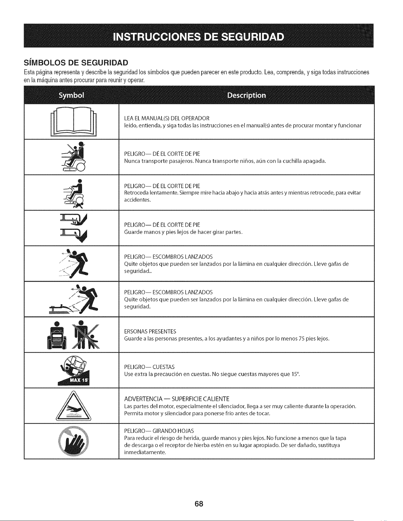
S[IVIBOLOS DE SEGURIDAD
Estap&ginarepresentay describelaseguridadlos simbolosquepuedenpareceren esteproducto.Lea,comprenda,y sigatodas instrucciones
en lam_quinaantesprocurarpara reuniry operar.
i
i
®
J
®
,E,
AL
LEA EL MANUAL(S) DEL OPERADOR
leido, entienda, y siga todas las instrucciones en el manual(s) antes de procurar montar y funcionar
PELIGRO-- DE EL CORTE DE PIE
Nunca transporte pasajeros. Nunca transporte nihos, aun con la cuchilla apagada.
PELIGRO-- DE EL CORTE DE PIE
Retroceda lentamente. Siempre mire hacia abajo y hacia atr_is antes y mientras retrocede, para evitar
accidentes.
PELIGRO-- DE EL CORTE DE PIE
Guarde manos y pies lejos de hacer girar partes.
PELIGRO-- ESCOMBROS LANZADOS
Quite objetos que pueden set lanzados pot la I_imina en cualquier direcci6n. Lleve galas de
seguridad..
PELIGRO-- ESCOMBROS LANZADOS
Quite objetos que pueden set lanzados pot la I_imina en cualquier direcci6n. Lleve galas de
seguridad.
ERSONAS PRESENTES
Guarde a las personas presentes, a los ayudantes y a nihos pot Io menos 75 pies lejos.
PELIGRO-- CUESTAS
Use extra la precauci6n en cuestas. No siegue cuestas mayores que 15°.
ADVERTENCIA-- SUPERFICIE CALIENTE
Las partes del motor, especialmente el silenciador, Ilega a set muy caliente durante la operaci6n.
Permita motor y silenciador para ponerse frio antes de tocar.
PELIGRO-- GIRANDO HOJAS
Para reducir el riesgo de herida, guarde manos y pies lejos. No funcione a menos que la tapa
de descarga o el receptor de hierba est6n en su lugar apropiado. De ser dahado, sustituya
inmediatamente.
68
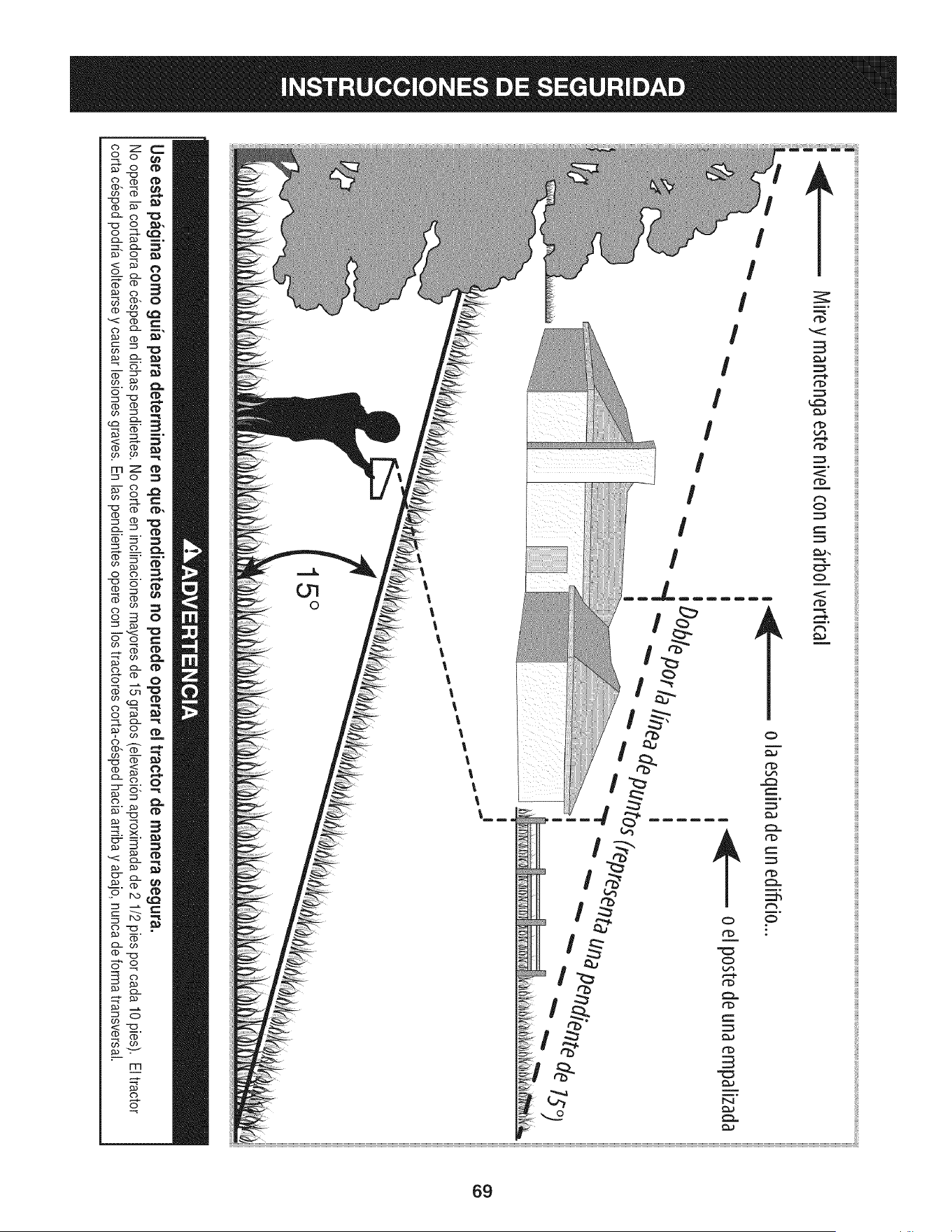
Q_
rT1
(b
(b
rrl
o
69

Estapgtginasemarch6intencionadamenteenblanco.
70
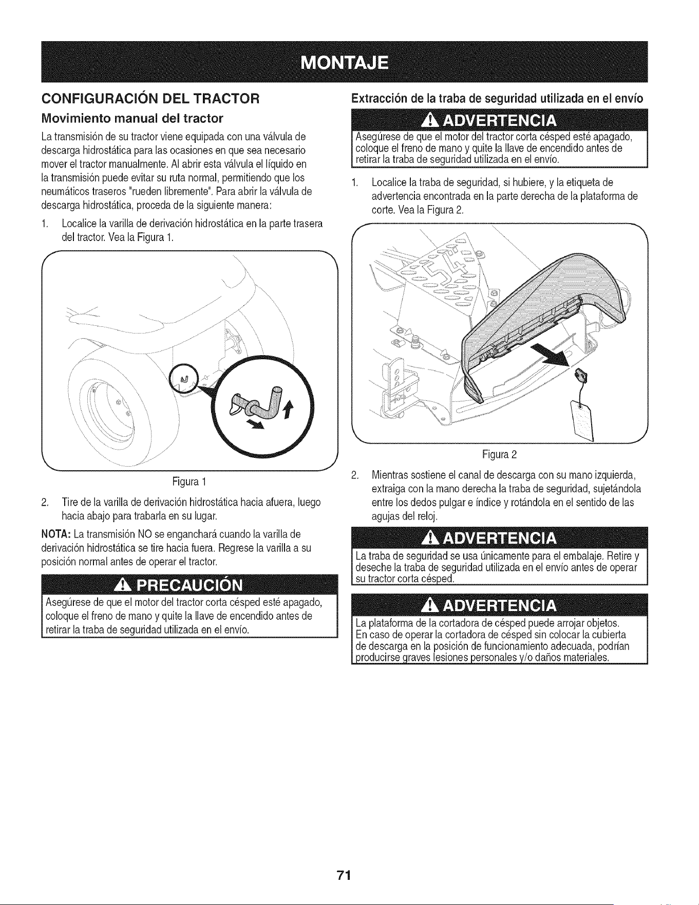
CONFIGURACION DEL TRACTOR
IViovirniento manual del tractor
Latransmisi6nde sutractorvieneequipadacon unav_Jvulade
descargahidrost_.ticapara las ocasionesen queseanecesario
movereltractormanualmente.AIabrirestavAJvulael liquidoen
latransmisi6npuedeevitarsu ruta normal,permitiendoquelos
neum_.ticostraseros"ruedenlibremente".Paraabrir la v_Jvulade
descargahidrost_.tica,procedade la siguientemanera:
1. Localicela varillade derivaci6nhidrost_.ticaen la partetrasera
deltractor.Veala Figura1.
,,,"J/
\
Figura1
2. Tirede lavarillade derivaci6nhidrost_.ticahacia afuera,luego
haciaabajo paratrabarlaen su lugar.
NOTA: La transmisi6nNOse enganchar_,cuandola varillade
derivaci6nhidrost_.ticase tirehaciafuera.Regresela varillaa su
posici6nnormalantesdeoperarel tractor.
AsegQresede queel motordeltractorcorta c_spedest_ apagado,
coloqueel frenode manoy quite la Ilavede encendidoantes de
retirarla trabade seguridadutilizadaenel envio.
Extracci6n de la traba de seguridad utilizada en el envio
AsegQresedequeel motordel tractorcorta c_spedest_ apagado,
coloqueel frenode manoy quitela Ilavedeencendidoantesde
retirarlatraba de seguridadutilizadaen el envio.
1. Localicela trabade seguridad,si hubiere,y la etiquetade
advertenciaencontradaen la partederechade la plataformade
corte.Vea la Figura2.
f x \\
x\ \\
\\
.
Figura2
Mientrassostieneel canalde descargacon su manoizquierda,
extraigacon la manoderechalatrabade seguridad,sujet_.ndola
entre losdedospulgare indicey rot_.ndolaenel sentidode las
agujasdel reloj.
Latrabade seguridadse usa Qnicamenteparael embalaje.Retirey
desechela trabade seguridadutilizadaen el envio antesde operar
su tractorcortacesped.
3roducirsecraveslesiones#ersonalesy/o da_osmateriales.
71
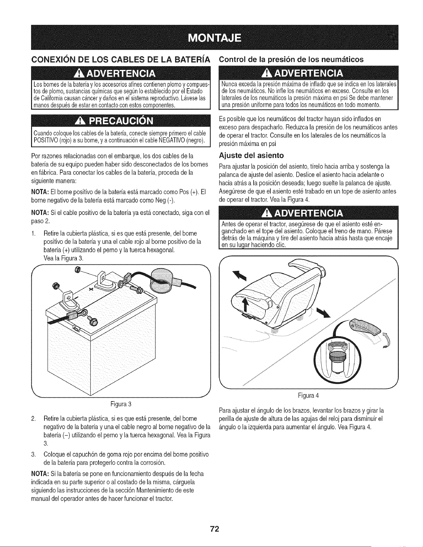
CONEXION DE LOS CABLES DE LA BATERiA Control de la presi6n de los neumaticos
3uesde estarencontactoconestoscomponentes.
Cuandocoloqueloscablesdela bateria,conectesiempreprimeroel cable
POSITIVO(rojo)a suborne,y acontinuaci6nelcableNEGATIVO(negro).
Porrazonesrelacionadasconel ernbarque,los doscablesde la
bateriade su equipopuedenhabersido desconectadosde los bornes
enf_.brica.Paraconectarloscablesdela bateria,procedade la
siguienternanera:
NOTA:El bornepositivode la bateriaest,. rnarcadocornoPos (+). El
bornenegativodela bateriaest,.rnarcadocornoNeg(-).
NOTA:Si el cable positivode labateriayaest,.conectado,siga conel
paso2.
f
Retirela cubiertapl_.stica,si es que est,. presente,del borne
positivode la batefiay unael cable rojoal borne positivode la
bateria(+) utilizandoel pernoy latuercahexagonal.
Veala Figura3.
Nuncaexcedalapresi6nmaximade infladoqueseindicaen loslaterales
delosneum_.ticos.Noinfielosneum_.ticosen exceso.Consulteenlos
lateralesdelos neum_.ticosla presi6nmaximaenpsi Sedebemantener
unapresi6nuniformeparatodoslosneum_.ticosen todomomento.
Esposiblequelos neurn_.ticosde[ tractorhayansidoinfladosen
excesoparadespacharlo.Reduzca[a presi6nde losneurn_.ticosantes
de operarel tractor.Consuiteen los [ateralesde los neurn_.ticos[a
presi6nrn_.xirnaen psi
Ajuste del asiento
Paraajustarla posici6ndel asiento,firelohaciaarribay sostengala
palancadeajustedel asiento.Desliceel asientohaciaadelanteo
haciaatr_.sa la posici6ndeseada;luegosueltela palancadeajuste.
AsegQresedequeel asientoest_trabadoen un topede asientoantes
de operarel tractor.Veala Figura4.
arhaciendoclic.
Figura3
.
Retirela cubiertapl_.stica,si es que est,. presente,del borne
negativode la bateriay una el cable negroal bornenegativode la
bateria(-) utilizandoel pernoy la tuercahexagonal.Veala Figura
3.
3. Coloqueel capuch6nde gornarojo por encirnadel bornepositivo
dela bateriapara protegerlocontrala corrosi6n.
NOTA:Si la bateriase poneen funcionarnientodespu_sde lafecha
indicadaen su partesuperioro alcostadode la rnisrna,c_.rguela
siguiendolas instruccionesde la secci6nMantenirnientode este
manualdeloperadorantesde hacerfuncionarel tractor.
Figura4
Paraajustarel _.ngulode los brazos,levantarlos brazosy girarla
perilladeajustede alturade las agujasdelrelojparadisrninuirel
_.nguloo la izquierdaparaaurnentarel _.ngulo.Vea Figura4.
72
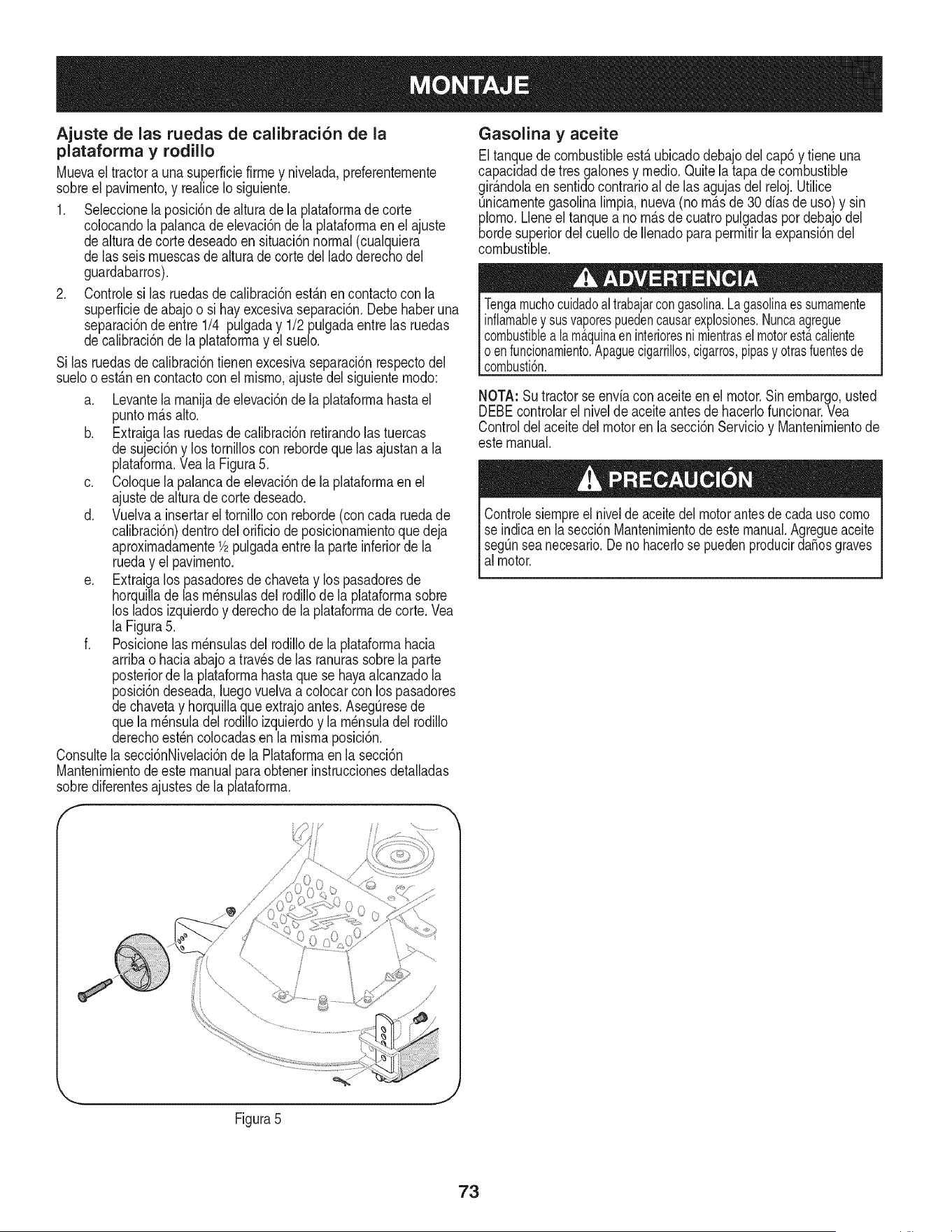
Ajuste de las ruedas de calibraci6n de la
plataforma y rodillo
Muevaeltractora una superficiefirrney nivelada,preferenternente
sobreel pavirnento,y realiceIo siguiente,
1, Selecdonela posicbnde alturade la plataforrnade corte
colocandola palancadeelevad6n de la plataforrnaen el ajuste
dealturade cortedeseadoensituaci6nnormal(cualquiera
de lasseis rnuescasde alturadecortedel ladoderechodel
guardabarros).
2, Controlesi las ruedasde calibraci6nest_.nencontactocon la
superfidedeabajoo si hayexcesivaseparad6n,Debehaberuna
separad6nde entre 1/4 pulgaday 1/2 pulgadaentre las ruedas
decalibraci6nde la plataforrnay el suelo.
Si las ruedasde calibraci6ntienenexcesivaseparaci6nrespectodel
sueloo est_.nen contactocon el rnisrno,ajuste del siguienternodo:
a. Levantela rnanijade elevaci6nde la plataforrnahasta el
puntorn_.salto.
b. Extraigalas ruedasde calibraci6nretirandolastuercas
de sujeci6ny lostornilloscon rebordequelasajustana la
plataforrna.Vea la Figura5.
c. Coloquela palancade elevaci6nde la plataforrnaen el
ajustede alturade corte deseado.
d. Vuelvaa insertarel tornillocon reborde(concada ruedade
calibraci6n)dentrodel orificiode posicionarnientoque deja
aproxirnadarnente1/2pulgadaentrela parteinferiorde la
rueday el pavirnento.
e. Extraigalos pasadoresde chavetay lospasadoresde
horquillade las rn_nsulasdel rodillode la plataforrnasobre
los ladosizquierdoy derechode la plataforrnade corte.Vea
la Figura5.
f. Posicionelas rn_nsulasdel rodillode la plataforrnahacia
arribao haciaabajo a travesde las ranurassobrela parte
posteriorde la plataforrnahastaquese hayaalcanzadola
posici6ndeseada,luegovuelvaacolocarconlos pasadores
dechavetay horquillaqueextrajoantes.AsegQresede
quela rn_nsuladel rodilloizquierdoy la rn_nsuladel rodillo
derechoest_ncolocadasen la rnisrnaposici6n.
Consultela secci6nNivelaci6nde la Plataforrnaen la secci6n
Mantenirnientode este manualparaobtenerinstruccionesdetalladas
sobrediferentesajustesdela plataforrna.
f
i[ \ .............
Gasolina y aceite
Eltanquede combustibleestAubicadodebajodelcap6 y tiene una
capacidadde tresgalonesy rnedio.Quitela tapa decombustible
gir_.ndolaen sentidocontrarioal de las agujasdel reloj.Utilice
Qnicarnentegasolinalirnpia,nueva(no rn_.sde 30 diasde uso)y sin
plorno.Lleneel tanquea no rn_.sde cuatropulgadaspor debajodel
hordesuperiordel cuellode Ilenadopara perrnitirla expansi6ndel
combustible.
Tengamuchocuidadoaltrabajarcongasolina.Lagasolinaessumamente
inflamabley susvaporespuedencausarexplosiones.Nuncaagregue
combustiblea lamAquinaeninterioresnimientrasel motorestacaliente
oenfuncionamiento.Apaguecigarrillos,cigarros,pipasy otrasfuentesde
combusti6n.
NOTA: Su tractorseenvia conaceiteenel motor.Sinembargo,usted
DEBEcontrolarel nivelde aceiteantesde hacerlofuncionar.Vea
Controldelaceitedelmotoren la secci6nServicioy Mantenirnientode
estemanual.
Controlesiempreel nivelde aceitedelmotorantesdecadausocorno
se indicaen la secci6nMantenirnientodeestemanual.Agregueaceite
segunseanecesario.Denohacerlosepuedenproducirda_osgraves
al motor.
Figura5
J
73
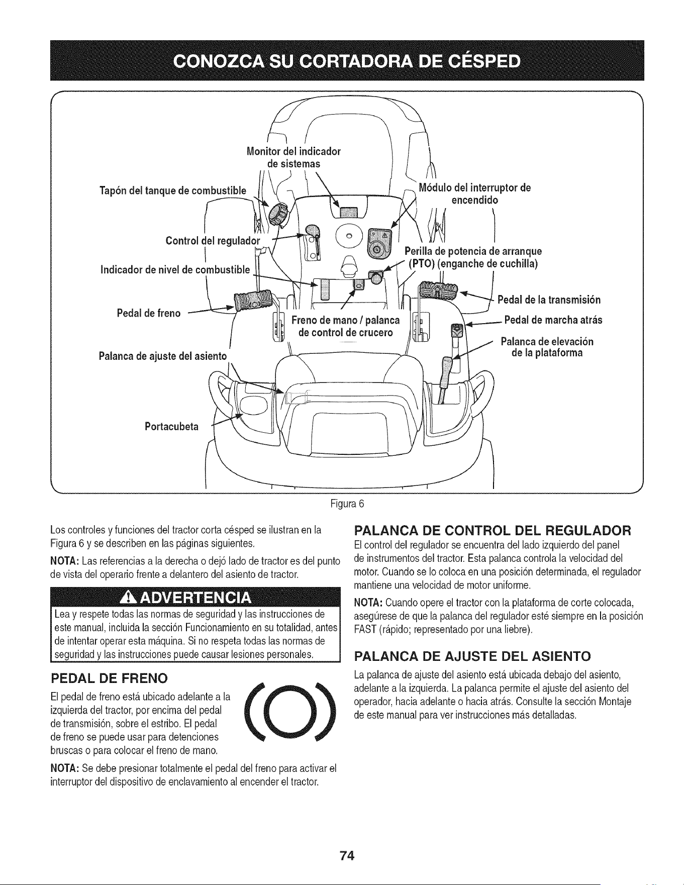
f
Tap6ndel tanque de combustible
Control del reguladc
I
Indicador de nivel de combustible
Monitordel indicador
de sistemas
M6dulodel interruptorde
encendido
Perillade potenciade arranque
(PTO)(enganche de cuchilla)
Pedalde freno
Palancade ajuste del asiento
Freno de mano/ palanca
decontrolde crucero
Pedalde la transmisi6n
Pedalde marcha atr_s
Palancade elevaci6n
de la plataforma
Portacubeta
\
Figura6
Loscontrolesy funcionesdel tractorcortacesped se ilustranen la
Figura6 y se describenen lasp_.ginassiguientes.
NOTA:Las referenciasa laderechao dej6 lado de tractores del punto
devista del operariofrentea delanterodel asientode tractor.
Leay respetetodaslas normasde seguridady las instruccionesde I
estemanual,incluidala secci6nFuncionarnientoensu totalidad,antesI
de intentaroperarestam_.quina.Si no respetatodaslasnormasde
segurdady as nstrucconespuedecausar es onespersonaes. I
PEDAL DE FRENO
Elpedaldefrenoest,. ubicadoadelantea la
izquierdadel tractor,por encimadelpedal
detransmisi6n,sobreel estribo.Elpedal
defreno se puedeusarpara detenciones
bruscaso paracolocarelfreno de mano.
NOTA:Se debe presionartotalmenteel pedal del frenoparaactivarel
interruptordel dispositivodeenclavamientoalencenderel tractor.
PALANCA DE CONTROL DEL REGULADOR
Elcontroldel reguladorseencuentradel lado izquierdodel panel
de instrumentosdel tractor.Estapalancacontrolala velocidaddel
motor.Cuandose Iocolocaenunaposici6ndeterminada,el regulador
mantieneunavelocidadde motoruniforme.
NOTA:Cuandoopereel tractorcon la plataformadecortecolocada,
asegQresede quela palancadel reguladorest_ siempreen la posici6n
FAST(r_.pido;representadoporunaliebre).
PALANCA DE AJUSTE DEL ASIENTO
Lapalancade ajustedel asientoest,. ubicadadebajodel asiento,
adelantea la izquierda.Lapalancapermiteel ajustedel asientodel
operador,haciaadelanteo haciaatr_.s.Consultela secci6nMontaje
de estemanualpara vet instruccionesm_.sdetalladas.
74
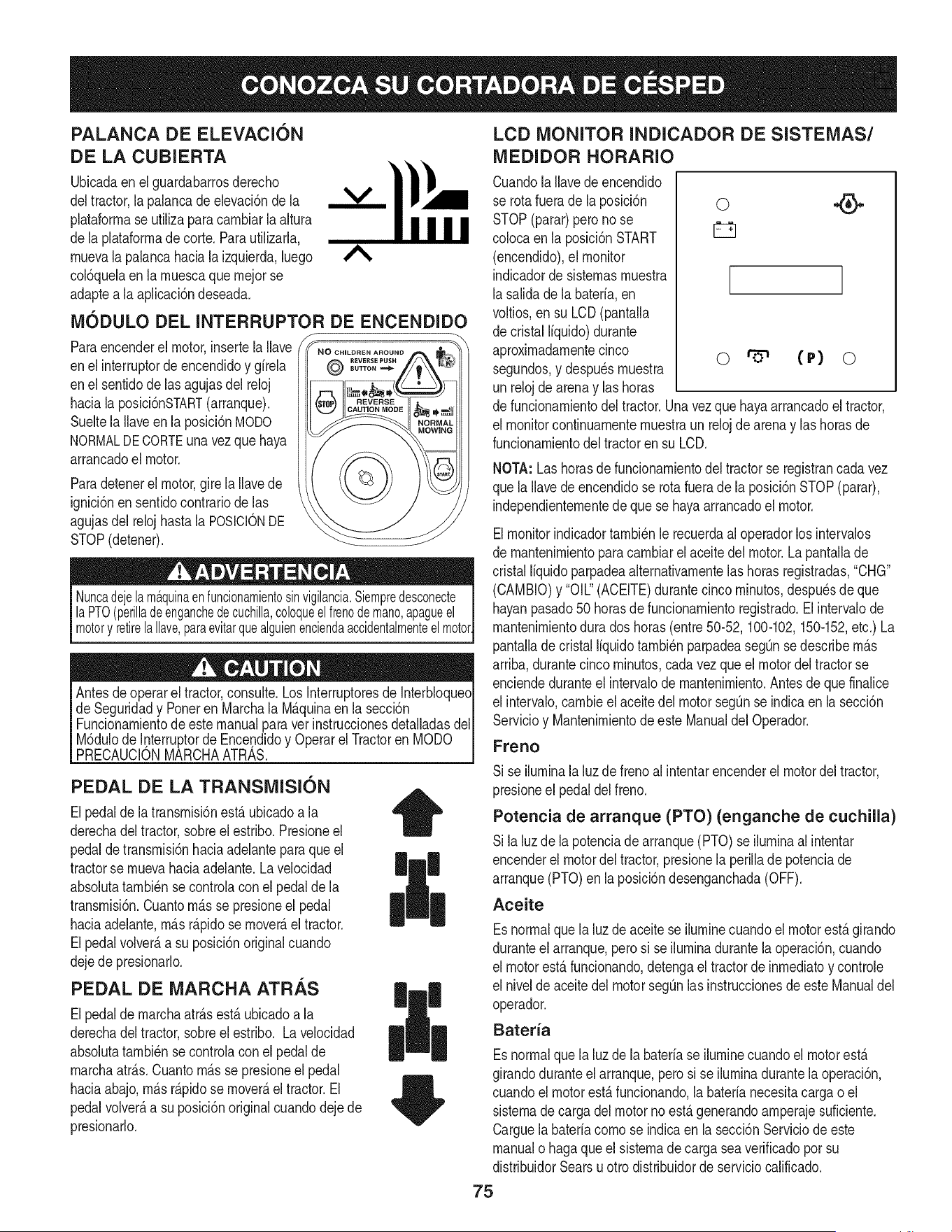
PALANCA DE ELEVACI6N
DE LA CUBIERTA
Ubicadaenel guardabarrosderecho i
deltractor,la palancade elevaci6nde la V
plataforrnase utiNzaparacarnbiarla altura
dela plataforrnade corte.ParautiNzarla,
rnuevalapalancahaciala izquierda,luego
col6quelaenla rnuescaquernejorse
adaptea la apNcaci6ndeseada.
M6DULO DEL INTERRUPTOR DE ENCENDIDO
Paraencenderel motor,insertela Nave
enel interruptordeencendidoy gfrela
enel sentidode lasagujasdel reloj
haciala posici6nSTART(arranque).
Sueltela Naveen la posici6nMODO
NORMALDECORTEunavezque haya
arrancadoel motor.
Paradetenerel motor,gire la Navede
ignici6nen sentidocontrariode las
agujasdel relojhastala POSlCIONDE
STOP(detener).
_NO CHILDREN AROUND
d
Nuncadejelam_.quinaenfuncionamientosinvigilancia.Siempredesconecte
laPTO(perilladeenganchedecuchilla,coloqueelfrenode mano,apagueel
motory retirela Ilave,paraevitarquealguienenciendaaccidentalmenteelmotor.
Antesdeoperarel tractor,consulte.Los Interruptoresde InterbloqueoI
de Seguridady Poneren Marchala M_.quinaenla secci6n I
Funcionarnientode este manualpara ver instruccionesdetalladasdelI
M6dulode Interruptorde Encendidoy Operarel Tractoren MODO
PRECAUCON MARCHAATRAS. I
PEDAL DE LA TRANSMISI6N
Elpedalde latransrnisi6nest,.ubicadoa la
derechadeltractor,sobreel estribo.Presioneel
pedalde transrnisi6nhaciaadelanteparaque el
tractorse rnuevahaciaadelante.La velocidad
absolutatarnbi@nse controlaconel pedal dela
transrnisi6n.Cuantorn_.sse presioneel pedal
haciaadelante,rn_.sr@idose rnover_,el tractor.
Elpedalvolver_,a su posici6noriginalcuando
dejedepresionarlo.
PEDAL DE MARCHA ATRAS
Elpedalde rnarchaatr_.sest,.ubicadoa la
derechadeltractor,sobreel estribo. La velocidad
absolutatarnbi_nse controlaconel pedalde
rnarchaatr_.s.Cuantorn_.sse presioneel pedal
haciaabajo,rn_.sr@idose rnover_,el tractor.El
pedalvolver_,a su posici6noriginalcuandodeje de
presionarlo.
II
II
LCD MONITOR INDICADOR DE SISTEMAS/
MEDIDOR HORARIO
CuandolaNavede encendido
se rotafuerade laposici6n
STOP(parar)peronose
colocaenla posici6nSTART
(encendido),el monitor
indicadorde sisternasrnuestra
lasalidade la baterfa,en
voltios,en su LCD(pantalla
de cristalIfquido)durante
aproxirnadarnentecinco
segundos,y despu_srnuestra
unrelojdearenay las horas
o
o (P) o
de funcionarnientodel tractor.Unavezquehayaarrancadoel tractor,
el monitorcontinuarnenternuestraun relojdearenay las horasde
funcionarnientodel tractorensu LCD.
NOTA:Lashorasde funcionarnientodeltractorse registrancada vez
que laNavede encendidose rotafueradela posici6nSTOP(parar),
independienternentede que se hayaarrancadoel motor.
Elmonitorindicadortarnbi_nle recuerdaal operadorlos intervalos
de rnantenirnientoparacarnbiarelaceitedelmotor.La pantallade
cristal Ifquidoparpadeaalternativarnentelas horasregistradas,"CHG"
(CAMBIO)y "OIL"(ACEITE)durantecincorninutos,despu_sde que
hayanpasado50 horasde funcionarnientoregistrado.Elintervalode
rnantenirnientodurados horas(entre50-52,100-102,150-152,etc.) La
pantaNadecristalIfquidotarnbi_nparpadeaseg_nsedescribern_.s
arriba,durantecinco rninutos,cada vezque elmotordel tractorse
enciendeduranteel intervalode mantenirniento.Antesdeque finance
el intervalo,carnbieelaceitedelmotorsegOnse indicaen la secci6n
Servicioy Mantenirnientode este Manualdel Operador.
Freno
Sise ilurninala luz defrenoal intentarencenderel motordel tractor,
presioneel pedaldelfreno.
Potencia de arranque (PTO) (enganche de cuchilla)
Sila luzde la potenciade arranque(PTO)se ilurninaal intentar
encenderel motordeltractor,presionela perillade potenciade
arranque(PTO)en la posici6ndesenganchada(OFF).
Aceite
Esnormalquela luzde aceitese ilurninecuandoel motorest,. girando
duranteel arranque,pero si se ilurninadurantelaoperaci6n,cuando
el motorest,.funcionando,detengael tractorde inrnediatoy controle
el nivelde aceitedel motorsegOnlasinstruccionesde este Manualdel
operador.
Bateria
Esnormalquela luzde la baterfase ilurninecuandoel motorest,.
girandoduranteel arranque,pero si se ilurninadurantela operaci6n,
cuandoel motorest,. funcionando,la baterfanecesitacargao el
sisternade cargadel motorno est,.generandoarnperajesuficiente.
Carguelabaterfacornose indicaen la secci6nServiciode este
manualo hagaqueel sisternade cargasea verificadopot su
distribuidorSearsu ottodistribuidorde serviciocalificado.
75
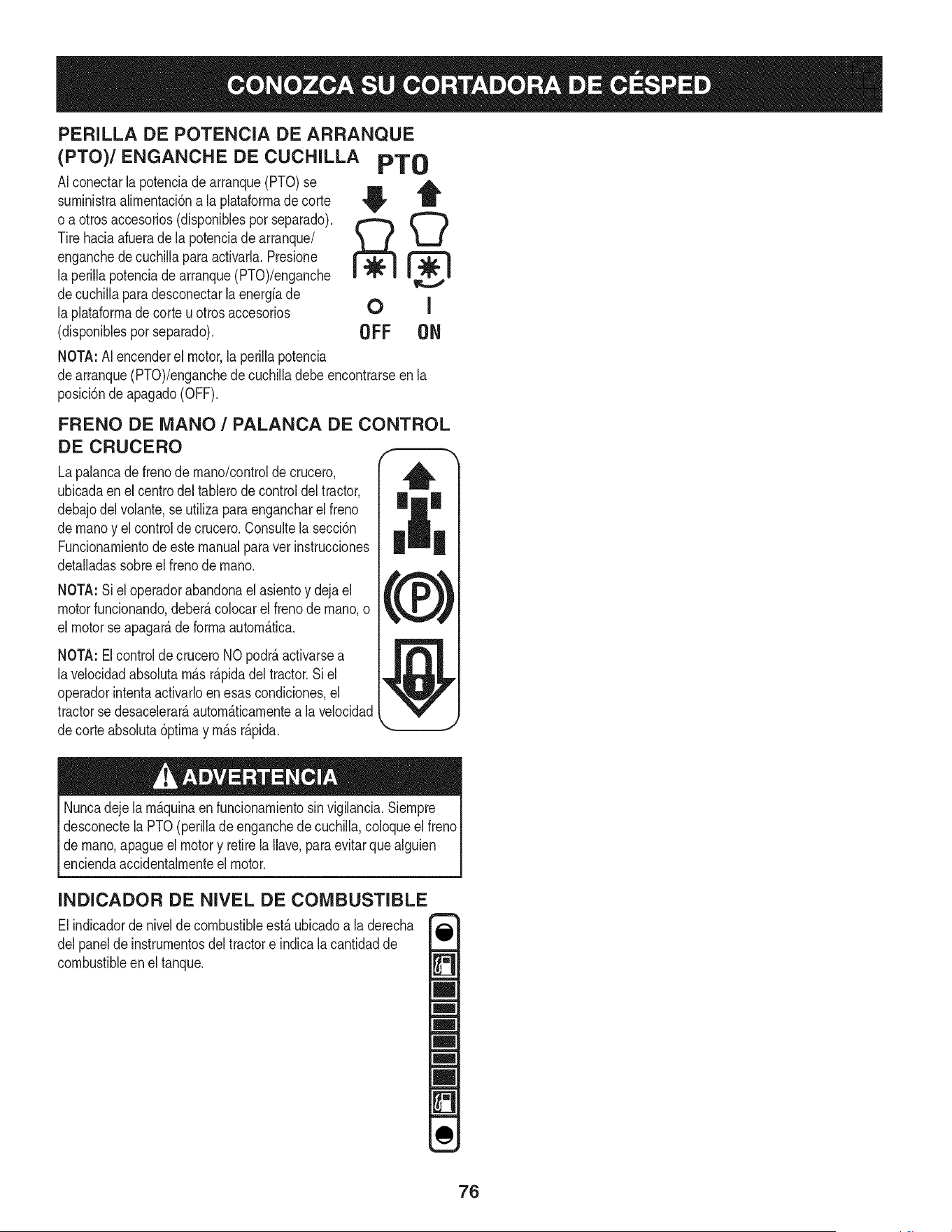
PERILLA DE POTENCIA DE ARRANQUE
(PTO)/ENGANCHE DE CUCHILLA PTO
AIconectarla potenciadearranque(PTO)se
surninistraalirnentaci6nala plataforrnade corte
o aotrosaccesorios(disponiblesporseparado).
Tire haciaafuerade lapotenciadearranque/
enganchede cuchillapara activada.Presione
la perillapotenciade arranque(PTO)/enganche
decuchillaparadesconectarla energfade
la plataforrnadecorteu otrosaccesorios
(disponiblesporseparado). OFF ON
NOTA:AI encenderel motor,la perillapotencia
dearranque(PTO)/enganchede cuchilladebeencontrarseen la
posici6ndeapagado(OFF).
FRENO DE MANO / PALANCA DE CONTROL
DE CRUCERO
Lapalancade frenode rnano/controlde crucero,
ubicadaen elcentrodeltablerodecontroldeltractor,
debajodelvolante,se utilizaparaengancharelfreno
dernanoy elcontrolde crucero.Consultela secci6n
Funcionarnientode este manualparavet instrucciones
detalladassobreel frenode rnano.
NOTA:Si el operadorabandonael asientoy deja el
motorfuncionando,deber&colocarel frenode rnano,o
el motorse apagar&de forrnaautorn&tica.
NOTA: Elcontrol de crucero NOpodr&activarsea
lavelocidadabsolutarn&sr&pidadel tractor.Si el
operadorintentaactivarloen esascondiciones,el
tractorsedesacelerar&autorn_.ticarnentea la velocidad
decorteabsoluta6ptirnay rn&sr&pida.
Nuncadejela rn&quinaen funcionarnientosinvigilancia.Siernpre
desconectela PTO(perillade enganchedecuchilla,coloqueel freno
dernano,apagueel motory retirela Ilave,para evitarquealguien
enciendaaccidentalrnenteel motor.
INDICADOR DE NIVEL DE COMBUSTIBLE
El indicadorde nivelde combustibleest_ ubicadoa la derecha
delpanelde instrurnentosdeltractore indicalacantidadde
combustibleen eltanque.
76
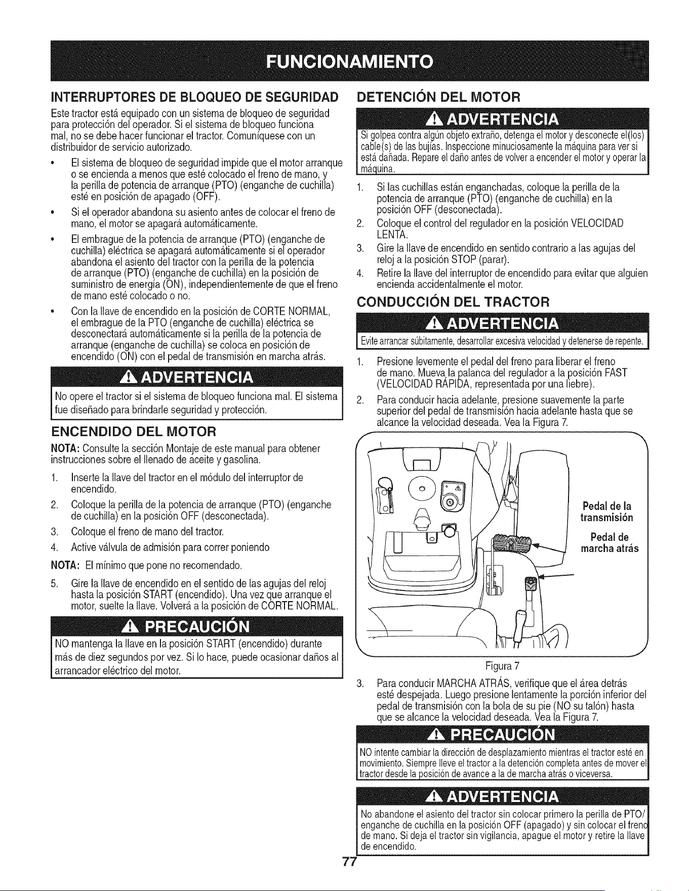
INTERRUPTORES DE BLOQUEO DE SEGURIDAD
Estetractorest,. equipadocon un sisternade bloqueode seguridad
paraprotecci6ndeloperador.Siel sisternadebloqueofunciona
rnal,no se debehacerfuncionarel tractor.Cornuniquesecon un
distribuidordeservicioautorizado.
• Elsisternade bloqueode seguridadirnpideque el motorarranque
o se enciendaa rnenosque est_colocadoel frenodernano,y
la perillade potenciadearranque(PTO)(enganchede cuchilla)
est_enposici6ndeapagado(OFF).
• Siel operadorabandonasu asientoantesdecolocarel frenode
rnano,el motorse apagar_,autorn_.ticarnente.
• Elernbraguede la potenciade arranque(PTO)(enganchede
cuchilla)el_ctricase apagar_,autorn_.ticarnentesi el operador
abandonael asientodel tractorconla perillade la potencia
dearranque(PTO)(enganchede cuchilla)en la posici6nde
surninistrodeenergia(ON), independienternentedequeel freno
dernanoest_colocadoo no.
Conla Ilavede encendidoen la posici6nde CORTENORMAL,
el ernbraguede la PTO(enganchedecuchilla)el_ctricase
desconectar_,autorn_.ticarnentesi la perillade lapotenciade
arranque(enganchedecuchilla)se coloca en posici6nde
encendido(ON)con el pedalde transrnisi6nen rnarchaatr_.s.
Noopere el tractorsiel sisternade bloqueofuncionarnal.El sisterna
ruedise_adopara brindarleseguridady protecci6n.
ENCENDIDO DEL MOTOR
NOTA:Consultela secci6nMontajedeestemanualparaobtener
instruccionessobreel Ilenadode aceitey gasolina.
1. Insertela Ilavedel tractorenel rn6dulodel interruptorde
encendido.
2. Coloquela perillade la potenciade arranque(PTO)(enganche
decuchilla)en laposici6nOFF(desconectada).
3. Coloqueel frenodernanodel tractor.
4. Activev_.lvulade adrnisi6nparacorrerponiendo
NOTA: Elrninirnoqueponenorecornendado.
5. Gire la Ilavede encendidoen el sentidode las agujasdel reloj
hastala posici6nSTART(encendido).Unavezque arranqueel
motor,sueltela Ilave.Volver_.a laposici6nde CORTENORMAL.
NOrnantengala Ilaveen la posici6nSTART(encendido)durante
rn_.sde diez segundospor vez.Si Iohace,puedeocasionarda_osal
arrancadorel_ctricodel motor.
DETENCION DEL MOTOR
Jina.
1. Si las cuchillasest_.nenganchadas,coloquela perillade la
potenciadearranque(PTO)(enganchede cuchilla)en la
posicidnOFF(desconectada).
2. Coloqueel controldel reguladoren la posicidnVELOCIDAD
LENTA.
3. Girela Ilavede encendidoen sentidocontrarioalas agujasdel
reloja la posicidnSTOP(parar).
4. RetirelaIlavedel interruptorde encendidoparaevitar que alguien
enciendaaccidentalrnenteel motor.
CONDUCCION DEL TRACTOR
77
EvitearrancarsObitamente,desarrollarexcesivavelocidadydetenersederepente.
Presionelevernenteel pedaldel frenopara liberarel freno
de rnano.Muevala palancadel reguladora la posici6nFAST
(VELOCIDADRAPIDA,representadaporunaliebre).
Paraconducirhaciaadelante,presionesuavernentelaparte
superiordel pedalde transrnisi6nhaciaadelantehastaque se
alcancelavelocidaddeseada.Veala Figura7.
f
Pedalde la
[ _ i transrnisidn
\
J
Figura7
3. ParaconducirMARCHAATRAS,verifiqueque el _.readetr_.s
est_despejada.Luegopresionelentarnentela porci6ninferiordel
pedaldetransrnisi6ncon la bolade su pie(NO su tal6n)hasta
que sealcancela velocidaddeseada.Vea la Figura7.
NOintentecambiarladirecci6ndedesplazamientomientrasel tractoresteen
movimiento.SiempreIleveeltractora la detenci6ncompletaantesde moverel
|tractordesdeaposc 6ndeavancea ademarchaatra.sovceversa.
__) y sin colocar el frenc_
de mano_or y retire la Ilave I
de encendido.
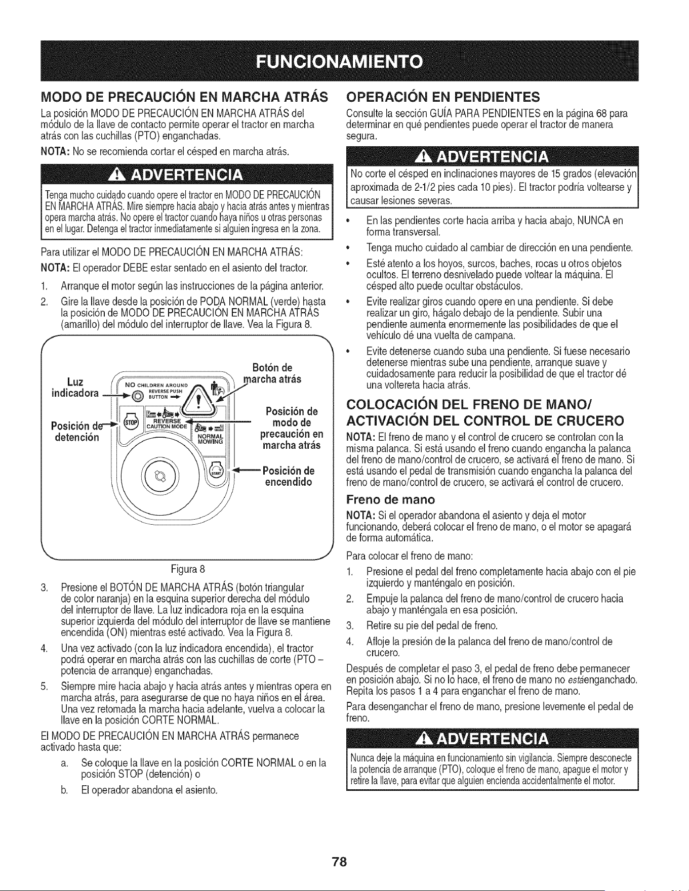
iVlODO DE PRECAUClON EN MARCHA ATRAS
La posici6nMODODE PRECAUCIONENMARCHAATRASdel
rn6dulode la Ilavede contactoperrniteoperarel tractoren rnarcha
atr_.scon las cuchillas(PTO)enganchadas.
NOTA: Nose recorniendacortarel cespeden rnarchaatr_.s.
TengamuchocuidadocuandoopereeltractorenMODODEPRECAUCION
ENMARCHAATRAS.Miresiemprehaciaabajoy haciaatra.santesy mientras
operamarchaatra.s.NoopereeltractorcuandohayaniSosuotraspersonas
l ene ugar.Detengae tractornmedatamentes aguen ngresaen azona.
Parautilizarel MODODEPRECAUCIONENMARCHAATRAS:
NOTA: EloperadorDEBEestar sentadoen el asientodel tractor.
.
2.
Arranqueel motorsegOnlas instruccionesde la p_.ginaanterior.
GirelaIlavedesdela posici6nde POD,A NORMAL(verde)hasta
la posicidnde MODODE PRECAUCIONEN MARCHAATRAS
(amarillo)delrn6dulodel interruptordeIlave.Veala Figura8.
f
Luz
indicadora
Bot6n de
rnarchaatr_s
detenci6n
Posici6n de
rnodode
preeaucibnen
mareha atr_s
encendido
Figura8
3. Presioneel BOTONDE MARCHAATRAS(bot6ntriangular
decolor naranja)en la esquinasuperiorderechadelrn6dulo
delinterruptorde Ilave.Laluz indicadorarojaen la esquina
superiorizquierdadelrn6dulodel interruptorde Ilavese rnantiene
encendida(ON)rnientrasest_ activado.Vea la Figura8.
4. Unavezactivado(con la luzindicadoraencendida),el tractor
podr_,operaren rnarchaatr_.scon las cuchillasde corte(PTO-
potenciade arranque)enganchadas.
5. Siernpremirehaciaabajoy haciaatr_.santesy rnientrasopera en
rnarchaatr_.s,paraasegurarsedeque nohayaniffosenel _.rea.
Unavez retornadala rnarchahaciaadelante,vuelvaa colocarla
Ilaveenla posicidnCORTENORMAL.
El MODODEPRECAUCIONENMARCHAATRASperrnanece
activadohastaque:
a. Se coloquelaNaveen laposici6nCORTENORMALo enla
posici6nSTOP(detencidn)o
b. El operadorabandonael asiento.
OPERACI6N EN PENDIENTES
Consultela secci6nGU{APARAPENDIENTESen la p_.gina68 para
deterrninarenqu_ pendientespuedeoperareltractorde rnanera
segura.
Nocorte el cespeden inclinacionesrnayoresde 15grados(elevaci6n
aproxirnadade 2-1/2piescada 10pies).Eltractorpodrfavoltearsey
causarlesionesseveras.
,, Enlas pendientescorte haciaarribay haciaabajo,NUNCAen
forrnatransversal.
,, Tengarnuchocuidadoalcarnbiarde direcci6nen unapendiente.
,, Esteatentoa los hoyos,surcos,baches,rocasuotrosobjetos
ocultos.El terrenodesniveladopuedevoltearlarn_.quina.El
c_spedalto puedeocultarobst_.culos.
,, Eviterealizargiroscuandoopereen una pendiente.Si debe
realizarungiro,h_.galodebajode la pendiente.Subiruna
pendienteaurnentaenorrnernentelasposibilidadesdequeel
vehfculod_ unavueltadecarnpana.
,, Evitedetenersecuandosuba unapendiente.Si fuesenecesario
detenersernientrassube una pendiente,arranquesuavey
cuidadosarnentepara reducirla posibiNdadde que el tractord_
unavolteretahaciaatr_.s.
COLOCACI6N DEL FRENO DE iVlANO/
ACTIVACI6N DEL CONTROL DE CRUCERO
NOTA: El frenode rnanoy elcontroldecrucerose controlancon la
rnisrnapalanca.Siest,.usandoel frenocuandoenganchala palanca
del frenode rnano/controlde crucero,se activate,elfrenode rnano.Si
est,.usandoel pedalde transrnisi6ncuandoenganchala palancadel
frenode rnano/controlde crucero,se activate,el controlde crucero.
Freno de rnano
NOTA: Si el operadorabandonael asientoy dejael motor
funcionando,deber_,colocarel frenode rnano,o el motorse apagar_.
de forrnaautorn_.tica.
Paracolocarel frenode rnano:
1. Presioneel pedaldel frenocornpletarnentehaciaabajocon el pie
izquierdoy rnant_ngaloen posici6n.
2. Ernpujela palancadelfrenode rnano/controlde crucerohacia
abajoy rnant_ngalaen esa posici6n.
3. Retiresu piedelpedaldefreno.
4. Aflojela presi6nde la palancadelfrenode rnano/controlde
crucero.
Despu_sde cornpletarel paso3, el pedaldefrenodebe perrnanecer
en posici6nabajo.Si no Io hace,el frenode rnanono estbenganchado.
Repitalos pasos1 a 4 para engancharel frenode rnano.
Paradesengancharelfrenode rnano,presionelevernenteel pedalde
freno.
Nuncadejelama.quinaenfuncionamientosinvigilancia.Siempredesconecte
lapotenciadearranque(PTO),coloqueel frenodemano,apagueel motory
retirelaNave,paraevitarquealguienenciendaaccidentalmenteelmotor.
78
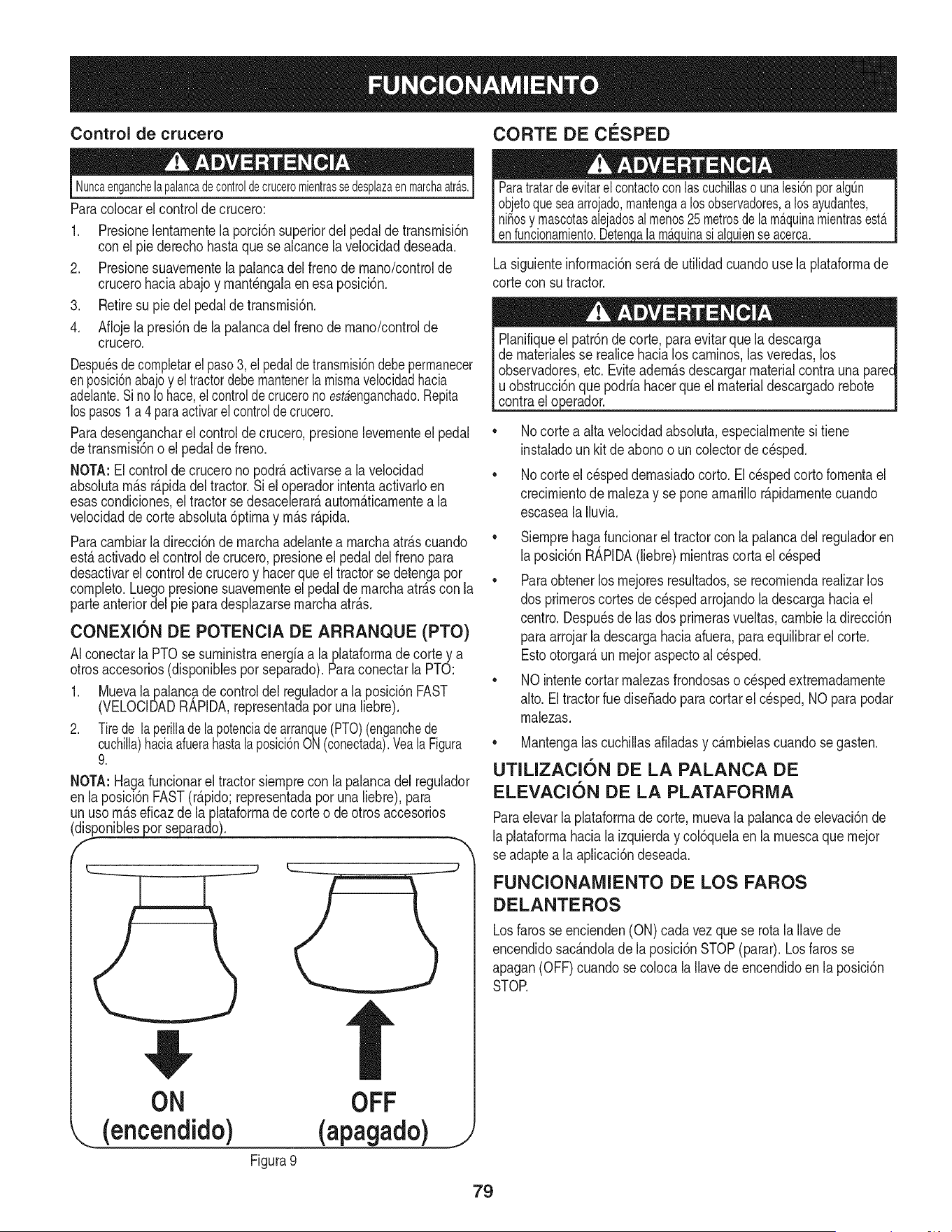
Control de crucero CORTE DE CF:SPED
Nuncaenganchelapalancadecontroldecruceromientrassedesplazaenmarchaatras.
Paracolocarel controlde crucero:
1. Presionelentarnentela porci6nsuperiordel pedalde transrnisi6n
conel pie derechohastaque se alcancela velocidaddeseada.
2. Presionesuavernentelapalancadel frenode rnano/controide
crucerohaciaabajoy rnant_ngaiaenesa posici6n.
3. Retiresu piedel pedalde transrnisi6n.
4. Aflojela presi6nde lapaiancadel frenode rnano/controide
crucero.
Despu_sdecompletarelpaso3, elpedaldetransmisi6ndebepermanecer
enposici6nabajoy el tractordebemantenerla mismavelocidadhacia
adelante.SinoIohace,el controlde crucerono estaenganchado.Repita
lospasos1 a 4 paraactivarel controlde crucero.
Paradesengancharel controldecrucero,presionelevernenteel pedal
detransrnisi6no el pedaldefreno.
NOTA:El controlde crucerono podr_,activarsea la velocidad
absolutarn_.sr_.pidadel tractor.Si el operadorintentaactivarloen
esascondiciones,el tractorsedesacelerar_,autorn_.ticarnentea la
velocidadde corteabsoluta6ptirnay rn_.sr_.pida.
Paracarnbiarla direcci6nde rnarchaadeiantea rnarchaatr_.scuando
est,.activadoel control de crucero,presioneel pedaldel frenopara
desactivarelcontrolde cruceroy hacerqueel tractorse detengapor
cornpleto.Luegopresionesuavernenteel pedalde rnarchaatr_.scon la
parteanteriordel pie para desplazarsernarchaatr_.s.
CONEXI(SN DE POTENCIA DE ARRANQUE (PTO)
AIconectarla PTOsesurninistraenergiaa la plataforrnade corte y a
otrosaccesorios(disponiblesporseparado).Paraconectarla PTO:
1. Muevalapalancadecontroldel reguladora laposici6nFAST
(VELOCIDADRAPIDA,representadaporunaliebre).
2. Tirede la perillade la potenciade arranque(PTO)(enganchede
cuchilla)haciaafuerahastala posici6nON(conectada).VealaFigura
9.
NOTA:Hagafuncionarel tractorsiernpreconla palancadel regulador
enla posici6nFAST(r_.pido;representadaporunaliebre),para
unuso rn_.seficazdela plataforrnadecorteo de otrosaccesorios
(tponibles porseparado).
ON
(encendido)
Figura 9
OFF
(apagado)
J
enfuncionamiento.Detem ulense acerca.
Lasiguienteinforrnaci6nser_.de utilidadcuandouse la plataforrnade
cortecon su tractor.
Planifiqueelpatr6nde corte, paraevitarque ladescarga
de rnateriaiesse reaiicehacialoscarninos,las veredas,los
observadores,etc. Eviteadern_.sdescargarmaterialcontra una parec
u obstrucci6nquepodriahacerque el materialdescargadorebote
contrael o[oerador.
,, Nocortea altavelocidadabsoluta,especialrnentesi tiene
instaladounkit deabonooun colectorde cesped.
• Nocorte el cespeddernasiadocorto.Elc_spedcortofornentael
crecirnientodernalezay se poneamarillor_.pidarnentecuando
escaseala Iluvia.
,, Siernprehagafuncionarel tractorcon la palancadel reguladoren
laposici6nR_,PIDA(liebre)rnientrascortaelcesped
,, Paraobtenerlos rnejoresresultados,se recorniendarealizarlos
dos prirneroscortesde c_spedarrojandola descargahaciael
centro.Despuesde las dos prirnerasvueltas,carnbiela direcci6n
paraarrojarla descargahaciaafuera,para equilibrarel corte.
Estootorgar_,un rnejoraspectoal cesped.
,, NOintentecortarrnaiezasfrondosaso cespedextrernadarnente
alto.Eltractorrue dise_adopara cortarel cesped,NOpara podar
rnalezas.
,, Mantengalas cuchillasafiladasy c_.rnbielascuandosegasten.
UTILIZACI(SN DE LA PALANCA DE
ELEVACION DE LA PLATAFORIVIA
Paraelevarla plataforrnade corte,rnuevala palancade elevaci6nde
laplataforrnahacia la izquierday col6quelaen larnuescaque rnejor
seadaptea laaplicaci6ndeseada.
FUNCIONAMIENTO DE LOS FAROS
DELANTEROS
Losfaros seencienden(ON) cadavezquese rota laIlavede
encendidosac_.ndolade laposici6nSTOP(parar).Losfarosse
apagan(OFF)cuandose coiocalaIlavede encendidoen la posici6n
STOP.
79
Antesderealizarcualquiertipode rnantenirnientoo servicio,
desenganchetodosloscontroiesy detengaei motor.Esperea quese
detengancornpletarnentetodaslaspiezasrn6viles.Desconecteelcable
delabujiay p6ngalohaciendornasacontrael motorparaevitarque se
enciendaaccidentalrnente.Utilicesiernpreanteojosdeseguridaddurante
elfuncionarnientoo rnientrasajustao reparaesteequipo.
Antesde cadauso 1. Nivelde aceitedel motor
2. Areadel silenciadory
controles
1. Aceitedei motor
Sigaei cronograrnadernantenirnientoque se presentaa continuaci6n.
Estatabla s61odescribepautasde servicio.Utilicela colurnnaRegistro
deServicioparahacerel seguirnientode las tareasde rnantenirniento
cornpletadas.Paraubicar el Centro de Servicio Sears m_s cercano
o paraprograrnarun servicio,sirnplementecomuniquese con
Sears al tel_fono 1-800-4-MY-HOME®.
1. Verificar
2. Lirnpiar
Durantelasprirneras 1. Carnbiar
cincohoras
Cada 10horas 1.
Cada25 horas
Respiraderosdel cap6/
tabierode instrurnentos
2. Bornes
3. Husillosyrn_nsula
interrnediadela plataforrna
1. Prefiltrodel filtro de aire*
2. Filtrode aire*
3. Brazosdemandointermedios,
ejesdelpivotey ejes
4. Rodarnientosdelasruedas
deianteras
5. Ruedasdelanterasdela
plataforrna
1. Aceitedel motor
2. Silenciador
1. Filtrodeaire
2. Prefiltrodel filtro de aire
3. Bujiadeencendido
4. Sisternadeenfriarniento*
5. Filtrode combustible
6. Engranajesdeladirecci6n
7. Ruedastraseras
1. Respiraderosdelcap6/
tablerode instrurnentos
2. Bornes
3. Brazosde rnando
interrnedios,ejesdel pivote
y ejes
4. Rodarnientosdelasruedas
deianteras
5. Ruedasdelanterasdela
piataforrna
6. Husillosyrn_nsula
interrnediadela plataforrna
7. Puntosde pivotedel pedal
1. Lirnpiar
2. Lirnpiar
3. Lubricar
1. Lirnpiar
2. Lirnpiar
3.
4. Lubricar
Lubricar
5. Lubricar
Cada50 horas Carnbiar
Verificar
Anualrnente
Antesde airnacenar
.
2.
1.
2.
3.
4.
5.
6.
7.
1.
2.
3.
4.
,
6.
7.
Reernplazar
Reernplazar
Reernplazar
Lirnpiar
Reernplazar
Lirnpiar
Sacarlos ejesy engrasarlos
Lirnpiar
Lirnpiar
Lubricar
Lubricar
Lubricar
Lubricar
Lubricar
*Reaiiceel serviciorn_.sfrecuenternentecuandohayarn_.spoivo.
Antesde realizartareasdernantenirnientoo reparaciones,
desconectela PTO(palancade enganchede cuchillas),coloque
el frenode rnano,apagueel motory retirela Ilaveparaevitarel
encendidoaccidentaldel motor.
8O
Siel motorse ha puestoen funcionarnientorecienternente,ei motor,
siienciadory lassuperficiesrnet_.licascircundantesestar_.ncalientes
y puedencausarquernadurasen la piel.Tengaprecauci6npara
evitarquernaduras.
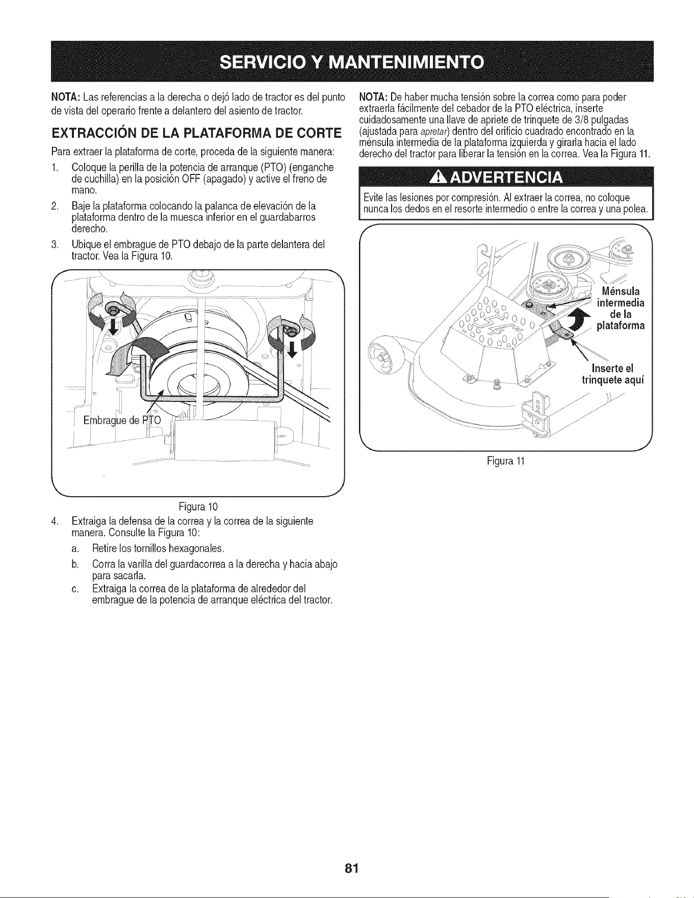
NOTA:Lasreferenciasaladerechaodej6ladodetractoresdeipunto
devistadeloperariofrenteadelanterodelasientodetractor.
EXTRACClON DE LA PLATAFORMA DE CORTE
Paraextraerla plataformade corte,procedade la siguientemanera:
1. Coloquela perillade la potenciade arranque(PTO)(enganche
decuchilla)en laposicbn OFF(apagado)y activeel frenode
mano.
.
.
Bajelaplataformacolocandola palancade elevaci6nde la
plataformadentrode la muescainferiorenel guardabarros
derecho.
Ubiqueel embraguede PTOdebajode la partedelanteradel
tractor.Veala Figura10.
NOT.&:De habermuchatensi6nsobrela correacomoparapoder
extraerlaf&cilmentedelcebadordela PTOelectrica,inserte
cuidadosamenteunaIlavede aprietede trinquetede 3/8 pulgadas
(ajustadaparaapretar)dentrodelorificiocuadradoencontradoen la
mensulaintermediade laplataformaizquierday girarlahaciael lado
derechodeltractorparaliberarla tensi6nen lacorrea.Veala Figura11.
Evitelas lesionespor compresi6n.AIextraerla correa,no coloque
nuncalos dedosen el resorteintermedioo entrelacorreay unapolea.
//
//
/'
M_nsula
intermedia
de la
plataforma
Inserte el
trinquete aqui
Figura11
.
Figura10
Extraigaladefensade lacorreay la correadela siguiente
manera.Consultela Figura10:
a. Retirelos tornilloshexagonales.
b. Corralavarilladel guardacorreaa la derechay haciaabajo
parasacarla.
c. Extraigala correade laplataforrnadealrededordel
embraguede la potenciade arranqueel6ctricadel tractor.
81
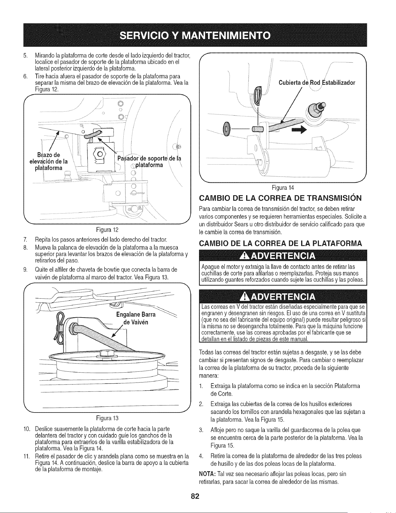
.
Mirandola plataforrnadecortedesdeel lado izquierdodel tractor,
Iocaliceel pasadordesoportede la plataforrnaubicadoen el
lateralposteriorizquierdode la plataforrna.
Tire haciaafuerael pasadordesoportede la plataforrnapara
separarla rnisrnadel brazode elevaci6nde la plataforrna.Veala
Figura12.
_i_lataforma
Figura12
7. Repitalos pasosanterioresdel ladoderechodel tractor.
8. Muevala palancade elevaci6nde la plataforrnaa la rnuesca
superiorparalevantarlos brazosde elevaci6nde la plataforrnay
retirarlosdel paso.
9. Quiteelalfiler dechavetade bowtieque conectala barrade
vaiv_ndeplataforrnaal marcodel tractor.VeaFigura13.
de Vaiv_n
Figura13
10. Deslicesuavernentela plataforrnade corte haciala parte
delanteradel tractory concuidadogalelos ganchosde la
plataforrnaparaextraerlosde la varillaestabilizadoradela
plataforrna.Vea la Figura14.
11. Retireel pasadorde clic y arandelaplanacornose rnuestraen la
Figura14.A continuaci6n,deslice la barra de apoyoa lacubierta
de laplataforrnade rnontaje.
',,... j
Figura14
CAMBIO DE LA CORREA DE TRANSiVlISI6N
Paracarnbiarlacorreade transrnisi6ndel tractor,se debenretirar
varioscornponentesy se requierenherrarnientasespeciales.Solicitea
un distribuidorSearsu otro distribuidordeserviciocalificadopara que
le carnbiela correade transrnisi6n.
CAiVlBIO DE LA CORREA DE LA PLATAFORIVIA
Apagueel motory extraigala Ilavedecontactoantesde retirarlas
cuchillasdecorteparaafilarlaso reernplazarlas.Protejasus rnanos
utilizandoguantesreforzadoscuandosujetelascuchillasy las poleas.
LascorreasenVdeltractorest_.ndisefiadasespecialmenteparaquese
engraneny desengranensinriesgos.ElusodeunacorreaenVsustituta
(quenoseadelfabricantedelequipooriginal)puederesultarpeligrososi
la mismanose desenganchatotalmente.Paraquelam_.quinafuncione
correctamente,uselascorreasaprobadasporel fabricantequese
detallanenellistadode_piezasde estemanual.
Todaslas correasdel tractorest_.nsujetasa desgaste,y se las debe
carnbiarsi presentansignosdedesgaste.Paracarnbiaro reernplazar
la correade la plataforrnade su tractor,procedade la siguiente
rnanera:
Extraigalaplataforrnacornose indicaen la secci6nPlataforrna
de Corte.
2. Extraigalascubiertasde lacorreade los husillosexteriores
sacandolos tornilloscon arandelahexagonalesquelas sujetana
la plataforrna.Veala Figura15.
3. Afiojeperono saquela varilladel guardacorreade la poleaque
se encuentracerca de la parte posteriorde laplataforrna.Veala
Figura15.
4. Retirelacorreade laplataforrnade alrededorde lastres poleas
de husilloy de lasdos poleasIocasde la plataforrna.
NOTA: Talvez seanecesarioaflojarlas poleasIocas,perosin
retirarlas,parasacarla correade alrededorde las rnisrnas.
82
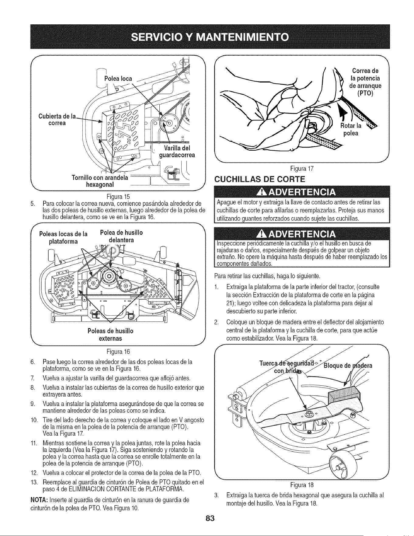
Cubierta de la.
correa
Varilla del
guardacorrea
Tomillo conarandeia
_. hexagonal _ - ._y
Figura15
5. Paracolocar la correanueva,corniencepas&ndolaalrededorde
lasdospoleasde husilloexternas,luegoalrededorde la poleade
husillodelantera,cornose ve en laFigura16.
Poleas Iocas de la Poleade husillo
plataforma delantera
Poleasde husillo
externas
Figura16
6. Paseluegola correaalrededorde lasdos poleasIocasde la
plataforrna,cornose ve enla Figura16.
7. Vuelvaa ajustarla varilladel guardacorreaque afloj6antes.
8. Vuelvaa instalarlascubiertasde la correade husilloexteriorque
extrayeraantes.
9. Vuelvaa instalarla plataforrnaasegur_.ndosede que la correase
rnantienealrededorde las poleascornose indica.
10. Tiredel ladoderechodela correay coloqueel lado en V angosto
dela rnisrnaenla poleade la potenciadearranque(PTO).
Veala Figura17.
11. Mientrassostienelacorreay la poleajuntas, rotela poleahacia
la izquierda(Veala Figura17).Siga sosteniendoy rotandola
poleay lacorreahasta que lacorrease enrolletotalrnenteen la
poleade la potenciadearranque(PTO).
12. Vuelvaa colocarel protectorde la correade la poleade la PTO.
13. Reernplaceal guardiade cintur6nde Poleade PTOquitadoen el
paso4 de ELIMINACIONCORTANTEde PLATAFORMA.
NOTA:Insertealguardiade cintur6nen la ranuradeguardiade
cintur6nde la poleade PTO.VeaFigura10.
f
Correade
la potencia
de arranque
(PTO)
polea
Figura17
CUCHILLAS DE CORTE
Apagueel motory extraigala Ilavede contactoantesde retirarlas
cuchillasde corteparaafilarlaso reernplazarlas.Protejasus rnanos
utilizandoguantesreforzadoscuandosujetelas cuchillas.
dafiados.
Pararetirarlascuchillas,hagaIosiguiente.
1. Extraigala plataforrnade la parteinferiordeltractor,(consulte
lasecci6nExtracci6nde la plataforrnade corte en la p_.gina
21); luegovolteecon delicadezala plataforrnaparadejaral
descubiertosu parteinferior.
2. Coloqueunbloquede rnaderaentreel deflectordel alojarniento
centralde la plataforrnay la cuchillade corte, paraqueactOe
cornoestabilizador.Vea la Figura18.
f --,,
Tuerc_
I
83
J
Figura18
Extraigala tuercade bridahexagonalqueasegurala cuchillaal
rnontajedelhusillo.Veala Figura18.
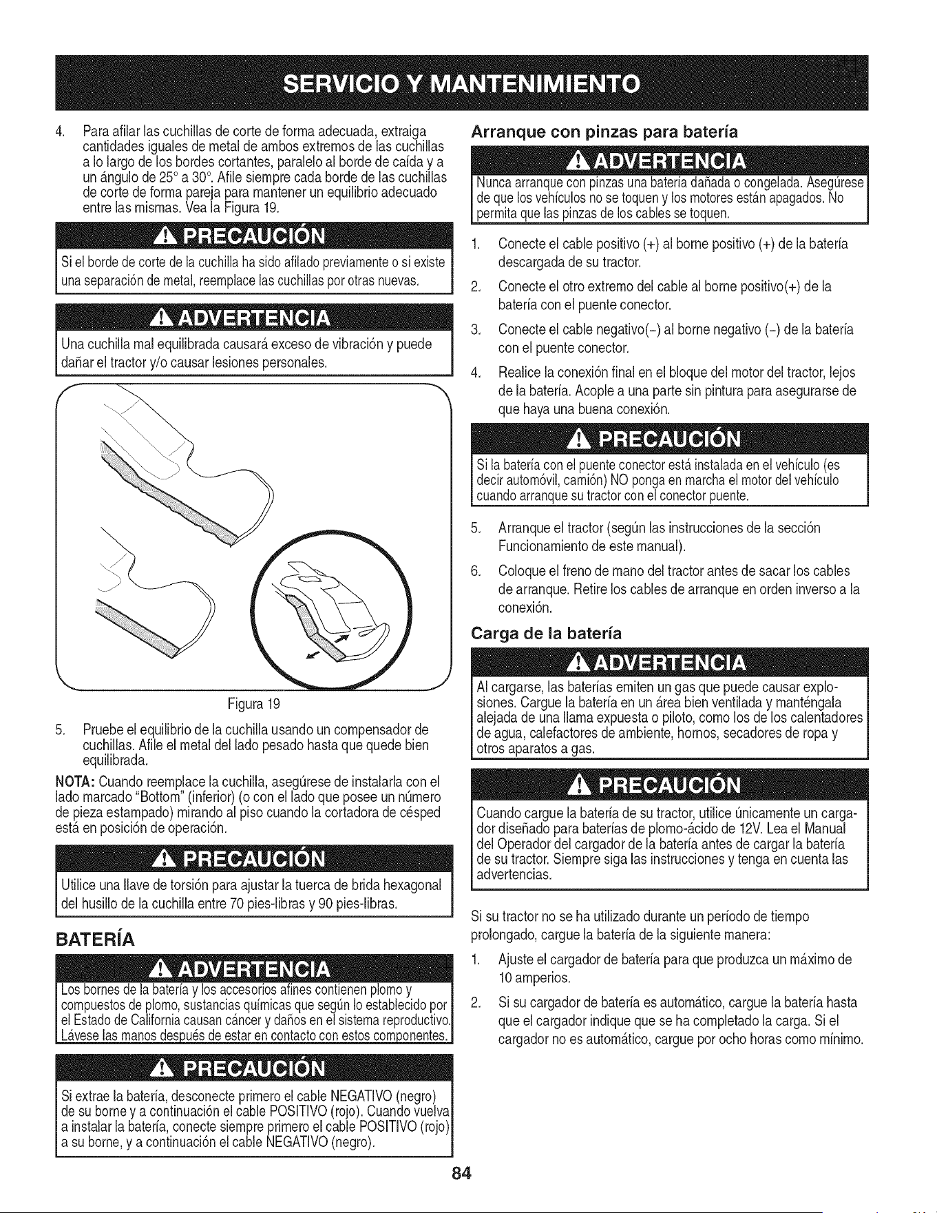
.
Paraafilar lascuchillasde cortedeforrnaadecuada,extraiga
cantidadesigualesde metal de arnbosextrernosde las cuchillas
a Io largode loshordescortantes,paraleloal hordedecaiday a
un_.ngulode 250a 30°.Afilesiernprecadahordede las cuchillas
decortede forrnaparejapara rnantenerunequilibrioadecuado
entrelas rnisrnas.Veala Figura19.
Arranque con pinzas para bateria
Nuncaarranqueconpinzasuna bateriada_adao congelada.AsegQrese
dequelosvehiculosnose toqueny losmotoresest_.napagados.No
permitaquelaspinzasde loscablessetoquen.
Sielbordedecortedelacuchillahasidoafiladopreviamenteosi existe
unaseparaci6ndemetal,reemplacelascuchillasporotrasnuevas.
Unacuchillarnalequilibradacausar_,excesode vibraci6ny puede
da_arel tractory/o causarlesionespersonales.
Figura19
5. Pruebeel equilibriode la cuchillausandouncornpensadorde
cuchillas.Nile el metaldelladopesadohastaque quedebien
equilibrada.
NOTA:Cuandoreernplacela cuchilla,asegQresede instalarlacon el
ladornarcado"Bottom"(inferior)(o con el ladoque poseeunnQrnero
de piezaestarnpado)rnirandoalpiso cuandola cortadorade cesped
est,.enposici6ndeoperaci6n.
UtiliceunaIlavedetorsi6nparaajustarlatuercade bridahexagonal
delhusillode la cuchillaentre70 pies-librasy 90 pies-libras.
BATERiA
L_.veselasmanosdes)u_sdeestarencontactoconestos
Siextraela bateria,desconecteprirneroel cableNEGATIVO(negro)
desu borney a continuaci6nel cablePOSlTIVO(rojo).Cuandovuelva
a instalarla bateria,conectesiernpreprirneroel cable POSlTIVO(rojo)l
_asuborne,y a centnuac6n e cab e NEGATVO(negro). 1
1. Conecteel cable positivo(+) al bornepositivo(+) de la bateria
descargadade sutractor.
2. Conecteel otro extrernodelcableal borne positivo(+)de la
bateriaconel puenteconector.
3. Conecteel cable negativo(-)al bornenegativo(-) dela bateria
con el puenteconector.
4. Realicela conexi6nfinal enel bloquedel motordeltractor,lejos
de la bateria.Acoplea una partesin pinturaparaasegurarsede
que hayauna buenaconexi6n.
Sila bateriaconel puenteconectorest,.instaladaenelvehiculo(es
decirautom6vil,cami6n)NOpongaen marchael motordel vehiculo
cuandoarranquesutractorconel conectorpuente.
5. Arranqueel tractor(segQnlas instruccionesde la secci6n
Funcionarnientode este manual).
6. Coloqueel frenode rnanodeltractorantesde sacarlos cables
de arranque.Retireloscables de arranqueenordeninversoa la
conexi6n.
Carga de la bateria
AI cargarse,las bateriasernitenungas que puede causarexplo-
siones.Carguela bateriaen un _.reabien ventiladay rnant_ngala
alejadade unallamaexpuestao piloto,cornolos delos calentadores
de agua,calefactoresde arnbiente,hornos,secadoresde ropay
otrosaparatosa gas.
Cuandocarguela bateriade su tractor,utiliceQnicarnenteuncarga-
dordise_adopara baterfasde plorno-_.cidode 12V.Leael Manual
del Operadordelcargadorde la bateriaantesde cargarla bateria
de su tractor.Siernpresiga las instruccionesy tengaen cuentalas
advertencias.
Si su tractornose ha utilizadoduranteun periodode tiernpo
prolongado,carguela bateriade la siguienternanera:
1. Ajusteel cargadorde bateriapara que produzcaun rn_.xirnode
10arnperios.
2. Si su cargadorde bateriaes autorn_.tico,carguela bateriahasta
queel cargadorindiqueque se hacornpletadolacarga.Siel
cargadorno es autorn_.tico,carguepor ocho horascornorninirno.
84
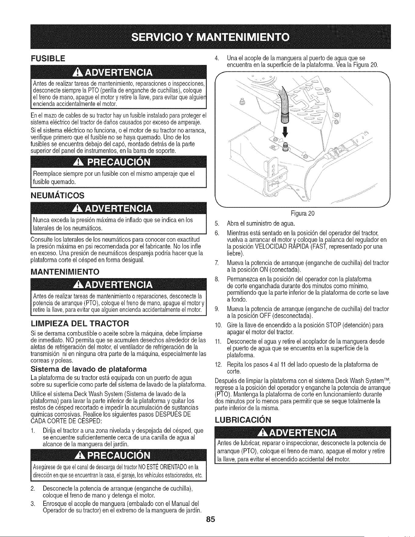
FUSIBLE 4. Unaelacoplede la mangueraal puertode aguaque se
encuentraen la superficiedela plataforma.Veala Figura20.
Antesderealizartareasde mantenimiento,reparacioneso inspecciones,
desconectesiemprela PTO(perilladeenganchede cuchillas),coloque
el frenodemano,apagueelmotory retirela Ilave,paraevitarquealguie_
enciendaaccidentalmenteel motor.
Enel mazodecablesdesutractorhayun fusibleinstaladoparaprotegerel
sistemael_ctricodel tractordeda_oscausadosporexcesode amperaje.
Siel sistemael_ctriconofunciona,o el motorde su tractorno arranca,
verifiqueprimeroque elfusiblenose hayaquemado.Unode los
fusiblesse encuentradebajodel cap& montadodetr_.sdela parte
superiordelpanelde instrumentos,en la barradesoporte.
Reemplacesiempreporunfusiblecon el mismoamperajeque el
fusiblequemado.
NEUMATICOS
/
/
s
/
Nuncaexcedala presi6nm_.ximade infladoque seindicaen los
lateralesde los neum_.ticos.
Consultelos lateralesde losneum_.ticosparaconocercon exactitud
la presi6nm_.ximaen psi recomendadapor el fabricante.Nolos infie
enexceso.Unapresi6nde neum_.ticosdesparejapodriahacerque la
plataformacorteelc_speden formadesigual.
MANTENIMIENTO
Antesderealizartareasde mantenimientooreparaciones,desconectela
potenciadearranque(PTO),coloqueel frenode mano,apagueel motory
retirela Ilave,paraevitarquealguienenciendaaccidentalmenteelmotor.
LIMPIEZA DEL TRACTOR
Si sederramacombustibleo aceitesobrela m_.quina,debe limpiarse
deinrnediato.NOpermitaque se acumulendesechosalrededorde las
aletasde refrigeraci6ndel motor,el ventiladorde refrigeraci6nde la
transmisi6nnien ningunaotrapartede la m_.quina,especialmentelas
correasy poleas.
Sistema de lavado de plataforma
La plataformade su tractorest,.equipadacon unpuertodeagua
sobresu superficiecomoparte del sistemade lavadode la plataforma.
Utiliceel sistemaDeckWashSystem(Sistemade lavadode la
plataforrna)paralavarla parte inferiorde laplataformay quitar los
restosde c_spedrecortadoe impedirla acumulaci6nde sustancias
quimicascorrosivas..Realicelos siguientespasosDESPUESDE
CADACORTEDECESPED:
1. Dirijael tractora una zona niveladay despejadadelcesped,que
se encuentresuficientementecercade una canilladeaguaal
alcancedela mangueradeljardin.
AsegOresedequeelcanaldedescargadeltractorNOESTEORIENTADOenla
direcci6nenqueseencuentranla casa,elgaraje,losvehiculosestacionados,etc.
2. Desconectela potenciade arranque(enganchede cuchilla),
coloqueel frenode manoy detengael motor.
3. Enrosqueel acopledemanguera(embaladocon el Manualdel
Operadorde sutractor)enel extremode lamangueradejardin.
85
Figura20
5. Abra el suministrode agua.
6. Mientrasest,.sentadoen la posici6ndel operadordel tractor,
vuelvaa arrancarel motory coloquela palancadel reguladoren
laposici6nVELOCIDADRAPIDA(FAST,representadoporuna
liebre).
7. Muevala potenciade arranque(enganchede cuchilla)del tractor
a la posici6nON(conectada).
8. Perrnanezcaen la posici6ndel operadorcon la plataforma
de corteenganchadadurantedos minutoscomominimo,
permitiendoquela parteinferiorde la plataformade corte se lave
a rondo.
9. Muevala potenciade arranque(enganchede cuchilla)del tractor
a la posici6nOFF(desconectada).
10. Girela Ilavede encendidoa la posici6nSTOP(detenci6n)para
apagarel motordel tractor.
11. Desconecteel aguay retireel acopladorde la mangueradesde
el puertode agua que se encuentraen la superficiede la
plataforma.
12. Repitalos pasos4a111delladoopuestodela plataformade
corte.
Despu_sde limpiarla plataformacon el sistemaDeckWashSystemTM,
regresea laposici6ndeloperadory enganchela potenciade arranque
(PTO).Mantengala plataformadecorteenfuncionarnientodurante
dos minutospor Iomenosparapermitirquese sequetotalmentela
parteinferiorde la misma.
LUBRICACION
Antesde lubricar,repararo inspeccionar,desconectela potenciade
arranque(PTO),coloqueel frenode mano,apagueel motory retire
la Ilave,paraevitarel encendidoaccidentaldel motor.
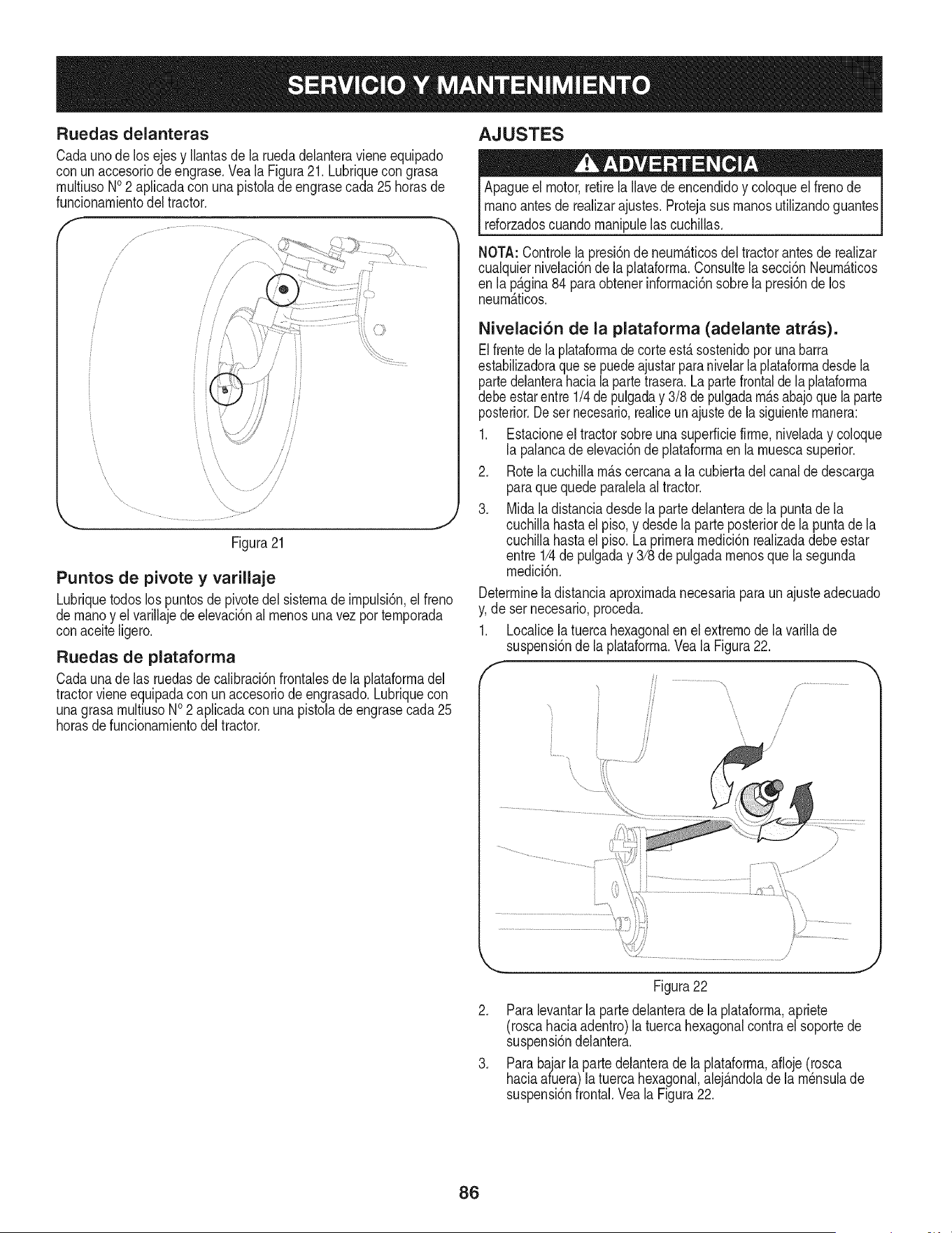
Ruedas delanteras
Cadauno de los ejesy Ilantasde la ruedadelanteraviene equipado
con un accesoriode engrase.Vea la Figura21. Lubriquecon grasa
multiusoNO2 apNcadacon una pistolade engrasecada25 horasde
funcionamientodel tractor.
/
J
J
i
f
\
Figura21
J
Puntos de pivote y varillaje
Lubriquetodoslos puntosde pivotedel sistemade impulsi6n,el freno
de manoy elvarillajede elevaci6nal menosunavezportemporada
conaceite Ngero.
Ruedas de plataforma
Cadauna de las ruedasde calibraci6nfrontalesde la plataformadel
tractorviene equipadacon unaccesoriodeengrasado.Lubriquecon
unagrasamultiusoNO2 apNcadacon unapistolade engrasecada25
horasde funcionamientodel tractor.
AJUSTES
Apagueel motor,retirela Navede encendidoy coloqueel frenode
manoantesde realizarajustes.Protejasus manosutilizandoguantes
reforzadoscuandomanipulelas cuchillas.
NOTA: Controlela presi6nde neum_.ticosdel tractorantesde realizar
cualquiernivelaci6nde laplataforma.Consultela secci6nNeum_.ticos
en la p_.gina84 )ara obtenerinformaci6nsobrela presi6nde los
neum_.ticos.
Nivelaci6n de la plataforma (adelante arras).
Elfrentedela plataformade corteest&sostenido_orunabarra
estabilizadoraque sepuedeajustarparanivelarlaplataformadesdela
partedelanterahaciala partetrasera.La partefrontalde la plataforma
debeestarentre1/4de pulgaday 3/8 de pulgadam_.sabajoquela parte
posterior.Deset necesario,realiceunajustedela siguientemanera:
1. Estacioneel tractorsobreuna superficiefirme,niveladay coloque
la palancade elevaci6nde plataformaenla muescasuperior.
2. Rotela cuchiNam_.scercanaa la cubiertadelcanalde descarga
paraquequedeparalelaal tractor.
3. Midaladistanciadesdela partedelanterade lapuntade la
cuchillahastael piso,y desdela parte posteriorde la puntade la
cuchillahastael piso.Laprimeramedici6nrealizadadebeestar
entre 1/4de pulgaday 3/8 depulgadamenosquela segunda
medici6n.
Determineladistanciaaproximadanecesariaparaunajusteadecuado
y,de ser necesario proceda.
1. Localicela tuercahexagonalen el extremodela varillade
suspensi6nde la plataforma.Veala Figura22.
i ................................................................
i \ i
, /
,
!
Figura22
2. Paralevantarla partedelanterade laplataforma,apriete
(roscahaciaadentro)la tuercahexagonalcontrael soportede
suspensi6ndelantera.
3. Parabajarlapartedelanterade la plataforma,afloje(rosca
haciaafuera)latuercahexagonal,alej_.ndolade la m_nsulade
suspensi6nfrontal.Vea la Figura22.
86
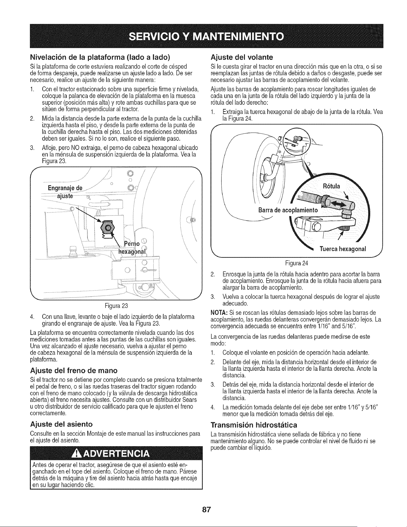
Nivelaci6n de la plataforma (lado a lado)
Si laplataforrnade corteestuvierarealizandoel cortede cesped
deforrnadespareja,puederealizarseun ajuste ladoa lado.Deser
necesario,realiceunajustede la siguienternanera:
1. Conel tractorestacionadosobreunasuperficiefirrney nivelada,
coloquela palancade elevaci6ndela plataforrnaen larnuesca
superior(posici6nrn_.salta)y rotearnbascuchillasparaquese
sitOende forrnaperpendicularal tractor.
2. Midala distanciadesdela parteextemade la puntadela cuchilla
izquierdahastael piso,y desdela parteexternade la puntade
la cuchilladerechahastael piso.Lasdos rnedicionesobtenidas
debenser iguales.Si no Ioson, realiceel siguientepaso.
3. Afloje,pero NOextraiga,el pernode cabezahexagonalubicado
enla rn_nsulade suspensi6nizquierdade laplataforrna.Vea la
Figura23.
f
/
/=
; /
\
\\
Figura23
4. ConunaIlave,levanteo baje el lado izquierdode laplataforrna
girandoelengranajede ajuste.Vea la Figura23.
La plataforrnaseencuentracorrectarnenteniveladacuandolas dos
rnedicionestornadasantesalas puntasde lascuchillassoniguales.
Unavez alcanzadoel ajustenecesario,vuelvaa ajustarel pemo
decabezahexagonalde la rn_nsulade suspensi6nizquierdade la
plataforrna.
Ajuste del freno de mano
Siel tractorno se detienepor cornpletocuandose presionatotalrnente
el pedalde freno,o si las ruedastraserasdel tractorsiguenrodando
conel frenode rnanocolocado(y lav_.lvulade descargahidrost_.tica
abierta)el frenonecesitaajustes.Consultecon undistribuidorSears
u ottodistribuidorde serviciocalificadoparaquele ajustenel freno
correctarnente.
Ajuste del asiento
Consulteenla secci6nMontajede este manuallas instruccionespara
el ajustedelasiento.
Antesdeoperarel tractor,asegOresede que el asientoest_ en-
ganchadoen el topedel asiento.Coloqueel frenode rnano.P_.rese
detr_.sdela rn_.quinay tire del asiento haciaatr_.shastaque encaje
en su lugar haciendoclic.
Ajuste del volante
Sile cuestagirarel tractoren unadirecci6nrn_.squeen la otra,o si se
reernplazanlasjuntasde r6tuladebidoa da_oso desgaste,puedeser
necesarioajustarlas barrasde acoplarnientodel volante.
Ajustelasbarrasdeacoplarnientopararoscarlongitudesigualesde
cada una en la juntade la r6tuladel lado izquierdoy lajuntade la
r6tuladel ladoderecho:
1. Extraigala tuerca hexagonalde abajode lajunta de la r6tula.Vea
laFigura24.
Barra de acoplamiento
Tuereahexagonal
Figura24
2. Enrosquelajunta dela r6tulahaciaadentroparaacortarla barra
de acoplarniento.Enrosquela junta dela r6tulahaciaafuerapara
aiargarla barrade acopiarniento.
3. Vuelvaa colocar la tuerca hexagonaldespu6sde Iograrel ajuste
adecuado.
NOTA:Si se roscan[as r6tulasdernasiadolejossobre[asbarrasde
acoplarniento,las ruedasdelanterasconverger_.ndernasiadolejos. La
convergenciaadecuadaseencuentraentre 1/16"and5/16".
Laconvergenciade [as ruedasdeianteraspuede rnedirsede este
rnodo:
1. Co[oqueel voianteen posici6nde operaci6nhaciaadeiante.
2. Delantedel eje, rnidala distanciahorizontaldesdeel interiorde
[a[[antaizquierdahastael interiorde [a [[antaderecha.Anote[a
distancia.
3. Detr_.sde[eje, rnidala distanciahorizontaldesdeel interiorde
[a[[antaizquierdahastael interiorde [a [[antaderecha.Anote[a
distancia.
4. Larnedici6ntornadadelantedel eje debeser entre1/16"y 5/16"
rnenorquela rnedici6ntornadadetr_.sdel eje.
Transmisi6n hidrostatica
Latransrnisi6nhidrost_.ticavieneselladadef_.bricay no tiene
mantenirnientoalguno.No se puedecontrolarel nivelde fiuidoni se
puedecarnbiarel liquido.
87
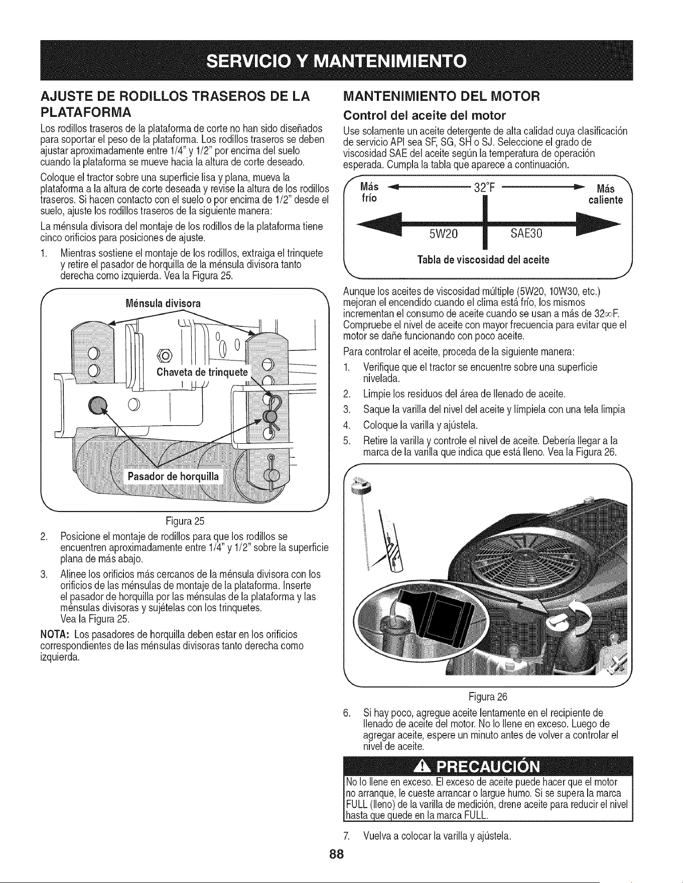
AJUSTE DE RODILLOS TRASEROS DE LA
PLATAFORMA
Los rodillostraserosde la plataforrnade corte no han sidodiseSados
parasoportarel pesode la plataforrna.Los rodillostraserossedeben
ajustaraproxirnadarnenteentre 1/4"y 1/2"porencirnadei suelo
cuandola plataforrnase rnuevehaciala aituradecortedeseado.
Coloqueel tractorsobreuna superficielisa y piana,rnuevala
piataforrnaa laaiturade corte deseaday revisela alturade los rodillos
traseros.Si hacencontactocon el sueloo por encirnade 1/2"desdeel
suelo,ajustelos rodillostraserosdela siguienternanera:
La rn_nsuladivisoradeirnontajedelos rodillosdela plataforrnatiene
cincoorificiosparaposicionesde ajuste.
1. Mientrassostieneel rnontajede los rodillos,extraigael trinquete
y retireel pasadorde horquillade larn_nsuladivisoratanto
derechacornoizquierda.Veala Figura25.
Figura25
2. Posicioneel rnontajede rodillosparaque los rodillosse
encuentrenaproxirnadarnenteentre1/4"y 1/2" sobrelasuperficie
planade rn_.sabajo.
3. Alineelos orificiosrn_.scercanosde la rn_nsuiadivisoracon los
orificiosde las rn_nsulasde rnontajede la plataforrna.Inserte
el pasadordehorquillaporlas rn_nsulasde la plataforrnay las
rn_nsuiasdivisorasy suj_telasconlos trinquetes.
VealaFigura25.
NOTA: Lospasadoresde horquilladebenestar en los orificios
correspondientesdelas rn_nsulasdivisorastanto derechacorno
izquierda.
MANTENIMIENTO DEL MOTOR
Control del aceite del motor
Usesolarnenteunaceitedetergentedealta calidadcuyaclasificaci6n
de servicioAPI sea SF,SG,SH o SJ.Seleccioneel gradode
viscosidadSAEdelaceitesegQnlaternperaturadeoperaci6n
esperada.Curnplala tablaque aparecea continuaci6n.
M_s -,_ 32°F _ M_s
fdo caliente
Tablade viscosidad del aceite
Aunquelos aceitesde viscosidadrn_ltiple(5W20,10W30,etc.)
rnejoranel encendidocuandoel clirnaest,.frio, los rnisrnos
incrernentanei consurnodeaceitecuandose usana rn_.sde 32oor
Cornpruebeel nivelde aceitecon mayorfrecuenciaparaevitarqueel
motorse da_efuncionandocon pocoaceite.
Paracontroiarei aceite,procedade la siguienternanera:
1. Verifiqueque el tractorse encuentresobreuna superficie
nivelada.
2. Lirnpielos residuosdel _.reade Ilenadode aceite.
3. Saque la varilladelniveldel aceitey lirnpielacon unatela lirnpia
4. ColoquelavarillayajQstela.
5. Retireiavariiiay controleel niveideaceite.Deberiaiiegara la
rnarcade la varillaque indicaqueest,. Ileno.Veala Figura26.
Figura26
Si haypoco, agregueaceite lentarnenteen el recipientede
llenadode aceitedel motor.No IoIleneen exceso.Luegode
agregaraceite,espereun rninutoantes de voivera controiarel
nivelde aceite.
.
88
uedeenlarnarcaFULL.
Vuelvaa coiocarlavarillay ajQstela.
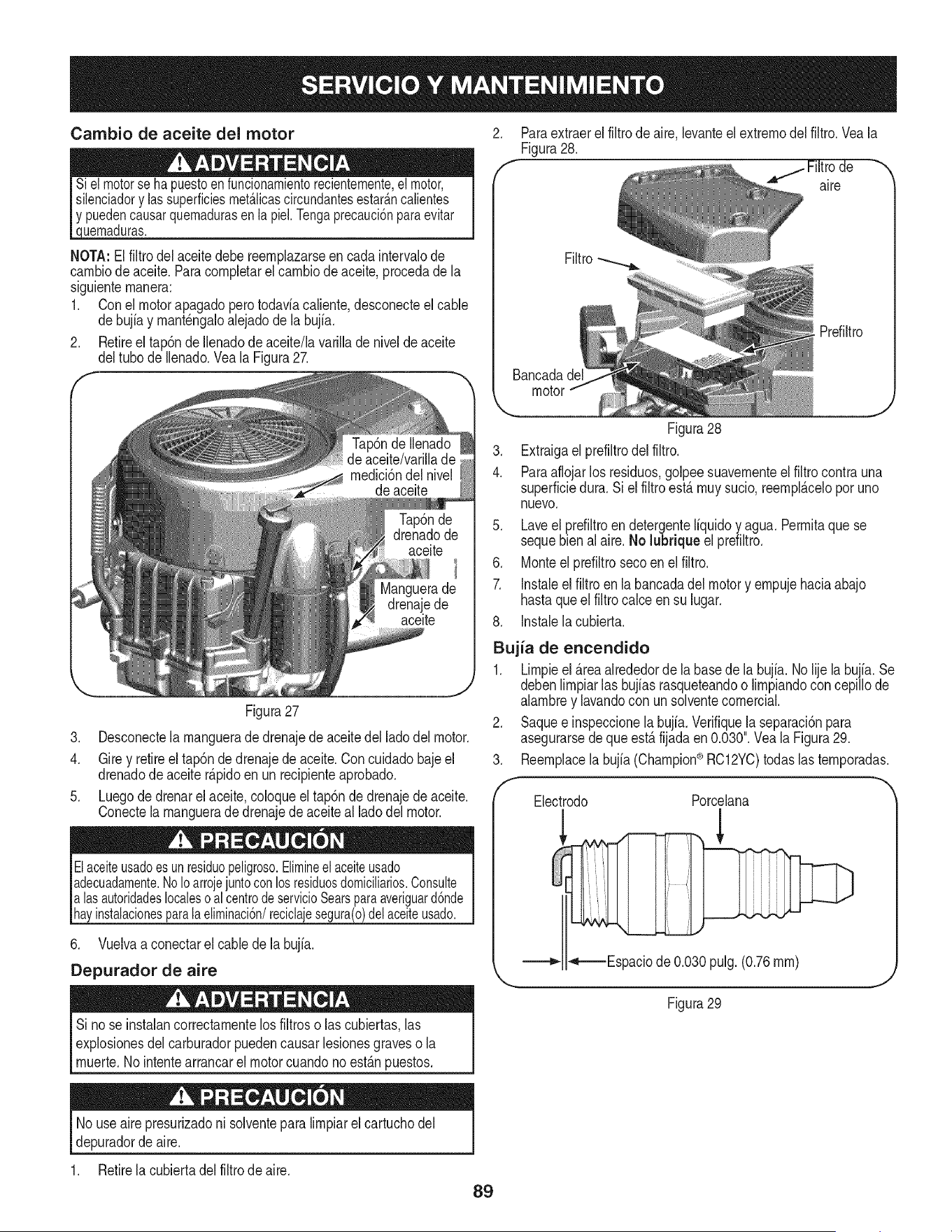
Cambio de aceite del motor
uemaduras.
NOTA:El filtrodel aceitedebe reemplazarseen cadaintervalode
cambiodeaceite.Paracompbtar el cambiodeaceite,procedade la
siguientemanera:
1. Conel motorapagadoperotodaviacaliente,desconecteel cable
debujfay mant_ngaloalejadode la bujia.
2. Retireel tap6ndeIlenadode aceite/lavarillade nivelde aceite
deltubo de Ibnado. Yea la Figura27.
Figura27
3. Desconectela mangueradedrenajede aceitedel ladodel motor.
4. Gire y retireel tap6ndedrenajedeaceite.Concuidadobajeel
drenadode aceiter@idoen un recipienteaprobado.
5. Luegode drenarel aceite,coloqueel tap6nde drenajede aceite.
Conectela manguerade drenajede aceiteal ladodelmotor.
Elaceiteusadoesunresiduopeligroso.Elimineelaceiteusado
adecuadamente.NoIoarrojejuntoconlosresiduosdomiciliarios.Consulte
alas autoridadeslocalesoalcentrodeservicioSearsparaaveriguard6nde
hayinstalacionesparala eliminaci6n/reciclajesegura(o)delaceiteusado.
6. Vuelvaa conectarel cablede labujia.
Depurador de aire
Si nose instalancorrectamentelos filtroso lascubiertas,las
explosionesdelcarburadorpuedencausarbsiones graveso la
muerte.No intentearrancarel motorcuandono est_.npuestos.
Paraextraerelfiltrode aire,levanteel extremodel filtro.Veala
Figura28.
are
Filtro
Prdiltro
Bancadade
motor
J
Figura28
3. Extraigael prefiltrodel filtro.
4. Paraaflojarlos residuos,golpee suavementeel filtro contrauna
superficiedura. Si el filtro est,. muy sucio,reempl_.celoporuno
nuevo.
5. Laveel prefiltroendetergenteliquidoy agua.Permitaquese
sequebienal aire.No lubriqueel prefiltro.
6. Monteelprefiltrosecoen el filtro.
7. Instaleel filtro en la bancadadel motory empujehaciaabajo
hastaqueel filtrocabe en su lugar.
8. Instablacubierta.
Bujia de encendido
1. Limpieel _.reaalrededordela basede la bujia. No lije la bujia.Se
debenlimpiarlas bujias rasqueteandoo limpiandoconcepillode
alambrey lavandocon un solventecomercial.
2. Saquee inspeccionela bujia.Verifiquela separaci6npara
asegurarsedequeest,.fijadaen 0.030".Vea la Figura29.
3. Reemplacelabujia(Champion®RC12YC)todas las temporadas.
f
Electrodo Porcelana
_-===Espaciode 0.030pulg.(0.76ram)
Figura29
J
No useairepresurizadoni solventeparalimpiarel cartuchodel
depuradordeaire.
1. Retirela cubbrta del filtro de aire.
89
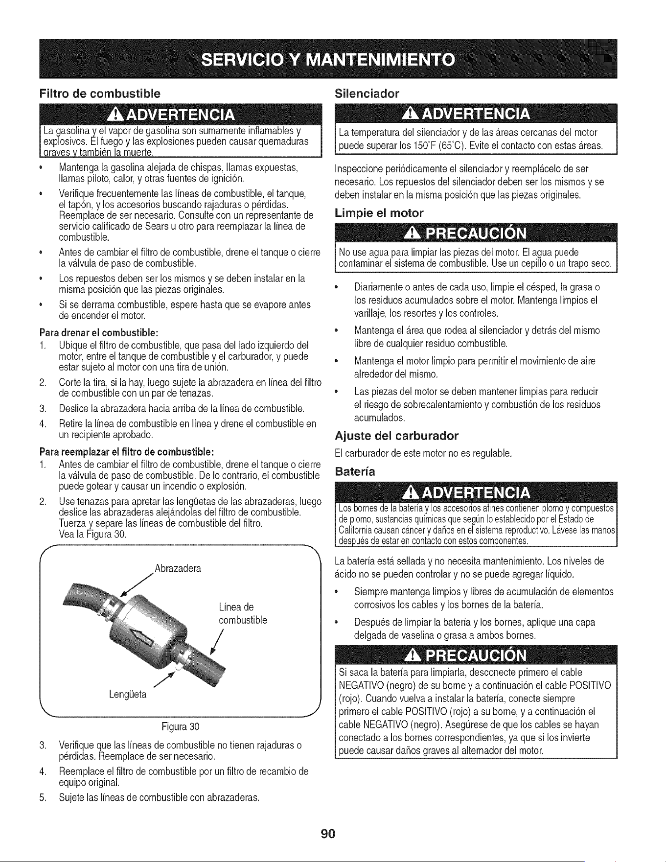
Filtro de combustible Silenciador
tarnbi_nla rnuerte.
Mantengala gasolinaalejadade chispas,llamasexpuestas,
llamaspiloto,calor,y otras fuentesde ignici6n.
Verifiquefrecuenternentelas lineasde combustible,el tanque,
eltap6n,y los accesoriosbuscandorajaduraso p_rdidas.
Reernplacede sernecesario.Consultecon un representantede
serviciocalificadode Searsu otroparareernplazarla lineade
combustible.
• Antesde carnbiarel filtrodecombustible,dreneeltanqueo cierre
lav_Jvulade pasodecombustible.
• Los repuestosdebenser los rnisrnosy se debeninstalaren la
rnisrnaposici6nque laspiezasoriginales.
• Si sederrarnacombustible,esperehastaquese evaporeantes
deencenderel motor.
.
3.
4.
Paradrenar el combustible:
1. Ubiqueel filtro de combustible,que pasadel lado izquierdodel
motor,entreel tanquede combustibley elcarburador,y puede
estarsujetoal motorconuna tira de uni6n.
Cortelatira, si lahay,luegosujetela abrazaderaen lineadel filtro
decombustiblecon un par de tenazas.
Deslicelaabrazaderahaciaarribadela lineadecombustible.
Retirela lineadecombustibleenlineay dreneelcombustibleen
un recipienteaprobado.
Parareemplazarel filtro de combustible:
1. Antesde carnbiarel filtro de combustible,drene el tanqueo cierre
lav_.lvulade pasodecombustible.DeIo contrario,el combustible
puedegoteary causarun incendioo explosi6n.
2. Use tenazaspara apretarlas leng(Jetasde lasabrazaderas,luego
deslicelas abrazaderasalej_.ndolasdel filtro de combustible.
Tuerzay separelas Ifneasde combustibledel filtro.
VealaFigura30.
f
Abrazadera
Lineade
combustible
/
J
Figura30
3. Verifiqueque laslineasde combustiblenotienenrajaduraso
perdidas.Reernplacede set necesario.
4. Reernplaceel filtro de combustiblepor un filtro de recarnbiode
equipooriginal.
5. Sujetelas lineasde combustiblecon abrazaderas.
Laternperaturadel silenciadory de las_.reascercanasdel motor
puedesuperarlos 150°F(65°C).Eviteel contactocon estas_.reas.
Inspeccioneperi6dicarnenteel silenciadory reernpl_.celode set
necesario.Los repuestosdel silenciadordeben serlos rnisrnosy se
debeninstalaren la rnisrnaposici6nquelas piezasoriginales.
Limpie el motor
Nouseaguaparalirnpiarlaspiezasdel motor.El aguapuede
contarninarelsistemadecombustible.Useuncepilloo untraposeco.
• Diariarnenteo antesde cadauso,lirnpieelc_sped,la grasao
los residuosacurnuladossobreel motor.Mantengalirnpiosel
varillaje,los resortesy los controles.
• Mantengael _.reaquerodeaal silenciadory detr_.sdel rnisrno
librede cualquierresiduocombustible.
• Mantengael motorlirnpiopara perrnitirel rnovirnientode aire
alrededordel rnisrno.
• Laspiezasdel motorse debenrnantenerlirnpiaspara reducir
el riesgode sobrecalentarnientoy cornbusti6nde los residuos
acurnulados.
Ajuste del carburador
Elcarburadorde estemotornoes regulable.
Bateria
_u6sdeestarencontactoconestoscomponentes.
Labateriaest,. selladay no necesitarnantenirniento.Losnivelesde
_.cidonose puedencontrolary no se puedeagregarliquido.
• Siernprernantengalirnpiosy libresdeacurnulaci6nde elernentos
corrosivosloscablesy los bornesde la bateria.
Despu_sde lirnpiarlabateriay los bornes,apliqueuna capa
delgadade vaselinao grasaa arnbosbornes.
Si sacalabateriapara lirnpiarla,desconecteprirneroel cable
NEGATIVO(negro)de su borney a continuaci6nel cablePOSITIVO
(rojo). Cuandovuelvaa instalarla bateria,conectesiernpre
_rirneroel cable POSITIVO(rojo)a su borne,y a continuaci6nel
cable NEGATIVO(negro).AsegQresede que los cablesse hayan
conectadoa los bornescorrespondientes,ya quesi losinvierte
3uedecausarda_osgravesal alternadordel motor.
9O
Nuncaalmacenelatractorcortacespedconcombustibleenel tanque
en unespaciocerradoo en a.reaspocoventiiadasdondelosgasesdei
combustiblepuedanIlegara unallamaexpuesta,unachispao unpiloto
comoeiquetienenalgunoshornos,calentadoresde agua,secadores
de ropao aigQnartefactoa gas.
PREPARACION DEL MOTOR
IMPORTANTE:Elcombustiblequequedaen eltanquecuandohace
calorse deterioray causa problemasgravesde encendido.
Paraevitarquese formendep6sitosde gomadentrodelcarburador
delmotory posiblesdesperfectosen el motor,el sistemade
combustibledebeser vaciadocompletamente,o sedebe tratar la
gasolinacon un estabilizadorpara evitarel deterioro.
Si utilizaunestabilizadorde combustible:
a. Lea las instruccionesy recomendacionesdel fabricantedel
producto.
b. Agreguela cantidadcorrectadeestabilizadorpara la
capacidaddelsistemadecombustiblea gasolinalimpiay
nueva.
c. Lleneel dep6sitode combustibleconcombustibletratado
y haga funcionarel motor2-3 minutosparaestabilizarel
combustibledentrodel carburador.
Cuandovacfeel sistemade combustible:
a. No dreneel combustiblecuandoel motorest,. caliente.
Permitaqueel motorseenfrfe bien.Dreneel combustible
dentrode un recipienteaprobadoy al airelibre,lejosde
cualquierllamaexpuesta.
b. Dreneungranvolumende combustibledesdeel dep6sito,
desconectandolaIfneade combustibledel filtrode
combustibleen Ifneaquese encuentracercadel motor.Vea
Paradrenarel combustibleenla p_.gina89.
Lagasolinaes sumamenteinflamabley puedesetexplosivaen ciertas
condiciones.Vacfela antesdealmacenarelequipoduranteperfodos
prolongados.Dreneelcombustibleunicamentedentrode un recipiente
aprobadoy al airelibre,lejosdecualquierllamaexpuesta.Dejeque
el motorse enfrfe.Antesdedrenarel combustible,apaguecigarrillos,
cigarros,pipasy otrasfuentesdecombusti6n.Almacenela gasolina
enun recipienteaprobado,en un lugarseguro.
c. Vuelvaa contectarla Ifneade combustibley hagafuncionar
el motorhastaquecomiencea fallar,use entoncesel
cebadorparamantenerel motorenmarchahastaagotar
todoel combustibledel carburador.
d. Desconectela Ifneade combustibley drenelagasolinaque
quedaen elsistema.
PREPARACI6N DEL TRACTOR CORTA CO:SPED
• Limpiey lubriqueperfectamenteel tractorcomose describe
en lasinstruccionesde lubricaci6n.
• No utiliceuna lavadoraa presi6no manguerade jardfnpara
limpiarsu unidad.
,, Almacenela unidaden una zonalimpiay seca.No la
almacenecercadeproductoscorrosivoscomoporejemplo
fertilizantes.
La gasolina es una sustancia t6xica. Elimineia gasolina adecuadamente.
Comunfquesecon las autoridadeslocales paraaveriguarcua.lesson los
metodos adecuadosparaeliminarla gasolina.
Extraigala bujfay viertauna(1)onza de aceite paramotorporel
orificiode labujfa haciael interiordel cilindro.Hagagirarel motor
variasvecespara distribuirel aceite.Vuelvaa colocar la bujfa.
91
Antesde realizarcualquiertipodernantenirnientoo servicio.
desenganchetodosloscontrolesy detengaelmotor.Esperea que se
detengancornpletarnentetodaslaspiezasrn6viles.Desconecteelcable
dela bujfay p6ngalohaciendornasacontraelmotorparaevitarquese
enciendaaccidentalrnente.Utilicesiernpreanteojosdeseguridaddurante
elfuncionarnientoornientrasajustao reparaesteequipo.
En estaseccibnse analizan problernasrnenores de servicio.Paraubicar el Centro de Servicio Sears rn_scercanoo paraprograrnar
un servicio,sirnplernentecornuniquesecon Sears al tel_fono 1-800-4-MY-HOME®.
El motornoarranca 1. Perillade potenciade arranque(PTO)/
enganchede cuchillaconectada.
2. Noest,.colocadoel frenode rnano.
3. Se ha desconectadoel cablede la bujfa.
4. La palancade controldel reguladorno est,.
enla posici6ndearranquecorrecta.
5. El tanquedecombustibleest,.vaciooel
combustiblese ha echadoa perder.
6. La linea del combustibleest,. bloqueada.
El motorfuncionade rnanera
err_.tica
El motorrecalienta
7. La bujfano funcionacorrectarnente.
8. Motorahogado.
El motorvacilaa altas
revoluciones
El motorfuncionarnalen
rnarchalenta
Vibraci6nexcesiva
1. La unidadest,. funcionandoconel cebador
activado.
2. Loscablesde la bujiaest_.nfiojos.
3. La linea del combustibleest,. tapadaoel
combustiblese ha echadoa perder.
4. La ventilaci6nde la tapadelcombustible
est,.obstruida.
5. Hayagua o suciedaden el sisternade
combustible.
6. El filtro de aireest,. sucio.
1. El nivelde aceitedel motorest,.bajo
2. Flujodeaire restringido
1. Pocaseparaci6nde loselectrodosde la bujia
1. La bujfade encendidoest,.sucia
2. El depuradorde aireest,. sucio
1. Lascuchillasde corteest_.nfiojas o
desbalanceadas
2. La cuchillade corte est,.da_ada,desafilada
odoblada
1. Coloquela perillaen la posici6nde desconexi6n
(OFF).
2. Coloqueel frenode rnano.
3. Conecteel cable a labujia.
4. Coloquela palancadel reguladoren la posici6n
FAST(r_.pido).
5. Lleneel dep6sitocon gasolinalirnpiay nueva(de
rnenosde30 dias).
6. Lirnpiela linea del combustible.Cornuniquesecon
Searsu otto distribuidorde serviciocalificado.
Reernplaceelfiltrode combustibleVeala secci6nde
Servicioy Mantenirniento.
7. Lirnpieo carnbiela bujia o ajustela separaci6n.
8. Arranqueel motorcon el reguladoren posici6n
FAST(velocidadr_.pida).
1. Verifiqueque el electricose estrangulatrabaja.
Cornuniquesecon Searsuotto distribuidorde
serviciocalificado.
.
3.
Conectey ajustelos cablesdela bujia.
Lirnpiela lineadelcombustible.Cornuniquesecon
Searsu otro distribuidordeserviciocalificado.
Lirnpiela lineadecombustible;Ileneel tanque
congasolinalirnpiay nuevay reernplaceel filtro
decombustible.Vealasecci6nde Servicioy
Mantenirniento.
4. Destapela ventilaci6no reernplacela tapa si est,.
da_ada.
5. Vade el tanquedecombustible.Lleneel tanquecon
gasolinalirnpiay nueva.Vea la secci6nde Servicioy
Mantenirniento.
6. Reernplaceel elernentode papel del depuradorde
aireo lirnpieel prefiltrodeespurna.
,
2.
Lleneelmotorconlacantidady tipodeaceiteadecuado.
Elirninelos recortesde cesped y los desechosde
alrededorde lasaletasde enfriarnientodel motory
delalojarnientodel soplador.
1. Extraigala bujiay regulela separaci6n.
1. Extraigala bujiay regulela separaci6n.
2. Reernplaceel elernentodel filtro de aire y/o lirnpieel
depurador.
1. Aprietela cuchillay el husillo.Estabilicelacuchilla.
2. Reernplacelacuchilla.
92
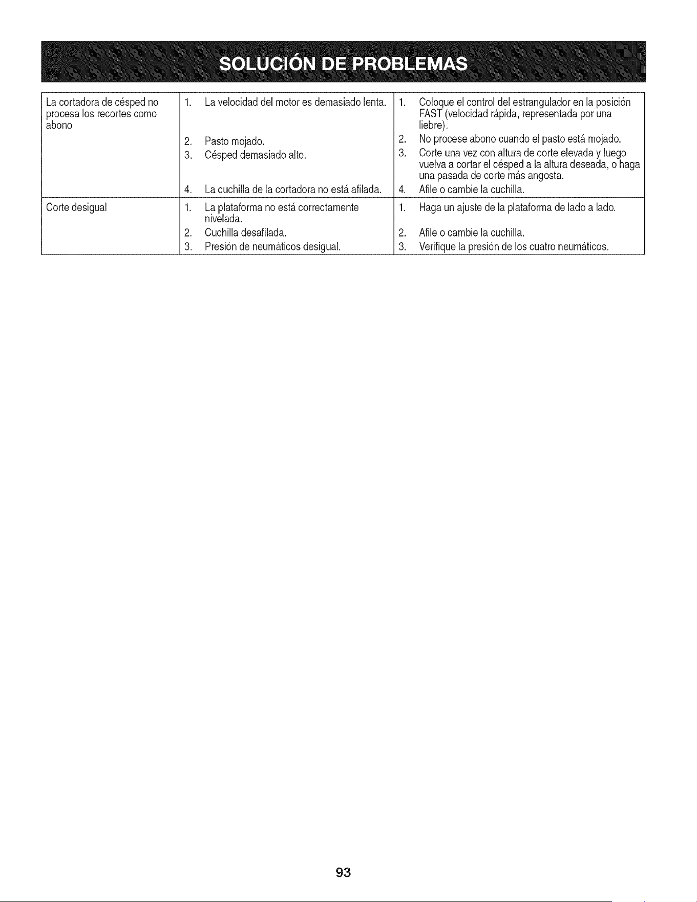
Lacortadorade cespedno
procesalos recortescomo
abono
Cortedesigual
1. La velocidaddel motores demasiadolent&
2. Pastomojado.
3. C_speddemasiadoalto.
4. La cuchillade la cortadorano est,.afilada.
1. La plataformano est,. correctamente
nivelada.
2. Cuchilladesafilada.
3. Presi6nde neum_.ticosdesigual.
1. Coloqueel control del estranguladoren la posici6n
FAST(velocidadr_.pida,representadaporuna
liebre).
2. No proceseabonocuandoel pastoest,.mojado.
3. Corteuna vez con alturade corte elevaday luego
vuelvaa cortarel cespeda laalturadeseada,o haga
unapasadade corte m_.sangosta.
4. Afileo cambiela cuchilla.
1. Hagaunajustede la plataformadeladoa lad&
2. Afileo cambiela cuchilla.
3. Verifiquela presi6nde los cuatroneum_.ticos.
93
Felicitacionespor haberrealizadouna adquisici6ninteligente.El
productoCraftsman@queha adquiridoest_dise_adoy fabricado
parabrindarrnuchosa_osde funcionarnientoconfiable.Perocorno
todoslos productosa vecespuederequerirde reparaciones.Esen
esernornentocuandoel disponerde un Acuerdode protecci6npara
reparacionesle puedeahorrardineroy problernas.
A continuaci6nsedetallanlos puntosincluidosen el Acuerdo:
• Servicio experto prestadopor nuestros10,000especialistasen
reparacionesprofesionales
• Servicio ilirnitadosin cargoparalaspiezasy la rnanode obra en
todaslas reparacionescubiertas
• Reernplazodel productohasta 1500d61aressi no es posible
repararel productocubierto
• Descuentode 10%del precionormaldel servicioy delas piezas
relacionadascon el rnisrnoque no est_ncubiertaspor el acuerdo;
adern&s,10%del precionormalde la verificaci6nde rnantenirniento
preventivo
• Ayudar_pidapottel_fono- IoIlarnarnosResoluci6nR_pida- el
apoyotelef6nicode un Charnuscaal representante.Pienseen
nosotroscornoel manual"de un due_ohablador."
Unavezadquiridoel Acuerdo,puedeprograrnarel serviciocon
tan s61orealizaruna Ilarnadatelef6nica.PuedeIlarnarencualquier
mornentodeldia o dela nocheo prograrnarun servicioen linea.
ElAcuerdode Protecci6nde Reparaci6nes una cornprasin riesgo.
Siustedanulaporalgunaraz6nduranteel periodode garantiade
producto,proporcionarernosun reernbolsoIleno.O,un reernbolso
prorrateadoen cualquiermornentodespu_sdelperiodode garantia
de productoexpira,iAdquieraboysu acuerdode protecci6npara
reparaciones!
Seaplican deterrninadaslimitaciones y exclusiones.Paraobtener
inforrnaci6nadicional y preciosen los Estados UnidosIlarne al
1-800-827-6655.
El*Coverage en Canad_variaen algunosarticulos. Paradetalles
Ilenosla IlarnadaCharnuscaCanad_en 1-800-361-6665.
Servicio de instalaci6nde Sears
Sideseasolicitarla instalaci6nprofesionalde Searsde aparatos
dorn_sticos,dispositivosparaabrirportones,calentadoresde agua
y otrosarficulosdorn_sticosirnportantes,en los EstadosUnidoso
Canad_Ilarneal 1-800-4-MY-HOME®.
94

95
Busque el periodo de duraci6n de emisiones importantes yla informaci6n de clasificaci6n de aire en
la etiqueta de emisiones de su motor
Los motores cuyo cumpiimiento con los estAndares de emisi6n Tier 2 de la Comisi6n de Recursos Ambientales de California (CARB)
est6 certificado deben exhibir la informaci6n relacionada con el periodo de duraci6n de ias emisiones y la clasificaci6n de aire. Sears
Brands Management Corporation ponen esta informaci6n a disposici6n del consumidor en nuestras etiquetas de emisiones.
Ei Periodo de Duraci6n de las Emisiones describe el nQmero de horas de tiempo real de funcionamiento para el cuai se certifica que
el motor cumpie con ias reglas de emisi6n, descontando el mantenimiento adecuado del mismo segQn las instrucciones de oper-
aci6n y mantenimiento. Se utilizan las siguientes categonas:
Moderado:Se certifica que el motor cumpie con las reglas de emisi6n durante 125 horas de tiempo real de funcionamiento del motor.
Inmediato:Se certifica que el motor cumpie con las reglas de emisi6n durante 250 horas de tiempo real de funcionamiento del motor.
Extendido:Se certifica que el motor cumpie con las reglas de emisi6n durante 500 horas de tiempo real de funcionamiento del motor.
Por ejemplo, una cortadora de c6sped tipica que se empuja desde arras se usa entre 20 y 25 horas por aSo. Por Io tanto, el Periodo
de Duraci6n de Emisiones de un motor con una clasificaci6n intermedia sena equivaiente a entre 10 y 12 aSos.
Laciasificaci6n de aire es un nQmero calculado para describir el nivel relativo de emisiones para un grupo de motores en particular.
Cuanto menor sea la clasificaci6n de aire, mayor es la limpieza del motor. La informaci6n se presenta de forma grAfica en la etiqueta
de emisiones.
Despu_s del 1 de julio de 2000, busque el periodo de cumplimiento de las reglas de
emisiones en la etiqueta de cumplimiento de las reglas de emisiones del motor
Despu6s del 1 de julio de 2000 se certificarA que determinados motores Sears Brands Management Corporation cumplen
con los estAndares de emisiones de la fase 2 de la Agencia de Protecci6n Ambientai de los Estados Unidos (USEPA). Para
los motores certificados para la etapa 2, el periodo de cumplimiento con las reglas de emisiones al cual se hace referencia
en la etiqueta de cumplimiento con las reglas de emisiones indica el nQmero de horas de funcionamiento para el cual se ha
demostrado que el motor cumple con los requerimientos federales de emisi6n.
Para los motores con desplazamiento inferior a 225 cc, Categoria C = 125 horas, B = 250 horas y A = 500 horas.
Para los motores con desplazamiento de 225 cc o mAs, Categoria C = 250 horas, B = 500 horas y A = 1000 horas.
El desplazamiento de los motores de la serie modelo 150112 es 249 cc.
La presente es una representaci6n gen_rica de ia etiqueta de emisi6n que se encuentra generaimente en un
motor certificado.
FAMILYYBSXS.3192VA 274812
GDOC-100182Rev.A
96
(Esta p_.ginase aplica s61oen EE.UU. y Canada.).
Sears Brands Management Corporation, el Consejo de Recursos Ambientales de California (CARB)
y la Agencia de Protecci6n Ambiental de los Estados Unidos (EPA)
Declaraci6n de garantia del sistema de control de emisiones (derechos y obligaciones de la garanfia de defectos del propi=
etario)
LA COBERTURADE LA GARANTJADE CONTROLDEEMISIONESES Y PARALOSMODELOSCERTIFICADOSDELANO 1997YPOSTERIORES,
APLIOABLEA LOS MOTORESCERTIFICADOSCOMPRADOSEN CALIFOR- QUESE COMPRENY UTILICENEN CUALQUIERPARTEDE LOS ESTADOS
NIA EN1995Y POSTERIORMENTE,QUESE UTILIZANENCALIFORNIA, UNIDOS(Y A PARTIRDEL 1 DE ENERODE2001 EN CANADA).
Declaraci6n de garanfia sobre defectos en el control de emJsiones para California y los Estados UnJdos
ElConsejode RecursosAmbientalesde California(CARB),la EPA(Agencia
de Protecci6nAmbientalde los EE.UU.)y Searstienenel gusto de explicarla
garantiadel sistemade control de emisionesparamotoresdela_o 2000y para
elfuturo con relaci6na motorespeque_ostodo terreno(SORE).En California,
los nuevosmotorespeque_ostodo terrenodebenestar dise_ados,construidos
y equipadosparacumplircon las rigurosasnormasanti-smogdelestado.En
el restode los EstadosUnidos,losmotoresnuevostodoterrenode encendido
porchispa certificadosparael a_o 1997debencumplirest_ndaressimilares
establecidospot la EPA.Sears debegarantizarel sistemade control de emi-
sionesdesu motorpara losperiodosde tiempoenumeradosa continuaci6n,
siemprequenohayaabuso,negligenciao mantenimientoindebidode su
motortodoterrenopeque_o.Su sistemade controlde emisionespuedeincluir
piezastalescomoel carburador,el filtrodeaire, elsistemade encendido,el
silenciadoryel conversorcatalitico.Tambienpuedeincluirconectoresy otras
unidadesrelacionadascon lasemisiones.Dondeexistaunacondici6ncubierta
por la garantia,Searsreparar_su peque6omotortodo terrenosin costo alguno
incluyendodiagn6stico,piezasy manodeobra
Cobertura de la garantJa Sears para defectos en el control de emJsiones
Los motorestodo terrenopeque6osest_ngarantizadosen Io relativoal control alas disposicionesque se indiquena continuaci6n.Si una partede su motor
de emisionesparadefectosenpiezasduranteun periodode dos a_os,sujeto cubiertapot lagaranfiaes defectuosa,Sears reparar_o sustituir_dichaparte.
Responsabilidades del propietario en relacibn con la garantia
Comopropietariodel motortodo terrenopeque_o,Ud.es responsablede la
realizaci6ndel mantenimientorequeridoquese incluyeen las instrucciones
de operaci6ny mantenimiento.Searsrecomiendaquese conserventodoslos
recibosrelativosal mantenimientode su motortodoterrenopeque_o,pero
no pude denegarla garantiasimplementepor la faltade los mismos,o por su
incumplimientodel mantenimientoprogramatic.Comopropietariodel motor
peque_otodoterrenodebe saberque, sinembargo,Sears lepuedenegar
lacoberturade lagarantiasi su motortodoterrenopeque6oo una piezadel
mismohanfalladodebido a abuso,negligencia,mantenimientoindebidoo
a modificacionesno aprobadas.Ud.es responsablede presentarsu motor
todoterrenopeque6oa un distribuidorde serviciosSearsautorizadotan pronto
comoaparezcaun problema.Las reparacionesde la garantiasinconfiicto
debencompletarseen un plazode tiempo razonable,no superiora 30 dias.Si
tienealguna preguntarespectoa sus derechosy responsabilidadesreferentes
a lagarantia,debe contactarcon un representantede serviciosSears al 1--
800--469--4663.La garantiade emisioneses unagarantiapot defectos.Los
defectosse juzgande acuerdocon elfuncionamientonormalde un motor.La
garantiano est_relacionadacon unapruebade emisionesen uso.
Disposiciones de la garantJa Sears para defectos en el control de emJsiones
Las siguientesson disposicionesespecificasrelacionadascon la coberturade lagarantia paradefectosenel controlde emisiones.Esun a_adidoa lagarantiade
motorSearspara motoresno reguladosquese encuentraen lasinstruccionesde funcionamientoy mantenimiento.
1. Piezascon garantia
La coberturade esta garantiase extiendeL]nicamentealas piezas
queaparecena continuaci6n(las partesde los sistemasde control de
emisiones),siempreque dichas piezasestuvieranya en el motoren el
momentode su compra.
a. Sistemade medici6n de combustible
• Sistema de enriquecimientopara arranqueen frio
• Carburadory partesinternas
• Bombade combustible
b. Sistemade inducci6nde aire
• Filtrode aire
• Colector de admisi6n
c. Sistemadeencendido
• Bujia(s)deencendido
• Sistema de encendidomagneto
d. Sistemadelcatalizador
• Convertidorcatalitico
• Colector de escape
• Sistema de inyecci6nde aireo v_lvulade impulsos
e. Elementosvariadosusadosen los sistemasanteriores
• Wlvulas de vacio,sensiblesa temperatura,posici6ny tiempo
e interruptores
• Conectoresy montajes
2. AIcancede la cobertura
Searsgarantizaal poseedorinicialy a loscompradoressubsiguientes
quelas piezas con garantiano tendr_ndefectosen materialesni mano
de obra que provoquenla falla de las mismasduranteun periodode
dos aSosa partirde la fechaen queel motorse entregaa un comprador
particular.
3. Sin cargo
La reparaci6no reemplazode cualquierpartecon garantia se realizar_
sin cargo alguno parael poseedor,incluyendotareasde diagn6sticoque
permitandeterminarsi una partecon garantiaes defectuosa,siempreque
dichodiagn6sticose realiceen un distribuidorde serviciosSearsautoriza-
do. Parael servicio de lagarantia de emisiones,contacteal distribuidorde
serviciosSearsautorizadom_scercanoincluidoen las"P_ginasamarillas"
en lascategorias"Motores,gasolina","Motoresde gasolina","Podadoras
de cesped",o similares.
4. Reclamacionesyexclusionesa la cobertura
Las reclamacionesde lagarantia debenenviarsede acuerdocon las
disposicionesde la politica de garantia para motoresSears.La cobertura
de lagarantia excluir_defectosen piezascon garantia queno sean partes
originalesSears,o abuso,negligenciao mantenimientoincorrecto,tal y
como seestableceen lapolitica de garantia para motoresSears.Searsno
es responsablede lasfallas en piezas con garantia provocadaspor el uso
de partesa_adidas,que no seanoriginaleso quese hayan modificado.
5. Mantenimiento
Cualquierpartecon garantiaque no este programadaparaset reempla-
zadacomo mantenimientorequerido,o que s61odeba inspeccionarse
regularmentealefecto de "inspeccioneo reemplacesegL]nsea necesario",
estar_garantizadacontradefectosduranteel periodode la garantia.Todas
las piezasgarantizadasqueesten programadaspara su reemplazopara
cumplir con los requisitosde mantenimientoestar_ngarantizadass61o
por el periodoanterior al primerreemplazoprogramaticparadicha pieza.
Cualquierpiezade recambioquesea equivalenteen funcionamientoy
durabilidadpuedeusarse para realizarmantenimientoo reparaciones.El
propietarioes responsablede realizartodoel mantenimientorequerido,tal
y comose define en las instruccionesde funcionamientoy mantenimiento
Sears
6. Coberturaindirecta
Porla presente,la coberturase extiendea la falla de cualquiercomponente
de motorprovocadapot lafalla de unapieza con garantiaque este todavia
en periodode garantia.
En los EstadosUnidosy Canad_hay unalinea de atenci6nde24 horas,1-800-469--4GG3,quecuentacon un menL]con mensajespre-grabadosque contienen
informaci6npara el mantenimientode motores.
DECLARACIONFEDERALy/oDECALIFORNIASOBRE GARANTJAS EN EL CONTROL DE EIVIISIONES
SUS DERECHOS Y OBLIGACIONES EN CUANTO A LA GARANTJA
MTDConsumerGroupInc, laAgenciade Protecci6nMedioambientalde los EstadosUnidos(EPA),y paraaquellosproductoscertificadosparasu ventaen el es-
tadode California,el Departamentode los Recursosdel Aire deCalifornia(CARB)secomplacenen explicarla garanfiaque cubreal sistemade control(ECS)de
emisiones(evaporativasy/o de escape)de su equipoy motor(motordeequiposde exteriores)de encendidopot chispaparatodo terreno,peque_o,de exteriores
del a_o2006 y a_osposterioresEn California,losnuevosmotoresde equiposde exterioresdebenestar dise_ados,construidosy equipadosparacumplircon las
estrictasnormasantipoluci6ndel Estado(en otrosestados, losequipos del a_o 1997y modelosposterioresdebenser estar dise_ados,construidosy equipados
para cumplircon las regulacionesdemotoresde encendidopor chispapara todoterrenopeque_osde laAgencia de Protecci6nMedioambientalde los Estados
Unidos,(EPA).MTDConsumerGroupInc. debe garantizarel sistemade control de emisiones(ECS) de su motorde equiposde exteriorespot el periodode
tiempo indicadom_s abajo,siemprey cuando no existauso incorrecto,negligenciao mantenimientoinadecuadodedicho motor.
Su ECSpuedeincluir piezastales como el carburador,el sistemade inyecci6nde combustible,el sistemade encendido,el convertidorcatalitico,losdep6sitos
de combustible,laslineas de combustible,lostaponesde combustible,lasv_lvulas, contenedores,filtros, manguerasde vapor,abrazaderas,conectoresyotros
componentesafinesrelacionadoscon lasemisiones.
Dondeexista unacondici6ncubiertapor la garantia,MTDConsumerGroupInc. reparar_su motorde equiposde exterioressincostoalgunoincluyendoel
diagn6stico,las piezasy la manode obra.
COBERTURA DE LA GARANTJA DEL FABRICANTE:
Este sistemade control de emisionesse garantizaporel t@minode dos aSos.Si algunapieza relacionadacon lasemisionesde su motorde equiposde
exterioreses defectuosa,MTDCONSUMERGROUPINC.reparar_o sustituir_dichapieza.
RESPONSABILIDADES DEL PROPIETARIO SEGUN LA GARANTJA:
En su car_cterde propietariodel motorde equipos de exteriores,usted es responsabledel mantenimientorequeridoquese especificaen el manualdel propieta-
rio.MTDConsumerGroupInc le recomiendaque conservetodos losrecibos quecubrenel mantenimientode su motor,no obstanteIo cual MTDConsumerGroup
Inc no podr_denegarel cumplimientode lagarantia Qnicamentepor lafalta de los recibos.
Comopropietariodel motorde equiposde exteriores,usteddebe saber queMTDConsumerGroupInc. puededenegarlacoberturade lagarantia si su motoro
unapiezadel mismofallandebidoa uso incorrecto,negligencia,mantenimientoindebidoo a modificacionesno aprobadas.
Ustedes responsablede presentarsu motoral centrode distribuci6no serviciotecnico de MTDConsumerGroupInc. tan prontocomo aparezcael problema.Las
reparacionescubiertaspor la garantiase debenIlevara caboen un lapso razonableque no excedade 30 dias. Sitiene alguna preguntarespectode lacobertura
de la garantia, p6ngaseen contactoconel Departamentodel ServicioT@nicode MTDConsumerGroupInc.al telefono1-800-800-7310o pot correoelectr6nico
en http://support.mtdproducts.com
COBERTURA DE LA GARANTJA DE EMISIONES GENERALES:
MTDConsumerGroupIncgarantizaal compradorfinal y a cadacompradorsubsiguienteque el motorde equiposde exteriores:est_ dise_ado,construidoy
equipadode modo de cumplir contodas las regulacionesaplicablesy quese encuentralibre de defectosde materialesy de fabricaci6nque pudierencausarla
falla de una piezagarantizadaidentica,en todos losaspectos materialesa la piezadescriptaen la solicitudde certificaci6nde MTDConsumerGroup Inc.
El periodode garantiacomienzaenla fechade entregadel motoral compradorfinal o en lafecha en que la m_quinase pone en funcionamientopot primeravez.
El periodode garantiaes de dos aSos.
Sujetoa ciertas condicionesyexclusionesquese indicana continuaci6n,lagarantia de las piezasrelacionadascon lasemisioneses la siguiente:
1. Cualquierpiezagarantizadaque no este programadaparaser reemplazadacomo partedel mantenimientorequeridoen lasinstruccionesescritassuminis-
tradasse garantizaporel periodo de garantiaarriba mencionado.Si la pieza falla duranteel periodo de coberturade lagarantia, la mismaser_reparada
o reemplazadapor MTDConsumerGroupInc.de acuerdo con el parrafo(4) a continuaci6n.Cualquierpiezareparadao reemplazadasegQnlagaranfiase
garantizar_potel resto del periodode garantia.
2. Cualquierpiezagarantizadaqueeste programadasolamenteparainspecci6nregularen las instruccionesescritassuministradassegarantiza potel periodo
de garantia arribamencionado.Cualquierpiezareparadao reemplazadasegQnla garantiase garantizar_pot el restodel periodo.
3. Cualquierpiezagarantizadaqueeste programadapara reemplazosegQnel mantenimientorequeridode conformidadcon lasinstruccionesescritassuminis-
tradas,se garantizaporel periodode tiempo anteriora la primerafecha de reemplazoprogramadaparaesa pieza.Si la piezafalla antes del primerreemplazo
programado,la mismaser_ reparadao reemplazadapot MTDConsumerGroupInc. de acuerdo con el parrafo(4) a continuaci6n.Cualquierpiezareparadao
reemplazadabajogarantia se garantizar_pot el resto del periodoanterioral primerreemplazoprogramaticpuntualparaesapieza.
4. La reparaci6no el reemplazode cualquierpieza garantizadade conformidadcon lasdisposicionesde lagarantia queaquise estipulase deben realizarenun
centrode garantiasin costo alguno para el propietario.
5. Noobstantelas disposicionesque aqui se estipulan,losservicioso reparacionesbajo garantiase suministrar_nen todos nuestroscentrosde distribuci6nbajo
franquiciade mantenimientopara los motoreso equiposen cuesti6n.
6. El propietariodel motorde equiposde exterioresno deber_pagarel trabajode diagn6sticodirectamenteasociadocon unapiezagarantizadadefectuosaen
relaci6ncon las emisiones,siemprey cuandodichotrabajode diagn6sticose realiceen un centrocubiertopot lagarantia.
7. MTDConsumerGroupInces responsablepot da6os causadosa otros componentesde motoreso equiposderivadosde lafalla bajo garantiadecualquier
piezagarantizada.
8. Durantelatotalidaddelperiododegarantiadelmotoryequipoparatodoterrenoarribamencionado,MTDConsumerGroupIncmantendr_unsuministro
depiezasbajogarantiasuficienteparasatisfacerlademandaesperadadetalespiezas.
9. Cualquierpiezadereemplazosepodr_usarparaelcumplimientodelmantenimientoolasreparacionesbajogarantiaysesuministrar_nsincargopara
elpropietario.Dichousonoreducir_lasobligacionesdegarantiadeMTDConsumerGroupInc.
10.Nosepodr_nusarpiezasadicionalesnimodificadasquenoestenexentasdeacuerdoconelDepartamentodelosRecursosdelAire(AirResourcesBoard).
Elusodecualquierpiezaadicionalomodificadanoexentaporelcompradorfinalser_causaldeinvalidezdelosreclamosbajogaranfia.MTDConsumer
GroupIncnotendr_responsabilidadpotlagarantiadefallasdepiezasgarantizadasquefuerencausadaspotelusodeunapiezaadicionalnoexenta
omodificada.
PIEZAS GARANTIZADAS:
La reparaci6no el reemplazode cualquierpieza garantizadaquede otto modo pudieseestar cubiertapot lagarantia podr_set excluidadetal coberturade
garantiasi MTDConsumerGroupIncdemuestraqueel motores objeto de uso incorrecto,negligenciao mantenimientoinadecuado,y que tal uso incorrecto,
negligenciao mantenimientoinadecuadofue causadirectade la necesidadde reparaci6no reemplazode dichapieza.NoobstanteIo antedicho,cualquierajuste
de un componentecon un dispositivode limitaci6nde ajusteinstaladoen f_brica y quefuncioneadecuadamente,podr_set cubiertopot la garantia.Adem_s,
la coberturabajoestagarantiase extiendesolo a piezas queestuvieronpresentesenel motory equipotodo terrenoadquiridos.
Est_ncubiertaslas siguientespiezascongaranfia para emisiones(decorresponder):
(1) Sistemade medici6nde combustible
• Sistemade mejorapara inicioen frio (cebadosuave)
• Carburadory piezasinternas(osistemade inyecci6npot combustible)
• Bombade combustible
• Dep6sitode combustible
(2) Sistemade inducci6nde aire
• Purificadordeaire
• Colectordeadmisi6n
(3) Sistemade encendido
• Bujia(s) deencendido
• Sistemade encendidopot magneto
(4) Sistemade encendido
• Convertidorcatalitico
• SAl(v_lvula Reed)
(5) Componentesvariosutilizadosen el sistemaanterior
• Wlvulas e interruptoresde vacio,temperatura,posici6nsensiblesal tiempo
• Conectoresy montajes
(6) Controlevaporativo
• Manguerade combustible
• Abrazaderasde la manguerade combustible
• Tap6ndel combustibleatado pot correa
• Cajadecarbono
• Lineas de vapor
GDOC-100223

Riding Equipment
questions or problems?
Satisfaction with your purchase
is our number one concern!
To troubleshoot problems,
get answers to questions, order parts,
or schedule repair service for your
Riding Equipment, call the number below.
Para respuestas a preguntas o problemas,
y ordenar piezas o pedir servicio para la
reparacibn de su equipo, Ilame el nt_mero abajo.
1-800-659-5917
Craftsman Help Line
www.craftsman.com
® Registered Trademark / TMTrademark of KCD IP, LLC in the United States, or Sears Brands, LLC in other countries
® Marca Registrada / TMMarca de Fabrica de KCD IP, LLC en Estados Unidos, o Sears Brands, LLC in otros paises
