
Operation Manual
WC 100 / WC 200 • WATER CONDITIONER
System Installation
CAUTION:
Do not use systems on untreated well water that
is microbiologically unsafe.
Do not exceed 125 psi water pressure.
Do not exceed 110F water temperature.
Do not subject unit to freezing conditions.
All plumbing must be in compliance with local
and state plumbing codes.
Determine a suitable location for the system.
The chosen location should provide you
adequate access to service the unit. Ensure
that the location is after the main water supply
control valve with access to the water line that
feeds the home (prior to hot water heater).

OVERVIEW
• Plumbing connections
o Shut off main
o Release water pressure
o Make pipe connections
• Level I valve programming
(Initial settings)
o Time of day
o Date
o Number of people
o Water hardness
• Level II programming
(settings made during assembly)
• Brine tank set up and initial fill
• Brine line connection
• Drain line connection
• System start up (in backwash)
1. Shut off main water supply to the home.
2. Release water pressure by opening a faucet
at the kitchen sink or other location.
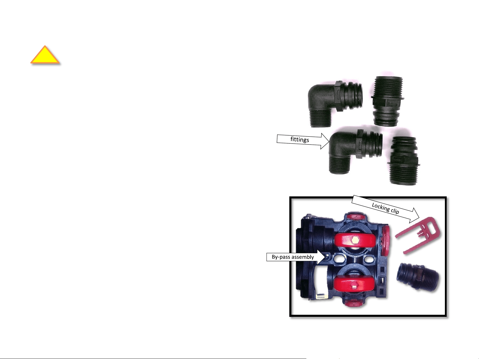
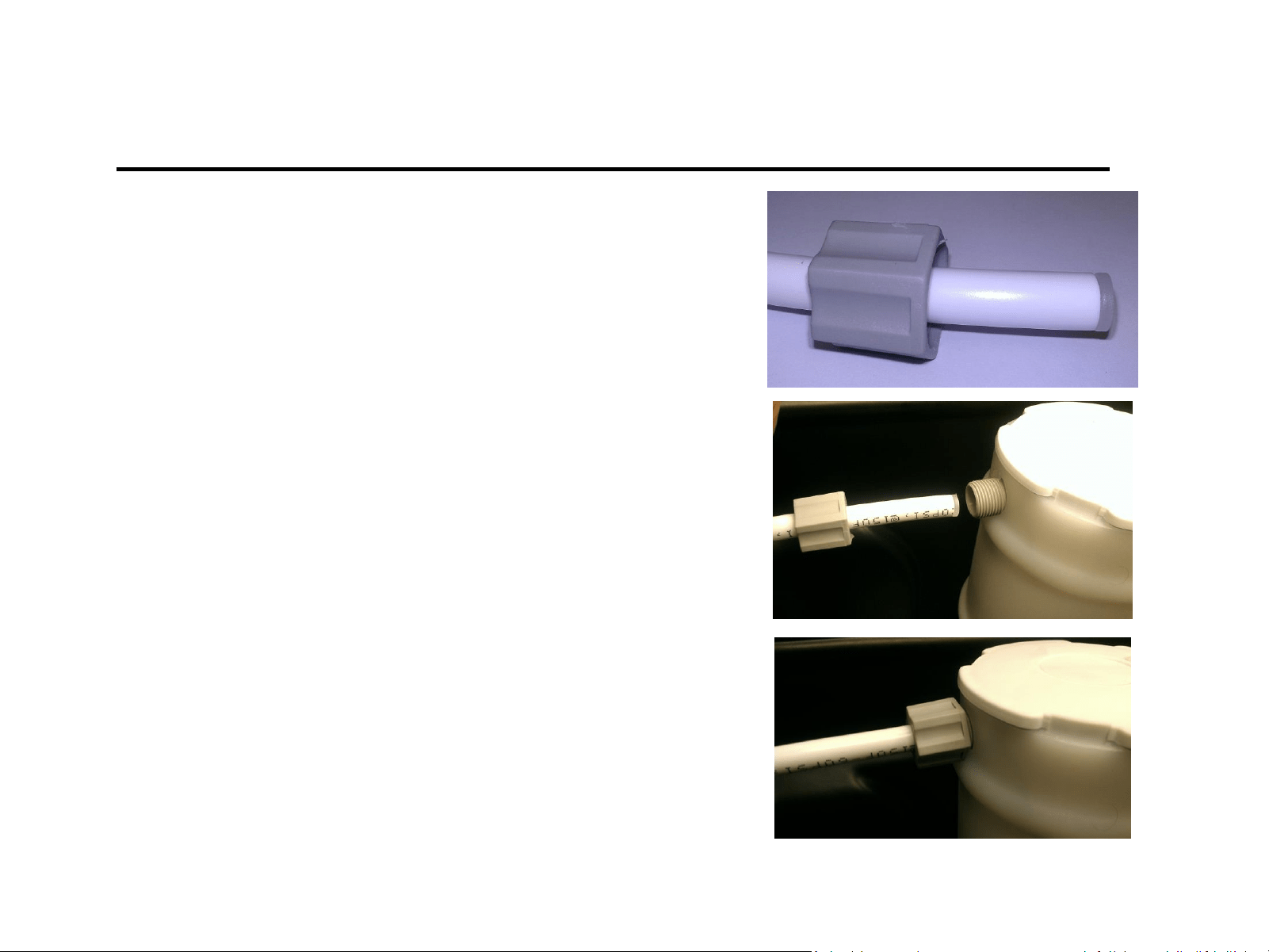
Important! - Be sure to lubricate the o-rings
on the quick connect fittings prior to installation.
3. Make final main water connections to the
valve, using quick connect fittings.
Includes:
(2) 3/4 “ male threaded 90 quick connect fitting
(2) 1” male threaded straight quick connect fitting
a) Install fittings on the by-pass by removing
the red locking clips.
b) Return the red locking clips to secure the
fitting
Plumbing Connections
Be sure to comply with all required plumbing codes.
Fig. 1
!
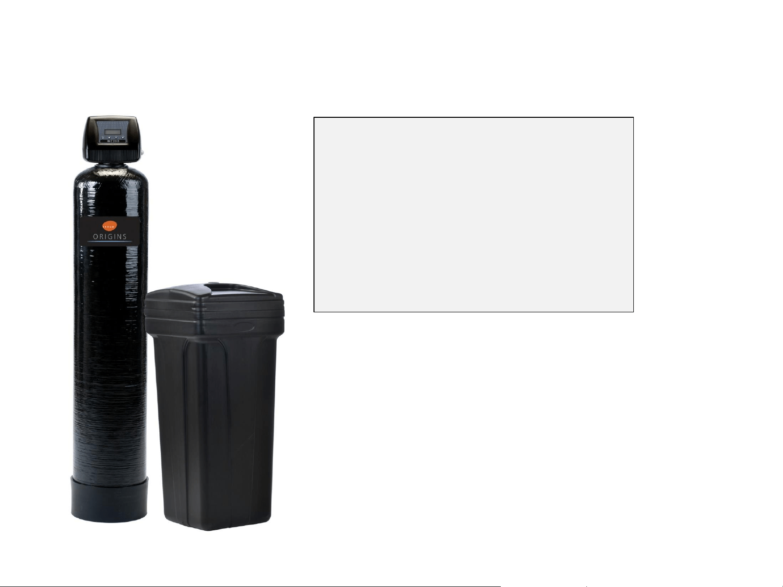
1850 Valve
(Metered for demand regeneration)
• By-pass valve is included and comes
with ¾” and 1” quick connect pipe
fittings
• Metered for demand regeneration
• Ideal for softeners, iron, sulfur,
carbon and sediment filters
• For tanks to 16” (softeners)
• For tanks to 10” (filters)
• Easy to program
• Operational data shown on LED,
including flow rate, last regeneration
date, gallons remaining and more
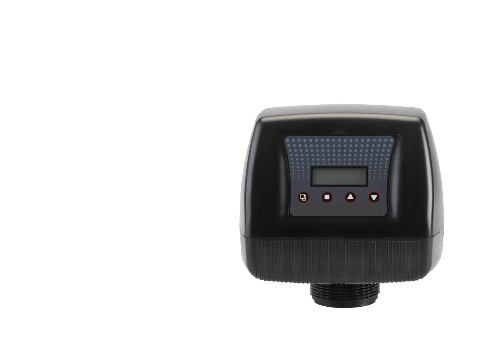
WC 100
Features
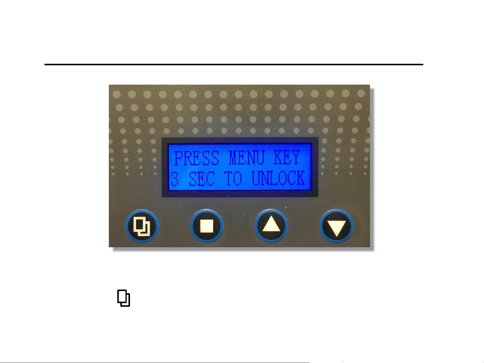
Valve Programming
Press and hold for 3 seconds to unlock the valve for programing.
FIRST - UNLOCK VALVE
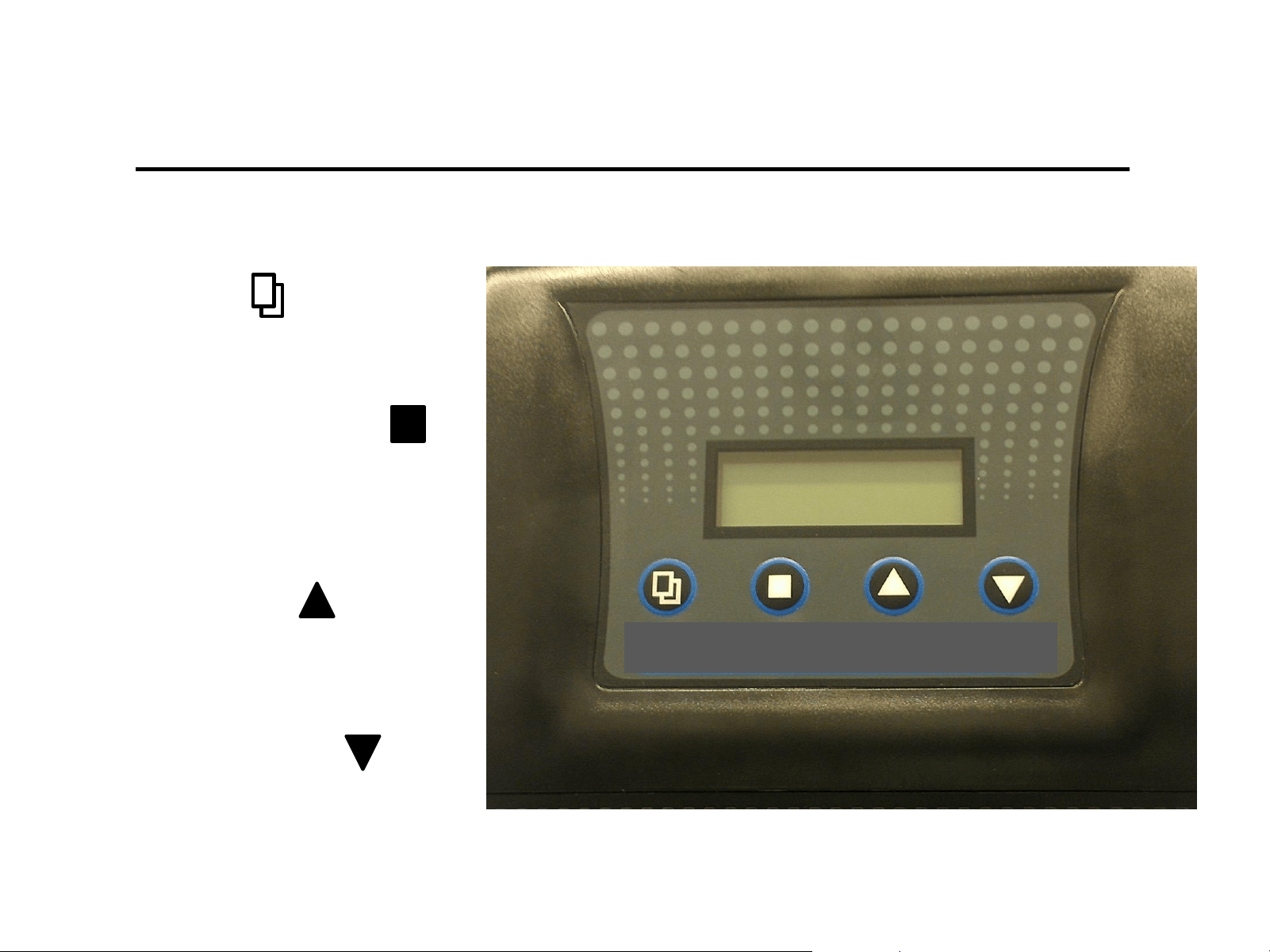
1) Menu Key
Press this key to enters or exit menu
Settings
Valve button programing control definitions
2) Set / Save Regen Key
Press this key to select a program
or to save a setting
3) Up arrow Key
Press these keys to go to the
previous menu
4) Down arrow Key
Press these keys to go to
the next menu
WC 100
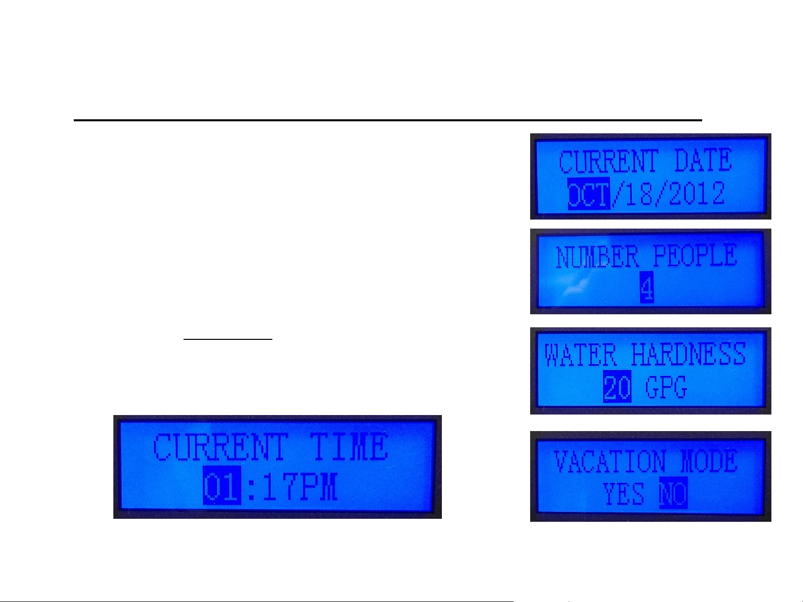
Level-I Set up Parameters
(Required for initial set-up)
Level-1
Time – Enter the time of valve set up.
Date - Enter Today’s date at time of valve set up.
Number of People – Enter # of full-time residence (default 4).
Water Hardness – Set it to your test results ( default 20 gpg).
Vacation Mode – default is no, changing this setting will
change the valve operation to a calendar cycle.
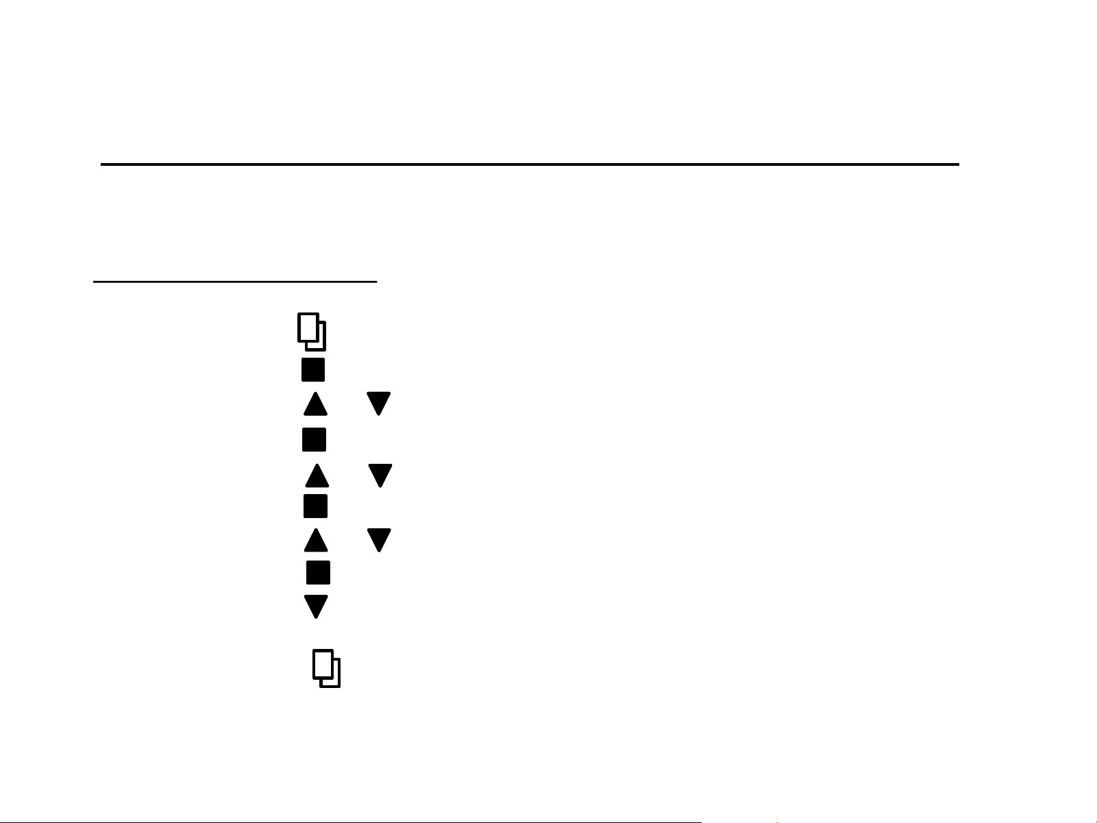
Time
1) Press * to enter menu (hour display will be highlighted)
2) Press to enter hour setting (must be flashing to edit)
3) Press or to adjust hour
4) Press to save and move to minute setting (flashing)
5) Press or to adjust minute
6) Press to save and move to AM/PM setting (flashing)
7) Press or to adjust AM/PM
8) Press to save and move to hour spot (not flashing)
9) Press to go to current date set up or to cycle through level I
settings (continue to set all level I setting)
10) Press * to exit menu and return to main screen
Making Adjustments – Level I
All programing is adjusted using the methods described in the programing method.
Setting level I programing
*Note: if valve is “locked” you will need to press and hold menu for 3 seconds. Valve will “beep” when
changing menu’s or parameters. Highlighted parameter must flash to be able to adjust setting.

Reasons to change Level-II setting (examples)
1) Initial start up configurations
2) Using tanks other than 9X48
3) Using Valve for Carbon or Iron Filter
4) Setting valve up for use in in Iron Filter
5) Adjusting any cycle or setting to enhance performance
Level-II Programming
(Settings have been pre-set at the factory)
These settings have been made at the factory and are held in memory. Level-II settings will
not be lost during a power outage. However, if adjustments are desired, follow the
directions below.
Level-II
• Language
• Valve operation
• Regen Mode
• Regen Time
• Capacity Calc.
• Resin Volume (FT3)
• Salt Settings (lbs./FT3)
• Refill Flow Rate (GPM)
• Unit Capacity (grains)
• Reserve Capacity
• Backwash (min)
• Brine/Rinse (min)
• Rapid Rinse (min)
• Refill (min)

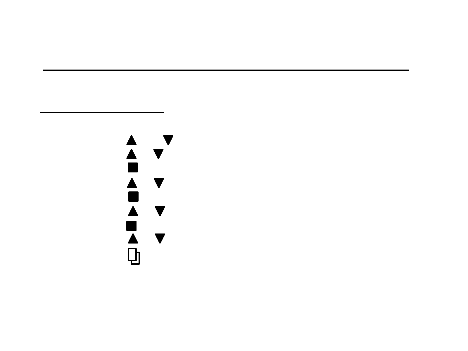
Backwash
1) Press and together to enter menu (5 sec.)
2) Press or scroll to backwash setting
3) Press to enter menu (flashing)
4) Press or to adjust minutes (flashing)
5) Press to save setting and advance to tenths of minute
6) Press or to adjust tenths of minute for backwash
7) Press to save
8) Press or to move to another menu
9) Press to exit menu and return to main screen
Making Adjustments – Level II
All programing is adjusted using the same methods as for Level-I programming.
Setting level II programing
*Note: If the valve is “locked” you will need to press and hold menu for 3 seconds. Valve will “beep” when
changing menus or parameters. Highlighted parameter will flash when you are able to adjust setting.
Note: Valve must be in manual mode to adjust and save capacity and refill duration.

Softener Settings
Level-II Parameters (factory settings)
Tank
Size
System
Language
Valve
Operation
Regen.
Mode
Regen.
Time
Resin
Volume
Carbon
Volume
Unit
Capacity
Reserve
Capacity
Backwash Brine/
Rinse
Rapid
Rinse
9X48 English
Softener
Meter
Delay
2:00
AM
1.00 None 30,000 75 10 60 10
12X52
Combo
English
Softener
Meter
Delay
2:00
AM
1.00 1.0 30,000 75 10 60 10
Factory settings: Capacity Calculation (AUTO), Refill Flow Rate (0.70 GPM), 10 lbs. salt settings.
All settings may be adjusted. However, to change the gallons capacity and re-fill, valve must be set
up in MANUAL MODE to save altered settings for these two fields.
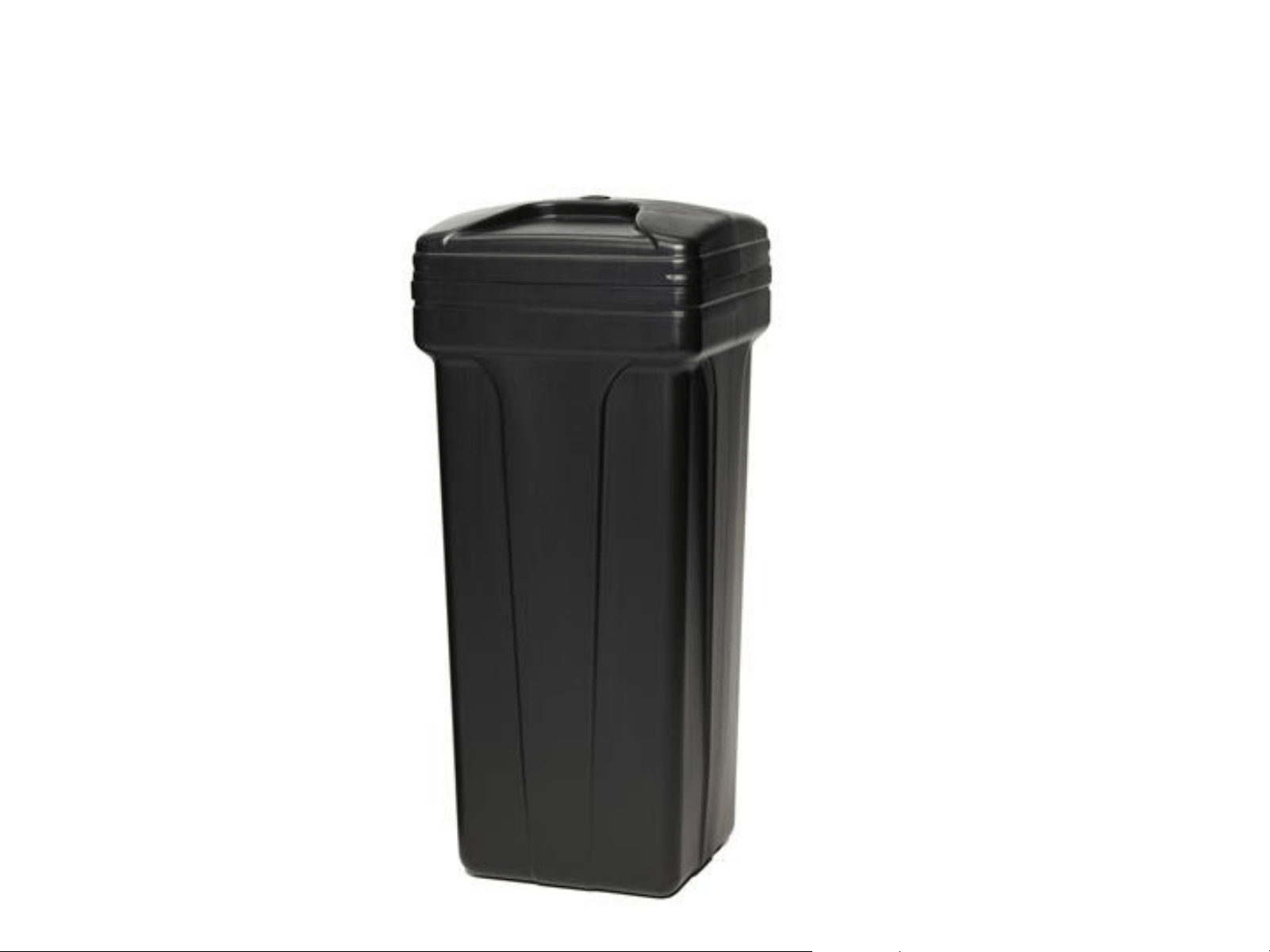
Brine Tank Installation
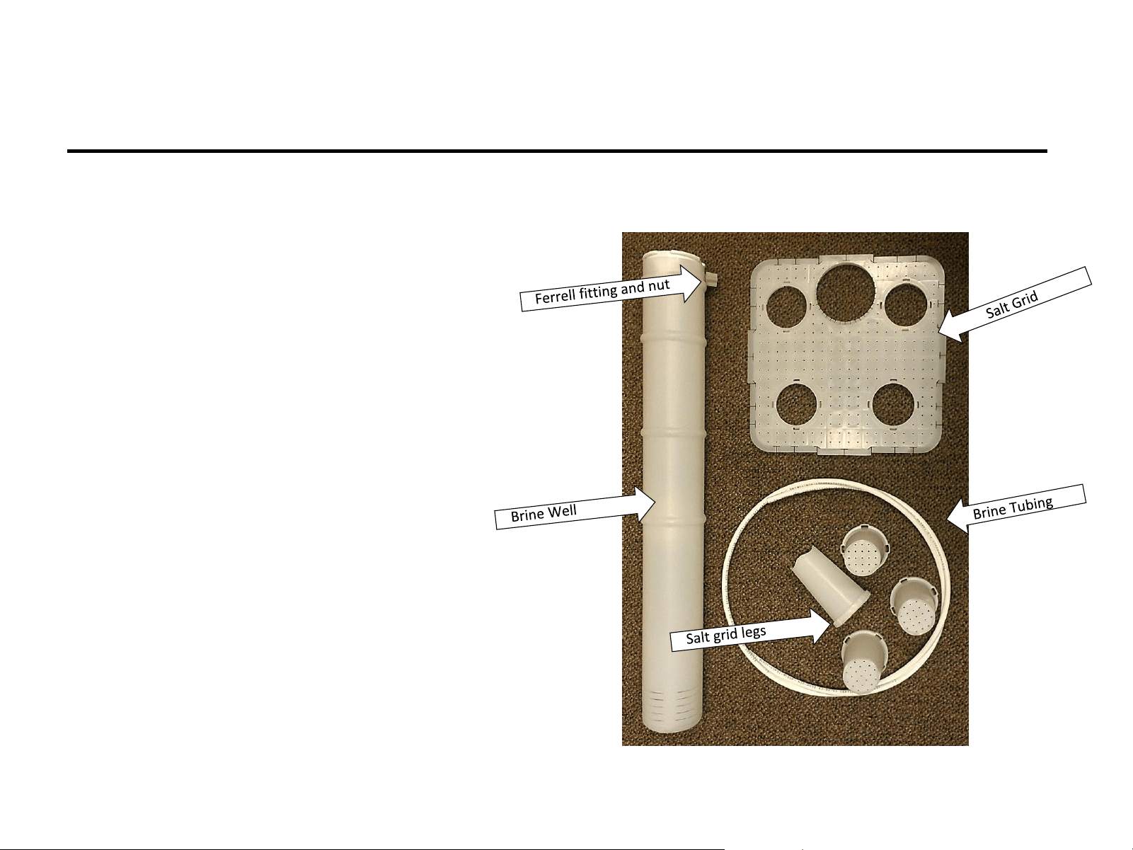
Brine Tank Components (Softeners)
3) Brine line Ferrell fitting and nut
1) Brine tank with cover
4) Salt grid with legs (4)
2) Brine well assembly
5) Brine line tubing (approx. 6 ft)
Brine tank components are packed in the brine tank.
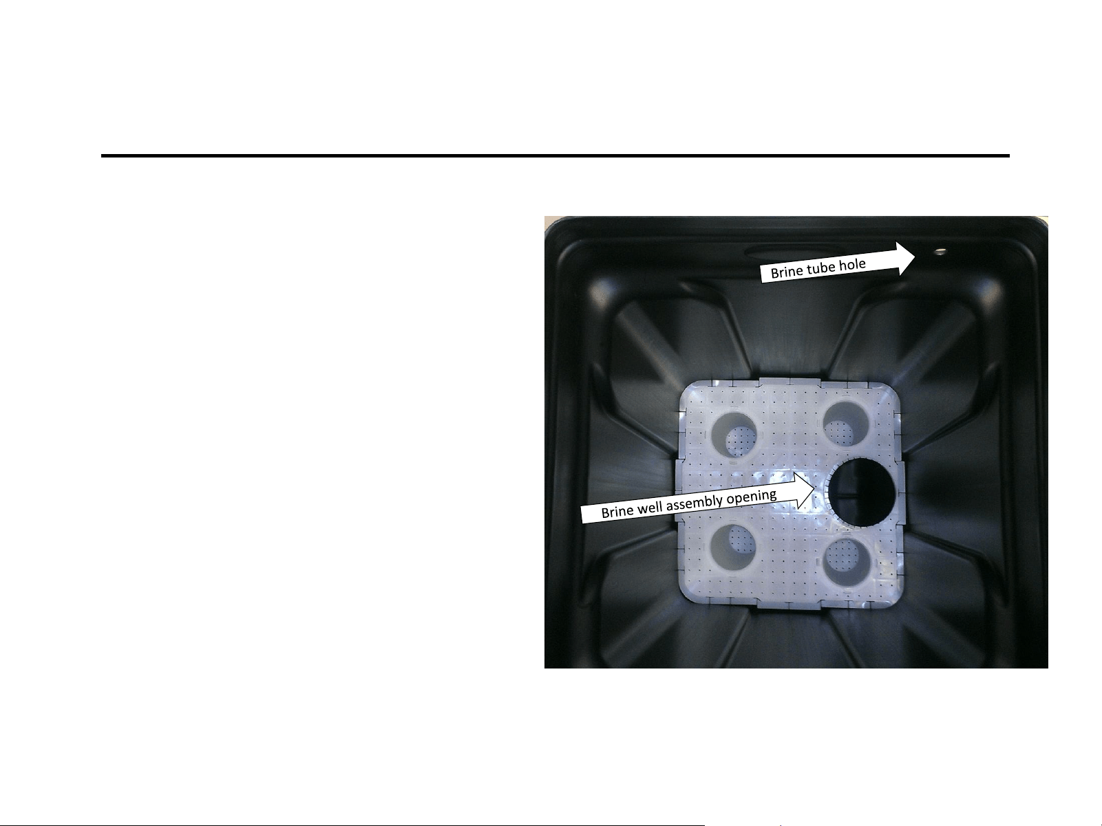
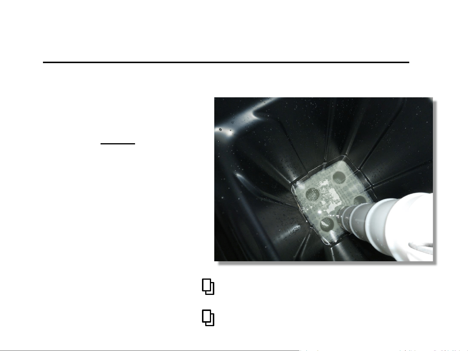
Installing the Salt Grid
1) Carefully line up the brine line
hole, in the side of the tank, with
the salt grid, so that the brine well
assembly will line up to the brine
line hole making it easier to plumb
without bending the tubing.
2) Insert assembled salt grid, legs
down.
3) Push the salt grid to the bottom of
the tank, the position tabs on the
outer edge of the salt grid make it
a tight fit to keep the grid from
floating if the tank runs out of salt.
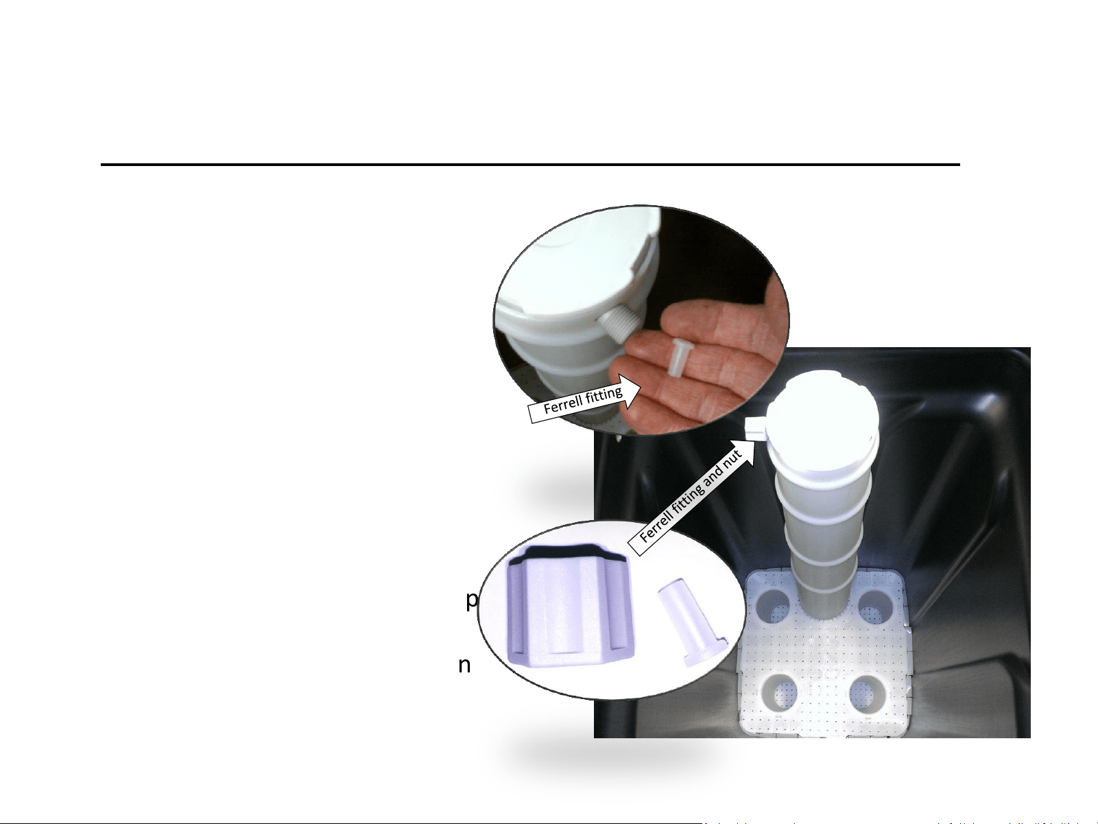
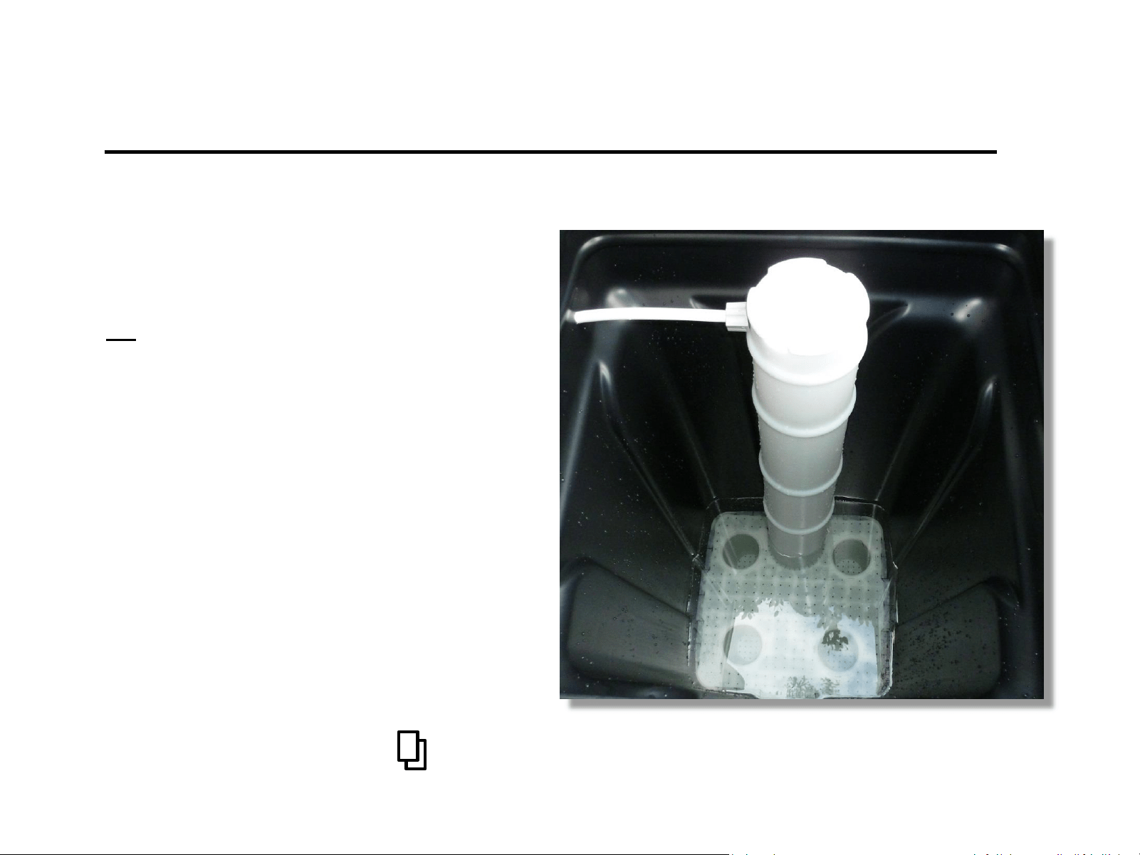
Installing the Brine Well
1) Remove nut and tube Ferrell
from brine well assembly.
(Ferrell is inside the brine well
tube connection)
Note: you may need to retrieve Ferrell
from inside fitting.
2) Insert brine well assembly into
tank, push to the bottom of
the tank.
3) Rotate the brine well to line up
the brine line hole in the tank
and the Ferrell nut connection
on the brine well assembly.
Connecting Brine Line
1) Feed brine line tube through the hole in
the side of the brine tank.
2) Place Ferrell nut on tube.
3) Insert Ferrell into brine line tubing.
4) Insert tubing w/ Ferrell into brine well
assembly.
Note: Removing the cap, to the brine well
assembly, and hold the threaded connection to
make is easier to get a good seal.
5) Hand tighten Ferrell nut to brine well
assembly.
Brine Tank is now ready to be connected for service – Do not add salt at this time!
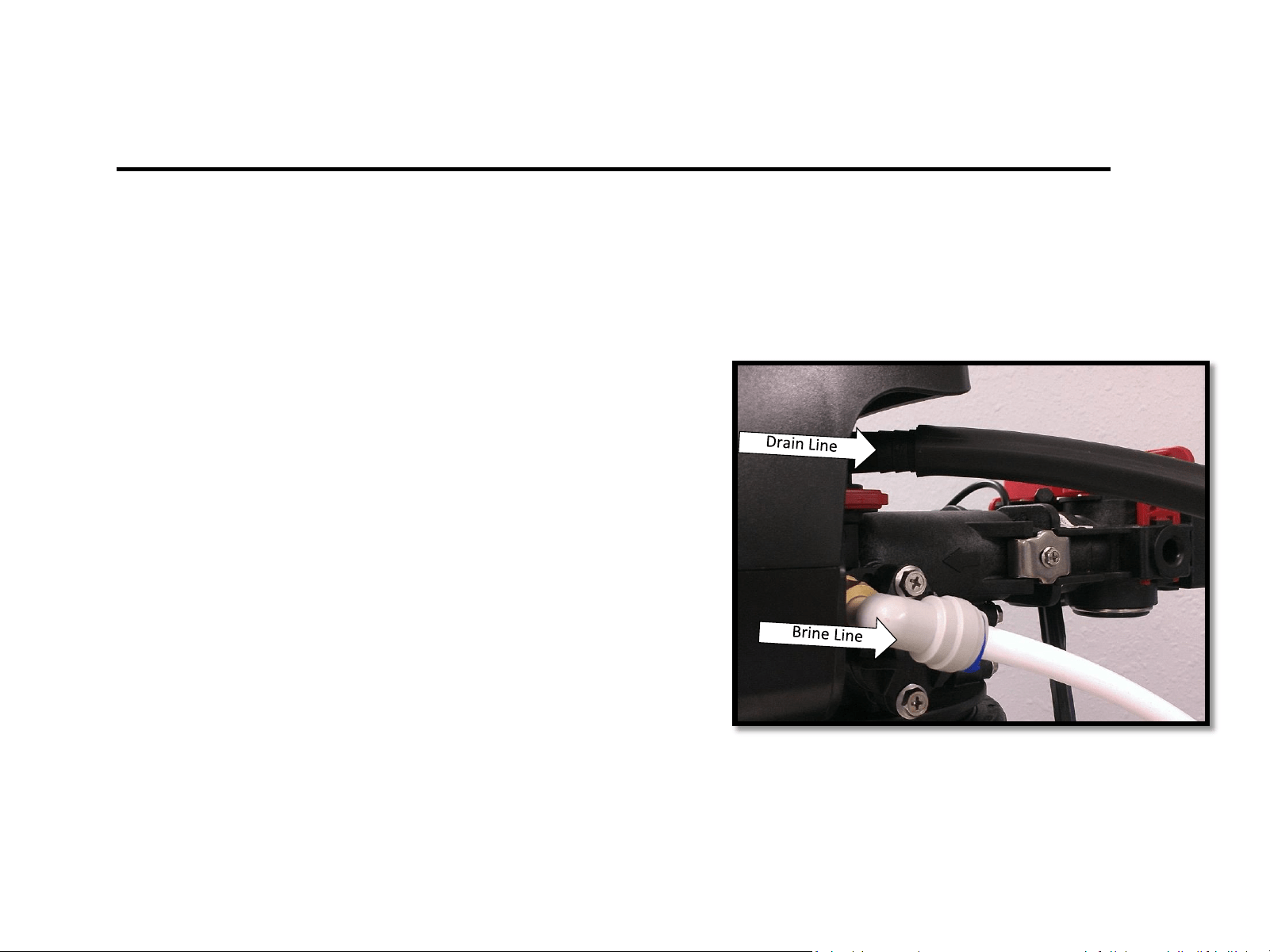
1) Connect drain Line to the valve
a) Slide drain line tube over barbed drain line
connection fitting until secured
2) Connect brine line to the valve.
a) Remove Blue collet clip
(hold on to it, it goes back)
b) Insert 3/8” tubing into John Guest fitting
c) Press tubing in again to ensure a good seal
d) Replace blue collet clip
Connect Brine & Drain Lines
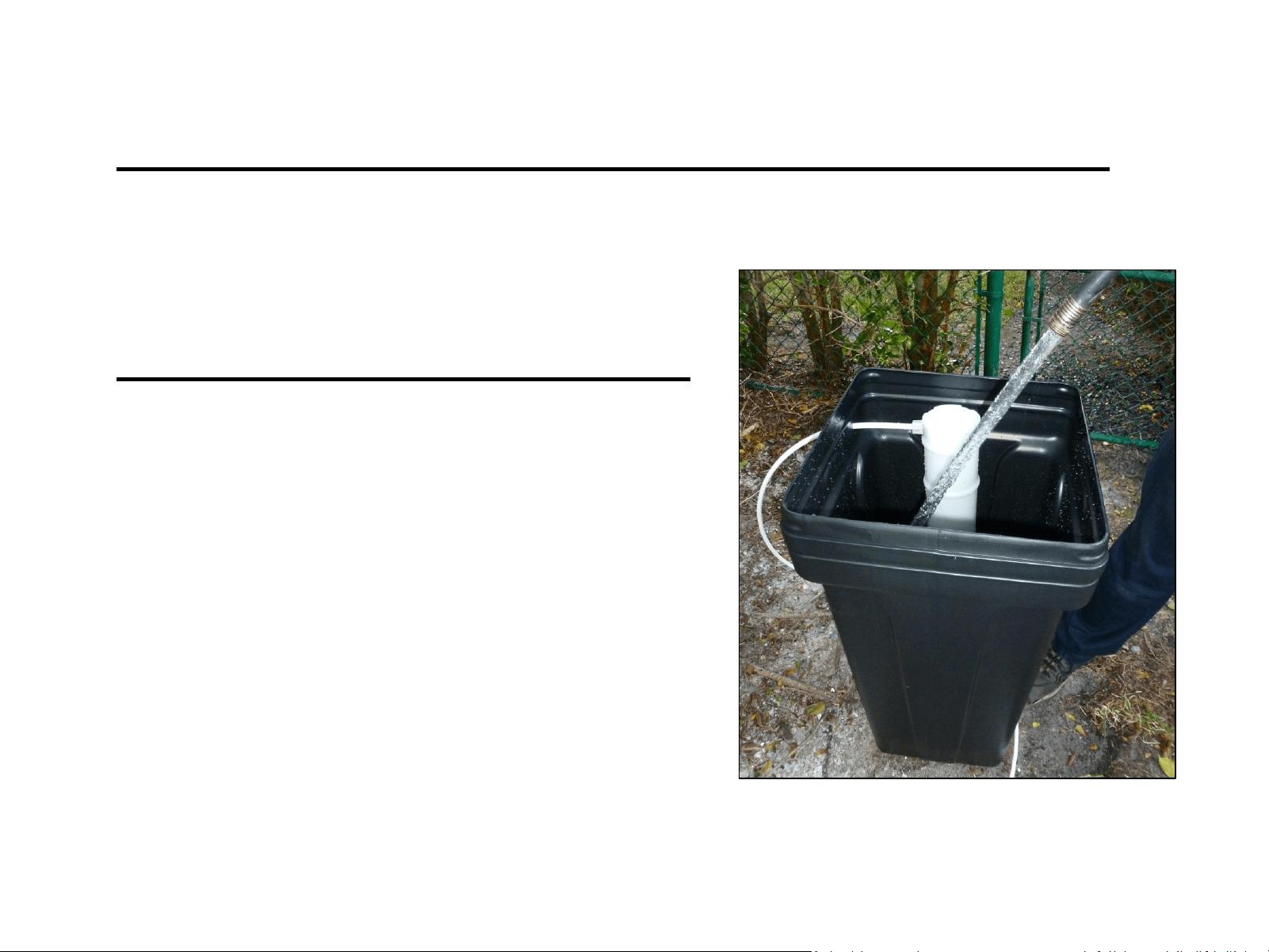
Add Water to the Brine Tank
DO NOT ADD SALT AT THIS POINT
Add only water to the brine tank
with a sanitary hose until water is
3” – 4” above the grid plate.
*If you are using a tank that does not have a grid
plate, fill water until it is above the air check in the
brine tank.
Be sure to have the brine tank in its final position before proceeding.
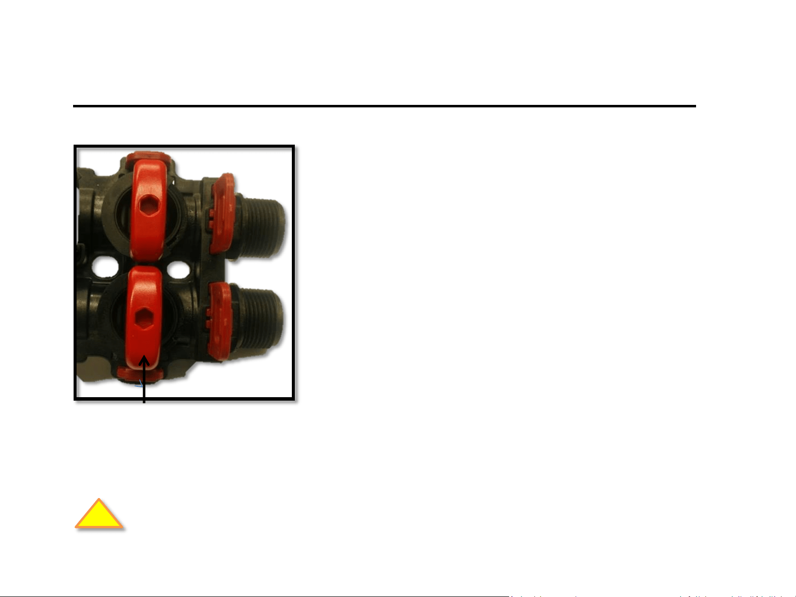
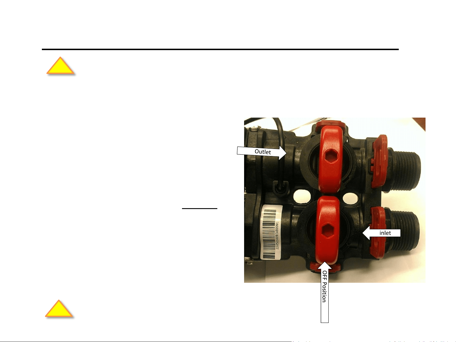
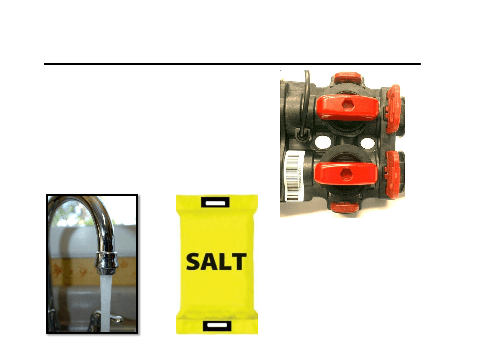
System Installation
OUT
Turn the by-pass valves to the “OFF” position
(red valves) pointing “across” the valve as
shown.
With the faucet still on, open the main water
supply valve.
IN
Off Position
CAUTION: Inspect all plumbing connections. Check for leaks and make repairs as needed.
!
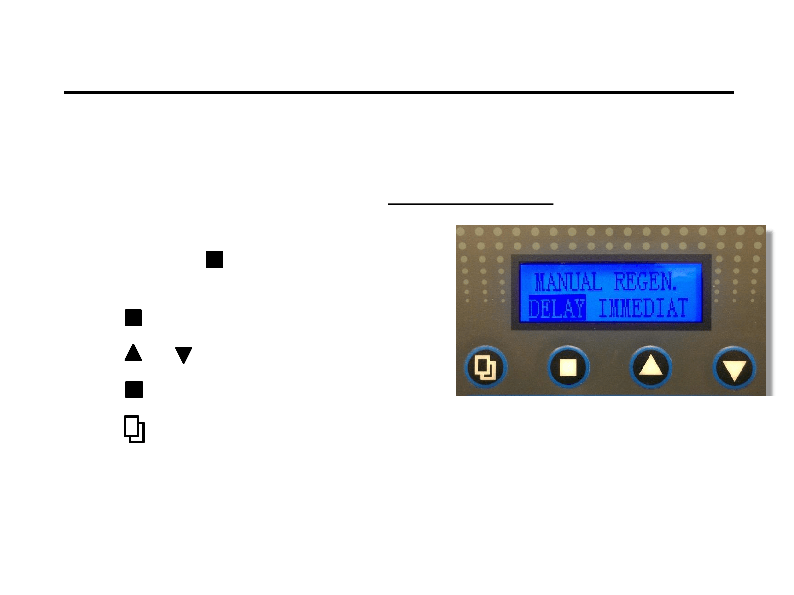
System Start Up
1) Press and hold to enter Manual Regen.
Mode. (press for 3-5 seconds)
2) Press to enter edit mode (flashing).
3) Press or to select immediate (flashing).
4) Press to save.
5) Press to show “Advancing to Backwash”.
Note: Valve will reset backwash cycle to delay after manual regen. cycle has finished.
Notice:
For initial start-up, the Inlet and Outlet valves on the bypass
should be in the closed position.
Fill the Mineral Tank
1) With bypass valves in the
“OFF” position turn on
the main water supply.
2) Open “Inlet” valve slowly
¼ turn clockwise to fill the
media tank. Continue to
open inlet all the way.
If the mineral tank was not filled, do so at this time following the directions below:
CAUTION: Allow time for glued connections to cure before proceeding.
!
CAUTION: Inspect all plumbing connections. Check for leaks and make repairs as needed.
!
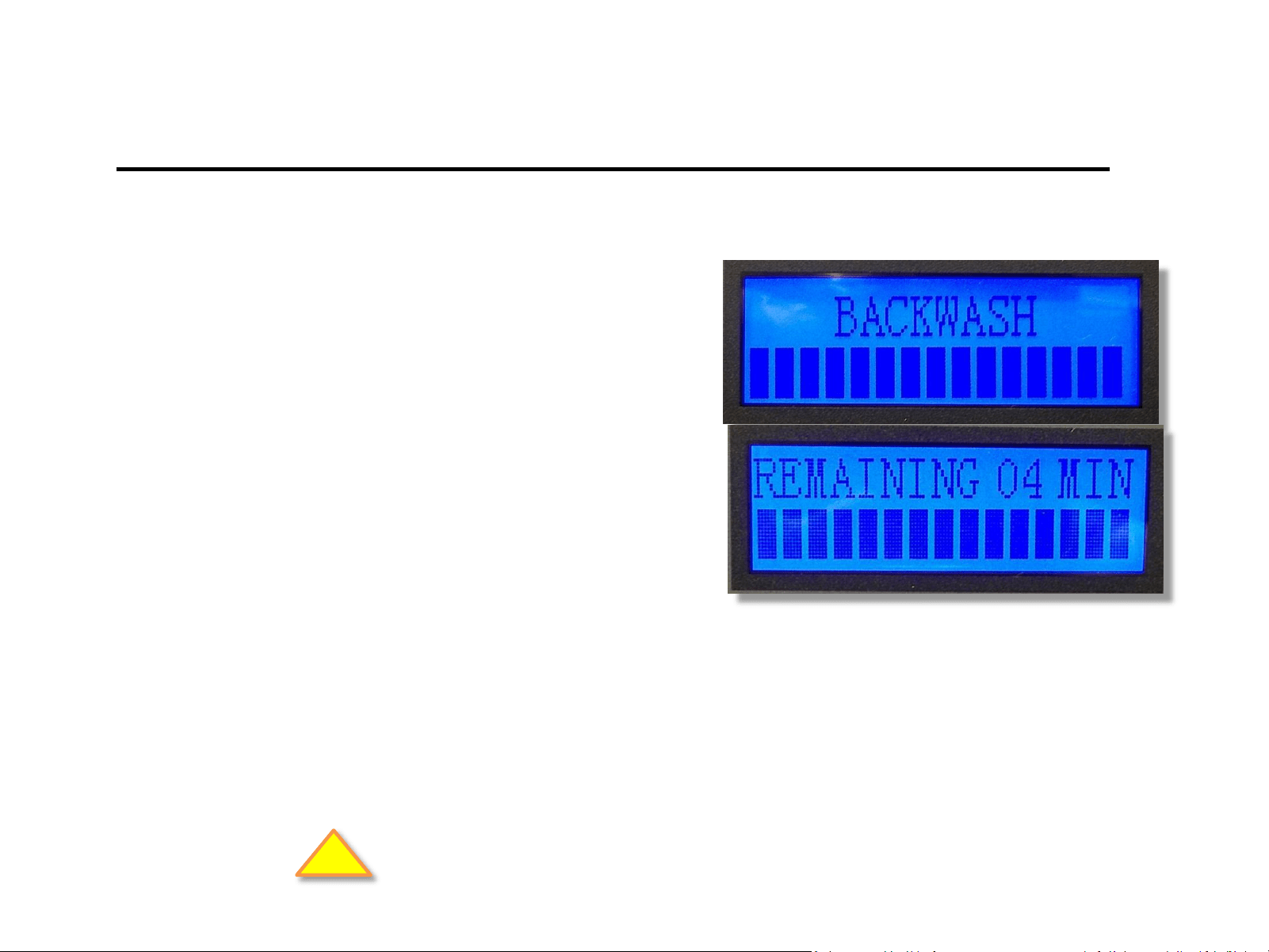
Start-Up In Backwash
1) Screen will now display
“Backwash” and flash
“Remaining XX min”
2) Run Backwash cycle until
drain line runs clear.
Inlet on by-pass is “open” – Outlet on by-pass is “closed”.
Note: Watch to see if the backwash flow rate is proper – do not obstruct drain
line. This is particularly important for Iron and Sulfur filters.
!
Check for leaks and repair as needed.
Note: When advancing to another cycle, valve will show “advancing to”. Once the valve is “in” a subsequent cycle,
you may press any button to advance to another cycle. Valve cannot be advanced in the “advancing to” position.
REPEAT of the initial backwash cycle may be required should the backwash
discharge water does not run “clear” after unit has finished the first cycle.
NOTE: It’s common to run multiple backwash cycles with Carbon and Iron
filters due to the amount of “fines” in the media.
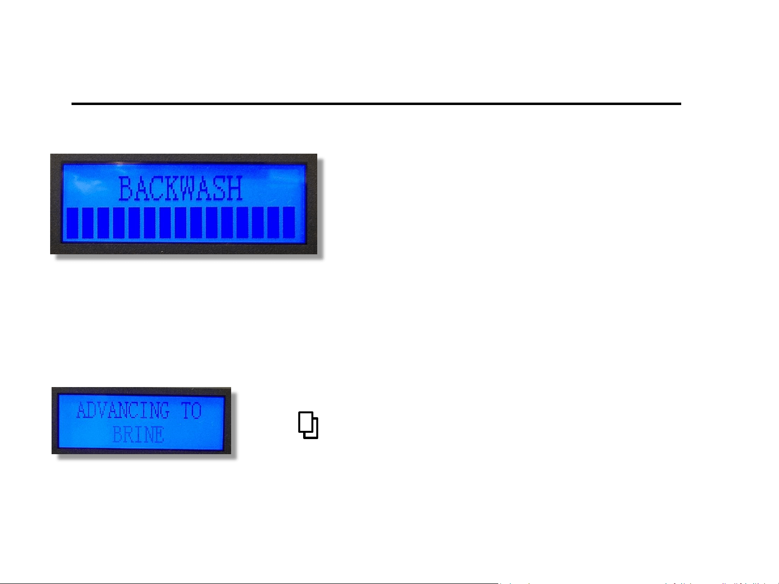
System Installation
Leave the system in backwash for a minimum
of five to ten minutes until the water runs
clear. This will flush loose particles from and
preservatives from the media.
Press to advance to the next cycle “Advancing to Brine”
Brine Rinse (Draw)
Press to go to “Advancing to Rinse”
Look for the water
level to drop in brine
tank.
NOTE: This is critical to
ensure proper operation.
(Hold the brine line to feel for flow)
Press to go to “Advancing to Refill”
Brine Tank Re-fill
Watch . . .
The water level in the brine tank go
up during refill.
Otherwise there will not be
sufficient brine water for the next
regeneration cycle (for softeners).
The water level should fill to 3” to
4” above the salt grid.
(Hold the brine line to feel for the flow)
Press to show “Advancing to Service”
Ready for Service
1) Slowly open outlet to supply
water to the house.
2) Open a faucet on the treated
water side in the house until
water runs clear.
Finally . . .
Add salt to the brine tank.
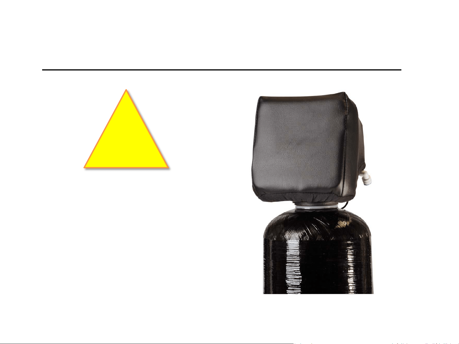
Weather Cover
(For outdoor installations)
WARNING
If the water treatment system is to be installed
outside, exposed to the weather and/or UV
Rays, it is necessary to install a weather cover
over the valve. The weather cover will protect
the valve from the damaging effects of UV
Rays on the LCD Screen and is required to
submit a warranty claim.
!