

Table of Contents
Installation ...................................................................................................................................................4
Get started....................................................................................................................................................5
.............................................................................................................................................................5
Find the device on the network.................................................................................................................5
Browser support ...............................................................................................................................5
Open the device's web interface................................................................................................................5
Create an administrator account...............................................................................................................5
Secure passwords....................................................................................................................................6
Make sure that no one has tampered with the device software ....................................................................6
Configure your device.....................................................................................................................................7
Configure air quality monitor ...................................................................................................................7
Configure the dashboard of the air quality sensor ...............................................................................7
Set the air quality sensor...................................................................................................................8
Download sensor data statistics .........................................................................................................8
Calibration for the first run of the device ............................................................................................9
Configure a profile ..................................................................................................................................9
Configure a profile with custom siren audio file...................................................................................9
Import or export a profile ................................................................................................................10
Set up direct SIP (P2P) ....................................................................................................................10
Set up SIP through a server (PBX) .....................................................................................................11
Set up rules for events ...........................................................................................................................11
Trigger an action ............................................................................................................................11
Record video when detects vaping....................................................................................................11
Play audio clip when CO2 is too high ................................................................................................12
Activate signaling LEDs and siren via PIR sensor.................................................................................12
Start a profile when an alarm is triggered .........................................................................................13
Start a profile through SIP...............................................................................................................13
Control more than one profile through SIP extensions ........................................................................13
Run two profiles with different priorities...........................................................................................14
Activate light and siren profile through HTTP post when a camera detects motion.................................15
Activate light and siren profile through virtual input when a camera detects motion .............................16
Activate light and siren profile over MQTT when camera detects motion ..............................................17
Send an email if a speaker test fails..................................................................................................18
Play custom clip when an alarm is triggered......................................................................................19
Stop audio with DTMF.....................................................................................................................20
Set up audio for incoming SIP calls...................................................................................................20
The web interface ........................................................................................................................................22
Status ..................................................................................................................................................22
Video ...................................................................................................................................................23
Stream ..........................................................................................................................................23
Air quality sensor ..................................................................................................................................24
Dashboard .....................................................................................................................................24
Settings.........................................................................................................................................28
Statistics .......................................................................................................................................29
Analytics ..............................................................................................................................................30
AXIS Audio analytics .......................................................................................................................30
Audio...................................................................................................................................................30
Device settings...............................................................................................................................30
Stream ..........................................................................................................................................31
Audio clips.....................................................................................................................................31
Audio enhancement........................................................................................................................31
Overview ..............................................................................................................................................32
Profiles ................................................................................................................................................32
AXIS D6310 Air Quality Sensor
2

Recordings ...........................................................................................................................................34
Media ..................................................................................................................................................35
Apps ....................................................................................................................................................35
System.................................................................................................................................................36
Time and location ...........................................................................................................................36
Network ........................................................................................................................................37
Security.........................................................................................................................................40
Accounts .......................................................................................................................................45
Events ...........................................................................................................................................47
MQTT ............................................................................................................................................51
SIP ................................................................................................................................................54
Storage .........................................................................................................................................59
Stream profiles...............................................................................................................................60
ONVIF............................................................................................................................................61
Detectors.......................................................................................................................................64
Power settings ...............................................................................................................................64
Accessories ....................................................................................................................................64
Logs ..............................................................................................................................................65
Plain config....................................................................................................................................66
Maintenance ........................................................................................................................................66
Maintenance..................................................................................................................................66
Troubleshoot ..................................................................................................................................67
Specifications..............................................................................................................................................68
Product overview ..................................................................................................................................68
....................................................................................................................................................68
Status LED............................................................................................................................................69
Buttons................................................................................................................................................69
Control button ...............................................................................................................................69
Microphone switch .........................................................................................................................69
Connectors ...........................................................................................................................................69
Network connector .........................................................................................................................69
I/O connector .................................................................................................................................69
RS485/RS422 connector..................................................................................................................70
Light pattern names ..............................................................................................................................71
Siren pattern names ..............................................................................................................................71
Clean your device.........................................................................................................................................73
Troubleshooting...........................................................................................................................................74
Reset to factory default settings .............................................................................................................74
Technical issues, clues, and solutions.......................................................................................................74
Performance considerations ...................................................................................................................75
Contact support ....................................................................................................................................75
AXIS D6310 Air Quality Sensor
3

4
Installation
Important
• Keep at least 1.5 meters (4.9 feet) away from areas with significant vents, or pollution sources. This
includes air vents, doors, windows, cooking areas etc.
• Install the device in a location that allows free air flow.
• For effective vaping or smoking detection, install the device on the ceiling at a height of 2.4–2.7 meters
(7.9–8.9 feet) from the floor.
• For effective air quality and environmental monitoring, install the device at a height of 0.9–1.8 meters
(3.0–5.9 feet) from the floor.
For detailed installation instructions, see the installation guide.
AXIS D6310 Air Quality Sensor

5
Get started
WARNING
Flashing or flickering lights can trigger seizures in persons with photosensitive epilepsy.
Find the device on the network
To find Axis devices on the network and assign them IP addresses in Windows®, use AXIS IP Utility or
AXIS Device Manager. Both applications are free and can be downloaded from axis.com/support.
For more information about how to find and assign IP addresses, go to How to assign an IP address and access
your device.
Browser support
You can use the device with the following browsers:
Chrome
TM
Edge
TM
Firefox
®
Safari
®
Windows
®
✓ ✓ * *
macOS
®
✓ ✓ * *
Linux
®
✓ ✓ * *
Other operating
systems
* * * *
✓: Recommended
*: Supported with limitations
Open the device's web interface
1. Open a browser and type the IP address or host name of the Axis device.
If you do not know the IP address, use AXIS IP Utility or AXIS Device Manager to find the device on the
network.
2. Type the username and password. If you access the device for the first time, you must create an
administrator account. See .
For descriptions of all the controls and options in the device’s web interface, see .
Create an administrator account
The first time you log in to your device, you must create an administrator account.
1. Enter a username.
2. Enter a password. See .
3. Re-enter the password.
4. Accept the license agreement.
5. Click Add account.
Important
The device has no default account. If you lose the password for your administrator account, you must reset
the device. See .
AXIS D6310 Air Quality Sensor

6
Secure passwords
Important
Use HTTPS (which is enabled by default) to set your password or other sensitive configurations over the
network. HTTPS enables secure and encrypted network connections, thereby protecting sensitive data, such
as passwords.
The device password is the primary protection for your data and services. Axis devices do not impose a password
policy as they may be used in various types of installations.
To protect your data we strongly recommend that you:
• Use a password with at least 8 characters, preferably created by a password generator.
• Don’t expose the password.
• Change the password at a recurring interval, at least once a year.
Make sure that no one has tampered with the device software
To make sure that the device has its original AXIS OS, or to take full control of the device after a security attack:
1. Reset to factory default settings. See .
After the reset, secure boot guarantees the state of the device.
2. Configure and install the device.
AXIS D6310 Air Quality Sensor

7
Configure your device
Configure air quality monitor
Configure the dashboard of the air quality sensor
On the device webpage, go to Air quality monitor > Dashboard:
• To edit the name of the dashboard, click on the left.
• To show data on the dashboard, click Edit >
.
AXIS D6310 Air Quality Sensor

8
• To hide data on the dashboard, Click Edit >
.
Set the air quality sensor
On the device webpage, go to Air quality sensor > Settings.
• Set thresholds of temperature, humidity, CO2, NOx, PM1.0, PM2.5, PM4.0, PM10.0, VOC, and AQI, see .
• Set temperature units, see .
• Set vaping detect sensitivity, see .
• Set storage retention time, see .
• Set cloud metadata frequency, see .
• Set the validation period, see .
Download sensor data statistics
You can export up to 365 days of sensor statistics to a CSV file for use in applications such as Microsoft® Excel.
1. On the device webpage, go to Air quality monitor > Statistics > Sensor Data Statistics.
AXIS D6310 Air Quality Sensor

9
2. Choose a date range:
– Custom range: In the From and To lists, select the start and end dates (up to 365 days).
– Predefined range: In the Predefined date range list, select an available period.
Note
If both a custom and a predefined range are selected, the custom range takes precedence.
Note
The maximum download range is limited by the retention time configured in .
3. In the Source list, select the desired source; to export data for all sources, click Download all data.
4. Click Download data to export the selected statistics.
Note
Click Download all data to export data for all sources within the chosen time span.
Calibration for the first run of the device
Note
• Full CO2 accuracy takes 2 days the first time the device runs.
• The AQI (Air Quality Index) requires 12 hours to be functional the first time the device runs. The AQI will
show Calculating until it has enough data. The calibration time is required whenever the device reboots.
• Full VOC accuracy is obtained after the device has been running for one hour. The calibration time is
required whenever the device reboots.
• Full NOx accuracy is obtained after the device has been running for 6 hours. The calibration time is
required whenever the device reboots.
Configure a profile
A profile is a collection of set configurations. You can have up to 30 profiles with different priorities and
patterns.
To set a new profile:
1. Go to Profiles and click Create.
2. Enter a Name and Description.
3. Select the Light and Siren settings that you want for your profile.
4. Set the light and siren Priority and click Save.
To edit a profile, click and select Edit.
Configure a profile with custom siren audio file
You can configure a profile with a custom audio file. You can save audio files up to 100 Mb in size on the
device. For larger audio files, use an SD card, if the device is equipped with an SD card slot.
Upload an audio file:
1. Go to Media and click Add.
2. Browse to select the file from your computer.
3. Select Storage location.
4. Click Save.
To use the audio file in a profile:
AXIS D6310 Air Quality Sensor

10
1. Go to Profiles and create a profile. Fore more information, see .
2. When configuring Siren, select the uploaded audio file as Pattern.
Import or export a profile
If you want to use a profile with predefined configurations, you can import it:
1. Go to Profiles and click Import.
2. Browse to locate the file or drag and drop the file that you want to import.
3. Click Save.
To copy one or more profiles and save to other devices, you can export them:
1. Select the profiles.
2. Click Export.
3. Browse to locate the .json files.
Set up direct SIP (P2P)
Use peer-to-peer when the communication is between a few user agents within the same IP network and there
is no need for extra features that a PBX-server could provide. To better understand how P2P works, see .
For more information about setting options, see .
1. Go to System > SIP > SIP settings and select Enable SIP.
2. To allow the device to receive incoming calls, select Allow incoming calls.
3. Under Call handling, set the timeout and duration for the call.
4. Under Ports, enter the port numbers.
– SIP port – The network port used for SIP communication. The signaling traffic through this port
is non-encrypted. The default port number is 5060. Enter a different port number if required.
– TLS port – The network port used for encrypted SIP communication. The signaling traffic
through this port is encrypted with Transport Layer Security (TLS). The default port number is
5061. Enter a different port number if required.
– RTP start port – Enter the port used for the first RTP media stream in a SIP call. The default start
port for media transport is 4000. Some firewalls might block RTP traffic on certain port numbers.
A port number must be between 1024 and 65535.
5. Under NAT traversal, select the protocols you want to enable for NAT traversal.
Note
Use NAT traversal when the device is connected to the network from behind a NAT router or a firewall. For
more information see .
6. Under Audio, select at least one audio codec with the desired audio quality for SIP calls. Drag-and-drop
to change the priority.
7. Under Additional, select additional options.
– UDP-to-TCP switching – Select to allow calls to switch transport protocols from UDP (User
Datagram Protocol) to TCP (Transmission Control Protocol) temporarily. The reason for switching
is to avoid fragmentation, and the switch can take place if a request is within 200 bytes of the
maximum transmission unit (MTU) or larger than 1300 bytes.
– Allow via rewrite – Select to send the local IP address instead of the router's public IP address.
– Allow contact rewrite – Select to send the local IP address instead of the router's public IP
address.
AXIS D6310 Air Quality Sensor

11
– Register with server every – Set how often you want the device to register with the SIP server
for the existing SIP accounts.
– DTMF payload type – Changes the default payload type for DTMF.
8. Click Save.
Set up SIP through a server (PBX)
Use a PBX-server when user agents will communicate within and outside the IP network. Additional features
could be added to the setup depending on the PBX-provider. To better understand how P2P works, see .
For more information about setting options, see .
1. Request the following information from your PBX provider:
– User ID
– Domain
– Password
– Authentication ID
– Caller ID
– Registrar
– RTP start port
2. To add a new account, go to System > SIP > SIP accounts and click + Account.
3. Enter the details you received from your PBX provider.
4. Select Registered.
5. Select a transport mode.
6. Click Save.
7. Set up the SIP settings the same way as for peer-to-peer. See for more information.
Set up rules for events
To learn more, check out our guide Get started with rules for events.
Trigger an action
1. Go to System > Events and add a rule. The rule defines when the device will perform certain actions.
You can set up rules as scheduled, recurring, or manually triggered.
2. Enter a Name.
3. Select the Condition that must be met to trigger the action. If you specify more than one condition for
the rule, all of the conditions must be met to trigger the action.
4. Select which Action the device should perform when the conditions are met.
Note
If you make changes to an active rule, the rule must be turned on again for the changes to take effect.
Record video when detects vaping
The following example explains how to set up an air quality sensor to record video to the network storage when
the air quality sensor detects vaping.
1. In the air quality sensor’s webpage, go to Settings > System > Storage to check that the network
storage is set.
2. Go to Settings > System > Events and add a rule. Enter the following information:
AXIS D6310 Air Quality Sensor

12
– Name: Type a name for the rule.
– Condition: Air quality monitor > Vaping or smoking detected.
– Action: Recordings > Record video.
– Storage: Network storage. Make sure the network storage is set.
– Camera: Select a camera view area.
– Stream profile: Select a stream profile or Create a stream profile.
– Prebuffer and Postbuffer: Set the desired values.
3. Click Save.
Play audio clip when CO2 is too high
This example explains how to play audio clip when CO2 is too high.
Create a rule
1. On the webpage, go to Events > Rules > Add a rule to create a rule.
2. Enter the following information:
– Name: Type a name for the rule.
– Conditions: Air quality monitor > Air quality outside acceptable range
– Sensor: CO2
– Action: Play audio clip
– Clip: select an audio clip.
3. Click Save.
Set up the alarm range for CO2
• In the webpage, go to Air quality monitor > Settings > CO2.
• Enter MIN and MAX data to set the CO2 range.
Activate signaling LEDs and siren via PIR sensor
This example explains how to activate signaling LEDs and siren via PIR sensor. See for the positions of the
signaling LEDs and siren.
Create a signaling LED and siren profile:
1. On the device webpage, go to Profiles > Create.
2. Enter the following information:
– Name: Profile 1
– Description: Add the profile description.
– Light : Select Pattern, Speed, Intensity, Color and Duration.
– Siren: Select Pattern, Intensity and Duration.
Note
Profiles with higher numbers have a higher priority.
– Priority: Select Light priority and Siren priority.
Create an event :
1. Go to System > Events > Rules and add a rule.
2. Enter the following information:
– Name: Activate signaling LEDs and siren
– Condition: PIR sensor
AXIS D6310 Air Quality Sensor

13
– Action: Run light and siren profile
– Profile: Profile 1
– Action: Start
3. Click Save.
Start a profile when an alarm is triggered
This example explains how to trigger an alarm when the digital input signal is changed.
Set direction input for the port:
1. Go to System > Accessories > I/O ports.
2. Go to Port 1 > Normal state and click Circuit closed.
Create a rule:
1. Go to System > Events and add a rule.
2. Type a name for the rule.
3. In the list of conditions, select I/O > Digital input is active.
4. Select Port 1.
5. In the list of actions, select Run light and siren profile while the rule is active.
6. Select the profile you want to start.
7. Click Save.
Start a profile through SIP
This example explains how to trigger an alarm through SIP.
Activate SIP:
1. Go to System > SIP > SIP settings.
2. Select Enable SIP and Allow incoming calls.
3. Click Save.
Create a rule:
1. Go to System > Events and add a rule.
2. Type a name for the rule.
3. In the list of conditions, select Call > State.
4. In the list of state, select Active.
5. In the list of actions, select Run light and siren profile while the rule is active.
6. Select the profile you want to start.
7. Click Save.
Control more than one profile through SIP extensions
Activate SIP:
1. Go to System > SIP > SIP settings.
2. Select Enable SIP and Allow incoming calls.
3. Click Save.
Create a rule to start a profile:
AXIS D6310 Air Quality Sensor

14
1. Go to System > Events and add a rule.
2. Type a name for the rule.
3. In the list of conditions, select Call > State change.
4. In the list of reasons, select Accepted by device.
5. In Call direction, select Incoming.
6. In Local SIP URI, type sip:[Ext]@[IP address] where [Ext] is the extension used for the profile and [IP
7. In the list of actions, select Light and Siren > Run light and siren profile.
8. Select the profile you want to start.
9. Select the action Start.
10. Click Save.
Create a rule to stop a profile:
1. Go to System > Events and add a rule.
2. Type a name for the rule.
3. In the list of conditions, select Call > State change.
4. In the list of reasons, select Terminated.
5. In Call direction, select Incoming.
6. In Local SIP URI, type sip:[Ext]@[IP address] where [Ext] is the extension used for the profile and [IP
7. In the list of actions, select Light and Siren > Run light and siren profile.
8. Select the profile you want to stop.
9. Select the action Stop.
10. Click Save.
Repeat the steps to create start and stop rules for each profile you want to control through SIP.
Run two profiles with different priorities
If you run two profiles with different priorities, the profile with a higher priority number will interrupt the
profile with a lower priority number.
Note
If you run two profiles with the same priority, the most recent profile will cancel the previous one.
This example explains how to set the device to show one profile with priority 4 over another profile with priority
3 when triggered by the digital I/O port.
Create profiles:
1. Create a profile with priority 3.
2. Create another profile with priority 4.
Create a rule:
1. Go to System > Events and add a rule.
2. Type a name for the rule.
3. In the list of conditions, select I/O > Digital input is active.
4. Select a port.
5. In the list of actions, select Run light and siren profile while the rule is active.
6. Select the profile that has the highest priority number.
AXIS D6310 Air Quality Sensor

15
7. Click Save.
8. Go to Profiles and start the profile with the lowest priority number.
Activate light and siren profile through HTTP post when a camera detects motion
This example explains how to connect a camera to the air quality sensor, and activate a light and siren profile in
the air quality sensor whenever the application AXIS Motion Guard, installed in the camera, detects motion.
Before you start:
• Create a new user with the role Operator or Administrator in the air quality sensor.
• Create a profile in the air quality sensor called: “Light and siren profile”.
• Set up AXIS Motion Guard in the camera and create a profile called: “Camera profile”.
• Make sure to use AXIS Device Assistant with firmware version 10.8.0 or later.
Create a recipient in the camera:
1. In the camera’s device interface, go to System > Events > Recipients and add a recipient.
2. Enter the following information:
– Name: air quality sensor
– Type: HTTP
– URL: http://<IPaddress>/axis-cgi/siren_and_light.cgi
Replace <IPaddress> with the address of the air quality sensor.
– The username and password of the newly created air quality sensor user.
3. Click Test to make sure all data is valid.
4. Click Save.
Create two rules in the camera:
1. Go to Rules and add a rule.
2. Enter the following information:
– Name: Activate air quality sensor with motion
– Condition: Applications > Motion Guard: Camera profile
– Action: Notifications > Send notification through HTTP
– Recipient: air quality sensor.
The information must be the same as you previously entered under Events > Recipients > Name.
– Method: Post
– Body:
{ "apiVersion": "1.0", "method": "start", "params": {
"profile" : "Light and siren profile" } }
Make sure to enter the same information under ‘"profile" : <>’ as you did when you created the profile in the
air quality sensor, in this case: “Light and siren profile”.
3. Click Save.
4. Add another rule with the following information:
– Name: Deactivate air quality sensor with motion
– Condition: Applications > Motion Guard: Camera profile
– Select Invert this condition.
– Action: Notifications > Send notification through HTTP
– Recipient: air quality sensor
The information must be the same as you previously entered under Events > Recipients > Name.
– Method: Post
AXIS D6310 Air Quality Sensor

16
– Body:
{ "apiVersion": "1.0", "method": "stop", "params": { "profile" : "Light and siren
profile" } }
Make sure to enter the same information under ‘"profile" : <>’ as you did when you created the profile in the
air quality sensor, in this case: “Light and siren profile”.
5. Click Save.
Activate light and siren profile through virtual input when a camera detects motion
This example explains how to connect a camera to the air quality sensor, and activate a profile in the air quality
sensor whenever the application AXIS Motion Guard, installed in the camera, detects motion.
Before you start:
• Create a new account with Operator or Administrator privileges in air quality sensor.
• Create a profile in air quality sensor. See .
• Set up AXIS Motion Guard in the camera and create a profile called “Camera profile”.
Create two recipients in the camera:
1. In the camera’s device interface, go to System > Events > Recipients and add a recipient.
2. Enter the following information:
– Name: Activate virtual port
– Type: HTTP
– URL: http://<IPaddress>/axis-cgi/virtualinput/activate.cgi
Replace <IPaddress> with the address of the air quality sensor.
– The account and password of the newly created air quality sensor account.
3. Click Test to make sure all data is valid.
4. Click Save.
5. Add a second recipient with the following information:
– Name: Deactivate virtual port
– Type: HTTP
– URL: http://<IPaddress>/axis-cgi/virtualinput/deactivate.cgi
Replace <IPaddress> with the address of the air quality sensor.
– The account and password of the newly created air quality sensor account.
6. Click Test to make sure all data is valid.
7. Click Save.
Create two rules in the camera:
1. Go to Rules and add a rule.
2. Enter the following information:
– Name: Activate virtual IO1
– Condition: Applications > Motion Guard: Camera profile
– Action: Notifications > Send notification through HTTP
– Recipient: Activate virtual port
– Query string suffix: schemaversion=1&port=1
3. Click Save.
4. Add another rule with the following information:
– Name: Deactivate virtual IO1
– Condition: Applications > Motion Guard: Camera profile
AXIS D6310 Air Quality Sensor

17
– Select Invert this condition.
– Action: Notifications > Send notification through HTTP
– Recipient: Deactivate virtual port
– Query string suffix: schemaversion=1&port=1
5. Click Save.
Create a rule in the air quality sensor:
1. In the air quality sensor web interface, go to System > Events and add a rule.
2. Enter the following information:
– Name: Trigger on virtual input 1
– Condition: I/O > Virtual input is active
– Port: 1
– Action: Light and siren > Run light and siren profile while the rule is active
– Profile: select the newly created profile
3. Click Save.
Activate light and siren profile over MQTT when camera detects motion
This example explains how connect a camera to the air quality sensor, and activate a profile in the air quality
sensor whenever the camera detects motion.
Before you start:
• Create a profile in the air quality sensor.
• Set up an MQTT broker and get the broker’s IP address, username and password.
• Make sure the motion detection application is configured and running in the camera.
Set up the MQTT client in the camera:
1. In the camera’s web interface, go to System > MQTT > MQTT client > Broker and enter the following
information:
– Host: Broker IP address
– Client ID: For example Camera 1
– Protocol: The protocol the broker is set to
– Port: The port number used by the broker
– The broker Username and Password
2. Click Save and Connect.
Create two rules in the camera for MQTT publishing:
1. Go to System > Events > Rules and add a rule.
2. Enter the following information:
– Name: Motion detected
– Condition: Applications > Motion alarm
– Action: MQTT > Send MQTT publish message
– Topic: Motion
– Payload: On
– QoS: 0, 1 or 2
3. Click Save.
4. Add another rule with the following information:
– Name: No motion
AXIS D6310 Air Quality Sensor

18
– Condition: Applications > Motion alarm
– Select Invert this condition.
– Action: MQTT > Send MQTT publish message
– Topic: Motion
– Payload: Off
– QoS: 0, 1 or 2
5. Click Save.
Set up the MQTT client in the air quality sensor:
1. In the air quality sensor web interface, go to System > MQTT > MQTT client > Broker and enter the
following information:
– Host: Broker IP address
– Client ID: Siren 1
– Protocol: The protocol the broker is set to
– Port: The port number used by the broker
– Username and Password
2. Click Save and Connect.
3. Go to MQTT subscriptions and add a subscription.
Enter the following information:
– Subscription filter: Motion
– Subscription type: Stateful
– QoS: 0, 1 or 2
4. Click Save.
Create a rule in the air quality sensor for MQTT subscriptions:
1. Go to System > Events > Rules and add a rule.
2. Enter the following information:
– Name: Motion detected
– Condition: MQTT > Stateful
– Subscription filter: Motion
– Payload: On
– Action: Light and siren > Run light and siren profile while the rule is active
– Profile: Select the profile you want to be active.
3. Click Save.
Send an email if a speaker test fails
In this example the audio device is configured to send an email to a defined recipient when a speaker test fails.
The speaker test is configured to be performed 18:00 every day.
1. Set up a schedule for the speaker test:
1.1. Go to the device interface > System > Events > Schedules.
1.2. Create a schedule that starts at 18:00 and ends at 18:01 every day. Name it "Daily at 6pm".
2. Create an email recipient:
2.1. Go to the device interface > System > Events > Recipients.
2.2. Click Add recipient.
2.3. Name the recipient "Speaker test recipients"
AXIS D6310 Air Quality Sensor

19
2.4. Under Type, select Email.
2.5. Under Send email to, enter the email addresses of the recipients. Use commas to separate
multiple addresses.
2.6. Enter the details for the email account of the sender.
2.7. Click Test to send a test email.
Note
Some email providers have security filters that prevent users from receiving or viewing large attachments,
from receiving scheduled emails and similar. Check the email provider’s security policy to avoid delivery
problems and locked email accounts.
2.8. Click Save.
3. Set up the automated speaker test:
3.1. Go to the device interface > System > Events > Rules.
3.2. Click Add a rule.
3.3. Enter a name for the rule.
3.4. Under Condition, select Schedule and select from the trigger list
3.5. Under Schedule, select your schedule (“Daily at 6pm”).
3.6. Under Action, select Run automatic speaker test.
3.7. Click Save.
4. Set up the condition for sending an email when the speaker test fails:
4.1. Go to the device interface > System > Events > Rules.
4.2. Click Add a rule.
4.3. Enter a name for the rule.
4.4. Under Condition, select Speaker test result.
4.5. Under Speaker test status, select Didn’t pass the test.
4.6. Under Action, select Send notification to email.
4.7. Under Recipient, select your recipient (“Speaker test recipients”)
4.8. Enter a subject and a message, and click Save.
Play custom clip when an alarm is triggered
This example explains how to trigger a custom audio file when the digital input signal changes.
Upload an audio file:
1. Go to Media and click Add.
2. Click to browse and select the audio file from your computer.
3. Select Storage location.
4. Click Save.
Create a profile with the audio file:
1. Go to Profiles and click Create.
2. Enter Name and select light pattern for the profile.
3. In the siren section, select the uploaded audio file.
4. Select Intensity and Duration.
5. Click Save.
AXIS D6310 Air Quality Sensor

20
Set direction input for the port:
1. Go to System > Accessories > I/O ports.
2. Go to Port 1 > Normal state and click Circuit closed.
Create a rule:
1. Go to System > Events and add a rule.
2. Enter a name for the rule.
3. In the list of conditions, select I/O > Digital input is active.
4. Select Port 1.
5. In the list of actions, select Run light and siren profile while the rule is active.
6. Select the profile with the uploaded audio file.
7. Click Save.
Stop audio with DTMF
This example explains how to:
• Configure DTMF on a device.
• Set up an event to stop the audio when a DTMF command is sent to the device.
1. Go to System > SIP > SIP settings.
2. Make sure Enable SIP is turned on.
If you need to turn it on, remember to click Save afterwards.
3. Go to SIP accounts.
4. Next to the SIP account, click > Edit.
5. Under DTMF, click + DTMF sequence.
6. Under Sequence, enter "1".
7. Under Description, enter "stop audio".
8. Click Save.
9. Go to System > Events > Rules and click + Add a rule.
10. Under Name, enter "DTMF stop audio".
11. Under Condition, select DTMF.
12. Under DTMF Event ID, select stop audio.
13. Under Action, select Stop playing audio clip.
14. Click Save.
Set up audio for incoming SIP calls
You can set up a rule that plays an audio clip when you receive a SIP call.
You can also set up an additional rule that answers the SIP call automatically after the audio clip has ended.
This can be useful in cases where an alarm operator wants to call the attention of someone near an audio device
and establish a line of communication. This is done by making a SIP call to the audio device, which will play an
audio clip to alert the persons near the audio device. When the audio clip has stopped playing, the SIP call is
automatically answered by the audio device and communication between the alarm operator and the persons
near the audio device can take place.
Enable SIP settings:
1. Go to the device interface of the speaker, by entering its IP address in a web browser.
2. Go to System > SIP > SIP settings and select Enable SIP.
AXIS D6310 Air Quality Sensor

21
3. To allow the device to receive incoming calls, select Allow incoming calls.
4. Click Save.
5. Go to SIP accounts.
6. Next to the SIP account, click > Edit.
7. Uncheck Answer automatically.
Play audio when a SIP call is received:
1. Go to Settings > System > Events > Rules and add a rule.
2. Type a name for the rule.
3. In the list of conditions, select State.
4. In the list of states, select Ringing.
5. In the list of actions, select Play audio clip.
6. In the list of clips, select the audio clip you want to play.
7. Select how many times to repeat the audio clip. 0 means “play once”.
8. Click Save.
Answer the SIP call automatically after the audio clip has ended:
1. Go to Settings > System > Events > Rules and add a rule.
2. Type a name for the rule.
3. In the list of conditions, select Audio clip playing.
4. Check Use this condition as a trigger.
5. Check Invert this condition.
6. Click + Add a condition to add a second condition to the event.
7. In the list of conditions, select State.
8. In the list of states, select Ringing.
9. In the list of actions, select Answer call.
10. Click Save.
AXIS D6310 Air Quality Sensor
22
The web interface
To reach the device’s web interface, type the device’s IP address in a web browser.
Status
Device info
Shows the device information, including AXIS OS version and serial number.
Upgrade AXIS OS: Upgrade the software on your device. Takes you to the Maintenance page where you can
do the upgrade.
Time sync status
Shows NTP synchronization information, including if the device is in sync with an NTP server and the time
remaining until the next sync.
NTP settings: View and update the NTP settings. Takes you to the Time and location page where you can
change the NTP settings.
Security
Shows what kind of access to the device that is active, what encryption protocols are in use, and if unsigned
apps are allowed. Recommendations to the settings are based on the AXIS OS Hardening Guide.
Hardening guide: Link to AXIS OS Hardening guide where you can learn more about cybersecurity on Axis
devices and best practices.
Locate device
Shows the locate device information, including serial number and IP address.
Locate device: Plays a sound that helps you identify the speaker. For some products, the device will flash a
LED.
Power status
Shows power status information. Information varies depending on the product.
Ongoing recordings
Shows ongoing recordings and their designated storage space.
Recordings: View ongoing and filtered recordings and their source. For more information, see
Shows the storage space where the recording is saved.
Connected clients
Shows the number of connections and connected clients.
View details: View and update the list of connected clients. The list shows IP address, protocol, port, state,
and PID/process of each connection.
AXIS D6310 Air Quality Sensor
23
Video
Stream
General
Resolution: Select the image resolution suitable for the surveillance scene. A higher resolution increases
bandwidth and storage.
Frame rate: To avoid bandwidth problems on the network or reduce storage size, you can limit the frame rate
to a fixed amount. If you leave the frame rate at zero, the frame rate is kept at the highest possible rate under
the current conditions. A higher frame rate requires more bandwidth and storage capacity.
P-frames: A P-frame is a predicted image that shows only the changes in the image from the previous frame.
Enter the desired number of P-frames. The higher the number, the less bandwidth is required. However, if
there is network congestion, there could be a noticeable deterioration in the video quality.
Compression: Use the slider to adjust the image compression. High compression results in a lower bitrate and
lower image quality. Low compression improves the image quality, but uses more bandwidth and storage
when you record.
Signed video : Turn on to add the signed video feature to the video. Signed video protects the video from
tampering by adding cryptographic signatures to the video.
Bitrate control
• Average: Select to automatically adjust the bitrate over a longer time period and provide the best
possible image quality based on the available storage.
– Click to calculate the target bitrate based on available storage, retention time, and
bitrate limit.
– Target bitrate: Enter desired target bitrate.
– Retention time: Enter the number of days to keep the recordings.
– Storage: Shows the estimated storage that can be used for the stream.
– Maximum bitrate: Turn on to set a bitrate limit.
– Bitrate limit: Enter a bitrate limit that is higher than the target bitrate.
• Maximum: Select to set a maximum instant bitrate of the stream based on your network bandwidth.
– Maximum: Enter the maximum bitrate.
• Variable: Select to allow the bitrate to vary based on the level of activity in the scene. More activity
requires more bandwidth. We recommend this option for most situations.
Audio
Include: Turn on to use audio in the video stream.
Source : Select what audio source to use.
Stereo : Turn on to include built-in audio as well as audio from an external microphone.
AXIS D6310 Air Quality Sensor

24
Air quality sensor
Dashboard
Real-time sensor data
Shows the real-time sensor data.
Note
• Full CO2 accuracy takes 2 days the first time the device runs.
• The AQI (Air Quality Index) requires 12 hours to be functional the first time the device runs. The AQI will
show Calculating until it has enough data. The calibration time is required whenever the device reboots.
• Full VOC accuracy is obtained after the device has been running for one hour. The calibration time is
required whenever the device reboots.
• Full NOx accuracy is obtained after the device has been running for 6 hours. The calibration time is
required whenever the device reboots.
AXIS D6310 Air Quality Sensor

25
: Click to set the name of the dashboard.
Edit: Click to show or hide the data.
: Click to add data to the dashboard.
AXIS D6310 Air Quality Sensor

26
: Click to remove data from the dashboard.
Temperature: View the real-time temperature from the air quality sensor.
Humidity: View the real-time humidity from the air quality sensor.
CO2: View the real-time carbon dioxide.
The color meanings of the CO2 status bars are as follows:
• Green (0-1000): Good. The data is considered satisfactory.
• Orange (1001-2000): Unhealthy for sensitive group. Members of sensitive groups may experience
health effects. The general public is less likely to be affected.
• Red (2001-5000): Unhealthy. Everyone may begin to experience health effects; members of sensitive
groups may experience more serious health effects.
• Purple (5001-40000): Very unhealthy. Health warnings of emergency conditions. The entire
population is more likely to be affected.
NOx: View the real-time nitric oxide and nitrogen dioxide.
The color meanings of the NOx status bars are as follows:
AXIS D6310 Air Quality Sensor

27
• Green (0-30): Good. The data is considered satisfactory.
• Yellow (31-150): Moderate. The data is acceptable. There may be a moderate health concern for a
very small number of people who are unusually sensitive.
• Orange (151-300): Unhealthy for sensitive group. Everyone may begin to experience health effects;
members of sensitive groups may experience more serious health effects.
• Red (301-500): Unhealthy. Everyone may begin to experience health effects; members of sensitive
groups may experience more serious health effects.
PM 1.0: View the real-time particle matter 1.0.
PM 2.5: View the real-time particle matter 2.5.
The color meanings of the PM 2.5 status bars are as follows:
• Green (0-9): Good. The data is considered satisfactory.
• Yellow (9.1-35.4): Moderate. The data is acceptable. There may be a moderate health concern for a
very small number of people who are unusually sensitive.
• Orange (35.5-55.4): Unhealthy for sensitive group. Everyone may begin to experience health
effects; members of sensitive groups may experience more serious health effects.
• Red (55.5-125.4): Unhealthy. Everyone may begin to experience health effects; members of sensitive
groups may experience more serious health effects.
• Purple (125.5-225.4): Very unhealthy. Health warnings of emergency conditions. The entire
population is more likely to be affected.
• Maroon (225.5-1000): Hazardous. Emergency conditions. The entire population is more likely to be
affected.
PM 4.0: View the real-time particle matter 4.0.
PM 10.0: View the real-time particle matter 10.0.
The color meanings of the PM 10.0 status bars are as follows:
• Green (0-54): Good. The data is considered satisfactory.
• Yellow (55-154): Moderate. The data is acceptable. There may be a moderate health concern for a
very small number of people who are unusually sensitive.
• Orange (155-254): Unhealthy for sensitive group. Everyone may begin to experience health effects;
members of sensitive groups may experience more serious health effects.
• Red (255-354): Unhealthy. Everyone may begin to experience health effects; members of sensitive
groups may experience more serious health effects.
• Purple (355-424): Very unhealthy. Health warnings of emergency conditions. The entire population
is more likely to be affected.
• Maroon (425-1000): Hazardous. Emergency conditions. The entire population is more likely to be
affected.
Vaping/Smoking: View the vaping or smoking detected or undetected.
The color meanings of the Vaping/Smoking status bars are as follows:
• Green: Undetected. The suspected vaping or smoking activity is not detected.
• Red: Detected. The suspected vaping or smoking activity is detected.
VOC: View volatile organic compounds index.
The color meanings of the VOC status bars are as follows:
• Green (0-100): Good. The data is considered satisfactory.
• Yellow (101-300): Moderate. The data is acceptable. There may be a moderate health concern for a
very small number of people who are unusually sensitive.
AXIS D6310 Air Quality Sensor

28
• Orange (301-400): Unhealthy for sensitive group. Everyone may begin to experience health effects;
members of sensitive groups may experience more serious health effects.
• Red (401-500): Unhealthy. Everyone may begin to experience health effects; members of sensitive
groups may experience more serious health effects.
AQI: View air quality index.
The color meanings of the air quality index status bars are as follows:
• Green (0-50): Good. The data is considered satisfactory.
• Yellow (51-100): Moderate. The data is acceptable. There may be a moderate health concern for a
very small number of people who are unusually sensitive.
• Orange (101-150): Unhealthy for sensitive group. Everyone may begin to experience health effects;
members of sensitive groups may experience more serious health effects.
• Red (151-200): Unhealthy. Everyone may begin to experience health effects; members of sensitive
groups may experience more serious health effects.
• Purple (201-300): Very unhealthy. Health warnings of emergency conditions. The entire population
is more likely to be affected.
• Maroon (301-500): Hazardous. Emergency conditions. The entire population is more likely to be
affected.
Settings
Threshold
Sets up the air quality sensor data.
Temperature: Set temperature MIN and MAX within the range -10 to 45.
Humidity: Set humidity MIN and MAX within the range 0 to 100.
CO2: Set carbon dioxide MIN and MAX within the range 0 to 40000.
NOx: Set nitric oxide and nitrogen dioxide MIN and MAX within the range 0 to 500.
PM1.0: Set particle matter 1.0 MIN and MAX within the range 0 to 1000.
PM2.5: Set particle matter 2.5 MIN and MAX within the range 0 to 1000.
PM4.0: Set particle matter 4.0 MIN and MAX within the range 0 to 1000.
PM10.0: Set particle matter MIN and MAX within the range 0 to 1000.
VOC: Set volatile organic compounds index MIN and MAX within the range 0 to 500.
AQI: Set air quality index MIN and MAX within the range 0 to 500.
Temperature units
Show temperature in : Celsius or Fahrenheit
Vaping Detect Sensitivity
Sets up the vaping detect sensitivity.
Low sensitivity, High sensitivity : Use the slider to adjust the difference between low sensitivity and high
sensitivity at which the device should generate an alarm. High sensitivity means the device will detect even
small amounts of smoking or vaping and is more likely to trigger an alert; low sensitivity means it will only
respond to larger amounts of smoking or vaping, reducing the chance of false alarms.
AXIS D6310 Air Quality Sensor

29
Storage setting
• Retention time 1 month, frequency 1s: Your data is collected every second and retained for the latest
30 days only.
• Retention time 3 month, frequency 5s: Your data is collected every 5 seconds and retained for the
latest 90 days only.
• Retention time 1 year, frequency 10s: Your data is collected every 10 seconds and retained for the
latest 365 days only.
Note
Changing the Storage option will erase existing data.
Cloud metadata frequency
Cloud metadata frequency is used by third-party platforms that want to subscribe to sensor metadata with an
adjustable transmission frequency. The cloud metadata includes all the sensor data shown on the dashboard.
Cloud metadata: Turn on to use cloud metadata.
Note
By default this function is disabled; no metadata for the topic is sent. After enabling, metadata for the
topic is transmitted at the frequency range set below.
Set frequency range (00:00:01 - 23:59:59): Enter a value to set the frequency range.
Validation period
You can set a validation period for below air quality settings. The validation period acts as a time threshold, and
the reading must stay above the limit of the validation period range to trigger an alarm.
Example
If CO₂ validation period is 5 s, the CO₂ level must stay above the limit for the full 5 s to trigger the alarm.
Set validation period range (0s-60s) for the below data:
• Temperature
• Humidity
• CO2
• NOx
• PM1.0
• PM2.5
• PM4.0
• PM10.0
• VOC
• AQI
• Vaping/Smoking
Statistics
Sensor data statistics
You can export up to 365 days of sensor statistics to a CSV file for use in applications such as Microsoft® Excel.
AXIS D6310 Air Quality Sensor
30
• Predefined date range: to select the pre defined date range you’d like to download from the list.
• From and To: to select customized range you’d like to download. You can download the data up to 365
days.
Note
If both a custom and a predefined range are selected, the custom range takes precedence.
Note
The maximum download range is limited by the retention time configured in .
• Select a source: to select the desired source you’d like to download.
• Download data: to select Download selected sensor data from the drop down menu.
• Download data for all sources: to export data for all sources within the chosen time span.
The file is downloaded to your downloads folder. Download could take a while depending on the file size.
Analytics
AXIS Audio analytics
Sound pressure level
Show threshold and events in graph: Turn on to show in the graph when a sound spike was detected.
Threshold: Adjust the threshold values for detection. The application will register an audio event for any
sounds that fall outside the threshold values.
Adaptive audio detection
Show events in graph: Turn on to show in the graph when a sound spike was detected.
Threshold: Move the slider to adjust the threshold for detection. The minimum threshold will register even
slight spikes in sound as a detection, while the maximum threshold will only register significant spikes in
sound as a detection.
Test alarms: Click Test to trigger a detection event for testing purposes.
Audio classification
Show events in graph : Turn on to show in the graph when a specific type of sound was detected.
Classifications : Select which types of sounds you want the application to detect.
Test alarms : Click Test to trigger a detection event of a specific sound for testing purposes.
Audio
Device settings
Input: Turn on or off audio input. Shows the type of input.
AXIS D6310 Air Quality Sensor
31
Input type : Select the type of input, for instance, if it’s internal microphone or line.
Power type : Select power type for your input.
Apply changes : Apply your selection.
Echo cancellation : Turn on to remove echoes during two-way communication.
Separate gain controls : Turn on to adjust the gain separately for the different input types.
Automatic gain control : Turn on to dynamically adapt the gain to changes in the sound.
Gain: Use the slider to change the gain. Click the microphone icon to mute or unmute.
Output: Shows the type of output.
Gain: Use the slider to change the gain. Click the speaker icon to mute or unmute.
Automatic volume control : Turn on to make the device automatically and dynamically adjust the gain
based on the ambient noise level. Automatic volume control affects all audio outputs, including line and
telecoil.
Stream
Encoding: Select the encoding to use for the input source streaming. You can only choose encoding if audio
input is turned on. If audio input is turned off, click Enable audio input to turn it on.
Audio clips
Add clip: Add a new audio clip. You can use .au, .mp3, .opus, .vorbis, .wav files.
Play the audio clip.
Stop playing the audio clip.
The context menu contains:
• Rename: Change the name of the audio clip.
• Create link: Create a URL that, when used, plays the audio clip on the device. Specify the volume and
number of times to play the clip.
• Download: Download the audio clip to your computer.
• Delete: Delete the audio clip from the device.
Audio enhancement
Input
AXIS D6310 Air Quality Sensor

32
Ten Band Graphic Audio Equalizer: Turn on to adjust the level of different frequency bands within an audio
signal. This feature is for advanced users with audio configuration experience.
Talkback range : Choose the operational range to gather audio content. An increase to the operational
range cause a reduction of simultaneous two-way communication capabilities.
Voice enhancement : Turn on to enhance the voice content in relation to other sounds.
Overview
Signaling LED status
Shows the different signaling LED activities that run on the device. You can have up to 10 activities in the
signaling LED status list at the same time. When two or more activities run at the same time, the activity with
the highest priority shows the signaling LED status. That row will be highlighted in the status list.
Audio speaker status
Shows the different audio speaker activities that run on the device. You can have up to 10 activities in the audio
speaker status list at the same time. When two or more activities run at the same time, the activity with the
highest priority will run. That row will be highlighted in green in the status list.
Profiles
Profiles
A profile is a collection of set configurations. You can have up to 30 profiles with different priorities and
patterns. The profiles are listed to give an overview of name, priority, and light and siren settings.
AXIS D6310 Air Quality Sensor
33
Create: Click to create a profile.
• Preview/Stop preview: Start or stop a preview of the profile before you save it.
Note
You can’t have two profiles with the same name.
• Name: Enter a name of the profile.
• Description: Enter a description of the profile.
• Light: Select from the drop-down menu what kind of Pattern, Speed, Intensity, and Color of the light
you want.
• Siren: Select from the drop-down menu what kind of Pattern and Intensity of the siren you want.
• Start or stop a preview of only the light or siren.
• Duration: Set the duration of the activities.
– Continuous: Once started, it runs until it’s stopped.
– Time: Set a specified time for how long the activity will last.
– Repetitions: Set how many times the activity should repeat itself.
• Priority: Set the priority of an activity to a number between 1 and 10. Activities with priority numbers
higher than 10 can’t be removed from the status list. There are three activities with higher priority
than 10; Maintenance (11), Identify (12), and Health check (13).
Import: Add one or more profiles with predefined configuration.
• Add : Add new profiles.
• Delete and add : The old profiles are deleted, and you can upload new profiles.
• Overwrite: Updated profiles overwrite the existing profiles.
To copy a profile and save it to other devices, select one or more profiles and click Export. A .json file is
exported.
Start a profile. The profile and its activities appear in the status list.
Choose to Edit, Copy, Export, or Delete the profile.
AXIS D6310 Air Quality Sensor
34
Recordings
Ongoing recordings: Show all ongoing recordings.
Start a recording.
Choose a network storage has been set.
Stop a recording.
Triggered recordings will end when manually stopped or when the device is shut down.
Continuous recordings will continue until manually stopped. Even if the device is shut down, the recording
will continue when the device starts up again.
Play the recording.
Stop playing the recording.
Show or hide information and options about the recording.
Set export range: If you only want to export part of the recording, enter a time span. Note that if you work in
a different time zone than the location of the device, the time span is based on the device’s time zone.
Encrypt: Select to set a password for exported recordings. It will not be possible to open the exported file
without the password.
Click to delete a recording.
Export: Export the whole or a part of the recording.
Click to filter the recordings.
From: Show recordings done after a certain point in time.
To: Show recordings up until a certain point in time.
Source : Show recordings based on source. The source refers to the sensor.
Event: Show recordings based on events.
Storage: Show recordings based on storage type.
AXIS D6310 Air Quality Sensor
35
Media
+ Add: Click to add a new file.
Storage location: Select to store the file in the internal memory or in the onboard storage (SD card, if
available).
The context menu contains:
• Information: View information about the file.
• Copy link: Copy the link to the file’s location on the device.
• Delete: Delete the file from the storage location.
Apps
Add app: Install a new app.
Find more apps: Find more apps to install. You will be taken to an overview page of Axis apps.
Allow unsigned apps : Turn on to allow installation of unsigned apps.
View the security updates in AXIS OS and ACAP apps.
Note
The device’s performance might be affected if you run several apps at the same time.
Use the switch next to the app name to start or stop the app.
Open: Access the app’s settings. The available settings depend on the application. Some applications don’t
have any settings.
The context menu can contain one or more of the following options:
• Open-source license: View information about open-source licenses used in the app.
• App log: View a log of the app events. The log is helpful when you contact support.
• Activate license with a key: If the app requires a license, you need to activate it. Use this option if
your device doesn’t have internet access.
If you don’t have a license key, go to axis.com/products/analytics. You need a license code and the
Axis product serial number to generate a license key.
• Activate license automatically: If the app requires a license, you need to activate it. Use this option if
your device has internet access. You need a license code to activate the license.
• Deactivate the license: Deactivate the license to replace it with another license, for example, when
you change from a trial license to a full license. If you deactivate the license, you also remove it from
the device.
• Settings: Configure the parameters.
• Delete: Delete the app permanently from the device. If you don’t deactivate the license first, it
remains active.
AXIS D6310 Air Quality Sensor

36
System
Time and location
Date and time
The time format depends on the web browser’s language settings.
Note
We recommend you synchronize the device’s date and time with an NTP server.
Synchronization: Select an option for the device’s date and time synchronization.
• Automatic date and time (manual NTS KE servers): Synchronize with the secure NTP key
establishment servers connected to the DHCP server.
– Manual NTS KE servers: Enter the IP address of one or two NTP servers. When you use two
NTP servers, the device synchronizes and adapts its time based on input from both.
– Trusted NTS KE CA certificates: Select the trusted CA certificates to use for secure NTS KE
time synchronization, or leave at none.
– Max NTP poll time: Select the maximum amount of time the device should wait before it
polls the NTP server to get an updated time.
– Min NTP poll time: Select the minimum amount of time the device should wait before it polls
the NTP server to get an updated time.
• Automatic date and time (NTP servers using DHCP): Synchronize with the NTP servers connected to
the DHCP server.
– Fallback NTP servers: Enter the IP address of one or two fallback servers.
– Max NTP poll time: Select the maximum amount of time the device should wait before it
polls the NTP server to get an updated time.
– Min NTP poll time: Select the minimum amount of time the device should wait before it polls
the NTP server to get an updated time.
• Automatic date and time (manual NTP servers): Synchronize with NTP servers of your choice.
– Manual NTP servers: Enter the IP address of one or two NTP servers. When you use two NTP
servers, the device synchronizes and adapts its time based on input from both.
– Max NTP poll time: Select the maximum amount of time the device should wait before it
polls the NTP server to get an updated time.
– Min NTP poll time: Select the minimum amount of time the device should wait before it polls
the NTP server to get an updated time.
• Custom date and time: Manually set the date and time. Click Get from system to fetch the date and
time settings once from your computer or mobile device.
Time zone: Select which time zone to use. Time will automatically adjust to daylight saving time and standard
time.
• DHCP: Adopts the time zone of the DHCP server. The device must connected to a DHCP server before
you can select this option.
• Manual: Select a time zone from the drop-down list.
Note
The system uses the date and time settings in all recordings, logs, and system settings.
Device location
Enter where the device is located. Your video management system can use this information to place the device
on a map.
AXIS D6310 Air Quality Sensor

37
• Latitude: Positive values are north of the equator.
• Longitude: Positive values are east of the prime meridian.
• Heading: Enter the compass direction that the device is facing. 0 is due north.
• Label: Enter a descriptive name for your device.
• Save: Click to save your device location.
Network
IPv4
Assign IPv4 automatically: Select to let the network router assign an IP address to the device automatically.
We recommend automatic IP (DHCP) for most networks.
IP address: Enter a unique IP address for the device. Static IP addresses can be assigned at random within
isolated networks, provided that each address is unique. To avoid conflicts, we recommend you contact your
network administrator before you assign a static IP address.
Subnet mask: Enter the subnet mask to define what addresses are inside the local area network. Any address
outside the local area network goes through the router.
Router: Enter the IP address of the default router (gateway) used to connect devices that are attached to
different networks and network segments.
Fallback to static IP address if DHCP isn’t available: Select if you want to add a static IP address to use as
fallback if DHCP is unavailable and can’t assign an IP address automatically.
Note
If DHCP isn’t available and the device uses a static address fallback, the static address is configured with a
limited scope.
IPv6
Assign IPv6 automatically: Select to turn on IPv6 and to let the network router assign an IP address to the
device automatically.
Hostname
Assign hostname automatically: Select to let the network router assign a hostname to the device
automatically.
Hostname: Enter the hostname manually to use as an alternative way of accessing the device. The server
report and system log use the hostname. Allowed characters are A–Z, a–z, 0–9 and -.
Enable dynamic DNS updates: Allow your device to automatically update its domain name server records
whenever its IP address changes.
Register DNS name: Enter a unique domain name that points to your device's IP address. Allowed characters
are A–Z, a–z, 0–9 and -.
TTL: Time to Live (TTL) sets how long a DNS record stays valid before it needs to be updated.
DNS servers
AXIS D6310 Air Quality Sensor

38
Assign DNS automatically: Select to let the DHCP server assign search domains and DNS server addresses to
the device automatically. We recommend automatic DNS (DHCP) for most networks.
Search domains: When you use a hostname that is not fully qualified, click Add search domain and enter a
domain in which to search for the hostname the device uses.
DNS servers: Click Add DNS server and enter the IP address of the DNS server. This provides the translation of
hostnames to IP addresses on your network.
HTTP and HTTPS
HTTPS is a protocol that provides encryption for page requests from users and for the pages returned by the web
server. The encrypted exchange of information is governed by the use of an HTTPS certificate, which guarantees
the authenticity of the server.
To use HTTPS on the device, you must install an HTTPS certificate. Go to System > Security to create and install
certificates.
Allow access through: Select if a user is allowed to connect to the device through the HTTP, HTTPS, or both
HTTP and HTTPS protocols.
Note
If you view encrypted web pages through HTTPS, you might experience a drop in performance, especially
when you request a page for the first time.
HTTP port: Enter the HTTP port to use. The device allows port 80 or any port in the range 1024-65535. If you
are logged in as an administrator, you can also enter any port in the range 1-1023. If you use a port in this
range, you get a warning.
HTTPS port: Enter the HTTPS port to use. The device allows port 443 or any port in the range 1024-65535. If
you are logged in as an administrator, you can also enter any port in the range 1-1023. If you use a port in
this range, you get a warning.
Certificate: Select a certificate to enable HTTPS for the device.
Network discovery protocols
Bonjour
®
: Turn on to allow automatic discovery on the network.
Bonjour name: Enter a friendly name to be visible on the network. The default name is the device name and
MAC address.
UPnP
®
: Turn on to allow automatic discovery on the network.
UPnP name: Enter a friendly name to be visible on the network. The default name is the device name and
MAC address.
WS-Discovery: Turn on to allow automatic discovery on the network.
LLDP and CDP: Turn on to allow automatic discovery on the network. Turning LLDP and CDP off can impact
the PoE power negotiation. To resolve any issues with the PoE power negotiation, configure the PoE switch for
hardware PoE power negotiation only.
Global proxies
AXIS D6310 Air Quality Sensor

39
Http proxy: Specify a global proxy host or IP address according to the allowed format.
Https proxy: Specify a global proxy host or IP address according to the allowed format.
Allowed formats for http and https proxies:
• http(s)://host:port
• http(s)://user@host:port
• http(s)://user:pass@host:port
Note
Restart the device to apply the global proxy settings.
No proxy: Use No proxy to bypass global proxies. Enter one of the options in the list, or enter several
separated by a comma:
• Leave empty
• Specify an IP address
• Specify an IP address in CIDR format
• Specify a domain name, for example: www.<domain name>.com
• Specify all subdomains in a specific domain, for example .<domain name>.com
One-click cloud connection
One-click cloud connection (O3C) together with an O3C service provides easy and secure internet access to live
and recorded video from any location. For more information, see axis.com/end-to-end-solutions/hosted-services.
Allow O3C:
• One-click: This is the default option. To connect to O3C, press the control button on the device.
Depending on the device model, either press and release or press and hold, until the status LED
flashes. Register the device with the O3C service within 24 hours to enable Always and stay
connected. If you don't register, the device will disconnect from O3C.
• Always: The device continuously attempts to connect to an O3C service over the internet. Once you
register the device, it stays connected. Use this option if the control button is out of reach.
• No: Disconnects the O3C service.
Proxy settings: If needed, enter the proxy settings to connect to the proxy server.
Host: Enter the proxy server’s address.
Port: Enter the port number used for access.
Login and Password: If needed, enter username and password for the proxy server.
Authentication method:
• Basic: This method is the most compatible authentication scheme for HTTP. It’s less secure than the
Digest method because it sends the username and password unencrypted to the server.
• Digest: This method is more secure because it always transfers the password encrypted across the
network.
• Auto: This option lets the device select the authentication method depending on the supported
methods. It prioritizes the Digest method over the Basic method.
Owner authentication key (OAK): Click Get key to fetch the owner authentication key. This is only possible if
the device is connected to the internet without a firewall or proxy.
SNMP
The Simple Network Management Protocol (SNMP) allows remote management of network devices.
AXIS D6310 Air Quality Sensor

40
SNMP: Select the version of SNMP to use.
• v1 and v2c:
– Read community: Enter the community name that has read-only access to all supported
SNMP objects. The default value is public.
– Write community: Enter the community name that has read or write access to all supported
SNMP objects (except read-only objects). The default value is write.
– Activate traps: Turn on to activate trap reporting. The device uses traps to send messages for
important events or status changes to a management system. In the web interface, you can
set up traps for SNMP v1 and v2c. Traps are automatically turned off if you change to SNMP
v3 or turn off SNMP. If you use SNMP v3, you can set up traps through the SNMP v3
management application.
– Trap address: Enter the IP address or host name of the management server.
– Trap community: Enter the community to use when the device sends a trap message to the
management system.
– Traps:
– Cold start: Sends a trap message when the device starts.
– Link up: Sends a trap message when a link changes from down to up.
– Link down: Sends a trap message when a link changes from up to down.
– Authentication failed: Sends a trap message when an authentication attempt fails.
Note
All Axis Video MIB traps are enabled when you turn on SNMP v1 and v2c traps. For more information, see
AXIS OS Portal > SNMP.
• v3: SNMP v3 is a more secure version, which provides encryption and secure passwords. To use SNMP
v3, we recommend you to activate HTTPS, as the password is then sent through HTTPS. This also
prevents unauthorized parties’ access to unencrypted SNMP v1 and v2c traps. If you use SNMP v3,
you can set up traps through the SNMP v3 management application.
– Password for the account “initial”: Enter the SNMP password for the account named “initial”.
Although the password can be sent without activating HTTPS, we don’t recommend it. The
SNMP v3 password can only be set once, and preferably only when HTTPS is enabled. Once the
password is set, the password field is no longer displayed. To set the password again, you must
reset the device to factory default settings.
Security
Certificates
AXIS D6310 Air Quality Sensor
41
Certificates are used to authenticate devices on a network. The device supports two types of certificates:
• Client/server certificates
A client/server certificate validates the device’s identity, and can be self-signed or issued by a
Certificate Authority (CA). A self-signed certificate offers limited protection and can be used before a
CA-issued certificate has been obtained.
• CA certificates
You can use a CA certificate to authenticate a peer certificate, for example to validate the identity of
an authentication server when the device connects to a network protected by IEEE 802.1X. The device
has several pre-installed CA certificates.
These formats are supported:
• Certificate formats: .PEM, .CER, and .PFX
• Private key formats: PKCS#1 and PKCS#12
Important
If you reset the device to factory default, all certificates are deleted. Any pre-installed CA certificates are
reinstalled.
Add certificate : Click to add a certificate. A step-by-step guide opens up.
• More : Show more fields to fill in or select.
• Secure keystore: Select to use Trusted Execution Environment (SoC TEE), Secure element or Trusted
Platform Module 2.0 to securely store the private key. For more information on which secure keystore
to select, go to help.axis.com/axis-os#cryptographic-support.
• Key type: Select the default or a different encryption algorithm from the drop-down list to protect
the certificate.
The context menu contains:
• Certificate information: View an installed certificate’s properties.
• Delete certificate: Delete the certificate.
• Create certificate signing request: Create a certificate signing request to send to a registration
authority to apply for a digital identity certificate.
Secure keystore :
• Trusted Execution Environment (SoC TEE): Select to use SoC TEE for secure keystore.
• Secure element (CC EAL6+): Select to use secure element for secure keystore.
• Trusted Platform Module 2.0 (CC EAL4+, FIPS 140-2 Level 2): Select to use TPM 2.0 for secure
keystore.
Network access control and encryption
AXIS D6310 Air Quality Sensor

42
IEEE 802.1x
IEEE 802.1x is an IEEE standard for port-based network admission control providing secure authentication of
wired and wireless network devices. IEEE 802.1x is based on EAP (Extensible Authentication Protocol).
To access a network protected by IEEE 802.1x, network devices must authenticate themselves. The
authentication is performed by an authentication server, typically a RADIUS server (for example, FreeRADIUS
and Microsoft Internet Authentication Server).
IEEE 802.1AE MACsec
IEEE 802.1AE MACsec is an IEEE standard for media access control (MAC) security that defines connectionless
data confidentiality and integrity for media access independent protocols.
Certificates
When configured without a CA certificate, server certificate validation is disabled and the device tries to
authenticate itself regardless of what network it is connected to.
When using a certificate, in Axis' implementation, the device and the authentication server authenticate
themselves with digital certificates using EAP-TLS (Extensible Authentication Protocol - Transport Layer
Security).
To allow the device to access a network protected through certificates, you must install a signed client
certificate on the device.
Authentication method: Select an EAP type used for authentication.
Client certificate: Select a client certificate to use IEEE 802.1x. The authentication server uses the certificate
to validate the client’s identity.
CA certificates: Select CA certificates to validate the authentication server’s identity. When no certificate is
selected, the device tries to authenticate itself regardless of what network it is connected to.
EAP identity: Enter the user identity associated with the client certificate.
EAPOL version: Select the EAPOL version that is used in the network switch.
Use IEEE 802.1x: Select to use the IEEE 802.1x protocol.
These settings are only available if you use IEEE 802.1x PEAP-MSCHAPv2 as the authentication method:
• Password: Enter the password for your user identity.
• Peap version: Select the Peap version that is used in the network switch.
• Label: Select 1 to use client EAP encryption; select 2 to use client PEAP encryption. Select the Label
that the network switch uses when using Peap version 1.
These settings are only available if you use IEEE 802.1ae MACsec (Static CAK/Pre-Shared Key) as the
authentication method:
• Key agreement connectivity association key name: Enter the connectivity association name (CKN). It
must be 2 to 64 (divisible by 2) hexadecimal characters. The CKN must be manually configured in the
connectivity association and must match on both ends of the link to initially enable MACsec.
• Key agreement connectivity association key: Enter the connectivity association key (CAK). It should
be either 32 or 64 hexadecimal characters long. The CAK must be manually configured in the
connectivity association and must match on both ends of the link to initially enable MACsec.
Prevent brute-force attacks
AXIS D6310 Air Quality Sensor

43
Blocking: Turn on to block brute-force attacks. A brute-force attack uses trial-and-error to guess login info or
encryption keys.
Blocking period: Enter the number of seconds to block a brute-force attack.
Blocking conditions: Enter the number of authentication failures allowed per second before the block starts.
You can set the number of failures allowed both on page level and device level.
Firewall
AXIS D6310 Air Quality Sensor

44
Firewall: Turn on to activate the firewall.
Default Policy: Select how you want the firewall to handle connection requests not covered by rules.
• ACCEPT: Allows all connections to the device. This option is set by default.
• DROP: Blocks all connections to the device.
To make exceptions to the default policy, you can create rules that allows or blocks connections to the device
from specific addresses, protocols, and ports.
+ New rule: Click to create a rule.
Rule type:
• FILTER: Select to either allow or block connections from devices that match the criteria defined in the
rule.
– Policy: Select Accept or Drop for the firewall rule.
– IP range: Select to specify a range of addresses to allow or block. Use IPv4/IPv6 in Start and
End.
– IP address: Enter an address that you want to allow or block. Use IPv4/IPv6 or CIDR format.
– Protocol: Select a network protocol (TCP, UDP, or Both) to allow or block. If you select a
protocol, you must also specify a port.
– MAC: Enter the MAC address of a device that you want to allow or block.
– Port range: Select to specify the range of ports to allow or block. Add them in Start and End.
– Port: Enter a port number that you want to allow or block. Port numbers must be between 1
and 65535.
– Traffic type: Select a traffic type that you want to allow or block.
– UNICAST: Traffic from a single sender to a single recipient.
– BROADCAST: Traffic from a single sender to all devices on the network.
– MULTICAST: Traffic from one or more senders to one or more recipient.
• LIMIT: Select to accept connections from devices that match the criteria defined in the rule but apply
limits to reduce excessive traffic.
– IP range: Select to specify a range of addresses to allow or block. Use IPv4/IPv6 in Start and
End.
– IP address: Enter an address that you want to allow or block. Use IPv4/IPv6 or CIDR format.
– Protocol: Select a network protocol (TCP, UDP, or Both) to allow or block. If you select a
protocol, you must also specify a port.
– MAC: Enter the MAC address of a device that you want to allow or block.
– Port range: Select to specify the range of ports to allow or block. Add them in Start and End.
– Port: Enter a port number that you want to allow or block. Port numbers must be between 1
and 65535.
– Unit: Select the type of connections to allow or block.
– Period: Select the time period related to Amount.
– Amount: Set the maximum number of times a device is allowed to connect within the set
Period. The maximum amount is 65535.
– Burst: Enter the number of connections allowed to exceed the set Amount once during the
set Period. Once the number has been reached, only the set amount during the set period is
allowed.
– Traffic type: Select a traffic type that you want to allow or block.
– UNICAST: Traffic from a single sender to a single recipient.
– BROADCAST: Traffic from a single sender to all devices on the network.
AXIS D6310 Air Quality Sensor
45
– MULTICAST: Traffic from one or more senders to one or more recipient.
Test rules: Click to test the rules that you have defined.
• Test time in seconds: Set a time limit for testing the rules.
• Roll back: Click to roll back the firewall to its previous state, before you have tested the rules.
• Apply rules: Click to activate the rules without testing. We don't recommend that you do this.
Custom signed AXIS OS certificate
To install test software or other custom software from Axis on the device, you need a custom signed AXIS OS
certificate. The certificate verifies that the software is approved by both the device owner and Axis. The
software can only run on a specific device which is identified by its unique serial number and chip ID. Only
Axis can create custom signed AXIS OS certificates, since Axis holds the key to sign them.
Install: Click to install the certificate. You need to install the certificate before you install the software.
The context menu contains:
• Delete certificate: Delete the certificate.
Accounts
Accounts
Add account: Click to add a new account. You can add up to 100 accounts.
Account: Enter a unique account name.
New password: Enter a password for the account. Passwords must be 1 to 64 characters long. Only ASCII
printable characters (code 32 to 126) are allowed in the password, for example, letters, numbers, punctuation,
and some symbols.
Repeat password: Enter the same password again.
Privileges:
• Administrator: Has full access to all settings. Administrators can also add, update, and remove other
accounts.
• Operator: Has access to all settings except:
– All System settings.
• Viewer: Doesn’t have access to change any settings.
The context menu contains:
Update account: Edit the account properties.
Delete account: Delete the account. You can’t delete the root account.
Anonymous access
Allow anonymous viewing: Turn on to allow anyone access the device as a viewer without logging in with an
account.
Allow anonymous PTZ operating : Turn on to allow anonymous users to pan, tilt, and zoom the image.
AXIS D6310 Air Quality Sensor

46
SSH accounts
Add SSH account: Click to add a new SSH account.
• Enable SSH: Turn on to use SSH service.
Account: Enter a unique account name.
New password: Enter a password for the account. Passwords must be 1 to 64 characters long. Only ASCII
printable characters (code 32 to 126) are allowed in the password, for example, letters, numbers, punctuation,
and some symbols.
Repeat password: Enter the same password again.
Comment: Enter a comment (optional).
The context menu contains:
Update SSH account: Edit the account properties.
Delete SSH account: Delete the account. You can’t delete the root account.
Virtual host
Add virtual host: Click to add a new virtual host.
Enabled: Select to use this virtual host.
Server name: Enter the name of the server. Only use numbers 0-9, letters A-Z, and hyphen (-).
Port: Enter the port the server is connected to.
Type: Select the type of authentication to use. Select between Basic, Digest, and Open ID.
The context menu contains:
• Update: Update the virtual host.
• Delete: Delete the virtual host.
Disabled: The server is disabled.
Client Credentials Grant Configuration
Admin claim: Enter a value for the admin role.
Verification URI: Enter the web link for the API endpoint authentication.
Operator claim: Enter a value for the operator role.
Require claim: Enter the data that should be in the token.
Viewer claim: Enter the value for the viewer role.
Save: Click to save the values.
OpenID Configuration
Important
If you can't use OpenID to sign in, use the Digest or Basic credentials you used when you configured OpenID
to sign in.
AXIS D6310 Air Quality Sensor

47
Client ID: Enter the OpenID username.
Outgoing Proxy: Enter the proxy address for the OpenID connection to use a proxy server.
Admin claim: Enter a value for the admin role.
Provider URL: Enter the web link for the API endpoint authentication. Format should be https://[insert URL]/.
well-known/openid-configuration
Operator claim: Enter a value for the operator role.
Require claim: Enter the data that should be in the token.
Viewer claim: Enter the value for the viewer role.
Remote user: Enter a value to identify remote users. This assists to display the current user in the device’s web
interface.
Scopes: Optional scopes that could be part of the token.
Client secret: Enter the OpenID password
Save: Click to save the OpenID values.
Enable OpenID: Turn on to close current connection and allow device authentication from the provider URL.
Events
Rules
A rule defines the conditions that triggers the product to perform an action. The list shows all the currently
configured rules in the product.
Note
You can create up to 256 action rules.
Add a rule: Create a rule.
Name: Enter a name for the rule.
Wait between actions: Enter the minimum time (hh:mm:ss) that must pass between rule activations. It is
useful if the rule is activated by, for example, day-night mode conditions, to avoid that small light changes
during sunrise and sunset activate the rule repeatedly.
Condition: Select a condition from the list. A condition must be met for the device to perform an action. If
multiple conditions are defined, all of them must be met to trigger the action. For information about specific
conditions, see Get started with rules for events.
Use this condition as a trigger: Select to make this first condition function only as a starting trigger. It means
that once the rule is activated, it remains active for as long as all the other conditions are met, no matter the
state of the first condition. If you don’t select this option, the rule will simply be active whenever all the
conditions are met.
Invert this condition: Select if you want the condition to be the opposite of your selection.
Add a condition: Click to add an additional condition.
Action: Select an action from the list and enter its required information. For information about specific
actions, see Get started with rules for events.
AXIS D6310 Air Quality Sensor

48
Recipients
You can set up your device to notify recipients about events or send files.
Note
If you set up your device to use FTP or SFTP, don’t change or remove the unique sequence number that’s
added to the file names. If you do that, only one image per event can be sent.
The list shows all the recipients currently configured in the product, along with information about their
configuration.
Note
You can create up to 20 recipients.
AXIS D6310 Air Quality Sensor

49
Add a recipient: Click to add a recipient.
Name: Enter a name for the recipient.
Type: Select from the list:
• FTP
– Host: Enter the server's IP address or hostname. If you enter a hostname, make sure that a
DNS server is specified under System > Network > IPv4 and IPv6.
– Port: Enter the port number used by the FTP server. The default is 21.
– Folder: Enter the path to the directory where you want to store files. If this directory doesn’t
already exist on the FTP server, you will get an error message when uploading files.
– Username: Enter the username for the login.
– Password: Enter the password for the login.
– Use temporary file name: Select to upload files with temporary, automatically generated
filenames. The files get renamed to the desired names when the upload completes. If the
upload is aborted/interrupted, you don’t get any corrupt files. However, you probably still get
the temporary files. This way you know that all files that have the desired name are correct.
– Use passive FTP: Under normal circumstances, the product simply requests the target FTP
server to open the data connection. The device actively initiates both the FTP control and data
connections to the target server. This is normally needed if there is a firewall between the
device and the target FTP server.
• HTTP
– URL: Enter the network address to the HTTP server and the script that will handle the request.
For example, http://192.168.254.10/cgi-bin/notify.cgi.
– Username: Enter the username for the login.
– Password: Enter the password for the login.
– Proxy: Turn on and enter the required information if a proxy server must be passed to connect
to the HTTP server.
• HTTPS
– URL: Enter the network address to the HTTPS server and the script that will handle the
request. For example, https://192.168.254.10/cgi-bin/notify.cgi.
– Validate server certificate: Select to validate the certificate that was created by HTTPS server.
– Username: Enter the username for the login.
– Password: Enter the password for the login.
– Proxy: Turn on and enter the required information if a proxy server must be passed to connect
to the HTTPS server.
• Network storage
You can add network storage such as NAS (network-attached storage) and use it as a recipient to
store files. The files are stored in the Matroska (MKV) file format.
– Host: Enter the IP address or hostname for the network storage.
– Share: Enter the name of the share on the host.
– Folder: Enter the path to the directory where you want to store files.
– Username: Enter the username for the login.
– Password: Enter the password for the login.
AXIS D6310 Air Quality Sensor

50
• SFTP
– Host: Enter the server's IP address or hostname. If you enter a hostname, make sure that a
DNS server is specified under System > Network > IPv4 and IPv6.
– Port: Enter the port number used by the SFTP server. The default is 22.
– Folder: Enter the path to the directory where you want to store files. If this directory doesn’t
already exist on the SFTP server, you will get an error message when uploading files.
– Username: Enter the username for the login.
– Password: Enter the password for the login.
– SSH host public key type (MD5): Enter the fingerprint of the remote host’s public key (a 32-
digit hexadecimal string). The SFTP client supports SFTP servers using SSH-2 with RSA, DSA,
ECDSA, and ED25519 host key types. RSA is the preferred method during negotiation,
followed by ECDSA, ED25519, and DSA. Make sure to enter the right MD5 host key that is
used by your SFTP server. While the Axis device supports both MD5 and SHA-256 hash keys,
we recommend using SHA-256 due to stronger security over MD5. For more information on
how to configure an SFTP server with an Axis device, go to the AXIS OS Portal.
– SSH host public key type (SHA256): Enter the fingerprint of the remote host’s public key (a
43-digit Base64 encoded string). The SFTP client supports SFTP servers using SSH-2 with RSA,
DSA, ECDSA, and ED25519 host key types. RSA is the preferred method during negotiation,
followed by ECDSA, ED25519, and DSA. Make sure to enter the right MD5 host key that is
used by your SFTP server. While the Axis device supports both MD5 and SHA-256 hash keys,
we recommend using SHA-256 due to stronger security over MD5. For more information on
how to configure an SFTP server with an Axis device, go to the AXIS OS Portal.
– Use temporary file name: Select to upload files with temporary, automatically generated
filenames. The files get renamed to the desired names when the upload completes. If the
upload is aborted or interrupted, you don’t get any corrupt files. However, you probably still
get the temporary files. This way, you know that all files that have the desired name are
correct.
• SIP or VMS :
SIP: Select to make a SIP call.
VMS: Select to make a VMS call.
– From SIP account: Select from the list.
– To SIP address: Enter the SIP address.
– Test: Click to test that your call settings works.
• Email
– Send email to: Enter the email address to send emails to. To enter multiple addresses, use
commas to separate them.
– Send email from: Enter the email address of the sending server.
– Username: Enter the username for the mail server. Leave this field empty if the mail server
does not require authentication.
– Password: Enter the password for the mail server. Leave this field empty if the mail server
does not require authentication.
– Email server (SMTP): Enter the name of the SMTP server, for example, smtp.gmail.com, smtp.
mail.yahoo.com.
– Port: Enter the port number for the SMTP server, using values in the range 0-65535. The
default value is 587.
– Encryption: To use encryption, select either SSL or TLS.
– Validate server certificate: If you use encryption, select to validate the identity of the device.
The certificate can be self-signed or issued by a Certificate Authority (CA).
AXIS D6310 Air Quality Sensor
51
– POP authentication: Turn on to enter the name of the POP server, for example, pop.gmail.
com.
Note
Some email providers have security filters that prevent users from receiving or viewing large amount of
attachments, from receiving scheduled emails and similar. Check the email provider's security policy to
avoid your email account being locked or missing out on your expected emails.
• TCP
– Host: Enter the server's IP address or hostname. If you enter a hostname, make sure that a
DNS server is specified under System > Network > IPv4 and IPv6.
– Port: Enter the port number used to access the server.
Test: Click to test the setup.
The context menu contains:
View recipient: Click to view all the recipient details.
Copy recipient: Click to copy a recipient. When you copy, you can make changes to the new recipient.
Delete recipient: Click to delete the recipient permanently.
Schedules
Schedules and pulses can be used as conditions in rules. The list shows all the schedules and pulses currently
configured in the product, along with information about their configuration.
Add schedule: Click to create a schedule or pulse.
Manual triggers
You can use the manual trigger to manually trigger a rule. The manual trigger can, for example, be used to
validate actions during product installation and configuration.
MQTT
MQTT (Message Queuing Telemetry Transport) is a standard messaging protocol for the Internet of Things
(IoT). It was designed for simplified IoT integration and is used in a wide variety of industries to connect
remote devices with a small code footprint and minimal network bandwidth. The MQTT client in Axis device
software can simplify integration of data and events produced in the device to systems which are not video
management software (VMS).
Set up the device as an MQTT client. MQTT communication is based on two entities, the clients and the
broker. The clients can send and receive messages. The broker is responsible for routing messages between
clients.
You can learn more about MQTT in AXIS OS Knowledge base.
ALPN
ALPN is a TLS/SSL extension that allows for the selection of an application protocol during the handshake
phase of the connection between the client and server. This is used to enable MQTT traffic over the same port
that is used for other protocols, such as HTTP. In some cases, there might not be a dedicated port open for
MQTT communication. A solution in such cases is to use ALPN to negotiate the use of MQTT as the application
protocol on a standard port, allowed by the firewalls.
AXIS D6310 Air Quality Sensor

52
MQTT client
AXIS D6310 Air Quality Sensor

53
Connect: Turn on or off the MQTT client.
Status: Shows the current status of the MQTT client.
Broker
Host: Enter the hostname or IP address of the MQTT server.
Protocol: Select which protocol to use.
Port: Enter the port number.
• 1883 is the default value for MQTT over TCP
• 8883 is the default value for MQTT over SSL
• 80 is the default value for MQTT over WebSocket
• 443 is the default value for MQTT over WebSocket Secure
ALPN protocol: Enter the ALPN protocol name provided by your MQTT broker provider. This is only applicable
with MQTT over SSL and MQTT over WebSocket Secure.
Username: Enter the username that the client will use to access the server.
Password: Enter a password for the username.
Client ID: Enter a client ID. The client identifier is sent to the server when the client connects to it.
Clean session: Controls the behavior at connection and disconnection time. When selected, the state
information is discarded at connect and disconnect.
HTTP proxy: A URL with a maximum length of 255 bytes. You can leave the field empty if you don't want to
use an HTTP proxy.
HTTPS proxy: A URL with a maximum length of 255 bytes. You can leave the field empty if you don't want to
use an HTTPS proxy.
Keep alive interval: Enables the client to detect when the server is no longer available without having to wait
for the long TCP/IP timeout.
Timeout: The time interval in seconds to allow a connect to complete. Default value: 60
Device topic prefix: Used in the default values for the topic in the connect message and LWT message on the
MQTT client tab, and in the publication conditions on the MQTT publication tab.
Reconnect automatically: Specifies whether the client should reconnect automatically after a disconnect.
Connect message
Specifies if a message should be sent out when a connection is established.
Send message: Turn on to send messages.
Use default: Turn off to enter your own default message.
Topic: Enter the topic for the default message.
Payload: Enter the content for the default message.
Retain: Select to keep the state of client on this Topic
QoS: Change the QoS layer for the packet flow.
Last Will and Testament message
The Last Will Testament (LWT) lets a client provide a testament along with its credentials when connecting to
the broker. If the client disconnects ungracefully at some point later (maybe because his power source died), it
AXIS D6310 Air Quality Sensor

54
can let the broker deliver a message to other clients. This LWT message has the same form as an ordinary
message and gets routed via the same mechanics.
Send message: Turn on to send messages.
Use default: Turn off to enter your own default message.
Topic: Enter the topic for the default message.
Payload: Enter the content for the default message.
Retain: Select to keep the state of client on this Topic
QoS: Change the QoS layer for the packet flow.
MQTT publication
Use default topic prefix: Select to use the default topic prefix, that is defined in the device topic prefix in the
MQTT client tab.
Include topic name: Select to include the topic that describes the condition in the MQTT topic.
Include topic namespaces: Select to include ONVIF topic namespaces in the MQTT topic.
Include serial number: Select to include the device’s serial number in the MQTT payload.
Add condition: Click to add a condition.
Retain: Defines which MQTT messages are sent as retained.
• None: Send all messages as non-retained.
• Property: Send only stateful messages as retained.
• All: Send both stateful and stateless messages as retained.
QoS: Select the desired level for the MQTT publication.
MQTT subscriptions
Add subscription: Click to add a new MQTT subscription.
Subscription filter: Enter the MQTT topic that you want to subscribe to.
Use device topic prefix: Add the subscription filter as prefix to the MQTT topic.
Subscription type:
• Stateless: Select to convert MQTT messages into a stateless message.
• Stateful: Select to convert MQTT messages into a condition. The payload is used as the state.
QoS: Select the desired level for the MQTT subscription.
SIP
Settings
Session Initiation Protocol (SIP) is used for interactive communication sessions between users. The sessions can
include audio and video.
AXIS D6310 Air Quality Sensor

55
SIP setup assistant: Click to set up and configure SIP step by step.
Enable SIP: Check this option to make it possible to initiate and receive SIP calls.
Allow incoming calls: Check this option to allow incoming calls from other SIP devices.
Call handling
• Calling timeout: Set the maximum duration of an attempted call if no one answers.
• Incoming call duration: Set the maximum time an incoming call can last (max 10 min).
• End calls after: Set the maximum time that a call can last (max 60 minutes). Select Infinite call
duration if you don’t want to limit the length of a call.
Ports
A port number must be between 1024 and 65535.
• SIP port: The network port used for SIP communication. The signaling traffic through this port is non-
encrypted. The default port number is 5060. Enter a different port number if required.
• TLS port: The network port used for encrypted SIP communication. The signaling traffic through this
port is encrypted with Transport Layer Security (TLS). The default port number is 5061. Enter a
different port number if required.
• RTP start port: The network port used for the first RTP media stream in a SIP call. The default start
port number is 4000. Some firewalls block RTP traffic on certain port numbers.
NAT traversal
Use NAT (Network Address Translation) traversal when the device is located on an private network (LAN) and
you want to make it available from outside of that network.
Note
For NAT traversal to work, the router must support it. The router must also support UPnP®.
Each NAT traversal protocol can be used separately or in different combinations depending on the network
environment.
• ICE: The ICE (Interactive Connectivity Establishment) protocol increases the chances of finding the
most efficient path to successful communication between peer devices. If you also enable STUN and
TURN, you improve the ICE protocol’s chances.
• STUN: STUN (Session Traversal Utilities for NAT) is a client-server network protocol that lets the
device determine if it is located behind a NAT or firewall, and if so obtain the mapped public IP
address and port number allocated for connections to remote hosts. Enter the STUN server address, for
example, an IP address.
• TURN: TURN (Traversal Using Relays around NAT) is a protocol that lets a device behind a NAT router
or firewall receive incoming data from other hosts over TCP or UDP. Enter the TURN server address
and the login information.
• Audio codec priority: Select at least one audio codec with the desired audio quality for SIP calls.
Drag-and-drop to change the priority.
Note
The selected codecs must match the call recipient codec, since the recipient codec is decisive when a call
is made.
• Audio direction: Select allowed audio directions.
Additional
• UDP-to-TCP switching: Select to allow calls to switch transport protocols from UDP (User Datagram
Protocol) to TCP (Transmission Control Protocol) temporarily. The reason for switching is to avoid
fragmentation, and the switch can take place if a request is within 200 bytes of the maximum
transmission unit (MTU) or larger than 1300 bytes.
• Allow via rewrite: Select to send the local IP address instead of the router's public IP address.
• Allow contact rewrite: Select to send the local IP address instead of the router's public IP address.
• Register with server every: Set how often you want the device to register with the SIP server for the
existing SIP accounts.
AXIS D6310 Air Quality Sensor

56
• DTMF payload type: Changes the default payload type for DTMF.
• Max retransmissions: Set the maximum number of times the device tries to connect to the SIP server
before it stops trying.
• Seconds until failback: Set the number of seconds until the device tries to reconnect to the primary
SIP server after it has failed over to a secondary SIP server.
Accounts
AXIS D6310 Air Quality Sensor

57
All current SIP accounts are listed under SIP accounts. For registered accounts, the colored circle lets you
know the status.
The account is successfully registered with the SIP server.
There is a problem with the account. Possible reasons can be authorization failure, that the account
credentials are wrong, or that the SIP server can’t find the account.
The peer to peer (default) account is an automatically created account. You can delete it if you create at
least one other account and set that account as default. The default account is always used when a VAPIX®
Application Programming Interface (API) call is made without specifying which SIP account to call from.
Add account: Click to create a new SIP account.
• Active: Select to be able to use the account.
• Make default: Select to make this the default account. There must be a default account, and there
can only be one default account.
• Answer automatically: Select to automatically answer an incoming call.
• Prioritize IPv6 over IPv4 : Select to prioritize IPv6 addresses over IPv4 addresses. This is useful
when you connect to peer-to-peer accounts or domain names that resolve in both IPv4 and IPv6
addresses. You can only prioritize IPv6 for domain names that are mapped to IPv6 addresses.
• Name: Enter a descriptive name. This can, for example, be a first and last name, a role, or a location.
The name is not unique.
• User ID: Enter the unique extension or phone number assigned to the device.
• Peer-to-peer: Use for direct calls to another SIP device on the local network.
• Registered: Use for calls to SIP devices outside the local network, through a SIP server.
• Domain: If available, enter the public domain name. It will be shown as part of the SIP address when
calling other accounts.
• Password: Enter the password associated with the SIP account for authenticating against the SIP
server.
• Authentication ID: Enter the authentication ID used for authenticating against the SIP server. If it is
the same as the user ID, you don’t need to enter the authentication ID.
• Caller ID: The name which is presented to the recipient of calls from the device.
• Registrar: Enter the IP address for the registrar.
• Transport mode: Select the SIP transport mode for the account: UPD, TCP, or TLS.
• TLS version (only with transport mode TLS): Select the version of TLS to use. Versions v1.2 and v1.3
are the most secure. Automatic selects the most secure version that the system can handle.
• Media encryption (only with transport mode TLS): Select the type of encryption for media (audio and
video) in SIP calls.
• Certificate (only with transport mode TLS): Select a certificate.
• Verify server certificate (only with transport mode TLS): Check to verify the server certificate.
• Secondary SIP server: Turn on if you want the device to try to register on a secondary SIP server if
registration on the primary SIP server fails.
• SIP secure: Select to use Secure Session Initiation Protocol (SIPS). SIPS uses the TLS transport mode to
encrypt traffic.
• Proxies
– Proxy: Click to add a proxy.
– Prioritize: If you have added two or more proxies, click to prioritize them.
AXIS D6310 Air Quality Sensor
58
– Server address: Enter the IP address of the SIP proxy server.
– Username: If required, enter the username for the SIP proxy server.
– Password: If required, enter the password for the SIP proxy server.
• Video
– View area: Select the view area to use for video calls. If you select none, the native view is
used.
– Resolution: Select the resolution to use for video calls. The resolution affects the required
bandwidth.
– Frame rate: Select the number of frames per second for video calls. The frame rate affects the
required bandwidth.
– H.264 profile: Select the profile to use for video calls.
DTMF
Add sequence: Click to create a new dual-tone multifrequency (DTMF) sequence. To create a rule that is
activated by touch-tone, go to Events > Rules.
Sequence: Enter the characters to activate the rule. Allowed characters: 0–9, A-D, #, and *.
Description: Enter a description of the action to be triggered by the sequence.
Accounts: Select the accounts that will use the DTMF sequence. If you choose peer-to-peer, all peer-to-peer
accounts will share the same DTMF sequence.
Protocols
Select the protocols to use for each account. All peer-to-peer accounts share the same protocol settings.
Use RTP (RFC2833): Turn on to allow dual-tone multifrequency (DTMF) signaling, other tone signals and
telephony events in RTP packets.
Use SIP INFO (RFC2976): Turn to include the INFO method to the SIP protocol. The INFO method adds
optional application layer information, generally related to the session.
Test call
SIP account: Select which account to make the test call from.
SIP address: Enter a SIP address and click to make a test call and verify that the account works.
Access list
Use access list: Turn on to restrict who can make calls to the device.
Policy:
• Allow: Select to allow incoming calls only from the sources in the access list.
• Block: Select to block incoming calls from the sources in the access list.
Add source: Click to create a new entry in the access list.
SIP source: Type the caller ID or SIP server address of the source.
Multicast controller
AXIS D6310 Air Quality Sensor

59
User multicast controller: Turn on to activate multicast controller.
Audio codec: Select an audio codec.
Source: Add a new multicast controller source.
• Label: Enter the name of a label that is not already used by a source.
• Source: Enter a source.
• Port: Enter a port.
• Priority: Select a priority.
• Profile: Select a profile.
• SRTP key: Enter an SRTP key.
The context menu contains:
Edit: Edit the multicast controller source.
Delete: Delete the multicast controller source.
Storage
Network storage
AXIS D6310 Air Quality Sensor

60
Ignore: Turn on to ignore network storage.
Add network storage: Click to add a network share where you can save recordings.
• Address: Enter the IP address or host name of the host server, typically a NAS (network-attached
storage). We recommend you to configure the host to use a fixed IP address (not DHCP since a
dynamic IP address can change) or that you use DNS. Windows SMB/CIFS names are not supported.
• Network share: Enter the name of the shared location on the host server. Several Axis devices can use
the same network share since each device gets its own folder.
• User: If the server requires a login, enter the username. To log in to a specific domain server, type
DOMAIN\username.
• Password: If the server requires a login, enter the password.
• SMB version: Select the SMB storage protocol version to connect to the NAS. If you select Auto, the
device tries to negotiate one of the secure versions SMB: 3.02, 3.0, or 2.1. Select 1.0 or 2.0 to connect
to older NAS that don’t support higher versions. You can read more about SMB support in Axis devices
here.
• Add share without testing: Select to add the network share even if an error is discovered during the
connection test. The error can be, for example, that you didn’t enter a password even though the
server requires one.
Remove network storage: Click to unmount, unbind, and remove the connection to the network share. This
removes all settings for the network share.
Unbind: Click to unbind and disconnect the network share.
Bind: Click to bind and connect the network share.
Unmount: Click to unmount the network share.
Mount: Click to mount the network share.
Write protect: Turn on to stop writing to the network share and protect recordings from being removed. You
can’t format a write-protected network share.
Retention time: Select how long to keep recordings, to limit the amount of old recordings, or to comply with
regulations regarding data storage. If the network storage becomes full, old recordings are removed before the
selected time period passes.
Tools
• Test connection: Test the connection to the network share.
• Format: Format the network share, for example, when you need to quickly erase all data. CIFS is the
available file system option.
Use tool: Click to activate the selected tool.
Stream profiles
A stream profile is a group of settings that affect the video stream. You can use stream profiles in different
situations, for example, when you create events and use rules to record.
AXIS D6310 Air Quality Sensor

61
Add stream profile: Click to create a new stream profile.
Preview: A preview of the video stream with the stream profile settings you select. The preview updates when
you change the settings on the page. If your device has different view areas, you can change the view area in
the drop-down in the bottom left corner of the image.
Name: Add a name for your profile.
Description: Add a description of your profile.
Video codec: Select the video codec that should apply for the profile.
Resolution: See for a description of this setting.
Frame rate: See for a description of this setting.
Compression: See for a description of this setting.
Zipstream : See for a description of this setting.
Optimize for storage : See for a description of this setting.
Dynamic FPS : See for a description of this setting.
Dynamic GOP : See for a description of this setting.
Mirror : See for a description of this setting.
GOP length : See for a description of this setting.
Bitrate control: See for a description of this setting.
Include overlays : Select what type of overlays to include. See for information about how to add
overlays.
Include audio : See for a description of this setting.
ONVIF
ONVIF accounts
ONVIF (Open Network Video Interface Forum) is a global interface standard that makes it easier for end-users,
integrators, consultants, and manufacturers to take advantage of the possibilities offered by network video
technology. ONVIF enables interoperability between different vendor products, increased flexibility, reduced cost
and future-proof systems.
When you create an ONVIF account, you automatically enable ONVIF communication. Use the account name
and password for all ONVIF communication with the device. For more information see the Axis Developer
Community at axis.com.
AXIS D6310 Air Quality Sensor

62
Add accounts: Click to add a new ONVIF account.
Account: Enter a unique account name.
New password: Enter a password for the account. Passwords must be 1 to 64 characters long. Only ASCII
printable characters (code 32 to 126) are allowed in the password, for example, letters, numbers, punctuation,
and some symbols.
Repeat password: Enter the same password again.
Role:
• Administrator: Has full access to all settings. Administrators can also add, update, and remove other
accounts.
• Operator: Has access to all settings except:
– All System settings.
– Adding apps.
• Media account: Allows access to the video stream only.
The context menu contains:
Update account: Edit the account properties.
Delete account: Delete the account. You can’t delete the root account.
ONVIF media profiles
An ONVIF media profile consists of a set of configurations that you can use to change media stream settings.
You can create new profiles with your own set of configurations or use preconfigured profiles for a quick setup.
AXIS D6310 Air Quality Sensor
63
Add media profile: Click to add a new ONVIF media profile.
Profile name: Add a name for the media profile.
Video source: Select the video source for your configuration.
• Select configuration: Select a user-defined configuration from the list. The configurations in the
drop-down list correspond to the device's video channels, including multiviews, view areas and virtual
channels.
Video encoder: Select the video encoding format for your configuration.
• Select configuration: Select a user-defined configuration from the list and adjust the encoding
settings. The configurations in the drop-down list act as identifiers/names of the video encoder
configuration. Select user 0 to 15 to apply your own settings, or select one of the default users if you
want to use predefined settings for a specific encoding format.
Note
Enable audio in the device to get the option to select an audio source and audio encoder configuration.
Audio source : Select the audio input source for your configuration.
• Select configuration: Select a user-defined configuration from the list and adjust the audio settings.
The configurations in the drop-down list correspond to the device's audio inputs. If the device has one
audio input, it's user0. If the device has several audio inputs, there will be additional users in the list.
Audio encoder : Select the audio encoding format for your configuration.
• Select configuration: Select a user-defined configuration from the list and adjust the audio encoding
settings. The configurations in the drop-down list act as identifiers/names of the audio encoder
configuration.
Audio decoder : Select the audio decoding format for your configuration.
• Select configuration: Select a user-defined configuration from the list and adjust the settings. The
configurations in the drop-down list act as identifiers/names of the configuration.
Audio output : Select the audio output format for your configuration.
• Select configuration: Select a user-defined configuration from the list and adjust the settings. The
configurations in the drop-down list act as identifiers/names of the configuration.
Metadata: Select the metadata to include in your configuration.
• Select configuration: Select a user-defined configuration from the list and adjust the metadata
settings. The configurations in the drop-down list act as identifiers/names of the metadata
configuration.
PTZ : Select the PTZ settings for your configuration.
• Select configuration: Select a user-defined configuration from the list and adjust the PTZ settings.
The configurations in the drop-down list correspond to the device's video channels with PTZ support.
Create: Click to save your settings and create the profile.
Cancel: Click to cancel the configuration and clear all settings.
profile_x: Click on the profile name to open and edit the preconfigured profile.
AXIS D6310 Air Quality Sensor
64
Detectors
Audio detection
These settings are available for each audio input.
Sound level: Adjust the sound level to a value from 0–100, where 0 is the most sensitive and 100 the least
sensitive. Use the activity indicator as a guide when you set the sound level. When you create events, you can
use the sound level as a condition. You can choose to trigger an action if the sound level rises above, falls
below or passes the set value.
PIR sensor
The PIR sensor measures IR light radiating from objects in its field of view.
Sensitivity level: Adjust the level to a value from 0–100, where 0 is the least sensitive and 100 is the most
sensitive.
Power settings
Power status
Shows power status information. Information varies depending on the product.
Accessories
I/O ports
Use digital input to connect external devices that can toggle between an open and closed circuit, for example,
PIR sensors, door or window contacts, and glass break detectors.
Use digital output to connect external devices such as relays and LEDs. You can activate connected devices
through the VAPIX® Application Programming Interface or the web interface.
Port
Name: Edit the text to rename the port.
Direction: indicates that the port is an input port. indicates that it’s an output port. If the port is
configurable, you can click the icons to change between input and output.
Normal state: Click for open circuit, and for closed circuit.
Current state: Shows the current state of the port. The input or output is activated when the current state is
different from the normal state. An input on the device has an open circuit when it’s disconnected or when
there is a voltage above 1 VDC.
Note
During restart, the output circuit is open. When the restart is complete, the circuit goes back to the normal
position. If you change any settings on this page, the output circuits go back to their normal positions
regardless of any active triggers.
Supervised : Turn on to make it possible to detect and trigger actions if someone tampers with the
connection to digital I/O devices. In addition to detecting if an input is open or closed, you can also detect if
someone has tampered with it (that is, cut or shorted). To supervise the connection requires additional
hardware (end-of-line resistors) in the external I/O loop.
AXIS D6310 Air Quality Sensor

65
Logs
Reports and logs
Reports
• View the device server report: View information about the product status in a pop-up window. The
Access Log is automatically included in the Server Report.
• Download the device server report: It creates a .zip file that contains a complete server report text
file in UTF–8 format, as well as a snapshot of the current live view image. Always include the server
report .zip file when you contact support.
• Download the crash report: Download an archive with detailed information about the server's status.
The crash report contains information that is in the server report as well as detailed debug
information. This report might contain sensitive information such as network traces. It can take
several minutes to generate the report.
Logs
• View the system log: Click to show information about system events such as device startup, warnings,
and critical messages.
• View the access log: Click to show all failed attempts to access the device, for example, when a
wrong login password is used.
• View the audit log: Click to show information about user and system activities, for example,
successful or failed authentications and configurations.
Remote system log
Syslog is a standard for message logging. It allows separation of the software that generates messages, the
system that stores them, and the software that reports and analyzes them. Each message is labeled with a
facility code, which indicates the software type generating the message, and assigned a severity level.
Server: Click to add a new server.
Host: Enter the hostname or IP address of the server.
Format: Select which syslog message format to use.
• Axis
• RFC 3164
• RFC 5424
Protocol: Select the protocol to use:
• UDP (Default port is 514)
• TCP (Default port is 601)
• TLS (Default port is 6514)
Port: Edit the port number to use a different port.
Severity: Select which messages to send when triggered.
Type: Select the type of logs you want to send.
Test server setup: Send a test message to all servers before you save the settings.
CA certificate set: See the current settings or add a certificate.
AXIS D6310 Air Quality Sensor

66
Plain config
Plain config is for advanced users with experience of Axis device configuration. Most parameters can be set
and edited from this page.
Maintenance
Maintenance
Restart: Restart the device. This does not affect any of the current settings. Running applications restart
automatically.
Restore: Return most settings to the factory default values. Afterwards you must reconfigure the device and
apps, reinstall any apps that didn’t come preinstalled, and recreate any events and presets.
Important
The only settings saved after restore are:
• Boot protocol (DHCP or static)
• Static IP address
• Default router
• Subnet mask
• 802.1X settings
• O3C settings
• DNS server IP address
Factory default: Return all settings to the factory default values. Afterwards you must reset the IP address to
make the device accessible.
Note
All Axis device software is digitally signed to ensure that you only install verified software on your device.
This further increases the overall minimum cybersecurity level of Axis devices. For more information, see
the white paper “Axis Edge Vault” at axis.com.
AXIS OS upgrade: Upgrade to a new AXIS OS version. New releases can contain improved functionality, bug
fixes, and completely new features. We recommend you to always use the latest AXIS OS release. To download
the latest release, go to axis.com/support.
When you upgrade, you can choose between three options:
• Standard upgrade: Upgrade to the new AXIS OS version.
• Factory default: Upgrade and return all settings to the factory default values. When you choose this
option, you can’t revert to the previous AXIS OS version after the upgrade.
• Automatic rollback: Upgrade and confirm the upgrade within the set time. If you don’t confirm, the
device reverts to the previous AXIS OS version.
AXIS OS rollback: Revert to the previously installed AXIS OS version.
AXIS D6310 Air Quality Sensor

67
Troubleshoot
Reset PTR : Reset PTR if for some reason the Pan, Tilt, or Roll settings aren’t working as expected. The
PTR motors are always calibrated in a new camera. But calibration can be lost, for example, if the camera
loses power or if the motors are moved by hand. When you reset PTR, the camera is re-calibrated and returns
to its factory default position.
Calibration : Click Calibrate to recalibrate the pan, tilt, and roll motors to their default positions.
Ping: To check if the device can reach a specific address, enter the hostname or IP address of the host you
want to ping and click Start.
Port check: To verify connectivity from the device to a specific IP address and TCP/UDP port, enter the
hostname or IP address and port number you want to check and click Start.
Network trace
Important
A network trace file might contain sensitive information such as certificates or passwords.
A network trace file can help you troubleshoot problems by recording activity on the network.
Trace time: Select the duration of the trace in seconds or minutes and click Download.
AXIS D6310 Air Quality Sensor
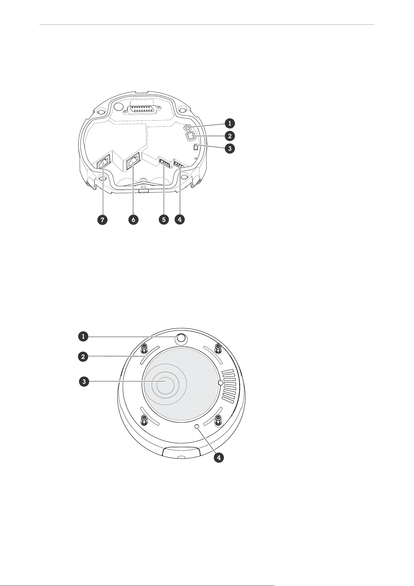
68
Specifications
Product overview
1 Status LED indicator
2 Control button
3 Microphone switch
4 I/O connector
5 RS-485 connector
6 Network connector (PoE OUT)
7 Network connector (PoE IN)
1 PIR sensor
2 Signaling LEDs
3 Speaker
4 Internal microphone
AXIS D6310 Air Quality Sensor

69
Status LED
Status LED Indication
Unlit Unlit for normal operation.
Green Steady for 10 seconds for normal operation after
startup completed.
Amber Steady during startup. Flashes during device software
upgrade or reset to factory default.
Amber/Red Flashes if network connection is unavailable or lost.
Buttons
Control button
The control button is used for:
• Resetting the product to factory default settings. See .
Microphone switch
For location of the microphone switch, see .
The microphone switch is used to mechanically turn the microphone ON or OFF. The factory default setting for
this switch is OFF.
Connectors
Network connector
Input: RJ45 Ethernet connector with Power over Ethernet (PoE).
Output: RJ45 Ethernet connector with Power over Ethernet (PoE).
I/O connector
Use the I/O connector with external devices in combination with, for example, motion detection, event
triggering, and alarm notifications. In addition to the 0 VDC reference point and power (12 V DC output), the I/O
connector provides the interface to:
Digital input - For connecting devices that can toggle between an open and closed circuit, for example PIR
sensors, door/window contacts, and glass break detectors.
Supervised input - Enables possibility to detect tampering on a digital input.
Digital output - For connecting external devices such as relays and LEDs. Connected devices can be activated by
the VAPIX® Application Programming Interface, through an event or from the device’s web interface.
4-pin terminal block
Function Pin Notes Specifications
DC ground 1 0 VDC
AXIS D6310 Air Quality Sensor
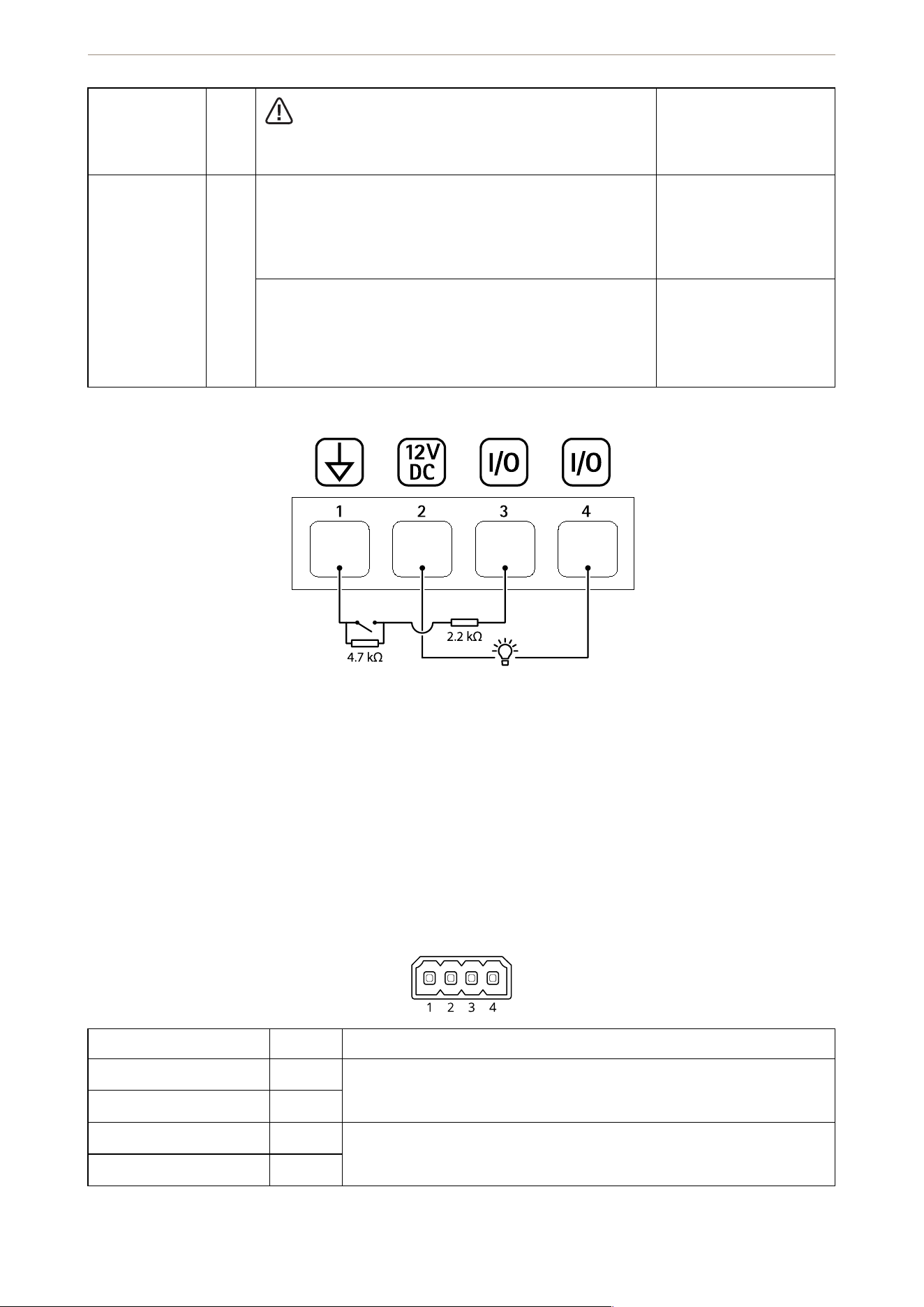
70
DC output 2
Can be used to power auxiliary equipment.
Note: This pin can only be used as power out.
12 VDC
Max load = 25 mA
Configurable
(Input or
Output)
3–4 Digital input or Supervised input – Connect to pin 1 to
activate, or leave floating (unconnected) to deactivate. To
use supervised input, install end-of-line resistors. See
connection diagram for information about how to
connect the resistors.
0 to max 30 VDC
Digital output – Internally connected to pin 1 (DC
ground) when active, and floating (unconnected) when
inactive. If used with an inductive load, e.g., a relay,
connect a diode in parallel with the load, to protect
against voltage transients.
0 to max 30 VDC, open
drain, 100 mA
Example:
1 DC ground
2 DC output 12 V, max 25 mA
3 I/O configured as supervised input
4 I/O configured as output
RS485/RS422 connector
Two 2-pin terminal blocks for RS485/RS422 serial interface. The serial port can be configured to support:
• Two-wire RS485 half duplex
• Four-wire RS485 full duplex
• Two-wire RS422 simplex
• Four-wire RS422 full duplex point to point communication
Function Pin Notes
RS485/RS422 RX/TX A 1 (RX) For full duplex RS485/RS422
(RX/TX) For half duplex RS485
RS485/RS422 RX/TX B 2
RS485/RS422 TX A 3 (TX) For full duplex RS485/RS422
RS485/RS422 TX B 4
AXIS D6310 Air Quality Sensor

71
Light pattern names
Off
Steady
Alternate
Pulse
Escalate 3 steps
Blink
Blink 3x
Blink 4x
Blink 3x fade
Blink 4x fade
Flash 1x
Flash 3x
Siren pattern names
Off
Alarm: Alarm high pitch
Alarm: Alarm low pitch
Alarm: Bird
Alarm: Boat horn
Alarm: Car alarm
Alarm: Car alarm fast
Alarm: Classic clock
Alarm: First attender
Alarm: Horror
Alarm: Industrial
Alarm: Single beep
Alarm: Soft quad beep
Alarm: Soft triple beep
Alarm: Triple high pitch
Notification: Accepted
Notification: Calling
Notification: Denied
Notification: Done
Notification: Entry
Notification: Failed
AXIS D6310 Air Quality Sensor

72
Notification: Hurry
Notification: Message
Notification: Next
Notification: Open
Siren: Alternate
Siren: Bouncy
Siren: Evac
Siren: Falling pitch
Siren: Home soft
AXIS D6310 Air Quality Sensor
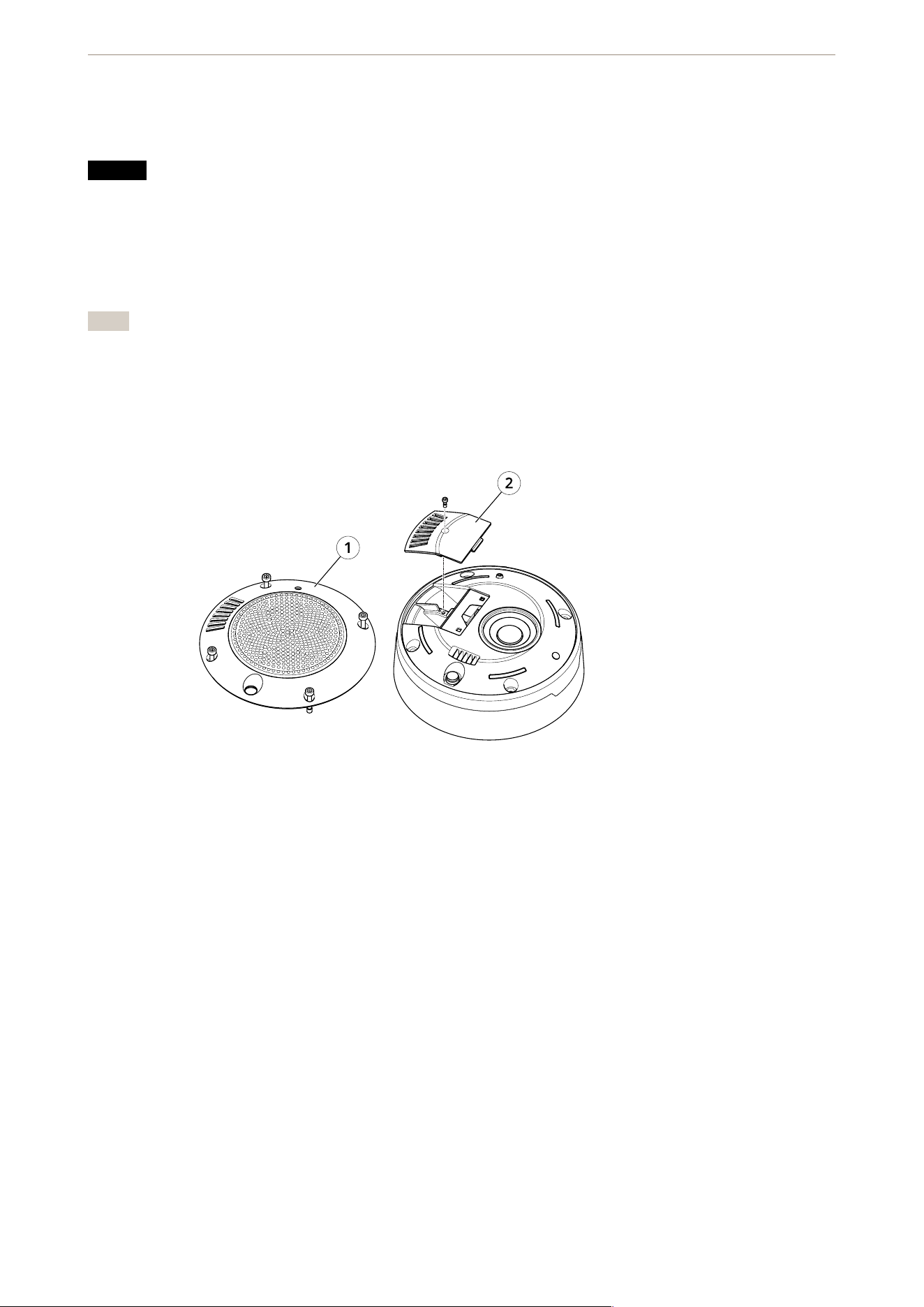
73
Clean your device
You can clean your device with lukewarm water.
NOTICE
• Harsh chemicals can damage the device. Don’t use chemicals such as window cleaner or acetone to
clean your device.
1. Use a can of compressed air to remove dust and loose dirt from the device.
2. If necessary, clean the device with a soft microfiber cloth dampened with lukewarm water.
3. To avoid stains, dry the device with a clean, nonabrasive cloth.
Note
• Remove the cover (1) and the door (2).
• Use a brush to clean the dust.
1 Cover
2 Door
AXIS D6310 Air Quality Sensor

74
Troubleshooting
Reset to factory default settings
Important
Reset to factory default should be used with caution. A reset to factory default resets all settings, including
the IP address, to the factory default values.
To reset the product to the factory default settings:
You can also reset parameters to factory default through the device’s web interface. Go to Maintenance >
Factory default and click Default.
Technical issues, clues, and solutions
If you can’t find what you’re looking for here, try the troubleshooting section at axis.com/support.
Problems upgrading AXIS OS
AXIS OS upgrade failure If the upgrade fails, the device reloads the previous version. The
most common reason is that the wrong AXIS OS file has been
uploaded. Check that the name of the AXIS OS file corresponds to
your device and try again.
Problems after AXIS OS upgrade If you experience problems after the upgrade, roll back to the
previously installed version from the Maintenance page.
Problems setting the IP address
The device is located on
a different subnet
If the IP address intended for the device and the IP address of the computer used to
access the device are located on different subnets, you cannot set the IP address.
Contact your network administrator to obtain an IP address.
The IP address is being
used by another device
Disconnect the Axis device from the network. Run the ping command (in a
Command/DOS window, type ping and the IP address of the device):
• If you receive: Reply from <IP address>: bytes=32; time=
10... this means that the IP address may already be in use by another
device on the network. Obtain a new IP address from the network
administrator and reinstall the device.
• If you receive: Request timed out, this means that the IP address is
available for use with the Axis device. Check all cabling and reinstall the
device.
Possible IP address
conflict with another
device on the same
subnet
The static IP address in the Axis device is used before the DHCP server sets a
dynamic address. This means that if the same default static IP address is also used
by another device, there may be problems accessing the device.
The device can’t be accessed from a browser
Can’t log in When HTTPS is enabled, ensure that the correct protocol (HTTP or HTTPS) is used
when attempting to log in. You may need to manually type http or https in the
browser’s address field.
If the password for the root account is lost, the device must be reset to the factory
default settings. See .
AXIS D6310 Air Quality Sensor

75
The IP address has been
changed by DHCP
IP addresses obtained from a DHCP server are dynamic and may change. If the IP
address has been changed, use AXIS IP Utility or AXIS Device Manager to locate the
device on the network. Identify the device using its model or serial number, or by
the DNS name (if the name has been configured).
If required, a static IP address can be assigned manually. For instructions, go to
axis.com/support.
Certificate error when
using IEEE 802.1X
For authentication to work properly, the date and time settings in the Axis device
must be synchronized with an NTP server. Go to System > Date and time.
The device is accessible locally but not externally
To access the device externally, we recommend you to use one of the following applications for Windows
®
:
• AXIS Camera Station Edge: free of charge, ideal for small systems with basic surveillance needs.
• AXIS Camera Station 5: 30-day trial version free of charge, ideal for small to mid-size systems.
• AXIS Camera Station Pro: 90-day trial version free of charge, ideal for small to mid-size systems.
For instructions and download, go to axis.com/vms.
Can’t connect over port 8883 with MQTT over SSL
The firewall blocks
traffic using port 8883
as it’s deemed insecure.
In some cases the server/broker might not provide a specific port for MQTT
communication. It may still be possible to use MQTT over a port normally used for
HTTP/HTTPS traffic.
• If the server/broker supports WebSocket/WebSocket Secure (WS/WSS),
typically on port 443, use this protocol instead. Check with the
server/broker provider to see if WS/WSS is supported and which port and
basepath to use.
• If the server/broker supports ALPN, the use of MQTT can be negotiated over
an open port, such as 443. Check with your server/broker provider to see if
ALPN is supported and which ALPN protocol and port to use.
The device doesn’t start up after connecting it to another product
Wrong PoE class Check that a PoE class 4 power supply is used, when the device is connected to
another product.
The sensor data is not accurate
The sensor data
inaccurate
The AQI (Air Quality Index), CO2, VOC and NOx take time to be functional. See .
Performance considerations
The following factors are the most important to consider:
• Heavy network utilization due to poor infrastructure affects the bandwidth.
Contact support
If you need more help, go to axis.com/support.
AXIS D6310 Air Quality Sensor

.
T10222990
2025-02 (M1.49)
© 2025 Axis Communications AB