
Operating and Installation Instructions
Ventilation Hood
To prevent accidents and damage to the appliance, you must r
ead
these instructions before installing the appliance and using it for the first
time.
en-US M.-Nr. 09 968 240
Contents
2
IMPORTANT SAFETY INSTRUCTIONS................................................................. 3
Caring for the environment................................................................................. 12
Description of functions...................................................................................... 13
Guide to the appliance......................................................................................... 14
Operation .............................................................................................................. 16
Turning on the fan .................................................................................................. 16
Selecting the power level....................................................................................... 16
Turning off the fan.................................................................................................. 17
Turning cooktop lighting On/Off............................................................................. 17
Automatic safety shut-down.................................................................................. 17
Cleaning and care................................................................................................ 18
Stainless steel housing .......................................................................................... 18
Grease filters.......................................................................................................... 19
OdorFree Charcoal Filter........................................................................................ 21
Disposing of the OdorFree Charcoal Filter........................................................ 21
Changing an overhead light................................................................................... 22
Installation ............................................................................................................ 23
Before installation .................................................................................................. 23
Removing the protective film ................................................................................. 23
Installation Instructions.......................................................................................... 23
Disassembly........................................................................................................... 23
Installation parts..................................................................................................... 24
Appliance dimensions............................................................................................ 26
Distance between cooktop and ventilation hood (S) ............................................. 27
Installation recommendations................................................................................ 29
Drilling diagram for wall mounting ......................................................................... 29
Plywood backing .................................................................................................. 30
To install a plywood backing ................................................................................. 30
Exhaust duct.........................................................................................................
31
Condensate trap .................................................................................................... 32
Reducing Collar .................................................................................................... 32
Electrical connection........................................................................................... 33
Service and warranty........................................................................................... 34
Location of the data plate ...................................................................................... 34
Technical data ..................................................................................................... 35
IMPORTANT SAFETY INSTRUCTIONS
3
READ AND SAVE THESE INSTRUCTIONS
This appliance complies with current safety requirements.
Improper use of the appliance can
lead to personal injury and
material damage.
Read all instructions before installing or using the appliance for
the first time. Only use the appliance for its intended purpose.
Keep these operating instructions in a safe place and pass them
on to any future user.
Use
CAUTION: For General Ventilating Use Only. Do Not Use To
Exhaust Hazar
dous Or Explosive Materials And Vapors.
This appliance is int
ended for residential use only. Use only as
described in these operating instructions.
This ventilation ho
od is not intended for outdoor use.
It must only be used to extract and clean vapors produced during
cooking. Any other use occurs at the owner's own risk.
This appliance is suitable for installation above gas or electric
cooking sur
faces.
Persons who lack physical, sensory or mental abilities, or
e
xperience with the appliance should not use it without supervision
or instruction by a responsible person.
IMPORTANT SAFETY INSTRUCTIONS
4
Children
As with any appliance, close supervision is necessary when used
by childr
en.
Please supervise ch
ildren in the vicinity of the hood and do not let
them play with it.
Danger of suffocation! Ensure that any plastic wrappings, bags,
etc. ar
e disposed of safely and kept out of the reach of children.
Technical safety
WARNING: TO REDUCE THE RISK OF FIRE, ELECTRIC SHOCK,
OR I
NJURY TO PERSONS, OBSERVE THE FOLLOWING:
– Use this appliance only in the manner intended by the
manufactur
er. If you have questions, contact Miele.
– Before servicing or cleaning the appliance, switch power off at
the servi
ce panel and lock the service disconnecting means to
prevent power from being switched on accidentally. If the service
disconnecting means cannot be locked, securely fasten a
prominent warning device, such as a tag, to the service panel.
Installatio
n,
repair and maintenance work should be performed by
a Miele authorized service technician in accordance with national
and local safety regulations and the provided installation
instructions. Contact Miele’s Technical Service Department for
examination, repair or adjustment. Repairs and other work by
unauthorized persons could be dangerous and may void the
warranty.
A damaged ventilation hood oven can be dangerous. Always
check for visible signs of damage. Never use a damaged ventilation
hood.
IMPORTANT SAFETY INSTRUCTIONS
5
Be certain your appliance is properly installed and grounded by a
qualifie
d technician. To guarantee the electrical safety of this
appliance, continuity must exist between the appliance and an
effective grounding system. It is imperative that this basic safety
requirement be met. If there is any doubt, have the electrical system
of the house checked by a qualified electrician.
To avoid damaging the ventilation hood, make sure that the
conn
ection data (voltage and frequency) on the data plate
correspond to the building's power supply before connecting the
appliance. When in doubt, consult a qualified electrician.
Do not use a power bar or e
xt
ension cord to connect the
ventilation hood to electricity. These are a fire hazard and do not
guarantee the required level of appliance safety.
To ensure safe operation, only use the ventilation hood after it has
been pr
operly installed.
This ventilation hood may not be used in non-stationary locations
(e.g. on a ship).
Only open the housing as described in the enclosed "Installation
diagr
am" and in the "Clean
ing and care" section of this manual.
Under no circumstances should any other parts of the housing be
opened.
Tampering with electrical connections or components and
mechanical parts is highly dangerous to the user and can cause
operation faults.

IMPORTANT SAFETY INSTRUCTIONS
6
Defective comp
onents should be replaced by Miele original parts
only. Only with these parts can the manufacturer guarantee the
safety of the appliance.
If the power cord is damaged, it must only be replaced by a
qualifie
d service technician.
During installation, maintenance, and repair work, the ventilation
hoo
d must be disconnected from the electrical supply. It is only
completely isolated from the electricity supply if one of the following
applies:
– The circuit breakers on the electrical service panel are tripped.
– The screw-type fuses on the electrical service panel have been
remo
ved.
– The power cable (if present) has been unplugged from the socket
(pull the plug not
the cord).
Proper use
WARNING: TO REDUCE THE RISK OF A COOKTOP GREASE
FIRE:
– a) Never leave surface units unattended at high settings.
Boilovers cause smo
king and greasy spillovers may ignite. Heat
oils slowly on low or medium settings.
– b) Always turn the hood on when cooking at a high heat.
– c) Clean the ventilation hood frequently. Grease should not be
allowed
to accumulate on the fan or filter.
– d) Use the proper pan size. Always use cookware appropriate for
the size
of the cooking area.
Never use an open flame beneath the ventilation hood.
To avo
id the risk of fire, do not flambé or grill over an open flame.
When turned on, the ventilation hood will draw any flames into the
filter. Fat deposits may ignite.
IMPORTANT SAFETY INSTRUCTIONS
7
WARNING: TO REDUCE THE RISK OF INJURY TO PERSONS IN
THE EVENT OF A
COOKTOP GREASE FIRE, OBSERVE THE
FOLLOWING*:
– a) SMOTHER FLAMES with a close fitting lid, cookie sheet, or
metal
tray then turn off the burner. BE CAREFUL TO PREVENT
BURNS. If the flames do not go out immediately, EVACUATE AND
CALL THE FIRE DEPARTMENT.
– b) NEVER PICK UP A FLAMING PAN - You may be burned.
– c) DO NOT USE WATER, including wet dishcloths or towels - a
violent steam explosion will result.
– d) Use a fire extinguisher ONLY if:
– 1) You have a class ABC extinguisher, and you know how to operate it.
– 2) The fire is small and contained in the area where it started.
– 3) The fire department is being called.
– 4) You can fight the fire with your back to an exit.
*Based on "Kitchen Firesafety Tips" published by NFPA.
The ventilation ho
od may become damaged if exposed to
excessive heat from a gas cooktop.
– When using the ventilation hood over a gas cooktop, ensure that
any burners
in use are always covered by cookware. Turn burners
off when removing the cookware, even if doing so for just a short
time.
– Select cookware that is suitable for the size of the burner.
– Adjust the flame so that it never extends up the sides of the
cookwar
e.
– Avoid overheating the cookware (e.g., when cooking with a wok).
Always turn the ventila
t
ion hood on whenever a burner is in use to
prevent damage from condensation.
IMPORTANT SAFETY INSTRUCTIONS
8
Overheated oils and fats can ign
ite and set the ventilation hood
on fire.
When cooking with oils or fats, do not leave pots, pans or fryers
unattended. Never leave an electric grill unattended when grilling.
Fat and debris deposits impair the proper functioning of the
ventilation hood.
T
o ensure that cooking vapors are properly cleaned, never use the
ventilation hood without the grease filters in place.
A filter containing too much grease is a fire hazard!
The fil
ters should be cleaned or replaced at regular intervals.
Please not
e that the heat rising from the stovetop during cooking
can cause the ventilation hood to become very hot.
Do not touch the housing or the grease filters until the ventilation
hood has cooled down.
IMPORTANT SAFETY INSTRUCTIONS
9
Proper installation
WARNING: TO REDUCE THE RISK OF FIRE, ELECTRIC SHOCK,
OR I
NJURY TO PERSONS, OBSERVE THE FOLLOWING:
– a) Installation work and electrical wiring must be done by
qualif
ied person(s) in accordance with all applicable codes and
standards, including fire-rated construction.
– b) Sufficient air is needed for combustion and exhausting of
ga
ses
through the flue (chimney of fuel burning equipment to
prevent back drafting. Follow the heating equipment
manufacturer’s guideline and safety standards such as those
published by the National Fire Protection Association (NFPA) and
the American Society for Heating, Refrigeration and Air
Conditioning Engineers (ASHRAE), and the local code authorities.
– c) When cutting or drilling into the wall or ceiling, do not damage
electrical wiring and other hidden utilities.
– d) Ducted hoods must always be vented to the outdoors.
– e) Do not use this hood with any solid-state speed control device.
To determine whether a ventilation hood may be operated above
your co
oking appliance, please refer to the information provided by
the appliance's manufacturer.
Safety regulations prohibit the installation of a ventilation hood
above soli
d fuel stoves.
Insufficient distance between the cooking appliance and the
ventilation hoo
d can result in damage to the hood.
The minimum safety distances between the appliance and the
bottom of the ventilation hood specified in the "Installation" section
must be maintained, unless the appliance's manufacturer has
indicated that a greater distance is required.
If more than one cooking appliance is used beneath the ventilation
hood, and if different minimum safety distances apply for these
appliances, you should use the greater distance.

IMPORTANT SAFETY INSTRUCTIONS
10
Be sure to observe the information contained in the "Installation"
section when mounting the ventilation hood.
When installing the e
xhaust duct, only use pipes or tubes made of
non-flammable material. These can be obtained from your Miele
dealer or from Miele Technical Service.
Exhaust air should
not be vented into a chimney or vent flue
which is otherwise in use and should not be channeled into ducting
which ventilates rooms with fuel-burning installations.
If exhaust air is to be extracted into a chimney or vent flue no
lon
ger used for other purposes, be sure to comply with all applicable
regulations.
WARNING: TO REDUCE THE RISK OF FIRE USE ONLY METAL
DUC
TWORK.

IMPORTANT SAFETY INSTRUCTIONS
11
Cleaning and care
Never use a steam cle
aner to clean the ventilation hood.
The steam can reach the electrical components and cause a short
circuit.
Accessories
Use only genuine ori
ginal Miele parts. If parts or accessories from
other manufacturers are used, the warranty will become void.

Caring for the environment
12
Disposal of the packing
material
The cardboard box and packing
mater
ials protect the appliance during
shipping. They have been designed to
be biodegradable and recyclable.
Ensure that any plastic wrappings,
bags,
etc. are disposed of safely and
kept out of the reach of children.
Danger of suffocation!
Disposal of your old appliance
Do not dispose of this appliance with
your household wast
e.
Old appliances may contain materials
that can be recycle
d. Please contact
your local recycling authority about the
possibility of recycling these materials.
Before discarding an old appliance
ensure
that it presents no danger to
children while being stored for disposal.
Unplug it from the outlet, cut off its
power cord and remove any doors to
prevent hazards.
Description of functions
13
The following functions are available on
your ventilation hood, depending on the
model:
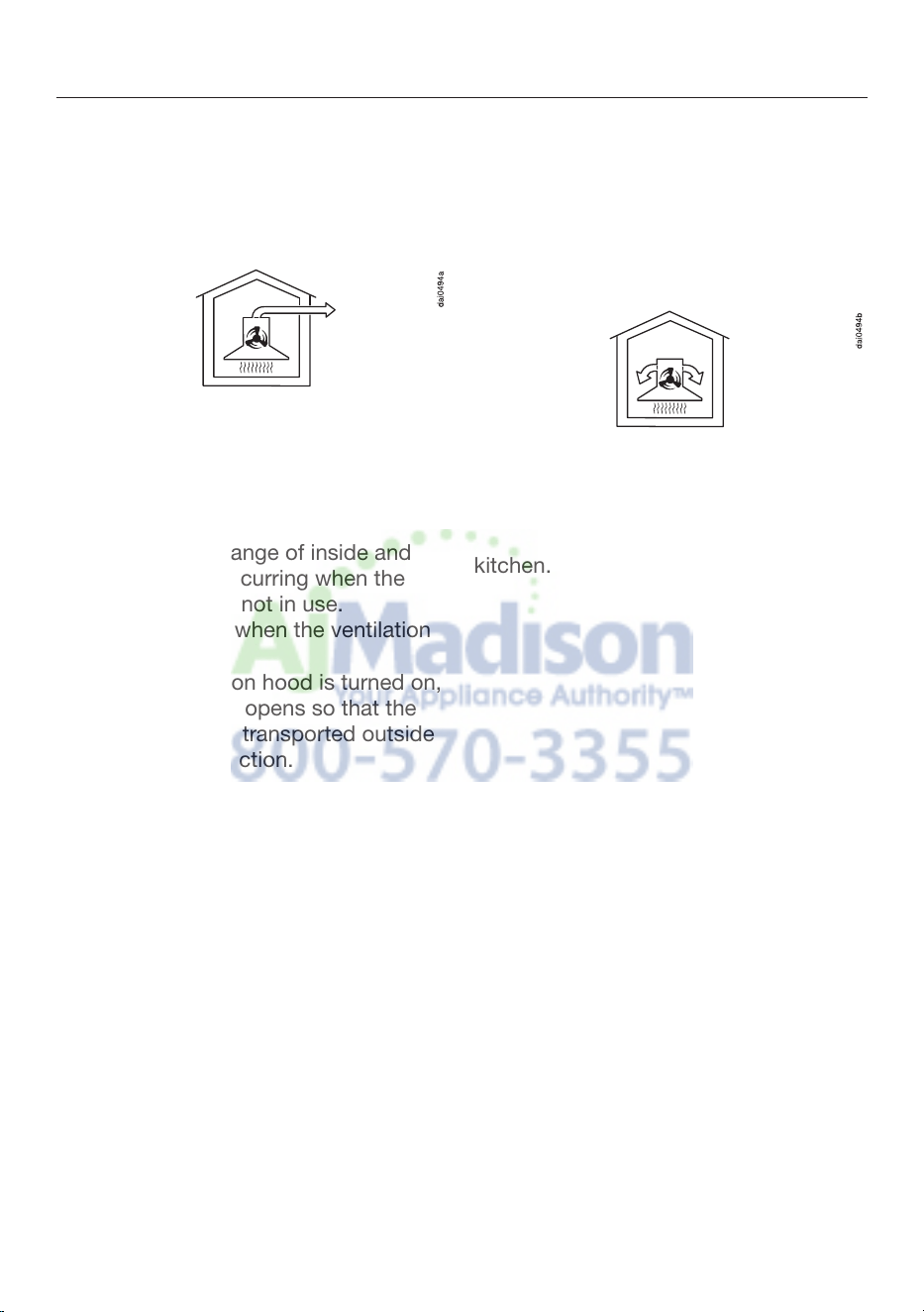
Vented mode
The air is drawn in and cleaned by the
grease
filters and directed outside.
Non-return flap
A non-return flap in the ducting
prevents the e
xchange of inside and
outside air from occurring when the
ventilation hood is not in use.
The flap is closed when the ventilation
hood is turned off.
When the ventilation hood is turned on,
the non-return flap opens so that the
exhaust air can be transported outside
without any obstruction.
A non-return flap has been provided
with the hood in case your ducting
does not have o
ne.
It is inserted into
the outlet duct collar of the fan.
Recirculation mode
The recirculation mode requires a
recir
culation kit and OdorFree Charcoal
Filter (available as optional accessories,
see "Technical Data" for more
information)
The air is drawn in and first cleaned by
the grease
filters and then by an
OdorFree Charcoal Filter. The cleaned
air is then recirculated back into the
kitchen.
Guide to the appliance
14

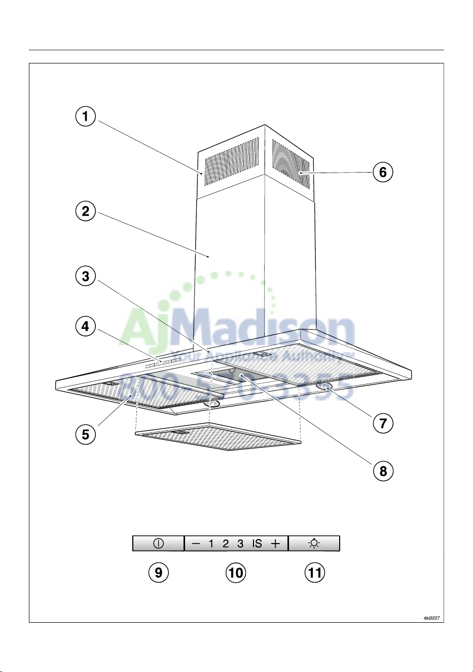
Guide to the appliance
15
a
Telescopic chimney
b
Chimney
c
Canopy
d
Control panel
e
Grease filter
f
Recirculation vent
(only for recirculation mode)
g
Cooktop lighting
h
OdorFree Charcoal Filter
Optional accessory for recirculation mode
i
On/Off button for fan
j
Buttons for setting the fan power
k
On/Off touch control for the cooktop lighting

Operation
16
Turning on the fan
Press the On/Off button
.
The fan turns on at level 2. The
symbol and 2 will light up in the fan
level
display.
Selecting the power level
Power levels 1 to
3 can be used for light
to heavy cooking vapors and odors.
For strong vapors and odors that are
temporarily produced when cooking,
e.g. during searing, select the IS level
as an intensive setting.
P
ress the "" button for a lower
power level or the "
" button to
select a higher level.
Automatically switching back
from th
e intensive level (IS)
The intensive level can be programmed
to switch back t
o level 3 automatically
after 10 minutes.
To do so, turn off the fan and the
coo
ktop lighting.
P
ress the and buttons at the
same time for appr
ox. 10 seconds,
until 1 lights up.
Then, press the following buttons in
or
der:
– The lighting button ,
– Followed by the button and then
– The lighting button again.
If automatic switch-off is not activated,
the 1 and IS displays will flash.
To activate it, press the button.
If 1 and IS are li
t up, automatic switch-
off is activated.
To deactivate it, press the button.
Use the On/Off control
to confirm
your choice of setting.
If you do not confirm within 4
minutes, the hood will revert to the
old setting.

Operation
17
Turning off the fan
Press the On/Off button
to turn the
fan off.
The symbol will go out.
Turning cooktop lighting
On/Off
The cooktop lighting can be turned on
a
nd off separ
ately from the fan.
To do so, press the button.
The symbol is lit when the cooktop
lighting is turned on.
Automatic safety shut-down
Should the hood be left on, the fan will
switch off automati
cally after 10 hours.
The lighting will remain on.
P
ressing the On/Off button will
switch the fan back on again.
Cleaning and care
18
WARNING: TO REDUCE THE RISK
OF FIRE, ELECTRIC SHOCK, OR
INJURY TO PERSONS, OBSERVE
THE FOLLOWING:
Before cleaning or servicing the
hoo
d, disconnect it from the power
supply, see "IMPORTANT SAFETY
INSTRUCTIONS".
Stainless steel housing
General
The surfaces and control buttons are
susce
p
tible to scratching and
chipping.
Observe the following cleaning
instructions.
Clean all surfaces and control
butt
ons using warm water and liquid
dish soap only, applying the mixture
with a sponge cloth.
Make sure that no water gets into
the int
erior of the hood.
Only use a damp cloth to clean the
hood,
especially in the control panel
area.
After cleaning, dry the surfaces with a
soft cloth.
Avoid the following:
– Cleaners containing soda, acid or
chloride, or cleaners containing
solvents
– Abrasive cleaners such as scouring
powder, scouring liquid, abrasive
sponges such as pot scourers, or
used sponges that still contain
residues from abrasive cleaners
Special instructions for stainless
steel sur
faces
(does not apply to control buttons)
Stainless steel surfaces can also be
clea
ned using a non-abrasive
stainless steel cleaner, available from
Miele.
T
o prevent the surfaces from quickly
becomi
ng dirty again, we
recommend treating them with a
stainless steel care conditioner.
Apply sparingly over the entire area
using a soft cloth.
Special instructions for RAL color
finish housing
(special order)
Observe the general cleaning
in
structions contained in this chapter.
Minor scratches on the surface are
inevitable when cleaning the housing.
Depending on the lighting in the
kitchen, this may negatively affect the
app
liance's appearance.
Cleaning and care
19
Special instructions for control
button
s
Do not leave dirt and debris on the
buttons for any le
ngth of time.
Otherwise they may become
discolor
ed or damaged.
Remove any dirt or debris
immediately.
Observe the general cleaning
instructions contained in this chapter.
Do not use a stainless steel cleaner
to cle
an the control buttons.
Grease filters
The reusable metal grease filters in the
appliance remo
ve the solid particles
contained in kitchen vapors (fat, dust,
etc.), thereby preventing the ventilation
hood from becoming dirty.
A dirty filter is a fire hazard!
Cleaning intervals
Over longer periods of time, fat buildup
on the gre
ase filter hardens and makes
cleaning more difficult. Therefore, we
recommend cleaning the grease filters
once every 3-4 weeks.
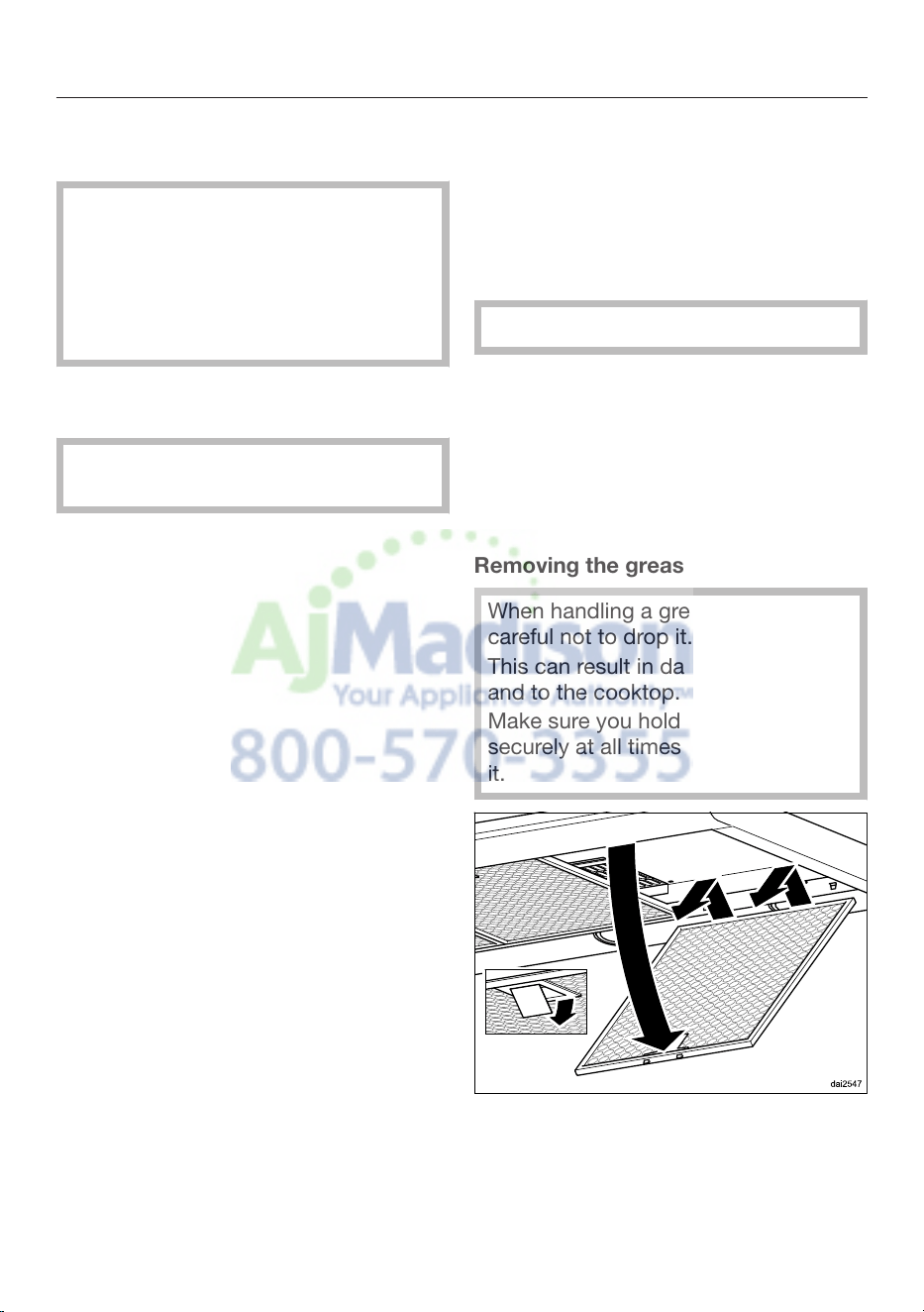
Removing the grease filters
When handling a grease filter, be
care
ful not to drop it.
This can result in damage to the filter
and to the coo
ktop.
Make sure you hold the filter
secur
ely at all times when handling
it.
T
o remove a grease filter, release the
lo
cking clip. Then, open the filter to a
45° angle, unhook it, and remove it
from the hood.
Cleaning and care
20
Cleaning the grease filters by hand
Clean the filters with a soft nylon
brush in a mil
d solution of hot water
and dish soap. Do not use undiluted
dish soap.
Unsuitable cleaning agents
Unsuitable cleaners can cause damage
to the filter surfaces if used regularly.
Do not use any of the following:
– Lime removers
– Abrasive powders or abrasive liquids
– Aggressive all-purpose cleaners and
degrease
r sprays
– Oven sprays
Cleaning the grease filters in the
dishwasher
Place
the filters as upright or inclined
as possible in
the lower basket.
Ensure that the spray arm is not
obstructed.
Use a common household
dishwasher deter
gent.
Select a program with a wash
t
emperature between 122°F (50°C)
and 149°F (65°C). In a Miele
dishwasher use the "Normal"
program.
Depending on the detergent used,
cleaning the filt
ers in a dishwasher
may cause the inside filter surfaces to
become discolored. However, this will
not affect the functioning of the filters
in any way.
After cleaning
After cleaning, leave the filters on an
absorbent sur
face to dry.
When removing the filters for
cleaning, also clean off any
acce
ssible oil or fat buildup from the
housing. Doing so will prevent a fire
hazard.
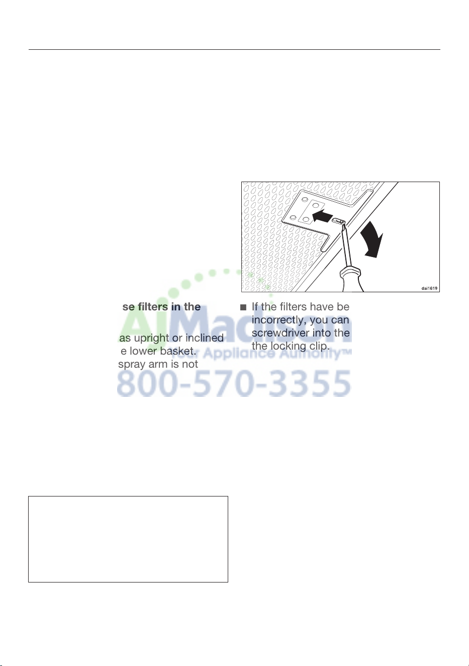
Reinstall the grease filters. When
inse
rting the filters, make sure that
the locking clip is facing down.
If the filters have been installed
inc
orrectly, you can insert a small
screwdriver into the slit to disengage
the locking clip.
Cleaning and care
21
OdorFree Charcoal Filter
If the hood is equipped for recirculation,
an OdorFr
ee Charcoal Filter must be
installed in addition to the grease filters.
This filter is designed to absorb odor-
causing agents and is mounted in the
canopy above the grease filters.
OdorFree Charcoal Filters are available
from your Miele dealer or from Miele.
See "Technical data" for the type and
reference number.
Installing/replacing the OdorFree
Charc
oal Filter
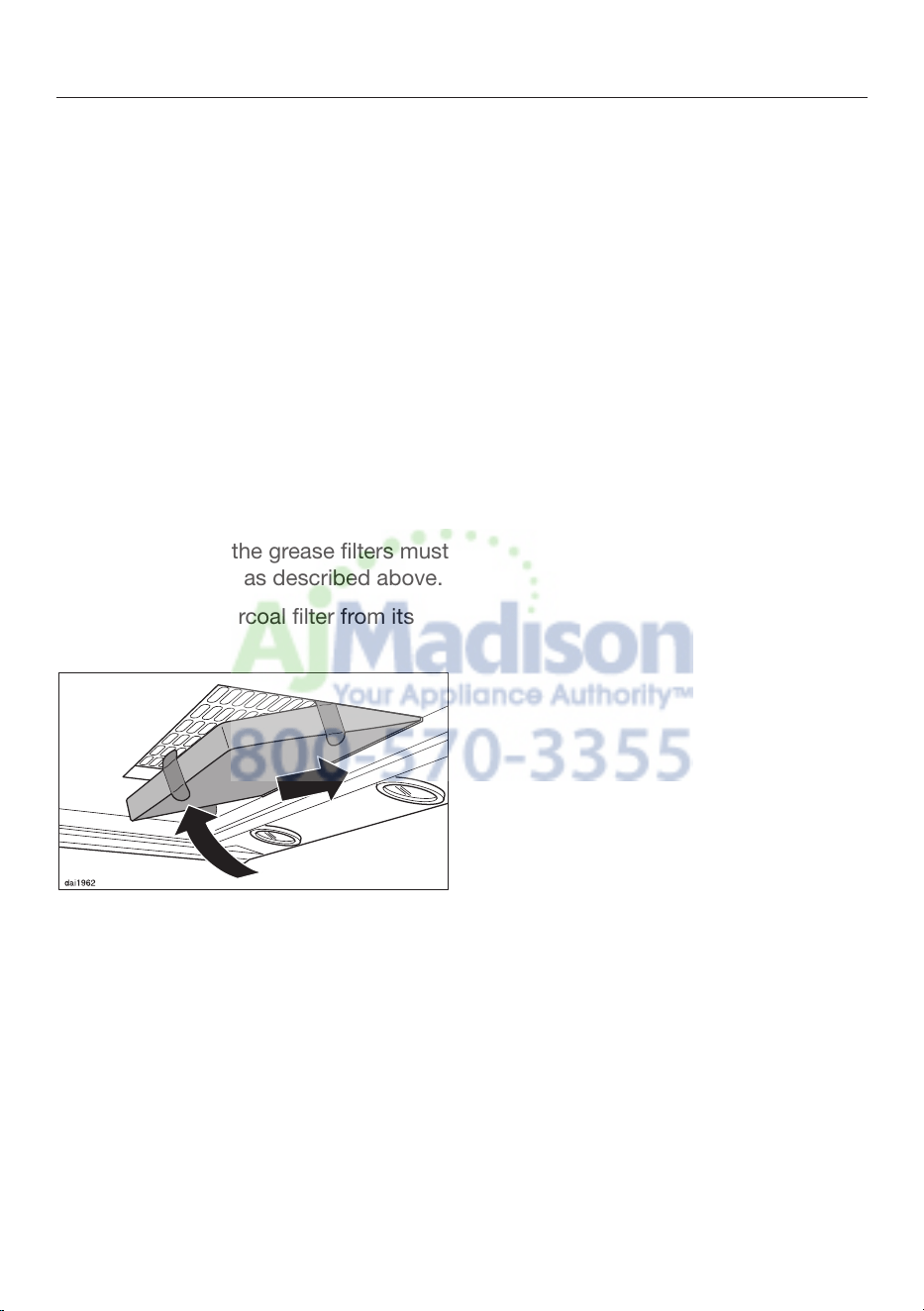
To install or replace the OdorFree
Cha
rcoal Filter, the grease filters must
first be removed as described above.
Remove the charcoal filter from its
packaging.
Slide the OdorFr
ee Charcoal Filter
into the back of the intake frame,
then push the front of the filter up into
the frame.
Reinstall the grease filters.
When to change the OdorFree
Charc
oal Filter
Always replace the OdorFree
Cha
rcoal Filter whenever it no longer
absorbs kitchen odors effectively.
Replace the filter at least once every
6 months.
Disposing of the OdorFree Charcoal
Filt
er
Used OdorFr
ee Charcoal Filters can
be disposed of with normal
household waste.
Cleaning and care
22
Changing an overhead light
The halogen lights become very hot
when in use.
They can cause burns even after
being shut off for some time.
Allow them to cool down for a few
minut
es before changing them.
Disconnect the hood from the
ele
ctrical supply before replacing the
lamps (see "IMPOARTANT SAFETY
INSTRUCTIONS").
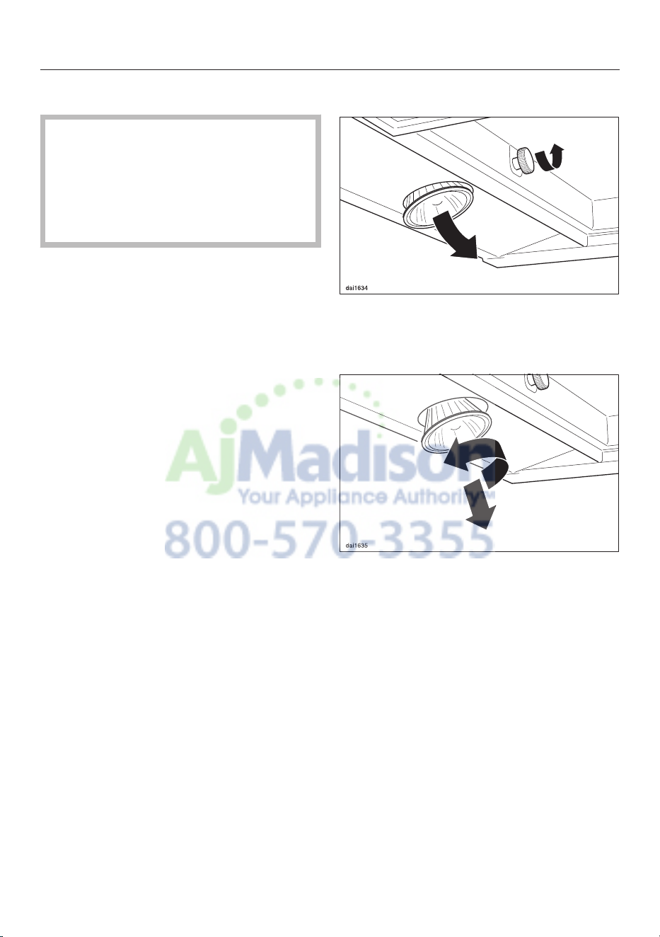
Remove the grease filters.
Turn the bolt counterclockwise as far
as it will go. The halogen lamp will
then dr
op down towards you.
Turn the light counter clockwise and
pull it out.
Replace it with a new lamp of the
same type: G
U
/GZ 10, 120 V, 50W.
Refit the lamp by reversing the steps
shown above. Please observe
manufacturer's instructions.
Replace the grease filter.
Installation
23
Before installation
Before installing the appliance,
r
ead all of the information contained
in this chapter and also in the
"IMPORTANT SAFETY
INSTRUCTIONS" section.
Removing the protective film
The housing components are covered
by a pr
otective film to prevent them
from becoming damaged during
transport.
Please remove this film before
installing the housing components. It
can be peeled off easily without any
additiona
l tools.
Installation Instructions
Please refer to the accompanying
installation sheet for instructions on
how t
o install
the appliance.
Disassembly
If the device ever needs to be
disassembled, follow the installation
shee
t
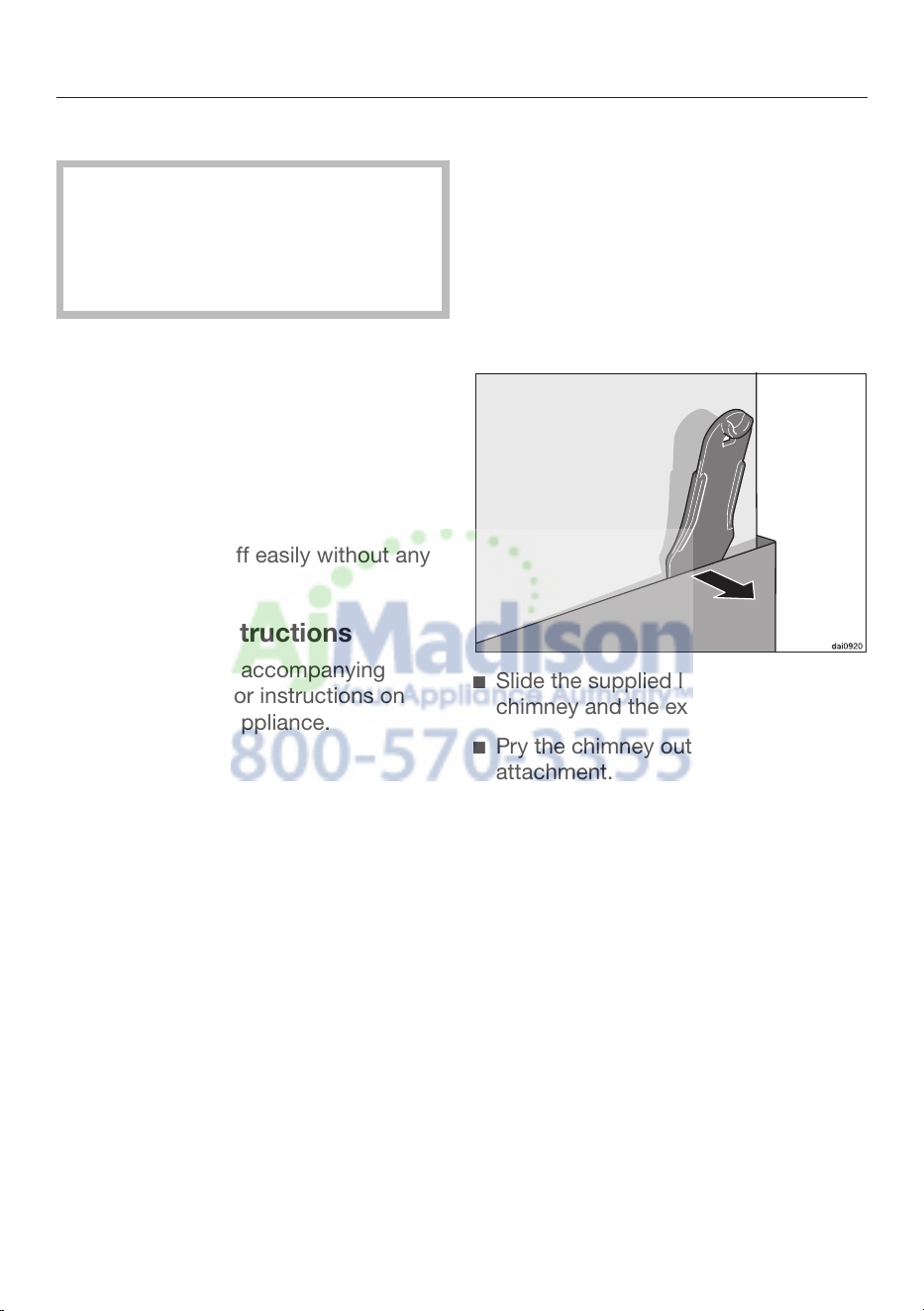
instructions in reverse order. A
lever is provided to assist with the
removal of the chimney.
Unscrew the two mounting screws on
the chi
mney.
Slide the supplied lever between the
chimney and t
he extension piece.
P
ry the chimney out of its
attachment.
Installation
24
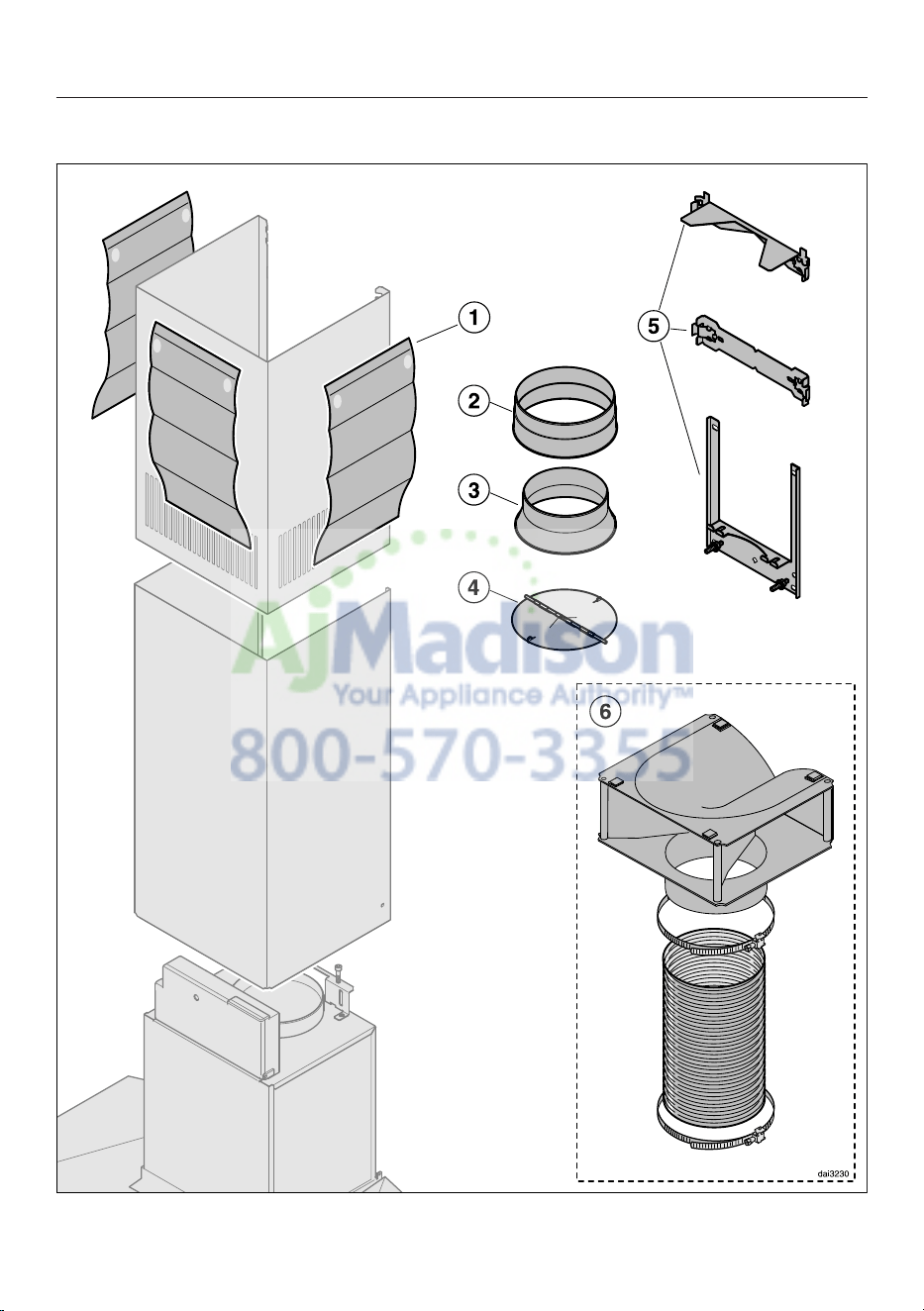
Installation parts
Installation
25
a
3 protective installation sheets
for use when installing the chimney
b
1 exhaust connector
for an exhaust duct 6" (150 mm).
c
1 reducer
for an exhaust duct 5" (125 mm).
d
1 non-return flap
for installation in the outlet duct
collar of the motor unit (not for
recirculation mode). Depending on
the device version, the non-return
flap is already mounted.
e
Wall bracket
for securing the hood on the wall.
f
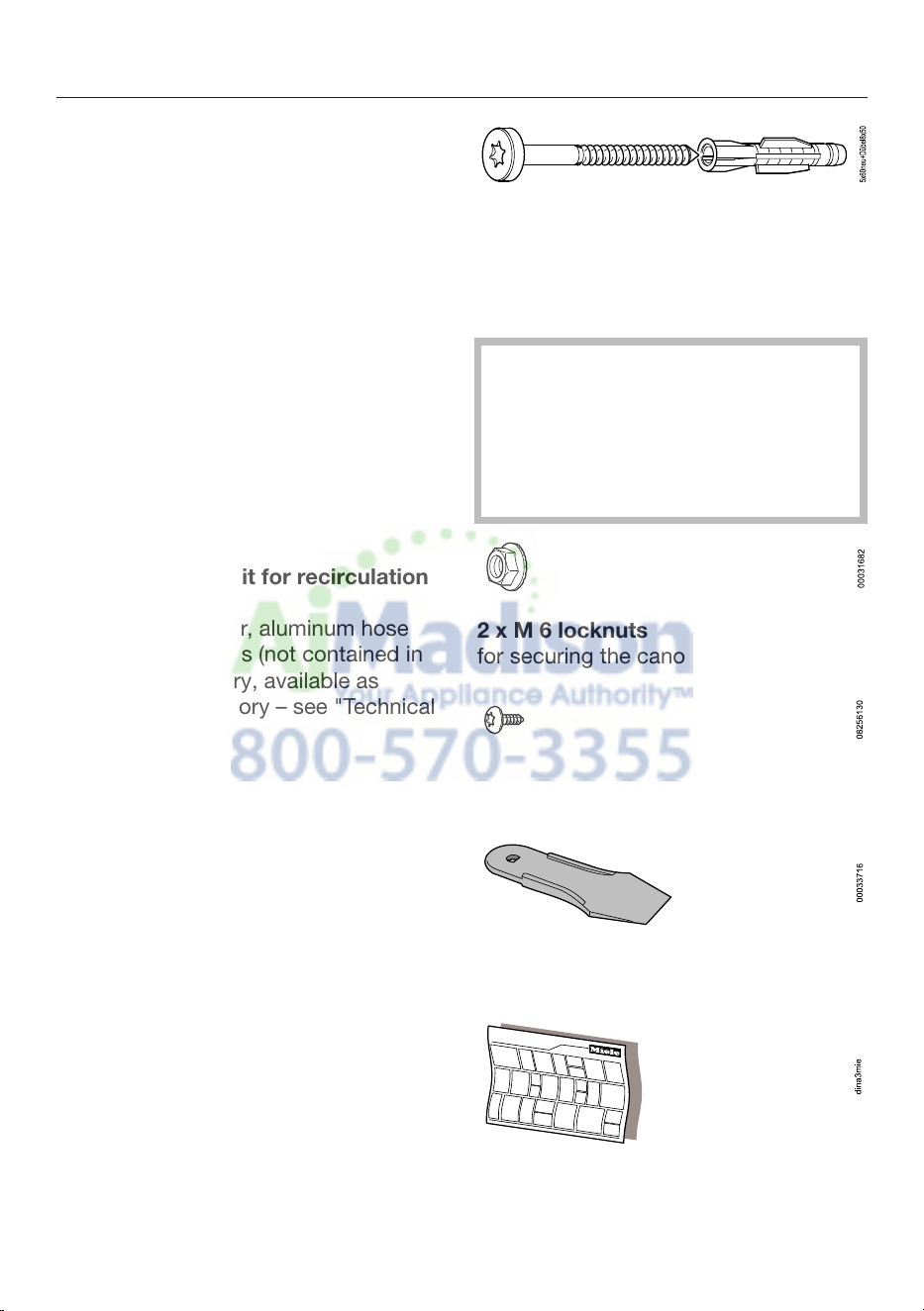
Recirculation kit for recirculation
mode
contains diverter, aluminum hose
and hose clamps (not contained in
scope of deliver
y, avail
able as
optional accessory – see "Technical
Data").
8 screws, 3/16" x 2 3/8" (5 x 60 mm)
8 plugs, 5/16" x 2" (8 x 50 mm)
for attaching to the wall (not for use in
USA / CDN).
The screws and plugs are designed
for use in
solid walls only.
Use different fasteners for other wall
construction types.
Make sure that the wall can support
the load.
2 x M 6 locknuts
for securing the canopy.
2 screws 1/8" x 5/16" (3.9 x 7.5 mm)
for attaching the chimney.
1 lever
for disassembling the chimney.
Montage
Installation
Montaje
Montaggio
Montering
Montagem
Asennus
Installation sheet
Installation
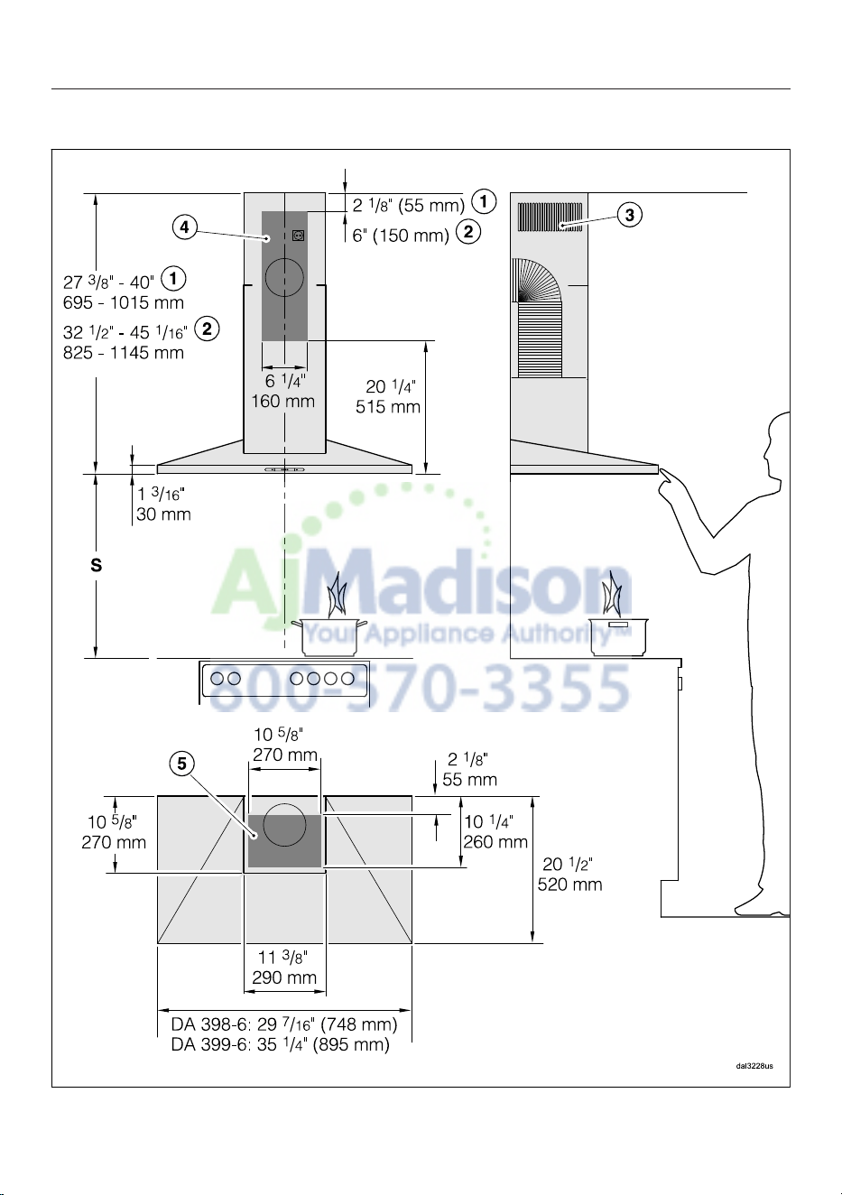
26
Appliance dimensions
The drawing is not to scale.
Installation
27
a
Extraction
b
Recirculation
c
Air vent positioned at top for recirculation
de
Mounting area (only d is requir
ed for recirculation ventilation hoods). Wall
and ceiling area for exhaust duct opening and for wall socket installation.
Only the wall socket installation is required for recirculation hoods.
Vent collar
6
" (150 mm), with adapter 5" (125 mm).
Distance between cooktop and ventilation hood (S)
Provided a larger distance is not given by the manufacturer of the cooktop,
follow t
he minimum safety distances between a cooktop and the bottom of the
hood.
Please also observe the information contained in the "IMPORTANT SAFETY
INSTRU
CTIONS" section.
Installation
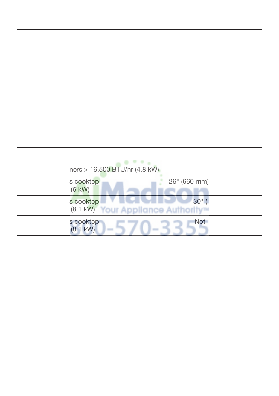
28
Minimum distance S
Cooking appliance Miele
appliance
Non-Miele
appliance
Electric/Induction cooktop 24" (610 mm)
Electric grill, deep fat fryer (electric) 26" (660 mm)
Multi-burner gas cooktop
≤ 43,000 BTU
/hr (12.6 W),
no burner > 15,000 BTU/hr (4.5 kW).
26" (660 mm) 30" (760 mm)
Multi-burner gas cooktop
≤ 73,800 BTU
/hr (21.6 W),
no burner > 16,500 BTU/hr (4.8 kW)
30" (760 mm)
Multi-burner gas cooktop
> 73,800 BTU
/hr (21.6 W),
or one of the burners > 16,500 BTU/hr (4.8 kW)
Not possible
Single-burner gas cooktop
≤ 20,500 BTU
/hr (6 kW)
26" (660 mm) 30" (760 mm)
Single-burner gas cooktop
≤ 27,600 BTU
/hr (8.1 kW)
30" (760 mm)
Single-burner gas cooktop
> 27,600 B
TU
/hr (8.1 kW)
Not possible
Installation
29
Installation recommendations
– We also recommend a distance of at
least 25 1/2" (650 mm) above electric
coo
kt
ops to provide more workspace
and easier cooking under the hood.
– When selecting an installation height,
always take the use
r height into
consideration. Users should have
ample space to work comfortably on
the cooktop and reach the ventilation
hood controls with ease.
– Please note that the greater the
distance
from the cooktop, the less
effective the hood is at drawing in the
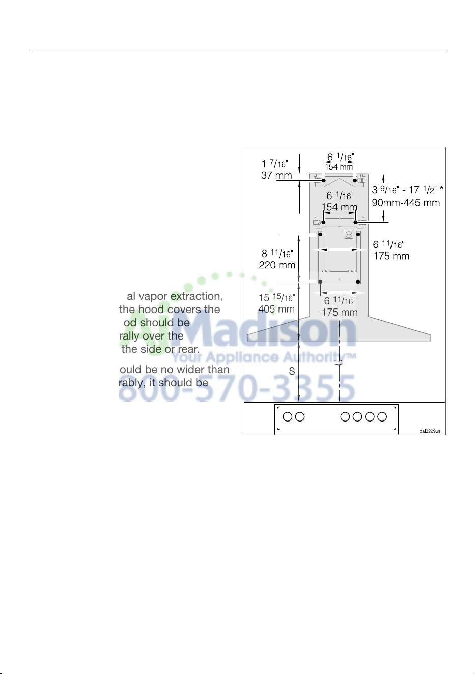
cooking vapors.
– To achieve optimal vapor extraction,
make sur
e that the hood covers the
cooktop. The hood should be
positioned centrally over the
cooktop, not to the side or rear.
– The cooktop should be no wider than
the hood.
Preferably, it should be
narrower.
– The mounting area must be easily
accessible. The ventilation hood
sho
uld
be easy to reach and
disassemble in case a service call is
necessary. This should be taken into
consideration when planning the
position of cupboards, shelves,
ceilings or decorative elements in the
vicinity of the ventilation hood.
Drilling diagram for wall
mounting
When drilling, please follow the
direc
tions contained on the
accompanying installation sheet.
When installing a cust
om back wall
with pre-drilled holes, please refer to
the drilling distances in the drawing
above (screws 3/16" (5 mm)).
* The dimension for the middle wall
brack
et is variable. It will depend on the
position of the wall vent and the socket.
It should be set as low as possible.
Installation
30
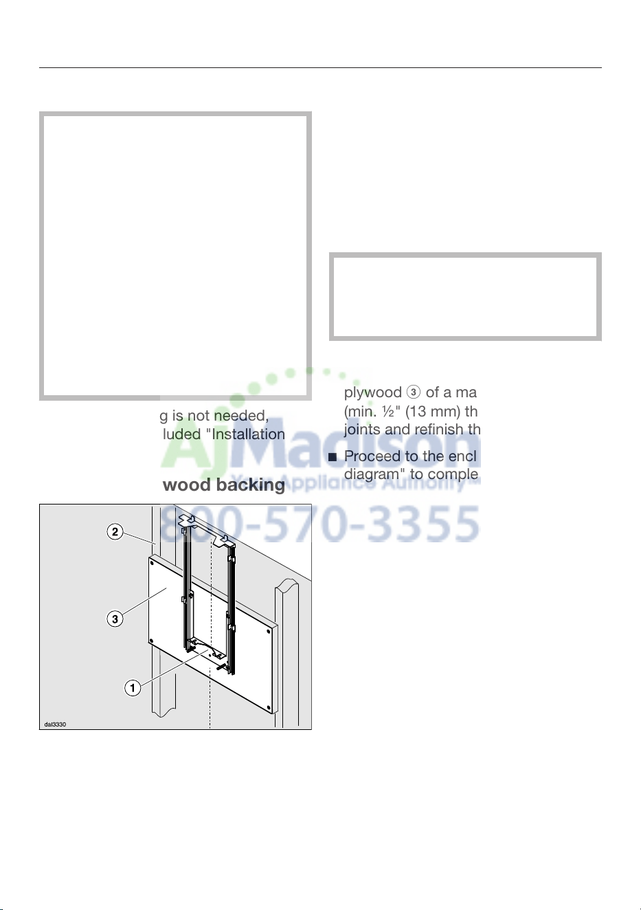
Plywood backing
The majority of the weight of the
inst
alled ventilation system will be
supported by the lower retaining
plate. It must be firmly attached to
the stud framing behind the drywall.
If studs are not available in the
required locations, a plywood
backing (min. ½" (13 mm) thick)
spanning at least two studs must be
installed.
Failure to adequately support the
weight as stated may result in the
ventilation system falling off the wall,
causing personal injury and property
damage.
If plywood backing is not needed,
proceed to the included "Installation
diagram".
To install a plywood backing
Determine and mark the location of
the retaining plate for the canopy
as outlined on the "Installation
diagram".
Make a cutting line 3" (76 mm) above
and 3" (76 mm) below the outline of
the r
etaining plate.
Find the studs to the left and right
of the mounting location by tapping
the wall or usi
ng a stud finder.
Mark a vertica
l cutting line along the
center of each stud.
CAUTION: When cutting or drilling
int
o the wall or ceiling, do not
damage electrical wiring and other
hidden utilities.
Remove the drywall between the
cuttin
g lines and replace it with
plywood of a matching thickness
(min. ½" (13 mm) thick). Tape the
joints and refinish the wall.
Proceed to the enclosed "Installation
diagr
am" to complete the installation.
Exhaust duct
31
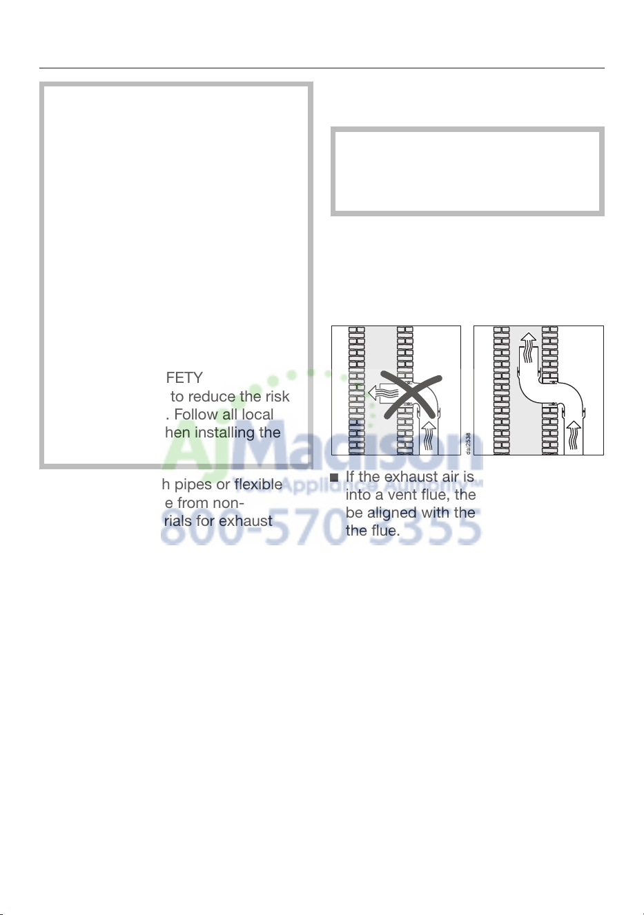
WARNING: Danger of toxic fumes.
Gas cooking appliances release
carbon monoxide that can be
harmful or fatal if inhaled.
To reduce the risk of fire and to
properly e
xhaust air, the exhaust
gases extracted by the hood should
be vented outside of the building
only.
Do not vent exhaust air into spaces
within walls or ceilings or in attics,
cr
awl spaces or ga
rages.
To reduce the risk of fire, only use
metal ductwork.
Please read and follow the
"IMPORT
ANT SAFETY
INSTRUCTIONS" to reduce the risk
of personal injury. Follow all local
building codes when installing the
hood.
Only use smooth p
ipes or flexible
duct hoses made from non-
flammable materials for exhaust
ductwork.
To achieve the greatest possible air
e
xtraction with the lowest noise
levels, please note the following:
– The diameter of the exhaust duct
should not be less than 6" (150 mm).
– If flat exhaust ducts are used, the
cross section should not be smaller
than that of the exhaust connector.
– The exhaust duct should be as short
and straigh
t as possible.
– If elbows are needed, make sure they
have
a large radius.
– The exhaust duct itself must not be
kink
ed or compressed.
– Make sure that all connections are
secur
e and airtight.
Remember that any constriction of
the air
flow will reduce extraction
performance and increase operating
noise.
If the e
xhaust duct is to be routed
thr
ough an outside wall, we
recommend installing a telescopic
wall vent or a rooftop vent (available
as an optional accessory).
If the e
xhaust air is to be conducted
int
o a vent flue, the intake piece must
be aligned with the flow direction of
the flue.
When installing the exhaust duct
horizontally, you must slope it away
from the source by at least 1 cm per
meter (3/8" per 3 1/4'). This ensures
that condensate cannot drain back
into the ventilation hood.
If the exhaust duct is to be routed
thr
ough rooms, ceiling space etc., the
temperatures in these different areas
may differ greatly, which means that
the problem of condensation will
need to be addressed. The exhaust
duct will need to be insulated.
Exhaust duct
32
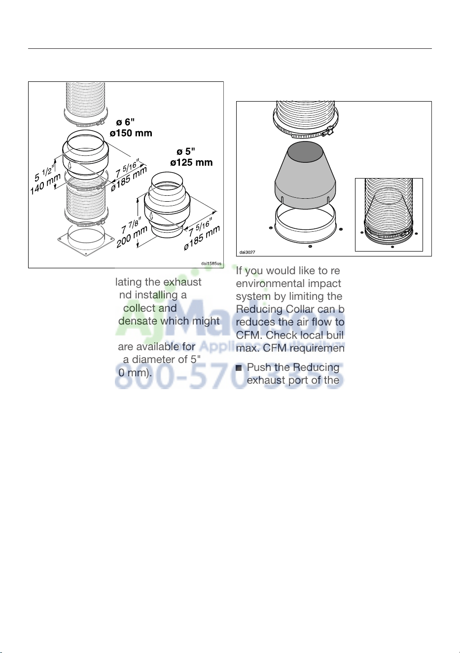
Condensate trap
In addition to insulating the exhaust
duct, we
recommend installing a
condensate trap to collect and
evaporate any condensate which might
accumulate.
Condensate traps are available for
exhaust ducts with a diameter of 5"
(125 mm) or 6" (150 mm).
When installing a co
ndensate trap,
make sure that it is positioned
vertically and, if possible, directly
above the hood outlet duct collar.
The arrow on the housing indicates
the direction of airflow.
Reducing Collar
(optional accessory)
If you would like to reduce the
envir
onmental impact of your ventilation
system by limiting the CFM output the
Reducing Collar can be installed. It
reduces the air flow to less than 400
CFM. Check local building codes for
max. CFM requirements.
Push the Reducing Collar on the
e
xhaust port of the fan.
Push the exhaust hose over it.
Fix both with a hose clamp.
Electrical connection
33
WARNING: TO REDUCE THE RISK
OF FIRE, ELECTRIC SHOCK, OR
INJURY TO PERSONS, OBSERVE
THE FOLLOWING:
All electrical work should be
performed by a q
ualified electrician
in strict accordance with national
regulations (for USA: ANSI-NFPA 70)
and local safety regulations.
Installation, repairs and other work
by unqualified persons could be
dangerous.
Ensure that power to the appliance is
OFF while
installation or repair work
is performed.
Verify that the voltage, load and
circ
uit rating information found on
the data plate (located behind the
baffle filters), match the household
electrical supply before installing the
hood.
Use only with ventilation hood cord-
connection kits that have been
in
vestigat
ed and found acceptable
for use with this model hood.
If there is any question concerning
the electrical connection of this
applianc
e t
o your power supply,
please consult a licensed electrician
or call Miele’s Technical Service
Department.
WARNING: THIS APPLIANCE MUST
BE GROUNDED
The hood comes equipped with a
power cord with a NEMA
5-15 molded
plug for connection to a 120 VAC,
60 Hz, 15 A power outlet.
Grounding Instructions
WARNING - Improper grounding can
resul
t in a risk of electric shock.
This appliance must be grounded. In
the event of an electrical shor
t circuit,
grounding reduces the risk of electric
shock by providing a path of least
resistance. This appliance is equipped
with a cord having a grounding wire
with a grounding plug.
If there is any doubt, have the electrical
system of the house
checked by a
qualified electrician.
Do not use an extension cord. If the
power suppl
y cord is too short, have a
qualified electrician install an outlet
near the appliance.
The plug must be plugged into an
outl
et that is properly installed and
grounded.
WARNING - Grounding instructions
(Cana
da)
The grounding-type attachment plug
shall be connected to a grounding-
type receptacle installed in
accordance with CSA C22.1-12,
Canadian Electrical Code, Part I.

Service and warranty
34
For faults that you cannot resolve on
your own, please contact your Miele
dealer or Mie
le T
echnical Service.
The telephone number for the Technical
Service De
partment is listed at the back
of these instructions.
When contacting Miele, please state
the model and serial number of your
ventilation hood.
These
can be found on the data plate.
Location of the data plate
The data plate is visible once you have
removed the gr
ease filters.
Warranty
For further information, please refer to
your warranty bookl
et.
Technical data
35
Fan motor 350 W
Cooktop lighting 2 x 50 W
Total connected load 450 W
Voltage, Frequency 120 V AC, 60 Hz
Fuse rating 15 A
Power cord length 2.5 ft (0.75 m)
Weight
DA 398-6 55.3 lbs (25.1 kg)
DA 399-6 57.2 lbs (26 kg)
Optional accessories for recirculation mode:
Recirc
ulation kit DUW 20 and OdorFree Charcoal Filter DKF 12


9 Independence Way
Princeton, NJ 08540
Phone:
Fax:
www.mieleusa.com
U.S.A.
Miele, Inc.
National Headquarters
Please have the model and serial number
of your appliance available before
contacting Technical Service.
Canada
Importer
Miele Limited
Headquarters and Miele Centre
800-843-7231
609-419-9898
609-419-4298
Technical Service & Support
Nationwide
Phone:
Fax:
T
echnicalService@mieleusa.com
161 Four Valley Drive
Vaughan, ON L4K 4V8
www.miele.ca
800-999-1360
888-586-8056
Customer Care Centre
Phone:
800-565-6435
905-532-2272
Germany
Manufacturer
Miele & Cie. KG
Carl-Miele-Straße 29
33332 Gütersloh
36

M.-Nr. 09 968 240 / 00en-US
DA 398-6
DA 399-6
