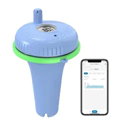

Wireless Pool Thermometer
User Manual
1.Getting Started......................................1
1.1 Parts List.........................................1
2. Battery Installation................................2
2.1 Pool Sensor.....................................2
2.1.1 Wrench Usage Instruction........9
2.2 Display Console............................14
3. Features.............................................15
3.1 Pool Sensor Features...................15
3.2 Display Console Features.............20
3.2.1 Console SET Mode................20
3.2.2 Console Alarm Mode..............23
3.2.3 Console Min/Max Mode..........26
3.2.4 Console Channel Mode..........27

3.2.5 Rate of Change Icon...............29
3.2.6 Temperature Calibration.........29
4. Sensors Operation Verification...........35
5. Best Practices for wireless transmit....35
6. Wireless Pool Sensor Placement.......37
7. Pool Sensor Maintenance...................39
8. Specifications.....................................40
9. Troubleshooting Guide.......................42
- 1 -
1.Getting Started
Note: Power up the pool sensor first,
and the Display Console second, don’t
press any button until all data is received.
1.1 Parts List
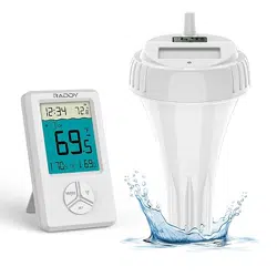
Display Console:
Size: 4.3”x2.5”x0.65” (11x6.3x1.6cm)
LCD Size: 2.1x1.7” (5.3x4.3cm)
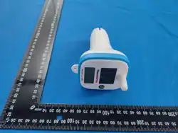
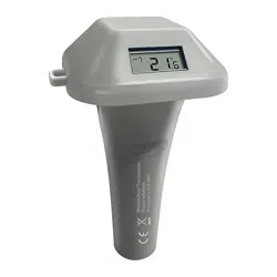
Pool transmitter
Size:6.9x4.2x3.7inch(17.5x10.6x9.5 cm)
2 x Wrench (for Upper lid and Lower lid)
Note: The pool sensor is very tight
for waterproof purpose, please use
wench to open and close it easily.

- 2 -
2. Battery Installation
2.1 Pool Sensor(Transmitter)
Note: To avoid permanent damage,
please take note of the battery polarity
before inserting the batteries.
Note: We recommend fresh lithium
batteries for sensor temperature lower
than -4 °F (-20 °C) in cold weather
environments.
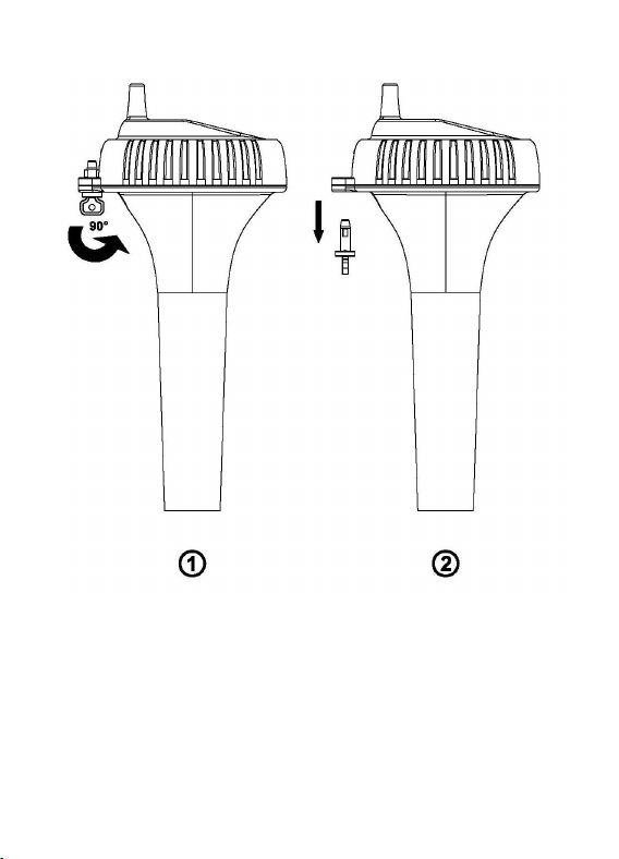
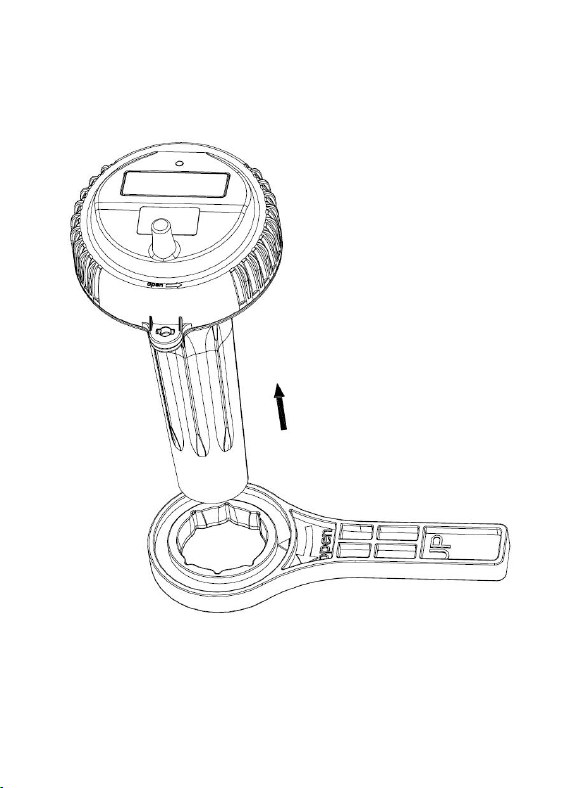
1.
To insert the batteries,
①
Twist the
KEY to unlock, ② remove the KEY, and
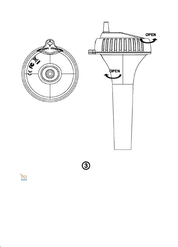
③
twist the main body of the sensor by
removing the upper lid and lower lid with
wrench(included), as shown in below
image .
- 3 -
- 4 -
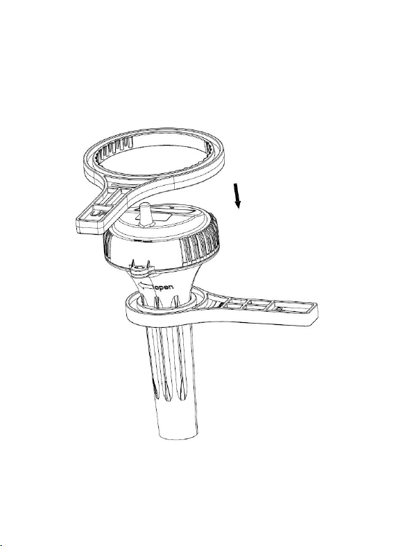
Note: Refer to Wrench Usage
Instructions to open easily along the
arrow direction
- 5 -
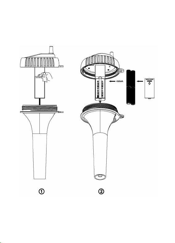
2. Install 4 x AAA batteries. (Notify
Battery polarity)
- 6 -
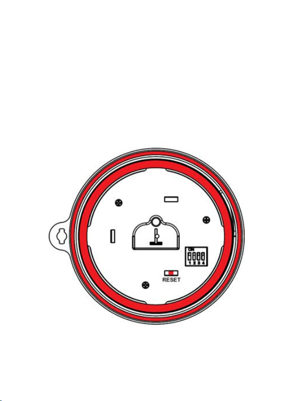
3. Before Closing battery door. Make
sure both red colored gaskets are properly
seated in their traces as shown in below
image. Failure to properly seal the floating
thermometer will result in water leakage
and damage.
- 7 -
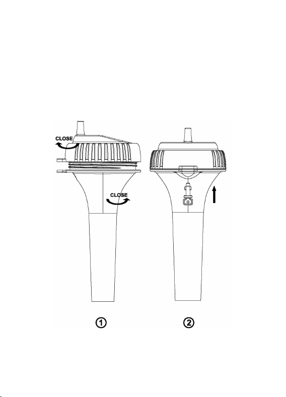
4. To close the lid, ① Twist the upper lid
and lower lid with wrench until it is firmly
locked and the key hole is aligned.
②Insert the key and turn 90 degrees to
lock the lid, as shown in below image.
- 8 -
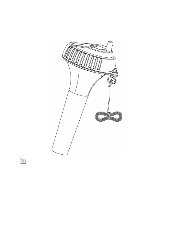
5. A tether can be added into the key hole
(Tether not included).
Note: Place the sensor in the water and
make sure that it is within the effective
transmission range( 10” (30 meters) under
most conditions) from the display console.
- 9 -
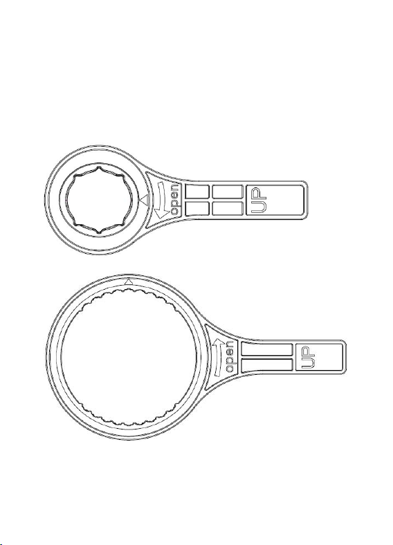
2.1.1 Wrench Usage Instructions
Please refer to the following operation.
The wrench has “UP” character facing up.
Small Wrench
Big Wrench
- 10 -
1. The small wrench and the lower cover
must be fixed in a tight direction.
- 11 -
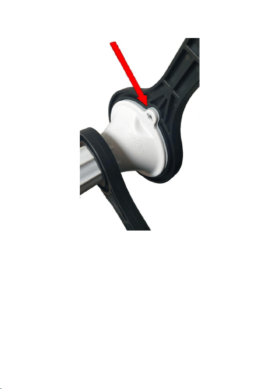
2. The big wrench and the upper cover
must match tightly, especially the arrow
positioning.
- 12 -
3. Make sure that the two wrenches are
properly matched to 90 degrees, so that it
can be opened easily.
- 13 -
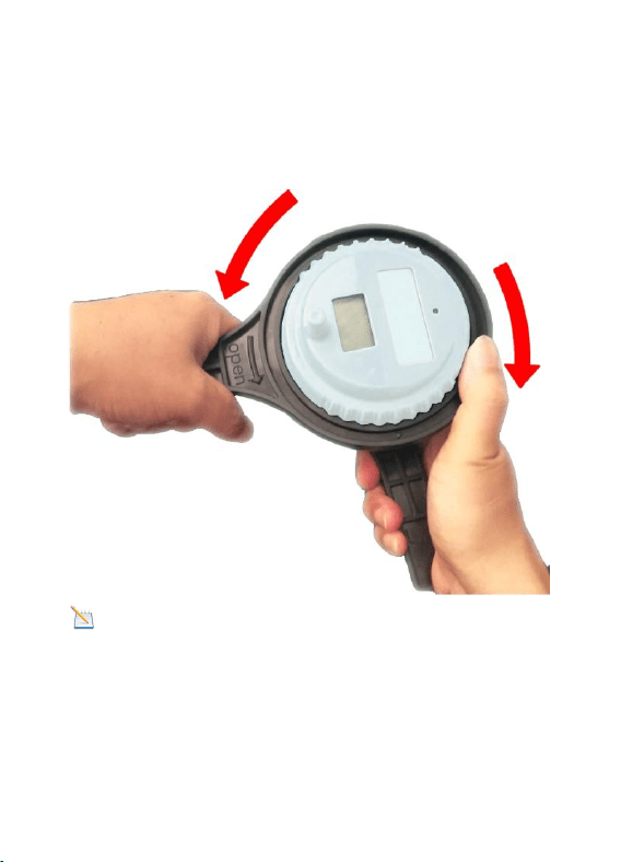
4.
Use the left hand hold the big wrench
to turning the lid counter-clockwise, Tightly
grip the small wrench with the right hand.
NOTE: You need to hold the big wrench
with your right thumb, prevent the big
wrench from slipping.
- 14 -
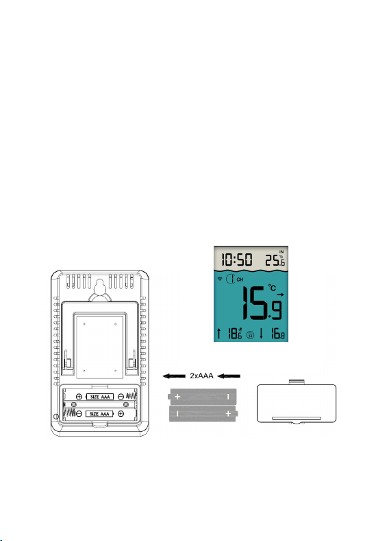
2.2 Display Console
1. Remove the battery door on the back of
the console, as shown in below image.
2. Insert 2xAAA (alkaline or lithium, avoid
rechargeable) batteries, and close the
battery door to put on desk or mount on
the wall.
3. Don’t touch any button until all the data
received.
Console Display

- 15 -
Note: Move the sensor about 5 to 10”
(1.5 to 3m) away from the display console
(if the sensor is too close, it may not be
received by the display console).
Note: If you have more than one remote
sensor, make sure they are all powered up
and transmitting on different channels.
3. Features
3.1 Pool Sensor Features
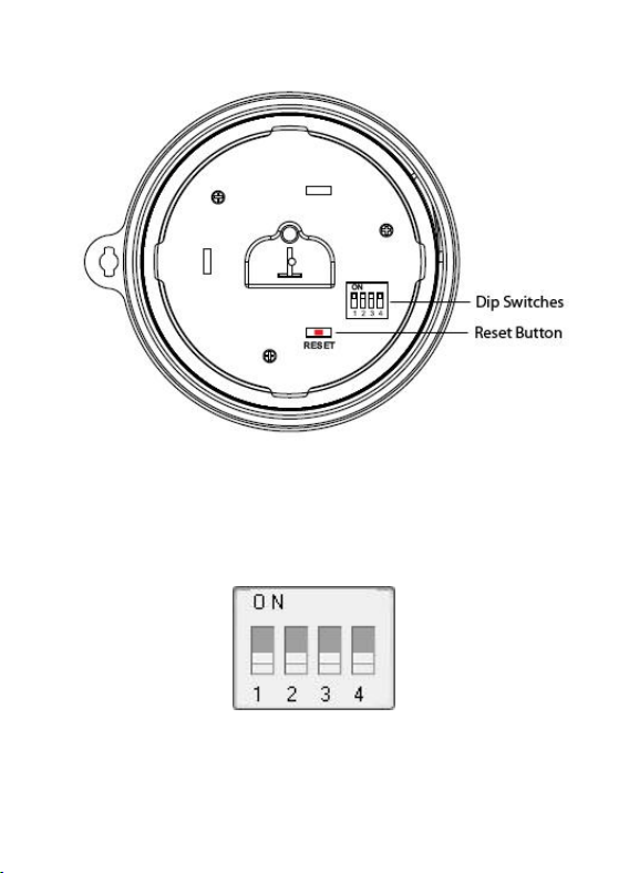
1. The Pool sensor includes dip switches
for assigning channel numbers(1-8)
2. The pool sensor includes a reset
button. If the display does not power up
after inserting the batteries, press the reset
button as shown in below image
- 16 -
3. The all four dip switches displays in
the OFF position (factory default setting) in
below image.

- 17 -
① Channel Number: Display console
supports up to eight transmitters. To set
each channel number (the default is
Channel 1), change Dip Switches 1, 2 and
3, as referenced in Table 1.
②
Temperature Units: To change the
transmitter display temp units (°F vs. °C),
change Dip Switch 4, as referenced in
Table 1.
Note: Take out batteries before
change the Channel number and C/F
unit, otherwise when batteries installed
the switch will not be effective.
- 18 -
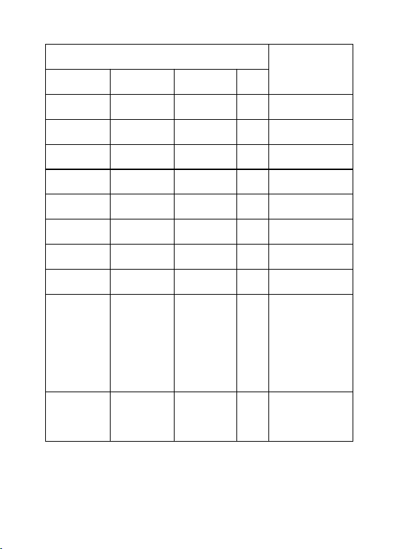
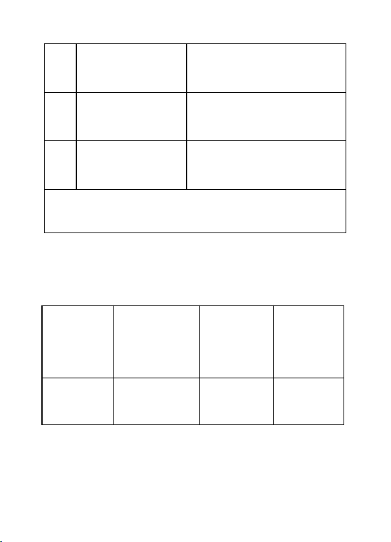
DIP SWITCH
Function
1
2
3
4
DOWN
DOWN
DOWN
---
Channel 1
DOWN
DOWN
UP
---
Channel 2
DOWN
UP
DOWN
---
Channel 3
DOWN
UP
UP
---
Channel 4
UP
DOWN
DOWN
---
Channel 5
UP
DOWN
UP
---
Channel 6
UP
UP
DOWN
---
Channel 7
UP
UP
UP
---
Channel 8
---
---
---
D
O
W
N
°F
---
---
---
U
P
°C
- 19 -
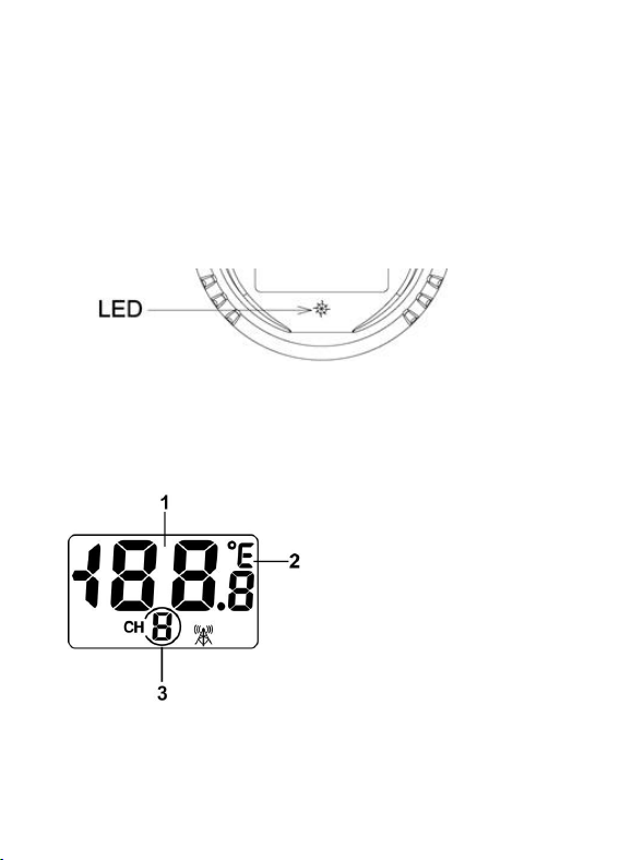
4. After inserting the batteries, the remote
sensor LED indicator will light for 4
seconds, and then flash every 60 seconds
thereafter. Each time it flashes, the sensor
is transmitting data.
5. Verify the correct channel number (CH)
and temperature units (°F vs. °C) are on
the display, as shown in below image.
(1) Temp
(2)Temp units
(°F vs. °C)
(3)channel number

- 20 -
3.2 Display Console Features
When batteries installed (Don’t Press
any button), the console will instantly
display indoor temperature and time. The
pool temperature will update on the display
within a few minutes on the appropriate
channel.
Note:
If the remote does not update,
please reference the troubleshooting guide
in Section 9.
3.2.1 Console SET Mode
Note: The console has three buttons for
easy operation: SET button, MIN/MAX
button, and CH/+ button.

- 21 -
To enter the SET mode, press and hold
the SET key for 3 seconds and 12/24 hour
format start to flash.
Short Press
SET Key to
skip entering
into the
following
features and
flash.
Press the [+] or [-]
key to set up the
following features.
1
12/24 Hour
Format
12 hour or 24 Hour
Format
2
Hour
Hour value up or
down
3
Minute
Minute value up or
down

- 22 -
4
Alarm Hour
Alarm Hour value
up or down
(While the alarm
value is flashing,
press and hold the
SET button for
three seconds to
turn alarm ON and
OFF. )
5
Alarm
Minute
Alarm Minute value
up or down
(While the alarm
value is flashing,
press and hold the
SET button for
three seconds to
- 23 -
turn the alarm ON
and OFF. )
6
Temperature
Units
°F or °C
7
Max/Min
Clearing
ON (Clears Daily)
or OFF (Manually)
Press the SET key to exit setting Mode.
3.2.2 Console ALARM Mode
1. Alarm Defaults
Channel
Default
Condition
HI
ALARM
°C(°F)
LOW
ALARM
°C(°F)
1
OFF
38(100)
15(60)
- 24 -
2
OFF
43(110)
32(90)
2. View and Set HI/Low Alarm
Note: The high and low alarms can be
set for Channels 1 and 2 only.
1) Press the CH/+ button to switch the
display between Channel 1 and 2.
2) Next, press the SET button once, the
HI/Low alarm and alarm icon
will displayed.
3) Press and hold the SET button for 3
seconds, and the temperature HIGH (Max)
alarm will flash.

- 25 -
4) Press the [+] or [-] button to increase
or decrease the HIGH alarm. Press and
hold the [+] or [-] button to change rapidly.
While the alarm value is flashing, press
and hold the SET button for three seconds
to turn alarm ON and OFF . The alarm icon
will appear when set, and disappear
when disabled.
5) Press (do not hold) the SET button
again to set the LOW (Min) temperature
alarm. The LOW alarm for temperature will
flash.
6) Press the [+] or [-] button to increase or

- 26 -
decrease the LOW alarm. Press and hold
the [+] or [-] button to change rapidly.
While the alarm value is flashing, press
and hold the SET button for three seconds
to turn alarm ON and OFF. The alarm icon
will appear when set, and disappear
when disabled.
3.2.3 Console Min/Max Mode
1) In normal mode, Press the MIN/MAX
button once and the MAX arrow will flash.
Press the MIN/MAX button again and the
MIN arrow will flash.
2) Press the MIN/MAX button again to
return to normal mode.

- 27 -
3) To reset the Max/Min values, press
and hold the MIN/MAX- button for 3
seconds.
3.2.4 Console Channel Mode
1. Channel Selection
Press the CH/+ button to switch the
display between remote sensors 1 through
8, and scroll mode . In scroll mode, all
of detected outdoor sensors will be
displayed in five second intervals.
2. Sensor Search Mode
If any of the sensor communication is lost,
dashes (--.-) will be displayed on the
screen. To reacquire the signal:
- 28 -
1) If a specific channel is lost, press the
CH/+ button to display this channel, then
Press and hold the CH/+ button for 3
seconds, and remote search icon will
be constantly displayed for up to 3 minutes.
Once the signal is reacquired, the remote
search icon will turn off, and the
current values will be displayed.
2) If new sensors are added, subtracted,
or multiple sensor channels are lost, Press
and hold the CH/+ button for 5 seconds
(on any channel), and remote search icon
will be constantly displayed for up to
10 minutes. Once the signal is reacquired,
the remote search icon will turn off,
and the current values will be displayed.

- 29 -
3.2.5 Rate of Change Icon
The rate of change icon detects rapid
changes of remote temperature. If the
arrow points upward, the temperature is
increasing at a rate of +2°C(4°F) per 30
minutes (or greater), If the arrow points
downward, the temperature is decreasing
at a rate of -2°C(4°F) per 30 minutes (or
less).
3.2.6 Temperature Calibration
1. Pool Sensor Temp Calibration
1)
Prior to entering the calibration mode,
press the CH/+ button to select the pool
temperature sensor(CH1-8) you wish to
adjust.

- 30 -
2) To enter the temperature calibration
mode, press and hold the SET and CH/+
buttons at the same time for 5 seconds
and the pool temperature value will begin
flashing. Press the CH/+ button to increase
the temperature and the MIN/MAX button
to decrease the temperature reading in
0.1° increments. To rapidly increase (or
decrease) the temperature reading, press
and hold the CH/+ or MIN/MAX button.
3) To return the temperature to the actual
or uncalibrated measurement, press the
SET button.
4) Once the displayed temperature equals
the calibrated source, press and hold the

- 31 -
SET button for three seconds, or wait 15
seconds for timeout, and the temperature
value will stop flashing.
2. Indoor Temperature Calibration
1) To enter the indoor temperature
calibration mode, press and hold the SET
and MIN/MAX buttons at the same time for
5 seconds and the IN temperature value
will begin flashing. Press the CH/+ button
to increase the temperature and the
MIN/MAX button to decrease the
temperature reading in 0.1° increments. To
rapidly increase (or decrease) the
temperature reading, press and hold the
CH/+ or MIN/MAX button.

- 32 -
2) To return the temperature to the actual
or uncalibrated measurement, press the
SET button.
3) Once the displayed temperature equals
the calibrated source, press and hold the
SET button for three seconds, or wait 15
seconds for timeout, and the temperature
value will stop flashing.
Note: The calibrated value can only be
adjusted on the console. The remote
sensor always displays the un-calibrated
or measured value.
The purpose of calibration is to fine tune or
correct for any sensor error associated

- 33 -
with the devices margin of error. The
measurement can be adjusted from the
console to calibrate to a known source.
Calibration is only useful if you have a
known calibrated source you can compare
it against, and is optional. This section
discusses practices, procedures and
sources for sensor calibration to reduce
manufacturing and degradation errors. Do
not compare your readings obtained from
sources such as the internet, radio,
television or newspapers. They are in a
different location and typically update once
per hour.
The purpose of your weather station is to

- 34 -
measure conditions of your surroundings,
which vary significantly from location to
location.
Discussion: Temperature errors can
occur when a sensor is placed too close to
a heat source (such as a building structure,
the ground or trees).
To calibrate temperature, we recommend a
mercury or red spirit (fluid) thermometer.
Bi-metal (dial) and other digital
thermometers are not a good source and
have their own margin of error. Using a
local weather station in your area is also a
poor source due to changes in location,
timing (airport weather stations are only

- 35 -
updated once per hour) and possible
calibration errors (many official weather
stations are not properly installed and
calibrated).
4. Sensor Operation Verification
Verify the indoor and sensor temperature
match closely with the console and sensor
array in the same location (about 1.5 to
3meters apart). The sensors should be
within 2°C/4°F (the accuracy is ±1°C/2°F).
Allow about 30 minutes for both sensors to
stabilize.
5. Best Practices for Wireless Transmit
Wireless communication is susceptible
to interference, distance, walls and metal

- 36 -
barriers. We recommend the following best
practices for trouble free wireless
communication.
1. Electro-Magnetic Interference (EMI).
Keep the console several feet away from
computer monitors and TVs.
2. Radio Frequency Interference (RFI).
If you have other 433 MHz devices and
communication is intermittent, try turning
off these other devices for troubleshooting
purposes. You may need to relocate the
transmitters or receivers to avoid
intermittent communication.
3. Line of Sight Rating. This device is
rated at 50meters line of sight (no
interference, barriers or walls) but typically

- 37 -
you will get 30meters maximum under
most real-world installations, which include
passing through barriers or walls.
4. Metal Barriers. Radio frequency will
not pass through metal barriers such as
aluminum siding. If you have metal siding,
align the remote and console through a
window to get a clear line of sight.
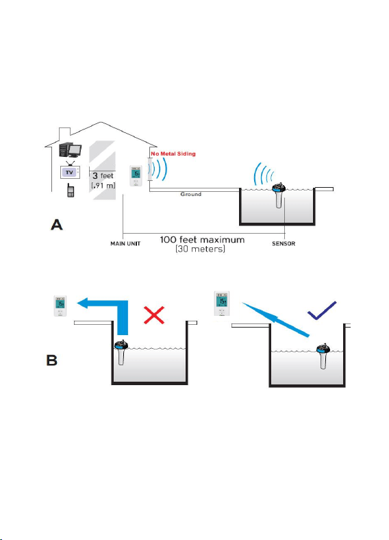
6. Wireless Pool Sensor Placement
1. Place the sensor in the pool or spa
within 30meters of the display console
(Reference A). Avoid transmitting through
solid earth or ground (Reference B).
2. Place the console at least three feet
away from computers, TVs and wireless
phones.
- 38 -
3. Avoid transmitting through solid metal
barriers.

- 39 -
7. Pool Sensor Maintenance
During each battery change (1-2 years),
we recommend applying waterproof silicon
grease to the seals:
http://en.wikipedia.org/wiki/Silicone_grease
Silicone grease is available at most
hardware and pool stores.
Note: Not recommended for covered
spas. Wireless signal will not penetrate
solid metal or earth.

- 40 -
8.Specifications
1. Wireless Specifications
1) Line of sight wireless transmission (in
open air): 165 feet (50m), 100 feet (30m)
under most conditions.
2) Frequency: 433 MHz
3) Update Rate: 60 seconds
2. Measurement Specifications
Measurement
Range
Accuracy
(Resolution)
Indoor
Temperature
32 to 140 °F
(0°-60°C)
±2°F/±1°C
(0.1 °F/°C)
Outdoor
Temperature
-40 to
140 °F
(-40°-60°C)
±2°F/±1°C
(0.1 °F/°C)

- 41 -
3. Power Consumption
Base station (display console): 2 x AAA
1.5V Alkaline or Lithium batteries (not
included)
Pool sensor: 4 x AAA 1.5V Alkaline or
Lithium batteries (not included)
Battery life: Minimum 12 months for base
station. Intermittent reception and multiple
sensors may reduce the battery life.
Minimum 12 months for pool sensor (use
lithium batteries in cold weather climates
less than -4 °F/-20°C)
- 42 -
9. Troubleshooting Guide
Wireless remote (thermometer) not
reporting in to console. There are
dashes (---) on the display console.
Solution
If any of the sensor communication is
lost, dashes (--.-) will be displayed on
the screen. To reacquire the signal,
press and hold the CH/+ button for 3
seconds, and the remote search icon
will be constantly displayed. Once
the signal is reacquired, the remote
search icon will turn off, and the
current values will be displayed.
The maximum line of sight transmit

- 43 -
range is 165’(50m) and 100’(30m)
under most conditions. Move the sensor
assembly closer to the display console.
If the sensor assembly is too close
(less than 5’/1.5m), move the sensor
assembly away from the console.
Make sure the remote sensor LCD
display is working and the transmitter
light is flashing once per 60 seconds.
Install a fresh set of batteries in the
remote thermometer. For cold weather
environments, install lithium batteries.
Make sure the remote sensors are not

- 44 -
transmitting through solid metal (acts as
an RF shield), or earth barrier (down a
hill).
Move the display console around
electrical noise generating devices,
such as computers, TVs and other
wireless transmitters or receivers.
Move the remote sensor to a higher
location. Move the remote sensor to a
closer location.
Indoor and Outdoor Temperature do
not agree
Solution
Allow up to one hour for the sensors to

- 45 -
stabilize due to signal filtering. The
indoor and outdoor temperature sensors
should agree within 4°F/2°C(the sensor
accuracy is ±2°F/1
°C
).
Use the calibration feature to match the
indoor and outdoor temperature to a
known source.
Display console contrast is weak
Solution
Replace console batteries with a fresh
set of batteries.

- 46 -