
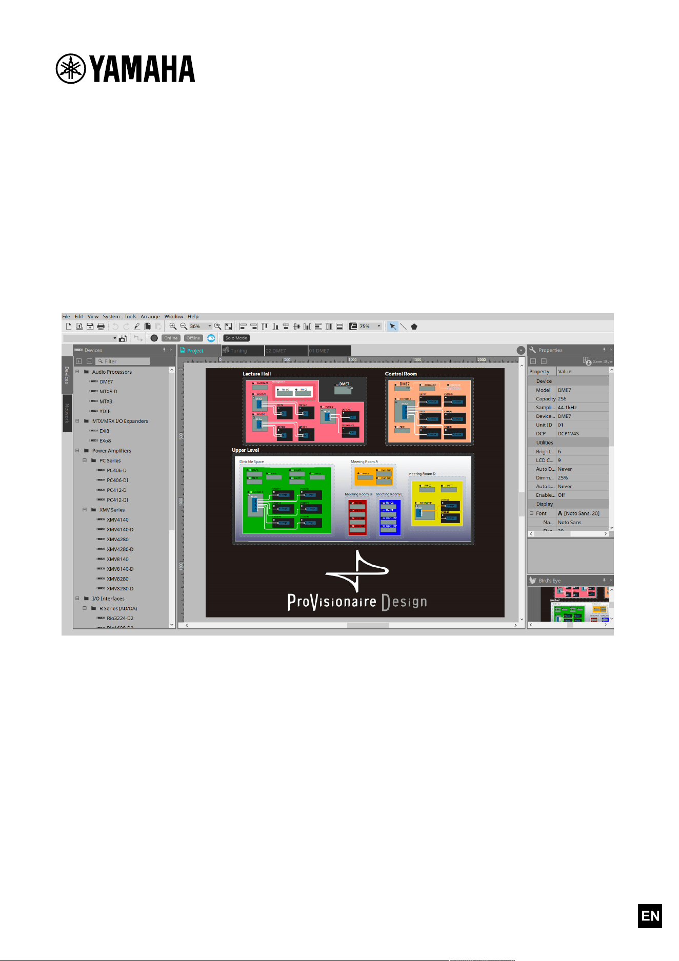
ProVisionaire Design
Component Guide

Contents
1. Introduction . . . . . . . . . . . . . . . . . . . . . . . . . . . . . . . . . . . . . . . . . . . . . . . . . . . . . . . . . . . . . . . . . . . . . . . . . Ê3
2. Audio Components . . . . . . . . . . . . . . . . . . . . . . . . . . . . . . . . . . . . . . . . . . . . . . . . . . . . . . . . . . . . . . . . . . . . Ê4
2.1. The Difference Between Mono, Stereo, and Multi . . . . . . . . . . . . . . . . . . . . . . . . . . . . . . . . . . . . . . Ê4
2.2. How to Control Control Signals . . . . . . . . . . . . . . . . . . . . . . . . . . . . . . . . . . . . . . . . . . . . . . . . . . . . . Ê5
2.3. Acoustic Echo Canceller (AEC). . . . . . . . . . . . . . . . . . . . . . . . . . . . . . . . . . . . . . . . . . . . . . . . . . . . . . Ê7
2.4. AFC Image . . . . . . . . . . . . . . . . . . . . . . . . . . . . . . . . . . . . . . . . . . . . . . . . . . . . . . . . . . . . . . . . . . . . . Ê13
2.5. Ambient Noise Compensator (ANC) . . . . . . . . . . . . . . . . . . . . . . . . . . . . . . . . . . . . . . . . . . . . . . . . . Ê14
2.6. Audio Detector . . . . . . . . . . . . . . . . . . . . . . . . . . . . . . . . . . . . . . . . . . . . . . . . . . . . . . . . . . . . . . . . . Ê17
2.7. Auto Gain Control (AGC) . . . . . . . . . . . . . . . . . . . . . . . . . . . . . . . . . . . . . . . . . . . . . . . . . . . . . . . . . Ê19
2.8. Combiner: Room Combiner, Room Combiner plus Automixer . . . . . . . . . . . . . . . . . . . . . . . . . . . . . Ê22
2.9. DCA . . . . . . . . . . . . . . . . . . . . . . . . . . . . . . . . . . . . . . . . . . . . . . . . . . . . . . . . . . . . . . . . . . . . . . . . . . Ê32
2.10. Delay . . . . . . . . . . . . . . . . . . . . . . . . . . . . . . . . . . . . . . . . . . . . . . . . . . . . . . . . . . . . . . . . . . . . . . . . Ê34
2.11. Dynamics: Compressor . . . . . . . . . . . . . . . . . . . . . . . . . . . . . . . . . . . . . . . . . . . . . . . . . . . . . . . . . . Ê36
2.12. Dynamics: Comp260 . . . . . . . . . . . . . . . . . . . . . . . . . . . . . . . . . . . . . . . . . . . . . . . . . . . . . . . . . . . . Ê39
2.13. Dynamics: De-Esser . . . . . . . . . . . . . . . . . . . . . . . . . . . . . . . . . . . . . . . . . . . . . . . . . . . . . . . . . . . . Ê42
2.14. Dynamics: Ducker . . . . . . . . . . . . . . . . . . . . . . . . . . . . . . . . . . . . . . . . . . . . . . . . . . . . . . . . . . . . . . Ê44
2.15. Dynamics: Gate . . . . . . . . . . . . . . . . . . . . . . . . . . . . . . . . . . . . . . . . . . . . . . . . . . . . . . . . . . . . . . . . Ê47
2.16. Dynamics: Limiter . . . . . . . . . . . . . . . . . . . . . . . . . . . . . . . . . . . . . . . . . . . . . . . . . . . . . . . . . . . . . . Ê50
2.17. Dynamics: Paging Ducker . . . . . . . . . . . . . . . . . . . . . . . . . . . . . . . . . . . . . . . . . . . . . . . . . . . . . . . . Ê53
2.18. Dynamics: Program Ducker. . . . . . . . . . . . . . . . . . . . . . . . . . . . . . . . . . . . . . . . . . . . . . . . . . . . . . . Ê55
2.19. Effect: Ping Pong Delay . . . . . . . . . . . . . . . . . . . . . . . . . . . . . . . . . . . . . . . . . . . . . . . . . . . . . . . . . Ê58
2.20. Effect: REV-X . . . . . . . . . . . . . . . . . . . . . . . . . . . . . . . . . . . . . . . . . . . . . . . . . . . . . . . . . . . . . . . . . Ê60
2.21. EQ: GEQ. . . . . . . . . . . . . . . . . . . . . . . . . . . . . . . . . . . . . . . . . . . . . . . . . . . . . . . . . . . . . . . . . . . . . . Ê63
2.22. EQ: PEQ . . . . . . . . . . . . . . . . . . . . . . . . . . . . . . . . . . . . . . . . . . . . . . . . . . . . . . . . . . . . . . . . . . . . . . Ê65
2.23. Fader . . . . . . . . . . . . . . . . . . . . . . . . . . . . . . . . . . . . . . . . . . . . . . . . . . . . . . . . . . . . . . . . . . . . . . . . Ê67
2.24. Feedback Suppressor: Notch FBS. . . . . . . . . . . . . . . . . . . . . . . . . . . . . . . . . . . . . . . . . . . . . . . . . . Ê69
2.25. Feedback Suppressor: Pitch Shift FBS . . . . . . . . . . . . . . . . . . . . . . . . . . . . . . . . . . . . . . . . . . . . . Ê72
2.26. Filter: BPF . . . . . . . . . . . . . . . . . . . . . . . . . . . . . . . . . . . . . . . . . . . . . . . . . . . . . . . . . . . . . . . . . . . . Ê74
2.27. Filter: HPF . . . . . . . . . . . . . . . . . . . . . . . . . . . . . . . . . . . . . . . . . . . . . . . . . . . . . . . . . . . . . . . . . . . . Ê76
2.28. Filter: LPF . . . . . . . . . . . . . . . . . . . . . . . . . . . . . . . . . . . . . . . . . . . . . . . . . . . . . . . . . . . . . . . . . . . . Ê78
2.29. Input/Output: Dante In . . . . . . . . . . . . . . . . . . . . . . . . . . . . . . . . . . . . . . . . . . . . . . . . . . . . . . . . . Ê80
2.30. Input/Output: USB In . . . . . . . . . . . . . . . . . . . . . . . . . . . . . . . . . . . . . . . . . . . . . . . . . . . . . . . . . . . Ê81
2.31. Input/Output: Dante Out. . . . . . . . . . . . . . . . . . . . . . . . . . . . . . . . . . . . . . . . . . . . . . . . . . . . . . . . Ê82
2.32. Input/Output: USB Out . . . . . . . . . . . . . . . . . . . . . . . . . . . . . . . . . . . . . . . . . . . . . . . . . . . . . . . . . Ê84
2.33. Input/Output: SD Card. . . . . . . . . . . . . . . . . . . . . . . . . . . . . . . . . . . . . . . . . . . . . . . . . . . . . . . . . . Ê86
2.34. Meter . . . . . . . . . . . . . . . . . . . . . . . . . . . . . . . . . . . . . . . . . . . . . . . . . . . . . . . . . . . . . . . . . . . . . . . . Ê92
2.35. Mixer: Delay Matrix, Matrix Mixer . . . . . . . . . . . . . . . . . . . . . . . . . . . . . . . . . . . . . . . . . . . . . . . . Ê94
2.36. Mixer: Dugan Automixer. . . . . . . . . . . . . . . . . . . . . . . . . . . . . . . . . . . . . . . . . . . . . . . . . . . . . . . . Ê101
2.37. Oscillator . . . . . . . . . . . . . . . . . . . . . . . . . . . . . . . . . . . . . . . . . . . . . . . . . . . . . . . . . . . . . . . . . . . Ê105
2.38. Polarity . . . . . . . . . . . . . . . . . . . . . . . . . . . . . . . . . . . . . . . . . . . . . . . . . . . . . . . . . . . . . . . . . . . . . Ê107
2.39. Probe . . . . . . . . . . . . . . . . . . . . . . . . . . . . . . . . . . . . . . . . . . . . . . . . . . . . . . . . . . . . . . . . . . . . . . . Ê108
2.40. Router . . . . . . . . . . . . . . . . . . . . . . . . . . . . . . . . . . . . . . . . . . . . . . . . . . . . . . . . . . . . . . . . . . . . . . Ê110
2.41. Source Selector. . . . . . . . . . . . . . . . . . . . . . . . . . . . . . . . . . . . . . . . . . . . . . . . . . . . . . . . . . . . . . . Ê112
2.42. Speaker Processor: Standard SPP . . . . . . . . . . . . . . . . . . . . . . . . . . . . . . . . . . . . . . . . . . . . . . . . Ê114
2.43. Speaker Processor: C-Series SPP (FIR) . . . . . . . . . . . . . . . . . . . . . . . . . . . . . . . . . . . . . . . . . . . . Ê121
3. Control Components . . . . . . . . . . . . . . . . . . . . . . . . . . . . . . . . . . . . . . . . . . . . . . . . . . . . . . . . . . . . . . . . Ê123
3.1. Control Methods for Control Components . . . . . . . . . . . . . . . . . . . . . . . . . . . . . . . . . . . . . . . . . . Ê123
3.2. Input (Normalized Value): Button . . . . . . . . . . . . . . . . . . . . . . . . . . . . . . . . . . . . . . . . . . . . . . . . . Ê125
Contents
ProVisionaire Design Component Guide | 1

3.3. Input (Value): Button . . . . . . . . . . . . . . . . . . . . . . . . . . . . . . . . . . . . . . . . . . . . . . . . . . . . . . . . . . . Ê126
3.4. Input (Normalized Value): Radio Button . . . . . . . . . . . . . . . . . . . . . . . . . . . . . . . . . . . . . . . . . . . . Ê128
3.5. Input (Value): Radio Button . . . . . . . . . . . . . . . . . . . . . . . . . . . . . . . . . . . . . . . . . . . . . . . . . . . . . . Ê130
3.6. Input (Normalized Value): Fader . . . . . . . . . . . . . . . . . . . . . . . . . . . . . . . . . . . . . . . . . . . . . . . . . . Ê132
3.7. Input (Value): Fader . . . . . . . . . . . . . . . . . . . . . . . . . . . . . . . . . . . . . . . . . . . . . . . . . . . . . . . . . . . . Ê133
3.8. Processing (Normalized Value): Logic . . . . . . . . . . . . . . . . . . . . . . . . . . . . . . . . . . . . . . . . . . . . . . Ê135
3.9. Processing (Normalized Value): NOT. . . . . . . . . . . . . . . . . . . . . . . . . . . . . . . . . . . . . . . . . . . . . . . Ê137
3.10. Processing (Normalized Value): Flip-Flop . . . . . . . . . . . . . . . . . . . . . . . . . . . . . . . . . . . . . . . . . . Ê138
3.11. Processing (Normalized Value): Invert . . . . . . . . . . . . . . . . . . . . . . . . . . . . . . . . . . . . . . . . . . . . Ê140
3.12. Processing (Normalized Value): Compare . . . . . . . . . . . . . . . . . . . . . . . . . . . . . . . . . . . . . . . . . . Ê141
3.13. Processing (Normalized Value): Difference . . . . . . . . . . . . . . . . . . . . . . . . . . . . . . . . . . . . . . . . Ê143
3.14. Processing (Normalized Value): Max/Min . . . . . . . . . . . . . . . . . . . . . . . . . . . . . . . . . . . . . . . . . . Ê144
3.15. Processing (Value): Negate . . . . . . . . . . . . . . . . . . . . . . . . . . . . . . . . . . . . . . . . . . . . . . . . . . . . . Ê145
3.16. Processing (Value): Compare . . . . . . . . . . . . . . . . . . . . . . . . . . . . . . . . . . . . . . . . . . . . . . . . . . . . Ê147
3.17. Processing (Value): Multi Compare . . . . . . . . . . . . . . . . . . . . . . . . . . . . . . . . . . . . . . . . . . . . . . . Ê149
3.18. Processing (Value): Difference . . . . . . . . . . . . . . . . . . . . . . . . . . . . . . . . . . . . . . . . . . . . . . . . . . Ê151
3.19. Processing (Value): Max/Min . . . . . . . . . . . . . . . . . . . . . . . . . . . . . . . . . . . . . . . . . . . . . . . . . . . . Ê152
3.20. Processing: Delay . . . . . . . . . . . . . . . . . . . . . . . . . . . . . . . . . . . . . . . . . . . . . . . . . . . . . . . . . . . . . Ê153
3.21. Processing: External Events . . . . . . . . . . . . . . . . . . . . . . . . . . . . . . . . . . . . . . . . . . . . . . . . . . . . Ê155
3.22. Processing: Suspend . . . . . . . . . . . . . . . . . . . . . . . . . . . . . . . . . . . . . . . . . . . . . . . . . . . . . . . . . . . Ê157
3.23. Processing: Router . . . . . . . . . . . . . . . . . . . . . . . . . . . . . . . . . . . . . . . . . . . . . . . . . . . . . . . . . . . . Ê158
3.24. Controller: GPI In . . . . . . . . . . . . . . . . . . . . . . . . . . . . . . . . . . . . . . . . . . . . . . . . . . . . . . . . . . . . . Ê160
3.25. Controller: GPI Out . . . . . . . . . . . . . . . . . . . . . . . . . . . . . . . . . . . . . . . . . . . . . . . . . . . . . . . . . . . Ê162
3.26. Controller: Scheduler . . . . . . . . . . . . . . . . . . . . . . . . . . . . . . . . . . . . . . . . . . . . . . . . . . . . . . . . . . Ê164
3.27. Parameter Set. . . . . . . . . . . . . . . . . . . . . . . . . . . . . . . . . . . . . . . . . . . . . . . . . . . . . . . . . . . . . . . . Ê168
3.28. Snapshot . . . . . . . . . . . . . . . . . . . . . . . . . . . . . . . . . . . . . . . . . . . . . . . . . . . . . . . . . . . . . . . . . . . . Ê169
Contents
2 | ProVisionaire Design Component Guide

1. Introduction
This document explains how to use the audio components and control components that are supported
by the DME.
For other devices such as processors and amplifiers, several of the components used by the DME7 are
common with these devices, so you will be able to understand how to use them by reading this
document.
Information
* The illustrations and screens as shown in this guide are for instructional purposes only.
* Dante® is registered trademarks of Audinate Pty Ltd.
* Smaart is registered trademarks of Rational Acoustics, LLC.
* The company names and product names in this manual are the trademarks or registered trademarks
of their respective companies.
* Software may be revised and updated without prior notice. The application software may be updated
without notice for improvement. The latest application software can be downloaded from the Yamaha
Pro Audio website.
https://www.yamahaproaudio.com/
1. Introduction
ProVisionaire Design Component Guide | 3
2. Audio Components
2.1. The Difference Between Mono, Stereo, and Multi
Here we explain the screen for the components/editors handled by the DME.
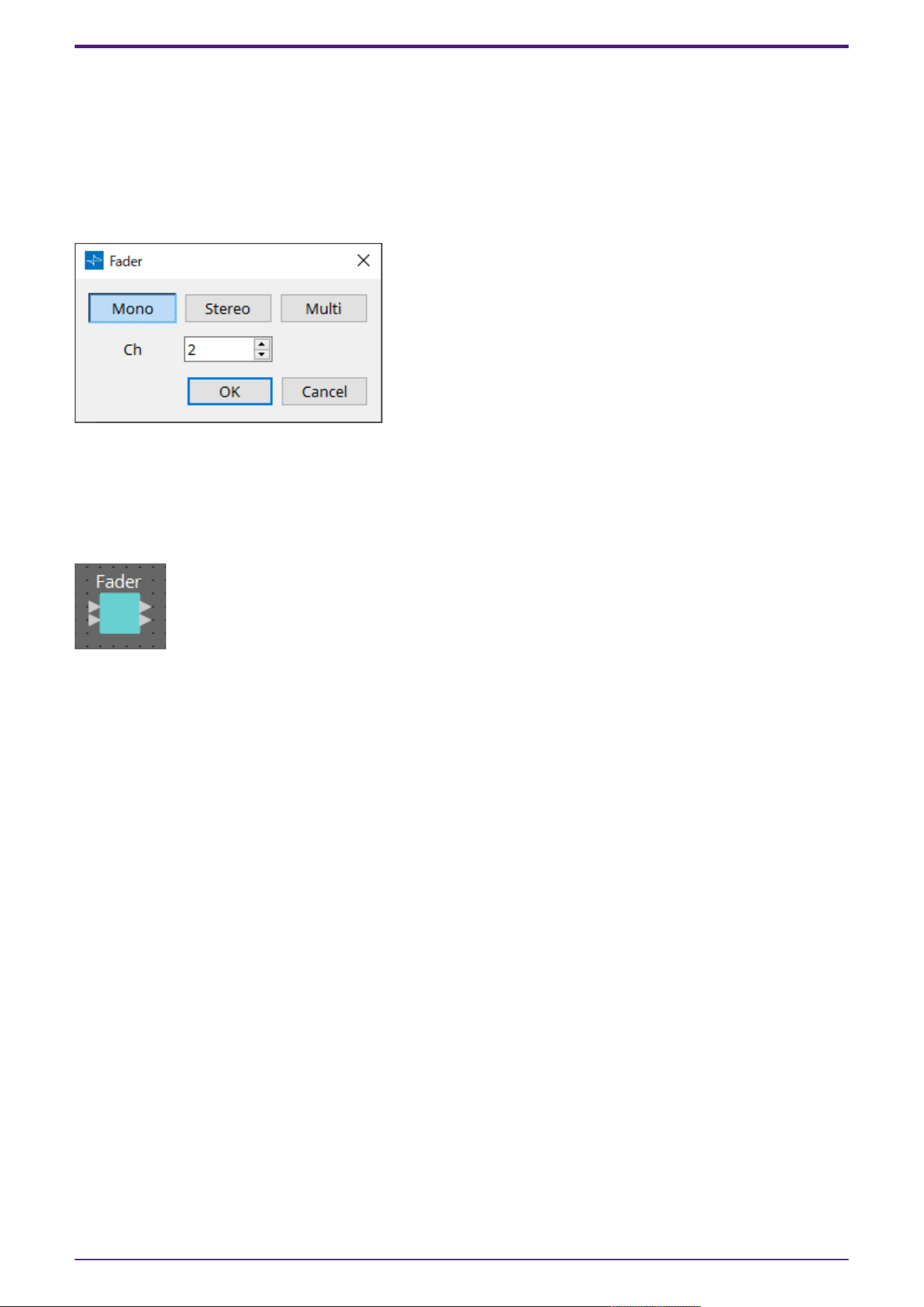
When a component is placed on the design sheet, the following screen will initially be displayed.
(Example: Fader)
These components can control multiple channels (Ch) either individually or collectively by specifying
Mono, Stereo, or Multi. For example, with a fader, selecting Stereo allows the control of L and R with a
single fader, while selecting Multi allows for all channels to be controlled at the same time with a
single fader.
When you press the [OK] button, the component is displayed.
2. Audio Components
4 | ProVisionaire Design Component Guide
2.2. How to Control Control Signals
The DME uses an area called the Control Layer to connect control component and audio component
parameters, and which makes the creation of complex control signal configurations possible.
Refer to the ProVisionaire Design User Guide for the procedures. Refer to the description in this
manual for each audio component for information about the behavior when the audio parameters are
controlled in the Control layer.
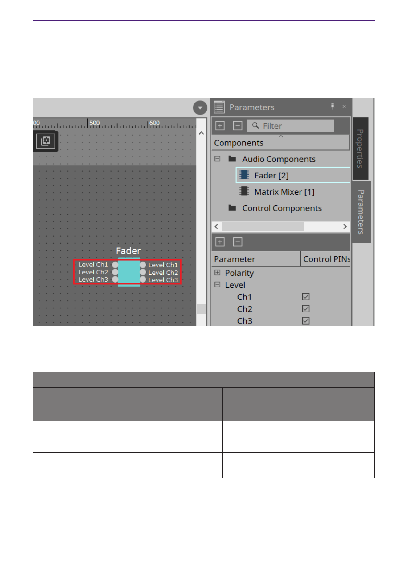
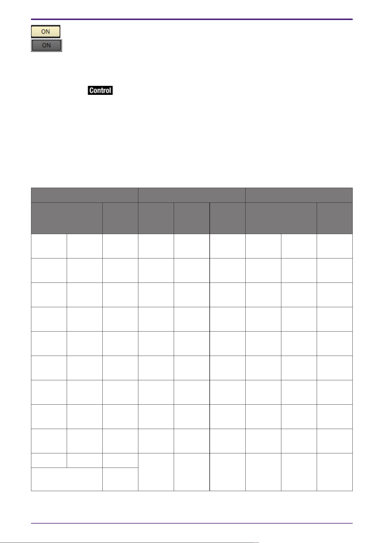
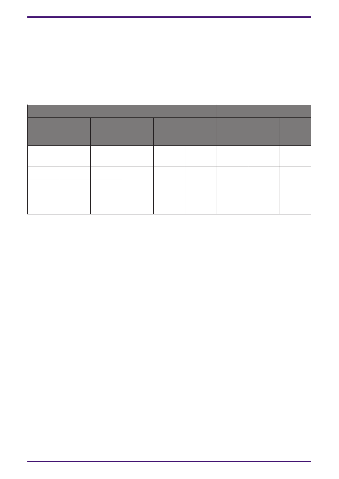
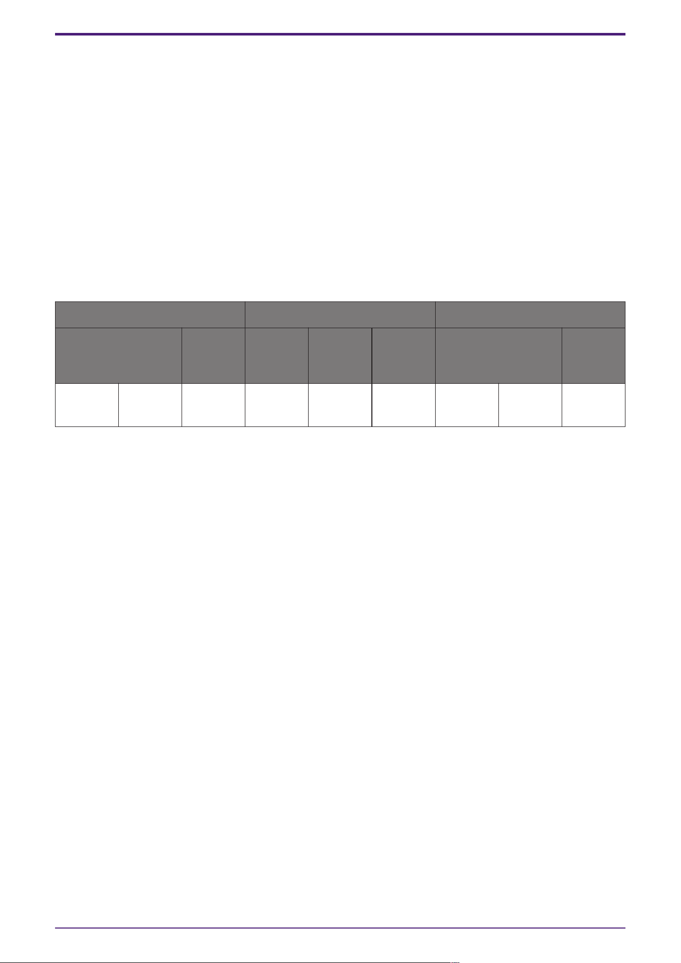
2.2.1. control
Parameter types of the input/output values for each Port
Input Value Control Parameter Output Value
Type Range Input
Port
Name
Paramete
r Range
Output
Port
Name
Type Range
Value dB −∞–10.00 ● Level
Ch1
−∞–10.00 ● Level
Ch1
Value dB −∞–10.00
Normalized 0.00–1.00
Value Num 0,1 ● On Ch1
OFF:0,
ON:1
● On Ch1 Value Num
OFF:0,
ON:1
(Example: Fader component)
On the Control layer, when the audio component parameter receives a signal, the output value is
different depending on the type of signal.
Here we will use Table 1 to explain the control method with the fader value of the Fader component as
an example. The meanings of each the columns in the table are described below.
2. Audio Components
ProVisionaire Design Component Guide | 5
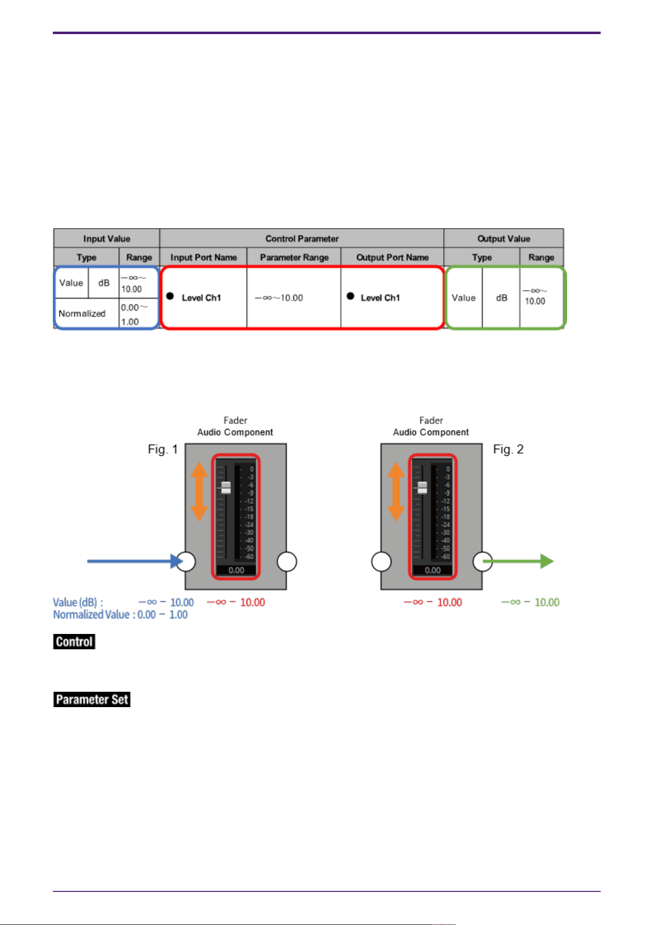
•
Control Parameter (Red outline): Audio component parameter
This shows the name of the port used to input the control signal from an external source (Input
Port Name), the name of the port that outputs the change notification (Output Port Name), and
the range of the parameter that will be controlled (Parameter range).
•
Input Value (Blue outline):
Recommended data type and range for the input value used to control the target parameter.
•
Output Value (Green outline):
Data type and range for the output value that is output to the target parameter when it is
controlled.
(Table 1)
When controlling the Level using the Fader, by inputting either a dB value (–∞ to 10.00) of the same
data type as the Level parameter you want to control, or inputting a normalized value (0.00 to 1.00),
the Fader Level can be controlled in the range of –∞ to 10.00. (Fig. 1)
Conversely, by changing the Level of the Fader, a dB value (–∞ to 10.00) is output. (Fig. 2)
Icon
Audio component parameters that have this icon can be controlled using the Control layer by putting a
check in Control PINs.
Icon
Control component parameters that have this icon can be registered to a Parameter Set, GPI, DCP, or
Remote Control Setup List.
2. Audio Components
6 | ProVisionaire Design Component Guide
2.3. Acoustic Echo Canceller (AEC)
Acoustic Echo Canceller (AEC) is a function that eliminates the acoustic echo that can be a problem
during remote conferencing when sound from a speaker is picked up by microphones, or steady-state
noise such as produced by air conditioning systems. By providing the other party with clear audio from
which such echo and noise have been removed, conversation during the remote conference can be
conducted smoothly.
In order to eliminate acoustic echo that originates with the other party, the other party must also be
equipped with a system that provides an acoustic echo canceller function.
The following amount of delay is added to a signal path in which the AEC component is placed.
When word clock is 44.1 kHz: 17.41 msec
When word clock is 48 kHz: 16.0 msec
When word clock is 88.2 kHz: 17.41 msec
When word clock is 96 kHz: 16.0 msec
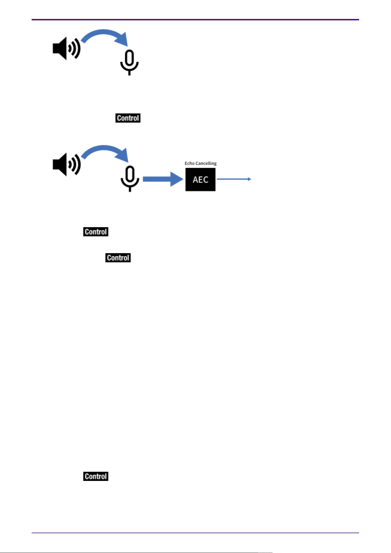
Here we explain using an image of 2-channel input.
The AEC inputs are as follows, starting from the top.
• MicIn 1 : Input from mic
• MicIn 2 : Input from mic
• Reference : Input for the signal that you do not want transmitted to the remote location (signal
that is considered as echo, and is to be removed) (e.g., Codec In)
Use mics from the same conference room as the input to MicIn 1 and MicIn 16.
2. Audio Components
ProVisionaire Design Component Guide | 7
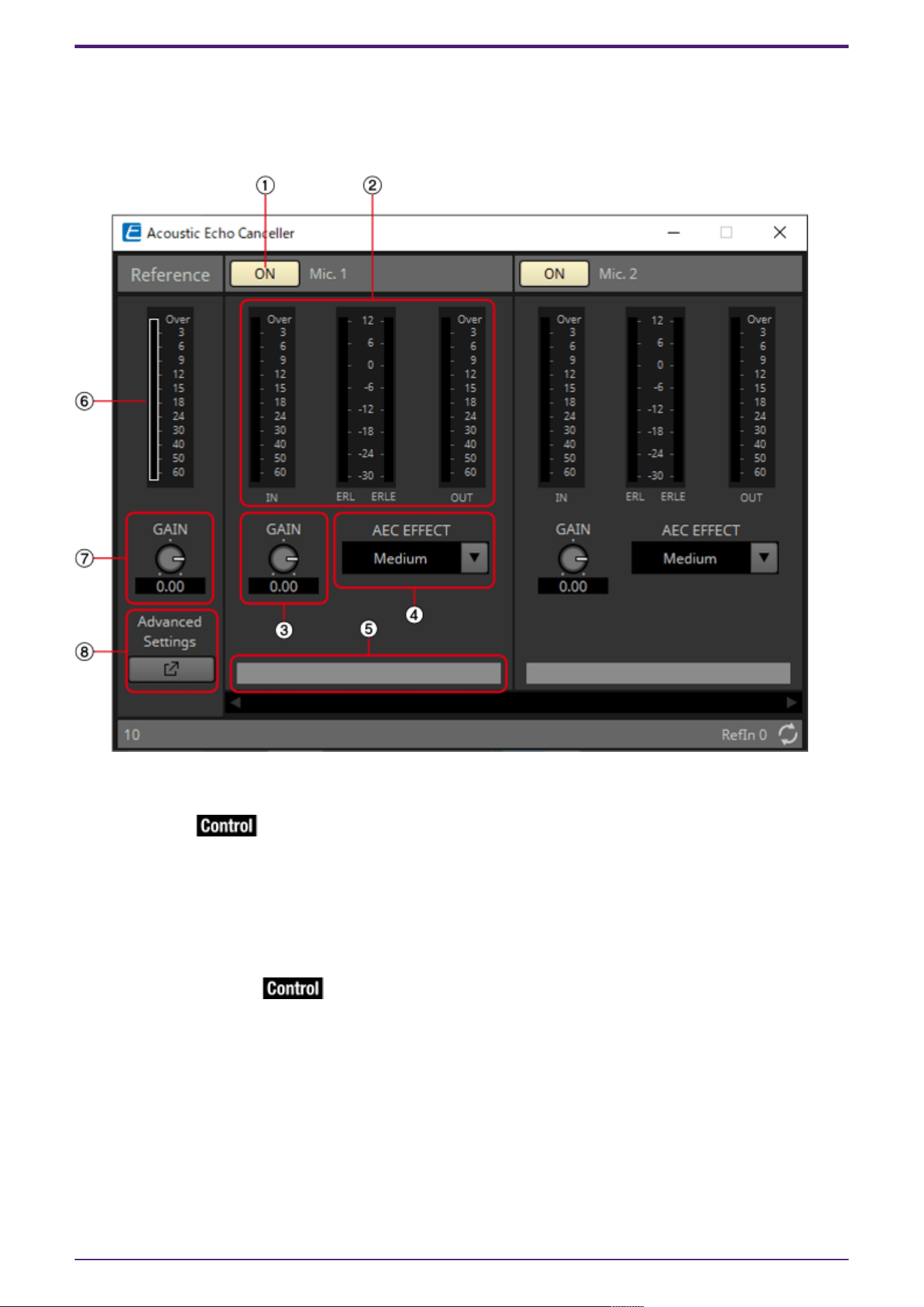
2.3.1. “AEC” component editor
This specifies AEC-related settings. The left side of the screen is Reference, and the right side of the
screen is for settings related to microphones connected to Mic In 1–16. If there are more than five
mics, a scroll bar will be displayed at the bottom.
Mic. 1–16
① [ON] button
Switches between enabling or disabling AEC for each microphone.
② Level meters
These show the input/output levels and information related to acoustic echo.
•
[IN] level meter
Shows the input level from the microphone.
•
[ERL] level meter
Shows in real time the amount of sound (dB) collected by the near end microphone from a remote
location that was originally generated by a near end speaker (audio that is an echo factor). A
range from 0 dB to around –16 dB is a guideline for a good installation environment.
If this meter shows a positive value, the following conditions may be applicable. Please change
so that ERL is a negative number. If it is lower than –16 dB, the microphone’s input level may be
low.
2. Audio Components
8 | ProVisionaire Design Component Guide
・Speaker volume is loud.
・Mic gain (MIC1, MIC2) is high.
・The mic and speaker are positioned close together.
•
[ERLE] level meter
Shows in real time the amount of echo (dB) removed by the AEC. The more negative the ERLE
value becomes, the more echo is removed by the AEC.
•
[OUT] level meter
Shows the output level from the AEC.
③ [GAIN] knob
This sets the mic gain.
④ [AEC EFFECT] type
This sets the AEC effect. There are 4 options: Soft/Medium/Hard/Custom.
• Soft: The amount of echo elimination is decreased, but sound quality improves.
• Medium: This is the initial setting.
• Hard: The amount of echo elimination is increased, but sound quality decreases.
• Custom: The AEC can be manually set on the Advanced Settings window.
Adjust to suit the conditions in the conference room (close location) while checking the audio. Please
use Medium unless specifically necessary otherwise.
By switching the AEC Effect type, multiple parameters for echo canceling, noise reduction, and
reverberation canceling can be switched to the recommended settings simultaneously. When switching
to Custom from a non-Custom setting, the current values for that type will be set in the Advanced
parameters.
⑤ Port text box
Shows the port name. The name can be changed by double clicking. It cannot be changed when AUTO is
set to On.
Reference
⑥ Level meter
Shows the input level from Reference.
⑦ [GAIN] knob
Sets the Reference gain.
⑧ [Advanced Settings] window open button
Shows the Advanced Settings window.
2. Audio Components
ProVisionaire Design Component Guide | 9
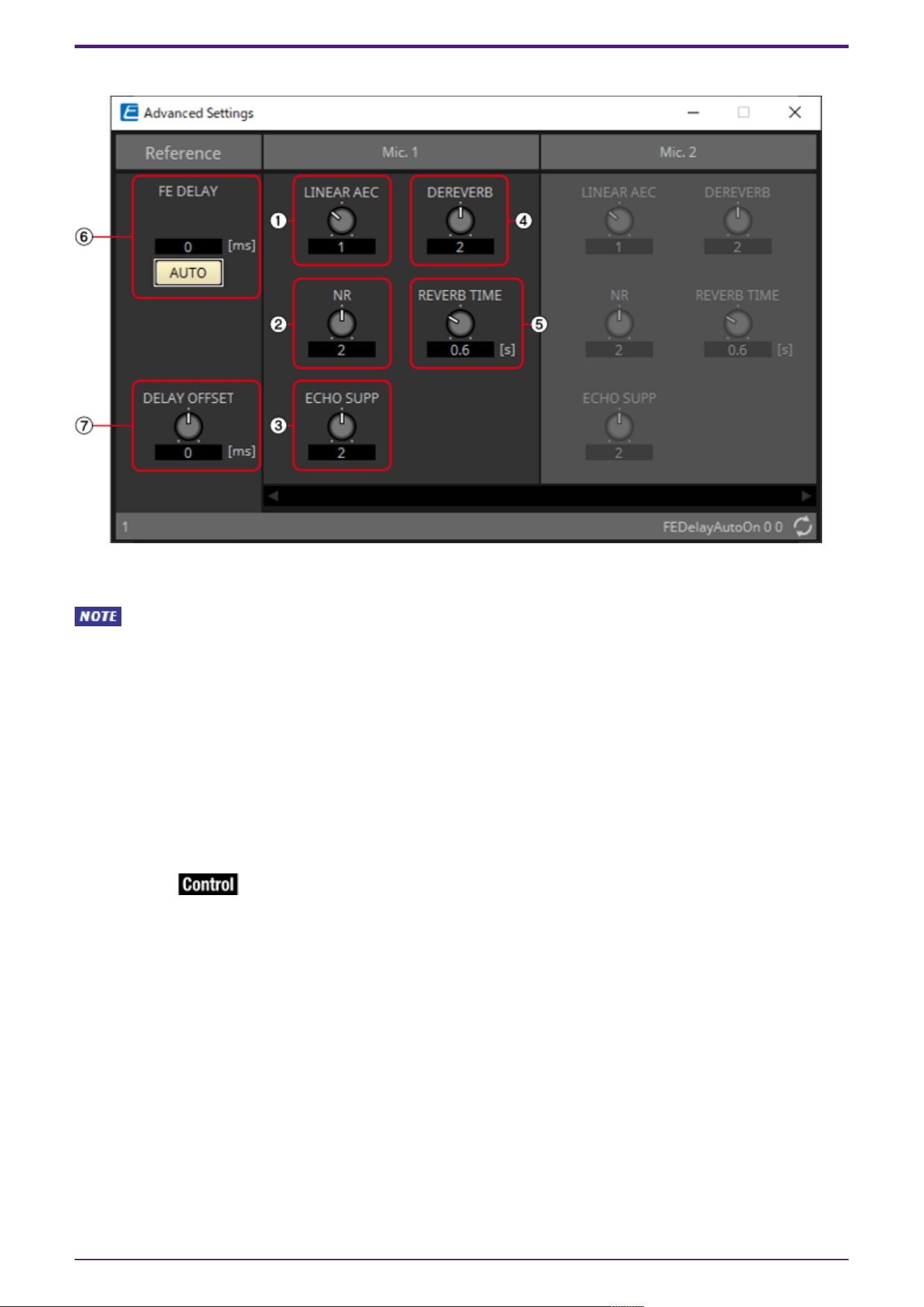
2.3.2. Advanced Settings window
Mic. 1–16
[LINEAR AEC] knob/[ECHO SUPP] knob
These two are echo canceling functions that use different methods. As the numeric value is increased,
more echo cancellation is performed, but if it is raised too high, each one will cause a different type of
negative effect. Therefore, it is necessary to understand their negative effects and maintain a
balance of the two to keep the settings within a necessary and sufficient range.
① [LINEAR AEC] knob
Sets the strength of the echo canceler function. As the strength is increased, more echo cancellation
is performed, but it decreases the double-talk (when near and remote speakers speak at the same
time) performance. (The echo cancellation performance during double-talk is decreased, and the near
speaker’s voice may become inaudible.)
This can only be set when Custom has been selected for [AEC EFFECT].
② [NR] knob
Please set this to a higher value for rooms with a large amount of noise. If the strength is raised too
high, the necessary signals will also be removed, which will decrease the sound quality of the speaking
voices. Please set to the lowest necessary strength.
This can only be set when Custom has been selected for [AEC EFFECT].
③ [ECHO SUPP] knob
Sets the strength of the echo canceler function. As the strength is increased, more echo cancellation
is performed, but if the strength is raised too high, the necessary signals will also be removed, which
will decrease the sound quality of the speaking voices.
This can only be set when Custom has been selected for [AEC EFFECT].
④ [DEREVERB] knob
Sets the strength of the dereverberation function, which removes the reverberation generated in
closed rooms. Please set this to a higher value for rooms with a large amount of reverberation. If the
strength is raised too high, the necessary signals will also be removed, which will decrease the sound
quality of the speaking voices. Setting to the lowest necessary strength is recommended.
2. Audio Components
10 | ProVisionaire Design Component Guide
Reverberation is not removed when set to 0. Best used with "DEREVERB" set to Off (0) for rooms with
almost no reverberation.
This can only be set when Custom has been selected for [AEC EFFECT].
⑤ [REVERB TIME] knob
Sets the reverberation time inside a room. Normally, no change from the Default value of 0.6 s is
necessary. When using the AEC in a glass room or other location that has more reverberation than a
normal conference room, adjust to increase the target REVERB TIME to 0.6–1.0 s. For events in large
halls, please set the reverb time to suit the hall’s reverberation time.
This can only be set when Custom has been selected for [AEC EFFECT].
Reference
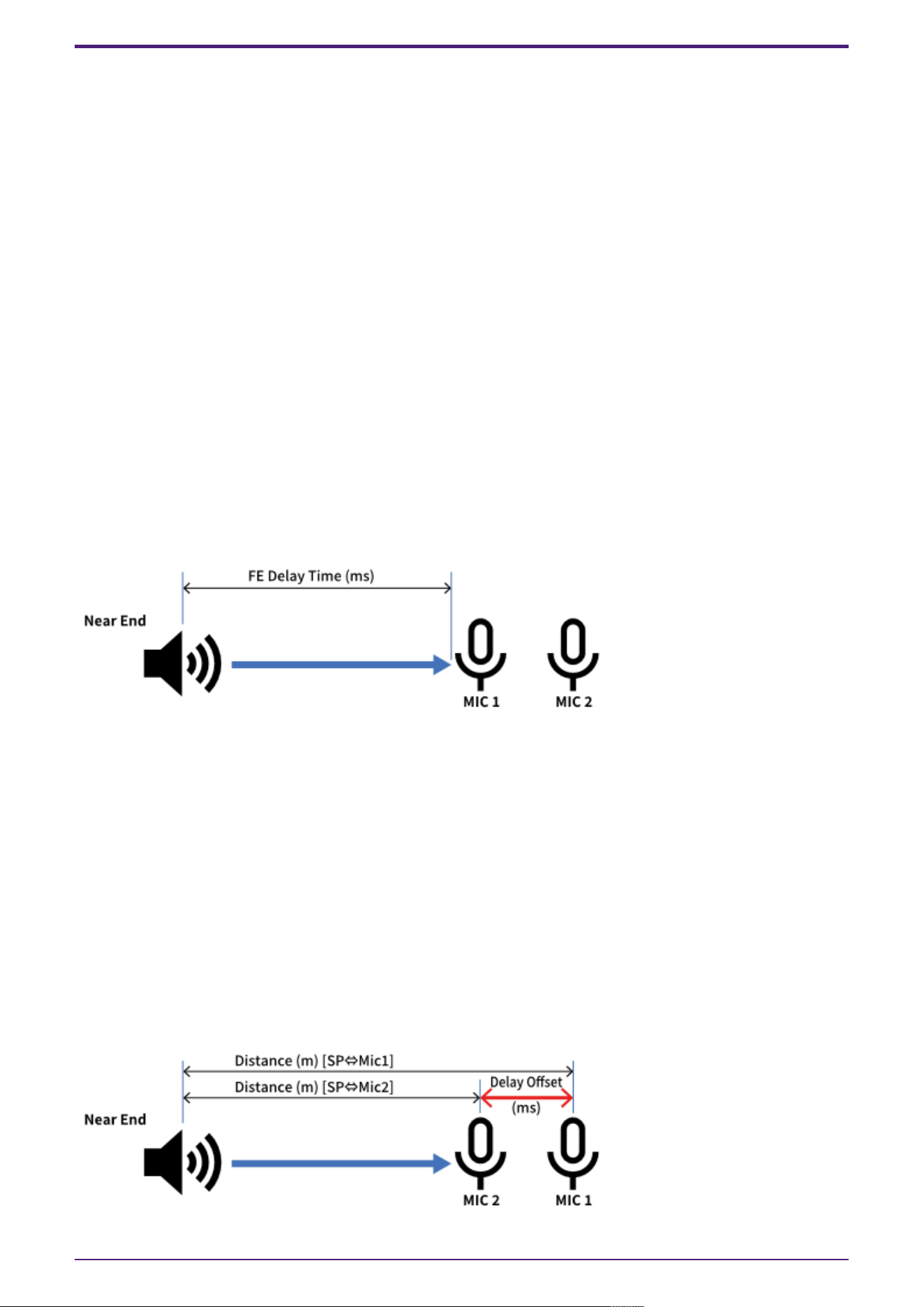
⑥ [FE DELAY] knob
Sets the delay time between the speakers and MIC1 by comparing the audio output from the speakers
and the audio picked up by the microphone. This is normally used in AUTO.
When AUTO is turned Off, the knob will be shown.
How to manually set FE (Far End) Delay
1. Please place the microphone connected to MIC1 at the closest position to the speakers sending
sound from the far area.
2. The FE Delay value is calculated based on the position of the microphone connected to MIC1.
⑦ [DELAY OFFSET] knob
The calculation of the FE Delay value is based on the position of the microphone connected to MIC1. If
the microphone connected to MIC1 is placed at the closest position to the speaker, as recommended, it
will not be necessary to implement a Delay Offset. If the microphone connected to MIC1 cannot be
placed at the closest position to the speaker, the FE Delay will be set appropriately by setting the
Delay Offset.
How to set Delay Offset
1. Measure the distance to the microphone connected to MIC1.
2. Measure the distance to the microphone placed closest to the speaker (MIC2 in this case).
3. Calculate the difference between those 2 distances, and use the time information converted
into a value using the formula below as the value to input into the Delay Offset.
Time (msec) = Distance (m) ÷ 340 (m/s) × 1,000 (Speed of sound defined as 340 m/s)
2. Audio Components
ProVisionaire Design Component Guide | 11
2.3.3. Control
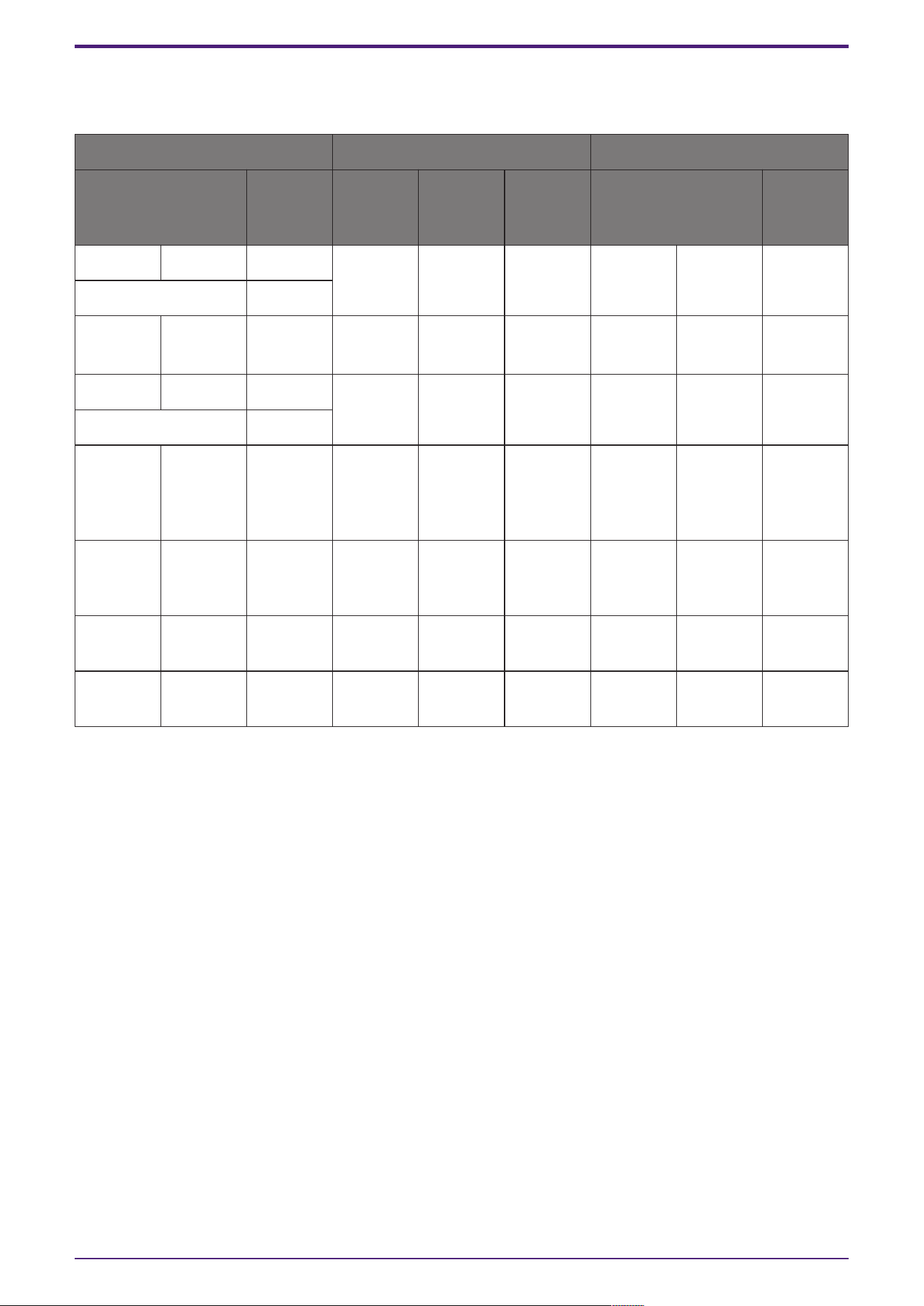
Parameter types of the input/output values for each Port
Input Value Control Parameter Output Value
Type Range Input
Port
Name
Paramete
r Range
Output
Port
Name
Type Range
Value dB −∞–10.00 ● Ref
Gain
−∞–10.00 ● Ref
Gain
Value dB −∞–10.00
Normalized 0.00–1.00
Value Num 0,1 ● Mic On
Mic1
OFF:0,
ON:1
● Mic On
Mic1
Value Num 0,1
Value dB −∞–10.00 ● Mic
Gain Mic1
−∞–10.00 ● Mic
Gain Mic1
Value dB −∞–10.00
Normalized 0.00–1.00
Value Num 0,1,2,3 ● Mic
Effect
Mic1
Soft:0
Midium:1
Hard:2
Custm:3
● Mic
Effect
Mic1
Value Num 0,1,2,3
Value Num 0,1,2,3,4 ● Mic NR
Mic1
0:0, 1:1,
2:2, 3:3,
4:4
● Mic NR
Mic1
Value Num 0,1,2,3,4
- - - - −∞–10.00 ● ERL
Mic1
Value dB −∞–10.00
- - - - −∞–10.00 ● ERLE
Mic1
Value dB −∞–10.00
2. Audio Components
12 | ProVisionaire Design Component Guide
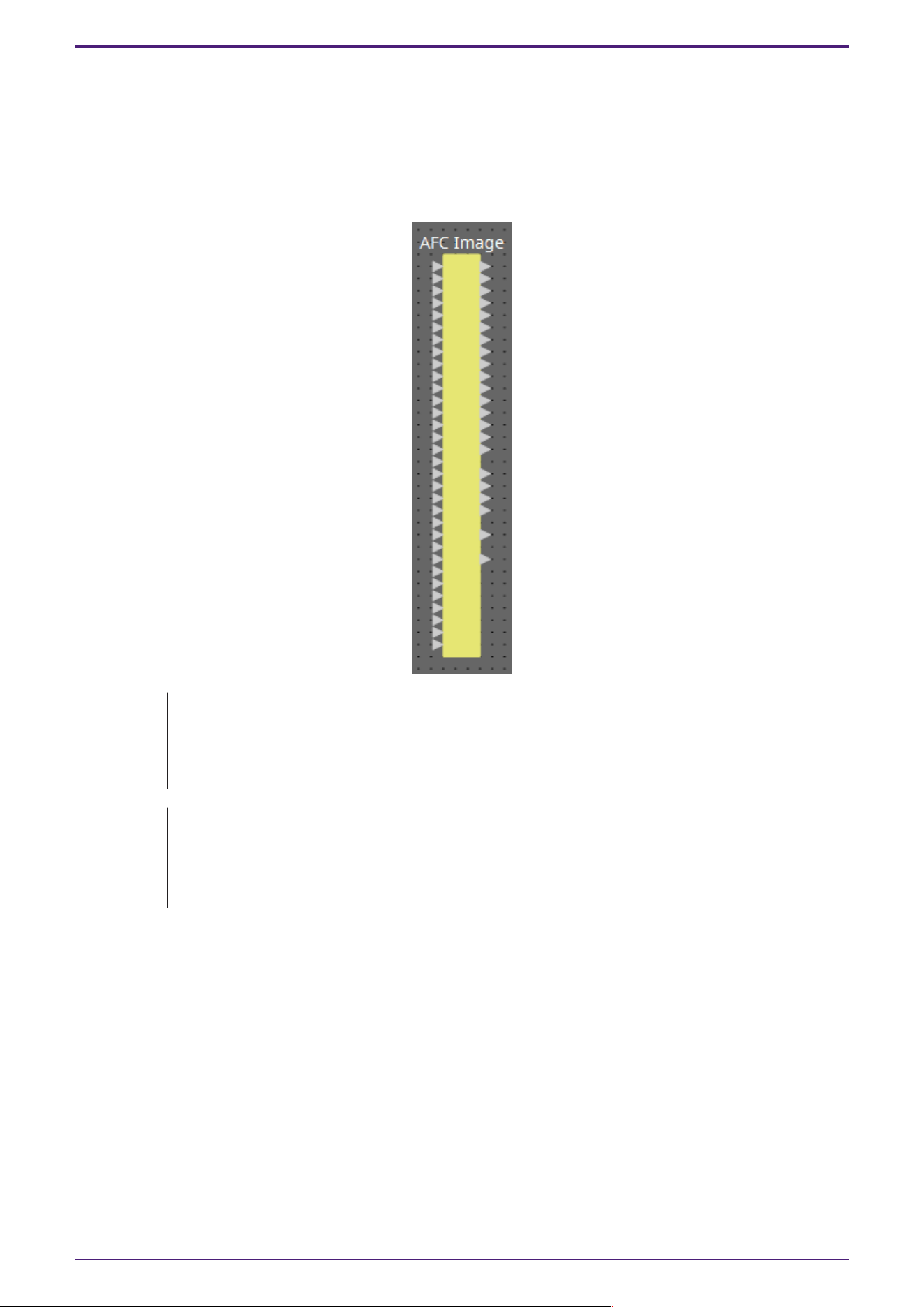
2.4. AFC Image
AFC Image is an object-based sound image control component that creates the immersive sound
environment you envision in any space.
By freely controlling up to 128 (DME10) or 64 (DME7) input channels in three dimensions using an
object-based method, you can create immersive sound effects with appropriate localization and
movement of sound images for a variety of applications and spaces.
The parameters of the AFC Image components cannot be controlled in the
ProVisionaire Design component editors.
To control them, use the AFC Image Controller.For details, refer to the AFC Image
Controller User Guide.
A separate license is required to operate the AFC Image component with the DME7.
The DME10 can operate 32In/16Out AFC Image components without requiring any
additional licenses.
For details, refer to the AFC Image Controller User Guide.
2. Audio Components
ProVisionaire Design Component Guide | 13
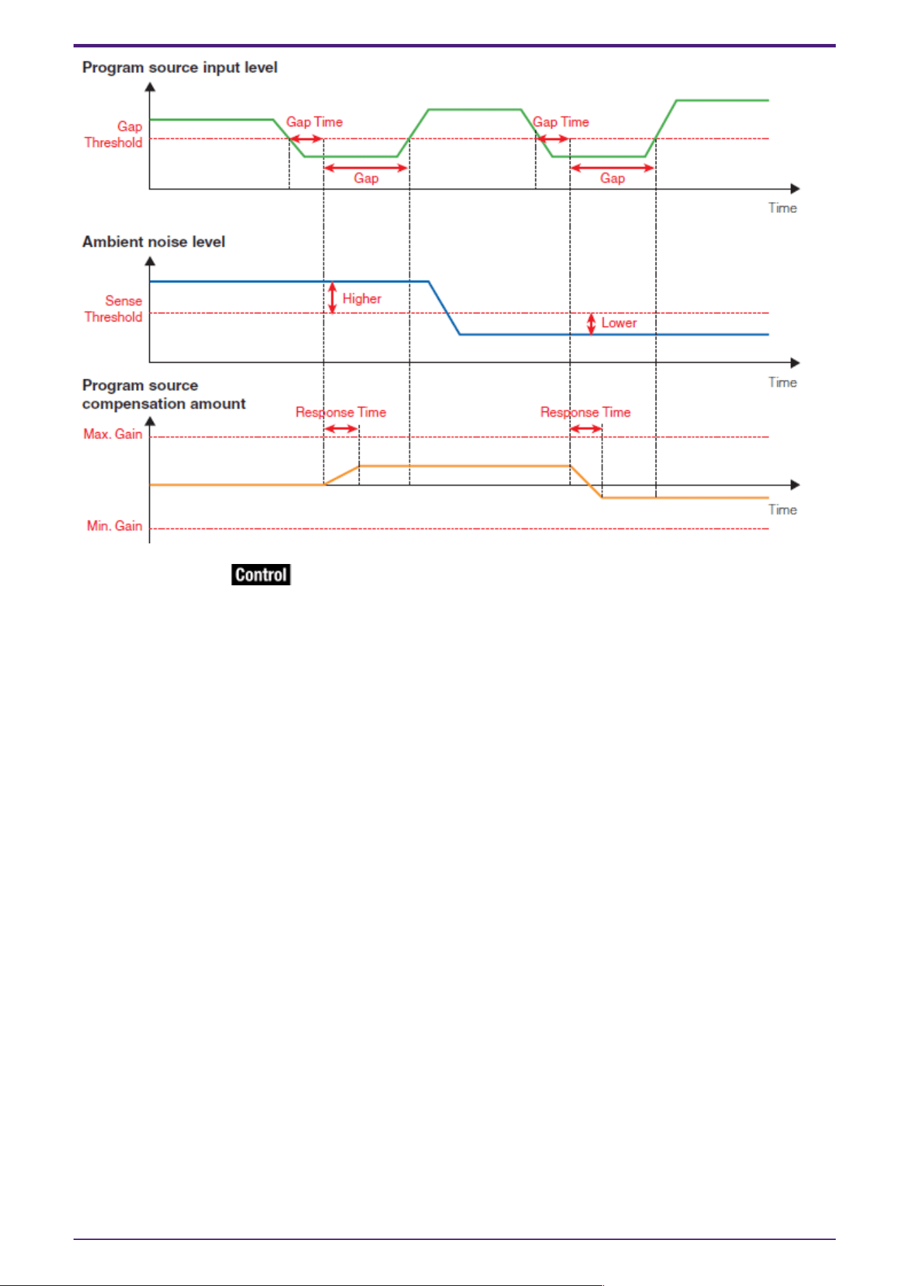
2.5. Ambient Noise Compensator (ANC)
ANC (Ambient Noise Compensator) is a function that boosts or attenuates the level of the program
source according to the level that is being input via an ambient noise detection mic. The ANC function
provided by the DME is a gap-type ANC that detects silent intervals such as between songs, detects
the noise level during those intervals, and varies the level accordingly.
When placing this in the design sheet, select either Mono, Stereo or Multi as appropriate for the
program source. The illustrations used in the following explanation are for the case of Stereo. Place
the ambient noise detection mic in a location where it will not receive direct sound from the speakers
but will be close to the source of the ambient noise, such as on the ceiling in the middle of the room
above the crowd or audience, and at a distance from the speakers.
Examples of use
Example 1: In a location where a speech is being given, automatically adjust the output level of the
program source up or down according to the level of ambient noise (e.g., crowd noise).
Example 2: In a restaurant, adjust the background music (program source) according to the noise of
the surrounding conversation in order to maintain privacy.
Connect the signal from the ambient noise detection mic to the bottom input.
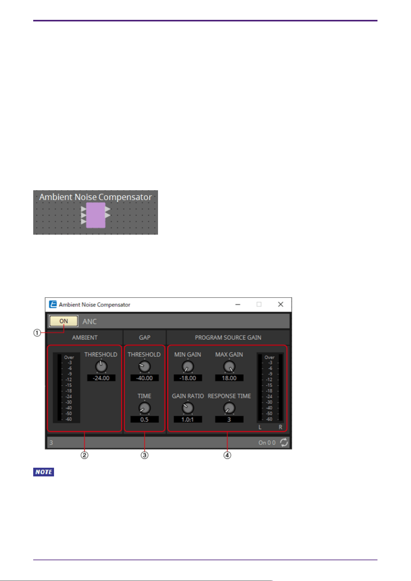
2.5.1. ”Ambient Noise Compensator” component editor
Here you can make settings related to ANC.
When Multi is selected, the ④ meter is not displayed. Please use the separate Meter component.
2. Audio Components
14 | ProVisionaire Design Component Guide
① ANC [ON] button
Switches the ANC function between enabled and disabled.
② AMIBIENT
•
Level meter
Shows the level of ambient noise.
•
[THRESHOLD] knob
Specifies the average level of ambient noise. If the level of ambient noise exceeds this value, the
level of the program source is raised; if the level is lower than this value, the level of the
program source is lowered.
③ GAP
•
[THRESHOLD] knob
Specifies the threshold value of the program source.
If the level of the program source remains below the threshold for a specified time, it will be
interpreted as a gap.
•
[TIME] knob
Specifies the time required for a gap to be detected.
④ PROGRAM SOURCE GAIN
•
[MIN GAIN] knob
Specifies the minimum value of program source level compensation.
•
[MAX GAIN] knob
Specifies the maximum value of program source level compensation.
•
[GAIN RATIO] knob
Specifies the ratio of program source level compensation. This is specified as the ratio “Program
source compensation amount”: “Amount of ambient noise increase from the threshold value.”
2. Audio Components
ProVisionaire Design Component Guide | 15
•
[RESPONSE TIME] knob
Specifies the response speed for level compensation.
•
Level meter
Indicates the output level of the program source after compensation.
2.5.2. Control
Parameter types of the input/output values for each Port
Input Value Control Parameter Output Value
Type Range Input
Port
Name
Paramete
r Range
Output
Port
Name
Type Range
Value Num 0,1 ● On
OFF:0,
ON:1
● On Value Num 0,1
2. Audio Components
16 | ProVisionaire Design Component Guide
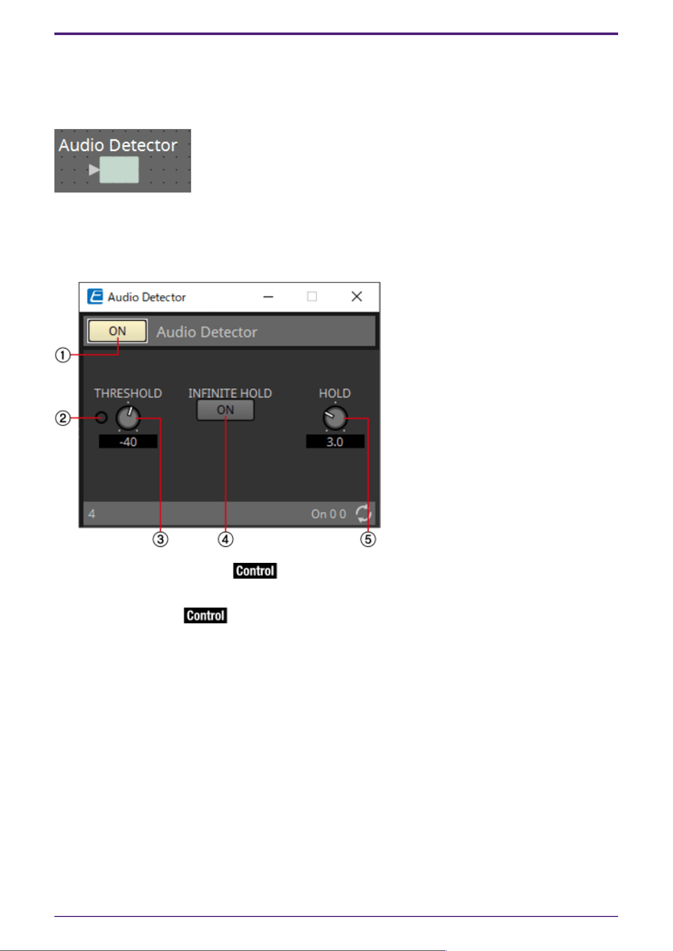
2.6. Audio Detector
Audio Detector is a function that detects audio signals. By registering the detection indicator to the
GPI Output, a signal can be output from the unit’s GPI [OUT] connector when an audio signal is
detected.
2.6.1. ”Audio Detector” component editor
Here you can specify the threshold value of the audio signal, and see whether an input exceeding the
threshold value has been detected.
① Audio Detector [ON] button
Switches the Audio Detector function between enabled and disabled.
② Detection indicator
Lights when an input exceeding the threshold value is detected. If this is registered to an GPI Output
or Remote Control Setup List, the lit status of the detection indicator can be viewed on the external
device.
③ [THRESHOLD] knob
Specifies the threshold value at which an audio signal is detected.
④ [INFINITE HOLD] button
If this is on, the detection indicator remains lit once an audio signal is detected. If this is off, the
detection indicator lights when audio is detected, and when the audio signal falls below the threshold
value, the detection indicator goes dark after the time specified by the [HOLD] knob has elapsed.
⑤ [HOLD] knob
If the [INFINITE HOLD] button is off, this specifies the time that the detection indicator remains lit
after the audio signal falls below the threshold value.
2. Audio Components
ProVisionaire Design Component Guide | 17

2.6.2. Control
Parameter types of the input/output values for each Port
Input Value Control Parameter Output Value
Type Range Input
Port
Name
Paramete
r Range
Output
Port
Name
Type Range
Value Num 0,1 ● On
OFF:0,
ON:1
● On Value Num 0,1
- - - ●
Detection
Indicator
OFF:0,
ON:1
●
Detection
Indicator
Value Num 0,1
2. Audio Components
18 | ProVisionaire Design Component Guide
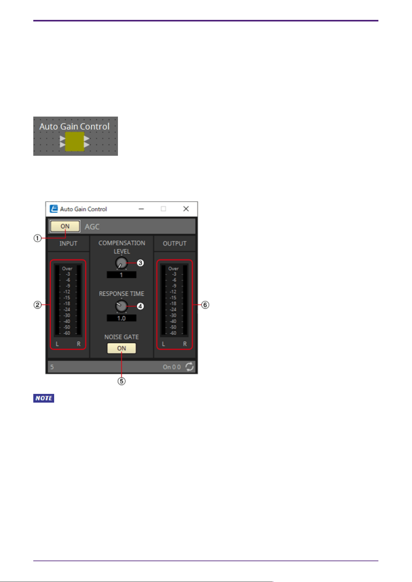
2.7. Auto Gain Control (AGC)
AGC (Auto Gain Controller) is a function that automatically compensates the gain according to the
input level, keeping a constant output level for an incoming signal whose level is changing. For
example, differences in how closely and how loudly a person is speaking into a mic can make their
amplified voice vary in volume, making it less intelligible. In such cases, the volume will be
automatically adjusted within a fixed range.
When placing this in the design sheet, select either Mono, Stereo or Multi. The illustrations used in the
following explanation are for the case of Stereo.
2.7.1. ”Auto Gain Control” component editor
Here you can make settings related to AGC.
When Multi is selected, the meter is not displayed. Please use the separate Meter component.
2. Audio Components
ProVisionaire Design Component Guide | 19
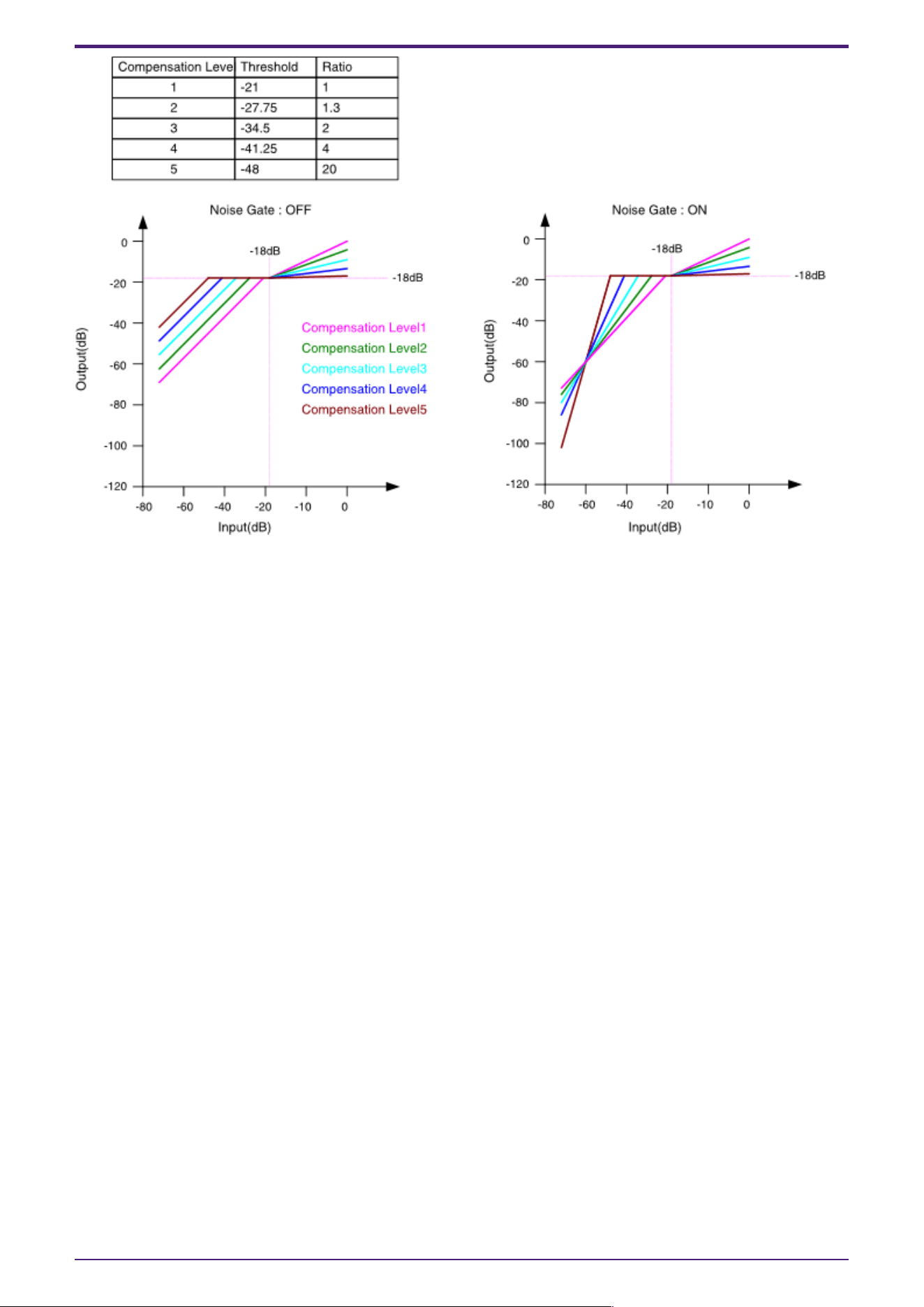
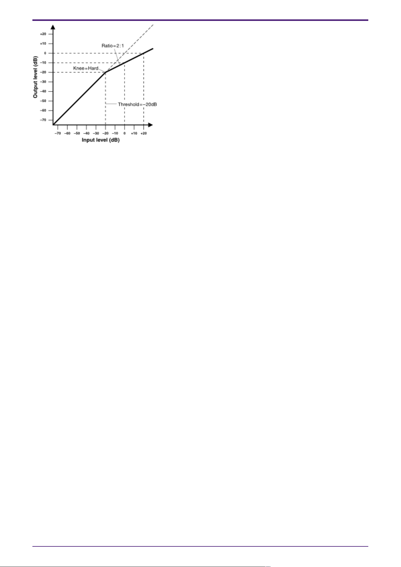
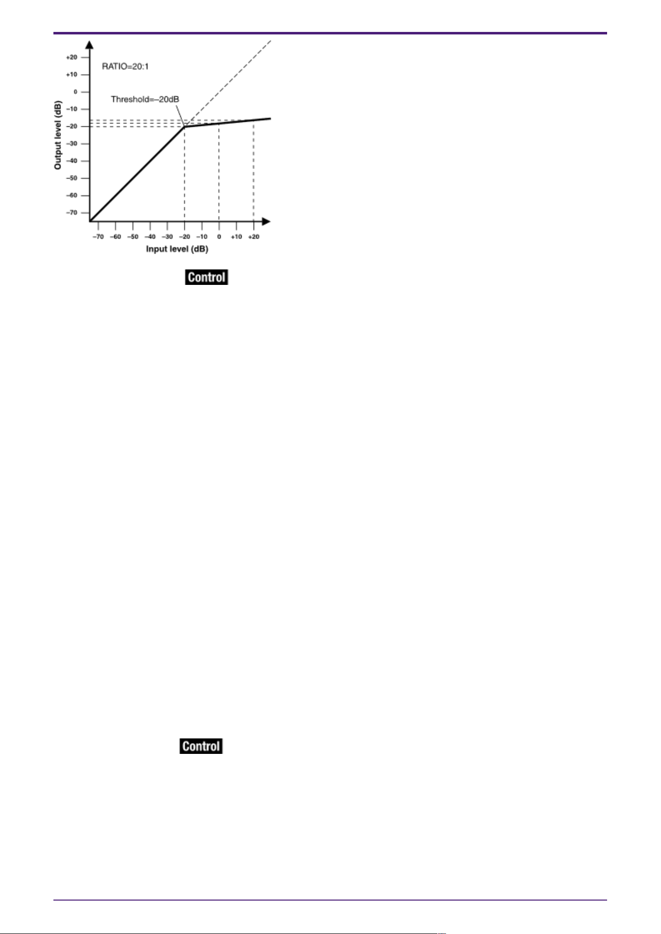
If the input is above the Threshold value and below –18 dB, the output is set to –18 dB. If the input is
above the Threshold value and above –18 dB, the output level is adjusted by the Ratio value.
If the noise gate is on, the volume is adjusted so that input and output are the same level at –60 dB,
and then adjusted so that the output is –18 dB when it reaches the Threshold value.
If the input is above the Threshold value and below –18 dB, the output is set to –18 dB.
If the input is above the Threshold value and above –18 dB, the output level is adjusted by the Ratio
value.
① AGC [ON] button
Switches the AGC function between enabled and disabled.
② [INPUT] level meter
Shows the input signal level.
③ [COMPENSATION LEVEL] knob
Specifies the amount of gain compensation. Higher settings will produce more compensation. Please
note that it might not be possible to maintain a constant output level if this value is changed
suddenly.
④ [RESPONSE TIME] knob
Specifies the response speed for gain compensation. This applies to compensation that raises the gain;
it is the time required for a 6 dB increase. It does not affect compensation that lowers the gain.
⑤ NOISE GATE [ON] button
Switches the noise gate between enabled and disabled.
⑥ [OUTPUT] level meter
Shows the compensated output signal level.
2. Audio Components
20 | ProVisionaire Design Component Guide

2.7.2. Control
There are no parameters that can be controlled through the Control layer.
2. Audio Components
ProVisionaire Design Component Guide | 21
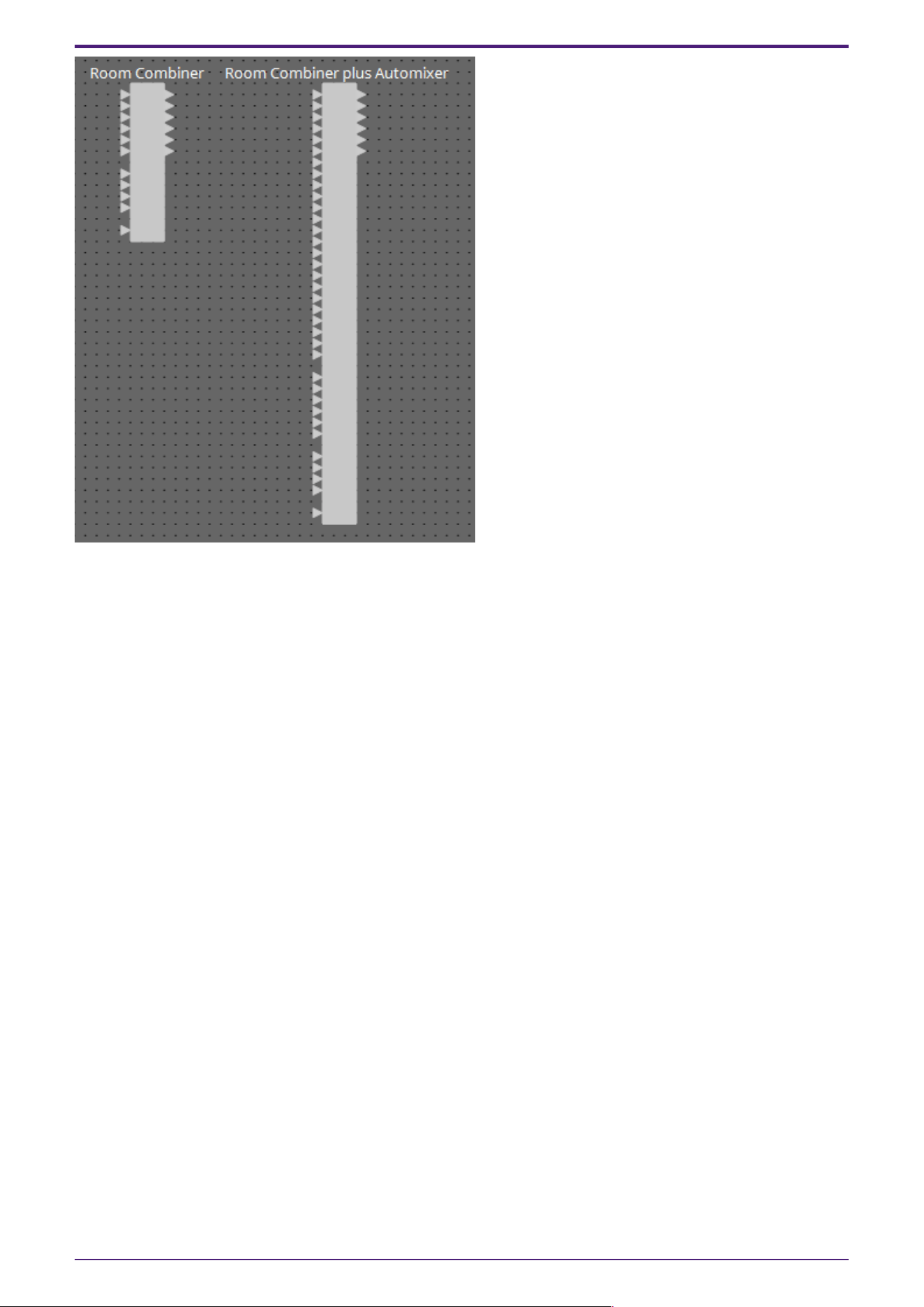
2.8. Combiner: Room Combiner, Room Combiner plus Automixer
This function is used when audio signals are shared between multiple rooms, or when a single room is
partitioned in varying ways. The audio signal outputs are changed according to how the rooms are
divided or connected. The DME provides two types of combiner: “Room Combiner” and “Room Combiner
plus Automixer.” The latter adds Dan Dugan Automixer functionality. Up to eight rooms can be
registered in the combiner, and you can also specify the shape of the rooms as their actual shape. You
can register snapshots in a remote controller such as a DCP, and recall parameters as appropriate for
the state of the rooms.
Here we explain using “Room Combiner plus Automixer.”
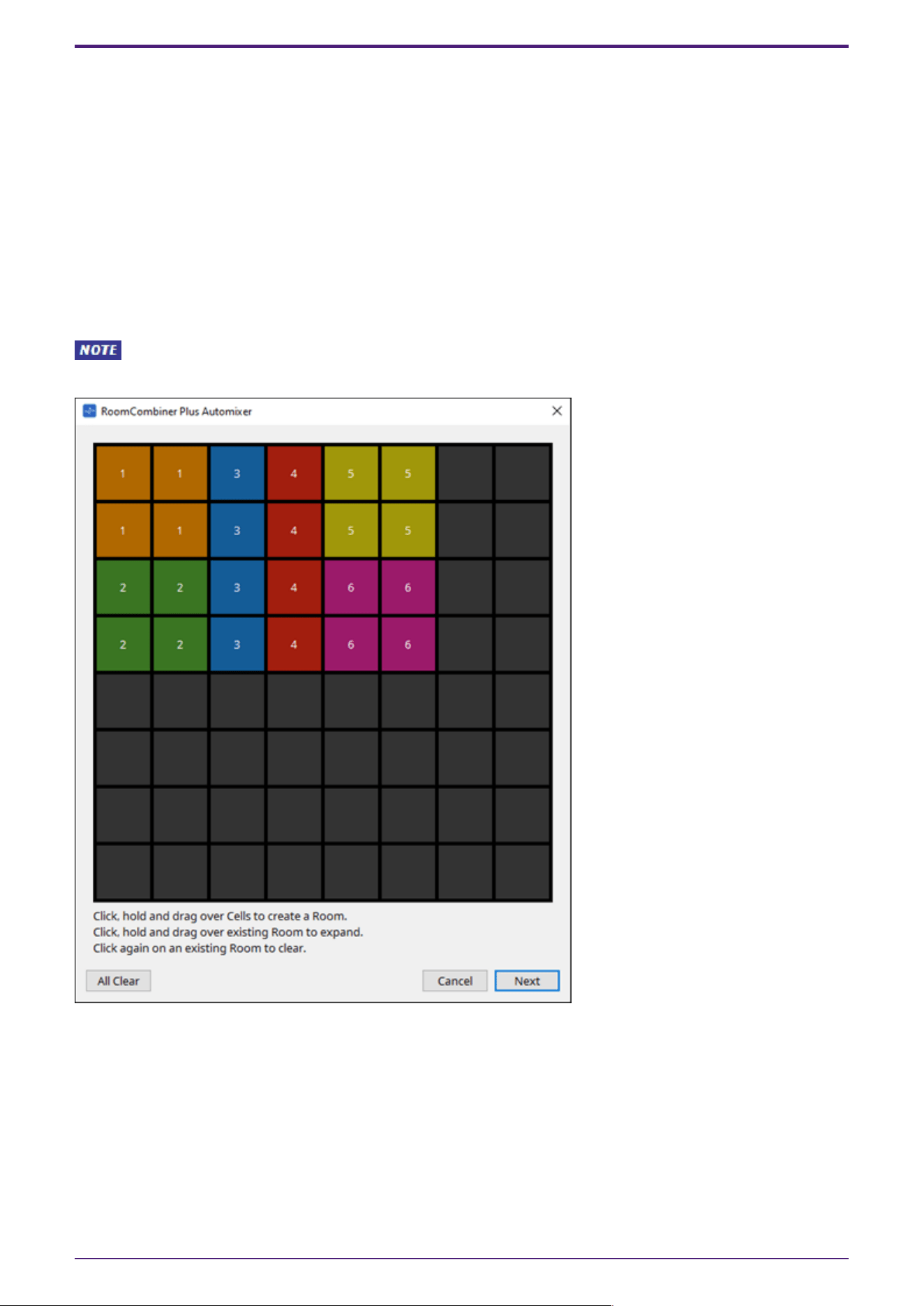
When you drag this from the “Components” area and drop it on the design sheet, a dialog box appears,
allowing you to design the room.
After the Combiner components have been placed, the number of rooms and number of MICs
cannot be changed from Properties.
Drag the cells to create the room. When you click a cell that makes up a room, the room is canceled;
when you drag from a cell that makes up a room to a cell that is not part of a room, the room is
extended. Create the rooms, and then click the [Next] button. The screen changes to a screen where
you can reassign the room numbers.
2. Audio Components
22 | ProVisionaire Design Component Guide
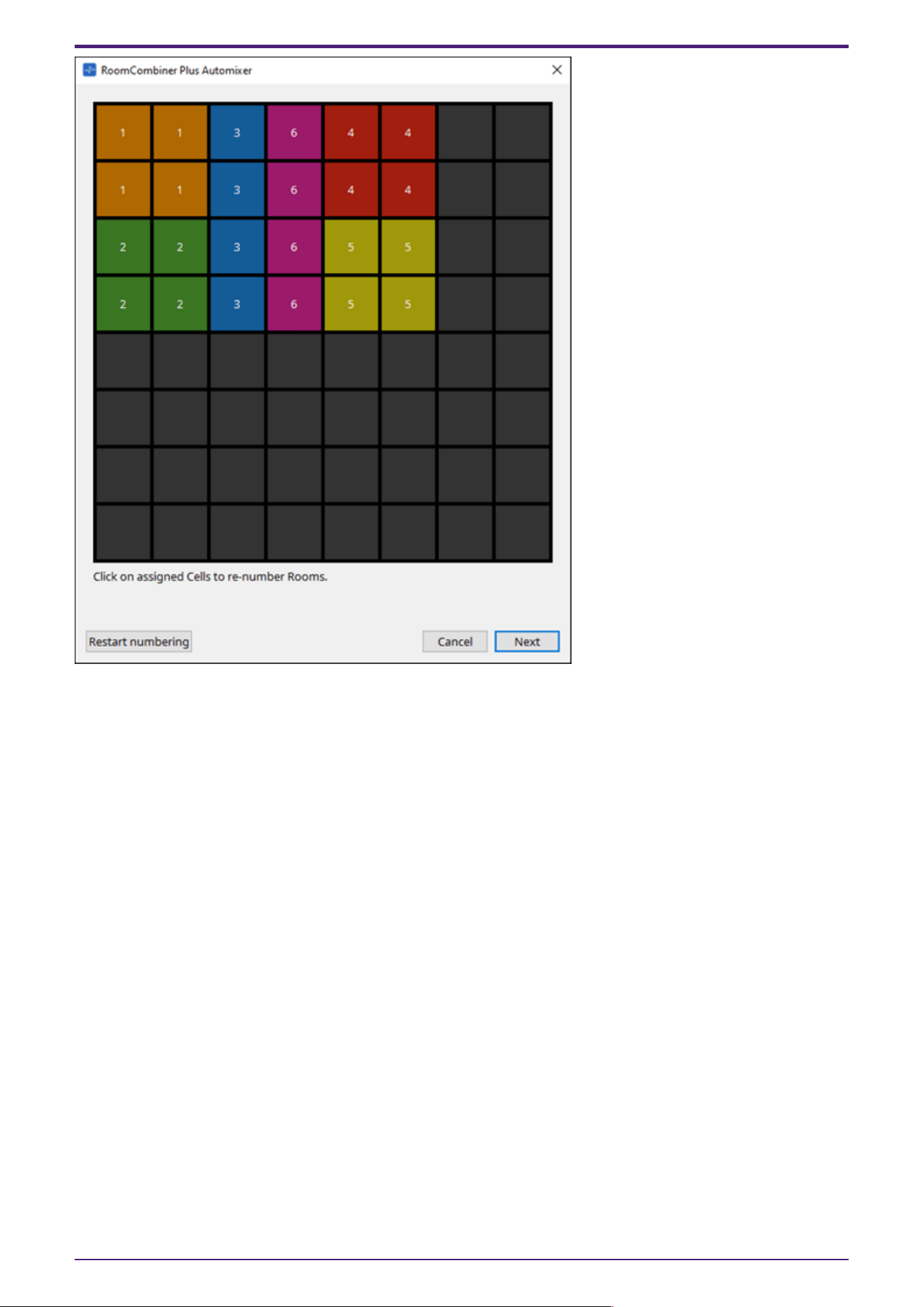
If you want to reassign the room numbers, click the room numbers consecutively. During editing, if you
want to renumber the rooms starting from 1, click the [Restart numbering] button.
After you have finished renumbering, click the [Next] button. The screen changes to a screen where
you can specify the number of mics placed in the rooms.
2. Audio Components
ProVisionaire Design Component Guide | 23
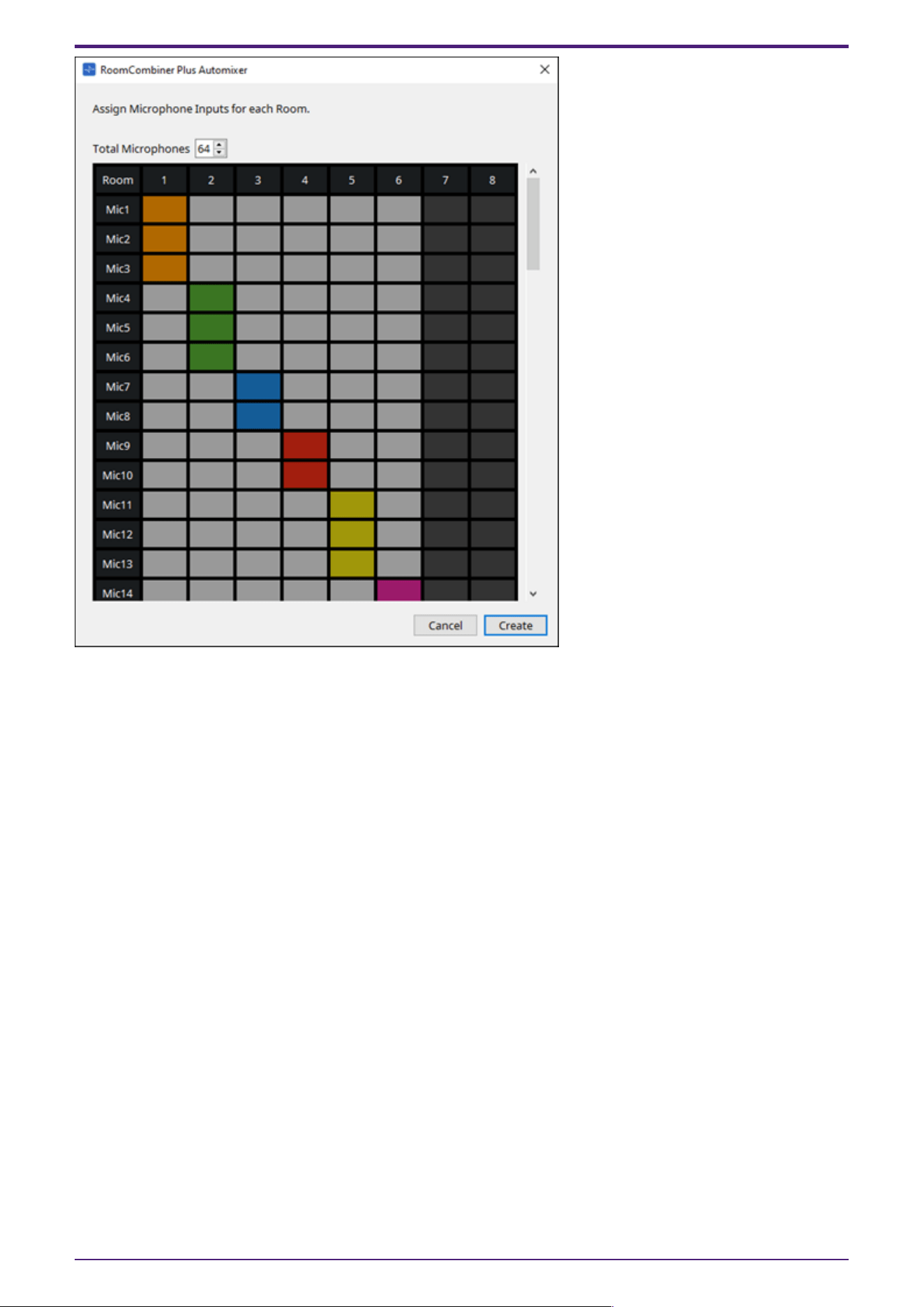
In the dropdown list, select the number of mics used by all rooms, and click or drag the cells of the
mics to be assigned to the rooms.
After you have finished making assignments, click the [Create] button. “Room Combiner plus
Automixer” is placed in the design sheet. “Room Combiner” does not have this screen.
2. Audio Components
24 | ProVisionaire Design Component Guide
The inputs are assigned as follows, starting from the top.
•
Room Combiner
Room In (pre-mixed sound or individual mics) x number of rooms
BGM In × 4
Paging (broadcast to all rooms) x 1
•
Room Combiner plus Automixer
In (inputs sent through Automixer) x number of mics (maximum 64 mics)
Local In (inputs not sent through Automixer) x number of rooms
BGM In × 4
Paging (broadcast to all rooms) x 1
2. Audio Components
ProVisionaire Design Component Guide | 25
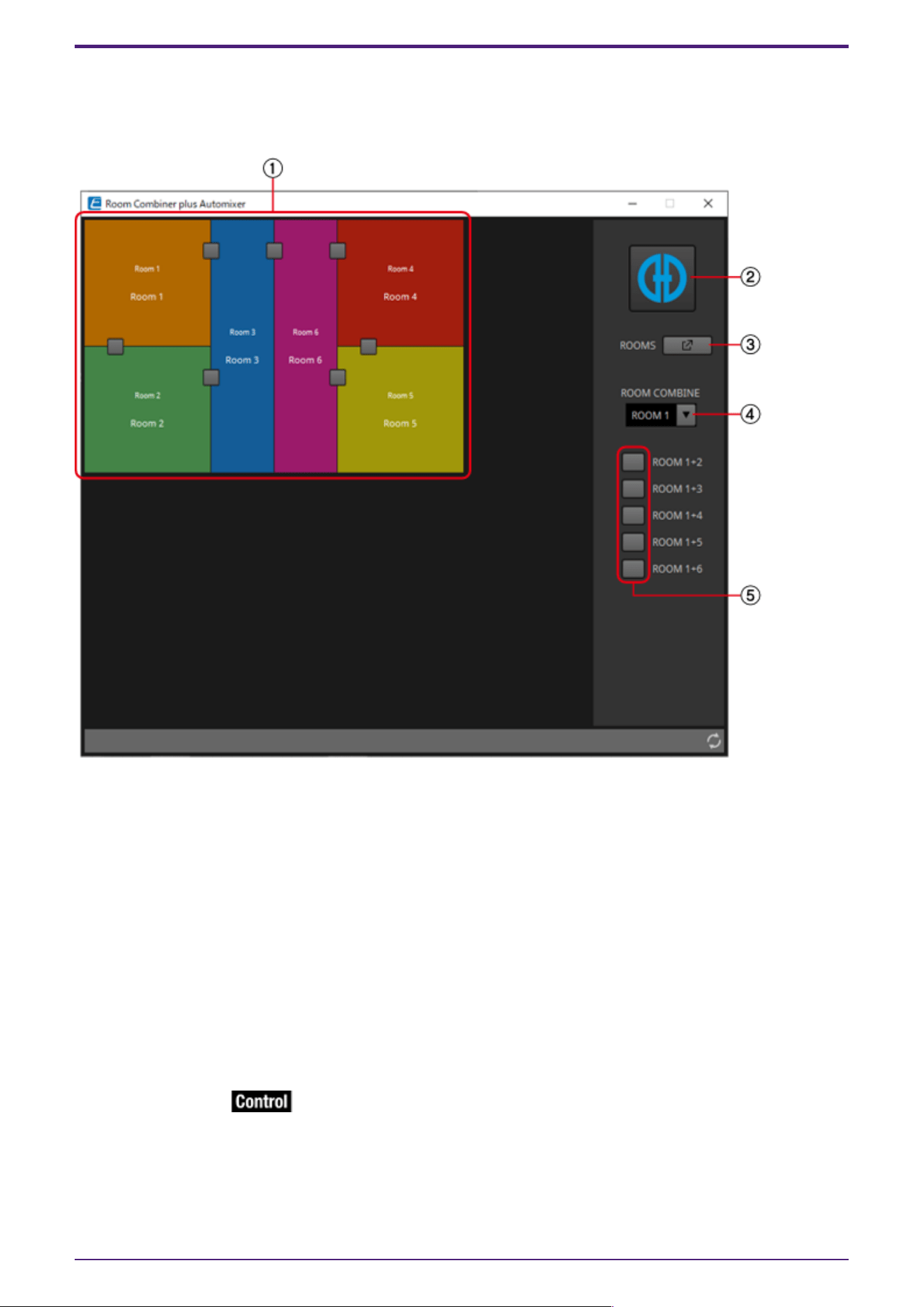
2.8.1. “Room Combiner” component editor/”Room Combiner plus Automixer”
component editor
Here you can specify which rooms are combined.
① Rooms
This area shows the rooms. When you click a button located between two rooms (the combine button),
the rooms are combined. Combined rooms are shown in the same color. When you double-click or right-
click a tile and choose [Open Parameter
Window], the combiner parameter setting window appears.
② [Dugan Automixer] button (only for Room Combiner plus Automixer)
When you click this, the Dugan Automixer window for Room Combiner plus Automixer appears.
③ [ROOMS] button
Click this to open the combiner parameter setting window.
④ Room selection dropdown list
This selects the room to which the combine buttons shown below are assigned.
⑤ Combine buttons
These specify which rooms are combined. Non-adjacent rooms can also be combined.
2. Audio Components
26 | ProVisionaire Design Component Guide
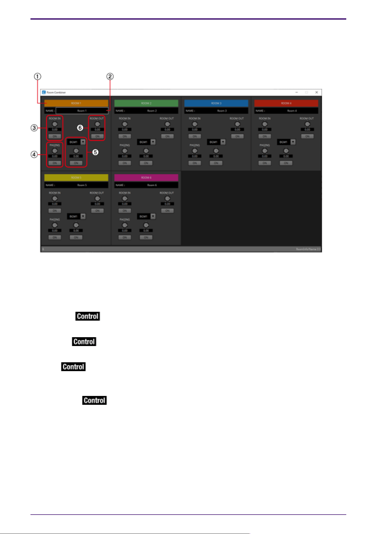
2.8.2. Combiner parameter setting window (Room Combiner)
Here you can view and edit the parameters of all rooms.
When rooms are connected, [ROOM IN] can be adjusted for each room; however, the setting of the
lowest-numbered room takes priority for [PAGING]/[BGM]/[ROOM OUT].
① Index
Shows the number and color assigned to the room. Connected rooms are shown in the same color.
② [NAME] boxx
Indicates the room name. You can double-click the name and edit it.
③ [ROOM IN]
Adjusts the send amount from ROOM IN to ROOM OUT, and turns mute on/off.
④ [PAGING]
Adjusts the send amount from PAGING to Room OUT, and turns mute on/off.
⑤ [BGM]
Selects one of BGM1 to 4, adjusts the amount of that BGM that is sent to ROOM OUT, and turns mute
on/off.
⑥ [ROOM OUT]
Adjusts the ROOM OUT level and turns mute on/off.
2. Audio Components
ProVisionaire Design Component Guide | 27
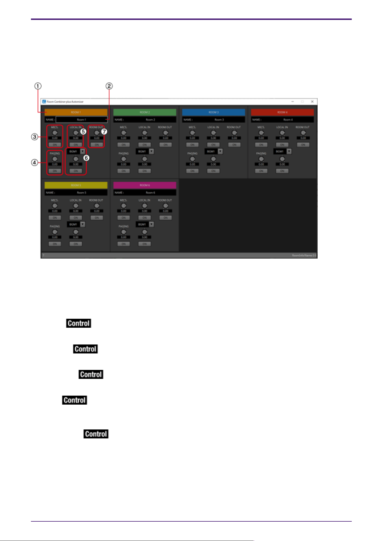
2.8.3. Combiner parameter setting window (Room Combiner plus Automixer)
This mixes [LOCAL IN], [BGM], and [PAGING] with each room’s mic inputs that have been auto-mixed
and output by the Dugan Automixer. Here you can view and edit the parameters of all rooms.
When rooms are connected, [LOCAL IN] can be adjusted for each room; however, the setting of the
lowest-numbered room takes priority for parameters other than [LOCAL IN].
① Index
Shows the number and color assigned to the room. Connected rooms are shown in the same color.
② [NAME] box
Indicates the room name. You can double-click the name and edit it.
③ [MICS.]
Adjusts the send amount from the Dugan Automixer to ROOM OUT, and turns mute on/off.
④ [PAGING]
Adjusts the send amount from PAGING to ROOM OUT, and turns mute on/off.
⑤ [LOCAL IN]
Adjusts the send amount from LOCAL IN to ROOM OUT, and turns mute on/off.
⑥ [BGM]
Selects one of BGM1 to 4, adjusts the amount of that BGM that is sent to Room Out, and turns mute
on/off.
⑦ [ROOM OUT]
Adjusts the ROOM OUT level and turns mute on/off.
2. Audio Components
28 | ProVisionaire Design Component Guide
2.8.4. Control (Room Combiner)
Parameter types of the input/output values for each Port
Input Value Control Parameter Output Value
Type Range Input
Port
Name
Paramete
r Range
Output
Port
Name
Type Range
Value Num 0,1 ●
Combine
1+2
OFF:0,
ON:1
●
Combine
1+2
Value Num
OFF:0,
ON:1
Value dB −∞–10.00 ● RoomIn
Level
Room1
−∞–10.00 ● RoomIn
Level
Room1
Value dB −∞–10.00
Normalized 0.00–1.00
Value Num 0,1 ● RoomIn
On Room1
OFF:0,
ON:1
● RoomIn
On Room1
Value Num
OFF:0,
ON:1
Value dB −∞–10.00 ● Paging
Level
Room1
−∞–10.00 ● Paging
Level
Room1
Value dB −∞–10.00
Normalized 0.00–1.00
Value Num 0,1 ● Paging
On Room1
OFF:0,
ON:1
● Paging
On Room1
Value Num
OFF:0,
ON:1
Value Num 0,1,2,3 ● BGM
Room1
0:BGM1,1
:BGM2,2:
BGM3,3:B
GM4
● BGM
Room1
Value Num BGM1:0
BGM2:1
BGM3:2
BGM4:3
Value dB −∞–10.00 ● BGM
Level
Room1
−∞–10.00 ● BGM
Level
Room1
Value dB −∞–10.00
Normalized 0.00–1.00
Value Num 0,1 ● BGM
On Room1
OFF:0,
ON:1
● BGM
On Room1
Value Num
OFF:0,
ON:1
Value dB −∞–10.00 ●
RoomOut
Level
Room1
−∞–10.00 ●
RoomOut
Level
Room1
Value dB −∞–10.00
Normalized 0.00–1.00
Value Num 0,1 ●
RoomOut
On Room1
OFF:0,
ON:1
●
RoomOut
On Room1
Value Num
OFF:0,
ON:1
2. Audio Components
ProVisionaire Design Component Guide | 29
2.8.5. Control (Room Combiner plus Automixer)
Parameter types of the input/output values for each Port
Input Value Control Parameter Output Value
Type Range Input
Port
Name
Paramete
r Range
Output
Port
Name
Type Range
Value Num 0,1 ●
Combine
1+2
OFF:0,
ON:1
●
Combine
1+2
Value Num
OFF:0,
ON:1
Value dB −∞–10.00 ●
Mics.Leve
l Room1
−∞–10.00 ●
Mics.Leve
l Room1
Value dB −∞–10.00
Normalized 0.00–1.00
Value Num 0,1 ●
Mics.On
Room1
OFF:0,
ON:1
●
Mics.On
Room1
Value Num
OFF:0,
ON:1
Value dB −∞–10.00 ● LocalIn
Level
Room1
−∞–10.00 ● LocalIn
Level
Room1
Value dB −∞–10.00
Normalized 0.00–1.00
Value Num 0,1 ● LocalIn
On Room1
OFF:0,
ON:1
● LocalIn
On Room1
Value Num
OFF:0,
ON:1
Value dB −∞–10.00 ● Paging
Level
Room1
−∞–10.00 ● Paging
Level
Room1
Value dB −∞–10.00
Normalized 0.00–1.00
Value Num 0,1 ● Paging
On Room1
OFF:0,
ON:1
● Paging
On Room1
Value Num
OFF:0,
ON:1
Value Num 0,1,2,3 ● BGM
Room1
0:BGM1,1
:BGM2,2:
BGM3,3:B
GM4
● BGM
Room1
Value Num BGM1:0
BGM2:1
BGM3:2
BGM4:3
Value dB −∞–10.00 ● BGM
Level
Room1
−∞–10.00 ● BGM
Level
Room1
Value dB −∞–10.00
Normalized 0.00–1.00
Value Num 0,1 ● BGM
On Room1
OFF:0,
ON:1
● BGM
On Room1
Value Num
OFF:0,
ON:1
Value dB −∞–10.00 ●
RoomOut
Level
Room1
−∞–10.00 ●
RoomOut
Level
Room1
Value dB −∞–10.00
Normalized 0.00–1.00
Value Num 0,1 ●
RoomOut
On Room1
OFF:0,
ON:1
●
RoomOut
On Room1
Value Num
OFF:0,
ON:1
Value dB −∞–10.00 ● Weight
Ch01
−∞–10.00 ● Weight
Ch01
Value dB −∞–10.00
Normalized 0.00–1.00
2. Audio Components
30 | ProVisionaire Design Component Guide
Value Num 0,1 ●
override
Ch01
OFF:0,
ON:1
●
override
Ch01
Value Num
OFF:0,
ON:1
Value Num 0,1,2 ● mode
Ch01
0:auto,
1:man,
2:mute
● mode
Ch01
Value Num 0:auto,
1:man,
2:mute
Value Num 0,1 ● Room
override
Room1
OFF:0,
ON:1
● Room
override
Room1
Value Num
OFF:0,
ON:1
Value Num 0,1 ● Room
mute
Room1
OFF:0,
ON:1
● Room
mute
Room1
Value Num
OFF:0,
ON:1
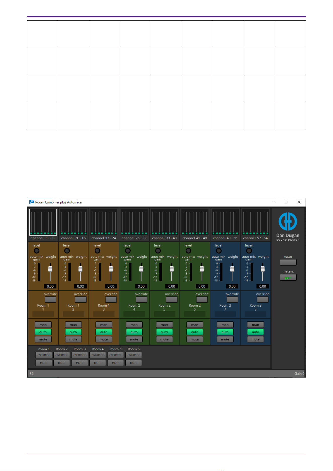
2.8.6. Dugan Automixer window (Room Combiner plus Automixer)
This customizes the “Dugan Automixer” component for use with Room Combiner plus Automixer. For
details, refer to “Dugan Automixer” component editor.
Although the “Dugan Automixer” component mixes mics in units of groups, this window does not have a
Group parameter because mics are mixed for each room. The name of the room to which the mic was
originally assigned is shown above the channel number.
2. Audio Components
ProVisionaire Design Component Guide | 31
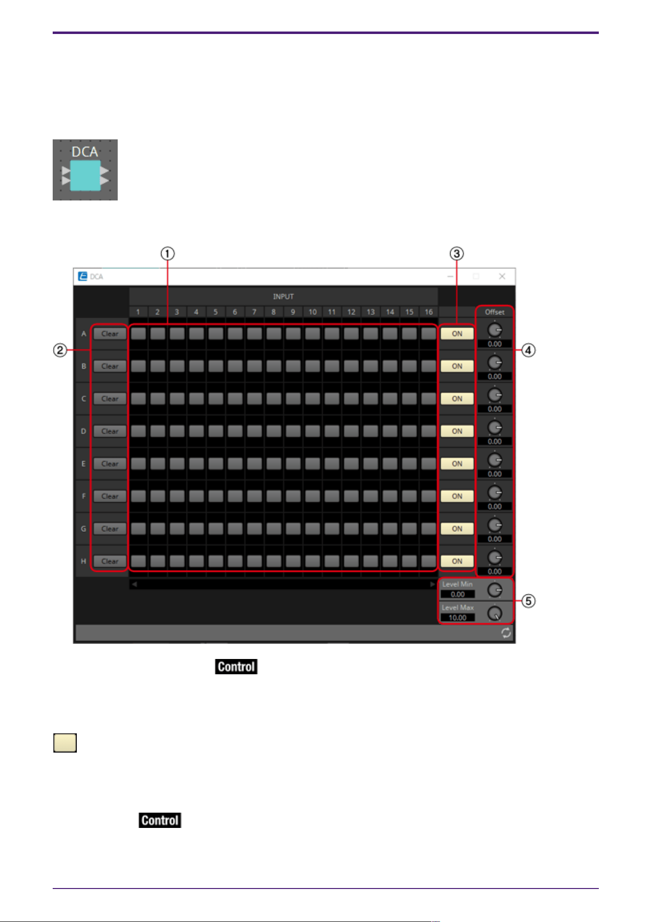
2.9. DCA
DCA is a function that registers the input system channels into 8 groups, and allows for operations
such as simultaneous muting, or batch level operation using the Offset knob. If the input system
channels all belong to the same group, the levels can be operated with a single Offset knob while still
retaining the level differences between the channels. This is useful when grouping mics for drums.
2.9.1. “DCA” component editor
① Registered channel matrix
This is the matrix to register channels into groups. The group name (A to H) is shown on the vertical
axis, and the registerable channel names are shown on the horizontal axis. A group can be registered by
clicking on the intersection of the two axes. If there are too many channels to display on the screen, a
scroll bar will be displayed at the bottom.
: Register
② [Clear] button
This button removes all the channels registered to a group.
③ [ON] button
This button switches between on and off for each group. When set to off, the signals registered to
this group are muted.
2. Audio Components
32 | ProVisionaire Design Component Guide
: On
:Off (mute)
If any input signal has been registered to multiple groups, that signal will be muted when any of the
groups to which it has been registered are turned off.
④ [Offset] knob
The offset value added to the input channels registered to the group. If any input signal has been
registered to multiple groups, the offset values from any of the groups to which it has been registered
will be added before it is output.
⑤ [Level Min]/[Level Max] knobs
Sets the upper and lower limits of the offset.
2.9.2. Control
Parameter types of the input/output values for each Port
Input Value Control Parameter Output Value
Type Range Input
Port
Name
Paramete
r Range
Output
Port
Name
Type Range
Value Num 0,1 ● A In1
OFF:0,
ON:1
● A In1 Value Num
OFF:0,
ON:1
Value Num 0,1 ● B In1
OFF:0,
ON:1
● B In1 Value Num
OFF:0,
ON:1
Value Num 0,1 ● C In1
OFF:0,
ON:1
● C In1 Value Num
OFF:0,
ON:1
Value Num 0,1 ● D In1
OFF:0,
ON:1
● D In1 Value Num
OFF:0,
ON:1
Value Num 0,1 ● E In1
OFF:0,
ON:1
● E In1 Value Num
OFF:0,
ON:1
Value Num 0,1 ● F In1
OFF:0,
ON:1
● F In1 Value Num
OFF:0,
ON:1
Value Num 0,1 ● G In1
OFF:0,
ON:1
● G In1 Value Num
OFF:0,
ON:1
Value Num 0,1 ● H In1
OFF:0,
ON:1
● H In1 Value Num
OFF:0,
ON:1
Value Num 0,1 ● On A
OFF:0,
ON:1
● On A Value Num
OFF:0,
ON:1
Value dB −∞–10.00 ● Offset
A
−∞–10.00 ● Offset
A
Value dB −∞–10.00
Normalized 0.00–10.0
0
2. Audio Components
ProVisionaire Design Component Guide | 33
2.10. Delay
In a sound system that includes multiple speaker units, it may appear to a listener that the voice of
the person talking is originating from a nearby speaker unit, rather than from the actual person. In
such cases, you can correct the perceived localization by delaying the audio of the nearby speaker unit
in proportion to the distance between the speaker unit near the person who is talking and the speaker
unit that is far from that person.
If sound from different speaker units is mutually interfering, adding a slight delay to one of the audio
signals will shift the interfering frequencies, lessening the unnatural sensation.
When placing this in the design sheet, select either Mono, Stereo or Multi. The illustrations used in the
following explanation are for the case of Stereo.
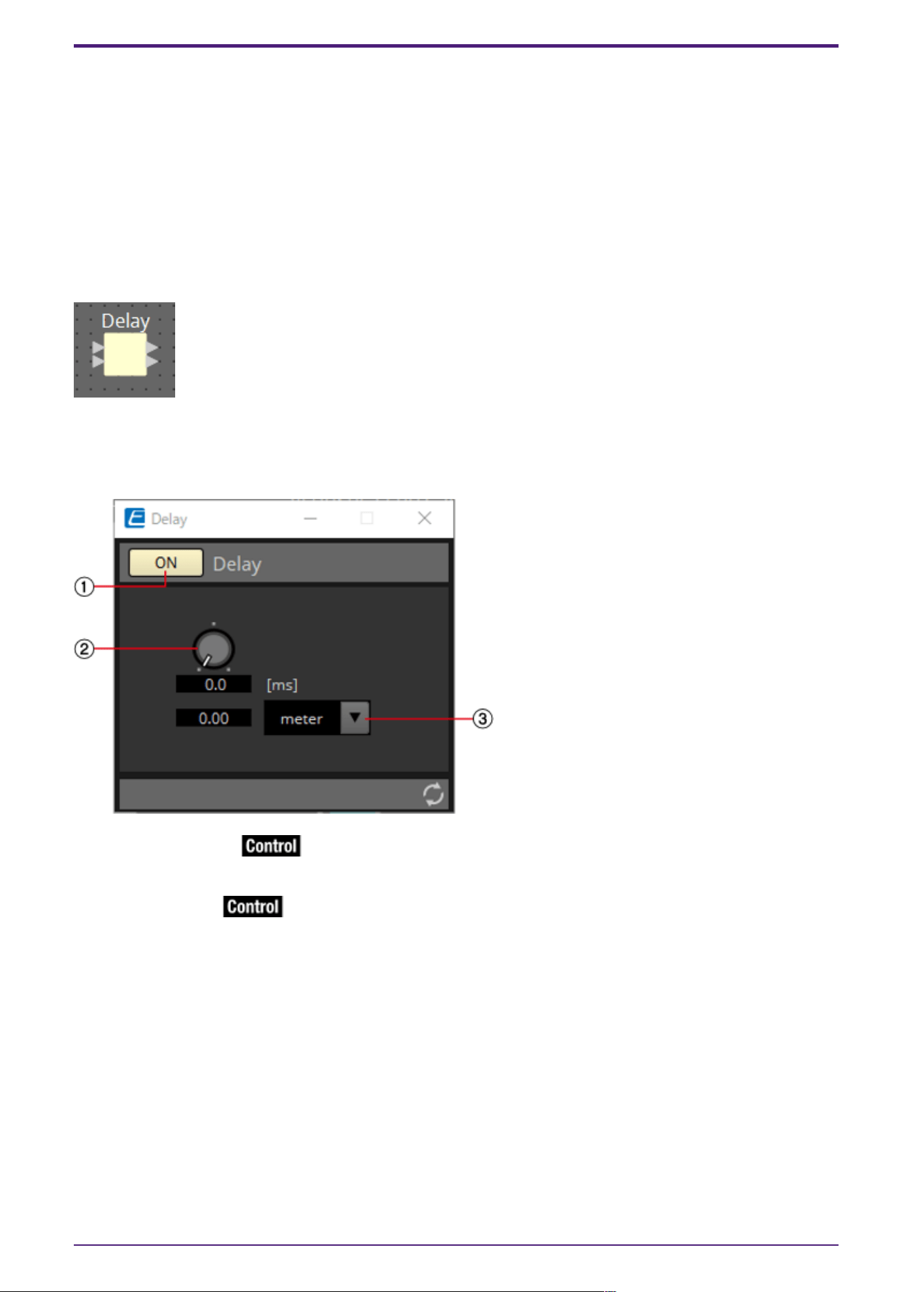
2.10.1. ”Delay” component editor
Here you can specify the amount of delay in terms of time or distance.
① Delay [ON] button
Switches the delay function between enabled and disabled.
② Delay Time knob
Specifies the delay time.
③ Type list box
The delay time specified by the Delay Time knob is converted into the units you select, and shown at
the left.
2. Audio Components
34 | ProVisionaire Design Component Guide

2.10.2. Control
Parameter types of the input/output values for each Port
Input Value Control Parameter Output Value
Type Range Input
Port
Name
Paramete
r Range
Output
Port
Name
Type Range
Value Num 0,1 ● On
OFF:0,
ON:1
● On Value Num
OFF:0,
ON:1
Value dB −∞–10.00 ● Delay
Time
−∞–10.00 ● Delay
Time
Value dB −∞–10.00
Normalized 0.00–1.00
2. Audio Components
ProVisionaire Design Component Guide | 35
2.11. Dynamics: Compressor
This type of signal processing compresses the dynamic range. Use this to prevent problems that can
occur in the sound if the input exceeds a certain level (threshold).
When placing this in the design sheet, select either Mono, Stereo or Multi. The illustrations used in the
following explanation are for the case of Stereo.
The bottom input is for inputting the key-in signal.
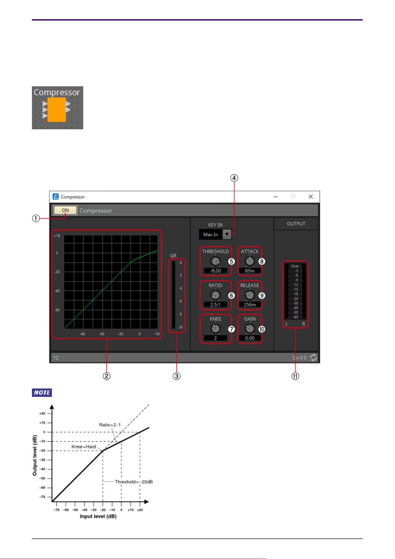
2.11.1. “Compressor” component editor
When Multi is selected, the ⑪ meter is not displayed. Please use the separate Meter component.
2. Audio Components
36 | ProVisionaire Design Component Guide

① Compressor [ON] button
Switches the compressor function between enabled and disabled.
② Compressor curve
This shows the effect as a graph. The horizontal axis is the input signal level, and the vertical axis is
the output signal level.
③ [GR] meter
Indicates the amount of gain reduction.
④ [KEY IN] list box
From this list, select the input signal that is used as the key-in signal; that is, the reference signal
that causes the compressor to operate.
The following choices are provided.
•
[Self]
For a monaural channel component, the input signal is used as the trigger source.
•
[L]
For a stereo channel component, the L input signal is used as the trigger source.
•
[R]
For a stereo channel component, the R input signal is used as the trigger source.
•
[KeyIn]
The key-in input is used as the trigger source.
•
[Max In]
This sets the signal with the largest value in a stereo channel or a multi-channel component as
the trigger source.
•
1~64
This sets the specified channel signal in a multi-channel component as the trigger source.
⑤ [THRESHOLD] knob
Specifies the threshold level at which the compressor will take effect.
⑥ [RATIO] knob
Specifies the compression ratio.
When the threshold level is exceeded, the output signal will be adjusted at the ratio specified by
“input signal : output signal.” For example with a setting of 4:1, the portion of the signal that exceeds
the threshold value will be compressed to 1/4th.
⑦ [KNEE] knob
Specifies how compression will be applied.
With the [HARD] setting, compression will operate like a limiter. If the [HARD] setting produces an
unnatural impression, raise the value. However, raising the value excessively will increase the amount
of compression for the portion below the threshold level.
⑧ [ATTACK] knob
Specifies the attack time (the time from when the input signal exceeds the threshold until the
maximum compression is reached).
⑨ [RELEASE] knob
Specifies the release time (the time from when the input signal falls below the threshold until
compression is no longer applied).
2. Audio Components
ProVisionaire Design Component Guide | 37

⑩ [GAIN] knob
Sets the gain of the output signal.
⑪ [OUTPUT]メーター
Shows the output signal level.
2.11.2. Control
There are no parameters that can be controlled through the Control layer.
2. Audio Components
38 | ProVisionaire Design Component Guide
2.12. Dynamics: Comp260
This is an analog-flavored compressor built using Yamaha’s proprietary VCM (Virtual Circuitry
Modeling) technology. It emulates the characteristics of compressors and limiters of the mid-1970s,
which are now a standard for live sound reinforcement. This compressor has faithfully modeled the
VCA (Voltage Controlled Amplifier) circuit and the RMS (Root Mean Square) detection circuit.
Compression curve (Knee) can be set to Hard, Medium, or Soft. Attack time and release time are
variable. The preset settings recreate the fixed value of the early legacy models. Designed under the
supervision of top SR engineers, the parameter effects have been optimized for live sound
reinforcement.
When placing this in the design sheet, select either Mono, Stereo or Multi. The illustrations used in the
following explanation are for the case of Stereo.
The bottom input is for inputting the key-in signal.
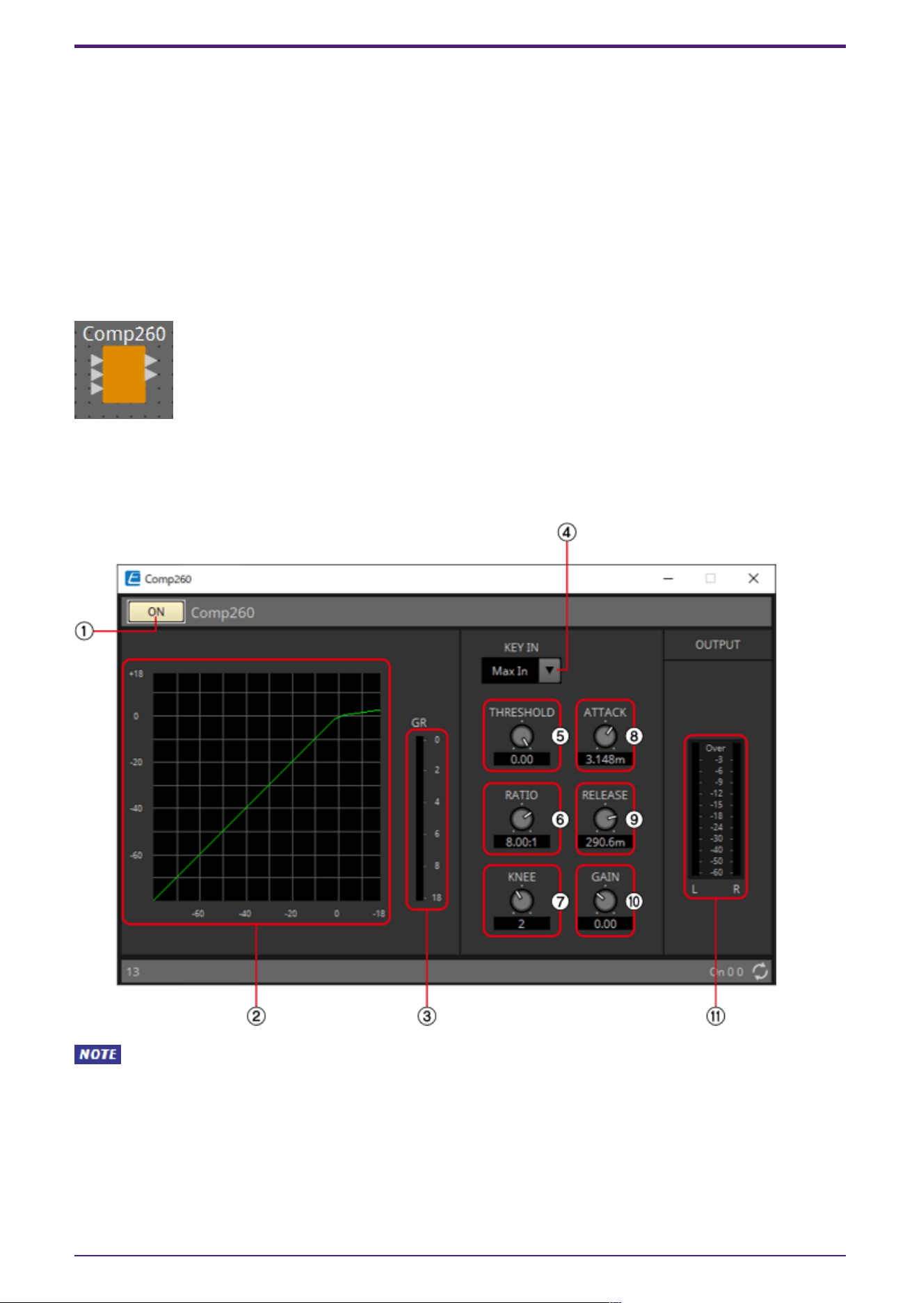
2.12.1. ”Comp260” component editor
When Multi is selected, the ⑪ meter is not displayed. Please use the separate Meter component.
2. Audio Components
ProVisionaire Design Component Guide | 39
① Comp260 [ON] button
Switches between enabling or disabling the Comp260 function.
② Compressor curve
This shows the effect as a graph. The horizontal axis is the input signal level, and the vertical axis is
the output signal level.
③ [GR] meter
Indicates the amount of gain reduction.
④ [KEY IN] list box
From this list, select the input signal that is used as the key-in signal; that is, the reference signal
that causes the compressor to operate.
The following choices are provided.
•
[Self]
For a monaural channel component, the input signal is used as the trigger source.
•
[L]
For a stereo channel component, the L input signal is used as the trigger source.
•
[R]
For a stereo channel component, the R input signal is used as the trigger source.
•
[KeyIn]
The key-in input is used as the trigger source.
•
[Max In]
This sets the signal with the largest value in a stereo channel or a multi-channel component as
the trigger source.
•
1~64
This sets the specified channel signal in a multi-channel component as the trigger source.
⑤ [THRESHOLD] knob
Specifies the threshold level at which the Comp260 will take effect.
⑥ [RATIO] knob
Specifies the Comp260 ratio.
When the threshold level is exceeded, the output signal will be adjusted at the ratio “input signal :
output signal.” For example with a setting of 4:1, the portion of the signal that exceeds the threshold
value will be compressed to 1/4th.
2. Audio Components
40 | ProVisionaire Design Component Guide

⑦ [KNEE] knob
Specifies how Comp260 will be applied.
With the [HARD] setting, it will operate like a limiter. If the [HARD] setting produces an unnatural
impression, raise the value. However, raising the value excessively will increase the amount of
compression for the portion below the threshold level.
⑧ [ATTACK] knob
Specifies the attack time (the time from when the input signal exceeds the threshold until the
maximum Comp260 effect is reached).
⑨ [RELEASE] knob
Specifies the release time (the time from when the input signal falls below the threshold until
Comp260 is no longer applied).
⑩ [GAIN] knob
Sets the gain of the output signal.
⑪ [OUTPUT] meter
Shows the output signal level.
2.12.2. Control
There are no parameters that can be controlled through the Control layer.
2. Audio Components
ProVisionaire Design Component Guide | 41
2.13. Dynamics: De-Esser
Detects only high-frequency consonant components such as sibilant sounds (hissing or buzzing sounds)
in vocals and compresses that band.
When placing this in the design sheet, select either Mono or Stereo. The illustrations used in the
following explanation are for the case of Stereo.
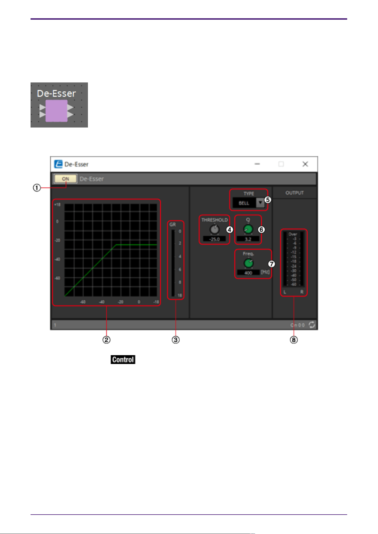
2.13.1. ”De-Esser” component editor
① De-Esser [ON] button
Switches the De-Esser function between enabled and disabled.
② Dynamics graph
This shows the effect as a graph. The horizontal axis is the input signal level, and the vertical axis is
the output signal level.
③ [GR] meter
Indicates the amount of gain reduction.
④ [THRESHOLD] knob
Specifies the threshold level at which the De-Esser will take effect.
⑤ [Type] list box
Enables you to select a filter type.
2. Audio Components
42 | ProVisionaire Design Component Guide
⑥ [Q] knob
Specifies the Q of the filter.
When the type is H.SHELF, the Q is not displayd.
⑦ [Freq.] knob
Specifies the cutoff frequency of the filter.
⑧ [OUTPUT] meter
Shows the output signal level.
2.13.2. Control
Parameter types of the input/output values for each Port
Input Value Control Parameter Output Value
Type Range Input
Port
Name
Paramete
r Range
Output
Port
Name
Type Range
Value Num 0,1 ● On
OFF:0,
ON:1
● On Value Num
OFF:0,
ON:1
2. Audio Components
ProVisionaire Design Component Guide | 43
2.14. Dynamics: Ducker
This function reduces the audio signal level (volume) of the input channel when an audio signal is input
to a specific channel. For example if this is used on background music and the key-in source is assigned
to a channel with a mic connected, the background music will automatically diminish when an
announcement is made into that mic, and automatically return to the original volume when the
announcement is over.
When placing this in the design sheet, select either Mono, Stereo or Multi. The illustrations used in the
following explanation are for the case of Stereo.
The bottom input is for inputting the key-in signal.
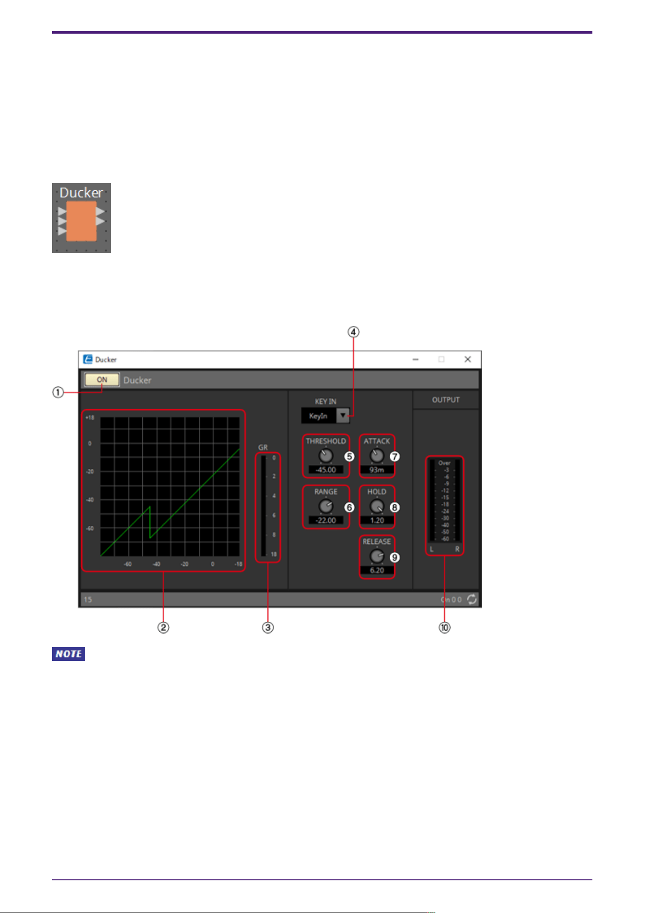
2.14.1. ”Ducker” component editor
When Multi is selected, the ⑩meter is not displayed. Please use the separate Meter component.
2. Audio Components
44 | ProVisionaire Design Component Guide
① Ducker [ON] button
Switches the Ducker function between enabled and disabled.
② Ducking curve
This shows the effect as a graph. The horizontal axis is the input signal level, and the vertical axis is
the output signal level.
③ [GR] meter
Indicates the amount of gain reduction.
④ [KEY IN] list box
From this list, select the input signal that is used as the key-in signal; that is, the reference signal
that causes Ducker to operate.
The following choices are provided.
•
[Self]
For a monaural channel component, the input signal is used as the trigger source.
•
[L]
For a stereo channel component, the L input signal is used as the trigger source.
•
[R]
For a stereo channel component, the R input signal is used as the trigger source.
•
[KeyIn]
The key-in input is used as the trigger source.
•
[Max In]
This sets the signal with the largest value in a stereo channel or a multi-channel component as
the trigger source.
•
1~64
This sets the specified channel signal in a multi-channel component as the trigger source.
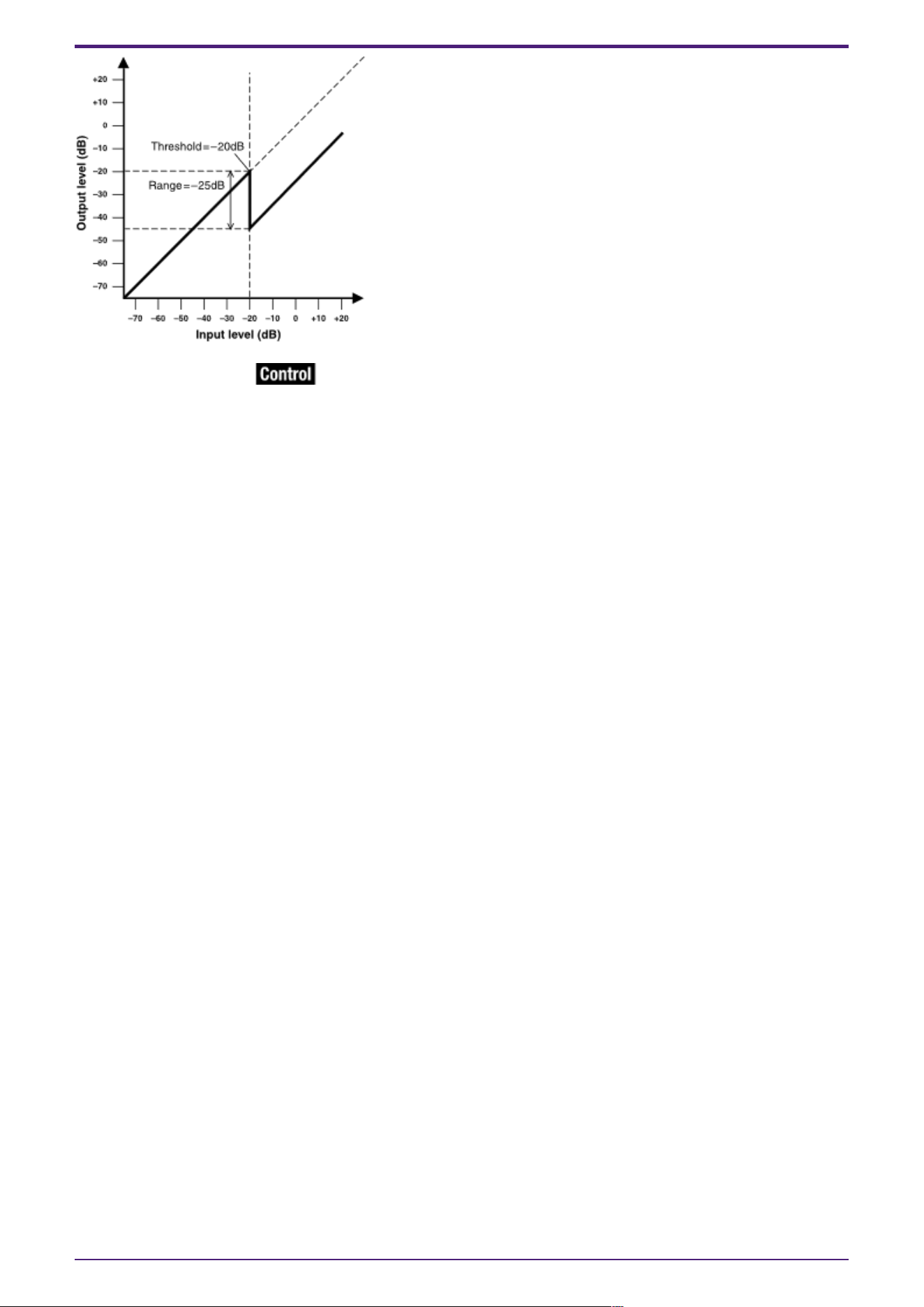
⑤ [THRESHOLD] knob
Specifies the threshold level at which Ducker is applied.
⑥ [RANGE] knob
Specifies the amount of attenuation applied when Ducker is active.
⑦ [ATTACK] knob
Specifies the attack time (the time from when the input signal exceeds the THRESHOLD until the
amount of attenuation specified by the [RANGE] knob is reached).
2. Audio Components
ProVisionaire Design Component Guide | 45
⑧ [HOLD] knob
Specifies the hold time (the time from when the input signal falls below the THRESHOLD until
attenuation begins to be removed).
⑨ [RELEASE] knob
Specifies the release time (the time from when the hold time specified by the [HOLD] knob has
elapsed until Ducker is no longer applied). The setting is expressed as the time required for the level to
change 6 dB.
⑩ [OUT] meter
Shows the output signal level.
2.14.2. Control
Parameter types of the input/output values for each Port
Input Value Control Parameter Output Value
Type Range Input
Port
Name
Paramete
r Range
Output
Port
Name
Type Range
Value Num 0,1 ● On
OFF:0,
ON:1
● On Value Num
OFF:0,
ON:1
2. Audio Components
46 | ProVisionaire Design Component Guide
2.15. Dynamics: Gate
This type of signal processing passes the audio signal only while it exceeds a specified volume. Use this
to cut low-level noise, such as when there is no input from a mic, or when the input is below a specified
level (the threshold value).
When placing this in the design sheet, select either Mono, Stereo or Multi. The illustrations used in the
following explanation are for the case of Stereo.
The bottom input is for inputting the key-in signal.
2.15.1. ”Gate” component editor
When Multi is selected, the ⑩ meter is not displayed. Please use the separate Meter component.
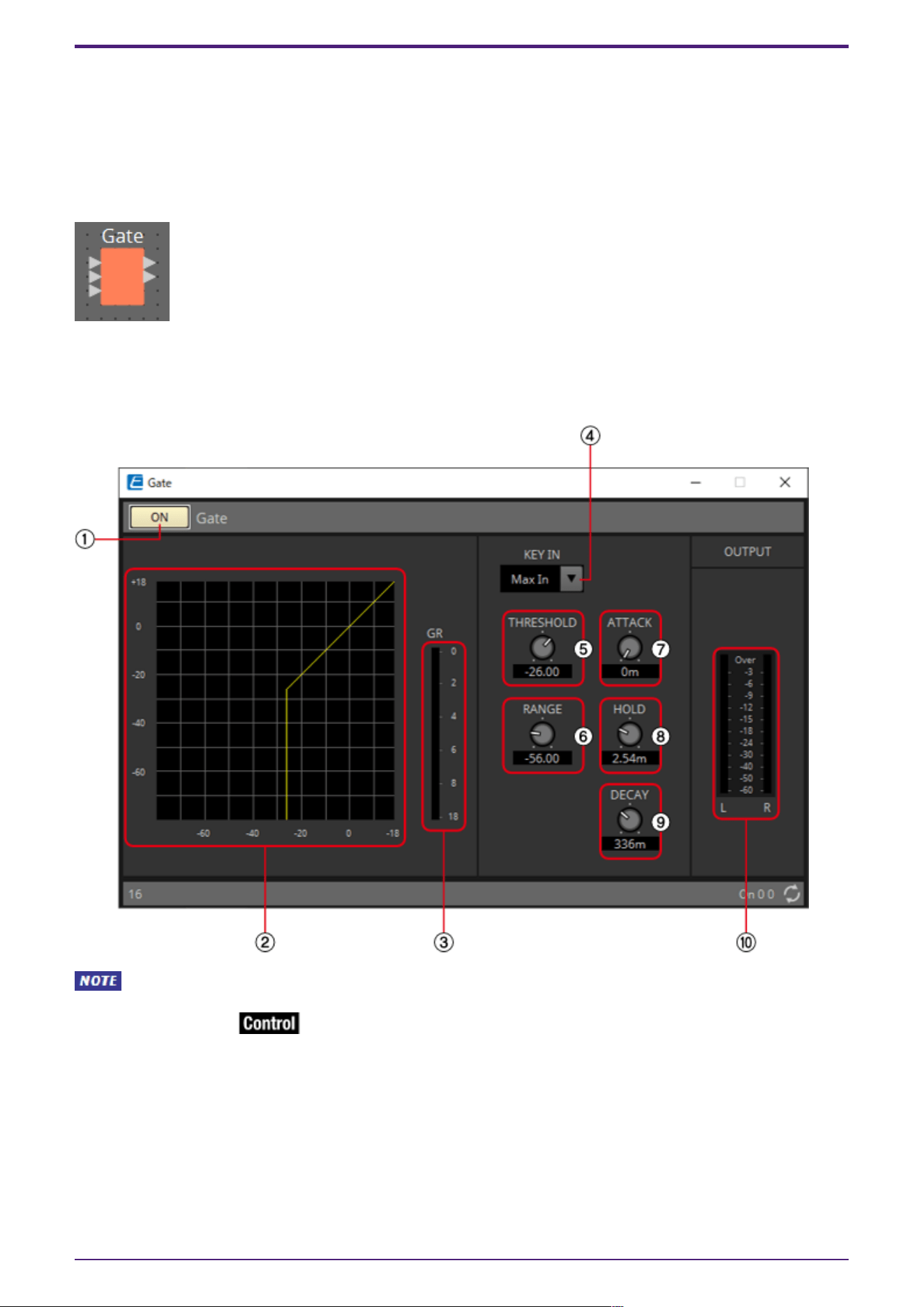
① Gate [ON] button
Switches the gate function between enabled and disabled.
② Gate curve
This shows the effect as a graph. The horizontal axis is the input signal level, and the vertical axis is
the output signal level.
③ [GR] meter
Indicates the amount of gain reduction.
2. Audio Components
ProVisionaire Design Component Guide | 47

④ [KEY IN] list box
From this list, select the input signal that is used as the key-in signal; that is, the reference signal
that causes the gate to operate.
The following choices are provided.
•
[Self]
For a monaural channel component, the input signal is used as the trigger source.
•
[L]
For a stereo channel component, the L input signal is used as the trigger source.
•
[R]
For a stereo channel component, the R input signal is used as the trigger source.
•
[KeyIn]
The key-in input is used as the trigger source.
•
[Max In]
This sets the signal with the largest value in a stereo channel or a multi-channel component as
the trigger source.
•
1~64
This sets the specified channel signal in a multi-channel component as the trigger source.
⑤ [THRESHOLD] knob
Specifies the threshold level at which the gate will take effect.
⑥ [RANGE] knob
Specifies the amount of attenuation applied when the gate is active.
⑦ [ATTACK] knob
Specifies the attack time (the time from when the input signal exceeds the threshold until the gate
opens).
⑧ [HOLD] knob
Specifies the hold time (the time from when the input signal falls below the threshold until the gate
begins to close).
⑨ [DECAY] knob
Specifies the decay time (the time over which the gate closes after the hold time has elapsed).
⑩ [OUT] meter
Shows the output signal level.
2. Audio Components
48 | ProVisionaire Design Component Guide

2.15.2. Control
Parameter types of the input/output values for each Port
Input Value Control Parameter Output Value
Type Range Input
Port
Name
Paramete
r Range
Output
Port
Name
Type Range
Value Num 0,1 ● On
OFF:0,
ON:1
● On Value Num
OFF:0,
ON:1
- - - -
OFF:0,
ON:1
● Gate
Open
Value Num 0,1
2. Audio Components
ProVisionaire Design Component Guide | 49
2.16. Dynamics: Limiter
Input signals that exceed the threshold value are compressed ∞:1, preventing signals greater than the
threshold value from being output. This is used mainly to keep power amps and speaker systems from
being damaged by excessive input.
When placing this in the design sheet, select either Mono, Stereo or Multi. The illustrations used in the
following explanation are for the case of Stereo.
The bottom input is for inputting the key-in signal.
2.16.1. ”Limiter” component editor
When Multi is selected, the ⑧ meter is not displayed. Please use the separate Meter component.
2. Audio Components
50 | ProVisionaire Design Component Guide
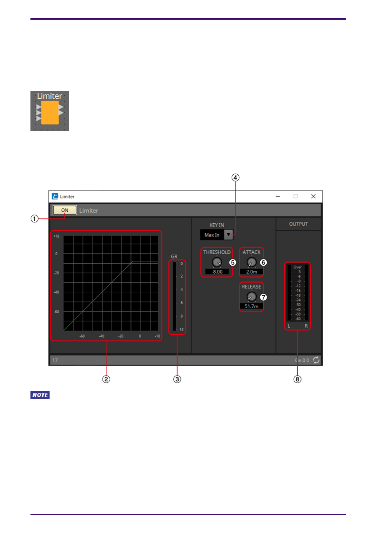
① Limiter [ON] button
Switches the limiter function between enabled and disabled.
② Limiter curve
This shows the effect as a graph. The horizontal axis is the input signal level, and the vertical axis is
the output signal level.
③ [GR] meter
Indicates the amount of gain reduction.
④ [KEY IN] list box
From this list, select the input signal that is used as the key-in signal; that is, the reference signal
that causes the limiter to operate.
The following choices are provided.
•
[Self]
For a monaural channel component, the input signal is used as the trigger source.
•
[L]
For a stereo channel component, the L input signal is used as the trigger source.
•
[R]
For a stereo channel component, the R input signal is used as the trigger source.
•
[KeyIn]
The key-in input is used as the trigger source.
•
[Max In]
This sets the signal with the largest value in a stereo channel or a multi-channel component as
the trigger source.
•
1~64
This sets the specified channel signal in a multi-channel component as the trigger source.
⑤ [THRESHOLD] knob
Specifies the threshold level at which the limiter is applied.
⑥ [ATTACK] knob
Specifies the attack time (the time from when the input signal exceeds the threshold until the
maximum limiter effect is reached).
2. Audio Components
ProVisionaire Design Component Guide | 51
⑦ [RELEASE] knob
Specifies the release time (the time from when the input signal falls below the threshold until the
limiter effect is no longer applied).
⑧ [OUTPUT] meter
Shows the output signal level.
2.16.2. Control
Parameter types of the input/output values for each Port
Input Value Control Parameter Output Value
Type Range Input
Port
Name
Paramete
r Range
Output
Port
Name
Type Range
Value Num 0,1 ● On
OFF:0,
ON:1
● On Value Num
OFF:0,
ON:1
Value dB −∞–10.00 ●
Threshold
−∞–10.00 ●
Threshold
Value dB −∞–10.00
Normalized 0.00–1.00
- - - -
OFF:0,
ON:1
●
Exceeded
Value Num 0,1
2. Audio Components
52 | ProVisionaire Design Component Guide
2.17. Dynamics: Paging Ducker
This function controls the audio signal level of the program source by the on/off status of the
TRIGGER [ON] button.
Since the TRIGGER [ON] button and [RANGE] indicator can be registered to GPI or the Remote Control
Setup List, they can be controlled from an external device or made to light an external LED.
When placing this in the design sheet, select either Mono, Stereo or Multi. The illustrations used in the
following explanation are for the case of Stereo.
The bottom input is for inputting the key-in signal.
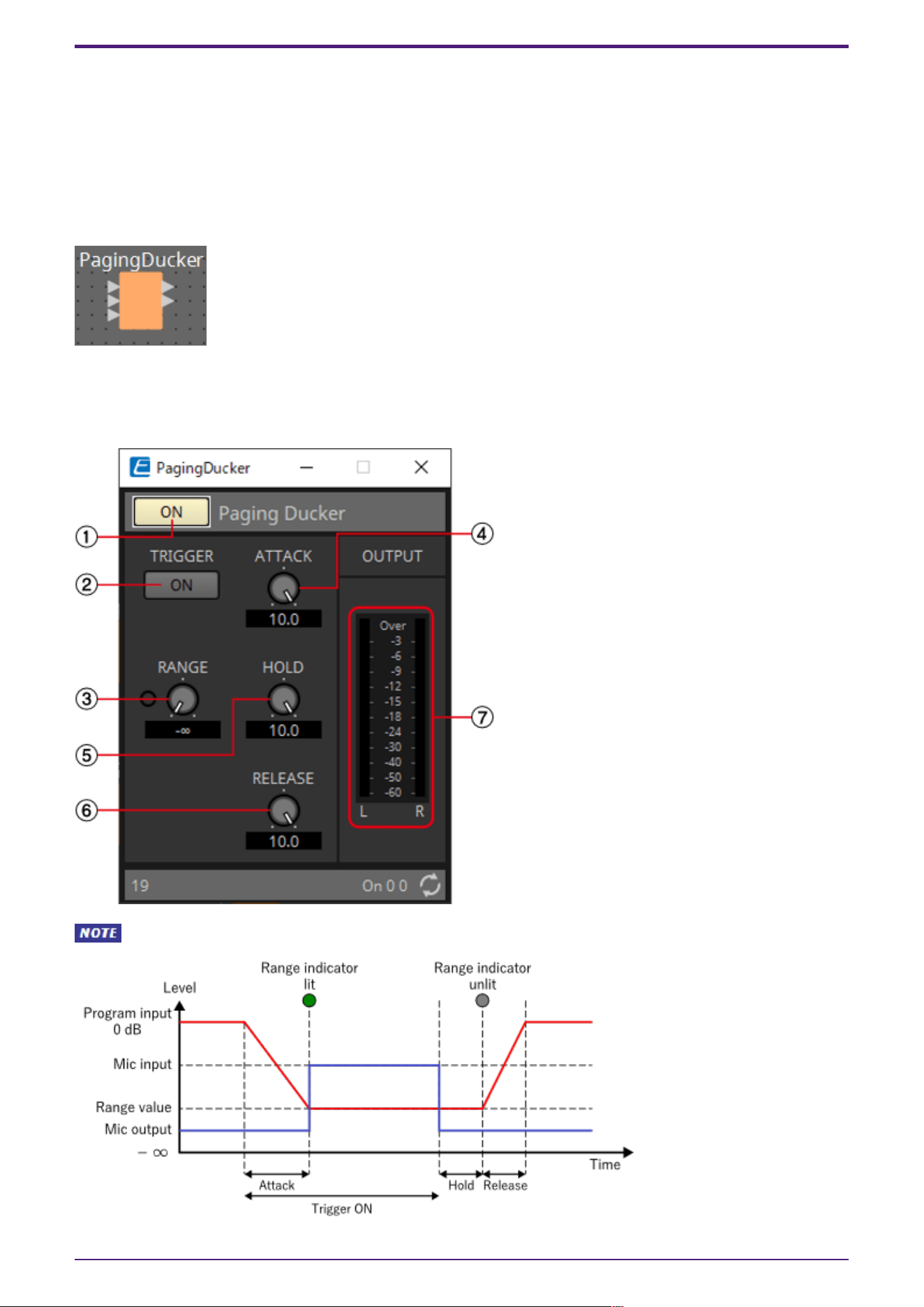
2.17.1. ”Paging Ducker” component editor
When Multi is selected, the meter is not displayed. Please use the separate Meter component.
2. Audio Components
ProVisionaire Design Component Guide | 53
① Paging Ducker [ON] button
Switches the paging ducker function between enabled and disabled.
② TRIGGER [ON] button
If you turn this on, the audio signal level of the program source is lowered to the value specified by
the [RANGE] knob. If you turn this off, the audio signal level of the program source returns to its
original level. Set this so that it operates in tandem with the talk switch/button of the paging mic.
③ [RANGE] knob/indicator
The knob sets the audio signal level of the program source when the TRIGGER [ON] button is on. The
indicator is lit when the signal decreases to the level specified by the knob. If you attach an LED to
GPI and register the [RANGE] indicator to GPI, you’ll be able to check whether the paging mic is active.
④ [ATTACK] knob
Specifies the time over which the audio signal level of the program source decreases to the level
specified by the [RANGE] knob, starting when the TRIGGER [ON] button turns on.
⑤ [HOLD] knob
Specifies the time after which the audio signal level of the program source starts returning to the
original level after the TRIGGER [ON] button turns off.
⑥ [RELEACE] knob
Specifies the time over which the audio signal level of the program source returns to the original level
after the time specified by the [HOLD] knob.
⑦ [OUTPUT] meter
Shows the output signal level.
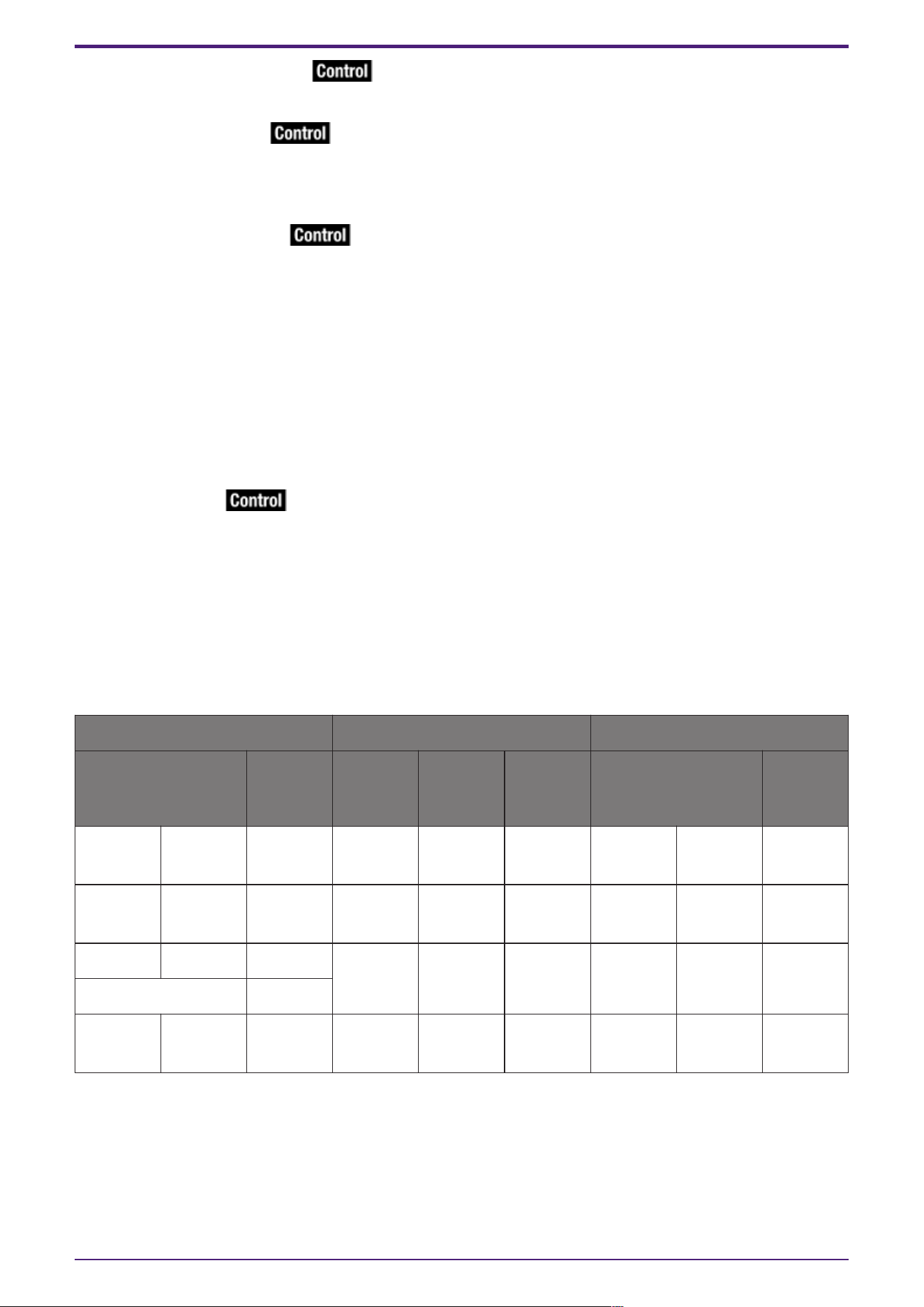
2.17.2. Control
Parameter types of the input/output values for each Port
Input Value Control Parameter Output Value
Type Range Input
Port
Name
Paramete
r Range
Output
Port
Name
Type Range
Value Num 0,1 ● On
OFF:0,
ON:1
● On Value Num
OFF:0,
ON:1
Value Num 0,1 ● Trigger
OFF:0,
ON:1
● Trigger Value Num
OFF:0,
ON:1
Value dB −∞–10.00 ●
Release
−∞–10.00 ●
Release
Value dB −∞–10.00
Normalized 0.00–1.00
- - - -
OFF:0,
ON:1
● Range
Indicator
Value Num 0,1
2. Audio Components
54 | ProVisionaire Design Component Guide
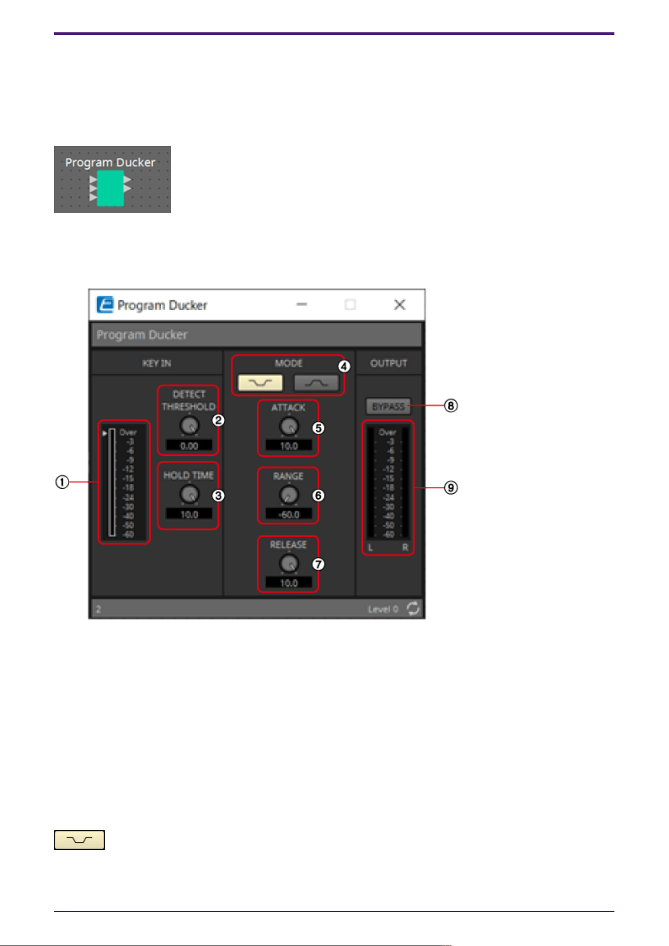
2.18. Dynamics: Program Ducker
When the level of the key-in signal exceeds the threshold, the output signal is attenuated (or the
attenuated signal is returned to its original level).
When placing this in the design sheet, select either Mono, Stereo or Multi. The illustrations used in the
following explanation are for the case of Stereo.
The bottom input is for inputting the key-in signal.
2.18.1. ”Program Ducker” component editor
① [KEY IN] meter
Shows the key-in signal level.
② [DETECT THRESHOLD] knob
Specifies the threshold level at which a key-in signal is detected.
The configured level is indicated by a triangle next to the KeyIn meter.
③ [HOLD TIME] knob
Sets the time to measure the operation even after the key-in signal falls below the threshold after
the key-in signal is detected.
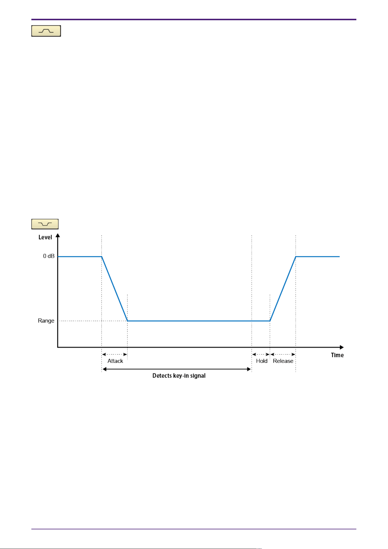
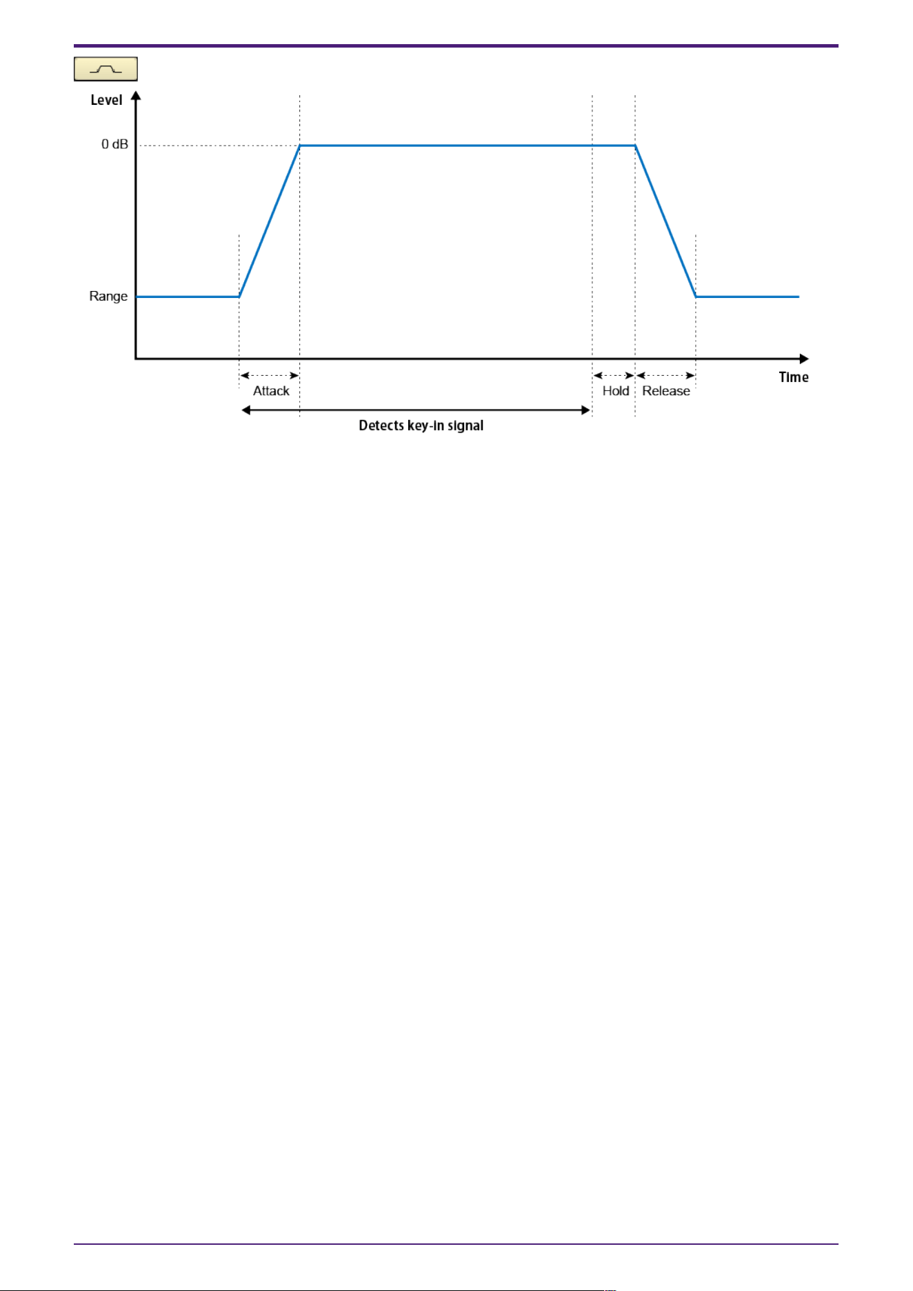
④ [MODE] buttons
Attenuates the output level when the key-in signal is detected. The output level is normally
0 dB. The attenuation level during attenuation is set using RANGE.
2. Audio Components
ProVisionaire Design Component Guide | 55
When the key-in signal is not detected, the output level is attenuated, and when the key-in
signal is detected, the output level is returned to the original level.
The normal attenuation level is set using RANGE. The operating output level is 0 dB.
⑤ [ATTACK] knob
Configures the time it takes to reach the target output level after detecting the key-in signal.
⑥ [RANGE] knob
Sets the level of attenuation. If the MODE is concave, this is the attenuation level when the key-in
signal is detected, and if the MODE is convex, this is the normal level when the key-in signal is not
detected.
⑦ [RELEASE] knob
Sets the amount of time it takes for the output level to return to its original level or attenuate after
the key-in signal falls below the threshold and the HOLD TIME has elapsed.
⑧ [BYPASS] button
Bypasses the attenuation effect.
⑨ [OUTPUT] meter
Shows the output signal level.
2. Audio Components
56 | ProVisionaire Design Component Guide
2.18.2. Control
There are no parameters that can be controlled through the Control layer.
2. Audio Components
ProVisionaire Design Component Guide | 57
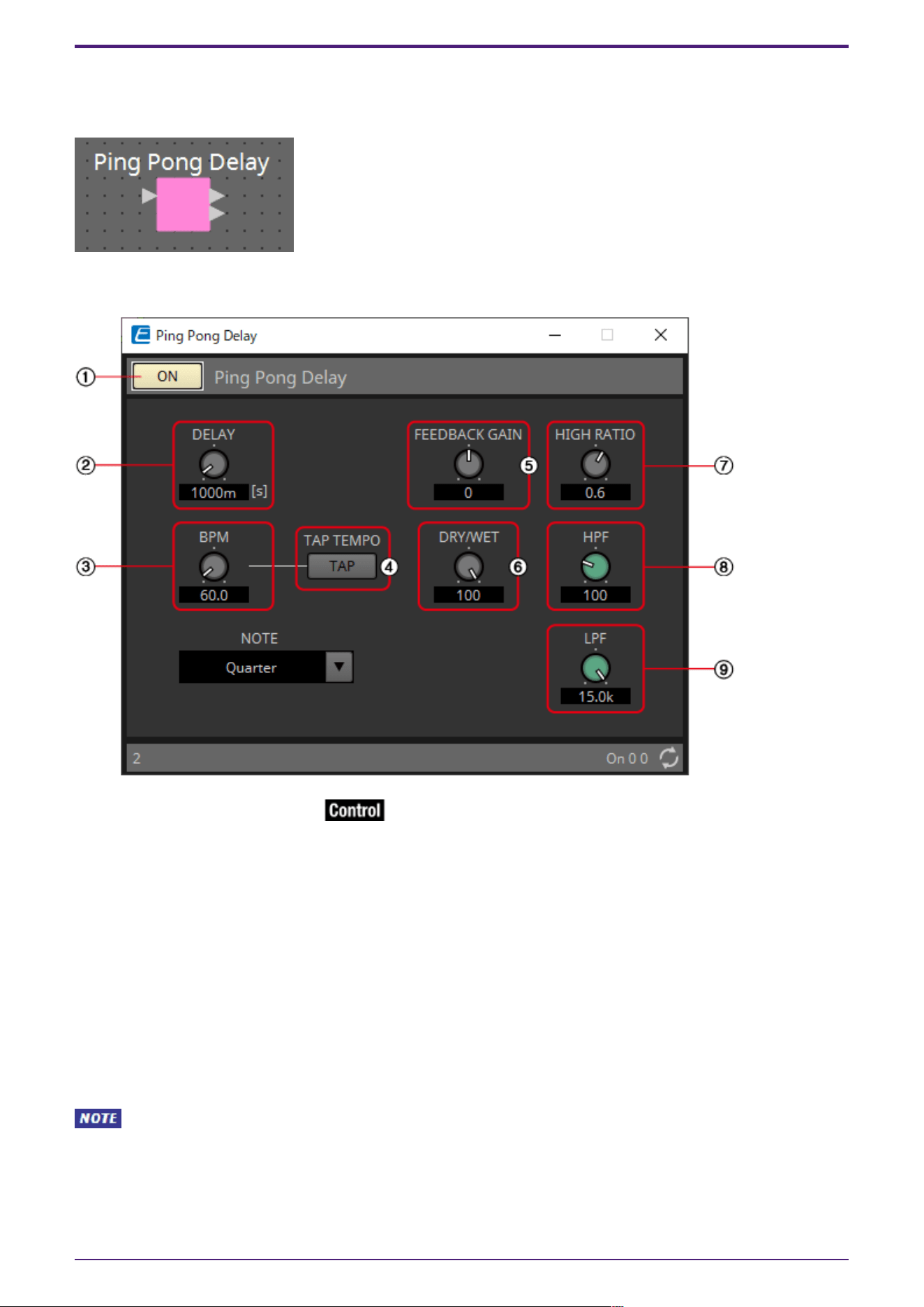
2.19. Effect: Ping Pong Delay
This is a delay effect that repeats the delay sound alternately left and right at equal intervals.
2.19.1. ”Ping Pong Delay” component editor
① Pink Pong Delay [ON] button
Switches the Ping Pong Delay function between enabled and disabled.
② [DELAY] knob
Specifies the delay time.
This will change in conjunction when the BPM or NOTE is changed.
③ [BPM] knob
Specifies the tempo.
④ [TAP TEMPO] button
The BPM will be automatically calculated from the interval between clicks or key presses when a
button is clicked multiple times or return key on the PC is pressed multiple times when the button has
focus.
Determines the criteria for calculating DELAY.
⑤ [FEEDBACK GAIN] knob
Specifies the amount of feedback.
2. Audio Components
58 | ProVisionaire Design Component Guide
⑥ [DRY/WET] knob
This control enables you to adjust the mix balance of the dry and wet (effect) sounds. When the
balance is 0%, only the dry sound is output. When the balance is 100%, only the wet sound is output.
⑦ [HIGH RATIO] knob
Sets the amount of the wide-area component of the feedback.
⑧ [HPF] knob
Sets the high pass filter’s cutoff frequency.
⑨ [LPF] knob
Sets the low pass filter’s cutoff frequency.
2.19.2. Control
Parameter types of the input/output values for each Port
Input Value Control Parameter Output Value
Type Range Input
Port
Name
Paramete
r Range
Output
Port
Name
Type Range
Value Num 0,1 ● On
OFF:0,
ON:1
● On Value Num
OFF:0,
ON:1
2. Audio Components
ProVisionaire Design Component Guide | 59
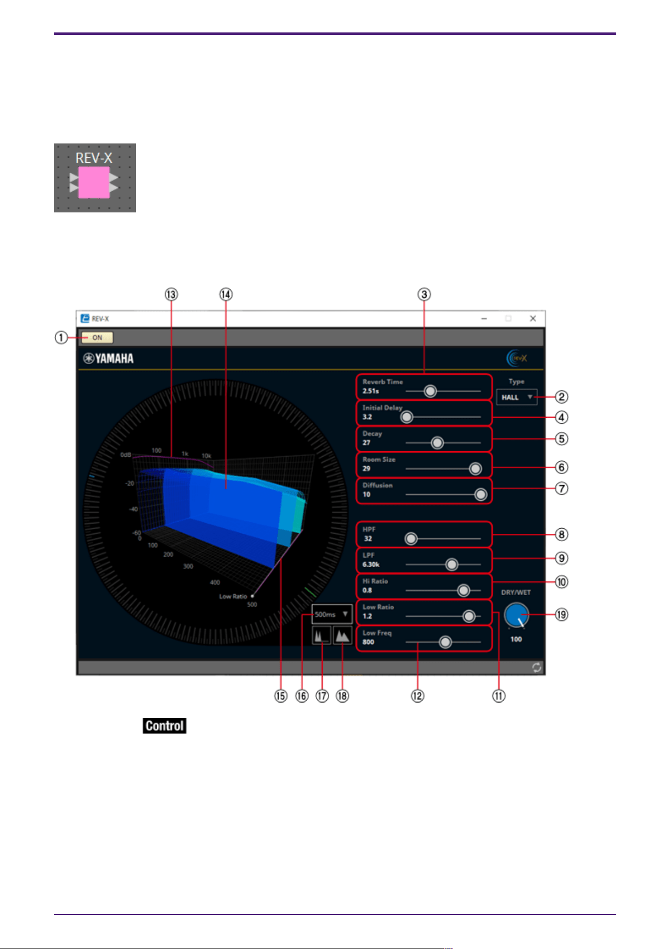
2.20. Effect: REV-X
REV-X is a reverb algorithm that provides a high-density, richly reverberant sound quality, with
smooth attenuation, and spread and depth that work together to enhance the original sound. You can
choose one of three programs to suit the acoustic sound field and your intentions: REV-X Hall, REV-X
Room, and REV-X Plate.
Input and output are stereo, with 1L at the top and 1R below.
2.20.1. ”REV-X” component editor
① [ON] button
Switches the REV-X function between enabled and disabled.
② [Type] list
Enables you to select an effect type.
③ Reverb Time
Duration of time until the reverberation attenuates and stops. Higher values extend the reverberation.
2. Audio Components
60 | ProVisionaire Design Component Guide

④ Initial Delay
Duration of time between sound input and the start of reverberation. Higher values delay the start of
reverberation.
⑤ Decay
Shape of reverberation envelope. Reverberation characteristics are determined by the value.
⑥ Room Size
Size of space. Higher values simulate larger spaces. This value is linked with the Reverb Time value.
When you change this value, the Reverb Time value changes.
⑦ Diffusion
Density and spread of reverberation. Higher values increase the density and enhance the spread.
⑧ HPF
This filter cuts the low frequency range of the reverberation. The range below the frequency specified
by this value is cut. This filter does not affect the original source sound.
⑨ LPF
This filter cuts the high frequency range of the reverberation. The range above the frequency
specified by this value is cut. This filter does not affect the original source sound.
⑩ Hi Ratio
Length of reverberation in the high frequency range. The reverberation duration of the high frequency
range is expressed as a ratio relative to Reverb Time.
⑪ Low Ratio
Length of reverberation in the low frequency range. The reverberation duration of the low frequency
range is expressed as a ratio relative to Reverb Time.
⑫ Low Freq
Frequency value that serves as the basis for the Lo Ratio value. The frequency band below this value is
affected by the Lo Ratio parameter setting.
⑬ Filter frequency response curve
The curve changes depending on the HPF and LPF values.
⑭ Reverberation images
These images represent the high-range (10 kHz), mid-range (1 kHz), and low-range (100 Hz)
reverberation. These images change shape depending on the parameter values. The vertical axis
represents the level; the horizontal axis represents reverb time; the shape represents the envelope.
⑮ Reverb time curve
This curve represents the high-range (10 kHz), mid-range (1 kHz), and low-range (100 Hz) reverb time.
The curve changes depending on the Reverb Time, Hi Ratio, and Lo Ratio parameter values.
⑯ Zoom
This field indicates the time duration (in seconds) as displayed by the time axis (horizontal axis).
⑰ Zoom Out button
Increases the time value (in seconds) as displayed by the time axis (horizontal axis). As a result, the
display zooms out on the horizontal axis.
⑱ Zoom In button
Decreases the time value (in seconds) as displayed by the time axis (horizontal axis). As a result, the
display zooms in on the horizontal axis.
2. Audio Components
ProVisionaire Design Component Guide | 61
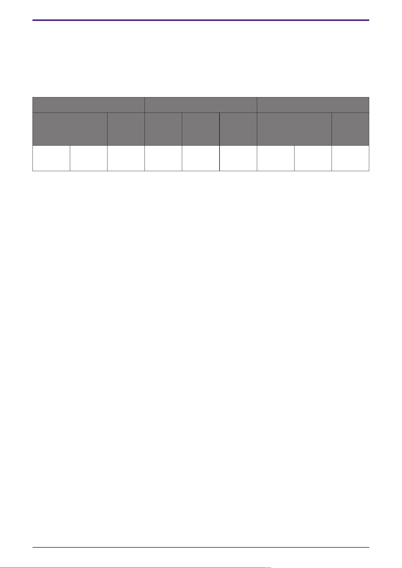
⑲ [DRY/WET] knob
This control enables you to adjust the mix balance of the dry and wet (effect) sounds. When the
balance is 0%, only the dry sound is output. When the balance is 100%, only the wet sound is output.
2.20.2. Control
Parameter types of the input/output values for each Port
Input Value Control Parameter Output Value
Type Range Input
Port
Name
Paramete
r Range
Output
Port
Name
Type Range
Value Num 0,1 ● On
OFF:0,
ON:1
● On Value Num
OFF:0,
ON:1
2. Audio Components
62 | ProVisionaire Design Component Guide
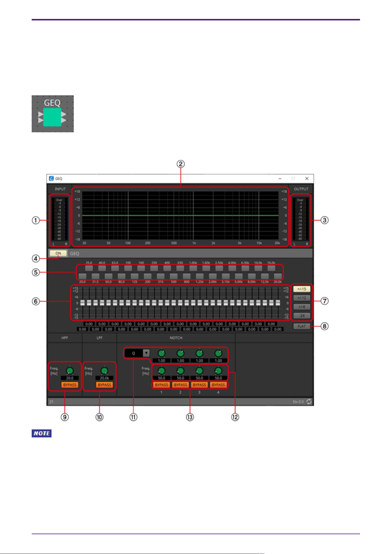
2.21. EQ: GEQ
Here you can make GEQ settings.
When placing the GEQ in the design sheet, you can select the number of bands from 7, 15, or 31. The
illustrations shown here are for when 31 bands are selected.
When placing this in the design sheet, select either Mono, Stereo or Multi and select the number of
bands. The illustrations used in the following explanation are for the case of Stereo.
2.21.1. ”GEQ” component editor
When Multi is selected, the meter is not displayed. Please use the separate Meter component.
① [INPUT] meter
Shows the input signal level.
② EQ curve
This shows the response as a graph.
③ [OUTPUT] meter
Shows the output signal level.
2. Audio Components
ProVisionaire Design Component Guide | 63

④ GEQ [ON] button
Switches the GEQ function between enabled and disabled.
⑤ Bypass buttons
Specify whether each band is bypassed. If you click a button to make it light, that band is bypassed.
⑥ Gain faders
Adjust the output gain of each band.
⑦ [±15]/[±12]/[±6]/[‒24] buttons
Select the range of GEQ gain adjustment. When you click a button, the display of the gain faders and
EQ curve will change to the range you select.
⑧ [FLAT] button
Moves all gain faders to the 0 position.
⑨ [HPF] knob/HPF[BYPASS] button
Specifies the cutoff frequency of the high-pass filter. If you are not using the high-pass filter, click
the [BYPASS] button to turn bypass on (lit).
⑩ [LPF] knob/LPF[BYPASS] button
Specifies the cutoff frequency of the low-pass filter. If you are not using the low-pass filter, click
the [BYPASS] button to turn bypass on (lit).
⑪ [B/W-Q] list/knob
Specifies the width of the frequency band adjusted by the notch filter in the list box, and set the
width with the knob.
⑫ [Freq.] knob
Specifies the center frequency of the notch filter.
⑬ NOTCH [BYPASS] button
Switches the notch filter bypass on/off. If you are not using the notch filter, turn bypass on (lit).
2.21.2. Control
There are no parameters that can be controlled through the Control layer.
2. Audio Components
64 | ProVisionaire Design Component Guide
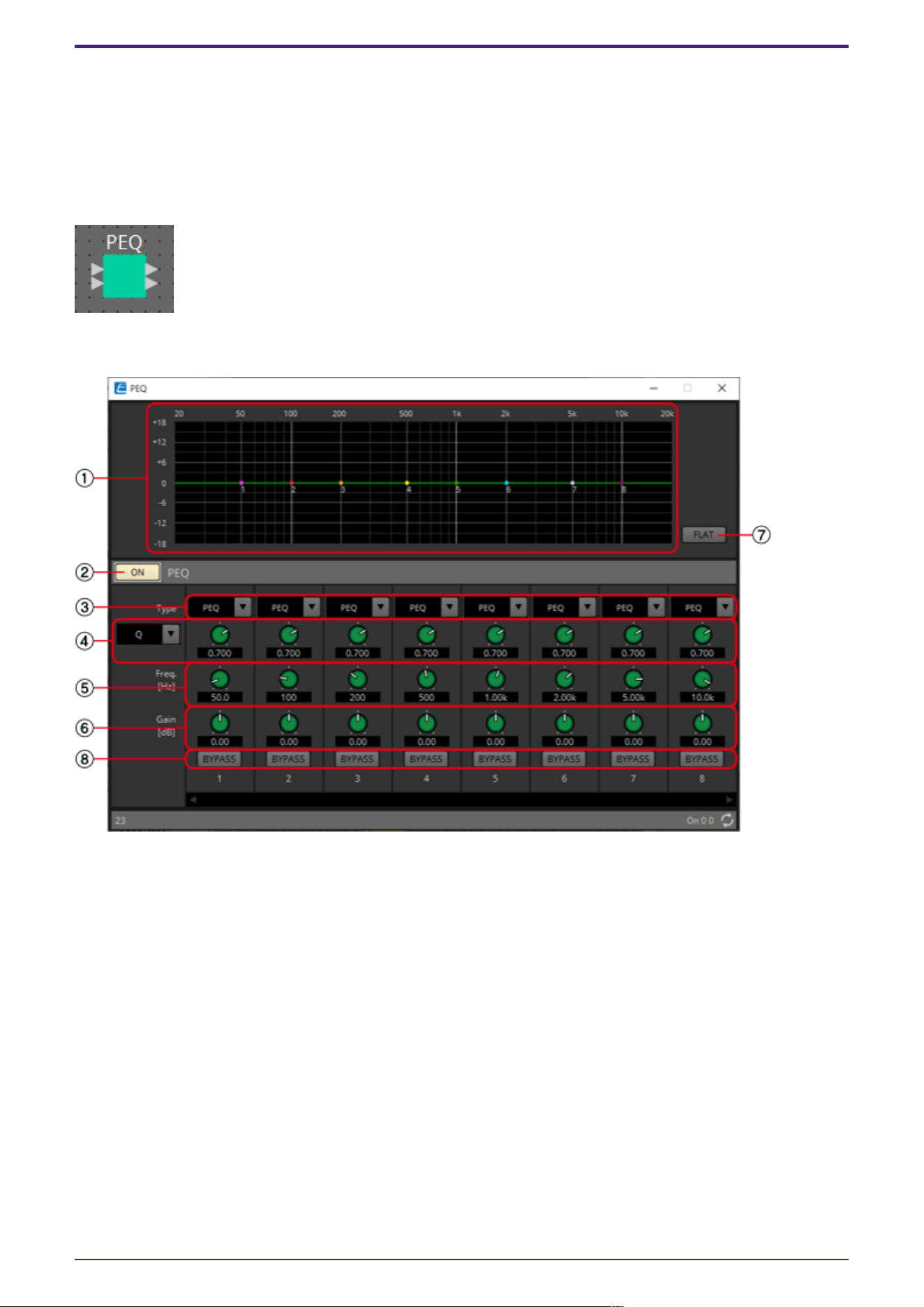
2.22. EQ: PEQ
Here you can make PEQ settings.
When placing the PEQ in the design sheet, you can select the number of bands. The illustrations shown
here are for when 8 bands are selected.
When placing this in the design sheet, select either Mono, Stereo or Multi and select the number of
bands. The illustrations used in the following explanation are for the case of Stereo.
2.22.1. “PEQ” component editor
① EQ curve
This shows the response as a graph. You can change the settings by dragging the points in the graph.
Hold <Shift> key on the computer keyboard while dragging to move in only the horizontal or vertical
direction.
② PEQ [ON] button
Switches the PEQ function between enabled and disabled.
③ [Type] list box
Selects the type of filter that is used for each band. The number of knobs below increases or
decreases according to the type that you select.
The following types of filter are provided.
•
PEQ (Parametric Equalizer)
The volume in the region of the specified frequency will be boosted or cut for the width
specified by the Q setting.
2. Audio Components
ProVisionaire Design Component Guide | 65

•
L.SHELF (Low Shelf)
The volume of the entire low-frequency region below the specified frequency will be boosted or
cut. Use this for purposes such as bass boost. [6dB/Oct] and [12dB/Oct] specify the amount of
attenuation per octave.
•
H.SHELF (High Shelf)
The volume of the entire high-frequency region above the specified frequency will be boosted or
cut. Use this for purposes such as high boost. [6dB/Oct] and [12dB/Oct] specify the amount of
attenuation per octave.
•
HPF (High Pass Filter)
The region below the specified frequency will be cut.
•
LPF (Low Pass Filter)
The region above the specified frequency will be cut.
④ Q-B/W [OCT] list box/knob
Select the type of frequency bandwidth for each band in the list box, and set the width with the knob.
In [B/W], the setting unit is octaves.
⑤ [Freq] knob
Adjusts the center frequency of each band.
⑥ [Gain] knob
Specifies the gain in each band’s frequency region.
⑦ [FLAT] button
Moves all [Gain] knobs to the 0 position.
⑧ [BYPASS] button
Specifies whether each band is bypassed. If you click a button to make it light, that band is bypassed.
2.22.2. Control
There are no parameters that can be controlled through the Control layer.
2. Audio Components
66 | ProVisionaire Design Component Guide
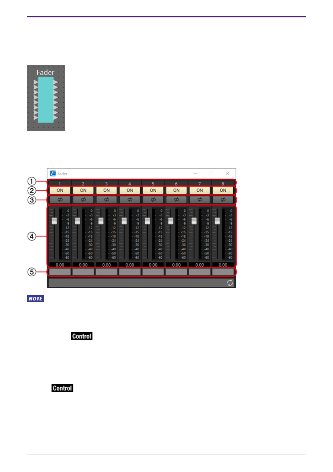
2.23. Fader
This adjusts the output level of each channel.
When placing this in the design sheet, select either Mono, Stereo or Multi, and specify the number of
channels. The illustration used in the following explanation is for the case of eight monaural channels.
When Stereo is selected, the inputs and outputs are 1L, 1R, 2L, and 2R from the top.
2.23.1. “Fader” component editor
MWhen Multi is selected, the meter is not displayed. Please use the separate Meter component.
① Channel index
Indicates the channel number.
② [ON] button
Switches the output of each channel between enabled and disabled.
③ [⌀] button
Specifies whether the phase of the output signal of each channel is inverted. If you click the button to
make it light, the phase of that channel’s output signal is inverted.
④ Fader
This adjusts the output level of each channel. You can right-click the fader to access the context
menu, and select [0 dB] or [-Infinity].
⑤ Port name
Shows or edits the port name. This is linked with the “Label” of the component’s ports.
2. Audio Components
ProVisionaire Design Component Guide | 67

2.23.2. Control
Parameter types of the input/output values for each Port
Input Value Control Parameter Output Value
Type Range Input
Port
Name
Paramete
r Range
Output
Port
Name
Type Range
Value dB −∞–10.00 ● Level
Ch1
−∞–10.00 ● Level
Ch1
Value dB −∞–10.00
Normalized 0.00–1.00
Value Num 0,1 ● On Ch1
OFF:0,
ON:1
● On Ch1 Value Num
OFF:0,
ON:1
2. Audio Components
68 | ProVisionaire Design Component Guide
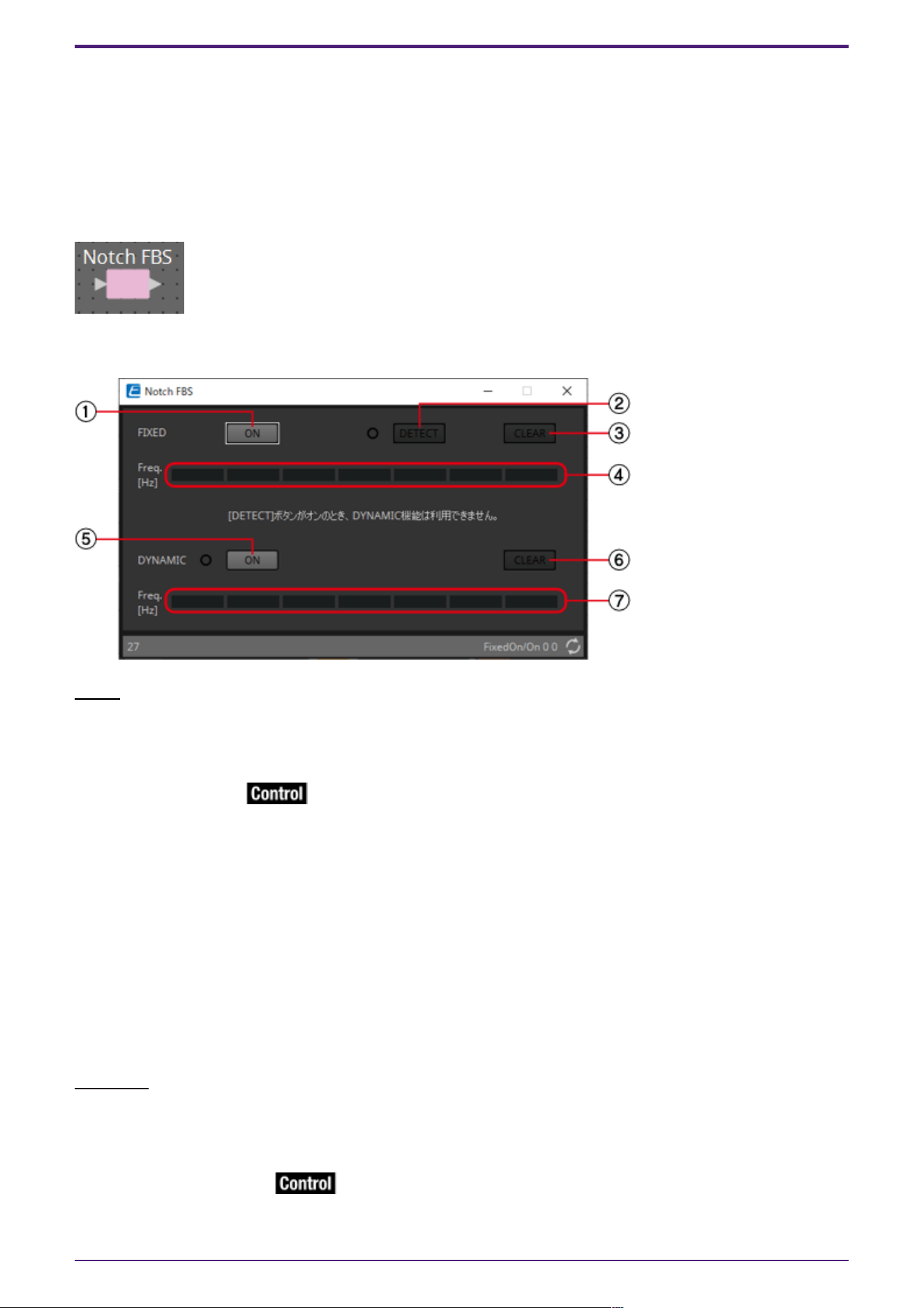
2.24. Feedback Suppressor: Notch FBS
The Feedback Suppressor (subsequently referred to as FBS) is a function that prevents the unpleasant
acoustic feedback that occurs when sound from a speaker is picked up by a mic and re-amplified. In
addition to being unpleasant, acoustic feedback places a strain on the speakers, and can damage them.
To prevent such feedback, place the speakers so that their sound will not be picked up by the mic and
amplified. If acoustic feedback still occurs, you can use FBS to improve the feedback margin.
Notch FBS uses a notch filter to lower the level of the feedback point.
2.24.1. “Notch FBS” component editor
FIXED
After the speakers and mics have been installed, and while the DME settings are being made, this
method proactively finds feedback points in the current sound system, and applies the appropriate
filters. This is effective for mics whose position is fixed.
① FIXED [ON] button
Switches the detection result between enabled and disabled.
② [DETECT] button
Starts or stops detection. This is available only when online. Detection does not end automatically.
During detection, the DYNAMIC filtering is disabled. For details on the detection procedure, refer to
Performing FBS detection for the FIXED type.
③ [CLEAR] button
Clears the filter settings.
④ [Freq.]
Displays the frequencies of the filters that were applied. Up to seven filters will be applied.
DYNAMIC
This method continually finds the changing feedback points while the DME unit is in use, and updates
the filter settings accordingly. This is effective for wireless mics whose location is not fixed, and
which can be used in a variety of positions.
⑤ DYNAMIC [ON] button
Enables or disables the DYNAMIC function. FBS operation will begin when you turn this on.
2. Audio Components
ProVisionaire Design Component Guide | 69

⑥ [CLEAR] button
Clears the filter settings.
⑦ [Freq.]
Displays the frequencies of the filters that were applied. Up to seven filters will be applied.
• The indicator will light when the following occurs.
◦ When a frequency is displayed
◦ When a currently-displayed frequency is rewritten
• When using FIXED, calculation will continue repeatedly even after all seven filters have been
displayed, for example to combine the frequencies that are closest to each other. However when
using DYNAMIC, if all seven filters are already displayed but new feedback is found, the filter
that was specified first and that will have the least effect on the audio quality will be
discarded, and replaced by the newly-specified filter. A filter will be discarded automatically
after a certain length of time has elapsed since it was applied.
• It is not possible to completely eliminate all feedback in all environments.
• If feedback increases when you raise a fader or the gain, and is not automatically suppressed,
lower the fader or gain to prevent the speakers from being damaged.
Performing FBS detection for the FIXED type
In order to obtain good results, you should set up the mics, speakers, and other sound equipment, and
adjust the output EQ settings before performing detection. If you want, FIXED can also be used in
conjunction with DYNAMIC.
1. Adjust the power amp output volume.
While vocalizing into the mic, gradually raise the power amp output to the volume at which the system
will be operated in actual use. In addition, clap your hands and verify that feedback does not occur.
2. Maintain silence in the space for which you want to suppress feedback.
3. Minimize the input of the mic that you want to detect.
To minimize the input, you can either adjust the input gain or use the fader to adjust the output. In
the components that you have placed, adjust the parameters of the appropriate component.
4. Click the [DETECT] button to begin detection.
5. Gradually raise the input of the mic that you want to detect.
Feedback will occur, but the DME will immediately detect that frequency and insert a filter.
Repeat this operation. When you have obtained a satisfactory result, click the [DETECT] button to end
detection.
If you don’t notice any result, it may be that detection has failed. Click the [CLEAR] button to
discard the detection result. If you want to make the settings once again, adjust the position of the
mics and speakers, adjust the volume, and try the above procedure once again from step 1. In some
cases, detection will not occur correctly if the overall volume is raised excessively, or if the mics and
speakers are too close, or if sound from a speaker is directly entering a mic.
The DME cannot detect multiple feedback points simultaneously. Slowly increasing the fader
and gain, etc. to allow the acoustic feedback to occur gradually will allow for appropriate results to be
obtained.
2. Audio Components
70 | ProVisionaire Design Component Guide

2.24.2. Control
Parameter types of the input/output values for each Port
Input Value Control Parameter Output Value
Type Range Input
Port
Name
Paramete
r Range
Output
Port
Name
Type Range
Value Num 0,1 ● Fixed
On
OFF:0,
ON:1
● Fixed
On
Value Num
OFF:0,
ON:1
Value Num 0,1 ●
Dynamic
On
OFF:0,
ON:1
●
Dynamic
On
Value Num
OFF:0,
ON:1
2. Audio Components
ProVisionaire Design Component Guide | 71
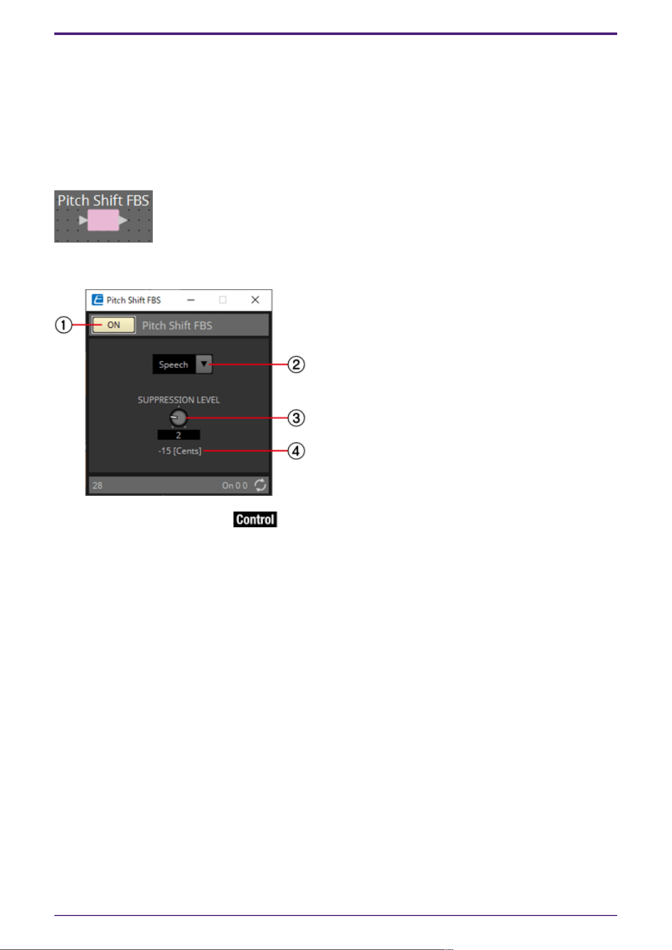
2.25. Feedback Suppressor: Pitch Shift FBS
The Feedback Suppressor (subsequently referred to as FBS) is a function that prevents the unpleasant
acoustic feedback that occurs when sound from a speaker is picked up by a mic and re-amplified. In
addition to being unpleasant, acoustic feedback places a strain on the speakers, and can damage them.
To prevent such feedback, place the speakers so that their sound will not be picked up by the mic and
amplified. If acoustic feedback still occurs, you can use FBS to improve the feedback margin.
Pitch Shift FBS slightly shifts the pitch of the frequency point that is feeding-back, thereby ending
the feedback loop.
2.25.1. “Pitch Shift FBS” component editor
① Pitch Shift FBS [ON] button
Switches the Pitch Shift FBS function between enabled and disabled. Pitch Shift FBS operation will
begin when you turn this on.
② Mode list box
Selects the type of input signal.
The modes are as follows.
•
Speech
Choose this if the input signal is speech.
•
Music
Choose this if the input signal is music.
③ [SUPPRESSION LEVEL] knob
Specifies the amount by which feedback is suppressed. Higher values produce a stronger effect.
④ [Cents]
Indicates the amount of pitch change applied by the effect, in units of cents.
2. Audio Components
72 | ProVisionaire Design Component Guide

2.25.2. Control
Parameter types of the input/output values for each Port
Input Value Control Parameter Output Value
Type Range Input
Port
Name
Paramete
r Range
Output
Port
Name
Type Range
Value Num 0,1 ● On
OFF:0,
ON:1
● On Value Num
OFF:0,
ON:1
2. Audio Components
ProVisionaire Design Component Guide | 73

2.26. Filter: BPF
A filter allows a specific frequency region to pass and attenuates other frequency regions.
The DME provides three types of filter: BPF (band-pass filter), HPF (high-pass filter), and LPF (low-
pass filter). Select either Mono, Stereo or Multi when you place this component in the design sheet.
The illustrations used in the following explanation are for the case of Stereo.
The filter attenuation amount and type can be selected from the [HPF] list box and the [LPF] list box
in each component editor.
The filter attenuation amount can be set to [6dB/Oct], [12dB/Oct], [18dB/Oct], [24dB/Oct],
[36dB/Oct] or [48dB/Oct]. Lower values apply more gentle attenuation; higher values apply steeper
attenuation.
Each type of filter is described below.
•
Thru
No filter will be applied. There will be no attenuation; the response will be the same at all
frequencies.
•
AdjustGc(Adjustable Gc)
The Gc knob will appear when you select this.
Adjusts the Gc (gain at the cutoff frequency) in a range of –6 to +6 dB. Setting this to –3 dB
will produce a Butterworth filter, and setting this to –6 dB will produce a Linkwitz-Riley filter.
•
Butrwrth (Butterworth)
This is the most common response. The passed region is flat, and the gain at the cutoff
frequency is –3 dB.
•
Bessel
This curve emphasizes the phase response; the attenuation is more gradual than Butterworth,
but the waveform will not be distorted when a square wave is passed through it.
•
Linkwitz (Linkwitz-Riley)
The order of this filter will be a power of two; the summed voltage of the LPF and HPF outputs
will produce a gain of 0 dB across the entire frequency range. The passed region is flat, and the
gain at the cutoff frequency is –6 dB.
2. Audio Components
74 | ProVisionaire Design Component Guide
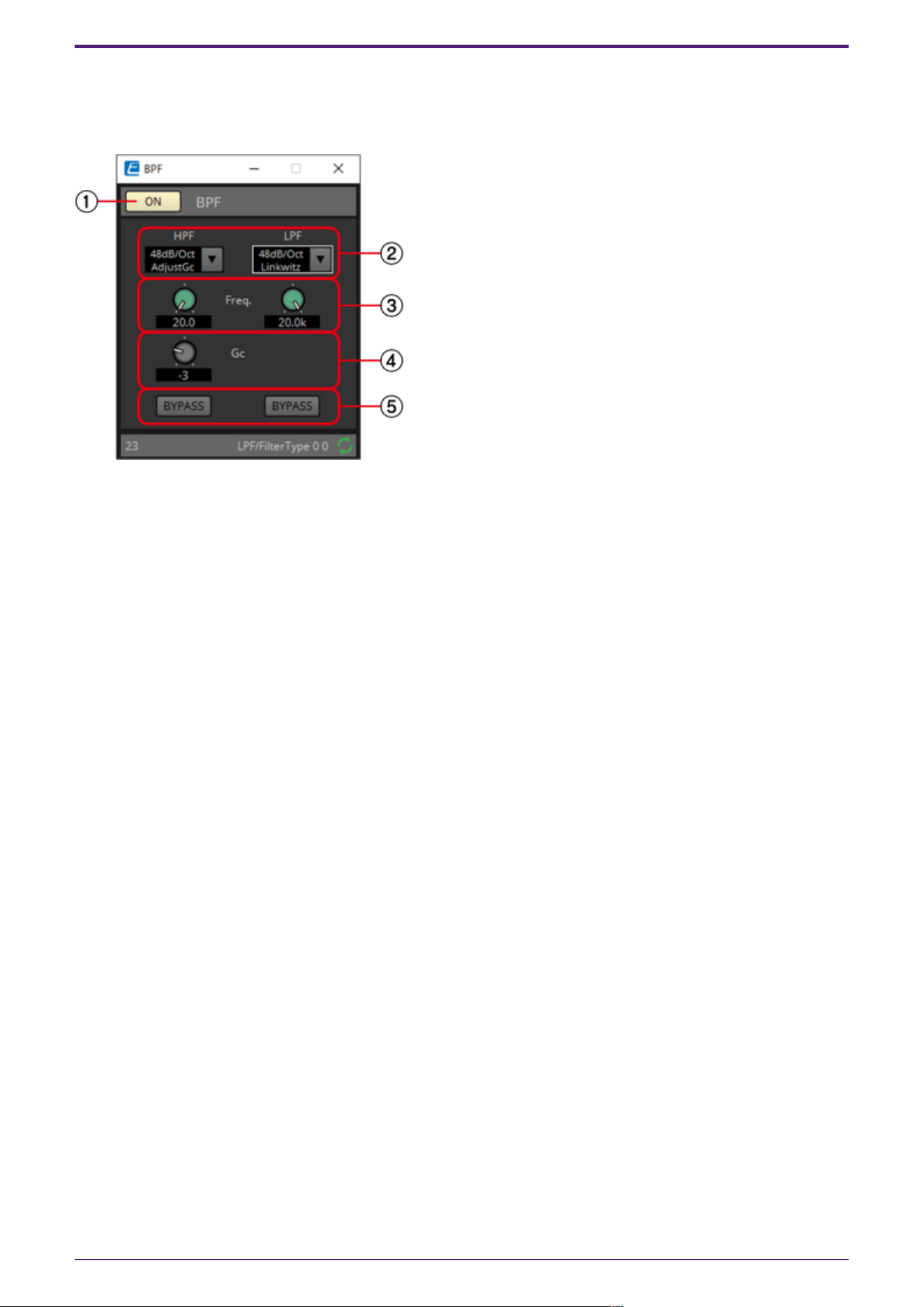
2.26.1. “BPF” component editor
This filter passes the signal in a specified frequency band, and attenuates the signal in other
frequency regions.
① BPF [ON] button
Enables or disables the BPF.
② [HPF]/[LPF] list box
Select the amount of attenuation per octave, and the type of filter.
③ [Freq.] knobs
Specify the cutoff frequency of the HPF and LPF.
④ [Gc] knob
When [AdjustGc] (Adjustable Gc) is selected in the [HPF]/[LPF] list box, these knobs specify the gain
at the cutoff frequency.
④ [BYPASS] buttons
Specify whether each band is bypassed. If you click a button to make it light, that filter is bypassed.
2.26.2. Control
There are no parameters that can be controlled through the Control layer.
2. Audio Components
ProVisionaire Design Component Guide | 75

2.27. Filter: HPF
A filter allows a specific frequency region to pass and attenuates other frequency regions.
The DME provides three types of filter: BPF (band-pass filter), HPF (high-pass filter), and LPF (low-
pass filter). Select either Mono, Stereo or Multi when you place this component in the design sheet.
The illustrations used in the following explanation are for the case of Stereo.
The filter attenuation amount and type can be selected from the [HPF] list box and the [LPF] list box
in each component editor.
The filter attenuation amount can be set to [6dB/Oct], [12dB/Oct], [18dB/Oct], [24dB/Oct],
[36dB/Oct] or [48dB/Oct]. Lower values apply more gentle attenuation; higher values apply steeper
attenuation.
Each type of filter is described below.
•
Thru
No filter will be applied. There will be no attenuation; the response will be the same at all
frequencies.
•
AdjustGc(Adjustable Gc)
The Gc knob will appear when you select this.
Adjusts the Gc (gain at the cutoff frequency) in a range of –6 to +6 dB. Setting this to –3 dB
will produce a Butterworth filter, and setting this to –6 dB will produce a Linkwitz-Riley filter.
•
Butrwrth (Butterworth)
This is the most common response. The passed region is flat, and the gain at the cutoff
frequency is –3 dB.
•
Bessel
This curve emphasizes the phase response; the attenuation is more gradual than Butterworth,
but the waveform will not be distorted when a square wave is passed through it.
•
Linkwitz (Linkwitz-Riley)
The order of this filter will be a power of two; the summed voltage of the LPF and HPF outputs
will produce a gain of 0 dB across the entire frequency range. The passed region is flat, and the
gain at the cutoff frequency is –6 dB.
2. Audio Components
76 | ProVisionaire Design Component Guide
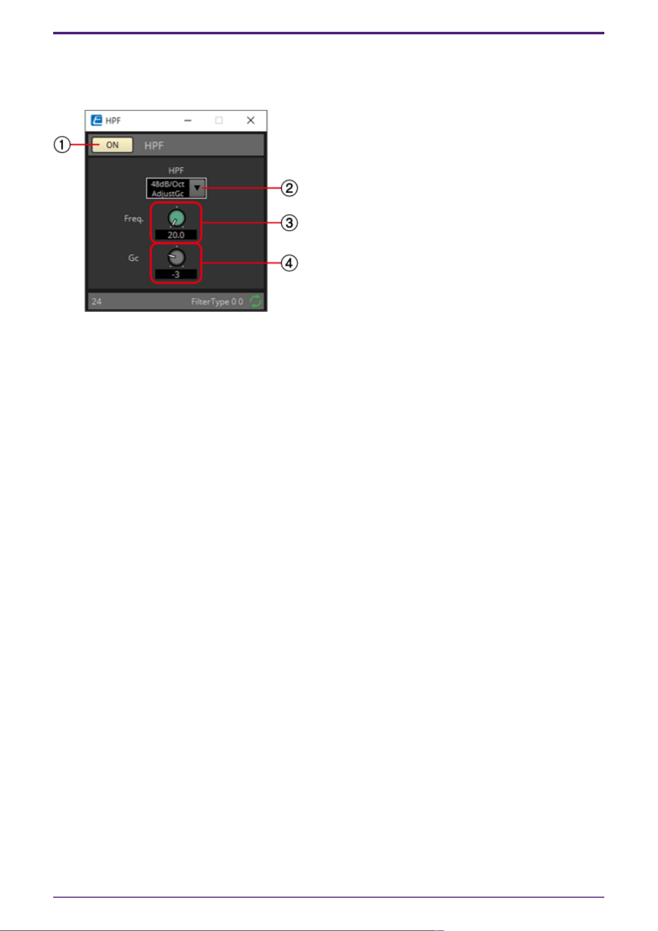
2.27.1. “HPF” component editor
This filter passes the signal of the region above the specified frequency, and attenuates the signal in
the lower frequency region.
① HPF [ON] button
Enables or disables the HPF.
② [HPF] list box
Selects the amount of attenuation per octave, and the type of filter.
③ [Freq.] knob
Specifies the cutoff frequency.
④ [Gc] knob
When [AdjustGc] (Adjustable Gc) is selected in the [HPF] list box, this knob specifies the gain at the
cutoff frequency.
2.27.2. Control
There are no parameters that can be controlled through the Control layer.
2. Audio Components
ProVisionaire Design Component Guide | 77

2.28. Filter: LPF
A filter allows a specific frequency region to pass and attenuates other frequency regions.
The DME provides three types of filter: BPF (band-pass filter), HPF (high-pass filter), and LPF (low-
pass filter). Select either Mono, Stereo or Multi when you place this component in the design sheet.
The illustrations used in the following explanation are for the case of Stereo.
The filter attenuation amount and type can be selected from the [HPF] list box and the [LPF] list box
in each component editor.
The filter attenuation amount can be set to [6dB/Oct], [12dB/Oct], [18dB/Oct], [24dB/Oct],
[36dB/Oct] or [48dB/Oct]. Lower values apply more gentle attenuation; higher values apply steeper
attenuation.
Each type of filter is described below.
•
Thru
No filter will be applied. There will be no attenuation; the response will be the same at all
frequencies.
•
AdjustGc(Adjustable Gc)
The Gc knob will appear when you select this.
Adjusts the Gc (gain at the cutoff frequency) in a range of –6 to +6 dB. Setting this to –3 dB
will produce a Butterworth filter, and setting this to –6 dB will produce a Linkwitz-Riley filter.
•
Butrwrth (Butterworth)
This is the most common response. The passed region is flat, and the gain at the cutoff
frequency is –3 dB.
•
Bessel
This curve emphasizes the phase response; the attenuation is more gradual than Butterworth,
but the waveform will not be distorted when a square wave is passed through it.
•
Linkwitz (Linkwitz-Riley)
The order of this filter will be a power of two; the summed voltage of the LPF and HPF outputs
will produce a gain of 0 dB across the entire frequency range. The passed region is flat, and the
gain at the cutoff frequency is –6 dB.
2. Audio Components
78 | ProVisionaire Design Component Guide
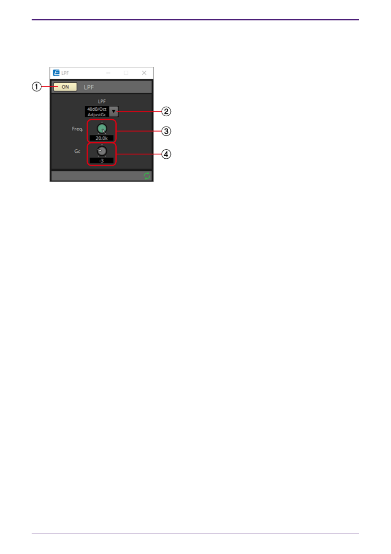
2.28.1. “LPF” component editor
This filter passes the signal of the region below the specified frequency, and attenuates the
signal in the upper frequency region.
① LPF [ON] button
Enables or disables the LPF.
② [LPF] list box
Selects the amount of attenuation per octave, and the type of filter.
③ [Freq.] knob
Specifies the cutoff frequency.
④ [Gc] knob
When [AdjustGc] (Adjustable Gc) is selected in the [LPF] list box, this knob specifies the gain at the
cutoff frequency.
2.28.2. Control
There are no parameters that can be controlled through the Control layer.
2. Audio Components
ProVisionaire Design Component Guide | 79
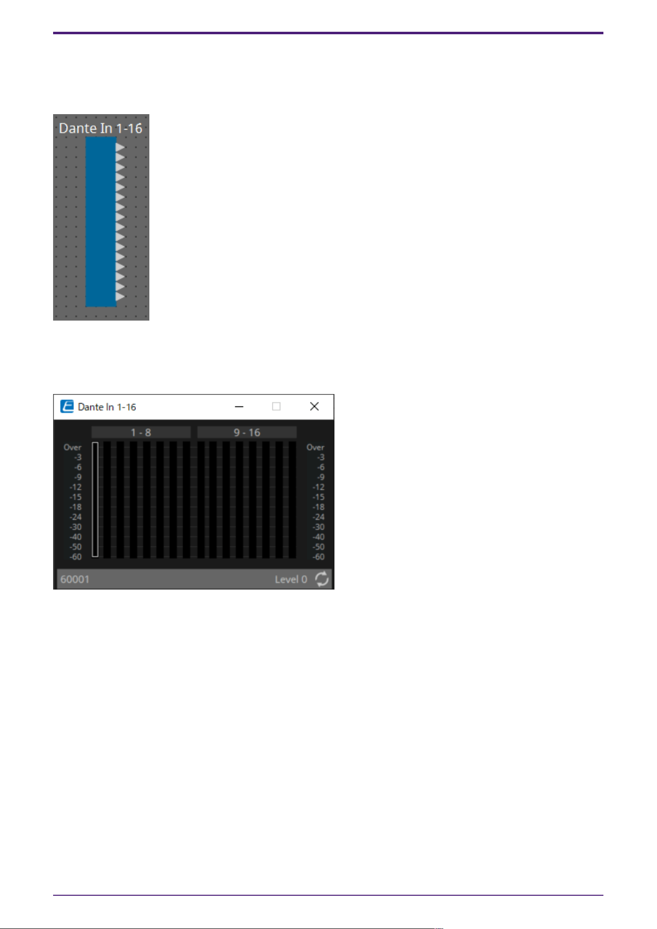
2.29. Input/Output: Dante In
This is the input jack of the DME.
The number of Dante Input channels is determined by the number of activated device licenses.
2.29.1. “Dante In” component editor
This shows the level of the audio signals that are being input from the Dante ports.
2.29.2. Control
There are no parameters that can be controlled through the Control layer.
2. Audio Components
80 | ProVisionaire Design Component Guide
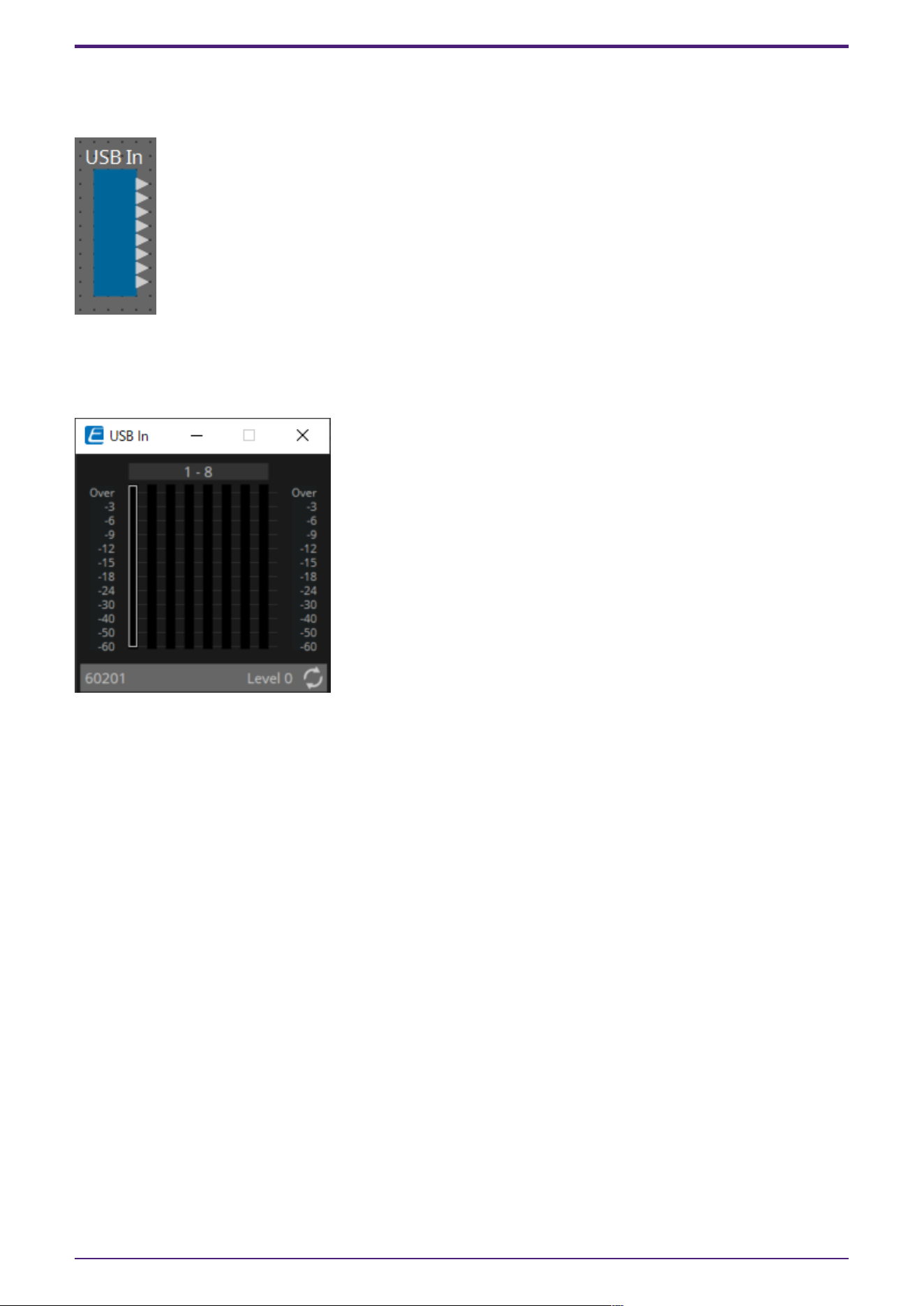
2.30. Input/Output: USB In
This is the input jack of the DME.
2.30.1. “USB In” component editor
This shows the level of the audio signals that are being input from the USB ports.
2.30.2. Control
There are no parameters that can be controlled through the Control layer.
2. Audio Components
ProVisionaire Design Component Guide | 81
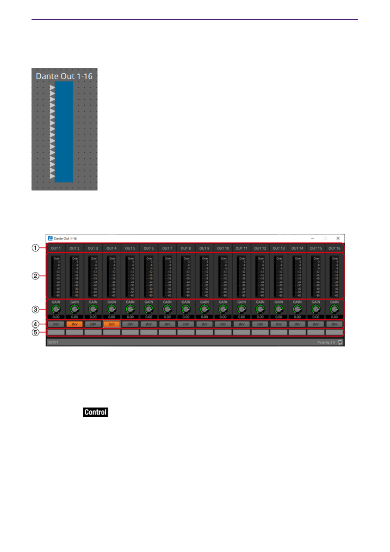
2.31. Input/Output: Dante Out
This is the output jack of the DME.
The number of Dante Output channels is determined by the number of activated device licenses.
2.31.1. “Dante Out” component editor
Here you can make settings related to Dante output.
① Channel index
Indicates the Dante channel number.
② Level meter
Indicates the analog output level.
③ [GAIN] knob
Adjusts the output gain.
④ [INV] button
Switches the polarity of the output signal.
⑤ Port name
Shows or edits the port name. This is linked with the “Label” of the component’s ports.
2. Audio Components
82 | ProVisionaire Design Component Guide

2.31.2. Control
Parameter types of the input/output values for each Port
Input Value Control Parameter Output Value
Type Range Input
Port
Name
Paramete
r Range
Output
Port
Name
Type Range
Value dB −∞–10.00 ● Gain
Out01
−∞–10.00 ● Gain
Out01
Value dB −∞–10.00
Normalized 0.00–1.00
2. Audio Components
ProVisionaire Design Component Guide | 83
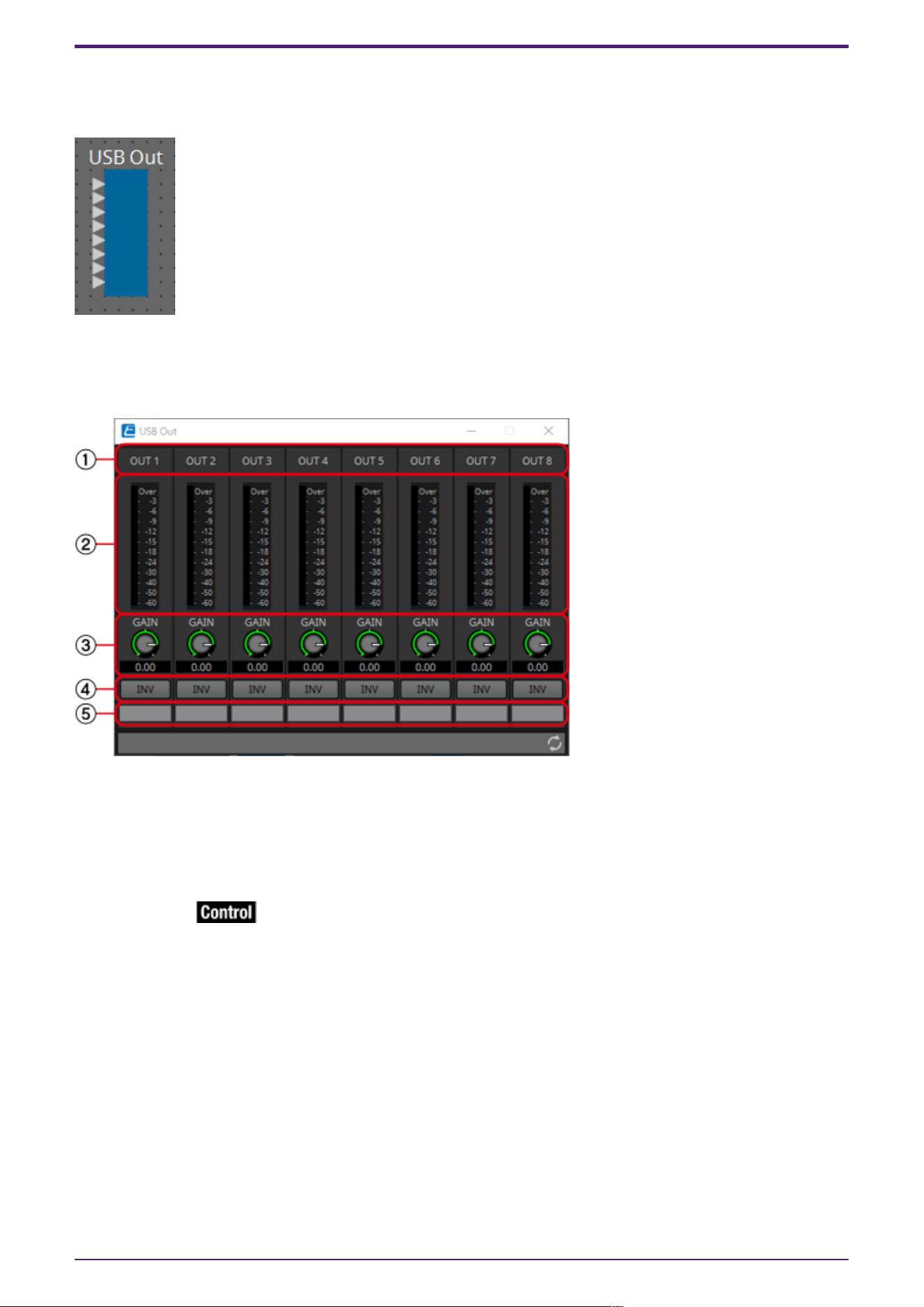
2.32. Input/Output: USB Out
This is the output jack of the DME.
2.32.1. “USB Out” component editor
Here you can make settings related to USB output.
① Channel index
Indicates the USB channel number.
② Level meter
Indicates the analog output level.
③ [GAIN] knob
Adjusts the output gain.
④ [INV] button
Switches the polarity of the output signal.
⑤ Port name
Shows or edits the port name. This is linked with the “Label” of the component’s ports.
2. Audio Components
84 | ProVisionaire Design Component Guide

2.32.2. Control
Parameter types of the input/output values for each Port
Input Value Control Parameter Output Value
Type Range Input
Port
Name
Paramete
r Range
Output
Port
Name
Type Range
Value dB −∞–10.00 ● Gain
Out01
−∞–10.00 ● Gain
Out01
Value dB −∞–10.00
Normalized 0.00–1.00
2. Audio Components
ProVisionaire Design Component Guide | 85
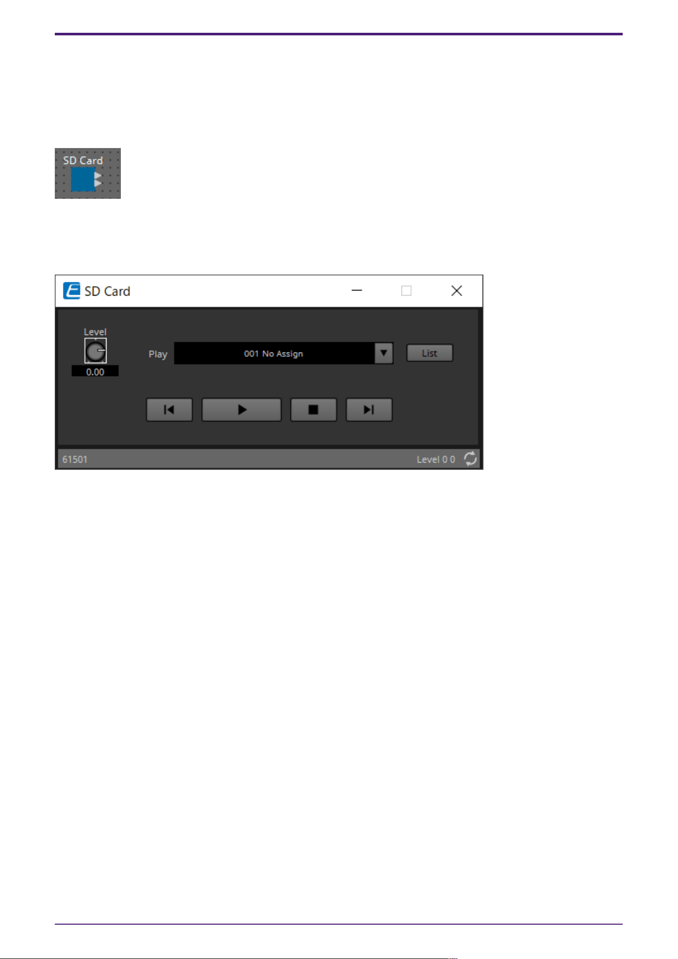
2.33. Input/Output: SD Card
By using commercially available SD memory cards, the DME can play music, sound effects, and other
audio files. The DME can play MP3 and WAV audio file formats. To play audio files stored on an SD
memory card, the SD Card component editor must be set.
If you want to output audio from an SD card, place an SD Card component.
2.33.1. ”SD Card” component editor
Selects, plays, and adjusts the volume of audio files.
Clicking on the [List] button opens the SD Card File Manager dialog box.
2. Audio Components
86 | ProVisionaire Design Component Guide
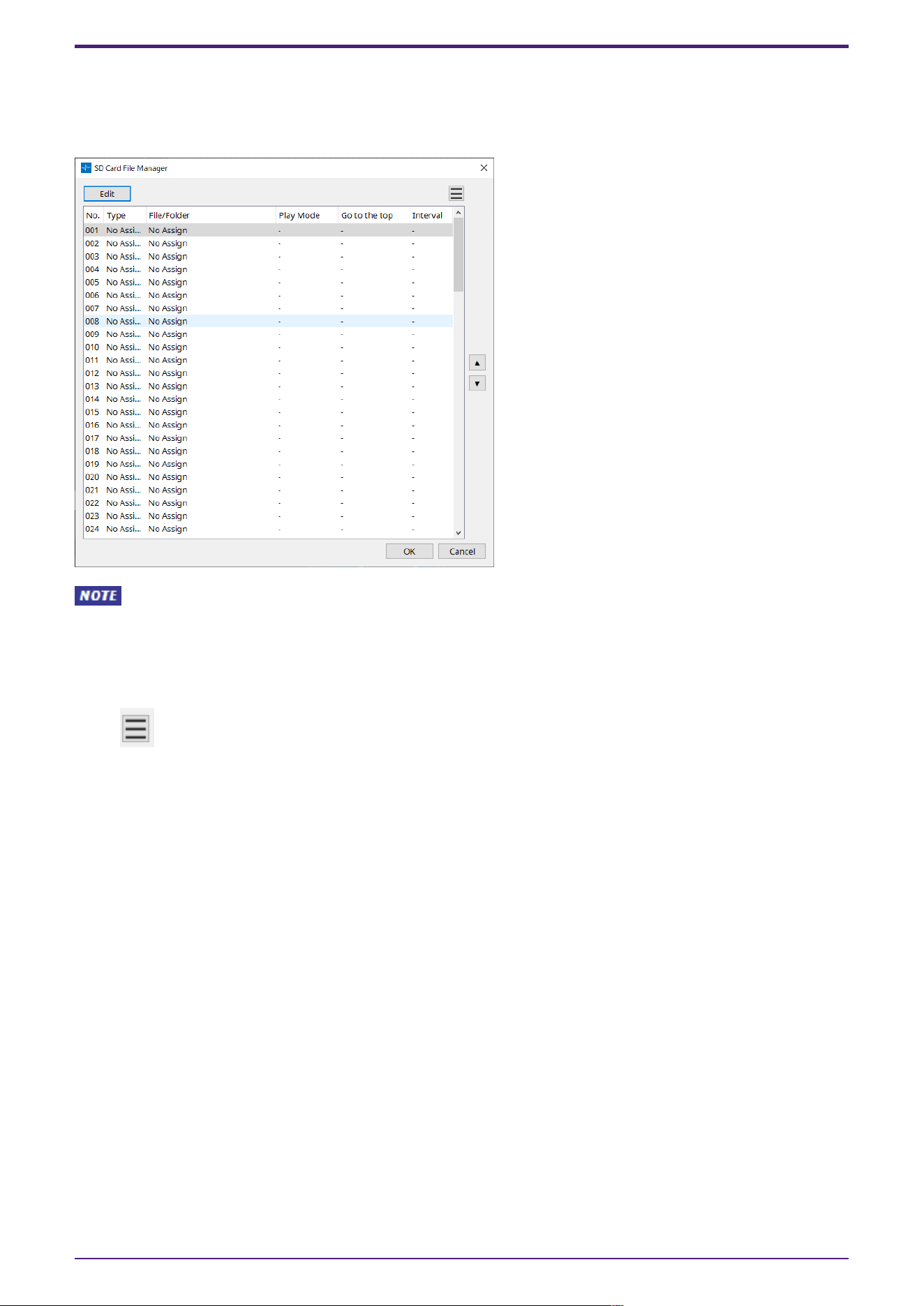
2.33.2. “SD Card File Manager” dialog box
This dialog box enables you to register a file you wish to play with the SD Card component.
The list in this dialog box is also used to play files via the DCP or GPI.
This screen can also be opened by clicking on the [Tools] button on the DME design sheet then
clicking [SD Card File Manager].
[Edit] button
Click this button to open the “SD Card File Settings” dialog box.
Menu button
Click this button to open the following context menu.
•
Copy
Copies the settings for the currently-selected row.
•
Paste
Pastes the copied contents to the currently-selected row or to the “SD Card File Manager”
dialog box for other devices.
•
Clear
Deletes the settings for the currently-selected row.
•
Copy All
Copies all settings.
•
Clear All
Deletes all settings.
List
If no file or folder is specified, “No Assign” appears.
•
No
You can set from row 001 up to row 100.
•
Type
2. Audio Components
ProVisionaire Design Component Guide | 87

If you selected “Play 1 Song” for “File/Folder” in the “Settings” dialog box, “1 Song” will appear
in this column. If you selected “Play all songs in a folder,” “Folder” will appear in this column.
•
File/Folder
Indicates the file name or folder name.
•
Play Mode
Indicates the specified Play Mode.
•
Go to the top
Indicates the setting that was specified in the [Go to the top when playback stops] check box.
•
Interval
Indicates the interval time.
Up and down arrow buttons
Change the position of the currently-selected row.
[OK] button
Saves the settings and closes the dialog box.
[Cancel] button
Closes the dialog box without saving the settings.
2. Audio Components
88 | ProVisionaire Design Component Guide
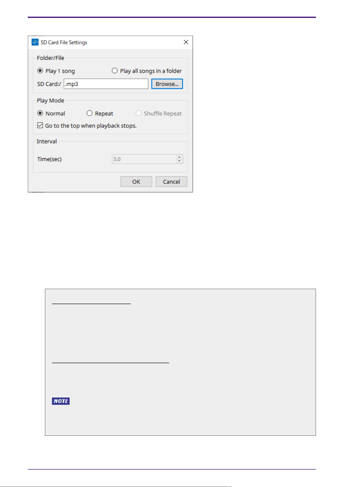
2.33.3. “SD Card File Settings” dialog box
[Folder/File]
Specifies the file to play.
•
[Play 1 song] / [Play all songs in a folder] option button
If you choose [Play 1 song], only the file currently selected in [SD CARD:/] will play.
If you select [Play all songs in a folder], all files saved in the folder selected by [SD CARD:/] will
play.
•
[SD CARD:/]
This shows the name of the file or folder that will be played. You can change the name, or enter
it directly.
If [Play 1 song] is selected
The following file and folder formats can be shown.
• (folder name)\(file name).mp3
• (folder name)\(file name).wav
• (file name).mp3
• (file name).wav
If [Play all songs in a folder] is selected
The following folder formats can be shown.
• (folder name)
• blank
・Only first-level folders are valid.
・If the folder name is blank, the songs that exist in the root level of the memory card will
be played (folders below the root level will not be included).
2. Audio Components
ProVisionaire Design Component Guide | 89
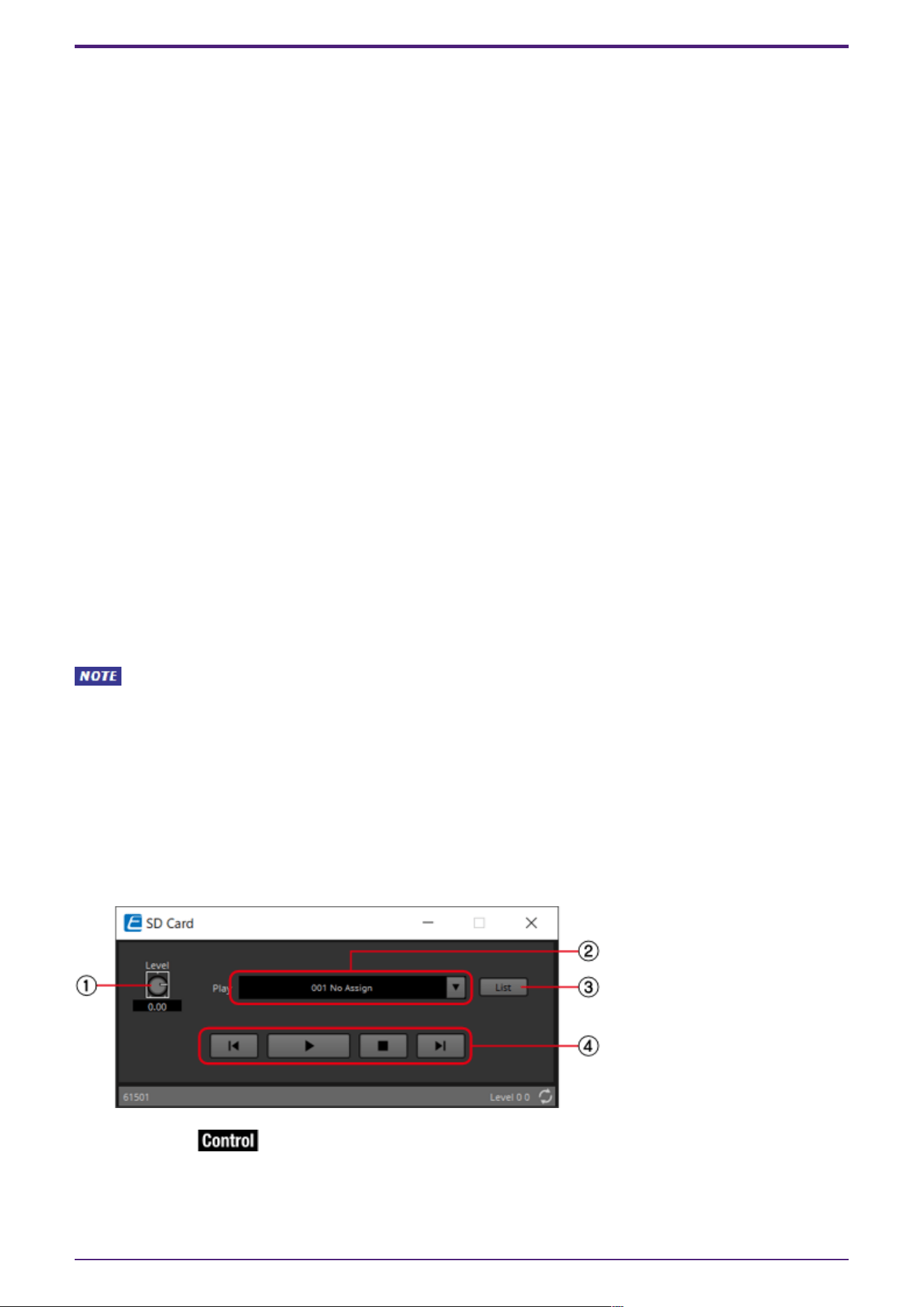
•
[Browse] button
When you click this, a screen will appear, allowing you to select the file or folder to be played.
If you choose [Play 1 song], select a file.
If you choose [Play all songs in a folder], select a folder.
[Play Mode]
•
[Normal]/[Repeat]/[Shuffle Repeat]
This specifies the play mode for the file or files.
If you choose [Normal], the specified file or files in the folder will play once.
If you choose [Repeat], the specified file or files in the folder will play repeatedly.
If you choose [Shuffle Repeat], the files in the specified folder will play repeatedly in random
order. If you choose [Play 1 song] in [Folder/File], the [Shuffle Repeat] setting will be
unavailable.
•
[Go to the top when playback stops.] check box
When you stop file playback, this specifies whether the file will pause at the location where you
stopped or will return to the beginning of the file.
If this is On, playback will begin from the beginning of the file or the first file in the folder the
next time you start playback.
If this is Off, playback will begin from the location at which you stopped the next time you start
playback.
[Interval]
This specifies the playback spacing when files are played consecutively.
•
Time(sec)
You can set the time in the range from 0.0 sec to 10.0 sec in 0.1 sec steps.
If an event to play another file is executed while the current file is still playing, the current
playback will stop and the other file will start to play.
[OK] button
Saves the settings and closes the dialog box.
[Cancel] button
Closes the dialog box without saving the changes.
After registering files to be played, use the SD Card component editor to select and play audio files
and to adjust volume.
① [Level] knob
Adjusts the volume.
2. Audio Components
90 | ProVisionaire Design Component Guide
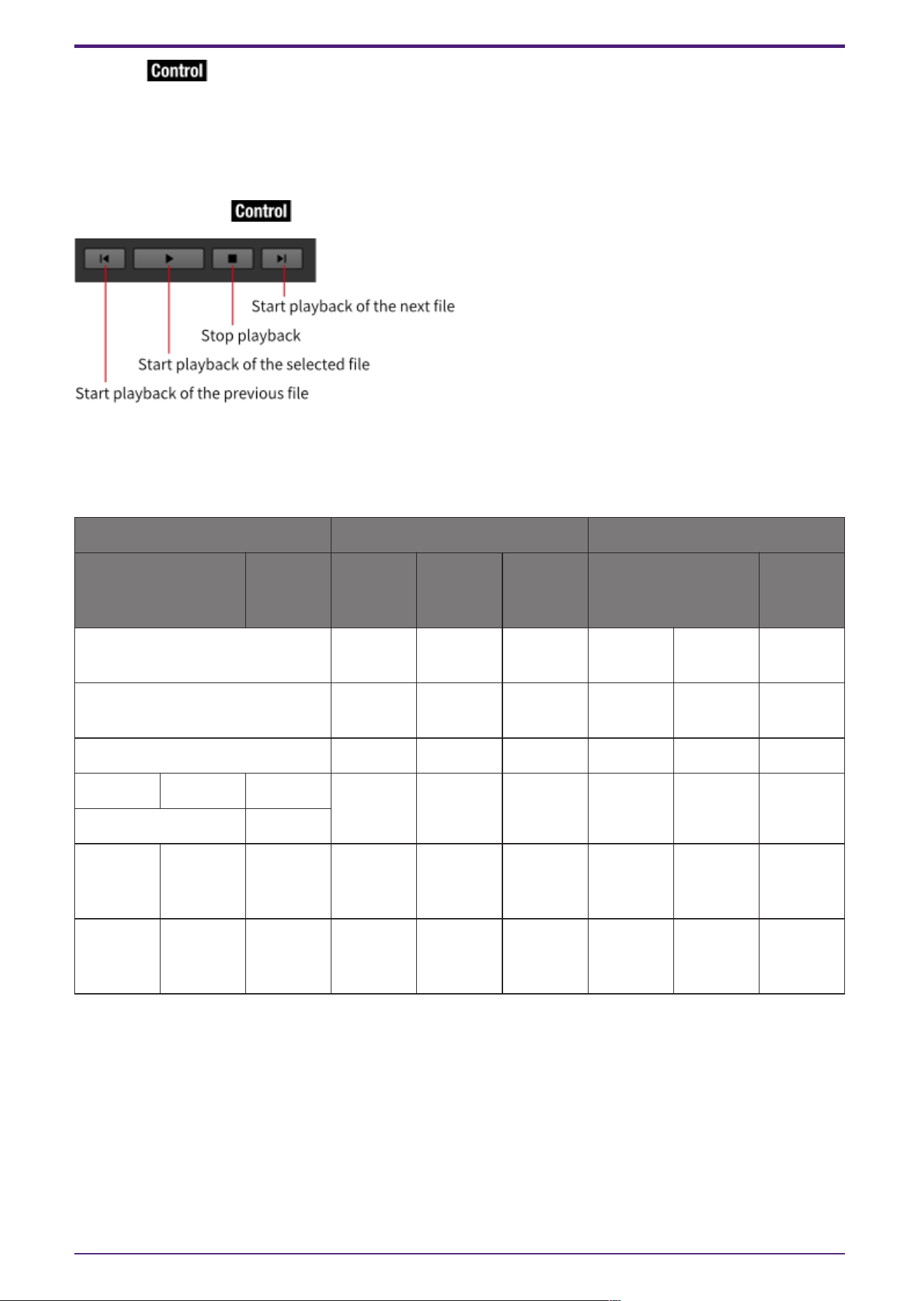
② [Play]
A drop-down list is displayed when clicked, and the files registered in the SD Card File Manager can be
selected.
③ [List] button
Opens the “SD Card File Manager” dialog.
④ Playback Control
2.33.4. Control
Parameter types of the input/output values for each Port
Input Value Control Parameter Output Value
Type Range Input
Port
Name
Paramete
r Range
Output
Port
Name
Type Range
Any Trigger ● File
001
Start - - - -
Any Trigger ●
Play/Stop
Play Stop - - - -
Any Trigger ● Stop Stop - - - -
Value dB −∞–10.00 ● Level −∞–10.00 ● Level Value dB −∞–10.00
Normalized 0.00–1.00
Value Num 1,2… ●
Sel&Play
1:File1Sta
rt 2:File2
Start …
- - - -
- - - - 0:Stop
1:During
playback
● Status Value Num 0:Stop
1:During
playback
2. Audio Components
ProVisionaire Design Component Guide | 91
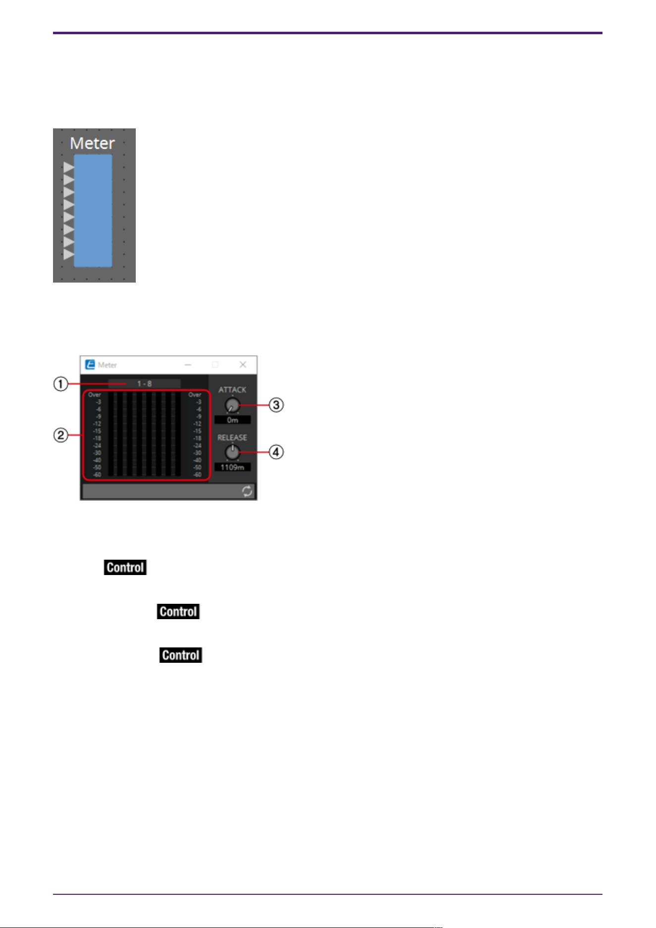
2.34. Meter
This displays the signal level of each channel.
Specify the number of channels when you place this component in the design sheet. The illustration
used in the following explanation is for the case of eight channels.
2.34.1. ”Meter” component editor
This displays the output level of each channel.
① Channel index
Channel numbers are shown in units of eight channels.
② Meter
This displays the signal level of each channel.
③ [ATTACK] knob
Specifies the attack time (the speed of input signal rise).
④ [RELEASE] knob
Specifies the release time (the speed of input signal drop).
2. Audio Components
92 | ProVisionaire Design Component Guide
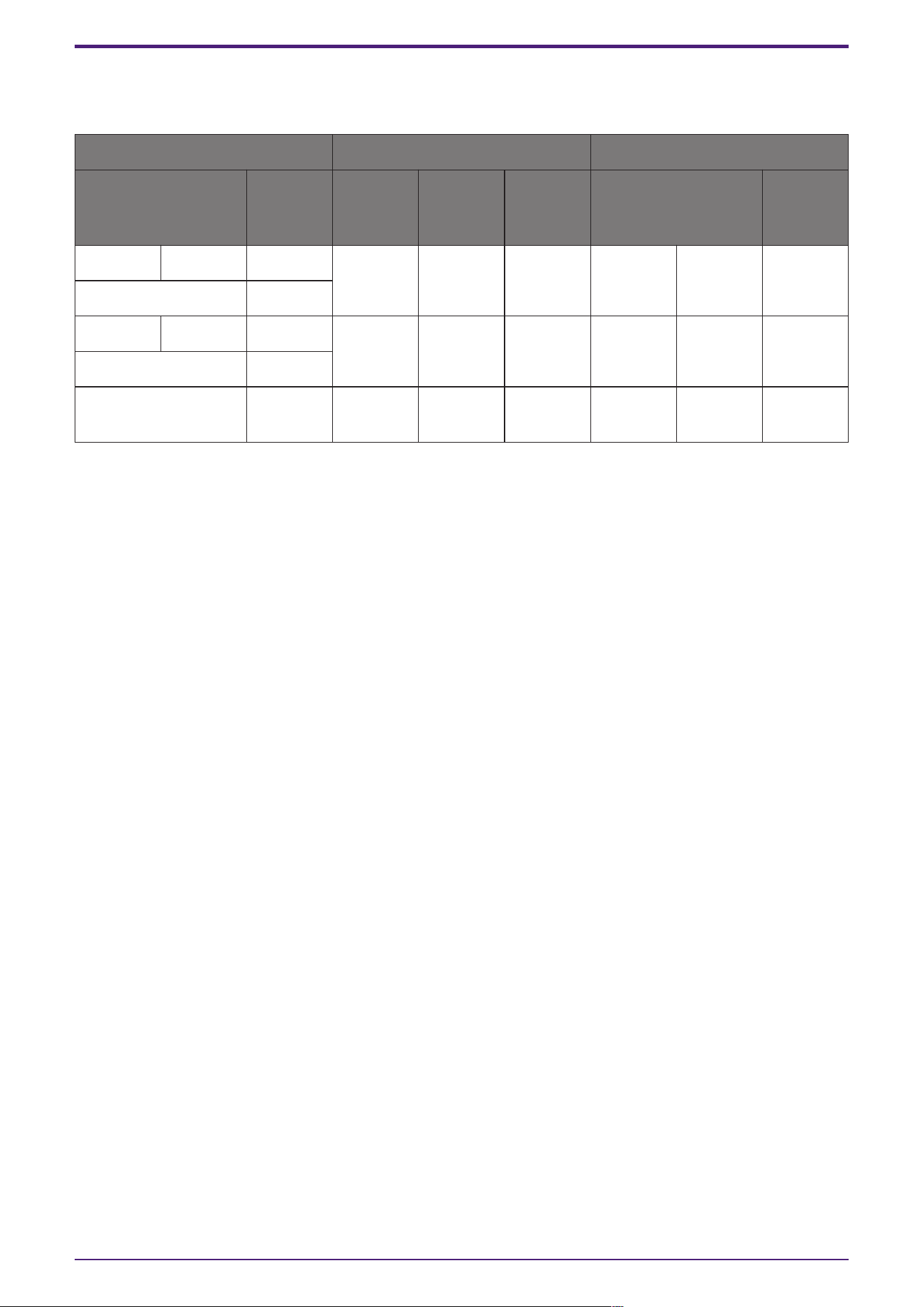
2.34.2. Control
Parameter types of the input/output values for each Port
Input Value Control Parameter Output Value
Type Range Input
Port
Name
Paramete
r Range
Output
Port
Name
Type Range
Value dB −∞–10.00 ● Attack −∞–10.00 ● Attack Value dB −∞–10.00
Normalized 0.00–1.00
Value dB −∞–10.00 ●
Release
−∞–10.00 ●
Release
Value dB −∞–10.00
Normalized 0.00–1.00
- - - −∞–10.00 ● Meter
Ch1
Value dB −∞–10.00
2. Audio Components
ProVisionaire Design Component Guide | 93
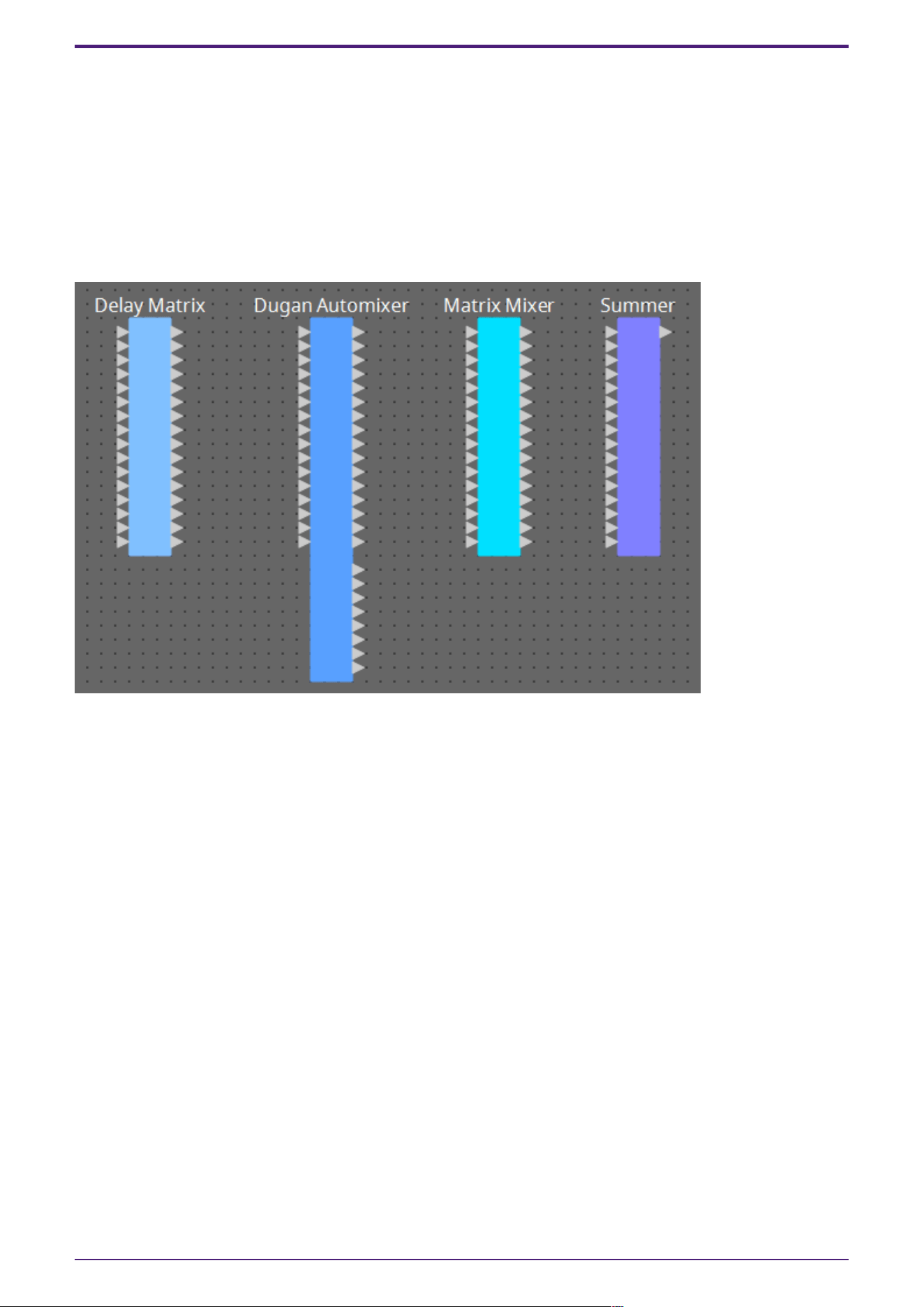
2.35. Mixer: Delay Matrix, Matrix Mixer
The DME provides four types of mixers: Delay Matrix, Dugan Automixer, Matrix Mixer, and Summer.
When placing this component in the design sheet, select the number of channels. The maximum number
of inputs and outputs for the Delay Matrix is 64-in/128-out. The maximum number of inputs for the
Dugan Automixer is 64 channels. The maximum number of inputs and outputs for the Matrix Mixer is
256-in/256-out. The maximum number of Summer inputs and outputs is 32-in/1-out. Since the Summer
simply mixes and outputs the input audio, it has no component editor. The illustration used in the
following explanation is for the case of 16 channels.
The number of Dante Input/Output channels is determined by the number of activated device licenses.
Starting from the top, the Dugan Automixer has the following outputs.
Discrete Out (processed sound) × number of mics
Group Mix Out (the mixed sound of each group) × number of groups
2. Audio Components
94 | ProVisionaire Design Component Guide
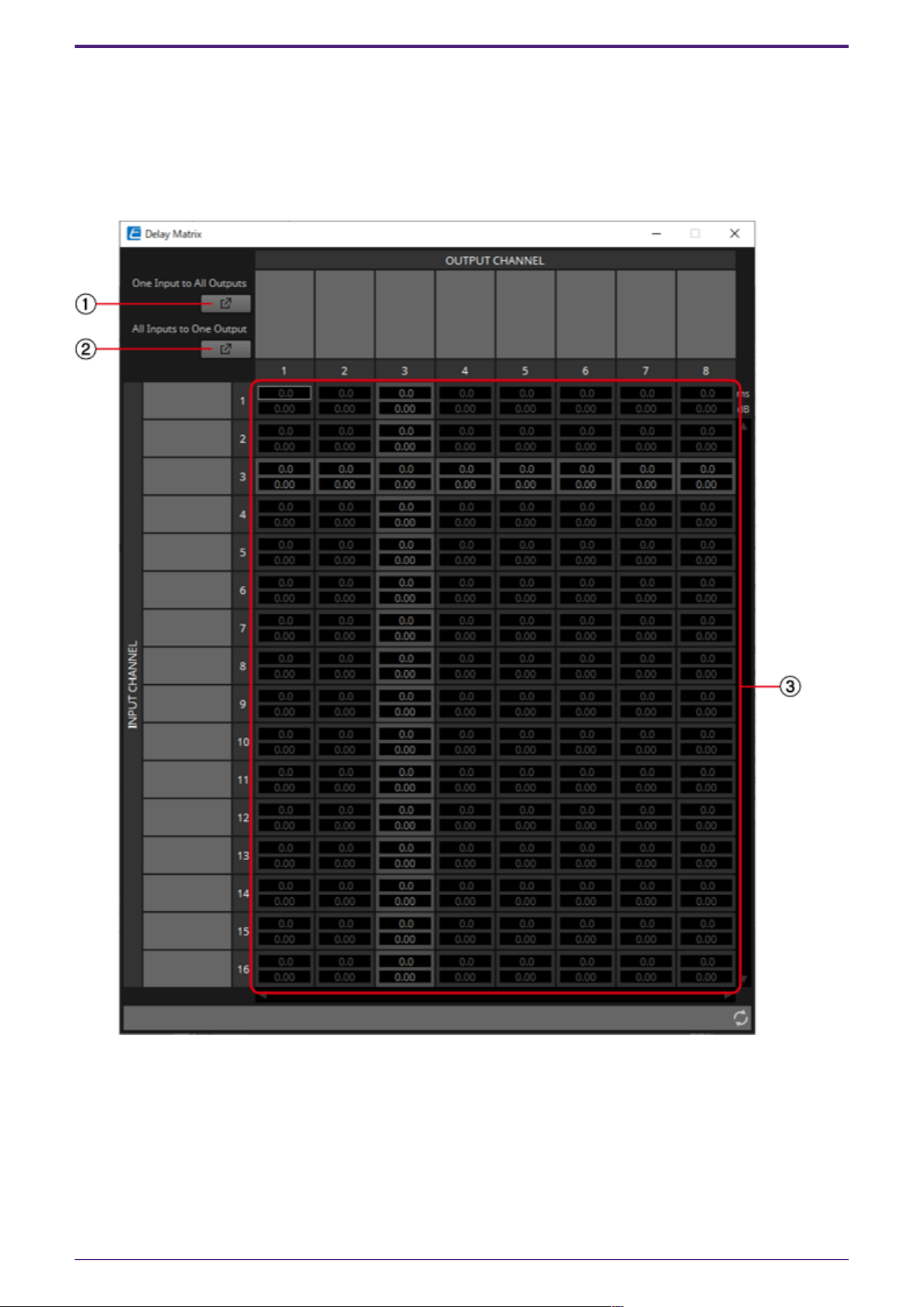
2.35.1. “Delay Matrix” component editor / “Matrix Mixer” component
editor
This mixer places the input channels and output buses in a matrix. In the “Matrix Mixer” component
editor you can adjust the group balance for each output bus. In the “Delay Matrix” component editor
you can adjust the group balance and delay for each output bus.
Here we explain using a screenshot of the “Delay Matrix” component editor.
① [One Input to All Outputs] window open button
Opens the “One Input to All Outputs” window. One input channel and the send levels from the input
channel to all output buses are displayed.
② [All Inputs to One Output] window open button
Opens the “All Inputs to One Output” window. One output channel and the send levels from each input
channel to the output bus are displayed.
2. Audio Components
ProVisionaire Design Component Guide | 95
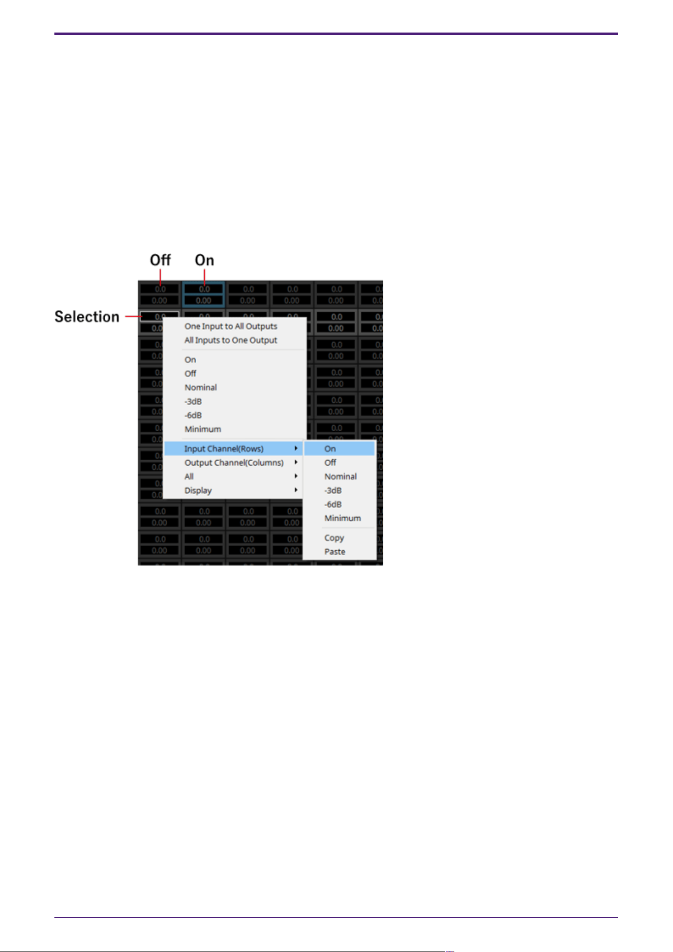
③ Channel matrix
Shows the send level and delay for each channel. The vertical axis shows the input channel, and the
horizontal axis shows the output channel. A cross-point is displayed when the cursor is placed over
this. It changes to selection mode when clicked. Press the up/down arrow keys or hold down the left
mouse button and move up or down to change the value. The numeric value can also be entered directly
by double clicking. Press the <Tab> key to move right.
When you double-click a port name display area located above or to the left of the matrix, a window
opens, allowing you to edit the name of the port.
Right-clicking on a cross-point allows the cross-point to be set on or off, the send level to be set, as
well as the ability to turn the horizontal or vertical axis with the cross-point on or off and setting its
send level. The settings of a horizontal/vertical axis can be copy & pasted to another
horizontal/vertical axis, or the display can be changed to a bar graph. The following choices are
provided.
•
[One Input to All Outputs]
Opens the One Input to All Outputs window.
•
[All Inputs to One Output]
Opens the All Inputs to One Output window.
•
[On]
Turns the cross-point ON.
•
[Off]
Turns the cross-point OFF.
•
[Nominal]
Sets the cross-point’s send level to 0 dB.
•
[-3dB]
Sets the cross-point send level to –3 dB.
•
[-6dB]
Sets the cross-point send level to –6 dB.
•
[Minimum]
Sets the cross-point send level to −∞ dB.
2. Audio Components
96 | ProVisionaire Design Component Guide
• [Input Channel(Rows)]
◦ This is the setting for the horizontal axes of the matrix.
◦ On: Turn all of the horizontal axes ON.
◦ Off: Turn all of the horizontal axes OFF.
◦ Nominal/–3 dB/–6 dB/Minimum: Sets the horizontal axis send level to Nominal, –3 dB, –6
dB, or Minimum.
◦ Copy: Copies the horizontal axis settings (both delay time and send level).
◦ Paste: Pastes the copied contents into a different horizontal axis.
• [Output Channel(Columns)]
◦ This is the setting for the vertical axes of the matrix.
◦ On: Turn all of the vertical axes ON.
◦ Off: Turn all of the vertical axes OFF.
◦ Nominal/–3 dB/–6 dB/Minimum: Sets the vertical axis send level to Nominal, –3 dB, –6 dB,
or Minimum.
◦ Copy: Copies the vertical axis settings (both delay time and send level).
◦ Paste: Pastes the copied contents into a different vertical axis.
•
[All]
Either turns all sends OFF, or sets all send levels to ‒∞ dB (Minimum).
•
[Display]
The display can be changed to a bar graph. The upper limit for the display can be selected from
50 ms/250 ms/500 ms/1000 ms.
2. Audio Components
ProVisionaire Design Component Guide | 97
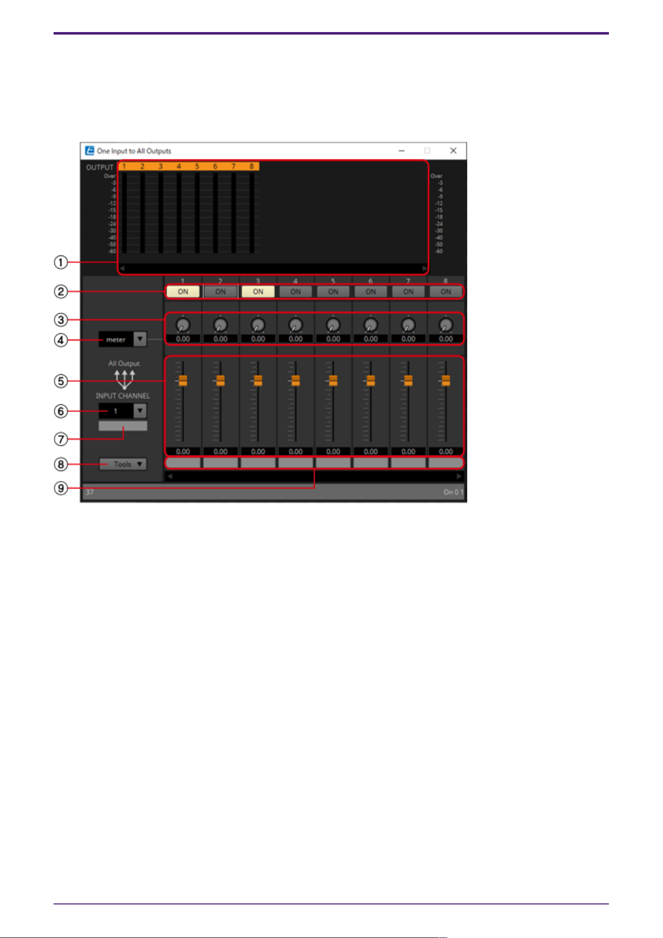
2.35.2. “One Input to All Outputs” window
One input channel and the send levels from the input channel to all output buses are displayed.
This window opens when you click the [One Input to All Outputs] window open button of the “Delay
Matrix” component editor or the “Matrix Mixer” component editor. Here we explain using a screenshot
of the “Delay Matrix - One Input to All Outputs” window.
① Meter
Shows the signal level for each output channel.
If there are many channels, a scroll bar will be displayed at the bottom.
② [ON] button
Switches the send from the input channel to each output bus either on or off.
③ Delay Time knob (“Delay Matrix” only)
Specifies the delay time from the input channel to each output bus. You can select the units in the
Type list box.
④ Type list box (“Delay Matrix” only)
The delay time specified by the Delay Time knob is converted into the units you select.
• ms………. Milliseconds
• sample…… Number of samples (The range will depend on the sampling frequency setting.)
• meter……. Meters/second
• feet…….. Feet/second
⑤ Fader
Adjusts the send level from the input channel to each output bus.
If there are many channels, a scroll bar will be displayed at the bottom.
2. Audio Components
98 | ProVisionaire Design Component Guide
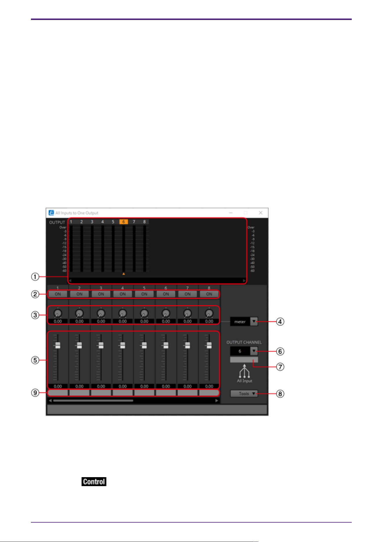
⑥ [INPUT CHANNEL] list box
Switches the input channel for which to make settings.
⑦ Input port name
Shows or edits the input port name.
This is linked with the “Label” of the component’s ports.
⑧ [Tools]
Sets the send level from the input channel to [On], [Off], [Nominal], [–3 dB], [–6 dB], or [Minimum].
⑨ Output port name
Shows or edits the output port name.
This is linked with the “Label” of the component’s ports.
2.35.3. “All Inputs to One Output” window
One output channel and the send levels from each input channel to the output bus are displayed.
This window opens when you click the [All Inputs to One Output] window open button of the “Delay
Matrix” component editor or the “Matrix Mixer” component editor. Here we explain using a screenshot
of the “Delay Matrix - All Inputs to One Output” window.
① Meter
Shows the signal level for each output channel. Below the meter, a ▲ symbol indicating the currently
selected output channel is shown. To select the output channel, you can either click the number or
select it from the OUTPUT CHANNEL list box.
If there are many channels, a scroll bar will be displayed at the bottom.
② [ON] button
Switches the send from each input channel to the output bus either on or off.
2. Audio Components
ProVisionaire Design Component Guide | 99
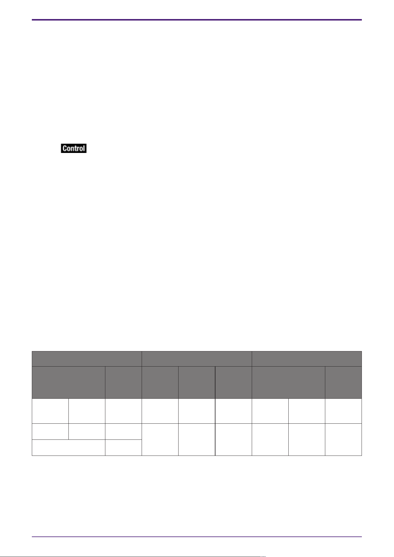
③ Delay Time knob (“Delay Matrix” only)
Specifies the delay time from each input channel to the output bus. You can select the units in the
Type list box.
④ Type list box (“Delay Matrix” only)
The delay time specified by the Delay Time knob is converted into the units you select.
• ms………. Milliseconds
• sample…… Number of samples (The range will depend on the sampling frequency setting.)
• meter……. Meters/second
• feet…….. Feet/second
⑤ Fader
Specifies the send level from each input channel to the output bus.
If there are many channels, a scroll bar will be displayed at the bottom.
⑥ [OUTPUT CHANNEL] list box
Switches the output channel being set.
⑦ Output port name
Shows or edits the output port name.
This is linked with the “Label” of the component’s ports.
⑧ [Tools]
Sets the send level from all input channels to [On], [Off], [Nominal], [–3 dB], [–6 dB], or [Minimum].
⑨ Input port name
Shows or edits the input port name.
This is linked with the “Label” of the component’s ports.
2.35.4. Control
Delay Matrix / Matrix Mixer
Parameter types of the input/output values for each Port
Input Value Control Parameter Output Value
Type Range Input
Port
Name
Paramete
r Range
Output
Port
Name
Type Range
Value Num 0,1 ● Out1
On In 1
OFF:0,
ON:1
● Out1
On In 1
Value Num
OFF:0,
ON:1
Value dB −∞–10.00 ● Out1
SendLevel
In 1
−∞–10.00 ● Out1
SendLevel
In 1
Value dB −∞–10.00
Normalized 0.00–1.00
2. Audio Components
100 | ProVisionaire Design Component Guide
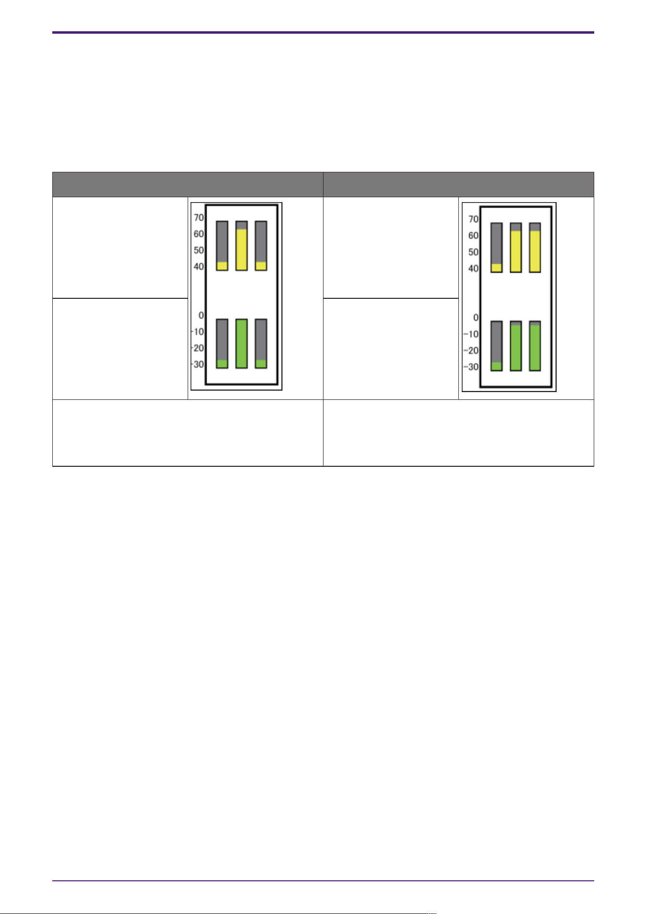
2.36. Mixer: Dugan Automixer
In a system used for unscripted speech, the automixer detects the mics that are in use and
automatically optimizes the gain distribution, maintaining a consistent system gain between multiple
mics without requiring an engineer to be constantly adjusting the faders.
The Dugan Automixer provided on the DME can automatically adjust the automix gain for up to 64 mics
used for speech.
In this explanation, we describe using the Dugan Automixer with three mics.
When one person is speaking When two people are speaking
Mic input audio (dB) Mic input audio (dB)
Automix gain (dB) Automix gain (dB)
When one person speaks, the gain of that mic
instantly rises, and the gain of the other mics
decreases. The same thing happens when a
different person speaks.
When two people speak simultaneously, the gain is
automatically distributed between the two mics
so that the total gain remains constant, and the
gain of the remaining mic decreases.
The Dugan Automixer differs from the functionality of a limiter or an auto level controller. When
multiple people are speaking, the engineer can use the faders to adjust individual levels as usual. Even
when nobody is speaking, the mic audio level is detected and the gain is distributed automatically, so
the faders can be left raised.
2. Audio Components
ProVisionaire Design Component Guide | 101
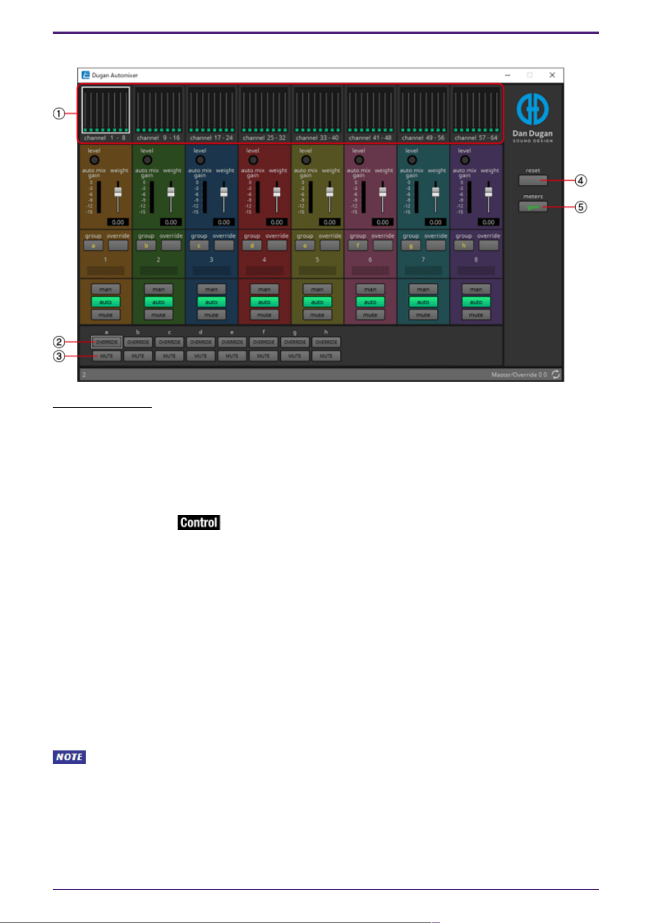
2.36.1. “Dugan Automixer” component editor
Main control field
① Channel display
For input channels 1–8, 9–16, 17–24, 25–32, 33–40, 41–48, 49–56, and 57–64, this area shows each
channel’s automix gain (Automix gain) meter and the man (yellow) / auto (green) / mute (red) status.
When you select the region of channels 1–8, 9–16, … or 57–64, the channels displayed in the channel
control field switch between 1–8, 9–16, … and 57–64.
② [OVERRIDE] button
This function instantly mutes all mics except for a specific mic, such as the mic of the chair or head.
If this is on, channels whose [override] button is on are set to “man,” and channels whose [override]
button is off are set to “mute.”
For the specified mic, such as of the chair or head, click the [override] button in the channel strip to
make it light yellow. Press the button once again to return to the previous setting.
③ [MUTE] button
Turns mute on/off for all mics in the group.
④ [reset] button
Resets the various parameters to their default values.
⑤ [meters] button
Switches the meter display of the channel control field between gain/input/output.
When using [weight] to adjust the relative sensitivity between the input channels, switching
the meter display to “gain” lets you use the channel control field to adjust the gain amount, providing
better visibility.
Channel control field
This is color-coded by group.
Channels of the same group are mixed.
2. Audio Components
102 | ProVisionaire Design Component Guide
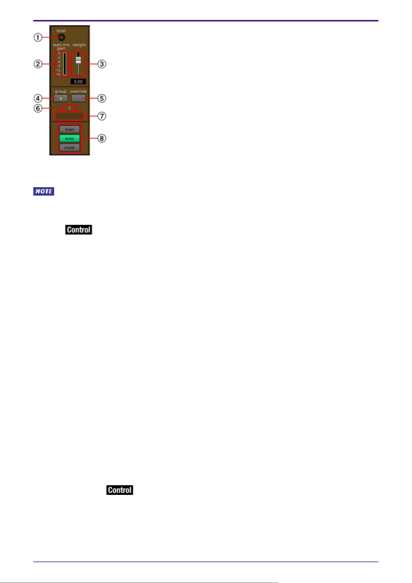
① [level] indicator
This lights green when the audio reaches the appropriate level for automixing.
・If the [level] indicator goes dark, raise the input gain.
・If the [level] indicator turns red, lower the input gain.
② Meter
The meter provides three display modes: gain (green: automix gain) /input (yellow: input level) /output
(blue: output level). The display mode switches each time you press the [meters] button in the main
control field.
③ [weight] slider
Adjusts the relative sensitivity between input channels. Set the meter display to “gain,” and adjust the
weight setting so that the meters are at approximately the same level when there is no input. For
example if noise is heard near a certain mic (e.g., air conditioner wind noise), lowering the weight value
of that channel will reduce the noise.
The automixer calculates the proportion of a specific channel’s input level relative to the mix of all
inputs in the group. The following examples describe how weight control works.
● If the weight setting value is raised on one channel
• The automix gain value of that channel increases, and the value of other channels decreases.
• Channels with a high weight setting will more easily obtain automix gain in comparison to other
channels.
● If the weight setting value is lowered on one channel
• The automix gain value of that channel decreases, and the value of other channels increases.
• If people speak simultaneously into multiple mics, it will be more difficult to differentiate them
from the other mics.
④ [group] button
Selects the group to which each channel belongs. Click the button to switch the group.
⑤ [override] button
When the main control field’s [OVERRIDE] button is on, the setting of this button determines whether
the corresponding channel switches to “man” mode or “mute” mode.
• If you turn on the [OVERRIDE] button of the main control field when the [override] button of
the channel control field is on, the channel mode changes to “man.”
2. Audio Components
ProVisionaire Design Component Guide | 103
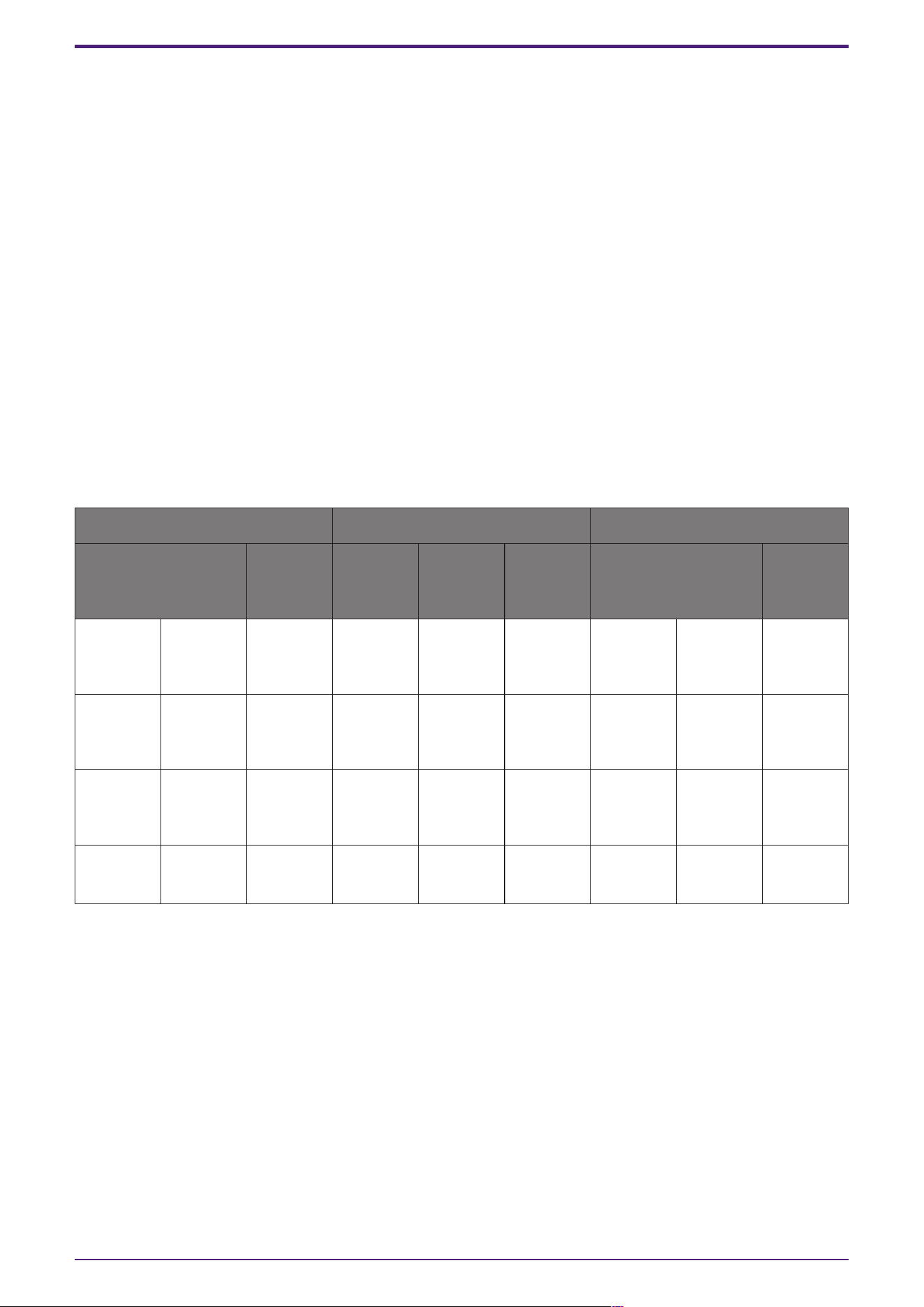
• If you turn on the [OVERRIDE] button of the main control field when the [override] button of
the channel control field is off, the channel mode changes to “mute.”
• When the [OVERRIDE] button of the main control field is turned off, that channel returns to its
previous mode.
⑥ Input channel number
Indicates the input channel number.
⑦ Port name
Shows or edits the port name. This is linked with the “Label” of the component’s ports.
⑧ [man]/[auto]/[mute] buttons
These buttons toggle the channel between man/auto/mute.
man : The audio is passed through without modifying the gain. Select this mode if singing into the mic.
auto : The automixer is turned on. Select this mode for conversation.
mute : The channel is muted.
2.36.2. Control
Parameter types of the input/output values for each Port
Input Value Control Parameter Output Value
Type Range Input
Port
Name
Paramete
r Range
Output
Port
Name
Type Range
Value Num 0,1 ●
override
Ch1
OFF:0,
ON:1
●
override
Ch1
Value Num
OFF:0,
ON:1
- - - - −∞–10.00 ● auto
mix gain
a
Value dB −∞–10.00
Value Num 0,1 ● group
override
a
OFF:0,
ON:1
● group
override
a
Value Num
OFF:0,
ON:1
- - - -
OFF:0,
ON:1
● group
mute a
Value Num
OFF:0,
ON:1
2. Audio Components
104 | ProVisionaire Design Component Guide
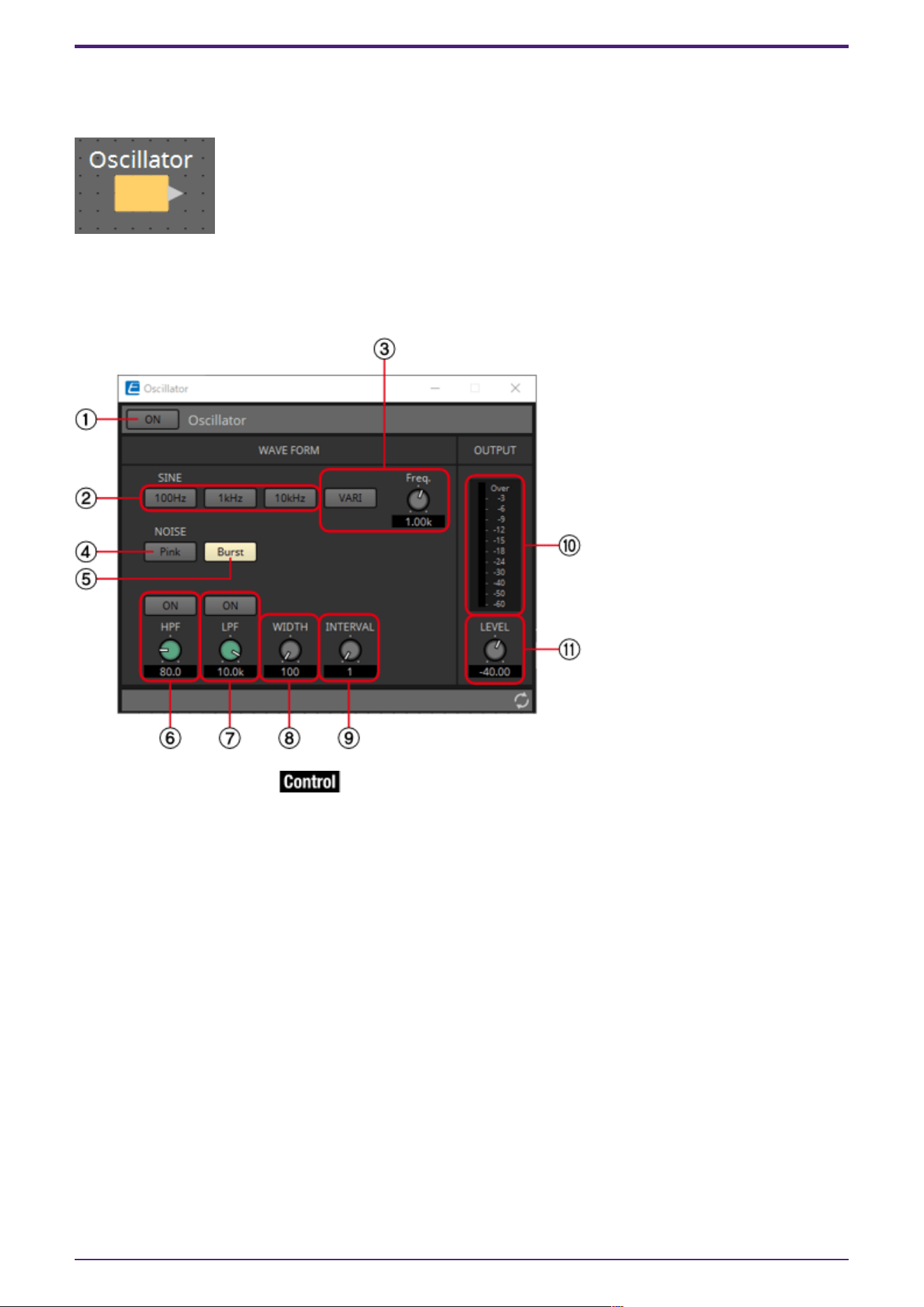
2.37. Oscillator
The DME provides a mono channel oscillator.
2.37.1. “Oscillator” component editor
Here you can specify the generated waveform and its level.
① Oscillator [ON] button
Specifies whether the specified signal is output.
② [100Hz]/[1kHz]/[10kHz] button
These buttons output a sine wave of the corresponding frequency.
③ [VARI] button/[Freq.] knob
If this button is on, a sine wave of the frequency specified by the knob is output.
④ [Pink] button
Outputs pink noise.
⑤ [Burst] button
Pink noise is output intermittently.
⑥ [HPF] knob
Indicates the cutoff frequency of the HPF that processes the pink noise. Use the knob to adjust the
value. Use the button above the knob to switch the HPF on or off.
This knob is displayed if PINK NOISE or BURST NOISE is selected.
2. Audio Components
ProVisionaire Design Component Guide | 105
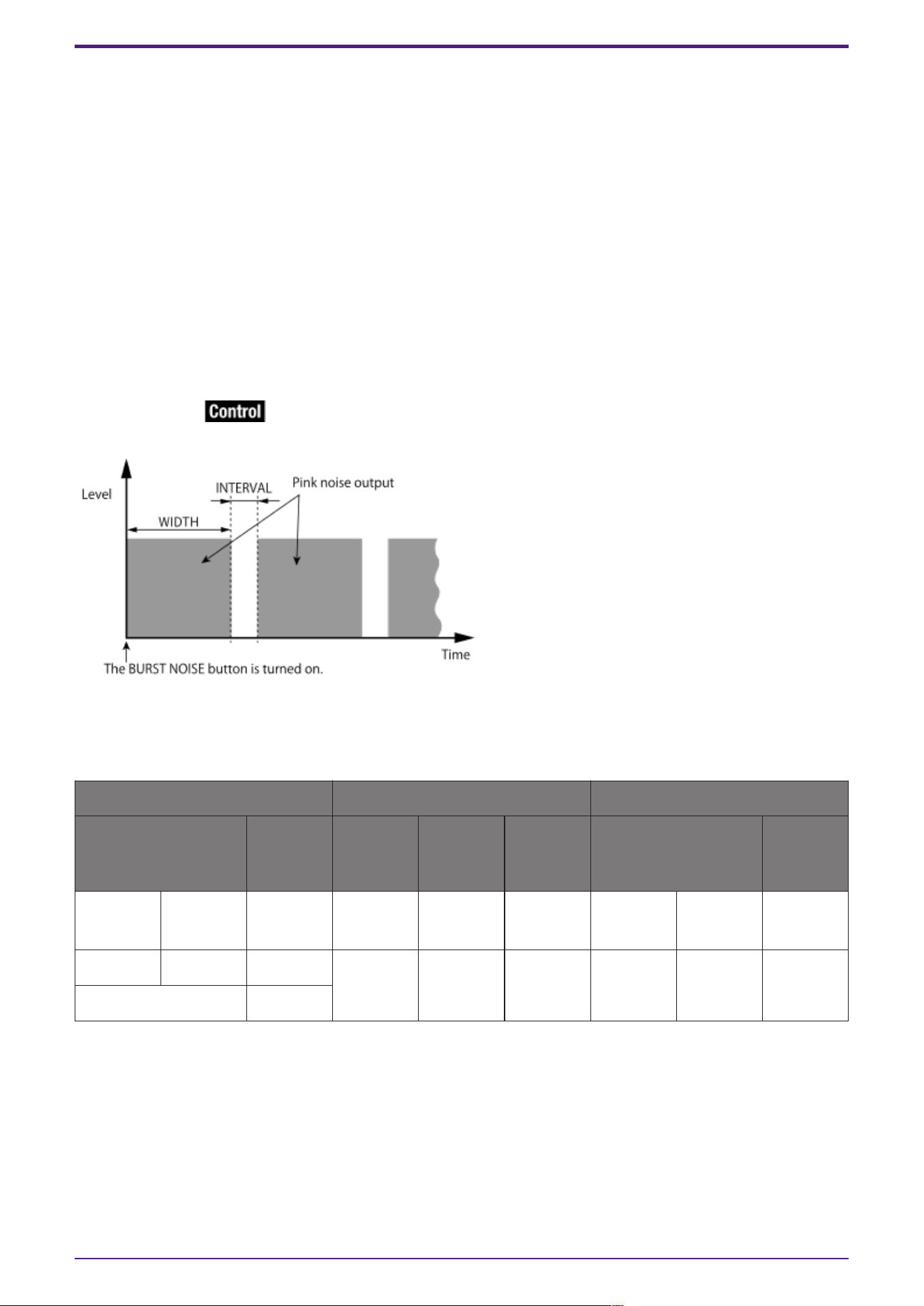
⑦ [LPF] knob
Indicates the cutoff frequency of the LPF that processes the pink noise. Use the knob to adjust the
value. Use the button above the knob to switch the LPF on or off.
This knob is displayed if PINK NOISE or BURST NOISE is selected.
⑧ [WIDTH] knob
Adjusts the length of noise being output intermittently.
This knob is displayed if BURST NOISE is selected.
⑨ [INTERVAL] knob
Adjusts the length of silence between noise bursts.
This knob is displayed if BURST NOISE is selected.
⑩ Meter
Shows the level of the signal that is being output.
⑪ [LEVEL] knob
Specifies the output level.
2.37.2. Control
Parameter types of the input/output values for each Port
Input Value Control Parameter Output Value
Type Range Input
Port
Name
Paramete
r Range
Output
Port
Name
Type Range
Value Num 0,1 ● On
OFF:0,
ON:1
● On Value Num
OFF:0,
ON:1
Value dB −∞–10.00 ● Level −∞–10.00 ● Level Value dB −∞–10.00
Normalized 0.00–1.00
2. Audio Components
106 | ProVisionaire Design Component Guide
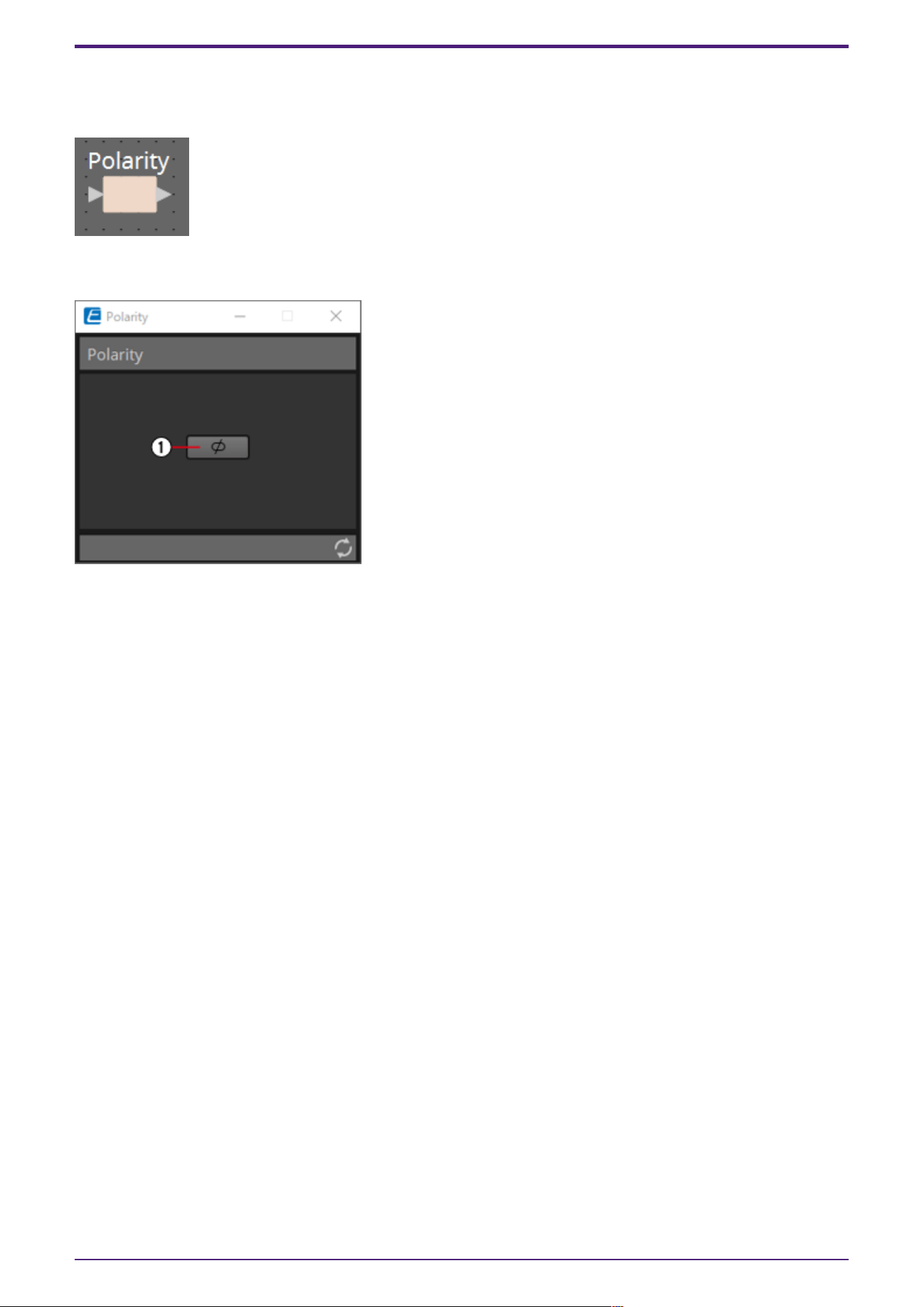
2.38. Polarity
This inverts the polarity of the input signal, and outputs the result.
2.38.1. “Polarity” component editor
① [⌀] button
If this is on, the polarity of the input signal is inverted, and the result is output.
2.38.2. Control
There are no parameters that can be controlled through the Control layer.
2. Audio Components
ProVisionaire Design Component Guide | 107
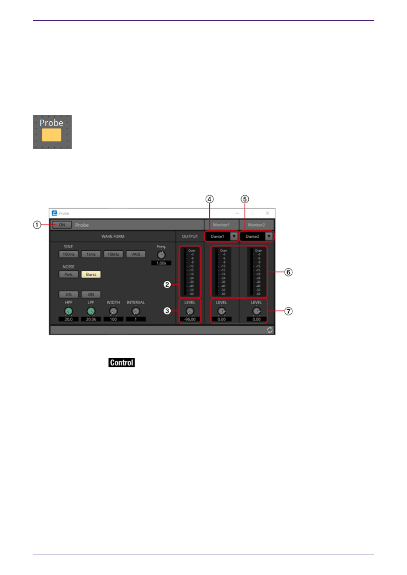
2.39. Probe
Probes have 2 functions. The first is to monitor any output point. Using two probes, each signal can be
independently and simultaneously monitored, and the relationship between the two signals can also be
checked. When output to Dante, you can listen to audio on a computer using the Dante Virtual
Soundcard. In addition, 2 outputs can be input to Smmart to see the correlation. The other function of
a probe is to temporarily interrupt the oscillator signal to a specific input point. For details about the
oscillator, refer to “Oscillator” component editor.
Each DME sets whether the probe is ON or OFF.
Only one component can be placed.
2.39.1. ”Probe” component editor
① Probe [ON] button
Turns the probe monitor function ON or OFF. The cursor changes to the probe shape.
② OUTPUT meter
Displays the output signal level of Oscillator.
③ OUTPUT[LEVEL] knob
Specifies the output level of Oscillator.
④ Monitor 1
You can select from Dante Out 1–256 and USB Out 1–8 for the Monitor 1 output.
⑤ Monitor 2
You can select from Dante Out 1–256 and USB Out 1–8 for the Monitor 2 output.
⑥ [Monitor 1]/[Monitor 2] meter
This displays the signal level being output.
⑦ [LEVEL] knob
Specifies the output level.
2. Audio Components
108 | ProVisionaire Design Component Guide
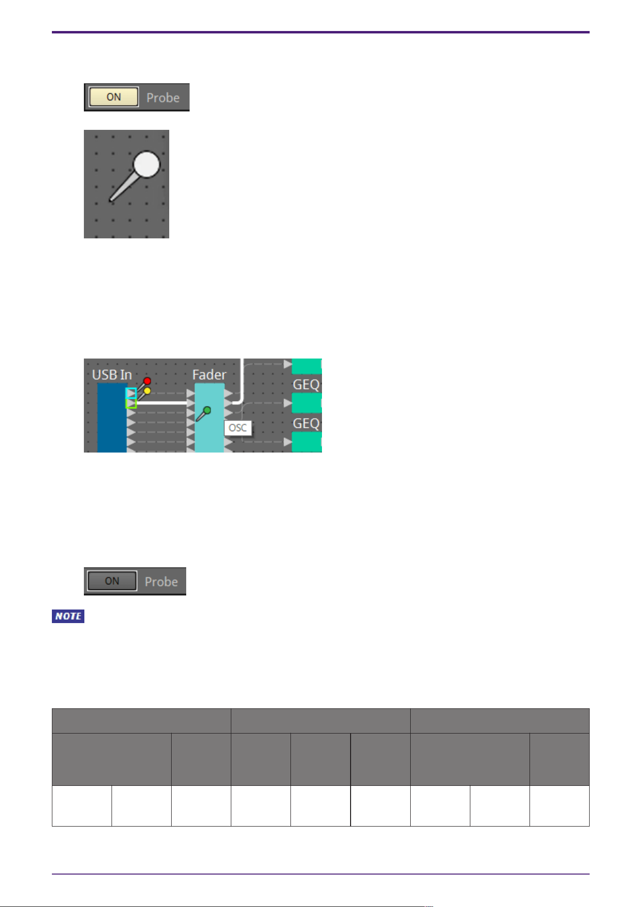
Procedure
1.
With the device in an online state, turn the probe monitor function ON.
The cursor changes to the probe shape.
2. By clicking on any of the output ports for the component, the probe is set as the monitoring
point "Monitor1."
The monitoring point can be moved by clicking on a different output port.
The monitoring point is removed by clicking again on the selected port.
Holding <Shift> key on the computer keyboard while clicking on an output port sets the probe as
monitoring point 2.
Moving and removing the monitoring point is the same as for Monitor1.
The red probe is the point monitoring for Monitor1, the yellow probe is monitoring for Monitor2,
and the green probe is the location interrupting the oscillator.
3. You can select from Dante Out 1–256 and USB Out 1–8 for the Monitor 1 and Monitor 2 outputs.
Even if audio is originally wired to the above port, it is replaced with the output of the Probe
component.
4. Turn the probe monitor function OFF to cancel the probe. The mouse cursor display returns to
normal.
As long as Probe is not set to OFF, the Probe will not be canceled, even if the Probe component
window is closed.
2.39.2. Control
Parameter types of the input/output values for each Port
Input Value Control Parameter Output Value
Type Range Input
Port
Name
Paramete
r Range
Output
Port
Name
Type Range
Value Num 0,1 ● On
OFF:0,
ON:1
● On Value Num
OFF:0,
ON:1
2. Audio Components
ProVisionaire Design Component Guide | 109
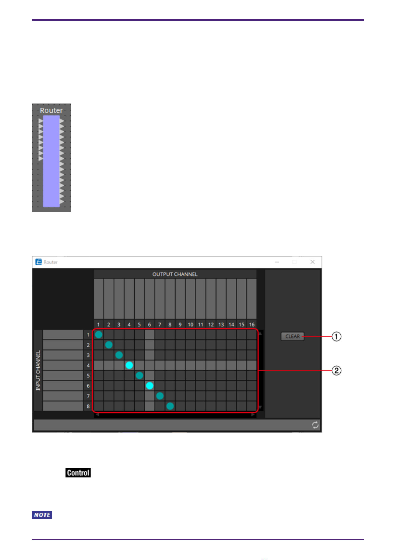
2.40. Router
This component distributes inputs to output ports. Although one input can be output to multiple
channels, multiple inputs cannot be output to a single channel.
Select the number of channels (maximum 256In/256Out) when you place this component in the design
sheet. The number of Dante Input/Output channels is determined by the number of activated device
licenses. In the explanation here, the illustration shows the example of 8 input channels and 16 output
channels.
2.40.1. “Router” component editor
Here you can specify how the signals are distributed.
① [CLEAR] button
Turns all outputs off.
② Router
This is a router that distributes the signals. Click a square in the grid to switch the output on/off.
When you double-click a port name display area located above or to the left of the router, a window
opens, allowing you to edit the name of the port.
The grid squares can also be registered in a Parameter Set or Remote Control List by holding
down <Ctrl> key on the computer keyboard and dragging and dropping.
2. Audio Components
110 | ProVisionaire Design Component Guide

2.40.2. Control
Parameter types of the input/output values for each Port
Input Value Control Parameter Output Value
Type Range Input
Port
Name
Paramete
r Range
Output
Port
Name
Type Range
Value Num 0,1 ● Out1
In1
OFF:0,
ON:1
● Out1
In1
Value Num
OFF:0,
ON:1
Value Num 1,2… ● Out1
Sel
1:1, 2:2
…
● Out1
Sel
Value Num 1:1, 2:2
…
2. Audio Components
ProVisionaire Design Component Guide | 111
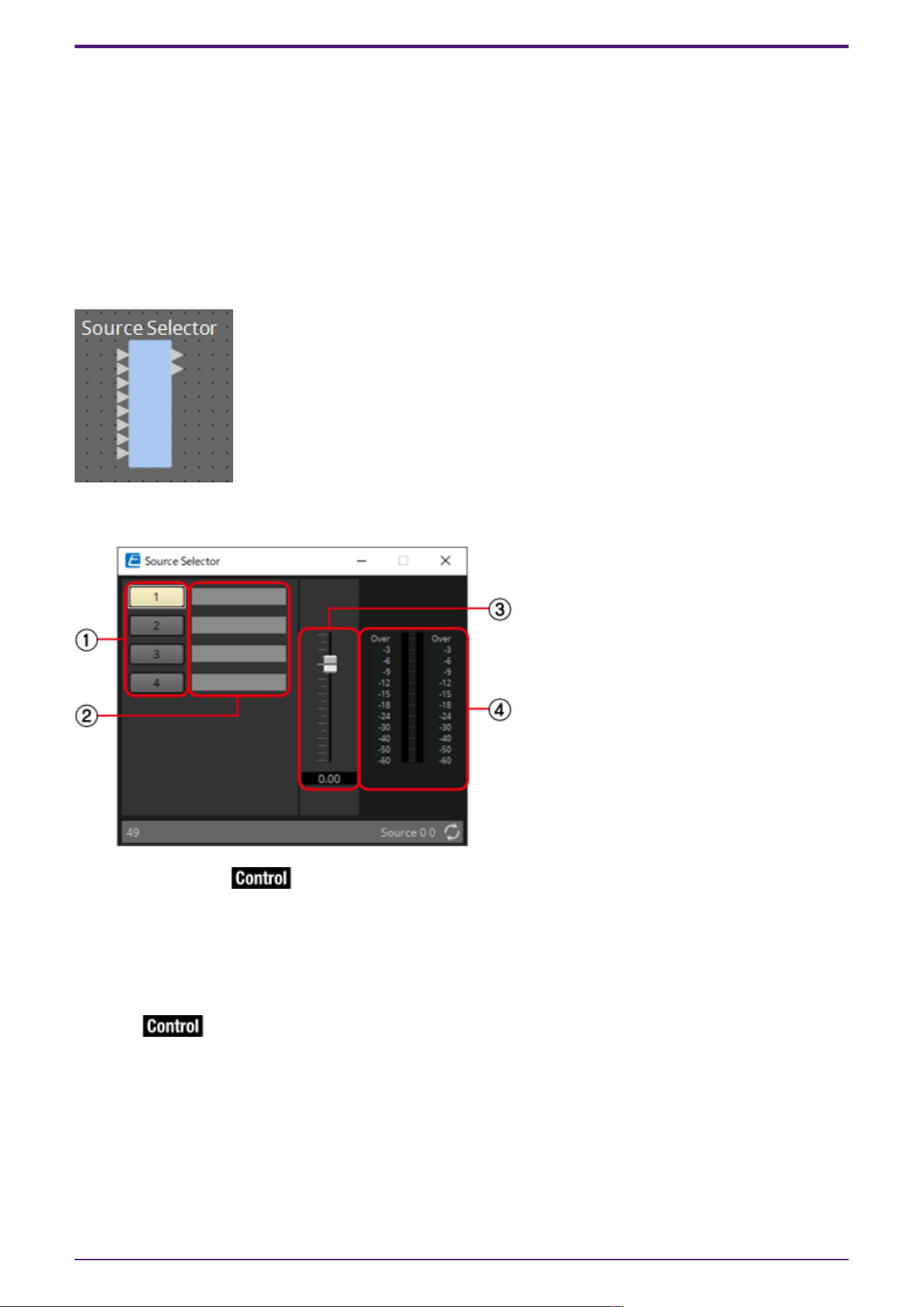
2.41. Source Selector
This selects one source from multiple input sources.
Source indicates the number of input sources, and Channel indicates the number of channels of those
sources.
For example, a “4 Source 2 Channel” component selects one 2-channel source from four 2-channel
sources.
When placing this component in the design sheet, select the number of input sources (4/8/16) and the
number of channels in those sources (1/2/6 in the case of 4/8 input sources, or 1/2 in the case of 16
input sources). The explanatory illustration here shows the example of four input sources where each
source has two channels.
2.41.1. “Source Selector” component editor
① Selector buttons
Select the source that will be output.
② Port name
Shows or edits the port name.
This is linked with the “Label” of the component’s ports.
③ Fader
The output level of the selected source can be adjusted.
④ Output level display
This is a level display for each channel of the selected source.
2. Audio Components
112 | ProVisionaire Design Component Guide

2.41.2. Control
Parameter types of the input/output values for each Port
Input Value Control Parameter Output Value
Type Range Input
Port
Name
Paramete
r Range
Output
Port
Name
Type Range
Value Num 1, 2… ● Source 1:1, 2:2
…
● Source Value Num 1:1, 2:2
…
Value dB −∞–10.00 ● Source
Level
−∞–10.00 ● Source
Level
Value dB −∞–10.00
Normalized 0.00–1.00
2. Audio Components
ProVisionaire Design Component Guide | 113
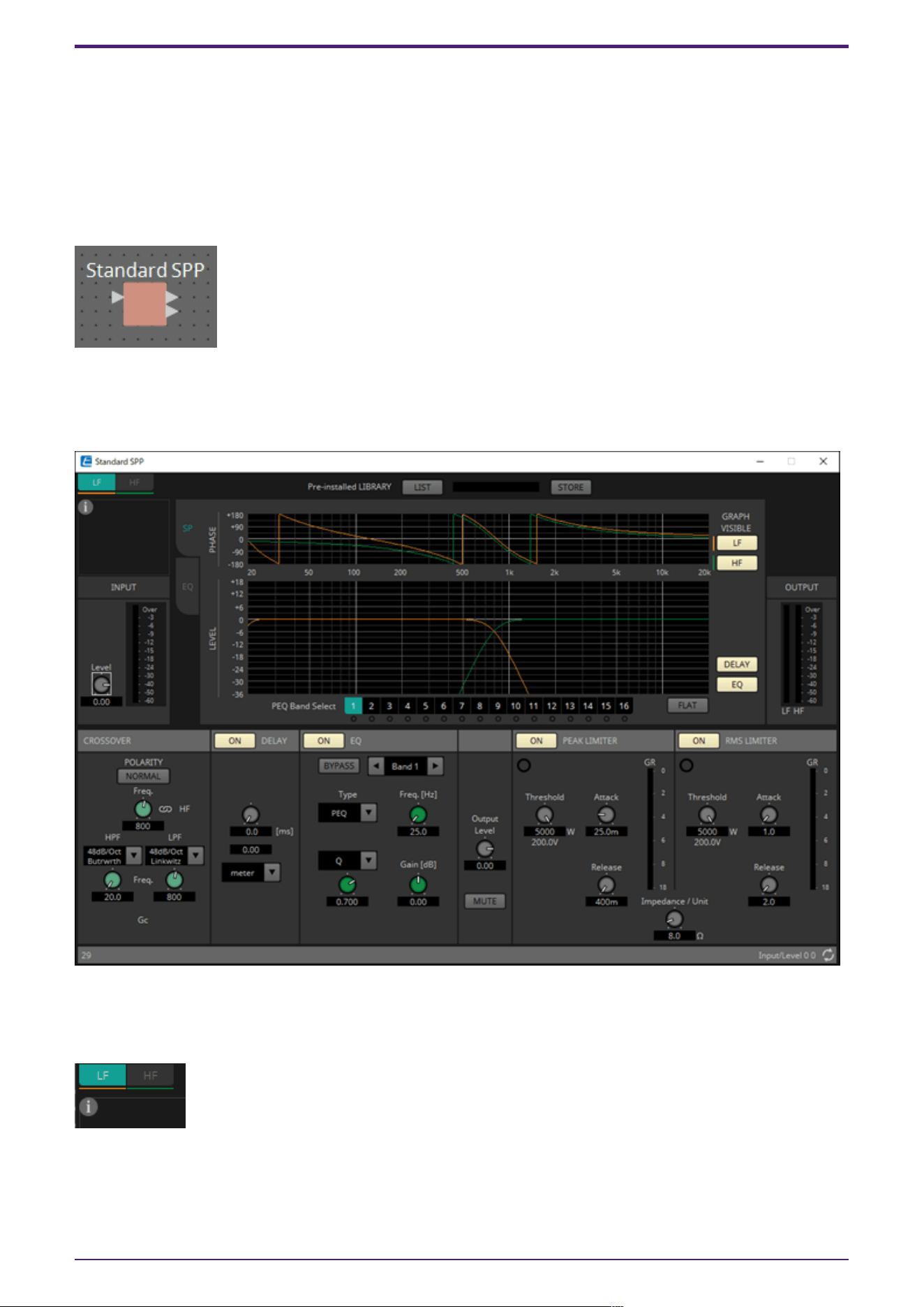
2.42. Speaker Processor: Standard SPP
The speaker processor is a crossover processor for speaker adjustment; it includes an APF (All Pass
Filter), Horn EQ, and limiter.
When placing this component in the design sheet, select the number of output channels to the
speakers that are connected. Select “1” if the connected speakers are used in single amp mode (full
range), select “2” for bi-amp mode, select “3” for tri-amp mode, and select “4” for quad-amp mode.
The illustrations used in the following explanation are for the case of bi-amp mode.
2.42.1. ”Standard SPP” component editor
Here you can view the Speaker Processor parameter response.
Channel switching tabs
Switch between the channels whose settings you want to edit.
Library information (Only for C-Series SPP(FIR) component)
Shows library information when a speaker library item is recalled.
2. Audio Components
114 | ProVisionaire Design Component Guide
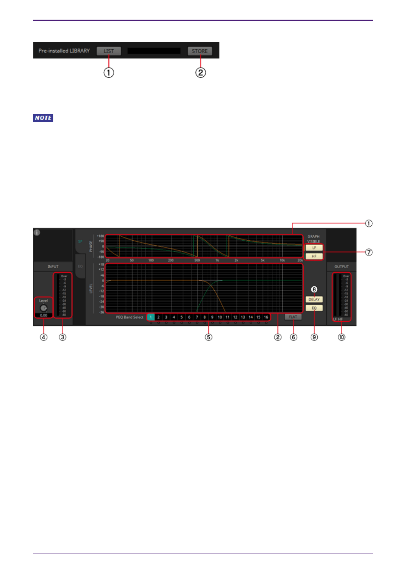
Pre-installed LIBRARY
① [LIST] button
Selects and shows library items.
In the libraries that are pre-installed in ProVisionaire Design, the LIMITER’s Threshold value is
set to the value that is appropriate when using a power amp with 26 dB voltage gain. As necessary,
make appropriate adjustments to the DME’s LIMITER settings and output level, and to the power amp’s
voltage gain and attenuator. For example if using a power amp whose voltage gain is 30 dB, you should
either lower the power amp’s attenuator value by 4 dB or lower the DME’s LIMITER Threshold value by
4 dB.
② [STORE] button
Saves the current state as a library item (file extension [.spld]).
[SP] tab
① [PHASE] graph
Displays a crossover phase response curve. This display takes into account the response of the PEQ and
the Delay. Output channels are color-coded.
② [LEVEL] graph
Displays a crossover amplitude response curve. This display takes into account the response of the PEQ
and the Output Level. Output channels are color-coded.
③ [INPUT] meter
Shows the input signal level.
④ INPUT [Level] knob
Specifies the input level. You can double-click the numeric display area and directly enter a numeric
value.
⑤ [Band Select] buttons
If a button is selected, the current value is shown in "EQ," below. For bands whose [BYPASS] button is
on, the indicator below that [Band Select] button is lit.
⑥ [FLAT] button
Sets the "EQ" [GAIN] to 0 dB.
2. Audio Components
ProVisionaire Design Component Guide | 115
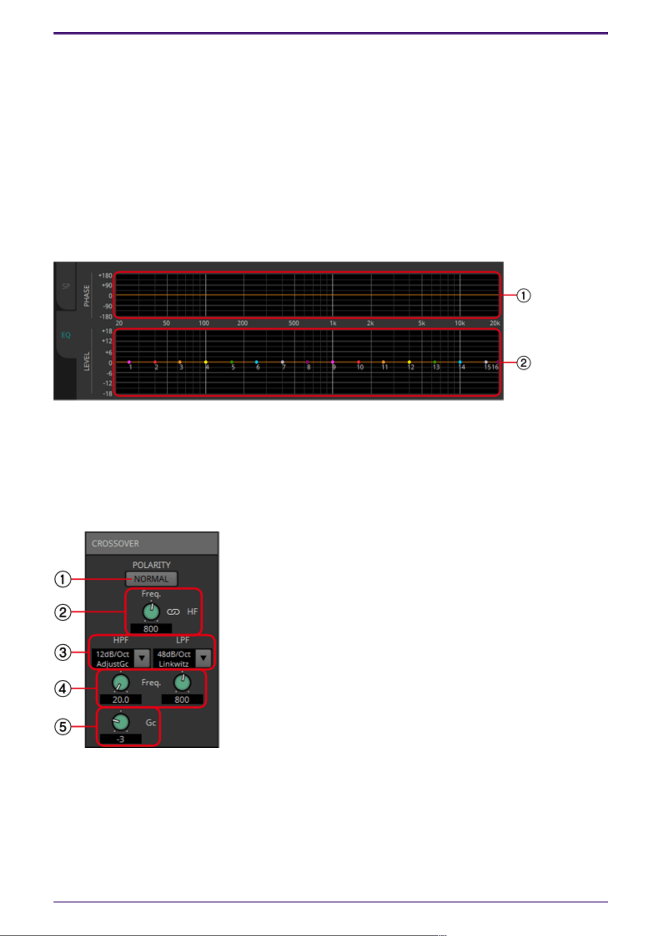
⑦ GRAPH VISIBLE button
These buttons switch the graph of the corresponding output channel between visible and hidden. These
are shown if there are multiple output channels.
⑧ [DELAY] button
Shows or hides the DELAY response in the crossover curve that is displayed.
⑨ [EQ] button
Shows or hides the PEQ response in the crossover curve that is displayed.
⑩ [OUTPUT] meter
Displays the output signal level of each output channel.
[EQ] tab
① [PHASE] graph
Displays the EQ phase response curve.
② [LEVEL] graph
Displays the EQ amplitude response curve.
CROSSOVER
① POLARITY[NORMAL]/[INVERTED] button
Specify whether the polarity of each output channel will be inverted.
② [Freq.] knob
Specifies the crossover frequency of each output channel.
2. Audio Components
116 | ProVisionaire Design Component Guide
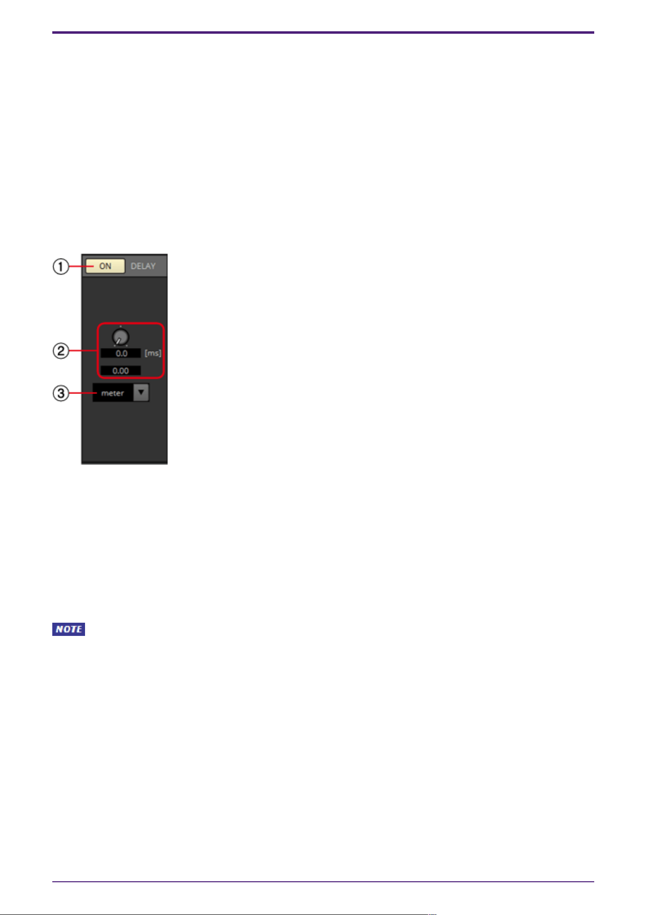
③ [HPF]/[LPF] list box
Select the attenuation per octave and filter type for each output channel. For details on the
attenuation slope and filter types, refer to “Filter”.
④ HPF/LPF [Freq.] knobs
Specify the cutoff frequency of the HPF and LPF
⑤ [Gc] knob
When [AdjustGc] (Adjustable Gc) is selected in the [HPF]/[LPF] list box, this knob specifies the gain
at the cutoff frequency.
DELAY
Here you can make delay settings for each output channel.
① DELAY [ON] button
Switches the delay function between enabled and disabled.
② Delay Time knob
Specifies the delay time.
③ Type list box
The delay time specified by the Delay Time knob is converted into the units you select, and shown
above.
SSample is shown based on the frequency specified in the ProVisionaire Design “Word Clock”
dialog box.
2. Audio Components
ProVisionaire Design Component Guide | 117
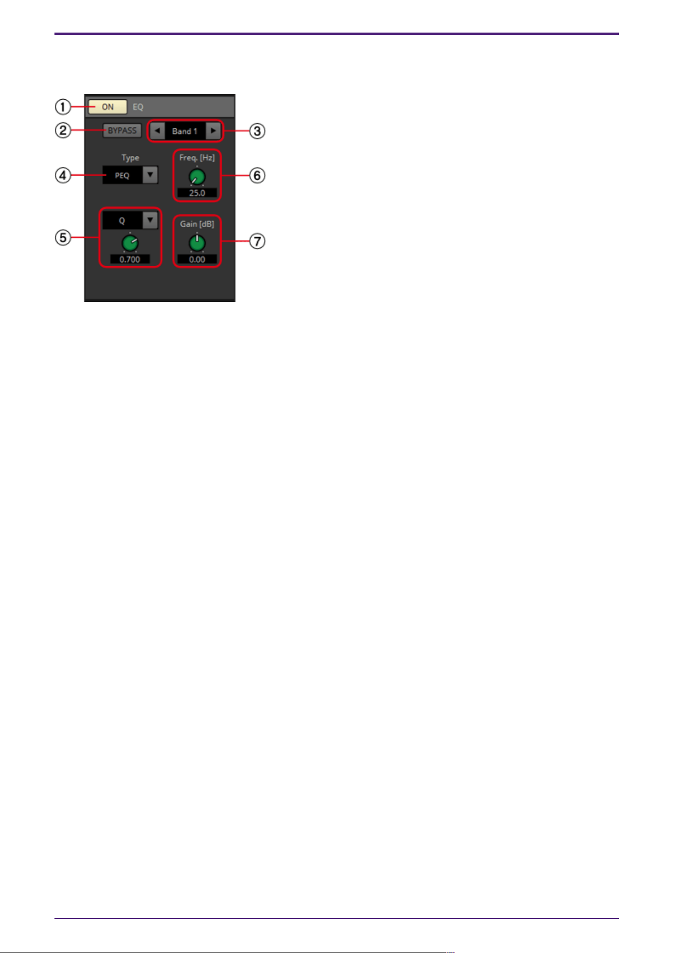
EQ
Here you can make PEQ settings for each output channel.
① EQ [ON] button
Switches the EQ function between enabled and disabled.
② [BYPASS] button
Specifies whether each band is bypassed. If you click a button to make it light, that band is bypassed.
③ Band slide banner
Selects the band for which to make EQ settings.
④ [Type] list box
Selects the type of filter that is used for each band. The number of knobs below increases or
decreases according to the type that you select. The following types of filter are provided.
•
PEQ (Parametric Equalizer)
The volume in the region of the specified frequency will be boosted or cut for the width
specified by the Q setting.
•
L.SHELF (Low Shelf)
The volume of the entire low-frequency region below the specified frequency will be boosted or
cut. Use this for purposes such as bass boost. [6dB/Oct] and [12dB/Oct] specify the amount of
attenuation per octave.
•
H.SHELF (High Shelf)
The volume of the entire high-frequency region above the specified frequency will be boosted or
cut. Use this for purposes such as high boost. [6dB/Oct] and [12dB/ Oct] specify the amount of
attenuation per octave.
•
HPF(High Pass Filter)
The region below the specified frequency will be cut.
•
LPF(Low Pass Filter)
The region above the specified frequency will be cut.
•
APF 1st/2nd (All Pass Filter)
Passes the signals of the entire frequency range, affecting only the phase. It is used to correct
the phase of the crossover region.
APF 1st rotates the phase 0˚–180˚, and APF 2nd rotates the phase 0˚–360˚. APF 2nd allows you
to set the Q.
2. Audio Components
118 | ProVisionaire Design Component Guide
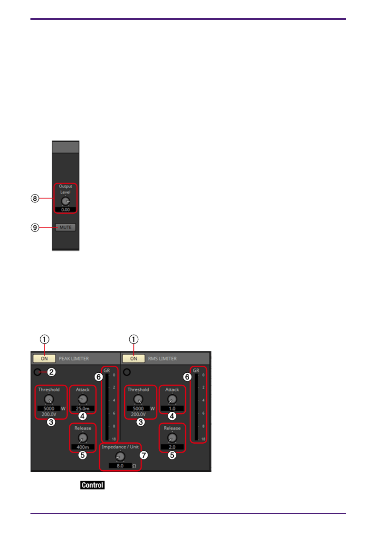
•
Horn EQ
A horn speaker is characterized by a high frequency level roll-off. Horn EQ compensates for this
tendency.
⑤ Q-B/W [OCT] list box/knob
Use the list box to select the type of width for each frequency band, and use the knob to specify the
width. For [B/W], the setting is in Octave units.
⑥ Freq.[Hz] knob
Adjusts the center frequency of each band.
⑦ Gain[dB] knob
Specifies the gain in each band’s frequency region.
⑧ [Output Level] knob
Specifies the output level of each output channel. This is reflected in the "LEVEL" graph of the [SP]
tab.
⑨ [MUTE] button
If this is on, the output is muted, and its crossover graph is shown as a dotted line.
PEAK LIMITER/RMS LIMITER
① [ON] button
Switches the limiter function between enabled and disabled.
2. Audio Components
ProVisionaire Design Component Guide | 119
② Gain Reduction indicator
This will light when the threshold value is exceeded.
③ [Threshold] knob
Specifies the threshold level at which the Limiter is applied.
④ [Attack] knob
Specifies the speed at which the limiter will take effect.
⑤ [Release] knob
Specifies the speed at which the limiter will release.
⑥ [GR] meter
Indicates the amount of gain reduction.
⑦ [Impedance/Unit] knob
Specifies the nominal impedance of the speaker.
Even when connecting multiple speakers in parallel, specify this as the impedance of one unit.
2.42.2. Control
Parameter types of the input/output values for each Port
Input Value Control Parameter Output Value
Type Range Input
Port
Name
Paramete
r Range
Output
Port
Name
Type Range
Value Num 0,1 ●
PeakLimit
er On
OFF:0,
ON:1
●
PeakLimit
er On
Value Num
OFF:0,
ON:1
Value dB −∞–10.00 ●
PeakLimit
er
Threshold
−∞–10.00 ●
PeakLimit
er
Threshold
Value dB −∞–10.00
Normalized 0.00–1.00
- - - -
OFF:0,
ON:1
●
PeakLimit
er
Exceeded
Value Num
OFF:0,
ON:1
Value Num 0,1 ●
RMSLimit
er On
OFF:0,
ON:1
●
RMSLimit
er On
Value Num
OFF:0,
ON:1
Value dB −∞–10.00 ●
RMSLimit
er
Threshold
−∞–10.00 ●
RMSLimit
er
Threshold
Value dB −∞–10.00
Normalized 0.00–1.00
- - - -
OFF:0,
ON:1
●
RMSLimit
er
Exceeded
Value Num
OFF:0,
ON:1
2. Audio Components
120 | ProVisionaire Design Component Guide
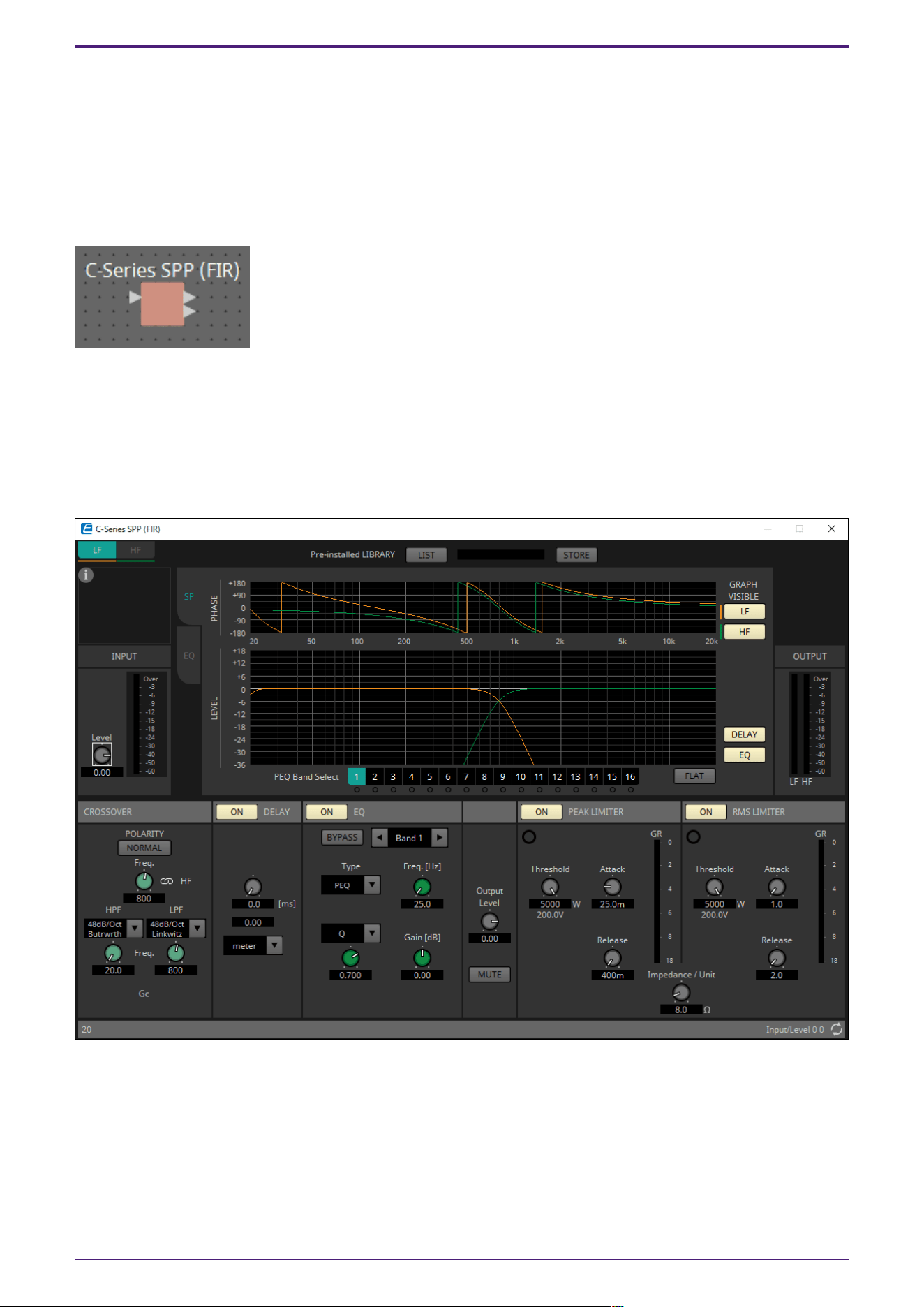
2.43. Speaker Processor: C-Series SPP (FIR)
The speaker processor is a crossover processor for speaker adjustment; it includes an APF (All Pass
Filter), Horn EQ, and limiter.
When placing this component in the design sheet, select the number of output channels to the
speakers that are connected. Select “1” if the connected speakers are used in single amp mode (full
range) and select “2” for bi-amp mode.
The illustrations used in the following explanation are for the case of bi-amp mode.
2.43.1. ”C-Series SPP (FIR)” component editor
This is a speaker processor exclusively for libraries containing FIRs.
As of writing (January 2023), the CZR speaker presets can be loaded (but not edited).
The extension for a C-Series SPP (FIR) Library is .spldf. The extensions for a Standard SPP Library and
a C-Series SPP (FIR) Library are different, and they cannot load a file for the other.
The setting method is the same as Standard SPP, but the library information that can be displayed is
only for the C-Series SPP (FIR).
2. Audio Components
ProVisionaire Design Component Guide | 121
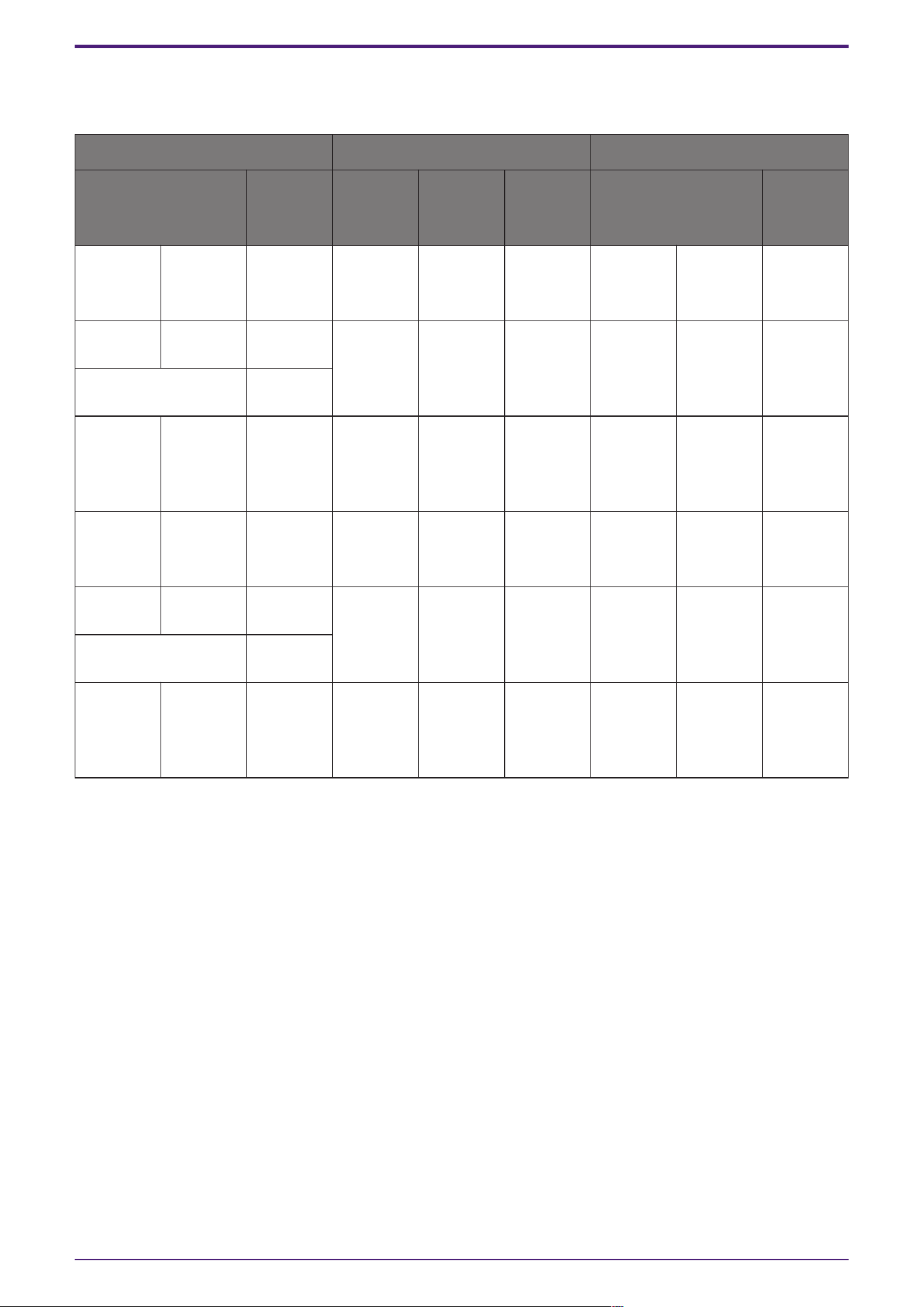
2.43.2. Control
Parameter types of the input/output values for each Port
Input Value Control Parameter Output Value
Type Range Input
Port
Name
Paramete
r Range
Output
Port
Name
Type Range
Value Num 0,1 ●
PeakLimit
er On
OFF:0,
ON:1
●
PeakLimit
er On
Value Num
OFF:0,
ON:1
Value dB −∞–10.00 ●
PeakLimit
er
Threshold
−∞–10.00 ●
PeakLimit
er
Threshold
Value dB −∞–10.00
Normalized 0.00–1.00
- - - -
OFF:0,
ON:1
●
PeakLimit
er
Exceeded
Value Num
OFF:0,
ON:1
Value Num 0,1 ●
RMSLimit
er On
OFF:0,
ON:1
●
RMSLimit
er On
Value Num
OFF:0,
ON:1
Value dB −∞–10.00 ●
RMSLimit
er
Threshold
−∞–10.00 ●
RMSLimit
er
Threshold
Value dB −∞–10.00
Normalized 0.00–1.00
- - - -
OFF:0,
ON:1
●
RMSLimit
er
Exceeded
Value Num
OFF:0,
ON:1
For Text, Transmitter/Receiver and User Defined Block, refer to the ProVisionaire Design User Guide.
2. Audio Components
122 | ProVisionaire Design Component Guide
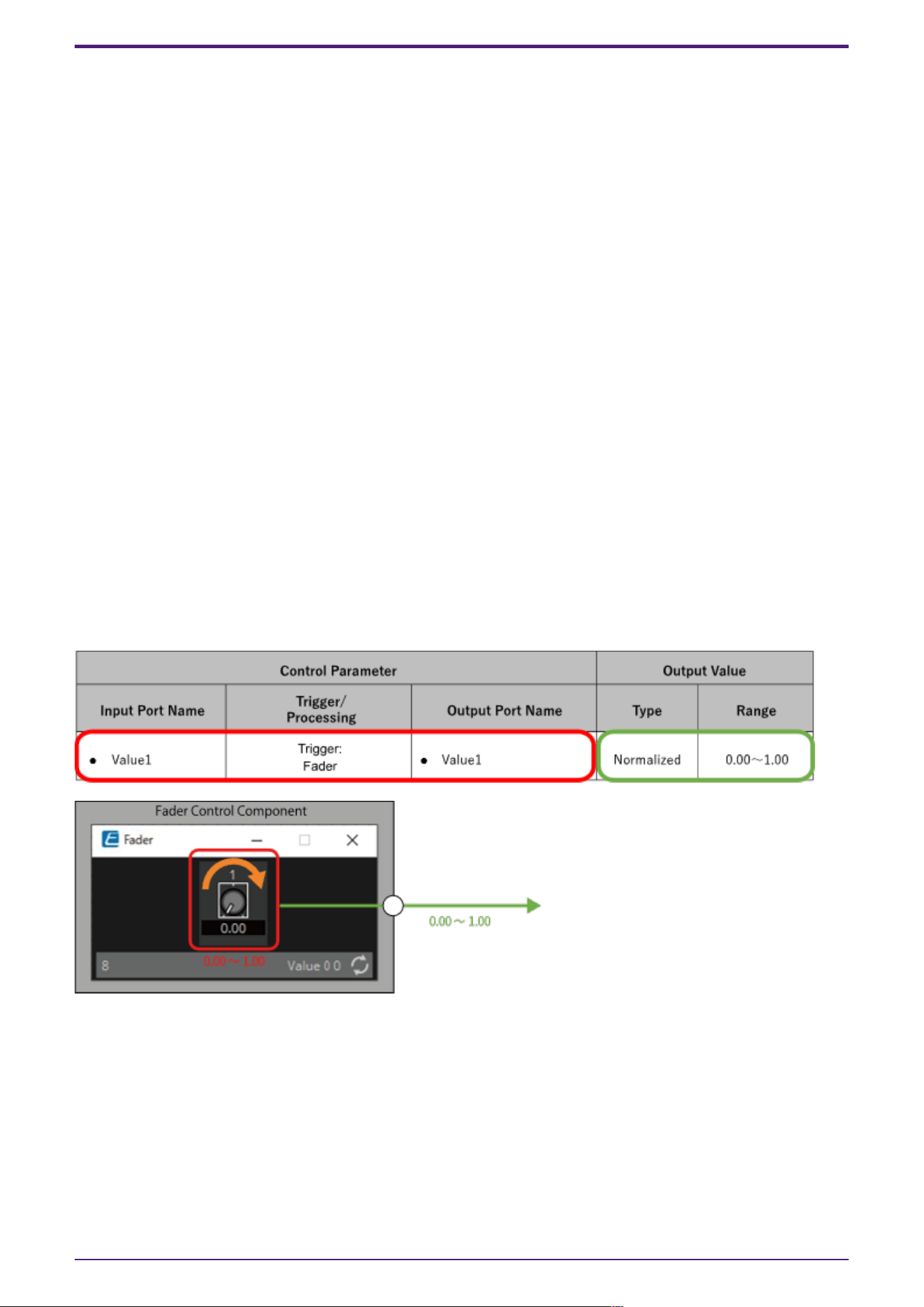
3. Control Components
3.1. Control Methods for Control Components
Control components can be divided into three broad types.
3.1.1. Trigger-type control components:
Trigger-type components are used primarily to output control signals through the operation of knobs,
buttons, etc. and to use those signals to control other components, or to execute desired processes by
sending control signals to processing-type components.
(It is also possible to move a controller by inputting a control signal.)
For trigger-type components, there are three types of controllers (Fader, Button, Radio Button) and
two types of data types (Value, Normalized Value) for the control signal output for each (control
signal input to the controlled component), for a total of six types of components.
The following example (Fader) explains how to use this list.
The fader control component can send continuous value control signals to the target component.
•
Control Parameter (Red outline):
The name of the port used to output the controller change notification (Output Port Name) and
the controller parameter type (Trigger/Processing). In addition, the name of the input port used
to externally control the controller (Input Port Name) is also listed.
•
Output Value (Green outline):
Data type and range of output values that are output when the controller is operated.
(Example) Fader (Normalized)
3.1.2. Processing-type control components:
Processing-type components output the result of specific processing in response to an input control
signal. The DME provides components for each of these process types.
The following example (NOT) explains how to use this list.
The NOT control component is a control component that inverts the input value (OFF:0, ON:1).
•
Control Parameter (Red outline):
The name of the port for input data for the Processing process (Input Port Name), the name of
the port for notification of the result of the Processing process (Output Port Name), and the
3. Control Components
ProVisionaire Design Component Guide | 123
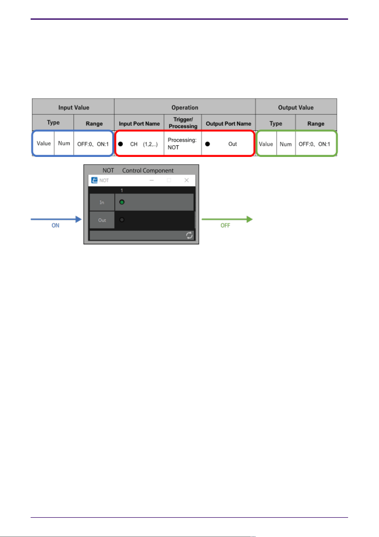
controller parameter type (Trigger/Processing).
•
Input Value (Blue outline):
Recommended data types and ranges for Processing process input values.
•
Output Value (Green outline):
Data type and range of the output value of the Processing process results.
(Example) NOT (Normalized Value)
3.1.3. Other:
Components of types other than the two described above (trigger type and processing type).
3. Control Components
124 | ProVisionaire Design Component Guide
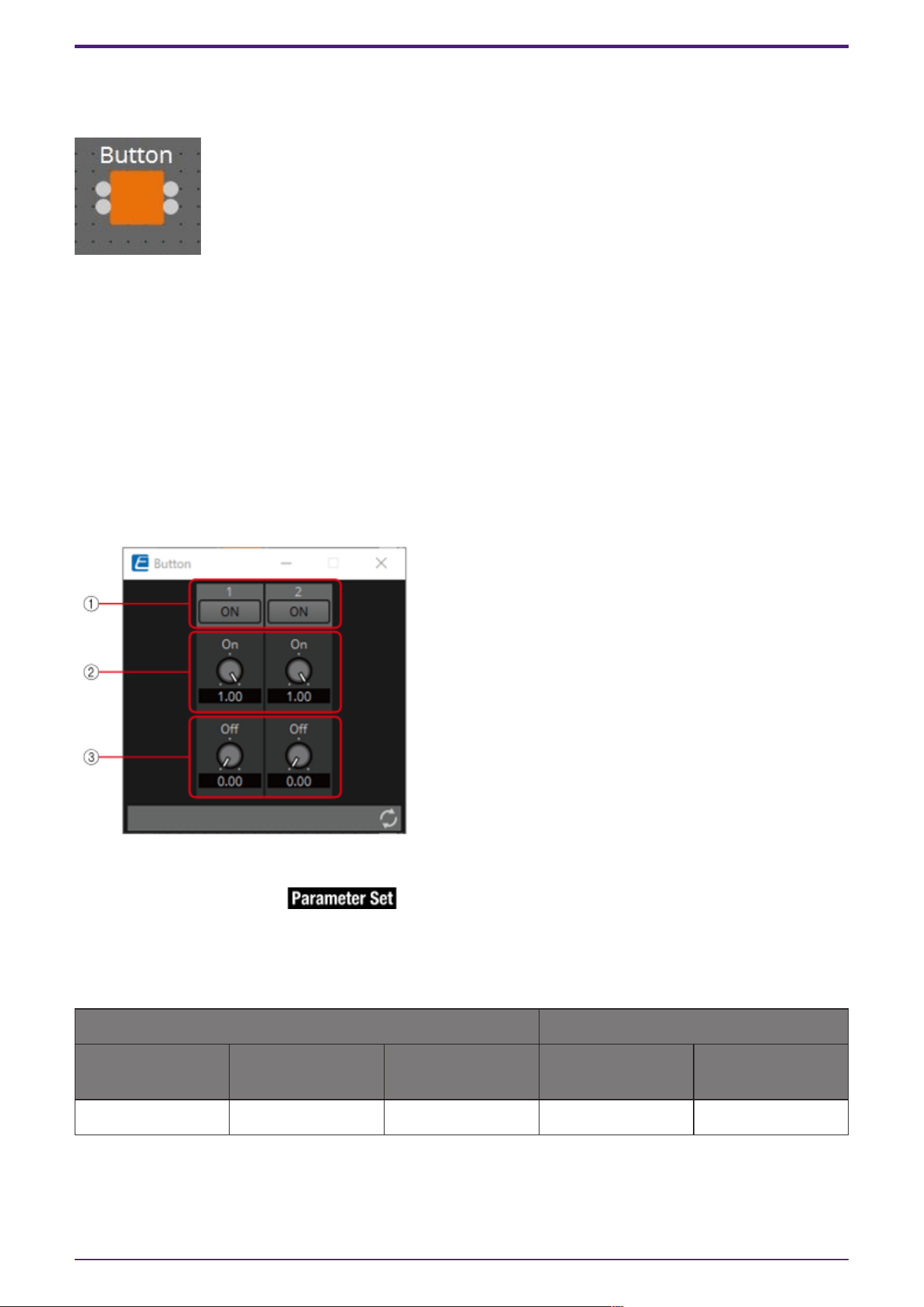
3.2. Input (Normalized Value): Button
Switching the Button’s on/off state causes output of the specified value (normalized value).
(For 2 inputs)
INPUT
On1: Input value to control the channel 1 button (OFF:0, ON:1)
On2: Input value to control the channel 2 button (OFF:0, ON:1)
OUTPUT
On1: Outputs the channel 1 setting value (0.00–1.00)
On2: Outputs the channel 2 setting value (0.00–1.00)
The button turns off when 0 is input from the input port, and turns on when 1 is input.
3.2.1. “Button” component editor
① When the button is switched on, the value set in ② is output, and when the button is switched off,
the value set in ③ is output.
② 0.00–1.00
③ 0.00–1.00
Parameter types of the input/output values for each Port
Operation Output Value
Input Port Name Trigger/Processin
g
Output Port Name Type Range
● On1 Trigger: Button ● On1 Normalized 0.00–1.00
* It is also possible to control the ON button by inputting OFF:0 and ON:1 in the Value (Num) data
type for the Input Port.
3. Control Components
ProVisionaire Design Component Guide | 125
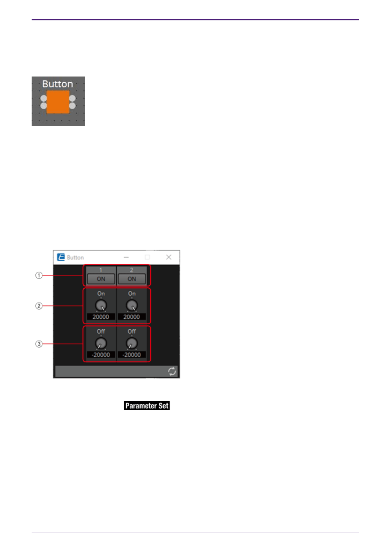
3.3. Input (Value): Button
Switching the button’s on/off state causes output of the specified value.
The type of output value (Num or dB) can be selected in the dialog that is displayed when the
component is placed.
(For 2 inputs)
INPUT
On1: Input value to control the channel 1 button (OFF:0, ON:1)
On2: Input value to control the channel 2 button (OFF:0, ON:1)
OUTPUT
On1: Outputs the channel 1 setting value (–20,000 to 20,000), (−∞ to 10.00)
On2: Outputs the channel 2 setting value (–20,000 to 20,000), (−∞ to 10.00)
The button turns off when 0 is input from the input port, and turns on when 1 is input.
3.3.1. ”Button” component editor (Num)
① When the button is switched on, the value set in ② is output, and when the button is switched off,
the value set in ③ is output.
② –20,000 to 20,000
③ –20,000 to 20,000
3. Control Components
126 | ProVisionaire Design Component Guide
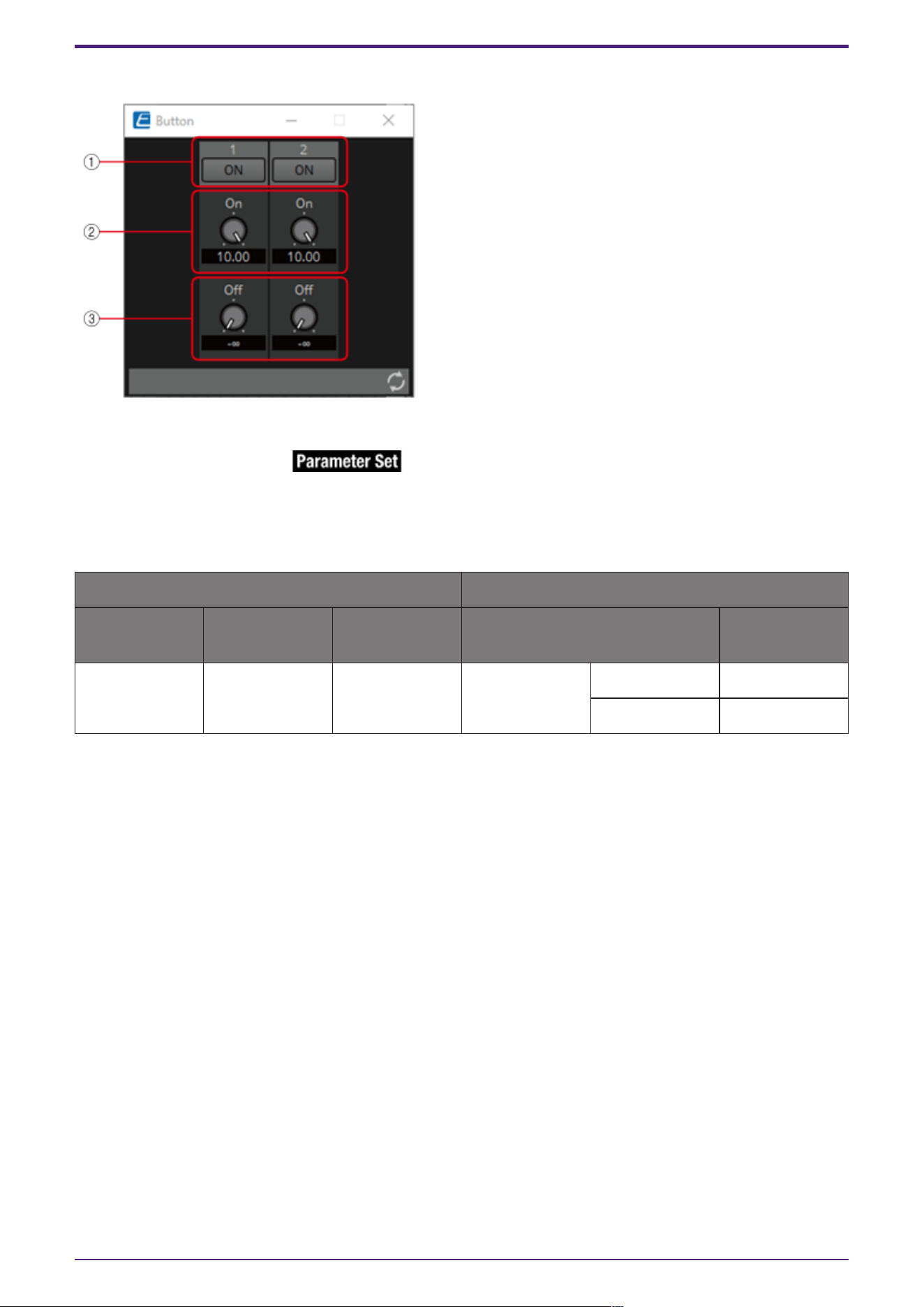
3.3.2. ”Button” component editor (dB)
① When the button is switched on, the value set in ② is output, and when the button is switched off,
the value set in ③ is output.
② −∞ to 10.00
③ −∞ to 10.00
Parameter types of the input/output values for each Port
Operation Output Value
Input Port
Name
Trigger/Proces
sing
Output Port
Name
Type Range
● On1 Trigger: Button ● On1 Value dB −∞–10.00
Num -20000–20000
* It is also possible to control the ON button by inputting OFF:0 and ON:1 in the Value (Num) data
type for the Input Port.
3. Control Components
ProVisionaire Design Component Guide | 127
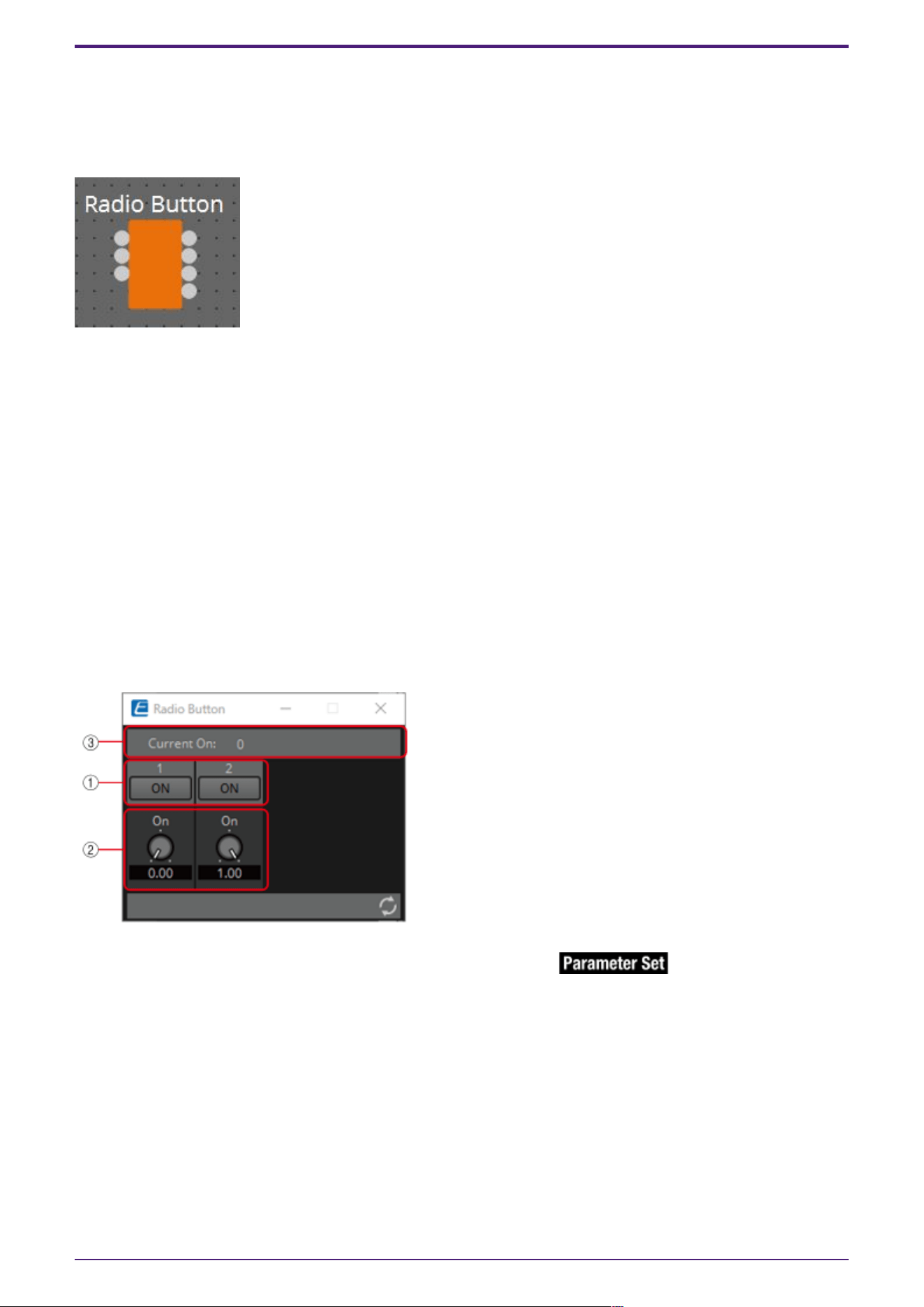
3.4. Input (Normalized Value): Radio Button
Only one of multiple buttons can be turned on. All buttons can be turned off. When a button is
switched to on, the channel number of the button that turned on and the specified value (normalized
value) are output.
(For 2 inputs)
INPUT
1: Input value to control button 1 (OFF:0, ON:1)
2: Input value to control button 2 (OFF:0, ON:1)
Sel: Specifies the button number to turn on (*)
OUTPUT
1: Outputs 1 when button 1 is turned ON and 0 when button 1 is turned OFF.
2: Outputs 1 when button 2 is turned ON and 0 when button 2 is turned OFF.
Out: Outputs the set value of the location where the button has been turned ON.
Sel: Number of the button that has turned on (*)
* is displayed when the Parameters Control PINs are checked.
3.4.1. “Radio Button” component editor
① When the button is switched on, the value set in ② is output.
② 0.00–1.00
③ Displays the channel number for which the button has turned on. If all of them are off, "0" will be
displayed.
3. Control Components
128 | ProVisionaire Design Component Guide

Parameter types of the input/output values for each Port
Operation Output Value
Input Port
Name
Trigger/Proces
sing
Output Port
Name
Type Range
● CH (1,2..) Trigger: Radio
Button
● CH (1,2..) Normalized
OFF:0,
ON:1
- ● Out Value Num 0.00–1.00
● Sel ● Sel Value Num 1–256
* Input Port: It is also possible to control the ON button by inputting OFF:0 and ON:1 in the Value
(Num) data type for CH.
* Input Port: It is also possible to control the ON button by inputting the CH number in the Value
(Num) data type for Sel.
3. Control Components
ProVisionaire Design Component Guide | 129
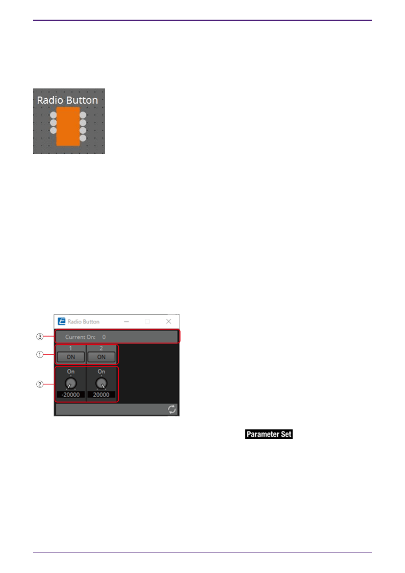
3.5. Input (Value): Radio Button
Only one of multiple buttons can be turned on. All buttons can be turned off. When a button is
switched to on, the channel number of the button that turned on and the specified value are output.
The type of output value (Num or dB) can be selected in the dialog that is displayed when the
component is placed.
(For 2 inputs)
INPUT
1: Input value to control button 1 (OFF:0, ON:1)
2: Input value to control button 2 (OFF:0, ON:1)
Sel: Specifies the button number to turn on (*)
OUTPUT
1: Outputs 1 when button 1 is turned on and 0 when button 1 is turned off
2: Outputs 1 when button 2 is turned on and 0 when button 2 is turned off
Out: Outputs the set value of the location where the button has been turned on
Sel: Number of the button that has turned on (*)
* is displayed when the Parameters Control PINs are checked.
3.5.1. ”Radio Button” component editor (Num)
① When the button is switched on, the value set in ② is output.
② –20,000 to 20,000
③ Displays the channel number for which the button has turned on. If all of them are off, "0" will be
displayed.
3. Control Components
130 | ProVisionaire Design Component Guide
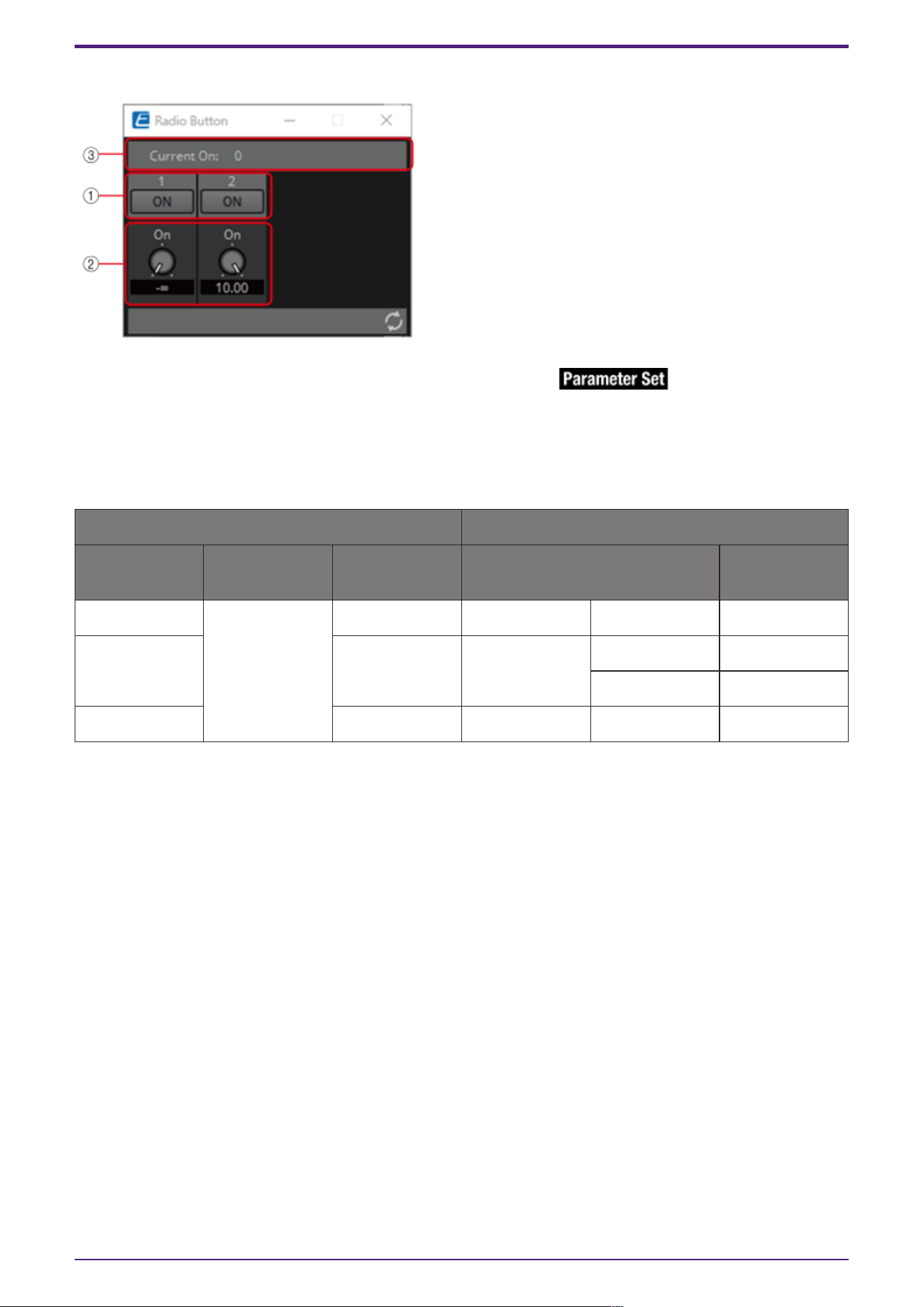
3.5.2. ”Radio Button” component editor (dB)
① When the button is switched on, the value set in ② is output.
② −∞ to 10 dB
③ Displays the channel number for which the button has turned on. If all of them are off, "0" will be
displayed.
Parameter types of the input/output values for each Port
Operation Output Value
Input Port
Name
Trigger/Proces
sing
Output Port
Name
Type Range
● CH (1,2..) Trigger: Radio
Button
● CH (1,2..) Value Num OFF:0 ON:1
- ● Out Value dB −∞–10.00
Num -20000–20000
● Sel ● Sel Value Num 1-256
* Input Port: It is also possible to control the ON button by inputting OFF:0 and ON:1 in the Value
(Num) data type for CH.
* Input Port: It is also possible to control the ON button by inputting the CH number in the Value
(Num) data type for Sel.
3. Control Components
ProVisionaire Design Component Guide | 131
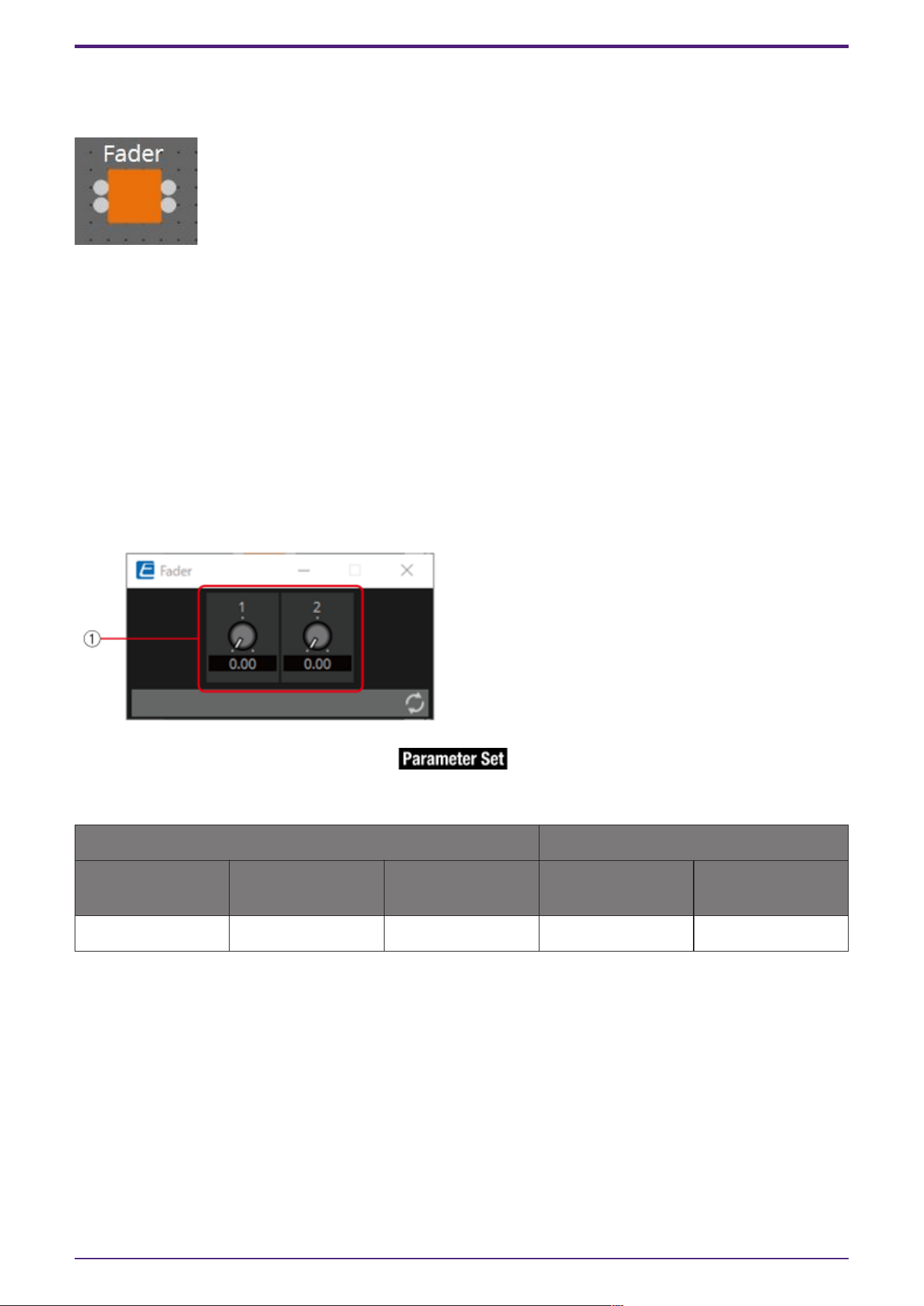
3.6. Input (Normalized Value): Fader
Continuous values (normalized values) are output by adjusting the controller.
(For 2 inputs)
INPUT
Value 1: Input value to control knob 1 (0.00–1.00)
Value 2: Input value to control knob 2 (0.00–1.00)
OUTPUT
Value 1: Output value when knob 1 is operated (0.00–1.00)
Value 2: Output value when knob 2 is operated (0.00–1.00)
The knob can also be controlled by an input signal (0.00–1.00).
3.6.1. ”Fader” component editor
① Outputs a normalized value (0.00–1.00).
Parameter types of the input/output values for each Port
Operation Output Value
Input Port Name Trigger/Processin
g
Output Port Name Type Range
● Value1 Trigger: Fader ● Value1 Normalized 0.00–1.00
* It is also possible to control the controller by entering numerical values for Value (Num), Value (dB),
and Normalized Value to the Input Port.
3. Control Components
132 | ProVisionaire Design Component Guide
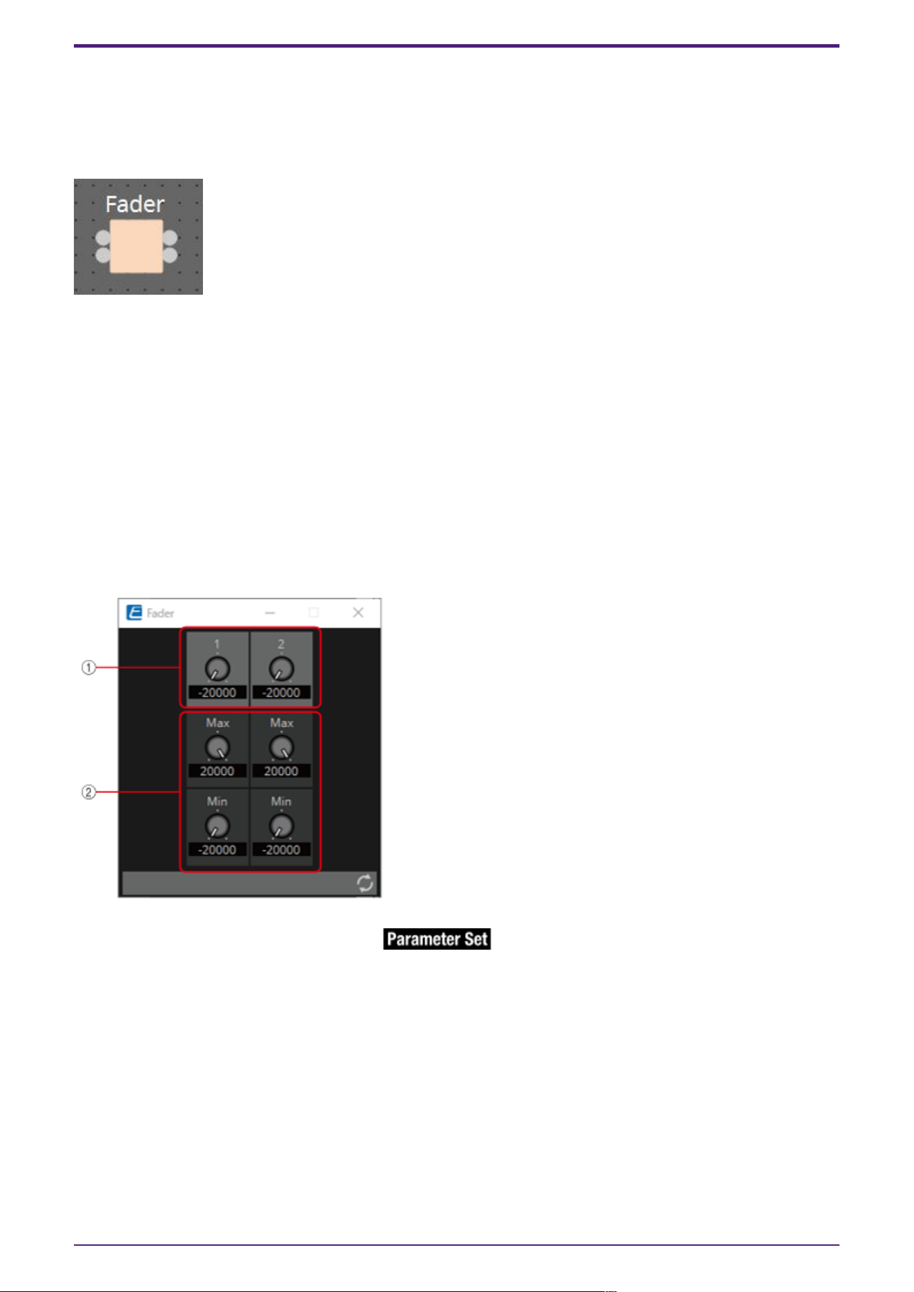
3.7. Input (Value): Fader
Continuous values are output by adjusting the controller.
The type of output value (Num or dB) can be selected in the dialog that is displayed when the
component is placed.
(For 2 inputs)
INPUT
Value1: Input value to control knob 1 (–20,000 to 20,000), (−∞ to 10.00)
Value2: Input value to control knob 2 (–20,000 to 20,000), (−∞ to 10.00)
OUTPUT
Value1: Output value when knob 1 is operated (–20,000 to 20,000), (−∞ to 10.00)
Value2: Output value when knob 2 is operated (–20,000 to 20,000), (−∞ to 10.00)
The knob can also be controlled by an input signal (–20,000 to 20,000), (−∞ to 10.00).
3.7.1. ”Fader” component editor (Num)
① Outputs a value of –20,000 to 20,000.
② MAX and MIN specify the fader operation range (–20,000 to 20,000).
3. Control Components
ProVisionaire Design Component Guide | 133
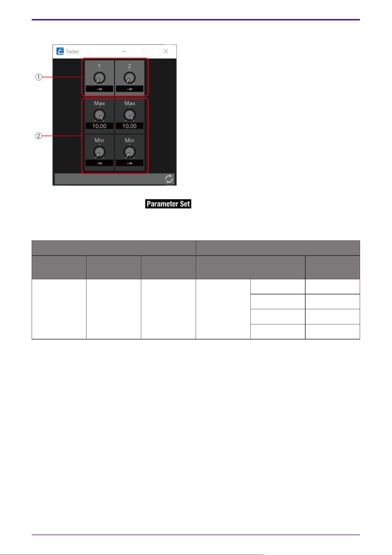
3.7.2. ”Fader” component editor (dB)
① Outputs a value of −∞ to 10.00.
② MAX and MIN specify the fader operation range (−∞ to 10.00).
Parameter types of the input/output values for each Port
Operation Output Value
Input Port
Name
Trigger/Proces
sing
Output Port
Name
Type Range
● Value1 Trigger: Fader ● Value1 Value Num -20000–20000
dB ∞–10.00
Num -20000–20000
dB −∞–10.00
* It is also possible to control the knob from ① by entering numerical values for Value (Num), Value
(dB), and Normalized Value to the Input Port.
3. Control Components
134 | ProVisionaire Design Component Guide
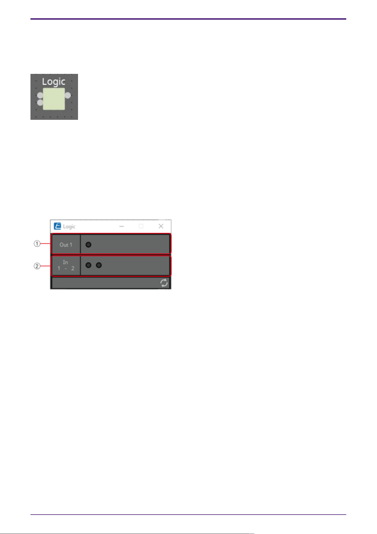
3.8. Processing (Normalized Value): Logic
This is the basic circuit component.
AND, NAND, OR, NOR, XOR, NOT XOR or 1 of N can be selected in the dialog that is displayed when the
component is placed.
(For 2 inputs)
INPUT
1: Input value 1 to Logic (OFF:0, ON:1)
2: Input value 2 to Logic (OFF:0, ON:1)
OUTPUT
Out: Logic process results (OFF:0, ON:1)
3.8.1. ”Logic” component editor
① Input signals can be checked.
② Output signals (process results) can be checked.
3.8.2. ”Logic” component editor (AND)
When all of the inputs are 1, then the output is 1.
If any 1 of the inputs is 0, then the output is 0.
If the input and output are 0, the indicator is off, and if the input and output are 1, the indicator is
on.
3.8.3. ”Logic” component editor (NAND)
When all of the inputs are 1, then the output is 0.
If any 1 of the inputs is 0, then the output is 1.
If the input and output are 0, the indicator is off, and if the input and output are 1, the indicator is
on.
3. Control Components
ProVisionaire Design Component Guide | 135
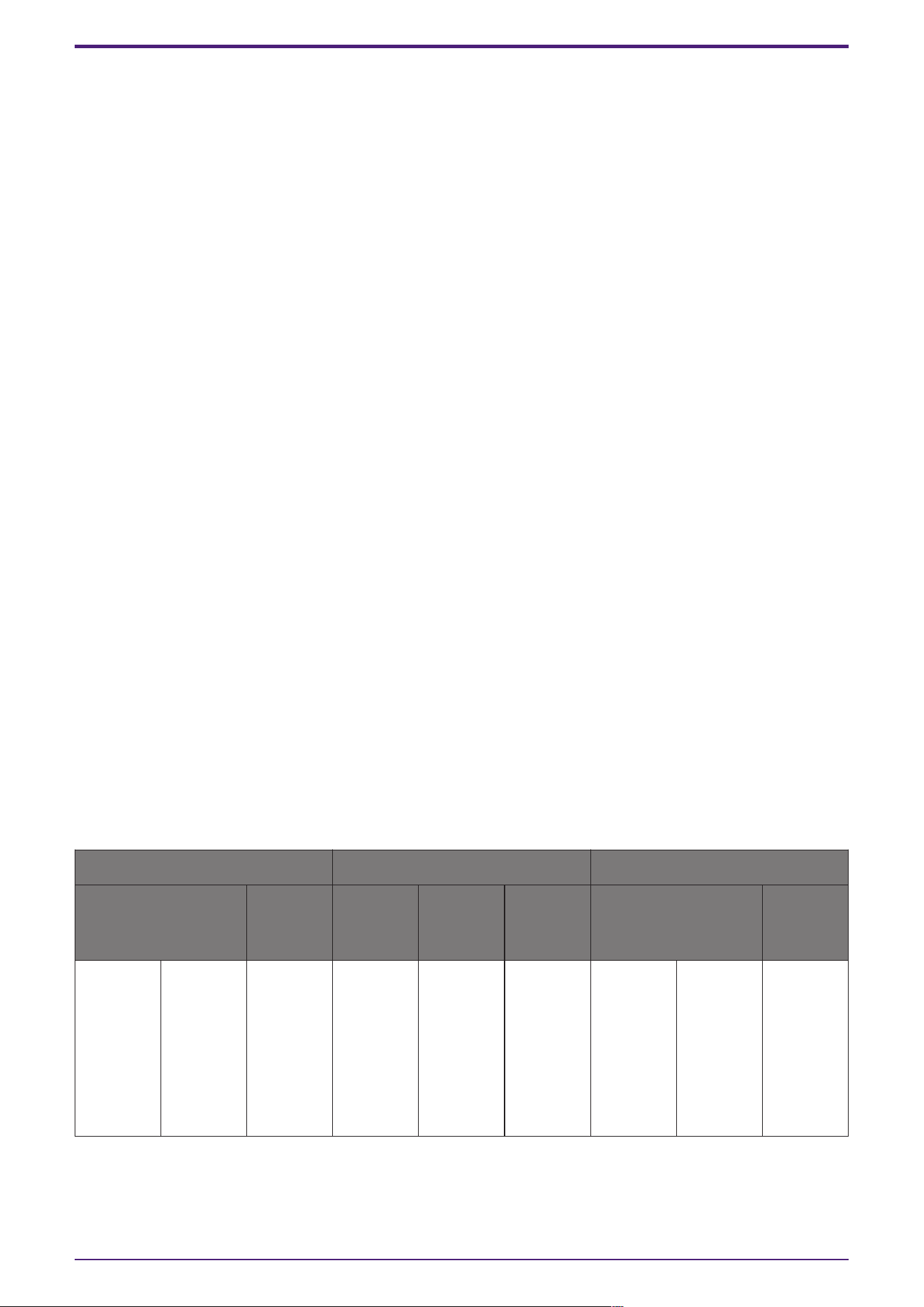
3.8.4. ”Logic” component editor (OR)
When all of the inputs are 0, then the output is 0.
If any 1 of the inputs is 1, then the output is 1.
If the input and output are 0, the indicator is off, and if the input and output are 1, the indicator is
on.
3.8.5. ”Logic” component editor (NOR)
When all of the inputs are 0, then the output is 1.
If any 1 of the inputs is 1, then the output is 0.
If the input and output are 0, the indicator is off, and if the input and output are 1, the indicator is
on.
3.8.6. ”Logic” component editor (XOR)
When the number of 1 inputs is odd, the output is 1.
When the number of 1 inputs is even, the output is 0.
If the input and output are 0, the indicator is off, and if the input and output are 1, the indicator is
on.
3.8.7. ”Logic” component editor (NOT XOR)
When the number of 1 inputs is even, the output is 1.
When the number of 1 inputs is odd, the output is 0.
If the input and output are 0, the indicator is off, and if the input and output are 1, the indicator is
on.
3.8.8. ”Logic” component editor (1 of N)
If any 1 of the inputs is 1, then the output is 1.
If any 2 or more of the inputs are 1, then the output is 0.
If the input and output are 0, the indicator is off, and if the input and output are 1, the indicator is
on.
Parameter types of the input/output values for each Port
Input Value Operation Output Value
Type Range Input
Port
Name
Trigger/P
rocessing
Output
Port
Name
Type Range
Value Num
OFF:0,
ON:1
● CH
(1,2..)
Processin
g: Logic
(AND,
NAND,
OR, NOR,
XOR, NOT
XOR, 1 of
N)
● Out Value Num
OFF:0,
ON:1
3. Control Components
136 | ProVisionaire Design Component Guide
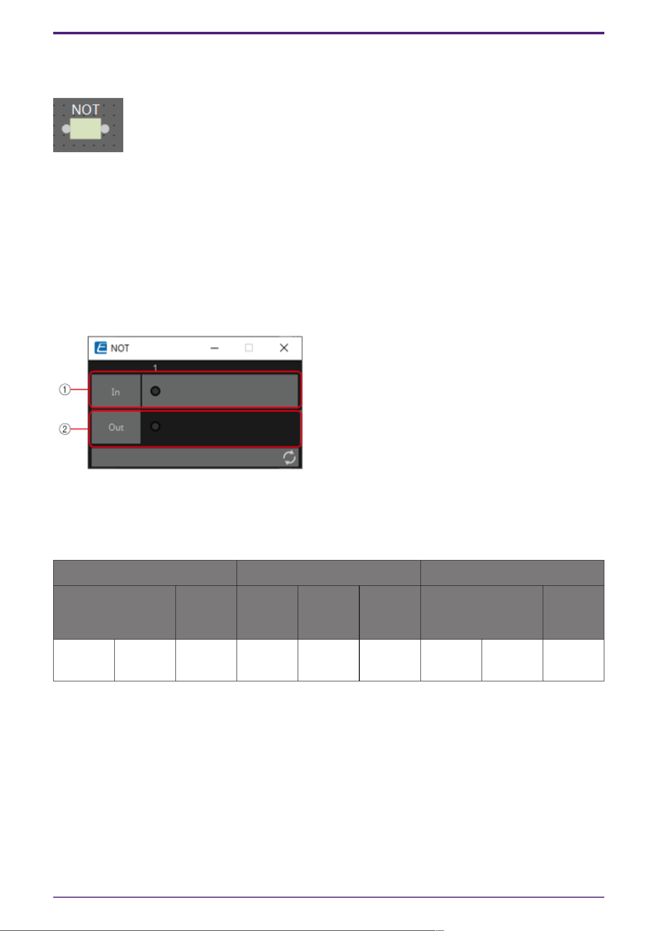
3.9. Processing (Normalized Value): NOT
This component inverts the input value.
INPUT
1: Input value (OFF:0, ON:1)
OUTPUT
Out1: NOT process results (OFF:0, ON:1)
If the input value is 1, then the output is 0.
If the input value is 0, then the output is 1.
3.9.1. ”NOT” component editor
① On when the input value is 1, off when the input value is 0.
② On when the output value is 1, off when the output value is 0.
Parameter types of the input/output values for each Port
Input Value Operation Output Value
Type Range Input
Port
Name
Trigger/P
rocessing
Output
Port
Name
Type Range
Value Num
OFF:0,
ON:1
● CH
(1,2..)
Processin
g: NOT
● Out Value Num
OFF:0,
ON:1
3. Control Components
ProVisionaire Design Component Guide | 137
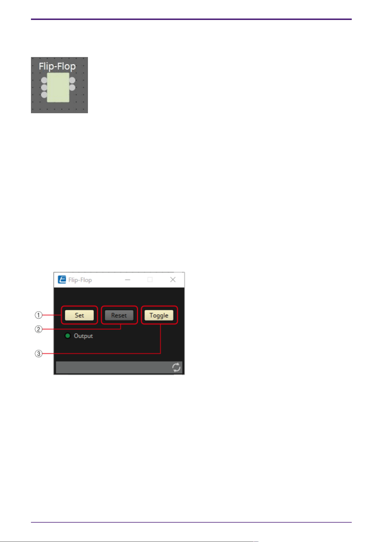
3.10. Processing (Normalized Value): Flip-Flop
This component is used to enable toggle operation.
INPUT
Set: Trigger input to push the [Set] button*
Reset: Trigger input to push the [Reset] button*
Toggle: Trigger input to push the [Toggle] button*
*: Values that are input from an external source act as simple triggers that are not related to any
operation.
OUTPUT
Out: on/off state of the [Set] button (OFF:0, ON:1)
Not Out: Out inversion value
When the [Set] button is on, 1 is output from Out, and the Out inversion value is output from Not
Out.
When the [Reset] button is turned on, the [Set] button is turned off.
3.10.1. ”Flip-Flop” component editor
① When the [Set] button is turned on, the [Toggle] button also turns on, and the [Output] indicator
turns on.
② When the [Reset] button is turned on, the [Toggle] button turns off, and the [Output] indicator
turns off. 0 is output from Out, and 1 is output from Not Out.
③ When the [Toggle] button is pressed, it switches between on or off. When it is on, the [Set] button
runs the on process, and when it is off, the [Reset] button runs the on process.
3. Control Components
138 | ProVisionaire Design Component Guide
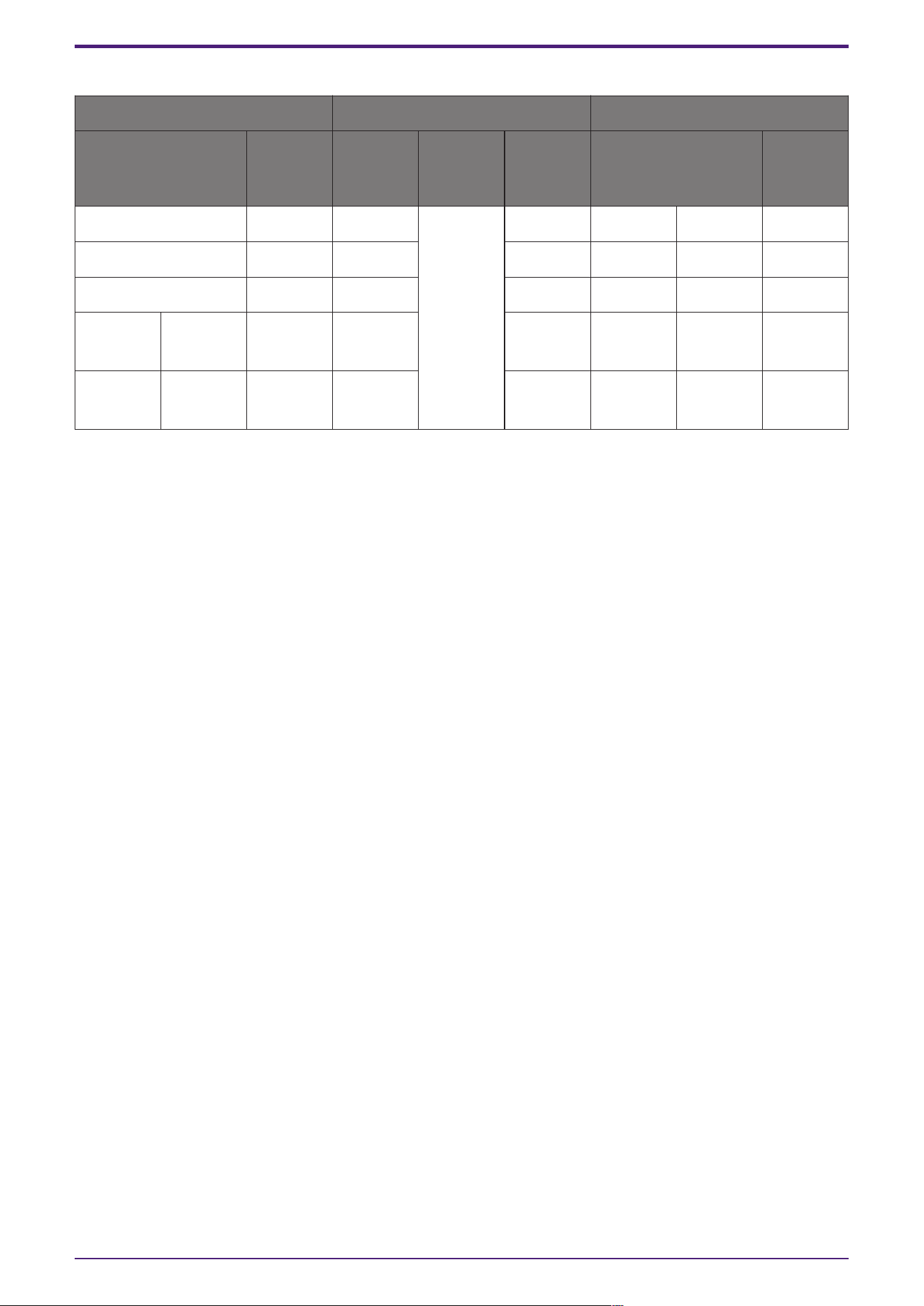
Parameter types of the input/output values for each Port
Input Value Operation Output Value
Type Range Input
Port
Name
Trigger/P
rocessing
Output
Port
Name
Type Range
Trigger Input - ● Set Processin
g: Flip-
Flop
- - - -
Trigger Input - ● Reset - - - -
Trigger Input - ● Toggle - - - -
- - - - ● Out Value Num
OFF:0,
ON:1
- - - - ●
NotOut
Value Num
OFF:0,
ON:1
3. Control Components
ProVisionaire Design Component Guide | 139
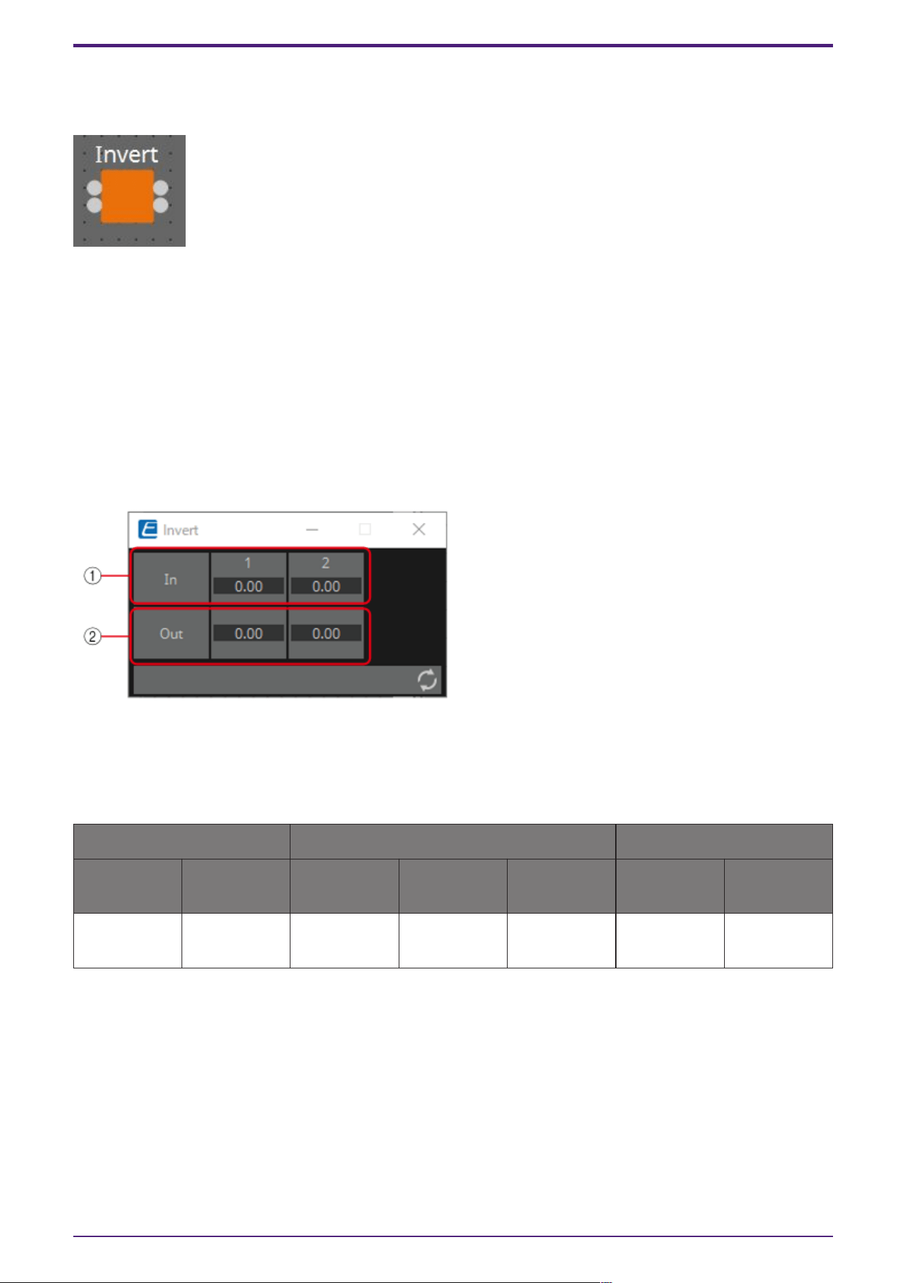
3.11. Processing (Normalized Value): Invert
This component calculates the maximum value of the normalized value (1.00) minus the input value.
(For 2 inputs)
INPUT
1: Channel 1 input value (0.00–1.00)
2: Channel 2 input value (0.00–1.00)
OUTPUT
Out1: 1.00 minus the channel 1 input value
Out2: 1.00 minus the channel 2 input value
3.11.1. ”Invert” component editor
① The input value (0.00–1.00) can be checked.
② 1.00 minus the input value ① is output as the value.
Parameter types of the input/output values for each Port
Input Value Operation Output Value
Type Range Input Port
Name
Trigger/Proc
essing
Output Port
Name
Type Range
Normalized 0.00–1.00 ● CH (1,2..) Processing:
Invert
● CH (1,2..) Normalized 0.00–1.00
3. Control Components
140 | ProVisionaire Design Component Guide
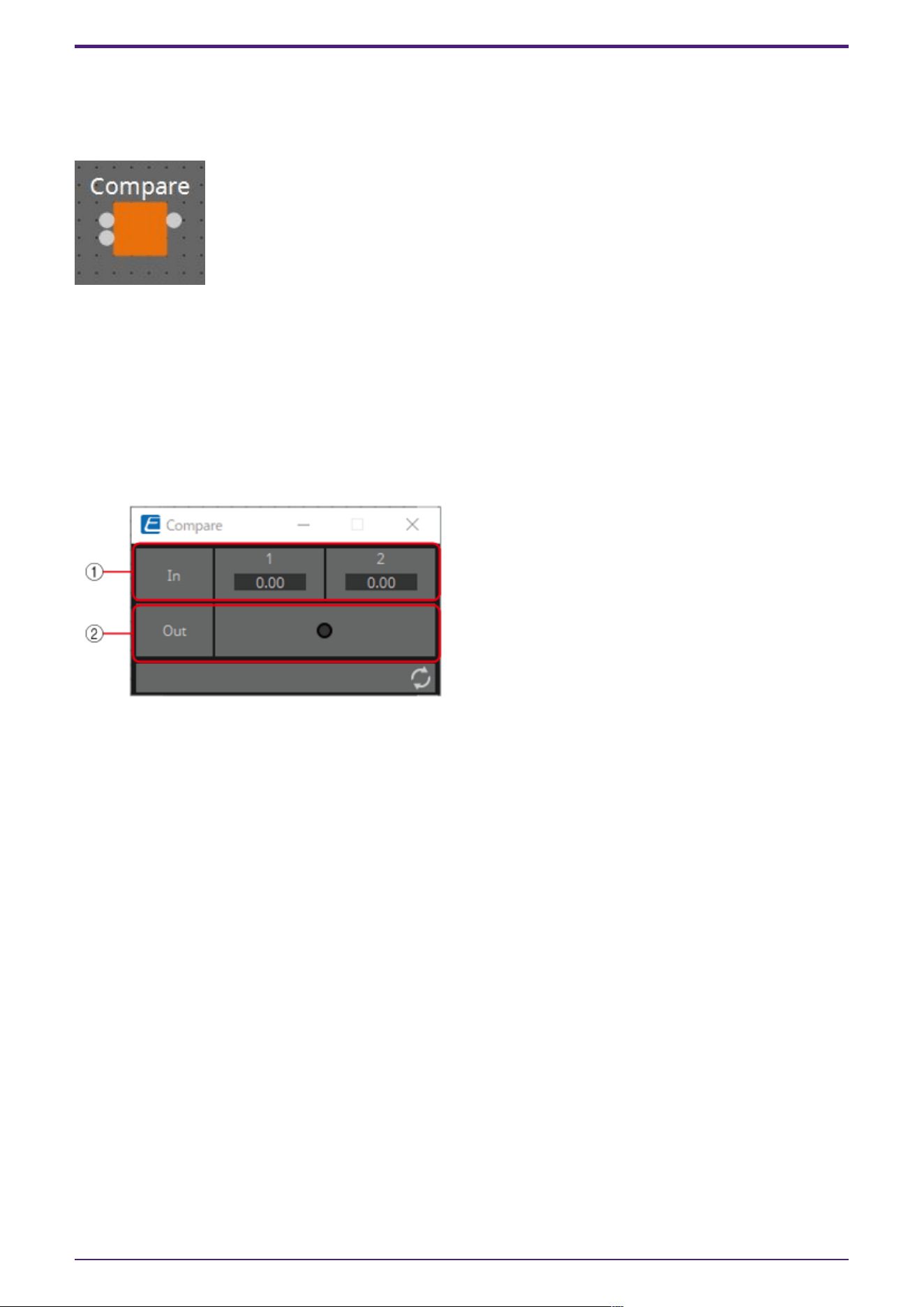
3.12. Processing (Normalized Value): Compare
This component is used to obtain the result of comparing two input values.
Greater, Less or Equal can be selected in the dialog that is displayed when the component is placed.
INPUT
1: Input value 1 (0.00–1.00)
2: Input value 2 (0.00–1.00)
OUTPUT
Out: Comparison result (0, 1)
3.12.1. ”Compare” component editor
① Input values can be checked. (0.00–1.00)
② Outputs the result of comparing two input values.
3.12.2. ”Compare” component editor (Greater)
When In1 > In2, 1 is output, and the Out indicator turns on.
For all other cases, 0 is output and the indicator turns off.
3.12.3. ”Compare” component editor (Less)
When In1 < In2, 1 is output, and the Out indicator turns on.
For all other cases, 0 is output and the indicator turns off.
3.12.4. ”Compare” component editor (Equal)
When In1 = In2, 1 is output, and the Out indicator turns on.
For all other cases, 0 is output and the indicator turns off.
3. Control Components
ProVisionaire Design Component Guide | 141

Parameter types of the input/output values for each Port
Input Value Operation Output Value
Type Range Input
Port
Name
Trigger/P
rocessing
Output
Port
Name
Type Range
Normalized 0.00–1.00 ● CH
(1,2)
Processin
g:
Compare
(Greater,
Less,
Equal)
- - - -
- - - - ● Out Value Num
OFF:0,
ON:1
3. Control Components
142 | ProVisionaire Design Component Guide
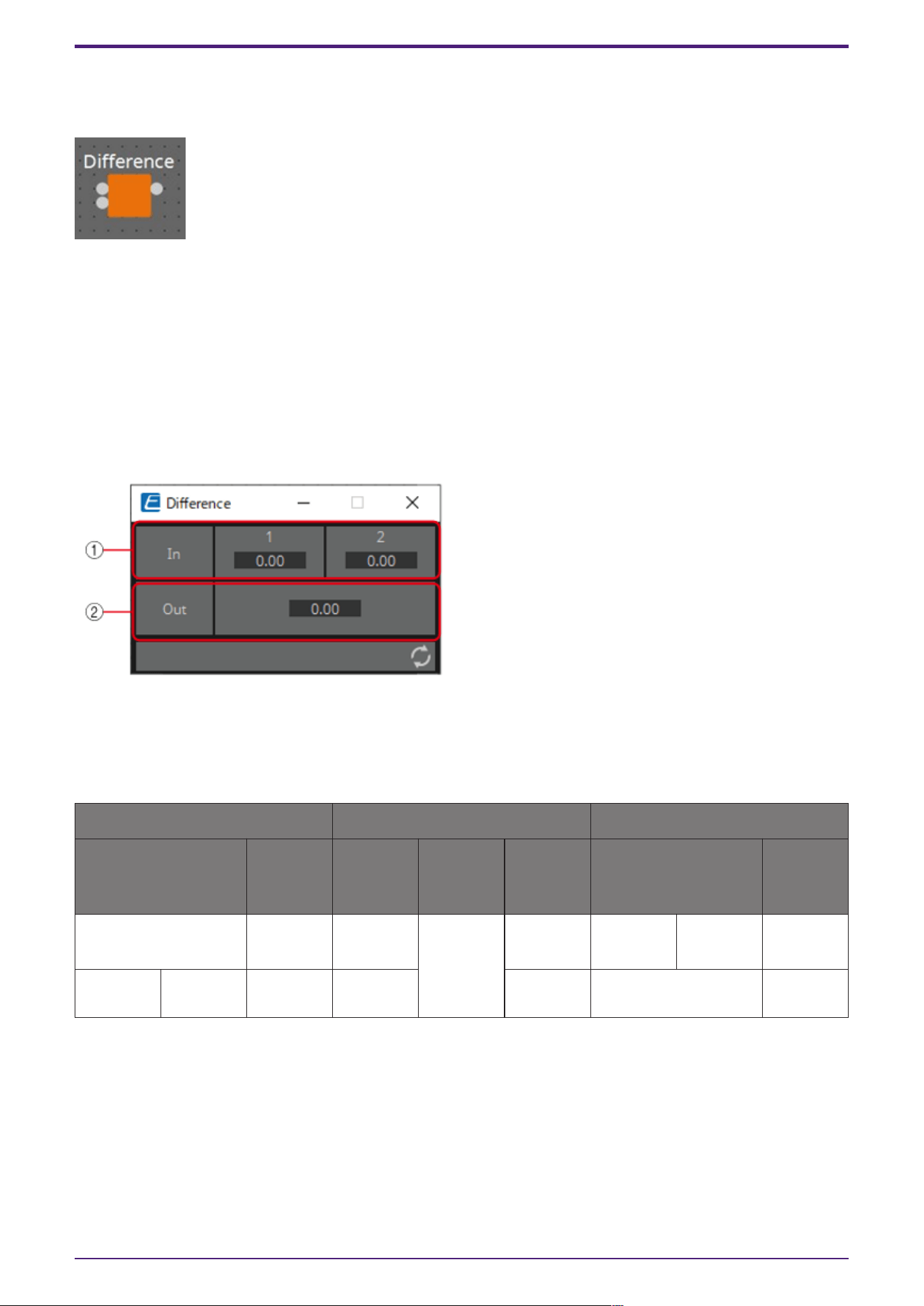
3.13. Processing (Normalized Value): Difference
This component is used to obtain the difference between two input values.
INPUT
1: Input value 1 (0.00–1.00)
2: Input value 2 (0.00–1.00)
OUTPUT
Out: The value of input 1 minus input 2
If the result of subtracting input value 2 from input value 1 is negative (minus), the result is 0.00.
3.13.1. ”Difference” component editor
① The input value (0.00–1.00) can be checked.
② Displays the value of subtracting input value 2 from input value 1.
Parameter types of the input/output values for each Port
Input Value Operation Output Value
Type Range Input
Port
Name
Trigger/P
rocessing
Output
Port
Name
Type Range
Normalized 0.00–1.00 ● CH
(1,2)
Processin
g:
Differenc
e
- - - -
- - - - ● Out Normalized 0.00–1.00
3. Control Components
ProVisionaire Design Component Guide | 143
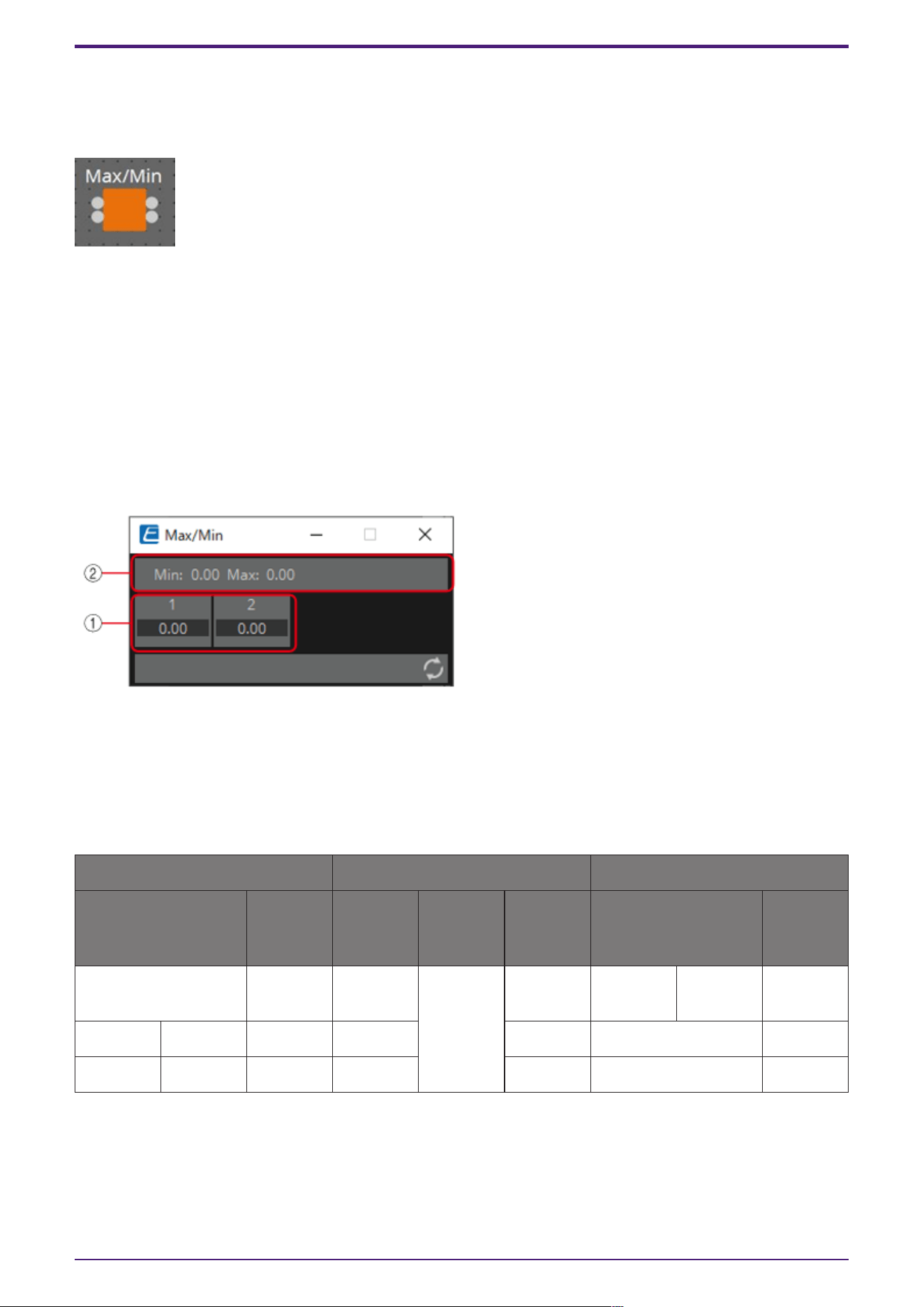
3.14. Processing (Normalized Value): Max/Min
This component detects and outputs the largest/smallest value of the values input from multiple
ports.
(For 2 inputs)
INPUT
1: Input value 1 (0.00–1.00)
2: Input value 2 (0.00–1.00)
OUTPUT
Max: The largest value from multiple input values (0.00–1.00)
Min: The smallest value from multiple input values (0.00–1.00)
3.14.1. ”Max/Min” component editor
① The input value (0.00–1.00) can be checked.
② The largest value (0.00 to 1.00) among all channel inputs is displayed as Max and output from the
Max port. The smallest value (0.00 to 1.00) among all channel inputs is displayed as Min and output
from the Min port.
Parameter types of the input/output values for each Port
Input Value Operation Output Value
Type Range Input
Port
Name
Trigger/P
rocessing
Output
Port
Name
Type Range
Normalized 0.00–1.00 ● CH
(1,2..)
Processin
g:
Max/Min
- - - -
- - - - ● Max Normalized 0.00–1.00
- - - - ● Min Normalized 0.00–1.00
3. Control Components
144 | ProVisionaire Design Component Guide
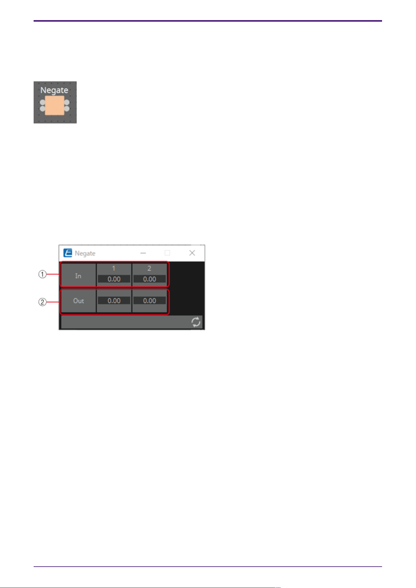
3.15. Processing (Value): Negate
This component performs arithmetic operations on input values.
Negate, Square, Square Root or Absolute can be selected in the dialog that is displayed when the
component is placed.
(For 2 inputs)
INPUT
1: Channel 1 input value (–20,000 to 20,000), (−∞ to 10.00)
2: Channel 2 input value (–20,000 to 20,000), (−∞ to 10.00)
OUTPUT
1: Calculation results for channel 1 input values
2: Calculation results for channel 2 input values
3.15.1. ”Negate” component editor
① Input signals can be checked.
② Output signals (process results) can be checked.
3.15.2. ”Negate” component editor (Negate)
Outputs the inverted positive/negative value of the input value.
3.15.3. “Negate” component editor (Square)
Outputs the square of the input value.
3.15.4. “Negate” component editor (Square Root)
Outputs the square root of the input value.
3.15.5. “Negate” component editor (Absolute)
Outputs the absolute value of the input value.
3. Control Components
ProVisionaire Design Component Guide | 145

Parameter types of the input/output values for each Port
Input Value Operation Output Value
Type Range Input Port
Name
Trigger/Pr
ocessing
Output
Port Name
Type Range
Value Num -20000–20
000
● CH
(1,2..)
Processing
: Negate,
Square,
Square
Root,
Absolute
● CH
(1,2..)
Actual Value
dB −∞–10.00
3. Control Components
146 | ProVisionaire Design Component Guide
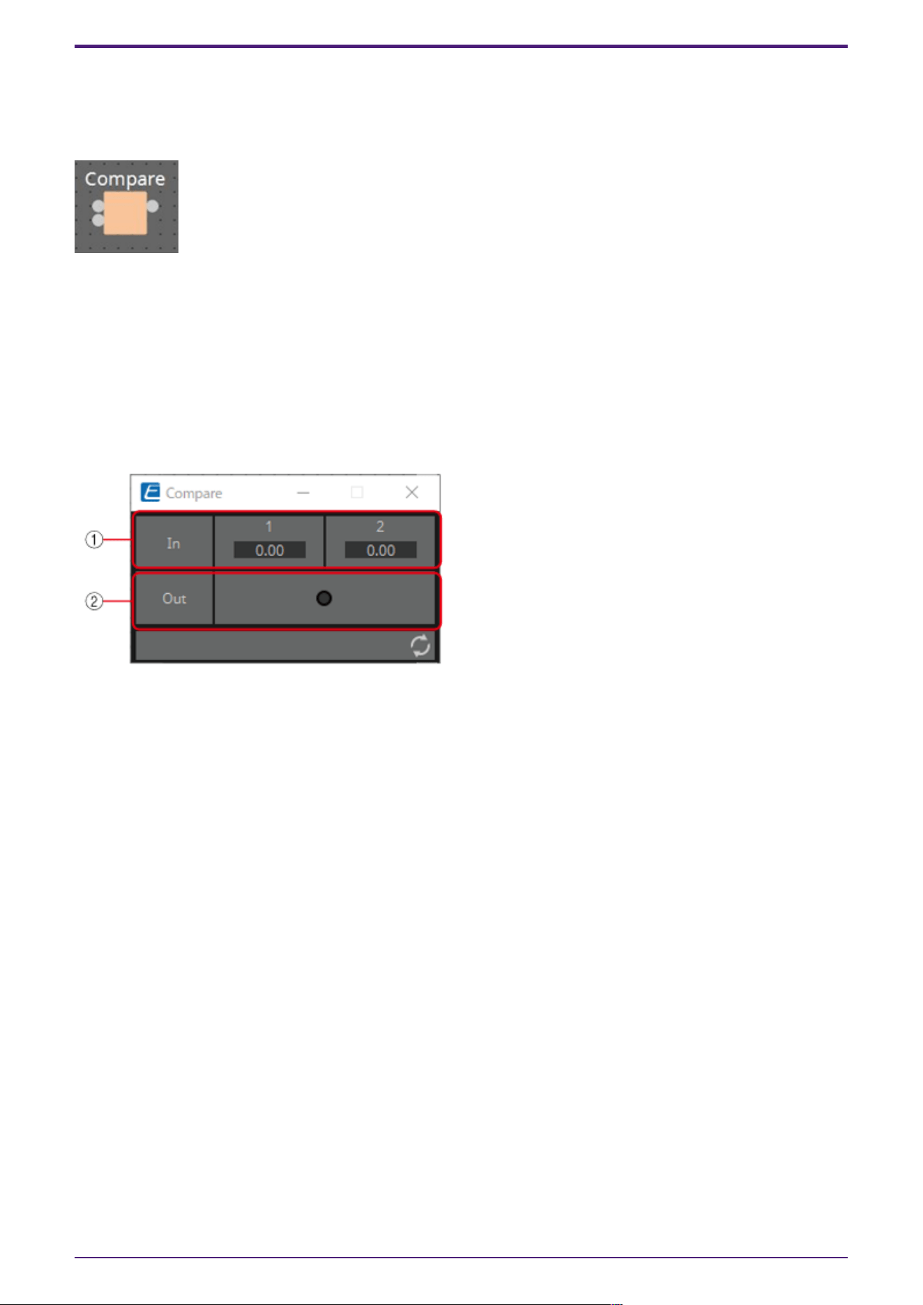
3.16. Processing (Value): Compare
This component is used to obtain the result of comparing two input values.
Greater, Less or Equal can be selected in the dialog that is displayed when the component is placed.
INPUT
1: Input value 1 (–20,000 to 20,000), (−∞ to 10.00)
2: Input value 2 (–20,000 to 20,000), (−∞ to 10.00)
OUTPUT
Out: Comparison result (0, 1)
3.16.1. ”Compare” component editor
① Input values can be checked.
② Outputs the result of comparing two input values.
3.16.2. ”Compare” component editor (Greater)
When In1 > In2, 1 is output, and the Out indicator turns on.
For all other cases, 0 is output and the indicator turns off.
3.16.3. ”Compare” component editor (Less)
When In1 < In2, 1 is output, and the Out indicator turns on.
For all other cases, 0 is output and the indicator turns off.
3.16.4. ”Compare” component editor (Equal)
When In1 = In2, 1 is output, and the Out indicator turns on.
For all other cases, 0 is output and the indicator turns off.
3. Control Components
ProVisionaire Design Component Guide | 147

Parameter types of the input/output values for each Port
Input Value Operation Output Value
Type Range Input
Port
Name
Trigger/P
rocessing
Output
Port
Name
Type Range
Value Num -20000–2
0000
● CH
(1,2..)
Processin
g:
Compare
(Greater,
Less,
Equal)
- - - -
dB −∞–10.00 - - - -
- - - - ● Out Value Num
OFF:0,
ON:1
3. Control Components
148 | ProVisionaire Design Component Guide
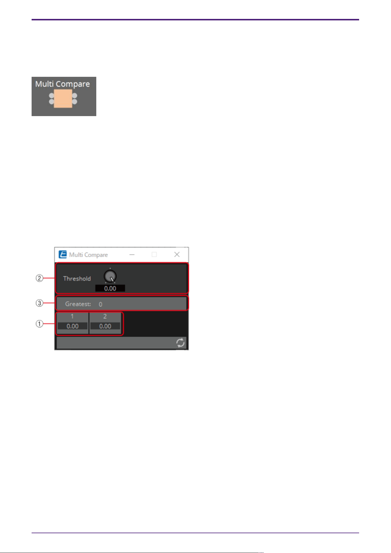
3.17. Processing (Value): Multi Compare
This component compares the input values from multiple ports and detects the channel number with
the largest/smallest input value.
Greatest or Smallest can be selected in the dialog that is displayed when the component is placed.
(For 2 inputs)
INPUT
1: Input value 1 (–20,000 to 20,000), (−∞ to 10.00)
2: Input value 2 (–20,000 to 20,000), (−∞ to 10.00)
OUTPUT
Out 1: Outputs ON:1 when the channel 1 input value is the largest/smallest value. Outputs 0 for all
other cases.
Out 2: Outputs ON:1 when the channel 2 input value is the largest/smallest value. Outputs 0 for all
other cases.
3.17.1. “Multi Compare” component editor
① Input signals can be checked.
② Threshold value
③ Displays the result (channels with the largest/smallest input values) of comparing multiple input
values that exceed the Threshold value.
3.17.2. “Multi Compare” component editor (Greatest)
Compares input values greater than the Threshold value and outputs 1 from the channel determined to
have the largest value. All other channels output 0.
3.17.3. “Multi Compare” component editor (Smallest)
Compares input values smaller than the Threshold value and outputs 1 from the channel determined to
have the smallest value. All other channels output 0.
3. Control Components
ProVisionaire Design Component Guide | 149

Parameter types of the input/output values for each Port
Input Value Operation Output Value
Type Range Input
Port
Name
Trigger/P
rocessing
Output
Port
Name
Type Range
Value Num -20000–2
0000
● CH
(1,2..)
Processin
g : Multi
Compare (
Greatest,
Smallest )
● CH
(1,2..)
Value Num
OFF:0,
ON:1
dB −∞–10.00
3. Control Components
150 | ProVisionaire Design Component Guide
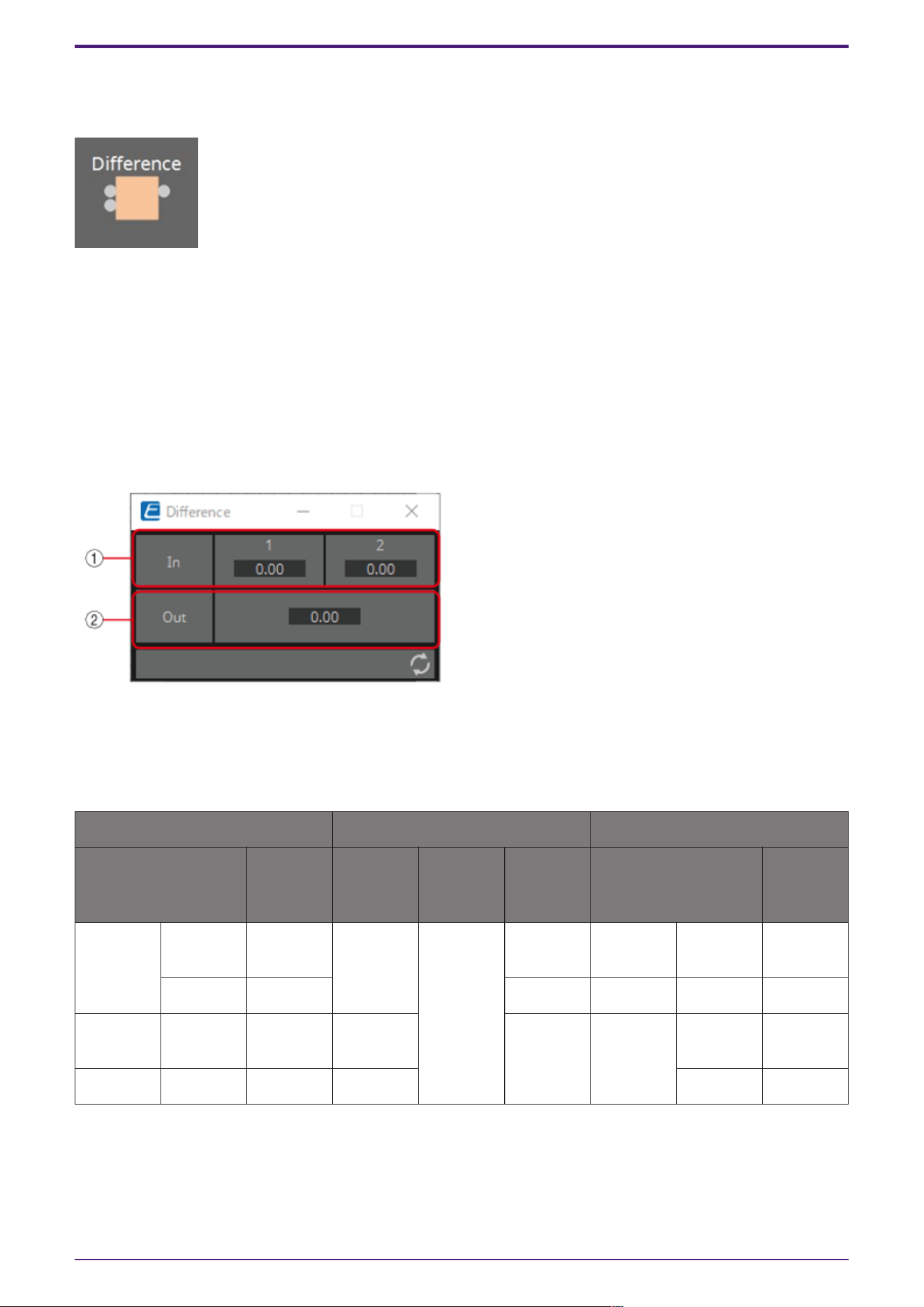
3.18. Processing (Value): Difference
This component is used to obtain the difference between two input values.
INPUT
1: Input value 1 (–20,000 to 20,000), (−∞ to 10.00)
2: Input value 2 (–20,000 to 20,000), (−∞ to 10.00)
OUTPUT
Out: The value of input 1 minus input 2
If the result of subtracting input value 2 from input value 1 is negative (minus), the result is 0.00.
3.18.1. “Difference” component editor
① Input signals can be checked.
② Displays the value of subtracting input value 2 from input value 1.
Parameter types of the input/output values for each Port
Input Value Operation Output Value
Type Range Input
Port
Name
Trigger/P
rocessing
Output
Port
Name
Type Range
Value Num -20000–2
0000
● CH
(1,2)
Processin
g:
Differenc
e
- - - -
dB −∞–10.00 - - - -
- - - - ● Out Value Num -20000–2
0000
- - - - dB −∞–10.00
3. Control Components
ProVisionaire Design Component Guide | 151
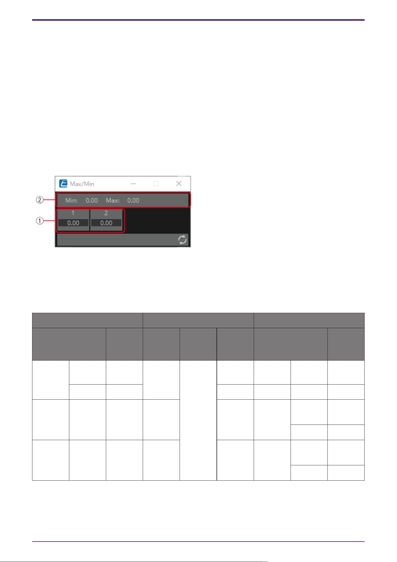
3.19. Processing (Value): Max/Min
This component detects and outputs the largest/smallest value of the values input from multiple
ports.
(For 2 inputs)
INPUT
1: Input value 1 (–20,000 to 20,000), (−∞ to 10.00)
2: Input value 2 (–20,000 to 20,000), (−∞ to 10.00)
OUTPUT
Max: The largest value from multiple input values
Min: The smallest value from multiple input values
3.19.1. ”Max/Min” component editor
① The input value (0.00–1.00) can be checked.
② The largest value among all channel inputs is displayed as Max and output from the Max port.
The smallest value among all channel inputs is displayed as Min and output from the Min port.
Parameter types of the input/output values for each Port
Input Value Operation Output Value
Type Range Input
Port
Name
Trigger/P
rocessing
Output
Port
Name
Type Range
Value Num -20000–2
0000
● CH
(1,2..)
Processin
g:
Max/Min
- - - -
dB −∞–10.00 - - - -
- - - - ● Max Value Num
OFF:0,
ON:1
dB −∞–10.00
- - - - ● Min Value Num
OFF:0,
ON:1
dB −∞–10.00
3. Control Components
152 | ProVisionaire Design Component Guide
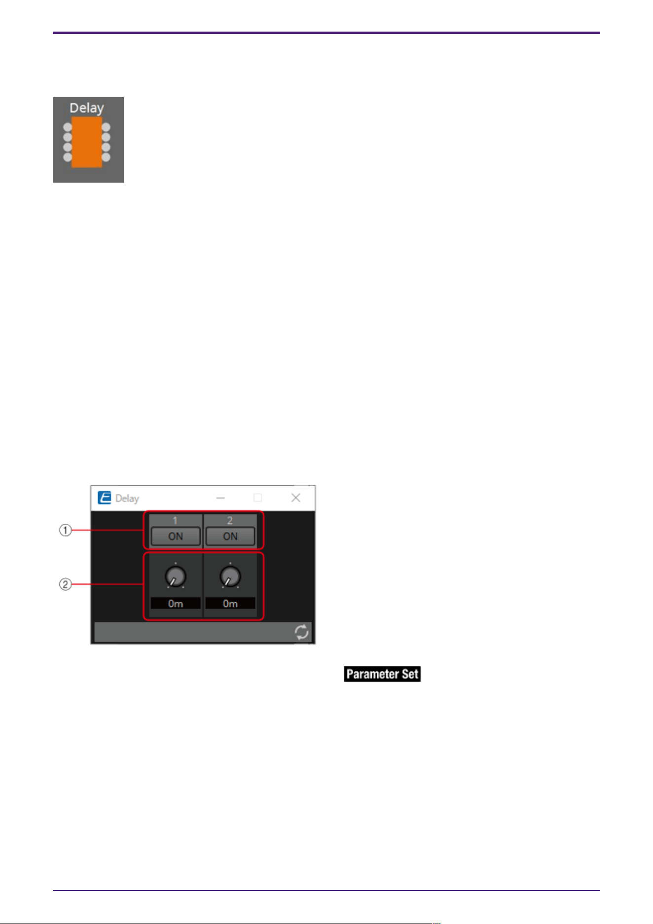
3.20. Processing: Delay
This component can delay the input signal before outputting it.
(For 2 inputs)
INPUT
1: Channel 1 input value
2: Channel 2 input value
On1: Input value to control the channel 1 button (OFF:0, ON:1) (*)
On2: Input value to control the channel 2 button (OFF:0, ON:1) (*)
OUTPUT
1: Channel 1 input value
2: Channel 2 input value
On 1: Output value when the channel 1 button is switched (OFF:0, ON:1) (*)
On 2: Output value when the channel 2 button is switched (OFF:0, ON:1) (*)
* is displayed when the Parameters Control PINs are checked.
If the delay time is 0 msec, the input signal is output through without change.
3.20.1. “Delay” component editor
① Switches the enable/disable for the Delay function.
② When any value is input to the channel input, that input value is then output with a delay of the
specified delay time (0 ms to 60.00 s).
It can be delayed only when in the ON state.
3. Control Components
ProVisionaire Design Component Guide | 153

Parameter types of the input/output values for each Port
Input Value Operation Output Value
Type Range Input
Port
Name
Trigger/P
rocessing
Output
Port
Name
Type Range
Through ● CH
(1,2..)
Processin
g: Delay
● CH
(1,2..)
Same value as the Input Value
Value Num
OFF:0,
ON:1
● ON
(1,2..)
● ON
(1,2..)
Value Num
OFF:0,
ON:1
3. Control Components
154 | ProVisionaire Design Component Guide
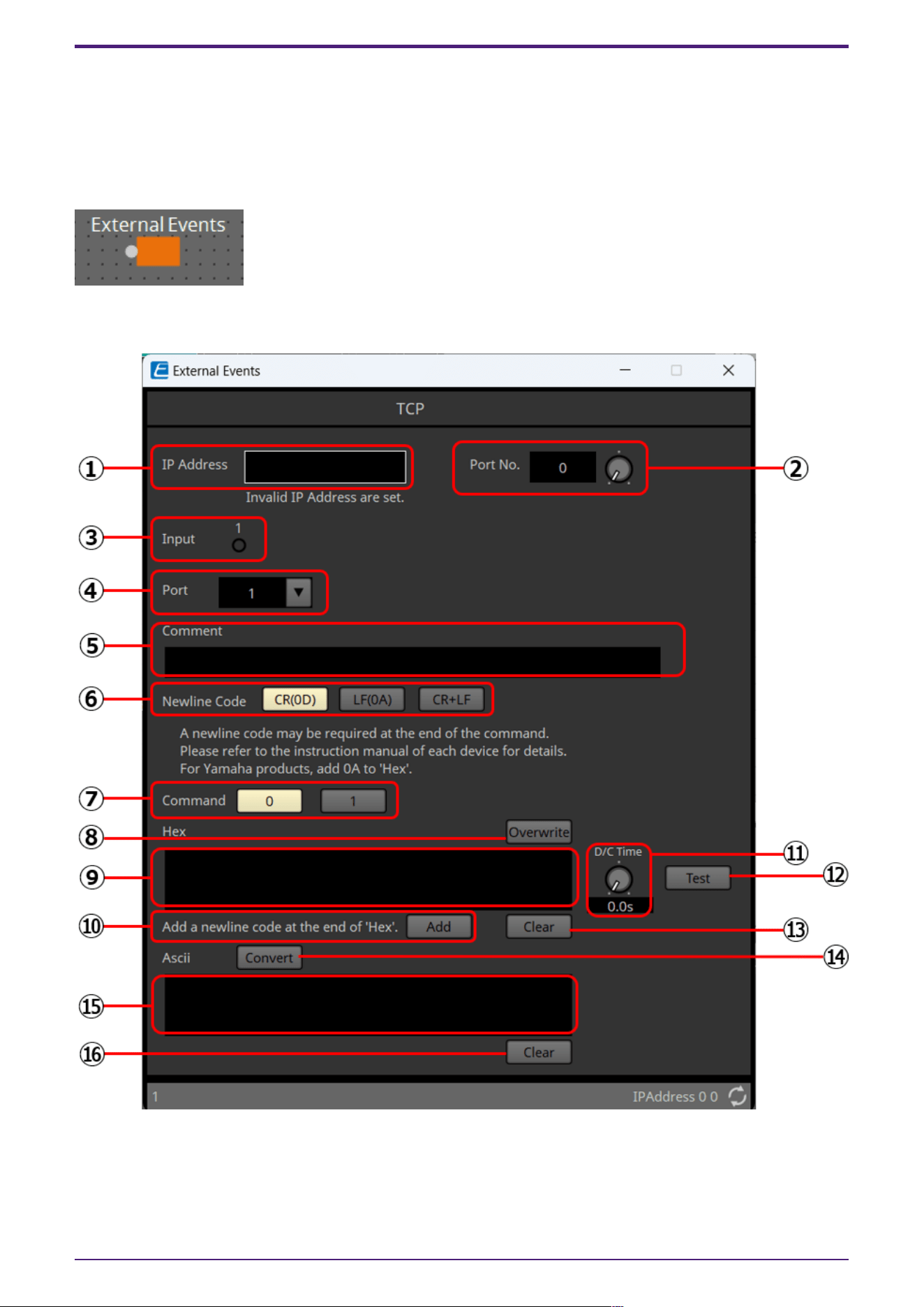
3.21. Processing: External Events
Configures the command to send to the network using the input of 0 or 1 to an input port as a trigger.
One External event can be set for 1 input port.
A maximum of 16 External events can be set within a component.
The protocol (TCP, UDP) can be selected in the dialog that is displayed when the component is placed.
3.21.1. ”External Events” component editor
① [IP Address] text box
Sets the IP address for the device that will receive the command.
② [Port No.] text box/knob
Sets the port number for the device that will receive the command.
3. Control Components
ProVisionaire Design Component Guide | 155

③ [Input] indicator
Displays the status of the signals input to each input port. The indicator turns off when "0" is input,
and turns on when "1" is input.
④ [Port] list box
Selects the target for editing.
⑤ [Comment] text box
Allows for input of text. For example, it can be used to enter a description of an event to make it
easier to identify.
⑥ Newline Code [CR(0D)]/[LF(0A)]/[CR+LF] button
Select a newline code to be inserted when a newline is added by "Add a newline code at the end of
‘Hex’." in [Hex] or a newline is started while [Ascii] editing is being performed.
CR is 0x0D, LF is 0x0A, and CR+LF is 0x0D 0x0A.
⑦ [Command] button
When 0 is selected, the command that will be sent when 0 is input to the input port will be edited in
the [Hex] text box.
When 1 is selected, the command that will be sent when 1 is input to the input port will be edited in
the [Hex] text box.
⑧ [Overwrite] button
When this has been set to on, the [Hex] text box is overwritten. Turn off to insert.
⑨ [Hex] text box
The command can be entered in hexadecimal.
⑩ Add a newline code at the end of ‘Hex’. [Add] button
Adds a newline code to the end of the displayed command.
⑪ D/C(Disconnection Delay) Time knob(TCP command only)
Sets the time to wait before the session with the connected device is disconnected after a command is
sent.
Adjust this setting when you have difficulty in controlling your device.
⑫ [Test] button
The command entered in the [Hex] text box is sent directly from ProVisionaire Design.
⑬ [Hex] Clear button
Deletes the contents of the [Hex] text box.
⑭ [Convert] button
Converts the text string command entered in the [Ascii] text box into hexadecimal, and reflects it in
the [Hex] text box.
⑮ [Ascii] text box
The command can be entered as a text string.
⑯ [Ascii] Clear button
Deletes the contents of the [Ascii] text box.
3. Control Components
156 | ProVisionaire Design Component Guide

3.22. Processing: Suspend
This is a control component to temporarily stop the output of the input signal.
(For 2 inputs)
INPUT
1: Channel 1 input value
2: Channel 2 input value
On1: Input value to control the channel 1 button (OFF:0, ON:1) (*)
On2: Input value to control the channel 2 button (OFF:0, ON:1) (*)
OUTPUT
1: Channel 1 input value
2: Channel 2 input value
On 1: Output value when the channel 1 button is switched (OFF:0, ON:1) (*)
On 2: Output value when the channel 2 button is switched (OFF:0, ON:1) (*)
* is displayed when the Parameters Control PINs are checked.
3.22.1. “Suspend” component editor
① When this is ON, the signal output is stopped.
Parameter types of the input/output values for each Port
Input Value Operation Output Value
Type Range Input
Port
Name
Trigger/P
rocessing
Output
Port
Name
Type Range
Through ● CH
(1,2..)
Processin
g:
Suspend
● CH
(1,2..)
Same value as the Input Value
Value Num
OFF:0,
ON:1
● On
(1,2..)
● On
(1,2..)
Value Num
OFF:0,
ON:1
3. Control Components
ProVisionaire Design Component Guide | 157

3.23. Processing: Router
Assigns an input to an output port.
One input can be output to multiple channels, but multiple inputs cannot be output to a single channel.
(For 2 inputs)
INPUT
1: Input value to channel 1
2: Input value to channel 2
Out1 In1: Switches the output of In1 to Out1 (OFF:0, ON:1) (*)
Out1 In2: Switches the output of In2 to Out1 (OFF:0, ON:1) (*)
Out1 Sel: Specifies the input signal output to Out1 (0–64) (*)
The signal is not output if 0 is specified.
Out2 In1: Switches the output of In1 to Out2 (OFF:0, ON:1) (*)
Out2 In2: Switches the output of In2 to Out2 (OFF:0, ON:1) (*)
Out2 Sel: Specifies the input signal output to Out2 (0–64) (*)
The signal is not output if 0 is specified.
OUTPUT
1: Output value from channel 1
2: Output value from channel 2
Out1 In1: Output state of In1 for Out1 (OFF:0, ON:1) (*)
Out1 In2: Output state of In2 for Out1 (OFF:0, ON:1) (*)
Out1 Sel: Specifies the input signal output to Out1 (0–64) (*)
Out2 In1: Output state of In1 for Out2 (OFF:0, ON:1) (*)
Out2 In2: Output state of In2 for Out2 (OFF:0, ON:1) (*)
Out2 Sel: Specifies the input signal output to Out2 (0–64) (*)
* is displayed when the Parameters Control PINs are checked.
3. Control Components
158 | ProVisionaire Design Component Guide
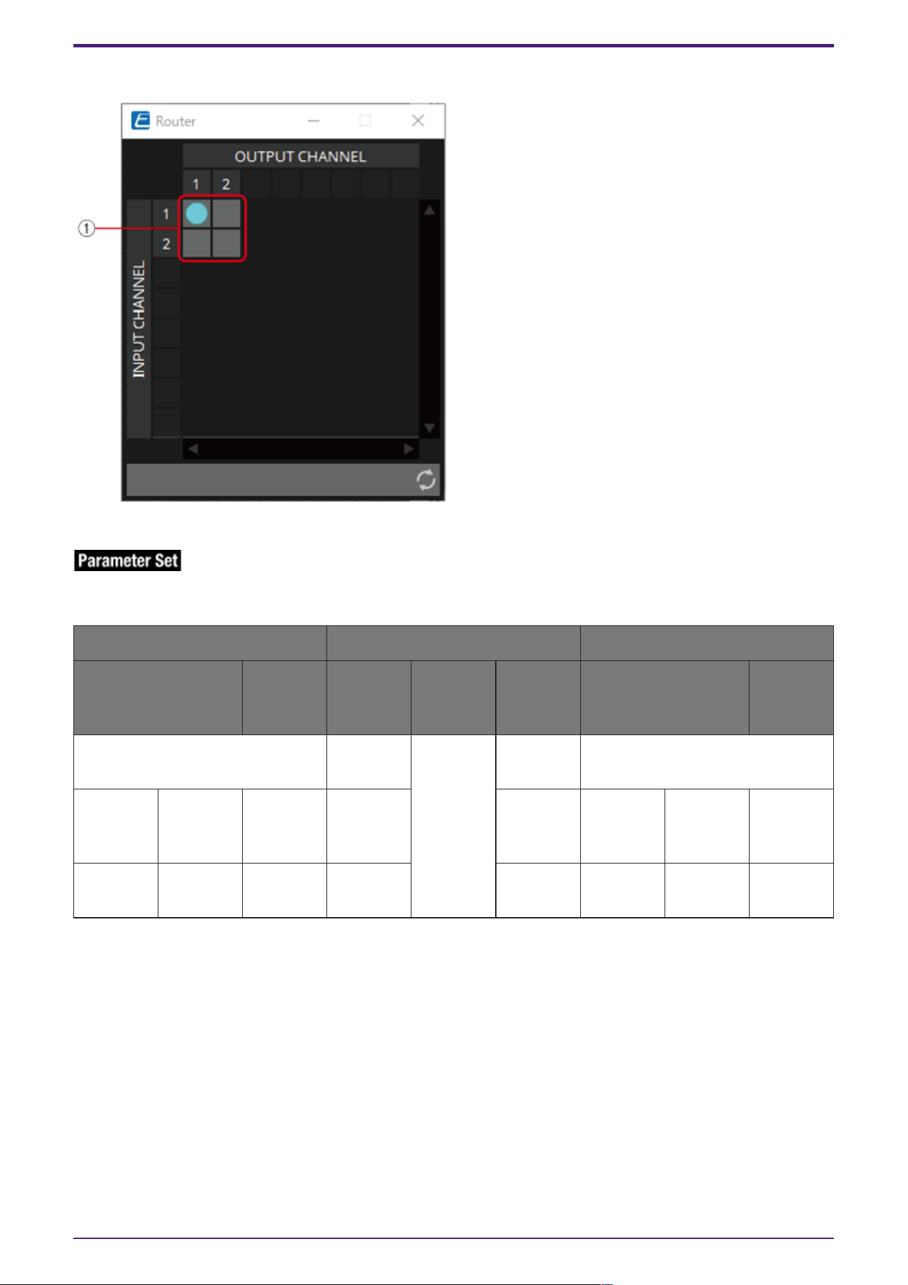
3.23.1. ”Router” component editor
① This is the router that distributes inputs signals. Clicking on a square toggles the output on or off.
Parameter types of the input/output values for each Port
Input Value Operation Output Value
Type Range Input
Port
Name
Trigger/P
rocessing
Output
Port
Name
Type Range
Through ● CH
(1,2..)
Processin
g: Router
● CH
(1,2..)
Input Valueと同じ値
Value Num
OFF:0,
ON:1
● OUT
(1,2..)
(In1,2..)
● OUT
(1,2..)
(In1,2..)
Value Num
OFF:0,
ON:1
Value Num INPUT CH
No
● OUT
(1,2..) Sel
● OUT
(1,2..) Sel
Value Num INPUT CH
No
3. Control Components
ProVisionaire Design Component Guide | 159

3.24. Controller: GPI In
Converts signals input from GPI IN into control signals that can be handled by the Control layer.
For the input from each GPI In connector (16 connectors), a continuous value (normalized from 0 to 1)
is output from each output port.
There are two GPI Input setting methods.
• Configure the settings in the GPI Input dialog that opens from the [Tools] button on the
device sheet.
Try this method to execute a single function using the input from a single [GPI IN] connector.
• Add the GPI Input component to the Control layer of the device sheet and set it using in the
Component Editor.
Try this method if you want to control multiple parameters/functions simultaneously by input
from a single [GPI IN] connector, or if you want to combine control components to create
complex operations.
* GPI Input is configured simultaneously by dialog setting and by the GPI Input component of the
Control layer.
3. Control Components
160 | ProVisionaire Design Component Guide
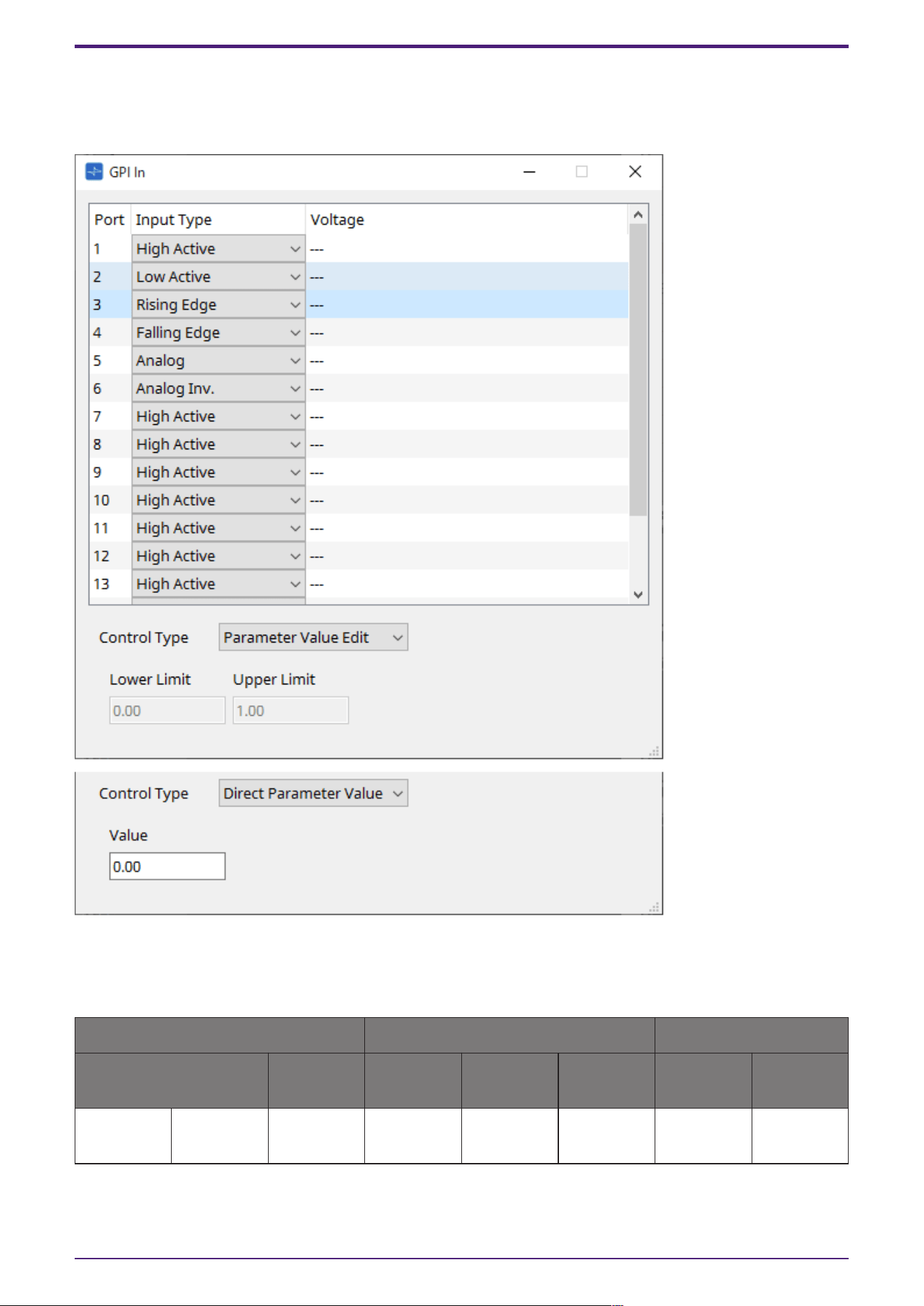
3.24.1. ”GPI Input” component editor
The input GPI signal is converted to a normalized value (0 to 1) using the specified method, and is then
output.
Refer to the GPI Input dialog in the ProVisionaire Design User Guide for the rest.
Parameter types of the input/output values for each Port
Input Value Operation Output Value
Type Range Input Port
Name
Trigger/Pr
ocessing
Output
Port Name
Type Range
- - - - Trigger:
GPI IN
● CH
(1,2..)
Normalized 0.00–1.00
3. Control Components
ProVisionaire Design Component Guide | 161

3.25. Controller: GPI Out
Outputs the GPI Out signal from the GPI Out connector.
There are two GPI Output setting methods.
• Configure the settings in the GPI Output dialog that opens from the [Tools] button on the
device sheet.
Try this method if you are using one operation as a trigger and outputting from a single [GPI
OUT] connector.
• Add the GPI Output component to the Control layer of the device sheet and set it using in
the Component Editor.
Try this method if you want to use multiple operations as a trigger and want to output them
from a single [GPI OUT] connector, or if you want to combine control components to create
complex operations.
* The output port type settings are linked in the dialog and the GPI Output component of the Control
layer.
3. Control Components
162 | ProVisionaire Design Component Guide
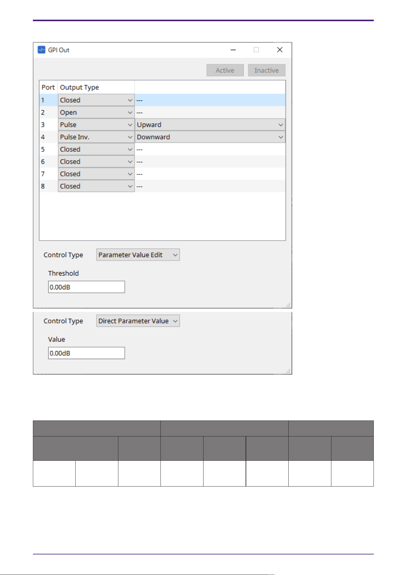
3.25.1. ”GPI Output” component editor
Refer to the GPI Input dialog in the ProVisionaire Design User Guide for the rest.
Parameter types of the input/output values for each Port
Input Value Operation Output Value
Type Range Input Port
Name
Trigger/Pr
ocessing
Output
Port Name
Type Range
Value Num
OFF:0,
ON:1
● CH
(1,2..)
Trigger:
GPI OUT
- - -
3. Control Components
ProVisionaire Design Component Guide | 163
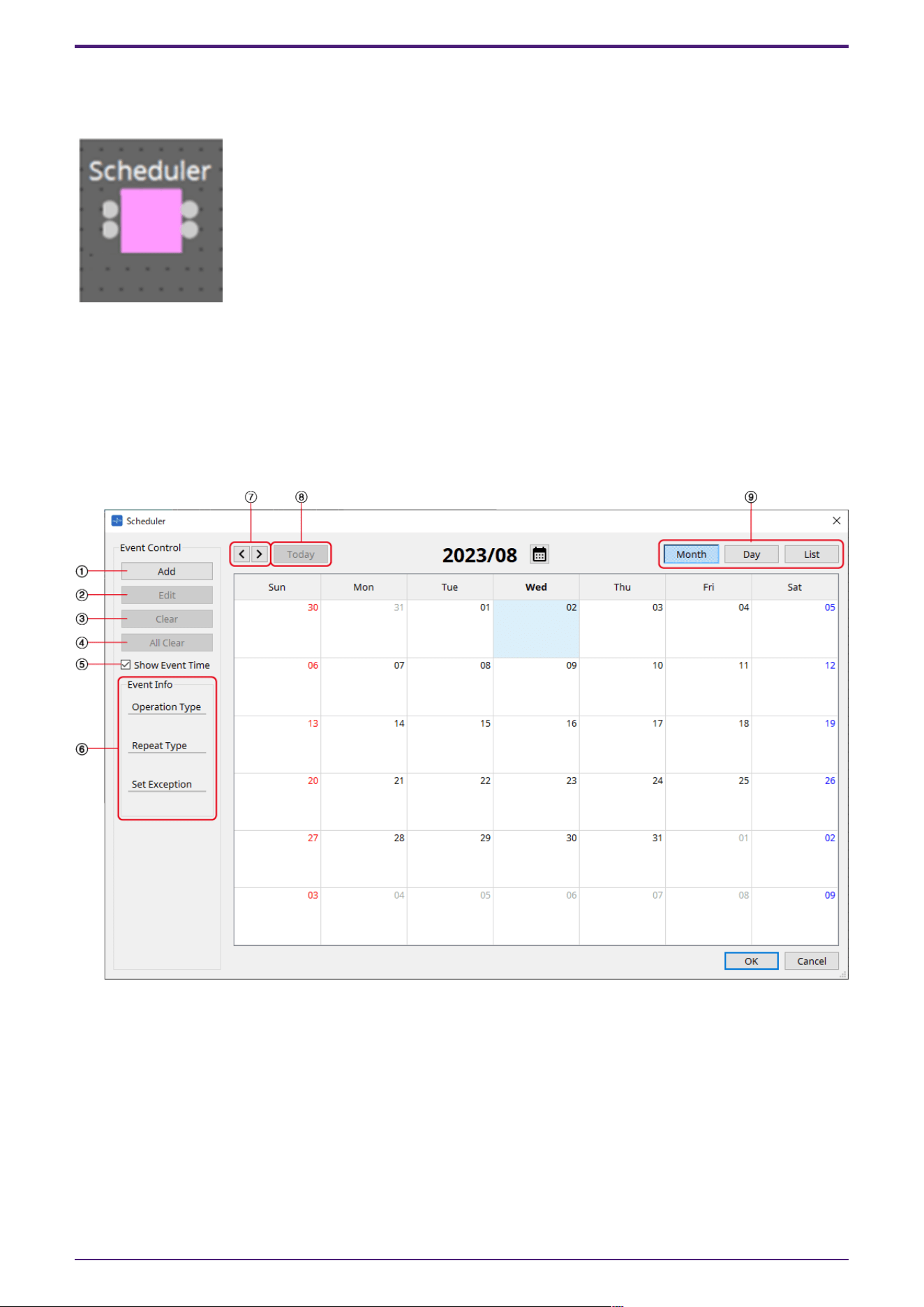
3.26. Controller: Scheduler
Outputs a trigger at the time the event is activated.
INPUT
Enable 001: Controls the event’s ”Enable” parameter (OFF:0, ON:1).
OUTPUT
Event 001: Outputs 1 at the time the event activates
3.26.1. “Scheduler” component editor
① [Add] button
Opens the “Add Event” dialog.
② [Edit] button
Opens the selected event’s edit dialog. See the Add Event dialog for a description of the setting items.
③ [Clear] button
Deletes the settings for the currently-selected event.
④ [All Clear] button
Deletes all events.
3. Control Components
164 | ProVisionaire Design Component Guide
⑤ [Show Event Tim] check box
When this check box is empty (off), the event occurrence time is not displayed. This is to save display
space.
⑥ Event Info
Displays a summary of the currently selected event.
⑦ [<][>] buttons
For Month, this advances/returns the display by one month.
For Day, this advances/returns the display by one day.
⑧ [Today] button
In Month view, this jumps to the month that includes today.
For the Day view, this display today’s schedule.
⑨ [Month]/[Day]/[List] selection button
Switches the calendar to month view/day view or event list view.
•
Month/Day
In the calendar, double-click the date you want; the “Add Event” dialog box will appear.
Events other than periodic events can be moved by dragging and dropping.
•
List
Displays events linked to output terminals in numerical order of the terminal numbers.
Events can be enabled or disabled using the Enable checkbox. Additionally, this parameter can be
assigned to each function.
Parameter types of the input/output values for each Port
Input Value Operation Output Value
Type Range Input Port
Name
Trigger/Pr
ocessing
Output
Port Name
Type Range
Value Num
OFF:0,
ON:1
● Enable
(001–100)
- - - -
- - - - - ● Event
(001,
002…)
- 1
3. Control Components
ProVisionaire Design Component Guide | 165
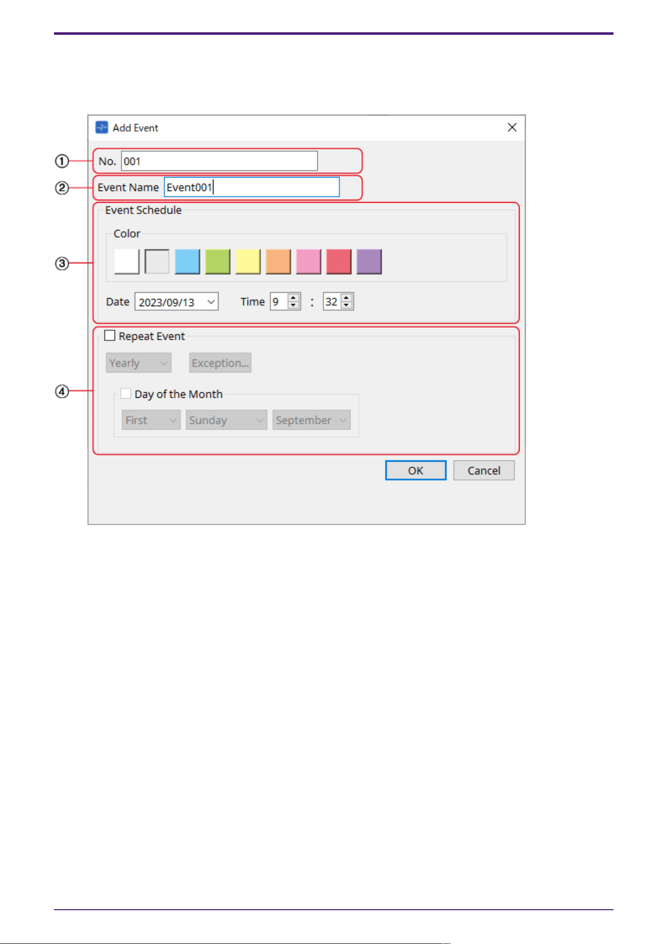
3.26.2. “Add Event” dialog box
You can add an event here.
One-time events or recurring events can be configured.
① [No.] text box
Specifies the output terminal of the component issuing the event.
This can be changed after setting.
② [Event Name] text box
Shows or edits the event name.
③ Event Schedule
•
[Color] selection button
Selects the color for events displayed on the calendar. Using this to color-code events makes
them easier to see and differentiate.
•
[Date] list box
Sets the event occurrence date. (YY/MM/DD)
Change the date by entering it directly or by clicking on the V icon to the right to change the
date in the calendar that is displayed.
Depending on the Repeat Event setting, this may not be displayed.
•
[Time] box
Sets the event start time. (Hour:Minutes, uses 24 hour format)
Click on the hour/minute you wish to set and change the value using the spin box or by typing
directly.
3. Control Components
166 | ProVisionaire Design Component Guide
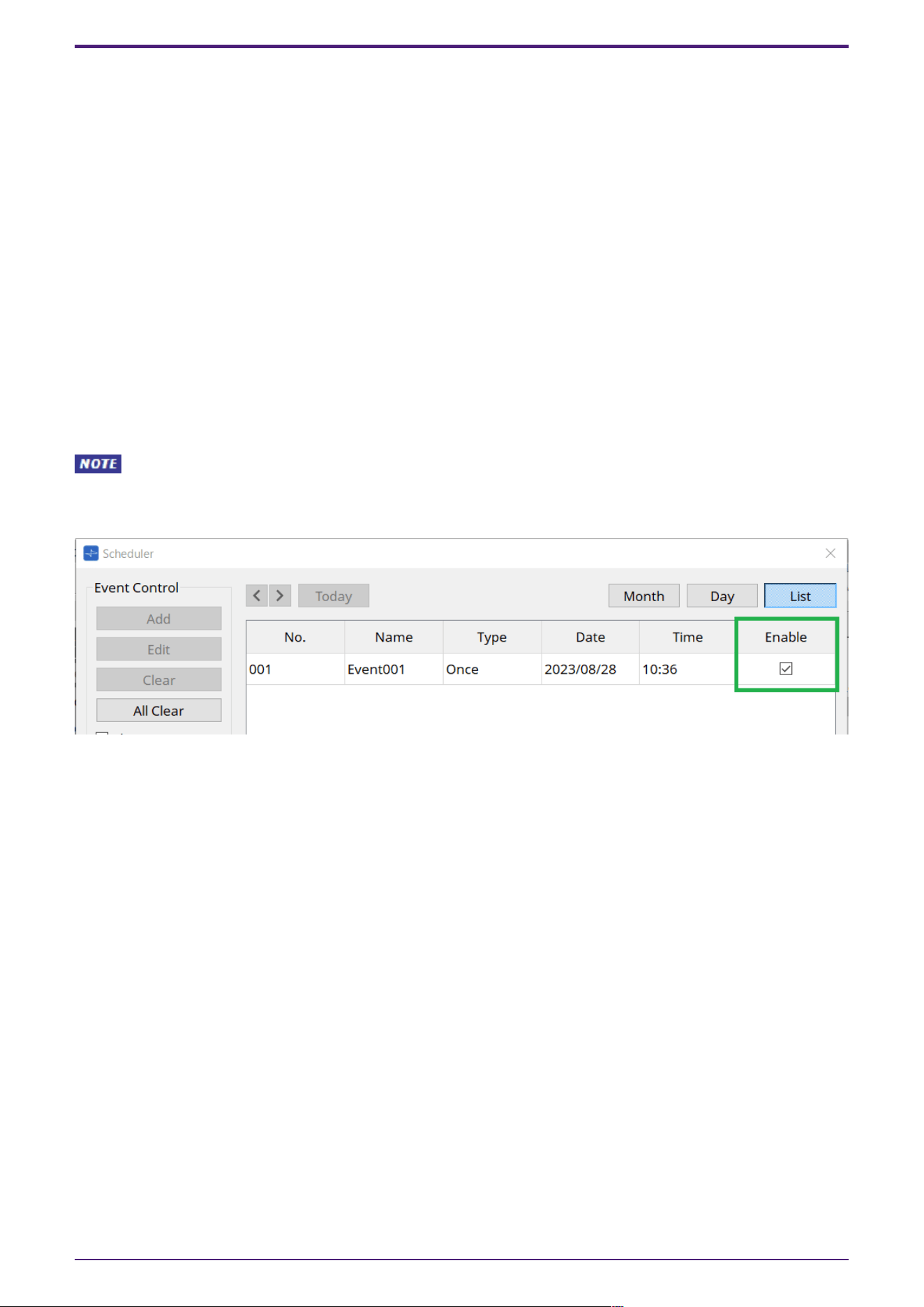
If Repeat Event below is checked and the event interval is set to "Hourly", only minutes can be
set.
To manage time under 1 minute, connect a Delay control component to the component’s output
terminal and adjust the time there.
④ Repeat Event
•
[Repeat Event] check box
By selecting this check box you can specify a repeating event.
•
[Yearly]/[Monthly]/[Weekly]/[Daily]/[Hourly] combo box
Checking the Day of the Month checkbox in Yearly will disable the Date in the "Event Schedule"
and repeat the event with the specified settings.
Checking the Day of the Week checkbox in Monthly will disable the Date in the "Event Schedule"
and repeat the event with the specified settings.
•
[Exception] button
For repeating events, this sets the date and time when the event will not be activated as an
exception.
The enable/disable for each event can be configured in the "Enable" setting on the List screen.
When this is unchecked (empty), no trigger will be issued.
Enable parameters can be assigned to controllers such as DCP, GPI, etc. by using drag-and-drop.
For details on settings and configuration, refer to the Audio Processor MTX5-D/MTX-3 "Scheduler
dialog" in the user guide.
3. Control Components
ProVisionaire Design Component Guide | 167
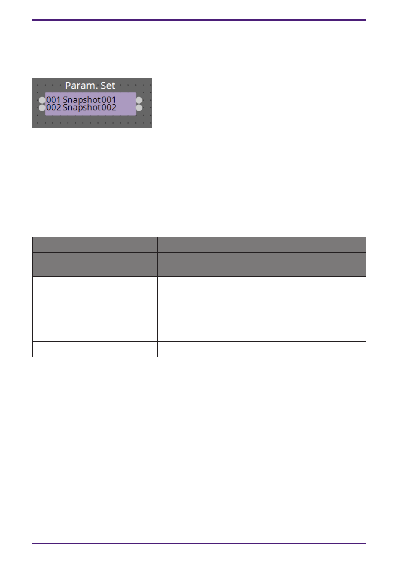
3.27. Parameter Set
Recalls a snapshot when there is an input on the input port.
For information on how to add components to the control layer, refer to "Controlling a Snapshot and
ParamSet in the control component" in the user guide.
(For 2 inputs)
INPUT
Snapshot 001 : The input value to recall a snapshot (any number)
Snapshot 002 : The input value to recall a snapshot (any number)
OUTPUT
Snapshot 001 : Outputs 1 when a snapshot is recalled
Snapshot 002 : Outputs 1 when a snapshot is recalled
Parameter types of the input/output values for each Port
Input Value Operation Output Value
Type Range Input Port
Name
Trigger/Pr
ocessing
Output
Port Name
Type Range
Value Num Any value ●
Snapshot(0
01–100)
- - - -
- - - - - ●
Snapshot(0
01–100)
- 1
Value Num 0–100 Sel - - - -
3. Control Components
168 | ProVisionaire Design Component Guide
3.28. Snapshot
Recalls a snapshot triggered by an input.
Refer to "Controlling a Snapshot and ParamSet in the control component" in the user guide for
information on adding components to the control layer.
INPUT
Snapshot 001 : The input value to recall a snapshot (any number)
OUTPUT
Snapshot 001 : Outputs 1 when a snapshot is recalled
Parameter types of the input/output values for each Port
Input Value Operation Output Value
Type Range Input Port
Name
Trigger/Pr
ocessing
Output
Port Name
Type Range
Value Num Any value ●
Snapshot(0
01–100)
- - - -
- - - - - ●
Snapshot(0
01–100)
- 1
Yamaha Pro Audio global website
https://www.yamahaproaudio.com/
Yamaha Downloads
https://download.yamaha.com/
3. Control Components
ProVisionaire Design Component Guide | 169

© 2023 Yamaha Corporation
Published 05/2025
YJ-C0