
-- Page
1
--
INDEX
Trademarks .....................................................................................................................2
Safety Information ...........................................................................................................2
Safety Instructions ...........................................................................................................3
Safety Warning ............................................................................................................... 3
Chapter 1 General Introduction .................................................................................. 5
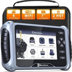
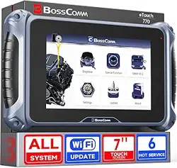
1.1 Layout for eTouch 770 Series diagnostic scanner ................................................. 5
1.2 Technical Specifications .........................................................................................5
1.3 Standard Accessory Kits ........................................................................................ 6
Chapter 2 Get Ready before Diagnosis ......................................................................6
2.1 Cable Connection for On-Board Diagnosis ............................................................ 6
2.2 Application Icon Introduction .................................................................................. 7
Chapter 3 To Start a New Test ...................................................................................9
3.1 Application Icon Introduction .................................................................................. 9
3.2 Vehicle Selection .................................................................................................. 10
3.3 Special Function ................................................................................................... 16
Chapter 4 Software Update ...................................................................................... 23
4.1 Update via WIFI..................................................................................................... 23
4.2 Update via USB..................................................................................................... 24
Chapter 5 Troubleshooting ....................................................................................... 25
Service Procedures .......................................................................................................26
Warranty ....................................................................................................................... 27
Copyright .......................................................................................................................28
Disclaimer ..................................................................................................................... 28

-- Page
2
--
Trademarks
BOSSCOMM is the trademark of BOSSCOMM TECH CORP, registered
worldwide. All other marks are trademarks or registered trademarks of
their respective holders.
No parts of this manual may be reproduced, stored in a retrieval system or
transmitted, in any form or by any means, electronic, mechanical,
photocopying, recording, or otherwise without the prior written permission
of BOSSCOMM TECH CORP.
Disclaimer of Warranties and Limitation of Liabilities
All information, specifications and illustrations in this manual are based
on the latest information available at the time of printing. BOSSCOMM
reserves the right to make changes at any time without notice. While
information of this manual has been carefully checked for accuracy, no
guarantee is given for the completeness and correctness of the contents,
including but not limited to the product specifications, functions, and
illustrations.
BOSSCOMM will not be liable for any direct damages or for any special,
incidental, or indirect damages or for any economic consequential
damages (including lost profits).
Safety Information
For your own safety and the safety of others, and to prevent damage to
the device and vehicles upon which it is used, it is important that the
safety instructions herein presented throughout this manual be read and
understood by all persons operating or coming into contact with the
device.
There are various procedures, techniques, tools, and parts for servicing
vehicles, as well as in the skill of the person doing the work. Because of
the vast number of test applications and variations in the products that
can be tested with this equipment, we cannot possibly anticipate or
provide advice or safety messages to cover every circumstance.
It is the automotive technician’s responsibility to be knowledgeable of the
system being tested. It is crucial to use proper service methods and test
procedures. It is essential to perform tests in an appropriate and
acceptable manner that does not endanger your safety, the safety of
others in the work area, the device being used, or the vehicle being
tested.

-- Page
3
--
Before using the device, always refer to and follow the safety messages
and applicable test procedures provided by the manufacturer of the
vehicle or equipment being tested. Use the device only as described in
this manual. Read, understand, and follow all safety messages and
instructions in this manual.
Safety Instructions
The safety messages herein cover situations BOSSCOMM is aware of.
BOSSCOMM cannot know, evaluate or advise you as to all of the
possible hazards. You must be certain that any condition or service
procedure encountered does not jeopardize your personal safety.
Danger: When an engine is operating, keep the service area WELL
VENTILATED or attach a building exhaust removal system to the engine
exhaust system. Engines produce carbon monoxide, an odorless,
poisonous gas that causes slower reaction time and can lead to serious
personal injury or loss of life.
Safety Warning
Always perform automotive testing in a safe environment.
Wear safety eye protection that meets ANSI standards.
Keep clothing, hair, hands, tools, test equipment, etc. away from all
moving or hot engine parts.
Operate the vehicle in a well-ventilated work area, for exhaust gases
are poisonous.
Put the transmission in PARK (for automatic transmission) or
NEUTRAL (for manual transmission) and make sure the parking
brake is engaged.
Put blocks in front of the drive wheels and never leave the vehicle
unattended while testing.
Be extra cautious when working around the ignition coil, distributor
cap, ignition wires and spark plugs. These components create
hazardous voltages when the engine is running.
Keep a fire extinguisher suitable for gasoline, chemical, and electrical
fires nearby.
Do not connect or disconnect any test equipment while the ignition is
on or the engine is running.
Keep the test equipment dry, clean, free from oil, water or grease.
Use a mild detergent on a clean cloth to clean the outside of the
equipment as necessary.

-- Page
4
--
Do not drive the vehicle and operate the test equipment at the same
time. Any distraction may cause an accident.
Refer to the service manual for the vehicle being serviced and adhere
to all diagnostic procedures and precautions. Failure to do so may
result in personal injury or damage to the test equipment.
To avoid damaging the test equipment or generating false data, make
sure the vehicle battery is fully charged and the connection to the
vehicle DLC is clean and secure.
Do not place the test equipment on the distributor of the vehicle.
Strong electro-magnetic interference can damage the equipment.
-- Page
5
--
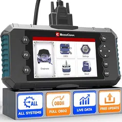
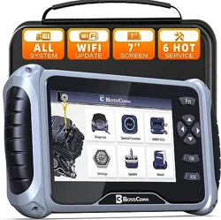
Chapter 1 General Introduction
The eTouch 770 Series easy touch diagnostic scanner is an evolutionary
smart solution for specialized automotive diagnosis combing with the best
possible coverage of OE-level diagnostics, the eTouch 770 Series
diagnostic scanner information with test instrumentation to help you
diagnose symptoms, codes, and customer complaints easily, quickly and
efficiently. This manual describes the construction and operation of these
devices and how they work together to deliver diagnostic solutions.
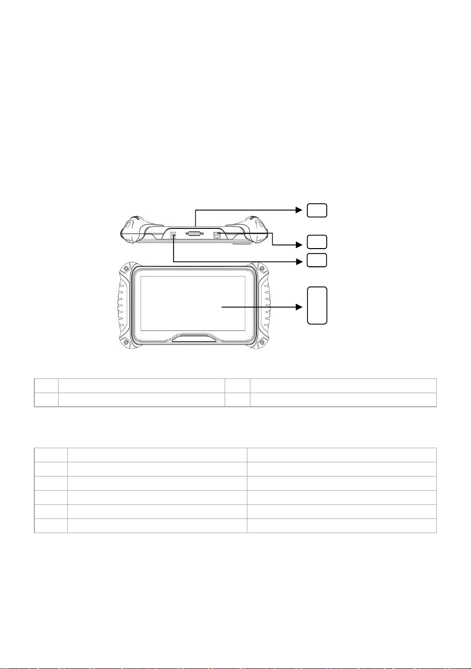
1.1 Layout for eTouch 770 Series diagnostic scanner
1
For main cable connection
2
For USB Connection
3
Power Port
4
Touch Screen Working Area
1.2 Technical Specifications
1
Screen Display
7-inch touch color screen
2
Packing Dimension (LxWxH)
306 x 195 x 87mm
3
Gross Weight for Full Kits
1kg
4
OS Platform
Linux
5
Memory
16G
6
Input Voltage
DC 12V
1
4
2
3
-- Page
6
--
1.3 Standard Accessory Kits
1
Black Carton Box
2
Main Unit
3
OBD-II main cable
4
USB Cable
5
User Manual
Chapter 2 Get Ready before Diagnosis
By establishing a data link to the electronic control systems of the vehicle
being serviced, the Diagnostics application allows you to retrieve
diagnostic information, view live data parameters, and perform active
tests. The Diagnostics application can access the electronic control
module (ECM) for various vehicle control systems, such as engine,
transmission, anti-lock brake system (ABS), airbag system (SRS) etc.
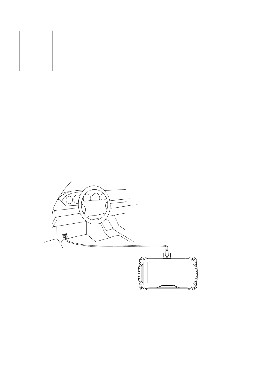
2.1 Cable Connection for On-Board Diagnosis
Make sure the eTouch 770 Series diagnostic scanner is well connected
for vehicle diagnosis.
Connection:
To connect the main unit with the OBD-II main cable to get power supply.
-- Page
7
--
The system boots up and shows the screen with the eTouch 770 Series
diagnostic scanner Job Menu as below:
Almost all operations on the display are controlled by menu driven, which
allows you to quickly locate the test procedure, or data that you need,
through a series of choices and questions. Detailed descriptions of the
menu structures are found in the chapters for the various applications.
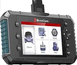
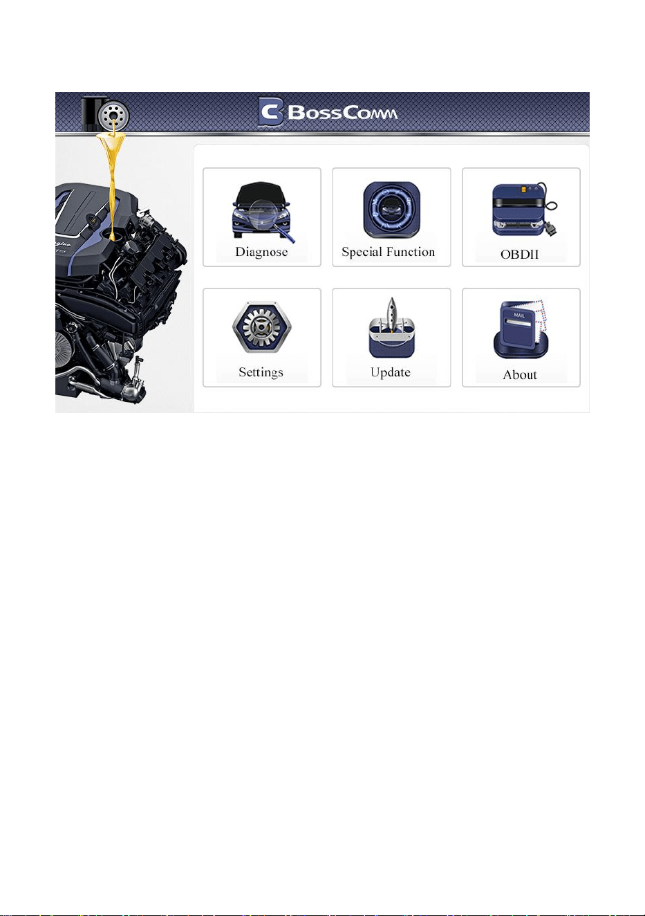
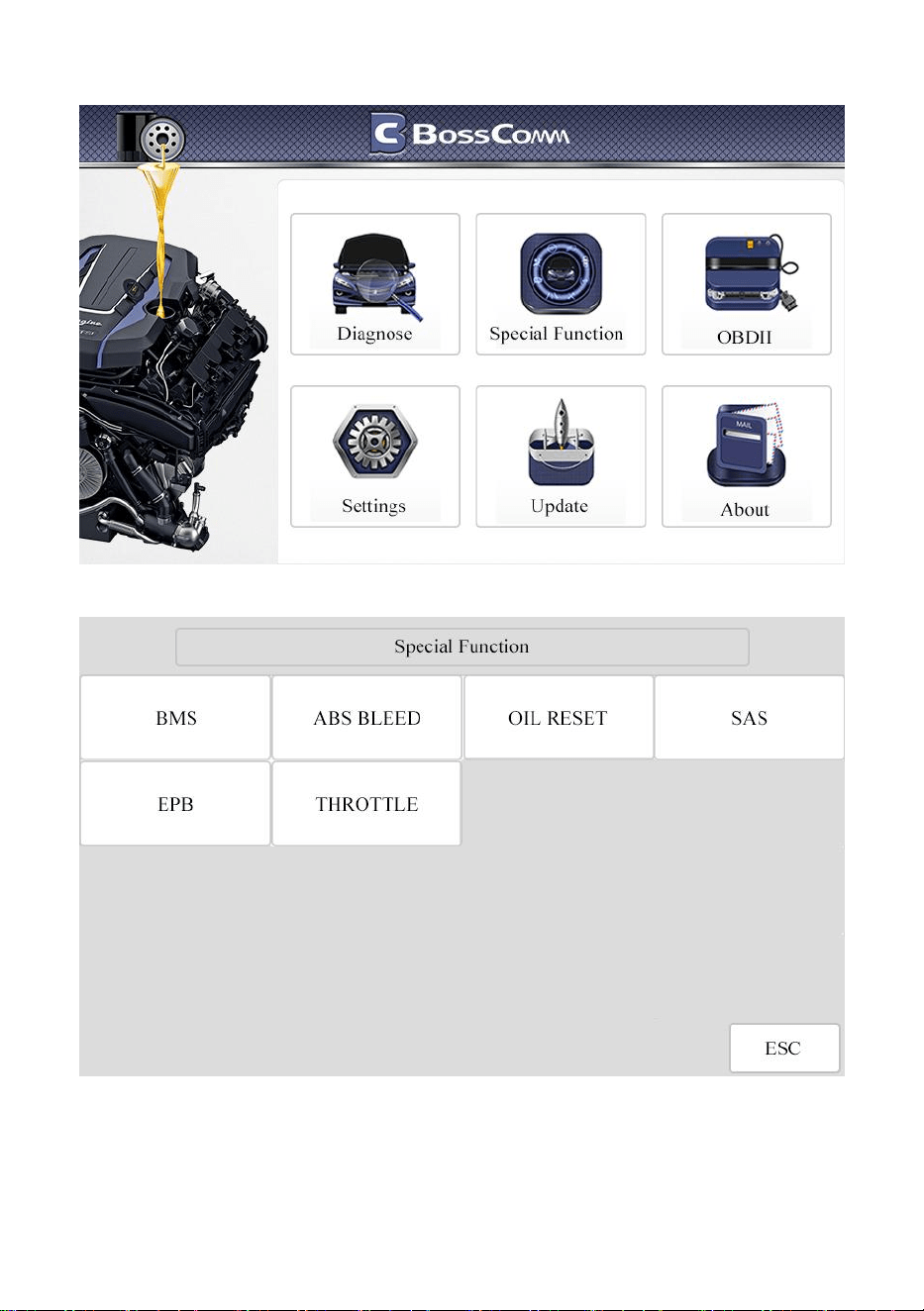
2.2 Application Icon Introduction
The Application buttons configure the eTouch 770 Series diagnostic
scanner for the type of operation or activity to be performed.
Providing 6 modules on the screen including Diagnose, Special Function,
OBDII, Settings, About and Update. Each module supports different
functions.
-- Page
8
--
NAME
PICTURES
DESCRIPTION
Diagnose
Executes the corresponding vehicle
diagnostic program based on the selected
region and vehicle make.
Special
Function
Provides quick access to vehicle systems for
the most commonly performed service
functions and maintenance operations.
Settings
Adjusts and views system settings, including
the measurement unit for the diagnostic
system, the display language for the device,
log settings.
OBDII
All modes of OBDII test for cars after1996
and newer
I/M
Including read/erase codes, view live data,
view freeze frame data, view I/M readiness,
O2 monitor test, on-board monitor test etc.
DTC
Library
To provide you with the latest definition of
PCBU fault codes. For example, after
entering "P02AE", you will get its definition
as "Cylinder 6 – Fuel Trim at Max Limit"
About
Displays the device information including
serial number, register password, firmware
version and system software version.
Update
When the device is connected to the
Internet, checks for the latest version for
vehicle diagnostic programs, and performs
updating procedures.

-- Page
9
--
Via WiFi
Update via Wi-Fi
Via USB
Update via PC client
Feedback
You can upload the vehicle diagnosis log to
faster solve your problems during vehicle
diagnosing.
Chapter 3 To Start a New Test
To start a new test, you need to establish the proper vehicle communication to
the eTouch 770 Series Diagnostic Scanner; you need to follow the screen
instructions step by step for the car testing. The operations require connecting the
eTouch 770 Series Diagnostic Scanner main unit to the test vehicle through the
OBD-II main cable.
No.
Description
Features and Functions
1
OBDII Main Cable
To connect the connector and the vehicle
2
Diagnostic Scanner
Main Unit
To communicate with vehicle and display the
diagnostic result
3
Diagnostic Socket
on car
Socket location varies based on different car
makes/models
3.1 Application Icon Introduction
Name
Description
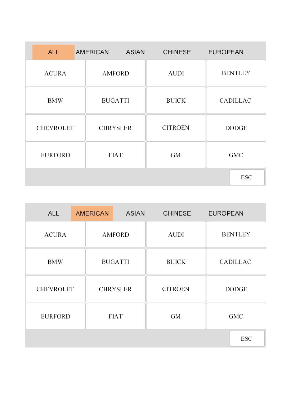
European
Displays the European vehicle menu. Including BMW, Alfa,
Jaguar, Land Rover, Fiat, Ford, Citroen, Mercedes-Benz,
Volkswagen, Audi, Volvo, Renault, etc.
Asian
Displays the Asian vehicle menu. Including Toyota, Lexus,
Honda, Acura, Nissan, Infiniti, Mitsubishi, Daewoo, Mazda,
Hyundai, Kia, Isuzu, Suzuki, etc.
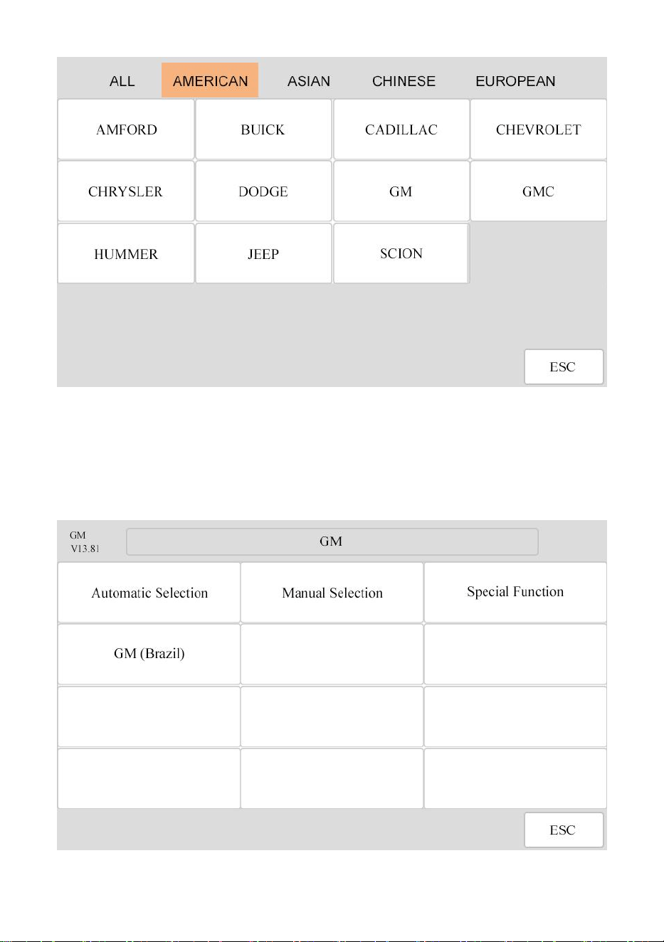
American
Displays the USA vehicle menu. Including GM, Chrysler,
Ford, etc
Chinese
Displays Chinese domestic vehicle menu. Including
Chana, Chery, Geely, GWM, MG, Roewe, etc

-- Page
10
--
Language
English, Portuguese,Hungarian, Russian, Polish, Italian,
Traditional Chinese, Dutch, Simplified Chinese, Spanish,
French, German, Turkish
Log
Two options for Logging On and Logging OFF. [Logging ON]
must be set if the client wants to record the live data,
otherwise the client cannot send logging files.
Unit
To provide two options for the unit of live data: Metric Units
and Imperial Units
LCD
To provide the display test option for the main unit.
3.2 Vehicle Selection
When the main unit is properly connected to the vehicle, click the Diagnostics
icon button on the eTouch 770 Series diagnostic scanner.
The eTouch 770 Series diagnostic scanner supports more than three methods
for Vehicle Identification with the Automatic Selection, Manual Selection, and
Special Function.
3.2.1 Automatic selection
The eTouch 770 Series diagnostic scanner features the latest VIN-based Auto
VIN Scan function to identify vehicles in just one touch, which allows the
technician to quickly detect vehicles, scan all the diagnose ECUs on every vehicle
and run diagnostics on the selected system.
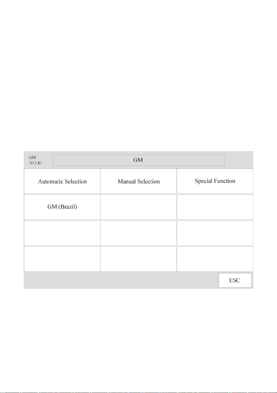
3.2.1.1 To perform Auto VIN Scan
Select [GM] from [AMERICAN]. The vehicle menu displays.
-- Page
11
--
The options come out including [Automatic Selection], [Manual
Selection] and [Special Function].
Select [Automatic Selection] and the system will proceed to acquire VIN
information automatically.
-- Page
12
--
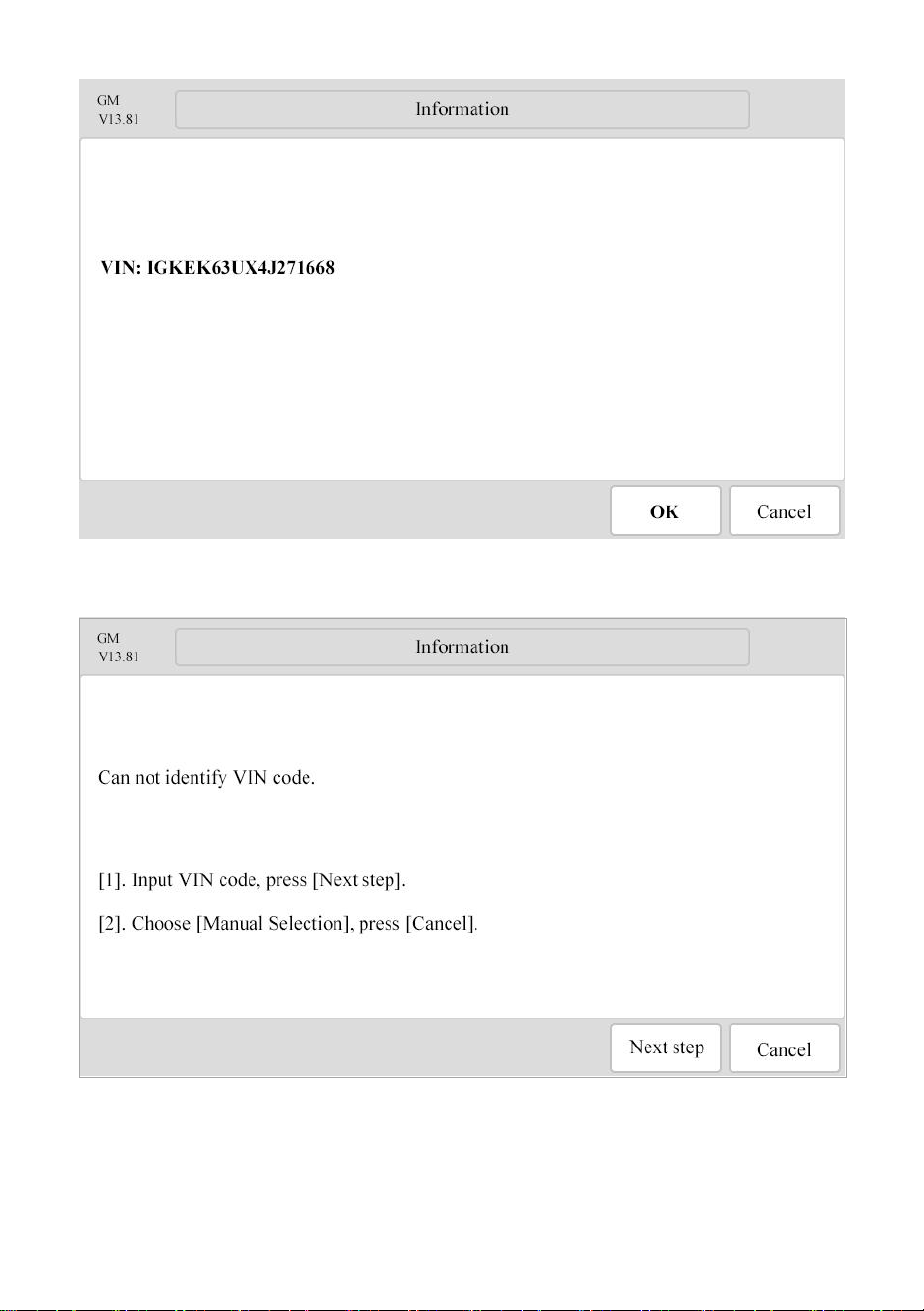
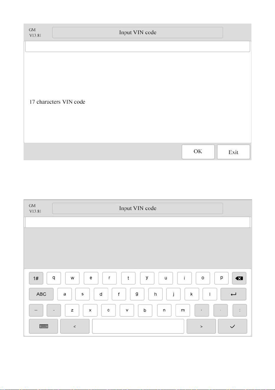
3.2.1.2 VIN code input code via virtual keyboard
In case the eTouch 770 Series diagnostic scanner provides an option for
vehicle VIN scan allowing users to input the VIN manually.
-- Page
13
--
Note:
Press the white rectangle area to show the software keyboard. Press the
rectangle area to hide the soft keyboard.
-- Page
14
--
Select the model of the vehicle accordingly. The eTouch 770 Series
diagnostic scanner displays the ECU information in details.
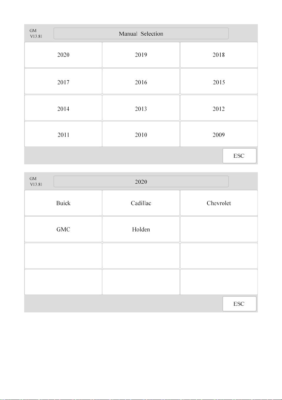
3.2.2 Manual Selection
The eTouch 770 Series Diagnostic Scanner scan also provides manual
selection (system selection) for some vehicles.
3.2.2.1 To perform Manual Selection
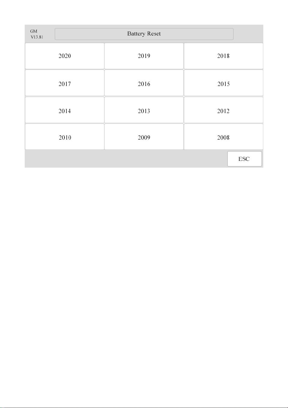
Tap the [Manual Selection] button on the screen as below.
Select the year to be tested accordingly. Take 2020 GM as an example:
The vehicle will be identified in a few seconds, and once the matching is
successful, the system will guide you the vehicle diagnostics screen
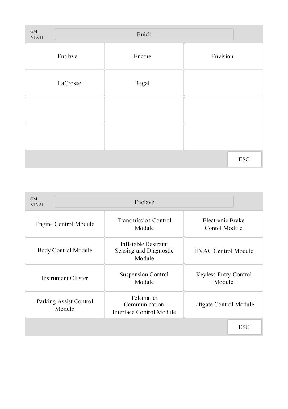
directly. Select [Buick] as below:
-- Page
15
--
Select [Enclave] as below:
-- Page
16
--
Select [Engine Control Module] from the list as below:
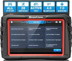
3.3 Special Function
The eTouch 770 Series Diagnostic Scanner also provides special
functions for some vehicles with quick access to different car makes.
-- Page
17
--
Click the button [Special Function] from the menu as below:
The following page will be displayed covering some special functions list:
Note:
The numbers of the special functions may vary depending on the eTouch
770 Series diagnostic scanner.
-- Page
18
--
Press the button [BMS], the screen will display the areas selection as
following:
Press the button [GM] to start a new testing for BMS reset.
-- Page
19
--
Oil Reset Service
This function allows you to perform reset for the engine oil life system,
which calculates an optimal oil life change interval depending on the
vehicle driving conditions and climate.
This function can be performed in the following cases:
1. If the service lamp is on, you must provide service for the car. After
service, you need to reset the driving mileage or driving time so that the
service lamp turns off and the system enables the new service cycle.
2. After changing engine oil or electric appliances that monitor oil life, you
need to reset the service lamp.
Electronic Parking Brake Reset
1. If the brake pad wears the brake pad sense line, the brake pad sense
line sends a signal sense line to the on-board computer to replace the
brake pad. After replacing the brake pad, you must reset the brake pad.
Otherwise, the car alarms.
2. Reset must be performed in the following cases:
a) The brake pad and brake pad wear sensor are replaced.
b) The brake pad indicator lamp is on.
c) The brake pad sensor circuit is short, which is recovered.
d) The servo motor is replaced.

-- Page
20
--
Steering Angle Calibration
To reset the steering angle, first find the relative zero point position for the
car to drive in straight line. Taking this position as reference, the ECU can
calculate the accurate angle for left and right steering.
After replacing the steering angle position sensor, replacing steering
mechanical parts (such as steering gearbox, steering column, end tie rod,
steering knuckle), performing four-wheel alignment, or recovering car body,
you must reset the steering angle.
ABS Bleeding
This function allows you to perform various bi-directional tests to check the
operating conditions of Anti-lock Braking System (ABS).
1. When the ABS contains air, the ABS bleeding function must be
performed to bleed the brake system to restore ABS brake sensitivity.
2. If the ABS computer, ABS pump, brake master cylinder, brake cylinder,
brake line, or brake fluid is replaced, the ABS bleeding function must be
performed to bleed the ABS.
Tire Pressure Monitor System Reset
This function allows you to quickly look up the tire sensor IDs from the
vehicle’s ECU, as well as to perform TPMS replacement and sensor test.
1. After the tire pressure MIL turns on and maintenance is performed, the
tire pressure resetting function must be performed to reset tire pressure
and turn off the tire pressure MIL.
2. Tire pressure resetting must be performed after maintenance is
performed in the following cases: tire pressure is too low, tire leaks, tire
pressure monitoring device is replaced or installed, tire is replaced, tire
pressure sensor is damaged, and tire is replaced for the car with tire
pressure monitoring function.
Gear Learning
The crankshaft position sensor learns crankshaft tooth machining tolerance
and saves to the computer to more accurately diagnose engine misfires.
If tooth learning is not performed for a car equipped with Delphi engine, the
MIL turns on after the engine is started. The diagnostic device detects the
DTC P1336 'tooth not learned'. In this case, you must use the diagnostic
device to perform tooth learning for the car.
After tooth learning is successful, the MIL turns off. After the engine ECU,
crankshaft position sensor, or crankshaft flywheel is replaced, or the DTC
'tooth not learned' is present, tooth learning must be performed.

-- Page
21
--
IMMO Service
An immobilizer is an anti-theft mechanism that prevents a vehicle’s engine
from starting unless the correct ignition key or other device is present.
Most new vehicles have an immobilizer as standard equipment. An
important advantage of this system is that it doesn’t require the car owner
to activate it since it operates automatically.
An immobilizer is considered as providing much more effective anti-theft
protection than an audible alarm alone. As an anti-theft device, an
immobilizer disables one of the systems needed to start a car’s engine,
usually the ignition or the fuel supply.
This is accomplished by radio frequency identification between a
transponder in the ignition key and a device called a radio frequency reader
in the steering column. When the key is placed in the ignition, the
transponder sends a signal with a unique identification code to the reader,
which relays it to a receiver in the vehicle’s computer control module.
If the code is correct, the computer allows the fuel supply and ignition
systems to operate and start the car. If the code is incorrect or absent, the
computer disables the system, and the car will be unable to start until the
correct key is placed in the ignition.
To prevent the car being used by unauthorized keys, the anti-theft key
matching function must be performed so that the immobilizer control
system on the car identifies and authorizes remote control keys to normally
use the car.
When the ignition switch key, ignition switch, combined instrument panel,
ECU, BCM, or remote control battery is replaced, anti-theft key matching
must be performed.
Injector Coding
Write injector actual code or rewrite code in the ECU to the injector code of
the corresponding cylinder so as to more accurately control or correct
cylinder injection quantity.
After the ECU or injector is replaced, injector code of each cylinder must be
confirmed or re-coded so that the cylinder can better identify injectors to
accurately control fuel injection.
Battery Maintenance System Reset
This function enables you to perform a resetting operation on the
monitoring unit of vehicle battery, in which the original low battery fault
information will be cleared and battery matching will be done.
Battery matching must be performed in the following cases:

-- Page
22
--
a) Main battery is replaced. Battery matching must be performed to clear
original low battery information and prevent the related control module from
detecting false information. If the related control module detects false
information, it will invalidate some electric auxiliary functions, such as
automatic start & stop function, sunroof without one-key trigger function,
power window without automatic function.
b) Battery monitoring sensor. Battery matching is performed to re-match
the control module and motoring sensor to detect battery power usage
more accurately, which can avoid an error message displaying on the
instrument panel.
Diesel Particulate Filter (DPF) Regeneration
DPF regeneration is used to clear PM (Particulate Matter) from the DPF
filter through continuous combustion oxidation mode (such as high
temperature heating combustion, fuel additive or catalyst reduce PM
ignition combustion) to stabilize the filter performance.
DPF regeneration may be performed in the following cases:
a) The exhaust back pressure sensor is replaced.
b) The PM trap is removed or replaced.
c) The fuel additive nozzle is removed or replaced.
d) The catalytic oxidizer is removed or replaced.
e) The DPF regeneration MIL is on and maintenance is performed.
f) The DPF regeneration control module is replaced.
Electronic Throttle Position Reset
This function enables you to make initial settings to throttle actuators and
returns the “learned” values stored on ECU to the default state.
Doing so can accurately control the actions of regulating throttle (or idle
engine) to adjust the amount of air intake.
-- Page
23
--
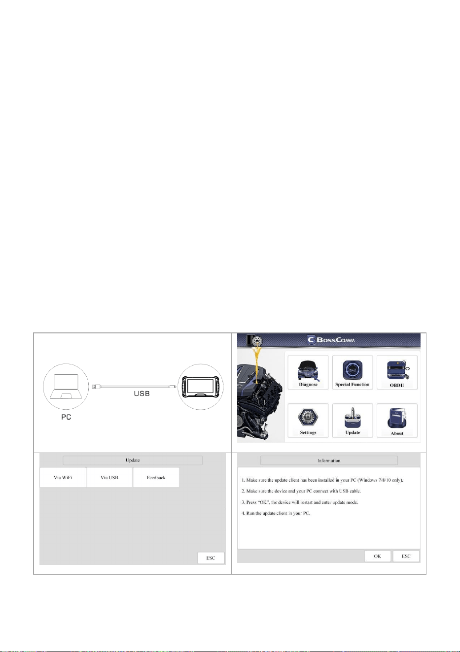
Chapter 4 Software Update
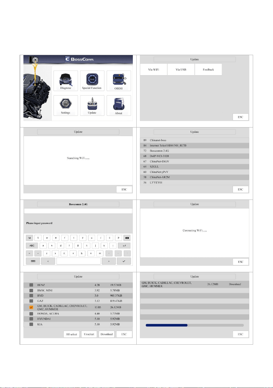
4.1 Update via WIFI
Providing two ways for update: USB mode and WIFI mode.
Select [UPDATE].
Select [Via WIFI].
Searching WIFI ……
WIFI hotpot nearby. Select the correct and join.
Show keyboard at the white area, input password.
Connecting WIFI ……
Select [GM], press [Download].
Continue the operation step by step accordingly
-- Page
24
--
How to set WIFI if the mobile is iPhone 11 or higher version?
Step 1: Settings Person Hotspot
Personal Hotspot on your iPhone can provide Internet access to other
devices signed into your iCloud account without requiring you to enter the
password.
Step 2: Allow Others to Join
Allow other users or devices not signed into iCloud to look for your shared
network when you are in Personal Hotpot settings.
Note: The device can only display Wi-Fi name consisting of English
character.
Step 3: Maximize Compatibility.
1- Choose the correct name from the Wi-Fi settings on your computer or
other device.
2- Enter the password when promoted.
4.2 Update via USB
Providing the USB update procedures for software as below.
Connect the main unit to PC with the USB cable.
Select [UPDATE].
Select [Via USB].
The system will provide some information.
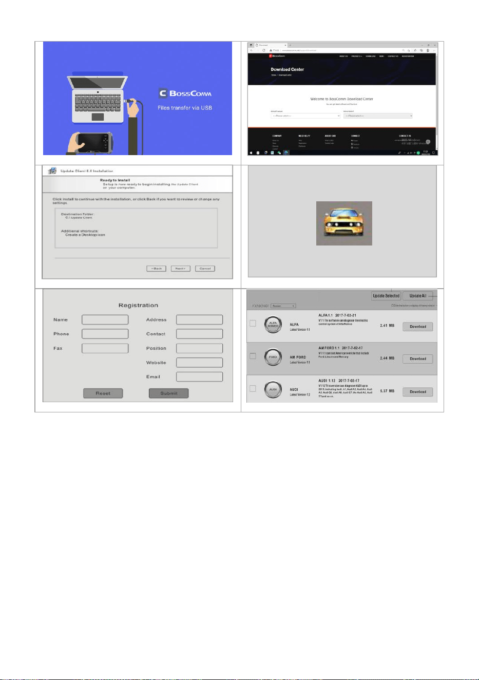
-- Page
25
--
The device will reboot and access the USB mode.
Login the website www.bosscomm.net
Install the Update Client on PC step by step.
Double click the icon of Update Client.
Input necessary details for the first registration.
Select the car makes to update the software.
Chapter 5 Troubleshooting
Why can't the PC update client automatically identify the device serial
number?
Please connect the scanner to PC before running the PC update client, and
put the scanner in the USB update mode, that is, the screen displays "Files
transfer via USB".
Why the vehicle linking error?
Follow the steps if the scanner fails to communicate with the ECU.
1– Verify the ignition is ON.
2– Check cable or connector securely connected to the vehicle DLC.
3– Turn the ignition off and wait for about 10 seconds and turn the ignition
back to ON and continue the testing.

-- Page
26
--
4– Verify the control module is not defective.
Why the device doesn’t power up?
If the auto scanner won’t power up or operate correctly in any other way,
follow the steps to check the connections:
1– Check the connector properly inserted to the socket seat.
2– Check the DLC pins bent or broken.
3– Clean the DLC pins if necessary.
Why the devices have no permission to update?
Please contact the local distributor to get authorization.
Why cannot find the WIFI name?
The device can only display the Wi-Fi name consisting of English character
or numbers.
When the display does not work properly:
Make sure the machine has been registered online.
Make sure the system software and diagnostic application software are
properly updated.
Make sure the machine is connected to the Internet.
Check all cables, connections, and indicators to see if the signal is
being received.
Service Procedures
If you have any question or problem on the operation of the product,
please contact BOSSCOMM Tech Support for help.
Website: www.bosscomm.net
Email: sales@bosscomm.net
If it becomes necessary to return your device for repair, please contact
BOSSCOMM local dealer for help.
The following information must be included:
Contact name
Return address
Telephone number
Product name
Complete description of the problem
Proof-of-purchase for warranty repairs

-- Page
27
--
Warranty
Thank you for choosing our products, we will provide you with the following
services and promises.
After the warranty period expires, repairs will be charged for replacement
parts.
After the failure, please contact the manufacturer, we will give you the most
complete service in the shortest time.
12-Month Limited Warranty
BOSSCOMM TECH CORP warrants to the original retail purchaser of this
auto scanner, that should this product or any part thereof during normal
consumer usage and conditions, be proven defective in material or
workmanship that results in product failure within twelve (12) months period
from the date of delivery, such defects will be repaired, or replaced (with
new or rebuilt parts) with Proof of Purchase, at the Company’s option,
without charge for parts or labor directly related to the defects.
The Company shall not be liable for any incidental or consequential
damages arising from the use, misuse, or mounting of the auto scanner.
Some states do not allow limitation on how long an implied warranty lasts,
so the above limitations may not apply to you.
The following items are not covered by the warranty:
1) Product subject to abnormal use or conditions, accident, mishandling,
neglect, unauthorized alternation, misuse, improper installation or
repair or improper storage;
2) Products whose mechanical serial number or electronic serial number
has been removed, altered or defected;
3) Damage from expose to excessive temperatures or extreme
environmental conditions;
4) Damage resulting from connection to, or use of any accessory or other
product not approved or authorized by Company;
5) Defects in appearance, cosmetic, decorative or structural items such as
framing and non-operative parts;
6) Product damaged from external causes such as fire, dirt, sand, battery
leakage, blown fuse, theft or improper usage of any electrical source.
All contents of the product may be deleted during the process of repair. You
should create a back-up copy of any contents of your product before
delivering the product for warranty service.

-- Page
28
--
Copyright
BOSSCOMM is a registered trademark of BC BOSSCOMM TECH CORP
(short for BOSSCOMM) in China and other countries. All other
BOSSCOMM trademarks, service marks, domain names, logos, and
company names referred to in this manual are either trademarks,
registered trademarks, service marks, domain names, logos, company
names of or are otherwise the property of BOSSCOMM or its affiliates. In
countries where any of the BOSSCOMM trademarks, service marks,
domain names, logos and company names is not registered, BOSSCOMM
claims other rights associated with unregistered trademarks, service
marks, domain names, logos, and company names. Other products or
company names referred in this manual may be trademarks of their
respective owners.
You may not use any trademark, service mark, domain name, logo, or
company name of BOSSCOMM or any third party without permission from
the owner of the applicable trademark, service mark, domain name, logo,
or company name.
Disclaimer
All information, illustrations, and specifications contained in this manual,
BOSSCOMM resumes the right of modification this manual and the
machine itself with no prior notice. The physical appearance and color may
differ from what is shown in the manual, please refer to the actual product.
Every effort has been made to make all descriptions in the book accurate,
but inevitably there are still inaccuracies, if in doubt, please contact your
local dealer of BOSSCOMM after service center, we are not responsible for
any consequences arising from misunderstanding.