IFIX-980 Intelligent Scan
www.bosscomm.net www.bosscomm.net www.bosscomm.net
First Choice For Intelligent Tablet Diagnostic Tool
WWW.MK3.COM

Index
Safety Messages ......................................................................................................................................................... 3
Safety Instructions ...................................................................................................................................................... 3
CHAPTER 1 GENERAL INTRODUCTION ....................................................................................................................... 7
1.1 LAYOUT FOR IFIX-980 MAIN UNIT............................................................................................................................ 7
1.1.1 Functional Description .................................................................................................................................. 7
1.1.2 Power Sources for IFIX-980 Main Unit .......................................................................................................... 7
1.2 LAYOUT FOR IFIX-980 VCI BOX ............................................................................................................................... 8
1.2.1 Functional Description .................................................................................................................................. 8
1.2.2 Power Sources for IFIX-980 VCI Box .............................................................................................................. 8
Gross Weight for IFIX-980NFull Kits: 5kg ................................................................................................................... 8
1.3 STANDARD PACKAGES ............................................................................................................................................. 8
CHAPTER 2 POWERING UP ................................................................................................................................... 9
CHAPTER 3 GET READY BEFORE DIAGNOSIS .............................................................................................................10
3.1 APPLICATION BUTTONS INTRODUCTION .................................................................................................................... 10
3.2 ESTABLISHING VEHICLE COMMUNICATION ................................................................................................................. 10
3.2.1 Vehicle Connection........................................................................................................................................ 11
3.2.2 VCI Connection ............................................................................................................................................. 11
3.2.2.1 Check the VCI Bluetooth Status ................................................................................................................................11
3.2.2.2 Connect VCI Bluetooth for Paring Up ........................................................................................................................12
CHAPTER 4 TO START A NEW TEST ...........................................................................................................................12
4.1 APPLICATION BUTTONS INTRODUCTION .................................................................................................................... 12
4.2 VEHICLE SELECTION .............................................................................................................................................. 13
4.2.1 Automatic selection ...................................................................................................................................... 13
4.2.1.1 To perform Auto VIN Scan ...................................................................................................................................13
4.2.1.2 VIN code input code via virtual keyboard ............................................................................................................14
4.2.2 Manual Selection ............................................................................................................................................ 15
4.2.2.1 To perform Manual Selection ...............................................................................................................................15
CHAPTER 5 DIAGNOSTIC FUNCTION DESCRIPTION ...................................................................................................17
5.1 BASIC FUNCTIONS ................................................................................................................................................ 17
5.1.1 Read Trouble Codes (DTC) ............................................................................................................................... 17
5.1.2 Clear Trouble Codes (DTC) ........................................................................................................................... 17
5.1.3 Data Display ................................................................................................................................................ 17
5.2 SPECIAL FUNCTIONS .............................................................................................................................................. 19
CHAPTER 6 SERVICE OPERATION ..............................................................................................................................20
6.1 OIL RESET SERVICE ........................................................................................................................................................ 20
6.2 ELECTRONIC PARKING BRAKE RESET .................................................................................................................................. 20
6.3 STEERING ANGLE CALIBRATION ........................................................................................................................................ 20
6.4 ABS BLEEDING ............................................................................................................................................................ 21
6.5 TIRE PRESSURE MONITOR SYSTEM RESET ........................................................................................................................... 21
6.6 GEAR LEARNING ........................................................................................................................................................... 21
6.7 IMMO SERVICE ........................................................................................................................................................... 21
6.8 INJECTOR CODING ......................................................................................................................................................... 21
6.9 BATTERY MAINTENANCE SYSTEM RESET ............................................................................................................................. 21
6.10 DIESEL PARTICULATE FILTER (DPF) REGENERATION ............................................................................................................ 22
6.11 ELECTRONIC THROTTLE POSITION RESET ........................................................................................................................... 22
CHAPTER 7 OBDII OPERATION .................................................................................................................................22
7.1 STORED CODES ............................................................................................................................................................ 22
7.2 PENDING CODES ........................................................................................................................................................... 22
7.3 FREEZE FRAME ............................................................................................................................................................. 23
7.4 ERASE CODES .............................................................................................................................................................. 23

7.5
I/M READINESS ........................................................................................................................................................... 23
7.6 LIVE DATA .................................................................................................................................................................. 23
7.7 O2 SENSOR MONITOR ................................................................................................................................................... 23
7.8 ON-BOARD MONITOR ................................................................................................................................................... 23
7.9 COMPONENT TEST ........................................................................................................................................................ 23
7.10 VEHICLE INFORMATION ................................................................................................................................................ 23
7.11 VEHICLE STATUS ......................................................................................................................................................... 23
CHAPTER 8 DATA MANAGER ....................................................................................................................................24
8.1 IMAGE VIEW ....................................................................................................................................................... 24
8.2 PDF VIEW .......................................................................................................................................................... 24
8.3 GRAPHIC VIEW .................................................................................................................................................... 25
CHAPTER 9 SETTINGS OPERATIONS ..........................................................................................................................25
9.1 LANGUAGE .......................................................................................................................................................... 25
9.2 LOGGING ............................................................................................................................................................ 26
9.3 UNIT .................................................................................................................................................................. 26
9.4 BLUETOOTH ........................................................................................................................................................ 26
CHAPTER 10 WORKSHOP MANAGEMENT ................................................................................................................27
10.1 WORKSHOP INFORMATION .................................................................................................................................... 27
10.2 CUSTOMER MANAGEMENT .................................................................................................................................... 27
CHAPTER 11 SOFTWARE UPDATE...............................................................................................................................28
11.1 UPDATE PROGRAM ............................................................................................................................................... 28
11.2 HOW TO UPDATE ............................................................................................................................................... 28
CHAPTER 12 REMOTE DESK OPERATIONS ..................................................................................................................29
CHAPTER 13 TROUBLESHOOTING ..............................................................................................................................29
CHAPTER 14 ABOUT BATTERY USAGE ........................................................................................................................29
CHAPTER 15 SERVICE PROCEDURES ...........................................................................................................................30
15.1 TECHNICAL SUPPORT ............................................................................................................................................. 30
15.2 REPAIR SERVICE ................................................................................................................................................... 30
15.3 OTHER SERVICES .................................................................................................................................................. 30
CHAPTER 16 WARRANTY ...........................................................................................................................................30
16.1 12-MONTH LIMITED WARRANTY ............................................................................................................................ 30
16.2 THIS WARRANTY DOES NOT APPLY TO:....................................................................................................................... 30
Chapter 1 General Introduction
The IFIX-980 Intelligent Scan is an evolutionary smart solution for specialized automotive diagnosis. Utilizing the
powerful A7 quad-core 1.30GHz processor, and an 8“ capacitive touch screen, combined with the best
possible
coverage of OE-level diagnostics, and based on the revolutionary multitask-capable Android Operating system,
the IFIX-980 organizes information with test instrumentation to help you diagnose symptoms, codes, and customer
complaints easily, quickly and efficiently. This manual describes the construction and operation of these devices
and how they work together to deliver diagnostic solutions.
There are two main components to the IFIX-980 system:
IFIX-980 Display Tablet – the central processor and monitor for the system
Vehicle Communication Interface (VCI) – the device for accessing vehicle data
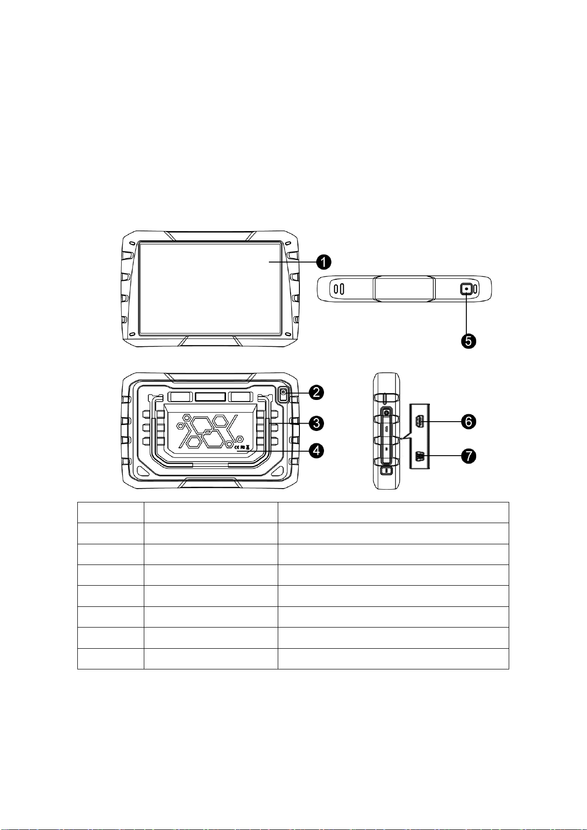
1.1 Layout for IFIX-980 Main Unit
1.1.1 Functional Description
No. Description Features and Functions
1 Touch Screen
8” IPS 1280*800
Operating System: Android 7.0
2 Camera 0.3MP + 2.0 MP
3 Built-in Battery 6800mAh Capacity lithium-polymer battery
4 Communication
Bluetooth BT 4.0
Wi-Fi 802.11 a/b/g/n/ac
5 Power Switch
ON/OFF Switch
Input: AC 100V-240V Output DC 5V , 2A
6 Storage Memory 2G + 16G
7 Mini USB Port Power Supply Port USB2.0
1.1.2 Power Sources for IFIX-980 Main Unit
The IFIX-980 Display Tablet gets power supply from Internal Battery Pack.
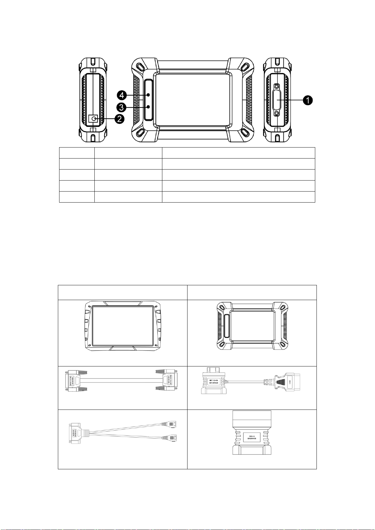
1.2 Layout for IFIX-980 VCI Box
1.2.1 Functional Description
No. Description Features and Functions
1 Connector Port To connect the main cable
2 Power Port To connect the power supply
3 Vehicle LED To display the status of the vehicle communication
4 Power LED To display the status of the power supply
1.2.2 Power Sources for IFIX-980 VCI Box
The Wireless Diagnostic Interface operates on 12-volt vehicle power, which it
receives through the vehicle
data connection port. The unit powers on whenever it is connected to an OBD II/EOBD compliant data
link connector (DLC).
Gross Weight for IFIX-980NFull Kits: 5kg
Standard Package Dimension: 46x35x14cm
1.3 Standard Packages
Description Description
IFIX-980 Main Unit VCI Communication Box
Main Cable Suitable for Mitsubishi/Hyundai-12+16
Suitable for VW/Audi-2+2 Suitable for OBD-16
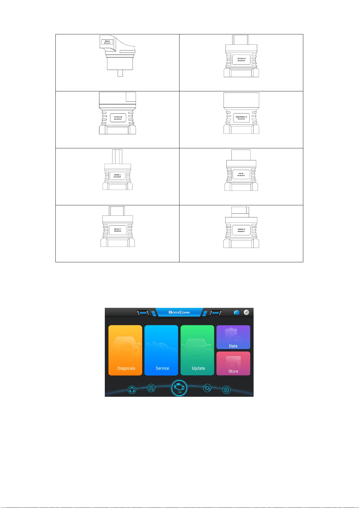
Suitable for BMW-20 Suitable for Toyota-17
Suitable for Toyota-22 Suitable for GM/Daewoo-12
Suitable for Honda-3 Suitable for Kia-20
Suitable for Mazda-17 Suitable for Nissan-14
Chapter 2 Powering Up
Make sure the IFIX-980 Display Tablet is fully charged for vehicle diagnosis.
Press the power switch on the top right side of the display tablet to switch the unit on.
The system boots up and shows the screen with the IFIX-980 Job Menu as below.
NOTE: The screen is locked by default when you first turn on the display tablet.
It is recommended to lock the screen to protect information in the system and reduce battery usage.
Almost all operations on the display tablet are controlled through the touch screen. The touch screen
navigation is menu driven, which allows you to quickly locate the test procedure, or data that you need,
through a series of
choices and questions. Detailed descriptions of the menu structures are found in the
chapters for the various applications.
Chapter 3 Get Ready before Diagnosis
By establishing a data link to the electronic control systems of the vehicle being serviced through the VCI box,
the Diagnostics application allows you to retrieve diagnostic information, view live data parameters, and
perform active tests. The Diagnostics application can access the electronic control module (ECM) for
various vehicle control systems, such as engine, transmission, antilock brake system (ABS),
airbag system
(SRS) and more.
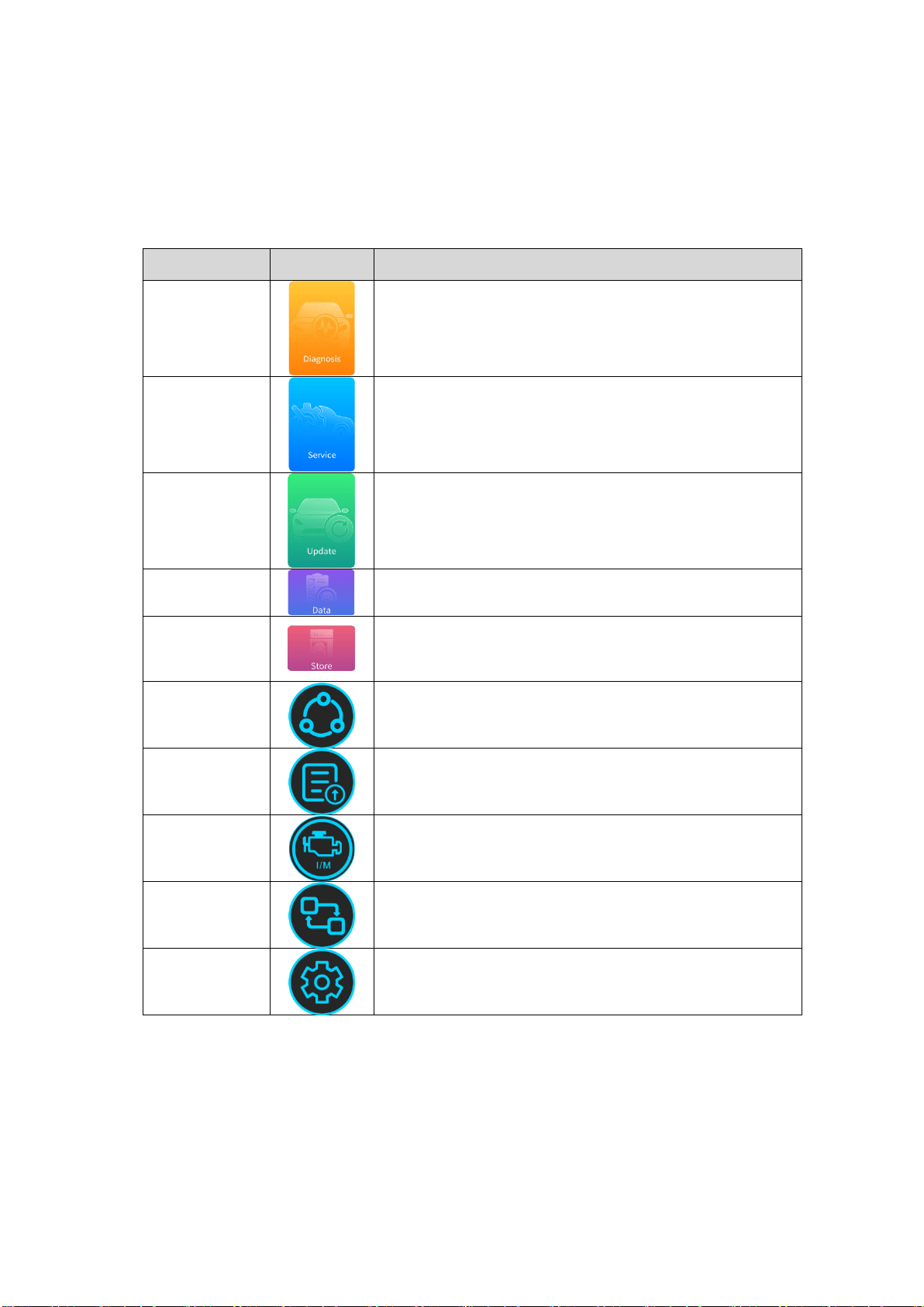
3.1 Application Buttons Introduction
The Application buttons configure the IFIX-980 for the type of operation or activity to be performed.
Name Button Description
Diagnosis
To access specific diagnosis function directly base on selection
of the areas as well as the car makes.
Service
To provide over 30+ common use service resets for the
professional workshop repairs.
Update
To access online software update for full coverage.
Internet update via Wi-Fi.
Data
To access some live data recorded or the screenshot saved
during the car diagnosis.
Store
Multitask session for an organizing and management of
operations and data from your workshop. Developed to save
data files, customer information on vehicle and related
identifiers.
Support
To provide a large database of repairs, diagnostic tips and
procedures for some professional technicians with FAQ,
Learning help and Maintenance help.
Feedback
Interactive sessions of data that allows direct contact between
technical support and the clients for quick problem solving as
well as the diagnostic errors.
OBDII
Diagnosis
10 modes of OBDII test for cars after1996 and newer including
read/erase codes, view live data, view freeze frame data, view
I/M readiness, O2 monitor test, on-board monitor test etc.
Remote
Desk
On-tool real-time remotely tech support allows rapid and
accurate solution or means of a simple data transfer between
the device and the support specialist.
Setting
To provide the diagnostic scanner system setting, including
Language setting, logging setting, unit setting and Bluetooth
setting.
3.2 Establishing Vehicle Communication
To establish proper vehicle communication to the IFIX-980 display tablet, you need to follow the steps:
The operations require connecting the IFIX-980 display tablet to the test vehicle through the VCI box using
the main cable, and test adapters (for non-OBD II vehicles).
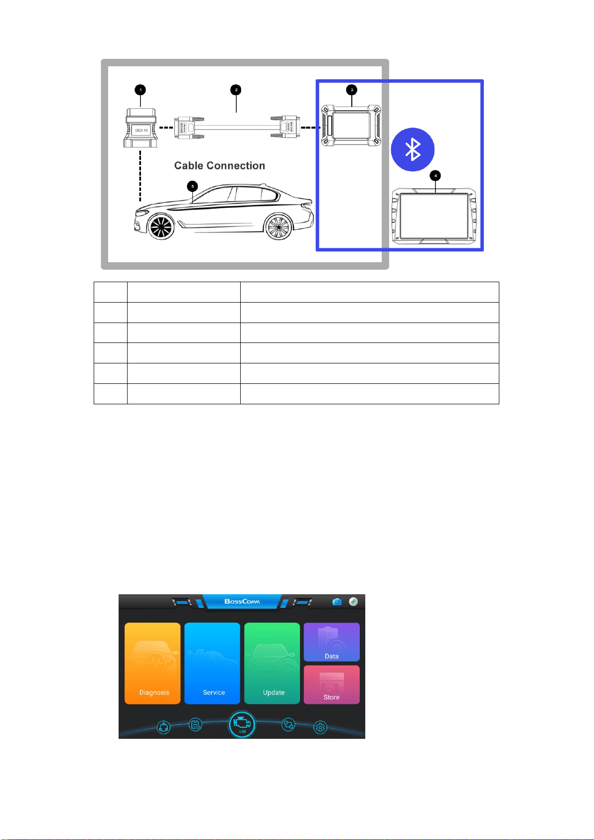
No. Description Features and Functions
1 Diagnostic Connector OBDI/OBDII Connector
2 Main Cable To connect the connector and the VCI Box
3 VCI Box Connect IFIX-980 main unit with VCI Box via Bluetooth pairing
4 IFIX-980 Main Unit To communicate with vehicle and display the diagnostic result
5 Diagnostic Socket on car Socket location varies base on different car makes/models
3.2.1 Vehicle Connection
1. Connect the main cable’s female adapter to the Vehicle Data Connector on the VCI box, and tighten the
captive screws.
2. Connect the cable’s 16-pin male adapter to the vehicle’s DLC,
which is generally located under the
vehicle dash.
Note: For details, please see the grey area in the above pictures.
3.2.2 VCI Connection
Connect the VCI box to IFIX-980 tablet via BT pairing. After the VCI box is properly connected to the vehicle,
the Power LED on the VCI box illuminates red indicating the communication of the IFIX-980 display tablet.
For details, please see the blue area in the above pictures.
3.2.2.1 Check the VCI Bluetooth Status
1. Check the status of VCI Box as below:
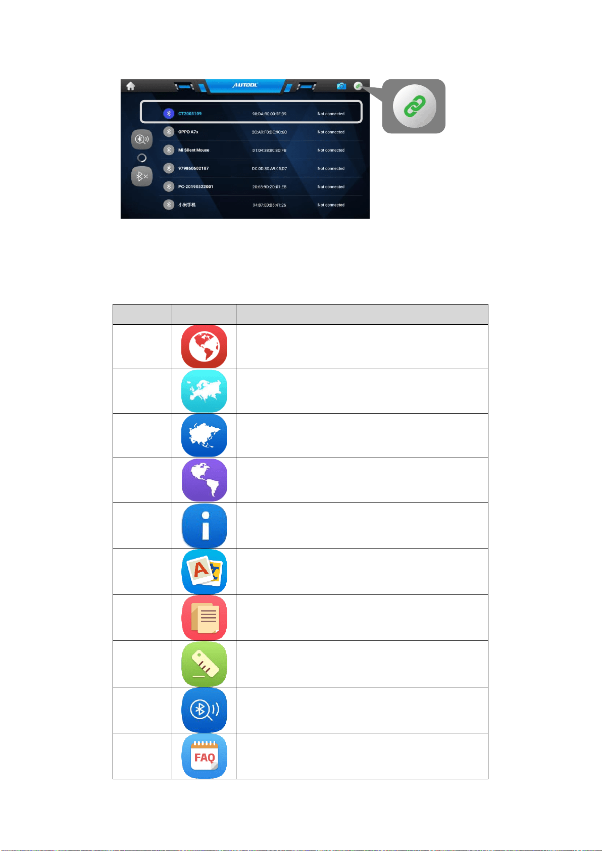
3.2.2.2 Connect VCI Bluetooth for Paring Up
2. Click the top right VCI button if it is red flashing, the following screen will be displayed:
Chapter 4 To Start a New Test
Prior to first use of the Diagnostics application, the VCI box must be synchronized with the IFIX-980 Display
Tablet to establish a communication link and make sure the VCI icon on the top right must be green.
4.1 Application Buttons Introduction
Name
Button
Description
All
Displays all the vehicle makes in the vehicle menu.
Europe
Displays the European vehicle menu.
Including BMW, Alfa, Jaguar, Land Rover, Fiat, Ford,
Citroen, Mercedes-Benz, Volkswagen, Audi, Volvo,
Renault, etc.
Asia
Displays the Asian vehicle menu.
Including Toyota, Lexus, Honda, Acura, Nissan, Infiniti,
Mitsubishi, Daewoo, Mazda, Hyundai, Kia, Isuzu,
Suzuki, etc.
USA
Displays the USA vehicle menu.
Including GM, Chrysler, Ford
About
To display the diagnostic tool information including the
software version, model hardware version, and the serial
number etc.
Multi-
language
Over 17 languages available such as English, Russian,
Korean, Hungarian, Polish, Portuguese, Japanese, Dutch,
German, Italian, French, Spanish, Arabic, Turkish etc
Logging
Two options for Logging On and Logging OFF with the slide
button. [Logging ON] must be set if the client wants to
record the live data, otherwise the client cannot send
logging files.
Unit
To provide two options for the unit of live data: Metric Unit
and English Unit.
Bluetooth
BT4.0 Enhanced wireless connectivity between the
diagnostic tool and Vehicle Communication Interface (VCI)
allowing mobility and flexibility to complete the repairs
quickly and easily
FAQ
The FAQ section provides comprehensive references for
questions frequently asked and answered about the use of
diagnostic scan tool, update procedures etc.
Workshop
Information
To edit the information of the workshop in details. Press
SAVE after editing.
Customer
Management
To edit the information of the customers including add more
clients or add more cars.
Screen
Capture
Opens the camera with short press; takes and saves
screenshot image with long press. The saved files are
auto-
stored in the Data Manager application for later
reviews.
Bluetooth
Connected
VCI green: the Bluetooth connected
VCI red: the Bluetooth disconnected
4.2 Vehicle Selection
When the VCI box is properly connected to the vehicle, and paired to the IFIX-980 main unit, the platform is
ready to start vehicle diagnosis. Click the Diagnostics application button on the IFIX-980 Job Menu, the
screen then opens the Vehicle Menu. The IFIX-980 intelligent scan supports more than three methods for
Vehicle Identification with the Automatic Selection, Manual Selection, and Service Function.
4.2.1 Automatic selection
The IFIX-980 intelligent scan features the latest VIN-based Auto VIN Scan function to identify CAN vehicles in
just one touch, which allows the technician to quickly detect vehicles, scan all the diagnosable ECUs on every
vehicle and run diagnostics on the selected system.
4.2.1.1 To perform Auto VIN Scan
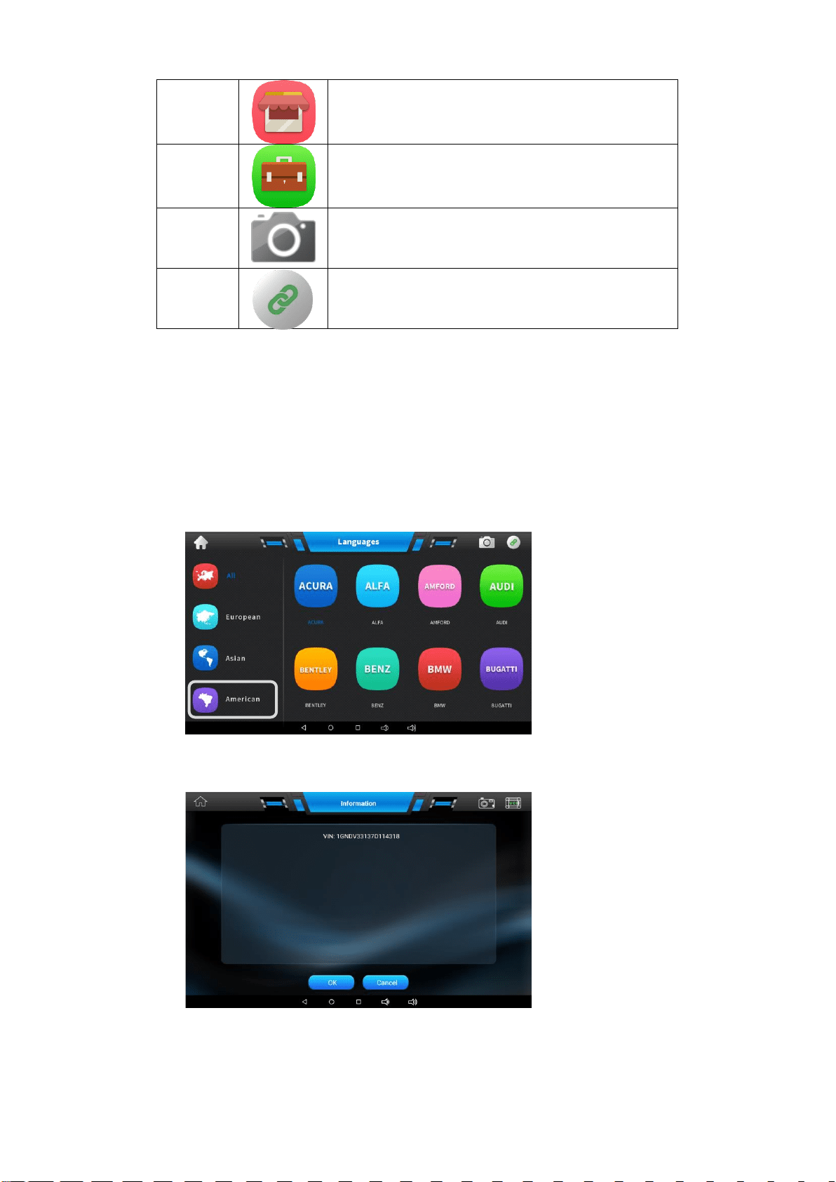
1. Select [GM] from [AMERICAN] or input [GM] in the searching area. The vehicle menu displays.
2. Two options come out including [Automatic Selection] and [Manual Selection]:
3. Select [Automatic Selection] and the system will proceed to acquire VIN information automatically.
4.2.1.2 VIN code input code via virtual keyboard
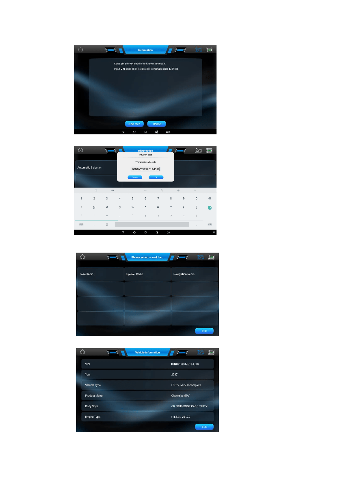
4. For some NON-CAN vehicles, the system cannot perform the Auto VIN scan.
5. In case the IFIX-980 provides an option for vehicle VIN scan allowing users to input the VIN manually.
Note: Press the green button Check Mark above to hide the virtual keyboard
6. Once the test is successfully identified, the system guide you to the vehicle diagnostics directly
7. Select the model of the vehicle accordingly. The IFIX-980 scanner display ECU information in details:
4.2.2 Manual Selection
The IFIX-980 intelligent scan also provides manual selection (system selection) for some vehicles.
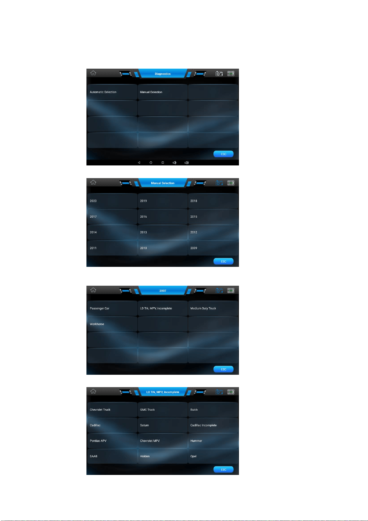
4.2.2.1 To perform Manual Selection
1. Tap the [Manual Selection] button on the screen as below.
2. Select the year to be tested accordingly. Take 2007 GM as an example:
3. The vehicle will be identified in a few seconds, and once the matching is successful, the system
will guide you the vehicle diagnostics screen directly. Select [LD Trk, MPV, Incomplete]as below:
4. Select [Chevrolet MPV] as below:
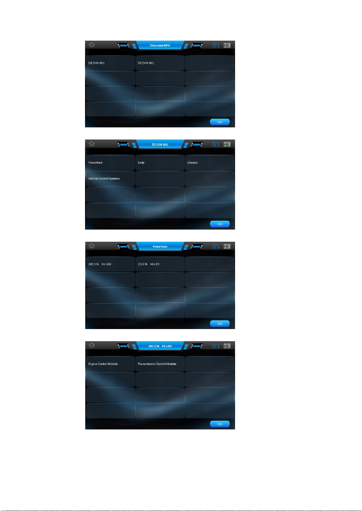
5. Select [V](VIN 5th) as below:
6. Select the testing system required from the list below. Take [Powertrain] as example as below:
7. Select [(W)3.9L V6LGD] from the list as below:
8. Select [Engine Control Module] from the list as below:
Note: Follow the screen instruction step by step to continue the diagnostic procedures.
Chapter 5 Diagnostic Function Description
5.1 Basic Functions
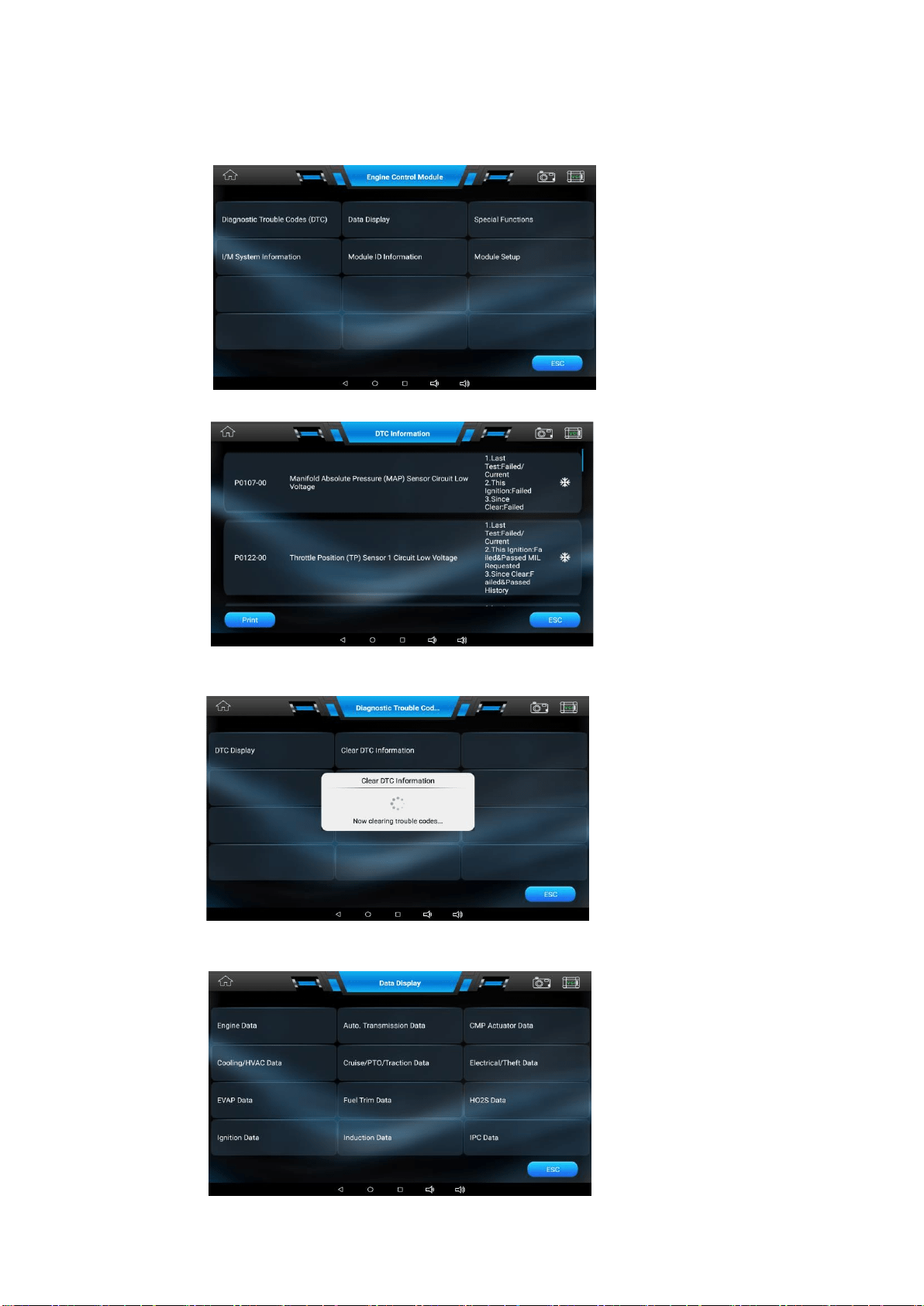
5.1.1 Read Trouble Codes (DTC)
1. Tap [GM] from the menu, tap [Diagnostic Trouble Codes (DTC)], the display is as below:
2. Tap [DTC Display] again, the screen will display as below:
5.1.2 Clear Trouble Codes (DTC)
3. Tap [Clear DTC Information] from the menu, the screen will display as below:
5.1.3 Data Display
4. Tap [Data Display], the screen will display as below:
5. Tap [Engine Data], the screen will display as below:
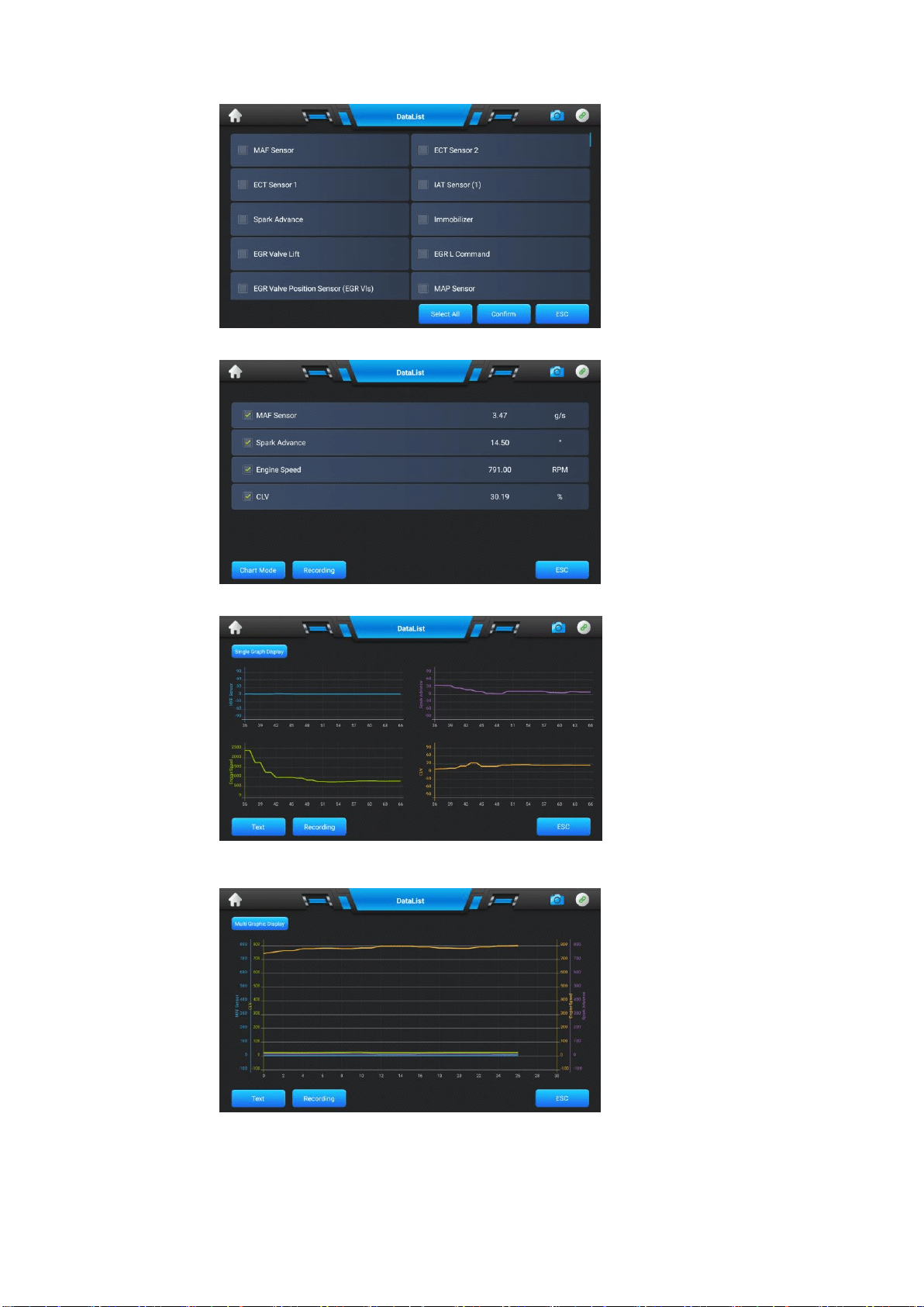
6. Select the check box in front of the item as below:
7. Press the button [Multi Graphic] on the screen in order to show curve as [Single Graphic]:
8. Note: Click [Single Graphic] again to return to the mode of [Multi Graphic].
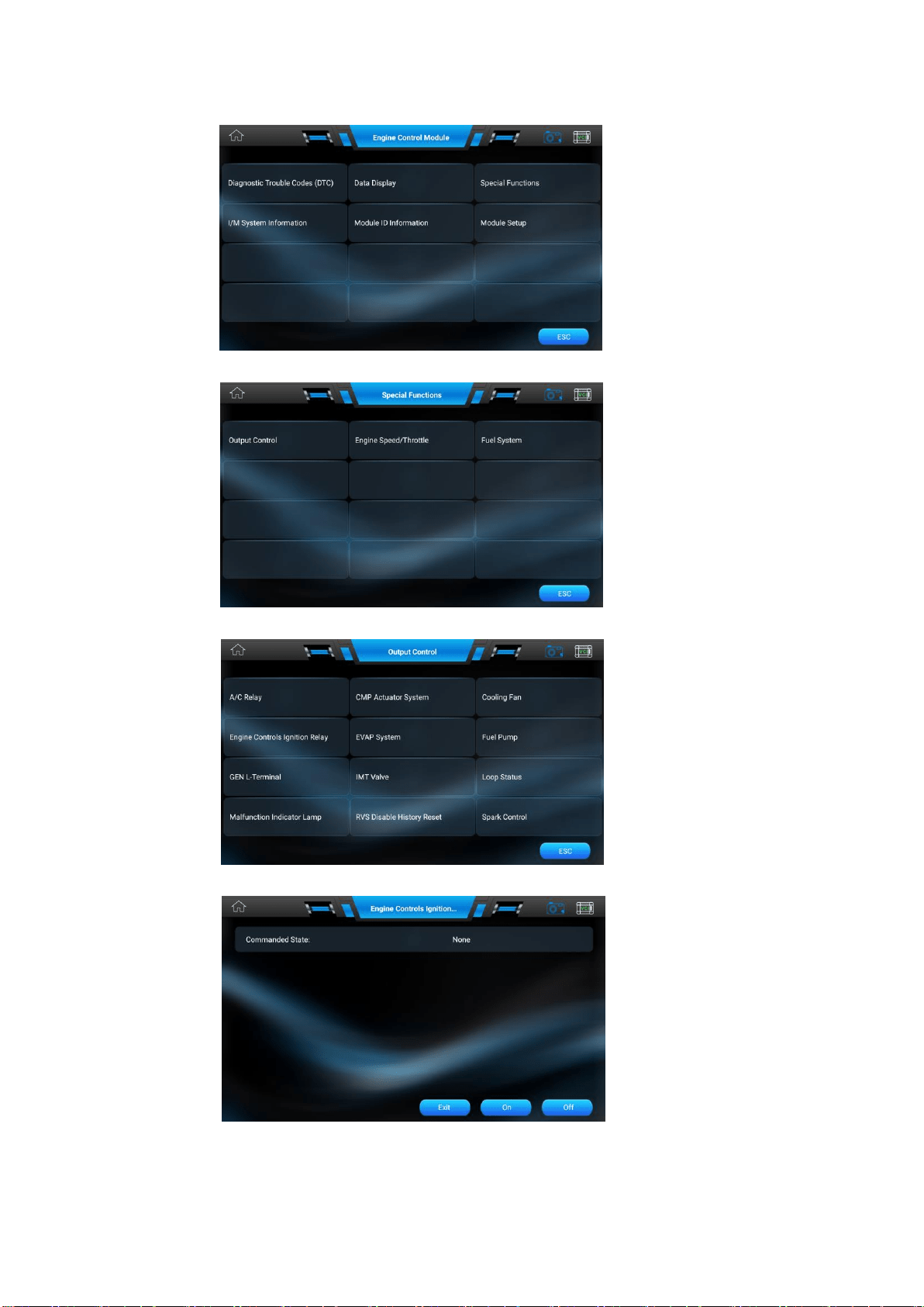
5.2 Special Functions
1. Following the diagnostic function, click the button [Special Functions] from the menu as below:
2. Tap [Output Control] from the menu, the screen will display as below:
3. Tap [A/C Relay] from the menu, the screen will display as below:
4. The screen will display the following information, press On or Off to start the actuator testing:
Note: Follow the screen instruction step by step to continue the diagnostic procedures.
5. Press [Exit] to stop the special function.

Chapter 6 Service Operation
The Service section is specially designed to provide you with quick access to the vehicle systems. There are two
methods to reset service lamp: Manual reset or Auto reset. Auto reset follows the principle of sending command from
the tool to vehicle’s ECU to do resetting. While using manual reset, users just follow the on-screen instructions to
select appropriate execution options, enter correct data or values, and perform necessary actions, the system will
guide you through the complete performance for various service operations.
The most commonly performed service functions include:
1. Oil Reset Service
2. Electronic Parking Brake Reset
3. Steering Angle Calibration
4. ABS Bleeding
5. TPMS (Tire Pressure Monitor System) Reset
6. Gear Learning
7. IMMO Service
8. Injector Coding
9. Battery Maintenance System
10. Diesel Particulate Filter (DPF) Regeneration
11. Electronic Throttle Position Reset
6.1 Oil Reset Service
This function allows you to perform reset for the engine oil life system, which calculates an optimal oil life change interval
depending on the vehicle driving conditions and climate.
This function can be performed in the following cases:
1. If the service lamp is on, you must provide service for the car. After service, you need to reset the driving mileage or
driving time so that the service lamp turns off and the system enables the new service cycle.
2. After changing engine oil or electric appliances that monitor oil life, you need to reset the service lamp.
6.2 Electronic Parking Brake Reset
1. If the brake pad wears the brake pad sense line, the brake pad sense line sends a signal sense line to the on-board
computer to replace the brake pad. After replacing the brake pad, you must reset the brake pad. Otherwise, the car
alarms.
2. Reset must be performed in the following cases:
a) The brake pad and brake pad wear sensor are replaced.
b) The brake pad indicator lamp is on.
c) The brake pad sensor circuit is short, which is recovered.
d) The servo motor is replaced.
6.3 Steering Angle Calibration
To reset the steering angle, first find the relative zero point position for the car to drive in straight line. Taking this position
as reference, the ECU can calculate the accurate angle for left and right steering.
After replacing the steering angle position sensor, replacing steering mechanical parts (such as steering gearbox,
steering column, end tie rod, steering knuckle), performing four-wheel alignment, or recovering car body, you must reset
the steering angle.

6.4 ABS Bleeding
This function allows you to perform various bi-directional tests to check the operating conditions of Anti-lock Braking
System (ABS).
1. When the ABS contains air, the ABS bleeding function must be performed to bleed the brake system to restore ABS
brake sensitivity.
2. If the ABS computer, ABS pump, brake master cylinder, brake cylinder, brake line, or brake fluid is replaced, the ABS
bleeding function must be performed to bleed the ABS.
6.5 Tire Pressure Monitor System Reset
This function allows you to quickly look up the tire sensor IDs from the vehicle’s ECU, as well as to perform TPMS
replacement and sensor test.
1. After the tire pressure MIL turns on and maintenance is performed, the tire pressure resetting function must be
performed to reset tire pressure and turn off the tire pressure MIL.
2. Tire pressure resetting must be performed after maintenance is performed in the following cases: tire pressure is too
low, tire leaks, tire pressure monitoring device is replaced or installed, tire is replaced, tire pressure sensor is damaged,
and tire is replaced for the car with tire pressure monitoring function.
6.6 Gear Learning
The crankshaft position sensor learns crankshaft tooth machining tolerance and saves to the computer to more
accurately diagnose engine misfires.
If tooth learning is not performed for a car equipped with Delphi engine, the MIL turns on after the engine is started. The
diagnostic device detects the DTC P1336 'tooth not learned'. In this case, you must use the diagnostic device to perform
tooth learning for the car.
After tooth learning is successful, the MIL turns off. After the engine ECU, crankshaft position sensor, or crankshaft
flywheel is replaced, or the DTC 'tooth not learned' is present, tooth learning must be performed.
6.7 IMMO Service
An immobilizer is an anti-theft mechanism that prevents a vehicle’s engine from starting unless the correct ignition key or
other device is present.
Most new vehicles have an immobilizer as standard equipment. An important advantage of this system is that it doesn’t
require the car owner to activate it since it operates automatically.
An immobilizer is considered as providing much more effective anti-theft protection than an audible alarm alone. As an
anti-theft device, an immobilizer disables one of the systems needed to start a car’s engine, usually the ignition or the
fuel supply.
This is accomplished by radio frequency identification between a transponder in the ignition key and a device called a
radio frequency reader in the steering column. When the key is placed in the ignition, the transponder sends a signal with
a unique identification code to the reader, which relays it to a receiver in the vehicle’s computer control module.
If the code is correct, the computer allows the fuel supply and ignition systems to operate and start the car. If the code is
incorrect or absent, the computer disables the system, and the car will be unable to start until the correct key is placed in
the ignition.
To prevent the car being used by unauthorized keys, the anti-theft key matching function must be performed so that the
immobilizer control system on the car identifies and authorizes remote control keys to normally use the car.
When the ignition switch key, ignition switch, combined instrument panel, ECU, BCM, or remote control battery is
replaced, anti-theft key matching must be performed.
6.8 Injector Coding
Write injector actual code or rewrite code in the ECU to the injector code of the corresponding cylinder so as to more
accurately control or correct cylinder injection quantity.
After the ECU or injector is replaced, injector code of each cylinder must be confirmed or re-coded so that the cylinder
can better identify injectors to accurately control fuel injection.
6.9 Battery Maintenance System Reset
This function enables you to perform a resetting operation on the monitoring unit of vehicle battery, in which the original
low battery fault information will be cleared and battery matching will be done.
Battery matching must be performed in the following cases:
a) Main battery is replaced. Battery matching must be performed to clear original low battery information and prevent the
related control module from detecting false information. If the related control module detects false information, it will
invalidate some electric auxiliary functions, such as automatic start & stop function, sunroof without one-key trigger
function, power window without automatic function.
b) Battery monitoring sensor. Battery matching is performed to re-match the control module and motoring sensor to
detect battery power usage more accurately, which can avoid an error message displaying on the instrument panel.
6.10 Diesel Particulate Filter (DPF) Regeneration
DPF regeneration is used to clear PM (Particulate Matter) from the DPF filter through continuous combustion oxidation
mode (such as high temperature heating combustion, fuel additive or catalyst reduce PM ignition combustion) to stabilize
the filter performance.
DPF regeneration may be performed in the following cases:
a) The exhaust back pressure sensor is replaced.
b) The PM trap is removed or replaced.
c) The fuel additive nozzle is removed or replaced.
d) The catalytic oxidizer is removed or replaced.
e) The DPF regeneration MIL is on and maintenance is performed.
f) The DPF regeneration control module is replaced.
6.11 Electronic Throttle Position Reset
This function enables you to make initial settings to throttle actuators and returns the “learned” values stored on ECU to
the default state.
Doing so can accurately control the actions of regulating throttle (or idle engine) to adjust the amount of air intake.
Chapter 7 OBDII Operation
A fast-access option for OBD II/EOBD vehicle diagnosis is available on the Vehicle Menu screen. This option presents
a quick way to check for DTCs, isolate the cause of an illuminated malfunction indicator lamp (MIL),
check monitor status
prior to emissions certification testing, verify repairs, and perform a number of other services that are emissions-related.
The OBDII direct access option is also used for testing OBD II/EOBD compliant vehicles that are not included in the
Diagnostics database.
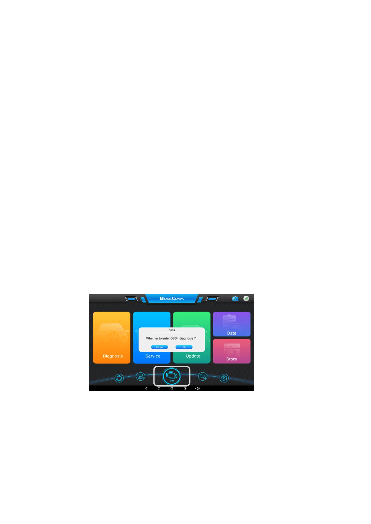
Tap the round big button as below, the system will ask you whether to enter OBDII diagnosis?
7.1 Stored Codes
Stored codes are the current emission related DTCs from the ECM of the vehicle. OBD II/EOBD Codes have a priority
according to their emission severity, with higher priority codes overwriting lower priority codes. The priority of the code
determines the illumination of the MIL and the codes erase procedure. Manufacturers rank codes differently, so expect
to see differences between makes.
7.2 Pending Codes
These are codes whose setting conditions were met during the last drive cycle, but need to be met on two or more
consecutive drive cycles before the DTC actually sets. The intended use of this service is to assist the service
technician after a vehicle repair and after clearing diagnostic information, by reporting test results after a single driving
cycle.

a) If a test failed during the driving cycle, the DTC associated with that test is reported. If the pending fault
does not occur again within 40 to 80 warm-up cycles, the fault is automatically cleared from memory.
b) Test results reported by this service do not necessarily indicate a faulty component or system. If test
results indicate another failure after additional driving, then a DTC is set to indicate a faulty component or
system, and the MIL is illuminated.
7.3 Freeze Frame
In most cases the stored frame is the last DTC that occurred. Certain DTCs, those that have a greater impact on
vehicle emission, have a higher priority. In these cases, the highest priority DTC is the one for which the freeze frame
records are retained. Freeze frame data includes a “snapshot” of critical parameter values at the time the DTC is set.
7.4 Erase Codes
This option is used to clear all emission related diagnostic data such as, DTCs, freeze frame data and manufacturer
specific enhanced data from the vehicle’s ECM, and resets the I/M Readiness Monitor Status for all vehicle monitors to
Not Ready or Not Complete status.
A confirmation screen displays when the clear codes option is selected to prevent accidental loss of data. Select [OK]
on the confirmation screen to continue, or [Cancel] to exit.
7.5 I/M Readiness
This function is used to check the readiness of the monitoring system. It is an excellent function to use prior to having a
vehicle inspected for compliance to a state emissions program. Selecting I/M Readiness opens a submenu with two
choices:
Since DTCs Cleared – displays the status of monitors since the last time the DTCs are erased.
This Driving Cycle – displays the status of monitors since the beginning of the current drive cycle.
7.6 Live Data
This function displays the real time PID data from ECU. Displayed data includes analog inputs and outputs, digital
inputs and outputs, and system status information broadcast on the vehicle data stream.
7.7 O2 Sensor Monitor
This option allows retrieval and viewing of O2 sensor monitor test results for the most recently performed tests from the
vehicle’s on-board computer. The O2 Sensor Monitor test function is not supported by vehicles which communicate using
a controller area network (CAN).
7.8 On-Board Monitor
This option allows you to view the results of On-Board Monitor tests. The tests are useful after servicing or after erasing
a vehicle’s control module memory.
7.9 Component Test
This service enables bi-directional control of the ECM so that the diagnostic tool is able to transmit control commands
to operate the vehicle systems. This function is useful in determining how well the ECM responds to a command.
7.10 Vehicle Information
The option displays the vehicle identification number (VIN), the calibration identification, and the calibration verification
number (CVN), and other information of the test vehicle.
7.11 Vehicle Status
This item is used to check the current condition of the vehicle, including communication protocols of OBD II modules,
retrieved codes amount, status of the Malfunction Indicator Light (MIL), and other additional information may be
displayed.
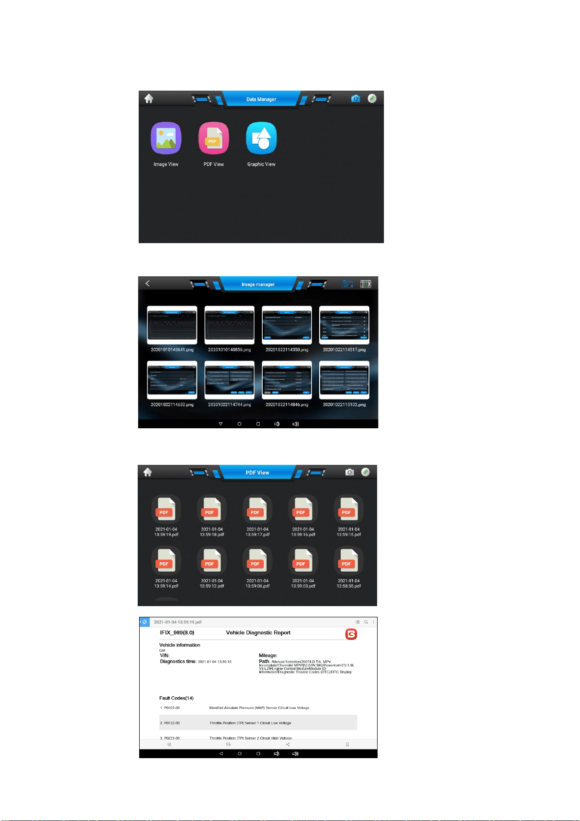
Chapter 8 Data Manager
Data manager operations are based on toolbar controls, details are explained in the following sections. There are
three main functions available: Image View, PDF View and Graphic View
8.1 Image View
The Image section is a JPG database containing all captured screenshot
images.
8.2 PDF View
The PDF View stores and displays all PDF files of saved data. These files are the workshop testing reports
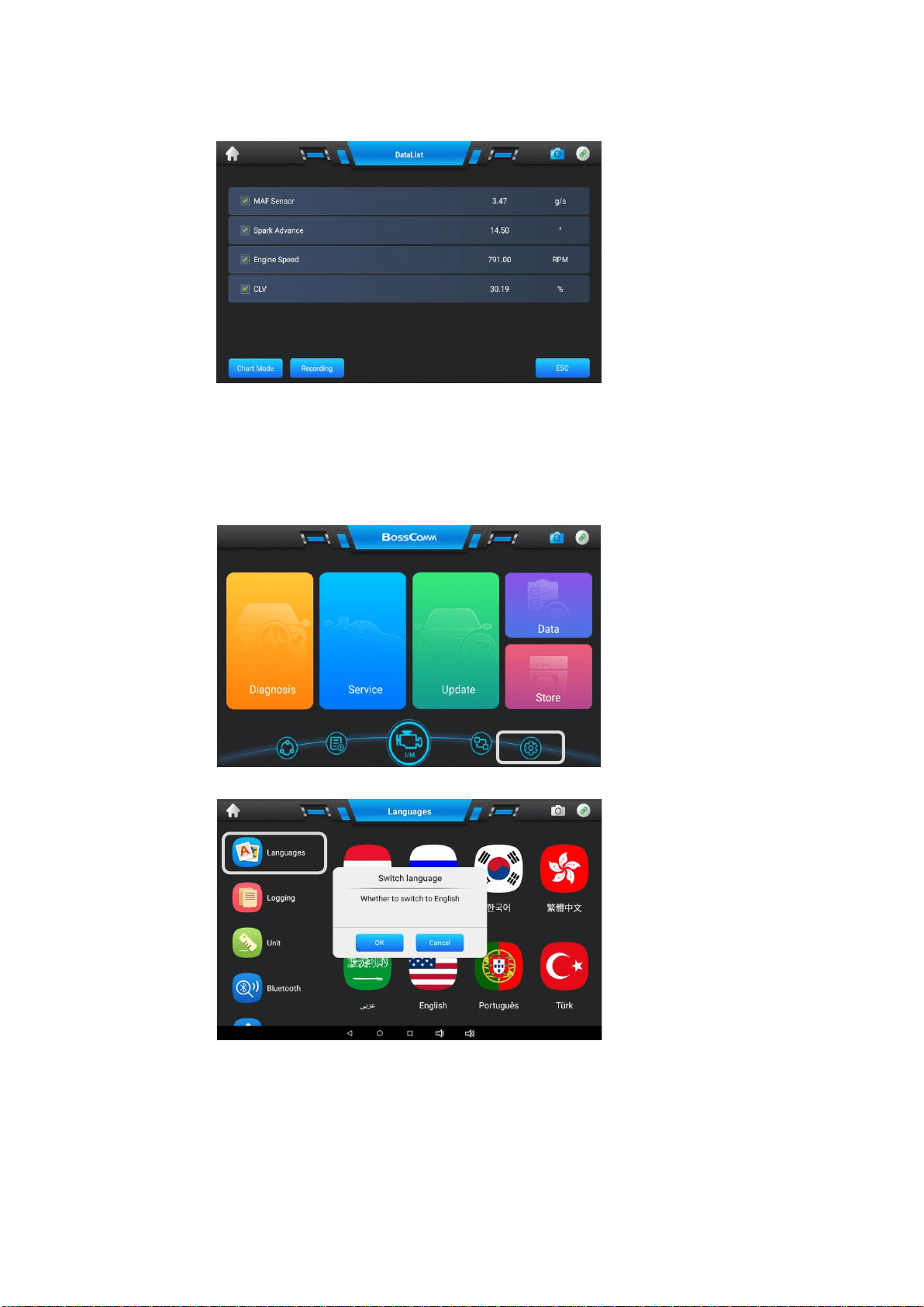
8.3 Graphic View
The Graphic View section allows you to playback the recorded data frames of
live data streams.
Click the checkbox in front of the current line to select the data frame.
Chapter 9 Settings Operations
Setting operations are based on toolbar controls, details are explained in the following sections.
There are four main functions available: Language, Logging, Unit and Bluetooth
9.1 Language
This option allows you to adjust the display language for the IFIX-980 system.
1. Tap the [Settings] application on the IFIX-980 Job Menu:
2. Tap the [Language] option on the left column.
3. Switch the language according to the demands.
Note: IFIX-980 intelligent scan provides English + one local language before delivery.
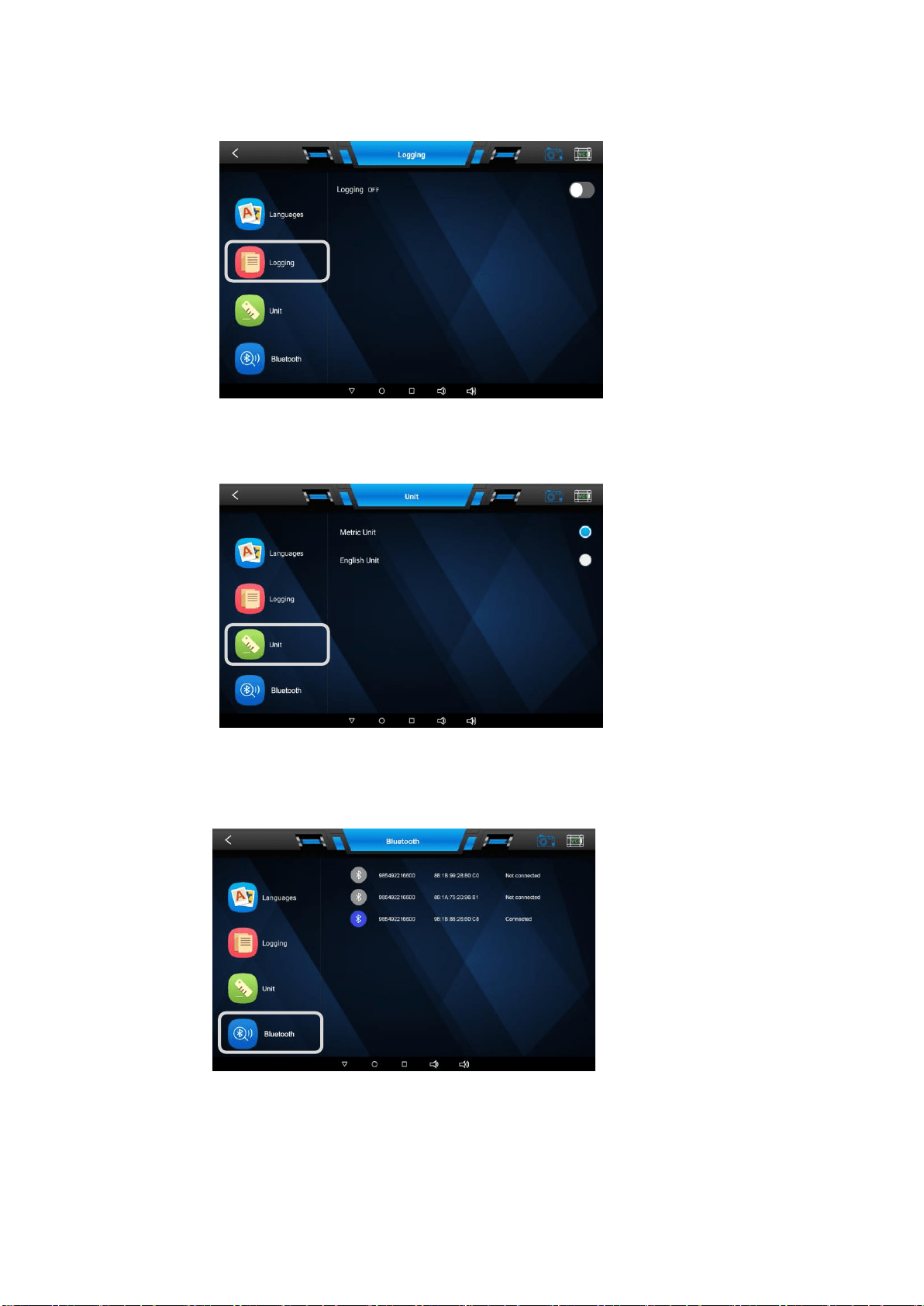
9.2 Logging
The Logging section allows you to launch Support platform directly to view all records of all sent or unsent
(saved) data loggings on the diagnostic system.
9.3 Unit
It allows you to adjust the measurement unit for the diagnostic system.8
1. Tap the [Settings] application on the IFIX-980 Job Menu.
2. Tap the [Unit] option on the left column and click the round button on the right to set the unit.
9.4 Bluetooth
This option allows you to set the Bluetooth pairing with IFIX-980 program. The VCI box needs to be
either connected to a vehicle or to an available power source, so that it is powered up during the
synchronization procedure.
Make sure the IFIX-980 intelligent scan has a charged battery or is connected
to an AC/DC power supply.
NOTE: A VCI box can be paired to only one Display Tablet each time, and once it’s been paired, the device
will not be discoverable for any other unit.
Chapter 10 Workshop Management
The Workshop Management helps you to manage the workshop information,
customer information records, and
keep test vehicle history records, which can be a great assist in dealing with daily workshop business and
improves customer service. There are two main functions available: Workshop Information and Customer
Management.
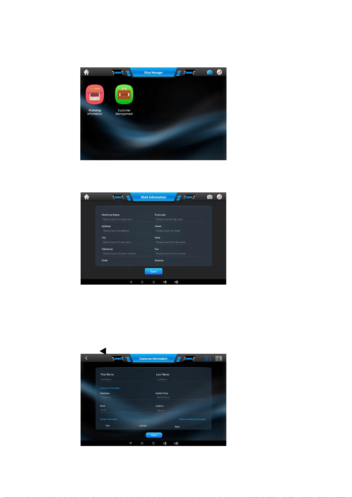
10.1 Workshop Information
The Workshop Information form allows you to edit, input and save the detailed workshop information, such as
shop name, address, phone number and other remarks, which, when printing vehicle diagnostic reports and
other associated test file, will appear as the header of the printed documents.
10.2 Customer Management
The Customer Management allows you to create and edit customer information. It helps you to organize the
associated test vehicle history records and support for the arrangement of daily workshop business.
1. Select [Customer Management].
2. Tap [Add+] to add new customer information and tap the appropriate information on each field.
3. Tap [SAVE] to save the customer information.
4. Tap [+ Add new vehicle information] to add other car information.
5. Tap [Delete] to delete vehicle information
6. Press [ ] on the bottom of the screen to exit the Workshop Information.
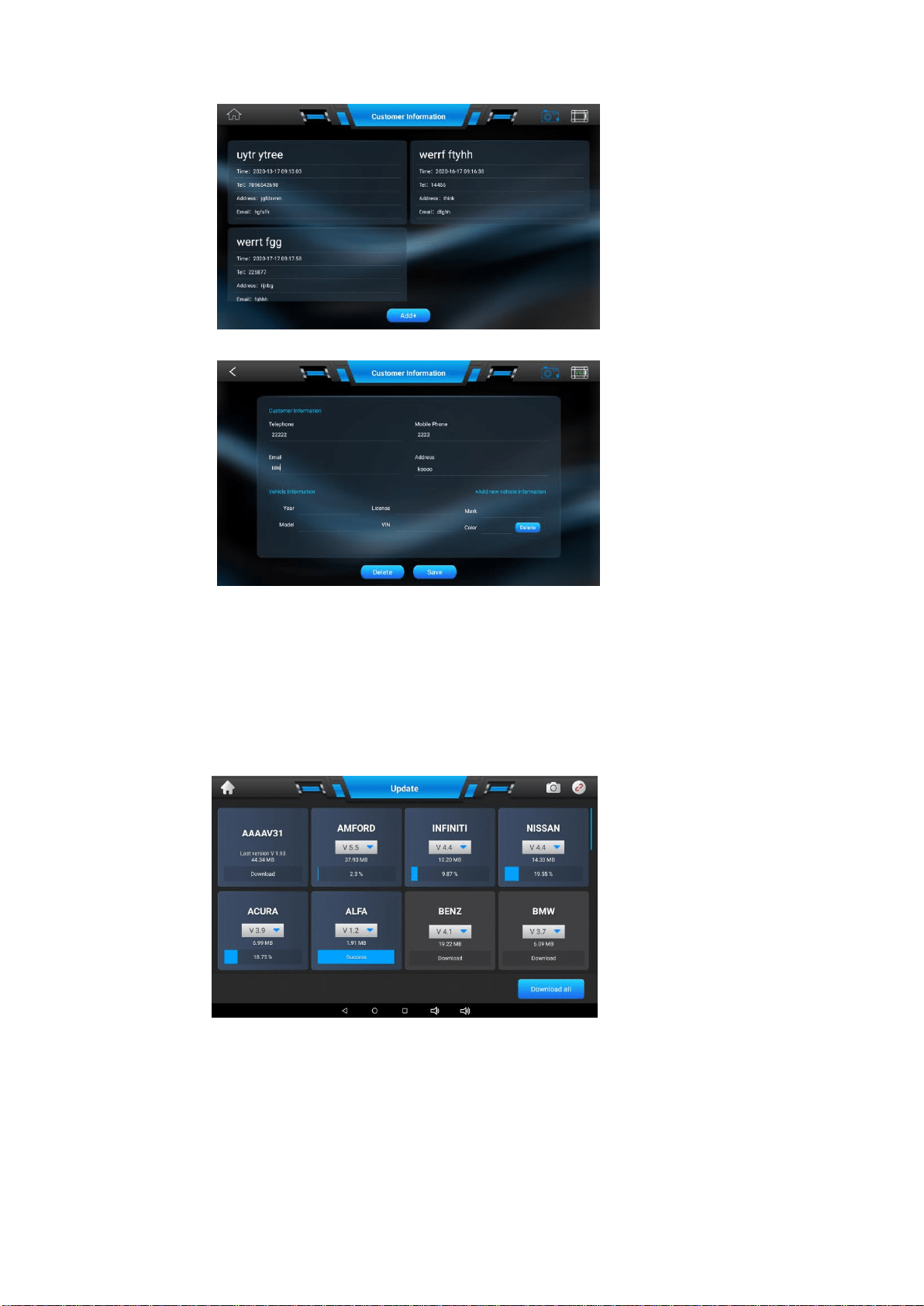
1. Press any selected customer information from the menu of the Customer Information as below
2. The following screen will be displayed:
3. Press [+Add new vehicle information] to add another car in the list
4. Press [Delete] on the top to delete the car information.
5. Press [Delete] on the bottom to delete the customer information.
6. Press [Save] on the bottom to save the customer information
Chapter 11 Software Update
11.1 Update Program
The update program includes the display program AAAAV31 and different car makes diagnostic software package.
For details, please check the picture as below:
11.2 How to Update
Make sure the IFIX-980 intelligent scan is fully charged before the software update and well connected to the Internet
by WiFi. Click any car brand from the list above to start the download or you can click the button [Download All] to
download all software packages once.
Click the blue downward arrow near the software version to select the required software versions from the screen
above.
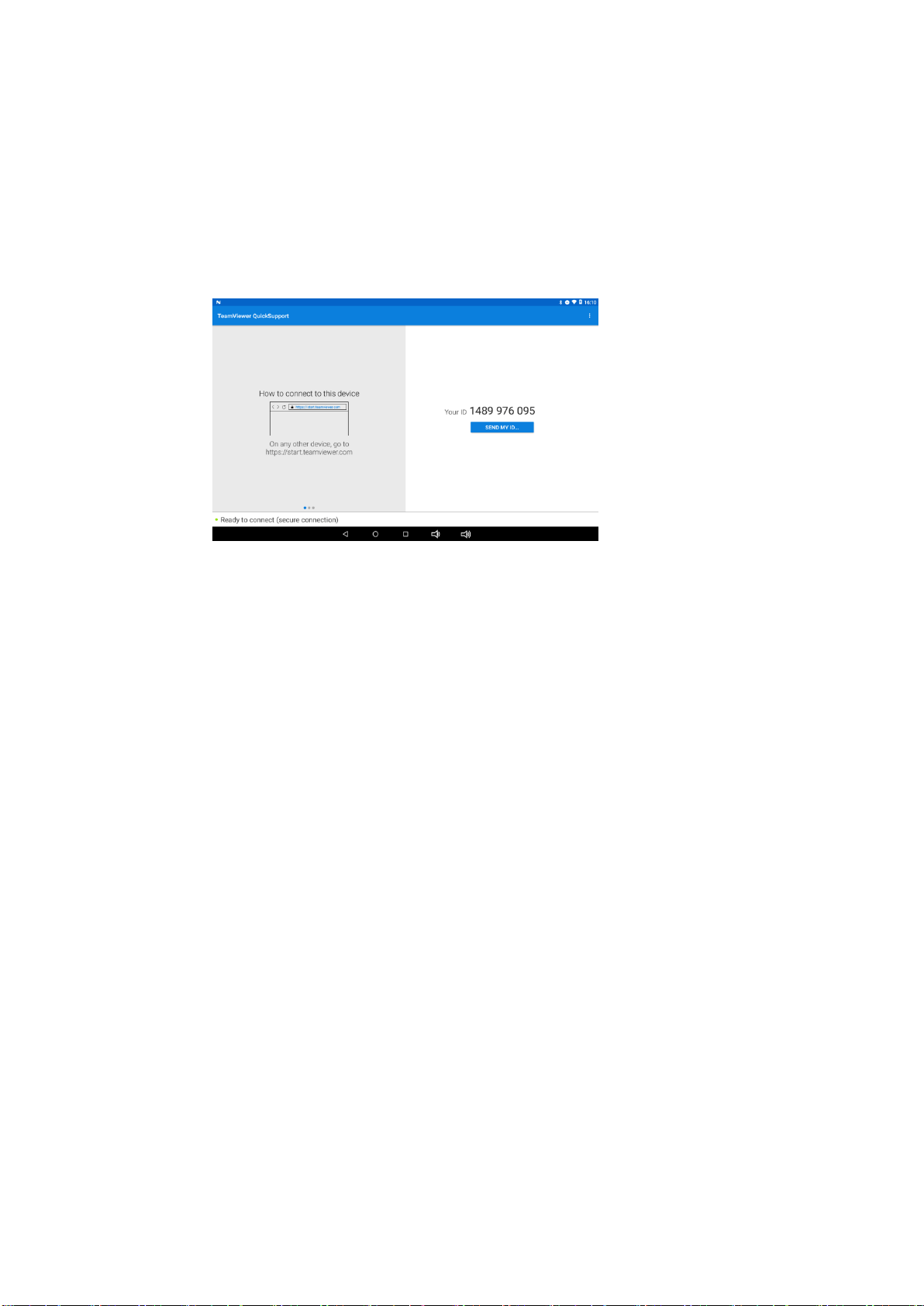
Chapter 12 Remote Desk Operations
The Remote Desk application launches the TeamViewer Quick Support program, which is a simple, fast and secure
remote control interface. You can use the application to receive remote support from BOSSCOMM Tech Support
Center, colleagues, or friends, by allowing them to control your IFIX-980 tablet on their PC via the TeamViewer software.
If you think of a TeamViewer connection as a phone call, the TeamViewer ID would be the phone number under which
all TeamViewer Clients can be reached separately. Computers and mobile devices that run TeamViewer are identified
by a globally unique ID. The first time the Remote Desk application is started, this ID is generated automatically based
on the hardware characteristics and will not change later on.
Make sure the IFIX-980 intelligent scan is connected to the Internet before launching the Remote Desk application, so
that the Display Tablet is accessible to receive remote support from the third party.
Chapter 13 Troubleshooting
When the display tablet does not work properly:
Make sure the tablet has been registered online.
Make sure the system software and diagnostic application software are properly updated.
Make sure the tablet is connected to the Internet.
Check all cables, connections, and indicators to see if the signal is being received.
When battery life is shorter than usual:
This may happen when you are in an area with low signal strength.
Turn off your device if is not in use.
When you cannot turn on the tablet:
Make sure the tablet is connected to a power source or the battery is charged.
When you are unable to charge the tablet:
Your charger maybe out of order. Contact your nearest dealer.
You may be attempting to use the device in an overly hot/cold temperature. Try changing the charging environment.
Your device may have not been connected to the charger properly.
Check the connector.
NOTE: If your problems persist, please contact AUTEK/BOSSCOMM’s technical support
personnel or your local
selling agent.
Chapter 14 About Battery Usage
Your tablet is powered by a built-in Lithium-ion Polymer battery. This means that, unlike other forms of battery
technology, you can recharge your battery while some charge remains without reducing your tablet’s autonomy due
to the “battery memory effect” inherent in those technologies.
DANGER:
The built-in Lithium-ion Polymer battery is factory replaceable only;
incorrect replacement or tampering with the
battery pack may cause an explosion.
Do not use a damaged battery charger.
Do not disassemble or open crush, bend or deform, puncture or shred.
Do not modify or remanufacture, attempt to insert foreign objects into the battery, expose to fire, explosion or
other hazard.
Make sure to use the charger and USB cables only that come together in the package. If you use the other
charger and USB cables, you might incur malfunction or failure of the device.
Only use the charging device that has been qualified with device per the standard. Use of an unqualified
battery or charger may present a risk of
fire, explosion, leakage, or other hazard.
Avoid dropping the tablet. If the tablet is dropped, especially on a hard surface, and the user suspects damage,

take it to a service center for inspection.
The closer you are to your network’s base station, the longer your tablet
usage time because less battery power is
consumed for the connection.
The battery recharging time varies depending on the remaining battery capacity.
Battery life inevitably shortens over time.
Since over charging may shorten battery life, remove the tablet from its charger once it is fully charged.
Unplug the charger, once charging is complete.
Leaving the tablet in hot or cold places, especially inside a car in summer or winter, may reduce the capacity and
life of the battery. Always keep the battery within normal temperatures.
Chapter 15 Service Procedures
This section introduces information for technical support, repair service, and application for replacement or optional
parts.
15.1 Technical Support
If you have any question or problem on the operation of the product, please send email to sales@autektools.com for
help
15.2 Repair Service
If it becomes necessary to return your device for repair, please contact BOSSCOMM local dealer for help.
The following information must be included:
Contact name
Return address
Telephone number
Product name
Complete description of the problem
Proof-of-purchase for warranty repairs
Preferred method of payment for non-warranty repairs
15.3 Other Services
You can purchase the accessories directly from authorized tool suppliers, and/or local distributor or agent.
Your purchase order should include the following information:
Contact information
Product or part name
Item description
Purchase quantity
Chapter 16 Warranty
16.1 12-Month Limited Warranty
AUTEK INC. (the Company) warrants to the original retail purchaser of this IFIX-980 Diagnostic Device, that should this
product or any part
thereof during normal consumer usage and conditions, be proven defective in material or
workmanship that results in product failure within twelve (12) months period from the date of delivery, such defect(s) will
be repaired, or replaced (with new or rebuilt parts) with Proof of Purchase, at the Company’s option, without charge
for parts or labor directly related to the defect(s).
The Company shall not be liable for any incidental or consequential damages arising from the use, misuse, or
mounting of the device. Some states do not allow limitation on how long an implied warranty lasts, so the above
limitations may not apply to you.
16.2 This warranty does not apply to:
a) Products subjected to abnormal use or conditions, accident, mishandling, neglect,
unauthorized alteration,
misuse, improper installation or repair or improper storage;
b) Products whose mechanical serial number or electronic serial number has been removed, altered or defaced;
c) Damage from exposure to excessive temperatures or extreme environmental conditions;
d) Damage resulting from connection to, or use of any accessory or other product
not approved or authorized
by the Company;
e) Defects in appearance, cosmetic, decorative or structural items such as framing and non-operative parts.
f) Products damaged from external causes such as fire, dirt, sand, battery leakage,
blown fuse, theft or
improper usage of any electrical source.
IMPORTANT: All contents of the product may be deleted during the process of repair.
You should create a back-up
copy of any contents of your product before delivering the product for warranty service