INSTRUCTION MANUAL
PLEASE READ THE INSTRUCTION MANUAL CAREFULLY BEFORE
USING THE UNIT.
www.belling.com.au
www.belling.co.nz
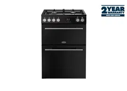
BDU958DBK
90cm Dual Fuel Upright Cooker, Matte Black

2

3
Warning ...........................................4 - 5
General precautions .............................. 4
Abnormal operation ............................... 5
Warning Installation .......................6 - 9
Ventilation ............................................. 6
Positioning ............................................. 6
Fitting the feet ....................................... 7
Balancing the lid .................................... 7
Fitting shelves ....................................... 7
Fitting the oven door handle .................. 7
Gas connection ..................................... 7
Adapting to different types of gas .......... 8
Replacing the hob burners injectors ...... 8
Minimum setting .................................... 8
Electrical connection ............................. 8
Electric ignition ...................................... 9
Safety device ......................................... 9
Technical data and specifications
.... 10
For the user ................................11 - 15
Ventilation ........................................... 11
Igniting the burners ............................. 11
Safety device ....................................... 11
Electrical switch-on ............................. 11
Using the gas hob ............................... 11
Using the electrical grill ....................... 12
Using multifunction electric oven ......... 12
Use of the “TOUCH TIMER” 3 keys .... 13
How to use the oven accessories ....... 15
How to insert the oven shelfs .............. 15
Figures ........................................16 - 17
- Thank you for choosing one of our qua-
lity products, capable of giving you the
very best service. To make full use of its
performance features, read the parts of
this manual which refer to your appliance
carefully. The Manufacturer declines all
responsibility for injury or damage caused
by poor installation or improper use of the
appliance.
- To ensure its appliances are always at the
state of the art, and/or to allow constant
improvement in quality, the manufacturer
reserves the right to make modifications
without notice, although without creating
difficulties for users.
- When ordering spare parts, inform your
dealer of the model number and serial num-
ber punched on your appliance’s namepla-
te, visible inside the warming compartment
(if present) or on the back of the cooker.
FOREWORD
- Refer only to the headings and sections
covering accessories actually installed on
your cooker.
Introduction
Index
AU
Warranty.............................................22

4
Warning
AU
• WARNING: Accessible parts may become
hot during use. Young children should be
kept away.
• Children should be supervised to ensure
that they do not play with the appliance.
• Any spillage should be removed from the
lid before opening.
• Hob surface should be allowed to cool
before closing the lid.
• Ensure that the appliance is switched off
before replacing the lamp to avoid the
possibility of electric shock.
• Danger of fire: Do not store items on the
cooking surfaces.
• CAUTION: The cooking process has to be
supervised. A short term cooking process
has to be supervised continuously.
• WARNING: Unattended cooking on a hob
with fat or oil can be dangerous and may
result in a fire.
• The appliance is not intended for use by
persons (including children) with reduced
physical, sensory or mental capabilities,
or lack of experience and knowledge, un-
less they have been given supervision or
instruction concerning use of the appliance
by a person responsible for their safety.
• Means of disconnection shall be provided
in the fixed wiring in accordance with the
Australian wiring rules.
• During use the appliance becomes hot.
Care should be taken to avoid touching
heating elements inside the oven.
• A steam cleaner in not to be used for clea-
ning this appliance.
• Before replacing the lamp bulb, ensure that
the appliance is switched off.
GENERAL PRECAUTIONS
- Always disconnect the power supply before
any work inside the oven or where live parts
may be accessed.
- Never use the warming compartment for
storing inflammable liquids or items which
do not withstand heat, such as wood, paper,
aerosol cans, matches, etc.
- If taps become stiff to operate over time,
contact the After-Sales service.
- Wash enamelled or chrome-plated parts
with soapy lukewarm water or non-abrasive
detergents.
- Never use abrasives to clean enamelled or
chrome-plated parts.
- Do not use too much water when washing
the hob. Take care that no water or other
substances enter the burner housing holes,
as this may be dangerous.
- The spark plugs for electric ignition must
be kept clean and dry; always check after
use, particularly if there have been drips or
overflows from pans.
- Never close glass lids until the hob burners
or hotplates have cooled completely; it
might shatter or crack.
- Never knock enamelled parts or ignition
spark plugs (where present).
- The main or wall gas tap should be turned
off when the cooker is not in use.
- Never knock enamelled parts or ignition
spark plugs (where present).
- The main or wall gas tap should be turned
off when the cooker is not in use.
- Never lift the cooker by taking hold of the
oven door handle.
- Some modeles are fitted an automatic
cooling motor.
- Any overheating of the outside walls of the
oven will trip the safety device, which will cut
off the power supply. The power supply will
be restored automatically once the outside
temperature of the oven has dropped back
within acceptable limits. However, remem-
ber that if this device is tripped repeatedly,
there is a malfunction (e.g. breakage of the
thermostat which regulates the temperature

5
inside the oven). Call in your service engi-
neer.
-When the oven and grill are switched on for
the first time there may be a typical smell
and smoke may come out of the oven. This
is because of the treatment applied to the
surfaces. Operate the oven empty before
placing foods inside.
No liability is accepted for injury or damage
caused by poor installation or improper use
of the cooker.
Warning:
Servicing should be carried out only by au-
thorised personnel.
- Ensure that the appliance is switched off
before replacing the lamp to avoid the
possibility of electric shock.
- If the surface is cracked, switch off the
appliance to avoid the possibility of electric
shock.
- Do not use harsh abrasive cleaners or sharp
metal scrapers to clean the oven door glass
since they can scratch the glass surface,
which may result in shattering of the glass.
Do not spray aerosols in the vicinity of
this appliance while it is in operation.
Do not use or store flammable materials
in the appliance storage drawer or near
this appliance.
DO NOT MODIFY THIS APPLIANCE.
MAINTENANCE SCHEDULE
We recommend that you clean your appli-
ance as soon as any spillovers occur and that
you keep your appliance clean & free from
any
accumulated
grease/dirt,
particularly
around the spark electrodes. To keep your
appliance
operating
at
peak
performance,
please have it serviced every 2 years by an
authorised person.
ABNORMAL OPERATION
Any of the following are considered to be ab-
normal operation and may require servicing:
- Yellow tipping of the hob burner flame.
- Sooting up of cooking utensils.
- Burners not igniting properly.
- Burners failing to remain alight.
- Burners extinguished by oven door.
- Gas valves, which are difficult to turn.
For
Service
and
Spare
Parts,
Please
see
the rear of this manual for
contact
details.
Warning
AU
6
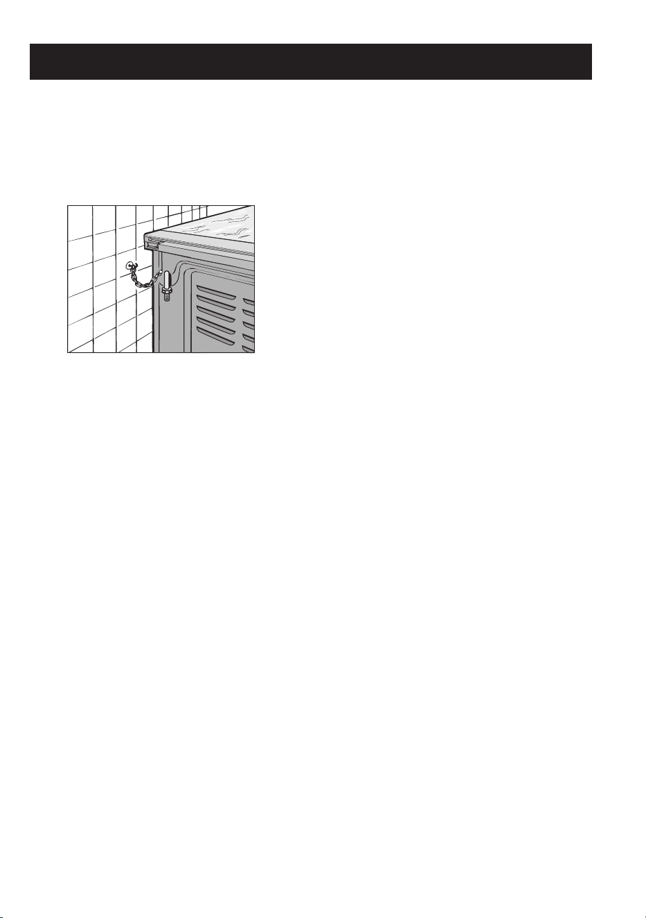
WARNING INSTALLATION
• The cookers must not be installed on a
pedestal.
• Fix the cookers with the chains available
on the back of the appliance and secure
them to the wall.
•
When the oven and grill are switched on for
the first time there may be a typical smell
and smoke may come out of the oven. This
is because of the treatment applied to the
surfaces. Operate the oven empty before
placing foods inside.
•
For
stationary
appliances
permanently
connected to the fixed wiring. Means pro-
viding full disconnection under overvoltage
category III conditions must be incorporated
in the fixed wiring in accordance with AS/
NZS 3000.
INSTALLATION
This appliance shall be installed only by au-
thorised
personnel
and
in
accordance
with
the
manufacturer's
installation
instructions,
local gas fitting regulations, municipal building
codes, water supply regulations, electrical wir-
ing regulations, AS/NZS 5601 - Gas
Installations and
any other statutory
regulations.Before install
ing, ensure that the
appliance is correctly pre-
set for the local
distribution conditions (gas type
and
pressure).The pre-settings of this appliance
are indicated on the nameplate shown on the
cover.This appliance is not connected to a flue
gas extractor device. It must be installed and
connected in accordance with the regulations
in force.When connection to gas and electrical
supply is completed and oven is located in its
final position, the oven must be stabilized by
using the two chains located at the rear of the
oven. (see fig. 11)
Each chain must be firmly attached to the rear
vertical wall behind the oven. The anchor used
to attach the chains to the rear wall must be of
a type suitable for the purpose.
If the appliance is installed between two cup-
boards, drill a hole on each side of the cup-
boards, pass the chains through the holes and
anchor the chains within each cupboard.
MAKE
SURE
THE
ANTI-TILTING
CHAINS
ARE TAUGHT WHEN ANCHORED TO PRE-
VENT THE APPLIANCE TILTING.
If the oven is to be moved for servicing -
THE
CHAINS MUST BE RE-ATTACHED .
ASSEMBLY
The splash back must be fitted to the cooker.
Read the assembly instructions packed with
the splash back to ensure correct fitment.
VENTILATION
The
rooms
in
which
gas
appliances
are
in-
stalled must be well ventilated in order to allow
correct gas combustion and ventilation.
Ventilation must be in accordance with
AS/NZS 5601
- Gas Installations.
In general, the appliance should have adequate
ventilation
for
complete
combustion
of
gas,
proper flueing and to maintain temperature of
immediate surroundings within safe limits.
POSITIONING
Remove the packaging accessories, including
the films covering the chrome-plated and stain-
less steel parts, from the cooker.
Position the cooker in a dry, convenient and
draft-free
place.
Any
adjoining
wall
surface
situated within 200mm from the edge of any
hob burner must be a suitable non-combustible
material for a height of 150mm for the entire
lenght of the hob. Any combustible construc-
tion above the cooker must be at least 600mm
above the top of the burner.The cooker may be
installed alone or between two kitchen units; in
this case, the sides of the units must withstand
Warning Installation
AU

7
a temperature of 75 degrees C and they must
not be higher than the cooker hob.
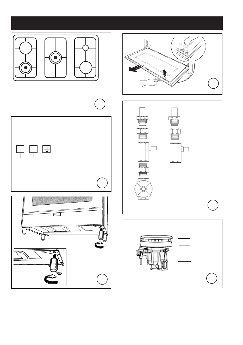
FITTING THE FEET (LEVELLING)
Cookers are equipped with adjustable feet to
be screwed into their front and rear corners
respectively. The feet allow the height of the
appliance to be adjusted, in order to set it flush
with the adjoining unit, to level it with other
worktops and to ensure even distribution of
the liquids in pans. See fig. 3.
BALANCING THE LID
Models equipped with plate glass lids are fit-
ted with special balanced springs. These are
fitted into the hinge to provide smooth, gentle
lid closure.
FITTING SHELVES
Clip wire racks to sides of oven walls (Fig.
10 a).
Slide shelves and trays on the guides as shown
( Fig. 10 b)
FITTING OVEN DOOR HANDLE ( Fig.4 )
- fully open the door.
- apply gentle leverage with the handle of
a fork or spoon in the three recessesi on
the upper of the inside of the door, one at
a time.
- once released from the three springs, the
glass can be extracted from the lower seat
of the inside of the door.
- Fix the handle using the 2 screws provi-
ded.
After fitting oven door handle, repeat the
same procedure in reverse order.
- fit the glass into the lower seat of the in-
side of the door.
- press gently on the upper side of the glass
so that the three pins, with silicone on the
inside, fit into their holes.
- make sure that the door closes complete-
ly.
CONNECTING TO THE GAS SUPPLY
Before connecting the cooker, check that it is
preset for the gas to be used. Otherwise, make
the conversion as described in the section
headed "Adapting to different gas types". The
appliance is factory set for Natural gas. The test
point pressure should be adjusted to 1.00kPa
with the Wok burner operating at maximum.
Ensure that the gas regulator supplied with
the cooker is connected as close as practical
to the gas inlet. The gas connection is male 1/2
BSP and is situated at the right hand rear of
the appliance, 545mm from the bottom of the
cooker ( without legs ) and 34mm fromm the
RHS. See fig. 3
-
For ease of service, the cooker should be
connected with a flexible hose .Ensure the
flexible
hose
complies
with
AS/NZS
1869
(Australian
Approved),
10mm
ID,
class
B
or
D,between
1
-
1.2m
long
and
is
installed
in
accordance with AS/NZS 5601
for a high level connection. The hose should
not be subjected to
abrasion, kinking or
permanent deformation
and
should
be
able
to
be
inspected
along
its entire
length. Unions compatible with the
hose
fittings must be used and connections
tested
for
gas
leaks.
The
fixed
consumer
piping outlet should be at approximately the
same height as the cooker connection point,
pointing
downwards
and
approximately
150mm to the side of the cooker. The hose
should be clear of the floor when the cooker
is in the installed position.
The installer must supply and install a restrain-
ing device (typically chain) utilising the anchor
point provided for the anti tilt chain closest
to the gas connection point. This restraining
device must restrict the appliance movement
to no more than 80% of the hose length to
prevent strain on the hose connections when
the cooker is pulled forward.
- Alternatively, the cooker can be connected
with rigid pipe as specified in AS/NZS 5601
table 3.1
-
After installation, check that all
connections are airtight.
-
For operation with ULPG, check that the gas
pressure is as indicated on the nameplate.
Warning Installation
AU

8
ADAPTING TO DIFFERENT TYPES OF GAS
If the cooker is not already preset to operate
with the type of gas available, it must be con-
verted. Proceed as follows:
- Replace the injectors ( table on page 3);
- regulate the primary air flow;
- regulate the minimum settings.
N.B.: every time you change the type of gas,
indicate the new type of gas on the serial
number label. When converting from Natural
Gas to ULPG ensure that the NG regulatoris
removed and replaced with the Test Point
Assembly. A gas regulator suitable for a sup-
ply pressure of 2.75kPa should be part of the
gas tank supply.
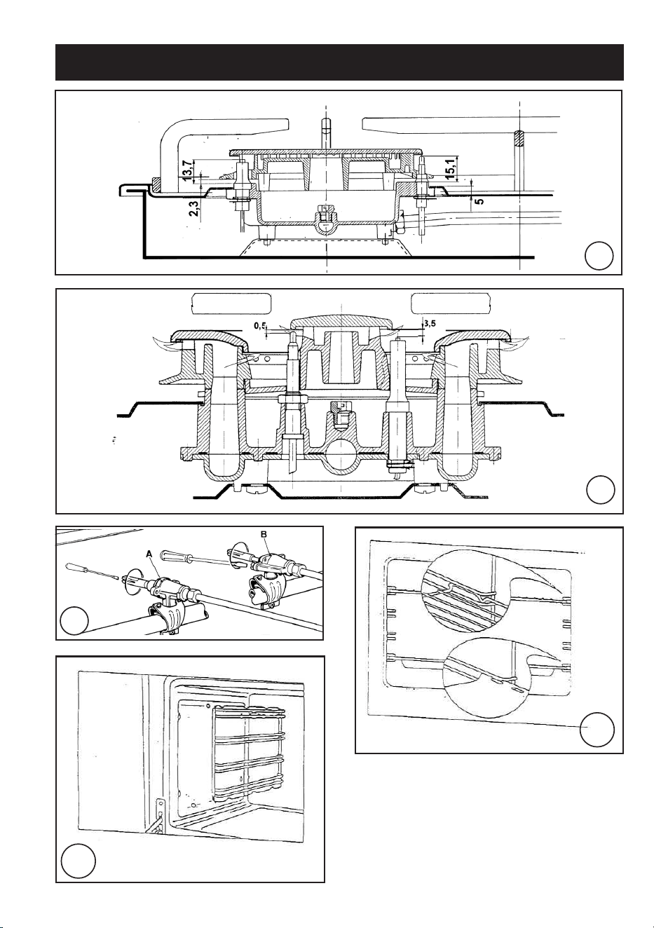
REPLACING THE HOB BURNER
-
INJECTORS (Fig. 6)
- Remove the grid, the burner caps (A), and
the burners (B);
- Unscrew and remove the injector in the
bottom of each injector holder (C);
- replace the injector in accordance with the ta-
ble in page 3, tighten and screw right down;
- check that the system is gas-tight;
- replace the burners, the burner caps and the
grid.
- Never over-tighten the injectors;
- after replacing, check that all the injectors are
airtight.
SETTING HOB BURNER MINIMUM
LEVELS
If the cooker is to work on ULPG, the tap
by-pass must be screwed right down.
The cooker may be equipped with type A taps,
with by-pass inside (accessed by inserting a
small screwdriver into the rod) or type B taps,
with by-pass on the outside on the right (ac-
cessed directly). See figure 8.
If the cooker is to work on natural gas, proceed
as follows for both types of tap:
- Ignite the burner at maximum flame;
- pull off the knob, without using a lever against
the control panel, which might be damaged;
- access the by-pass with a small screwdriver
and back off by about 3 turns (turning the
screwdriver anti-clockwise);
- turn the tap rod anti-clockwise again until it
stops: the burner will be at maximum flame;
- screw the by-pass slowly back in, without
pushing the screw-driver, until the flame has
apparently shrunk to 1/4 of the maximum
size, checking that it is sufficiently stable even
in quite strong draughts.
Check that the burner does not go out when
the tap is turned quickly from the maximum
to the minimum position.
CONNECTING TO THE ELECTRICAL
MAINS
Before making the connection, check that:
- the mains voltage is as indicated on the
nameplate;
- the earth connection is in good working or-
der.
If the socket is not easily accessible, the instal-
lation engineer must provide a switch with a
contact breaking gap of 3 mm or more.
If the appliance power lead is not fitted with a
plug, use an approved standard type, remem-
bering that:
- the green-yellow wire must be used for the
earth connection;
- the blue wire is the neutral;
- the brown wire is live;
- the lead must never touch hot surfaces over
about 75 degrees C;
- replacement leads must be of type HO5RR-F
or H05V2V2-F .
- if the appliance is supplied without lead, using
type HO5RR-F .
IMPORTANT: the manufacturer declines all
liability for damage due to failure to comply
with the regulations and standards in force.
Check that the appliance is correctly connected
to the earth (see diagrams in fig. 2 at the back
of the manual).
Warning Installation
AU

9
FOR COOKERS WITH ELECTRIC IGNITION
The correct gaps between the electrode and
the burner are shown in figures,7a,7b,
If no spark is generated, do not keep on trying
as this might damage the generator.
Possible causes of malfunctions:
- spark plug damp, dirty or broken;
- electrode-burner gap not correct;
- spark plug wire broken or without sheath-
ing;
- spark discharging to earth (to other parts of
the cooker);
- generator or microswitch damaged;
- air has built up in the pipes (particularly if the
cooker has been out of use for a long time);
- air-gas mixture incorrect (poor fuel setting)
THE SAFETY DEVICE
The correct gap between the end of the ther-
mocouple sensor and the burner is shown in
figures 7a,7b.
To check that the valve is working properly,
proceed as follows:
- ignite the burner and leave it to work for about
3 minutes;
- turn off the burner by returning the knob to
off position ( );
- after 90 seconds for hob burners, 60 seconds
for oven and grill burners, turn the knob
pointer to the "on" position;
- release the knob in this position and move a
burning match towards the burner; IT MUST
NOT IGNITE.
Time needed to excite the magnet during igni-
tion: 10 seconds approx.
Automatic tripping time, after flame has been
turned off: not more than 90 seconds for hob
burners; not more than 60 seconds for oven
and grill burners.
IMPORTANT:Before doing any work inside the
cooker, disconnect the mains plug and shut the
gas tap.Never use matches to check the gas
circuit for leaks. If a specific control device is
not available, foam or very soapy water can
be used.When re-closing the hob, check that
the electrical wires of the spark plugs (if pres-
ent) are not close to the injectors, so that they
cannot run across them.
BEFORE LEAVING
Ignite all burners to ensure correct operation
of gas valves, burners and ignition. Turn gas
taps to low flame position and observe stability
of the flame. When satisfied with the appliance,
please instruct the user on the correct method
of operation. In case the appliance fails to
operate correctly after all checks have been
carried out, refer to the authorised service
provider in your area.
AU
Warning Installation
10
Technical data and specifications
AU
HEATING ELEMENT POWERS
bottom element 1.65 kW
top element 1.15 kW
oven circular element 2.5 kW
grill 2.4 kW
fan 25 W
oven light 40 W
tangential cooling fan 22-26 W
Cat.: see nameplate on cover; Class 1 or
2.1
Type “X” cookers
GAS BURNERS (injectors and flow-rates)
EQUIPMENT
Depending on the models, cooker may also
have:
- Safety device for one or more hob
burners
- Electric ignition on top burners
- Electric oven lighting
- Mechanical timer
- Electronic timer
For the LAYOUT OF HOB BURNERS see
the models illustrated in figure 1 at the back
of this manual.
For the ELECTRIC WIRING DIAGRAM see
figure 2 at the back of this manual.
The electrical power is stated on the name-
plate visible inside the warming compartment
(if present) or on the back of the cooker.
A copy of the nameplate is glued to the cover
of this manual.
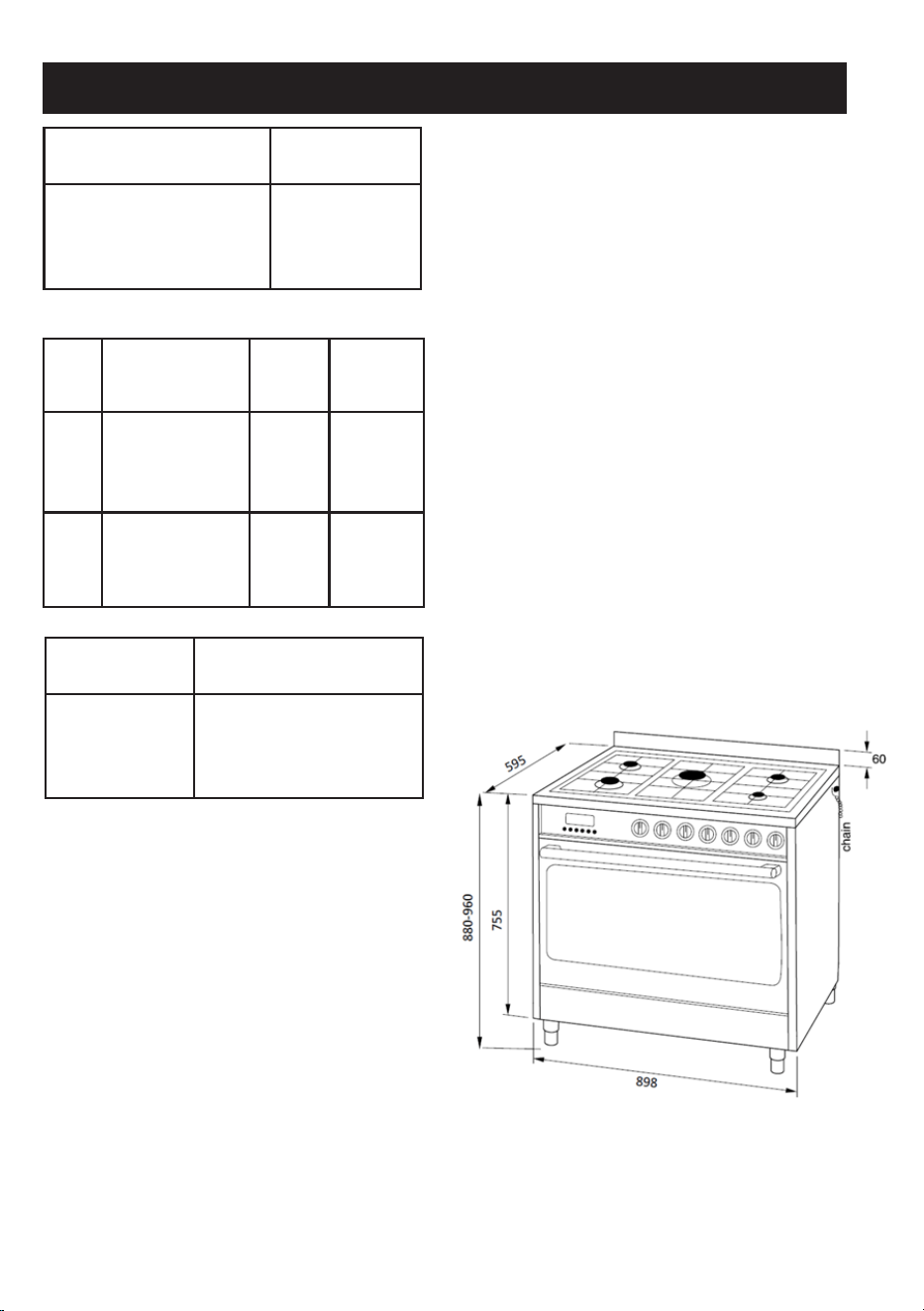
Nominal external
dimensions
Cooker
90x60
Height at hob
Depth with door closed
Depth with door open
Width
cm. 88-96
cm. 59
cm. 100
cm. 89.8
Gas Burner Injector nominal
flow-rate
(MJ/h)
Nat.
Gas
1,00
kPa
Auxiliar (A)
Semi-rapid (SR)
Rapid (R)
Wok B (W)
0,90
1,10
1,50
1,68
4,0
6,0
10,8
14,0
ULPG.
Gas
2,75
kPa
Auxiliar (A)
Semi-rapid (SR)
Rapid (R)
Wok B (W)
0,50
0,65
0,83
0,98
3,1
5,5
8,9
12,4
Usable
dimensions
Electric multifunction
oven
Width
Depth
Height
Volume
cm. 74,0
cm. 43,5
cm. 32,5
l. 121

11
HOW TO USE THE COOKER
VENTILATION
All gas cooking appliances produce heat
and moisture in the rooms where they are
installed. Take care to ensure that the
kitchen is well ventilated; keep the ventilation
openings unobstructed or install an extractor
hood with fan.
In case of intensive or prolonged use, ad-
ditional ventilation may be required; open
a window, or increase the extractor fan
power.
IGNITING THE HOB BURNERS
- Press the knob and turn it anti-clockwise
until it reaches the symbol on the control
panel (maximum flame position);
- at the same time, move a burning match
towards the burner head;
- to reduce the flame, turn the knob further in
the same direction until its pointer is against
the
symbol (minimum flame position).
FOR HOB BURNERS EQUIPPED WITH
SAFETY DEVICE
- Press the knob and turn it anti-clockwise
until it reaches the symbol on the control
panel (maximum flame position);
- move a burning match towards the burner,
keeping the knob pressed right down for
about 10 seconds;
- then release the knob and check that the
burner remains on. Otherwise, repeat the
operation.
SAFETY DEVICE
Burners equipped with this device have the
advantage that they are protected if they ac-
cidentally go out. If this occurs, the supply of
gas to the burner concerned is automatically
cut off, preventing the hazards deriving from
a leak of unburnt gas. The gas supply must
be cut off within no more than 90 seconds
for the hob burners.
FOR COOKERS WITH ELECTRIC IGNI-
TION
All the above applies, except that the match
is no longer required; a spark is obtained
by pressing the button on the control panel
once or more, or by pressing the knob of the
burner to be ignited.
If electronic ignition is difficult with some
types of gas, set the knob on the low (small
flame) setting.
IMPORTANT:
- Difficulty in igniting burners is normal if the
cooker has been out of use for some time.
The air accumulated in the pipes will be
expelled in a few seconds;
- Never allow too much unburnt gas to flow
from the burners. If ignition is not achieved
within a relatively short time, repeat the
procedure after returning the knob to the
off position ( );
HOW TO USE THE HOB BURNERS (Fig.
9)
Use pans of diameter suitable for the burner
type. The flames must not project beyond the
base of the pan. Recommended sizes:
- for auxiliary burners = pans of at least 8 cm
using the adjusting grid supplied with the
cooker
- for semi-rapid burners = pans of at least 14
cm
- for rapid and triple flame burners = pan of
at least 22 cm.
N.B.: Never keep the knob at settings be-
tween the maximum flame symbol
and the
off position ( ).
IMPORTANT:
- Never leave hotplates on without pans,
except when first used; leave for about 10
minutes to dry oil or moisture residues;
- if the hotplate is to be out of use for a long
time, apply a little grease to its painted
surface;
- do not allow spills to burn onto the hotplate,
requiring the use of abrasive cleaners.
For the user
AU
12
HOW TO USE THE ELECTRIC GRILL
- For models with “Multifunction Electric
Oven” only, controlled by two knobs
separately /selector-thermostat), grilling
is permitted with the door closed, with-
out using the front side. Temperatures
above 200°C. must not be used when
grilling with the door closed.
- place the foods on the chrome-plated
shelf;
- insert on the highest runner;
- insert the drip tray on the bottom runner;
- gently close the oven door;
- after a few minutes, turn the food to expose
the other side to the infrared radiation (the
cooking time depends on the type of food
and personal taste).
To see table "Food to be grilled"
The grill must only be used at its full rated
heat.
Food to be
grilled
Time
1st side
minutes
2nd side
Thin pieces of meat
Fairly thick pieces of
meat
Thin fish or fish
without scale
Fairly thick fish
Sausages
Toasted sandwiches
Small poultry
6
8
10
15
12
5
20
4
5
8
12
10
2
15
IMPORTANT: accessible parts may be hot
when the grill is in use! Keep children well
away.
The grill element in the top of the oven is
switched on by turning the thermostat knob
clockwise to the grill symbol on the control
panel.
The red light will come on to show the ele-
ment is in operation.
MULTI-FUNCTION ELECTRIC OVEN
With different heating elements controlled
using a selector switch and regulated by a
thermostat, this oven offers various cooking
methods.
There are three principle sources of heat:
a)
Forced heat diffusion (fan oven).
b) Spontaneous heat diffusion (static
oven).
c)
Infra-red rays (grill).
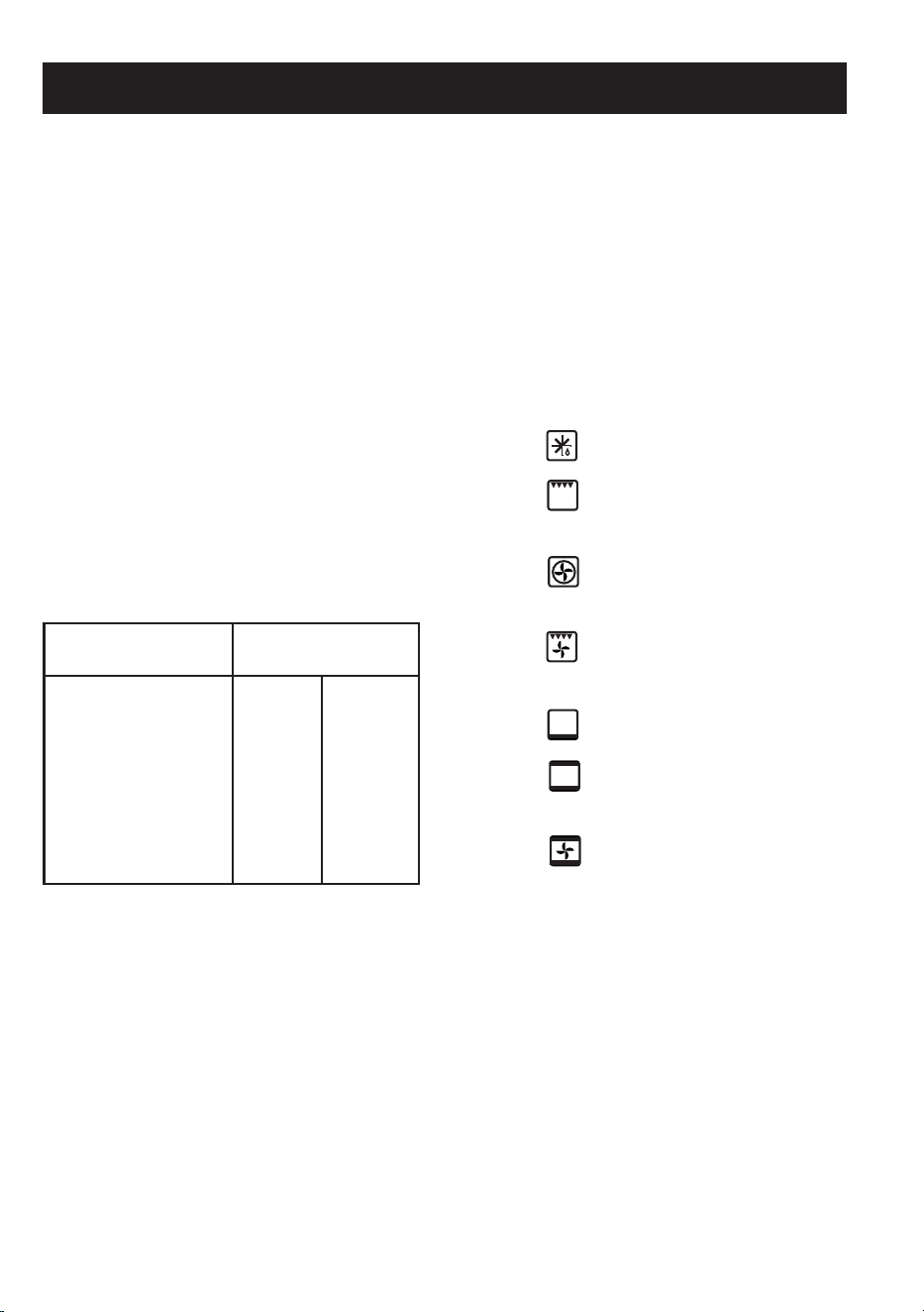
Starting from the 0 (off) position and turning
the selector knob clockwise, the following
settings are obtained:
- symbol :oven light and red light on, fan
running.
- symbol :thegrill function is on,the ther-
mostat knob must be on the maximum
temperature setting.
- symbol :fan oven cooking on one or two
levels, the oven temperature is regulated
by means of the thermostat knob.
- symbol
: the fan grill function is on; the
grill, the top heating element and the fan
inside the oven are all in operation.
- symbol
: the bottom heating element is
one. The oven is heated below only.
- symbol : the top and bottom heating
element are on,the oven temperature is re-
gulated by means of the thermostat knob.
- symbo : full fan cooking is one; the top
and bottom heating elements and the fan
inside the oven are in operation.
In all positions except zero (0) the red warn-
ing light and the oven light are on.
NOTE: The yellow warning light comes on
according to thermostat variations. Before
putting food in to be cooked, the oven should
be pre-heated for at least 10 minutes.
For the user
AU
13
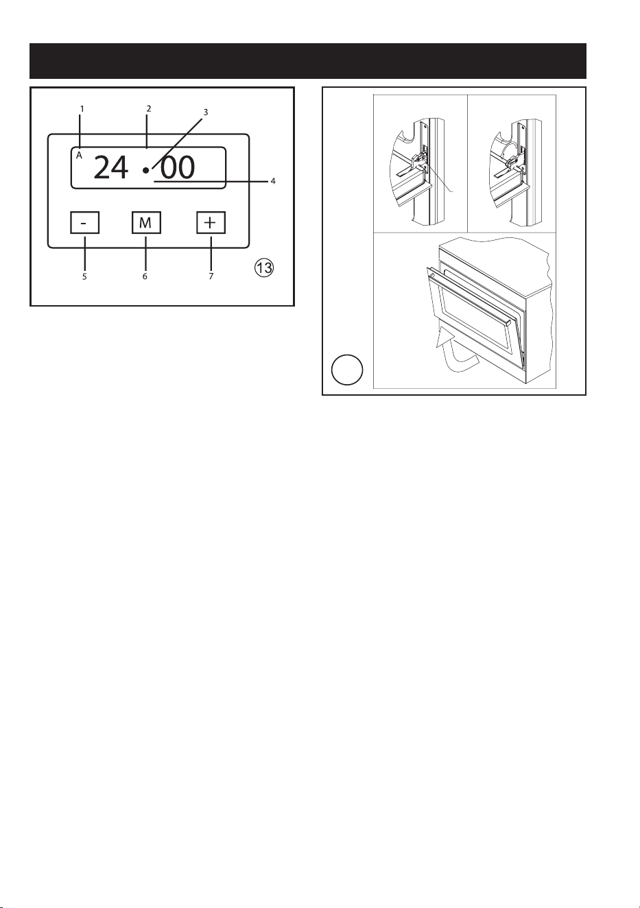
USE OF THE TOUCH TIMER 3 KEYS (fig. 13)
The first start up
The numbers and the A letter on the display
are blinking when the oven is switched on
for the first time, or after a power cut the
appliance cannot be operated in this con-
dition. To set the hour and/or to enable the
appliance to operate press the M key for at
least 2 seconds: the A letter turns off and
the numbers now are steady on the display.
The dot (3) starts blinking: press the - or +
key to set the hour.The hour is accepted by
the programmer just few second after having
released the key.
N.B. the appliance can be correctly used for
cooking only when you will see on the display
the symbol (2).
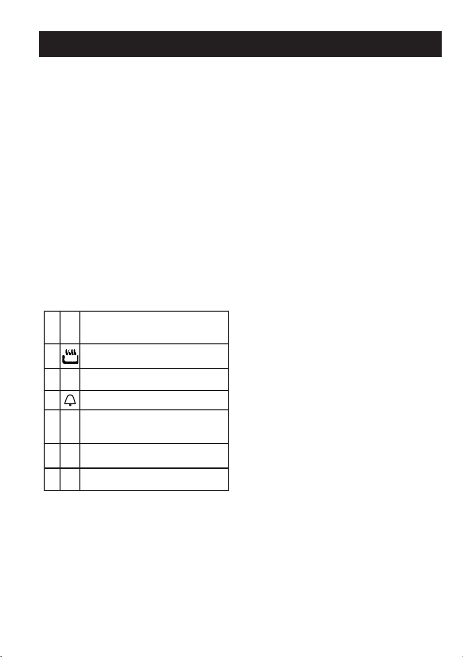
The symbols on the display
1 A*
Automatic programme is working.
(* in some models there is the writing “ Auto
instead of A)
2
The appliance is ready for manual use (not
automatic).
3 •
When blinking, the programmer is in setting
hour mode.
4
Timer set.
5 -
Decreasing numbers when setting the
timer. Also for choose your desired sound
level (3 levels available)
6 M
“Mode” key to access the programming
options of the programme.
7 + Increasing numbers when setting the timer.
Timer
The purpose of the timer is just of a sound
signal, which can be set for a maximum time
of 23h 59min. Once elapsed the set time,
the (4) symbol turns off and a sound signal
is heard; this sound set off automatically in
7min, or you can stop it by pressing any key
of the programmer. To set the timer press
the M key for 2 seconds, or anyway just to
see the (4) symbol blinking. Set the timer by
using the + or - keys. Release the + or - key
when you have matched your desired time.
In a few seconds the current time appears
on the display together with the (4) symbol.
The countdown starts immediately from
now on.
Semi-automatic cooking
Cooking time
Once having selected a cooking function
and set the desired temperature, press the
M key for a 2 seconds time to access the
programming mode. The (4) symbol appears.
Release and press again the M key.On the
display, the A symbol starts blinking and the
“dur” writing appears on the display, then it
changes to 0*00.
Set the cooking time with the - or + keys.
(max available time: 10h).
The selected time is automatically processed
by the programmer in a few seconds, or you
can also touch the M key many times just
to see again the current time.The A and
(2) symbols will be on the display.Once the
set cooking time is finished, a sound will be
heard and the oven automatically switches
off. Please see the following paragraphs
about how to disable the sound alarm and
restarting the oven.
End of cooking
Once having selected a cooking function and
set the desired temperature, touch the M
key to access the programming mode for at
least 2 seconds.The (4) symbol switches
on. Release and touch again the M key.On
the display the A symbol starts blinking and
the writing “dur” appears. Touch again the
M key. On the display the writing “End”
appears. The last one changes few seconds
after with the symbol 0*00.
Set the end of cooking time with the keys - or
+. (maximum available time: 10h 00m). The
selected time is automatically processed by
the programmer in a few seconds, or you
can also touch the M key many time just
to see again the current time. The cooking
For the user
AU

14
immediately starts, while on the programmer
display the current time is shown again in a
few seconds.
The A and (2) symbols will be on the display.
Once the set end of cooking time is finished,
a sound will be heard and the oven automat-
ically switches off. Please see the following
paragraphs about how to disable the sound
alarm and restarting the oven.
Automatic cooking
Set a cooking time following the instructions
on the cooking time paragraph, then set the
end of cooking time following the instruc-
tions on the previous paragraph.(maximum
available end of cooking time 24h).The oven
automatically switches on at a determined
time which is the difference between the end
of cooking time and the cooking time.During
the waiting time before cooking, which goes
from the oven start to the heating, on the
display appears the A symbol to show that an
automatic program is on and the current time.
The oven on is marked by the (2) symbol.
Once the set end of cooking time is finished,
a sound will be heard and the oven automat-
ically switches off. Please see the following
paragraphs about how to disable the sound
alarm and restarting the oven.
How to disable the sound alarm
To disable the sound just touch one of the
keys.
Operating again the oven
Once a semi-automatic or automatic cooking
has expired, on the display appear the cur-
rent time and the blinking A symbol. In this
condition, the heating elements and the light
bulb of the oven are disabled.
To enable again the oven, just touch and
keep the M key up to see the symbol (2) on
the display and the A symbol disappears.
OTHER PROGRAMMER FUNCTIONS
How to delete a cooking time -
Semi-Automatic or Automatic
To delete a semi-automatic or automatic
cooking program, with the A symbol on,
touch together the - and + keys for a least 2
seconds or anyway up to see the (2) symbol
and the disabling of A symbol.
How to delete the countdown timer
To delete the counting of the timer, which
symbol is (4), touch the M key for at least 2
seconds or anyway up to see the (4) symbol
blinking. Touch together the - and + keys.
Checking the function settings
The set or remaining time of every cooking
function of the programmer can be recalled
to the display by entering in program mode
with the M key. Touch and keep the M key
for almost 2 seconds or anyway up to see
the (4) symbol. The remaining time appears
on the display, or a series of zero numbers if
the timer is disabled. Touch again the M key.
On the display appears the “dur” writing, then
alternately the remaining time or a series of
zero number (disable timer).
By touching again the M key, the end of
cooking time appears together with the
“End” writing.
How to change the current time or the
sound level
With the programmer in standard mode, the
(2) symbol is on touch together the - and +
keys for at least 2 seconds or anyway up to
see the dot (3) blinking.
To update the hour on the display:
Touch the - and + keys.
To change the sound level:
Touch the M key.
On the display appears the writing : to n...
followed by a number.
Select with the - key your preferred
sound
For the user
AU

15
level.
Note: number 1 is referred to the highest
sound level. The available levels are 3.
Warning:
Power cut causes the loss of any program,
even the clock.
That means the programmer will have to be
set again.
HOW TO USE OVEN ACCESSORIES
- The oven shelf is designed to take normal
oven dishes for cooking sweets or roasts,
or is used without a pan for cooking foods
under the grill.
- The drip pan under the grill is used to col-
lect juices, which drip from the food that
is cooked directly on the grill. The drip pan
can also be used for cooking.
HOW TO INSERT THE OVEN SHELF
To insert the oven shelf properly, just slide
the shelf following the relevant side supports.
To pull the shelf out, it is necessary to gently
lift it out of the side racks and then pull out
the shelf.
REMOVING THE OVEN DOOR
The door can be removed to clean the oven
in a easier way following this instructions:
1) Open the door completely.
2) Turn the two levers "B" bringing them from
position 1 to position 2 (see fig. 15).
3) Close the door slowly to a stop, grab it
with both hands from side to side, close
it further and pull it by lifting it upwards.
4) To replace the door you must follow the
procedure in reverse order, insert the two
hinges in their seats and open the door
completely.
5) Turn the two levers "B" bringing them back
in position 1.
6) Close the door normally.
For the user
AU
16
5
U-LPG
Nat.Gas
Figures
CONNECTION DIAGRAM
TWO-PHASE
Wire gauge
> 3,5 kW 3x2,5 mm
2
2,2 - 3,5 kW 3x1,5 mm
2
0 - 2,2 kW 3x1 mm
2
1 2
L N
2
3
6
A
B
C
4
A = AUXILIARY
R = RAPID
TC(W) = WOK
1
R
R
A
CT
CT
17
7b
Figures
7a
8
10a
10b
18
Figures
POSITION 2POSITION 1
15
B
19
16
Figures
If the cooker is INSTALLED between two cupboards you
must drill a 16mm hole level to the safety chain height
on either cupboard as far back as possible, locate the
cooker into position and pass the safety chains through
the 16mm holes, with the cooker in the final position pull
both safety chains and secure them to the inside of the
cupboard with two screws on each safety chain.
Please test that the cooker does not tilt forward.
20
Figures
17
Loose Chain
Hole in cabinet too large,
Allowing the upright oven to tilt
forward
X
X
Incorrect Installation
Accidental Tipping
Chains are provided as a preventative
measure against accidental tipping.
T
hes
e
chains must be fitted as part of
the installe
rs complian
ce.. Failure for
your install
er to
fit ch
ains in accordance
with the r
elevant ins
tallation code will
make t
he i
nstallation of your upright
cooker non
-compli
ant and class as an
ill
eg
al instal
lation.
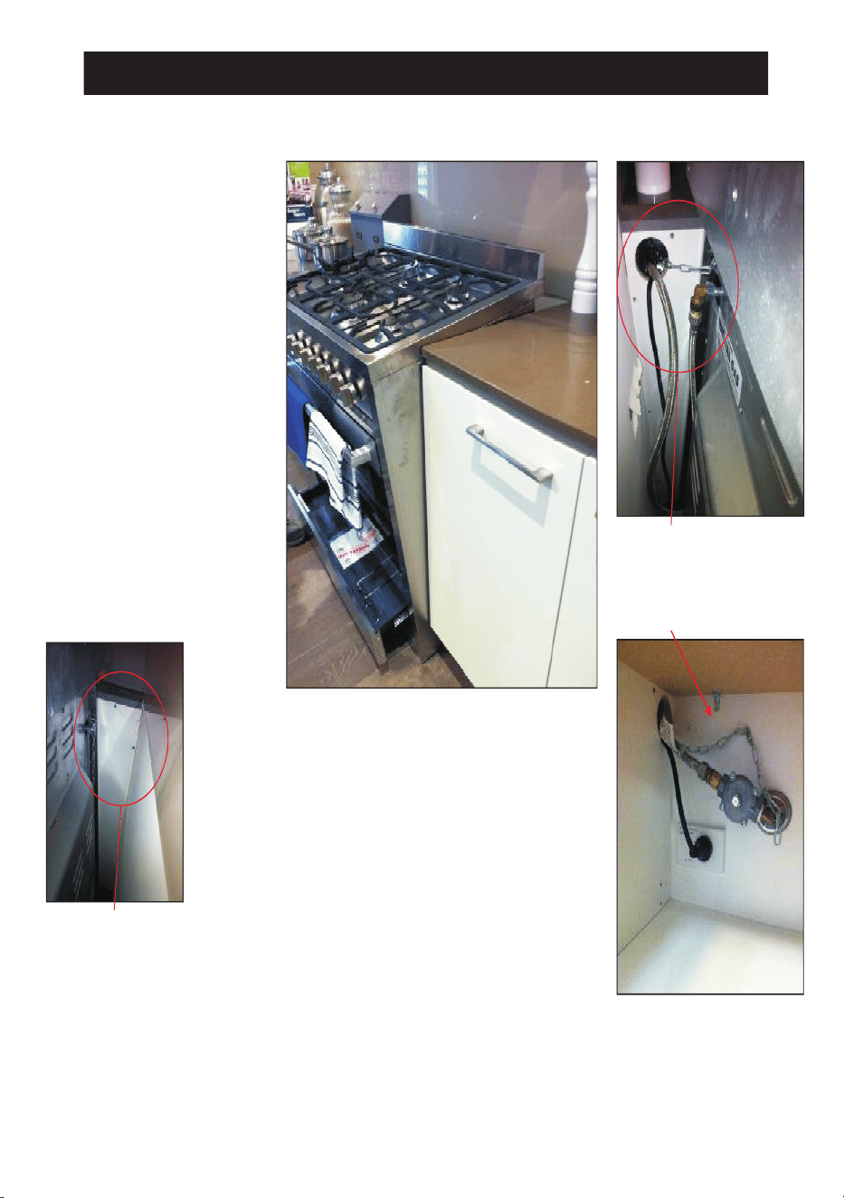
Incorrect Installation
The photographs on this page are of one
single kind of incorrect installation
(although there are many) which does not
have t
he chai
ns suf
ficie
ntly secured, figure
1. s
hows an example of how far forward an
oven can tip when not secured properly.
Note: Correct installation is part of the
installers compliance
Left Side of oven, chain
not attached
X
Unfortunately the example on this page is the way many installers are
installing uprights. The
y may believe that they are using the correct method by
putting the chain through a hole into the adjacent cabinet and screwing the
chain to the back wall but it will not work if not done properly.
Putting the chain into the adjacent cabinet is the preferred method, provided
there is no slack
ness
in the chain..
Some inst
allations only
have a
single
chain affix
ed. Bo
th chai
ns m
ust be fix
ed
as part of the installers compliance. Failure to fix both chains will make the
installation non compliant.
Figure 1.
21
Figures
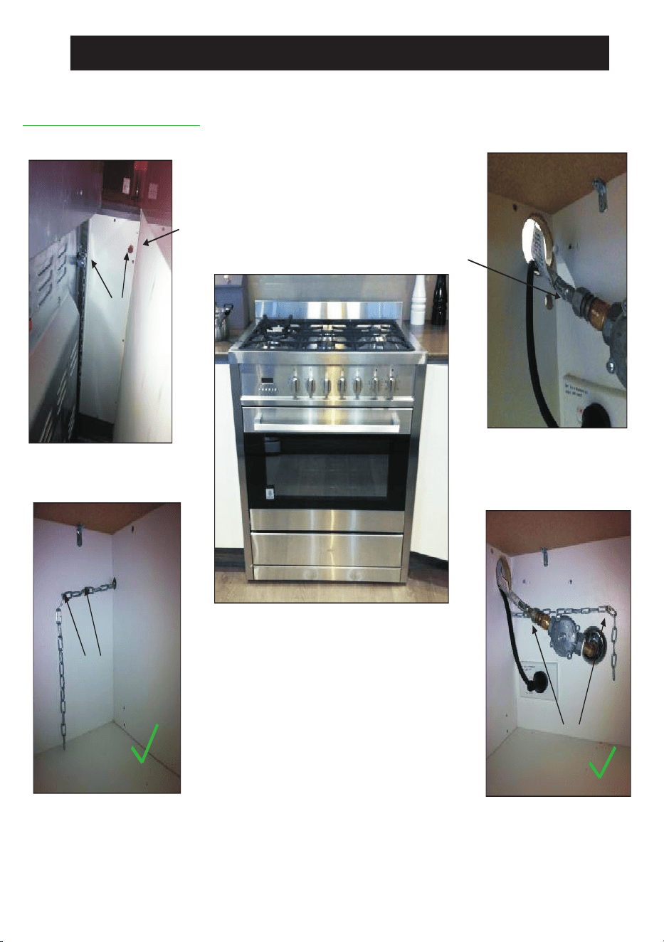
18
Corre
ct Chain In
stallation
In
order to prev
ent th
e oven fr
om tippin
g forward a
s shown on t
he pr
evious page
, we
need
to mak
e sure b
oth chains
provided with th
e oven
are u
sed.
O
n the lef
t sid
e of th
e oven a
16
mm drill bit
was us
ed to
drill th
rough the
ca
binetry
into the
adjacent cabinet, as you can see the hole has not been drilled hard up against the wall
because there is a 16mm board at the rear of the cabinet. The height of the hole from the
floor is level with where the chain attaches to the oven.
The right side has been drilled much the same,, a new hole has been drilled below the gas
and po
wer sup
ply hole.
Hole and
Chain Level.
Once the holes have been drilled the chains can be fed through and the upright can be
fitted into position.
The chains then need to be pulled as tight as possible from inside the cabinet while at
t
he same t
ime being
fixed to
the rear of
the ca
binet using
a self d
rilling
wood
screw. It is
b
etter to have the screw fixed closer to the hole for better support. The left and right
side examples shown have two extra screws attached to the chain which makes the
inst
allation n
eater by
keep
ing t
he chain of
f the
shelf a
way f
rom the gas an
d electri
city
s
upply, th
ey will als
o provid
e ad
ded su
pport.
At this p
oint th
e oven will
be secur
ed in locati
on a
nd wil
l not mo
ve for
ward at al
l, It is
recommended that all upright oven chains be fitted in this way.
Instal
lation
forms
part of the in
stallers co
mpliance and that in line with AGA
regulations chains are designed to be installed to prevent cooker from tilting.
They
are n
ot desig
ned to
repl
ace parental
sup
ervision whe
n the c
ooker
is in
use.
Chain fixed in two
loc
ations.
Chain fixed in
two locations
Left Side
Right Side

MANUFACTURER GUARANTEE
This warranty is provided in Australia by Glen Di
mplex Australia Pty Limited ABN 69 118 275 460
(Phone number 1300 556 816) and in New Zealand by Glen Dimplex New Zealand Limited NZBN
9429000069823 (Phone number 09 274 8265) in respect of the Belling Design product.
1. Belling Design Express Warranty
Subject to the exclusions below, we warrant that the product will not have any electrical or
mechanical breakdowns within:
a) In the case of Belling Design products used for personal, domestic or household purposes,
a period of 5 years from the date the product is purchased as a brand-new product from a
retailer located in Australia / New Zealand.
b)
In the case of Belling Design products used for purposes ot
her than personal, domestic or
household purposes (including business or commercial use), a period of 90 days from the
date the pro
duct is purchased as a brand-new product from a retailer located in Aust
ralia /
New Zealand. Belling Design products are designed and intended for domestic use only;
and
c)
All warranty repairs must be carried out by Glen Dimplex or their nominated service ag
ent
Note: w
arranty periods detailed above may vary in line with agreements with select retail and
builder partners and ma
y differ between Australia and New Zealand.
The benefits conferred b
y this express warranty are in addition to the Consumer Guarantees
referred to in section 3 and any other statutory rights you may have under the Australian / New
Zealand Consumer Law and/or othe
r applicable laws.
2. Warranty exclusions
This express warranty does not apply where:
a)
The product has been installed, used or operated otherwise than in accordance with
the
product manual or other
similar documentation provided to you with the product;

b) The product requires repairs due to damage resulting from accident, misuse, incorrect
installation, insect or vermin infestation, improper liquid spillage, cleaning or maintenance,
unauthorised modification, use on an incorrect voltage, power surges and dips, voltage
supply problems, tampering or unauthorised repairs by any persons, use of defective or
incompatible accessories or exposure to abnormally corrosive conditions, events
independent of human control which occurred after the goods left the control of Glen
Dimplex;
c) The repair relates to the replacement of consumable parts such as fuses and bulbs or any
other parts of the product which require routine replacement;
d) You are unable to provide us with reasonable proof of purchase for the product;
e) the breakdown occurs after the expiry of the express warranty period set out in section 1 or
f) the product was not purchased in Australia / New Zealand as a brand-new product.
3. Consumer guarantees
Our goods come with guarantees that cannot be excluded under the Australian / New Zealand
Consumer Law. You are entitled to a replacement or refund for a major failure and for compensation
for any other reasonably foreseeable loss or damage. You are also entitled to have the goods
repaired or replaced if the goods fail to be of acceptable quality and the failure does not amount to a
major failure.
4. How to make a claim
You may make a claim under this warranty through our website, contacting our customer care line
or via email. Contact details for Glen Dimplex Australia and New Zealand can be found at the end of
this document
To make a valid claim under this warranty, you must:
a) Lodge the claim with us as soon as possible and no later than 14 days after you first become
aware of the breakdown;
b) Provide us with the product serial number;
c) Provide us with reasonable proof of purchase for the product. This can take the form of a
store receipt, new home handover form or other payment receipt documentation; and

d) If required by us, provide us (or any person nominated by us) with access to the premises at
which the product is located at times nominated by us (so that we can inspect the product).
5. Warranty claims
If you make a valid claim under this warranty and none of the exclusions set out in section 2 apply,
we will, at our election, either repair the product or replace the product with a product of identical
specification (or where the product is superseded or no longer in stock, with a product of as close a
specification as possible).
Goods presented for repair may be replaced by refurbished goods of the same type rather than
being repaired. Refurbished parts may be used to repair the goods.
Products are designed and supplied for normal domestic use. We will not be liable to you under this
warranty for business loss or damage of any kind whatsoever.
Glen Dimpl
ex Australia Pty Ltd Glen Dimplex New Zealand Ltd
www.glendimplex.com.au www.glendimplex.co.nz
Australia New
Zealand
Ph: 1300 556 816 Ph: 09 274 8265

NOTES
______________________________________________________
______________________________________________________
______________________________________________________
______________________________________________________
______________________________________________________
______________________________________________________
______________________________________________________
______________________________________________________
______________________________________________________
______________________________________________________
______________________________________________________
______________________________________________________
______________________________________________________
______________________________________________________
______________________________________________________
______________________________________________________
______________________________________________________
______________________________________________________
______________________________________________________
READ T
HE INSTRUCTION BOOKLET BEFORE INSTALLING AND USING THE APPLIANCE.
The manufacturer will n
ot be responsible for any damage to property or to persons caused by
incorrect installation or improper use of the appliance.
The manufacturer is not responsible for any inaccuracies, due to printing or transcription errors,
contained in this manual. In addition, the appearance of the figures reported is also purely
indicative.
The manufacturer reserves the right to make changes to its products when considered necessary
and useful, without affecting the essential safety and operating characteristics.
Glen Dimplex constantly seeks ways to improve the specifications and designs of their products.
Whilst every effort is made to produce up to date literature, this document should not be regarded
as an infallible guide. Actual product only should be used to derive cut out sizes.
All appliances must be installed by a qualified person/s with adherence to the relevant electrical,
plumbing and building codes, with compliance being issued as required by state or national
legislation.
Additionally, all upright cookers must have the anti-tilt device installed correctly in adherence to the
relevant standards by a licenced installer.
For maximum effectiveness and efficiency all rangehoods should be installed with the use of
ductwork, by a licenced installer with adherence to the relevant state and national building codes
and regulations.
All Glen Dimplex appliances are for Domestic use only, and must be installed by a licence installer
into Domestic Applications only, without exception and to the required Authorities guidelines. Any
installation outside of this will VOID warranty. Alfresco areas are not a Domestic application.
Distributed by:
Glen Dimplex New Zealand LtdGlen Dimplex Australia Pty Ltd
For full terms and conditions, or to register your product warranty, please visit our website:
www.glendimplex.com.au www.glendimplex.co.nz
For service advice, plea
se contact the Customer Care Centre by phone or email below.
Australia New Zealand
Ph: 09 274 8265Ph: 1300 556 816
VERSION 1 REVISION 20
200429