
Operation Manual
HF 200 / HF 400 • PARTICULATE AND CARBON FILTER
System Installation
CAUTION:
Do not use systems on untreated well water that
is microbiologically unsafe.
Do not exceed 125 psi water pressure.
Do not exceed 110F water temperature.
Do not subject unit to freezing conditions.
All plumbing must be in compliance with local
and state plumbing codes.
Determine a suitable location for the system.
The chosen location should provide you
adequate access to service the unit. Ensure
that the location is after the main water supply
control valve with access to the water line that
feeds the home (prior to hot water heater).

OVERVIEW
• Plumbing connections
o Shut off main
o Release water pressure
o Make pipe connections
• Level I valve programming
(Initial settings)
o Current Time
o Current Date
• Level II programming
(settings made at factory)
• Drain line connection
• System start-up (in backwash)
1. Shut off main water supply to the home.
2. Release water pressure by opening a faucet
at the kitchen sink or other location.
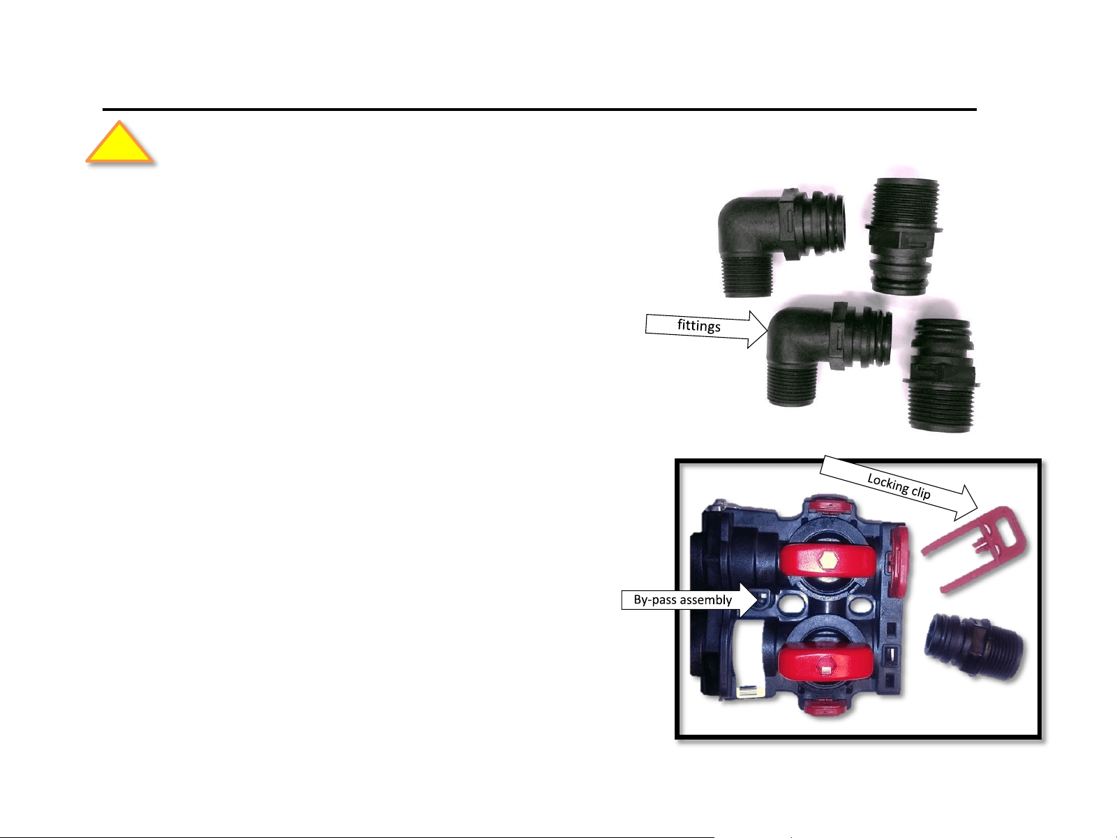
Important! - Be sure to lubricate the o-rings on
the quick connect fittings prior to installation.
3. Make final main water connections to the
valve, using quick connect fittings.
Included fitting options:
(2) 3/4 “ male threaded 90 quick connect fitting
(2) 1” male threaded straight quick connect fitting
a) Install fittings on the by-pass by removing
the red locking clips.
b) Return the red locking clips to secure the
fitting.
Plumbing Connections
Be sure to comply with all required plumbing codes.
Fig. 1
!
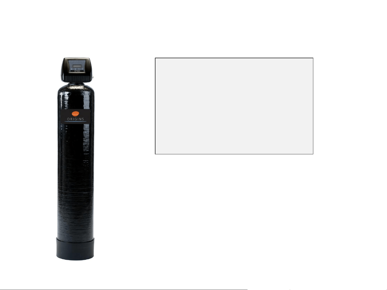
1850 Valve
(Metered for demand regeneration)
• By-pass valve is included and comes
with ¾” and 1” quick connect pipe
fittings
• Metered for demand regeneration
• Ideal for softeners, iron, sulfur,
carbon and sediment filters
• For tanks to 16” (softeners)
• For tanks to 10” (filters)
• Easy to program
• Operational data shown on LED,
including flow rate, last regeneration
date, gallons remaining and more
HF 200
Features
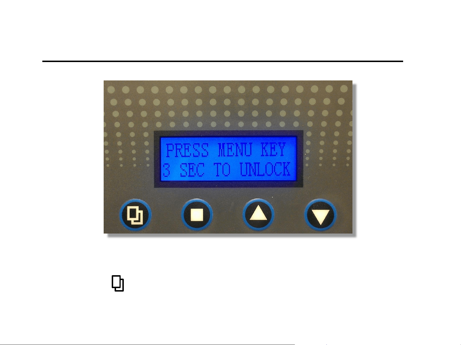
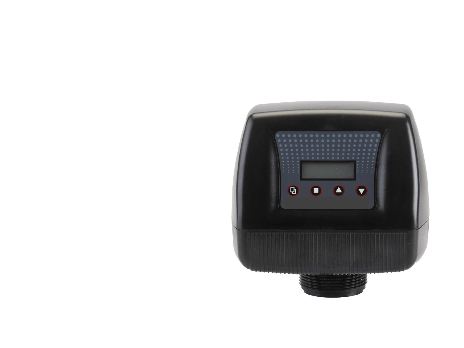
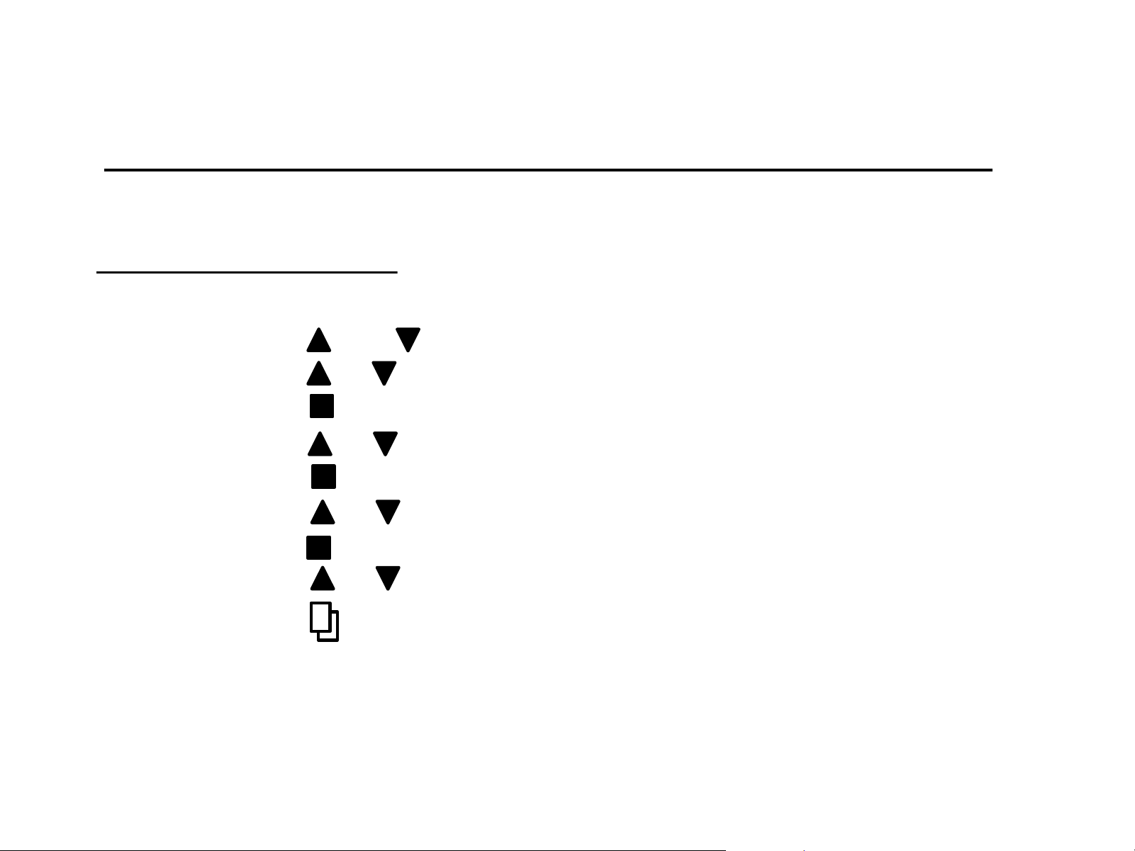
Valve Programming
Press and hold for 3 seconds to unlock the valve for programing.
FIRST - UNLOCK VALVE
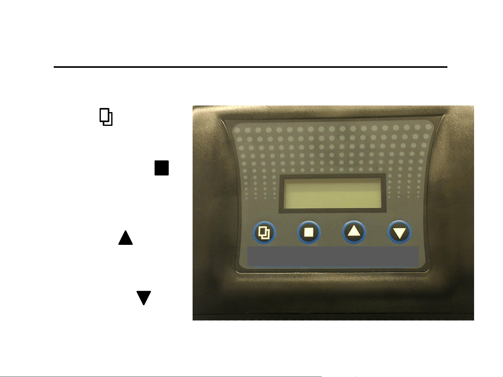
1) Menu Key
Press this key to enters or exit menu
Settings
Valve button programing control definitions
2) Set / Save Regen Key
Press this key to select a program
or to save a setting
3) Up arrow Key
Press these keys to go to the
previous menu
4) Down arrow Key
Press these keys to go to
the next menu
HF 200
Level-I Set up Parameters
(Required for initial set-up)
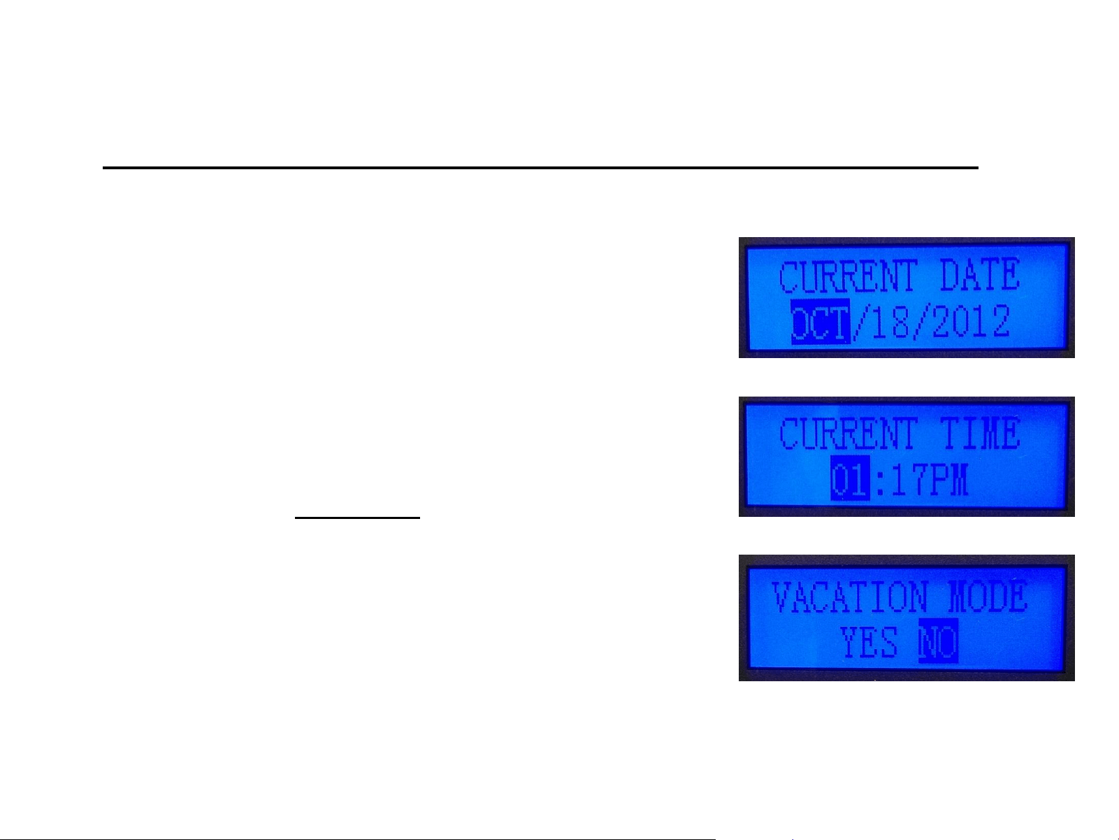
Level-1
Time – Enter the time of valve set up.
Date - Enter today’s date at time of valve set up.
Vacation Mode – Default is no, changing this setting
will change the valve operation to a
calendar cycle.
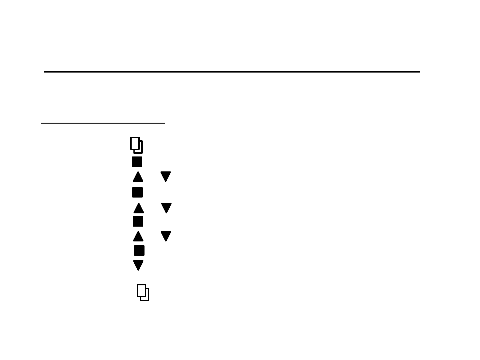
Time
1) Press * to enter menu (hour display will be highlighted)
2) Press to enter hour setting (must be flashing to edit)
3) Press or to adjust hour
4) Press to save and move to minute setting (flashing)
5) Press or to adjust minute
6) Press to save and move to AM/PM setting (flashing)
7) Press or to adjust AM/PM
8) Press to save and move to hour spot (not flashing)
9) Press to go to current date set up or to cycle through level I
settings (continue to set all level I setting)
10) Press * to exit menu and return to main screen
Making Adjustments – Level I
All programing is adjusted using the methods described in the programing method.
Setting level I programing
*Note: if valve is “locked” you will need to press and hold menu for 3 seconds. Valve will “beep” when
changing menus or parameters. Highlighted parameter must flash to be able to adjust setting.

Reasons to change Level-II setting (examples)
1) Initial start up configurations
2) Using tanks other than 9X48
3) Using Valve for Carbon or Iron Filter
4) Setting valve up for use in in Iron Filter
5) Adjusting any cycle or setting to enhance performance
Level-II Programming
(Settings have been pre-set at the factory)
These settings have been made at the factory and are held in memory. Level-II settings will
not be lost during a power outage. However, if adjustments are desired, follow the
directions below.
Level-II
• Language
• Valve operation
• Regen Mode
• Regen Time
• Capacity Calc.
• Resin Volume (FT3)
• Salt Settings (lbs./FT3)
• Refill Flow Rate (GPM)
• Unit Capacity (grains)
• Reserve Capacity
• Backwash (min)
• Brine/Rinse (min)
• Rapid Rinse (min)
• Refill (min)
Backwash
1) Press and together to enter menu (5 sec.)
2) Press or scroll to backwash setting
3) Press to enter menu (flashing)
4) Press or to adjust minutes (flashing)
5) Press to save setting and advance to tenths of minute
6) Press or to adjust tenths of minute for backwash
7) Press to save
8) Press or to move to another menu
9) Press to exit menu and return to main screen
Making Adjustments – Level II
All programing is adjusted using the same methods as for Level-I programming.
Setting level II programing
*Note: If the valve is “locked” you will need to press and hold menu for 3 seconds. Valve will “beep” when
changing menus or parameters. Highlighted parameter will flash when you are able to adjust setting.
Note: Valve must be in manual mode to adjust and save capacity and refill duration.
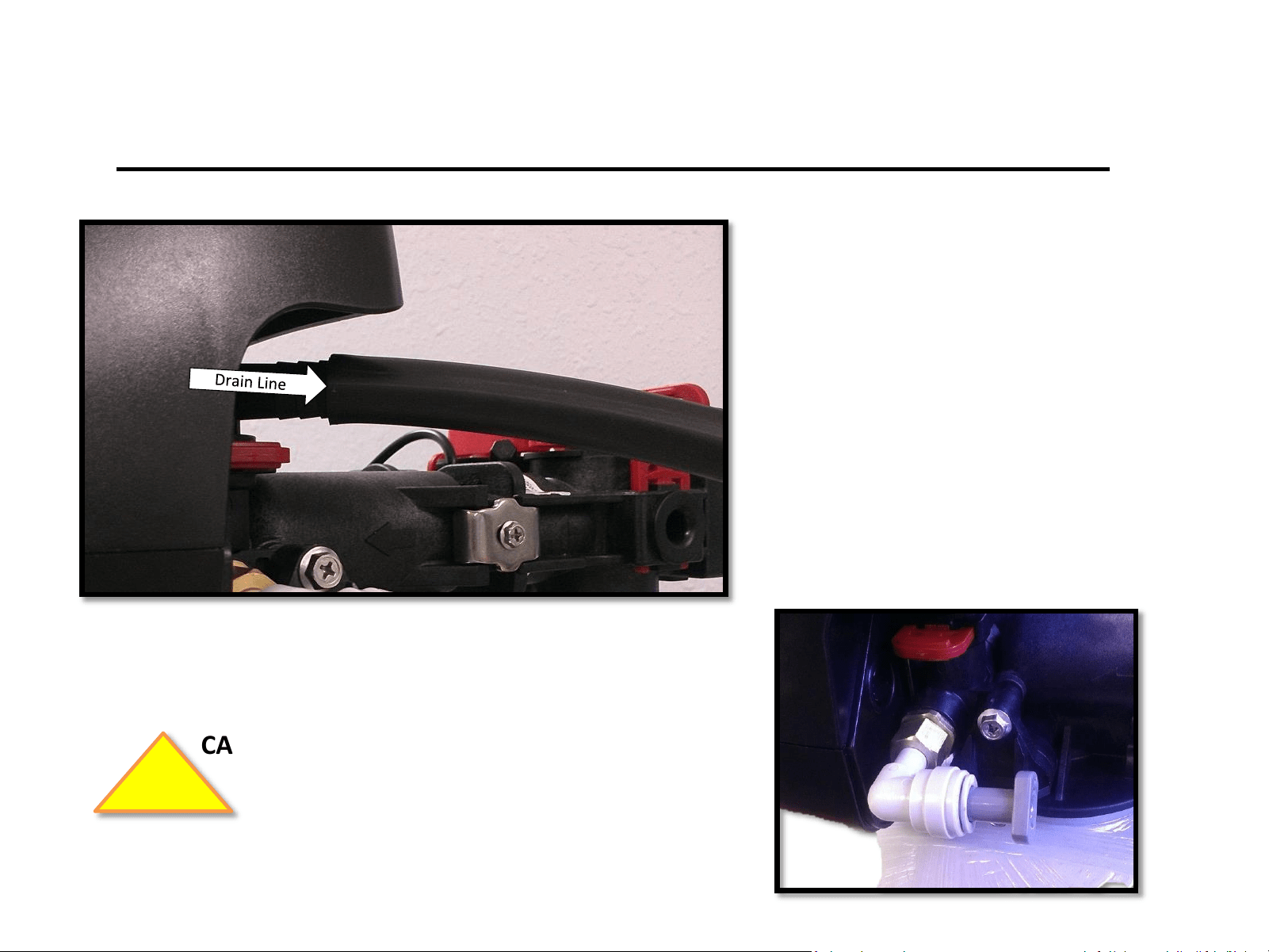
Connect Drain Line
Connect drain line
Slide the supplied drain line
tube over barbed drain line
connection fitting until
secured.
CAUTION: Inspect valve for “brine plug” installed at
the factory. (Plug is required to prevent
water leaking when valve advances)
!
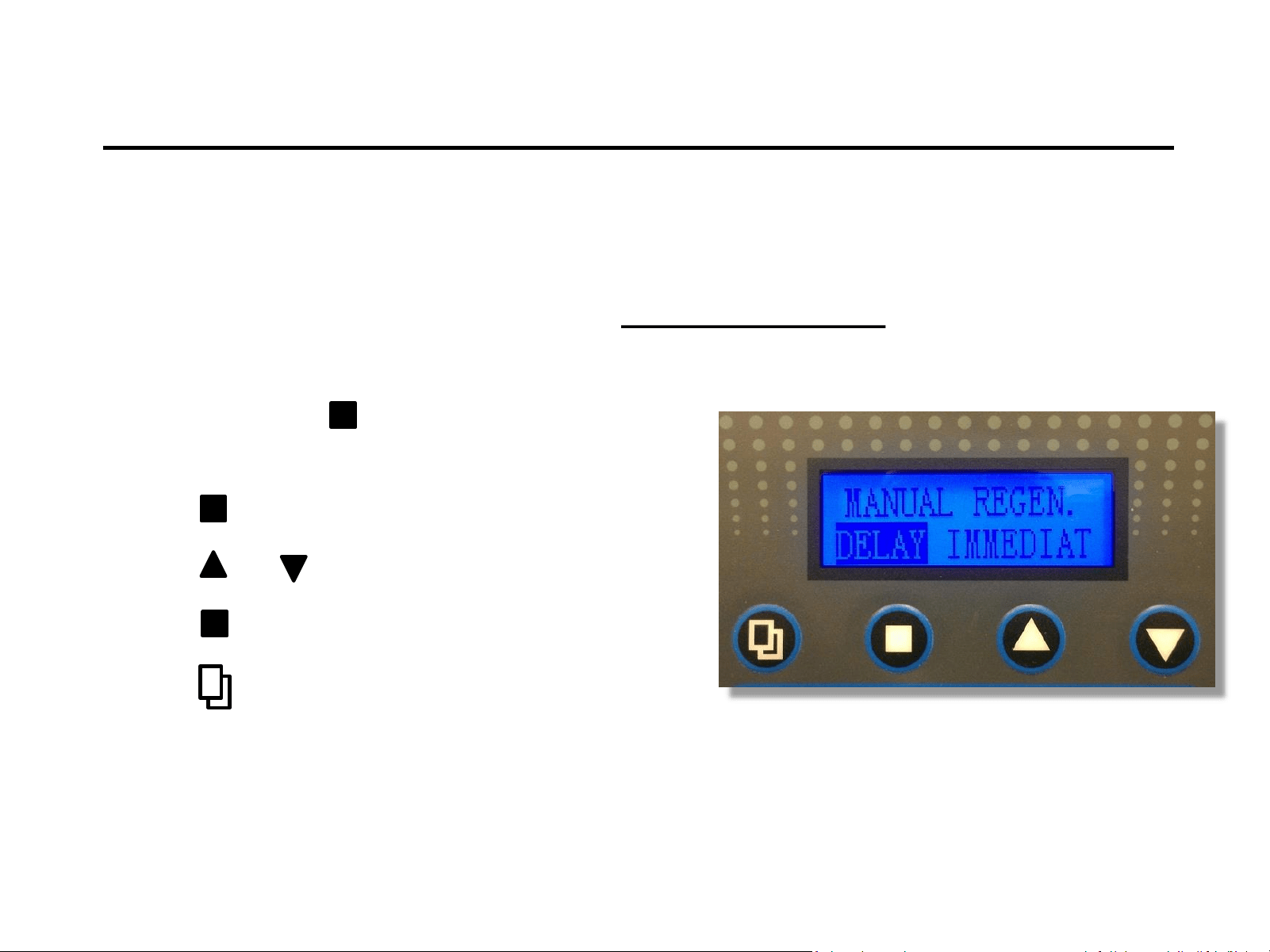
System Start Up
1) Press and hold to enter Manual Regen
Mode. (press for 3-5 seconds)
2) Press to enter edit mode (flashing)
3) Press or to select immediate (flashing)
4) Press to save
5) Press to show “Advancing to Backwash”
Note: Valve will reset backwash cycle to delay after manual regen. cycle has finished.
Notice:
For initial start-up, the Inlet and Outlet valves on the bypass
should be in the closed position.
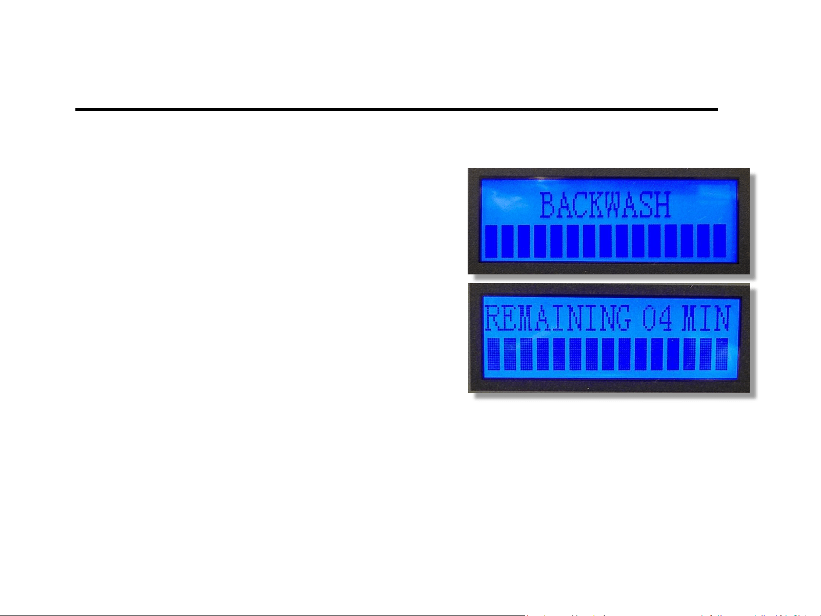
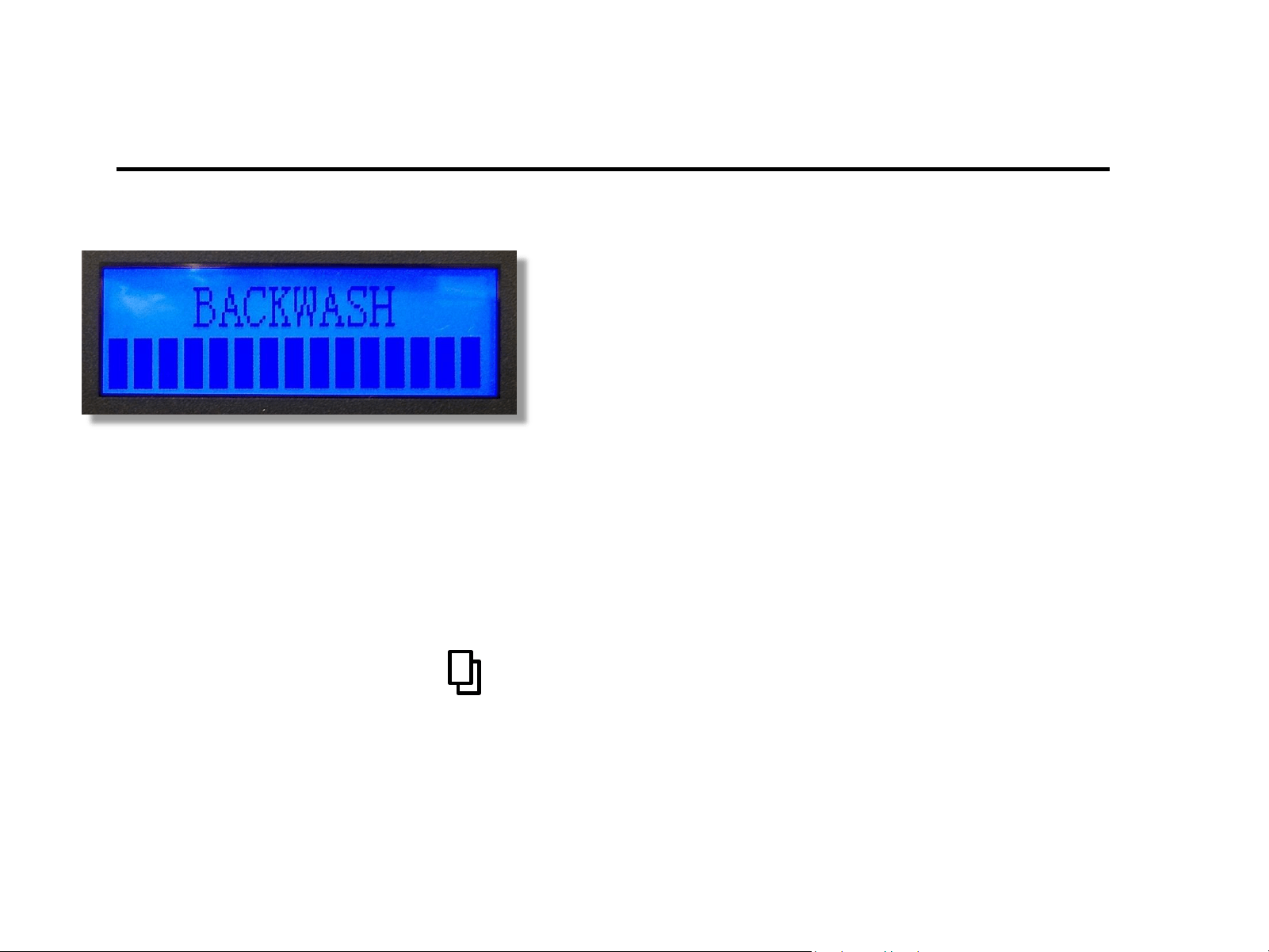
Start-Up In Backwash
1) Screen will now display
“Backwash” and flash
“Remaining XX min”
2) You will need to run
Backwash cycle until
drain line runs clear
NOTE: When advancing to another cycle, valve will show “advancing to”. Once the
valve is “in” a subsequent cycle, you may press any button to advance to
another cycle. Valve cannot be advanced while in the “advancing to” position.
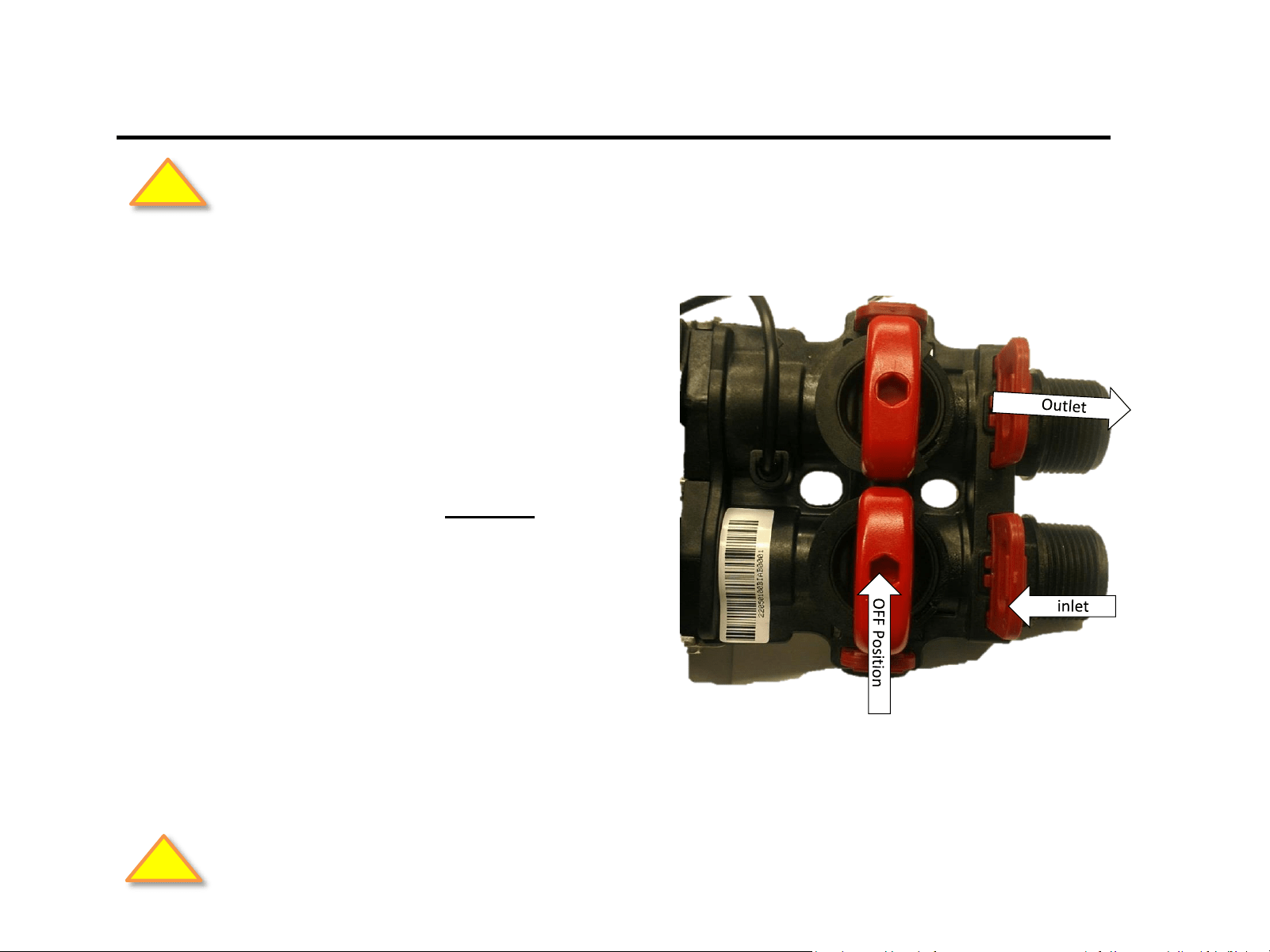
Fill the Mineral Tank
1) With bypass valves in the
“OFF” position turn on the
main water supply.
2) Open “Inlet” valve slowly ¼
turn clockwise to fill the media
tank. Continue to open inlet all
the way.
If the mineral tank was not filled, do so at this time following the directions below:
CAUTION: Allow time for glued connections to cure before proceeding.
!
CAUTION: Inspect all plumbing connections. Check for leaks and make repairs as needed.
!
NOTE: Watch to see if the backwash flow rate is proper – do not obstruct
drain line. This is particularly important for Iron and Sulfur filters.
REPEAT of the initial backwash cycle may be required should the backwash
discharge water does not run “clear” after unit has finished the first cycle.
NOTE: It’s common to run multiple backwash cycles with carbon and Iron
filters due to the amount of “fines” in the media.
System Start up
Leave the system in backwash for a minimum
of five to ten minutes until the water runs
clear. This will flush loose particles and
preservatives from the media.
Press to advance to the next cycle
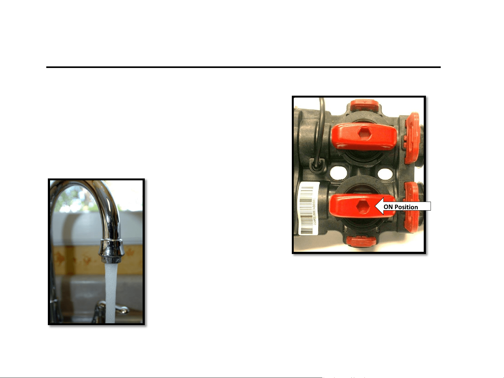
Ready for Service
1) Slowly open outlet to supply
water to the house.
2) Open faucet in the house to remove
debris and air flushing the system.
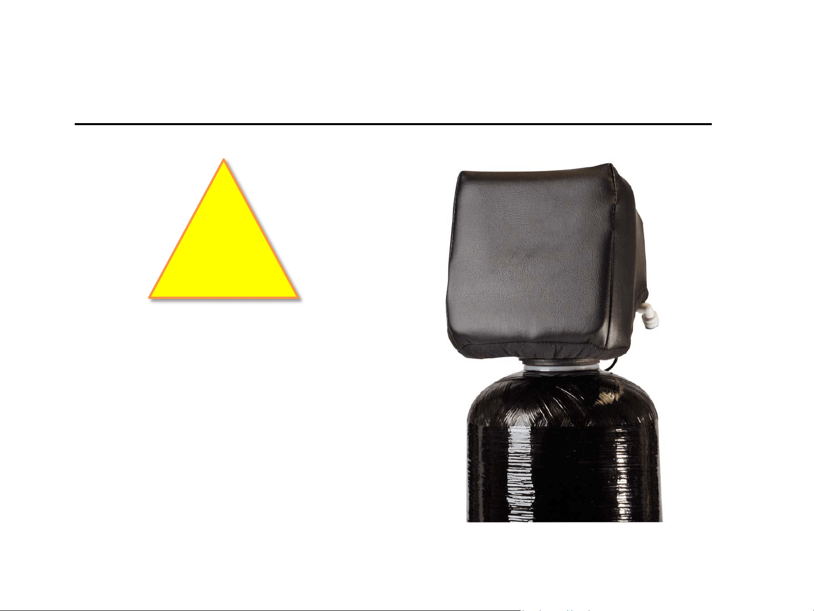
Weather Cover
(For outdoor installations)
WARNING
If the water treatment system is to be installed
outside, exposed to the weather and/or UV
Rays, it is necessary to install a weather cover
over the valve. The weather cover will protect
the valve from the damaging effects of UV
Rays on the LCD Screen and is required to
submit a warranty claim.
!