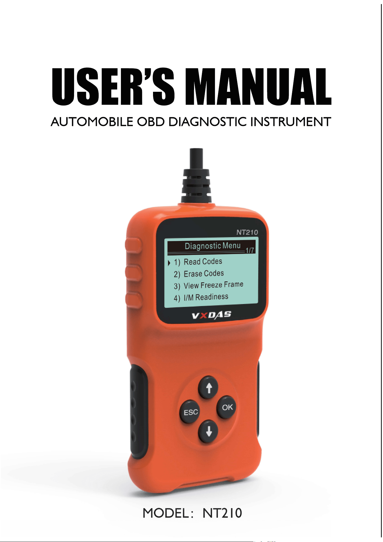
MODEL NT210
AUTOMOBILE OBD DIAGNOSTIC INSTRUMENT

Safety measures and warning
For preventing physical injuries, or causing
damage for the vehicles and decoder, please
read this operating manual before using this
instrument on the vehicle, and comply with the
following safety measures:
Detection shall be carried out in safe
environment.
Keep clothes, hair, hands, tools, test equipment
away from all motor heating components.
Operate the vehicle in a well-ventilated area:
waste gas is harmful to the human body.
Place a block plate in the front of the drive
wheel, make sure the vehicle is guarded during
operating the test.
Be more careful when operating near the
ignition wire and spark plug of ignition coil
distributor cover. These components will
generate the dangerous voltage when the
engine is running.
Place the gearbox in PARK (automatic gearbox)
or NEUTRAL (manual gearbox), and make sure
the parking brake is connected.
Put the fire extinguishers applied to petrol/
chemical electrical fire near it.
Do not connect or disconnect any test
equipment when ignition switch is opening or
engine is running.
Decoder operation
Keep decoder dry, clean, not adhere oil / water
or lubricants. Wipe the decoder by a clean with
the gentle cleaner if necessary.
Wear the eye protective device accorded with
ANSI standard.
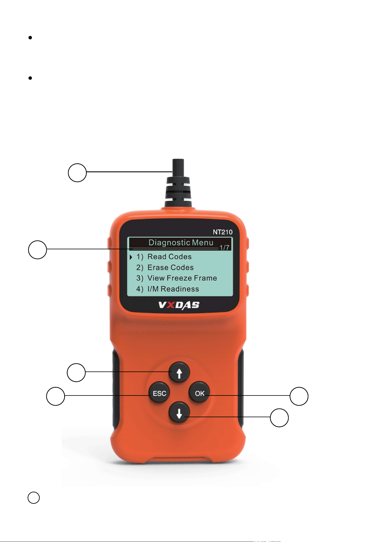
Tool description
Diagnostic joint - Connect the decoder to the
vehicle data link connector (DLC).
1
1
2
3
4 5
6

Specification
Display: Badit, 128 * 64 pixel display
Working temperature: 0~60 (32~140 )
Storage temperature: -20~70 (-4~158 )
Size: Length: 95.5 mm, width: 72.1 mm, height:
22.2mm
External power supply: Vehicle batteries supply
9.0 to 16.0V
LCD display - Display the detection result.
2
Up roll button - Roll the menu and submenu in
menu mode. When several dT are retrieved, it
will move up to the previous screen by the
current screen to obtain the other DTCS and
definitions.
3
Return button - Cancel the selection (or
operation) in the menu or return to the menu.
Long press for 3 seconds, it is also used to set
the unit.
4
Confirm button - confirm the selection (or
operation) in the menu. Applied to move down
to the next screen to get the other data.
5
Down roll button - Roll the menu and submenu
in menu mode. When several dT are retrieved, it
will move down to the next screen by the
current screen to obtain the other DTCS and
definitions.
6

Power supply of vehicle
Product Setup
Enter setting menu
Vehicle data link connector (DLC) supplies the
power to decoder. Open the decoder by the
following steps
Carry out the adjustment and setting for the
decoder as below:
1. Language: Select the required language.
2.Measurement unit: Set the measurement unit
as imperial or metric units.
3.Contrast adjustment: Adjust the contrast of
LCD display screen.
·The settings will be always same,until changing
as the current settings.
1.Take down DLC cover plate from the vehicle
Some vehicles have the plastic cover plate,
need to take down it before inserting OBD2
cable.
2.Insert OBD II wire to vehicle DLC.
The second start screen, press Up/Down button
enter the system setting menu. Adjust and set
by the following setting options.
Language setting
The digital “x/x”on the upper right corner of the
screen show the total numbers of items under
the menu and the serial number of the current
selected item.
English as default.
In the system setting menu, press Up/Down
button to select the language, and then press
Return/Confirm button.
Press Up/Down button to select the required
language, press Return/Confirm button to save
the selection, and return to the previous menu.
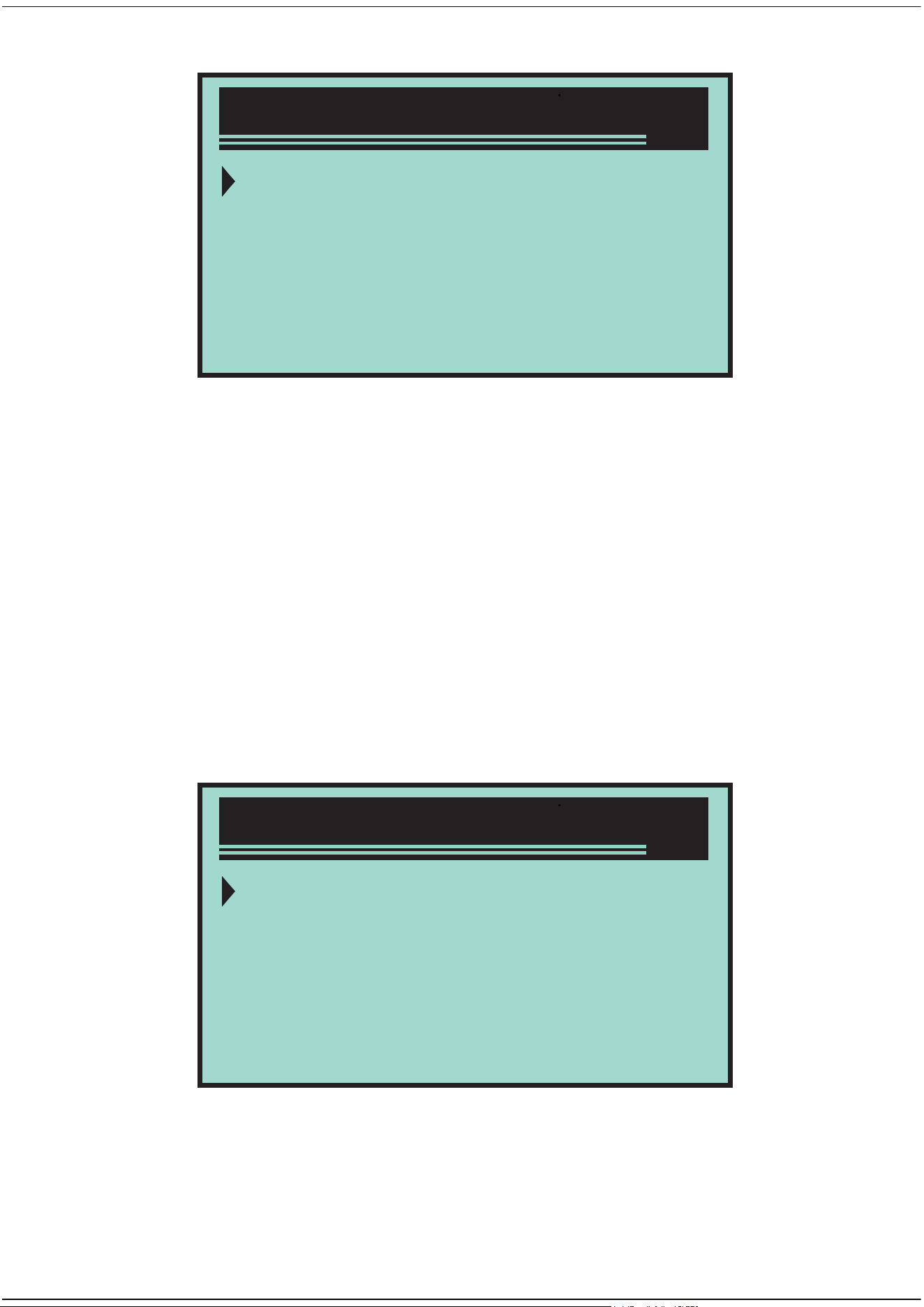
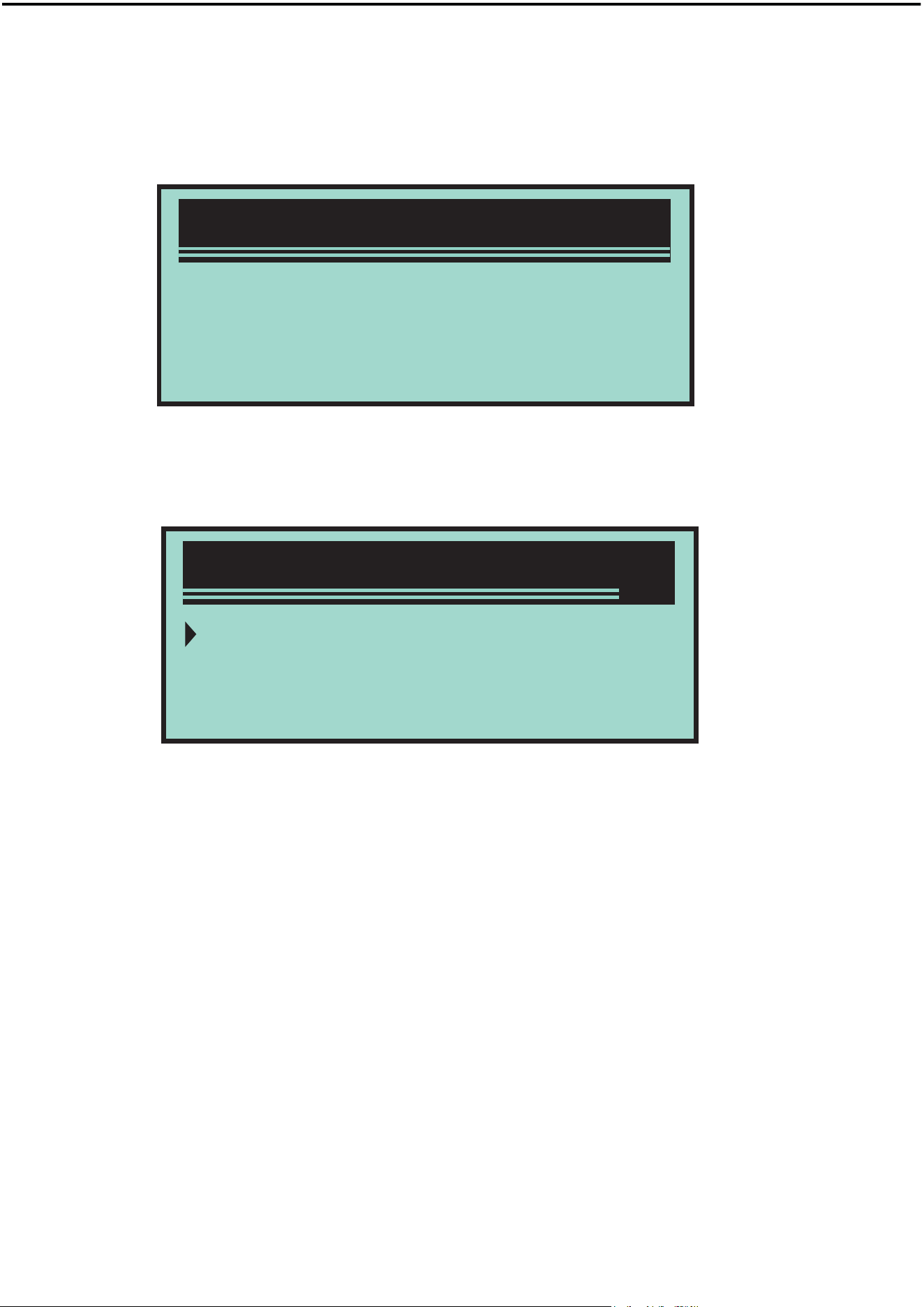
System Setup
1/4
1)Langyage
2)Unit of Measure
3)Contrast
4)Exit
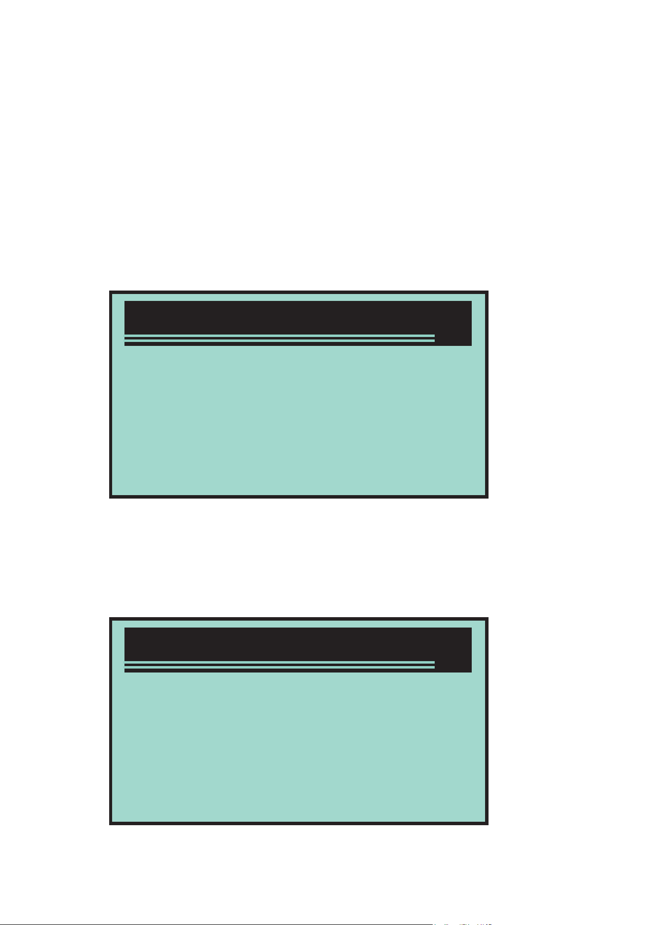
System Setup
1)Langyage
2)Unit of Measure
3)Contrast
4)Exit
1/4
Measurement unit
Measurement unit is metric unit by default
In the system setting menu, press Up/Down
button to select measurement unit, and then
press Return/Confirm button.
In the measurement unit menu, press Up/Down
button to select the required measurement unit.
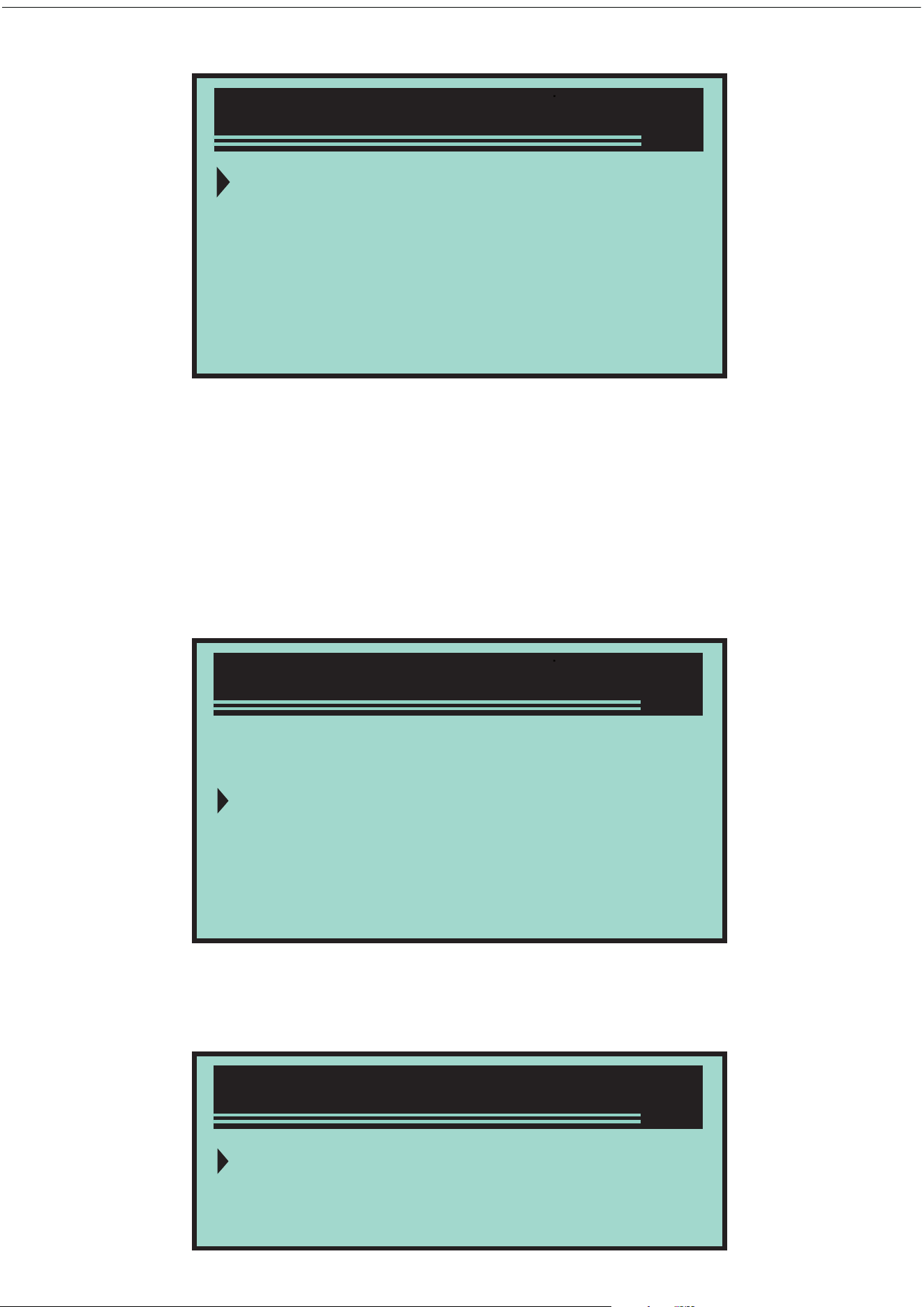
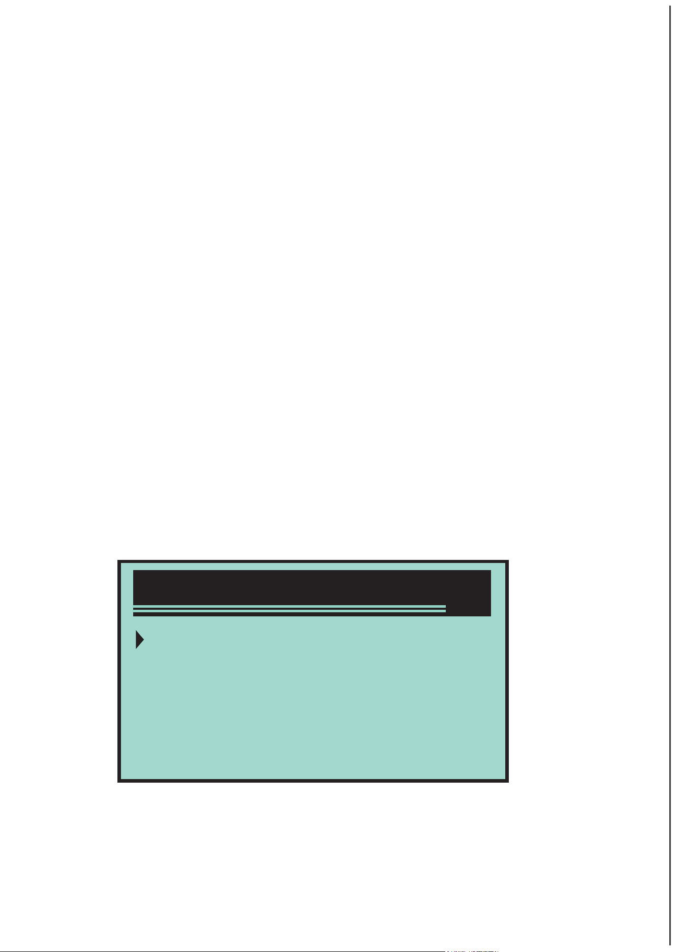
System Setup
1/4
1)Langyage
2)Unit of Measure
3)Contrast
4)Exit
1/2
English
Measure
Unit of Measure
Language
Deutsch
Dutch
English
Espanol
1/5
Contrast adjustment
Exit the system setting
Press Return/Confirm button to save the
selection, and return to the previous menu.
In the system setting menu, press Up/Down
button to select the contrast, and then press
Up/Down button.
In contrast menu, press Up/Down button to
adjust the contrast.
Press Return/Confirm button to save the
settings and return to the previous menu.
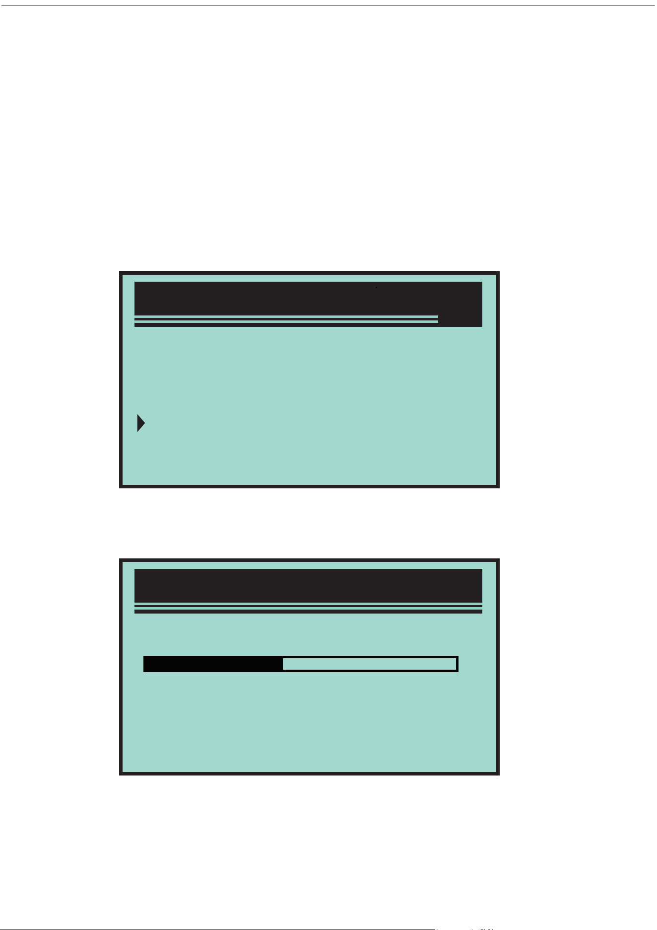
System Setup
1/4
1)Langyage
2)Unit of Measure
3)Contrast
4)Exit
System Setup
Contrast (35%)
Usetochange
>>
Application range of vehicle
Press Return/Confirm button to return to start
menu.
This OBD II / EOBD decoder is specially applied
to all the vehicles that accorded with OBD II
standard, including the vehicles for preparing
the next generation of protocols - controlling the
area network (have the capacity). All the
vehicles selling in USA as required by United
States Environmental Protection Agency, and
1996 newer (automobile) light trucks must be
accorded with OBD II standard. Including all the
domestic, Asian and European vehicles.
A small amount of 1994 and 1995 petrol vehicles
are accorded with OBD II standard. If need to
verify if 1994 or 1995 vehicles are accorded with
OBD II standard, please check the vehicle
emission control information (VECI) label, most
vehicles are stuck this label under the engine
jacket or near the radiator. If the vehicle is
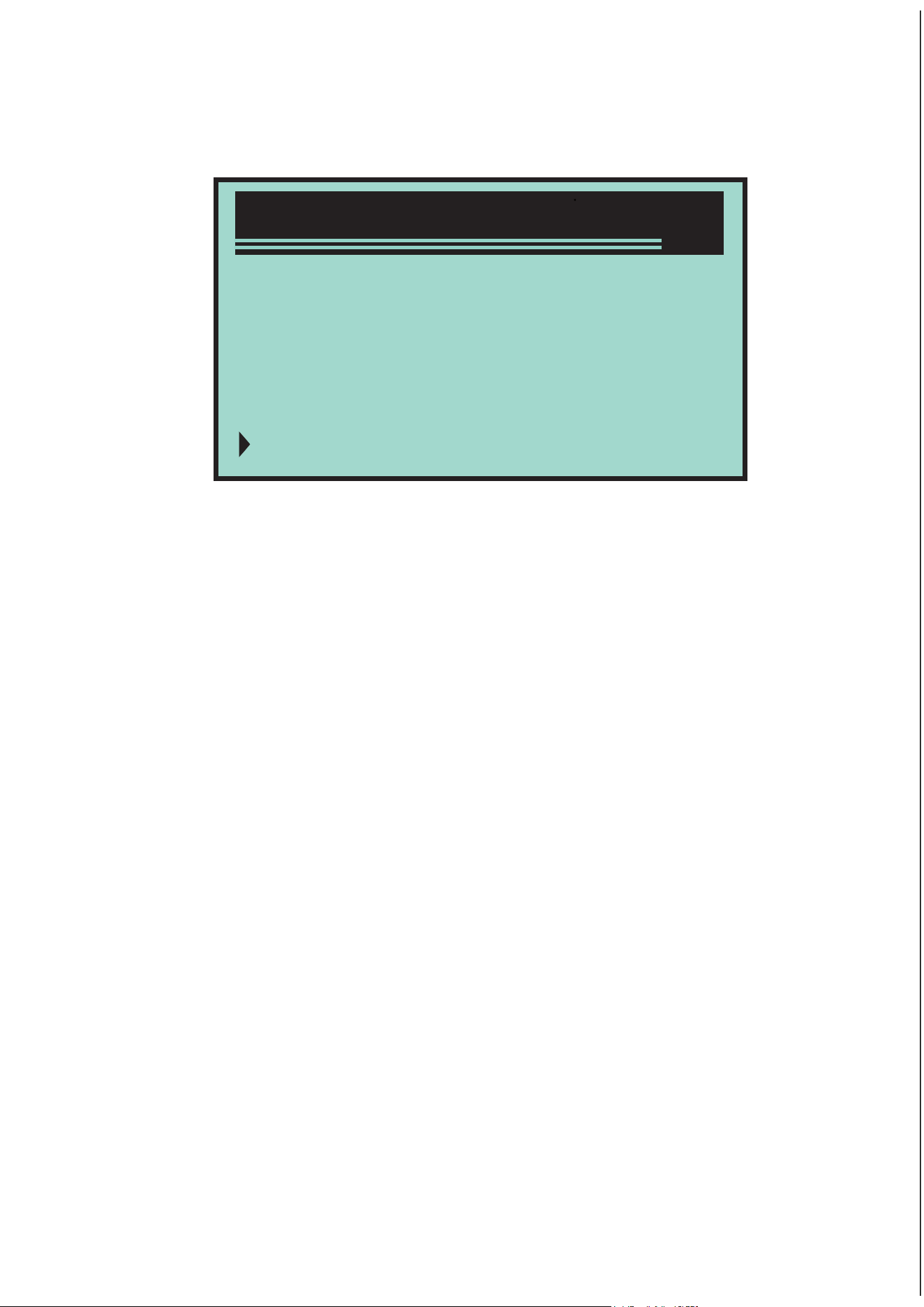
System Setup
1/4
1)Langyage
2)Unit of Measure
3)Contrast
4)Exit

OBD II diagnosis
accorded with OBD II standard, and then its
label is marked with “OBD II certification”. In
addition, the government laws and regulations
require all the vehicles that are accorded with
OBD II standard must have “General” 16 pin data
link connector (DLC).
If your vehicle is accorded with OBD II standard,
there must a 16 pin DLC (data link connector)
below the instrument panel, and a vehicle
emission control information label states the
vehicle is accorded with OBD II standard.
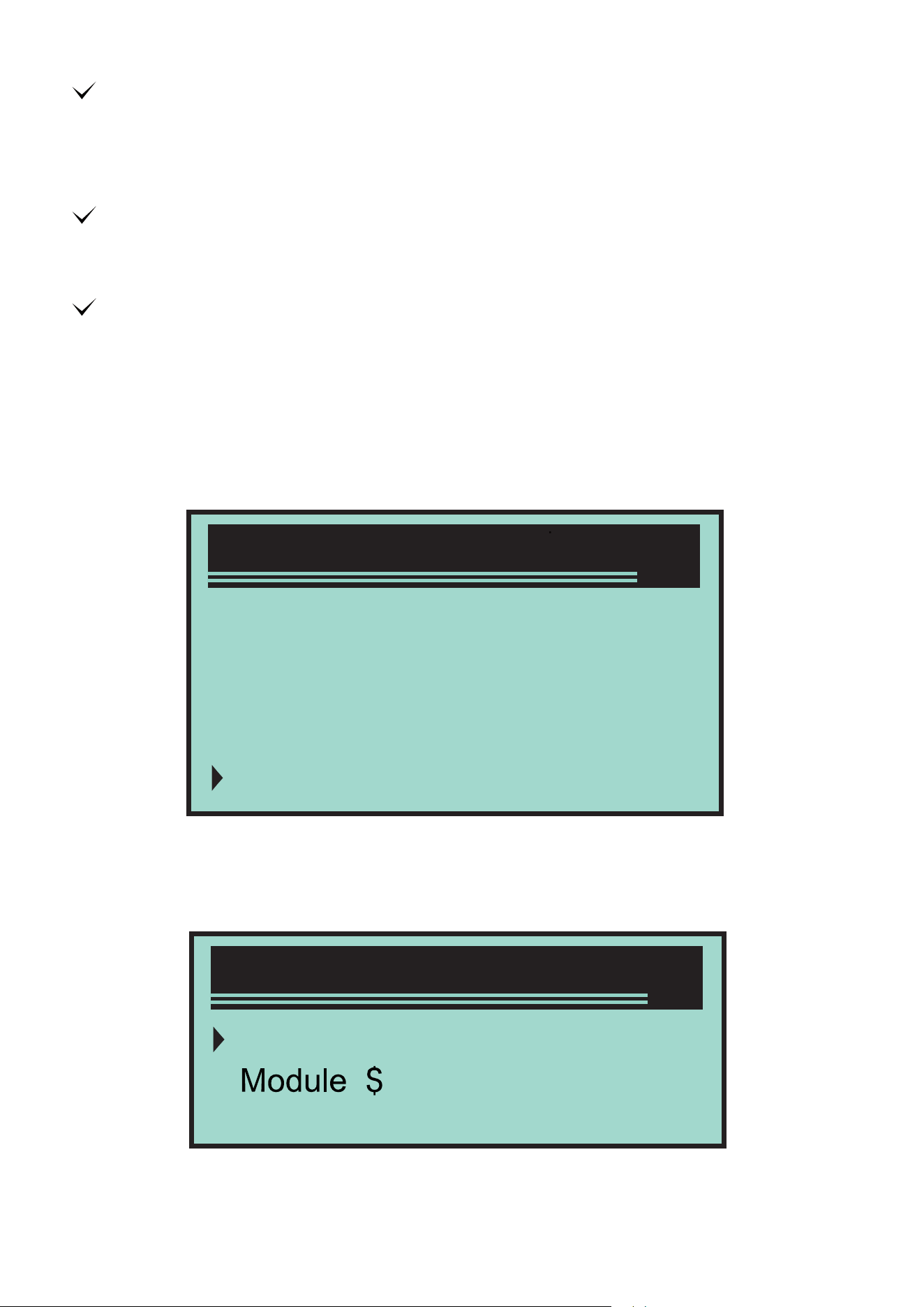
When diagnostic instrument detects multiple
vehicle control modules, the system will prompt
you to select the module that can retrieve the
data. Power assembly control module [PCM]
and gearbox control module [TCM] are the
commonly options.
Caution: Do not connect or disconnect any
test equipment when ignition switch is opening
or engine is running.
1.Turn o ignition switch.
2.Find the vehicle 16 pin data link connector
(DLC).
3.Insert OBD II wire to vehicle DLC.
4.Turn on ignition switch. Engine stops or runs.
5.Press Return/Confirm button to enter
diagnostic menu. A series of OBD2 protocol

information will be displayed on the display
screen, until the vehicle protocol is detected.
If decoder can not communicate with the
vehicle ECU (engine control unit), “Connection
error!” will be displayed on the display screen.
If “Connection error” information still appears,
and then it may be the communication between
decoder and vehicle has the problem. Please
contact the local dealer or the Customer Service
Department of the manufacturer for getting the
help.
After the system status (Diagnostic indicator
state, diagnostic code counting, monitor state) is
displayed, wait for several seconds or press any
key to display the diagnostic menu.
Confirm ignition switch is turned on;
System Status
1
4
3
1
Codes Found
MinitorsN/A
Minitors OK
MinitorsINC
Check if OBD II connector of decoder is
connected to vehicle DLC;
Confirm the vehicle is accorded with OBD2
standard;
Turn o ignition switch and wait for 10
seconds. Turn on ignition switch again, repeat
the steps in 5.
Read code
Press Up/Down button to select the read code
from diagnostic menu, and then press
Return/Confirm button.
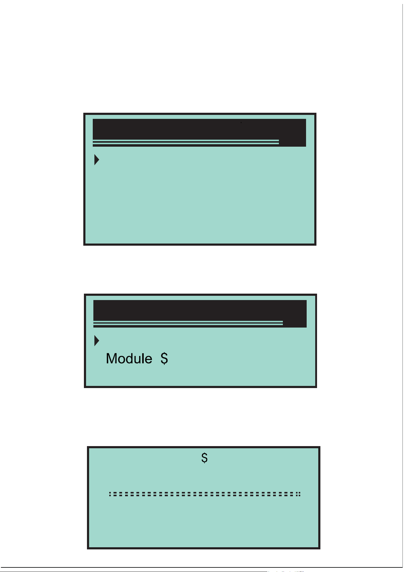
If multiple modules are detected, the system will
prompt you to select the module before testing.
Press Up/Down button to select a module, and
then press Return/Confirm button.
Read DTC and its definition on the screen
Diagnostic Menu
1/6
1)Read Codes
2)Erase Codes
3)View Freeze Frame
4)I/M Readiness
System Setup
Engine
A4
Exit
1/3
P0115
Ceneric
11 pd 1/6
EngineCoolantTemperature
Sensor 1 Circuit
Delete the code
Control module No., diagnostic code order, total
numbers of code to be detected and types of
code (general or specified by manufacturer,
storage or code to be processed) will be
displayed on the upper right corner of screen.
If find out multiple DTC, please press Up/Down
button by the requirements, until all codes are all
displayed.
If not detect the code, “Code is not stored in
module!” information is displayed on the screen.
If the retrieved DTC contains any code specified
by manufacturer or the enhanced codes, and
then “Controlled by manufacturer” is displayed
on the screen.
Press Return/Confirm button to return to the
previous menu.
Caution: Delete the diagnostic code of decoder
may not only delete the code on truck-mounted
computer,but also delete “Freeze Frame” data
and the enhanced data of the manufacturer. In
addition, I/M ready monitor status of all vehicle
P1324
Other
09 4/6
Manyfacturercontrol
monitors are reset as non-ready and non-finish
state. Do not delete the code before the
technicians check the system completely.
Implement this function by the key on (KOEO)
engine. Do not start the engine.
If decide to delete the diagnostic code, please
press Up/Down button to select “Delete the
code” from the Diagnostic menu, and then press
Return/Confirm button.
A warning message appears, and needs you to
confirm.
2/6
1)Read Codes
2)Erase Codes
3)View Freeze Frame
4)I/M Readiness
Erase Codes
Erasetroublecofes!
Areyousure?
NOYES
Diagnostic Menu

Read Freeze Frame data
If go on deleting the code, please press
Return/Confirm button to delete.
If the code is deleted successfully, and then
“Delete is finished !” information is displayed on
the screen.
If the code is not deleted successfully, and then
“Delete is failed. Rotate the key in the case of
engine is turned o !” is displayed on the screen.
Wait for several seconds or press any button to
return to Diagnostic menu.
If you want to go on deleting the code, press
Up/Down button to select, and press
Return/Confirm button. “Cancel the command”
information is appeared. Press any button or
wait for several seconds to return to Diagnostic
menu.
If need to read Freeze Frame, press Up/Down
button to select Freeze Frame diagnostic menu,
and then press Return/Confirm button.
3/6
1)Read Codes
2)Erase Codes
3)View Freeze Frame
4)I/M Readiness
Diagnostic Menu
If multiple modules are detected, the system will
prompt you to select the module before testing.
Press Up/Down button to select a module,and
then press Return/Confirm button.
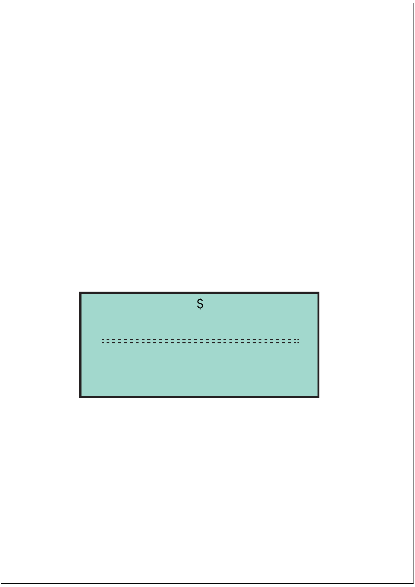
Wait for several seconds, until the decoder PID
mapping is verified.
If the retrieved information covers multiple
screens, and then need to press “Up/Down”
button, until all the data is displayed.
System Setup
Engine
A4
Exit
1/3
View Freeze Frame
ReadingPID.01
-Piease Wait-
View Freeze Frame
DTCFRZF
FUELSYSI
FUELSYS2
LASD_PCT(%)
P2770
OL
N/A
0.0
1/4

Retrieve I / M ready state
The digital “x/x”on the upper right corner of the
screen show the total Frame coverage of
retrieved data on the screen and the serial
number of the current displaying data. If no
available Freeze Frame data, “Freeze Frame is
not stored” information will be displayed on the
screen.
Press Return/Confirm to return to Diagnostic
menu
I/M ready function is used to check the
operating situation of vehicle emission system
that is accorded with OBD2 standard. This is a
very good function before checking if the
vehicle is accorded with the state emission plan.
Some newest vehicles models may support two
types of I/M ready test:
A. DTC has been deleted - Shows the display
status since DTC has been deleted.
B. This Drive Cycle - Shows the monitor status
since the current drive cycle has been started.
I/M ready result is “No”, it is not sure shows the
tested vehicle can not pass the state I/M check.
Some states permit one or multiple such
monitors are “Non-ready” passed the emission
check.
4/6
1)Read Codes
2)Erase Codes
3)View Freeze Frame
4)I/M Readiness
“Confirm” - Shows the diagnostic test for the
special monitor being checked has been
finished.
“INC” - Shows the diagnostic test for the special
monitor being checked has not been finished.
“Not applicable” - The vehicle doesn’t support
the monitor.
Press Up/Down button to select I/M ready from
Diagnostic menu, and then press
Return/Confirm button.
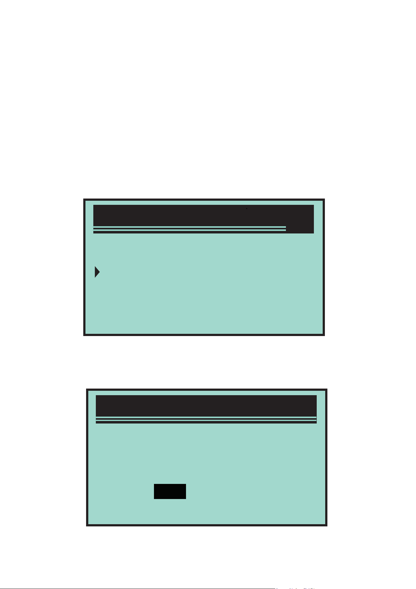
If multiple modules are detected, the system will
prompt you to select the module before testing.
Press Up/Down button to select a module, and
then press Return/Confirm button.
System Setup
Engine
A4
Exit
1/3
Diagnostic Menu
Wait for several seconds, until the decoder PID
mapping is verified.
If the vehicle supports two types of test. Two
types are displayed on the screen for selecting.
Press Up/Down button to read MIL light status
(“ON” or “OFF”) and the following monitors:
Press Up/Down button to read MIL light (“ON”
or “OFF”) and the status of the following
monitors:
· Misfire monitor-- Misfire monitor
· Fuel System Mon-- Fuel system monitor
· Component-- Comprehensive component
monitor
· EGR-- EGR system monitor
· Oxygen Sens Mon-- Oxygen sensor
monitor
I/M Readiness
SinceDTCsCleared
ThisDriveCycle
Exit
1/3
I/M Readiness
ReadingPID.01
-Piease Wait-
If the vehicle supports “This Drive Cycle” ready
test, the following information will be displayed
on the screen:
· Catalyst Mon-- Catalyst monitor
· EVAP System Mon-- Evaporation system
monitor
· Oxygen Sens htr -- Oxygen sensor heater
monitor
· Sec Air System-- Secondary air monitor
· Htd Catalyst-- Heating catalyst monitor
· A C Refrig Mon--A / C system monitor
SinceDTCCleared
MIL Status
Misfirs Monitor
FuelSystemMon
Comp.Component
OFF
OK
OK
OK
1/3
ThisDriveCycle
MIL Status
Misfirs Monitor
FuelSystemMon
Comp.Component
ON
OK
OK
OK
1/3
Read the vehicle information
Diagnostic Menu
5/6
5)VehicleInfo
6)Exit
The digital “x/x”on the upper right corner of the
screen show the total coverage of retrieved data
on the screen and the serial number of the
current displaying data.
Press Up/Down button to return to the previous
menu.
Vehicle information function can retrieve vehicle
identification number (VIN), calibration sign,
calibration verification number (CVN) and the
models above 2000 support the vehicle
performance tracking of mode 9.
In Diagnostic menu, press Up/Down button to
select the vehicle information. Press
Return/Confirm button.
Wait for several seconds or press
Return/Confirm button to go on.
If the vehicle doesn’t support this mode. “The
selected mode is not supported !” information is
displayed on the screen.
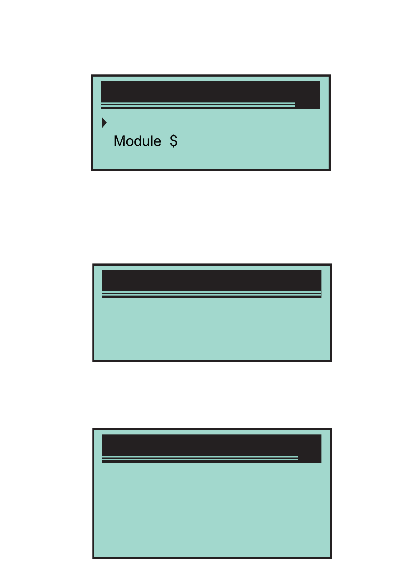
If multiple modules are detected, the system will
prompt you to select the module before testing.
Press Up/Down button to select a module, and
then press Return/Confirm button.
When decoder is reading the vehicle
information, please wait for several seconds.
ControlModule
Engine
A4
Exit
1/3
VehicleLnfo
Turn key on
Press[ENTER]tocon_
withengineoff!
VehicleLnfo
ReadingInfo...
-PleaseWait-

1/4
VehicleIDNumber
CalibrationID
Cal.Verif.Number
Exit
In vehicle information menu, press Up/Down
button to select the available items you want,
and then press Confirm button.
Read the retrieved vehicle information on the
screen.
Press Return/Confirm button to return to the
previous menu.
VehicleLnfo
VIN:
ZHGES16684H907944
VehicleIDNumber

Points for Attention
This product is incompatible with new energy
vehicles, hybrid vehicles and vehicles not under
the OBD2 protocol.
Disclaimer Conditions
We are committed to providing unparalleled
customer support to our customers before and
after sales. Below we oer our exemption for
this product:
If any of the following conditions are met, the
customer shall not enjoy the benefits covered
by this limited warranty:
a Products are damaged due to abnormal use,
abnormal conditions and improper storage,
such as exposure to humidity or dampness,
unauthorized modification, unauthorized
maintenance, misuse, negligence, abuse,
accident, modification, improper installation or
other non-malfunctioning behaviour , including
damage caused by transportation.
b Our company is not responsible for damage
to products caused by external causes (such as
collision with objects) or fire, flood, sand, dust,
storm, lightning, earthquake or weather
conditions, irresistible acts of natural disasters
or leakage of batteries, theft, fuse breaking,
incorrect use of any power source.

USER’S MANUAL
AUTOMOBILE OBD DIAGNOSTIC INSTRUMENT