SAVE THESE INSTRUCTIONS IN A LOCATION CLOSE TO YOUR
CABINET SO YOU CAN REFER TO THEM AT A LATER TIME.
IMPORTANT SAFETY INSTRUCTIONS
This portable lamp has a polarized plug (one blade is wider than the other) as a feature to reduce the risk
of electric shock. This plug will fit in a polarized outlet only one way. If the plug does not fit fully in the
outlet, reverse the plug. If it still does not fit, contact a qualified electrician. Never use with an extension
cord unless plug can be fully inserted. Do not alter the plug. Read entire installation procedure before you
begin.
INSTALLATION PROCEDURE - Suitable for under-cabinet mounting
Carefully plan out your installation prior to actually securing your fluorescent undercabinet fixture to the
mounting surface making sure that your 5 ft (1.52 m). line cord will reach the nearest electrical outlet.
1) Consult a local licensed electrician or electrical contractor if you are not sure about the installation.
2) DO NOT ATTEMPT TO INSTALL FIXTURE WHILE PLUGGED IN.
3) Select a suitable dry mounting location (for use indoors only). Make sure mounting surface is capable
of supporting the fixture.
4) Pre-drill holes in the mounting surface with a 1/16" (1.6mm) drill bit for softwoods and a 3/32"
(2.4mm) drill bit for hardwoods.
Vertical Mounting Position
5) Place the fixture in a location where you want it mounted. Make sure the switch will be
accessible when the fixture is mounted and that your 5 ft. (1.52 m) line cord will reach the
nearest electrical outlet. Mark the position of the fixture on one end, with a pencil. This will
be the outer most edge ofthe fixture. See Figure 1. Place the lug on the inside of the line
and affix with the screw provided, through the round hole, to the mounting surface.
6) Slide the fixture over the mounted lug until it stops. See Figure 2.
7) Place the other lug slightly inside the track at the opposite end of the fixture, so the outer
most round mounting hole is visible. See Figure 3
8) Using the second screw provided, affix the second lug to the mounting surface.
9) Slide the fixture back over the second lug so that both lugs are hidden completely from
view. See Figure 4. Proceed to Plug-in and Linking Instructions.
WARNINGS TO REDUCE THE RISK OF FIRE, ELECTRIC SHOCK
OR INJURY TO PERSONS:
WARNING
Risk of electric shock
- Do not use in wet locations.
- Use indoors only.
- Turn power off before servicing -- see
instructions.
- Use only insulated staples or plastic ties
to secure the cords.
- Route and secure the cords so that they
will not be pinched or damaged.
Risk of burn
- Allow bulb to cool before handling.
Bulb may shatter and cause injury
if broken
- Do not use excessive force when
installing bulb.
- Account for small parts and destroy
packing material, as these may be
hazardous to children.
Risk of Fire
- A maximum of 10 fixtures can be added
to or linked together in an existing circuit.
- Not intended for illumination of
aquariums.
- Not intended for recessed installation in
ceilings or soffits.
- Not intended for “Up-Light” applications
where fixture is mounted horizontal with
the lens facing up.
- Not intended for surface installation
inside or on top of built-in furnishings
such as kitchen cabinets, china cabinets,
or trophy cases.
- Do not conceal power supply cord or
linking cord inside a wall, ceiling, soffit,
kitchen cabinet, or similar permanent
structure.
- Do not run the power supply cord or
linking cord through holes in walls,
ceilings, or floors.
- Not intended for use above stoves, cook
tops, or sinks
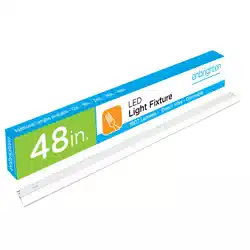
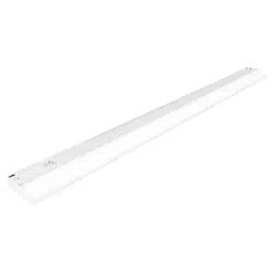
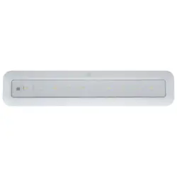
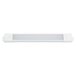
Linkable Fluorescent Undercabinet Fixture
12/8/10
10460
10167
10168
10169
GE is a trademark of the
General Electric Company
and is used under license to
Jasco Products Company LLC,
1o E. Memorial Rd.,
Oklahoma City, OK 73114.
www.jascoproducts.com.
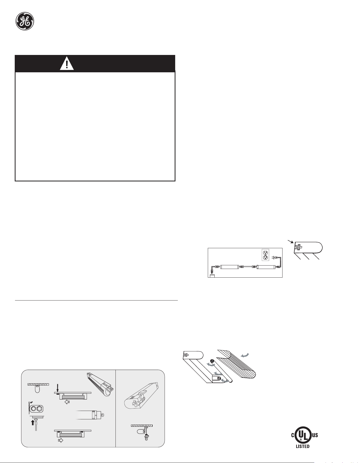
Fig. 8
Lens/Diffuser
(front edge)
Lente/Difusor
(borde frontal)
3 YEAR LIMITED FIXTURE WARRANTY
Jasco Products, warrants that the fixture will be
free of defects in material and workmanship for
three years from date of purchase. This warranty
does not apply to the bulb . This fixture warranty is
limited to repair or replacement at Jasco’s option.
Damage caused by modification, abuse , or misuse
is not covered. Jasco makes no other warranty
express or implied of merchantability or fitness for
a particular purpose. In no event shall Jasco be
liable for special, incidental or consequential damages. Some states do not allow limitations on how long an
implied warranty lasts and/or do not allow the exclusion of consequential damages, so the above
limitations may not apply to you. This warranty gives you specific legal rights and you may also have other
rights which vary based on your place of residence. To obtain repair or replacement information under the
terms of this warranty, return the fixture and proof of purchase along with owner's name and address,
postage prepaid to: Jasco Products Company LLC, 10 E. Memorial Rd. , Oklahoma City, OK 73114.
Horizontal Mounting Position
5) Place the fixture in a location where you want it mounted. Mark the position of the fixture
on one end with a pencil. This is a reference mark. This will be the outer most edge of the
fixture. Make sure the switch will be accessible when the fixture is mounted and that your 5
ft.(1.52 m) line cord will reach the nearest electrical outlet. Slide the first right angle lug into
the end of the fixture as far as it will go. See Figure 5. Using the first screw provided, affix
the first lug to the mounting surface. See Figure 5a.
6) Place the second right angle lug inside the track at the opposite end of the fixture. Slide
the lug in as far as it will go. Using the second screw provided, affix the second lug to the
mouning surface. Proceed to Plug-in and Linking Instructions.
PLUG-IN AND LINKING INSTRUCTIONS
1) Your line cord has a molded plug on one end, and a link connector at the other end. The link
connector plugs into your light fixture. The second cord provided is a linking cord with link
connectors on both ends. This is used to connect your light fixture to the next fixture in your
chain. Link adjacent fixture only. See Figure 7 below to see how the 2 pin and 3 pin plugs
are intended to be used.
2) Attach the quick connect power cord with the plug and three pin quick connector to the
fixture closest to the outlet. See Figure 6 and Figure 7.
3) Plug fixture into a 120VAC 60Hz outlet.
ATTACHING ADDITIONAL FIXTURES AT A LATER DATE
If you desire additional fixtures for your system after the initial installation, you may attach them as needed (sold
separately) by following these instructions. Keep in mind the maximum linking distance between fixtures is 18 in.
(45.7 cm) In addition, make sure not to exceed the 10 fixtures per line cord limit for your total installation.
CAUTION: DO NOT ATTEMPT TO ATTACH ADDITIONAL fixtures TO YOUR EXISTING
SYSTEM WITHOUT UNPLUGGING THE LINE CORD FROM THE ELECTRICAL OUTLET
OR DISCONNECTING THE ELECTRICITY AT THE ELECTRICAL POWER PANEL.
1) Install the additional light fixture following the installation procedures.
2) Once installed, attach the linking cord between the last light fixture (prevoiusly installed) and
the new one. See Figure 7 below to see how the 2 pin and 3 pin plugs are intended to be
used.
3) When adding a light fixture to an existing system of linked fixtures, the line cord (with the
power plug) is not needed. Only the first light fixture in the chain needs to be connected to
power with the line cord.
BULB REPLACEMENT INSTRUCTIONS
See the label on the fixture for replacement bulb type information.
Do not replace with any other wattage of fluorescent bulb.
1) Turn the fixture off and allow bulb to cool before handling.
2) Remove the lens/diffuser by lightly pulling the front edge while pulling downwards. The lens/diffuser
should pop out easily. See Figure 8.
3) Remove the bulb by grasping the ends of the bulb and rotating until the bulb becomes loose. Pull
straight out from the lamp holder. Be careful not to drop the bulb. See Figure 8.
4) Grasp the replacement bulb in the same manner and reinsert into the lamp socket, and turn tube until
it is securely held in place. Do not use excessive force when installing bulb.
5) Reinsert lens/diffuser.
Horizontal MountVertical Mount
Pencil Mark
Fig. 2
Fig. 4
Fig. 3
Fig. 1
Lug
Fig. 5
Fig. 5a
Quick Connect
ConexiónRápida
2 Pin 3 Pin 3 Pin2 Pin
3 Pin
Link Fixtures Up to 18” (45.7 cm) Apart
ELECTRICAL CORD CAN BE ROUTED AROUND
CORNERS TO SUIT THE INSTALLATION
Fig. 7
Fig. 6