

25A PLASMA CUTTER INVERTER
MODEL NO: PP25E
Thank you for purchasing a Sealey product. Manufactured to a high standard, this product will, if used according to these instructions,
and properly maintained, give you years of trouble free performance.
IMPORTANT: PLEASE READ THESE INSTRUCTIONS CAREFULLY. NOTE THE SAFE OPERATIONAL REQUIREMENTS, WARNINGS &
CAUTIONS. USE THE PRODUCT CORRECTLY AND WITH CARE FOR THE PURPOSE FOR WHICH IT IS INTENDED. FAILURE TO DO
SO MAY CAUSE DAMAGE AND/OR PERSONAL INJURY AND WILL INVALIDATE THE WARRANTY. KEEP THESE INSTRUCTIONS SAFE
FOR FUTURE USE.
1. SAFETY
1.1. ELECTRICAL SAFETY
WARNING! It is the user’s responsibility to check the following:
Check all electrical equipment and appliances to ensure that they are safe before using. Inspect power supply leads, plugs and
all electrical connections for wear and damage. Sealey recommend that an RCD (Residual Current Device) is used with all electrical
products. If the Plasma cutter is used in the course of business duties, it must be maintained in a safe condition and routinely PAT
(Portable Appliance Test) tested.
Electrical safety information, it is important that the following information is read and understood.
9 Ensure that the insulation on all cables and on the appliance is safe before connecting it to the power supply, regularly inspect power
supply cables and plugs for wear or damage and check all connections to ensure that they are secure.
9 Ensure that the voltage rating on the appliance suits the power supply to be used and that the correct plug is tted, with the correct
rated supply.
WARNING! The electrical installation of the plasma cutting unit must only be carried out by a qualied electrician.
8 DO NOT pull or carry the appliance by the power cable.
8 DO NOT pull the plug from the socket by the cable.
8 DO NOT use worn or damaged cables, plugs or connectors. Ensure that any faulty item is repaired or replaced immediately by a
qualied electrician.
1.2. GENERAL SAFETY
WARNING! If using a generator to power the inverter. the generator must be self regulating and stable with regard to voltage,waveform
and frequency. The output must be greater than the power consumption of the inverter. If any of these requirements are not met the
electronics within the inverter may be aected.
WARNING! The use of an unregulated generator may be dangerous and will invalidate the warranty.
WARNING! The inverter may produce voltage surges in the mains supply which can damage other sensitive equipment
(e.g. computers). It is recommended that the inverter is connected to a power supply that does not feed any sensitive equipment.
▲ DANGER! Direct contact with the plasma inverter circuit or torch is dangerous. You MUST unplug the inverter from the mains power
supply, before connecting or disconnecting cables or performing maintenance or service.
9 Keep the plasma inverter, cables and torch in good condition. Take immediate action to repair or replace damaged parts.
9 Use recommended parts and accessories only. Unapproved parts may be dangerous and will invalidate the warranty.
9 Only use the cutting torch provided and ensure that any replacement is of the same type.
9 Use the plasma inverter in a suitable work area. Ensure that the area has adequate ventilation as cutting fumes are harmful.
For enclosed areas we recommend the use of an air and smoke extraction system. If you are not able to provide adequate
extraction and/or ventilation, wear a respirator suitable for protection against toxic fumes, smoke and gases.
9 Ensure that there are no obstructions to the flow of clean cool air and ensure that there are no conductive dusts, corrosive vapours
or humidity which could enter the unit and cause serious damage.
WARNING Use a welding head shield to protect your eyes and avoid exposing skin to the ultraviolet rays given off by the electric
arc. Always wear protective clothing, insulating gloves and shoes. Keep all protective items clean and undamaged.
9 Wear correct fitting protective clothing, remove watches, rings and other loose jewellery and contain long hair.
9 Stand correctly, keeping a good footing and balance and ensure that the floor is not slippery. Wear non-slip shoes.
9 Ensure that the work piece is correctly secured before cutting.
9 Avoid unintentional contact with the work piece. Accidental or uncontrolled switching on of the torch may be dangerous and will wear the
nozzle.
9 Keep unauthorised persons away from the work area. Any persons working within the area must wear the same protective items as
the operator.
8 DO NOT use cables and torch if the insulation is worn or connections are loose.
8 DO NOT attempt to fit any unauthorised torch or other component to the plasma cutting unit.
8 DO NOT cut surfaces that are painted, galvanic coated, oily or greasy.
8 DO NOT use cables over 10m in length.
8 DO NOT connect the return cable to any structure which is not part of the work piece (other than a metal work bench supporting the
work piece).
▲ DANGER! DO NOT cut near flammable materials - solids, liquids, or gases. Remove all flammable materials such as waste rags etc.
PP25E Issue 3 28/08/24
Original Language Version
© Jack Sealey Limited
Refer to
instruction
manual
Fire
hazard
Arc rays
wear protective
eye protection
Electric shock
hazard
Fumes/gases
use in ventilated
area
Hot surfaces
wear protective
gloves
Magnetic fields
produced
Wear ear
protection

8 DO NOT cut containers or pipes which have held flammable materials - gases, liquids or solids. DO NOT cut materials that have
been cleaned with chlorinated solvents (or near such solvents) as vapours from the arc action may produce toxic gases.
8 DO NOT operate the inverter while under the influence of drugs, alcohol or intoxicating medication, or if tired.
8 DO NOT use the plasma inverter for a task it is not designed to perform.
8 DO NOT operate the plasma inverter if any parts are damaged or missing as this may cause failure and/or personal injury.
8 DO NOT strain or bend the cables, protect them from sharp or abrasive items and DO NOT stand on them.
9 Protect cables from heat. Long lengths of slack must be gathered and neatly coiled. DO NOT place cables where they will endanger
others.
8 DO NOT hold unsecured work piece in your hand.
8 DO NOT get the plasma inverter wet or use in damp or wet locations or areas where there is condensation.
8 DO NOT touch the work piece close to the cut as it will be very hot. Allow to cool. The cut edge of the work piece will also be very
sharp.
8 DO NOT touch the torch immediately after use. Allow the torch to cool.
9 When not in use store the unit in a safe, dry, childproof area.
WARNING! Before starting cutting, please carefully read the safety instructions, understand the hazards generated during welding,
and carry out corresponding inspections and protections. Some hazards may be fatal.
1.3. BEFORE CUTTING WORK
1.3.1. Environment Check
9 Use in a dry, low dust environments. Large amounts of dust may cause damage to the machine or endanger personal safety.
9 Work in a well ventilated area. Cutting may cause smoke and toxic gases which are harmful to human health.
8 DO NOT use the machine in rainy/snowy weather.
8 DO NOT use to thaw pipes.
8 DO NOT use near ammable or explosive environments.
1.3.2. Machine Check
9 Ensure power supply voltage is correct. If voltage is too high, it may damage the machine. Too low, and the machine may not start.
9 Check the power cord to ensure good contact. Loose connections may cause ignition. Exposed wires may pose a risk of electric shock.
9 Ensure earth wire is properly connected to reduce likelihood of electric shock.
9 Check output polarity is connected correctly.
1.3.3. Personnel Attention
9 The user must be experienced and trained to use welding machine.
9 The user should wear appropriate PPE such as protective clothing, helmet, ear and eye protection.
8 DO NOT disassemble the machine and do not work while the machine is being disassembled.
1.4. DURING CUTTING WORK
1.4.1. Toxic gas
9 Wear a mask when welding or cutting. During welding or cutting, toxic gases or suspended particles may be generated. Although you are
in a well ventilated environment and inhale only a small amount of harmful substances, long-term inhalation still poses great harm.
1.4.2. Noise Hazards
9 Wear ear protectors during welding. In MIG welding and plasma cutting, significant noise may be generated.
CAUTION: long term exposure to noisy environments may lead to hearing loss.
1.4.3. High Frequency Hazards
WARNING! If there are people around who are using pacemakers, please use the cutting machine with caution. Cutting machines have
high-frequency function, which may cause interference to some instruments.
1.4.4. Strong Light Hazards
9 Wear a welding helmet. The cutting process is accompanied by strong light, which may cause loss of your vision.
9 Strong light may cause dizziness. If working at height, there will be hazards. Ensure that you have taken appropriate protective measures.
1.4.5. Splash hazards
9 Wear protective clothing. Spatter generated during cutting is very hot and may cause burns to the human body.
WARNING! DO NOT work near ammable and explosive substances. Spatter may cause re or explosion.
1.4.6. Other Precautions
WARNING! The no-load voltage of the machine is high, and physical contact may be life-threatening. Be careful not to touch the outlet
of the machine directly.
8 DO NOT leave the machine while it is in working condition. If you stop working halfway, please make sure that the machine is turned
o, otherwise there may be an electric shock hazard.
8 DO NOT use long extension cables when welding. If unavoidable, ensure the cable diameter is appropriate.
8 DO NOT touch any part of the workpiece and welding equipment whilst working.
1.5. AFTER CUTTING WORK
1.5.1. High Temperature Attention
8 DO NOT touch the workpiece directly until it has cooled down.
9 The welding torch or welding rod that has just been welded has a high temperature and should be disposed of properly. DO NOT place
on ammable objects or items with a low melting point.
1.5.2. Tidy Up
9 After the work is completed, the machine should be turned off immediately.
9 After the machine is fully cooled down, start tidying up the equipment. Cut off the power and gas first.
1.5.3. Safekeeping
9 Store the machine in a dry, low-dust place.
9 Store the machine on a flat surface, not on a slope.
9 Protect cables from damage.
8 DO NOT place the machine in an environment prone to electric shock.
Original Language Version
© Jack Sealey Limited
PP25E Issue 3 28/08/24
2. INTRODUCTION
Inverter power supply fitted with plasma cutter control circuitry. Ideal for cutting steel, stainless steel, aluminium and brass off a 13A
Supply. Lightweight unit fitted with a carry handle makes it ideal for the mobile technician as well as being convenient to move around the
workshop or garage. Features air pressure regulator and variable amp control. Supplied with a 2.5m plasma torch, 2m earth cable, 2m
power cable. Maximum cutting thickness of 8mm.
3. SPECIFICATION
MODEL NO: PP25E
Fuse Rating: 13A
Power Supply Cable Length: 2m
Power Output: 15-25A
Duty Cycle: 30% - 25A
60% - 20A
100% - 15A
Max Cutting Thickness: 8mm
Air Requirements: 130 L/min
Working Pressure: 43.5psi
Supply: 230V
Absorbed Power: 4.6kVA
Insulation: F
IP Rating: IP21S
Weight: 5.9kg
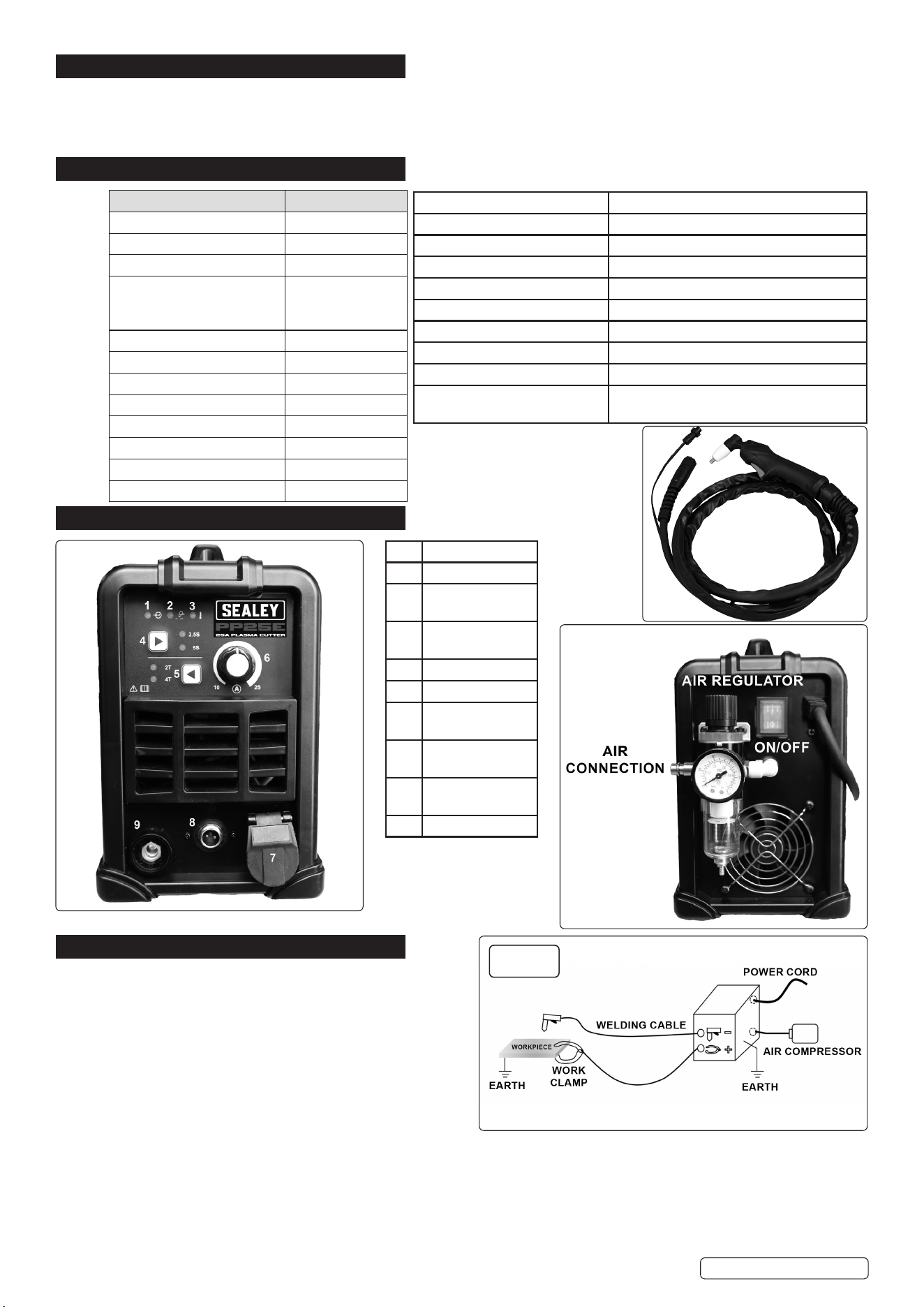
4. FEATURES
5. INSTALLATION FIG.1
5.1. Refer to fig.1 for correct set-up.
NOTE: incorrect polarity can damage the cutting tools and
lead to poor results: Workpiece polarity: +, Torch polarity: -
5.2. Ensure the machine is turned OFF.
5.3. Connect air supply.
NOTE: plasma cutting uses compressed air (0.4 to 0.6Mpa).
5.4. Check the power cable is good and the input voltage is correct.
5.5. Connect to mains supply.
5.6. If necessary, select the appropriate gas and connect the gas.
5.7. Connect earth clamp.
5.8. Connect the welding or cutting torch according to polarity.
5.9. Turn on, select the correct mode on the panel, and adjust the appropriate parameters. Before starting, ensure that no short circuit is
formed between the torch and the workpiece.
5.10. Only use on a stable horizontal surface at no more than 10° inclination.
Original Language Version
© Jack Sealey Limited
No. Description
1 Input voltage
2 Cutting in
progress
3 Temperature
Indication
4 Post gas selection
5 2T/4T
6 Current
adjustment
7 Cutting torch
connector
8 2 pin power
supply for torch
9 Earth connection
Insulation Class IP21S
Pollution Degree 3
Eciency of the product 85.1%
Torch type for plasma cutting HF
Air Pressure 3Bar
Flow Rate 130L/min
Type of plasma gas Air
Duty Cycle 30% (40°C)
EMC Classication Class A
Product’s Static Characteristics ±4kV Contact Discharge, ±8kV Air
Discharge
fig.1
PP25E Issue 3 28/08/24
6. OPERATION
6.1. SHORT CIRCUIT PROTECTION
When a short circuit is detected, the machine interrupts the output current to avoid remaining in a state of continuous high current.
Sometimes, a minimum output current may still persist; the user should therefore avoid causing short circuits between the electrode and
the workpiece as much as possible, and maintain a safe distance. Especially when using alkaline electrodes. In case of short circuit, it is
important to quickly remove the short circuit condition.
6.2. THERMAL PROTECTION (Features no.3)
6.2.1. After the light (Features no.3) illuminates, operation recovery time depends on how long it takes for the internal components to cool to
55°C. As ambient temperature changes, the recovery time may also vary. Recovery time is around 3 minutes.
6.3. 2T/4T
2T: Press the torch button to start the machine, it will immediately start working. Release the torch button to stop the machine.
4T: First Press: By pressing the torch button the first time, the machine is set to the initial current. First Release: By releasing the button,
the machine switches to the working current, used for the main phase of welding or cutting. Second Press: Pressing the button again, the
machine switches to the end current. Second Release: Releasing the button a second time, the machine stops operating.
6.4. POST GAS
When the button of cutting torch is released, the air continues to come out of the torch to allow the torch and workpiece to cool down and
to avoid unwanted chemical reaction. DO NOT disconnect from mains supply from the plasma cutter before the torch has cooled down.
6.5. PLASMA CUTTING
6.5.1. Connect the power line, gas, wire and cutting torch, and turn on (see ‘Set-Up’).
6.5.2. Select the appropriate mode on the screen.
6.5.3. Adjust the current to be used in cutting.
6.5.4. Determine the process to be used when cutting, such as 4T mode.
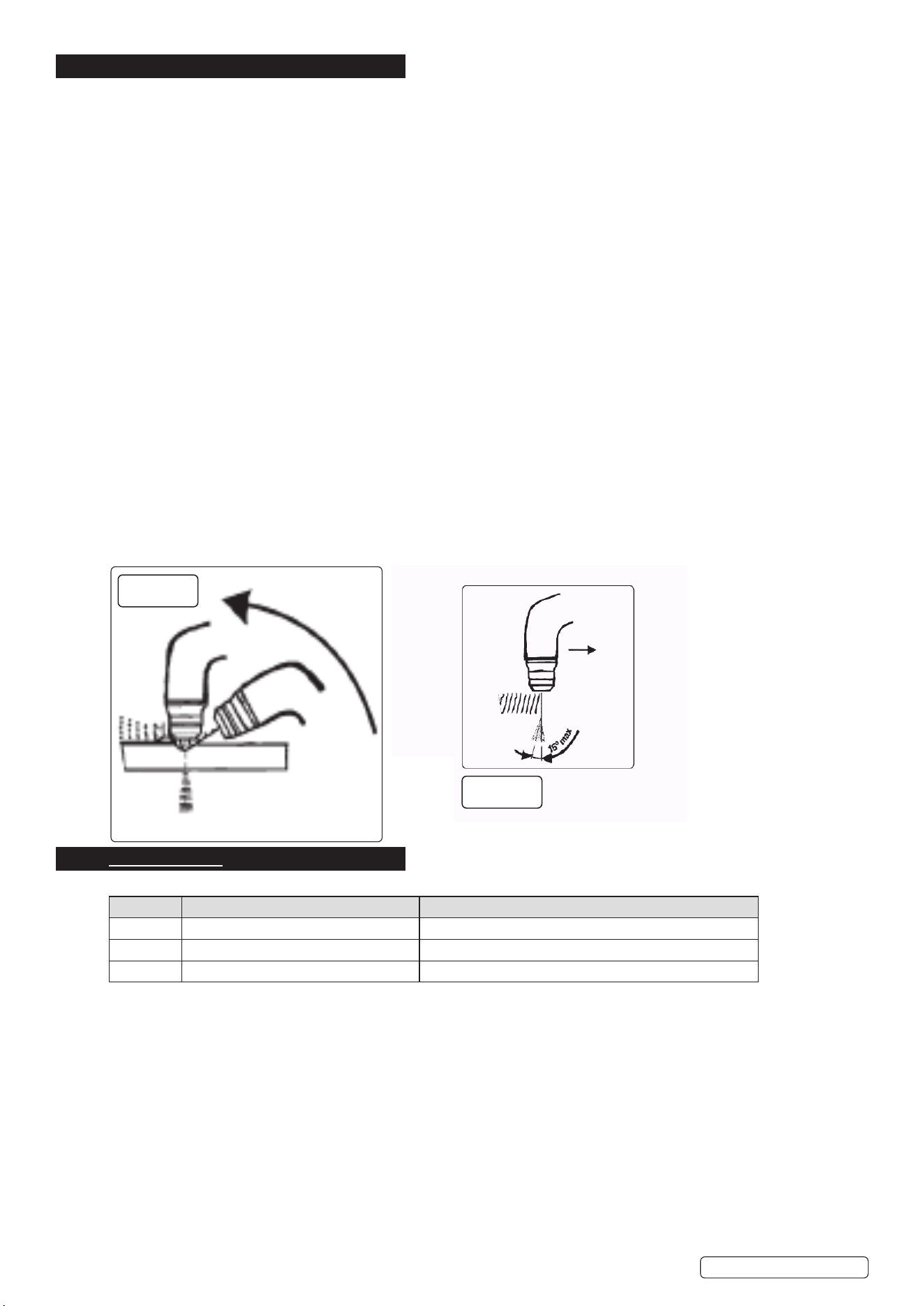
6.5.5. Start cutting. Refer to fig’s 1A , 1B below.
1. Keeping the torch perpendicular to the material to be cut, bring the torch nozzle into contact with the piece.
2. Move the torch on the surface of the piece along the ideal cutting line at a steady pace.
3. Adjust the cutting speed according to the thickness and the selected current checking that the arc coming out of the lower surface of
the piece takes on an inclination of about 15° to the vertical in the opposite direction to the direction of movement.
6.5.6. During the cutting process, the current and process parameters can be adjusted until a satisfactory cut is obtained.
6.5.7. When the cut is finished, the torch should not leave the workpiece immediately, and the post gas should be completed.
8 DO NOT touch the workpiece and torch, until fully cooled.
6.5.8. Turn off the power, turn off the gas, clean up the machine, and keep it safe.
7. FAULT CODES
When the machine stops working it will display the following fault codes:
FAULT DESCRIPTION SOLUTION
F01 Overheating. Stop work and allow to cool.
F05 Torch switch closed before turning on Loose the cutting torch
F09 The output is short-circuited. Disconnect the working circuit or check voltage sampling.
Original Language Version
© Jack Sealey Limited
fig.1A
fig.1B
PP25E Issue 3 28/08/24
8. TROUBLESHOOTING
MODE PROBLEM SOLUTION
Normal Machine cannot be turned on Check whether the input line is intact,
whether the power is turned on, and
whether the input voltage is normal
Closed torch has no output Check whether the ground cable and
control cable are properly connected
Gas leaks Check the gas lines and ttings for
leaks, and tighten or replace any faulty
connections.
Arc instability Check the ground connection, adjust the
settings according to the type of material
being welded, and replace the electrode if
necessary.
The workpiece is welded through Reduce current.
Plasma cutting Poor cutting quality Check that the cutting pressure is correct;
Reduce cutting speed appropriately;
Increase current.
The workpiece failed to be cut o Workpiece thickness is too large;
Increase the output current.
9. MAINTENANCE
WARNING! Disconnect from power supply before moving the machine or performing maintenance.
NOTE: Maintenance should only be performed by professionals.
9.1. GENERAL
9.1.1. Inspect the cables regularly for any damage or wear and tear. Replace any cables that show signs of damage, such as fraying, or cracks.
9.1.2. Check the consumables, such as tips, nozzles, and electrodes, regularly for wear and tear. Replace any consumables that are damaged
or worn out. Using damaged consumables can negatively affect the quality of your welds.
9.1.3. Check the welding machine output wiring specifications, firmness, and the cable connection screws for rust and oxidation.
9.1.4. Check the ventilation before each use. DO NOT block the fan of the running machine or touch the fan position.
8 DO NOT short-circuit the conductive nozzle and the workpiece. The short circuit will burn out the conductive nozzle. Once burned out, it
needs to be replaced, otherwise it will affect the cut quality.
9.2. TORCH
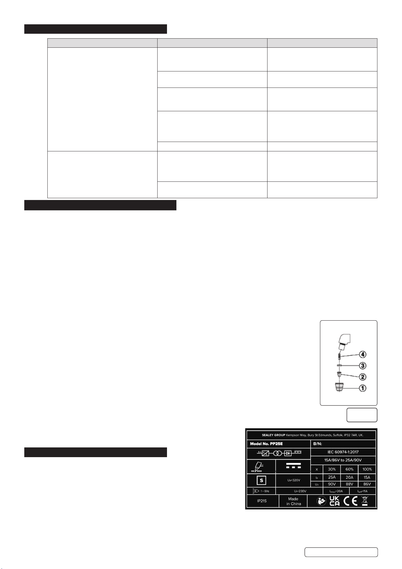
9.2.1. Check torch regularly. Maintenance will depend on frequency and type of usage and is essential for correct and safe use of the torch.
WARNING! Ensure that the torch is cool before attempting any maintenance. Always re-assemble the torch in the correct order as shown in
(fig.2). Never use tools to tighten nozzle components, hand tighten only.
9.2.2. Manually dismantle the torch nozzle head.
9.3. CAP (fig.2.1)
Clean cap and check to ensure it is not damaged (including distortion, burns, cracks). If in any doubt, replace.
9.4. ELECTRODE (fig.2.2)
Check the build-up on the emitting surface of the electrode. When the build-up is approximately 2mm replace
the electrode.
NOTE: We recommend that the electrode and nozzle are changed at the same time.
9.4.1. AIR DISTRIBUTION RING (fig.2.3)
Check that the ring is not burned or cracked and that the airflow holes are not obstructed. If damaged replace.
9.4.2. NOZZLE (fig.2.4)
If the surface is oxidised, clean with extra fine abrasive paper. Check wear of the plasma arc hole and the inner
and outer surfaces. If hole has widened, or nozzle is damaged in any way, replace it. The nozzle “V” crater
should be 1.5mm in depth.
9.5. CLEANING
9.5.1. Regularly clean the equipment to remove dirt, debris or metal shavings.
9.5.2. Use a soft brush or compressed air to clean any cooling fans, vents, or filters.
9.6. STORAGE
9.6.1. Store in a clean, dry, childproof location.
9.6.2. Cover the equipment to protect from dust and moisture.
10. RATING PLATE
10.1. The ratings plate on the inverter gives the following data:
10.1.1. Rating of internal protection provided by casing.
10.1.2. Symbol for power supply is single phase static frequency converter-
transformer-rectifier.
10.1.3. S Symbol indicates possible use of welding machine in environment potentially
subject to electrical discharge.
10.1.4. Welding Procedure: Plasma Cutting.
10.1.5. Model No.
10.1.6. Manufacturers Serial Number for welding machine identification.
10.1.7. The EUROPEAN standard relating to the safety and construction of arc welding machines.
Output.
U
º
: Maximum no load voltage.
Original Language Version
© Jack Sealey Limited
fig.2
PP25E Issue 3 28/08/24

Sealey Group, Kempson Way, Suffolk Business Park, Bury St Edmunds, Suffolk. IP32 7AR
01284 757500 sales@sealey.co.uk www.sealey.co.uk
Note: It is our policy to continually improve products and as such we reserve the right to alter data, specications and component parts without prior notice.
Important: No Liability is accepted for incorrect use of this product.
Warranty: Guarantee is 12 months from purchase date, proof of which is required for any claim.
ENVIRONMENT PROTECTION
Recycle unwanted materials instead of disposing of them as waste. All tools, accessories and packaging should be
sorted, taken to a recycling centre and disposed of in a manner which is compatible with the environment. When
the product becomes completely unserviceable and requires disposal, drain any uids (if applicable) into approved
containers and dispose of the product and uids according to local regulations.
REGISTER YOUR
PURCHASE HERE
WEEE REGULATIONS
Dispose of this product at the end of its working life in compliance with the EU Directive on Waste Electrical and Electronic Equipment
(WEEE). When the product is no longer required, it must be disposed of in an environmentally protective way. Contact your local solid
waste authority for recycling information.
Original Language Version
© Jack Sealey Limited
I
²
, U
²
: Current and corresponding normalised voltage that the welding
machine can supply during welding.
X: Welding ratio based on a 10 minute duty cycle. 30% indicates 3 minutes
welding and 7 minutes rest, 100% indicates continuous welding.
A/V-A/V: Shows the of adjustment for the welding current (min - max) at the corresponding arc voltage.
Power Supply
U1: Alternating voltage and power supply frequency of welding machine (allowed limit ± 10%).
I1 max: Maximum current absorbed by the line.
I1 eff: Effective current supplied.
PP25E Issue 3 28/08/24