7-INCH TILE SAW
Your new tool has been engineered and manufactured to WEN’s highest standards for dependability, ease
of operation, and operator safety. When properly cared for, this product will supply you years of rugged,
trouble-free performance. Pay close attention to the rules for safe operation, warnings, and cautions. If
you use your tool properly and for intended purpose, you will enjoy years of safe, reliable service.
IMPORTANT:
NEED HELP? CONTACT US!
Have product questions? Need technical support?
Please feel free to contact us at:
800-232-1195
WENPRODUCTS.COM
(M-F 8AM-5PM CST)
Model # 71707
bit.ly/wenvideo
For replacement parts visit
WENPRODUCTS.COM
NOTICE: Please refer to wenproducts.com for the most up-to-date instruction manual.
4005911

TABLE OF CONTENTS
2
3
5
6
7
8
9
10
15
19
20
21
22
PRODUCT SPECIFICATIONS
Model Number:
Motor:
Speed:
Miter Angle:
Bevel Table Angle Stops:
Cutting Wheel Dimensions:
Cutting Wheel Arbor Size:
Rip/Cross Cutting Capacity:
Miter/Diagonal Cutting Capacity:
Maximum Cutting Depth at 0° Bevel:
Maximum Cutting Depth at 22.5° Bevel:
Maximum Cutting Depth at 45° Bevel:
Product Net Weight:
Assembled Product Dimensions:
71745
120V, 60Hz, 6.5 A, S1
3450 RPM
0° to 45°
22.5° and 45°
7 x 3/32 in.
7/8 in.
18 in. (Tile Width)
12 in. (Tile Width)
1.2 in.
1 in.
0.8 in.
30.3 lbs
22-3/4 x 18-3/8 x 9-1/2 in.
Replacement diamond tile cutting blades (Model 71707B) can be
ordered at wenproducts.com
2
Product Specifications
Safety Introduction
General Safety Rules
Eletrical Information
Specific Rules for Tile Saws
Unpacking
Know Your Tile Saw
Assembly
Operation
Maintenance
Troubleshooting Guide
Warranty Statement
Exploded View & Parts List
SAFETY INTRODUCTION
Thanks for purchasing the WEN Tile Saw. If you excited about cutting tiles in half, then this is the right tool for
you. Safe operation of this tool requires that you read and understand this operator’s manual and all labels affixed
to the tool. This manual provides information regarding potential safety concerns, as well as helpful assembly and
operating instructions for your tool.
SAFETY ALERT SYMBOL: Indicates danger, warning, or caution. The safety symbols and the
explanations with them deserve your careful attention and understanding. Always follow the safety
precautions to reduce the risk of fire, electric shock and personal injury. However, please note that
these instructions and warnings are not substitutes for proper accident prevention measures.
NOTE: The following safety information is not meant to cover all possible conditions and situations that may oc-
cur. WEN reserves the right to change this product and specifications at any time without prior notice.
Keep this manual available to all users during the entire life of the tool and review it frequently
to maximize safety for both yourself and others.
3

GENERAL SAFETY RULES
WARNING! Read all safety warnings and instructions. Failure to follow all instructions may result
in electric shock, fire and serious injury. The term “power tool” in the warnings refers to your mains-
operated (corded) power tool. Save all warnings and instructions for future reference.
WORK AREA SAFETY
1. Keep work area clean and well lit. Cluttered or dark areas invite accidents.
2. Do not operate power tools in explosive atmospheres, such as in the presence of flammable liquids, gases or
dust. Power tools create sparks which may ignite the dust or fumes.
3. Keep children and bystanders away while operating a power tool. Distractions can cause you to lose control.
ELECTRICAL SAFETY
1. Power tool plugs must match the outlet. Never modify the plug in any way. Do not use any adapter plugs with
earthed (grounded) power tools. Unmodified plugs and matching outlets will reduce risk of electric shock.
2. Avoid body contact with earthed or grounded surfaces such as pipes, radiators, ranges and refrigerators. There
is an increased risk of electric shock if your body is earthed or grounded.
3. Do not expose power tools to rain or wet conditions. Water entering a power tool will increase the risk of elec-
tric shock.
4. Do not abuse the cord. Never use the cord for carrying, pulling or unplugging the power tool. Keep cord away
from heat, oil, sharp edges or moving parts. Damaged or entangled cords increase the risk of electric shock.
5. When operating a power tool outdoors, use an extension cord suitable for outdoor use. Use of a cord suitable
for outdoor use reduces the risk of electric shock.
6. If operating a power tool in a damp location is unavoidable, use a ground fault circuit interrupter (GFCI) pro-
tected supply. Use of a GFCI reduces the risk of electric shock.
PERSONAL SAFETY
1. Stay alert, watch what you are doing and use common sense when operating a power tool. Do not use a power
tool while you are tired or under the influence of drugs, alcohol or medication. A moment of inattention while
operating power tools may result in serious personal injury.
2. Use personal protective equipment. Always wear eye protection. Protective equipment such as dust mask, non-
skid safety shoes, hard hat, or hearing protection used for appropriate conditions will reduce personal injuries.
3. Do not overreach. Keep proper footing and balance at all times. This enables better control of the power tool
in unexpected situations.
4. Dress properly. Do not wear loose clothing or jewelry. Keep your hair, clothing and gloves away from moving
parts. Loose clothes, jewelry or long hair can be caught in moving parts.
5. If devices are provided for the connection of dust extraction and collection facilities, ensure these are connected
and properly used. Use of dust collection can reduce dust-related hazards.
4

GENERAL SAFETY RULES
POWER TOOL USE AND CARE
1. Do not force the power tool. Use the correct power tool for your application. The correct power tool will do
the job better and safer at the rate for which it was designed.
2. Do not use the power tool if the switch does not turn it on and off. Any power tool that cannot be controlled
with the switch is dangerous and must be repaired.
3. Prevent unintentional starting. Ensure the switch is in the off-position before connecting to power source and/
or battery pack, picking up or carrying the tool. Carrying power tools with your finger on the switch or energizing
power tools that have the switch on invites accidents.
4. Remove any adjusting key or wrench before turning the power tool on. A wrench or a key left attached to a
rotating part of the power tool may result in personal injury.
5. Disconnect the plug from the power source and/or the battery pack from the power tool before making any ad-
justments, changing accessories, or storing power tools. Such preventive safety measures reduce the risk of starting
the power tool accidentally.
6. Store idle power tools out of the reach of children and do not allow persons unfamiliar with the power tool or
these instructions to operate the power tool. Power tools are dangerous in the hands of untrained users.
7. Maintain power tools. Check for misalignment or binding of moving parts, breakage of parts and any other
condition that may affect the power tool’s operation. If damaged, have the power tool repaired before use. Many
accidents are caused by poorly maintained power tools.
8. Use the power tool, accessories and tool bits etc. in accordance with these instructions, taking into account
the working conditions and the work to be performed. Use of the power tool for operations different from those
intended could result in a hazardous situation.
SERVICE
Have your power tool serviced by a qualified repair person using only identical replacement parts. This will en-
sure that the safety of the power tool is maintained.
CALIFORNIA PROPOSITION 65 WARNING
Some dust created by power sanding, sawing, grinding, drilling, and other construction activities may contain
chemicals, including lead, known to the State of California to cause cancer, birth defects, or other reproductive
harm. Wash hands after handling. Some examples of these chemicals are:
• Lead from lead-based paints.
• Crystalline silica from bricks, cement, and other masonry products.
• Arsenic and chromium from chemically treated lumber.
Your risk from these exposures varies depending on how often you do this type of work. To reduce your expo-
sure to these chemicals, work in a well-ventilated area with approved safety equipment such as dust masks spe-
cially designed to filter out microscopic particles.
5
AMPERAGE
REQUIRED GAUGE FOR EXTENSION CORDS
25 ft. 50 ft. 100 ft. 150 ft.
6.5A 18 gauge 16 gauge 14 gauge 12 gauge
1. Examine extension cord before use. Make sure your extension cord is properly wired and in good condition.
Always replace a damaged extension cord or have it repaired by a qualified person before using it.
2. Do not abuse extension cord. Do not pull on cord to disconnect from receptacle; always disconnect by pulling
on plug. Disconnect the extension cord from the receptacle before disconnecting the product from the extension
cord. Protect your extension cords from sharp objects, excessive heat and damp/wet areas.
3. Use a separate electrical circuit for your tool. This circuit must not be less than a 12-gauge wire and should be
protected with a 15A time-delayed fuse. Before connecting the motor to the power line, make sure the switch is in
the OFF position and the electric current is rated the same as the current stamped on the motor nameplate. Run-
ning at a lower voltage will damage the motor.
GUIDELINES FOR USING EXTENSION CORDS
When using an extension cord, be sure to use one heavy enough to carry the current your product will draw. An
undersized cord will cause a drop in line voltage resulting in loss of power and overheating. The table below shows
the correct size to be used according to cord length and nameplate ampere rating. When in doubt, use a heavier
cord. The smaller the gauge number, the heavier the cord.
GROUNDING INSTRUCTIONS
This tool is equipped with an electric cord that has an equipment grounding conductor and a grounding plug. In
the event of a malfunction or breakdown, grounding provides the path of least resistance for an electric current and
reduces the risk of electric shock. The plug must be plugged into a matching outlet that is properly installed and
grounded in accordance with all local codes and ordinances.
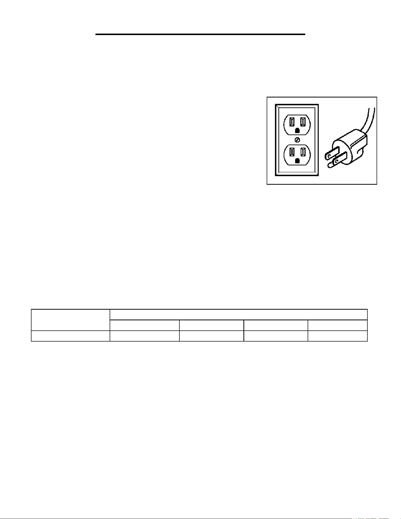
1. Use only three-wire extension cords that have three-pronged plugs and
outlets that accept the tool’s plug as shown in Fig. A. Do not modify the plug
provided. If it will not fit the outlet, have the proper outlet installed by a li-
censed electrician.
2. Improper connection of the equipment grounding conductor can result in
electric shock. The conductor with the green insulation (with or without yel-
low stripes) is the equipment grounding conductor. If repair or replacement
of the electric cord or plug is necessary, DO NOT connect the equipment
grounding conductor to a live terminal.
3. Repair or replace a damaged or worn cord immediately.
CAUTION: Check with a licensed electrician or service personnel if you do not completely understand the
grounding instructions or whether the tool is properly grounded.
ELECTRICAL INFORMATION
6
Fig. A

AMPERAGE
REQUIRED GAUGE FOR EXTENSION CORDS
25 ft. 50 ft. 100 ft. 150 ft.
6.5A 18 gauge 16 gauge 14 gauge 12 gauge
CUTTING WHEEL SAFETY
1. Use only diamond cutting wheels that are rated above the maximum spindle speed of the tool (3450 RPM) and
are appropriate for the material being cut.
2. Use cutting wheels in good working condition. Never use segmented cutting wheels. Replace damaged or worn
cutting wheels immediately. Regularly check to ensure that the cutting wheel is correctly fastened to the tool.
3. Use protective gloves when handling cutting wheels. Cutting wheels can cause injuries, even when stationary.
TILE SAW SAFETY
1. Make sure the tile saw is securely positioned or mounted on a level, firm work surface before operating.
2. To reduce the risk of electrocution, keep all connections dry and off the ground. Do not touch plug with wet
hands. Refer to “Positioning of the Tile Saw” on page 10 for instructions on arranging a “drip loop” in the power
cord to prevent water from entering the power outlet.
3. If any part of this tool is missing, broken, bent, or damaged in any way, shut off the power switch, disconnect the
power, and have the part replaced before operation. Never use the machine without the blade guard in position.
4. Wear ANSI Z87.1-approved impact-resistant safety goggles. Safety goggles should be worn during operation, as-
sembly or maintenance of the tool.
5. Always stand to the side of the cutting wheel. Never stand or have any part of your body in line with the path of
the wheel. Maintain a sufficient and safe distance from the cutting wheel.
6. Before turning on the tool, make sure the workpiece is not in contact with the cutting wheel. Let the cutting wheel
reach full speed before feeding in the workpiece.
7. This saw is for cutting tiles; never cut wood or metal with this saw. Do not exceed the cutting capacity of your saw.
8. Cut only one workpiece at a time. Do not stack workpieces on top of each other. Multiple workpieces can shift
during cutting and fly out of control.
9. Keep the water level between the minimum and maximum level markings on the inside of the water reservoir. Do
not operate the tile saw with too little or too much water. Lack of water in the reservoir may damage the tile blade.
10. Switch off the tile saw and wait until the cutting wheel comes to a complete stop before removing workpieces or
residual material from the work area.
11. This tile saw should be used at an ambient temperature between 59°F and 86°F (15°C and 30°C).
12. To avoid accidentally starting the tool, always disconnect the product from its power supply before performing
adjustments or maintenance.
13. Use only recommended accessories. The use of improper accessories may cause risk of injury to persons.
14. Always store the product in a dry and frost-free place. Keep the tool and cutting wheels away from children.
SPECIFIC RULES FOR TILE SAWS
7
8
UNPACKING
Unpack carton; check you machine to see parts listed below:
A. Rip guide X1
B. Miter guide X1
C. Knob X1
D. Splash hood X1
E. Hex bolt X1
F. Splash hood bracket X1
G. Cutting wheel X1
H. Tile saw X1
I. Operator’s manual X1
WARNING:
If any parts are damaged or missing do not operate this tool until the parts are replaced. Use of this product
with damaged or missing parts could result in serious personal injury.
This product requires assembly. Do not connect to power supply until assembly is complete. Failure to comply
could result in accidental starting and possible serious personal injury
A
B
C D
E
F
G
H
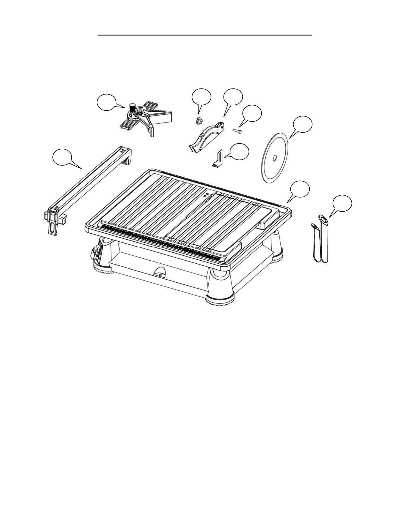
UNPACKING
Carefully remove the tool and all parts from the packaging. Check all components against the packing list diagram
below. If any part is damaged or missing, please contact our customer service at (800) 232-1195, M-F 8-5 CST or
email us at [email protected].
A.
B.
C.
D.
E.
Rip Guide
Miter Guide
Blade Guard Knob
Blade Guard
Hex Bolt
F.
G.
H.
I.
PACKING LIST
Blade Guard Bracket
Cutting Wheel
Tile Saw
Wrench (x2)
8
UNPACKING
Unpack carton; check you machine to see parts listed below:
A. Rip guide X1
B. Miter guide X1
C. Knob X1
D. Splash hood X1
E. Hex bolt X1
F. Splash hood bracket X1
G. Cutting wheel X1
H. Tile saw X1
I. Operator’s manual X1
WARNING:
If any parts are damaged or missing do not operate this tool until the parts are replaced. Use of this product
with damaged or missing parts could result in serious personal injury.
This product requires assembly. Do not connect to power supply until assembly is complete. Failure to comply
could result in accidental starting and possible serious personal injury
A
B
C D
E
F
G
H
I
8
8
UNPACKING
Unpack carton; check you machine to see parts listed below:
A. Rip guide X1
B. Miter guide X1
C. Knob X1
D. Splash hood X1
E. Hex bolt X1
F. Splash hood bracket X1
G. Cutting wheel X1
H. Tile saw X1
I. Operator’s manual X1
WARNING:
If any parts are damaged or missing do not operate this tool until the parts are replaced. Use of this product
with damaged or missing parts could result in serious personal injury.
This product requires assembly. Do not connect to power supply until assembly is complete. Failure to comply
could result in accidental starting and possible serious personal injury
A
B
C D
E
F
G
H
CLEANING THE SURFACES
Your tool comes protected with a layer of anti-rust coating. Remove the protective coating from surfaces using a
soft cloth, moistened with kerosene (do not use cellulose-based solvents such as paint thinner or lacquer thinner, as
these will damage the painted surfaces).
KNOW YOUR TILE SAW
Learn the parts and controls of your tile saw. This product requires assembly: follow the assembly instructions on
the following pages. Do not connect to the power supply until it is properly assembled. Failure to comply could
result in personal injury and product damage.
7
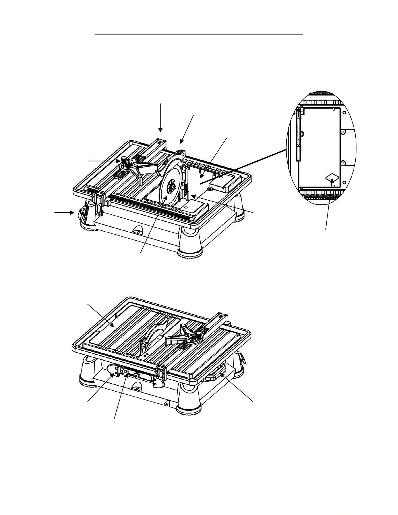
KNOW YOUR TILE SAW
This saw is designed to cut man-made tile, pavers, and stone tile products only.
Rip guide
Miter guide
Switch
Splash hood
Cutting wheel
Bevel table
Lifting handle
Water reservoir
Cord storage
Wrench
Max. water
fill line
Overflow drain
9
Blade guard
Lifting Handle
Overflow Relief/Drain Plug
Max.
Water Fill Line
Wrench
Cord Storage
Bevel Table
Cutting Wheel
Miter Guide
Rip Guide
Blade Guard
Water Reservoir
WARNING: To prevent serious injury from accidental operation, make sure the power cord is discon-
nected from the power source and the tool is turned OFF before assembly or making any adjustments.
ASSEMBLY
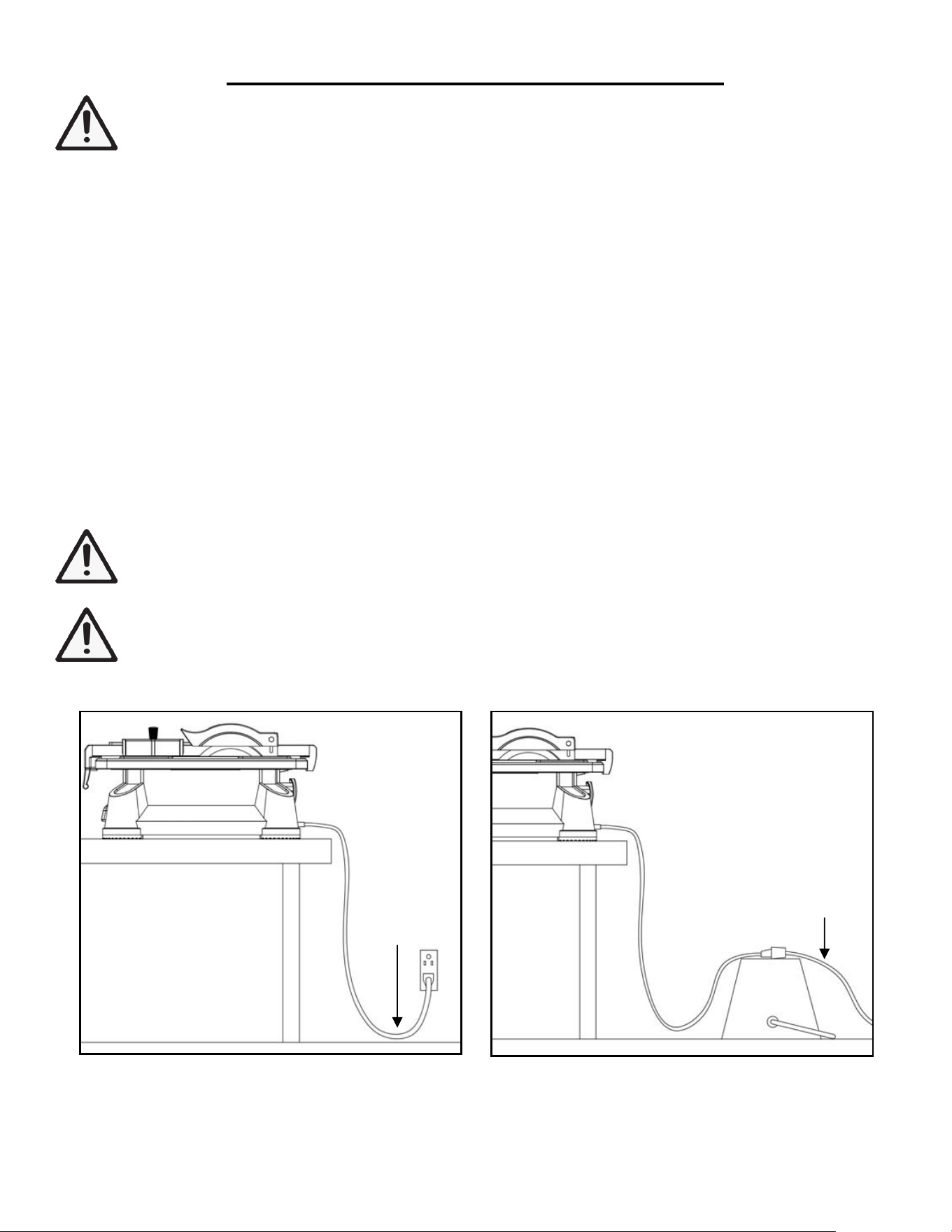
POSITIONING OF THE TILE SAW (Figs. 1 & 2)
Place the tile saw on a firm, level surface. Allow sufficient area around the tile saw and be prepared that the sur-
rounding area may get wet during operation.
Tile saws require water to cool down the cutting wheel. However, water contacting the power source or entering a
power tool will increase the risk of electric shock. To avoid the possibility of the power plug or receptacle getting
wet, the tile saw should be positioned to one side of a wall mounted receptacle (not directly above it). This prevents
water from dripping directly onto the receptacle or power plug.
Create a "drip loop" in the cord connecting the tool to the receptacle (Fig. 1). A “drip loop” is the part of the cord
that is below the level of the receptacle or the connector (if an extension cord is used). This will prevent the water
from traveling down along the cord and coming in contact with the receptacle.
If an extension cord is used, the cord connection must be placed on the elevated surface and the “drip loop” must
be arranged before the cord connection (Fig. 2) to prevent it from getting wet.
WARNING: If the plug or receptacle does get wet, DO NOT unplug the cord. First disconnect the fuse
or circuit breaker that supplies power to the tool. Then, unplug the tool and examine for presence of
water in the receptacle.
WARNING: To reduce the risk of electrocution, keep all connections dry and off the ground. Do not
touch the plug with wet hands.
6
WARNING: Improper connection of equipment grounding
conductor can result in the risk of electrical shock. Equipment
should be grounded while in use to protect operator from electrical
shock.
-Check with a qualified electrician if you do not understand
grounding instructions or if you are in doubt as to whether the tool
is properly grounded.
-This tool is equipped with an approved cord and a 3-prong
grounding type plug for you protection against shock hazards.
-Grounding plug should be plugged directly into a properly installed and grounded 3-prong grounding-type
receptacle, as shown.
-Do not remove or alter grounding prong in any manner, in the event of a malfunction or breakdown,
grounding provides a path of least resistance for electrical shock.
▲GUIDELINES FOR EXTENSION CORDS
USE PROPER EXTENSION CORD. Make sure your extension cord is in good condition. When using an
extension cord, be sure to use one heavy enough to carry the current your product will draw. An undersized
cord will cause a drop in line voltage, resulting in loss of power and cause overheating.
Be sure your extension cord is properly wired and in good condition. Always replace a damaged
extension cord or have it repaired by a qualified person before using it. Protect your extension cords from
sharp objects, excessive heat and damp or wet areas.
POSITION OF THE TILE SAW
To avoid the possibility of the tool plug or outlet
getting
wet, position tile saw to one side of a wall-mounted
outlet
to prevent water from dripping onto the outlet or plug. The operator should
arrange
a “drip loop” in the
cord
connecting
the saw to the outlet.
The
“drip loop” is that part of the
cor
d
below the
level
of the outlet, or the
connector if an extension cord is used, to prevent water traveling along the cord
and
coming in contact with
the
outlet.
If the plug or outlet does get wet, DO NOT unplug the
cord.
Disconnect the fuse or circuit breaker that supplies
power
to the tool then unplug and examine for the presence
of
water in the
outlet.
WARNING:
To reduce the risk of electrocution, keep all
con
nections dry and off the ground. Do not touch
the
plug with wet hands.
Drip loop
Extension cord
Fig. 1 Fig. 2
10
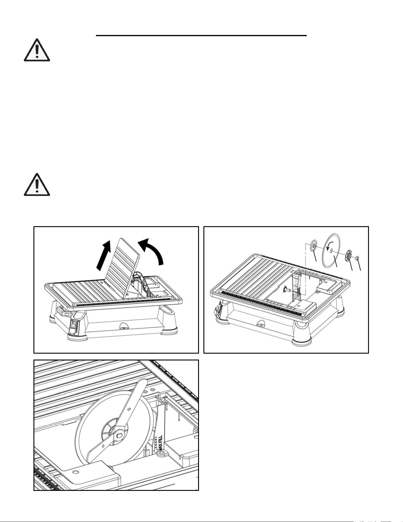
INSTALLING THE TILE CUTTING WHEEL (Figs. 3, 4 & 5)
1. Unplug the saw, flip up and remove the bevel table (Fig. 3).
2. Remove the arbor nut (Fig. 4 - 1) and outer flange (Fig. 4 - 2), leaving the inner flange (Fig. 4 - 4) on the arbor.
3. Install the cutting wheel (Fig. 4 - 3) against the inner flange, with the arrow on wheel going in the counterclockwise
direction.
4. Reinstall the outer flange (Fig. 4 - 2). Replace the arbor nut (Fig. 4 - 1) on the arbor. Using the two wrenches in-
cluded, tighten arbor nut securely (Fig. 5).
WARNING: Use only cutting wheels that are suitable for your tile saw. Do not use wheels with a speed
rating less than 3450 RPM. Make sure the edge of the blade is smooth and free of openings or grooves.
Replacement cutting wheels (Part No. 71707B) can be purchased from wenproducts.com.
9
ASSEMBLY INSTRUCTIONS
▲INSTALLING THE TILE CUTTING WHEEL
1. Unplug the saw and remove the bevel table.
2. Remove the arbor nut and outer flange leaving the inner flange on the arbor.
3. Fix the cutting wheel snug against the inner flange with the arrows on wheel going in the counterclockwise
direction.
4. Replace the outer flange. The “D” flat on the outer flange aligns with the flats on the arbor.
5. Replace the arbor nut on the arbor. Using the two wrenches, tighten arbor nut securely.
▲
INSTALLING THE SPLASH
HOOD
1. Slide the splash hood bracket into the lip under the table behind the cutting wheel. Align the two slot of
splash hood bracket with the two flat head screw.
2. Align the hood bracket with the cutting wheel so that it does not interfere with the material being cut. Tighten
the two flat head screw.
3. Slide the splash hood over the bracket and align the holes in splash hood with the slot in the splash hood
bracket.
4. Insert the hex bolt through hood and bracket. Thread the knob onto the bolt and tighten to the desired
height. Always adjust the splash hood horizontally to the table and slightly above tile thickness.
WARNING: To prevent serious injury from accidental operation, make sure the power cord is discon-
nected from the power source and the tool is turned OFF before assembly or making any adjustments.
ASSEMBLY
Fig. 3
Fig. 5
Fig. 4
1
2
3
4
11
WARNING: To prevent serious injury from accidental operation, make sure the power cord is discon-
nected from the power source and the tool is turned OFF before assembly or making any adjustments.
ASSEMBLY
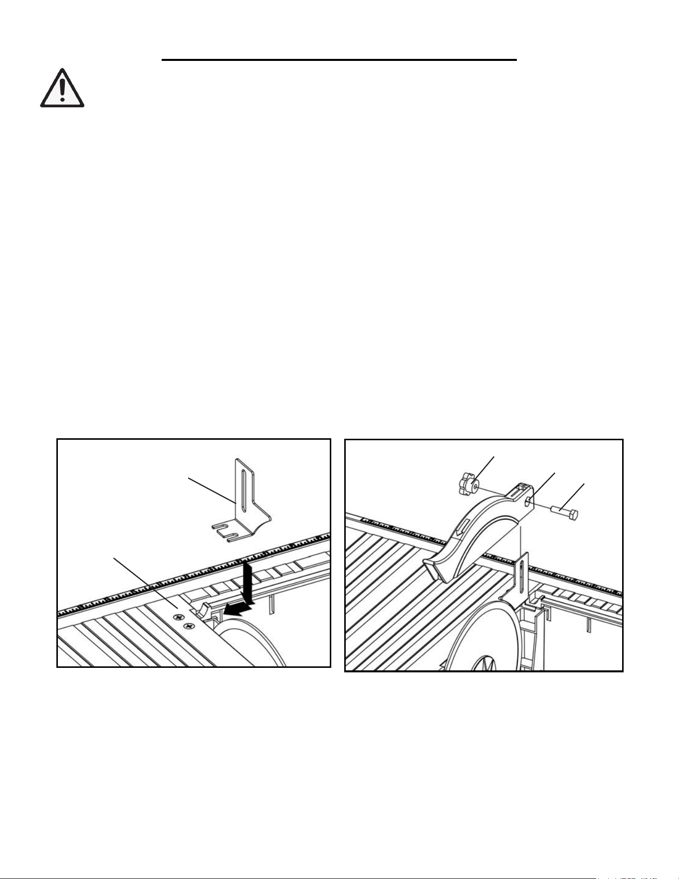
INSTALLING THE BLADE GUARD (Figs. 6 & 7)
1. Slide the blade guard bracket (Fig. 6 - 1) into the lip under the table behind the cutting wheel. Align the two slots
of the blade guard bracket with the two flat head screws (Fig. 6 - 2). Position the blade guard bracket between the
tabletop and the locking plate.
2. Position the bracket so that it is parallel with the cutting wheel. Using a Phillips head screwdriver (not included),
tighten the two flat head screws to secure the blade guard bracket in place.
3. Slide the blade guard over the bracket, align the holes (Fig. 7 - 1) in the blade guard with the slot in the blade
guard bracket.
4. Insert the hex bolt (Fig. 7 - 2) through the blade guard and bracket, and thread the knob (Fig. 7 - 3) onto the bolt.
Set the blade guard to the desired height and tighten the knob.
NOTE: Do not over-tighten the protective guard. The guard should rise and fall freely as the workpiece is pushed
towards the wheel during cutting operation. Ensure the protective guard cannot touch the cutting wheel.
NOTE: Before each operation, check the blade guard height to make sure it sits slightly above the tile. Adjust the
height if necessary. This will provide the maximum protection.
01
▲
INSTALLING THE RIP GUIDE AND MITER GUIDE
1. Place the rip guide on the saw
table.
2. Use the rip guide scale, located on front and rear of the table,
to
set the rip guide to the desired width of
cut.
3. Push the locking lever down to secure to the saw
table.
4. Align the male dovetail under the miter guide with the dovetail
gr
oove in the top of the rip
guide.
5. Push the miter guide onto the rip guide to the desir
ed
operating
position
▲FILLING/CHANGING THE
WATER
RESERVOIR
1.
Fill the water reservoir with clean tap water. Do not try to fill the water upper than max fill line. The water will
overflow from the overflow drain.
2. To change reservoir
water:
Unplug the saw.
Remove
the overflow drain and empty waste water into a bucket. Do not allow the water
to splash onto the
gr
ound
or around the machine. Rinse the machine
thor
oughly
.
Discard the waste water in
accordance with local r
egula
tions.
Firmly push the overflow drain into the hole in the
bottom
of the water fill
reservoir. Replace
with clean
water
.
Fig. 6
Fig. 7
1
1
2
3
2
12
INSTALLING THE RIP GUIDE (Fig. 8)
1. Place the rip guide (Fig. 8 - 1) onto the saw table, with the locking lever (Fig. 8 - 2) in the unlocked (raised) posi-
tion.
2. Refer to the rip guide scale on the front and rear of the table and set the rip guide to the desired width of cut.
3. Push the locking lever (Fig. 8 - 2) down to secure the rip guide onto the saw table.
NOTE: If the rip guide is loose, tighten the 6mm nut on the end of the guide (71707-071), and try again. Make
adjustments to the nut as necessary.
INSTALLING THE MITER GUIDE (Fig. 9)
1. Slide the miter guide onto the rip guide.
2. The miter angle can be adjusted from 0° to 45°. Loosen the miter guide knob (Fig. 9 - 1) and rotate the guide to
the desired angle. Tighten the miter guide knob to lock the miter guide’s angle.
WARNING: To prevent serious injury from accidental operation, make sure the power cord is discon-
nected from the power source and the tool is turned OFF before assembly or making any adjustments.
ASSEMBLY
01
▲
INSTALLING THE RIP GUIDE AND MITER GUIDE
1. Place the rip guide on the saw
table.
2. Use the rip guide scale, located on front and rear of the table,
to
set the rip guide to the desired width of
cut.
3. Push the locking lever down to secure to the saw
table.
4. Align the male dovetail under the miter guide with the dovetail
gr
oove in the top of the rip
guide.
5. Push the miter guide onto the rip guide to the desir
ed
operating
position
▲FILLING/CHANGING THE
WATER
RESERVOIR
1.
Fill the water reservoir with clean tap water. Do not try to fill the water upper than max fill line. The water will
overflow from the overflow drain.
2. To change reservoir
water:
Unplug the saw.
Remove
the overflow drain and empty waste water into a bucket. Do not allow the water
to splash onto the
gr
ound
or around the machine. Rinse the machine
thor
oughly
.
Discard the waste water in
accordance with local r
egula
tions.
Firmly push the overflow drain into the hole in the
bottom
of the water fill
reservoir. Replace
with clean
water
.
Fig. 8 Fig. 9
1
2
1
13
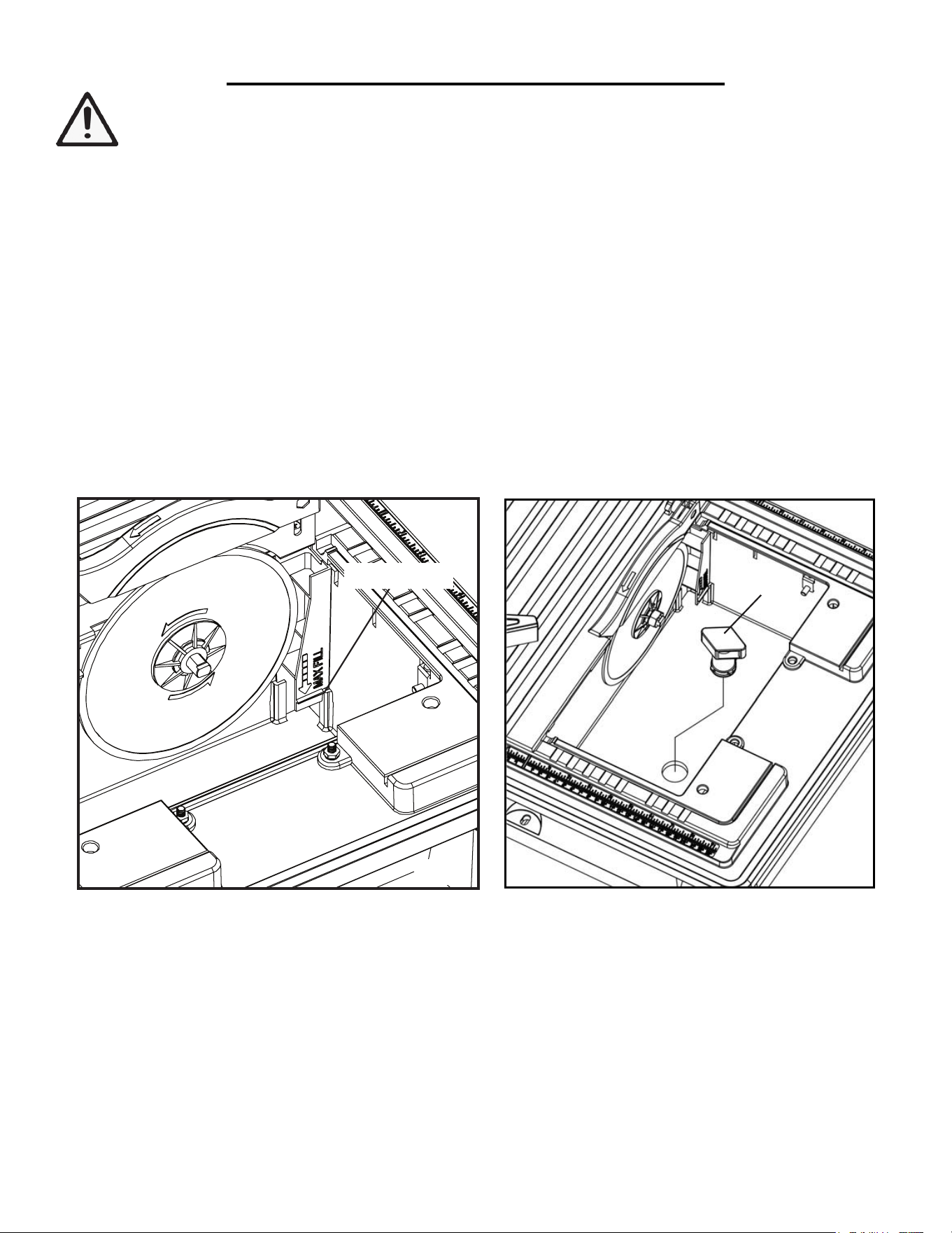
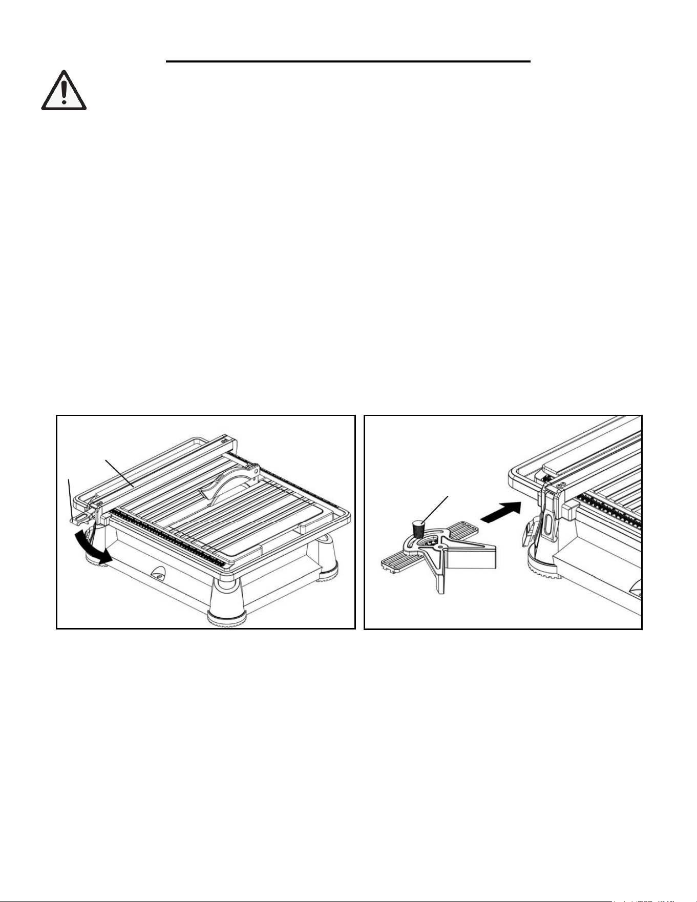
FILLING/EMPTYING THE WATER RESERVOIR (Figs. 10 & 11)
1. Remove the bevel table to access the water reservoir. Push down firmly on the water drain plug (Fig. 11 - 1) to
avoid water from leaking out.
2. Fill the water reservoir with water up to the maximum fill line marked on the inside of the reservoir (Fig. 10). Do
not add chemicals or detergents to the water.
To empty the reservoir water:
1. After operation, turn off the tool and disconnect the power supply. Place the water reservoir drain hole over a
container large enough to hold the water. Pull out the water drain plug (Fig. 11 - 1) and drain the waste water. Do not
allow water to splash onto the ground or around machine. Discard waste water in accordance with local regulations.
2. Clean the water reservoir after each use to avoid build-up.
ASSEMBLY
WARNING: To prevent serious injury from accidental operation, make sure the power cord is discon-
nected from the power source and the tool is switch to OFF before assembly or making any adjustments.
11
▲
REPLACE THE BEVEL TABLE
Fix the bevel table to main table, set the two legs between the pins and the wall of water reservoir.
Tilt the bevel table to the horizontal position.
OPERATING INSTRUCTIONS
Always draw the line to be cut on the tile using a marker
or
grease pencil. If the tile is shiny and hard-to-mark,
place
masking tape on the tile and mark the
tape.
A common problem when cutting tile is straying from
the
marked
line.
Once you’ve strayed from the mark,
you can
no
t
force the wheel back to the line by twisting the tile. Instead, back up and recut the tile slicing off a
small amount of
tile
until the wheel is back on
track.
To avoid this problem, use the rip guide when making
cr
oss
cuts, the miter guide for miter cuts and the bevel
table
for
making bevel cuts, whenever
possible.
Another problem is cutting difficult material. To prevent
chip
ping of the material at the end of the cut: first cut
1-1/2 in. of the material then turn off the saw; flip the material
ar
ound
180º and make the
cut.
Clean the saw table, rip and miter guides, and bevel
table
frequently during use. Debris from the cut
Pin
Leg
Wall
Fig. 10 Fig. 11
Max Fill Line
1
CAUTION: Do not operate the tile saw with too little or too much water in the water reservoir. Make sure there
it enought water to cool the cutting wheel as it rotates.
14
OPERATION
WARNING: To prevent serious injury, make sure all the warnings and instructions have been read and
understood before operating this tool.
PREPARING FOR OPERATION
1. Before each use, inspect the general condition of the tool. Do not operate if any portion of the tool, power switch,
power cord, or cutting wheel is damaged, inoperable, or altered. Any issues with the tool should be repaired or
replaced before use.
2. Make sure that the tile saw is securely placed on a firm, level surface.
3. Check that all parts of the machine are properly assembled and all safety guards are in place.
4. Refer to “Positioning of the Tile Saw” on page 10 to arrange the power cord with enough length to create a “drip
loop” to reduce the risk of electric shock.
5. Check that the water is filled up to the maximum water line marked on the inside of the tank (Fig. 10, p. 14).
WARNING: Stop the machine immediately if there is excessive vibration or any other abnormal feed-
back (vibrations, noises, etc.). Have the machine checked by a qualified technician before operation.
Refer to the instructions on the following pages for making specific types of cuts.
OPERATING THE TILE SAW
1. Plug the power cord into the power supply.
2. Make sure the workpiece is not contacting the cutting wheel during startup. Push the power switch to ON, and
the machine will start. Allow the wheel to reach full speed before performing any cutting operations.
3. To switch off the machine, push the power switch to OFF. The wheel will continue to rotate for a few seconds
after the machine has been switched off. Wait for the wheel to stop completely before removing the workpiece or
making any adjustments.
4. After use, turn off the tool and disconnect the power supply. Place the water reservoir drain hole over a container
large enough to hold the water. Pull out the tank drain plug and drain the water. Clean the water reservoir.
15
OPERATION
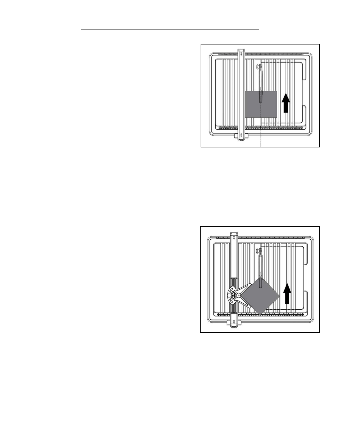
MAKING A CROSS CUT (Fig. 14)
Cross cuts are straight cuts, where the material is fed into the cutting
wheel cut at a 90° angle. The width of the tile should be shorter than
18 inches.
1. Using a marker or grease pencil, mark the line of cut on the tile.
2. Position the rip guide at the desired cutting width from the cut-
ting wheel and securely lock the lever.
3. Place the tile on the table and seat it firmly against the rip guide.
Make sure the material is clear of the cutting wheel before turning
on the saw.
4. Turn the power switch to the ON position. Let the cutting wheel
12
material can interfere with tool
function.
TO MAKE A CROSS
CUT
Cross cuts are straight 90° cuts. The material is fed into
the
cut at a 90° angle to the wheel.
1. Using a marker or grease pencil, mark the area to be
cut
on material.
2. Remove the miter
guide.
3. Position the rip guide the desired distance from the
wheel for the cut and securely lock the lever.
4. Place the material on the table and firmly against the
rip
guide.
5. Make
sure
the material is
clear
of the cutting
wheel
befor
e
turning on the saw.
6. Turn the on/off switch to the ON
position.
7. Let the cutting wheel build up to full speed and wait
for
the wheel to get wet before moving the material into
the
wheel.
8. Hold the material firmly against the rip guide and feed the material into the cutting wheel.
9. When the cut is made, turn the saw OFF. Wait for
the
cutting wheel to come to a complete stop before
removing any part of the material.
TO MAKE A 45° DIAGONAL
CUT
45° Diagonal cuts
are
also referred to as “long
point-to-long
point
cuts”.
1. Using a marker or grease pencil, mark the area to be
cut
on material.
2. Install the miter
guide.
3. Adjust miter guide to
45°
using angle scale and
tighten
securely with lock
knob.
4. Position the rip guide the desired distance from the
wheel for the cut and securely lock the lever.
5. Place the material on the table and firmly against the
rip
guide.
6. Make
sure
the material is
clear
of the cutting
wheel
befor
e
turning on the saw.
7. Turn the on/off switch to the ON
position.
8. Let the cutting wheel build up to full speed and wait
for
the wheel to get wet before moving the material
into
the
wheel.
9. Hold the material firmly against the miter guide and slide miter guide along rip guide. Feed the material
into
the
cutting wheel.
10. When the cut is made, turn the saw OFF. Wait for
the
cutting wheel to come to a complete stop before
removing any part of the material.
Fig. 14
Fig. 15
build up to full speed and wait for the wheel to get wet feeding the material into the cutting wheel.
5. Hold the material firmly against the rip guide and feed the material into the cutting wheel in a smooth motion
(Fig. 14). Hold down on the edges of the tile to prevent the tile from lifting during the cut.
6. When the cut is completed, turn the saw OFF. Wait for the cutting wheel to come to a complete stop before
removing any part of the tile.
MAKING A MITER CUT (Fig. 15)
The tile can be cut at a miter angle from 0 to 45 degrees, by setting
the miter guide. The width of the tile should be shorter than 12
inches.
1. Using a marker or grease pencil, mark the line of cut on the tile.
2. Install the miter guide on top of the rip guide. Adjust the miter
guide to the desired miter angle using angle scale and securely
tighten the lock knob.
3. Position the rip guide the desired distance from the cutting
wheel and securely lock the rip guide lever.
4. Place the tile on the table and with the corner held firmly inside
the miter guide. Make sure the material is clear of the cutting wheel before turning on the saw.
5. Turn the power switch to the ON position. Let the cutting wheel build up to full speed and wait for the wheel to
get wet feeding the material into the cutting wheel.
6. Hold the tile firmly against the miter guide and rip guide, and feed the material into the cutting wheel in a
smooth motion (Fig. 15). Hold down on the edges of the tile to prevent the tile from lifting during the cut.
7. When the cut is finished, turn the saw OFF. Wait for the cutting wheel to come to a complete stop before
removing any part of the material.
16
OPERATION
WARNING: To prevent serious injury, make sure all the warnings and instructions have been read and
understood before operating this tool.
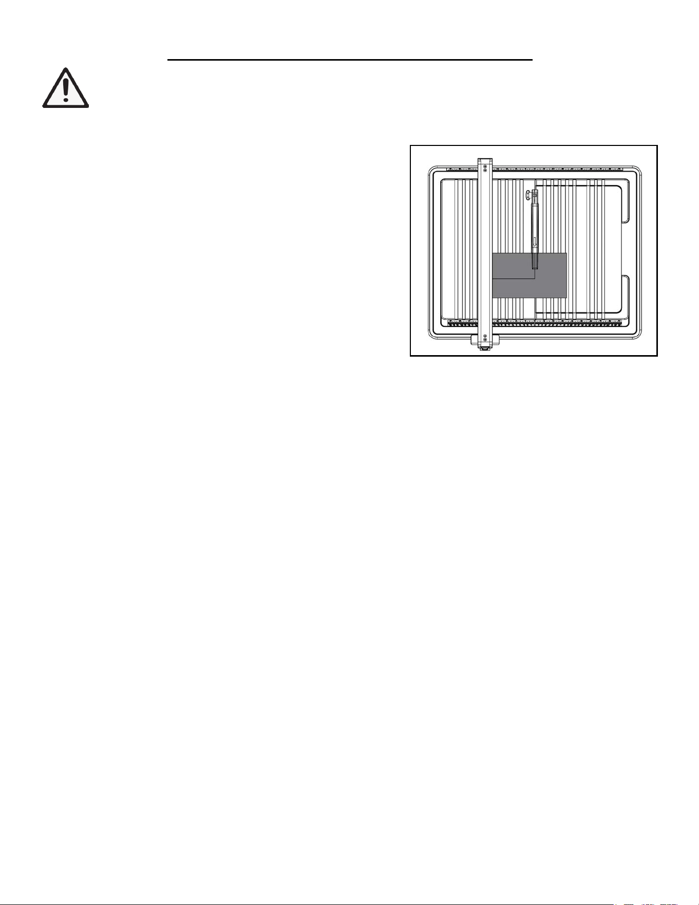
MAKING AN L-CUT (Fig. 16)
L-cuts are used to remove a piece of tile to so that it can fit in a
corner or around a cabinet.
1. Using a marker or grease pencil, mark the line of cut on the tile.
2. Position the rip guide at the desired cutting width from the cut-
ting wheel and securely lock the lever.
3. Place the tile on the table and seat it firmly against the rip guide.
Make sure the material is clear of the cutting wheel before turning
on the saw.
4. Turn the power switch to the ON position. Let the cutting wheel
build up to full speed and wait for the wheel to get wet feeding the
13
TO MAKE A MITER
CUT
Miter cuts are used for cutting outside and inside
cor
ners
on material, decorative chair rail, and base
molding
with
the material at any angle to the wheel other than 90°.
Miter
cuts tend to “creep” during cutting.
This can be
contr
olled
by holding the workpiece securely against the miter
guide.
1. Using a marker or grease pencil, mark the area to be
cut
on material.
2. Install the miter
guide.
3. Position the rip guide the desired distance from the
wheel for the cut and securely lock the lever.
4. Set the miter guide to desired angle using the miter
guide
scale, and tighten securely with lock
knob.
5. Place the material on the table and firmly against the
rip
guide.
6. Make
sure
the material is
clear
of the cutting
wheel
befor
e
turning on the saw.
7. Turn the on/off switch to the ON
position.
8. Let the cutting wheel build up to full speed and wait
for
the wheel to get wet before moving the material
into
the
wheel.
9. Hold the material firmly against the miter guide and slide miter guide along rip guide. Feed the material
into
the
cutting wheel.
10. When the cut is made, turn the saw OFF. Wait for
the
cutting wheel to come to a complete stop before
removing any part of the material.
TO MAKE AN
L-CUT
L-cuts are cuts that remove a piece of tile to fit in a
cor
ner
,
around a cabinet, or a piece of molding and are
made
by
two separate
cuts.
NOTE: Only overcut on the bottom or underneath
side
of
the material being
cut.
1. Using a marker or grease pencil, mark the area
to be
cut
on material.
2. Remove the miter
guide.
3. Position the rip guide the desired distance from
the wheel for the cut and securely lock the
lever.
4. Place the material on the table and firmly
against the
rip
guide.
5. Make sur
e
the
material is
clear
of
the
cutting
wheel
befor
e
turning on the saw.
6. Turn the on/off switch to the ON position.
7. Let the cutting wheel build up to full speed and wait for the wheel to get wet before moving the material
into the wheel.
material into the cutting wheel.
5. Hold the material firmly against the rip guide and feed the material into the cutting wheel in a smooth motion.
Make the cut far enough into the material without over-cutting (Fig. 16).
6. Slide the material back and away from the cutting wheel. Adjust the material, adjust the rip guide, and make the
second cut. This time, over-cut the line and the workpiece should separate from the rest of the material.
7. When the cut is finished, turn the saw OFF. Wait for the cutting wheel to come to a complete stop before
removing any part of the tile.
Fig. 16
17
14
8. Hold the material firmly against the rip guide and feed the material into the cutting wheel.
9. Make the cut far enough into the material without over- cutting.
10. When the cut is made, turn the saw OFF. Wait for the cutting wheel to come to a complete stop before
removing any part of the material.
11. Turn the material, adjust the rip guide, and make the second cut along one of the marks. This time
overcut the other line and the cut piece should separate from the rest of the material.
12. When the second cut is made, turn the saw OFF. Wait for the cutting wheel to come to a complete stop
before removing any part of the material.
TO MAKE A
BEVEL
CUT
Beveled 22.5° and 45° cuts can be made using the bevel
table.
1. Using a marker or grease pencil, mark the area to be
cut
on material.
2. Remove the rip
guide.
3. Tilt the bevel
table.
Align the positioning grooves on the both bevel table legs with the two pins. Set the
bevel table to 22.5
º or 45 º.
NOTE: Make sure bevel table is locked firmly in place before beginning
cut.
4. Turn the on/off switch to the ON
position.
5. Let the cutting wheel build up to full speed and wait
for
the wheel to get wet before moving the
material into
the
wheel.
6. Hold the material firmly against the bevel table and feed the material into the cutting wheel.
7. When the cut is made, turn the saw OFF. Wait for
the
cutting
w
heel
to come to
a
complete stop
b
ef
o
r
e
rem
o
v
ing
any part of the material.
22.5 º
45 º
Leg
Pin
14
8. Hold the material firmly against the rip guide and feed the material into the cutting wheel.
9. Make the cut far enough into the material without over- cutting.
10. When the cut is made, turn the saw OFF. Wait for the cutting wheel to come to a complete stop before
removing any part of the material.
11. Turn the material, adjust the rip guide, and make the second cut along one of the marks. This time
overcut the other line and the cut piece should separate from the rest of the material.
12. When the second cut is made, turn the saw OFF. Wait for the cutting wheel to come to a complete stop
before removing any part of the material.
TO MAKE A
BEVEL
CUT
Beveled 22.5° and 45° cuts can be made using the bevel
table.
1. Using a marker or grease pencil, mark the area to be
cut
on material.
2. Remove the rip
guide.
3. Tilt the bevel
table.
Align the positioning grooves on the both bevel table legs with the two pins. Set the
bevel table to 22.5
º or 45 º.
NOTE: Make sure bevel table is locked firmly in place before beginning
cut.
4. Turn the on/off switch to the ON
position.
5. Let the cutting wheel build up to full speed and wait
for
the wheel to get wet before moving the
material into
the
wheel.
6. Hold the material firmly against the bevel table and feed the material into the cutting wheel.
7. When the cut is made, turn the saw OFF. Wait for
the
cutting
w
heel
to come to
a
complete stop
b
ef
o
r
e
rem
o
v
ing
any part of the material.
22.5 º
45
º
Leg
Pin
OPERATION
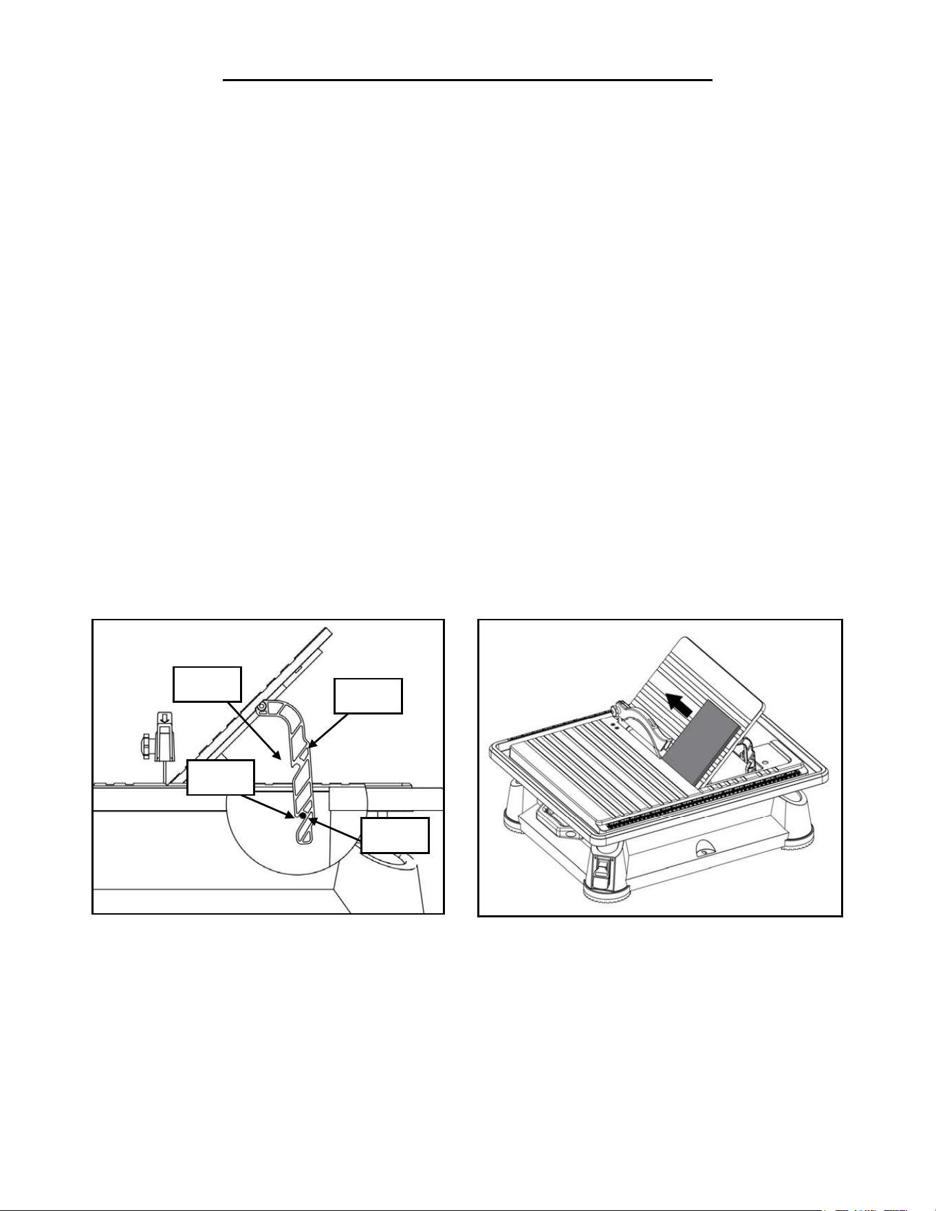
MAKING A BEVEL CUT (Fig. 17)
The bevel table can be set to 22.5° and 45° angles for bevel cuts. Internal or external bevel cuts can be made by turn-
ing the tile face up or face down.
1. Using a marker or grease pencil, mark the line of cut on the tile.
2. Remove the rip guide.
3. Tilt the bevel table. Set the bevel table to 22.5°or 45° by locating the two locking pins into the corresponding po-
sitioning grooves (Fig. 17). Make sure bevel table is locked firmly in place before beginning cut.
4. Place the tile on the table and firmly against the inner edge of the bevel table. Make sure the material is clear of
the cutting wheel before turning on the saw.
5. Turn the power switch to the ON position. Let the cutting wheel build up to full speed and wait for the wheel to
get wet feeding the material into the cutting wheel.
6. Hold the material firmly against the inner edge of the bevel table and feed the material into the cutting wheel in
a smooth motion (Fig. 14). Hold down on the edges of the tile to prevent the tile from lifting during the cut.
7. When the cut is completed, turn the saw OFF. Wait for the cutting wheel to come to a complete stop before
removing any part of the tile.
Fig. 17 Fig. 18
18
WARNING: To prevent serious injury from accidental operation, make sure that the saw is turned off
and unplugged from power source before installation, cleaning and maintenance operations.
MAINTENANCE
CLEANING
1. After every use, unplug the saw and remove the guides and bevel table from the saw.
2. Using a clean cloth or soft brush, clean each piece thoroughly and remove any trapped debris.
3. Remove the water drain plug and empty waste water into a bucket. Do not allow the water to splash onto the
ground or around the machine.
4. Rinse the machine thoroughly. Do not allow water to enter the electronic parts. Discard the waste water in ac-
cordance with local regulations.
5. Dry off the tool.
WARNING: Avoid using solvents when cleaning plastic parts. Most plastics are susceptible to damage
from various types of commercial solvents. Do not at any time let brake fluids, gasoline, petroleum-based
products, penetrating oils, etc., come in contact with plastic parts. Chemicals can damage, weaken or de-
stroy plastic which may result in serious personal injury.
LUBRICATION
All of the bearings in this tool are lubricated with a sufficient amount of high grade lubricant for the life of the unit
under normal operating conditions.
CUTTING WHEEL
1. Keep cutting wheels in good condition. Worn wheels or wheels in poor condition should be replaced before
operation. Replacement cutting wheels can be purchased from wenproducts.com by searching the part number
71707B.
2. Apart from installing and replacing the diamond wheels, there are no other user serviceable parts inside this tile
saw. Repairs and replacements should only be performed by authorized personnel.
STORAGE
Store the unit and accessories in a dark, dry, frost-free and well ventilated place, out of the reach of children. The
ideal storage temperature is between 40 to 86°F (5 and 30°C).
PRODUCT DISPOSAL
Used power tools should not be disposed of together with household waste. This product contains electronic com-
ponents that should be recycled. Please take this product to your local recycling facility for responsible disposal and
to minimize its environmental impact.
19

TROUBLESHOOTING GUIDE
Problem Possible Cause Solution
Tool will not start
1. No power
2. Internal damage or wear (e.g.
carbon brushes or switch)
3. Yellow switch safety key not
installed
1. Check power cord, power plug, power out-
let and fuse. Any damage in the power supply
should be service only by a qualified technician.
2. Have a qualified technician service the tool.
3. Install the yellow safety key.
Motor runs, but cutting
wheel remains still
when subject to load
The arbor nut (Part No. 71707-055)
is loose
Check that the flange is seated correctly on both
sides of the blade and tighten the arbor nut.
Excessive vibration
1. Cutting wheel warped or
unbalanced
2. Cutting wheel fitted incorrectly
1. Replace the cutting wheel.
2. Fit the cutting wheel correctly according to
instructions on page 11.
Cutting wheel is
discolored
1. Insufficient cooling water
2. Lateral friction caused by cut
runout
1. Fill the water reservoir with water up to the
maximum fill line.
2. Guide the workpiece through the cutting
wheel slower.
WARNING: Stop using the tool immediately if any of the following problems occur or risk serious per-
sonal injury. Repairs and replacements should only be performed by authorized personnel. If you have
any questions, please contact our customer service at (800) 232-1195, M-F 8-5 CST.
20

LIMITED TWO YEAR WARRANTY
WEN Products is committed to build tools that are dependable for years. Our warranties are consistent with this
commitment and our dedication to quality.
LIMITED WARRANTY OF WEN CONSUMER POWER TOOLS PRODUCTS FOR HOME USE
GREAT LAKES TECHNOLOGIES, LLC (“Seller”) warrants to the original purchaser only, that all WEN con-
sumer power tools will be free from defects in material or workmanship for a period of two (2) years from date of
purchase. Ninety days for all WEN products, if the tool is used for professional use.
SELLER’S SOLE OBLIGATION AND YOUR EXCLUSIVE REMEDY under this Limited Warranty and, to
the extent permitted by law, any warranty or condition implied by law, shall be the repair or replacement of parts,
without charge, which are defective in material or workmanship and which have not been misused, carelessly
handled, or misrepaired by persons other than Seller or Authorized Service Center. To make a claim under this
Limited Warranty, you must make sure to keep a copy of your proof of purchase that clearly defines the Date of
Purchase (month and year) and the Place of Purchase. Place of purchase must be a direct vendor of Great Lakes
Technologies, LLC. Third party vendors such as garage sales, pawn shops, resale shops, or any other secondhand
merchant void the warranty included with this product. Contact [email protected] or 1-800-232-
1195 M-F 8-5 CST to make arrangements for repairs and transportation.
When returning a product for warranty service, the shipping charges must be prepaid by the purchaser. The prod-
uct must be shipped in its original container (or an equivalent), properly packed to withstand the hazards of ship-
ment. The product must be fully insured with a copy of the warranty card and/or the proof of purchase enclosed.
There must also be a description of the problem in order to help our repairs department diagnose and fix the
issue. Repairs will be made and the product will be returned and shipped back to the purchaser at no charge.
THIS LIMITED WARRANTY DOES NOT APPLY TO ACCESSORY ITEMS THAT WEAR OUT FROM
REGULAR USAGE OVER TIME INCLUDING BELTS, BRUSHES, BLADES, ETC.
ANY IMPLIED WARRANTIES SHALL BE LIMITED IN DURATION TO TWO (2) YEARS FROM
DATE OF PURCHASE. SOME STATES IN THE U.S., SOME CANADIAN PROVINCES DO NOT AL-
LOW LIMITATIONS ON HOW LONG AN IMPLIED WARRANTY LASTS, SO THE ABOVE LIMITA-
TION MAY NOT APPLY TO YOU.
IN NO EVENT SHALL SELLER BE LIABLE FOR ANY INCIDENTAL OR CONSEQUENTIAL DAM-
AGES (INCLUDING BUT NOT LIMITED TO LIABILITY FOR LOSS OF PROFITS) ARISING FROM
THE SALE OR USE OF THIS PRODUCT. SOME STATES IN THE U.S. AND SOME CANADIAN
PROVINCES DO NOT ALLOW THE EXCLUSION OR LIMITATION OF INCIDENTAL OR CON-
SEQUENTIAL DAMAGES, SO THE ABOVE LIMITATION OR EXCLUSION MAY NOT APPLY TO
YOU.
THIS LIMITED WARRANTY GIVES YOU SPECIFIC LEGAL RIGHTS, AND YOU MAY ALSO HAVE
OTHER RIGHTS WHICH VARY FROM STATE TO STATE IN THE U.S., PROVINCE TO PROVINCE
IN CANADA AND FROM COUNTRY TO COUNTRY.
THIS LIMITED WARRANTY APPLIES ONLY TO PORTABLE ELECTRIC TOOLS, BENCH POW-
ER TOOLS, OUTDOOR POWER EQUIPMENT AND PNEUMATIC TOOLS SOLD WITHIN THE
UNITED STATES OF AMERICA, CANADA AND THE COMMONWEALTH OF PUERTO RICO. FOR
WARRANTY COVERAGE WITHIN OTHER COUNTRIES, CONTACT THE WEN CUSTOMER SUP-
PORT LINE.
21
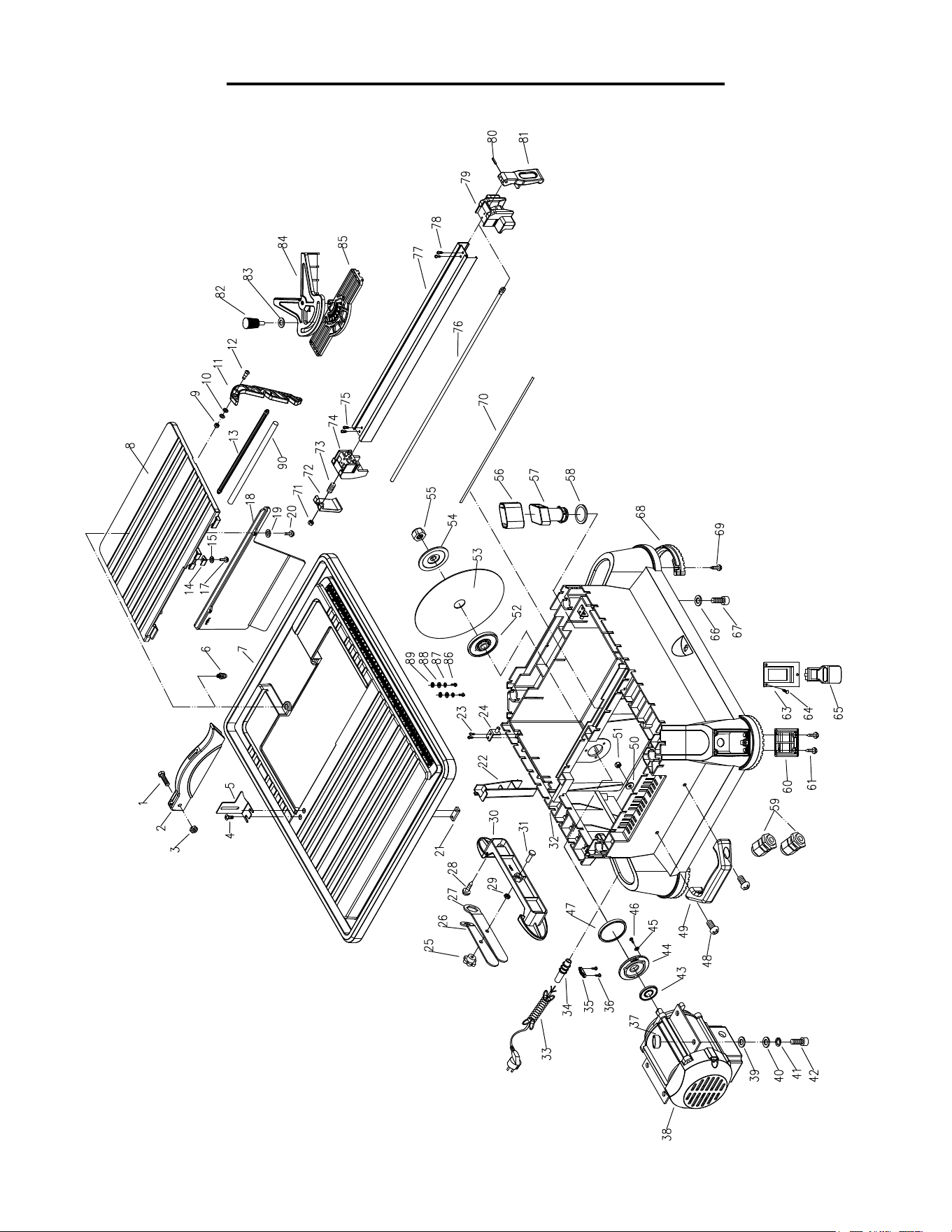
EXPLODED VIEW & PARTS LIST
22

EXPLODED VIEW & PARTS LIST
No. Part No. Description Qty.
1 71707-001
M6-10X25mm
Hex Head Bolt
1
2 71707-002 Blade Guard 1
3 71707-003 Knob 1
4 71707-004
M5-0.8X16mm
Flat Head Screw
2
5 71707-005 Blade Guard Bracket 1
6 71707-006 Rubber Pin 2
7 71707-007 Table 1
8 71707-008 Bevel Table 1
9 71707-009 M4-0.7mm Lock Nut 2
10 71707-010 4mm Serrated Washer 2
11 71707-011 Bevel Table Leg 2
12 71707-012 Screw 2
13 71707-013 Leg Connector 1
14 71707-014 Hook 1
15 71707-015 4mm Flat Washer 2
17 71707-017
M4-0.7X8mm
Pan Head Screw
2
18 71707-018 Baffle Plate 1
19 71707-019 4mm Flat Washer 3
20 71707-020
M4-0.7X8mm
Pan Head Screw
3
21 71707-021 Locking Plate 1
22 71707-022 Baffle 1
23 71707-023 Thread Forming Screw 4
24 71707-024 Leg Supporting Pin 2
25 71707-025 Knob 1
26 71707-026 Small Wrench 1
27 71707-027 Big Wrench 1
28 71707-028 Thread Forming Screw 4
29 71707-029 6mm Hex Nut 1
30 71707-030 Cord Storage 1
31 71707-031
M6-1.0X25mm
Pan Head Screw
1
32 71707-032 Base 1
33 71707-033 Power Cord 1
34 71707-034 Bushing 1
35 71707-035 Cord Clamp 1
36 71707-036 Thread Forming Screw 2
37 71707-037 Rubber Bushing 4
38 71707-038 Motor 1
39 71707-039 Rubber Washer 4
40 71707-040 8mm Flat Washer 4
41 71707-041 8mm Lock Washer 4
42 71707-042
M8-1.25X20mm
Socket Head Screw
4
43 71707-043 Rubber Ring 1
No. Part No. Description Qty.
44 71707-044 Seal Collar 1
45 71707-045 Flat Washer 3
46 71707-046 Thread Forming Screw 3
47 71707-047 O-Ring 1
48 71707-048
M6-1.0X20mm
Pan Head Screw
2
49 71707-049 Lifting Handle 1
50 71707-050 6mm Flat Washer 2
51 71707-051 6mm Lock Nut 2
52 71707-052 Inner Flange 1
53 71707B Cutting Wheel 1
54 71707-054 Outer Flange 1
55 71707-055 Arbor Nut 1
56 71707-056 Cap 1
57 71707-057 Overflow Drain 1
58 71707-058 O-Ring 1
59 71707-059 Strain Relief 2
60 71707-060 Cover 1
61 71707-061 Thread Forming Screw 4
63 71707-063 Switch Plate 1
64 71707-064 Thread Forming Screw 3
65 71707-065 Switch 1
66 71707-066 Flat Washer 4
67 71707-067 Socket Head Screw 4
68 71707-068 Foot 4
69 71707-069 Thread Forming Screw 12
70 71707-070 Seal Strip 1
71 71707-071 6mm Lock Nut 1
72 71707-072 Locking Plate 1
73 71707-073 Spring 1
74 71707-074 Back Support Block 1
75 71707-075 Thread Forming Screw 2
76 71707-076 Rod 1
77 71707-077 Rip Guide 1
78 71707-078 Thread Forming Screw 2
79 71707-079 Front Support Bracket 1
80 71707-080 Pin 1
81 71707-081 Locking Lever 1
82 71707-082 Knob 1
83 71707-083 Washer 1
84 71707-084 Miter Guide 1
85 71707-085 Miter Guide Sliding Base 1
86 71707-086
M4-0.7mmx10
Pan Head Screw
2
87 71707-087 4mm Lock Washer 2
88 71707-088 4mm Flat Washer 2
89 71707-089 4mm Serrated Washer 2
90 71707-090 Metal Sheath 1
23

THANKS FOR
REMEMBERING