
12-INCH
DISC SANDER
Instruction Manual
IMPORTANT: Your new tool has been engineered and manufactured to WEN’s highest standards for dependability,
ease of operation, and operator safety. When properly cared for, this product will supply you years of rugged,
trouble-free performance. Pay close attention to the rules for safe operation, warnings, and cautions. If you use
your tool properly and for its intended purpose, you will enjoy years of safe, reliable service.
NEED HELP? CONTACT US!
Have product questions? Need technical support? Please feel free to contact us:
TECHSUPPOR[email protected]
1-847-429-9263 (M-F 8AM-5PM CST)
For replacement parts and the most up-to-date instruction manuals, visit WENPRODUCTS.COM
MODEL 65812

CONTENTS
WELCOME 3
Introduction ..................................................................................................... 3
Specifications ................................................................................................... 3
SAFETY 4
General Safety Rules ........................................................................................ 4
Disc Sander Safety Warnings ........................................................................... 6
Electrical Information ....................................................................................... 7
BEFORE OPERATING 8
Unpacking & Packing List .................................................................................8
Know Your Disc Sander ................................................................................... 8
Assembly & Adjustment ................................................................................... 9
13
Operation ....................................................................................................... 13
Maintenance ................................................................................................... 15
Exploded View & Parts List .............................................................................16
Troubleshooting Guide ................................................................................... 18
Warranty Statement ....................................................................................... 19
OPERATION & MAINTENANCE
To purchase replacement parts or accessories for your tool, visit WENPRODUCTS.COM
Replacement Sanding Discs (Part No. 65812SD)
2

SPECIFICATIONS
Model Number 65812
Motor 120V, 60 Hz, 8A
No-Load Speed 1725 RPM
Disc Size 12 in.
Table Size 16-3/8 in. x 6-7/8 in.
Table Height 7-1/2 in.
Table Tilting (Bevel) Angle 45º Down
Miter Angle 60º Left & Right
Dust Port Size
Outer Diameter: 2 in.
Inner Diameter: 1-13/16 in.
Dust Hose Size
Outer Diameter: 2-1/2 in.
Inner Diameter: 2 in.
Product Dimensions 16-3/8 in. x 18-1/2 in. x 14-1/8 in.
Product Net Weight 60.1 Pounds
INTRODUCTION
Thanks for purchasing the WEN Disc Sander. We know you are excited to put your tool to work, but first, please
take a moment to read through the manual. Safe operation of this tool requires that you read and understand this
operator’s manual and all the labels affixed to the tool. This manual provides information regarding potential safety
concerns, as well as helpful assembly and operating instructions for your tool.
NOTE: The following safety information is not meant to cover all possible conditions and situations that may occur.
WEN reserves the right to change this product and specifications at any time without prior notice.
At WEN, we are continuously improving our products. If you find that your tool does not exactly match this manual,
please visit wenproducts.com for the most up-to-date manual or contact our customer service at 1-847-429-9263.
Keep this manual available to all users during the entire life of the tool and review it frequently to maximize
safety for both yourself and others.
Indicates danger, warning, or caution. The safety symbols and the explanations with them deserve your
careful attention and understanding. Always follow the safety precautions to reduce the risk of fire, electric shock
or personal injury. However, please note that these instructions and warnings are not substitutes for proper ac-
cident prevention measures.
3

GENERAL SAFETY RULES
WORK AREA SAFETY
1. Keep work area clean and well lit. Cluttered or dark
areas invite accidents.
2. Do not operate power tools in explosive atmo-
spheres, such as in the presence of flammable liquids,
gases or dust. Power tools create sparks which may ig-
nite the dust or fumes.
3. Keep children and bystanders away while operating
a power tool. Distractions can cause you to lose control.
ELECTRICAL SAFETY
1. Power tool plugs must match the outlet. Never mod-
ify the plug in any way. Do not use any adapter plugs
with earthed (grounded) power tools. Unmodified plugs
and matching outlets will reduce risk of electric shock.
2. Avoid body contact with earthed or grounded surfac-
es such as pipes, radiators, ranges and refrigerators.
There is an increased risk of electric shock if your body
is earthed or grounded.
3. Do not expose power tools to rain or wet conditions.
Water entering a power tool will increase the risk of elec-
tric shock.
4. Do not abuse the cord. Never use the cord for car-
rying, pulling or unplugging the power tool. Keep cord
away from heat, oil, sharp edges or moving parts.
Damaged or entangled cords increase the risk of electric
shock.
5. When operating a power tool outdoors, use an ex-
tension cord suitable for outdoor use. Use of a cord
suitable for outdoor use reduces the risk of electric
shock.
6. If operating a power tool in a damp location is un-
avoidable, use a ground fault circuit interrupter (GFCI)
protected supply. Use of a GFCI reduces the risk of elec-
tric shock.
PERSONAL SAFETY
1. Stay alert, watch what you are doing and use com-
mon sense when operating a power tool. Do not use a
power tool while you are tired or under the influence
of drugs, alcohol or medication. A moment of inatten-
tion while operating power tools may result in serious
personal injury.
2. Use personal protective equipment. Always wear
eye protection. Protective equipment such as a respira-
tory mask, non-skid safety shoes and hearing protection
used for appropriate conditions will reduce the risk of
personal injury.
3. Prevent unintentional starting. Ensure the switch is
in the off-position before connecting to power source
and/or battery pack, picking up or carrying the tool.
Carrying power tools with your finger on the switch or
energizing power tools that have the switch on invites
accidents.
4. Remove any adjusting key or wrench before turning
the power tool on. A wrench or a key left attached to a
rotating part of the power tool may result in personal
injury.
5. Do not overreach. Keep proper footing and balance
at all times. This enables better control of the power
tool in unexpected situations.
6. Dress properly. Do not wear loose clothing or jew-
elry. Keep your hair and clothing away from moving
parts. Loose clothes, jewelry or long hair can be caught
in moving parts.
Safety is a combination of common sense, staying alert and knowing how your item works. The term “power tool”
in the warnings refers to your mains-operated (corded) power tool or battery-operated (cordless) power tool.
SAVE THESE SAFETY INSTRUCTIONS.
WARNING! Read all safety warnings and all instructions. Failure to follow the warnings and instructions may
result in electric shock, fire and/or serious injury.
4

GENERAL SAFETY RULES
7. If devices are provided for the connection of dust
extraction and collection facilities, ensure these are
connected and properly used. Use of dust collection
can reduce dust-related hazards.
POWER TOOL USE AND CARE
1. Do not force the power tool. Use the correct power
tool for your application. The correct power tool will
do the job better and safer at the rate for which it was
designed.
2. Do not use the power tool if the switch does not turn
it on and off. Any power tool that cannot be controlled
with the switch is dangerous and must be repaired.
3. Disconnect the plug from the power source and/or
the battery pack from the power tool before making
any adjustments, changing accessories, or storing
power tools. Such preventive safety measures reduce
the risk of starting the power tool accidentally.
4. Store idle power tools out of the reach of children
and do not allow persons unfamiliar with the power
tool or these instructions to operate the power tool.
Power tools are dangerous in the hands of untrained us-
ers.
5. Maintain power tools. Check for misalignment or
binding of moving parts, breakage of parts and any
other condition that may affect the power tool’s opera-
tion. If damaged, have the power tool repaired before
use. Many accidents are caused by poorly maintained
power tools.
6. Keep cutting tools sharp and clean. Properly main-
tained cutting tools with sharp cutting edges are less
likely to bind and are easier to control.
7. Use the power tool, accessories and tool bits, etc.
in accordance with these instructions, taking into ac-
count the working conditions and the work to be per-
formed. Use of the power tool for operations different
from those intended could result in a hazardous situa-
tion.
8. Use clamps to secure your workpiece to a stable
surface. Holding a workpiece by hand or using your
body to support it may lead to loss of control.
9. KEEP GUARDS IN PLACE and in working order.
SERVICE
1. Have your power tool serviced by a qualified repair
person using only identical replacement parts. This
will ensure that the safety of the power tool is main-
tained.
CALIFORNIA PROPOSITION 65 WARNING
Some dust created by power sanding, sawing, grinding,
drilling, and other construction activities may contain
chemicals, including lead, known to the State of Califor-
nia to cause cancer, birth defects, or other reproductive
harm. Wash hands after handling. Some examples of
these chemicals are:
• Lead from lead-based paints.
• Crystalline silica from bricks, cement, and other
masonry products.
• Arsenic and chromium from chemically treated
lumber.
Your risk from these exposures varies depending on
how often you do this type of work. To reduce your ex-
posure to these chemicals, work in a well-ventilated area
with approved safety equipment such as dust masks
specially designed to filter out microscopic particles.
Safety is a combination of common sense, staying alert and knowing how your item works. The term “power tool”
in the warnings refers to your mains-operated (corded) power tool or battery-operated (cordless) power tool.
SAVE THESE SAFETY INSTRUCTIONS.
WARNING! Read all safety warnings and all instructions. Failure to follow the warnings and instructions may
result in electric shock, fire and/or serious injury.
5

DISC SANDER SAFETY
1. Tool Purpose. Your disc sander is intended for sand-
ing natural, solid woods and composite materials. Op-
erations for which the tool was not designed, including
modification of the machine, may cause machine dam-
age or personal injury, and invalidate the warranty.
2. Work Environment. Do not operate the tool in wet
or damp conditions; doing so significantly increases the
risk of electrical shock. Do not operate the tool in the
presence of flammable liquids or gases; sparks gener-
ated by the tool could ignite these flammable materials.
Keep the work area clean.
3. Securing the Tool. For operation safety, mount the
machine to a flat and secure work surface or stand.
4. Personal Safety. Tie back long hair. Do not wear
loose clothing or jewelry as they might get drawn in by
the tool. Always wear ANSI Z87.1-approved glasses with
side shields, hearing protection and a dust mask when
using the sander.
5. Do not wear gloves while operating this machine.
6. Dust Collection. Use of sanders can produce harm-
ful particles while sanding certain types of woods. Be
sure to wear a dust mask and connect the sander to an
adequate dust collection system.
7. Tool & Accessories inspection. Before operation,
check the tool and accessories for any damage or miss-
ing parts. Do not use the tool if any part is missing or
damaged. Make sure all adjustments are correct and all
connections are tight. Keep all guards in place.
8. Prevent Accidental Starting. Make sure the power
switch is in the OFF position prior to plugging in the
machine. Always make sure the power switch is in the
OFF position and the machine is unplugged when doing
any cleaning, assembly, setup operations, or when not
in use.
9. Keeps Hands Away. Keep your hands and all other
body parts away from the rotating sanding disc. Do not
attempt to stop the sanding disc with your hand. Keep
hands at a safety distance from the disc while sanding.
10. Sanding Disc. Use only 12-inch PSA adhesive-
backed sanding discs.. The use of any accessories or
attachments not recommended may cause injury to you
and damage your machine. Replace worn, folded or torn
discs. Replacement sanding discs can be purchased
from wenproducts.com by searching 65812SD.
11. Table Distance. Maintain a 1/16 inch clearance be-
tween the sanding disc and table to avoid trapping the
workpiece or fingers.
12. Supporting the Workpiece. Always support the
workpiece firmly on the worktable. Use the miter gauge
or suitable jigs when sanding small workpieces.
13. Turning off the Tool. After operation, switch off and
unplug the power cord. Allow the tool to stop completely
(takes about 4.5 minutes) before cleaning, changing ac-
cessories or making adjustments on the tool.
DISC SANDER SAFETY WARNINGS
WARNING! Do not operate the power tool until you have read and understood the following instructions and
the warning labels.
6
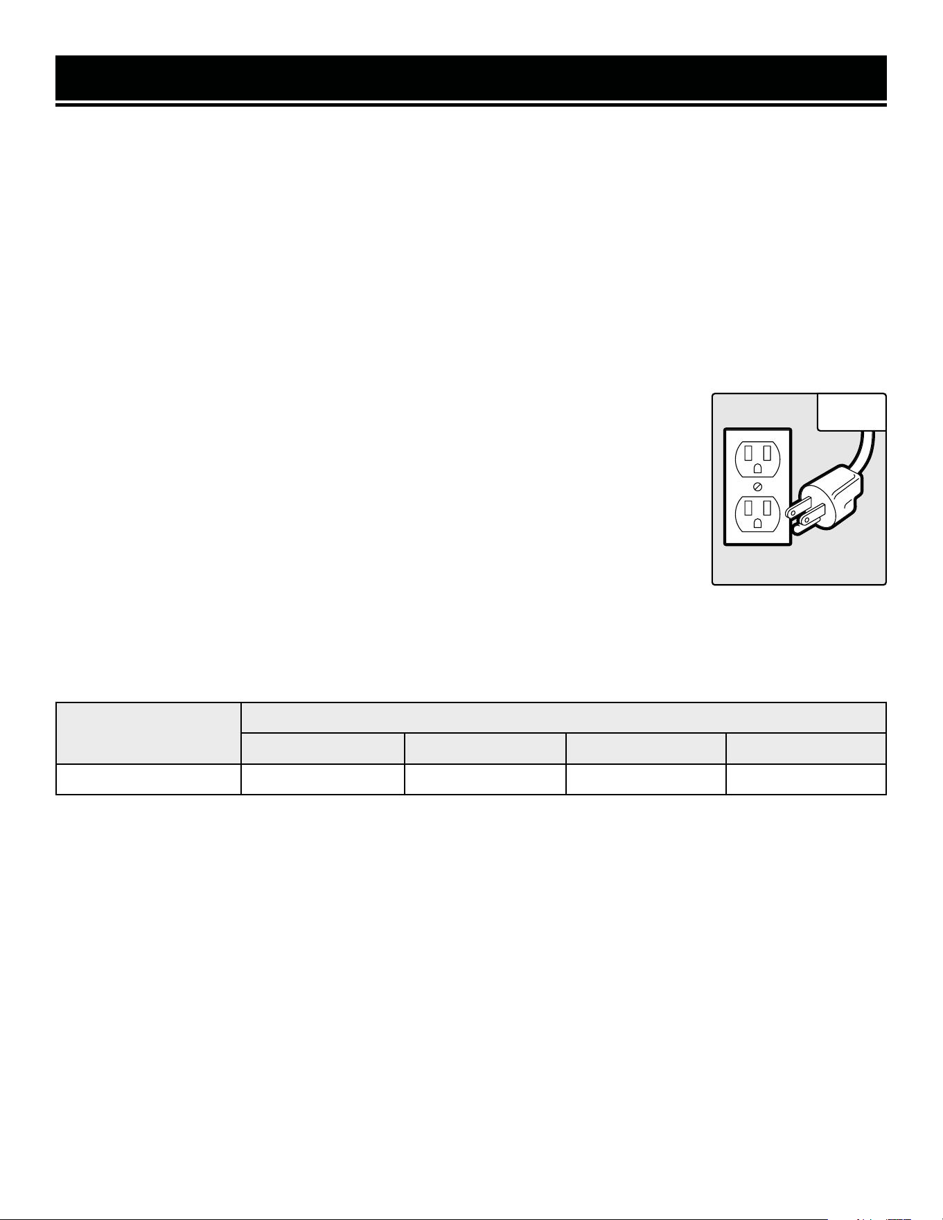
ELECTRICAL INFORMATION
AMPERAGE
REQUIRED GAUGE FOR EXTENSION CORDS
25 ft. 50 ft. 100 ft. 150 ft.
8A 18 gauge 16 gauge 16 gauge 14 gauge
3. Check with a licensed electrician or service personnel if you do not completely under-
stand the grounding instructions or whether the tool is properly grounded.
4. Use only three-wire extension cords that have three-pronged plugs and outlets that
accept the tool’s plug. Repair or replace a damaged or worn cord immediately.
CAUTION! In all cases, make certain the outlet in question is properly grounded. If you
are not sure, have a licensed electrician check the outlet.
GUIDELINES AND RECOMMENDATIONS FOR EXTENSION CORDS
When using an extension cord, be sure to use one heavy enough to carry the current your
GROUNDING INSTRUCTIONS
In the event of a malfunction or breakdown, grounding provides the path of least resistance for an electric current
and reduces the risk of electric shock. This tool is equipped with an electric cord that has an equipment grounding
conductor and a grounding plug. The plug MUST be plugged into a matching outlet that is properly installed and
grounded in accordance with ALL local codes and ordinances.
1. Do not modify the plug provided. If it will not fit the outlet, have the proper outlet installed by a licensed electri-
cian.
2. Improper connection of the equipment grounding conductor can result in electric shock. The conductor with the
green insulation (with or without yellow stripes) is the equipment grounding conductor. If repair or replacement of
the electric cord or plug is necessary, DO NOT connect the equipment grounding conductor to a live terminal.
1. Examine extension cord before use. Make sure your extension cord is properly wired and in good condition.
Always replace a damaged extension cord or have it repaired by a qualified person before using it.
2. Do not abuse extension cord. Do not pull on cord to disconnect from receptacle; always disconnect by pulling on
plug. Disconnect the extension cord from the receptacle before disconnecting the product from the extension cord.
Protect your extension cords from sharp objects, excessive heat and damp/wet areas.
3. Use a separate electrical circuit for your tool. This circuit must not be less than a 12-gauge wire and should be
protected with a 15A time-delayed fuse. Before connecting the motor to the power line, make sure the switch is in
the OFF position and the electric current is rated the same as the current stamped on the motor nameplate. Running
at a lower voltage will damage the motor.
product will draw. An undersized cord will cause a drop in line voltage resulting in loss of power and overheating.
The table below shows the correct size to be used according to cord length and ampere rating. When in doubt, use
a heavier cord. The smaller the gauge number, the heavier the cord.
Fig. 1
7
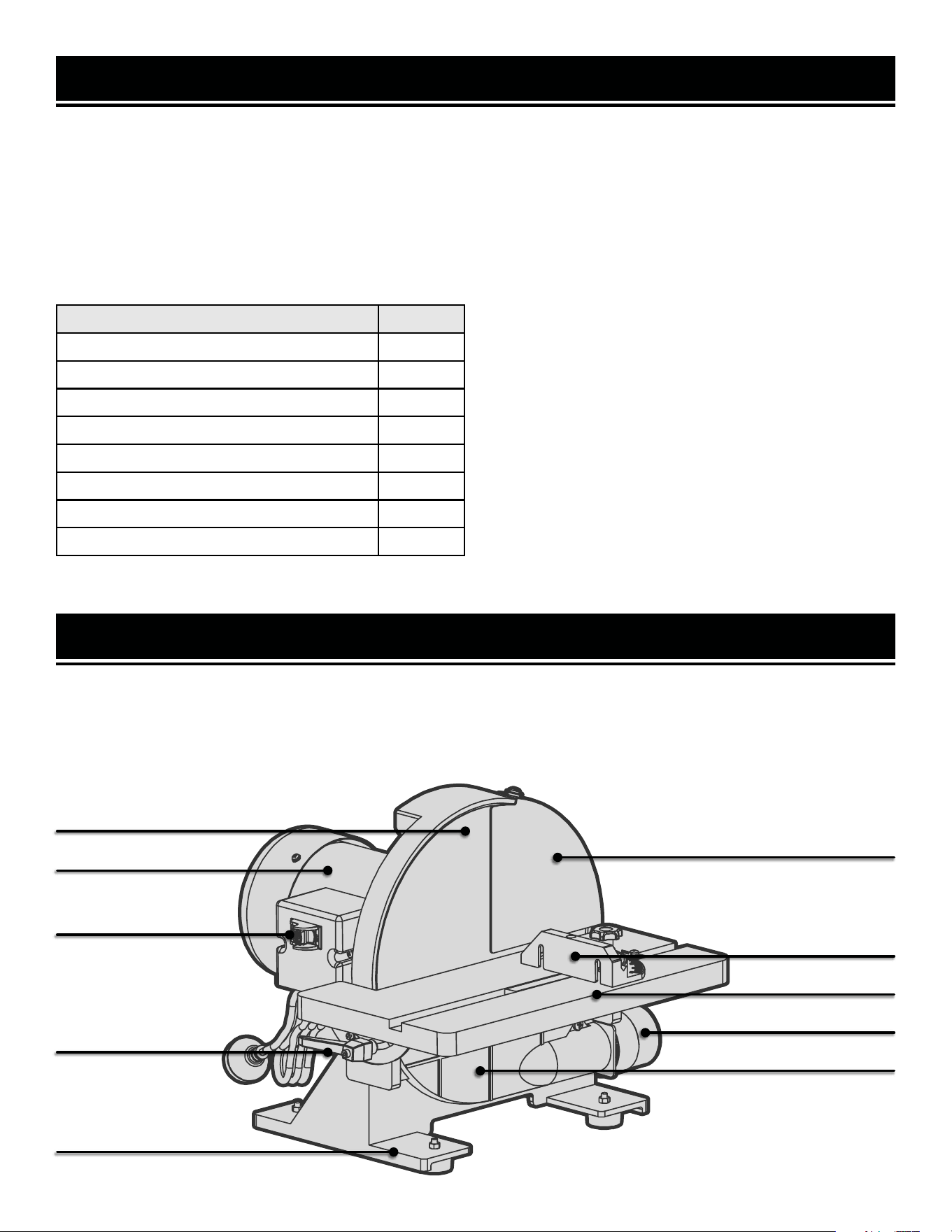
KNOW YOUR DISC SANDER
TOOL PURPOSE
Sand, smooth, and remove jagged edges with your WEN Disc Sander. Refer to the following diagrams to become
familiarized with all the parts and controls of your disc sander. The components will be referred to later in the manual
for assembly and operation instructions.
Disc Guard
UNPACKING & PACKING LIST
UNPACKING
With the help of a friend or trustworthy foe, such as one of your in-laws, carefully remove the disc sander from the
packaging and place it on a sturdy, flat surface. Make sure to take out all contents and accessories. Do not discard
the packaging until everything is removed. Check the packing list below to make sure you have all of the parts and
accessories. If any part is missing or broken, please contact customer service at 1-847-429-9263 (M-F 8-5 CST),
or email [email protected].
PACKING LIST
Description Qty.
Sander 1
*60-Grit Sanding Disc 1
Work Table 1
Pivot Indexing Pin 2
Bevel Locking Handle with Washer 2
Miter Gauge 1
Dust Hose 1
3mm Hex Wrench 1
CLEANING THE SURFACES
1. Your tool comes protected with a layer of anti-rust
coating. Clean all rust protected surfaces using a soft
cloth, moistened with kerosene. Do not use gasoline, or
cellulose-based solvents such as paint thinner or lac-
quer thinner, as these will damage the painted surfaces.
2. Apply a coat of paste wax to the table to prevent rust.
Wipe all parts thoroughly with a clean, dry cloth.
* Pre-installed on the unit.
Miter Gauge
Work Table
Dust Cover
Dust Port
Base
Bevel Lock
Power Switch
and Safety Key
Motor
Sanding Disc (60-Grit)
8
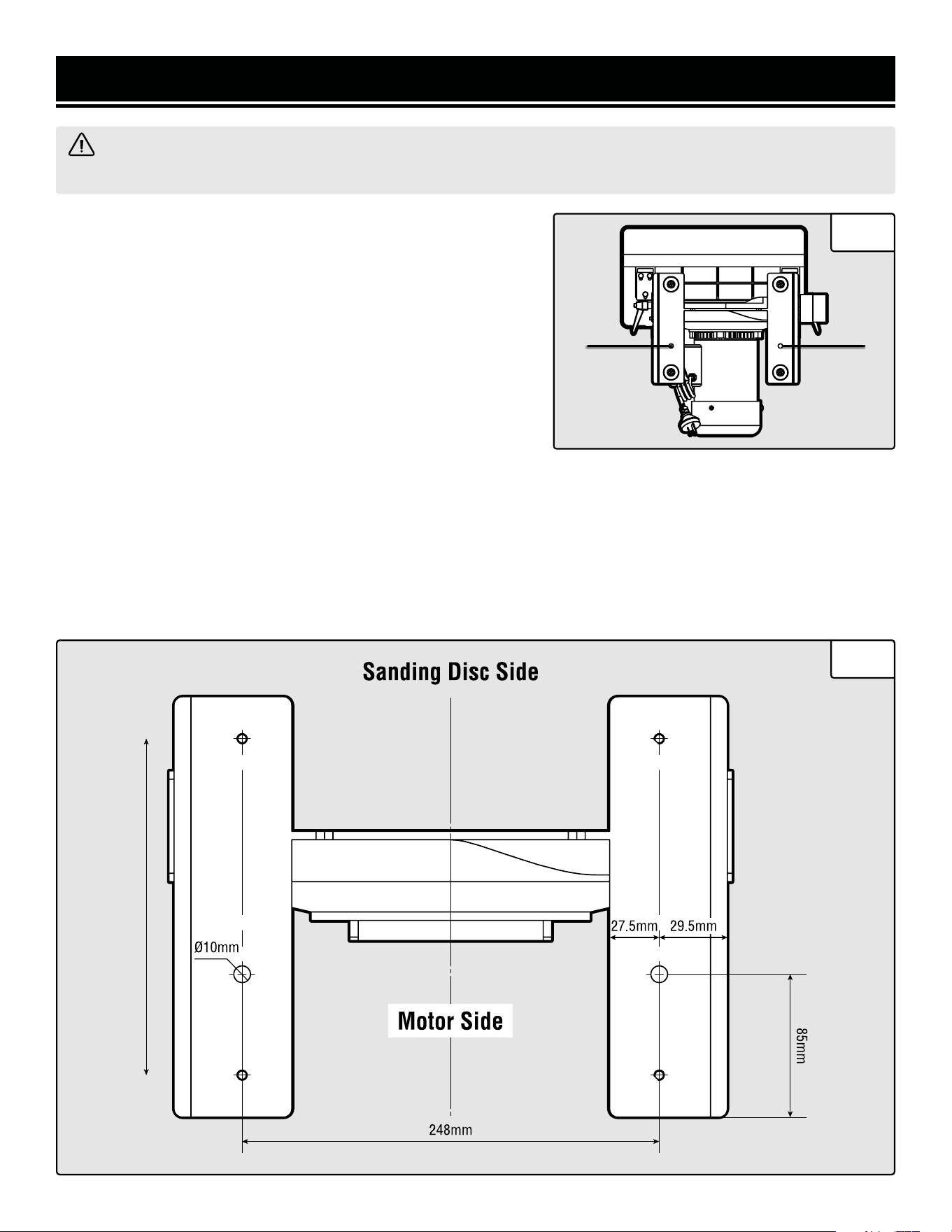
SECURING SANDER TO A WORKBENCH
For safe operation, the machine must be secured onto a flat, se-
cure workbench or stand. Refer to the base dimensions shown in
Fig. 2. For temporary mounting, attach a large C-Clamp to each
side of the sander and the workbench. For permanent mounting,
follow the instructions below:
1. Place the sander on a stable workbench.
2. A mounting hole (Fig. 1 - 1) is located on each leg towards the
rear of the sander body. Insert a pencil through the two mounting
holes and mark the hole locations on the workbench.
ASSEMBLY & ADJUSTMENTS
WARNING! To prevent serious injury from accidental operation, make sure the power cord is disconnected
from the power source and the tool is turned OFF before assembly or making any adjustments.
Fig. 1
3. Remove sander. Drill two 3/8” holes through the workbench.
4. Align the sander base over the mounting holes and secure it using two 5/16” screws and washers, locking wash-
ers, and hex nuts (mounting hardware not included).
NOTE: Your sander is compatible with the WEN 6588T and MSA658T Multipurpose Planer Stand, available at
wenproducts.com. Forget measuring and drilling holes on your workbench, simply mount your machine onto the
mobile stand with pre-drilled holes, and transport your machine around the workshop with ease.
Fig. 2
1 1
9
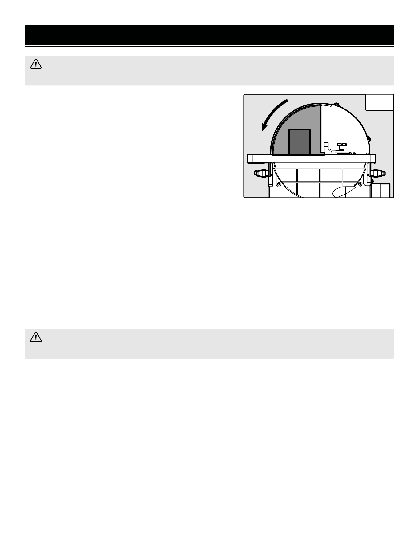
INSTALLING / CHANGING THE SANDING DISC
Your sander comes with a 60-Grit PSA (pressure sensitive adhesive) sanding disc. This is a coarse sanding disc that
is good for quick stock removal. For finish sanding, you will need a finer-grit sanding disc. Additional sanding discs
can be purchased from wenproducts.com by searching 65812SD. Follow the steps below to replace a sanding disc:
NOTE: Only 12-inch sanding discs with pressure sensitive adhesive (PSA) can be used. Hook & loop sanding discs
or sanding discs of different size cannot be used on this sander.
1. Remove the disc guard and dust cover to expose the sanding disc plate.
2. Peel the used sanding disc from the metal disc plate. TIP: A putty knife, dryer, or heat gun may help with this
process.
3. Wipe clean the disc plate to make sure it is clean of any residue. You can use mineral spirits to soften the PSA
adhesives to remove any residue from the plate. Rotate the disc by hand to get access to all of the disc surface.
4. Peel the protective backing from the new PSA 12-inch sanding disc. Align the sanding disc with the plate, and
press the disc firmly onto the plate, leaving no loose edges.
5. Re-install the disc guard on the right side of the sanding disc, and secure with the Phillips head screws and wash-
ers. Re-install the dust cover against the bottom of the disc, and fasten with the Phillips head screws.
NOTE: It is important to install the disc guard, as it prevents you from sanding on the wrong side of the disc. ONLY
sand on the left side of the disc, where the disc is rotating downwards (toward the table).
ASSEMBLY & ADJUSTMENTS
WARNING! To prevent serious injury from accidental operation, make sure the power cord is disconnected
from the power source and the tool is turned OFF before assembly or making any adjustments.
Fig. 3
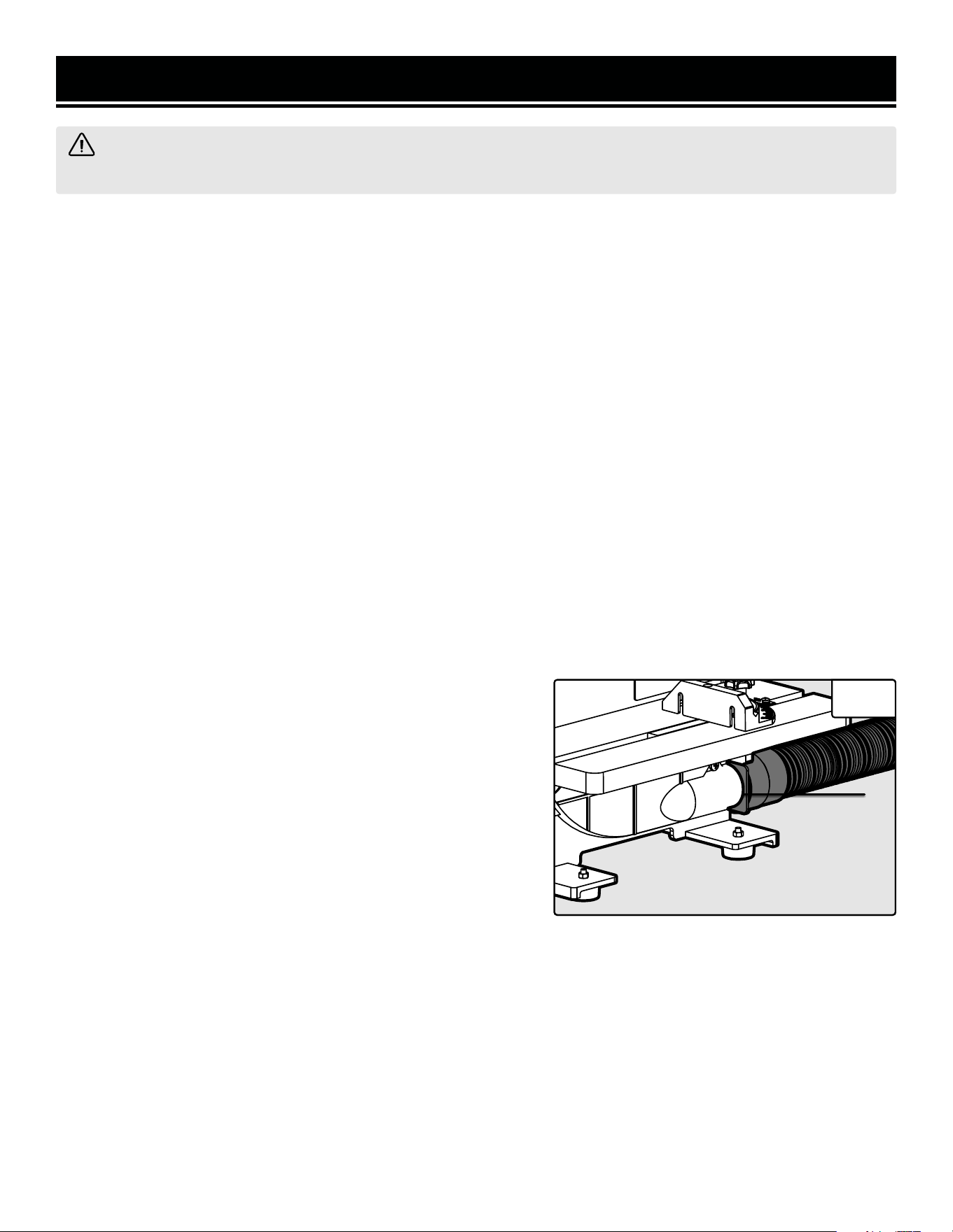
USING DUST COLLECTION
Sanding operations are dusty and can produce particles that are
harmful to your health. Always wear a dust mask and use an ad-
equate dust collection system.
Connect the included dust hose to the sander’s dust port (Fig.
3 - 1), and connect the other end to the dust collection system of
your choice. A dust port adapter may be needed (not included),
depending on the inlet size of your dust extractor.
1
10
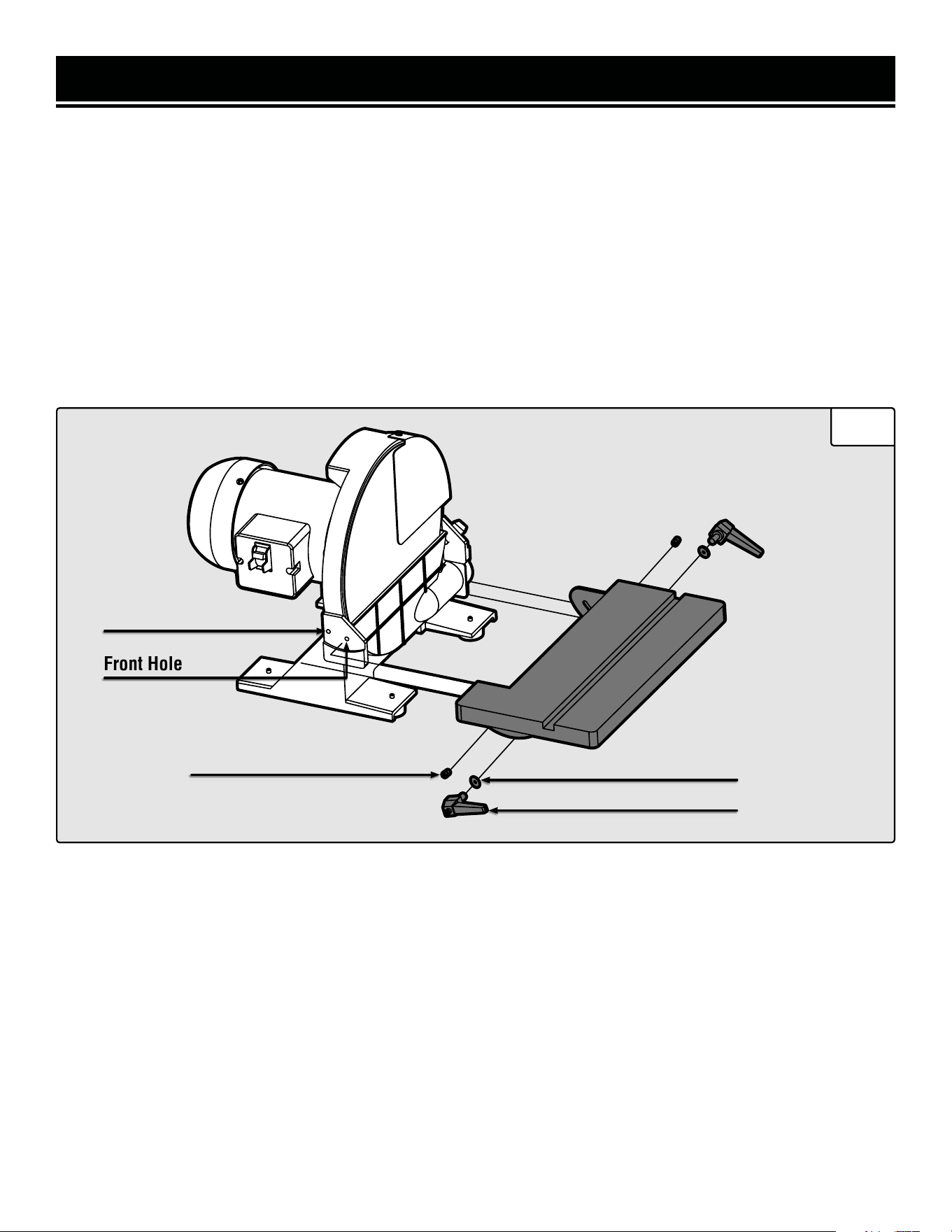
WORK TABLE ASSEMBLY
1. Holding the table flat, slide it onto the base frame.
2. Thread the pivot indexing pin fully into the pivot hole, through the scale plate. The scale plate should ride along
the outside of the indexing pin head.
3. Insert the bevel locking handle through the flat washer, the scale plate and into the front hole on each side of the
base frame.
NOTE: The bevel locking handles are threaded and spring-loaded. Pull out the handle to re-position it. Push in the
handle and rotate it to tighten or loosen the table. After tightening the handle, re-position it so that the handle is
pointing downwards, to prevent it from interfering with the work table .
4. Follow the instructions on the next page to properly adjust the work table and miter gauge.
ASSEMBLY & ADJUSTMENTS
Fig. 4
Pivot Indexing Screw
Bevel Locking Knob
Washer
Pivot Hole
Front Hole
11
ASSEMBLY & ADJUSTMENTS
WARNING! To prevent serious injury from accidental operation, make sure the power cord is disconnected
from the power source and the tool is turned OFF before assembly or making any adjustments.
Fig. 5
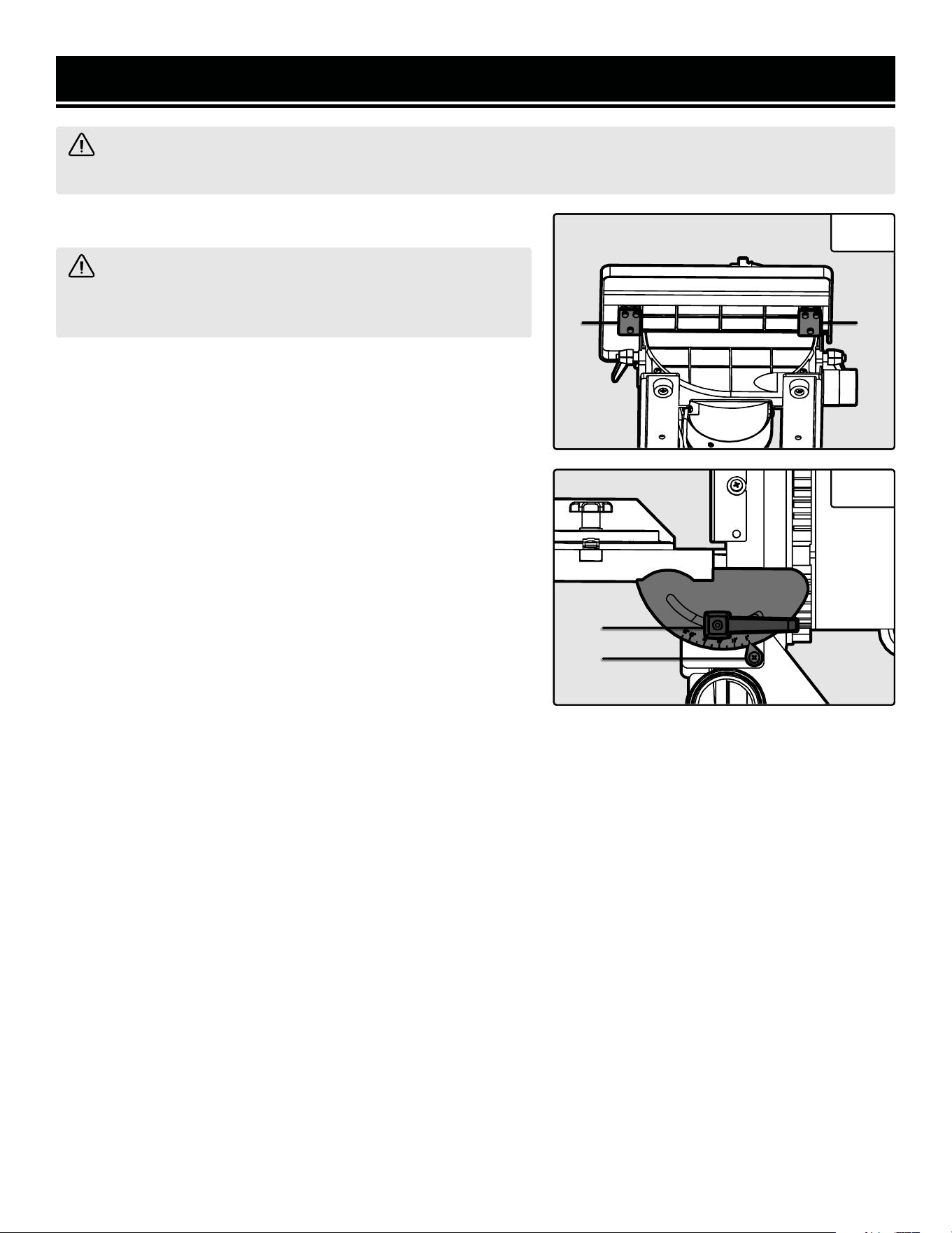
SETTING THE TABLE DISTANCE
1
WARNING! To avoid trapping the workpiece or fingers be-
tween the table and the sanding disc, the table edge should be
set at about 1/16 inch away from the sanding disc.
1. You can check the table distance with a 1/16” drill bit:
Try to insert the bit between the table and the disc. It should barely
fit into the space. If adjustment is needed, follow the instructions
below.
2. Loosen the six hex bolts under the table support brackets (Fig.
5 - 1).
3. Using the 1/16” drill bit as a spacer, place it between the sand-
ing disc and the inner edge of the table. Move the table into posi-
tion against the drill bit.
4. Hold the table in place and tighten the six hex bolts.
5. Remove the drill bit.
SQUARING THE TABLE
To ensure accurate end sanding, the work table must be square
to the sanding surface prior to operation. Follow the steps below
to make sure your table is square with the sanding disc at the 0°
setting.
1. Loosen the two bevel locking handles (Fig. 6 - 1) and slide the
table into the 0° position indicated on the bevel scale (Fig. 6 - 2).
Tighten the two locking handles.
2. Place a square against the sanding disc and the table. Check if
the surface of the table is square to the disc.
3. If adjustment is needed, loosen the two bevel locking handles
and slide the table against the edge of the square so that it is
perpendicular to the sanding disc. Tighten the two bevel locking
handles.
4. Using a Phillips head screw driver, loosen the screw securing
the bevel pointer and adjust it to point to 0° on the bevel scale.
Tighten the Phillips head screw.
5. Recheck the square.
Fig. 6
12
1
1
2
SQUARING THE MITER GAUGE
The miter gauge included with your sander attaches onto the work table to provide support for your workpiece and
help you sand at the desired miter angle. It is recommended to use the miter gauge to support small workpieces.
The miter gauge can be set anywhere from 0° to 60° (right or left). To check and adjust the squaring of the miter
gauge:
1. Loosen the miter lock knob, and set the miter gauge to 0° (indicated on the miter scale).
2. Place a square against the sanding disc and the flat face of the miter gauge. Check if the miter gauge face is 90°
to the sanding surface.
3. If adjustment is needed, loosen the miter lock knob and slide the miter gauge so that it is perpendicular to the
sanding disc. Tighten the miter lock knob.
4. Using a Phillips head screw driver, loosen the screw securing the miter point and adjust it to point to 0° on the
miter scale. Tighten the Phillips head screw.
5. Recheck the square.
ASSEMBLY & ADJUSTMENTS
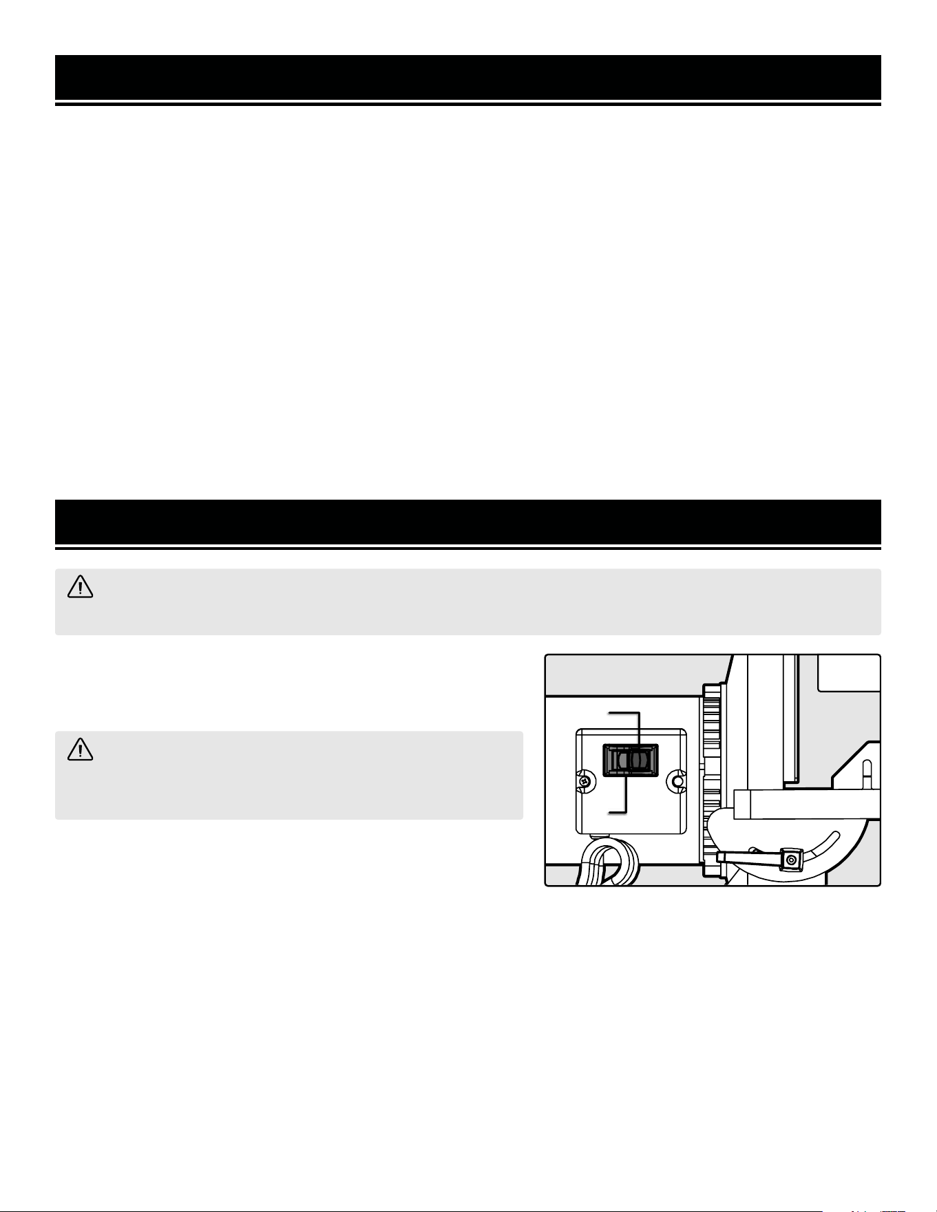
ON/OFF SWITCH WITH SAFETY KEY
The power switch includes a safety key to prevent unauthorized
use of the sander to increase safety.
OPERATION
WARNING! Do not operate this tool until all parts have been properly assembled. To prevent serious injury,
make sure all the warnings and instructions have been read and understood before operation.
WARNING! Remove the safety key whenever the sander
is not in use. Place the key in a safe place and out of the reach
of children.
1. To turn the sander ON, insert the safety key (Fig. 7 - 1) into the
key slot in the center of the ON / OFF switch (Fig. 7 - 2). Push the
switch to the ON position to start the sander.
2. To turn the sander OFF, push switch to the OFF position and re-
move the safety key. The sander may take a few minutes to come
to a complete stop.
Fig. 7
13
1
2
SANDING OPERATION
Your disc sander is designed for sanding outside edges and the
ends of workpieces. The sanding disc rotates counterclockwise,
so you should ONLY work on the left side of the disc, where the
disc applies downward pressure on the workpiece against the
table. Sanding on the wrong side of the disc will cause the work-
piece to fly up and cause injuries.
1. Turn ON the sander. It will take a few seconds for the disc to
reach full speed.
2. Hold the workpiece down firmly against the table. Carefully
feed the workpiece into the left side of the disc. Move workpiece
back and forth against the sanding disc; do not hold workpiece in
one place for too long to avoid burning the work surface. Do not
use excessive pressure to prevent overloading the sander.
OPERATION
WARNING! Do not operate this tool until all parts have been properly assembled. To prevent serious injury,
make sure all the warnings and instructions have been read and understood before operation.
Fig. 8
NOTE: When sanding small workpieces, make sure to use proper support, such as the included miter gauge or other
jigs. Small workpieces must be adequately supported, otherwise they may fly out and cause injuries.
3. When the sanding operation is finished, turn off the sander and remove the safety key. It may take a few minutes
for the disc to stop. DO NOT touch the sanding disc while it is still rotating.
BEVEL SANDING
The worktable can be tilted for bevel sanding. Loosen the two locking handles, and tilt the worktable to the desired
angle as indicated on the bevel gauge. Re-tighten the table locking handles.
WARNING! To avoid jamming fingers or workpiece between the table and sanding surface, the table should
maintain a maximum of 1/16” distance from the sanding disc. Check and reposition the table as necessary.
14

GENERAL MAINTENANCE
1. Before each use, inspect the general condition of the tool.
Check for:
• Loose hardware,
• Misalignment or binding of moving parts,
• Damaged cord/electrical wiring,
• Cracked or broken parts, and
• Any other condition that may affect its safe operation.
2. After every operation, use a vacuum to remove sanding dust and chips from the tool and work area. Wipe the tool
clean with a soft cloth. Make sure water does not get into the tool.
CAUTION: Most plastics are susceptible to damage from various types of commercial solvents. Do not use any
solvents or cleaning products that could damage the plastic parts. Some of these include but are not limited to:
gasoline, carbon tetrachloride, chlorinated cleaning solvents, and household detergents that contain ammonia.
3. Keep the ventilation openings free from dust and debris to prevent the motor from overheating.
4. Store the tool in a clean and dry place away from the reach of children.
5. Store sanding discs away from extremely hot/dry temperatures. Be careful not to fold or tear the sanding disc.
PRODUCT DISPOSAL
Used power tools should not be disposed of together with household waste. This product contains electronic com-
ponents that should be recycled. Please take this product to your local recycling facility for responsible disposal and
to minimize its environmental impact.
MAINTENANCE
WARNING! To avoid accidents, make sure the power switch is in the OFF position and unplug the tool from
the electrical outlet before cleaning or performing any maintenance. Servicing of the tool must be performed by
a qualified technician.
15
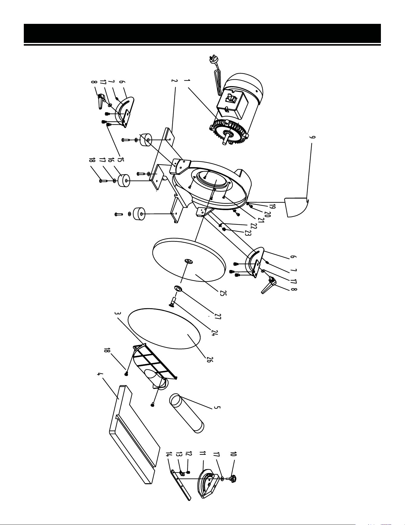
EXPLODED VIEW & PARTS LIST
16

No. Model No. Description Qty
1 65812-001 Motor Assembly 1
2 65812-002 Base 1
3 65812-003 Dust Cover 1
4 65812-004 Work Table 1
5 65812-005 Hose Assembly 1
6 65812-006 Scale Plate 2
7 65812-007 Locating Pin 2
8 65812-008 Bevel Locking Knob 2
9 65812-009 Disc Guard 1
10 65812-010 Miter Gauge Knob 1
11 65812-011 Miter Gauge 1
12 65812-012 Screw M5x8 1
13 65812-013 Miter Gauge Pointer 1
14 65812-014 Miter Rod 1
15 65812-015 Hex Bolt M6x10 6
16 65812-016 Rubber Feet 4
17 65812-017 Big Flat Washer D6 7
18 65812-018 Screw M6x20 6
19 65812-019 Rubber Washer 2
20 65812-020 Screw M5x8 2
21 65812-021 Hex Bolt M8x25 4
22 65812-022 Bevel Scale Plate Pointer 1
23 65812-023 Screw M4x8 1
24 65812-024 Screw M6x20 1
25 65812-025 Disc Plate 1
26 65812SD60 60-Grit Sanding Disc 1
27 65812-027 Sander Washer 1
EXPLODED VIEW & PARTS LIST
17

PROBLEM POSSIBLE CAUSE SOLUTION
Motor will not start
1. Power cord or extension cord damaged or
power plug not properly plugged in.
2. Safety key removed from power switch.
3. Defective power switch, defective motor,
short circuit in motor or loose connections.
1. Check the power cord, extension cord, power plug
and the power outlet. Do not use if any part is dam-
aged.
2. Insert the safety key into the power switch.
3. Stop using the tool and contact customer service at
1-847-429-9263, M-F 8-5 CST for assistance.
Motor overheats
1. Motor overloaded.
2. Extension cord too long or with an insuf-
ficient gauge.
1. Reduce load on the motor by reducing sanding
pressure on the workpiece.
2. Use an extension cord of appropriate gauge and
length or plug tool directly into the outlet.
Workpiece gets
pulled out of hands
1. Workpiece not properly supported.
2. Sanding workpiece too small.
1. Hold down the workpiece firmly against the work
table. Use the miter gauge to support the workpiece.
2. Hold small workpieces against miter gauge. Use a
jig to grasp or hold the workpiece.
Workpiece lifts up
from the
sanding disc
1. Sanding on the “up” side of the wheel.
1. Make sure the disc guard is installed. Sand on left
side of sanding disc (as operator faces the disc).
Burns on
workpiece
1. Too much pressure.
2. Work held still for too long.
3. Sanding grit too fine.
1. Reduce sanding pressure on the workpiece.
2. Move workpiece back and forth against the sanding
disc. Do not keep workpiece in one place for too long.
3. Use a coarser-grit sanding disc.
Sanding grains
easily rub off sand-
ing disc
1. Sanding disc has been damaged or folded.
2. Sanding disc has been stored in an incor-
rect environment.
1. Do not fold sanding disc. Replace with folded disc
with new sanding disc.
2. Store sanding accessories away from extremely
hot/dry temperatures.
Deep sanding
grooves or scars in
workpiece
1. Sanding disc grit is too coarse for the de-
sired finish.
2. Too much sanding force on workpiece.
3. Workpiece is held still against the disc for
too long.
4. Workpiece is sanded across the grain of the
wood.
1. Use a finer-grit sanding disc.
2. Reduce pressure on workpiece while sanding.
3. Keep workpiece moving while sanding.
4. Sand with the grain of the wood.
Sanding surface
clogs quickly
1. Too much pressure against sanding disc.
2. Sanding softwood.
1. Reduce pressure on workpiece while sanding.
2. Softwood clogs sandpaper easily. Clean or replace
sanding disc frequently.
TROUBLESHOOTING GUIDE
WARNING! Stop using the tool immediately if any of the following problems occur or risk serious personal
injury. If you have any questions, please contact customer service at 1-847-429-9263 (M-F 8-5 CST), or email
18

WARRANTY STATEMENT
WEN Products is committed to building tools that are dependable for years. Our warranties are consistent with this
commitment and our dedication to qualit
y.
LIMITED WARRANTY OF WEN PRODUCTS FOR HOME USE
GRE
AT LAKES TECHNOLOGIES, LLC (“Seller”) warrants to the original purchaser only, that all WEN
consumer
power tools will be free from defects in material or workmanship during personal use for a period of two (2) years
used
for professional or commercial use. Purchaser has 30 days from the date of purchase to report missing or
damaged parts.
SELLER’S
SOLE OBLIGATION AND YOUR EXCLUSIVE REMEDY under this Limited Warranty and, to the extent per-
mitted
by law, any warranty or condition implied by law, shall be the replacement of parts, without charge, which a
re
defective
in material or workmanship and which have not been subjected to misuse, alteration, careless handling,
misrepair
, abuse, neglect, normal wear and tear,
improper maintenance, or other conditions adversely affecting the
Product
or the component of the Product, whether by accident or intentionally, by persons other than Seller. To
make
a claim under this Limited Warranty, you must make sure to keep a copy of your proof of purchase that
clearly
-
dor
of Great Lakes Technologies, LLC. Purchasing through third party vendors, including but not limited to garage
sales,
pawn shops, resale shops, or any other secondhand merchant, voids the warranty included with this
product.
Contact [email protected] or 1-847-429-9263 with the following information to make arrangements:
your
shipping address, phone number, serial number, required part numbers, and proof of purchase. Damaged
or
defective parts and products may need to be sent to WEN before the replacements can be shipped out.
-
turning
a product for warranty service, the shipping charges must be prepaid by the purchaser. The product
must
be
shipped in its original container (or an equivalent), properly packed to withstand the hazards of shipment. The
product
must be fully insured with a copy of the proof of purchase enclosed. There must also be a description of
the
will be returned and shipped back to the pur
chaser at no charge for addresses within the contiguous United States.
THIS
LIMITED WARRANTY DOES NOT APPLY TO ITEMS THAT WEAR OUT FROM REGULAR USAGE OVER TIME,
INCLUDING
BELTS, BRUSHES, BLADES, BATTERIES, ETC. ANY IMPLIED WARRANTIES SHALL BE LIMITED IN
DUR
ATION TO TWO (2) YEARS FROM DATE OF PURCHASE. SOME STATES IN THE U.S. AND SOME CANADIAN
PROVINCES
DO NOT ALLOW LIMITATIONS ON HOW LONG AN IMPLIED WARRANTY LASTS, SO THE ABOVE LIMI-
TAT
ION MAY NOT APPLY TO YOU.
IN
NO EVENT SHALL SELLER BE LIABLE FOR ANY INCIDENTAL OR CONSEQUENTIAL DAMAGES (INCLUDING
BUT
NOT LIMITED TO LIABILITY FOR LOSS OF PROFITS) ARISING FROM THE SALE OR USE OF THIS PRODUCT.
SOME ST
ATES IN THE U.S. AND SOME CANADIAN PROVINCES DO NOT ALLOW THE EXCLUSION OR LIMITAT
ION
OF
INCIDENTAL OR CONSEQUENTIAL DAMAGES, SO THE ABOVE LIMITATION OR EXCLUSION MAY NOT APPLY
TO YOU.
THIS
LIMITED WARRANTY GIVES YOU SPECIFIC LEGAL RIGHTS, AND YOU MAY ALSO HAVE OTHER RIGHTS
WHICH
VARY FROM STATE TO STATE IN THE U.S., PROVINCE TO PROVINCE IN CANADA AND FROM COUNTRY
TO COUNT
RY.
THIS
LIMITED WARRANTY APPLIES ONLY TO ITEMS SOLD WITHIN THE UNITED STATES OF AMERICA, CANA-
DA
AND THE COMMONWEALTH OF PUERTO RICO. FOR WARRANTY COVERAGE WITHIN OTHER
COUNTRIES,
CONT
ACT THE WEN CUSTOMER SUPPORT LINE. FOR WARRANTY PARTS OR PRODUCTS REPAIRED UNDER
W
ARRANTY SHIPPING TO ADDRESSES OUTSIDE OF THE CONTIGUOUS UNITED STATES, ADDITIONAL
SHIPPING
CHARGES MAY APPLY.
19

V. 2022.11.11
THANKS FOR
REMEMBERING