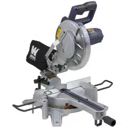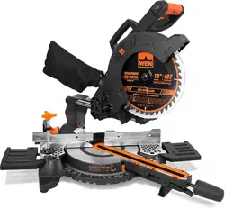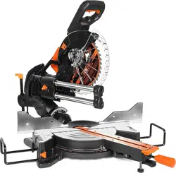
Model # 70730
10˝ DUAL SPEED
SLIDING COMPOUND
MITER SAW
bit.ly/wenvideo
Your new tool has been engineered and manufactured to WEN’s highest standards for dependability,
ease of operation, and operator safety. When properly cared for, this product will supply you years
of rugged, trouble-free performance. Pay close attention to the rules for safe operation, warnings,
and cautions. If you use your tool properly and for intended purpose, you will enjoy years of safe,
reliable service.
IMPORTANT:
NEED HELP? CONTACT US!
Have product questions? Need technical support?
Please feel free to contact us at:
800-232-1195
WENPRODUCTS.COM
(M-F 8AM-5PM CST)
For replacement parts visit
WENPRODUCTS.COM
LISTED
E493385

70730
120 V, 60 Hz, 15A
Speed 1: 2000 RPM
Speed 2: 4500 RPM
70730-002
10˝ TCT Multi-Purpose Blade
5/8 in. Arbor
48 Teeth
0° to 45° Left & Right
0° to 45° Left Only
12 by 3-1/2 in.
8-1/2 by 3-1/2 in.
12 by 1-7/8 in.
8-1/2 by 1-7/8 in.
35 lbs
10˝ Multipurpose Carbide-Tipped Blade (Installed) x1
Clamp Assembly x1
Workpiece Support x2
Dust Collection Bag x1
Allen Wrench x1
LR44 Battery x3
TABLE OF CONTENTS
Technical Data
2
3
4
6
9
10
10
12
19
22
23
26
Introduction
Unpacking and Transporting
Assembly and Adjustments
Operation
Maintenance
Warranty
TECHNICAL DATA
Model Number:
Motor:
No-Load Speed:
Blade Model Number:
Blade Size:
Arbor Size:
Number of Teeth:
Miter Table Angles:
Bevel Cut Angles:
Cutting Capacity:
0° Miter, 0° Bevel:
45° Miter, 0° Bevel:
0° Miter, 45° Bevel:
45° Miter, 45° Bevel:
Weight:
Includes:
Know your Miter Saw
General Safety Rules
2
Specific Rules For the Miter Saw
Electrical Information
Exploded View & Parts List

INTRODUCTION
Thanks for purchasing the WEN Miter Saw. This is an exciting moment. You have received your new tool, opened
the box, and are now about to read through the instruction manual. This manual contains special messages to bring
attention to potential safety concerns, as well as helpful assembly and operating information. Please read all the
information carefully before the assembly and operation of your miter saw in order to help avoid injury to yourself
and damage to the machine. Please keep this manual available to all users during the entire life of the miter saw.
QUESTIONS? PROBLEMS?
In order to answer questions and solve problems in the most efficient and speedy manner,
please contact our Customer Service at (800) 232-1195, M-F 8-5 CST.
Read and observe all warnings, cautions, and instructions in this manual before the assembly and operation of this
miter saw. Failure to follow instructions and safety information could result in serious injury.
NOTE: The following safety information is not meant to cover all possible conditions and situations that may occur.
WEN reserves the right to change this product and specifications at any time without prior notice.
3

3. CHECK ALL POWER SUPPLIES PERIODICALLY. Do not use defective cords. Damaged or entangled
cords increase the risk of electric shock.
4. DO NOT ABUSE THE CORD. Never use the cord for carrying, pulling or unplugging the power tool. Keep
cord away from heat, oil, sharp edges or moving parts.
PERSONAL SAFETY
1. STAY ALERT. Watch what you are doing and use common sense when operating a power tool. Do not use
a power tool while you are tired or under the influence of drugs, alcohol or medication. A moment of inattention
while operating power tools may result in serious personal injury.
2. WEAR PROPER APPAREL. Do not wear loose clothing, gloves, neckties, rings, bracelets, or other jewelry
which may get caught in moving parts. Always wear non-slip footwear and tie back long hair.
3. USE PERSONAL PROTECTIVE EQUIPMENT. Always wear safety goggles at all times that comply with
ANSI Z87.1. Use ear protection such as plugs or muffs during extended periods of operation. Wear work gloves to
protect your hands. Wear a face mask or dust mask to fight the dust.
4. DO NOT OVERREACH. Keep proper footing and balance at all times.
Safety is a combination of common sense, staying alert and knowing how your item works.
SAVE THESE SAFETY INSTRUCTIONS.
WARNING! Read all safety warnings and all instructions. Failure to follow the warnings and instruc-
tions may result in electric shock, fire and serious injury. To avoid mistakes and serious injury, do not
plug in your tool until the following steps have been read and understood.
WORK AREA SAFETY
1. DON’T USE IN DANGEROUS ENVIRONMENT. Don’t use power tools in damp or wet locations, or expose
them to rain. Keep work area well lighted.
2. KEEP WORK AREA CLEAN. Cluttered areas and benches invite accidents. Keep the ground clear of tripping
hazard. Do not work on floor surfaces that are slippery with sawdust or wax.
3. DO NOT OPERATE POWER TOOLS IN EXPLOSIVE ATMOSPHERES, such as in the presence of flam-
mable liquids, gases or dust. Power tools create sparks which may ignite the dust or fumes.
4. KEEP BYSTANDERS AT A SAFE DISTANCE from the work area. Never allow children or pets near the tool.
5. MAKE WORKSHOP KID PROOF with padlocks, master switches, or by removing starter keys.
ELECTRICAL SAFETY
1. DO NOT EXPOSE POWER TOOLS TO RAIN OR WET CONDITIONS. Water entering a power tool will
increase the risk of electric shock.
2. POWER TOOL PLUGS MUST MATCH THE OUTLET. Never modify the plug in any way. Modified plugs
with non-matching outlets will increase the risk of electric shock.
GENERAL SAFETY RULES

GENERAL SAFETY RULES
POWER TOOL USE AND CARE
1. REDUCE THE RISK OF UNINTENTIONAL STARTING. Make sure the power switch is in the OFF posi-
tion before connecting the plug to a power source or carrying the tool.
2. CHECK POWER TOOL FOR DAMAGED PARTS. Before further use of the tool, a guard or other part that
is damaged should be carefully checked to determine that it will operate properly and perform its intended function.
Check for alignment of moving parts, binding of moving parts, breakage of parts, mounting, and any other condi-
tions that may affect its operation. Do not use the power tool if the switch does not turn ON/OFF. Any part that is
damaged should be properly repaired or replaced before use.
3. USE THE RIGHT TOOL. Don’t force tool or attachment to do a job for which it was not designed. Use the
correct power tool and accessories and follow the instructions for your application to prevent hazardous situations.
4. DO NOT FORCE THE TOOL. It will do the job better and safer at the rate for which it was designed.
5. REMOVE ADJUSTING KEYS AND WRENCHES. Form habit of checking to see that keys and adjusting
wrenches are removed from tool before turning it on.
6. KEEP GUARDS IN PLACE and in working order before operating the tool.
7. NEVER LEAVE TOOL RUNNING UNATTENDED. TURN POWER OFF. Don’t leave tool until it comes
to a complete stop.
8. SECURE WORK. Use clamps or a vise to hold work when practical. It’s safer than using your hand and it frees
both hands to operate tool.
9. USE RECOMMENDED ACCESSORIES. Consult the owner’s manual for recommended accessories. The use
of improper accessories may cause risk of injury to persons.
10. NEVER STAND ON TOOL. Serious injury could occur if the tool is tipped or if the cutting tool is unintention-
ally contacted.
11. DIRECTION OF FEED. Feed work into a blade or cutter against the direction of rotation of the blade or cut-
ter only.
WARNING: Dust generated from certain materials can be hazardous to your health. Always operate
the tool in a well-ventilated area and wear dust mask. Use dust collection systems when processing
wood and plastics. Dust extractors or dust bags must not be connected when processing metals.
POWER TOOL MAINTENANCE
1. Always disconnect the power cord plug from the electrical outlet when making adjustments, changing parts, or
storing power tools. Such preventive safety measures reduce the risk of starting the power tool accidentally.
2. MAINTAIN TOOLS WITH CARE. Safely store power tools out of the reach of children. Keep tools sharp and
clean for best and safest performance. Follow instructions for lubricating and changing accessories.
3. Only have your power tool serviced by a qualified repair person using only identical replacement parts. Use of
any other part can cause personal injury and damage to the tool.
5

SPECIFIC RULES FOR THE MITER SAW
SAW BLADE SAFETY
1. Always wear protective gloves when handling saw blades.
2. Only use a saw blade suitable for both your miter saw and your workpiece.
• The rated diameter of the saw blade is 10 in. with 5/8 in. arbor.
• The no-load speed of the miter saw is 2000 RPM at low speed and 4500 RPM at high speed. The maximum
permissible speed of your saw blade should always be higher than the no-load rotational speed of the saw.
3. Never use damaged or deformed saw blades. Only use sharp blades.
4. Install the saw blade in the correct direction indicated in the instruction (see “Changing the Saw Blade”).
5. Keep hands out of path of saw blade. Never use your hands to remove sawdust, chips or workpiece near the saw
blade or the cutting path of the saw.
6. Never reach around saw blade or reach in back of the saw blade.
PERSONAL SAFETY
1. Operate in a well ventilated area. Keep the floor area around the miter saw level and free of slippery substances
or other tripping hazards.
2. Wear ANSI-approved safety goggles to protect your eyes from sparks and saw dust. Use hearing protection to
protect yourself from hearing loss.
3. Sawdust is harmful to your health. Use dust masks or other respiratory protection during operation and cleaning.
4. Wear work gloves when handling saw blades and during cutting operations, especially when cutting metal. Sparks
and metal chips may be generated.
5. Do not wear loose clothing or jewelry (rings, watches, etc.) when operating the miter saw. Inappropriate clothing
and items can get caught in moving parts and draw you in. Always wear non-slip footwear and tie back long hair.
6. Always turn off and unplug the miter saw before making any adjustments or repair tasks. Never adjust the miter
saw or the workpiece while the saw the running.
PREPARING THE MITER SAW
1. When transporting the miter saw, carry it by either the carrying handle or the base. Never carry the device by
its guards or its accessories. Make sure that the lower part of the saw blade is covered by the blade guard during
transportation.
2. Securely bolt the miter saw onto a miter saw stand or a workbench before operating.
3. Examine the miter saw for any damaged or missing parts. Replace or repair damaged parts before operation.
Periodically check that all nuts, bolts and other fasteners are properly tightened.
WARNING: Be sure to read and understand all the specific rules for your miter saw before attempting
to assemble or operate your miter saw.
6

SPECIFIC RULES FOR THE MITER SAW
SECURE YOUR WORKPIECE
1. Always position the workpiece on the miter table and firmly against the fence. Never perform any operation
freehand.
2. Use a clamp or other securing methods to support the workpiece whenever possible.
3. When cutting round workpieces, use clamps on both sides of the table to prevent the workpiece from turning.
Position the convex (curved) side against the fence.
4. Always support long workpieces properly using stands or roller tables.
5. Never hand hold a workpiece that is too small to be clamped, as it can be launched away and cause injury. Use
proper support and guides to secure the small workpiece.
DURING CUTTING OPERATION
1. Make sure the path of the saw blade is clear of obstruction. Before turning on the miter saw, do a dry run and
make sure that the saw blade does not touch anything other than the workpiece during its entire line of travel.
2. Always stand to one side when operating the saw. Never have any part of the body in line with the path of the saw.
Never cross your arms when using a miter saw.
3. Do not use the miter saw unless all guards are in place.
4. Never perform any operation freehand. Always position the workpiece on the miter table and firmly against the
fence.
5. Turn on the miter saw and let it reach full speed, then slowly lower the saw into the workpiece. This will help
produce safer and cleaner cuts.
6. During slide cutting, always push the saw blade away from you. Do not pull the saw towards you.
7. Never cut more than one piece at a time. Do not stack workpieces together.
8. Release the switch and allow the saw blade to stop rotating before raising the blade out of the workpiece.
9. Do not slow or stop a blade with a piece of wood. Let the blade come to rest naturally. Do not attempt to free a
jammed blade while the machine is still running.
IMPORTANT RULES FOR CUTTING METAL
NOTE: This miter saw is designed for woodworking and occasional metal cutting. For constant metal cutting opera-
tions please use a chop saw or a metal band saw. Excessive metal cutting can dull the saw blade very quickly and
damage the miter saw. Never operate this saw with a dull blade.
1. Only use saw blades specific for metal cutting or for handling multipurpose operations.
(Continued in next page)
7

(Continued)
2. The following metals are recommended for cutting: aluminum, mild steel, bronze alloy and copper alloy. It is not
recommended to cut pure copper.
DANGER: Do not cut magnesium or magnesium alloys. Serious accident and even death could occur.
3. WARNING: Do not use dust bag or dust collection when cutting metal. Risk of fire and explosion can occur due
to hot metal dust or flying sparks.
4. Wear work gloves and safety goggles to protect your eyes and hands from sparks and metal dusts.
5. When cutting metal, the work piece must be clamped firmly. Any movement or vibration of the workpiece during
cutting may damage the saw blade.
6. Initial contact of the saw blade with the metal workpiece must be slow and gentle. Apply constant force to feed
the blade into the workpiece.
LASER SAFETY
ATTENTION: LASER RADIATION. Class 2 laser. DO NOT STARE INTO THE BEAM
1. Do not look directly into the laser beam with unprotected eyes. Never look into the path of the beam.
2. Never point the laser beam towards reflecting surfaces. Never point the laser towards people or animals. Even a
laser beam with a low output can cause damage to the eyes.
3. Remove the laser batteries before storing the miter saw for an extended period of time.
4. Never open the laser module as unexpected exposure to the beam can occur. The laser cannot be replaced with
a different type of laser.
5. Repairs of the laser may only be carried out by the laser manufacturer or an authorised representative.
BATTERY SAFETY
1. Do not short-circuit batteries. Keep the batteries away from metal objects when not in use.
2. Do not charge non-rechargeable batteries.
3. Do not mix old and new batteries or batteries of different types. Replace an entire set of batteries at the same time.
4. Do not keep batteries near fire, ovens or other sources of heat. Do not use batteries in direct sunlight.
5. Remove batteries from the equipment when it will not be used for an extended period of time.
6. Never handle batteries that have leaked without appropriate protection. If the leaked fluid comes into contact
with your skin, the skin in this area should be rinsed off under running water immediately. Always prevent the fluid
from coming into contact with the eyes and mouth. In the event of contact, please seek immediate medical attention.
7. Do not dismantle batteries. Dispose of used batteries properly at your local collection/recycling facility.
SPECIFIC RULES FOR THE MITER SAW
8
FOR ALL DOUBLE-INSULATED TOOLS
Double insulation is a concept in safety in electric power tools, which eliminates the need for the usual
three-wire grounded power cord. All exposed metal parts are isolated from the internal metal motor
components with protecting insulation. Double insulated tools do not need to be grounded.
WARNING: The double insulated system is intended to protect the user from electric shock resulting from a break
in the tool’s internal insulation. Observe all normal safety precautions to avoid electrical shock.
1. REPLACEMENT PARTS
When servicing use only identical replacement parts.
NOTE: Servicing of a product with double insulation requires extreme care and knowledge of the system and
should be performed only by a qualified service technician. For service, we suggest bringing the product to you near-
est authorized service center for repair. Always use original factory replacement parts when servicing.
2. POLARIZED PLUGS
To reduce the risk of electric shock, this equipment has a polarized plug (one blade is wider than the other). This
plug will fit in a polarized outlet only one way. If the plug does not fit fully in the outlet, reverse the plug. If it still
does not fit, contact a qualified electrician to install the proper outlet. Do not change the plug in any way.
GUIDELINES FOR USING EXTENSION CORDS
1. Make sure your extension cord is properly wired and in good condition. Always replace a damaged extension
cord or have it repaired by a qualified person before using it.
2. Protect your extension cords from sharp objects, excessive heat and damp/wet areas.
3. When using an extension cord, be sure to use one heavy enough to carry the current your product will draw. An
undersized cord will cause a drop in line voltage resulting in loss of power and overheating. The table below shows
the correct size to be used according to cord length and nameplate ampere rating. When in doubt, use a heavier
cord. The smaller the gauge number, the heavier the cord.
Use a separate electrical circuit for your tools. This circuit must not be less than a #12 wire and should be protected
with a 15 A time-delayed fuse. Before connecting the tool to the power line, make sure the switch is in the OFF posi-
tion and the electric current is rated the same as the current stamped on the motor nameplate. Running at a lower
voltage will damage the motor.
ELECTRICAL INFORMATION
AMPERAGE
REQUIRED GAUGE FOR EXTENSION CORDS
25 ft. 50 ft. 100 ft. 150 ft.
15 A 14 gauge 12 gauge Not Recommended by UL
9
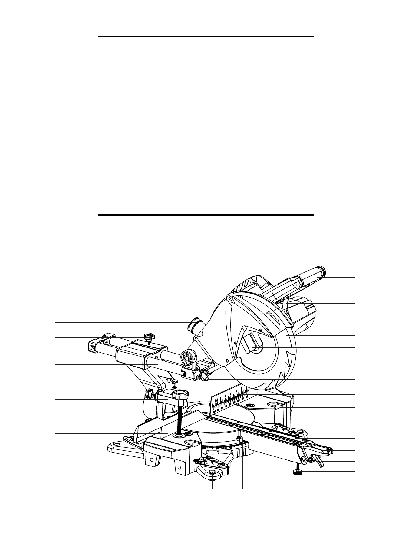
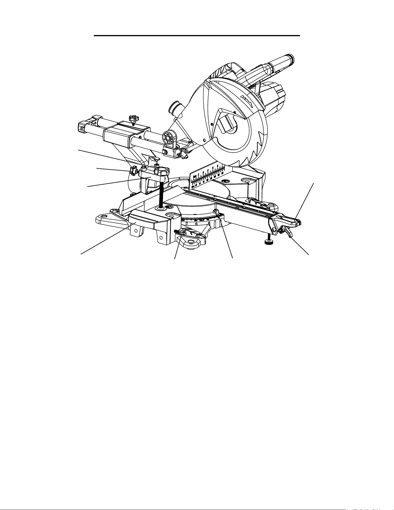
KNOW YOUR MITER SAW
UNPACKING & TRANSPORTING
• Clamp Assembly x 1
• Workpiece Support x 2
• Dust Collection Bag x 1
UNPACKING THE MITER SAW
Open the packaging and take out all loose parts from the box. Using the carrying handle and the slide rail, care-
fully lift the saw from the packaging and place it on a level work surface. Make sure all the components are ac-
counted for before discarding the packaging. If any part is missing or broken, please contact our customer service
at 1-800-232-1195.
Please go through the list and diagram to become familiarized with all the components on your miter saw. The
components will be referred to later in the manual for assembly and operation instructions.
1
8
4
11
2
9
6
5
12
21
22
23
3
10
7
13
20
14
15
19
18
16
17
INCLUDED ACCESSORIES:
10
• Allen Wrench x 1
• LR44 Battery x 3
• Instruction Manual x 1
TRANSPORTING THE MITER SAW
Before transporting your miter saw, make sure saw arm is locked down, the miter table is locked in position and the
slide lock knob is tightened. Only lift the saw by the carrying handle located on top of the motor or by the base. Do
not lift the saw using the guards or the operating handle.
Operating Handle
Blade Guard Lever
Motor
Blade Guard
Arbor Safety Guard
Saw Blade
Laser
Fence
Stationary Table
Miter Table
Table Insert
Miter Lock
Miter Stop Lever
Foot
Miter Scale
Mounting Hole
KNOW YOUR MITER SAW
Workpiece Support Table
Fixed Stop Rail
Movable Stop Rail
Clamp Assembly
Slide Bar
Sliding Lock Knob
Dust Port
On/Off Switch
Speed Adjustment Switch
Carrying Handle
Laser Switch
Workpiece Support Stop
Release Knob
Bevel Scale
Bevel Lock
1
2
3
4
5
6
7
8
9
10
11
12
13
14
15
16
17
18
19
20
21
22
23
24
25
26
27
28
29
30
31
24
26
27
25
28
29
30
31
11
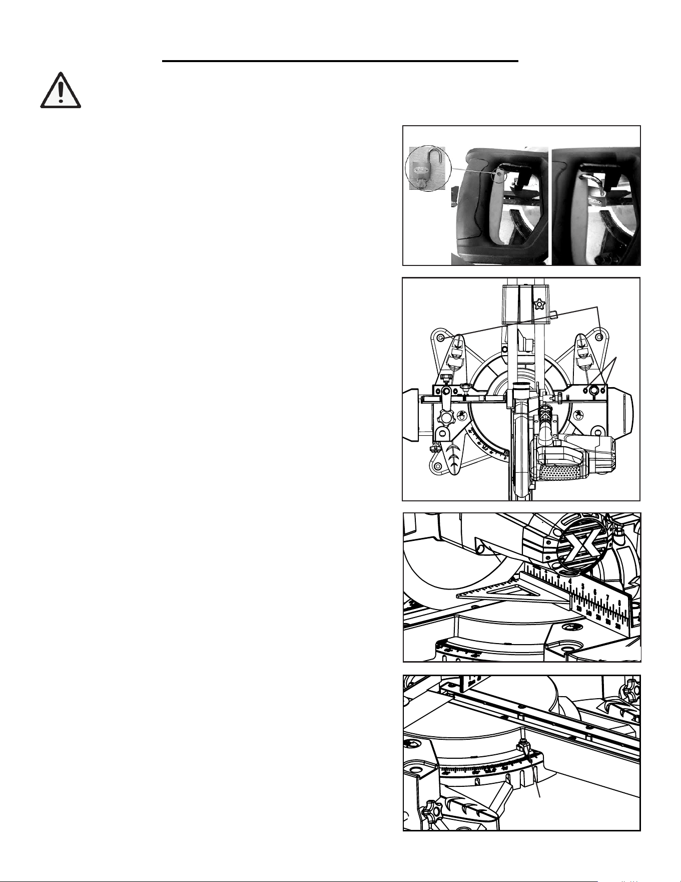
1. TO RAISE OR LOWER THE SAW ARM
The saw arm needs to be raised up before operation and
locked down for transporting and storing.
To raise saw arm from the lower position:
Holding the operating handle, lightly press down on the
saw arm and pull out the release knob. Slowly raise the
saw arm to the upper position.
Set the release knob into the deep groove to lock it in
the upper position. Set the release knob into the shallow
groove to prepare for operation.
To lower saw arm from the upper position:
Holding the operating handle, push the blade guard le-
ver and pull out the release knob.
Slowly lower the saw arm to the lower position and lock
the release knob into the deep groove.
2. TO BEVEL THE SAW ARM
The saw arm can bevel from 0° to 45° to the left. Hold
the operation handle and unlock the bevel lock by
turning it down clockwise.
Tilt the saw arm until the pointer indicates the desired
angle on the bevel scale.
Tighten the bevel lock. Make sure the saw arm is locked
in place and does not tilt.
3. TO ENGAGE/LOCK THE SLIDE BAR
The saw arm can be adjusted to extend out to different
lengths using the slide bar. Loosen the slide lock knob
and slide the saw arm to desired position.
Tighten the slide lock knob before transporting the mi-
ter saw and before non-sliding operations.
ASSEMBLY AND ADJUSTMENTS
Without plugging in your miter saw, read through and become familiarized with the following procedures of
handling and adjusting your miter saw.
Slide Lock Knob
Operating Handle
Blade Guard Lever
Bevel Lock
Bevel Scale
Release Knob
Deep groove
Shallow groove
12
ASSEMBLY AND ADJUSTMENTS
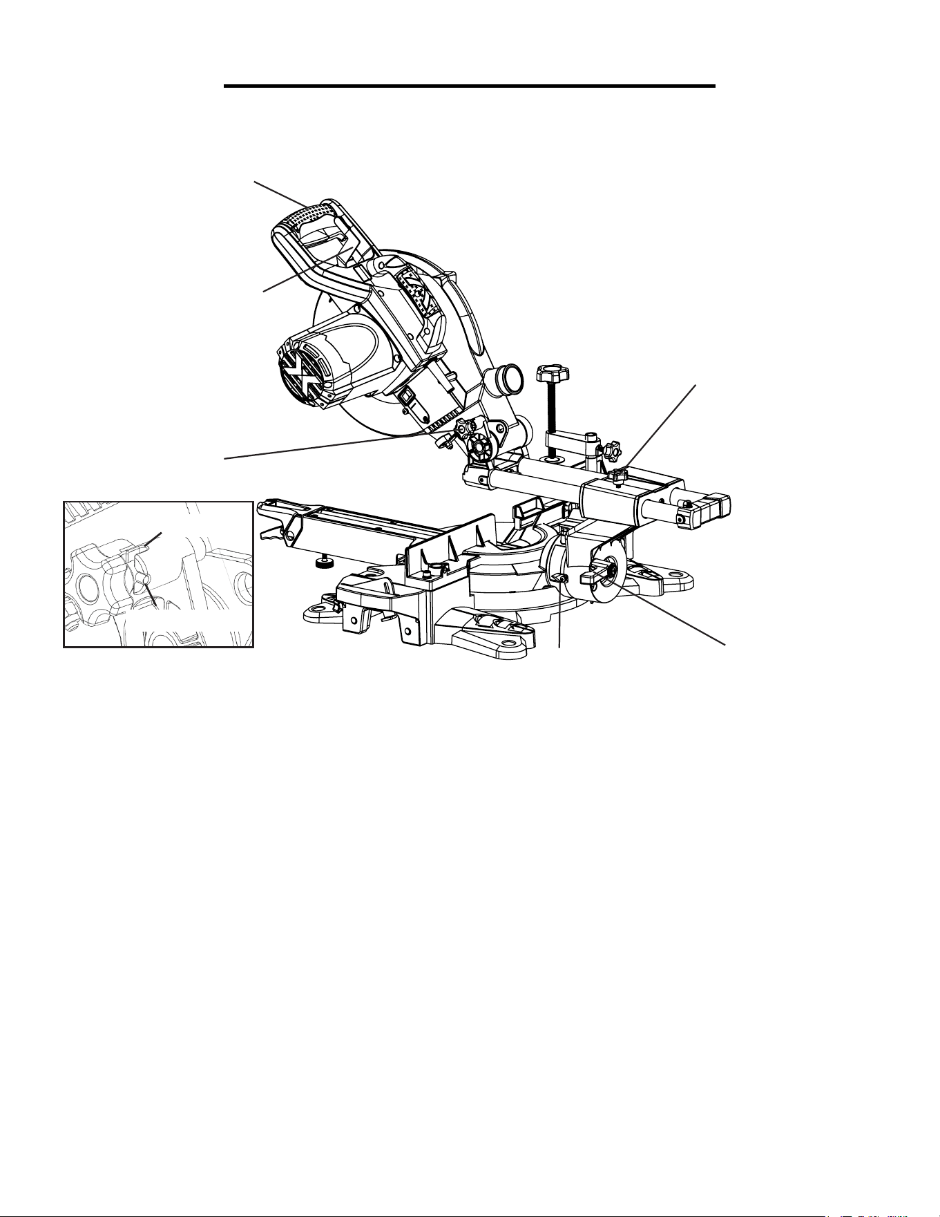
4. TO ADJUST THE MITER ANGLE
The rotary table can be adjusted from 0° to 45° to both left
and right to create miter cuts. To adjust the miter angle,
push down the miter lock and lift up the miter stop lever.
Rotate the miter table to the desired angle indicated by
the pointer on the miter scale. The rotary table features
positive click stops at 0°, 15°, 22.5°, 30°, and 45° in both
directions for quick settings.
Push up the miter lock to lock the miter table in place.
Release the miter stop lever to lock the table in place,
making sure it clicks into one of the stops.
Be sure the miter table is locked in place before making
a cut. Failure to do so can cause the table to move during
the cut, resulting in serious personal injury.
5. TO INSTALL THE SUPPORT TABLE
Attach the support tables by mounting them into the
holes on both sides of the miter saw. Adjust the table to
the suitable distance and tighten the table lock screws.
Pull up the work support stop to utilize the stop face to
set your cut to the desired length.
6. TO INSTALL THE CLAMP
The clamp assembly can be mounted on the left or right
side of the saw depending on the cutting task.
Attach the clamp assembly by inserting it into its
respective hole. Check that the clamp won’t interfere
with the blade travel and secure it in place with the
clamp lock screws.
Rotate the clamp knob to move it up or down as needed
for securing the workpiece. Check that the workpiece is
secure and will not wobble before cutting.
Miter Lock
Table Lock Screws
Support Table
Clamp Assembly
Clamp Lock Screws
Clamp Knob
Miter Stop Lever
Miter Scale
13
ASSEMBLY AND ADJUSTMENTS
SWITCH LOCK
The hole on the trigger (Fig. 1) is a safety feature that enables the
switch to be locked off. To lock off the switch, insert a padlock
through the hole and lock the padlock. This will prevent the switch
from being pressed down and reduce the risk of children acciden-
tally starting the machine.
BENCH MOUNTING
1. The miter saw base has holes in the four corners to facilitate
bench mounting (Fig. 2 - 1). Mount and fix the saw to a level, hori-
zontal bench or worktable using four bolts and nuts (not included).
2. If desired, you can mount the saw to a piece of 1/2˝ or thicker
plywood which can then be clamped to your work bench or moved
to other job sites and reclamped.
CAUTION: Make sure that the mounting surface is not warped.
Uneven surfaces can cause binding and inaccurate sawing.
A A
B B
C C
D D
E E
F F
G G
H H
12
12
11
11
10
10
9
9
8
8
7
7
6
6
5
5
4
4
3
3
2
2
1
1
DRAWN
CHK'D
APPV'D
MFG
Q.A
UNLESS OTHERWISE SPECIFIED:
DIMENSIONS ARE IN MILLIMETERS
SURFACE FINISH:
TOLERANCES:
LINEAR:
ANGULAR:
FINISH:
DEBURR AND
BREAK SHARP
EDGES
NAME
SIGNATURE
DATE
MATERIAL:
DO NOT SCALE DRAWING
REVISION
TITLE:
DWG NO.
SCALE:1:10
SHEET 1 OF 1
A2
WEIGHT:
70730 3D FIle1
SETTING THE FENCE SQUARE WITH THE BLADE
Note: The set square is not included.
1. Lower the saw arm down to the lower position and lock the
release knob.
2. Slide the saw arm to the back and tighten the slide lock knob.
3. Set the miter table to 0° and tighten the miter lock.
4. Loosen the four screws on the back of the fence (Fig. 2 - 2) with
an allen wrench.
5. Place a set square against the fence and alongside the saw blade
(Fig. 3). Adjust the fence position until it is 90° with the blade.
6. Tighten the four screws to secure the fence.
SETTING THE MITER SCALE POINTER
1. Loosen the screw holding the miter scale pointer (Fig. 4 - 1).
2. Adjust the direction of the pointer so that it accurately indicates
0° on the miter scale.
3. Tighten the screw on the pointer.
Fig. 2
14
Fig. 3
1
2
1
Fig. 4
WARNING: Remove the power plug before performing adjustments on the miter saw. Wear work
gloves when handling saw blades to protect your hands from possible injuries.
Fig. 1
ASSEMBLY AND ADJUSTMENTS
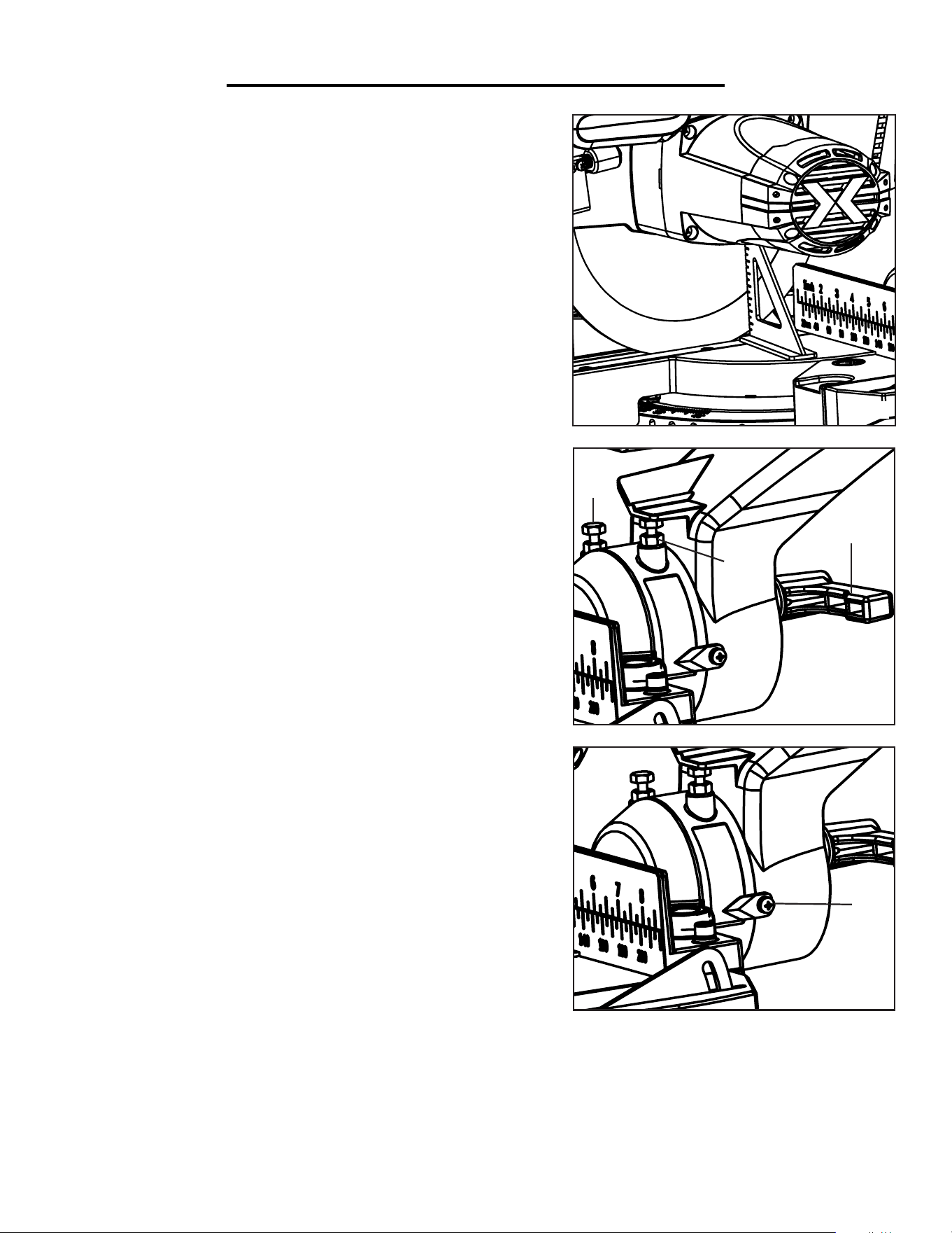
SETTING THE BLADE SQUARE WITH THE TABLE
1. Lower the saw arm to its lower position and lock the release knob.
2. Slide the saw arm to the back and tighten the sliding knob.
3. Set the miter table to 0° and tighten the miter lock.
4. Set the bevel angle to 0° (leaving the blade at 90° to the miter table)
and tighten the bevel lock.
5. Place a set square (not included) against the table and the flat part
of the saw blade (Fig. 5).
6. Wearing work gloves, rotate the blade by hand and check the
blade-to-table alignment at several points.
7. The edge of the set square and the saw blade should be parallel.
If the saw blade angles away from the set square, adjust as follows.
8. Use a spanner (not included) to loosen the lock nut securing the
0° bevel adjustment screw (Fig 6 - 1).
9. Holding the operating handle, loosen the bevel lock (Fig 6 - 2).
10. Adjust the 0° bevel adjustment screw to bring the saw blade into
alignment with the square.
11. Tighten the bevel adjustment screw and the lock nut. Tighten
the bevel lock.
NOTE: The above procedure can also be used to check the angle of
the saw blade to the table at the 45° bevel angle. The saw blade can
be adjusted at 45° with the 45° bevel adjustment screw (Fig. 6 - 3).
SETTING THE BEVEL SCALE POINTER
1. After setting the saw blade at 90° with the table, loosen the screw
holding the bevel scale pointer (Fig. 7 - 1).
2. Adjust the direction of the pointer so that it accurately indicates
0° on the bevel scale.
3. Tighten the screw on the pointer.
15
Fig. 5
Fig. 6
Fig. 7
1
1
3
2
DANGER! Never try to use a blade larger than the stated
capacity of the saw. Never use a blade that is too thick. It will
prevent the blade screw from properly securing the blade on the
spindle. Install the suitable blade for your cutting operation.
ASSEMBLY AND ADJUSTMENTS
A A
B B
C C
D D
E E
F F
G G
H H
J J
K K
L L
M M
N N
P P
R R
T T
24
24
23
23
22
22
21
21
20
20
19
19
18
18
17
17
16
16
15
15
14
14
13
13
12
12
11
11
10
10
9
9
8
8
7
7
6
6
5
5
4
4
3
3
2
2
1
1
DRAWN
CHK'D
APPV'D
MFG
Q.A
UNLESS OTHERWISE SPECIFIED:
DIMENSIONS ARE IN MILLIMETERS
SURFACE FINISH:
TOLERANCES:
LINEAR:
ANGULAR:
FINISH:
DEBURR AND
BREAK SHARP
EDGES
NAME
SIGNATURE
DATE
MATERIAL:
DO NOT SCALE DRAWING
REVISION
TITLE:
DWG NO.
SCALE:1:5
SHEET 1 OF 1
A0
WEIGHT:
70730 3D FIle1
CHANGING THE SAW BLADE
A A
B B
C C
D D
E E
F F
8
8
7
7
6
6
5
5
4
4
3
3
2
2
1
1
DRAWN
CHK'D
APPV'D
MFG
Q.A
UNLESS OTHERWISE SPECIFIED:
DIMENSIONS ARE IN MILLIMETERS
SURFACE FINISH:
TOLERANCES:
LINEAR:
ANGULAR:
FINISH:
DEBURR AND
BREAK SHARP
EDGES
NAME
SIGNATURE
DATE
MATERIAL:
DO NOT SCALE DRAWING
REVISION
TITLE:
DWG NO.
SCALE:1:10
SHEET 1 OF 1
A3
WEIGHT:
70730 3D FIle1
16
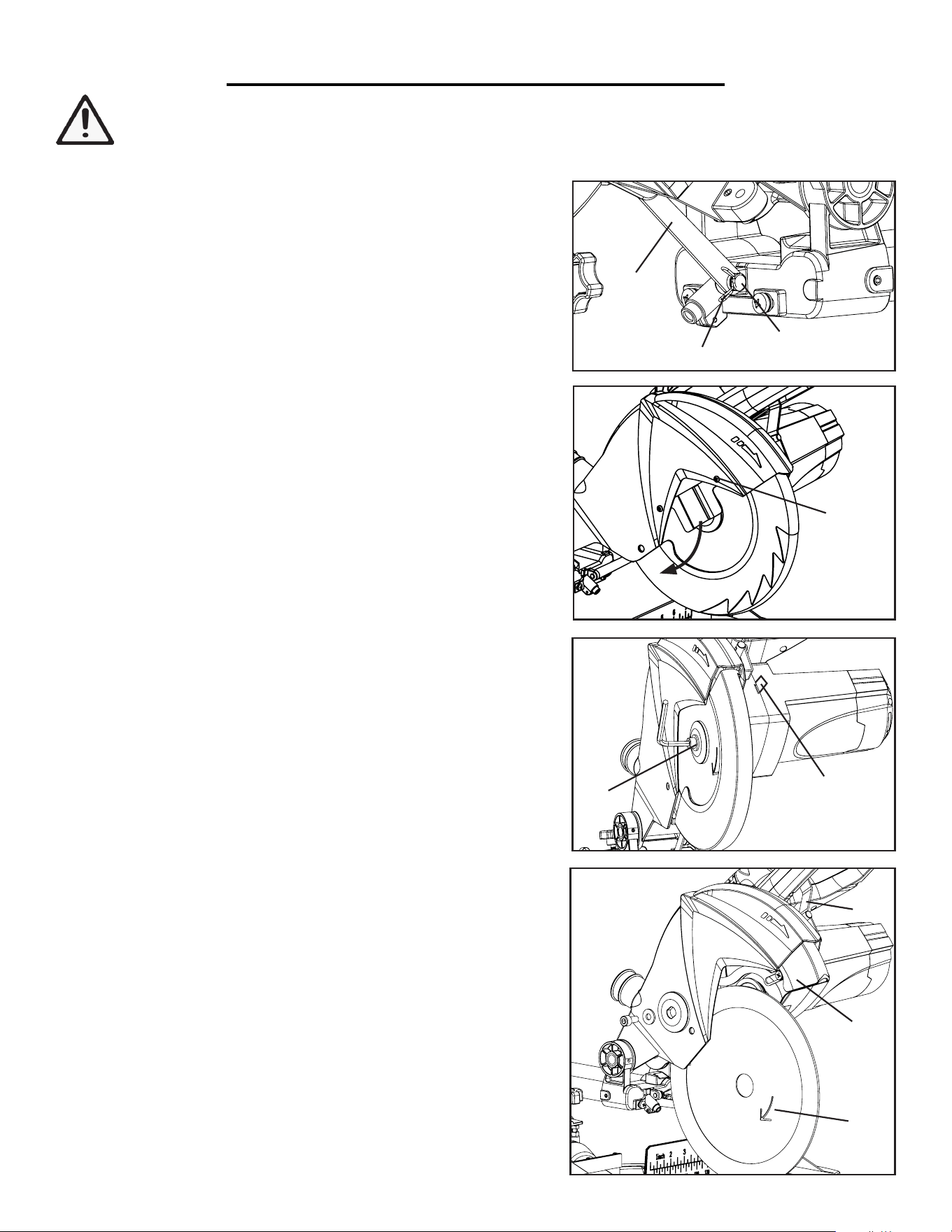
1. Place a piece of paper on the miter table to catch the screws.
2. Lift the saw arm to the upper position and lock it in place.
3. Remove the spring (Fig. 8 - 1) from the guide bar screw by
pushing together the two ends.
4. Using an allen wrench, unscrew the guide bar screw (Fig. 8 - 2)
and release the guide bar (Fig. 8 - 3) from the pin.
5. Loosen the screw on the right of the arbor safety guard (Fig.
9 - 1). Swing the safety guard downwards to expose the flange
screw. NOTE: the safety guard does not need to be taken off
from the saw.
6. Firmly press down the saw spindle lock (Fig. 10 - 1) to prevent
the saw blade from spinning. Using an allen wrench, turn the
arbor flange screw (Fig. 10 - 2) clockwise to loosen. Remove the
flange screw, washer and the outer flange (Fig 11).
7. Press down the blade guard lever (Fig. 11 - 1) to slide up the
saw blade guard (Fig. 11 - 2).
8. Slowly remove the blade by pulling it out in a downwards di-
rection (Fig 11). Clean the flange screw, outer flange and inner
flange.
9. Install the new saw blade by inserting the blade arbor into the
spindle. Return the blade guard into the original position.
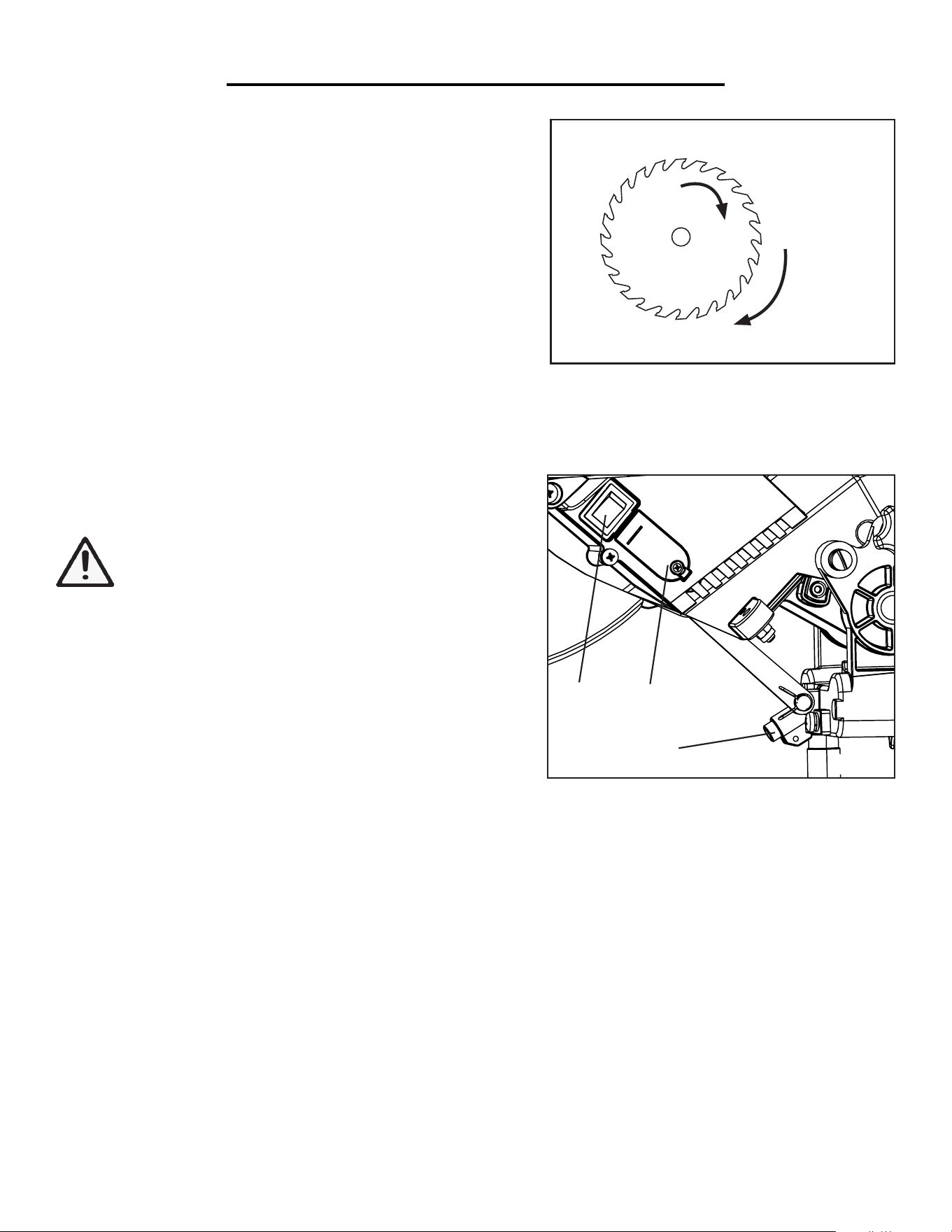
IMPORTANT: An arrow is printed on the left side of the blade
to indicate the direction of the blade teeth (Fig. 11 - 3). Install the
blade with the blade teeth and the arrow pointing downwards, so
that the arrow on the blade is in the same as the direction of the
blade’s rotation (Fig. 12).
Fig. 8
Fig. 9
1
3
1
1
3
2
2
2
1
Fig. 10
Fig. 11
WARNING: Remove the power plug before performing adjustments on the miter saw. Wear work
gloves when handling saw blades to protect your hands from possible injuries.
ASSEMBLY AND ADJUSTMENTS
Blade rotate direction
Cutting direction
Fig. 12
10. Reinstall the outer flange, washer and flange screw. Hold
down the spindle lock (Fig. 10 - 1) and tighten the flange screw
with the allen wrench.
11. Return the arbor safety guard back in place, and tighten it
back onto the screw on the right.
10. Return the guide bar back to position (Fig. 8). Insert the
guide bar screw and tighten. Then reattach the spring onto the
screw.
IMPORTANT: Rotate the saw blade and make sure that it
does not wobble. Lower the saw arm and check if the blade
spins freely in the table insert in both perpendicular and 45°
angles.
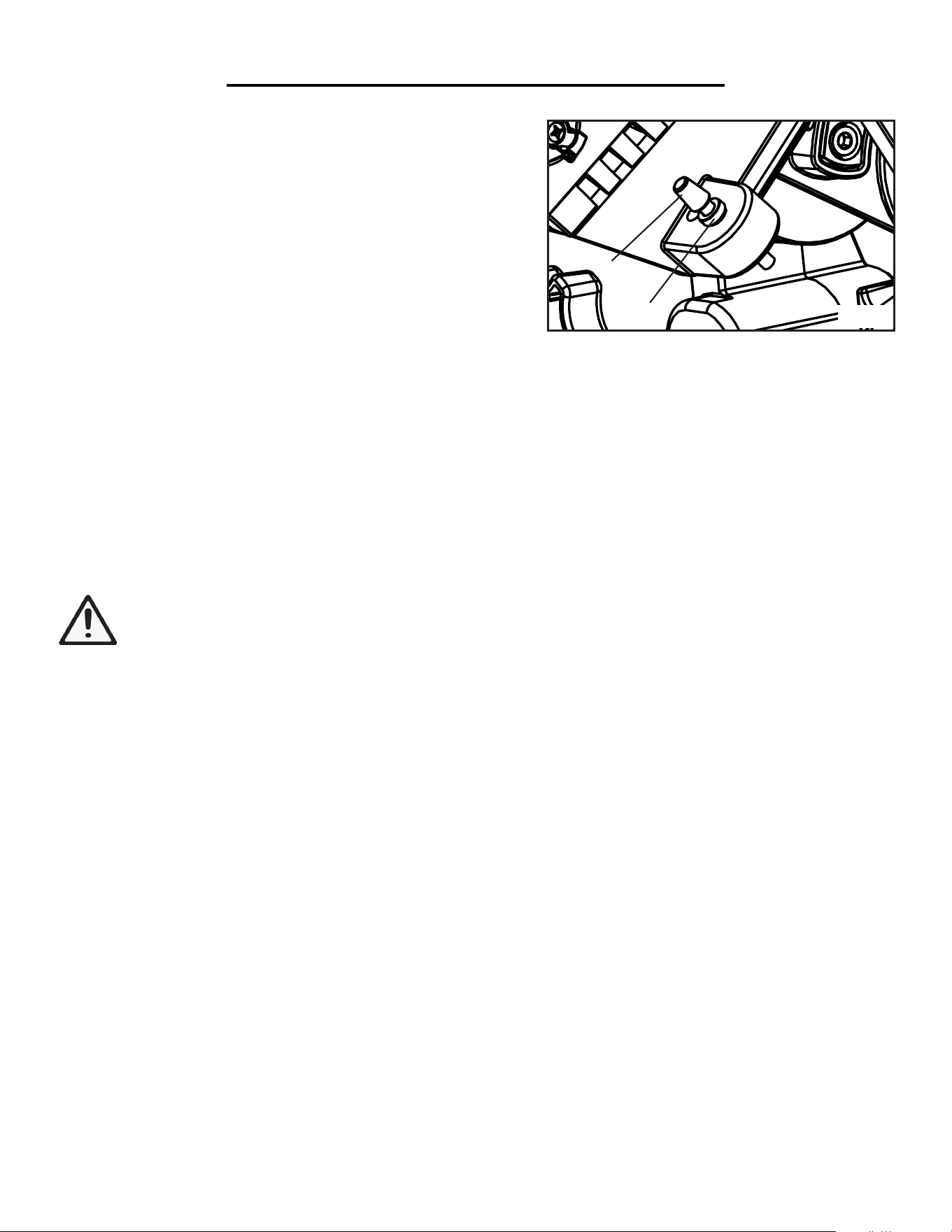
USING THE LASER
A laser line can be projected from the laser (Fig. 13 - 1) onto the
workpiece to provide a reference guide for the cut.
WARNING: Do not start directly into the laser. Do
not project the laser onto reflective surfaces.
To switch on the laser, move the ON/OFF switch (Fig. 13 - 2)
up to the “I” position. To switch off the laser, move the ON/
OFF switch down to the “O” position.
INSTALLING/REPLACING THE BATTERIES:
1. Switch off the laser to “O” position.
2. Unscrew and open the battery compartment cover (Fig. 13
- 3). Remove the used batteries and replace new batteries (3 x
LR44 Battery). Check that the battery terminals are positioned
correctly when inserting new batteries.
3. Close the battery compartment and tighten the screw.
1
Fig. 13
2
3
17
USING THE DUST COLLECTION BAG
WARNING: Do not use dust bag or dust collection when cutting metal. Risk of fire and explosion can
occur due to hot metal dust or flying sparks.
Use the dust collection bag for wood cutting operations. Squeeze together the metal ring on the dust bag and attach
it to the dust extraction port on the back of the saw.
Empty the dust bag by opening the zipper on the bottom of the bag. For efficient operation, empty the dust bag
when half full to allow for better air flow through the bag.
ASSEMBLY AND ADJUSTMENTS
CHANGING THE SAW BLADE SPEED
The miter saw can be operated with two speeds. The speed switch is located at the back of the saw arm. Select the
suitable speed for the material being cut. Do not change the blade speed while the miter saw is running.
1. LOW SPEED: 2000 RPM, recommended for cutting mild steel.
2. HIGH SPEED: 4500 RPM, recommended for cutting wood, plastic, aluminum, bronze alloy and copper alloy.
LIMITING THE CUTTING DEPTH
The saw cutting depth can be adjusted using the depth adjust-
ment screw located beside the laser switch.
1. Loosen the nut on the depth adjustment screw (Fig. 14 - 1).
2. Rotate the screw (Fig. 14 - 2) in or out to set the required cut-
ting depth. Tighten the nut to lock the depth adjustment screw
in place.
3. Check the cutting depth setting by completing a test cut.
1
2
Fig. 14
18
WARNING: Be sure to read and understand all the specific rules for your miter saw before attempting
to assemble or operate your miter saw.
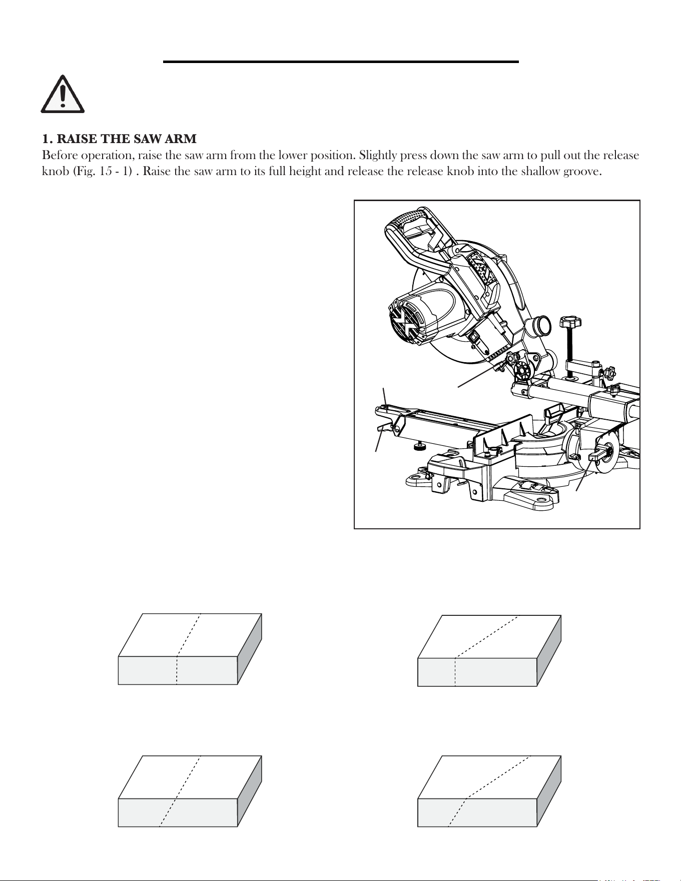
1. RAISE THE SAW ARM
Before operation, raise the saw arm from the lower position. Slightly press down the saw arm to pull out the release
knob (Fig. 15 - 1) . Raise the saw arm to its full height and release the release knob into the shallow groove.
OPERATION
CROSS CUT:
Miter table 0°, Saw arm 0°
MITER CUT:
Miter table 0 to 45° left or right, Saw arm 0°
BEVEL CUT:
Miter table 0°, Saw arm 0° to 45°,
COMPOUND CUT:
Miter table 0 to 45° left or right, Saw arm 0° to 45°
2. SET UP A CUT
The miter saw can be set up to create cuts at different
angles by adjusting the angle of the miter table and the
saw bevel angle.
To set up the miter table angle:
Push down the miter lock (Fig. 15 - 2) with your thumb
and lift the miter stop lever (Fig. 15 - 3) with your index
finger. Rotate the miter table until the pointer aligns with
angle of your choice on the miter scale. The miter table
features positive click stops at 0°, 15°, 22.5°, 30°, and 45°.
Release the miter stop lever to lock the table at a click
stop. Push up the miter lock to secure the miter table in
place. Check that the table is secured.
To set up the saw arm bevel angle:
Hold the operation handle with one hand and loosen the
bevel lock (Fig 15 - 4) in the back of the machine. Tilt the
saw arm to the desired bevel angle (between 0° and 45° to
the left). Tighten the bevel lock and make sure the saw
arm angle is secured.
Fig. 15
2
3
4
1
Refer to the diagram below for setting up your desired cut.
19
OPERATION
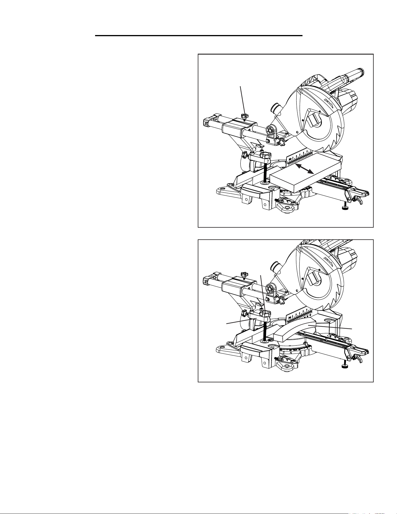
4. PLACE WORKPIECE
Place the workpiece flat on the table with one edge se-
curely against the fence. Turn on the laser to see where
the cut will land on the material (See Page 17 “Using
the Laser”).
Warped Boards: If the board is warped, place the
convex side against the fence (Fig. 17 - 1). CAUTION:
The board could break and jam the lade if the concave
side is placed against the fence
Long Boards: When cutting long workpieces, support
the opposite end of the material with the support table, a
roller stand or a work surface that is level with the saw table.
5. SECURE WORKPIECE
Secure the workpiece with the clamping device on the
fixed table whenever possible to prevent the material
from moving during the cutting operations. Position
the clamp (Fig. 17 - 2) in the position that does not
interfere with the travel of the saw. Tighten it in place
with the two clamp lock screws. Lower the clamp knob
(Fig. 17 - 3) to clamp the workpiece and tighten.
3. SLIDING FUNCTION
For materials width<4 inches (100 mm)
When cutting materials with a width less that 4 inches,
the sliding mechanism isn’t necessary. Loosen the slide
lock knob (Fig. 16 - 1) and use the operating handle to
push back the saw arm. Tighten the slide lock knob.
For materials width >4 inches (100 mm)
When cutting materials with a width longer that 4 inch-
es, the saw arm will need to slide to cut through the
workpiece. Loosen the slide lock knob so the saw arm
can slide through the entire workpiece.
NOTE: When cutting metal, it is very important to clamp down the workpiece as any movement of the metal
workpiece will cause damage to the blade.
6. SELECT THE SUITABLE SPEED
Select the suitable speed for the material being cut. Do not change the blade speed while the miter saw is running.
1. LOW SPEED: 2000 RPM, recommended for cutting mild steel.
2. HIGH SPEED: 4500 RPM, recommended for cutting wood, plastic, aluminum, bronze alloy and copper alloy.
2
1
3
1
Width
Fig. 16
Fig. 17
20

OPERATION
7. CHECK BEFORE OPERATION
• Check that the miter table does not rotate and the saw arm does not bevel.
• Check that the workpiece is fully supported, against the fence and securely clamped down.
• Check that you have selected the right blade speed for you material to be cut.
• Without turning on the saw, perform a dry run of the cutting operation to check that nothing is obstructing the
path of the saw.
WARNING: Before operating the miter saw, make sure to equip yourself with dust mask, ear protec-
tion, safety glasses and work gloves for protection from possible injuries. Tie back long hair and do not
wear loose clothing or jewelry.
8. PERFORMING THE CUT
1. Hold the operating handle firmly and press the blade guard lever with your index finger. Squeeze the switch trig-
ger to turn on the saw.
2. Allow the blade to reach full speed.
• Without sliding: Slowly lower the blade into and through the workpiece.
• With sliding: Pull the saw arm all the way to the front. Slowly lower the blade into the workpiece while steadily
pushing it away from you until the workpiece is cut. CAUTION: Never slide the saw arm towards you when cutting.
Always push away.
3. Release the switch trigger and allow the saw blade to stop rotating before slowly raising the blade out of the work-
piece. Wait until the blade fully stops before removing the workpiece. After cutting all the workpieces, unplug your
miter saw before leaving.
SPECIFIC RULES FOR CUTTING METAL
NOTE: This miter saw is designed for woodworking and can only handle occasional metal cutting. Excessive metal
cutting can dull the saw blade quickly and cause damage to the miter saw.
• Recommended:
- Aluminum, bronze alloy, copper alloy, and mild steel without heat treatment.
• Not recommended:
- Steel with heat treatment or surface hardening treatment, as it will damage saw blade very fast.
- Pure copper, as the material is sticky. Use HSS saw blade with fine teeth and cut copper at high speed.
• Forbidden:
- Magnesium and magnesium alloys. WARNING: Do not cut magnesium or magnesium alloys. Serious
accident and even death could occur.
1. Only use saw blades specific for metal cutting or for handling multipurpose operations.
2. Initial contact of the saw blade with the metal workpiece must be slow and gentle. Apply constant force to feed the
blade into the workpiece. Avoid movement or vibration of the workpiece during cutting may damage the saw blade.
3. Do not use dust bag or dust collection when cutting metals. Risk of fire and explosion can occur due to hot metal
dust or flying sparks!
WARNING: Be sure to tighten the miter lock and bevel lock before making a cut. Failure to do so
could result in the table moving during the cut and may cause serious personal injuries.
21

MAINTENANCE
WARNING: Always ensure that the tool is switched off and the plug is removed from the outlet before
making any adjustments or maintenance procedures.
Any damage to this tool should be repaired and carefully inspected by qualified repair personnel before use. Have
your power tool serviced by a qualified repair person using only identical replacement parts to maintain the safety
of the power tool.
GENERAL MAINTENANCE
1. Keep the tool’s air vents unclogged and clean at all times.
2. Remove dust and dirt using a soft brush or a clean cloth after each use. Remember to wear eye protection.
WARNING: Do not at any time let brake fluids, gasoline, petroleum-based products, penetrating oils come in
contact with the plastic parts. Avoid using solvents when cleaning plastic parts. Chemicals can damage, weaken or
destroy plastic which may result in serious personal injury.
3. Regularly check that all screws are tight. They may vibrate loose over time.
4. Regularly check the power cord for any damage. Power cord maintenance must be carried out by authorized
personnels in order to avoid safety hazards.
CARBON BRUSHES
If you see excessive sparks during cutting, it is time to inspect and replace the carbon brushes. Have an experienced
person perform the inspection and maintenance. The carbon brushes are located inside the motor housing, which
can be accessed by unscrewing and opening the motor housing cover. Replace both carbon brushes when either
has less than 1/4 in. length of carbon remaining, or if the spring or wire is damaged or burned. Reinstall the motor
housing.
STORAGE
1. Store the miter saw and its accessories in a dark, dry and frost-proof place that is inaccessible to children.
2. The optimum storage temperature is between 41 to 86˚F (5 to 30˚C).
3. Cover the miter saw in order to protect it from dust and moisture. Preferably store it in its original packaging with
the instruction manual.
4. Remove the batteries before storing the miter saw for a long period of time. Store the battery at a cool and dry
place away from fire and heat.
PRODUCT DISPOSAL
When the product reaches the end of its lifetime, please do not dispose of it with household waste. Electrical and
electronic products are hazardous to the environment and human health due to the presence of hazardous sub-
stances. Take the product to your local recycling facility for it to be responsibly recycled to minimize impacts on the
environment.
22
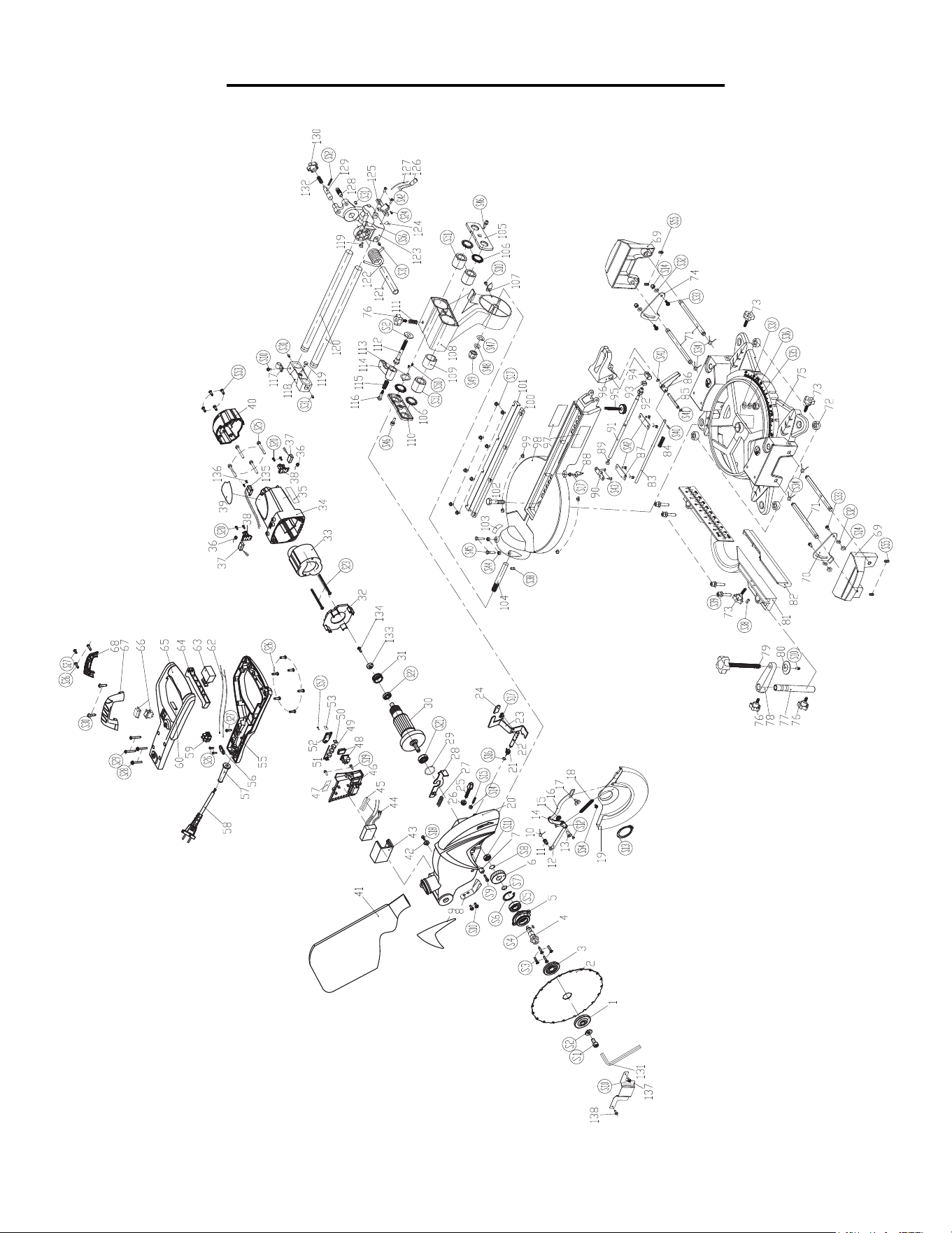
EXPLODED VIEW & PARTS LIST
23

EXPLODED VIEW & PARTS LIST
No. Part No. Part Description Qty.
1 70730-001 Outer Pressure Block 1
2 70730-002 216 Blade 1
3 70730-003 Inner Pressure Block 1
4 70730-004 Spindle 1
5 70730-005 Front Cover 1
6 70730-006 Big Gear 1
7 70730-007 Shield Ring 1
8 70730-008 Splash Guard 1
9 70730-009 Nameplate Label 1
10 70730-010 Clamps 1
11 70730-011 Rod Journal 1
12 70730-012 Connecting Rod 1
13 70730-013 Positioning Bolt (Blade Guard) 1
14 70730-014 Positioning Rod 1
15 70730-015 Rod Sleeve 1
16 70730-016 Movable Connecting Rod 1
17 70730-017 Shield Connection Bolt 1
18 70730-018 Return Tension Spring 1
19 70730-019 Shield 1
20 70730-020 Head Cover 1
21 70730-021 Guard Lock Knob Spring 1
22 70730-022 Locking Shaft 1
23 70730-023 Lock Lever 1
24 70730-024 Gum Cover 1
25 70730-025 Cutting Depth Adjustment Knob 1
26 70730-026 Cutting Depth Adjustment Nut 1
27 70730-027 Locking Spring 1
28 70730-028 Locking Bar 1
29 70730-029 Ø26XØ2 O-Ring 1
30 70730-030 Armature 1
31 70730-031 Bearing Bush 1
32 70730-032 Fan Shroud 1
33 70730-033 Stator 1
34 70730-034 Housing 1
35 70730-035 Ptrotective Tip Labeling 1
36 70730-036 Carbon Brush Coil Spring 2
37 70730-037 Carbon Brush 2
38 70730-038 Brush Holder 2
39 70730-039 Parameters Stickers 1
40 70730-040 Cover 1
41 70730-041 Crumb Bag 1
42 70730-042 Return Stop 1
43 70730-043 Soft Start Box 1
44 70730-044 Controller 1
45 70730-045 Ø8XØ60 Heat Shrink Tubing 2
46 70730-046 Infrared Battery Pack 1
47 70730-047 Infrared Label 1
48 70730-048 Infrared Switch 1
49 70730-049 Button Battery 3
50 70730-050 Positive Insert 1
51 70730-051 Negative Insert 1
52 70730-052 Infrared Battery Cover 1
53 70730-053 Insulating Strip 1
No. Part No. Part Description Qty.
55 70730-055 Handle Seat 1
56 70730-056 Pressure Block 1
57 70730-057 Cable Shield 1
58 70730-058 Cable 1
59 70730-059 Connection Terminal 1
60 70730-060 Variable Speed Switch Indicator 1
62 70730-062 Lead Wire (320mm) 2
63 70730-063 Switch 1
64 70730-064 Switch Knob 1
65 70730-065 Handle Cover 1
66 70730-066 Variable Switch 1
67 70730-067 Lifting Seat 1
68 70730-068 Lifting Cover 1
69 70730-069 Workbench Extension 2
70 70730-070 Positioning Block Slice 1
71 70730-071 Guide Rod 4
72 70730-072 Rubber Feet 4
73 70730-073 Guide Rod Lock Knob 3
74 70730-074 Positioning Block 1
75 70730-075 Base Plate 1
76 70730-076 Lever Lock Knob 3
77 70730-077 Clamping Block Shaft 1
78 70730-078 Aluminum Base 1
79 70730-079 Clamping Block Knob 1
80 70730-080 Clamp 1
81 70730-081 Main on Board 1
82 70730-082 Side on Board 1
83 70730-083 Angle Position Rod 1
84 70730-084 Angle Positioining Lever 1
85 70730-085 Turnplate Handle Shaft 1
86 70730-086 Fast Lock Trigger 1
87 70730-087 Angle Positioning Seat 2
88 70730-088 Turntable Pointer 1
89 70730-089 Clamping Pad 1
90 70730-090 Turnable Lock Rod Clamp 1
91 70730-091 Turnplate Lock Bar 1
92 70730-092 Lock Lever Adjusting Nut 1
93 70730-093 Locating Sleeve Lock 1
94 70730-094 Active Connector 1
95 70730-095 Levelling Lock Button 1
96 70730-096 Turntable Handle 1
97 70730-097 Label 1
98 70730-098 Turntable 1
99 70730-099 Antifriction Mat 4
100 70730-100 Left Kerf Board 1
101 70730-101 Right Kerf Board 1
102 70730-102 Turnplate Bolt 1
103 70730-103 Calibration Label 1
104 70730-104 Inclined Shaft 1
105 70730-105 Front Shroud 1
106 70730-106 Wool Washer (Ø30XØ20X3) 3
107 70730-107 Diagonal Pointer 1
108 70730-108 Oblique Transposition 1
24

EXPLODED VIEW & PARTS LIST
No. Part No. Part Description Qty.
109 70730-109 Nylon Sleeve 1
110 70730-110 Back Shroud 1
111 70730-111 Rail Locking Knob Spring 1
112 70730-112 Bevel Lock Bolt 1
113 70730-113 Wool Gasket Clamp 1
114 70730-114 Bevel Locking Handle 1
115 70730-115 Turnable Bevel Locking Spring 1
116 70730-116 Turnable Oblique Screw Bolt 1
117 70730-117 Cable Card 1
118 70730-118 Back Seat Guide Bar 1
119 70730-119 Collision Column 2
120 70730-120 Pull Rod 2
121 70730-121 Spring Pin 1
122 70730-122 Large Torsion 1
123 70730-123 Spring Seat 1
124 70730-124 Infrared Indicator 1
125 70730-125 infrared Lamp Holder 1
126 70730-126 Infrared Lamp 1
127 70730-127 Ø4X100 Ash Pipe 1
128 70730-128 Positioning Bolt (Slide Rail) 1
129 70730-129 Bit lock Pin 1
130 70730-130 Bit Lock Button 1
131 70730-131 6mm Allen Wrench 1
132 70730-132 Spring 1
133 70730-133 Magnet Ring 1
134 70730-134 Screw M4X6 1
135 70730-135 Sensor 1
136 70730-136 Screw ST2.9X8 2
137 70730-137 Arbor Safety Guard 1
138 70730-138 Shoulder Screw M4x4 2
S1 70730-201 M8X20 Hexagon Socket Head Cap Screws 1
S2 70730-202 Ø8 Washer 2
S3 70730-203 M4X14 Countersunk Screws 4
S4 70730-204 5X5X10 Flat Key 1
S5 70730-205 6202RS Deep Groove Ball Bearings 1
S6 70730-206 Ø35 Hole Circlip 1
S7 70730-207 Ø15 Shaft Circlip 1
S8 70730-208 Ø14 Shaft Circlip 1
S9 70730-209 M4X14 Hexagon Socket Head Cap Screws 1
S10 70730-210 ØM4X8 Cross Recessed Pan Head Screw
Kit
6
S11 70730-211 607 Deep Groove Ball Bearings 1
S12 70730-212 4X6 Flat Head Rivet 2
S13 70730-213 φ38 Shaft Circlip 1
S14 70730-214 M5 Hexagon Nuts 5
S15 70730-215 5X18 Allen Flat End Set Screws 1
S16 70730-216 Ø8 Opening Ring 1
S17 70730-217 M4X122 Cross Recessed Pan Head Screw
Kit
11
S18 70730-218 M4X8 Hexagon Socket Head Cap Screws 1
S19 70730-219 M4X14 Cross Recessed Pan Head Screw
Kit
2
S20 70730-220 ST3.5X10 Cross Recessed pan Head
Tapping Screws
4
No. Part No. Part Description Qty.
S21 70730-221 6201RS Deep Groove Ball Bearings 1
S22 70730-222 6000RS Deep Groove Ball Bearings 1
S23 70730-223 ST5X65 Cross Recessed Pan Head Tapping
Screws
2
S24 70730-224 ST2.9x9 Cross Recessed Pan head Tapping
Screws
1
S25 70730-225 M5X30 Cross Recessed pan head Screw Kit 4
S26 70730-226 M4X30 Cross Recessed Pan Head Tapping
Screws
10
S27 70730-227 ST4X12 Cross Recessed Pan Head Tapping
Screws
2
S28 70730-228 M4X30 Cross Recessed Pan Head Screw
Kit
2
S29 70730-229 ST4X25 Cross Recessed pan head Tapping
Screws
2
S30 70730-230 ST5X12 Cross-Recessed Pan head Screw
Kit
2
S31 70730-231 M6X6 Hexagon Socket Set Screws
(Slide Rail)
4
S32 70730-232 Ø5 Wave Washer 4
S33 70730-233 M5X16 Cross-Recessed Pan Head Screw
Kit
4
S34 70730-234 Ø10 Shaft Circlip 4
S35 70730-235 M10 Hexagon Nuts 1
S36 70730-236 Ø10 Wave Washer 1
S37 70730-237 Ø10 Washer 1
S38 70730-238 M6X12 Hexagon Socekt Set Screws 2
S39 70730-239 M6X30 Hexagon head Screw Key
Combination
4
S40 70730-240 Ø2X14 Cylindrical Pin 1
S41 70730-241 Ø6 Opening Ring 2
S42 70730-242 M5X12 Cross Recessed Pan Head Screw
Kit
6
S43 70730-243 M5X12 Cross-Recessed Countersunk Head
Screws
4
S44 70730-244 M6 Hex Nuts 2
S45 70730-245 M6X25 Hexagon Head Bolt 2
S46 70730-246 M5X14 Hexagon Head Screw Key
Combination
2
S47 70730-247 Ø12 Washer 1
S48 70730-248 Ø12 Wave Washer 1
S49 70730-249 M12 Hexagon Nuts 1
S50 70730-250 ST3X5 Cross-Recessed Pan Head
Tapping Screws
2
S51 70730-251 Linear Bearings (LM25UU) 3
S52 70730-252 3X18 Elastic Cylindrical Pin 1
S53 70730-253 ST4.2X16 4
S54 70730-254 M4X6 Cross Recessed Pan Head Screw Kit 1
S55 70730-255 M6X6 Hexagon Socket Set Screws
(Support Table)
4
S56 70730-256 M5X8 Hexagon Socket Set Screw 1
S57 70730-257 ST2.9x10 Cross-Recessed pan Head
Tapping Screws
1
25

WARRANTY STATEMENT
WEN Products is committed to building tools that are dependable for years. Our warranties are consistent with
this commitment and our dedication to quality.
LIMITED WARRANTY OF WEN CONSUMER POWER TOOLS PRODUCTS FOR HOME USE
GREAT LAKES TECHNOLOGIES, LLC (“Seller”) warrants to the original purchaser only, that all WEN con-
sumer power tools will be free from defects in material or workmanship for a period of two (2) years from date of
purchase. Ninety days for all WEN products, if the tool is used for professional use.
SELLER’S SOLE OBLIGATION AND YOUR EXCLUSIVE REMEDY under this Limited Warranty and, to
the extent permitted by law, any warranty or condition implied by law, shall be the repair or replacement of parts,
without charge, which are defective in material or workmanship and which have not been misused, carelessly
handled, or misrepaired by persons other than Seller or Authorized Service Center. To make a claim under this
Limited Warranty, you must make sure to keep a copy of your proof of purchase that clearly defines the Date of
Purchase (month and year) and the Place of Purchase. Place of purchase must be a direct vendor of Great Lakes
Technologies, LLC. Third party vendors such as garage sales, pawn shops, resale shops, or any other secondhand
merchant void the warranty included with this product. Contact [email protected] or 1-800-232-
1195 to make arrangements for repairs and transportation.
When returning a product for warranty service, the shipping charges must be prepaid by the purchaser. The prod-
uct must be shipped in its original container (or an equivalent), properly packed to withstand the hazards of ship-
ment. The product must be fully insured with a copy of the warranty card and/or the proof of purchase enclosed.
There must also be a description of the problem in order to help our repairs department diagnose and fix the
issue. Repairs will be made and the product will be returned and shipped back to the purchaser at no charge.
THIS LIMITED WARRANTY DOES NOT APPLY TO ACCESSORY ITEMS THAT WEAR OUT
FROM REGULAR USAGE OVER TIME INCLUDING BELTS, BRUSHES, BLADES, ETC. ANY IM-
PLIED WARRANTIES SHALL BE LIMITED IN DURATION TO TWO (2) YEARS FROM DATE OF
PURCHASE. SOME STATES IN THE U.S., SOME CANADIAN PROVINCES DO NOT ALLOW LIMI-
TATIONS ON HOW LONG AN IMPLIED WARRANTY LASTS, SO THE ABOVE LIMITATION MAY
NOT APPLY TO YOU.
IN NO EVENT SHALL SELLER BE LIABLE FOR ANY INCIDENTAL OR CONSEQUENTIAL DAM-
AGES (INCLUDING BUT NOT LIMITED TO LIABILITY FOR LOSS OF PROFITS) ARISING FROM
THE SALE OR USE OF THIS PRODUCT. SOME STATES IN THE U.S. AND SOME CANADIAN
PROVINCES DO NOT ALLOW THE EXCLUSION OR LIMITATION OF INCIDENTAL OR CON-
SEQUENTIAL DAMAGES, SO THE ABOVE LIMITATION OR EXCLUSION MAY NOT APPLY TO
YOU.
THIS LIMITED WARRANTY GIVES YOU SPECIFIC LEGAL RIGHTS, AND YOU MAY ALSO HAVE
OTHER RIGHTS WHICH VARY FROM STATE TO STATE IN THE U.S., PROVINCE TO PROVINCE
IN CANADA AND FROM COUNTRY TO COUNTRY.
THIS LIMITED WARRANTY APPLIES ONLY TO PORTABLE ELECTRIC TOOLS, BENCH POW-
ER TOOLS, OUTDOOR POWER EQUIPMENT AND PNEUMATIC TOOLS SOLD WITHIN THE
UNITED STATES OF AMERICA, CANADA AND THE COMMONWEALTH OF PUERTO RICO. FOR
WARRANTY COVERAGE WITHIN OTHER COUNTRIES, CONTACT THE WEN CUSTOMER SUP-
PORT LINE.
26

THANKS FOR REMEMBERING