12-INCH SLIDE
COMPOUND MITER SAW
Instruction Manual
MODEL MM1213
IMPORTANT: Your new tool has been engineered and manufactured to WEN’s highest standards for dependability,
ease of operation, and operator safety. When properly cared for, this product will supply you years of rugged,
trouble-free performance. Pay close attention to the rules for safe operation, warnings, and cautions. If you use
your tool properly and for its intended purpose, you will enjoy years of safe, reliable service.
NEED HELP? CONTACT US!
Have product questions? Need technical support? Please feel free to contact us:
TECHSUPPOR[email protected]1-847-429-9263 (M-F 8AM-5PM CST)
For replacement parts and the most up-to-date instruction manuals, visit WENPRODUCTS.COM

CONTENTS
WELCOME 3
Introduction ..................................................................................................... 3
Specifications ................................................................................................... 3
SAFETY 4
General Safety Rules ........................................................................................ 4
Miter Saw Safety Warnings .............................................................................. 6
Electrical Information ....................................................................................... 8
BEFORE OPERATING 9
Unpacking & Transportation .............................................................................9
Know Your Miter Saw .................................................................................... 10
Assembly & Adjustments ............................................................................... 11
OPERATION & MAINTENANCE 19
Operation ....................................................................................................... 19
Maintenance ....................................................................................................22
Troubleshooting Guide ................................................................................... 23
Exploded View & Parts List .............................................................................25
Warranty Statement ........................................................................................29
To purchase accessories and replacement parts for your tool, visit WENPRODUCTS.COM
2
Replacement Miter Saw Blades (Model BL1248)
Replacement Carbon Brushes (Part MM1213-223)
Miter Saw Stand (Model MSA200, MSA750T, MSA330)

SPECIFICATIONS
INTRODUCTION
Thanks for purchasing the WEN Miter Saw. We know you are excited to put your tool to work, but first, please
take a moment to read through the manual. Safe operation of this tool requires that you read and understand this
operator’s manual and all the labels affixed to the tool. This manual provides information regarding potential safety
concerns, as well as helpful assembly and operating instructions for your tool.
NOTE: The following safety information is not meant to cover all possible conditions and situations that may occur.
WEN reserves the right to change this product and specifications at any time without prior notice.
At WEN, we are continuously improving our products. If you find that your tool does not exactly match this manual,
please visit wenproducts.com for the most up-to-date manual or contact our customer service at 1-847-429-9263.
Keep this manual available to all users during the entire life of the tool and review it frequently to maximize
safety for both yourself and others.
Indicates danger, warning, or caution. The safety symbols and the explanations with them deserve your
careful attention and understanding. Always follow the safety precautions to reduce the risk of fire, electric shock
or personal injury. However, please note that these instructions and warnings are not substitutes for proper ac-
cident prevention measures.
Model Number MM1213
Motor 120V, 60 Hz, 15A
Laser Type 650 nm < 1mW, EN60825-1:2014
Laser Class Class II
No-Load Speed 3800 RPM
Blade Part Number BL1248
Blade Size 12 Inches (305mm)
Arbor Size 1 Inch (25.4mm)
Kerf 2.4mm
Teeth 48T Carbide Teeth
Dust Port Outer Diameter 1.55 in. (39.50mm)
Dust Port Inner Diameter 1.28 in. (32.5mm)
Miter Table Angles 0° to 45° Left & Right
Bevel Cut Angles 0° to 45° Left & Right
Positive Miter Stops 0°, 15°, 22.5°, 30°, 45°
Cutting Capacity
0° Miter, 90° Bevel 13.0 in. x 4.1 in.
45° Miter Left, 90° Bevel 13.0 in. x 2.4 in.
45° Miter Right, 90° Bevel 13.0 in. x 1.3 in.
0° Miter, 45° Bevel 9.1 in. x 4.1 in.
45° Miter Left, 45° Bevel 9.1 in. x 2.4 in.
45° Miter Right, 45° Bevel
9.1 in. x 1.3 in.
Product Weight 45.0 Pounds
Product Dimensions 34.3 in. x 23.6 in. x 27.0 in.
3

GENERAL SAFETY RULES
WORK AREA SAFETY
1. Keep work area clean and well lit. Cluttered or dark
areas invite accidents.
2. Do not operate power tools in explosive atmo-
spheres, such as in the presence of flammable liquids,
gases or dust. Power tools create sparks which may ig-
nite the dust or fumes.
3. Keep children and bystanders away while operating
a power tool. Distractions can cause you to lose control.
ELECTRICAL SAFETY
1. Power tool plugs must match the outlet. Never mod-
ify the plug in any way. Do not use any adapter plugs
with earthed (grounded) power tools. Unmodified plugs
and matching outlets will reduce risk of electric shock.
2. Avoid body contact with earthed or grounded surfac-
es such as pipes, radiators, ranges and refrigerators.
There is an increased risk of electric shock if your body
is earthed or grounded.
3. Do not expose power tools to rain or wet conditions.
Water entering a power tool will increase the risk of elec-
tric shock.
4. Do not abuse the cord. Never use the cord for car-
rying, pulling or unplugging the power tool. Keep cord
away from heat, oil, sharp edges or moving parts.
Damaged or entangled cords increase the risk of electric
shock.
5. When operating a power tool outdoors, use an ex-
tension cord suitable for outdoor use. Use of a cord
suitable for outdoor use reduces the risk of electric
shock.
6. If operating a power tool in a damp location is un-
avoidable, use a ground fault circuit interrupter (GFCI)
protected supply. Use of a GFCI reduces the risk of elec-
tric shock.
PERSONAL SAFETY
1. Stay alert, watch what you are doing and use com-
mon sense when operating a power tool. Do not use a
power tool while you are tired or under the influence
of drugs, alcohol or medication. A moment of inatten-
tion while operating power tools may result in serious
personal injury.
2. Use personal protective equipment. Always wear
eye protection. Protective equipment such as a respira-
tory mask, non-skid safety shoes and hearing protection
used for appropriate conditions will reduce the risk of
personal injury.
3. Prevent unintentional starting. Ensure the switch is
in the off-position before connecting to power source
and/or battery pack, picking up or carrying the tool.
Carrying power tools with your finger on the switch or
energizing power tools that have the switch on invites
accidents.
4. Remove any adjusting key or wrench before turning
the power tool on. A wrench or a key left attached to a
rotating part of the power tool may result in personal
injury.
5. Do not overreach. Keep proper footing and balance
at all times. This enables better control of the power
tool in unexpected situations.
6. Dress properly. Do not wear loose clothing or jew-
elry. Keep your hair and clothing away from moving
parts. Loose clothes, jewelry or long hair can be caught
in moving parts.
Safety is a combination of common sense, staying alert and knowing how your item works. The term “power tool”
in the warnings refers to your mains-operated (corded) power tool or battery-operated (cordless) power tool.
SAVE THESE SAFETY INSTRUCTIONS.
WARNING! Read all safety warnings and all instructions. Failure to follow the warnings and instructions may
result in electric shock, fire and/or serious injury.
4

GENERAL SAFETY RULES
7. If devices are provided for the connection of dust
extraction and collection facilities, ensure these are
connected and properly used. Use of dust collection
can reduce dust-related hazards.
POWER TOOL USE AND CARE
1. Do not force the power tool. Use the correct power
tool for your application. The correct power tool will
do the job better and safer at the rate for which it was
designed.
2. Do not use the power tool if the switch does not turn
it on and off. Any power tool that cannot be controlled
with the switch is dangerous and must be repaired.
3. Disconnect the plug from the power source and/or
the battery pack from the power tool before making
any adjustments, changing accessories, or storing
power tools. Such preventive safety measures reduce
the risk of starting the power tool accidentally.
4. Store idle power tools out of the reach of children
and do not allow persons unfamiliar with the power
tool or these instructions to operate the power tool.
Power tools are dangerous in the hands of untrained us-
ers.
5. Maintain power tools. Check for misalignment or
binding of moving parts, breakage of parts and any
other condition that may affect the power tool’s opera-
tion. If damaged, have the power tool repaired before
use. Many accidents are caused by poorly maintained
power tools.
6. Keep cutting tools sharp and clean. Properly main-
tained cutting tools with sharp cutting edges are less
likely to bind and are easier to control.
7. Use the power tool, accessories and tool bits, etc.
in accordance with these instructions, taking into ac-
count the working conditions and the work to be per-
formed. Use of the power tool for operations different
from those intended could result in a hazardous situa-
tion.
8. Use clamps to secure your workpiece to a stable
surface. Holding a workpiece by hand or using your
body to support it may lead to loss of control.
9. KEEP GUARDS IN PLACE and in working order.
SERVICE
1. Have your power tool serviced by a qualified repair
person using only identical replacement parts. This
will ensure that the safety of the power tool is main-
tained.
CALIFORNIA PROPOSITION 65 WARNING
Some dust created by power sanding, sawing, grinding,
drilling, and other construction activities may contain
chemicals, including lead, known to the State of Califor-
nia to cause cancer, birth defects, or other reproductive
harm. Wash hands after handling. Some examples of
these chemicals are:
• Lead from lead-based paints.
• Crystalline silica from bricks, cement, and other
masonry products.
• Arsenic and chromium from chemically treated
lumber.
Your risk from these exposures varies depending on
how often you do this type of work. To reduce your ex-
posure to these chemicals, work in a well-ventilated area
with approved safety equipment such as dust masks
specially designed to filter out microscopic particles.
Safety is a combination of common sense, staying alert and knowing how your item works. The term “power tool”
in the warnings refers to your mains-operated (corded) power tool or battery-operated (cordless) power tool.
SAVE THESE SAFETY INSTRUCTIONS.
WARNING! Read all safety warnings and all instructions. Failure to follow the warnings and instructions may
result in electric shock, fire and/or serious injury.
5

MITER SAW SAFETY WARNINGS
SAW BLADE SAFETY
1. Always wear protective gloves when handling saw
blades.
2. Only use blades with correct size and type for both
your miter saw and your workpiece.
• The rated diameter of the saw blade is 12" with a 1 inch
(25.4mm) arbor.
• The no-load speed of the miter saw is 6000 RPM. The
maximum permissible speed of your saw blade should
always be higher than the no-load rotational speed of
the saw.
3. Never use damaged or deformed saw blades. Only use
sharp blades.
4. Install the saw blade in the correct orientation indi-
cated in the instructions.
5. Keep hands out of path of saw blade. Never use your
hands to remove sawdust, chips or workpiece near the
saw blade or the cutting path of the saw.
6. Never reach around saw blade or reach in back of the
saw blade.
7. Do not use blades made from high-speed steel, abra-
sive blades, metal-cutting blades or masonry-cutting
blades. The guards of this saw are not designed to pro-
tect against the failure of such blades.
8. The use of accessories or attachments not recom-
mended by the manufacturer may result in a risk of per-
sonal injury.
PERSONAL SAFETY
1. Operate in a well ventilated area. Keep the floor area
around the miter saw level and free of slippery substanc-
es or other tripping hazards.
2. Wear ANSI-approved safety goggles to protect your
eyes from sparks and saw dust. Use hearing protection
to protect yourself from hearing loss.
3. People with pacemakers should consult their
physician(s) before use. Electromagnetic fields in close
proximity to pacemakers could cause pacemaker inter-
ference or pacemaker failure.
4. Wear work gloves when handling saw blades. DO NOT
wear gloves while operating the saw.
5. Sawdust is harmful to your health. Use NIOSH-ap-
proved dust masks or other respiratory protection dur-
ing operation and cleaning.
6. Always turn off and unplug the miter saw before mak-
ing any adjustments or repair tasks. Never adjust the
miter saw or the workpiece while the saw the running.
7. The lock down pin is to be used only to lock the head
in place for carrying and storage. It is not to be used for
any cutting operation.
8. Never use damaged or incorrect blade flanges or bolt.
The blade flanges and bolt were specially designed for
your saw, for optimum performance and safety of opera-
tion.
9. Do not use to cut metal, logs, tree limbs, or uneven
lumber.
10. Wet lumber, green (unseasoned) lumber, and pres-
sure treated lumber all have an increased potential for
kickback and should only be cut with a blade specifically
designed for that lumber type. Wear a NIOSH-approved
respirator and have appropriate ventilation whenever
cutting pressure treated lumber.
PREPARING THE MITER SAW
1. When transporting the miter saw, carry it by either the
carrying handle or the base. Never carry the device by its
guards or its accessories. Make sure that the lower part
of the saw blade is covered by the blade guard during
transportation.
2. Securely bolt the miter saw onto a miter saw stand or
a workbench before operating.
3. Examine the miter saw for any damaged or missing
parts. Replace or repair damaged parts before operation.
Periodically check that all nuts, bolts and other fasteners
are properly tightened.
WARNING! Do not operate the miter saw until you have read and understood the following instructions and
the warning labels.
6

6. During slide cutting, always push the saw blade away
from you. Do not pull the saw towards you.
7. Never cut more than one piece at a time. Do not stack
workpieces together.
8. Turn off tool and wait for saw blade to stop before
moving workpiece or changing settings. Do not slow or
stop a blade with a piece of wood. Let the blade come
to rest naturally. Do not attempt to free a jammed blade
while the machine is still running.
9. To reduce risk of injury, return carriage to the full rear
position after each crosscut operation.
LASER SAFETY
ATTENTION: LASER RADIATION. Class 2 laser.
DO NOT STARE INTO THE BEAM
1. Do not look directly into the laser beam with unpro-
tected eyes. Never look into the path of the beam.
2. Never point the laser beam towards reflecting sur-
faces. Never point the laser towards people or animals.
Even a laser beam with a low output can cause damage
to the eyes.
3. Never open the laser module as unexpected exposure
to the beam can occur. The laser cannot be replaced with
a different type of laser.
4. Repairs of the laser may only be carried out by the
laser manufacturer or an authorized representative.
MITER SAW SAFETY WARNINGS
SECURE YOUR WORKPIECE
1. Always position the workpiece on the miter table and
firmly against the fence. Use the included hold-down
clamp to secure the workpiece. Never perform any op-
eration freehand.
2. Use a clamp or other securing methods to support the
workpiece whenever possible.
3. When cutting round workpieces, use clamps on both
sides of the table to prevent the workpiece from turning.
Position the convex (curved) side against the fence.
4. Always support long workpieces properly using
stands or roller tables.
5. Never hand-hold a workpiece that is too small to be
clamped, as it can be launched away and cause injury.
Use proper support and guides to secure the small
workpiece.
DURING CUTTING OPERATIONS
1. Make sure the path of the saw blade is clear of ob-
struction. Before turning on the miter saw, do a dry run
and make sure that the saw blade does not touch any-
thing other than the workpiece during its entire line of
travel.
2. Always stand to one side when operating the saw.
Never have any part of the body in line with the path of
the saw.
3. Feed work into a blade against the direction of rotation
of the blade only.
4. Do not use the miter saw unless all guards are in
place. Do not operate with any guard disabled, damaged,
or removed. Moving guards must move freely and close
instantly.
5. Turn on the miter saw and let it reach full speed, then
slowly lower the saw into the workpiece. This will help
produce safer and cleaner cuts.
WARNING! Do not operate the miter saw until you have read and understood the following instructions and
the warning labels.
7

ELECTRICAL INFORMATION
1. EXAMINE EXTENSION CORD BEFORE USE. Make sure your extension cord is properly wired and in good condi-
tion. Always replace a damaged extension cord or have it repaired by a qualified person before using it.
2. DO NOT ABUSE EXTENSION CORD. Do not pull on cord to disconnect from receptacle; always disconnect by pull-
ing on plug. Disconnect the extension cord from the receptacle before disconnecting the product from the extension
cord. Protect your extension cords from sharp objects, excessive heat and damp/wet areas.
3. USE A SEPARATE ELECTRICAL CIRCUIT FOR YOUR TOOL. This circuit must not be less than a 12-gauge wire
and should be protected with a 15A time-delayed fuse. Before connecting the motor to the power line, make sure
the switch is in the OFF position and the electric current is rated the same as the current stamped on the motor
nameplate. Running at a lower voltage will damage the motor.
GUIDELINES AND RECOMMENDATIONS FOR EXTENSION CORDS
When using an extension cord, be sure to use one heavy enough to carry the current your product will draw. An
undersized cord will cause a drop in line voltage resulting in loss of power and overheating. The table below shows
the correct size to be used according to cord length and ampere rating. When in doubt, use a heavier cord. The
smaller the gauge number, the heavier the cord.
AMPERAGE
REQUIRED GAUGE FOR EXTENSION CORDS
25 ft. 50 ft. 100 ft. 150 ft.
15A 14 gauge 12 gauge Not Recommended
IMPORTANT: Servicing a double-insulated product requires extreme care and knowledge of the system, and
should be done only by qualified service personnel using identical replacement parts. Always use original factory
replacement parts when servicing.
1. POLARIZED PLUGS. To reduce the risk of electric shock, this equipment has a polarized plug (one blade is wider
than the other). This plug will fit in a polarized outlet only one way. If the plug does not fit fully in the outlet, reverse
the plug. If it still does not fit, contact a qualified electrician to install a proper outlet. Do not modify the machine
plug or the extension cord in any way.
2. GROUND FAULT CIRCUIT INTERRUPTER PROTECTION (GFCI) should be provided on the circuit or outlet used
for this power tool to reduce the risk of electric shock.
3. SERVICE AND REPAIR. To avoid danger, electrical appliances must only be repaired by qualified service techni-
cian using original replacement parts.
DOUBLE-INSULATED TOOLS
The tool’s electrical system is double insulated where two systems of insulation are provided. This
eliminates the need for the usual three-wire grounded power cord. Double insulated tools do not need
to be grounded, nor should a means for grounding be added to the product. All exposed metal parts
are isolated from the internal metal motor components with protecting insulation.
8

UNPACKING
With the help of a friend or trustworthy foe, carefully remove the miter saw from the packaging. Make sure to take
out all contents and accessories. Do not discard the packaging until everything is removed. Check the packing list
below to make sure you have all of the parts and accessories. If any part is missing or broken, please contact our
customer service at 1-847-429-9263.
PACKING LIST
UNPACKING & TRANSPORTATION
DESCRIPTION QTY.
Miter Saw 1
6mm Hex Wrench 1
Dust Bag 1
Clamp 1
Left Extension Table 1
Right Extension Table 1
Saw Blade 1
Miter Lock Knob 1
The tools listed below are not included but are required for either assembly or adjustment.
• Mounting Hardware
• Combination Square
• Phillips-head Screwdriver
TRANSPORTING THE MITER SAW
Before transporting your miter saw, make sure saw arm is locked down, the miter table is locked in position and
the slide lock knob is tightened. Only lift the saw by the carrying handle located on top of the belt housing or at the
back of the rails. Do not lift the saw using the guards or the operating handle.
WARNING! Do not plug in or turn on the tool until it is fully assembled according to the instructions. Failure
to follow the safety instructions may result in serious personal injury.
9
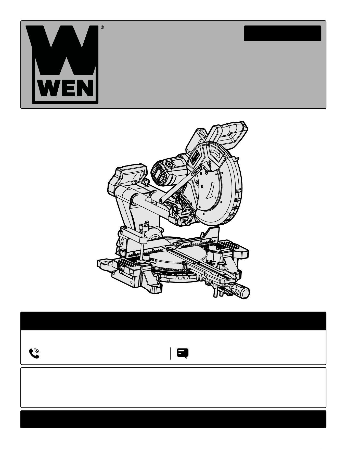
KNOW YOUR MITER SAW
Dust Port
Sliding Arm Lock
Safety Lock
Handle
Carbon Brush Cover
Motor
Handle
Blade Cover
Workpiece Clamp
Adjustable Fence
Fixed Fence
Miter Angle Indicator
Kerf Board
Miter Lock Knob
Extension Table
Miter Stop Lever
Handle
Extension Table Lock
Fence Locking Knob
Clamp Locking Knob
Workpiece Stop
Bevel Locking Knob
Power Trigger
Laser Switch
Bevel Angle Scale
10
1
ASSEMBLY & ADJUSTMENTS
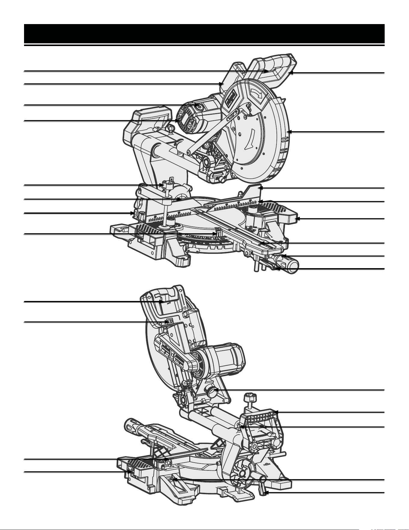
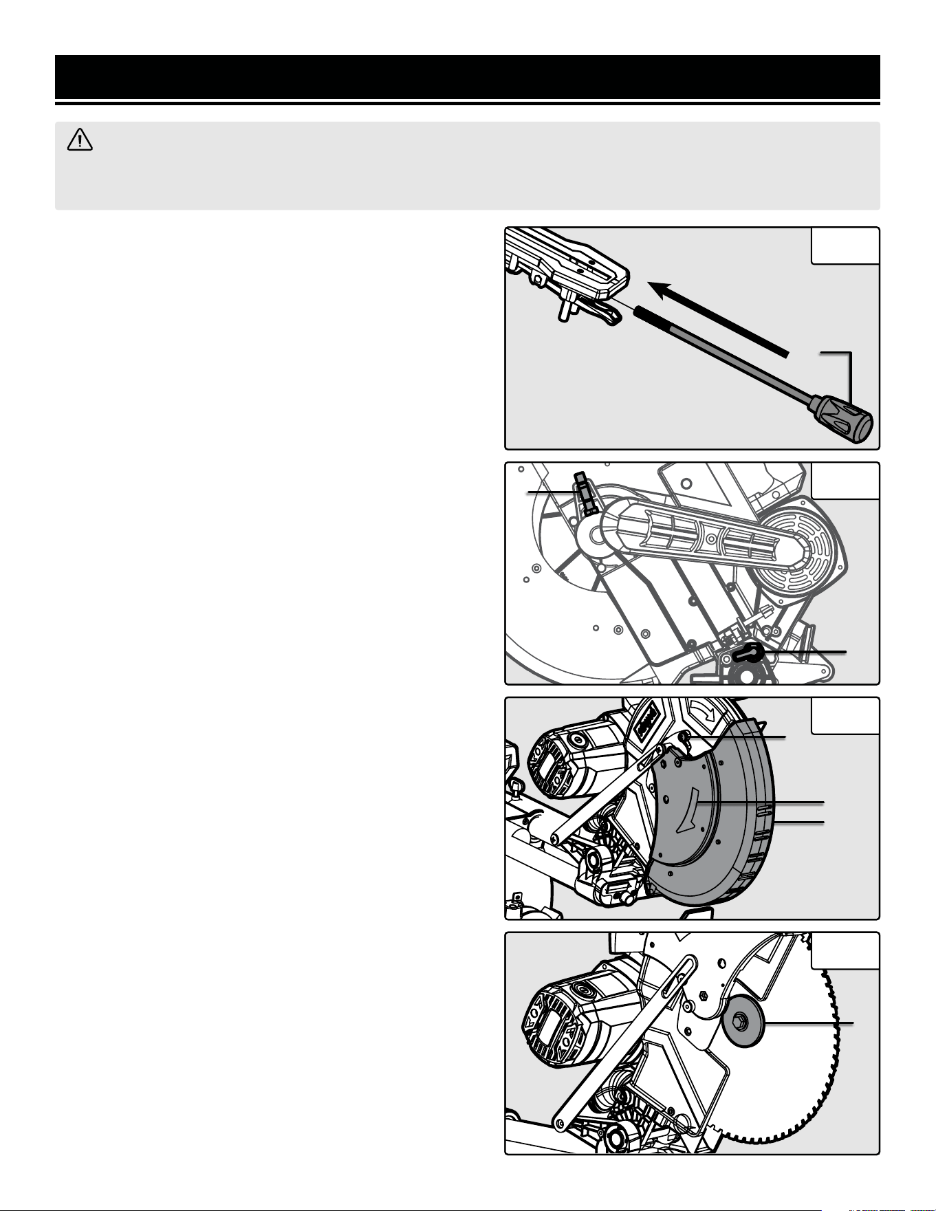
INSTALLING THE MITER LOCK KNOB
1. Screw the miter lock knob (Fig. A - 1) into the miter lock
until hand-tight. Do not overtighten; this could damage the
miter lock.
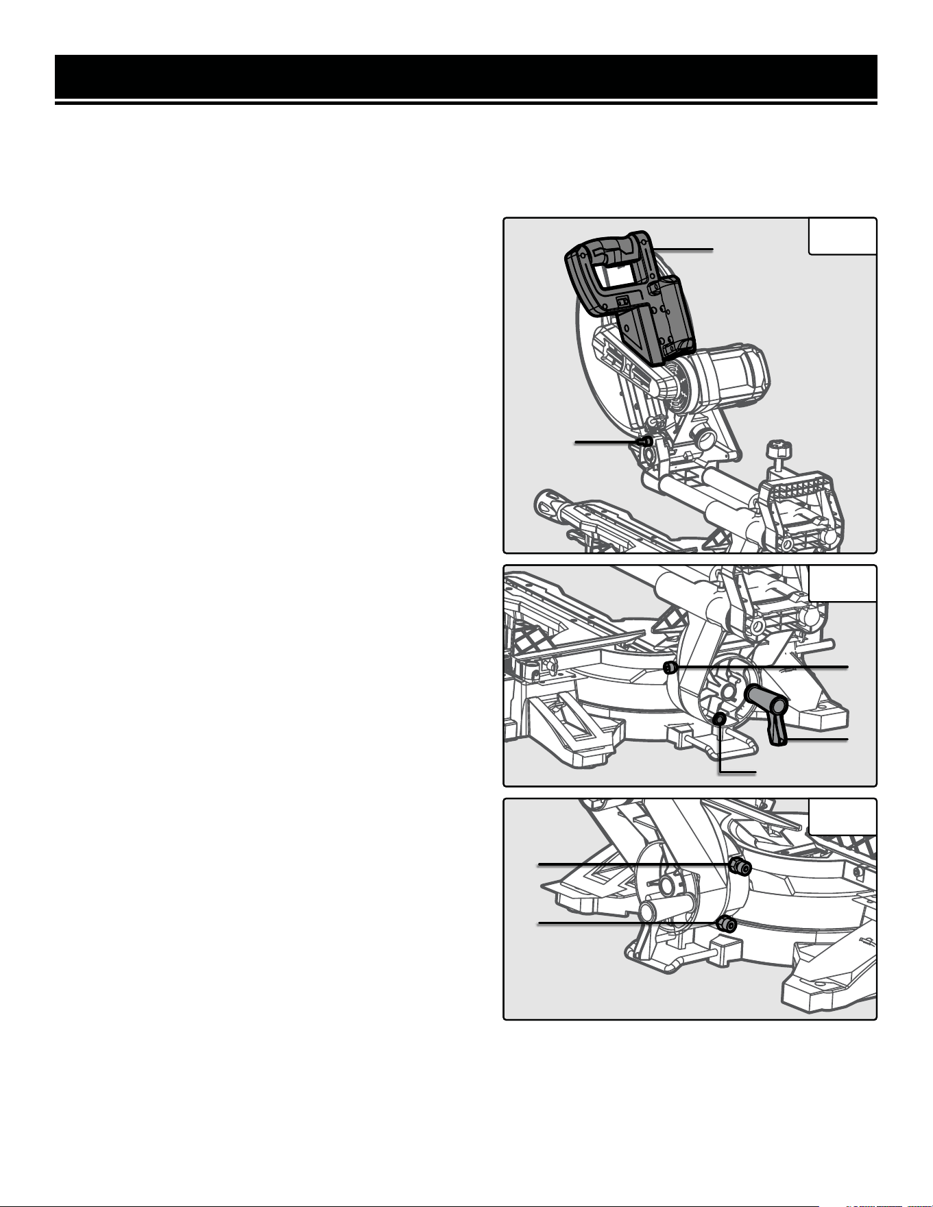
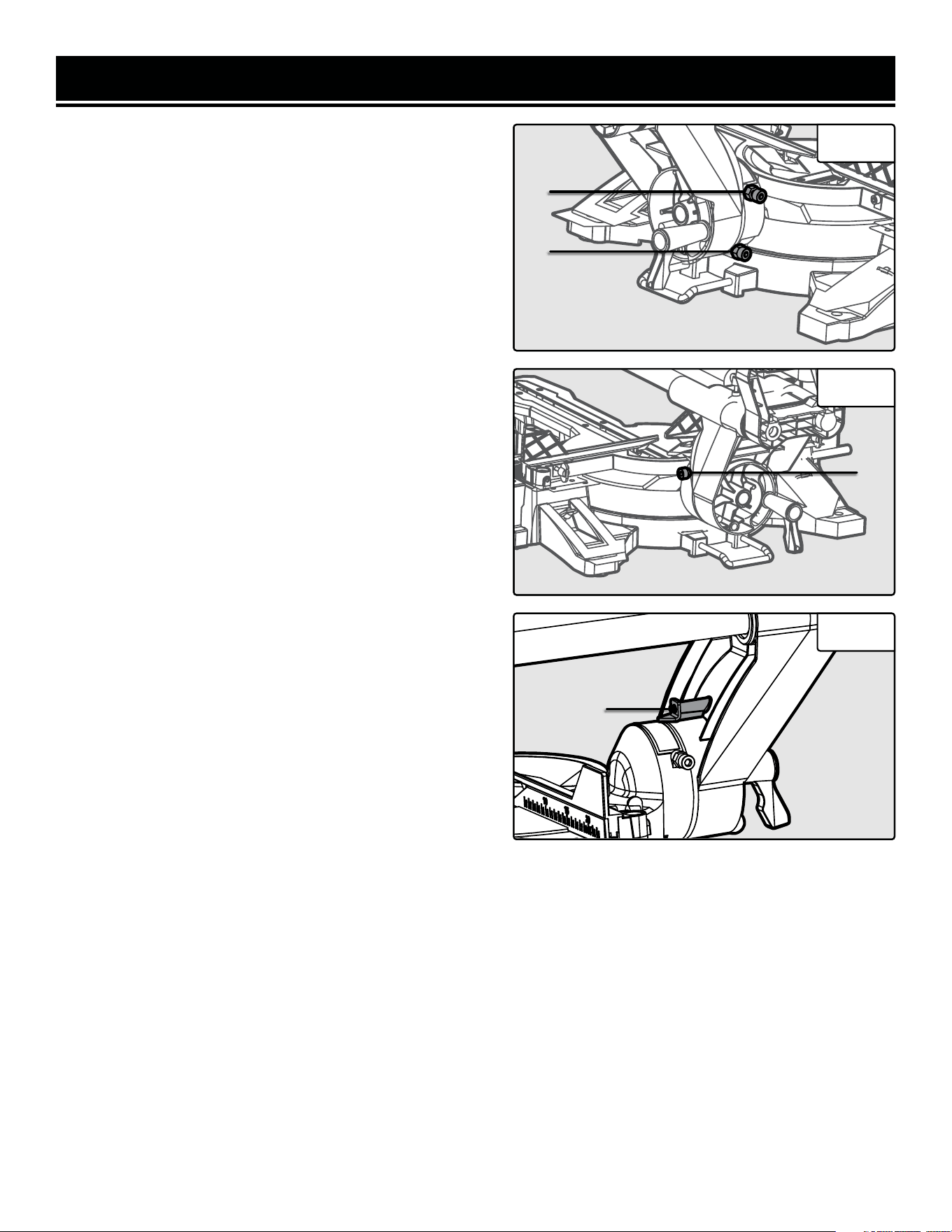
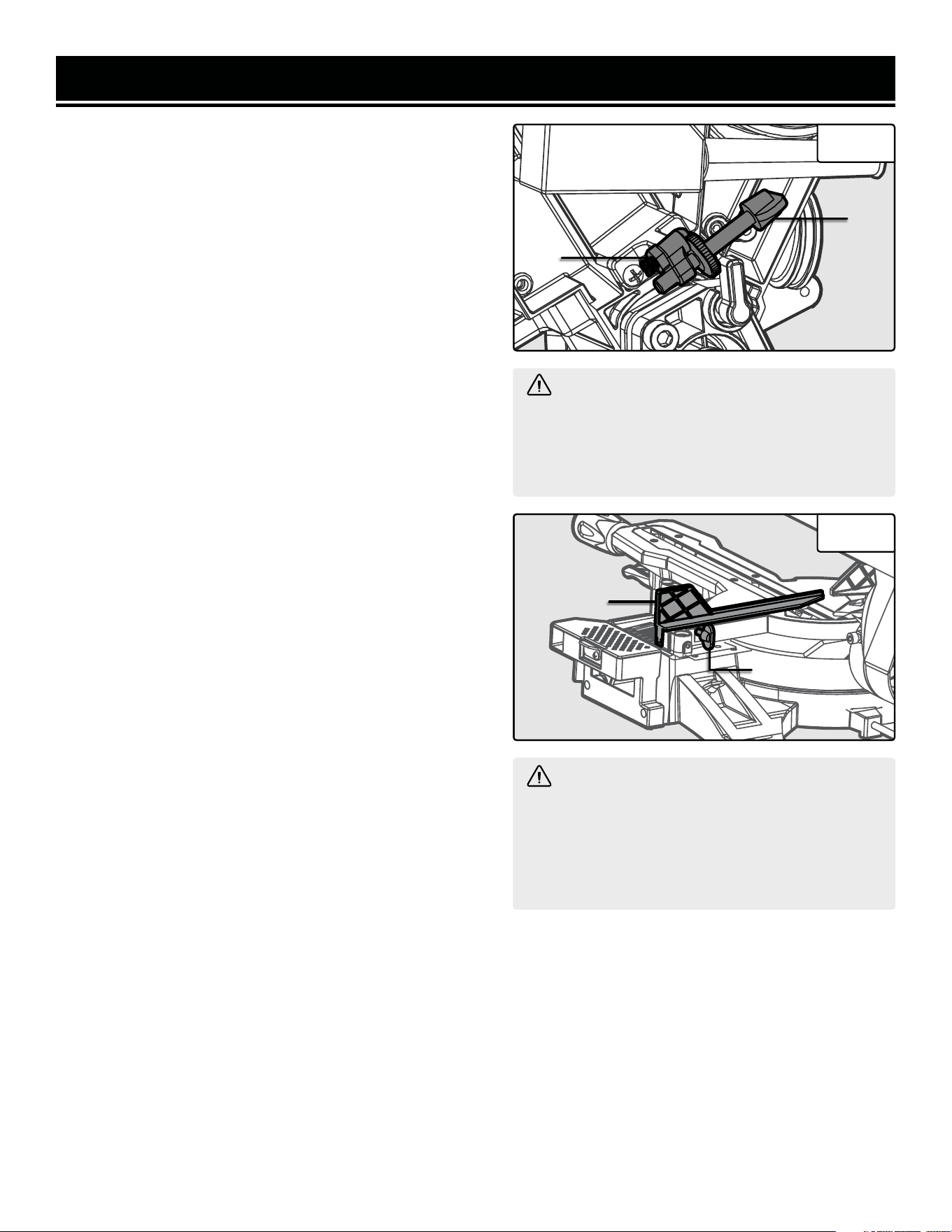
INSTALLING THE BLADE
1. Carefully remove the blade from the packaging.
2. Holding the operating handle, lightly press down on the
saw arm and pull the saw arm release pin (Fig. 1 - 1). Twist
the release pin clockwise and let the saw arm rest in the up-
per position. Use a Phillips-head screwdriver (not included)
to loosen the blade guard screw (Fig. 2 - 1) that holds the
blade guard plate in place. Raise the lower blade guard (Fig.
2 - 2) and the blade guard plate so that you can access the
arbor hex bolt.
3. Firmly press down the saw spindle lock (Fig. 1 - 2). Use
the included 6mm hex wrench to turn the arbor bolt (Fig. 3
- 1) clockwise and remove it (the bolt is left-hand threaded).
Remove the washer and outer flange. Make sure the inner
flange stays in place on the arbor.
4. Place the blade onto the stepped shoulder of the inner
flange. Replace the outer flange, washer, and arbor bolt.
Tighten the arbor bolt while holding down the spindle lock
(Fig. 1 - 2).
IMPORTANT! Make sure the blade's rotation arrow points in
the same direction as the rotation arrow on the upper blade
guard (Fig. 2 - 3).
5. Lower the blade guard, making sure that the blade guard
is properly lowered and covering the arbor bolt. Replace the
blade guard plate and tighten the blade guard screw. Make
sure that the blade guard moves freely and covers the en-
tirety of the blade.
6. Allow the lower blade guard to return back into position.
IMPORTANT! Carefully rotate the saw blade and make sure
that it does not wobble. Lower the saw arm and check that
the blade does not contact the kerf board with the saw at 0°
and 45° bevel angles. Make sure the lower blade guard oper-
ates properly before using the saw.
WARNING! Do not plug in or turn on the tool until it is fully assembled according to the instructions. Read
through and become familiarized with the following procedures of handling and adjusting your miter saw. Failure
to follow the safety instructions may result in serious personal injury.
Fig. 1
2
1
Fig. 3
1
Fig. 2
1
2
3
11
Fig. A
ASSEMBLY & ADJUSTMENTS
RAISING/LOWERING THE SAW ARM
The saw arm needs to be raised up before operation and
locked down for transporting and storing.
To raise saw arm from the lower position:
1. Holding the operating handle (Fig. 4 - 1), lightly press
down on the saw arm and pull out the release pin (Fig. 4
- 2). While pulled out, turn the release pin 90 degrees so it
remains locked in the outer position.
2. Slowly raise the saw arm to the upper position.
To lower saw arm from the upper position:
1. Holding the operating handle (Fig. 4 - 1), pull out the re-
lease pin (Fig. 4 - 2).
2. Slowly lower the saw arm to the lower position and twist
the release pin clockwise until it locks the arm in place.
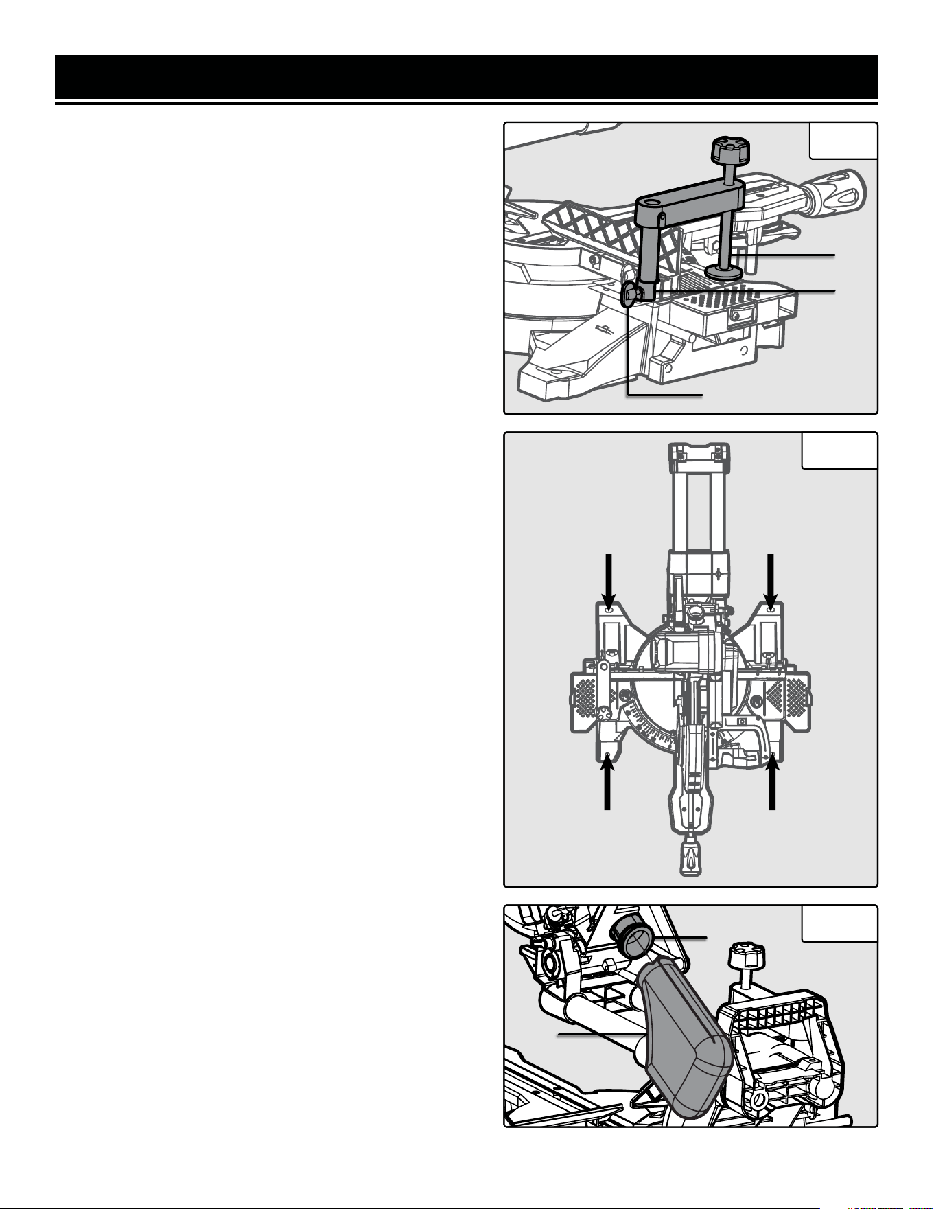
ADJUSTING THE BEVEL ANGLE
The saw arm can bevel from 0° to 45° to the left and right.
1. As viewed from the rear of the saw, loosen the bevel lock
knob (Fig. 5 - 1) by turning it counterclockwise. This will al-
low the saw to bevel to the left.
2. To bevel the saw to the right, pull the right bevel stop pin
out (Fig. 5 - 2). Push the pin back into place once you are
finished with your right bevel cut.
2. The saw is equipped with three bevel adjustment bolts
to provide positive stops at specific bevel angles. The top
right bolt (Fig. 5 - 3) provides a positive bevel angle stop at
45-degrees to the right. The top left bolt (Fig. 6 - 1) provides
a positive bevel angle stop at 45-degrees to the left. The bot-
tom bolt (Fig. 6 - 2) provides a positive bevel angle stop at
0-degrees.
NOTE: The bevel adjustment bolts have been calibrated at
the factory. If adjustments are required, refer to the instruc-
tions on p. 16.
3. Tilt the saw arm until the bevel angle indicator (Fig. 7 - 1)
points to the desired angle on the bevel scale.
4. Tighten the bevel lock knob by turning it clockwise. Be
sure to tighten firmly without over-tightening.
1
2
Fig. 4
Fig. 6
1
2
12
3
1
Fig. 5
2
GUARD OPERATION
NOTE: Keep hands clear of the blade when the operating handle is lowered. Do not interfere with the proper move-
ment of the blade guard. When the handle is lowered, the blade guard raises automatically. When the handle is
raised, the blade guard returns to its safety position, covering the blade.
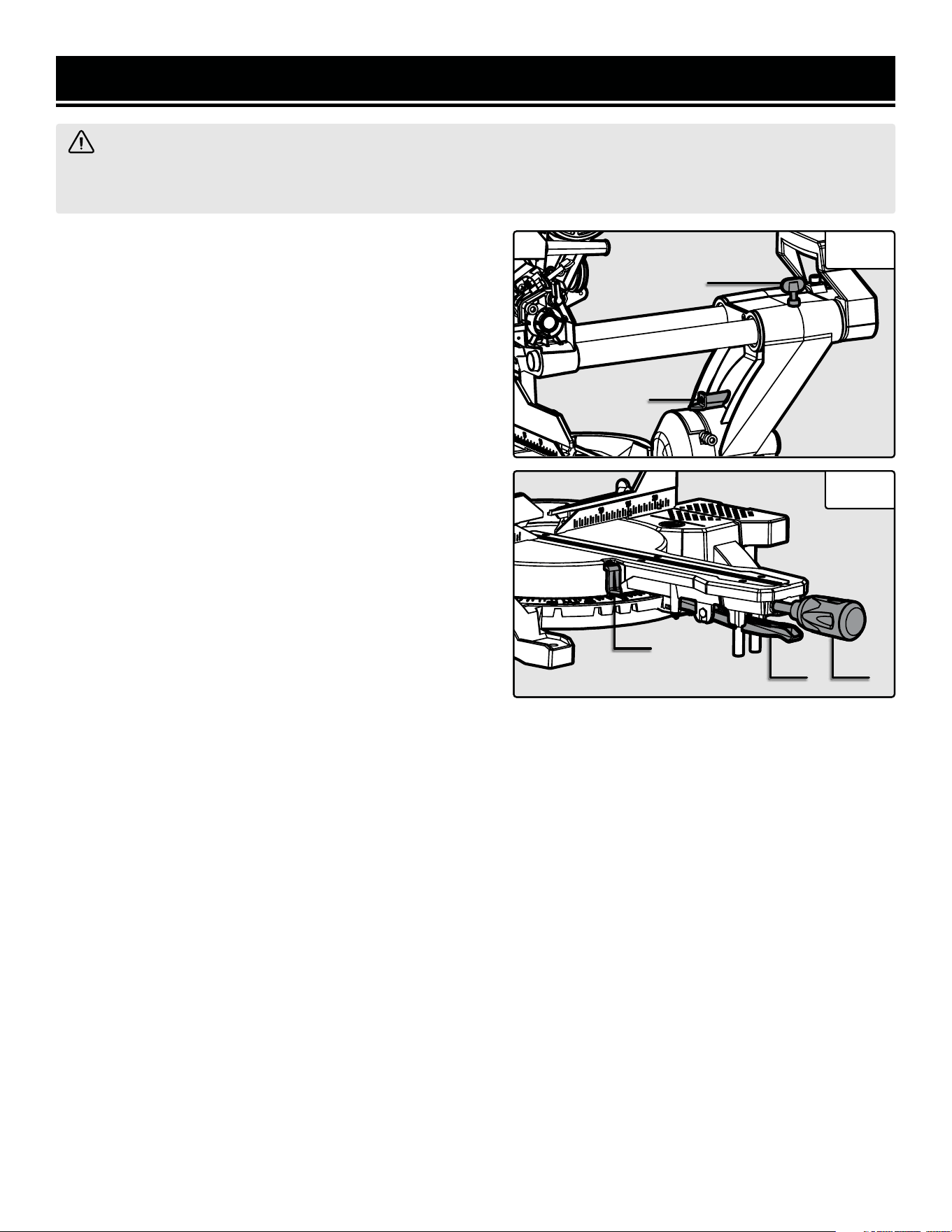
SETTING UP ARM SLIDE
The saw arm can be adjusted to different lengths using the
slide bar, and can slide back and forth when cross-cutting.
For sliding cuts: Loosen the sliding bar lock knob (Fig. 7 - 2)
and slide the saw arm to the desired position.
For non-sliding cuts and transportation: Tighten the sliding
bar lock knob for non-sliding operations and before trans-
porting the miter saw.
ADJUSTING THE MITER ANGLE
The miter table can be adjusted from 0° to 45° in either di-
rection to create miter cuts.
1. Loosen the miter lock knob (Fig. 8 - 1) by turning it coun-
terclockwise.
2. Pull up on the miter stop lever (Fig. 8 - 2) to unlock the
table. While holding the miter angle adjustment lever up, ad-
just the table to the desired angle. The miter scale indicator
(Fig. 8 - 3) will point towards the selected angle. To make
micro adjustments to a specific angle, rotate the table while
pulling up on the miter stop lever. The miter table has posi-
tive stops at 0°, 15°, 22.5°, 30°, and 45° in both directions
for quick adjustments.
3. After selecting your miter angle, release the miter stop
lever and tighten the miter lock knob by turning it clockwise
to lock the table in place.
WARNING! Be sure the miter table is locked in place before
making a cut. Failure to do so can cause the table to move
during the cut, which could result in serious personal injury.
ASSEMBLY & ADJUSTMENTS
WARNING! Do not plug in or turn on the tool until it is fully assembled according to the instructions. Read
through and become familiarized with the following procedures of handling and adjusting your miter saw. Failure
to follow the safety instructions may result in serious personal injury.
2
Fig. 7
1
Fig. 8
3
2 1
13
ASSEMBLY & ADJUSTMENTS
INSTALLING THE CLAMP ASSEMBLY
The included workpiece clamp can be mounted on the left or
right side of the saw depending on the cutting task at hand.
1. Locate the hole for the clamp (Fig. 9 - 1) on the left or right
side of the miter saw behind the fence. Insert the clamp as-
sembly (Fig. 9 - 2) into the hole on the desired side.
2. Secure the clamp into place by tightening the clamp lock
knob (Fig. 9 - 3).
NOTE: Check that the clamp won’t interfere with the blade
travel before operating the saw.
BENCH MOUNTING
The miter saw has four holes on the base for bench mount-
ing (Fig. 10). Mount and fix the saw to a level, horizontal
bench, worktable, or miter saw stand (compatible with WEN
models MSA200, MSA330, and MSA750T) using four bolts
and nuts (not included).
If desired, you can mount the saw to a piece of 1/2 inch or
thicker plywood which can then be clamped to your work
bench or moved to other jobsites and reclamped.
CAUTION! Make sure that the mounting surface is not
warped. Uneven surfaces can cause binding and inaccurate
sawing.
INSTALLING THE DUST COLLECTION BAG
The dust collection bag should be used at all times. Follow
the instructions below to install the bag:
1. Locate the dust port (Fig. 11 - 1) on the back of the miter
saw.
2. Slip the mouth of the dust collection bag (Fig. 11 - 2) over
the dust port. Make sure that it is secured in place.
3. Open the zipper on the bottom of the bag to empty. For
efficient operation, empty the dust bag when half full to allow
for better air flow through the bag.
4. If desired, use a dust port adapter (not included) to con-
nect to a dust extraction system. If needed, use a hose clamp
to tightly clamp the dust hose to the adapter.
• The outer diameter of the dust port tube is
1.55 in.
(39.50mm).
• The inner diameter of the dust port is
1.28 in. (32.5mm).
Fig. 10
Fig. 11
1
2
14
Fig. 9
1
2
3
2
ASSEMBLY & ADJUSTMENTS
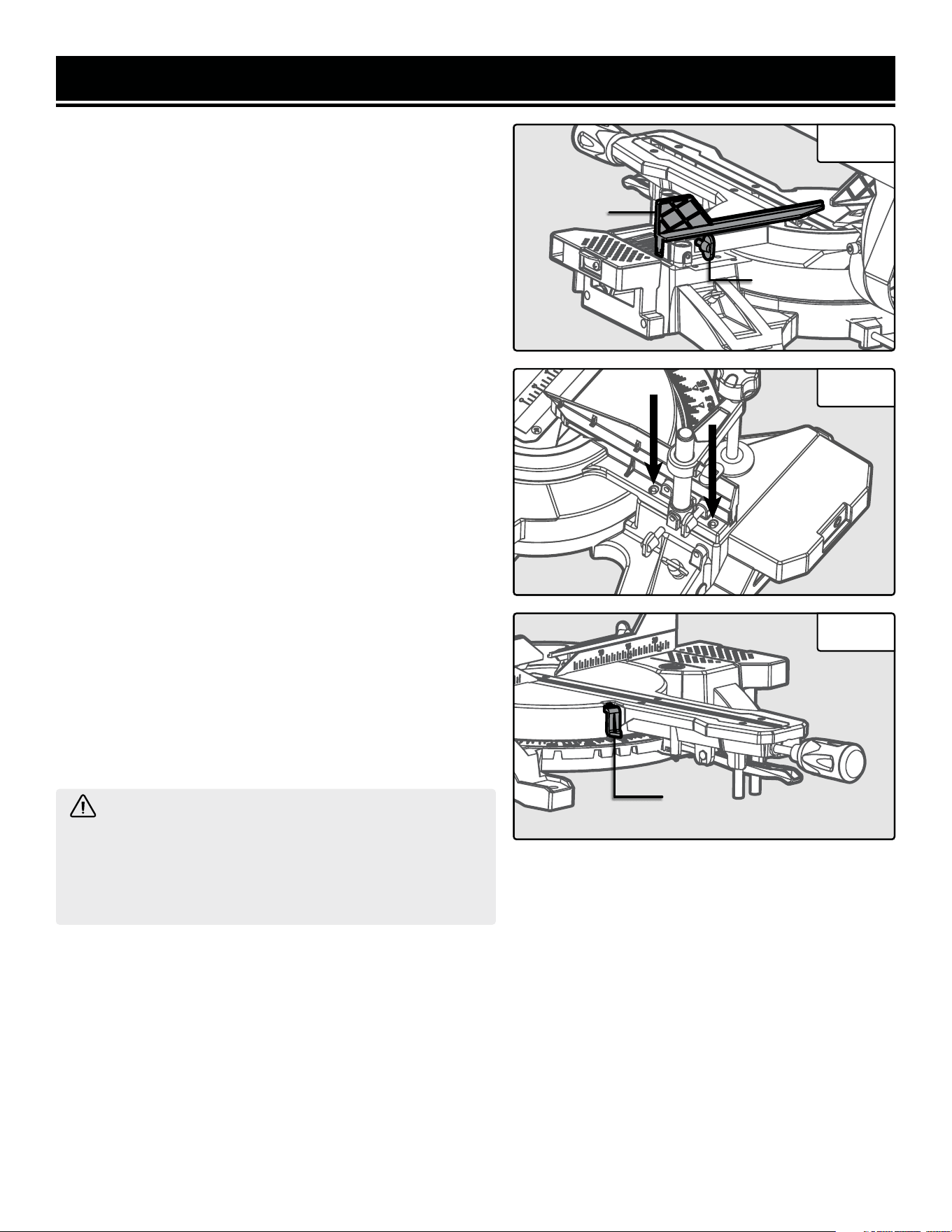
SQUARING THE FENCE WITH THE BLADE
To make accurate cuts, the fence must be perpendicular to
the saw blade.
1. Lower the saw arm down to the lower position and lock
the release pin.
2. Slide the saw arm to the back and tighten the slide lock
knob.
3. Set the miter scale indicator to 0° and tighten the miter
lock knob. Place a combination square (not included) against
the fence and alongside the saw blade (should be in contact
with the surface of the blade, not the teeth).
4. Fully loosen the two fence adjustment knobs (Fig. 12 - 1)
and remove both fence guides (Fig. 12 - 2). There are four
socket-head screws (2 on either side) that hold the fence base
to the saw base (Fig. 13). Using the included hex wrench,
loosen these four screws and adjust the fence position until
it is 90º with the blade. Tighten the four screws, replace the
fence guides, and secure the fence adjustment knobs.
5. Make a test cut. Repeat step 4 until your test cut is ac-
curate.
SETTING THE MITER SCALE INDICATOR
1. Loosen the screw holding the miter scale indicator (Fig.
14 - 1).
2. Adjust direction of the indicator so that it accurately points
to 0° on the miter scale. Tighten the screw.
WARNING: To prevent serious injury, after making
any adjustments to the cutting angle, make sure both
sides of the fence are clear of the blade's cutting path.
With the power OFF, move the blade through its full range
of motion to check this.
Fig. 12
Fig. 13
Fig. 14
1
1
15
2
1
ASSEMBLY & ADJUSTMENTS
SQUARING THE TABLE WITH THE BLADE
To make accurate cuts, the table must be perpendicular to
the saw blade.
1. Lower the saw arm down to the lower position and lock
the release bolt.
2. Slide the saw arm to the back and tighten the slide lock
knob.
3. Set the miter scale indicator to 0° and tighten the miter
lock knob. Set the bevel angle indicator to 0° and tighten the
bevel lock knob.
4. Place a combination square (not included) against the
table and alongside the saw blade (should be in contact with
the surface of the blade, not the teeth). Wearing work gloves,
rotate the blade by hand and check the blade-to-table align-
ment at several points. The edge of the combination square
and the saw blade should be parallel. If the saw blade does
not lay flush against the combination square, follow steps 5
& 6 below:
5. Adjust the zero stop screw (Fig. 15 - 1) until the table is
90° with the blade. Tighten the zero stop lock nut to secure
the blade.
6. Make a test cut. Repeat step 5 until test cut is accurate.
7. Repeat steps 3 - 6 with the bevel setting at 45°. Adjust the
left 45-degree stop screw (Fig. 15 - 2) or right 45-degree
stop screw (Fig. 16 - 1) until the table is at 45° relative to
the blade.
SETTING THE BEVEL SCALE INDICATOR
1. Before setting the bevel scale indicator, the table must be
perpendicular to the saw blade. See previous section.
2. Loosen the screw holding the bevel scale indicator (Fig.
17 - 1).
3. Adjust the direction of the indicator so that it accurately
points to 0° on the bevel scale. Tighten the screw.
Fig. 15
Fig. 17
1
Fig. 16
1
16
2
1
2
ASSEMBLY & ADJUSTMENTS
ADJUSTING THE CUTTING DEPTH
The saw cutting depth can be adjusted if you would like to
perform a kerfing or rabbet cut that does not cut all the way
through the workpiece.
1. Unplug the tool from its power source and raise the saw
head assembly.
2. Locate the depth stop settings on the right side of the saw
(Fig. 18).
3. Pull down on the saw head to check the current setting. To
change the setting, continue to step 4.
4. Loosen the depth stop knob (Fig. 18 - 1). To increase
depth, turn the depth stop knob counterclockwise. To de-
crease depth, turn the depth stop knob clockwise. Tighten
the nut on the depth stop knob once the desired depth is
reached.
5. Check that the blade will not hit the table, fence, kerf board,
or other part of the saw during the cut. Check the cutting
depth setting by completing a test cut on a piece of scrap
wood. Repeat steps 4 - 5 until the desired depth is achieved.
ADJUSTING THE FENCE
1. Loosen the fence adjustment knob (Fig. 19 - 1).
2. Adjust the fence as desired. The top portion of the fence
(Fig. 19 - 2) can slide to the left and right, while the bottom
portion of the fence stays stationary.
3. Tighten the fence adjustment knob to lock the fence into
place.
WARNING: DO NOT adjust the depth stop
screw (Fig. 18 - 2)
.
Only adjust the depth stop
knob. The depth stop screw is used to prevent
the blade from cutting the table during normal
cutting. DO NOT adjust the depth stop screw.
WARNING: To prevent serious injury, after
making any adjustments to the cutting angle,
make sure both sides of the fence are clear of
the blade's cutting path. With the power OFF,
move the blade through its full range of motion
to check this.
Fig. 18
Fig. 19
1
17
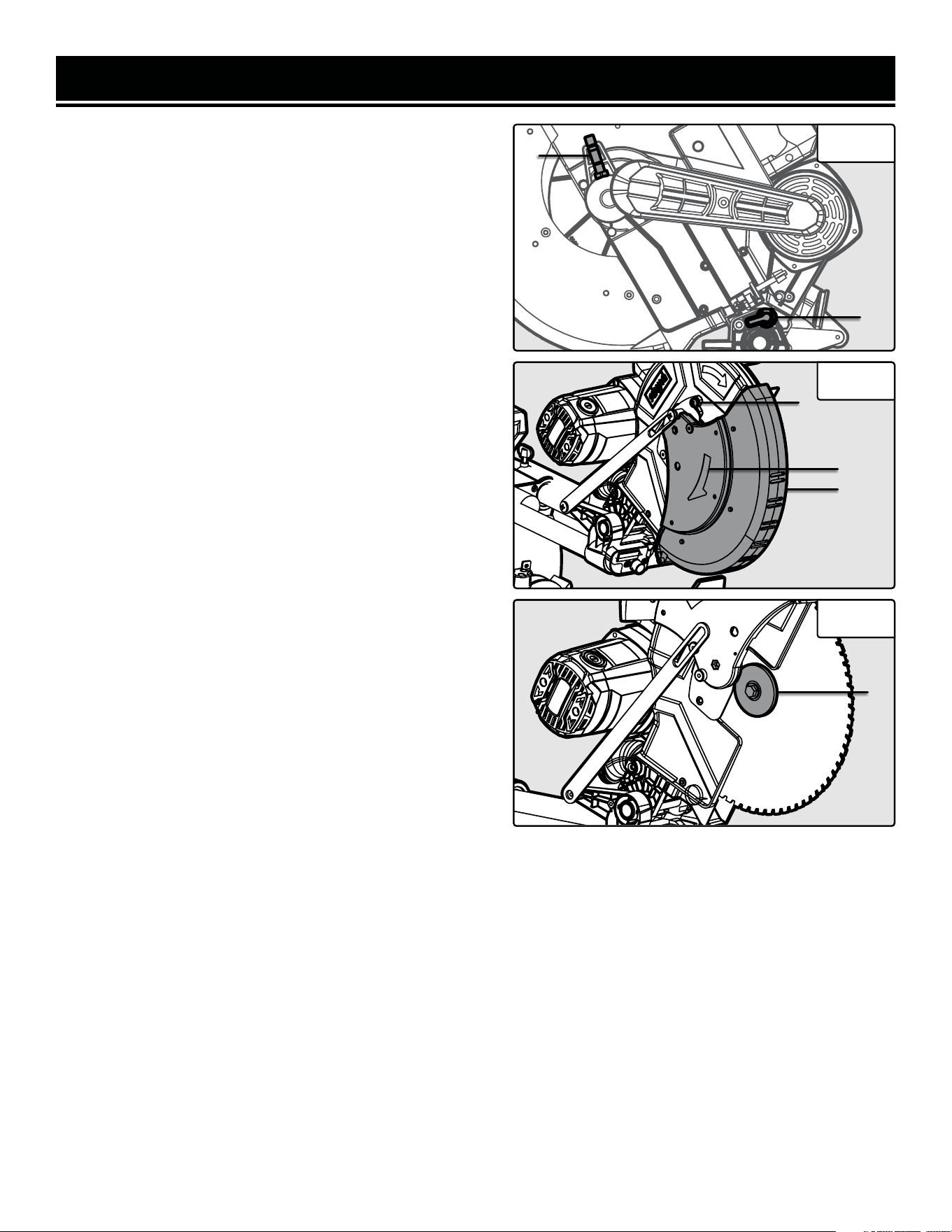
ASSEMBLY & ADJUSTMENTS
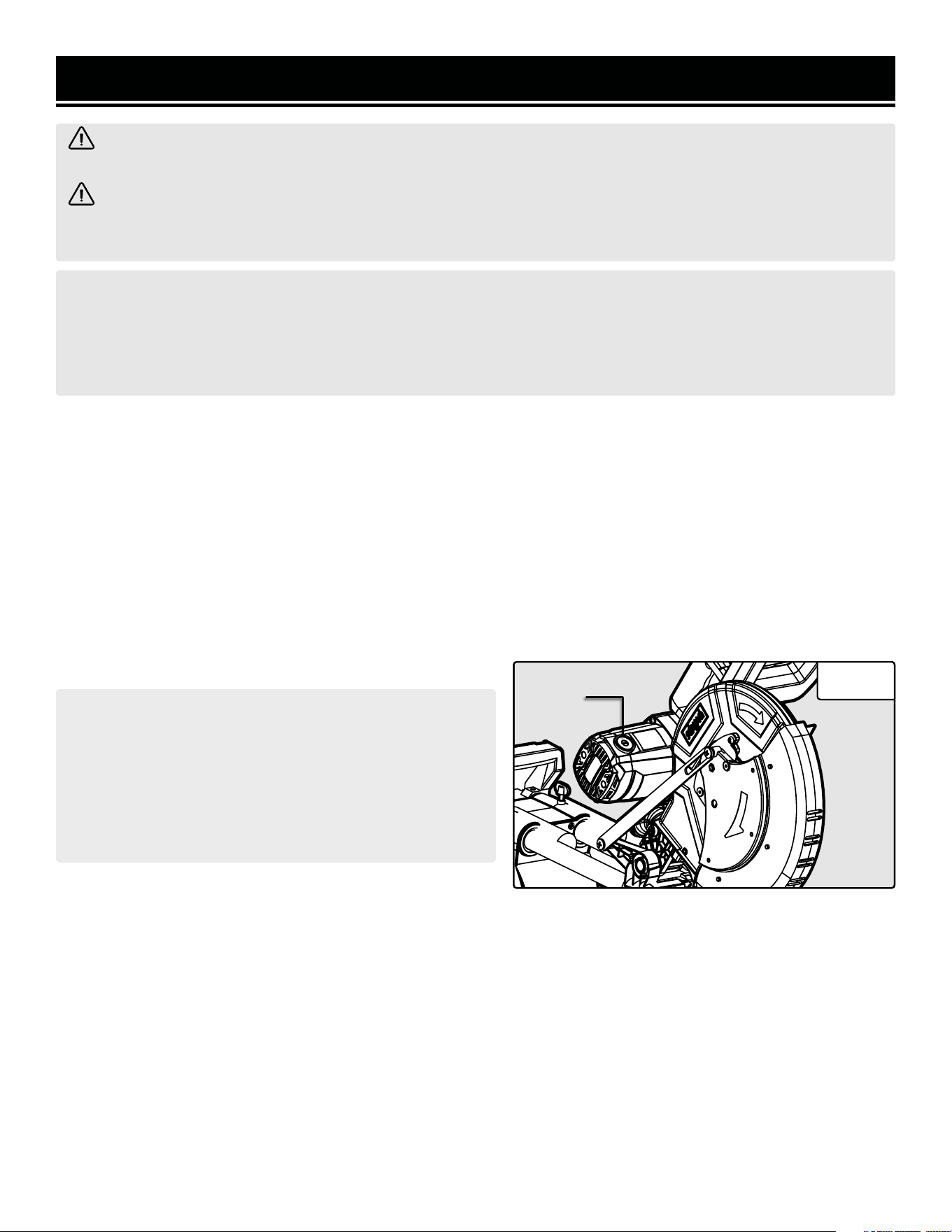
CHANGING THE SAW BLADE
DANGER! Never try to use a blade larger than the stated ca-
pacity of the saw. Do not use a blade thicker than 1.8mm.
It will prevent the blade screw from properly securing the
blade on the spindle. Install the suitable blade for your cut-
ting operation.
1. Unplug the tool from its power source.
2. Pull out the saw arm release pin (Fig. 20 - 1) and let the
saw arm rest in the upper position. Use a Phillips-head
screwdriver (not included) to loosen the blade guard screw
(Fig. 21 - 1) that holds the blade guard plate in place. Raise
the lower blade guard (Fig. 21 - 2) and the blade guard plate
so that you can access the arbor hex bolt (Fig. 22 - 1).
3. Firmly press down the saw spindle lock (Fig. 20 - 2) below
the operating handle and hold it in. Use the included 6mm
hex wrench to turn the arbor bolt clockwise and remove it
(the bolt is left-hand threaded). Remove the washer and
outer flange. Make sure the inner flange stays in place on
the arbor.
4. Slowly remove the blade by pulling it out and down. Clean
the arbor bolt, washer, and outer flange.
5. Place the new blade onto the stepped shoulder of the in-
ner flange. Replace the outer flange, washer, and arbor bolt.
Tighten the arbor bolt while holding down the spindle lock
(Fig. 20 - 2).
IMPORTANT: Make sure the blade's rotation arrow points in
the same direction as the rotation arrow on the upper blade
guard.
6. Lower the blade guard, making sure that the blade guard
is properly lowered and covering the arbor bolt. Reinstall the
blade guard screw. Make sure that the blade guard moves
freely and covers the entirety of the blade.
7. Allow the lower blade guard to return back into position.
IMPORTANT: Carefully rotate the saw blade and make sure
that it does not wobble. Lower the saw arm and check that
the blade does not contact the kerf board, with the saw at 0°
and 45° bevel angles. Make sure the lower blade guard oper-
ates properly before using the saw.
1
1
1
2
3
Fig. 20
Fig. 21
Fig. 22
2
18
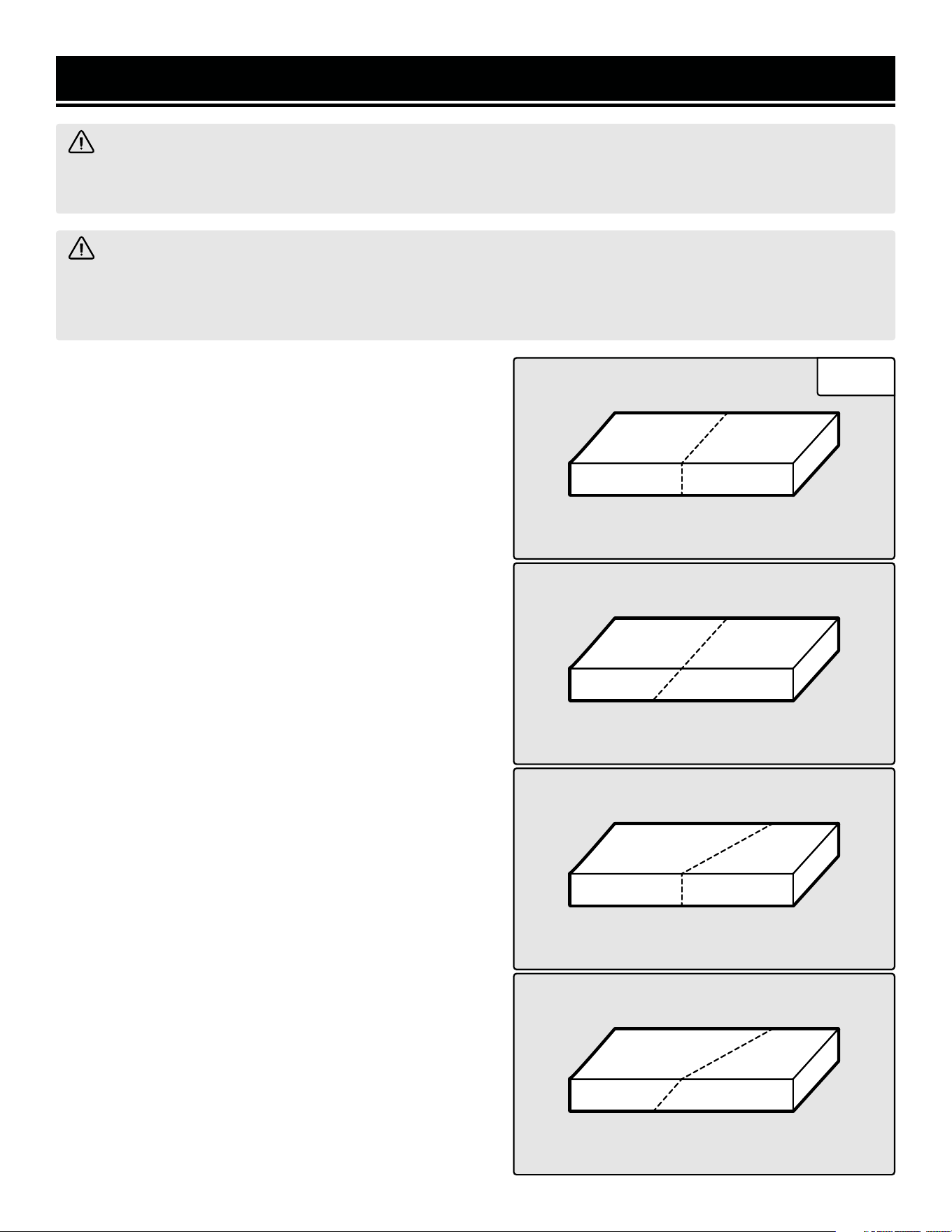
CROSS CUT
Miter table 0°, Saw arm 0°
OPERATION
1. RAISE THE SAW ARM
Before operation, raise the saw arm from the lower position.
See section titled, "RAISING / LOWERING THE SAW ARM".
2. SET UP THE CUT ANGLE & DEPTH
The miter saw can be set up to create cuts at different angles
by adjusting the angle of the miter table and the saw bevel
angle. There are four types of cuts you can create: a cross
cut, a miter cut, a bevel cut, and a compound cut. See Fig.
23 to understand each type of cut. If you do not want to cut
all the way through your workpiece, adjust the cutting depth.
See note below.
To adjust the bevel angle: see section titled, "ADJUSTING
THE BEVEL ANGLE".
To adjust the miter angle: see section titled, "ADJUSTING
THE MITER ANGLE".
To adjust the cutting depth: see section titled, "ADJUSTING
THE CUTTING DEPTH".
3. SET UP SLIDING FUNCTION
For materials with a width under 2-1/2 inches (63mm): The
sliding function isn’t necessary. See section titled, "SETTING
UP ARM SLIDE" to disable the sliding function.
For materials with a width over 2-1/2 inches (63mm): The
saw arm will need to slide to cut through the workpiece. See
section titled, "SETTING UP ARM SLIDE" to enable the slid-
ing function.
WARNING! Do not plug in or turn on the tool until it is fully assembled according to the instructions. Read
through and become familiarized with the following procedures of handling and adjusting your tool. Failure to
follow the safety instructions may result in serious personal injury.
WARNING! Before operating the miter saw, make sure to equip yourself with a dust mask, ear protection,
and safety glasses for protection from possible injuries. Tie back long hair and do not wear loose clothing or
jewelry. DO NOT look into the laser beam, this can cause serious eye damage or blindness. Do not wear gloves
while operating the saw.
Fig. 23
BEVEL CUT
Miter table 0°, Saw arm 0° - 45°
MITER CUT
Miter table 0° - 45°, Saw arm 0°
COMPOUND CUT
Miter table 0° - 45°, Saw arm 0° - 45°
19
OPERATION
WARNING! Do not plug in or turn on the tool until it is fully assembled according to the instructions. Read
through and become familiarized with the following procedures of handling and adjusting your tool. Failure to
follow the safety instructions may result in serious personal injury.
WARNING! Before operating the miter saw, make sure to equip yourself with a dust mask, ear protection,
and safety glasses for protection from possible injuries. Tie back long hair and do not wear loose clothing or
jewelry.
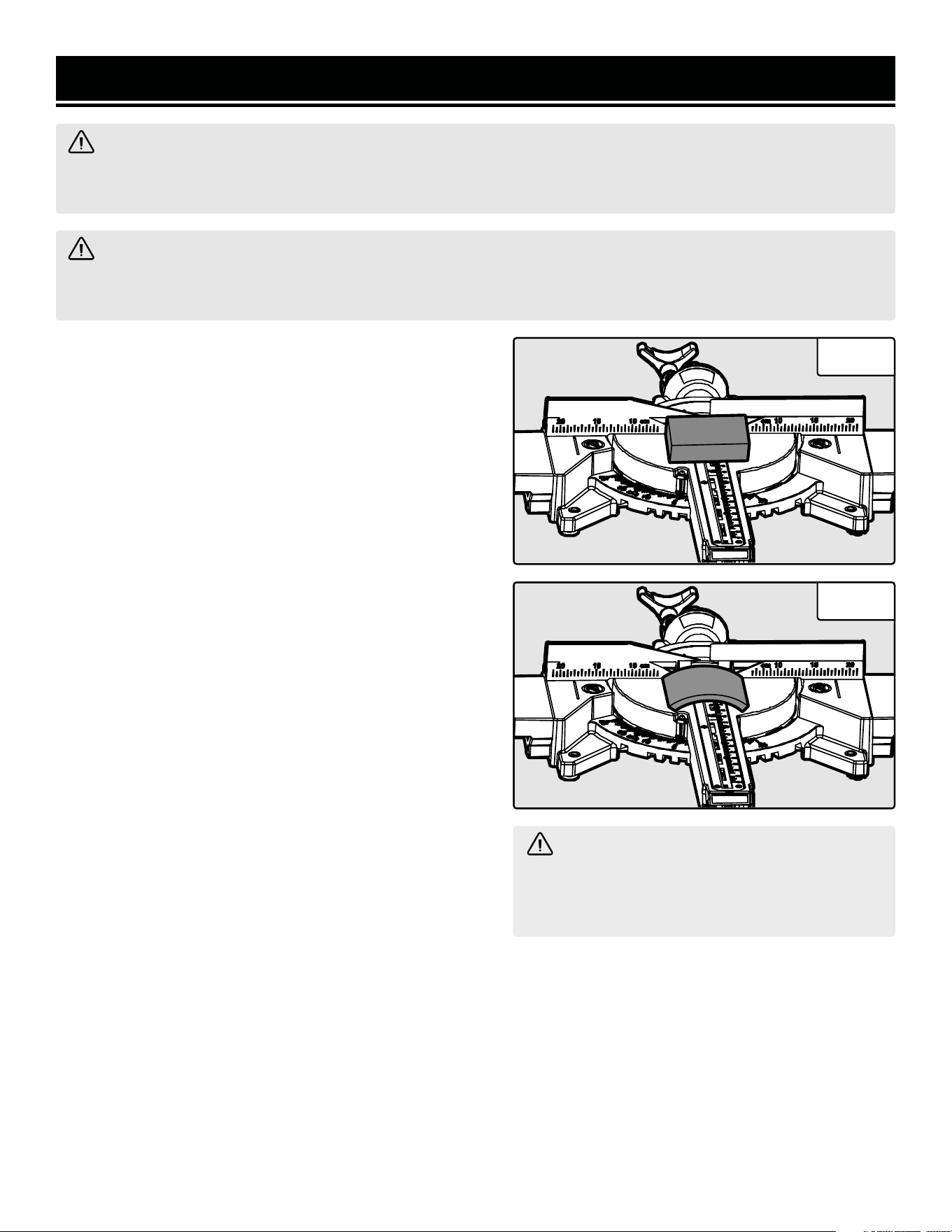
4. SET UP WORKPIECE
Place the workpiece flat on the table with one edge securely
against the fence (Fig. 24).
Warped Boards: If the board is warped, place the concave
side against the table (Fig. 25). CAUTION: The board could
break and jam the blade if the convex side is placed against
the table.
Long Boards: When cutting long workpieces, support the
opposite end of the material with the support bars, a roller
stand, or a work surface that is level with the saw table.
5. SECURE WORKPIECE
Secure the workpiece with the hold-down clamp on the fixed
table whenever possible to prevent the material from mov-
ing during the cutting operations. See section, "Installing the
Clamp Assembly" on page 13.
6. CHECK BEFORE OPERATION
• Check that the miter table does not rotate and the saw
arm does not bevel.
• Check that the workpiece is fully supported, against the
fence and securely clamped down.
• Check that you have the proper blade for the material you
are cutting.
• Without turning on the saw, perform a dry run of the
cutting operation to check that nothing is obstructing the
path of the saw.
Fig. 24
Fig. 25
WARNING: Be sure to tighten the miter lock
and bevel lock before making a cut. Failure to do
so could result in the table moving during the cut
and may cause serious personal injuries.
20
OPERATION
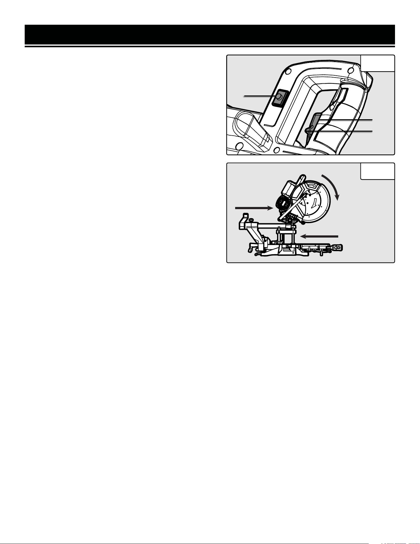
7. PERFORM THE CUT
1. Plug in the miter saw. Turn on the laser power switch
(Fig. 26 - 1) to see where your cut will land on the material.
CAUTION: DO NOT look into the laser light or point it at any
living thing.
2. Grip the operating handle firmly, press in the power switch
lock (Fig. 26 - 2) and squeeze the power trigger (Fig. 26 - 3)
to turn the saw ON.
3. Allow the blade to reach full speed. Make sure the work-
piece is held securely against the table and fence at all times.
If the material binds the blade, release the power trigger.
• For non-sliding cuts: Slowly lower the blade into and
through the workpiece.
• For sliding cuts: Pull the saw arm all towards the front of
the machine. Slowly lower the blade into the workpiece
while steadily pushing it away from you until the work-
piece is cut (Fig. 27). CAUTION: Never slide the saw arm
towards yourself while cutting. Always push away.
4. Release the power trigger and wait until the blade fully
stops before raising it from the workpiece.
5. Unplug the miter saw before leaving your work station.
Clean your work station and store tools out of reach of chil-
dren.
Fig. 26
Fig. 27
1
1. Pull1. Pull
ForwardForward
2. Lower2. Lower
BladeBlade
3. Push Back3. Push Back
to Cutto Cut
2
3
21
22
MAINTENANCE
WARNING! To avoid accidents, turn OFF and unplug the tool from the electrical outlet before cleaning,
adjusting, or performing any maintenance work.
WARNING! Any attempt to repair or replace electrical parts on this tool may be hazardous. Servicing of the
tool must be performed by a qualified technician. When servicing, use only identical WEN replacement parts.
Use of other parts may be hazardous or induce product failure.
NOTE: Electric tools used on fiberglass material, wallboard, spackling compounds, or plaster are subject to ac-
celerated wear and possible premature failure because the fiberglass chips and grindings are highly abrasive to
bearings, brushes, commutators, etc. Consequently, we do not recommend using this tool for extended work on
these types of materials. However, if you do work with any of these materials, it is extremely important to clean
the tool using compressed air after operation.
ROUTINE INSPECTION
Before each use, inspect the general condition of the tool. If
any of these following conditions exist, do not use until parts
are replaced or the saw is properly repaired.
Check for:
• Loose hardware
• Misalignment or binding of moving parts
• Damaged cord/electrical wiring
• Cracked or broken parts
• Any other condition that may affect its safe operation
CLEANING & STORAGE
CAUTION! Most plastics are susceptible to damage from
various types of commercial solvents. Do not use any
solvents or cleaning products that could damage the
plastic parts. Some of these include but are not limited
to: gasoline, carbon tetrachloride, chlorinated cleaning
solvents, and household detergents that contain ammo-
nia.
1. Keep the ventilation openings free from dust and debris to
prevent the motor from overheating.
2. Wipe the tool surfaces clean with a clean cloth. Make sure
water does not get into the tool.
3. Store the tool in a clean and dry place away from the reach
of children. Store in temperatures between 41° to 86°F.
4. Cover the miter saw in order to protect it from dust and
moisture. It is preferable to store it in its original packaging
with the instruction manual and all accessories.
LUBRICATION
The bearings of your miter saw are permanently
sealed and require no extra lubrication. The gearbox
is also sufficiently lubricated from the factory and
requires no additional lubrication.
CARBON BRUSH REPLACEMENT
Replacement carbon brushes (Part No. MM1213-
223) can be ordered at wenproducts.com. Only gen-
uine WEN replacement brushes designed specifically
for your tool should be used. Carbon brushes are not
covered under the two-year warranty.
Fig. 28
1. To access the carbon brushes, remove the carbon
brush cap (Fig. 28 - 1) on the underside of the motor
housing.
2. Carefully remove the old carbon brushes using
pliers.
3. Install the new carbon brushes. Both carbon
brushes should be replaced at the same time. Re-
place the motor end cap.
NOTE: New carbon brushes tend to spark for a few
minutes during the first use as they wear down.
1

23
MAINTENANCE
PRODUCT DISPOSAL
Used power tools should not be disposed of together with household waste. This product contains electronic com-
ponents that should be recycled. Please take this product to your local recycling facility for responsible disposal and
to minimize its environmental impact.
Please recycle the packaging and electronic components where facilities exist.
WARNING! Stop using the tool immediately if any of the following problems occur. Repairs and replacements
should only be performed by an authorized technician. For any questions, please contact our customer service
at 1-847-429-9263, M-F 8-5 CST or email us at [email protected].
PROBLEM CAUSE SOLUTION
Ineffective cutting
performance.
1. Blade is dull. 1. Sharpen or replace blade.
2. Blade is dirty.
2. Remove the blade and clean the surface and
cutting edge with steel wool and turpentine.
3. The blade is not secure.
3. Make sure the blade flanges are flush against
the blade and arbor bolt is tightened completely.
4. Incorrect blade used for
workpiece.
4. Ensure the blade is compatible with the
material type and thickness being cut.
5. Blade is installed improperly. 5. Ensure blade is installed in correct orientation.
Excessive noise or
vibration.
1. Not mounted properly.
1. Make sure the saw is mounted securely to a
flat and level work surface.
2. Blade is damaged. 2. Replace blade.
3. Blade is not secure.
3. Make sure the blade flanges are flush against
the blade and arbor bolt is tightened completely.
Blade will not turn.
1. Excessive sawdust or chips
between blade and frame.
1. Clean the space between the blade and frame
with compressed air and ensure no chips are
stuck within.
2. Spindle lock is engaged.
2. Disengage the spindle lock; move blade back
and forth to ensure it is disengaged.
TROUBLESHOOTING GUIDE

PROBLEM CAUSE SOLUTION
Motor does not start.
1. Power cord damaged or not
properly plugged in.
1. Check the power cord, extension cord, power
plug, and the power outlet. Do not use the
tool if any cord is damaged.
2. Defective power switch.
2. Stop using the tool and call 1-847-429-9263
for customer service.
3. Insufficient power from power
outlet.
3. Make sure the outlet is functional and is the
right capacity for the tool.
4. Worn carbon brushes.
4. Inspect and replace carbon brushes as
needed. Replacement carbon brushes (Part
No. MM1014-111) can be ordered from
wenproducts.com.
5. Defective motor or other
internal problem.
5. Stop using the tool and call 1-847-429-9263
for customer service.
Saw overheats.
1. Tool forced to work too fast.
1. Do not force the tool. Let it work at its own
pace. Ensure blade selection is appropriate for
cut type and workpiece.
2. Wrong extension cord gauge.
2. Select proper extension cord. Refer to
"ELECTRICAL INFORMATION".
3. Blocked motor housing vents.
3. Wear safety glasses & dust mask. Blow dust
out of motor housing vents.
WARNING! Stop using the tool immediately if any of the following problems occur. Repairs and replacements
should only be performed by an authorized technician. For any questions, please contact our customer service
at 1-847-429-9263, M-F 8-5 CST or email us at [email protected].
TROUBLESHOOTING GUIDE
24
25
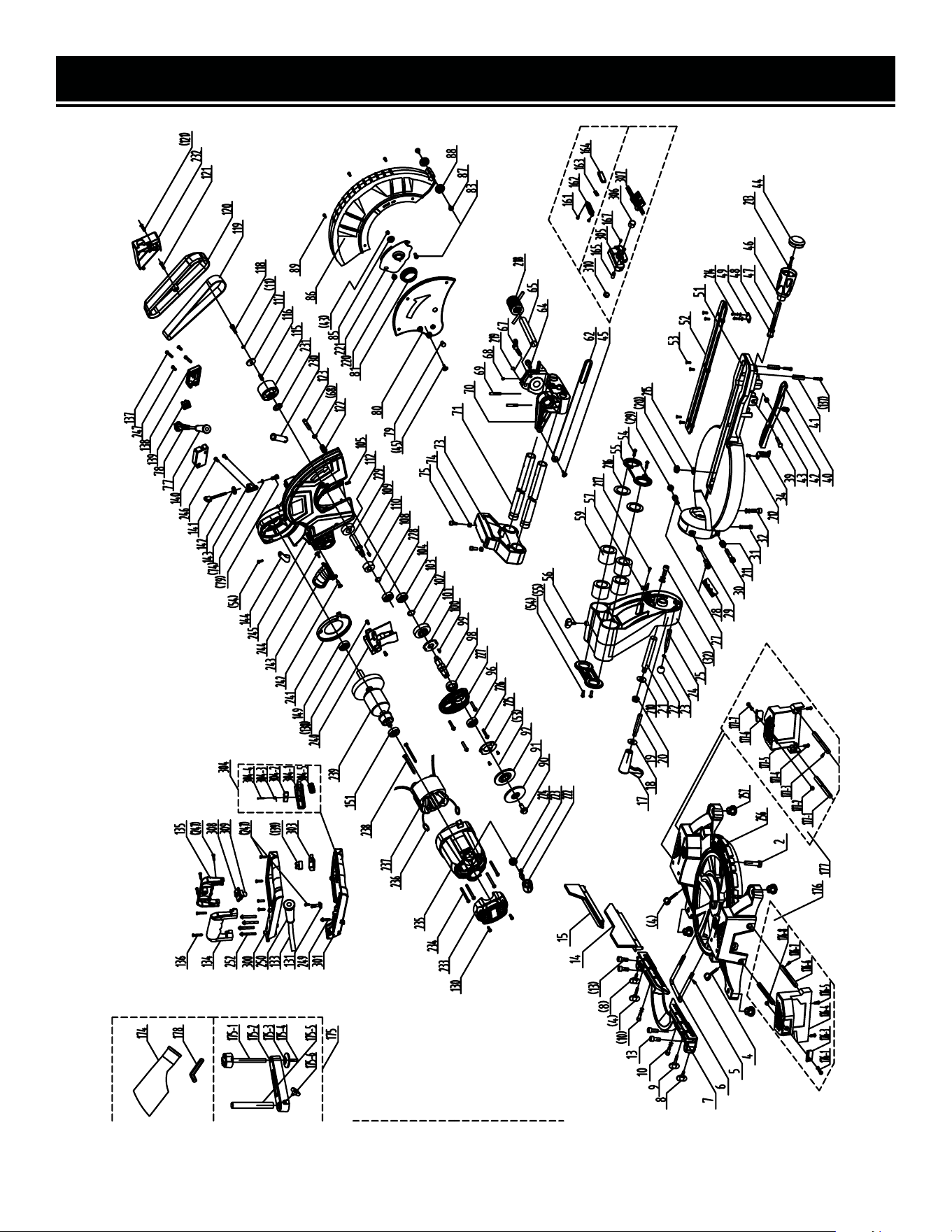
EXPLODED VIEW & PARTS LIST
左护翼
右护翼
LED
激光
夹
紧
杆
NOTE: Not all parts may be available for purchase. Parts and accessories that wear
down over the course of normal use are not covered under the warranty.

No. Part. No. Description Qty.
2 MM1213-002 Hex Bolt, M10x40 1
4 MM1014-035 Screw Knob, M6x40 3
5 MM1213-005
Phillips-Head Screw,
M4x10
1
6 MM1213-006 Rear Support 1
7 MM1213-007 Fence 1
8 MM1213-008 Screw Knob, M6x8 2
9 MM1014-007 Screw Knob, M6x30 1
10 MM1213-010
Socket Head Cap
Screw, M6x20
2
13 MM1213-013
Socket Head Cap
Screw, M8x20
4
14 MM1213-014 Left Fence Extension 1
15 MM1213-015 Right Fence Extension 1
17 MM1213-017 Bevel Locking Handle 1
18 MM1213-018 Washer, 8x22x2 1
19 MM1213-019 Bevel Axle 1
20 MM1213-020 Lock Nut, M10 2
21 MM1213-021 Locking Axle 1
22 MM1014-062 Round Nut 1
23 MM1213-023 O-ring, 9x2mm 1
24 MM1213-024 Dowel Pin 1
25 MM1213-025 Bevel Arm 1
27 MM1213-027
Socket Head Cap
Screw, M8x25
2
28 MM1213-028 Bevel Scale Label 1
29 MM1014-037 Lock Nut, M8 2
30 MM1213-030
Socket Head Cap
Screw, M8x50
1
31 MM1213-031
Socket Head Cap
Screw, M6x25
1
32 MM1213-032
Socket Head Cap
Screw, M8x25
2
34 MM1213-034 Miter Pointer 1
39 MM1213-039 Hex Bolt, M6x40 1
40 MM1213-040 Locking Lever 1
41 MM1213-041 Support Rod 2
42 MM1014-031 Locking Lever Spring 1
43 MM1014-030 Hex Lock Nut, M6 2
44 MM1213-044 Miter Knob Cap 1
45 MM1014-054
Phillips-head Screw
with Flange, M5x16
2
No. Part. No. Description Qty.
46 MM1213-046ASM Miter Knob 1
47 MM1213-047 Miter Locking Rod 1
48 MM1213-048
Center Slotted Nut,
M10x20
1
49 MM1213-049 Lock Washer 1
51 MM1213-051 Miter Table 1
52 MM1213-052 Table Insert 1
53 MM1213-053 Set Screw, M4x12 9
54 MM1213-054 Phillips Screw, M5x10 5
55 MM1213-055 Rail Cover 2
56 MM1014-007 Screw Knob, M6x30 1
57 MM1213-057 Bevel Pointer 1
59 MM1213-059
Linear Bearing,
30x45x35mm
4
62 MM1213-062 Connecting Rod 1
64 MM1014-038
Socket Head Cap
Screw, M8x30
1
65 MM1213-065 Axle 1
67 MM1213-067 Locking Pin 1
68 MM1213-068 Circlip, 6mm 2
69 MM1213-069 Spring Pin, 6x40mm 2
70 MM1213-070 Pivot Bracket 1
71 MM1213-071 Rail 2
73 MM1213-073 Rear Handle 1
74 MM1014-094 Nut, M6 3
75 MM1213-075
Socket Head Cap
Screw, M6x14
2
77 MM1213-077
Power Cord Strain
Relief
1
78 MM1213-078 Power Cord 1
79 MM1213-079 Hex Bolt, M6x16 2
80 MM1213-080ASM
Blade Guard Cover
Plate Assembly
1
81 MM1213-081
Blade Guard Cover
Spring
1
83 MM1213-083
Phillips Head Screw,
M6x10
1
85 MM1213-085 Sleeve 1
86 MM1213-086 Blade Guard 1
87 MM1213-087
Self-tapping Screw
with Washer, ST4x15
2
88 MM1014-075 Blade Guard Wheel 2
EXPLODED VIEW & PARTS LIST
26

No. Part. No. Description Qty.
89 MM1213-089
Phillips Head Screw,
M4x14
3
90 MM1213-090 Arbor Bolt, M8x20 1
91 MM1213-091 Outer Flange 1
N.P. BL1248 Blade
92 MM1213-092 Inner Flange 1
96 MM1213-096 Ball Bearing, 6003 1
98 MM1213-098 Oil Seal 1
99 MM1213-099 Output Shaft 1
100 MM1014-082
Woodruff Key,
5x16mm
1
101 MM1213-101 Self-locking Plate 1
102 MM1213-102 Large Gear 1
103 MM1213-103 Circlip, 16mm 1
104 MM1213-104 Ball Bearing, 6000 1
105 MM1014-092 Set Screw, M6x10 1
108 MM1213-108 Circlip, 12mm 1
109 MM1213-109
Woodruff Key,
4x13mm
1
110 MM1213-110 Small Gear 1
112 MM1014-087 Ball Bearing, 6202RS 1
115 MM1213-115 Belt Pulley 1
116 MM1213-116 Square Key, 5x20mm 1
117 MM1213-117 Washer, 6x25x3mm 1
118 MM1213-118
Socket Head Cap
Screw, M6x20, LH
1
119 MM1213-119 Belt, 12PH490 1
120 MM1213-120 Belt Cover 1
121 MM1213-121
Phillips Head Screw,
M5x20
2
122 MM1213-122 Self-locking Spring 1
123 MM1213-123 Slotted Self-locking Pin 1
130 MM1213-130
Self-tapping Screw,
ST3.9x14
4
131 MM1014-121 Power Cord Clamp 1
133 MM1213-133 Secondary Power Cor 1
134 MM1213-134 Handle, Left 1
135 MM1213-135 Handle, Right 1
136 MM1213-136
Self-tapping Screw,
ST3.9x25
2
137 MM1213-137
Phillips Head Screw,
M5x25
4
No. Part. No. Description Qty.
138 MM1213-138 Terminal Box Cover 1
139 MM1014-177 Wiring Terminal 4
140 MM1213-140 Terminal Box 1
141 MM1213-141 Screw Knob, M6x50 1
142 MM1014-096 Knurled Thin Nut, M6 1
143 MM1213-143 Depth Stop Bracket 1
144 MM1014-048 Cord Clamp 1
149 MM1213-149 Ball Bearing, 6002 1
151 MM1213-151 Ball Bearing, 6200 1
210 MM1014-018 Washer, 10x25x2mm 1
211 MM1213-211 Nut, M8 1
212 MM1213-212 Flat-head Screw, M4x8 1
213 MM1213-213
Phillips-head Screw,
M5x12
1
214 MM1014-021
Phillips-head Screw,
M4x10
2
215 MM1213-215 Washer, 10x20x1.2mm 1
216 MM1213-216
Flat-head Screw,
M5x10
2
217 MM1014-047
Phillips-head Screw,
M5x10
1
218 MM1213-218 Torsion Spring 1
219 MM1213-219 O-ring, 8x1.5mm 1
220 MM1213-220 Large Cover Screw 1
221 MM1213-221 Large Cover Screw 1
222 MM1213-222 Brush Holder 2
223 MM1213-223 Carbon Brush, Set of 2 1
224 MM1213-224 Brush Cover 2
225 MM1213-225 Bearing Seat 1
226 MM1213-226
Phillips Head Screw,
M5x20
4
227 MM1213-227 Gearbox Cover 1
228 MM1213-228 Ball Bearing, 629 1
229 MM1213-229 Gear Shaft 1
230 MM1213-230 Threaded Sleeve 1
231 MM1213-231
Epoxy Gasket,
15x25x2mm
1
232 MM1213-232 Shield Plate 1
233 MM1213-233 Motor Cover 1
234 MM1213-234
Phillips Head Screw,
M5x40
4
235 MM1213-235 Motor Housing 1
EXPLODED VIEW & PARTS LIST
27

EXPLODED VIEW & PARTS LIST
No. Part. No. Description Qty.
236 MM1213-236 Tension Spring 2
237 MM1213-237 Stator 1
238 MM1213-238
Self-tapping Screw,
ST5x65
2
239 MM1213-239 Rotor 1
240 MM1213-240 Dust Cover 1
241 MM1213-241 Fan Shroud 1
242 MM1213-242
Flat Machine Screw,
M6x10
1
243 MM1213-243 Dust Hose Adapter 1
244 MM1213-244
Self-tapping Screw,
ST4x12
1
245 MM1213-245 Upper Housing 1
246 MM1213-246
Phillips Head Screw,
M5x12
2
249 MM1213-249
Phillips Head Screw,
M5x16
1
250 MM1213-250 Strain Relief 1
252 MM1213-252
Phillips Head Screw,
M5x35
4
253 MM1213-253
Self-tapping Screw,
ST3.9x25
2
256 MM1213-256 Base 1
257 MM1213-257 Rubber Foot 4
300 MM1213-300 Upper Handle Housing 1
301 MM1213-301 Lower Handle Housing 1
303 MM1213-303 Power Switch 1
304 MM1213-304
Trigger Button
Assembly
1
304-1 MM1213-304-1 Switch Trigger 1
304-2 MM1213-304-2
Switch Self-Locking
Plate
1
304-3 MM1213-304-3 Self-locking Spring 1
304-4 MM1213-304-4 Rivet, 2x18 1
304-5 MM1213-304-5 Switch Trigger Spring 1
161 MM1213-161
Countersunk Self-Tap-
ping Screw, ST4.2x10
2
162 MM1213-162 LED Light Plate 1
163 MM1213-163ASM LED Light 1
164 MM1213-164 Transparent Cover 1
165 MM1213-165 Laser 1
No. Part. No. Description Qty.
305 MM1213-305 Laser Housing 1
167 MM1213-167
Phillips Head Screw,
M4x12
2
306 MM1213-306 Laser Cover 1
307 MM1213-307 PCB 1
308 MM1213-308 Button Seat 1
309 MM1213-309 Button Rod 1
310 MM1213-310 Laser Rear Cover 1
176 MM1213-176
Left Table Extension
Assembly
1
176-1 MM1213-176-1
Phillips Head Screw,
M5x14
1
176-3 MM1213-176-3 Left Stop Plate 1
176-4 MM1213-176-4 Left Extension 1
176-5 MM1213-176-5
Phillips Head Screw,
M5x16
2
176-6 MM1213-176-6 Extension Rod 2
176-7 MM1213-176-7
Phillips Head Screw,
M4x10
2
176-8 MM1213-176-8 Lock Nut, M5 1
177 MM1213-177
Right Table Extension
Assembly
1
177-1 MM1213-177-1 Extension Rod 2
177-2 MM1213-177-2 Lock Nut, M5 1
177-3 MM1213-177-3
Phillips Head Screw,
M4x10
2
177-4 MM1213-177-4
Phillips Head Screw,
M5x16
2
177-5 MM1213-177-5 Right Table 1
177-6 MM1213-177-6 Right Stop Plate 1
177-7 MM1213-177-7
Phillips Head Screw,
M5x14
1
174 MM1213-174 Dust Bag 1
178 MM1213-178 Hex Wrench, 6mm 1
175 MM1213-175ASM Workpiece Clamp 1
175-1 MM1213-175-1 Clamp Knob 1
175-2 MM1213-175-2 Clamp Arm 1
175-3 MM1213-175-3 Clamp Block 1
175-4 MM1213-175-4 Screw, M5x7 1
175-5 MM1213-175-5 Clamp Rod 1
175-6 MM1213-175-6 Screw Knob, M6x15 1
28

WARRANTY STATEMENT
WEN Products is committed to building tools that are dependable for years. Our warranties are consistent with this
commitment and our dedication to qualit
y.
LIMITED WARRANTY OF WEN PRODUCTS FOR HOME USE
GREA
T LAKES TECHNOLOGIES, LLC (“Seller”) warrants to the original purchaser only, that all WEN
consumer
power tools will be free from defects in material or workmanship during personal use for a period of two (2) years
used
for professional or commercial use. Purchaser has 30 days from the date of purchase to report missing or
damaged parts.
SELLER’S
SOLE OBLIGATION AND YOUR EXCLUSIVE REMEDY under this Limited Warranty and, to the extent per-
mitted
by law, any warranty or condition implied by law, shall be the replacement of parts, without charge, which a
re
defective
in material or workmanship and which have not been subjected to misuse, alteration, careless handling,
misrepair
, abuse, neglect, normal wear and tear,
improper maintenance, or other conditions adversely affecting the
Product
or the component of the Product, whether by accident or intentionally, by persons other than Seller. To
make
a claim under this Limited Warranty, you must make sure to keep a copy of your proof of purchase that
clearly
-
dor
of Great Lakes Technologies, LLC. Purchasing through third party vendors, including but not limited to garage
sales,
pawn shops, resale shops, or any other secondhand merchant, voids the warranty included with this
product.
Contact [email protected] or 1-847-429-9263 with the following information to make arrangements:
your
shipping address, phone number, serial number, required part numbers, and proof of purchase. Damaged
or
defective parts and products may need to be sent to WEN before the replacements can be shipped out.
-
turning
a product for warranty service, the shipping charges must be prepaid by the purchaser. The product
must
be
shipped in its original container (or an equivalent), properly packed to withstand the hazards of shipment. The
product
must be fully insured with a copy of the proof of purchase enclosed. There must also be a description of
the
will be returned and shipped back to the pur
chaser at no charge for addresses within the contiguous United States.
THIS
LIMITED WARRANTY DOES NOT APPLY TO ITEMS THAT WEAR OUT FROM REGULAR USAGE OVER TIME,
INCLUDING
BELTS, BRUSHES, BLADES, BATTERIES, ETC. ANY IMPLIED WARRANTIES SHALL BE LIMITED IN
DURA
TION TO TWO (2) YEARS FROM DATE OF PURCHASE. SOME STATES IN THE U.S. AND SOME CANADIAN
PROVINCES
DO NOT ALLOW LIMITATIONS ON HOW LONG AN IMPLIED WARRANTY LASTS, SO THE ABOVE LIMI-
TAT
ION MAY NOT APPLY TO YOU.
IN
NO EVENT SHALL SELLER BE LIABLE FOR ANY INCIDENTAL OR CONSEQUENTIAL DAMAGES (INCLUDING
BUT
NOT LIMITED TO LIABILITY FOR LOSS OF PROFITS) ARISING FROM THE SALE OR USE OF THIS PRODUCT.
SOME ST
ATES IN THE U.S. AND SOME CANADIAN PROVINCES DO NOT ALLOW THE EXCLUSION OR LIMITAT
ION
OF
INCIDENTAL OR CONSEQUENTIAL DAMAGES, SO THE ABOVE LIMITATION OR EXCLUSION MAY NOT APPLY
TO YOU.
THIS
LIMITED WARRANTY GIVES YOU SPECIFIC LEGAL RIGHTS, AND YOU MAY ALSO HAVE OTHER RIGHTS
WHICH
VARY FROM STATE TO STATE IN THE U.S., PROVINCE TO PROVINCE IN CANADA AND FROM COUNTRY
TO COUNT
RY.
THIS
LIMITED WARRANTY APPLIES ONLY TO ITEMS SOLD WITHIN THE UNITED STATES OF AMERICA, CANA-
DA
AND THE COMMONWEALTH OF PUERTO RICO. FOR WARRANTY COVERAGE WITHIN OTHER
COUNTRIES,
CONT
ACT THE WEN CUSTOMER SUPPORT LINE. FOR WARRANTY PARTS OR PRODUCTS REPAIRED UNDER
W
ARRANTY SHIPPING TO ADDRESSES OUTSIDE OF THE CONTIGUOUS UNITED STATES, ADDITIONAL
SHIPPING
CHARGES MAY APPLY.
29

NOTES
30

NOTES
31

V. 2024.01.10
THANKS FOR
REMEMBERING