HIGH PRECISION BATTERY MONITOR
MODEL: FBM08A10C / FBM08A35C
LIPPERT ITEM NO.: 2021124459/ 2021124534
USER MANUAL
* Product picture for reference only
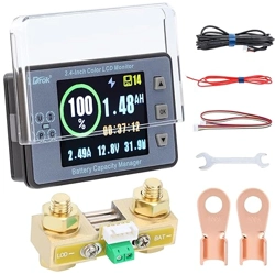
Furrion battery monitor measures voltage, current, and battery
capacity in real time. It can help user accurately understand the
status of battery pack, and includes a power-down memory
function.
This product works with 8V~30V battery pack, such as the most
common RV deep cycle; Wet cell, AGM and Lithium batteries.
● Model FBM08A10C should be used for battery current that is
less than 100A.
● Model FBM08A35C should be used for battery current that is
larger than 100A and less than 350A.
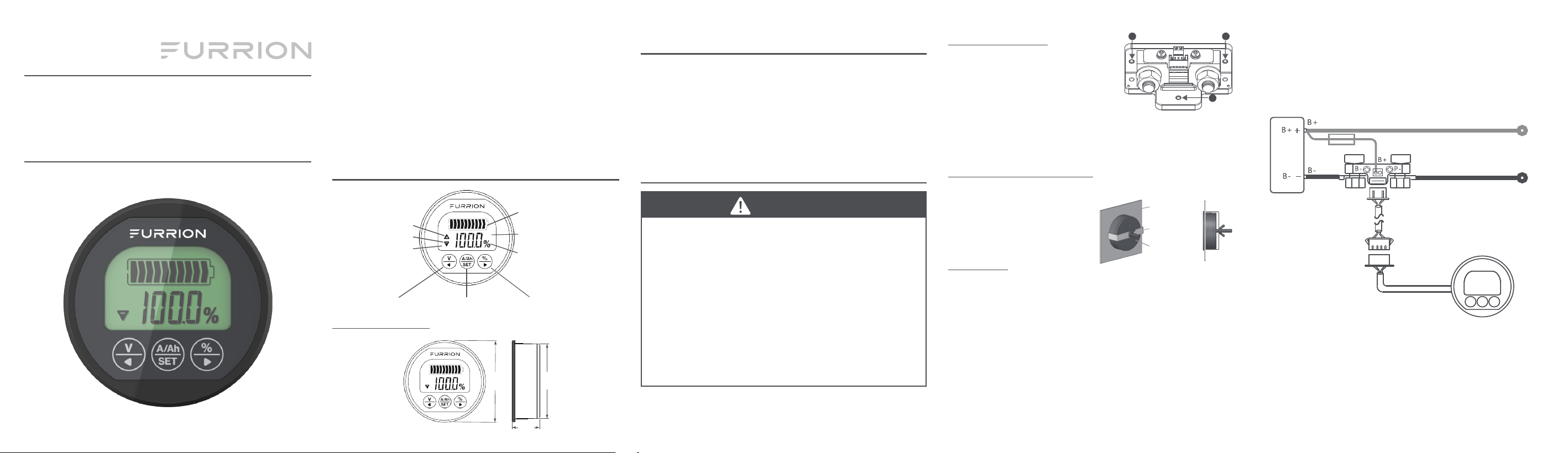
PRODUCT OVERVIEW
Battery Symbol
Symbol V: Present Voltage
Symbol A: Present Current
Symbol Ah: Present Capacity
Capacity Percentage
Charging Indication
Discharging Indication
Displayed Value
Percentage/Plus KeyCurrent/Capacity/Setting KeyVoltage/Reducing Key
Product Dimension
59 mm
20 mm
54 mm
Mounting the Shunt
Secure the shunt by using #4 or 3mm
screws with pan heads (not included),
to prevent accidental contact. There are
3 holes provided for mounting on the
shunt as shown.
NOTE: Mounting at least 2 holes is recommended. Do not place in
or cover with insulating material to allow adequate ventilation for
cooling.
Mounting the Power Monitor
Cut a 2⅛" (54.5mm) round hole on the equipment panel, tighten the
installation supporter with butterfly
Equipment Panel
Installation Support
Butterfly Nut
nut to clamp to the panel as shown.
NOTE: The “equipment panel” is
not included.
Connection
1. Connect the shunt in series with the negative circuit of the
battery pack as illustrated. Ensure the ends of the shunt
marked B- and P- are connected correctly as illustrated.
2. Connect a fused (5A max) AWG#18 to AWG#22 wire between
the shunt and a 12V+ supply as illustrated. Using a 2-2.5mm
slotted screwdriver is recommended to connect the shunt.
3. Connect the provided shielded wire between the shunt and
battery monitor as illustrated.
NOTE: The length of the shielded wire is 32.8 feet (10m).
Ensure the shunt and monitor are within reach. The shielded
wire can not be spliced to add length.
WHAT’S IN THE BOX
● Battery Monitor
● Shunt Resistor
● Shielded Cable Wire
● Mounting Clamp Bracket
● User Manual
● Warranty Manual
INSTALLATION
CAUTION
● Do not put the battery monitor in direct sunlight, or in the
environment below 14°F (-10°C) or above 140°F (60°C) for a
prolonged period, which will shorten the lifetime of the LCD
screen.
● The shunt is recommended to be put as close as possible
to the battery, but not be exposed directly to the elements,
e.g. rain.
● The shunt must be mechanically secured, as its metal
exposed parts are GND and if not secured could cause
unwanted shorts, fire, or even an explosion of the battery.
● Ensure wires connected to the battery are properly mounted
– nuts must be tightened securely, so that the wires don’t
move, get loose during vibrations.
NOTE: Most power consuming equipment utilizes the RV chassis
frame as a current return path to the battery. Therefore the battery
negative is bonded typically very close in proximity to the chassis.
The shunt must be added in-line between the battery and chassis
frame for accurate use of the meter. No other power consuming
component can be attached to B-, all loads must connect to P-.
P+ (Output Positive)
C- (Charging Negative)
P- (Output Negative)
Shunt Resistor
5A inline fuse
Battery
Pack
Shielded Wire - 32.8 feet (10m)
Connection Diagram
1
2
3

SET UP AND OPERATION
Battery Capacity Calibration and Setting
Each battery has a capacity rating, typically measured in Amp-hrs
(Ah). For accurate use, the meter needs to be calibrated and set for
the battery capacity.
NOTE:
● For multiple batteries tied in Parallel, add each battery capacity
together.
● For multiple batteries tied in Series, add the voltage together,
the capacity remains the same.
Discharge the battery bank by turning loads on in your RV and
disconnecting any charging equipment. DO NOT discharge battery
below 10.5 volts. Once discharged, begin the following:
1. Press
to display battery capacity %.
2. Press and Hold
for 3 seconds, this will calibrate the meter
to indicate the battery is at 0% capacity (empty).
3. Press
to display Ah battery capacity, then press for 3
seconds to enter setting mode.
4. Press
to increase Ah value to the max or a value reasonably
greater than the capacity of the battery bank. Press
to set
the value.
5. Charge the battery bank completely until the Ah or % capacity
stops increasing. Charging may take over 24hrs to stabilize.
6. Repeat step 3, 4, but instead set capacity to the Ah value
indicated by the meter from fully charging the battery bank.
(This is the true capacity of the battery bank.)
- Amp-hr (Ah) Battery Capacity: Press to display Ah.
The number displayed indicates the Amp-hr (Ah) power
capacity remaining in the battery bank.
- Battery Capacity “Fuel” Gauge: Press
to display the
% “Fuel” remaining in the battery. This is the easiest display
to understand how much power remains in the batteries until
empty.
Display Function
1. The display back-light will be a slow-cyclical pulsing
illumination if the battery is charging.
2. The display back-light will be a constant illumination if the
battery is dis-charging.
3. The display back-light will not illuminate if the battery is neither
charging or dis-charging.
NOTE:
● The display may flicker on/off when significant motor loads are
utilized, this is normal and does not change accuracy of the
meter.
● If significant interruptions occur due to nearby electric current
fluctuations, it may be necessary to relocate the meter.
Turning Back-light on/off
Press ( and ) together for 3 seconds to turn back-light on/off.
IM-FEN00032 V3.0
7. Press to display battery capacity %, press for 3
seconds to set the meter to 100%.
The meter is now calibrated and set for the capacity of the battery
bank.
NOTE: Battery capacity diminishes with age and charge cycles.
The meter does not self calibrate with change in Battery capacity.
Therefore, the above steps should be repeated occasionally to keep
accurate calibration.
The battery monitor will power on automatically, and for the first
time will display an arbitrary setting for battery capacity. After
calibration, the meter will always remember these settings until they
are manually changed.
Navigating the Meter Display
1. Checking Current: Press to display amperage (A) or
current. This will show the current flowing in and out of the
battery. If the arrow is the current is flowing into the battery
and is charging. Likewise, if the arrow is , the current is
flowing out of the battery and it is dis-charging.
2. Checking Voltage: Press
to display the real-time voltage of
your battery bank.
3. Checking Battery Capacity: It is important to monitor the
status of your battery capacity to ensure ample power will be
available. The capacity will increase or decrease depending if
the battery is charging or discharging. Battery capacity can be
displayed in two ways:
SPECIFICATIONS
Working Voltage 8~30V
Working Consumption 10.0~12.0mA
Stand-by Consumption 0.5~0.6mA
Sleep Consumption 50.0~60uA
Accuracy of Voltage Collecting ±1.0%
Accuracy of Current Collecting ±1.0%
Accuracy of Capacity Collecting ±1.0%
Back-light on Current
(>50A specification)
100mA
Setting Value of Capacity 0.1~999.0Ah
Temperature Range in Application
Environment
-10~60°C (14~140°F)
Weight of 100A Shunt 16.5oz (469g)
Weight of 350A Shunt 21.9oz (620g)
Shield Wire Length of 100A Shunt 32.8 feet (10m)
Shield Wire Length of 350A Shunt 32.8 feet (10m)
Appearance Size ø2⅜ x ¾" (ø59 x 20mm)
Hole Size ø2⅛" (ø54.5mm)
The
contents of this manual are proprietary and
copyright protected by Lippert. Lippert prohibits
the copying or dissemination of portions of this
manual unless prior written consent for an
authorized Lippert representation has been
provided. Any unauthorized use shall void any
applicable warranty. The information contained in
this manual is subject to change without notice
and at the sole discretion of Lippert. Revised
editions are available for free download fro
lippert.com.
Please recycle all obsolete materials.
For all concerns or questions, please contact
Lippert
Ph: 432-LIPPERT (432-547-7378) | Web:
lippert.com | E-mail: [email protected]
CCD-0005620 | REV DATE
: 10.20.22